self optimizing+networks benefits+of+son+in+lte july+2011
TRANSCRIPT
5/14/2018 Self Optimizing+Networks Benefits+of+SON+in+LTE July+2011 - slidepdf.com
http://slidepdf.com/reader/full/self-optimizingnetworks-benefitsofsoninlte-july2011
1
5/14/2018 Self Optimizing+Networks Benefits+of+SON+in+LTE July+2011 - slidepdf.com
http://slidepdf.com/reader/full/self-optimizingnetworks-benefitsofsoninlte-july2011
2
TABLE OF CONTENTS
1 INTRODUCTION ...................................................................................................................................... 5
1.1 Goals of this White Paper ............................................................................................................... 5
1.2 Technology and Market Drivers for SON ........................................................................................ 5
1.3 Reasons for Automation .................................................................................................................. 6
2 3GPP EVOLUTION AND SON ................................................................................................................ 7
2.1 LTE SON High-Level Scope and Timeline ...................................................................................... 7
2.2 SON Development in NGMN .......................................................................................................... 8
2.3 SON Architecture Alternatives ...................................................................................................... 11
3 KEY LTE RELEASE 8, RELEASE 9 AND RELEASE 10 FEATURES SON........................................ 13
3.1 Base Station Self-Configuration .................................................................................................... 13
3.1.1 Benefits .................................................................................................................................. 13
3.1.2 Description ............................................................................................................................. 13
3.1.3 Self-Configuration Actions ..................................................................................................... 14
3.1.4 Self-Configuration Status in 3GPP ........................................................................................ 15
3.2 Automatic Neighbor Relation (ANR) ............................................................................................. 15
3.2.1 Benefits .................................................................................................................................. 15
3.2.2 Description ............................................................................................................................. 16
3.2.3 Neighbor Relation Discovery ................................................................................................. 16
3.2.4 ANR Actions .......................................................................................................................... 16
3.2.5 Inter-RAT ANR ...................................................................................................................... 17
3.3 Tracking Area Planning ................................................................................................................. 18
3.3.1 Benefits .................................................................................................................................. 19
3.4 PCI Planning ................................................................................................................................. 19
3.4.1 Benefits .................................................................................................................................. 20
3.5 Load Balancing ............................................................................................................................. 20
3.5.1 Benefits .................................................................................................................................. 20
3.5.2 Description ............................................................................................................................. 21

5/14/2018 Self Optimizing+Networks Benefits+of+SON+in+LTE July+2011 - slidepdf.com
http://slidepdf.com/reader/full/self-optimizingnetworks-benefitsofsoninlte-july2011
3
3.5.3 Determining A Load Imbalance Condition ............................................................................. 21
3.5.4 Idle Mode Load Balancing ..................................................................................................... 22
3.5.5 Active Mode Load Balancing ................................................................................................. 22
3.5.6 Adapting Handover Configuration ......................................................................................... 23
3.6 Mobility Robustness / Handover Optimization .............................................................................. 24
3.6.1 Benefits .................................................................................................................................. 24
3.6.2 Description ............................................................................................................................. 24
3.6.3 Intra-RAT Late HO Triggering ............................................................................................... 25
3.6.4 Intra-RAT Early HO Triggering .............................................................................................. 26
3.6.5 Intra-RAT HO to an Incorrect Cell ......................................................................................... 27
3.6.6 Inter RAT Too Late HO ......................................................................................................... 28
3.6.7 Inter RAT Unnecessary (too early) HO ................................................................................. 29
3.6.8 Algorithm for SON Handover Parameter Optimization.......................................................... 29
3.6.9 Examples of SON Algorithm Interactions .............................................................................. 30
3.7 RACH (Random access channel) Optimization ............................................................................ 31
3.7.1 Benefits .................................................................................................................................. 31
3.7.2 Description ............................................................................................................................. 31
3.8 Inter Cell Interference Coordination .............................................................................................. 32
3.8.1 Benefits .................................................................................................................................. 33
3.8.2 Description of ICIC operation ................................................................................................ 33
3.8.3 Frequency Planning .............................................................................................................. 35
3.8.4 Self-Tuning X2 Independent Algorithms ............................................................................... 35
3.8.5 Performance of ICIC Techniques Relative to Self-Tuning X2 Independent Algorithms ........ 36
3.8.6 Optimization of Coverage/Intererence with H-eNB ............................................................... 36
3.8.7 Release-10 ICIC Enhancements ........................................................................................... 38
3.9 Energy Savings ............................................................................................................................. 38
3.9.1 Benefits .................................................................................................................................. 39
3.9.2 Description ............................................................................................................................. 39

5/14/2018 Self Optimizing+Networks Benefits+of+SON+in+LTE July+2011 - slidepdf.com
http://slidepdf.com/reader/full/self-optimizingnetworks-benefitsofsoninlte-july2011
4
3.9.3 Deployment Scenarios with LTE in Clusters, Overlaying an Underlying 2G/3G Network .... 40
3.9.4 Scenarios for Further Study .................................................................................................. 41
3.10 Celloutage Detection And Compensation ..................................................................................... 42
3.10.1 Benefits .................................................................................................................................. 42
3.10.2 Cell Outage Detection ........................................................................................................... 43
3.10.3 Cell Outage Compensation ................................................................................................... 43
3.11 Coverage And Capacity Optimization ........................................................................................... 47
3.11.1 Modification of Antenna Tilts ................................................................................................. 47
3.11.2 Minimization of Drive Tests ................................................................................................... 53
3.12 Applications of SON to Address Deployment and Operation of DAS and Small Cells.................56
3.12.1 SON Interactions with Distributed Antenna Systems ............................................................ 56
3.12.2 SON with Picos/Femtos/Relays ............................................................................................ 56
3.12.3 Using SON to Facilitate the Deployment of Repeaters/Relays ............................................. 57
4 4G AMERICAS OPERATOR USECASES ............................................................................................ 59
4.1 4G Operator Usecase: ANR/PCI................................................................................................... 59
4.1.1 ANR/PCI Phase 1 .................................................................................................................. 59
4.1.2 ANR/PCI Phase 2 .................................................................................................................. 59
4.1.3 ANR/PCI Phase 3 .................................................................................................................. 60
4.2 4G Operator Usecase: Cell Outage .............................................................................................. 60
4.2.1 Cell Outage Detection ................................................................................................................ 60
4.2.2 Cell Outage Compensation Through Antenna Tilt Modificaton – PHASE 1 .............................. 60
4.2.3 Cell Outage Compensation Through Antenna Tilt Modification– PHASE 2 .............................. 60
5 RESULTS FROM LIVE OR TRIAL NETWORKS ................................................................................. 62
6 SON CAPABILITIES IN HSPA+ TECHNOLOGY ................................................................................. 65
7 SUMMARY AND CONCLUSION ........................................................................................................... 66
LIST OF ACRONYMS ................................................................................................................................ 67
ACKNOWLEDGEMENTS ........................................................................................................................... 68
REFERENCES ............................................................................................................................................ 69

5/14/2018 Self Optimizing+Networks Benefits+of+SON+in+LTE July+2011 - slidepdf.com
http://slidepdf.com/reader/full/self-optimizingnetworks-benefitsofsoninlte-july2011
5
1 INTRODUCTION
1.1 GOALS OF THIS WHITE PAPER
In today's mobile wireless networks, many network elements and associated parameters are manually
configured. Planning, commissioning, configuration, integration and management of these parameters areessential for efficient and reliable network operation; however, the associated operations costs are
significant. Specialized expertise must be maintained to tune these network parameters, and the existing
manual process is time-consuming and potentially error-prone. In addition, this manual tuning process
inherently results in comparatively long delays in updating values in response to the often rapidly-
changing network topologies and operating conditions, resulting in sub-optimal network performance.
The recent deployment of LTE to address the growing data capacity crunch, has highlighted the need and
value of self-organizing capabilities within the network that permit reductions in operational expenses
(OPEX), during deployment as well as during continuing operations. Self-optimizing capabilities in the
network will lead to higher end user Quality of Experience (QoE) and reduced churn, thus allowing for
overall improved network performance. SON improves network performance, but in no way replaces the
wireless industry’s important need for more spectrum to meeting the rising mobile data demands from
subscribers.
3GPP initiated the work towards standardizing self-optimizing and self-organizing capabilities for LTE, in
Release 8 and Release 9. The standards provide network intelligence, automation and network
management features in order to automate the configuration and optimization of wireless networks to
adapt to varying radio channel conditions, thereby lowering costs, improving network performance and
flexibility. This effort has continued in Release 10 with additional enhancements in each of the above
areas and new areas allowing for inter-radio access technology operation, enhanced inter-cell
interference coordination, coverage and capacity optimization, energy efficiency and minimization of
operational expenses through minimization of drive tests. This paper discusses the Release 8, Release 9
and Release 10 Self-Organizing Network (SON) techniques and explains how these capabilities willpositively impact network operations in the evolved LTE network. Application of SON techniques by a 4G
Americas member company operator in LTE networks and live results from the application of SON to
HSPA+ networks are described, thus demonstrating the potential benefits of SON. Application of SON
techniques to address deployment and operational challenges with Distributed Antenna Systems (DAS),
and picos, femtos and relays are described to address the impact of SON on a variety of radio systems.
This paper is an update of the paper published in 2009 on “Benefits of SON in LTE”17
that addressed the
rationale for SON and the description of SON features in 3GPP Releases 8 and 9.
1.2 TECHNOLOGY AND MARKET DRIVERS FOR SON
Reflecting upon recent wireless industry events, 4G Americas member companies observe several
important trends that are driving additional network complexity and operations effort.
New and emerging classes of mobile devices (smartphones, PC data cards, USB modems, consumer
devices with embedded wireless, machine-to-machine, etc.) are fostering explosive growth of wireless
data usage by public and enterprise users. As a result, wireless service providers have to simultaneously
support a growing number of higher-bandwidth data applications and services on their networks. The list
of user applications and services is quite broad in scope, and includes Internet browsing, Web 2.0, audio,

5/14/2018 Self Optimizing+Networks Benefits+of+SON+in+LTE July+2011 - slidepdf.com
http://slidepdf.com/reader/full/self-optimizingnetworks-benefitsofsoninlte-july2011
6
video, video on demand, gaming, location-based services, social networking, peer-to-peer, advertising,
etc.
On the network side, wireless service provider networks are becoming more complex and heterogeneous.
Projections point to rapidly growing numbers of femto and picocells (in order to drive greater coverage
and/or offload capacity from macrocells), plus increasing prevalence of multi-technology networks (2G,
3G, 4G, plus WiFi). These trends pose potentially significant operational and network complexityregarding macro/femto and inter-technology handover, as well as management of macro/femto and
macro/pico interference. Taken together, these trends place ever-increasing demands upon service
providers’ networks and their operational staff. Ensuring quality user experience requires more complex
Quality of Service (QoS) and policy implementations while they simultaneously must increase network
throughput in response to the rapid growth in wireless data.
Moreover, wireless data revenue measured on a per-megabit (Mb) basis is decreasing. Fortunately,
spectral efficiency gains are provided by new wireless technologies, and do provide some measure of
relief; however, the data throughput per user is growing (and revenue per Mb is dropping) so rapidly that
spectral efficiency gains alone appear unable to keep up. Consequently, service providers – and
infrastructure vendors – are increasing their focus on operational cost reductions. Reflecting upon these
dramatic trends, it has become clear that traditional network management needs significant improvement
for managing this growing data volume and network complexity in a cost-effective manner.
1.3 REASONS FOR AUTOMATION
At a high level, there are two underlying operational issues facing service providers. Some processes are
repetitive, while others are too fast or difficult to be performed manually. The rationale for SON
automation can be grouped into two broad categories:
1. Previously manual processes that are automated primarily to reduce the manual intervention in
network operations in order to obtain operational and/or deployment savings. Automating
repetitive processes clearly saves time and reduces effort. Auto-configuration and self-configuration fall into this category.
2. Processes that require automation because they are too fast, too granular (per-user, per-
application, per-flow, as a function of time or loading), and/or too complex for manual intervention.
Automatically collected measurements from multiple sources (e.g., from user devices, individual
network elements, and on an end-to-end basis from advanced monitoring tools) will provide
accurate real time and near real time data upon which these algorithms can operate thus
providing performance, quality, and/or operational benefits.
Consequently, substantial opportunities exist for cross-layer, end-to-end, and per-user/per-application/
per-flow optimizations for extracting additional performance benefits and management flexibility. These
categories need not be distinct, (e.g., a previously manual process that is growing too complex due to theabove trends) may by necessity require automation in order to manage it.
Automation is not a new concept for wireless networks – clearly networks already critically depend on
extensive use of automated processes. For instance, numerous examples abound just in the area of radio
resource management (scheduling, power and/or rate control, etc.) that demonstrate that these
automated features perform well. Thus, the appearance of SON algorithms represents a continuation of
the natural evolution of wireless networks, where automated processes are simply extending their scope
deeper into the network.

5/14/2018 Self Optimizing+Networks Benefits+of+SON+in+LTE July+2011 - slidepdf.com
http://slidepdf.com/reader/full/self-optimizingnetworks-benefitsofsoninlte-july2011
7
2 3G PP E V O L U T I O N AN D S ON
2.1 LTE SON HIGH‐LEVEL SCOPE AND TIMELINE
Self-Organizing Networks capability is a key component of the LTE network. SON concepts have been
included in the LTE (E-UTRAN) standards starting from the first release of the technology (3GPP Release8), and expanding in scope with subsequent releases (3GPP Release 9 and 3GPP Release 10). Figure 1
provides the standardization timelines for the different 3GPP LTE releases, throughout which SON
capabilities have been developed and enhanced.
Figure 1 - 3GPP LTE Specifications Timelines. Release 10 specifications were frozen in March
2011 and will be complete in Mid 2011.
A key goal of 3GPP standardization has been the ability to support SON features in multi-vendor network
environments. Therefore, a significant part of the SON standardization has been devoted to defining the
appropriate interfaces to allow exchange of common information which can then be used by each SON
algorithm. The SON specifications have been built over the existing 3GPP network managementarchitecture, reusing much functionality that existed prior to Release 8. These management interfaces are
being defined in a generic manner to leave room for innovation on different vendor implementations. In
addition to specifying the interfaces, 3GPP has defined a set of LTE SON use cases and associated SON
functions.1
The standardized SON features effectively track the expected LTE network evolution stages
as a function of time, following expected commercial network maturity. As such, the focus of the Release
8 SON functionality was put on procedures associated with initial equipment installation and integration to
support the commercial deployment of the first LTE networks, also known as “eNB self-configuration”.
These procedures included:
Automatic Inventory
Automatic Software Download
2
Automatic Neighbor Relation3
Automatic Physical Cell ID (PCI) assignment4
Following this reasoning, the next release of SON (Release 9) provided SON functionality covering
operational aspects of already commercial networks, in particular key aspects related to network
optimization procedures. The Release 9 standardization scope included these additional use cases:

5/14/2018 Self Optimizing+Networks Benefits+of+SON+in+LTE July+2011 - slidepdf.com
http://slidepdf.com/reader/full/self-optimizingnetworks-benefitsofsoninlte-july2011
8
Mobility Robustness/Hand Over optimization
RACH optimization
Load Balancing optimization
Inter-Cell Interference Coordination
The latest release of SON, being standardized in Release 10, provides a richer suite of SON functions for
macro and metro networks overlaid on and interoperating with existing mobile networks. It includes
enhancements to existing use cases and definition of new use cases as follows:
Coverage & Capacity optimization
Enhanced Inter-Cell Interference Coordination
Cell Outage Detection and Compensation
Self-healing functions
Minimization of Drive Testing
Energy Savings
The SON standards are a work in progress, and SON-related functionality will continue to expand through
the subsequent releases of the LTE standard, Release 11 and beyond, to cover all key aspects related to
network management, troubleshooting and optimization in multi-layer, multi-RAT heterogeneous
networks.
2.2 SON DEVELOPMENT IN NGMN
In 2006, a group of operators created the Next Generation Mobile Networks (NGMN) Alliance with the
objective to provide business requirements to the new technologies being developed. In practice, NGMN
recommendations provide guidance to the technical standards being developed for LTE, indicating the
key use cases that are most important for carriers’ day to day operations. These use cases have been
identified by the operators as the typical tasks that will be performed by their engineers in their day-to-day
operations; therefore, a better system of integration and automation would result in a more efficient
utilization of the operator resources, both material (spectrum, equipment, etc.) and human (engineering
time).
NGMN’s first whitepaper included high-level requirements for Self-Optimization network strategies5, and
sometime later a concrete set of use cases was defined, covering multiple aspects of the network
operations including planning, deployment, optimization and maintenance6. On the next page is a
definition of the top 10 use cases indicated by NGMN, many of which have already been introduced in the
3GPP standards.

5/14/2018 Self Optimizing+Networks Benefits+of+SON+in+LTE July+2011 - slidepdf.com
http://slidepdf.com/reader/full/self-optimizingnetworks-benefitsofsoninlte-july2011
9
1 Plug & Play Installation
2 Automatic Neighbor Relation configuration
3 OSS Integration
4 Handover Optimization
5 Minimization of Drive Tests
6 Cell Outage Compensation
7 Load Balancing
8 Energy Savings
9 Interaction home/macro BTS
10 QoS Optimization
NGMN uses cases are defined at a higher level than 3GPP specifications, and are introduced way ahead
of them, providing an initial guidance to the standards development and in some cases complementing
existing standard functionality. A specific example is the interaction between home/macro BTS, for which
NGMN has provided extensive recommendations to avoid excessive interference in the network (see
section 3.8.6 for more details) and which in part has been standardized in 3GPP Release 10.
Another NGMN use case not yet developed by 3GPP is the optimization of QoS related parameters. QoS
functionality is considered very important for wireless operators, especially with the deployment of very
high-speed networks where data consumption is steadily increasing and will be approaching that of fixed
broadband. Typically, the optimization of QoS related parameters governing the different network entities
(scheduler, admission control, mobility, etc.) is very complex and requires expert resources. NGMN
reckons that in the future, the networks should be able to adapt their quality automatically in response to
external factors such as high load in specific areas, or based on special traffic patterns. At this point, the
specific mechanisms to be used are not defined. However, NGMN has proposed a set of information
elements that should be made available to be able to easily define such mechanisms. Below is a set of
performance monitoring (PM) counters recommended for standardization:
Number of successful sessions per QoS Class Identifier (QCI)
Number of dropped sessions per QCI
Cell specific customer satisfaction rate
Min/Avg/Max throughput per QCI
Min/Avg/Max round trip delay per QCI
Packet loss per QCI

5/14/2018 Self Optimizing+Networks Benefits+of+SON+in+LTE July+2011 - slidepdf.com
http://slidepdf.com/reader/full/self-optimizingnetworks-benefitsofsoninlte-july2011
10
Mean number of Radio Resource Control (RRC) connected users
Mean number of RRC connected UEs with data to send per QCI
Percentage of UEs per cell that is not achieving their required GBR and not achieving the
required service data unit (SDU) error ratio per QCI
Percentage of UEs for which transfer delay per IP packet was above a particular threshold
Percentage of UEs for which average throughput measured at RLC layer for each non-real time
(nRT) QCI was below a particular threshold
Percentage of UEs per QCI for which the SDU error ratio is above a certain level
Number of RRC connected UEs with measurement gaps configured.
In addition to the definition of use case functionality, the SON group in NGMN has been very active in
defining Operations Support System (OSS) aspects of SON. These include support for more open OAM
interfaces, and procedures to support the integration of non-3GPP elements such as operator databases
and tools.
The objective of the OAM effort is to ensure a true multi-vendor ecosystem, where entities from different
manufacturers could operate together in an automatic fashion.16
For this purpose, a more open definition
of the Northbound Interface (Itf-N) in 3GPP has been requested to reduce the integration efforts between
the Network Management System (NMS) and the Element Management System (EMS), together with
real-time reporting requirements to allow a third party vendor to take timely action in the network. In
addition to generic requirements, the OPE recommendations define use-case specific OAM actions, as is
the case of the Handover Optimization and Cell Outage Compensation. Other aspects covered by this
project are the standardization of performance management information (counters and key performance
indicators or KPIs) and their exchange formats.
The integration of OSS tools is also a very active area in NGMN. In every network deployment, there is a
multitude of non-3GPP related elements that the operator needs to integrate with their existing network
elements, such as RF planning databases, work flow databases and optimization tools (cell planning
tools, third party SON tools, etc.). In order to integrate such entities, NGMN provides a set of generic
guidelines including the following:
Capability to run SON functionality in open (operator controlled) and closed (fully automatic) loop
modes
Deactivation of SON features in the Network Elements to pass control to the operator or external
entities
Support of centralized, distributed and hybrid architectures
Real time synchronization with NMS
Supply of relevant statistics and historical view to NMS
Customization of SON policies.

5/14/2018 Self Optimizing+Networks Benefits+of+SON+in+LTE July+2011 - slidepdf.com
http://slidepdf.com/reader/full/self-optimizingnetworks-benefitsofsoninlte-july2011
11
In addition to generic guidelines, NGMN provides specific use-cases requirements for each of the use
cases defined in 3GPP and NGMN. For example, in the case of the Automatic Neighbor Relation (ANR)
usecase, NGMN requirements for full OSS integration are listed below:
Support of CM Northbound Interface 3GPP BulkCM IRP (Bulk Configuration Management
Integration Reference Point). ANR based changes in the eNB shall be "online" synchronized with
EMS.
Support of real time relationship configuration to ensure that HO is possible a few seconds after
neighbor detection.
OSS should be able to indicate which entity (such as the eNB or some other entity) takes control
of the configuration for a given feature, say automatic neighbor relations (ANR).
OSS should provide monitoring support of the main ANR steps: neighbor cell detection, X2 set-
up, neighbor cell configuration adaptation and ANR optimization
2.3 SON ARCHITECTURE ALTERNATIVES
The specification covering the SON overview15
identifies three different architectures for SON
functionality: (a) Distributed, (b) Centralized and (c) Hybrid as shown in Figure 2.
Figure 2 – Different SON architecture approaches:Centralized (left), Distributed (center) and Hybrid (right)
In a centralized architecture, SON algorithms for one or more usecases reside on the Element
Management System or a separate SON server that manages the eNBs. The output of the SON
algorithms namely, the values of specific parameters, are then passed to the eNBs either on a periodic
basis or when needed. A centralized approach allows for more manageable implementation of the SON
algorithms. It allows for usecase interactions between SON algorithms to be considered before modifying
SON parameters. However, active updates to the usecase parameters are delayed since KPIs and UE
measurement information must be forwarded to a centralized location for processing. Filtered and
condensed information are passed from the eNB to the centralized SON server to preserve the scalability
of the solution in terms of the volume of information transported. Less information is available at the SON
5/14/2018 Self Optimizing+Networks Benefits+of+SON+in+LTE July+2011 - slidepdf.com
http://slidepdf.com/reader/full/self-optimizingnetworks-benefitsofsoninlte-july2011
12
server compared to that which would be available at the eNB. Higher latency due to the time taken to
collect UE information restricts the applicability of a purely centralized SON architecture to those
algorithms that require slower response time. Furthermore, since the centralized SON server presents a
single point of failure, an outage in the centralized server or backhaul could result in stale and outdated
parameters being used at the eNB due to likely less frequent updates of SON parameters at the eNB
compared to that is possible in a distributed solution.
There are three key time intervals associated with Centralized SON.
The Collection Interval is the period during which statistics are collected and uploaded. This is
also the smallest available granularity for data analysis. This interval is most likely determined by
the vendors OAM statistics throughput limitations. Most Network Management solutions would
typically support a five minutes interval.
The Analysis Interval is the time period considered in the decision process for parameter
adjustment. It is beneficial to consider more than a single collection interval in the analysis. While
the latest collection interval should have the greatest impact on the analysis, the output should be
damped to take into account results from previous intervals.
The Change Interval is the period between changes applied to the network by SON. System
performance constraints may limit the number of cells for which changes are applied at any given
time. This could result in Change Intervals that do not align directly with the Collection Intervals.
These limiting factors don’t always apply, but centralized solutions either need to have vastly over
provisioned processing and networking capability, or intelligent change management.
In a distributed approach, SON algorithms reside within the eNB’s, thus allowing autonomous decision
making at the eNBs based on UE measurements received on the eNBs and additional information from
other eNBs being received via the X2 interface. A distributed architecture allows for ease of deployment
in multi-vendor networks and optimization on faster time scales. Optimization could be done for different
times of the day. However, due to the inability to ensure standard and identical implementation of
algorithms in a multi-vendor network, careful monitoring of KPIs is needed to minimize potential network
instabilities and ensure overall optimal operation.
In practical deployments, these architecture alternatives are not mutually exclusive and could coexist for
different purposes, as is realized in a hybrid SON approach. In a hybrid approach, part of a given SON
optimization algorithm are executed in the NMS while another part of the same SON algorithm could be
executed in the eNB. For example, the values of the initial parameters could be done in a centralized
server and updates and refinement to those parameters in response to the actual UE measurements
could be done on the eNBs. Each implementation has its own advantages and disadvantages. The
choice of centralized, distributed or hybrid architecture needs to be decided on a use-case by use case
basis depending on the information availability, processing and speed of response requirements of that
use case. In the case of a hybrid or centralized solution, a practical deployment would require specific
partnership between the infrastructure vendor, the operator and possibly a third party tool company.
Operators can choose the most suitable approach depending upon the current infrastructure deployment.

5/14/2018 Self Optimizing+Networks Benefits+of+SON+in+LTE July+2011 - slidepdf.com
http://slidepdf.com/reader/full/self-optimizingnetworks-benefitsofsoninlte-july2011
13
3 KEY LTE RELEASE 8, RELEASE 9 AND RELEASE 10 FEATURES SON
3.1 BASE STATION SELF‐CONFIGURATION
The deployment of a new network technology is a major investment for any service provider. In addition
to the spectrum and equipment costs, the operator faces multiple challenges related to the networkplanning, commissioning and integration that often result in higher costs than the infrastructure equipment
itself. Today, there are a number of computer-aid design tools that an operator uses to simplify these
tasks, such as propagation tools, automatic cell planning (ACP) or automatic frequency planning (AFP)
tools. However, much of the process related to network element integration and configuration is still
performed manually. When a new base station (eNB) is installed, it requires that most aspects of its
configuration are provided by the engineer(s) on site, including the setup of the transport links, adding the
node to the corresponding concentration node (BTS or RNC), and establishing the connectivity with the
core network. This is in addition to the configuration of all the radio-related parameters such as the cable
and feeder loss adjustments, antenna type and orientation, transmit power, neighbor relations, etc. All
these processes are cumbersome, time-consuming, error-prone, and, in general, will require the
presence of more than one expert engineer, all the above resulting in an inefficient and costly process.
The objective of the Self-Configuration SON functionality is to reduce the amount of human intervention in
the overall installation process by providing “plug and play” functionality in the eNBs. As will be seen in
later sections, the scope of self-configuration functionality is expected to expand and evolve with
upcoming versions of the LTE standard.
3.1.1 BENEFITS
Self-Configuration of eNBs will reduce the amount of manual processes involved in the planning,
integration and configuration of new eNBs. This will result in a faster network deployment and reduced
costs for the operator in addition to a more integral inventory management system that is less prone to
human error.
3.1.2 DESCRIPTION
Self-Configuration is a broad concept which involves several distinct functions that are covered through
specific SON features, such as Automatic Software Management, Self Test and Automatic Neighbor
Relation configuration.
The Self-Configuration algorithm should take care of all soft-configuration aspects of the eNB once it is
commissioned and powered up for the first time. It should detect the transport link and establish a
connection with the core network elements, download and upgrade the corresponding software version,
setup the initial configuration parameters including neighbor relations, perform a self-test and finally set
itself to operational mode.
In order to achieve these goals, the eNB should be able to communicate with several different entities, as
depicted in the figure below.

5/14/2018 Self Optimizing+Networks Benefits+of+SON+in+LTE July+2011 - slidepdf.com
http://slidepdf.com/reader/full/self-optimizingnetworks-benefitsofsoninlte-july2011
14
Figure 3 - Self-Configuration of eNB in LTE
To be able to successfully achieve all functions the following prerequisites should at least be met prior to
the installation of the new node:
1. A network planning exercise for the cell should have been completed resulting in a set of RF
parameters, including location, cell identities, antenna configuration (height, azimuth & type),
transmit power, maximum configured capacity and initial neighbor configuration. This information
should be made available in the configuration server.
2. The transport parameters for the eNB should be planned in advance, including bandwidth, VLAN
partition, IP addresses, etc. The IP address range and Serving Gateway address correspondingto the node should be made available in the configuration server.
3. An updated software package download should be made available from the OSS.
The specific set of actions involved in the process will be covered in the next section.
3 . 1 . 3 S E L F‐CO NFI G UR ATI O N A C T I O N S
The Self-Configuration actions will take place after the eNB is physically installed, plugged to the power
line and to the transport link. When it is powered on, the eNB will boot and perform a Self Test, followed
by a set of self discovery functions, which include the detection of the transport type, Tower-Mounted
Amplifier (TMA), antenna, antenna cable length and auto-adjustment of the receiver-path.
After the self-detection function, the eNB will configure the physical transport link autonomously and
establish a connection with the DHCP/DNS servers, which will then provide the IP addresses for the new
node and those of the relevant network nodes, including Serving Gateway, MME and configuration
server. After this, the eNB will be able to establish secure tunnels for OAM, S1 and X2 links and will be
ready to communicate with the configuration server in order to acquire new configuration parameters.
DHCP/DNS Server
Configuration,
performance &
New eNB
Existing eNB
SGW
MME
OSS
5/14/2018 Self Optimizing+Networks Benefits+of+SON+in+LTE July+2011 - slidepdf.com
http://slidepdf.com/reader/full/self-optimizingnetworks-benefitsofsoninlte-july2011
15
One of the OAM tunnels created will communicate the eNB with a dedicated management entity, which
contains the software package that is required to be installed. The eNB will then download and install the
corresponding version of the eNB software, together with the eNB configuration file. Such configuration
file contains the pre-configured radio parameters that were previously planned.
Note that at the time of the installation most of the radio parameters will have the default vendor values. A
finer parameter optimization will take place after the eNB is in operational state (self-optimizationfunctions). The configuration of neighbor relations can optionally be performed through an automated
SON functionality that is covered in a separate section of this paper, otherwise the initial setup will be
done according to the output of the network planning exercise.
After the node is properly configured, it will perform a self-test that will include hardware and software
functions, and will deliver a status report to the network management node. Also, the unit will be
automatically updated in the inventory database that will incorporate the unique hardware identifier, as
well as the current configuration and status of the node.
3.1.4 SELF‐CONFIGURATION STATUS IN 3GPP
Current LTE standards incorporate functionality related to the self-configuration of eNB, including
Automatic Software Management,7
Self Test,8
Automatic Neighbor Relation,9
and Automatic Inventory
Management.10
It is expected that the first versions of the eNB self-configuration functionality in the eNB
will have vendor-dependent aspects, as 3GPP has not fully specified a standardized self-configuration
functionality. Examples of open areas in the standards include:
A defined interface between operator planning tools, equipment inventory and network
management entities
Configuration of transport parameters
Specific message formats for implementing the overall process
3.2 AUTOMATIC NEIGHBOR RELATION (ANR)
One of the more labor-intense areas in existing radio technologies is the handling of neighbor relations for
handover. It is a continuous activity that may be more intense during network expansion but is still a time-
consuming task in mature networks. The task is multiplied with several layers of cells when having
several networks to manage. With LTE, one more layer of cells is added; thus optimization of neighbor
relations may be more complex. Even with the best methods at hand, due to the sheer size of large radio
networks – with several hundred thousands of neighbor relations for a single operator – it is a huge
undertaking to maintain the neighbor relations manually. Neighbor cell relations are therefore an obvious
area for automation, and Automatic Neighbor Relation (ANR) is one of the most important features for
SON. To explore its full potential, ANR must be supported between network equipment from differentvendors. ANR is, therefore, one of the first SON functions to be standardized in 3GPP.
11
3.2.1 BENEFITS
ANR will remove, or at least minimize, the manual handling of neighbor relations when establishing new
eNBs and when optimizing neighbor lists. This will increase the number of successful handovers and lead
to less dropped connections due to missing neighbor relations.

5/14/2018 Self Optimizing+Networks Benefits+of+SON+in+LTE July+2011 - slidepdf.com
http://slidepdf.com/reader/full/self-optimizingnetworks-benefitsofsoninlte-july2011
16
3 . 2 . 2 D E S C R I P T I O N
Figure 4 - Automatic Neighbor Relation (ANR) in LTE
The ANR in LTE allows automatic discovery and setup of neighbor relations when a user (UE) moves
from a serving eNB to another (target) eNB. ANR also automatically sets up of the LTE unique X2
interface between eNBs, primarily used for handover.
There are two LTE distinctive functions that make ANR possible:
1. The UEs in LTE do not require a neighboring list and the reporting of unknown cells is fast
enough to be used during handover preparation. It enables ANR to receive handover
measurements on unknown cells that are not yet known by the serving eNB.
2. The possibility for the eNB to request the UE to make a full identification of a cell. It allows eNB to
determine an unambiguous identity of a neighboring cell.
3 . 2 . 3 N E I G H B O R R E L A T I O N D I S C O V E R Y
The UE is ordered to report measurements to the serving eNB directly after the RRC connection is set up
(i.e. is attached to the cell) and continues to do so while staying in RRC connected mode. The UE reports
all detected PCIs (Physical Cell Identities) – the short identity of the LTE cell – that fulfill the measurement
criteria set by the eNB at RRC connection. The UE may also measure on legacy radio technologies if it
supports multi-mode operation.
If there is an unknown cell included in the measurement report then ANR may begin actions to make thecell known and potentially enable handover to the cell.
3 . 2 . 4 A N R A C T I O N S
If a PCI is reported by a UE that does not correspond to any of the serving eNBs’ defined neighbor cells
(i.e. it is not a neighbor cell), the ANR function in the serving eNB may request the UE to retrieve the
Global Cell Identity (GCI) of the cell with the unknown PCI in order to identify the cell. This cell is from
now called target cell (see figure 4 above). The UE reads the GCI, which is broadcast by the target cell
Target eNB
Serving eNB
S1
X2
SAE
UE

5/14/2018 Self Optimizing+Networks Benefits+of+SON+in+LTE July+2011 - slidepdf.com
http://slidepdf.com/reader/full/self-optimizingnetworks-benefitsofsoninlte-july2011
17
and reports it to the serving eNB. When the serving eNB receives the GCI, it can – with help from MME,
one part of SAE – retrieve the target eNB’s IP address, which makes it possible for the serving eNB to
contact the target eNB.
The serving and target eNBs are now in contact with each other and X2 can be setup. The serving eNB
requests X2 setup to the target eNB and includes all necessary cell data to create a neighbor relation (i.e.
PCI, GCI, TAC, PLMN-id and frequency) from the target cell to the serving cell. The target cell adds theserving cell to its neighbor list and the target eNB sends the corresponding data for the target cell (PCI,
GCI, TAC, PLMN-id and frequency) to the serving cell which in turn adds the target cell to its neighbor list.
With the X2 interface in place, it is possible to use X2 for all future handovers between the cells. For
handover from LTE to legacy systems (i.e. GSM and WCDMA), ANR works in the same way with the
exception that it only needs to setup a neighbor relation to the target cell and not the X2 since the
handover to non-LTE systems is always performed over SAE.
ANR can automatically remove unused neighbor relations based on the relation usage, handover
performance or a combination thereof.
When adding and removing neighbors, ANR is under control of policies set by the operator. The blacklisting allows the operator to decide neighbor relations that ANR may never add as neighbors. The white
listing allows the operator to decide permanent neighbor relations that ANR may never remove. These
policies are controlled from an Element Management System (EMS) such as OSS.
3.2.5 INTER‐RAT ANR
The inter-RAT ANR is applicable when different mobile network standards such as GSM, UMTS/HSPA,
CDMA/EV-DO and LTE are deployed to cover the same geographical area.
In this section, the ANR Inter-RAT function is explained for the case when LTE is overlaid on one of the
other networks, hereafter referred to as underlying networks. LTE is normally deployed on the same sites
as the underlying network’s radio base stations. It will therefore partially or fully cover the same area asthe underlying network. Inter-RAT handover between LTE and an underlying network could be used for
circuit switch (CS) fallback to the existing networks for voice calls and SMS, and load balancing of UEs
when traffic on a network exceeds a threshold. This means that the UEs could handover between LTE
and the underlying network even when the LTE cell coverage is good. Based on the above assumptions,
the ANR function in LTE must be able to find the underlying network’s cells with the same coverage as
the LTE cells. To find these neighbors, an additional ANR method in LTE needs to be introduced whereby
the UEs are ordered to report best serving cell periodically.
The ANR function in LTE orders the ANR capable multi-standard UEs, connected to LTE, to report best
serving cell measurements from the underlying network periodically. There are different possible solutions
for ordering the multi-standard UEs depending on which technology is used in the underlying network.
The new SON unique report configuration, “ReportStrongestCellsForSon ” could be used for UMTS/HSPA
and CDMA/EV-DO. The existing “ReportStrongestCells ” could be used for GSM. They are specified in
3GPP 36.331 (Release-8) and are used for specifying criteria for triggering of inter-RAT measurement
reporting events B1 and B2. Event B1 refers to the event when inter-RAT neighbor has a higher value of
RSRP/RSRQ than a threshold. Event B2 refers to the event when the serving cell has a lower of
RSRP/RSRQ than a threshold, and inter RAT neighbor has a higher value than a threshold.

5/14/2018 Self Optimizing+Networks Benefits+of+SON+in+LTE July+2011 - slidepdf.com
http://slidepdf.com/reader/full/self-optimizingnetworks-benefitsofsoninlte-july2011
18
To minimize the load on the UEs, the ANR function in LTE should be able to adapt the number of UE
measurements to the actual need. In the beginning, when many new cell relations are found, a more
intense measurement activity is used. This enables a quick creation of necessary neighbor relations. After
some time when less neighbor candidates are found, the ANR function should involve fewer UEs in the
measurements. Even when new neighbors are not detected at all or very rarely, it is important that ANR
maintains some minimal level of periodical measurements. This enables the ANR function to rapidly
detect any network changes.
The LTE ANR procedure following the discovery of new neighbors is similar to the one for intra-LTE,
described earlier. After the UE reports a strongest cell (identified with its PCI) that is not listed as a
neighbor in the neighboring cell list, the ANR function on the eNB will add it to the neighboring cell list for
the cell it was discovered in. Before doing so, the eNB needs to know the unique identity of the cell i.e.
the Cell Global Identity, CGI. It can add the missing neighbor cell relation immediately if the cell CGI is
already known by eNB. Otherwise the ANR function in the eNB first needs to identify the cell by finding
out its CGI. In this case, ANR orders a CGI measurement from the UE, and once it is reported back, the
new neighbor is added.
After the new IRAT neighbor is added to the eNB cell, it can be used for mobility handovers and for the
other cases where neighbor cells are used. It should be noted that the neighboring cell relationship is only
one way i.e. from the LTE cell to the cell in the underlying network. The underlying network’s ANR
function also needs to discover the LTE cell. A manual procedure could be used where the operator,
when notified about the new neighboring cell relationship, adds the other direction manually or has a
centralized solution that automates the procedure.
3.3 TRACKING AREA PLANNING
Wireless networks partition a typical market into non-overlapping Traffic Areas (TAs). Each TA is uniquely
identified by the TA Identifier (TAI). Each and every User Equipment (UE) in the Power-ON state is
mapped to one (or more) TAs. TAs were constructed to facilitate the Paging procedure. Note that
whenever the switch (MME) receives a call for mobile M, it looks up the TA of mobile M – as TA(M)) – sends a page to all the eNBs in TA(M). Each eNB faithfully broadcasts the message on the Paging
channel, which is received by UEs in Power-ON mode. When mobile M receives the page, it realizes that
there is a terminating call (data transfer) for it, and it sends a paging response to its serving eNB –
eNB(M). The eNB(M) responds with an affirmative to the switch, which goes on to direct the call towards
eNB(M). Subsequently, call setup procedure is followed between mobile M, eNB(M), and MME/S-GW.
In order to ensure that the MME has the most recent information for each mobile in terms of its current
TAI, all UEs are required to provide TAU as soon as they realize that their current serving eNB has a
different TAI. Such an update is sent on the Random Access Channel (RACH). (Border eNB’s are
basically the eNBs which are on the border of a TA). Such a structure leads to a tradeoff between the
RACH and paging channel. Observe that if each TA is kept small, then a moving mobile would cross
through many TAs, and would need to make a random access attempt in one of the Border eNB of eachTA. However, if the number of eNBs in a TA is large, then the RACH load on the Border eNBs would be
less, but each terminating call/data transfer to a mobile M would lead to a broadcast of paging message
from the MME to each eNB in that TA. This would certainly put additional pressure on the backhaul link.
Additionally, on each of the eNBs, a page will also need to be sent using up the paging channel.
Therefore, determining TA size and demographic is a tradeoff between the RACH load on the Border
eNBs and the paging load on the backhaul and RF of the eNBs. Note that the RACH load affects only one
cell, but the paging load translates into a broadcast message on all the eNBs belonging to that TA.

5/14/2018 Self Optimizing+Networks Benefits+of+SON+in+LTE July+2011 - slidepdf.com
http://slidepdf.com/reader/full/self-optimizingnetworks-benefitsofsoninlte-july2011
19
3.3.1 BENEFITS
Present day wireless operators have been forced to take an offline approach due to lack of any
mechanism for effective and efficient adjustment of tracking areas. Due to the cumbersome nature of
such a process, most carriers hardly change the tracking areas of their cells. In other words, TAIs for
each cell are decided at the time of deployment based on rules-of-thumb, anticipated traffic patterns, etc.,
and are only altered in the event of extreme performance degradations. SON TA feature has the ability to
change that, both at the time of deployment using Tracking Area Planning (TAP) and during the
subsequent network optimization using Tracking Area Optimization (TAO).
At the time of deployment, TAP algorithm prepares the initial deployment plan for the cell sites of a
market in an (semi) autonomous fashion. The output of the TAP drives the choice of tracking area that an
eNB belongs to. The corresponding TAI is delivered to each eNB during the initialization phase. The
inputs to such a deployment plan could be market geographical data, TAI range and values, eNB
locations, market size, etc.
Once initial deployment is complete, the TAO algorithm actively monitors the Tracking Area Updates
(TAU) and the load on the radio access channel (RACH) to continuously identify the eNBs that are most
suited for a change in their TAI. The intention is to capture some of the mobility patterns for each eNB.
For example, if a highway passes through a cluster of eNBs, it might make sense to ensure that tracking
area boundary cleanly intersects with the highway, and avoids a UE in the car to ping-pong between
multiple TAs. TAO algorithm has the ability to identify such eNBs and allocate them to appropriate TA.
3.4 PC I PLANNING
In order for the UEs to uniquely identify the source of a receiving signal, each eNB is given a signature
sequence referred to as Physical Cell ID (PCI). Based on the LTE specification of the physical layer
detailed in 3GPP TS 36.211-840, there are a total of 504 unique physical layer cell identities. These
physical layer cell identities are grouped into 168 unique physical layer cell identity groups, where each
group contains three unique identities. The overall signature PCI is constructed from primary andsecondary synchronization IDs as follows:
(2)
ID
(1)
ID3 N N PCI
Where,(1)
ID N is in the range of 0~167, representing the physical layer cell identity group, and
(2)
ID N is in
the range of 0~2, representing the physical layer identity within the physical layer cell identity group. The
hence constructed PCI is allocated to each eNB at the time of installation. Based on the allocated IDs, the
eNB transmits the PCI on the downlink preamble. The UEs in its service area receive the preamble, and
are able to identify the eNB, and the corresponding signal quality. It is possible, however, that a UE finds
that there are two eNBs that have the same PCI. This is possible since the PCIs are reused by multiple
eNBs. Note that there are only 504 PCIs, and a typical market might have 200 to 300 cell sites, assumingthree eNBs per cell site leads to as many as a thousand eNBs in a market. Therefore, the service
provider must carefully determine the PCI of each eNB to make sure that such conflicts do not happen, or
are minimized.
Typical operators use an offline planning tool or depend on manual determination to develop a PCI
deployment plan for a market. The plan uses basic information such as eNB location, potential neighbors,
etc., to determine the PCI for each eNB. Such an allocation is carefully reviewed to ensure that the
market does not have any PCI conflicts; hence the determined PCI values are communicated to each

5/14/2018 Self Optimizing+Networks Benefits+of+SON+in+LTE July+2011 - slidepdf.com
http://slidepdf.com/reader/full/self-optimizingnetworks-benefitsofsoninlte-july2011
20
eNB during the installation using the configuration files or manually inputted by the staff. Needless to say,
such a process does not lend itself to subsequent changes and is prone to human error.
3.4.1 BENEFITS
SON mechanisms enable the operator to automate this tedious process described above in section 3.4.
In the SON framework, as soon as the eNB is powered up during the auto-configuration phase, it is
allocated to a PCI (that is a primary and a secondary synchronization ID). Such a PCI is determined using
a PCI Planning Tool (PPT) that not only uses the estimated coverage area information for each eNB, but
also enforces significant margin and separation between two eNBs that are allocated to the same PCI.
Additional considerations could also be included when determining such a plan. Nonetheless, SON
ensures that each eNB has a PCI value at the time of installation without requiring explicit human
intervention.
Subsequently, during the operational phase, each eNB collects the information pertaining to any PCI
conflicts. Observe that PCI conflicts might happen due to errors during the initial PCI Planning phase,
deployment of new eNBs, changes in the demographics of a market, power of eNBs, etc. Whenever an
LTE UE receives power from two eNBs with the same PCI, it informs the serving eNB about the conflict.
Such an alarm is relayed to the OSS/SON mechanism, which collects and logs the details of such
conflicts. The operator can then decide on a suitable time interval for activating the PCI Optimization Tool
(POT), (e.g., it might make sense to schedule such an activity during a lightly-loaded night-time period).
The POT algorithm uses the collected logs, alarms and the updated coverage maps in order to identify
the eNBs for which the PCI needs to be changed and the associated new PCI value. Furthermore, the
SON algorithm ensures that the information is relayed to the correct eNBs. Upon reception, eNBs could
wait for a hold period before they begin to deploy the newly allocated PCI values.
3.5 LOAD BALANCING
Load Balancing refers to the process whereby similar network elements that are intended to share traffic,
share the load. The similar network elements can be anything from packet gateways to MMEs to basestations and sectors. In LTE, MME pools are expected to share user traffic load across different MMEs as
load increases, while eNBs may have RRM functions that share/offload traffic to neighboring cells in order
to increase system capacity. As a result, different real-time algorithms at different nodes can
simultaneously provide Load Balancing of user traffic per network element as required. Additionally, long-
term traffic behavior of each node can be monitored so that traffic may be “directed” a-priori by a
centralized entity in the network. For instance, this could be a desirable feature for markets where
periodic or scheduled concentrations of users regularly occur (e.g. sporting events, conventions, daily
commutes, etc.).
The decision to re-balance a cell or move a particular user must take in to consideration the target for the
user(s). It is not desirable to send a user to an alternate location (i.e. neighbor or co-located frequency) if
that user will then have a reduced QoS or lower performance than remaining in the source, or if the
resulting re-balance will result in reduced system capacity/utilization.
3.5.1 BENEFITS
The objective of Mobility Load Balancing is to intelligently spread user traffic across the system’s radio
resources as necessary in order to provide quality end-user experience and performance, while
simultaneously optimizing system capacity. Additionally, MLB may be desirable to shape the system load

5/14/2018 Self Optimizing+Networks Benefits+of+SON+in+LTE July+2011 - slidepdf.com
http://slidepdf.com/reader/full/self-optimizingnetworks-benefitsofsoninlte-july2011
21
according to operator policy, or to “offload” users from one cell or carrier in order to achieve energy
savings. The automating of this minimizes human intervention in the network management and
optimization tasks.
3.5.2 DESCRIPTION
The term Mobility Load Balancing (MLB) is used in this section to refer specifically to the network cell
(eNB) level only, not core entities such as the MME, gateways, etc. The goal of MLB is to spread user
traffic across system radio resources in order to provide quality end-user experience and higher system
capacity. This can be accomplished by one or a combination of algorithms that perform Idle or Active
balancing of users. These SON algorithms for offloading traffic from one element to another can include
intra-carrier, inter-carrier, or inter-technology resources, as long as there is software intelligence to ensure
radio admission and continuity of service on the target element. The actual transfer of users is
accomplished by modification of handover threshold parameters. This can require coordination with
competing SON algorithms and standardized messaging with multi-vendor equipment to ensure
robustness and stability.
LTE is better suited to a distributed algorithm utilizing the X2 interface, while technologies with a
BSC/RAN architecture and/or macro-diversity may favor a more centralized approach. The text in this
section is suited to single-link technologies such as LTE.
Distributed LB: Algorithms run locally in the base stations. Load information is exchanged
between base stations so that Idle/Active HO (handover) parameters may be adjusted and/or
adjustments to RRM functionality can be made.
Centralized LB: Algorithms run in a core network element. Base stations report load information
to a central entity which then responds with appropriate modifications to idle/active HO
parameters.
In either case (distributed or centralized), it is assumed there will be centralized Operations,
Administration and Management (OA&M) control for an operator to enable/disable and configure relevant
algorithm settings.
3.5.3 DETERMINING A LOAD IMBALANCE CONDITION
Load balancing mechanisms must work together with the scheduler and admission control. For non-
Guaranteed Bit Rate (GBR) users, there is no constraint on the minimum performance those users
receive except within the scope of the maximum number of users per cell (admission control) and
perhaps a vendor-imposed minimum throughput (scheduler). For GBR users, the scheduler must ensure
that all radio bearers are granted resources in a manner that satisfies their specific service. Therefore, a
system may be considered “in balance” as long as there are no users being denied resources and all
active services are being supported within the scope of their QoS needs.
Simple thresholds can be implemented where low, medium and high load conditions equate to a given
number of active users in the cell for the non-GBR case. These can serve as triggers to modify idle mode
parameters and/or to handover active users to neighbors (i.e. cell-edge intra-carrier, collocated inter-
carrier or collocated inter-technology handover). However, more intelligent metering is needed for GBR
users since it is possible for a small number of such users to “load” a cell depending upon their
requirements.

5/14/2018 Self Optimizing+Networks Benefits+of+SON+in+LTE July+2011 - slidepdf.com
http://slidepdf.com/reader/full/self-optimizingnetworks-benefitsofsoninlte-july2011
22
3.5.4 IDLE MODE LOAD BALANCING
The LTE system does not have a real-time, per-cell view of idle mode users. The only time the system
becomes aware of the exact cell a user is in, while in idle mode, is when the Tracking Area of the user
changes and a TAU message is sent by the UE. Therefore, while parameters that control how and when
a UE performs cell reselection (idle handover) are modifiable, there is no direct measurement mechanism
for the system to determine when there are “too many” idle users. Note that this “too-many idle user
condition” has no direct bearing on either system capacity or user experience besides increased signaling
on core network nodes.
The way around this immeasurable condition is for the system to adjust cell reselection parameters for the
idle users based on the current active user condition. As real-time traffic and/or QoS demands increase in
a cell, it would be possible for the cell to adjust the cell reselection parameters in order to force users
nearest the cell edge to select their strongest neighbor to camp on, or to force a handover to a co-located
carrier that has more resources available.
Care must be taken to coordinate such parameter adjustments between cells (i.e. utilizing the X2
interface) in order to prevent service-outage holes, as well as to adjust active mode parameters to avoid
immediate handover upon an idle to active transition.
In LTE, idle mode inter-frequency load balancing is controlled by the cell reselection procedure. Systemparameters that control cell reselection and the operator's channel frequency preferences are transmittedto UEs in the System Information Blocks (SIBs).
3.5.5 ACTIVE MODE LOAD BALANCING
Active load balancing allows active mode UEs to be load balanced across cells to lower the overall
congestion across cells. The advantage of active load balancing is that the system has a direct
measurement mechanism and knowledge of each user’s traffic requirements and radio conditions before
deciding to load balance. Therefore, in conjunction with the scheduler and interfaces to other base
stations (X2 interface for intra-LTE and/or S1 interface for inter-RAT), it is possible to make accuratedecisions for load-based HO. A “load-based HO” reason code is included during handover (HO)
messaging to allow the target cell knowledge for admission control.
3.5.5.1 INTRA-LTE MOBILITY LOAD BALANCING
Intra-LTE mobility load balancing refers to a load balanced handover within the current LTE network,
typically utilizing the X2 interface to exchange load reporting information, to geographically neighboring
cells or co-located cells on a different carrier frequency.
The load information consists of:
Radio Resource Usage
o Uplink/Downlink Guaranteed Bit Rate (GBR) Physical Resource Block (PRB) usage
o Uplink/Downlink non-GBR PRB usage
o Uplink/Downlink total PRB usage
Hardware (HW) load indicator

5/14/2018 Self Optimizing+Networks Benefits+of+SON+in+LTE July+2011 - slidepdf.com
http://slidepdf.com/reader/full/self-optimizingnetworks-benefitsofsoninlte-july2011
23
o Uplink/Downlink HW load: Low, Mid, High, Overload
Transport Network Load (TNL) indicator
o Uplink/Downlink TNL load: Low, Mid, High, Overload
Cell Capacity Class value (Optional)
o Uplink/Downlink relative capacity indicator
Capacity value
o Uplink/Downlink available capacity for load balancing as percentage of total cell capacity
3.5.5.1 INTER-RAT MOBILITY LOAD BALANCING
Inter-RAT MLB refers to a load balanced handover between LTE and another network, utilizing the S1
interface to exchange load reporting information. In the event the handover is to non-3GPP technology,
then load reporting on the relevant interfaces still need to be standardized.
A dedicated procedure for inter-RAT cell load request / reporting is provided with minimal impact using a
generic SON container extension of the RAN Information Management (RIM) mechanism.
Load information is provided in a procedure separated from existing active mode mobility procedures,
which is used infrequently and with lower priority with respect to the UE dedicated signaling.
The load information consists of:
Cell Capacity Class value
o Uplink/Downlink relative capacity indicator
Capacity value
o Uplink/Downlink available capacity for load balancing as percentage of total cell capacity
NOTE 1: Capacity value is expressed in available E-UTRAN resources.
NOTE 2: A cell is expected to accept traffic corresponding to the indicated available
capacity.
3.5.6 ADAPTING HANDOVER CONFIGURATION
The adaptation of handover configuration function enables requesting of a change of handover and/or
reselection parameters at target cell, as a part of the load balance procedure. The source cell that
initialized the load balancing estimates if the mobility configuration in the source and/or target cell needs
to be changed. If the amendment is needed, the source cell initializes mobility negotiation procedure
toward the target cell. This is applicable for both idle and active mobility cases.
The source cell informs the target cell about the new mobility settings and provides cause for the change
such as, load balancing related request. The proposed change is expressed by as the difference (delta)
between the current and the new values of the handover trigger. The handover trigger is the cell specific

5/14/2018 Self Optimizing+Networks Benefits+of+SON+in+LTE July+2011 - slidepdf.com
http://slidepdf.com/reader/full/self-optimizingnetworks-benefitsofsoninlte-july2011
24
offset that corresponds to the threshold at which a cell initializes the handover preparation procedure. Cell
reselection configuration may be amended to reflect changes in the handover setting. The target cell
responds to the information from the source cell. The allowed delta range for handover trigger parameter
may be carried in the failure response message. The source cell should consider the responses before
executing the planned change of its mobility setting. All automatic changes on the HO and/or reselection
parameters must be within the range allowed by OAM.
3.6 MOBILITY ROBUSTNESS / HANDOVER OPTIMIZATION
Mobility Robustness Optimization (MRO) encompasses the automated optimization of parameters
affecting active mode and idle mode handovers to ensure good end-user quality and performance, while
considering possible competing interactions with other SON features such as, automatic neighbor relation
and load balancing.
There is also some potential for interaction with Cell Outage Compensation and Energy Savings as these
could also potentially adjust the handover boundaries in a way that conflicts with MRO.
While the goal of MRO is the same regardless of radio technology namely, the optimization of end-user
performance and system capacity, the specific algorithms and parameters vary with technology. The
description below is for LTE releases 8, 9 and 10, with its single-link (no macro diversity) approach and
X2 interface between eNBs.
Whether a distributed or centralized MRO function is implemented (distributed is more applicable in the
description text), it is assumed there will be centralized OAM control for an operator to enable/disable and
configure relevant algorithm settings.
3.6.1 BENEFITS
The objective of MRO is to dynamically improve the network performance of HO in order to provide
improved end-user experience as well as increased network capacity. This is done by automaticallyadapting cell parameters to adjust handover boundaries based on feedback of performance indicators.
Typically, the objective is to eliminate Radio Link Failures and reduce unnecessary handovers.
Automation of MRO minimizes human intervention in the network management and optimization tasks.
3.6.2 DESCRIPTION
The scope of mobility robustness optimization as described here assumes a well-designed network with
overlapping RF coverage of neighboring sites. The optimization of handover parameters by system
operators typically involves either focused drive-testing, detailed system log collection and post-
processing, or a combination of these manual and intensive tasks. Incorrect HO parameter settings can
negatively affect user experience and waste network resources by causing HO ping-pongs, HO failures
and Radio Link Failures (RLF). While HO failures that do not lead to RLFs are often recoverable andinvisible to the user, RLFs caused by incorrect HO parameter settings have a combined impact on user
experience and network resources. Therefore, the main objective of mobility robustness optimization
should be the reduction of the number of HO-related radio link failures. Additionally, sub-optimal
configuration of HO parameters may lead to degradation of service performance, even if it does not result
in RLFs. One example is the incorrect setting of HO hysteresis, which may results in ping-pongs or
excessively delayed handovers to a target cell. Therefore, the secondary objective of MRO is the
reduction of the inefficient use of network resources due to unnecessary or missed handovers.

5/14/2018 Self Optimizing+Networks Benefits+of+SON+in+LTE July+2011 - slidepdf.com
http://slidepdf.com/reader/full/self-optimizingnetworks-benefitsofsoninlte-july2011
25
Most problems associated with HO failures or sub-optimal system performance can ultimately be
categorized, as either too-early or too-late triggering of the handover, provided that the required
fundamental network RF coverage exists. Thus, poor HO-related performance can generally be
categorized by the following events:
Intra-RAT late HO triggering
Intra-RAT early HO triggering
Intra-RAT HO to an incorrect cell
Inter-RAT too late HO
Inter RAT unnecessary HO
Up to Release 9, a UE is required to send RLF report only in case of successful RRC re-establishment
after a connection failure. Release 10 allows support for RLF reports to be sent even when the RRC re-
establishment does not succeed. The UE is required to report additional information to assist the eNB in
determining if the problem is coverage related (no strong neighbors) or handover problems (too early, toolate or wrong cell). Furthermore, Release 10 allows for precise detection of too early / wrong cell HO.
3 . 6 . 3 I N T R A‐RA T L A T E HO TR I G G ER I NG
If the UE mobility is faster than the HO parameter settings allow for, handover can be triggered when the
signal strength of the source cell is too low, leading to a RLF. The signature of too-late HOs may be
summarized by:
RLF in the source cell before the HO was initiated or during HO procedure
Terminal re-establishes in a different cell than the source
Figure 5 - Too-Late Handover

5/14/2018 Self Optimizing+Networks Benefits+of+SON+in+LTE July+2011 - slidepdf.com
http://slidepdf.com/reader/full/self-optimizingnetworks-benefitsofsoninlte-july2011
26
The general principles of MRO are based on the RLF and Handover Report messages over the X2 link.
After a Radio Link Failure (RLF), the UE provides the RLF information to the cell to which it reconnects
after the failure. That cell always forwards the RLF message over the X2 to the cell that actually dropped
the UE. The information is analyzed by the cell that receives the RLF, and if required, the results of the
analysis are forwarded in a Handover Report over the X2 to the cell that needs to take corrective action.
In the too-late case above, a failure occurs in the handover from eNB1(A) to eNB2(C). The UE
reconnects to eNB2(C) and the RLF message is forwarded to eNB1. eNB1 analyses the data and, in this
case, determines that the problem is resolved by adjusting thresholds at eNB1(A), specifically relating to
its neighbor relationship with eNB2(C). There is no need to send a handover report to any other cell. RLF
indication and Handover Report are X2 messages and as such are only relevant in the inter-eNB case.
For cells on the same site, similar message structures can be used internally without the need for X2
interfaces.
3 . 6 . 4 I N T R A‐RA T E A R L Y H O TR I G G ER I NG
Too-early HO can be triggered when the terminal enters an island of coverage of another cell contained
inside the coverage area of the serving cell. This is a typical scenario for areas where fragmented cellcoverage is inherent to the radio propagation environment, such as dense urban areas. The signature of
too-early HO may be summarized by:
RLF occurs a short time after the HO trigger to the target cell. The HO may or may not be
completely successful, depending on the over-the-air-messaging in the target cell.
Terminal re-acquires the system in the source cell
Figure 6 - Too-Early Handover
In the too-early case above, the UE has contiguous coverage from eNB2(C), but due to a region of strong
coverage from eNB1(A), a handover takes place to eNB1(A). As the UE exits this region of coverage, an
RLF occurs and the UE reconnects to eNB2(C). eNB2 sends the RLF to eNB1 as eNB1(A) actually

5/14/2018 Self Optimizing+Networks Benefits+of+SON+in+LTE July+2011 - slidepdf.com
http://slidepdf.com/reader/full/self-optimizingnetworks-benefitsofsoninlte-july2011
27
dropped the UE. eNB1(A) analyses the RLF and checks the length of time it carried the call. If eNB1(A)
carried the call for less than Tstore_UE_cntxt seconds, it then concludes that the UE should not have
handed to eNB1(A) in the first place. eNB1 sends a Handover Report to eNB2 and the neighbor
relationship from eNB2(C) to eNB1(A) is adjusted such that the UE does not handover to eNB1 in the first
place.
3 . 6 . 5
I N T R A‐
RA T
H O
T O
A N
I N C O R R E C T
C E L L
It is possible if the cell-neighbor-pair parameters are set incorrectly that the handover may be directed
towards a wrong cell. The signature of HO to a wrong cell is summarized by:
RLF occurs a short time after the HO trigger to the target cell. The HO may or may not be
completely successful, depending on the over-the-air-messaging in the target cell.
Terminal re-establishes in a different cell than the source or target
It is important to note that the messaging sequence is different depending on whether the original
handover is successful. The reconnect cell will always send the RLF message to the cell that dropped the
UE. If the handover succeeds, the RLF is sent to the original target cell. If the handover fails, the RLF issent to the source cell. In either case, the original source cell eventually receives either the RLF or
Handover Report messages, and takes the necessary corrective action.
Note this event could also be a case of rapid HO – where the terminal quickly and successfully performs
handovers from cell A to B to C. This could be argued as either a too-early case for A-B or simply too-late
for A-C.
Figure 7 - Wrong Cell Handover (RLF after handover)
In Figure 7, the handover to eNB2(B) succeeded, but failure immediately after that indicates that eNB2(B)
was not a good candidate. On reconnect to eNB3(C), the RLF gets forwarded to eNB2(B). eNB2
analyses the RLF and determines that since it carried the call for less than Tstore_UE_cntxt seconds, it
was therefore never a good candidate. It then sends a Handover Report to eNB1. eNB1(A) needs to

5/14/2018 Self Optimizing+Networks Benefits+of+SON+in+LTE July+2011 - slidepdf.com
http://slidepdf.com/reader/full/self-optimizingnetworks-benefitsofsoninlte-july2011
28
correct its relationships such that eNB2(B) becomes less attractive and eNB3(C) becomes more
attractive.
Figure 8 - Wrong Cell Handover (RLF before Handover)
Figure 8 shows the case where a RLF occurs before handover. In this case, the initial handover attempt
to eNB2(B) had not been completed when the RLF occurred. After reconnect to eNB3(C), the RLF is
sent directly to eNB1(A) since this is the cell that dropped the call. In this case, as eNB1(A) is both the
cell that did the RLF analysis and also the cell that needs to make the correction, it is not necessary to
send a handover report to another cell.
Most vendors are likely to adjust the Cell Individual Offset (CIO) in order to correct the MRO problems
described here. The CIO is a per neighbor offset applied to measurement reporting configuration such
that it changes the point at which a measurement report qualifies to get sent to the eNB.
The measurement gets sent to the eNB only after the criteria remains valid for a period of Time-To-trigger
(TTT). Because of this relationship, TTT is also sometimes used as one of the MRO adjustment
parameters.
3 . 6 . 6 I N T E R RA T T OO L A T E HO
Delayed inter-RAT handovers when a UE moves from one RAT to another could result in RLF’s and
possibly dropped calls. Inter RAT too late handovers may be detected and reported in two ways.
The first option is that the UE reports the RLF to the cell where it connects immediately after the RLF. In
this case, the reporting is performed in a different RAT than the cell the UE was connected to before RLF.
This requires a new message across RATs in order to transfer the information to the cell where the UE
was connected to before HO, since this is where the mobility parameters shall be adjusted.

5/14/2018 Self Optimizing+Networks Benefits+of+SON+in+LTE July+2011 - slidepdf.com
http://slidepdf.com/reader/full/self-optimizingnetworks-benefitsofsoninlte-july2011
29
Another option would be to let the UE send the RLF report when it returns to the RAT where it
experienced the RLF, but not necessarily to the same cell. In this case, there is no need to send
messages across the two different RATs.
3.6.7 INTER RAT UNNECESSARY (TOO EARLY) HO
The HO target cell (UTRAN or GERAN) is configured with minimum radio quality (of E-UTRAN)
thresholds during handover preparation phase. The target cell will instruct the incoming UE to continue to
measure the source cell (E-UTRAN) after successful IRAT handover. Based on such threshold, the
target cell can detect whether or not the handover has been performed too early and report it back to
source cell (E-UTRAN).
3.6.8 ALGORITHM FOR SON HANDOVER PARAMETER OPTIMIZATION
The SON HO optimization function is an algorithm or set of algorithms designed to improve performance
of HOs from one cell to another. Performance data collected from each cell is analyzed in order to
correlate HO failures that may be due to improperly configured or unoptimized parameters. Adjustments
can then be made to the configuration in an attempt to improve the overall HO performance of thenetwork.
Care must be taken to provide a methodical adjustment to network parameters. Assuming certain cell-
pair neighbors exhibit poor performance exceeding an operator-defined threshold, such as target KPIs
not being met, the expected flow of operation comprises the following steps:
1. Monitor the network for a sufficient period of time in order to accurately baseline the performance
of all cells with respect to traffic loading, traffic type, time-of-day, etc. This may take days or
weeks depending on the amount of user traffic in the cells.
2. Output from HO algorithms suggests changes to the network parameters that should provide
overall increase in successful HO’s across the network. These changes or subset of changes are
then applied to the network.
3. The network is monitored for a sufficient period of time in order to accurately compare the
performance of the network with respect to the baseline in step 1.
4. Keep track of attempted changes and repeat this iterative process as necessary until the target
KPI thresholds are met.
5. Update centralized data base with “final” outputs.
Possible cell or cell-neighbor-pair parameter modifications (in Step 2) include:
Trigger Thresholds
Time-to-Trigger
Hysteresis values for ping-pong control
Neighbor List Relation
Speed-dependent parameters

5/14/2018 Self Optimizing+Networks Benefits+of+SON+in+LTE July+2011 - slidepdf.com
http://slidepdf.com/reader/full/self-optimizingnetworks-benefitsofsoninlte-july2011
30
Antenna Remote Electrical Tilt
Idle mode parameters to avoid immediate HO trigger when transitioning from idle to active states
Note that certain technologies may allow faster performance monitoring and a distributed approach to the
MRO algorithm. For example, the non-BSC based E-UTRAN of LTE and X2 interface messaging could
allow a de-centralized MRO algorithm that operates on much faster time scales than the above text forthe algorithm flow implies.
3.6.9 EXAMPLES OF SON ALGORITHM INTERACTIONS
Each self-organization use case modifies a set of configuration parameters in the corresponding network
elements to achieve the intended self-configuration, self-optimization or self-healing goals. A key issue
that naturally arises in such a use case centric approach is that the various use cases are optimized on
an individual basis, without taking into account potential effects on other use cases. The presented use
cases are not independent of each other and the modification of a parameter beneficial for one use case
may have a negative impact on another use case. Overall system performance may depend on
conflicting parameter adjustments. Therefore, the interaction of self-organization functionalities needs to
be analyzed in order to identify functionalities (usecases) that need to be coordinated. Interaction
problems can be classified into two classes, namely parameter value conflicts and metric value conflicts.
- Parameter value conflicts occur if any two use cases have access to the same control parameter.
- Metric value conflicts occur if any two use cases influence a common metric that is used as feedback
information to influence either use case.
Consider the interaction between RACH optimization and Mobility Robustness Optimization (MRO).
Assume that at a given time the RACH is at its capacity limit and unable to accommodate any new
terminals and assume that the RACH optimization process does not react to this situation because it is
difficult to allocate further resources. The MRO use case will detect a higher handover failure rate and
potentially decrease the time-to-trigger value. This in turn would have the effect of resulting in even morehandovers, and there could be even more access attempts on the RACH – an instability with a self-
reinforcing feedback loop.
SON usecase interactions are also noted when Load Balancing and/or Neighbor List optimization
algorithms are triggered at the same time as Cell Outage Compensation. Interactions could also occur
between interference mitigation, load balancing and optimization of capacity and coverage because these
goals could be achieved through modifying common parameters such as radio bearer transmit power,
radio bearer assignment and antenna parameters.
To mitigate the unwanted effects of interactions, algorithms for these usecases must consider the impact
of one parameter change on the performance of the other algorithms using the same parameter. One
approach to avoid interaction conflicts is by a scheme where use cases trigger each other in aconsecutive order [9]. In situations where this is not feasible, multiple use cases cooperate/co-act in a use
case bundle which is recommended to be treated as one optimization problem. Approaches for
addressing SON usecase interactions are areas for further study.
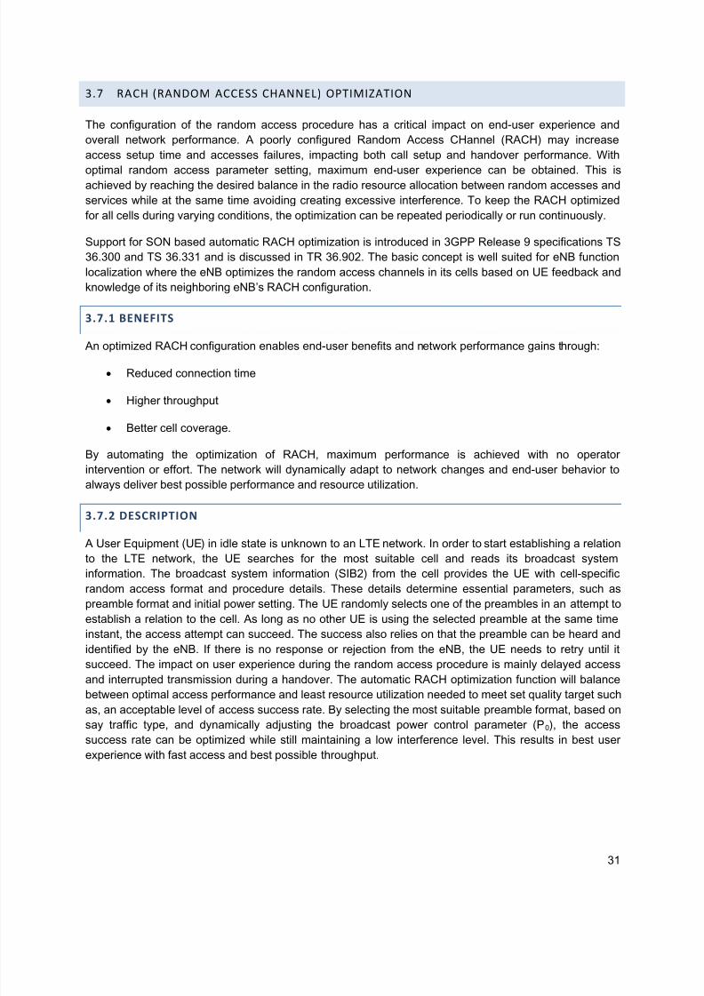
5/14/2018 Self Optimizing+Networks Benefits+of+SON+in+LTE July+2011 - slidepdf.com
http://slidepdf.com/reader/full/self-optimizingnetworks-benefitsofsoninlte-july2011
31
3.7 RACH (RANDOM ACCESS CHANNEL) OPTIMIZATION
The configuration of the random access procedure has a critical impact on end-user experience and
overall network performance. A poorly configured Random Access CHannel (RACH) may increase
access setup time and accesses failures, impacting both call setup and handover performance. With
optimal random access parameter setting, maximum end-user experience can be obtained. This isachieved by reaching the desired balance in the radio resource allocation between random accesses and
services while at the same time avoiding creating excessive interference. To keep the RACH optimized
for all cells during varying conditions, the optimization can be repeated periodically or run continuously.
Support for SON based automatic RACH optimization is introduced in 3GPP Release 9 specifications TS
36.300 and TS 36.331 and is discussed in TR 36.902. The basic concept is well suited for eNB function
localization where the eNB optimizes the random access channels in its cells based on UE feedback and
knowledge of its neighboring eNB’s RACH configuration.
3.7.1 BENEFITS
An optimized RACH configuration enables end-user benefits and network performance gains through:
Reduced connection time
Higher throughput
Better cell coverage.
By automating the optimization of RACH, maximum performance is achieved with no operator
intervention or effort. The network will dynamically adapt to network changes and end-user behavior to
always deliver best possible performance and resource utilization.
3.7.2 DESCRIPTION
A User Equipment (UE) in idle state is unknown to an LTE network. In order to start establishing a relation
to the LTE network, the UE searches for the most suitable cell and reads its broadcast system
information. The broadcast system information (SIB2) from the cell provides the UE with cell-specific
random access format and procedure details. These details determine essential parameters, such as
preamble format and initial power setting. The UE randomly selects one of the preambles in an attempt to
establish a relation to the cell. As long as no other UE is using the selected preamble at the same time
instant, the access attempt can succeed. The success also relies on that the preamble can be heard and
identified by the eNB. If there is no response or rejection from the eNB, the UE needs to retry until it
succeed. The impact on user experience during the random access procedure is mainly delayed access
and interrupted transmission during a handover. The automatic RACH optimization function will balance
between optimal access performance and least resource utilization needed to meet set quality target suchas, an acceptable level of access success rate. By selecting the most suitable preamble format, based on
say traffic type, and dynamically adjusting the broadcast power control parameter (P0), the access
success rate can be optimized while still maintaining a low interference level. This results in best user
experience with fast access and best possible throughput.

5/14/2018 Self Optimizing+Networks Benefits+of+SON+in+LTE July+2011 - slidepdf.com
http://slidepdf.com/reader/full/self-optimizingnetworks-benefitsofsoninlte-july2011
32
The automatic RACH optimization function can be executed continuously resulting in RACH related
parameters being modified automatically. The changes could be based on inputs from both the connected
UEs and each cell’s neighboring cells. By collecting the recently introduced RACH report from the UE, the
actual access delay can be determined. The RACH report is included in the message
UEInformationResponse (3GPP Rel-9 spec TS 36.331). It contains two new parameters:
numberOfPreamblesSent and contentionDetected. Based on this new information, the automatic RACH
optimization function can adjust the power control parameter (P0) or change the preamble format to reach
the set target access delay. By optimizing P0, the probability for an eNB to read the preamble increases.
However, as a result, the interference on neighboring cells may also increase. The second option adjusts
the preamble format to use, under the premise that a correct preamble format assures successful
preamble detection for the traffic type in a cell.
The automatic RACH optimization function automates the required continuous adaptation of the RACH.
The automatic RACH optimization function can automatically react when receiving notification over X2 of
a RACH parameter change in a neighboring cell. The information is transmitted via the eNB configuration
update X2 message. For instance, allocation of same root sequence index in neighboring cells should be
avoided to reduce interference. Automatic RACH optimization, based on the optimization on real traffic
data and neighbor cell information, makes it well suitable for eNB function localization. The automaticRACH optimization function can execute autonomously with no operator intervention or effort. The
operator controls the function with a few policies that set the outer limits for the function. These limits
assure that the function will not move to an extreme setting when finding the best tradeoff between
access delay and resource utilization.
3.8 INTER CELL INTERFERENCE COORDINATION
Reuse one cellular networks are characterized by mutual interference between cells. Given the
orthogonal nature of intra-cell transmissions, the source of interference in LTE is inter-cell interference.
Within the OFDM and SC-FDMA based LTE system interference has to be coordinated on the basis of
the physical resource blocks (PRBs). The ability to schedule users over variable portions of the carrier
bandwidth allows for inter-cell interference coordination techniques to be utilized which can shape the
interference in frequency.
Inter-Cell Interference Coordination involves the intelligent coordination of physical resources between
various neighboring cells to reduce interference from one cell to another. Each cell gives up use of some
resource in a coordinated fashion to improve performance especially for cell edge users which are
impacted the most by inter-cell interference. ICIC is accomplished as follows:
Users can be scheduled in units of a physical resource block (PRB) which is 180 KHz.
Neighbouring cells can coordinate which portions of the bandwidth are used in each cell and the
transmission powers across various frequency resource blocks.
Inter-cell interference can be reduced or avoided in uplink and downlink by a coordinated usage
of the available resources (PRBs) in the related cells which leads to improved SIR and
corresponding throughput. This coordination is realized by restriction and preference for the
resource usage in the different cells. This can be achieved by means of ICIC related RRM
mechanisms employing signalling of the following standards-defined metrics:
1. High Interference Indicator

5/14/2018 Self Optimizing+Networks Benefits+of+SON+in+LTE July+2011 - slidepdf.com
http://slidepdf.com/reader/full/self-optimizingnetworks-benefitsofsoninlte-july2011
33
2. Overload Indicator
3. Relative Narrowband Transmit Power (RNTP)
Exchanging the above information would allow an advantageous RRM resource usage by means of
preferences with respect to the e.g. available time/frequency resources, neighbourhood relations of the
cells and QoS requirements targeted by the operator.
Expected results of automated ICIC parameter settings include the automatic configuration or adaptation,
with respect to cell topology, of:
1. ICIC reporting thresholds/periods
2. Resource preferences in eNBs
3. RSRP threshold for ICIC
ICIC RRM might be configured by ICIC related configuration parameters like reporting thresholds/periods
and preferred/prioritized resources. Then these have to be set by the operator for each cell. Setting and
updating these parameters automatically is the task of a SON mechanism. The objective of SON is theself-configuration and self-optimization of control parameters of RRM ICIC schemes for uplink (UL) and
downlink (DL) ICIC. SON based ICIC requires the exchange of messages between the eNBs of various
cells, via X2 interface, for interference coordination. By means of ICIC related Performance
Measurements (PM) analysis, the SON function may properly tune ICIC configuration parameters like
reporting thresholds/periods and resource preference configuration settings in order to make the ICIC
schemes effective with respect to Operator’s requirements.
3.8.1 BENEFITS
Shaping the inter-cell interference allows an improved SINR to be realized in certain portions of the
spectrum. This can be exploited by the scheduler to provide an improved trade-off between sector
throughput and cell-edge bit rate. The result is improved SINR for cell edge UEs to achieve better edge
rates and cell throughputs, improved hand-off performance for cell edge UEs (Lower handoff delays and
lower handover failure rate) etc. The goal of SON based ICIC is to have minimized human intervention in
network management and optimization tasks.
3.8.2 DESCRIPTION OF ICIC OPERATION
Inter-cell interference coordination relies on intelligent resource allocation to eliminate interference. SON
aims to configure and optimize the network automatically, so that the need for manual intervention is
reduced and the capacity of the network can be increased by having it adapt to operating conditions
automatically as required for optimum performance. The capabilities provided by a SON fit very nicely
with the operational requirements for ICIC. ICIC requires that neighboring cells exchange informationabout which portion of the total bandwidth they are using. SON provides the ability for self-configuration
and self-optimization of which portion of the total bandwidth a particular cell will use. There are 3 basic
components to a SON ICIC implementation:
1. Core ICIC algorithm
2. Frequency planning

5/14/2018 Self Optimizing+Networks Benefits+of+SON+in+LTE July+2011 - slidepdf.com
http://slidepdf.com/reader/full/self-optimizingnetworks-benefitsofsoninlte-july2011
34
3. Inter-eNB communications
The core ICIC algorithms are those that determine how the resources (time, frequency and power)
available are managed to realize interference coordination between the cells. Various ICIC techniques
have been developed with varying degrees of performance and complexity.
In the downlink, the common theme of ICIC is to apply certain restrictions to the downlink resourcemanagement in a coordinated way between cells. The restrictions are distributed usually using the X2
connections to different cells during cell setup or when cells are de-activated and are generally constant
on a time scale corresponding to days. These restrictions determine the time/frequency resources
currently available to the Radio Resource Manager (RRM), as well as restrictions to the transmit power
that can be applied to certain time/frequency resources. These restrictions shape the interference power
spectrum of a given cell on the DL. The power constraints on the transmitted PRBs in one cell lead to
improved SINR and cell edge data rates/coverage for the corresponding time/frequency resources in a
neighbor cell.
Figure 9 shows the operation of one DL ICIC scheme known as the Inverted Reuse scheme. Three cells
are shown with each cell transmitting at a certain nominal power across the entire bandwidth except for a
restricted portion of the bandwidth. In the restricted PRBs, transmissions are either at a lower power,resulting in a soft partial frequency reuse scheme or there may not be any transmissions at all, resulting
in a hard partial frequency reuse scheme. Neighboring cells have restrictions in different portions of the
total bandwidth. A neighboring cell can schedule its cell edge users in the restricted PRBs of its neighbors
and realize an improved SINR since the neighboring cells are either transmitting with a lower power or not
transmitting at all on those PRBs. Users are classified into generally two groups: cell inner and cell edge
groups with the classification being made based upon a number or combinations of such metrics such as
a user’s serving cell path loss and differential path loss between that user’s serving and neighboring cells.
The performance of ICIC depends upon a number of factors such as cell size, cell load, propagation
channel, user mobility, traffic model, traffic type, etc.
In the uplink, it is the UEs near the cell border which cause most of the interference to adjacent cells. Thebasic concept in the UL is to concentrate the bulk of the inter-cell interference in a small portion of the
total bandwidth, thereby preventing any impact to the majority of users since the interference is now
localized to certain sub-carriers and the sub-carriers are orthogonal to each other.
5/14/2018 Self Optimizing+Networks Benefits+of+SON+in+LTE July+2011 - slidepdf.com
http://slidepdf.com/reader/full/self-optimizingnetworks-benefitsofsoninlte-july2011
35
DL PowerMask
•Information Exchange
over X2
DL PowerMask
•Frequency Sub-bands
•1
•2
•3
•x dB
1
•Frequency Sub-bands
•Frequency Sub-bands
Figure 9 - Inverted 1/7 Soft Re-use ICIC DL Scheme
3.8.3 FREQUENCY PLANNING
Static ICIC techniques require that every cell designates a certain portion of the bandwidth to be in some
kind of restriction. These restrictions correspond to the PRBs for the Interference Bearing Zone for the UL
and in the DL to those PRBs that are transmitted at a lower power. In addition, these restricted PRBs onboth the UL and DL should not overlap across neighboring cells. This is classic frequency planning. It is
desirable that this frequency planning be completely automated for LTE as operators do not want to deal
with the logistical complexity of manual frequency planning and deployment. Once a particular colour has
been assigned to a cell, each eNB informs its neighbours of its transmit PSD mask through RNTP
reporting over the X2 interface.
Some of the constraints of the frequency planning are:
1. Two neighbouring cells must have different colours.
2. As far as possible, a cell should not have two neighbours with the same colour.
3. Assign colours to cells such that same coloured cells are as far apart as possible.
3.8.4 SELF‐TUNING X2 INDEPENDENT ALGORITHMS
Self-tuning techniques, in the form of channel aware or interference aware packet schedulers, which treat
the problem of interference looking at the information available in the victim cell (i.e. CQI sub-band
reports, channel state information (CSI), or other eNB measurements), can achieve similar performance
without the need to implement X2 communication.

5/14/2018 Self Optimizing+Networks Benefits+of+SON+in+LTE July+2011 - slidepdf.com
http://slidepdf.com/reader/full/self-optimizingnetworks-benefitsofsoninlte-july2011
36
These techniques may create reuse patterns within the cell or allocate additional resources to improve
the performance of cell edge users, but the settings are adjusted automatically based on the
measurements within the cell, without need for external communication or control from centralized entity.
Autonomous and self-adjusting frequency re-use mechanisms may provide even greater benefits for
uncoordinated LTE deployments such as addition of femto and pico cells14
.
3.8.5 PERFORMANCE OF ICIC TECHNIQUES RELATIVE TO SELF‐TUNING X2 INDEPENDENT
ALGORITHMS
ICIC techniques typically improve cell edge user performance and provide significant gains on top of
basic packet scheduler. The gains from ICIC vary depending on the architecture, specific ICIC algorithm
and the scenario.
The performance of ICIC is dependent upon the ICIC algorithm used, and several other parameters such
as the propagation channel, user mobility, scheduling algorithms, cell size, cell load, traffic type, whether
the ICIC technique is static or dynamic in operation, metric types used to classify cell center versus cell
edge users, user distribution inside cell, etc. 3GPP does not specify the type of ICIC technique to be
used, allowing different vendors the freedom to implement different techniques. What is standardized
however are a set of metrics that can be exchanged used in the implementation of the ICIC technique.
Reuse 1 techniques, such as Frequency Selective or Channel Aware Scheduling, can also provide
performance similar to ICIC techniques in certain scenarios, such as for users at low user mobility and
when scheduling can be done every sub-frame. The availability of sub-band SINR information through
the use of narrow band channel quality indicators (NB-CQIs) on the downlink helps the Channel Aware
scheduler to mitigate interference quite well. Additionally, when working at fractional loads, reuse 1
schemes may allocate additional bandwidth to users at cell border to compensate for lower average
SINR. In this scenario, ICIC provides little to no gain over a channel aware scheduler. Furthermore, there
may be ICIC implementations where X2 communication delays reduce potential gains under realistic
scenarios since the feedback may not follow up with fast changing conditions of the interference and fastfading. In addition, requirements for X2 communication may cause problem in areas belonging to different
MME, and inter-vendor borders.
On the other hand, there are scenarios where ICIC may provide gains over a reuse 1 channel aware
scheduler, such as in uplink direction, for high user mobility and when Semi-Persistent Scheduling is
used. Dynamic ICIC schemes have been shown to provide even better performance compared to their
static counterparts. Finally, it has been shown that ICIC techniques provide good performance in
Heterogeneous Network scenarios where they are used to manage the interference from the macros into
the small cells.
To conclude, it is important to note that the performance of ICIC algorithm is closely tied to the specific
implementation. Latencies due to X2 signaling depend on the deployment architectures as well as theICIC algorithms themselves. In certain architectures, there may be no extra latency or complex signaling
required as information from multiple cells is readily available in a centralized processing site, without the
need for X2. Finally, there are ICIC algorithms that require less signaling support compared to others.
3.8.6 OPTIMIZATION OF COVERAGE/INTERERENCE WITH H‐ENB
Release 8 and Release 9 standards for Home eNBs did not provide any control mechanisms between the
HNB and the macro base stations. As result, there could be situations where potential DL/UL interference

5/14/2018 Self Optimizing+Networks Benefits+of+SON+in+LTE July+2011 - slidepdf.com
http://slidepdf.com/reader/full/self-optimizingnetworks-benefitsofsoninlte-july2011
37
is created between these two cells, or weak in-home coverage. Error! Reference source not found.10
illustrates the potential interference scenarios between a Home eNB and a macro cell.
Figure 10 - Potential Interference situations in a Macro-Home eNB interaction
With Release 8 and Release 9 mechanisms, in cases where the DL signal from the macro cell is low, the
HNB will typically adjust its power to prevent interference to other UEs in the network, resulting in a
weaker coverage for the home user; alternatively it can keep the transmit power up, which will result in
high interference to the macro BTS users at the cell edge that cannot camp on the HNB. Another problem
is the UL interference generated to the HNB from UEs that are connected to macro base stations, and are
not allowed to camp on the HNB (Right picture in Figure 10)). This in turn, can make the UEs that are
camping on the HNB to increase their UL power thus affecting the UL performance of the macro base
station.
NGMN has suggested a series of mitigation techniques for these problems that would require the
interaction between Home eNB’s and macro base stations.
UE Assisted DL Control
There are two different techniques proposed to improve the current power control mechanism in case of
HNB-macro BTS interaction. In the first approach namely, signaling of power down indication, the macro
BTS instructs the HNB to adjust its DL power after it receives multiple reports from different UE’s
indicating high interference from that HNB. The HNB will power up steadily after a certain time assuming
the interference situation has disappeared.
In the second approach, the macro BTS would forward the measurement report to the HNB in the case of
detected interference, thus providing the HNB with more detailed information from the interference
situation that would allow the HNB to balance the power considering the interfered UEs and its own
served users.
Fractional Frequency reuse
In case of high interference, the HNB and macro BTS can coordinate their schedulers to assign different
time/resource blocks for transmission to avoid co-channel interference, or to reduce the power in certain
blocks. To do this, the macro BTS would indicate to the HNB a set of resources that it would like to use
for the interfered UE, and the HNB would adjust their transmission patterns accordingly.

5/14/2018 Self Optimizing+Networks Benefits+of+SON+in+LTE July+2011 - slidepdf.com
http://slidepdf.com/reader/full/self-optimizingnetworks-benefitsofsoninlte-july2011
38
Partial co-channel deployment
While Fractional Frequency Reuse is effective in reducing interference to the data channels, by either
reducing power or totally eliminating transmission, it would not eliminate the interference on control
channels. With a partial co-channel deployment, the HNB can be allocated a small subset of the available
bandwidth for macro base stations to avoid high interference in the control channels. Such bandwidth
would be indicated by the macro base station to the HNB in case of interference situations.
Noise padding
The uplink interference from macro UEs, especially those at cell edge, can create serious problems to the
HNB. If the source of the interference is bursty, the rate prediction and error correction mechanisms in the
HNB will not work well. With this technique, the HNB will identify such interference situations and
temporarily increase the noise figure to compensate for this. In order to avoid UL power racing between
the macro and HNB UEs, the macro BTS would signal to the HNB a maximum noise figure, maximum
transmit power or overload indicator.
3.8.7 RELEASE‐10 ICIC ENHANCEMENTS
Dominant interference condition has been shown when Non-CSG/CSG users are in close proximity of
femto. In this case, Rel8/9 ICIC techniques are not fully effective in mitigating control channel
interference, and therefore enhanced interference management is needed.
Release 10 has introduced enhanced ICIC mechanisms. 3GPP has proposed candidate solutions for
Interference coordination for non-CA based heterogeneous networks focusing on macro-femto
deployment scenario and macro-pico scenario. Three different candidate solutions for eICIC are:
Time-domain solution – Subframe utilization (Almost Blank Subframes (ABS)) across nodes are
coordinated through backhaul signalling.
Power control solution – HeNB adjusts its transmit output power to avoid interference to other
nodes.
Frequency-domain solution – Orthogonal bandwidth for control signaling and common information
are configured across nodes.
3.9 ENERGY SAVINGS
Mobile network operators are increasingly aiming at decreasing power consumption in telecom networks
to lower their OPEX and reduce greenhouse emissions with network energy saving solutions for long
term sustainable development. With the expected deployment of large numbers of mobile network radio
equipment, in the form of Home NB/eNBs, OPEX reduction becomes even more crucial.
Energy consumption is a significant part of an operator’s OPEX. OPEX reduction can be accomplished by
designing network elements with lower power consumption and temporarily shutting down unused
capacity when not needed. Power amplifiers consume a significant portion of the total energy
consumption in a wireless network.

5/14/2018 Self Optimizing+Networks Benefits+of+SON+in+LTE July+2011 - slidepdf.com
http://slidepdf.com/reader/full/self-optimizingnetworks-benefitsofsoninlte-july2011
39
Currently network elements can only be put in stand-by mode using modems managed by separate tools.
For an integrated energy saving functionality, network elements should provide a stand-by mode with
minimum power consumption and a possibility to switch on and off this stand-by mode remotely via the
element management system without affecting the customer experience such as dropped calls.
Mechanisms to realize energy savings are being investigated in 3GPP.
3.9.1 BENEFITS
Sustainable development is a key criterion for telecom operators, to address the problems of resource
shortage and environmental deterioration due to greenhouse emissions. Energy saving mechanisms
allow operators to reduce OPEX and provide the quality of experience to end users with minimal impact
on the environment. The possibility to temporarily switch-off some parts of radio access network nodes,
such as a given Radio Access Technology (GSM, UMTS), will reduce the operational costs related to
power consumption.
3.9.2 DESCRIPTION
Energy savings by switching off/on cells can be initiated in several different ways as follows:
By the operator, from the OAM manager;
Setting policies and conditions that result in autonomous switching off/on cells when the
conditions are met;
Completely autonomous by the eNB with information exchanged on the X2, S1 interfaces.
When a cell is switched off, there may be a need for the neighboring cells to pick up the load. However
switching off a cell should not cause coverage holes or create undue load on the surrounding cells. A
switched off cell is not considered a cell outage or a fault condition. All traffic on that cell is expected to be
moved to the underlying umbrella cells before any switch off occurs.
When a NE is "switched off" for energy savings purposes, no alarms should be raised to the OAM
manager for a condition that is a consequence of a "switched off" NE. The operator should have the
capability to prevent the network from automatically compensating based on the cell that is in energy
savings mode in order to prevent unnecessary disruption in the network.
3GPP is examining solutions for energy saving in E-UTRAN, so that a subset of them can be used as the
basis for further investigation and standardization. The following use cases are considered:
Inter-RAT energy savings
Intra-eNB energy savings
Inter-eNB energy savings
In defining the various energy saving solutions, valid scenarios based on cell/network load situation,
impacts on legacy and new terminals when introducing an energy saving solution are considered. The
objective of the technical work in 3GPP energy saving management is to identify automated energy
savings management features. 3GPP addresses the following.

5/14/2018 Self Optimizing+Networks Benefits+of+SON+in+LTE July+2011 - slidepdf.com
http://slidepdf.com/reader/full/self-optimizingnetworks-benefitsofsoninlte-july2011
40
Select existing measurements which can be used for assessing the impact and effect of energy
saving actions corresponding to above energy saving use cases.
Define new measurements which are required for assessing the impact and effect of energy
saving actions, including measurements of the energy consumption corresponding to above
energy saving use cases.
3GPP has scoped that the following criteria should be met:
User accessibility should be guaranteed when a cell transfers to energy saving mode.
Backward compatibility and the ability to provide energy savings for Rel-10 network deployment
that serves a number of legacy UEs should be met.
The solutions should not impact the physical layer.
The solutions should not impact negatively the UE power consumption
Energy savings should not lead to service degradation or inefficiencies in the network since the activation
status of radio stations (on/off) introduces a new scale of dynamicity for the UE and network.
The increase in signaling potentially endangers the network stability and needs to be handled properly.
3.9.3 DEPLOYMENT SCENARIOS WITH LTE IN CLUSTERS, OVERLAYING AN UNDERLYING
2G/3G NETWORK
Initially, LTE will be deployed in clusters as an overlay for capacity enhancement at hot spots with an
underlying 2G/3G network.
Figure 11 - Inter-RAT energy saving scenario
In Figure 11, E-UTRAN Cells C through G are totally covered by the same legacy RAT Cell A and B (e.g.
UMTS or GSM). Cells A and B have been deployed to provide basic coverage of the services in the area,
while other E-UTRAN cells boost the capacity.
In such networks, the legacy network provides the basic coverage for those UEs with multi-mode
capability and the E-UTRAN only UEs are not served when they are out of the coverage of E-UTRAN.
The energy savings procedure can be enabled based on the interaction of E-UTRAN and UTRAN
system.

5/14/2018 Self Optimizing+Networks Benefits+of+SON+in+LTE July+2011 - slidepdf.com
http://slidepdf.com/reader/full/self-optimizingnetworks-benefitsofsoninlte-july2011
41
3.9.3.1 SOLUTIONS FOR CELL SWITCH ON/OFF IN INTER-RAT SCENARIO
Solution 1: Cell switch on/off via OAM commands: With this solution, an E-UTRAN cell can be switched
off/on by the centralized OAM system based on some RAN information, e.g. load information. The Intra-
RAT and Inter-RAT neighbor nodes should be informed either by the OAM or through signaling.
Solution 2: Cell switch on/off autonomously at the RAN node via local policies downloaded by OAM: Withthis solution, the E-UTRAN node can switch the cell on/off according to a certain policy configured by
OAM, and its Intra-RAT and Inter-RAT neighbor nodes should be informed, either by the OAM or by the
signaling. An example policy would be, switching on the cell 3 hours after switching it off, or switching off
the cell at 1:00 am and switching on it again at 7:00 am. As a part of energy saving operation, the E-
UTRAN node may first handover the capable UEs to the UTRAN/GERAN.
Solution 3: Cell switch on/off based on signaling across RATs: With this solution, the capacity boosting
E-UTRAN cell may be switched off autonomously based on information available in the cell. Switch-on
may be performed upon request by one or more neighbor inter-RAT nodes. Intra-RAT and Inter-RAT
neighbor nodes should be informed after on/off decision is made.
3.9.3.2 FURTHER ENHANCEMENTS FOR INTER-RAT SCENARIO
Issue:
Further enhancements need to be addressed for Inter-RAT scenarios. The reason is that when the E-
UTRAN cells are not active and the load increases, the legacy cells for coverage will not know which cell
should be woken up, especially when the increased load is in one or few hotspots.
Enhancements based on solution 3 to select the appropriate cells to activate include the following.
Solution 4: In this enhancement, when the load is heavy and some E-UTRAN cells need to be switched
on, those legacy cells for coverage will activate its dormant neighbors. After that, if some E-UTRAN cells
find that it could return to sleep mode, they can switch themselves off again.
Solution 5: In this enhancement, the listening capability of the E-UTRAN cells may be enabled
independently from other functions of the cell. In that case, the sleeping cells may monitor, when
requested, interference over thermal (IoT) ratio, which is obtained based on received interference power
and thermal noise power. When the legacy cells providing coverage detect high load, they may request
the E-UTRAN cells within their coverage to provide IoT measurements. The legacy cells could then
compare measurements reported from all the hotspots, including stored RSRP measurements from
served users. In most cases, the legacy cells will be able to find which E-UTRAN cells are the most
appropriate to serve the higher load. Accordingly, those legacy cells could activate the appropriate cells in
E-UTRAN while keeping other hotspot cells in sleep mode.
3.9.4 SCENARIOS FOR FURTHER STUDY
In later phases of LTE deployment, when operators deploy the LTE network without any 2G/3G overlay,
the application scenario for energy savings is as follows.

5/14/2018 Self Optimizing+Networks Benefits+of+SON+in+LTE July+2011 - slidepdf.com
http://slidepdf.com/reader/full/self-optimizingnetworks-benefitsofsoninlte-july2011
42
Figure 12 - Inter-eNB scenario 1 for energy saving
In Figure 12, E-UTRAN Cells C through G are totally covered by the E-UTRAN Cell A and B. Here, Cells
A and B has been deployed to provide basic coverage, while other E-UTRAN cells boost the capacity.
When some cells providing additional capacity are no longer needed, they could be switched off for
energy optimization. In this scenario, both the continuity of LTE coverage and service QoS could be
guaranteed.
3.10 CELL OUTAGE DETECTION AND COMPENSATION
Cell Outage Detection and Compensation provides automatic mitigation of eNB failures especially in the
case where the eNB equipment is unable to recognize being out of service and has therefore failed to
notify OAM of the outage. Detection and Compensation are two distinct cases that cooperate to provide
a complete solution:
Cell Outage Detection typically combines multiple separate mechanisms to determine whether an
outage has occurred. This is needed to detect the latent fault case, often described as “Sleeping Cell”,
where OAM is unaware of the issue. If a cell continues transmitting but does not accept RACH access or
hand-ins, it will simply generate interference. The most immediate mitigation available is to stop that cellfrom transmitting. OAM aspects are addressed in detail in 3GPP 32.541.
Cell Outage Compensation techniques are generally only applied after standard soft recovery
techniques have failed to restore normal service.
3.10.1 BENEFITS
Detection and Compensation provide distinct benefits to the Operator. Previous generations of cellular
infrastructure have experienced failures of which Operators had no knowledge until such time as
receiving notification from customer support of problems in the field. Cell Outage Detection ensures that
the operator knows about the fault before the end user does.
Cell Outage Compensation provides temporary alleviation of the problem caused by the loss of a Cell
from service. Compensation mode alleviates the outage, but the level of service provided to users in the
affected area is likely to be restricted by local topology, distance from neighboring serving cells and
available capacity.

5/14/2018 Self Optimizing+Networks Benefits+of+SON+in+LTE July+2011 - slidepdf.com
http://slidepdf.com/reader/full/self-optimizingnetworks-benefitsofsoninlte-july2011
43
3.10.2 CELL OUTAGE DETECTION
Cell Outage Detection uses a collection of evidence and information to determine that a cell is no longer
working correctly. Detection includes active notification to cover the generalized case in which OAM is
aware of the fault.
In the case of complete eNB failure, OAM will be unable to communicate with the eNB to determine
whether its cell is in service. Lack of communication could be a symptom of failure on the OAM Backhaul
rather than an indication that the site is down. In this case, the Network Manager needs to have other
evidence to determine the nature of the problem. If the cell is still in service, it will continue to interact
with the core network, so the Network Manager should be able to determine from core network metrics
whether there is ongoing interaction with a specific eNB or cell.
Latent fault determination is the term used when the fault detection is based on evidence, such as
anomaly statistics, rather than an alarm or state change. This is the most challenging of the Cell Outage
Detection scenarios since OAM indications will suggest that it continues to operate normally. This type of
detection may be achieved with a combination of statistics and activity watchdog timers. The operator will
typically have a set of generic policies defined where each policy describes the combination of stats or
events that are deemed to indicate a Cell Outage. This may be enhanced using a set of “Cell Type”
specific rules where all cells of a specific type use a separate or additional policy. Perhaps the most
valuable of the evidence based detection mechanisms, is the use of time / day profiling on a per cell
basis. This is achieved by collecting stats over a period of time and gradually building a statistical picture
of expected performance for a given time of day, weekday, or weekend. When stats collected for a cell
deviate significantly from values normally seen for that cell, then there is a likelihood of a latent fault.
3.10.3 CELL OUTAGE COMPENSATION
Before considering the many complex reconfigurations available to ensure that neighboring cells provide
service in the area affected by cell outage, it is important to understand that in most urban cases, the
majority of external users are likely to have at least a minimum level of service from those neighboringcells even without any reconfiguration.

5/14/2018 Self Optimizing+Networks Benefits+of+SON+in+LTE July+2011 - slidepdf.com
http://slidepdf.com/reader/full/self-optimizingnetworks-benefitsofsoninlte-july2011
44
Figure 13 - Outage compensation scenario
In the example of Figure 13, eNB 1(sector B) is experiencing an outage. Note that there is significant
overlap both from eNB 1(sectors A and C), and also from eNB 3(sector A) and eNB 2(sector C). These
cells will experience slightly improved performance at their cell edges due to the removal of interference
from eNB 1(sector B).
Typically, tilt based compensation would be limited to facing sectors, i.e. eNB 2(sector C) and eNB 3
(sector A) since tilt generally has the greatest coverage impact at boresight and the least impact on the
borders with co-sited neighbors. Therefore, tilting eNB 1(sectors A and C), is likely to do more harm than
good.
There are three main areas that need to be addressed in trying to improve on the existing default Cell
overlap.
1. Neighbors
With a given cell out of service, it is essential that neighboring cells on opposite sides of the
outage are configured as neighbors. In most cases, this relationship is likely to exist by default,
since most neighbor planning, both manual and automatic, tends to include a second ring ofneighboring cells and not just those on the immediate border. It may also be advantageous to
enable the Automatic Neighbor Relationships use case (ANR) on cells surrounding the outage to
ensure that no essential relationships are missed. In most cases, neighbors that are added to
enable support of a neighboring cell outage will not subsequently need to be deleted after normal
service has been restored.

5/14/2018 Self Optimizing+Networks Benefits+of+SON+in+LTE July+2011 - slidepdf.com
http://slidepdf.com/reader/full/self-optimizingnetworks-benefitsofsoninlte-july2011
45
2. Physical Layer Cell Identities (PCIs)
The implicit change in neighbor relationships in the case of an outage, also requires a recheck of
the rules relating to PCIs.
A cell and its neighbor must not have the same PCI.
Neighbors of a given cell must not share the same PCI.
By revalidating the PCIs in the same way that the operator used to recheck the neighbors, one
can ensure that neither of these rules is broken. As in the case for new neighbors, it is generally
advantageous to plan PCI allocation for worst case as represented by a cell providing coverage
for a neighbor’s outage.
3. Coverage Footprint
There are three methods for adjusting a cell’s coverage footprint:
a. Handover Parameter offsets
It is possible within limits to adjust a cell’s handover boundary with an immediate
neighbor through change of cell individual offsets (CIO) or similar parameters, howeverthis has no relevance in the case of adjusting coverage in the direction of a Cell Outage.
b. Transmit Power
Transmit power has an immediate impact on the cell boundary, however, most cell
planning makes maximum use of available power, leaving very little positive headroom to
enable a cell to increase its coverage in the direction of a neighboring outage.
c. Antenna adjustment
Most discussions on cell outage coverage adjustment focus on change of antenna
pattern to achieve the additional coverage for the neighbor. In most cases, changes are
achieved with antenna tilt, i.e. alteration of the vertical pattern. However, newer antenna
technology enables many complex adjustments of the coverage pattern on demand.
There are industry collaborations between Radio Planning Tool vendors and Antenna
manufacturers in which Beam-Shaping adjustment is guided by data from the Radio
Planning Tool. The Antenna Interface Standards Group (AISG) has defined Standards for
tilt and Azimuth steering. These are consistent with the 3GPP standards for Remote
Electrical Tilt (RET) antennas: (TS 25.460 - TS 25.463). AISG has already been
deployed in some 2G and 3G networks, but is expected to be more widely deployed for
LTE.
The real challenge with use of antenna pattern adjustment in support of any SON
features, is ensuring there is a control loop to guarantee that antenna adjustment to
improve coverage in one area, doesn’t either worsen coverage or create too muchinterference in another area. SON needs to collect sufficient measurements to profile the
impact of antenna pattern adjustment. The goal for SON is to converge to a point where
a cell outage results in each of the surrounding cells adjusting their patterns by an
amount that is preconfigured for that specific neighbor relationship to shrink the coverage
hole that was created.

5/14/2018 Self Optimizing+Networks Benefits+of+SON+in+LTE July+2011 - slidepdf.com
http://slidepdf.com/reader/full/self-optimizingnetworks-benefitsofsoninlte-july2011
46
Figure 14 - Roles of Cell Outage Detection, Fault Management and Cell Outage Compensation
Figure 14 represents the generalized case of Cell Outage Detection and Compensation. It separates the
roles of Cell Outage Detection, Fault Management (FM) and Cell Outage Compensation. The specific
details will vary significantly between implementations. However, it is expected that detection would be
based on the following generic data to address those cases where the RAN OAM path is down but the
Network Elements are functional:
FM information for conventional alarmed failures;
Statistics for detection of latent fault conditions;
Neighbor reports to help detect latent failures, and
Core statistics to catch those cases where the RAN OAM path is down but the Network Elements
remain functional.

5/14/2018 Self Optimizing+Networks Benefits+of+SON+in+LTE July+2011 - slidepdf.com
http://slidepdf.com/reader/full/self-optimizingnetworks-benefitsofsoninlte-july2011
47
Cell Fault conditions are passed to normal FM procedures. Some vendors or operators may choose to
do this manually. Cell Outage Compensation technique is utilized when a fault cannot be resolved
remotely in a few minutes. During Cell Outage Compensation, SON will continue to monitor the impacted
cell and once advised that it is ready for service, it will re-initialize the cell and back out the compensation.
3.11 COVERAGE AND CAPACITY OPTIMIZATION
3.11.1 MODIFICATION OF ANTENNA TILTS
A typical operational task in wireless networks is to design and optimize the network according to
coverage and capacity. Traditionally, this has been performed based on measurements from the network
and using theoretical propagation models in planning tools. It requires extensive data collection from the
network including statistics and measurements, such as using extensive drive tests. In current networks,
while this task has been semi-automated with the help of Automatic Cell Planning tools, this method is still
largely based on measurement estimations. Therefore their results are not very accurate. Furthermore,
running such tools is a cumbersome task that requires a significant preparation on the operator side to
compile all necessary data inputs, create optimization clusters, and then implement the changes in the
network.
Coverage and Capacity Optimization (CCO) has been identified as a key area in 3GPP as a self-
optimization use case for SON, which will complement traditional planning methods by adjusting the key
RF parameters (antenna configuration and power) once the cells have been deployed. This method will
permit the system to periodically adjust to modifications in traffic (load and location) in addition to any
changes in the environment, such as new construction, or new cells being put on air.
The CCO function should work on a rather long time-scale in the order of days or weeks to capture and
react to long-term changes in physical environment, load imbalance, and UL/DL mismatch. Sufficient data
should be collected for accurate observation and estimation of CCO performance. The CCO
standardization is addressed in 3GPP Rel-10 and will continue to be addressed in Rel-11 and beyond.
3.11.1.1 BENEFITS
Self-optimization of coverage and capacity reduces manual operational tasks, resulting in OPEX
reduction and user QoE improvement. The feature will provide optimal coverage where LTE system is
offered. Thereby, users can establish and maintain connections with acceptable service quality, according
to operator’s requirements. This feature will provide optimal capacity where LTE system is offered
according to operator’s policy setting. Since coverage and capacity are linked, a trade-off between the
two of them would be dependent on optimization criteria.
5/14/2018 Self Optimizing+Networks Benefits+of+SON+in+LTE July+2011 - slidepdf.com
http://slidepdf.com/reader/full/self-optimizingnetworks-benefitsofsoninlte-july2011
48
3.11.1.2 DESCRIPTION
The term Coverage and Capacity Optimization (CCO) is very generic and covers a broad range of use
cases. In reality, many of the SON use cases defined in 3GPP are somehow related to a
coverage/capacity optimization effort such as, Cell Outage Compensation, Mobility Load Balancing and
the Interaction between Home and Macro eNB. As defined by 3GPP, the CCO use case is understood asautomatic cell planning, in which the SON algorithm has to find the optimum antenna and RF parameters
for the sectors that serve a certain area for a particular traffic situation. The optimum result should
maximize network throughput/capacity while complying with a certain service confidence level, as
specified by the operator.
The objective of the CCO use case as defined in RAN ( 3GPP TR 36.902) is to provide optimal coverage
and optimal capacity. The 3GPP TR 36.902 defines coverage and capacity as follows:
“In the area, where LTE system is offered, users can establish and maintain connections with acceptable
or default service quality, according to operator’s requirements. It implies that the coverage is continuous
and users are unaware of cell borders. The coverage must be provided in both, idle and active mode for
both, UL and DL. While coverage optimization has higher priority than capacity optimization in Rel-9, thecoverage optimization algorithms must take the impact on capacity into account. Since coverage and
capacity are linked, a trade-off between the two of them may also be a subject of optimization.”
The term “coverage” could mean coverage of basic service or coverage of user services. Basic service
includes reception of DL control channels and setting up a signaling radio bearer. User services refer to
services such as speech, video telephony, etc.
The term “capacity” could have various interpretations. There are several options for capacity, e.g., cell
throughput, median user throughput, xth-percentile cell edge throughput, and number of served users
(with a specific service or bit rate requirement).
There is a tradeoff between coverage and capacity. Typically, increasing the coverage results in less
spectral efficiency due to deteriorating signal power, resulting in less capacity. One cannot optimize both
coverage and capacity at the same time, and therefore there is a need to balance and manage the
tradeoff between the two.
The self-optimizing CCO function is a continuously running process which continuously gathers
measurements and takes actions, if needed. The operator can specify the desired performance
optimization target and the balance between different targets to achieve tradeoffs. Measurements and
reports from the network are used by CCO to estimate entities related to coverage and capacity
according to the target given by the operator. Minimization of Drive Test reports may be used to monitor
and detect coverage problems in the network.
CCO corrective actions comprise changes in radio parameters such as, antenna tilt and UL power control
parameters. Deployment of pico cells or coverage/capacity enhancing features are also corrective actions
that may be proposed by CCO to reach desired target. The CCO should not react to performance of
individual users, but rather compute appropriate CCO actions based on long-term statistics.

5/14/2018 Self Optimizing+Networks Benefits+of+SON+in+LTE July+2011 - slidepdf.com
http://slidepdf.com/reader/full/self-optimizingnetworks-benefitsofsoninlte-july2011
49
As with other aspects of SON development, it is expected that coverage and capacity optimization
techniques will change over time, adapting to the maturity level of the networks. In the initial stages of
commercial LTE network operation, traffic load will not be a major concern, and it is expected that there
will be coverage challenges due to lack of sufficient cell density or configuration errors. Therefore, CCO
techniques will primarily be focused around providing service coverage with a certain minimum quality.
The coverage area and capacity of a network, or some cells in the network, may vary due to addition ofbase stations, malfunctioning base stations, or change in user distribution. Suboptimal coverage area and
capacity leads to inefficient use of network resources and lower quality. Furthermore, adapting to network
changes manually is very expensive and time consuming. Thus, the CCO function operates continuously
to gather measurements and takes actions if needed. CCO should be a slow activity where statistics and
measurements are used as basis for decision.
3GPP TS 32.521 specifies the following requirements on CCO:
Coverage and capacity optimization shall be performed with minimal human intervention.
Operator shall be able to configure the objectives and targets for the coverage and capacity
optimization function.
Operator shall be able to configure the objectives and targets for the coverage and capacity
optimization functions differently for different areas of the network.
The collection of data used as input into the coverage and capacity optimization function shall be
automated to the maximum extent possible and shall require minimum possible amount of
dedicated resources.
The 3GPP specifications provide a set of use cases that the CCO function should cover. These use
cases are defined in a very generic manner, and simply indicate that the system should have functionality
that addresses these particular issues, without providing further guidelines. The following sections
describe the specified scenarios.
3.11.1.3 USE CASE1: E-UTRAN COVERAGE HOLES WITH 2G/3G COVERAGE
Consider the scenario in Figure 15 (left), in which an LTE network has been deployed on top of a legacy
2G or 3G network with a suboptimal RF and radio resource parameter configuration. Even if the LTE
coverage area is not contiguous, continuity of calls will be maintained due to inter radio access
technology handovers that allows the various RF carriers to be treated as a pooled resource. This
situation may not always be desirable in order to avoid unnecessary handovers that may lead to dropped
calls. Therefore, one objective of the CCO algorithm could be to try and minimize the coverage holes by
expanding the LTE footprint as illustrated in Figure 15 (right).
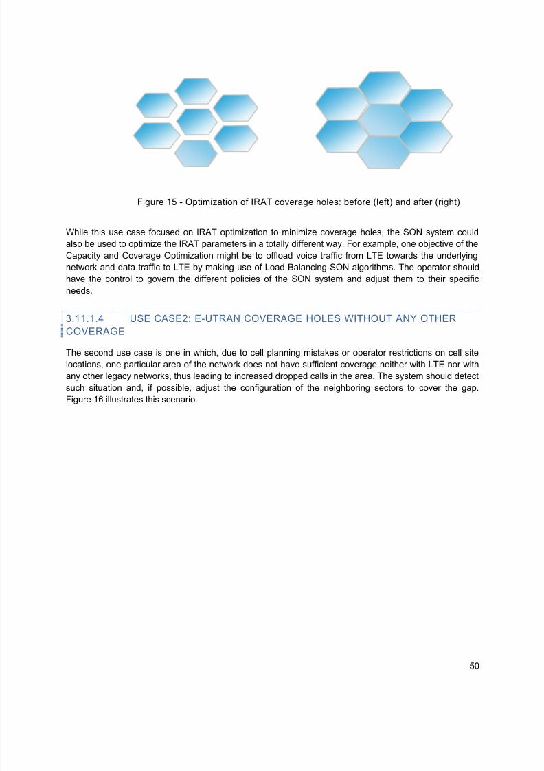
5/14/2018 Self Optimizing+Networks Benefits+of+SON+in+LTE July+2011 - slidepdf.com
http://slidepdf.com/reader/full/self-optimizingnetworks-benefitsofsoninlte-july2011
50
While this use case focused on IRAT optimization to minimize coverage holes, the SON system could
also be used to optimize the IRAT parameters in a totally different way. For example, one objective of the
Capacity and Coverage Optimization might be to offload voice traffic from LTE towards the underlying
network and data traffic to LTE by making use of Load Balancing SON algorithms. The operator shouldhave the control to govern the different policies of the SON system and adjust them to their specific
needs.
3.11.1.4 USE CASE2: E-UTRAN COVERAGE HOLES WITHOUT ANY OTHER
COVERAGE
The second use case is one in which, due to cell planning mistakes or operator restrictions on cell site
locations, one particular area of the network does not have sufficient coverage neither with LTE nor with
any other legacy networks, thus leading to increased dropped calls in the area. The system should detect
such situation and, if possible, adjust the configuration of the neighboring sectors to cover the gap.
Figure 16 illustrates this scenario.
Figure 15 - Optimization of IRAT coverage holes: before (left) and after (right)

5/14/2018 Self Optimizing+Networks Benefits+of+SON+in+LTE July+2011 - slidepdf.com
http://slidepdf.com/reader/full/self-optimizingnetworks-benefitsofsoninlte-july2011
51
3.11.1.5 USE CASE3: E-UTRAN COVERAGE HOLES WITH ISOLATED ISLAND
COVERAGE
This scenario covers the case in which operators are deploying LTE systems with islands of coverage as
opposed to contiguous coverage in one region. However, due to poor RF planning, the deployed network
may fall short of the designed footprint. In this case, the LTE network coverage should increase only in
those areas where there is a mismatch with the original plan, as shown in Figure 17.
Figure 16 - Illustration of coverage gap optimization: before (left) and after (right)
Planned coverage
area
Figure 17 - Isolated island coverage optimization

5/14/2018 Self Optimizing+Networks Benefits+of+SON+in+LTE July+2011 - slidepdf.com
http://slidepdf.com/reader/full/self-optimizingnetworks-benefitsofsoninlte-july2011
52
3.11.1.6 USE CASE4: E-UTRAN COVERAGE HOLES WITH OVERLAPPING
SECTORS
This scenario covers the case in which an operator adds new sectors, for capacity reasons, to an area
with existing coverage. In order to optimize the capacity of the cluster, the existing sectors need to
readjust their footprint to avoid excessive interference into the target area.
The figure below illustrates this scenario, in which a new site (shown in red on the left side of Figure 18) is
introduced in an area with existing LTE coverage. In this case, the new site and the surrounding eNB
need to automatically adjust their antennas and power to minimize interference in the area, while
maintaining the service coverage (Figure 18: right).
There are currently a very limited number of specific CCO scenarios mandated by 3GPP. However, giventhe amount of available information available to the SON system both from the UEs and the eNBs, and
increased flexibility of the network with the development of active antennas, CCO techniques will continue
to evolve to establish finer tradeoffs between coverage and capacity in more mature networks.
As an example, Figure 19 illustrates one potential usecase in which the different sectors adjust their
antenna orientation and transmit power to optimally capture UE traffic at different locations (shown in red)
while minimizing the interference to other cells. Such method will be invaluable to network operators,
since the location of the sectors is often constrained, and complicated network designs are required to
serve the existing traffic optimally.
Figure 18 - Optimization of coverage with newly added capacity sites

5/14/2018 Self Optimizing+Networks Benefits+of+SON+in+LTE July+2011 - slidepdf.com
http://slidepdf.com/reader/full/self-optimizingnetworks-benefitsofsoninlte-july2011
53
3 . 1 1 . 2 M I NI M I Z ATI O N OF DR I VE T E S T S
Traditional drive test procedures to determine coverage for various locations is expensive in terms of
staff, time and equipment needed. Since data can be obtained only for those locations where the drive
test is conducted, there is limited measured information for actual user distribution and their mobility and
application mixes. Lack of information from within in buildings leads an operator to make assumptions
about building path loss that may not correlate to the actual building path loss in a given region. Finally, a
manual correlation and post processing of drive test data with network parameters including transmit
power, antenna azimuth/tilt/gain, is needed in order to derive meaningful information.
Due to the various above limitations of using drive tests for network optimization purposes is expensive, it
is desirable to develop automated solutions, including involving UEs in the field to reduce the operator
costs for network deployment and operation. The concept of Drive Test (DT) substitution is to use actual
UE data to substitute for DT to help measure coverage vs. position, etc. In addition, UE data can in some
areas improve upon conventional DT by helping measure dropped calls versus position. Furthermore,
coordinated acquisition of UE and network data provides significant potential for surpassing DT in a more
fundamental way. 3GPP has concluded that it is feasible to use control plane solutions to acquire the
information from devices. This information, together with information available in the radio access network
can be used for Coverage and Capacity Optimization.
3.11.2.1 BENEFITS
The MDT data reported from UEs may be used to monitor and detect coverage problems in the network.Some examples of use cases of coverage problem monitoring and detection include the following.
Coverage hole: A coverage hole is an area where the signal level SNR (or SINR) of both serving
and allowed neighbor cells is below the level needed to maintain basic service (signaling radio
bearer (SRB) & DL common channels). Coverage holes are usually caused by physical
obstructions such as new buildings, hills, or by unsuitable antenna parameters, or just inadequate
RF planning. An UE in a coverage hole will suffer from call drop and radio link failure. Multi-band
and/or Multi-RAT UEs may go to another network layer instead.
Figure 19 - Example of CCO based on traffic location

5/14/2018 Self Optimizing+Networks Benefits+of+SON+in+LTE July+2011 - slidepdf.com
http://slidepdf.com/reader/full/self-optimizingnetworks-benefitsofsoninlte-july2011
54
Weak coverage: Weak coverage occurs when the signal level SNR (or SINR) of serving cell is
below the level needed to maintain a planned performance requirement (e.g. cell edge bit-rate).
Pilot Pollution: In areas where coverage of different cells overlap a lot, interference levels are
high, power levels are high, energy consumption is high and as a result, cell performance may be
low. This phenomenon is called “pilot pollution”, and the problem can be addressed by reducing
coverage of cells. Typically in this situation, UEs may experience high SNR to more than one cell
and high interference levels.
Coverage mapping: There should be knowledge about the signal levels in the cell areas in order
to get a complete view for the coverage and be able to assess the signal levels that can be
provided in the network. This means that there should be measurements collected in all parts of
the network, and not just in the areas where there are potential coverage issues.
UL coverage: Poor UL coverage might impact user experience in terms of call setup failure / call
drop / poor UL voice quality. Therefore, coverage should be balanced between uplink and
downlink connections. Possible UL coverage optimization comprises adapting the cellular
coverage by changing the site configuration (antennas).
3.11.2.2 DESCRIPTION OF MDT REPORTING MODES
The general principles and requirements guiding the definition of functions for Minimization of Drive Tests
are described in this section. There are two modes of reporting for the MDT measurements: non-real-time
or immediate reporting.
Immediate MDT refers to MDT functionality involving measurement performance by UE in
connected/active state and reporting of the measurements to eNB/RNC available at the time of
reporting condition.
Logged MDT refers to MDT functionality involving measurement performance by UE in idle state at
points in time when configured conditions are satisfied. This measurement log is reported to the eNB
at a later point in time when the UE goes into connected mode.
A UE in connected mode is configured with Immediate MDT that implies immediate reporting. A UE
in idle mode of operation is configured with Logged MDT. After having initiated Logged MDT, the UE
will not immediately report the data to the eNB. Key requirements for MDT include the following.
1. UE measurement configuration
The operator should be able to configure MDT measurements for the UE logging purpose
independently from the network configurations for normal RRM purposes.
2. UE measurement collection and reporting
It should be possible for measurement logs to consist of multiple events and measurements taken
over time. The time interval for measurement collection and reporting shall be separately
configurable in order to limit the impact on the UE battery consumption and network signalling
load. It shall be possible to collect measurements logs preceding a particular event (e.g. radio link
failure).
3. Geographical scope of measurement logging
It should be possible for the operator to configure the geographical area where the defined set of

5/14/2018 Self Optimizing+Networks Benefits+of+SON+in+LTE July+2011 - slidepdf.com
http://slidepdf.com/reader/full/self-optimizingnetworks-benefitsofsoninlte-july2011
55
measurements shall be collected. Some measurements might run independent of any
geographically defined area.
4. Location information
The measurements should be linked to available location information and/or other information or
measurements that can be used to derive location information.
5. Time information
The measurements in measurement logs should be linked to a time stamp.
6. Device type information
The terminal used for MDT should indicate a set of terminal capabilities which allows the network
to carefully select the right terminals for specific MDT measurements.
The solutions for MDT take into account the following constraints.
1. UE measurements
The UE measurement logging mechanism is an optional feature. In order to limit the impact on
UE power consumption and processing, the UE measurement logging should as much aspossible rely on the measurements that are available in the UE according to radio resource
management enforced by the access network.
2. Location information
The availability of location information is subject to UE capability and/or UE implementation.
Solutions requiring location information should take into account power consumption of the UE
due to the need to run its positioning components.
Measurements supported for Immediate MDT performance include:
RSRP and RSRQ measurement by UE with periodic, event A2, or Radio Link Failure as reporting
triggers.
Power Headroom (PH) measurement by UE
Uplink signal strength/SINR measurement by eNB
The measurement quantity for Logged MDT consists of both RSRP and RSRQ for E-UTRAN.
MDT measurement collection task may be initiated in two distinct ways.
Management based MDT task is sent from the OAM towards a PLMN or a limited region within a PLMN
(limited by a cell list, a TA list, a LA list or a RA list) without targeting a specific UE.
Signaling based MDT task is sent from the OAM and initiated towards a specific UE and a PLMN or a
limited region within a PLMN (limited by cell list, a TA list, a LA list or a RA list) by the signaling trace
activation messages from core network nodes.
Management based MDT and Signaling based MDT capabilities are specified in 3GPP TS 32.421,
TS 32.422 and TS 32.423.

5/14/2018 Self Optimizing+Networks Benefits+of+SON+in+LTE July+2011 - slidepdf.com
http://slidepdf.com/reader/full/self-optimizingnetworks-benefitsofsoninlte-july2011
56
3.12 APPLICATIONS OF SON TO ADDRESS DEPLOYMENT AND OPERATION OF DAS AND
SMALL CELLS
3.12.1 SON INTERACTIONS WITH DISTRIBUTED ANTENNA SYSTEMS
LTE macro base stations can provide high data rates when higher modulation schemes are used inconjunction with high signal to noise ratios. Macro eNBs can provide high signal to noise ratios but only
with high power levels on the downlink and addition of tower mounted amplifier on the uplink. Even then
extreme care must be taken to make sure the extra power does not pose interference to other sites.
Another approach to solving this issue would be to install a Distributed Antenna System (DAS) whereby
the signal source is brought to within a few hundred feet of the users while the interference remains
unchanged. Hence, signal to noise ratio improves substantially allowing for higher data rates without a
significant increase in power levels.
SON functionality is typically geared towards managing base stations (macro, pico or femto) in cellular
networks. Distributed Antenna System (DAS) coverage solution networks are often provided by vendors
besides the vendors providing the RAN. These coverage solution networks are often managed by an
EMS separate from that managing the RAN. Consequently, the performance input from RAN is not
readily available to the coverage solution networks. Therefore, the full extent of the SON benefits is not
afforded to coverage solution networks. Further, each host eNB may host multiple DAS nodes but is
unaware of the hosting relationship. SON functionality relating to optimization relies on Key Performance
Indicators (KPIs) to tune the network for optimal coverage, capacity or performance. However, it is difficult
to associate performance statistics to a specific DAS node coverage area.
To overcome these issues, the following options should be explored:
Develop a coordination mechanism between coverage solution network EMS and RAN EMS.
Develop a mechanism that provides a host eNB visibility into whether it is deployed as a DAS
network host.
Develop a mechanism to facilitate communication between the host eNB and the DAS node(s).
Such mechanisms could allow the operators to provide solutions such as:
Adjust coverage under overload conditions to drive hand-off of traffic to unloaded DAS sectors
especially in stadiums and convention centers.
Offload traffic from cellular network to WiFi network under overload conditions.
3.12.2 SON WITH PICOS/FEMTOS/RELAYS
With the data explosion observed in the last years, and the forecasted continuous growth in data traffic
even LTE networks will suffer capacity constraints as the radio link spectral efficiency approaches its
theoretical maximum Shannon limits. One way to increase spectral efficiency is to provide methods to
serve the traffic closer to where it is originated, making sure that the available SINRs is always high and
the system can operate using the best possible modulation and channel protection scheme, operating at
a lower transmit power level. Such a paradigm will result in heterogeneous networks where a variety of
base station transmitters will be used to flexibly accommodate the high traffic demand in different
environments: home/office, dense hotspots, isolated high-demand areas, etc.

5/14/2018 Self Optimizing+Networks Benefits+of+SON+in+LTE July+2011 - slidepdf.com
http://slidepdf.com/reader/full/self-optimizingnetworks-benefitsofsoninlte-july2011
57
There are a variety of base stations available today for LTE and other technologies as follows.
Micro or pico cells are designed to serve hotspots within a macro cell without causing additional
interference. Their typical cell radius is one order of magnitude less than the macro cell by a
factor of 10. These units operate at a lower power than regular eNBs but would have similar
functionality and would require installation by the operator.
Home eNode-B (HeNBs) or femto cells are designed to cover few customers, typically in a home
or small office environment, using a transport method provided by the customer such as cable,
ADSL, etc.
Relays or repeaters provide a flexible method to cover weak coverage areas and increase
capacity with minimum installation costs, since they use the wireless network spectrum for
backhaul transmission.
Strictly speaking, these units are not new to the industry and have been in use with previous network
technologies. However LTE has taken special note of them during the specification phase to be able
provide a fully functional heterogeneous network. NGMN and 3GPP have recognized that heterogeneous
networks can result in a significant operational complexity increase for carriers and is actively working inspecifying methods to provide a smooth integration of the different units into the macro network and
simplify their operation.
Examples of specific SON considerations for heterogeneous networks can be found in the Automatic
Neighbor relation requirements indicated by NGMN, in which ANR mechanisms must be made aware of
the type of base station during the procedure. This allows the system to make the appropriate handover
between macro and micro cells based on UE speed and cell capacity.
One important focus area of SON is the support of HeNBs, for which multiple requirements have been
identified to improve the integration and interference management with the macro cell. Rel-10 3GPP
specifications provide standardized interfaces and OAM for the HNB to ensure a successful HNB self-
configuration installation in a multi-vendor environment. The specifications also provide a referencemanagement architecture with standardized information elements to facilitate the remote control of the
units by the operators. In addition, NGMN is actively working on proposals to improve the integration of
the units in the network causing minimal impact to the surrounding base stations, by providing methods to
automatically control the level of interference generated by non-coordinated HNB deployments. These
methods have led to standardization in 3GPP Rel-10, as described in Section 3.8.7, and will be continued
in Release 11.
3.12.3 USING SON TO FACILITATE THE DEPLOYMENT OF REPEATERS/RELAYS
Repeaters and Relays are nodes that retransmit the data transmitted by a macro cell: repeaters receive a
signal and amplify it, including the wanted signal and the interference, while relays are more sophisticated
and are able to receive the wanted data and retransmit it.

5/14/2018 Self Optimizing+Networks Benefits+of+SON+in+LTE July+2011 - slidepdf.com
http://slidepdf.com/reader/full/self-optimizingnetworks-benefitsofsoninlte-july2011
58
Figure 20 - Role of relays in providing additional coverage or capacity
Both repeaters and relays can be very useful for operators that need to bring additional coverage or
capacity to specific areas with a smaller investment since there is no separate backhaul required to
provide service. On the other hand, the deployment of these units in some situations may create more
problems than actually improving the coverage or capacity of the network. The use of Self-Organizing
Networks can help mitigate these problems with automated solutions in the following areas:
Automatic site selection
Automatic parameter configuration
Interference coordination
Self-healing (cell outage detection and compensation)
Resource sharing
Load balancing
Handover optimization
These items are candidate features to be addressed in subsequent releases of 3GPP. As LTE networks
mature and relays become more relevant, SON techniques will likely be developed to facilitate their
deployment.

5/14/2018 Self Optimizing+Networks Benefits+of+SON+in+LTE July+2011 - slidepdf.com
http://slidepdf.com/reader/full/self-optimizingnetworks-benefitsofsoninlte-july2011
59
4 4G AMERICAS OPERATOR USE CASES
The following are LTE SON use cases from a 4G Americas operator. This operator is investigating a
hybrid architecture deploying ANR, PCI, Cell Outage and Energy Savings SON features. Dynamic
updates will be reflected into the operations architecture and synched with applicable planning systems.
Deployment timelines will impact implementation decisions such as whether they fully implement a givencapability within each phase, or whether they go more quickly towards an ultimate goal.
4.1 4G OPERATOR USE CASE: ANR/PCI
4.1.1 ANR/PCI PHASE 1
In the first phase, both ANR and PCI functions will be supported in network management (NM) layer radio
frequency (RF) planning tool, and downloads will be made to the EMS layer to provision the eNBs and
neighboring 3G and 2G cells. This phase encompasses the following aspects.
NM layer RF planning tool initial plan takes into account the complete neighbor list, and PCI plan,
as well as criteria on distance, min RSRP or -120 dBm and margin of overlap, hence minimizing
chance of possibility of PCI conflict or confusion.
Periodic, post consistency check, updates will be made to the same EMS: specifically from the
NM layer RF planning tool to EMS to a given eNB say eNB1.
Periodic, post consistency check, updates will be made to a different (e.g., bordering) EMS:
specifically from the network management (NM) layer RF planning tool to a different EMS, say
EMS2, to eNB2.
Periodic updates of the RF planning tool will be made with any ANR or manual PCI changes:
specifically from the EMS1 to NM layer RF planning tool.
NM layer RF planning tool also incorporates PCI algorithm.
4.1.2 ANR/PCI PHASE
2
In the second phase, when vendor ANR and PCI features are delivered, additional ANR and PCI
capability will be supported within the network and EMS layers.
Neighbor relation deletions, additions or modifications can be executed within the Network and EMS layer
replacing the NM Layer as the database of record for SON-related CM changes and augmenting the RF
planning tool as source for PCI’s. Configuration changes can be sent Northbound to NM Layer for non-
real time analysis and the revised propagation environment can be used in the new PCI plan. This phase
is characterized by the following aspects.
More dynamic uploads, consistency checks and downloads will be performed between the EMS
systems and NM Layer RF planning tool. Standard 3GPP configuration management integration and applicable network resource models
will be realized.

5/14/2018 Self Optimizing+Networks Benefits+of+SON+in+LTE July+2011 - slidepdf.com
http://slidepdf.com/reader/full/self-optimizingnetworks-benefitsofsoninlte-july2011
60
4.1.3 ANR/PCI PHASE 3
In the third phase, introduction of a solution with real time or near real time analysis is currently being
investigated. A closed loop architectural option is being investigated which supports granular data
analysis, dynamic data updates and user friendly visualization of those changes. This data will also need
to be reflected into operational and planning systems to support root cause analysis, and possibly
diagnostics / ticketing functions. The benefits of a closed loop architectural solution are less error through
manual process elimination (i.e. increased accuracy) and reduced operating expense. The dynamic
aspect of a closed loop architectural solution provides even further benefits such as:
Precision – performance feedback allows for dynamic compensation and correction.
Performance – improved system level performance.
The small cells layer is tied into the same EMS as the macro layer. The small cells layer will use an
independent PCI list separated from the macro PCI range initially. Currently, a range of PCIs have been
set aside to accommodate the small cells layer. The small cells have network scanning functionality that
is used to detect neighbors. The initial neighbor list for LTE small cells can be sent to the ACS (Auto
Configuration Server) via TR-196 data model (Broadband Forum – TR-069 Architecture) as the baseline
neighbor list. The neighbor data for the small cell will be stored in the EMS and possibly sent northbound
to NM Layer RF planning tool. Enhancements to neighbor lists will be based on uplink measurements
from the UEs served on the small cell as described in the ANR SON feature.
4.2 4G OPERATOR USECASE: CELL OUTAGE
4.2.1 CELL OUTAGE DETECTION
In the first phase, when vendor features are delivered, capability is supported within the Network and
EMS layers. At this point, these changes must be passed from the EMS systems through applicable fault
management (FM), performance management (PM), configuration management (CM) networkmanagement (NM) layer systems.
4.2.2 CELL OUTAGE COMPENSATION THROUGH ANTENNA TILT MODIFICATION – PHASE 1
In the initial phase of cell outage compensation, the NM layer will provide the configuration file for the
eNB antenna tilt modifications. The configuration file will be sent through to the EMS layer to provision /
adjust antennas on the eNBs and neighboring 3G and 2G cells. The goal is to adjust surrounding
neighbor cell parameters by a small preconfigured amount based on cell outage/compensation. Standard
3GPP SON self-configuration management integrations will be used. The dynamic and complex antenna
adjustment (through AISG standards: http://aisg.torni.fi/) is agreed to be the most viable approach for cell
outage compensation. Such adjustment requires analysis of measurements over time to determine the
impact of antenna changes.
4.2.3 CELL OUTAGE COMPENSATION THROUGH ANTENNA TILT MODIFICATION – PHASE 2
The second phase of cell outage compensation will shift to the EMS/eNB layers. The shift will enable
more real time dynamic changes to compensate for cell outages. Changes can include, and are not
limited to, cell mobility parameter offsets, transmit power increases and antenna tilt modifications. The
introduction of a third party or eNB vendor supported cell outage compensation (i.e. antenna tilt

5/14/2018 Self Optimizing+Networks Benefits+of+SON+in+LTE July+2011 - slidepdf.com
http://slidepdf.com/reader/full/self-optimizingnetworks-benefitsofsoninlte-july2011
61
modification) is present in this stage. Triggering of the cell outage compensation will be based on PM/CM
and FM triggers. Probe based solutions are being considered to improve the timeliness of the cell outage
compensation solution.
Figure 21 - 4G Operator implementation of SON usecase Cell Outage Compensation

5/14/2018 Self Optimizing+Networks Benefits+of+SON+in+LTE July+2011 - slidepdf.com
http://slidepdf.com/reader/full/self-optimizingnetworks-benefitsofsoninlte-july2011
62
5 R E S U L T S F R O M LI VE O R T R I A L N E T W O R K S
This section discusses the result of a SON trial in a live HSPA network consisting of over 250 sectors in a
mixed urban/suburban environment. The trial area, shown in Figure 22, illustrates the layout of the base
stations.
Figure 22 - Trial area network with 3G base stations
A third party tool was used that was connected to the network OSS, and such tool would collect the
network KPIs on a daily basis and provide recommendations on the configuration parameters on a cell
basis, every day for the duration of the trial. The objective of the optimization was to improve the
performance of the HSDPA service in the area, which was achieved by improving the sector dominance
(through power and soft handover optimization). The charts in Figure 23 illustrate the changes in the soft
handover overhead and the CQI distribution in the area for the duration of the trial, which are two key
metrics correlated to the quality of the HSDPA service. The red lines indicate the beginning of the trialand the end, where the parameters were reverted to the original values (pre-optimization).
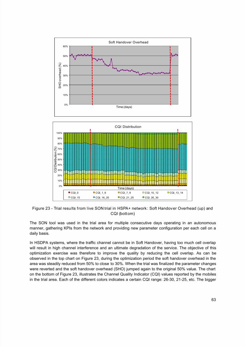
5/14/2018 Self Optimizing+Networks Benefits+of+SON+in+LTE July+2011 - slidepdf.com
http://slidepdf.com/reader/full/self-optimizingnetworks-benefitsofsoninlte-july2011
63
Figure 23 - Trial results from live SON trial in HSPA+ network: Soft Handover Overhead (up) and
CQI (bottom)
The SON tool was used in the trial area for multiple consecutive days operating in an autonomous
manner, gathering KPIs from the network and providing new parameter configuration per each cell on a
daily basis.
In HSDPA systems, where the traffic channel cannot be in Soft Handover, having too much cell overlapwill result in high channel interference and an ultimate degradation of the service. The objective of this
optimization exercise was therefore to improve the quality by reducing the cell overlap. As can be
observed in the top chart on Figure 23, during the optimization period the soft handover overhead in the
area was steadily reduced from 50% to close to 30%. When the trial was finalized the parameter changes
were reverted and the soft handover overhead (SHO) jumped again to the original 50% value. The chart
on the bottom of Figure 23, illustrates the Channel Quality Indicator (CQI) values reported by the mobiles
in the trial area. Each of the different colors indicates a certain CQI range: 26-30, 21-25, etc. The bigger
0%
10%
20%
30%
40%
50%
60%
S H O o v e r h e a d ( % )
Time (days)
Soft Handover Overhead
0%
10%
20%
30%
40%
50%
60%
70%
80%
90%
100%
C Q I D i s t r i b u t i o n ( % )
Time (days)
CQI Distribution
CQI_0 CQI_1_6 CQI_7_9 CQI_10_12 CQI_13_14
CQI_15 CQI_16_20 CQI_21_25 CQI_26_30

5/14/2018 Self Optimizing+Networks Benefits+of+SON+in+LTE July+2011 - slidepdf.com
http://slidepdf.com/reader/full/self-optimizingnetworks-benefitsofsoninlte-july2011
64
the CQI value, the better the quality and the higher the HSDPA throughput. As can be observed, the
number of high CQI values reported by the mobiles increased steadily when the SON solution was used,
returning to the original values when the parameter changes were reverted. The rest of the KPIs did not
change significantly, with the exception of data traffic, which increased steadily following the regular
growth pattern in the area. This simple exercise demonstrates that it is possible to optimize current 3G
networks making use of SON-like techniques.

5/14/2018 Self Optimizing+Networks Benefits+of+SON+in+LTE July+2011 - slidepdf.com
http://slidepdf.com/reader/full/self-optimizingnetworks-benefitsofsoninlte-july2011
65
6 SON CAPABILITIES IN HSPA+ TECHNOLOGY
While Self-Organizing Network management techniques are typically associated with the LTE technology,
this concept is not new to the industry and it can be applied to any network technology. In fact, early SON
techniques had been discussed, and even tried in 2G systems in the early 2000’s.
Wireless networks have been steadily increasing their level of automation, starting with early Automatic
Frequency Planning tools, which are today a “must have” tool for any GSM network, and more recently
continuing with the use of Automatic Cell Planning tools for the deployment and optimization of HSPA
networks. Furthermore, today many HSPA infrastructure vendors offer a set of automatic optimization
algorithms that are embedded in their OSS, which provide simplified network management such as
neighbor list optimization, planning of scrambling codes, optimization of power parameters, etc.
Additionally, there is a growing number of third-party companies that offer automatic optimization tools
that can connect to the operator’s OSS to extract the relevant performance management information and
provide an optimized set of parameters for the network.
The existing SON algorithms in HSPA+ are based on a centralized architecture and are therefore
somehow limited as compared to what LTE can provide. Furthermore, SON has not been standardized inHSPA+ and all available techniques are fully vendor dependent. On the other hand, much of the
performance management architecture is standardized in 3GPP, and some infrastructure vendors are
working towards embedding certain SON functionality in their NodeB, which will likely provide improved
performance and greater flexibility in the future.
The following are example SON functionalities available for HSPA+ networks today:
Antenna optimization (through Remote Electrical Tilts)
Sector Transmit power optimization (pilot and common control channels)
Neighbor list optimization
Soft Handover parameters optimization
HSPA Optimization
Energy savings
IRAT optimization
5/14/2018 Self Optimizing+Networks Benefits+of+SON+in+LTE July+2011 - slidepdf.com
http://slidepdf.com/reader/full/self-optimizingnetworks-benefitsofsoninlte-july2011
66
7 SUMMARY AND CONCLUSION
New and emerging classes of mobile devices are driving significant growth of wireless data usage.
Consequently, wireless service providers must now support a growing number of higher-bandwidth data
applications and services on their networks, while simultaneously driving down the delivery cost per bit.
This growth in wireless data demand is so rapid that it is also expected to increase Radio Access Networkcomplexity through addition of femtocells, picocells, as well as WiFi access points in order to drive
increases in coverage and capacity. These and other trends portend ever-increasing demands upon
service providers in the areas of network performance and operations. It has become increasingly clear
that traditional network management is inadequate for managing the growing data volume and network
complexity in an efficient manner. Whereas SON is an important tool for operators to improve network
management and efficiency, it does not replace the tremendous need for more spectrum for the wireless
industry to meet the growing mobile broadband data demands of customers.
Previous 4G Americas white papers and technical studies have shown that LTE – with its wideband,
highly spectrally efficient, low-latency and cost-effective technology – is ideally suited to serving these
new applications.12
A key component of the LTE advantage is SON, which is being standardized by
3GPP in Release 8, Release 9, Release 10 and beyond.13
LTE SON leverages network intelligence,automation and network management features in order to automate the configuration and optimization of
wireless networks, thereby lowering costs and improving network performance and flexibility.
This white paper has described the motivation for SON, and provided a description of the key SON
features contained in LTE Releases 8, 9 and 10. It builds on the descriptions of the SON features
described in the 3G Americas SON paper17
, by describing the newer LTE SON features in 3GPP Release
10 that further enhance the benefits of reduced OPEX and improved performance in operator networks.
These features address the self-optimization and self-healing capabilities of SON that will allow the
networks to operate at the lowest cost per bit while providing overall improved user performance. A key
goal of LTE SON standardization is the support for multi-vendor network environments, which has
resulted in the definition of standard messaging formats to convey information between entities that can
be used to implement a given SON algorithm. Examples of interactions between the various SON use
cases are described to illustrate the need for careful design of various algorithms and the setting
appropriate thresholds to ensure stable and robust operation. Each of the LTE Release 8, Release 9 and
Release 10 SON features clearly provide different and significant operator benefits in terms of
performance gains as well as operational benefits. Strong operator interest in LTE SON is evident from
the significant SON contributions coming from organizations such as the Next Generation Mobile
Networks (NGMN), and examples of the deployment of various SON use cases by 4G operators in their
respective networks. Results from SON trials in a live HSPA network demonstrate the benefits for
operators and provide further validation of the potential benefits of SON in LTE networks. Finally, the
scope of LTE SON functionality will clearly continue to expand and evolve with upcoming releases of the
LTE standard, thereby ensuring LTE’s continued success in tomorrow’s wireless marketplace.

5/14/2018 Self Optimizing+Networks Benefits+of+SON+in+LTE July+2011 - slidepdf.com
http://slidepdf.com/reader/full/self-optimizingnetworks-benefitsofsoninlte-july2011
67
LIST OF ACRONYMS
ANR Automatic Neighbor Relation
CCO Coverage and Capacity Optimization
CM Configuration Management
COC Cell Outage Compensation
CQI Channel Quality Indicator
CSG Closed Subscriber Group
DAS Distributed Antenna Systems
EMS Element Management System
eNB Enhanced Node Base station
E-UTRANEvolved UMTS Terrestrial Radio AccessNetwork
FM Fault Management
GCI Global Cell Identifier
HO Hand Over
HSPA High Speed Packet Access
ICIC Inter-Cell Interference Coordination
IRAT Inter-Radio Access Technology
IRP Integration Reference Point
KPI Key Performance Indicator
LTE Long Term Evolution
MDT Minimization of Drive Test
MLB Mobility Load Balancing
MRO Mobility Robustness Optimizations
NB Node Base station
NGMN Next Generation Mobile Networks
NM Network Management
OAM Operations Administration and Maintenance
OPEX Operational Expenditure
PCI Physical Cell Identifier
PM Performance Management
PRB Physical Resource Blocks
QCI QoS Class Identifier
QoE Quality of Experience
QoS Quality of Service
RACH Random Access Channel
RF Radio Frequency
RLF Radio Link Failure
RRC Radio Resource Connection
RRM Radio Resource Management
RSRP Reference Signal Received Power
RSRQ Reference Signal Received Quality
SDU Service Data Unit
SINR Signal to Interference and Noise Ratio
SON Self-Organizing Networks
TAC Tracking Area Code
TTT Time To Trigger
UE User Equipment

5/14/2018 Self Optimizing+Networks Benefits+of+SON+in+LTE July+2011 - slidepdf.com
http://slidepdf.com/reader/full/self-optimizingnetworks-benefitsofsoninlte-july2011
68
ACKNOWLEDGEMENTS
The mission of 4G Americas is to promote, facilitate and advocate for the deployment and adoption of the
3GPP family of technologies throughout the Americas. 4G Americas' Board of Governors members
include Alcatel-Lucent, América Móvil, AT&T, Cable & Wireless, CommScope, Ericsson, Gemalto, HP,
Huawei, Nokia Siemens Networks, Openwave, Powerwave, Qualcomm, Research In Motion (RIM),Rogers, Shaw Communications, T-Mobile USA and Telefónica.
4G Americas would like to recognize the significant project leadership and important contributions of
Kamakshi Sridhar of Alcatel-Lucent, as well as the representatives from other 4G Americas’ Board of
Governors companies who participated in the development of this white paper including Melanie Sater,
Pablo Tabia, Jeff Scott, Paul Stephens, and Peter Dahlqvist.

5/14/2018 Self Optimizing+Networks Benefits+of+SON+in+LTE July+2011 - slidepdf.com
http://slidepdf.com/reader/full/self-optimizingnetworks-benefitsofsoninlte-july2011
69
REFERENCES
13GPP TS 36.902, “Evolved Universal Terrestrial Radio Access Network (E-UTRAN); Self-Configuring
and Self-Optimizing Network (SON) Use Cases and Solutions.”
2 3GPP TR 32.531, “Telecommunication Management; Software Management (SWM); Concepts and
IRP Requirements.”
33GPP TS 32.511, “Telecommunication Management; Automatic Neighbor Relation (ANR)
management; Concepts and Requirements.”
43GPP TS 36.300, “Evolved Universal Terrestrial Radio Access Network (E-UTRAN); Overall
description stage 2.”
5NGMN white paper, “Next Generation Mobile Networks Beyond HSPA & EVDO”, Dec 2006.
6NGMN requirement document, “NGMN Recommendations on SON and OAM Requirements”, Dec
2008.
7 3GPP TR 32.531, “Telecommunication Management; Software Management (SWM); Concepts andIRP Requirements.”
83GPP TR 32.321, “Telecommunication Management; Test management Integration Reference Point
(IRP); Requirements.”
93GPP TS 32.511, “Telecommunication Management; Automatic Neighbor Relation (ANR)
Management; Concepts and Requirements.”
103GPP TS 32.690, “Telecommunication Management; Inventory Management (IM); Requirements.”
113GPP TS 32.511, “Telecommunication Management; Automatic Neighbor Relation (ANR)
Management; Concepts and Requirements.”
12
Rysavy Research for 3G Americas white paper, “HSPA to LTE-Advanced: 3GPP Broadband Evolutionto IMT-Advanced (4G)”, Sept 2009.
133G Americas white paper, “The Mobile Broadband Evolution: 3GPP Release 8 and Beyond - HSPA+,
SAE/LTE and LTE-Advanced,” Feb 2009.
14Garcia, L.G.U.; Pedersen, K.I.; Mogensen, P.E.; “Autonomous Component Carrier Selection for
Local Area Uncoordinated Deployment of LTE-Advanced” Vehicular Technology Conference Fall 2009
153GPP TS 32.500 “Telecommunication management; Self-Organizing Networks (SON); Concepts and
requirements”
16NGMN Top OPE recommendations, v1.0, September, 2010.
17
“Benefits of SON in LTE”, 3G Americas SON white paper, December, 2009.