selfx wiopt09 barth - semantic scholar · pdf fileall rightsreserved©alcatel-lucent 2009...
TRANSCRIPT

Self-X RAN
Autonomous Self Organizing Radio Access Networks
Bell Labs Stuttgart
Ulrich Barth
June 2009

All Rights Reserved © Alcatel-Lucent 2009 2
Self-X Business Perspective /
Bell Labs SON vision

All Rights Reserved © Alcatel-Lucent 2009 3
Self- organizing Radio Access Networks
Motivation
Current situation for radio access network management
� Deployment and maintenance become more and more complex and costextensive
� Trend to smaller cells, multi-band operation, heterogeneous mobile networks
� High manual intervention for configuration, capacity upgrade or in failure cases required
� High effort required for optimisation of system performance
� Deep system expertise required
� High effort necessary for measurement campaigns (drive tests)
� Different tools for planning, configuration, measurement/KPI acquisition and optimisation involved
increasing effort for network management and optimisation
���� new concepts for simplified network operation required

All Rights Reserved © Alcatel-Lucent 2009 4
Self-X Architecture
� “NEM less” network management
� Fully autonomous, distributed
RAN optimisation
� Self-x functions in UE and eNB
� measurements, UE location info
� alarms, status reports, KPIs
� distributed self-x algorithms
� Network management in NM OSS
focussed on
� network planning
� alarm and performance monitoring
� high level performance tuning
Vision of fully distributed self-management
eNB
LTE RAN
Network Management
eNB
eNB
self-x
NM OSS
Itf-N
X2-Itf
self-x
self-x
RAN self-optimization
���� performance monitoring
���� KPIs
���� alarms
���� high level network
performance tuning
OSS: Operation Support SystemNEM: Network Element Manager

All Rights Reserved © Alcatel-Lucent 2009 5
� RAN configuration use cases:
– Add/Remove cell incl. power saving cell
– Neighborhood relation configuration and optimisation for LTE
� RAN optimization use cases
– Cell coverage optimization
– Mobility robustness optimisation
– Interference optimisation for LTE
– Load Balancing
� QoS optimization use cases
– Scheduler operation optimisation for LTE
– MIMO mode selection optimisation for LTE
Self-Organizing Radio Access Network
deployment new site,
add new cell, capacity upgrade
self-configuration
performance optimisation
self-optimisation
tools for RAN planning,
configuration
and optimisation
conventional parameter
configuration
failure cases

All Rights Reserved © Alcatel-Lucent 2009 6
Self-Configuration of Radio parameters

All Rights Reserved © Alcatel-Lucent 2009 7
Self-configuration of eNB Radio Parameters:
Add Cell Use Case
Automatic Self-Configuration of Radio Parameters
� deployment/removal of cells/sites
� switching on/off of cells
Vision: fully autonomous plug’n play
� finding similar neighbors
� learning optimized configuration
from similar neighbor eNBs/cells
� calculation, adaptation and
negotiation of parameters
� distributed approach
� based on
� parameter classification
� parameter calculation
� similarity metrics
� configuration management
Parameter Retrieval
Config. Parameter Calculation Operational Phase
operatortemplates only for:
enablingnew features
preferences
initial defaults
parameter adaptation
negotiations with neighbours
outlier filter
self-optimisation
self-configuration
config-parameter classification
learning fromsimilar neighbours
neighbour selection: similarity metric
classificationown properties
and environment

All Rights Reserved © Alcatel-Lucent 2009 8
Self-configuration of eNB Radio Parameters:
Add Cell Use Case
What is and how to select a suitable neighbor?
� geographical proximity
� similarity of HW, cell properties (macro, micro, …; power class; …), environment
� parameter group wise retrieval from different eNBs (eNBs with different properties)
� similarity metrics:
based on
� vector representation of relevant parameters with weighting factors:
vector norm based identification of similarity (e.g. Euclidean distance)
Learning and storing good (optimized) configurations:
some optimized parameter sets depend e.g. on time and date, load
� for use in restart situations
� for distinguishing different optimized configurations (e.g. load dependent)
� recognition of parameter clustering
� cluster wise saving of configuration parameter sets
� cluster dependent reload of configuration data
l1
l2
mdmdm p
iiii BAWC )(, Θ•=C: distance measure, W: weights
A: current node, B: neighbor
Θ: generalized difference
All Rights Reserved © Alcatel-Lucent 2009 9
Automatic Neighbour Relation

All Rights Reserved © Alcatel-Lucent 2009 10
Automatic Neighbour Relation Function (ANR)
W-CDMA needs NRT for UE measurements
� UE are configured by NodeB which
cell to be measured (e.g. for HO)
� Centralized NRT planning required
No such restriction in LTE
� all UEs can measure the Physical Cell
ID (PCI) of all neighbours
� eNB can request the UE to measure
the Cell Global ID (CGI) related to
the PCI
� PCI/CGI is the key info needed in
NRT to map it further to the IP
address of eNB
� X2 Setup between the eNBs to enable
handover
UE
eNB
NeighboreNB
X2
NeighboreNB
SON ANRalgorithm
Neighbour Relationship Table
(NRT) per cell
Cell A
Phy CID 3
Cell Global ID 17
Cell B
Phy CID 5
Cell Global ID 19
Report Phy CID 5 Strong Signal
up to 15 eNBs

All Rights Reserved © Alcatel-Lucent 2009 11
Automatic Neighbour Relation Function (ANR)
Bell Labs decentralized proposal for ANR
� Start with empty NRT list
� Generation of NRT only based on UE measurements
� Update/fine tuning based on handover optimisation
� Detection and correction of PCI collision/based on ANR
Simulation Assumption for feasibility study
� Measure Convergence Time and HO failure in worst case scenario
� Only information from HO signalling is used
� No additional measurements used
� No signalling with neighbour cells
� Full radio simulation
12
34
5
612
34
5
612
34
5
612
34
5
6

All Rights Reserved © Alcatel-Lucent 2009 12
NRT Simulation (Hexagonal Grid layout 57 cells)
Inter Site Distance = 500 m95% Quantile of the NRT Completion Time
0100200300400500600700800900
10001100120013001400150016001700
0 0.5 1 1.5 2 2.5 3 3.5 4 4.5 5 5.5 6No. of UEs Per Cell
Tim
e [s
ec]
3 km/h 30 km/h 120 km/h
NRT list setup only based on UE measurement feasible
� Convergence time sufficiently short
� Worst case scenario simulated, as only UEs in handover process participate to
NRT
HO Drops Due to Incomplete NRT
0102030405060708090
100
0 0.5 1 1.5 2 2.5 3 3.5 4 4.5 5 5.5 6No. of UEs Per Cell
HO
Dro
p [
%]
3 km/h 30 km/h 120 km/h

All Rights Reserved © Alcatel-Lucent 2009 13
SON: Autonomous Coloring Algorithm for
Frequency assignment

All Rights Reserved © Alcatel-Lucent 2009 14
Autonomous Coloring Algorithm for Frequency assignment
P
f1 2 3 4 5 6 7
P
f1 2 3 4 5 6 7
Inter-Cell Interference Coordination
Self configuring and optimizing Network
Hand Over failure reduced by 5 fold
Increased the throughput up to 27%
Performance increase in call set up
Improve performance at cell edge
Self-organizing pattern assignment

All Rights Reserved © Alcatel-Lucent 2009 15
Inter-Cell Interference Coordination (ICIC) on terminal mobility
Pfull
P
f
Pfull
P
f1 2 3 4 5 6 7
1 2 3 4 5 6 7
a
b
d
e
c
Frequency Patterngreen cella. Mobile is scheduled to sub-band 3
with negligible interference from
orange cell
b. Mobile is scheduled to sub-band 2,
where orange cell radiates with
lowered power
c. Mobile is handovered
from green cell to orange cell
d. Mobile is scheduled to sub-band 4,
where green cell radiates with
lowered power
e. Mobile is scheduled to sub-band 3
with negligible interference from
cell 1
Frequency Patternorange cell
ab
c
de

All Rights Reserved © Alcatel-Lucent 2009 16
Autonomous Coloring Algorithm for Frequency assignment
Motivation
• Bell Labs ICIC approach requires frequency planning
But frequency planning is OPEX consuming
• � Provide a self-organizing solution
for cell (sub-)frequency (‘colour’) assignment
Challenges and � Bell Labs Solutions
• Known mathematical approaches are only centralized ...
� Fully distributed colouring algorithm inside each eNB
• ... and require much too much computation effort for real networks
� Efficient solution inside restricted areas by a novel successive algorithm
• Existing approaches are not adapted to the radio networks
� KPI for algorithm based on Interferences and n-tier neighbours
� Best suited colour solution found – also when a perfect one does not exist
• Decentralized systems can be susceptible to ‘instabilities’
� Advanced mechanisms to detect and resolve oscillation effects
� Advanced functionality to avoid “a moving wave of changes through the network”

All Rights Reserved © Alcatel-Lucent 2009 17
Major Steps of the Self Organizing + Self Optimizing SON Algorithm
Fast Initial Colouring:Each cell colours itself - if possible� ICIC immediately operational
Local Area Colour Optimization:Optimizing the colour assignment for several cells� Resolving sub-optimal neighbour colour assignments � Finding the optimal interference situation � Several advanced mechanisms to prevent instabilities� ...
Neighbour Relation Table (NRT) sufficiently filled� Scenario Creation / Update inside the eNB
Self Adaptation: Add/Drop Cell,NRT Change
Periodicoptimiza-tion by each cell
- Algorithm + signalling 3GPP compliant (i.e. LTE Rel.8) - Fully distributed algorithm, runs inside each eNB
All Rights Reserved © Alcatel-Lucent 2009 18
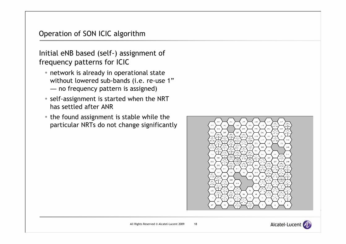
Operation of SON ICIC algorithm
Initial eNB based (self-) assignment of
frequency patterns for ICIC
� network is already in operational state
without lowered sub-bands (i.e. re-use 1”
― no frequency pattern is assigned)
� self-assignment is started when the NRT
has settled after ANR
� the found assignment is stable while the
particular NRTs do not change significantly

All Rights Reserved © Alcatel-Lucent 2009 19
Operation of SON ICIC algorithm
Modification of network deployment
� Addition of Omni-directional cell
� Initial color is chosen to the fewest
interference load (best neighbour)
� Subsequent optimization procedure finds a
solution by re-coloring the own cell and a
further (neighbour) cell

All Rights Reserved © Alcatel-Lucent 2009 20
Operation of SON ICIC algorithm
Modification of network deployment
� Replacement of Omni-directional cell with
tri-sectorized basestation
� Quick reaction of neighbors on changed
neighborhood in NRT

All Rights Reserved © Alcatel-Lucent 2009 21
Mobility Robustness (Handover Optimization)

All Rights Reserved © Alcatel-Lucent 2009 22
Configuration Parameters for Handover in LTE
LTE handover more sensitive compared to W-CDMA
� Configuration parameters
� Filtered RSRP values
� Handover Margin, i.e. hysteresis between source and target
� Time to trigger (TTT)
� Cell Individual Offset (CIO)
TTT (ms)
FilteredRSRP[dB]
Source CellTarget Cell
TimeHandoverCommand
Hyst(dB)
HandoverEvent A3
P(ms)
RLF threshold
Radio problemdetection
T1 (e.g. 500 ms) Radio link failure
TTT (ms)
FilteredRSRP[dB]
Source CellTarget Cell
TimeHandoverCommand
Hyst(dB)
HandoverEvent A3
P(ms)
RLF threshold
Radio problemdetection
T1 (e.g. 500 ms) Radio link failure

All Rights Reserved © Alcatel-Lucent 2009 23
Targets For Self-Optimization of Handovers (HO)
� To increase network performance by the minimization of Radio Link Failures
(RLF) and ping pong effects occurring due to inappropriate HO parameters
� To avoid manual update and setting of HO parameters after the initial
deployment
� To monitor neighbor specific HO problems
� Each cell monitors the HO problems occurring due to its own parameters or due to
specific neighbor’s parameters
� Every cell autonomously detects and resolves the HO problems by using
decentralized self-detection and optimization algorithms
� To avoid drive tests run specially for the detection of such problems

All Rights Reserved © Alcatel-Lucent 2009 24
Classification of HO Problems
RLF due to inappropriate HO decisions and HO parameter settings
� RLF before HO
� RLF before source cell receives UE measurement report for initiation of HO
� detection by source or neighbor cells
� RLF during HO
� RLF in source cell occurring during HO (HO command failure)
� detection by source or neighbor cells
� RLF just after HO
� RLF in target cell just after the successful HO
� detection by target cell
Short Stays
� Ping pong effect
� Rapid handovers between two neighbor cells
� Island effect
� Handover from Cell A to Cell C and successive rapid handover from cell C to Cell B instead of handover directly from Cell A to Cell B (avoid short stay in Cell C so called hot spot or island effect)

All Rights Reserved © Alcatel-Lucent 2009 25
Possible Handover Optimization
Avoiding high handover failure rates or too many short stays
� Detection of non-suitable neighbor relations by collecting and
analyzing handover statistics
� Optimization algorithms have to deal with rare and sporadic input values
� Avoid handovers to non-suitable neighbors
� Considering that in some cases only
specific locations at cell borders are
non-suitable

All Rights Reserved © Alcatel-Lucent 2009 26
Possible Handover Optimization
Optimization by modification of HO parameters
� Make sure handover problems are caused within the source cell
� Options for modification of HO parameters in source cell
� Handover Margin (HOM)
� Time to Trigger HO (TTT)
� Filter Coefficient and Cell Individual Offset (CIO)
� Simulation results
� HOM and Filter Coefficient can be fixed
� TTT must be selected depending
upon the UE speed
Normalized HO Rate Vs Residual BLER for ; TTT=0 to 200 ms; 20ms step
0
5
10
15
20
25
30
35
0 1 2 3 4 5 6 7 8 9 10
BLER [%]
No
rmal
ized
HO
Rat
e

All Rights Reserved © Alcatel-Lucent 2009 27
Coverage and Capacity Optimisation

All Rights Reserved © Alcatel-Lucent 2009 28
know how shiftfrom OAM expert
to manufactureroptimization algo design
Coverage Optimization for LTETargets
� detection and minimization of coverage & capacity problems
� load / UE density depending tilting
� cell outage compensation & power saving by switching cells off/on
Vision
� after planning and deployment of a new cell:
� fully automatic / autonomous optimization in eNB: antenna tilt, TxPower
� replacement of drive tests
� decentralized / distributed approach
New optimization process required:
cell global PM counters
drive tests, UE
call based traces
root cause analysispartly automated, expert driven
(planning) tool based re-planning
expert know how
parameter adaptation
ce
ntr
ali
ze
d:
off
lin
e,
too
l an
d e
xp
ert
base
d
UE measurementsUE location info
cell global PM counters
automatic measurement configuration, data evaluation
optimization algorithm
parameter adaptation
de
ce
ntra
lize
d:
co
ntin
uo
us,
op
timiz
atio
n a
lgo
rithm
base
d
alg
orith
m d
esig
n
⇒⇒⇒⇒
STATE OF THE ART SON TARGET

All Rights Reserved © Alcatel-Lucent 2009 29
Coverage Optimization for LTE
Challenges:
� complex optimization problem:
� collaborative (w.r.t cells and sites) and predictive optimization required
� interdependency with other self-x/SON optimization targets
(e.g. HO optimization, load balancing)
� spatially resolved detection based on UE measurements required:
� areas with insufficient coverage / low SINR / high interference
� areas with high traffic (hot zones)
� limitations/constraints regarding UE based measurements:
� accuracy, range and availability (radio link based and positioning data)
� statistical nature
� adaptation to network dynamics
� mid and long term changes in traffic load/distribution, interference,
neighbor relations

All Rights Reserved © Alcatel-Lucent 2009 30
Outage Compensation
Cell outage compensation by
� power variation
� no real compensation by power
reduction of neighbours
� power increase: drawback
large over provisioning required
� azimuth variation
� good compensation results (almost complete coverage)
but: normally not available in the field
� antenna tilting
� at least partial compensation expected

All Rights Reserved © Alcatel-Lucent 2009 31
Coverage Optimization for LTE
Impact of tilt:
CDF of Geometry reflects situation
in entire simulated area.
� Example with various tilt angles
9-21 degrees, 15 degrees provide
optimum coverage.
Simulation model:
� channel model: Okumura Hata,
shadow fading 10dB std dev.
� SINR: serving cell selection by strongest signal,
interference: sum of all remaining cells
� interference limited
� 500m inter site distance
coverageproblems
15°°°° 18°°°° 21°°°°12°°°°09°°°°

All Rights Reserved © Alcatel-Lucent 2009 32
Coverage Optimization for LTE
Optimisation goals:
� optimize CDF especially for low geometry values
� view: cell global
� - 3dB Problem of 3-sectorised base stations with re-use 1:
locations where 3 sectors have almost the same signal strength
� local problem, put in areas of very low user density
� discrete coverage hole:
� local geometry optimization problem with high relevance
� user density/ load:
� conditional probability distributions can be employed:
e.g. exclude locations w/o users, there is no need to provide coverage at all
� optimize geometry in high traffic zones

All Rights Reserved © Alcatel-Lucent 2009 33
Load Balancing

All Rights Reserved © Alcatel-Lucent 2009 34
Load Balancing
based on HO parameter modification:
� LTE intra frequency handover
� critical in re-use 1 schemes:
– no scrambling gain
– lower limit for usable SINR range
– especially critical: HO command
� potential for load balancing rather low
� LTE inter frequency HO
� no cell overlap SINR problem
– e.g. hierarchical cell structures
– to be considered: UE velocity vs. cell size, QoS requirements (e.g. GBR, NGBR)
� load balancing possible
� Inter system HO
� also no cell overlap SINR problem
– to be considered: service QoS requirements
� load balancing possible
�
�
�
with static ICIC, reuse 7/6
00,020,040,060,080,1
0,120,140,160,180,2
0 0,5 1 1,5 2 2,5 3 3,5 4 4,5 5
HO
Rat
e [1
/s]
TTTH=0.050 sec
TTTH=0.100 sec
TTTH=0.150 sec
without ICIC
00,020,040,060,08
0,10,120,140,160,18
0,2
0 0,5 1 1,5 2 2,5 3 3,5 4 4,5 5BLER [%]
HO
Rat
e [1
/s]
TTTH=0.050 sec
TTTH=0.100 sec
TTTH=0.150 sec
Residual BLER [%] (RLF)
Residual BLER [%] (RLF)
w/o ICIC
with ICIC

All Rights Reserved © Alcatel-Lucent 2009 35
Load Balancing
other approaches for intra frequency LTE:
� DL Power modification
� increased power in unloaded neighbour cells:
– requires PA over provisioning
– UL critical
� decreased power in overloaded cell:
– possible in interference limited (urban) scenarios
– degrading indoor coverage to be investigated
– risk of local coverage spots
���� ongoing investigation
� Interference coordination enabled load balancing:
IFCO as Enabler
� dynamic allocation of subbands for reduced power
� load reduction by dynamic IFCO based interference reduction
� seems to have higher potential, ongoing investigation
1 2 3 4 5 6 7
1 2 3 4 5 6 7

All Rights Reserved © Alcatel-Lucent 2009 36
www.alcatel-lucent.comwww.alcatel-lucent.com