selling and instilling matv - americanradiohistory.com · selling and instilling matv stlatreport...
TRANSCRIPT

91aTV -RADIO SERVICE CIRCULA
FEBRUARY 1969 if1 A HARBUTE FUBLIL'ATION
Sylvania Color lide Theater
Selling and Instilling MATV
stlatReport on Jerrold and Leader.

Color Power.EICO gives you the most professional
color power for your instrument dollar.000
INTRODUCING THE VALUE LEADER IN BATTERY -OPERATED PORTABLESOLID STATE COLOR GENERATORS-EICO 385!
Exclusive Features Compact "Tote -Easy" Design Computer -Type Circuitry Double Sided PC Board Construction Low Price
The versatile "go everywhere" EICO 385 solid state color generator, packaged in an exclusive compactportable/storage case, has been designed to furnish the service technician with five essential functions.The generated patterns are the standard offset carrier -type 10 color bars,precision dots, crosshatch, and an individual series of vertical andhorizontal lines.Advanced computer -type circuitry, coupled with three temperaturecompensated crystals, provides the drift -free stability inherent inthis instrument. A multipurpose color -coded gun killer with itsconvenient socket -adaptor assembly, (no more fumbling) storesin the case. Clips directly to TV antenna terminals (fast & sure!).The EICO 385 is powered by six long -life "C" cells or the ACadaptor accessory. The economical package containsall you need to enable you to do a fast yet reliable job.Easy -to -assemble Kit: $Wired: $109.95
EICO's complete Color TV Lab for the proPraised by the pros for laboratory precision at lowest cost
Model 369 Sweep/Marker Generator. For easiest, fastest visualalignment of color or b/w TV and FM RF and IF circuits.Five sweep ranges from 3-220 MHz. Four marker ranges from2-225 MHz. Crystal marker oscillator. Post injection ofmarkers. $99.95 Kit, $149.95 wired.
Model 435 Direct -Coupled Wideband Scope. Top-quality DC -4.5MHz scope with 3" flat -face. CRT Zener calibrator:Outperforms 5" scopes, facilitates on -location color TV andother servicing. $119.95 Kit, $169.95 wired.
New Model 235 Professional VTVM. Designed especially for solid-state servicing.Accurate to as little as 0.01 volts on its 1/2 -volt scale. RMS/p-p/DS/ohms in 7 overlapping
ranges. Big six-inch meter, 200 ua movement. $49.95 Kit, $69.95 wired.
NEW EICO 633 Portable All -Solid -State CRT Tester andRejuvenator. Rapidly tests andrejuvenates color as well asblack and white picture tubes.Line adjustment control, 12different filament voltages,individual voltages applied totwo of the grids, accurate meter- all insure precise measure-ments. Continuity and leakagechecked through transistorizedVOM, read directly on meter.$69.95 Kit, $99.95 wired.
NEW EICO 635 Deluxe All -Purpose Portable Tube Tester.Thoroughly professional,full -range modern versatility.Tests all standard tubes andeven the new decals, magnovals,7 -pin nuvistors, and popularTV picture tubes. "Take -it -anywhere" design expressed in amodern, rugged, scuff -proof,luggage case. Compact (4"H,121/2"W, 9"D) and lightweight,41/2 lbs. Quick, accurate,dependable and the price ismodest.$44.95 Kit, $69.95 wired.
NEW EICO PSI -1 Solid -State Signal Injector Probe.Perfect for on -the -spot signal tracing in the field.Pen -size, self -powered, self-contained signal generatorfrom 1,000 Hz with harmonics to 30 MHz. Idealfor trouble -shooting audio, IF & RF circuitry in anyelectronic equipment, transistorized or vacuumtube. Use it once - you'll never want to be without it!$5.95 Kit, $9.95 wired.
E/COQ
FREE 1969 CATALOGEICO Electronic Instrument Co., Inc.283 Malta Street, Brooklyn, N.Y. 11207 Send me FREE catalog describing the full EICOline of 200 best buys, and name of nearest dealer.
Name
Address
City
State Zip
. . . for more details circle 114 on postcard

ELECTRONICTECHNICIAN / DEALER
2x7=Mrs'COMPLETE MANUFACTURERS' CIRCUIT DIAGRAMSAND TECHNICAL INFORMATION FOR 6 NEW SETS
SCHEMATIC NO.
ADMIRAL 1205TV Chassis T3 K4 -1A, T3K4-1B
AIRLINE 1208TV Model GEN-11269A
MAGNAVOX 1206Color TV Chassis T938
SCHEMATIC NO.
PHILCO-FORD 1207Color TV Chassis19KT50 /508
SYLVANIA 1209TV Chassis B10-1,2
TRUETONE 1210TV Model 2DC3918, 19
If/ WI, INN roma I "NMI,N0III "MI Iffueffrip, 0,010 /10,5 r, NUN Mtn1050e1013 eIINT IIIIVII0120,
ffel,IN1001of
Ito SN-11-MOM
coSS,S
,pp_911015 10f-" r1N11(N0N5
LMINCTS 10
4/0114 100401
00her
01!
4002
3111Ni 14
r03, 701 1104
I II Ii
1
L_L _w 0.103
M103
r110/7
CMS 1,401111S1
1115' eNO
IN
V---4
.01
21
1.3043
LICIT
0055
VHF TUNER 94C363-2alt 101
SIC SIC 511,11 81.111 loll IMUD 011114311
3HA51/0
1,11111161
UHF TUNER 94C361-2
,510/ 011 --111T%; 114l
llMl
r "Itr ItTHr 14
63A59-1'sI
111001 mCMS.
1151 INIMAS
71-14
011111
'HT usI"11114
7 Ma 28
k
.///////413 511
Tt5' 57821-57- 00.
0u'
DS
Cl
"cos1i0 c
1/46
I. 53
I
0151
_4... 41
I11
---,,,,,,,,,,,,,,Salf LAIN If 1004RUN CI-IANGES
0 S 'or, al evemeuf NM
0507
OH OMB
IN
111711
cal l 41,10+4 Or
SirI10011
1p,
VdAr"1.COleNI
04/
1/25G57nl 012
0.3211011
f,o, SINll,
0/1 CAM
'01 --------/-
II
04
10
ELECTRONIC TECHNICIAN/DEALER is pub-lished monthly by Harbrace Publications,Inc., Harbrace Building, Duluth, Minnesota55802. a subsidiary of Harcourt, Brace &World, Inc. Subscription rates: One year $5,two years $8. three years $10, in the UnitedStates and Canada. Other countries: Oneyear $9, two years $14, three years $18.Single copies 60g. Second class postage paidat Dansville. New York and at additionalmailing offices. Copyright 1969 by HarbracePublications. Inc.POSTMASTER: Send Form 3579 to ELEC-TRONIC TECHNICIAN/DEALER, HarbraceBuilding. Duluth, Minnesota 55802.
1Os0
.1 501B,
1,41,1..11.1
:Er 1.2010I I,
1,2
_.1
NI
PRECISION WIRED SYSTEM 714E459.51/21713F11
50010 1(1*2010
00rrot
I/217BF11$14111 02111
1.10.0
'Si",.,ier
HA NN ICON
VOLUME551
1
SOSO
1200
T01111111
1/28BM1 I15111
530/I 1.1
8.302430147
Ala
SWAIN N11117- (NIPS mew Pa, WNW II PINI of i',e1 rile Sill I/ (WINS
0515199 11(9(3 ul UAW el/ Nan50155 IhelNelf
IC ISO /51(5 1f,51115 If le,/ loll,,III (II/III/ I ,,,e,011 15,5 MIN .4 .40
I wrote NUM MINN 40 Ner/.000
J
of 10(1r-31145 - Tuir -II moo
11119VIOL CI81 I
OK 2.0 0 0 0 .
_
r102111/N(
5303
551/ 0 of IN Meilaf tIN /(III, [NM'SKr SW M I" ial"Or5 150
moats INg
Of
110
cD/128
Cr,0
L300
-Pett$1124713557 NM/107 it
in
MO
V28BPAII2111IF
VSO1l /III130,41.410
1)05
1100Sti4
220 0.7
2t01
MC
2 Olt
11/1I7750 021
500
102/OH
1/214BL11*cc
IJ
5471
0302C
M41al
1INS411510 111
371, 83031'
.ItTUtN
'0?
cm,
mi101
1511111
Kb13
47
1/31111(1
4BL 11111
I 5300II -2
IV;
1205ADMIRALTV ChassisT3 K4 -1A,T3K4-1B
FEBRUARY 1969
1120,$011/1
Jo
MIS ear
61
11111 L.1,11TISOINI/1/0/
INNIIIef nor11 II II0.,
..S'"
;T1
A
S:7:33t:7,.,
ISIS
1 11\ 1001
sis Laos2.21 ILO gr.
1444717
Vs252 93116 SIP
10.
-Lsow
IT
MOT
01- 6 if tall420
MI 5511 "
a- r
In:103
-1101
0001 ":r01
I,VA
1011
/1
0111010
-7i 23Z9mow
Tr0,11
1St041 N`
CMI
13111.
211r
4/523Z91111
11111117.--,01121oC JL
051
-2.307 -71/1111040-0
UNITIES&
"16
-SNI1155010
11 rIONIC in
111LCo DJ IIN
20 Sr,
114111101
4701 1411
HEIGHT sms
102,ISO
IM
FOII
1401
VERT.HOLD
-III
(14111001110`
140j,5 ISM
VERT. UN
415
SI ICI 330'I. SSO.I1511/11N 1105
550,45-
050.12111140
L
93852-I.14
11511110M 500CR502
eLTe5402 11t,.11
175111 301407 23z15201 5403 5401
®O O® 4) CO0111
0430=7
1051
110
1531.1 91
93852-I 5 00501
simiikeime trC450/
0010.111
Sit M ow
6 8LT8NMI MIS( MI5402A 11/7
or
/Ir
MM./
I
j\A)-LNI010
1425201 MO
( V2 8 LT 8MI 1SC54.21
-fj art
_L
140 MO
5101 3101
C475
171.1111.
ls c. LILAC
!I
111
-IOf,
t1101 MN -wit(. 11;11..
,,,, _A...1.01131 *, CNN .- C503t
15x1Z.501 03.11131 1.01511 - ISO a a roni
fir
-r eft C000 MN in0012
072/9.22,0 IC 155!
NON"(WM. MO._ _
005
J4_01
110
rfir
71031":' 1141
,117
NN1201
1401111
1-r
INIrti'
51111 CO56401
'7e
1-41'2 :-- -
5404 I 101R11111
702NI ItC1
0A0I Cat "17 "4
11
I III
I
I1413 L3,1/138HK7
110101 011111115403*
(NIION VII
FOSS 14
/541 IN
14250406
Ira
364351 MC
WIDTHADJUST'anat.
PPM, e0011e10
1,IIICON I/(.5$0051 413101300
-o-1/01;
1107
oor NaarNOW Ws
HATA1171 N.
I
is on C421
51 14090 MI
09.
5330F11
oMD
10
IA
4*
COI
0
011
S fafolk
11503150(
20AF P4,20AFP4A
II INI S,110
l
143I
0:±
1..N NI WINN
fum (WIff III111101MUM WWINAP 1110,7 ',NUM OffINN MISS 001151
1 Mr mow," WI
Va 38H K7
0709
401
11.12154011
J1205 COPYRIGHT 1969 BY ELECTRONIC TECHNICIAN/DEALER HARBRACE BUILDING. DULUTH. MINNESOTA 55802

1206
#522SNAG
P N
R rt./0 00[0 CONTROL 110400-0C SOuRCE
MAGNAVOX
Color TV ChassisT938
FEBRUARY 1969'CA=
TIOS
ELECTRONIC Tr/TECHNICIAN DEALER
COMPLETE MANUFACTURERS' CIRCUIT DIAGRAMSAND TECHNICAL INFORMATION FOR 6 NEW SETS
CHASSIS LAYOUT
T201
-re e
T202 *C3araANT10.24
C105
1104 0 020SOUNDRACY
STK mayVINO NO
1.20841KTRAP
TIC0
POWERTaiwSTORINIR
vIRT 'CAL011C1)01/14.17
1.501SPIN WAVE COO.
0
NOWZONTY. Iv/OSCil/C NWS
F004IWCT
L
010266.41NV
ONO
1104 j
S 3040_10031
COWITOTT-
17111 01..OT
[620 1011W
ON CHROMA BOARD
0006701 11070i
120 COLD
1110 o
.-Irr
102
CWCuiT
0. MAW./.7(117-
50104ND CAN
000
005
C TGAGOELIAO
C103
00001 0412/0 .050
RCSCRAM SOU I...56110
L101815,02 jaw
811103
00.CIO
INV
230
"-ea.N122ruE
$1)wWIRE
03
. C105
450V
005MON
IS C20.9.
22.5PFOPT
7201WOO 0
a.p0T TRANS
330
2 ..110vvs ..140vv 270
0201OAR
T VI0E0 IF
35V 7.
7202AT v0E0
TRANS
x.700
3
10. 4 47000201 0202
ADJACENT
s-I 5%
SOvNO11,1
C202L201 ; .50 .0
472550 5%/0.0
C203..000
Cgc611203000 0101
2200
CEOS 0220000 WOO
3130 2
0204
3% 02074-. 6110
42200
TO
TO .5
7041400
TOW/44C
0)469203*
TO2700
DOTS 0.07
'am 4500 45430
11144.34
002000ew
.C11351661100
C.059
2111011,0
4501
840120.012
°;:=
°X.Z.
8161IWO38
COO*203I40- 3900
5140330
;gr..0161
V..°2",13Vo
aOr
61 13
8209ISO
C208000
501 NOT uSEDWAD
C 741, C 731
O 704,0731O 7). TM/4R,'11723.0724O 711,07{..
PITS7ITnt070100111.704
301.00TA0E-OFF
TRaid
:CPO
C70.
L.70 35- -1MO
LAST NOS DUDC712 77050794 T.O.7.2 C0702
L71111 TP701
TO 03
01010.0 SO
0702
n,
WWIGAINS
SOUND Wr -
4.14.0.0 TRANS
070413005 %
v701
134(.1)
SO'
0104 4701
FIN C,m OCI
,,Sor TA GC
01431201
C706
NIX*9
L702
0703GOO
11702 10%
SR
violGOTSA
SOUND 0C1000
ov
' 2000ov L703
rX2 . sVO0v
i
C701.O.
,.C-Ng;cc..CT.-.
r; 01 .021.__. ._--,0105 . 4,0.1 -
ROO '- - - -0. '0%
SY
at
4, 0709 NM5200 5200
I722 3101)72.
07112Tt4
03310;23
"725600
2604
0136300&GC
17;g 10RS
405
Lros62011.
V7OUWNW 072$
AOC 3300ir0
MOT07275600
2w
via120 C724 C729
2200 .50
8729220
IV 294/00
R7211100
0730 162(0
07030SON IA
SYNC SIP
TIV
0
2 00 -La
E45V202 INDT v0I0 4991113 TRANS
2110 VIDEO IF
.70v Ta
70.0 2
3.5v
3
02103 4
QM13 220 C231
S% .0.0 2 2* 25PF
NPOC210 COOS
C2 2 .1000.0$0I000. 1. ,
i02046020T 0226_ ..,_,
1441617cm 1.L202
I
400 0000 '.. a''''' 000
O702020 D 1 F... ........0.111
ACC -.TO 0005 80 No 0 TO 0120N3 0 2 -032010CE
--. TO °MONA SO FIN .. TO N SWITCH
C204F4000 R 0114
4*,300
SYNC
193015
C 5.0POO YOG
N5800 SIFT0510 VERT OSC.000
8513600
0308
NPO
NOS NOT 45(0WO 8570
657)
,004
IC5042200
054:-
3008 710 54004 ov
C52160 000NPO 43380--0-- 25 ,
CVO1050.
05253900
03292200 C524
520
039 004,400v
8542405%
351
35115
5v
az100
0222F"2200 1805%
33as
C2241.5*
83300' 23PC
L209
L2030E0DOT
020.SOUNO OCT
Cr.5%111.13
IAS 6000
TO40017
cD,STNCOUT
B
TO DITI. SO 1.10
8
1.214 Lvt04o DOT yEk.,..ZOT
02
NI CC 15
1
3007244v.0000210P TRANS I
1 42: C .C'2"1
021401)
x 'so' V.T.,
1121370
1.20410457(01
10 03
02.1143054300 C2.7
022100
TIRO. .C221
1 L207T WED DOT 1 11200
I C TI11212 I 120 I
56005%
42.7112005%
clgo.5%
NPO
02046SUN
SYNC AMP
01.20.
52)11
1.210 31
030Lzos
r.,SOUND
.NEJ
VIDEO IF BOARD
TO 200v
C520 VMS0519 0520 0082 110,771) 424 1. VERT OUTPUT
iC510680
IC5.5 + vo,...
0
61110 4700 .5230.1152, 8 3500
.0000
C332
Owcroon
T
;533.011.0/
83241500
F
727
V10411MAW '472°31''''......Cs%
oPNINO AMP A30 - 350011100 .
i 00
. 3 110 H
,-Tov$0
C000 O 10
2..p.L2011 La ago
C22?ISr
022{/5% .50
NO'S NOT uSED0560 TO 0569C560 TO C566
0342.40
C.332200
1011 750.YIN, 001.0
v50246707
0 DC CONT220
s0 9v
1153. ,a Jr
1000 05211 11.5040. Sp*
SPEC rad10%
TO v0E0 CONTROLCI60, 8080 FM 5
C3.6
C5.7.09T
v5029L.030:1 Si
6,07 aazoNOR1Z 09C2 0330
.C21.2 6
1111 tiJ:g5uct 500V
COO? 0030
0 iv S 310 850
01.900500
80.7:5%
8530270.*
c:12. C:2203"00550ISO
6534 05331500 17020 5%
85373302*
05381100
+0%
11.07 RIOS221, 50
NOWZONTAL NOE0
103850
5102
TO
70 03
NIANON12 OUTPUT
nAW/""3"K CIM 26°2 3043VIO4 ,, 00 NOT vioo
11.01011.101
100
i35r.
T 02 2.0 NV NECT
13V0141.0105(4
4,Rill130711
1-62
0112041
0.13*CO219
CI
0rvDEFLECTION BOARD
11 I 2'.8130.00
3PRONRIESS
00 RANI
0.0027
0105
FOCUS RECT. 8.02261E0
2w
.60 s
2100 PUL1ED
1100 O-
41potro
IC
98
11170.18 866244.30* VW
OW/9 N2200
014 27 4000
ICI IC/ Hr626.
o10V
PITS0NAM['NAM['E:
0, ,S
C.16 ^-t3640
3%
.064 L.04
L.02
F00111504
SOO)0400RP
I9.21000
T.03FOCUSTRANS
0
C1/04/00INV
81732 WC
5%
SP107
11174
162E45%
TO 2700
70 J003118 1 ICONvINGENCE 50 J80. F.N 71
P
1206 COPYRIGHT 1969 BY ELECTRONIC TECHNICIAN/DEALER HARBRACE BUILDING. DULUTH MINNESOTA 55802

c,,,47
F
G
H
11401AEGVOL
SAAUDIOAOSOuTPUT -is
7105MOO
0111.1.1171144$
20" 0714S 002.Or 1KV
Ti 2
117011
I
210111 IN
3125 ',WHIP--3300 G
CHROMA BOARD
2 .23/
/A017., 5,50A 11131
201048 1 MEG450V COLO.
kiLLERC.O5C
1511?5600 3500 TO TO .1.1
211107
SLO
0
mosK.
3.
14.01_4_(.7
TO .1409
3.TO 44100
117321011EG
070l4IIKCII/611105,
kIL IN kl)
"rc
C/251
704750
8733475
MM
2011440.
5:20
.7344
A
11/35
11730.00.
V70611SKE11.61406
2'11UNS7 510%224ov
Ts1::2;
°
*071173730*5%
. C730
029'20
5/30
270v11
v707A- 7 10,
IIANDAMsae, ?"'" Ar
17I1 la a J1 0v
4".11r,P4104 t".CT:4
47 )5 SV75 1411
0730 "0L3018 58
I 240v
C732 11742
047 330
4 4
73320
1,V LL
C1552705%
4;
X0/44 cvs.400 *1000LO
C 7055
1740536 li
R402500
COLOR...
1400
C764
og0
7.
M711112005%
C77504
L71311201.01
writ,07711 NAN2704 R -Y Sr
C76. 131570
01 I 50
L71547444
34
3 9
:RI 0 CI.
V7106MKIICIEMOD
11.042505
SRI
44400* 1T5
N/413300
11 442205
0737N
11.113 314C6
11133
25v Li1;-.)CONT
C466600
00WD
C7424
NO 4754112MEG
5%.5736A
NIG
743
R/54.2MO
4-s To AI
i
C744330
1017041 .541L709 111.1.ER
2011
I
1702.4956 TRANS
01463305%
70400
MEG410330 ,_,tect, R75. 330
C747
5% 000 5%N4300 45500 r
VI 1C111102411111755A PRASE44ED IX TECToft
di01151.0
MEG
0
-7441:C7411
DETECTOR
V NPO5 %4
410
8 ®LTIO
2011
71170
C74110'
AD
114, 721 DOT
C40472 M119Nut
VT0111AC70035 4IMM4510 REACTANCE 'IIINT
11763 .5U C/51500
...220
0444341111 7.730
57114214
.C159
070111 0703
4115 4 5
R745710
174166805%
V7056115111111 Hos
3.511111C
8 'os ,1115
0.0
Q2,r 335.cr
6v 2 C75827
4767
'=f3 A1,c
110-111--111-1,,4,.
A
Jr. a.m. .C755 0736- 15 4.7.2N110 REACTANCE 100
CONTROL .1.0
410
4 C/N53 45/64AA 474..
14.0
470
C737.74
131'5_ _
*7705800
44
70 53 T053
-110V
_A5772 0160470 220
+105 5%
TO VA
270v
1540
@WI2
,,, ,"6 f r
IT 712100
SIV *[+H11756
69 °'
C7,3047
R7111/ 20
VDU1111011
11-v AMP
100
LT141120 .799un 2704
5152066
.711113300
/0
V7IIC511011
11-7 *UP111008..
C770CP
V712 VfOG 0140
3 415 5
*790MEG
Tv-117922/0SW
T. CC
515027N
f)44
517.000
2* .75300.
C /511O
711.
.79s00.
C/7101
5,94
re
05
*a
-
4762127011
5160450
4;4:0-
C/3. 1
194050
TO 10.0100
ToCOLO. *LLE.---.
n434
4,03MOO
KL
0
Pa
C141VIOL 47
111111
ItauNT-RIO 2404.107o. .o.(2
Pv 245V r
5
544945%VG
co 2
01s v100
47.2
24102010
*1195
4030
-.450403SPARK 111424
sA. coo
5120 To..059
Wrev'p
00404
ROVE COO.!
Co20
1
MV
450
480
54.44
C1S1500.0.30v
TO 400
11,27IO
3.
...1.C4OTC
' 45005051,0
TE
..VENTCOLS
*033
412{
VERTCENTERING
04105
0171 7
-5
R
50031.11000Mosel
BOOSTED500111,200VSO,ACE
NO'S NOT u5E0C1{ 7.1411
64N-
4AC r3-2
'LK-wINT
5. wlwr.
.113
oT.Rao 30TOREG TILT
1807WONT sof
Distr 1.1L
L110.
c11.0.1 5.01 Iry.40
8857 41171
_ era_,0#14.5, ,__,"
ROME 110..SE-*-vie
MEN
01
CASE
ISISGO
111.02TILT
l3-3«10-]
05'3280 03*
=WI
/71,RED
AM 4 114-21
1111.2
ISO001 PEE44 AWL
8 G.. 2
!;41! Irv-
I4'11 t)"'")"") ".1°87,00.CASE
14-
`-"--:swc2esvocAlri
e l _ ;IF'4M., 2
02,,dm. CONS
LEFT GO(RA
0,5T TILT51104,20
5151-444
B13
I.') omr-. r ,«2 Al'
C.300
.0102.00140
0503053
0111)
Asos,20 ,
1.2,, DixOfE
nLT
c2lios
11907ISO
150Iw
CR1N*
C111104
40011150 r TEL -
01110
.
*maws, cans .
4
0511,.20
:571
AWL
450830
SLUEAYR
*504LEFTSIDESLUETILT
C1101
51505RION,NOE
SLUEAWOL
Tosoosno5000T,1200v 11
PIN XON DELL
SD
11425
33003.
111542300
ENT et'
TO 704050 44050
r-1110.1430.
L_3300
11,75400
15523100.
IAAO 123 .6°6,00,1 34140
5440'102117 5.445LNEAR.71 GAP
*824 411401006 10011
MAGNAVOX
Color TV Chassis T938
1350
512
4400
45451114/
54E65%
S,04sC40110.110NE
....._21/14 -03
S4,451.04E0
s.
HSRN
11V,0 -0100
ILA
.404E900
GREE0 N V R603 tDllevE 9000
01,12I.DAVE
c
5
.
J v -
116068400tr
184
51103 REOoW ROM-
/13,,0305 3014
11= of 4
my SC* 02*C6000
PLVT
5104Se5V10ESW470.
50.
$.71 m
SAL .MIN1751E6
*TO /0411
EINDEFLECTON SD
1
TO 71060
TO VIDEO ItPOO-.
541411
44000VERT
010111
11
I
IS
2
114,25141E0
G.E114SC. .01103000
101.3VAN5EDSCR
R.I.1000
MM1000 AA
5
116101000
.C104000
VIDEO CONTROL BOARD
0
uSAGE
TuNE.100 C.4.5114
000 IF
400500
CONT110. PANEL
OEFLECTON
600 0.330700 PRICN1A
800900
CONvEINNCE
AFC
V10111
2111V PE2t1OU22
1I REPICTURE
TUBE
TO WV2400
3910101003
301(5211.*C.1E5 .1541011 1189 10A1CriED10/545 2%
CW
3 MATCNED 04001 010111 AOC OE PC SOMADICOVIM MK I
s cApAcITANCE VALVES 04[87(11 MINmit 13 wc0S10108
CAP4CI1ANCE 041115 04 . AND LESS*( kloC1107115505
/ ALL rOLTAGES NESLAIO 0470 NOSIGNAL CAW, Tow IDENTIFIED50. AND ISO , 1SOuCE 001780E1 NE ASuntl) 4547. S4GraL .
PART3 MAY SE CONNECTED IN Carlin 211EC710/1OR ARAPEMED AS RE0045ED FO* 1401112 CENTERING.
10 COVEN 10 SE CLIPPED OUT ON SOME 011175
COPYRIGHT 1969 BY ELECTRONIC TECHNICIAN/DEALER HARBRACE BUILDING. DULUTH MINNESOTA 55802

1207PHILCO-FORD
Color TV Chassis19KT50/50B
FEBRUARY 1969
ELECTRONIC izilEnfiXi ACTECHNICIAN /
COMPLETE MANUFACTURERS CIRCUIT DIAGRAMSAND TECHNICAL INFORMATION FOR 6 NEW SETS
OSCILLOSCOPE WAVEFORM PATTERNS 19KT50/B CHASSIS
These waveforms were taken with the receiver AGC control adjusted for an approximate peak -to -peak output of two voltsat the video detector, using an air signal. Do not reset AGC control when using color bar generator. All monochrome voltagestaken with average air signal and all chroma voltages taken with a color bar generator connected to the antenna input ter-minals. The chroma peak -to -peak voltages were taken with the chroma control set for 0.5V peak -to -peak at Pin 2 of V40 andthe tint control set for proper color bars (approximately mid -range), all other controls set for normal viewing. The frequenciesshown are those of the waveforms not the sweep rate of the oscilloscope. All voltages taken with a wide band scope havinga SMHz bandwidth similar to B & K Model I i50.
416*2 VOLTS P/P 60 HZ Ai 2 VOLTS PIP, 15,750 Ai 65 VOLTS PP,WIMKK. CONTRAST) w H2 (MAX. CONTRAST) 41117 15,750 HZ
40 V. P/P, (MIN.o CON.) 15,750 HZ
/./130 VOLTS P'P,0 60 HZ
140 40, TS P15,750 HZ
nf 30 VOLTS P'P.
15.750 HZ
014 VOLTS P/P,60 H2
180 VOLTS P P,15,750 HZ
.5 VOLTS P 15 VOLTS P P.
15,750 HZ 15,750 HZ
6 VOLTS P,P,15,750 HZ
3.58 .1.:
JarAN 120 .OLTc, P P
W 15.750.7
ni 100 VOLTS P"R" 15,750.2
'IRA+'.'I .+..... Ie.
a 35 VOLTS pip,w 15,750 Hz
900 VOLTS P/P,W60142 (SPIKE)
ISO VOLTS P/P,60 HZ (SAWTOOTH)
oyi
liva,;w1O0.2 VOLTS P'P,
16,750 HZ
50 VOLTS P/P,15,750 HZ
08.5 VOLTS P/P,15,750 HZ
e 170 VOLTS P/P, W 15,750 H2 LOOSE
15,750 HI COUPLED
%of 20 VOLTS p/p,
15,750 HZ
SO VOLTS P P,47 15.750 HZ
O 8130.7V500LTHSZ P'P,
gi 310 VOLTS P/P. w 15,750 mz
90 VOLTS PIP,a.,(CHROMA)70 V. PIP, (SYNC)15,750 HZ
ak 50 VOLTS5,750 HZ
Jolt firAk 135 VOLTS P'P,W 15,750 H2 (MAX.
CONTRAST)
A. 2.8 VOLTS P/P,EP 15,750 NZ
TT
2.5 VOLTS P'P,O 15.750 HZ
in 45 VOLTS P/P, a 45 VOLTS P/P,T." 15,750 Hz 60 Hz
O 17 VOLTS P/P,15,750 HZ
!MIgh 12 VOLTS PIP,
3.58 MHZ
30 VOLTS P/P,ip (CHROIAA)
70 V. P!1,, (SYNC)15,750 HZ
1
111111111
11111
II Ii
* 17 VOLTS PW 3.58 MHZ
la 13 VOLTS P/P,15,750 142
r
O135 r. P P, (MAX.'.ON.) 15,750 HZ
O39 VOLTS P'1.1,60 HZ
VV\$71 5.5 VOLTS P/P, 50 VOLTS P P,- 15,750 HZ 15,750 HZ
2.5 VOLTS P'P, 60 VOLTS PIP,15,750 HZ 15,750 HZ
85 VOLTS P 'P,ICHROMA/70 V. P (SYNC'15.750 .7
* 140 VOLTS VP,w 3.58 MI12
28 VOLTS P/P,15,750 HZ
NOTES
1. ALL VOLTAGE MEASUREMENTS ARE TAKEN 11TH NO SIGNAL UNLESS INDICATED OTHERWISE
2. VOLTAGE READINGS ARE TAKEN WITH 4148 R I K MODEL 115 11TH ALL CONTROLS
SET FOR NORNAL OPERATION. ALL VOLTAGES ARE NOMINAL
3. RESISTANCES ARE MEASURED WITH YOKE AND CONVERGENCE PANEL DISCONNECTED.
4. 14.100115 4), , ETC INDICATE WAVE FORM TEST POINTS
vs,
2 VOLTS P/P,O ICHROMA1
5 V. P/P, (SYNC)15,750 HZ
O9 VOLTS P/P,3.58 MHZ
40
Nr"-
S640 VOLTS P/P,15,750 HZ
L20682UH
L397
IF,8
IF Me DETECTOR PANEL
r ---C3,-1TRAP
1.12
MI3L13
1C32 C33 42.75'L7
I3 T 6 -t
I 71.1 .T.Cr/ LI1111.14:1 I-
4- 147.2,MHz TRAPS
06
TP
pig
TVISA .1ST IF nv
C13
53.19
PSI1,58
219
_12330
5
23/C 30 Do,.001T
5./0
C1933-
C122.7
<330
c$3Tv1582190.1F
10 4.IV
11.54
5.59
R27470
CI7
3.0
RI9 CI8-1,544T 33C22
I.00
I(5
023
10014
R12820
C30A
IOOV
TpgC" R20A.0011 -A- ,5
0429'S IGO
2 A
R261.2K2
5%=
IM104Si. 82K,Le 1115
R9
k1!/:1 P11-47K
1E9 03
re E1SOI5
.0051
703vi8
LSO IC8
;14
R202ND. AGC R+4
5.; R4338 .new
1,5.K
C10- 6.R87K C2
VR2
R6005
C24-
,5JV
S AGCQ:2'.
5:--1.2'.1 -4. 2-75
2.2K'RIO iook
0.21220I1N600
C"
Ibobv,1600- eM4
I;UALGCSME6
M5
-t-
8224e. C215T AGC100 .1 SUSS
GREENPfULAGSE
AGC4 3_C
BLUE,6v
R1044.7K
VR205A7508VERTHOLD
-.14102V102
1/2 66118ASN IF
C106-47
02 2
ee1210111 126
R282705%
+10
B
C
R225
V203 S
6mu6TUNING INDICATOR
19K150ONLY
50V
60V
1
504
C10711
111
_t00; 22
M111
14109
I +160
RI2322K1W
C14382 -ID%
8136IOK
RI473308AV,
0101
624
r-
J-
11-IC105 I°"DOI
R116
Irr.c0C111722K
ill
L 01
SNO IF
01131lim781194.641
'5C1'
.00471.
4?
VR1028 +270/00K AGC 4671( t R103
3,,3K
100V
2
V1016056
?SKI DET OV
AN811722K
81188 2K
V103 2W
1/2 WAGSSYNC. +160SEP.
CII2poi I 8129
510K5%
111100.005
150 15K
130-6030-14
R1451M
1
I111iSr1? Jr;191;A0%
1KV,0v=]
C13252:1...
C136I.047100VC142
R146 120330K D1002 10% 01417
10%
R152ION
RI30 R133
I NI.I
680"I
tits-.006810%
400V
esv
10
V1041/2 6LU8VERT. OSC
1(C127100
I1508IC125
6130
CI25A
CII6H
.033600V10%
I(.047600V
itR144OOKIW5%
TS V 0103.1
271C1021
.0111'C122
.0082 10%IE
IKVCI23
100333KV
Ct011
H
3301
14,100
IF/127
4771W
C121D33600V
10%
J
R154.e2.2/4< CI17
813227K R155
5,6M
.01600V
VR1008 1W R131
t 11 -7VEIIT:".:TT.., .120K
luiVRIOOC R1S6 +270
M
3,4M 1,5MHEIGHT
RI41ISO
1104V105
6BL8 ,R126
6.29
HOP ; 15K T600V
1/2
REACT 2W
R125AV
VW'
CI47 200113990. 3
75V I
R15012011
DEFLECTION AND SOUND PANEL
L1031HON.FRED.
3
1C126
IL± C129
.0047125V
C130
1.0033I25V
+.+160
84V
16003
29 1
R161150K
V1051/2 6818
.0SC
R13839K5%
.8(1.45i
R14018K
MI16
=e---7VII2034mL...gg-
IK - a[HOP HOLD
V105 V104 V103 V10268L8 6LU8 61408 65148A
N
0
1207 COPYRIGHT 1969 BY ELECTRONIC TECHNICIAN/DEALER HARBRACE BUILDING. DULUTH. MINNESOTA 55802

A
B
C
04TV20
3RD. I1I3VRie22
231AAA
1MWC15t5 T
C21 1 ro,*°°1I 8.2K ir
CM' f,4115
E-VoTcrNro'
7255%.-9-1-120
C28 1416 C.410011Ke71.: 1 1(
1'8
C20 .005 I
C7145 16
I *
- - -_C35
i C16 KL._6,- 106I ILISKC341-(
R 33 I 33_J1 I D5 LO
I RFC' , ICA/
-4-C-gE1\---1-1,irR.374 R12 R33 CIN6°C/
I _L---iC6 1
-1
001 I 11.4 114 .0101 I I, .
10 I- , Jlk2...__.
CONNECTION FOR 19K150
750I SNO. REJ.
'I L2
1115L --
TON38
-IV
__q__. M 102A0110
1
.0C100847330vvi..
470K 12MR113 elm
1
1.-s6A- -.52-C2.203 :: R110.05 ,- i 1,5M50V
1IV
R109 RIOS1006 68K5%
$5 R10618K C109
15
15RFC
L5 D4
RFC
CONNECTIONmm19615011
J
L4
CooTAlAlafoc mid
8
,4.51,1142 C10,61 R212TRAP 8201
271
R138.2K -~-1-5% R2( ,
4,70 1 3
5%J560
R74 4R3vy
15K m9A
;;f. M3 I5%
,125 R2. M2C4
2201 T,(3.,%
PVIDEO 141
DRIVER .0056
14
*A11101
115jM1034
vI03In
6040811\1111ST. VI D.
R 204a
R101221A
RICO1.2M .
VRIO2C106
R149OISE INV 1.06
V102V2 6GH8A
NOISEin INV
Ri 354761W
C100.0068
V1042621 1/2 6L08
RT. OUT.
R1431.86
2505 ;V
4
124 8134
50µFR137 100V750SW
64100
vR 206IN
voLumE
$R1071.865%
81083.9K2W -
R112 A.111.211
3W
-sr 270
.35
1103
viA1024
COLORKILLER
R111
613 M12
+18
DL200
V10064054-- ALIO. OUT.
0
ON CONTROL BRACKET
3301
2
R1022702W
+27521
11100A
8211220
4,2K knErlit NOV
8124
_ vv. 3.17W R202
61116!47
M107A+175
Ni?:411 C.1119_
4031R159*. CI33100K .1.
0015 -
M124106134
Jtv 1000
Vol V1006CS6 6AOSA
394
R20191. SA470
V201 =6606
HOR. OUT,
6
5 2285 _I C104.0047
125
1011!
11E0
laR210 w220
J201
MI04
M106
14108
8128476m 111
M113
V.O.T.
4, Ir,
11.0T
R1601(.°K 600v
.001
VR1OOA750K
H. BIAS I MSAGC
PULSE
1112519
M6
M1051
BLU
_Lc21113
CONTRAST /1222
+160
+275
A.O.T.
A047.4'304
19
3111-
430K3W 5%R218
L204
4
10
0200
ALLTRANSISTOR BASINGS
82162.2 R2I7-w.- 16
81211K3W
20UFC208C
350V
VR2021.2KTINT
C11110144 PANEL14111-
M43
BAND PASS 11
1/2 6GH8.4 r CZO T v"52°500 ev37
1132600 KC.5,3
C.012214
00:30y L13603 So .1R362:49J, _COLO_Rfly
w.91
fC41
I
3.3
L_12
C524 inC56
÷-.04700V
Ms1-
C65 210V-411) 3 L411
L30 -112 II- --_tc69
1.15V
68 41A 1.001- .01
V37 -6v
.01 is°, =-I E
WR61 _.L
22K 21470
I R45
455 1/2 661184SK COLOR
R641;
31V KILLER1
I R3733m
C 3SA.001
2205V
1/2 66118*BURST I
AMP.
5 2205
I.6V C42 _L
TT
Y .0051RSO R39 1C40 = 2 R4082K 56K
1.01, 56K
- =
+27510x 136
9-3
167TP
n
I
-C361.001
R364 k0 v
----
V:ye " 63.215
0571100y.047
1165 _C63
I
863 540?C.> 1/2 6E103
MIS CHAO...A C70
/R74
-rev46
22K2705
- 22
,64 ,01
AMP
1820390 21.56
17 LT,-
21 E N371
1' 1
I 1330 IMI D39
04J
D34R43A
1.5KAAA
R4233K
4,76 56R43I C44-
-036
R42A
1141.5K
1330 IM I
1
330 1mI
C37 L -100
847C513.3I.5K
CT.O73
C48 _C52 *2 V
I610VPi
= C53IRe13
.01
150K
161
M55
2,6V
100
V3411/2 6G1111.6REACT C49
CONTROL.I
7.5
R56 146 C47m
270 15K5% 1W j_
cs, _t R96
4111
1305476
L49 R89 C7982 UM 1.56 .1
+18 IIF-' 100V5% 5%
V2023AW2
H V REC.
H.V.
C202130
8208
6KV
66M
FOCUS ADJ.
L202
Jvv-R203100K
R2074.7142W
-VERT'YOKE I
-
NOR. IYOKE.
FOCUS
+275.
C207.0613
600vI
L50471111
8871.5K
IV 2
5212GN7 235 reVIDEO I .1OUT. =100V
D37
14
= =
C5410
CS5 _lc
L42 Al
1
L
10
TIo _ 1
R548.261*
TAAA
059
1,01
R5220
V38
0 = V2 6Coli3A3.58 OSC.
1 2005 4
CR361= R53A
1
22 2 r-1453VC
22SO0 4711
IL39
'ARM;
t18K2W
1140
+160
275
VR204 R221500 100 -
BRIGHT
V42 V4126147 6E118
14101\C67_1_33 -r
1450 =
+270-R705.9K 5 L44
2451/6.7396OV 2 3
ISV39
1/2 6818'X' DE M00.
R66A56 2355
V411/2 6131.8
0E1600.
00 2
6
680
PHILCO-FORDColor TV Chassisl 9 KT50/50 B
524V39
1/2 6E118' R -T- AMP
C58.01
6618
R82
iw
C 7 7-
331
00 1 L46R69A 600
L43 56
ULM
R4915628
V40681.8
6115
R69 C68
R58
k2B7t3K
C72.01
R75im
R78S136
C71.01
R68 -C6,2 C76
VR36C
x
.014:4003 v1
8
I c58A
1m
504
R4420045/
2501C RTBIAS
R92
V401/2 6E11E1
AmP135 V
V411/2 6818 8-r" AmP
1505
C75
260V 1152 I
R804706
ROIR79 31563W C74
.1
200V
+275R83 C8015K .1
3W 2 V
R915306
1.001
R67
3906
.411.1V36 - IONA6GRRA HY. 25511V AT ZERO BEAM CURRENT
BLANKER CONT BRIGHT) +178
m401 24 61/ AT NORMAL CONT. BRIGHT.
MSS
R934
ii(1),15K
2.2K411,
V313661484
594
L HOReui .056 .1.11
.--11/2cov
1031E141T
- 6,1>
11
R181D1BOA 270
2W
C1116
T .331180
HOR.BLU
ea aI DI110C 018011me 14
R 180 M1183100 120VI L. ,40B.C184 R/03.062 VR186
200v 120 200VL. HOR.
R/G4
RI84100I W
C18502
C18 C183 HOR
,056 .056 J._t2 RED/
VERT.400V RED/GRN
CONVERGENCE
R183160IW
A223 NOT
REQUIRED WITH
11180 & TT190TUNERS
+160+ 2088 C2090
R223 10010-r33K aij_350v 350v
=
1105
185V V
1955
FOCUS .4
805
M-516
I I
F+2701
,- -I R157 F118061 3306
I755°25r-R16-3
-1116°"
1006 1006
I
5405
WzrI
VR101111.511
1RED
SCREEN
vR101C- -SCREEN
_C137 Si 39 ,T.001
1
1-
R206 R2132.30( 470iOW 2w
3W =
VHF 8+ SW C20842024 vHF 150LI F
TUNER) 3510V
-oh---i-
-17*190 VR 88 g VR12711
150 N 30V D1FF V DiFF
R/.114amP
VRA12.41./v. BLu v
AMP R/GTILTVRI85
120 Rie2100
RE 0/GRNAMP 01800I
TILT
8
VRI81v EILU
TILT
C2080100uF550v D203
VRI 01A1.5mCRN.
SCREEN
_C138
.1,001
+270
+275
11
RV200
0204
0205
C2074 D202'1 I
_C1104.0 1-
R214 +1606132W
+18C2098 +C2094
TEL/0111 600OF 50011F126/1 25V al 50V Cr
V
V201 V200 V2036606 6CG3 61.6/6
1 12 12 I 4 5
CR.T.DEGAUSSING
COIL
CIRCUITBREAKER
IL
5203 191150ONLY
C200P47400V
C2014.001
+270
BOTTOM VIEW
COPYRIGHT 1969 BY ELECTRONIC TECHNICIAN/DEALER HARBRACE BUILDING. DULUTH. MINNESOTA 55802

1208AIRLINE
TV ModelGEN-11269A
FEBRUARY 1969
TIHOIVHF ANT NT6-7U2
LC103
; 7PC112001
U9137152.7K
R7162.7K
105V87171.211
C104001
UT
103
ELECTRONIC 2J-TWELTACATSCHNICIAN /
R101 C10539011 .8. 5.
IC113.001 VIOI
3GK5VHF 87 MAPS UHF IF A11/P.
A.G.C. 140VK -UMT-76
COMPLETE MANUFACTURERS' CIRCUITAND TECHNICAL INFORMATION FOR 6
C10630P
VOLTAGE SYMBOL LEGEND
an I 3K V (row VOLTAGE)
IIII 350 V ( soosT I
gib 1E10 V
A 143 V 140V 135V
110V
70V
10-5V
.001
I LIX27
DC VOLTAGE MEASUREMENTS ARE I
AT NO SIGNAL. CONDITION.
8
V
7675312
13601680K
C601120P
7675HZ
136026130K
821182M
C211.22
CVIC I
C2
L2
L3
AIRLINESYMBOL DESCRIPTION PART NO.
C7013A.B,C- 200111/2000 !/50 11! @I8Ovelect TV32164R219 - 50011 pot AGCI9V1201 TV25234R314 SW701 -500K pot on -off vol w/switch TV2574
DIAGRAMS 18V020 UllNEW SETS R517 -1M pot vert hold I9V117) TV25237
R518 -1 M pot vert lin 19V1191 TV25238
UT6-2U2
RI6130K
15-750CV 2 or 11492/4
L7
LSilaDz.
GOO`01 Him C9 20P
CV3
R2 10K
01
C4L
C5CIOI 0.7P I1PT Q3P. 3
R4
0
ANT T13,1
UHFOUTPUT
C7l000P
1 14.7R6
CeR5
4664.7K 900P
L5 1.5K1
T201__7P01 2SC684 , 2SC387,
UHF OSC MPS6543 or TIS18
VHFC,07 L105
,p
3.0
81042 50 K
L104
vio26CG8A
T UN 1NG
CIIO001 TIO1 C118
22P
VHF MIK .OSC. 8 UHF IF AMP
C0:3117 I
13107K
0135V
I
K2 4,-*
3
1
7875HZ8603
0601
10V.,
V 70IA
10.1Y8
820222K
TP201
v301.4
I/2 6G H8ASOUND IF AMP.
C30147P
R302100K
0302 303.0047 27K
V201
4EHT1ST PIK IF AMP
-"V
R204
L201 82032IX
0022
7P 204
/JOV
0904 #2050012 2211 470
T301
V302
6HZ6SOUND DOT
R305560
V2024E J7
2141) P1X IF AMP.
TP202
R207180
82084/
J5V7
9
39V C2070022
C206 c2050022 seov
.1M1
erov3,34
2
R20970
R519 -1 M pot vert size I9V1191 TV25238R626 - 50 Kpot horiz hold 19V1211 TV25240
R718 - 20 K pot contrast 18V0071 TV2572R719 -250K pot bright 19V1181 TV25239
1201 coi147.25M11z trap 1211F4871 TV62248L301 -coil sound detector ITIF5441 TV62254L601 - coil horiz hold ITL231 TV61174T201 -xformer 1st nix IF & 50.25 MHz trap . TV62339
(TIE 3671
C303.01
787534,2
1
C3080
VOL UME
V303I2FX5
AUDIT OUTPUT
R308 R310112K ''''100
I W701i3
3Vp 1'2 10J Y8VIDEO AMP
R70297I7V 9.2"
/35 V
0 v
0022
T202 - )(former 2nd pix IFITIF3791 TV62340T203 -xformer pixdetectorITL991 TV622901301 -xformer sound IF 1TIF378 I1302 - xformer audio output 1711791 TIVV612121 '1115
T501 - xformer vert output 1811921 TV112161601 -xformerhoriz output 18FT6401 TV112241701 -xformersound IF 814.5MHz trapI2TIF4911
TTV6vi 212251821702 -xformer power choke 1912041M501 -capristor IPRC3021
w6TV3144457
5
yoke deflection assembly
Mg
.IT302 8323ri
gill 23111K22
7875HZ
CONTRAST
R7I6K24
1705
20K
,19
W705 R7063911
C31001
//Ow
8312 C309100
1702
12K
-/OV 8216 840190g 12K If/Y
2 I .9/00/'
R03
..IOSV
0
KEYED A.G.0 84028.2M
V60IA,
#21556K
561K 50t,
20V
8606
70K
C401 C02.01 470P
Mm
I
30V.,7405
ya75HZ $7K
v30113
1/2 6GH8ATPSYNC. SEP.
4
8
R2I7
2 2M
140322P
#404
(i) 330K
GOV...
7075142
v601
8F07HO#IZ. OSC.
c608
-NV
-1.C607820 68P
86071E1K
100V.-/ 1
30HZ
8501513K M501
C50,
v501
I 7JZ8C503 VERT. OSC.. VERT. OUTPUT0047
8503100K
.0022; i3KC504 R506
yr
840627K C502
am 920P
zer
C505
-II850 51.211
51611411519
IVI631213.K
R509150
6 7
'eV
C507
13507200
IM
R511356K
9
V -HOLD
41WV602
38HE 7 855615v8609330K 30g-140RI2 OUTPUT. DAMPER
V6018
R6013
TP601 62K
L6017V.-. I.0039 Hoc
TP602, /
R61182K
?sistaC6,0 86140047 68
861218K
mm, C609mn70P
711173HZ
1 FACTORY JUMPER
I °v.-.
H -HOLD,
R626Sok
145V
#613820K
8
/R63310
/V -SIZE
9V602AII /0o1/
CCII.047
R6161.211
#617
So
V60284
3.3K
c615240P
C6I4.0012.
L602
0613.069
R6I92213
KIE
KI
KI1
R5I0R508 ISOK
1.51,1r
II
7601
30HZ ,.1.C506
V5011301/
1(41
851100
1(12
V603I X2B
H.V. RECT.
MMR620
II RIC, .ca3.3
IIID
' ic) Rea I,,!p rcc6.80
[1111E..
OMJar
C65
13KV
608..-30HZ
76= --1)292Po bD K -
REO 171
ORAINGE 2
BLUE 173
00
10008
R5,322K
R7075 611
EARPHONEJ301
SP301
FOCUS
TO
GROUNI3045Vor350V180V. (2) (I) ( 3)
BRIGHTNESS I
C508.047
L_
II rh
01 4 5 4 3
3II
III C7I5
#5,48211
R710
.10,01140V C707
33K
138,8022
8711680
..K55146V
I2CNP4A
30142
- -37Pr 30HZ
27K
R7I327K
Winr T707 -Th457
<44'0rei
C 708A200
K5/3
IZ-UNIT-77
YELLOW 874III
I
I
BLACK 41(5 6 Ili
_
I P62210K
C6I7 R623.0047 270K
C6I2
FACTORY JUmPEN
7137HZ
350V
V701 V301
L703
.00227'7 C7'8
;C718 ;C0022 ;002270V v
8625 (T-14. 1)i013K 02 v601 rc"? viol uorKI3
7
V303 v302 V50i v602
C714
.0022; .0022;V202
5 4
V201
GOV.-. Ill
7F704
7131.022
5 4
719
;C720;C0022
.0022
I
6143
NTS - 7U2
V102
5 4
CI19
;001
C1113,.001imr 11
FUSEI.6A
OFF -ON /SV/701 C7
(PART OF R3111)
INTERLOCK
A.0 -LINE
OEN
1208 COPYRIGHT 1969 BY ELECTRONIC TECHNICIAN/DEALER HARBRACE BUILDING. DULUTH. MINNESOTA 55802

1209SYLVANIA
SYMBOL DESCRIPTION PART NO.
C324 -.001,, , 1.6kv 45.88215-17C432 - 20p1 5kv 43-11028-4C434 - 82pf 3kv N1500 43.95914-1C500 -3 section elect 41.27821-1C500 A -150-350v 41-27821.1C5006 -100.350v 41.27821-1C500 C - 5-350v 41-27821.1R118 -1M volume On/Ott 37.15287-3R224 -220K AGC 37-11632.1R248 - 7K -7w (-2 earl 35-92495.16R250 - 25K contrast 37-27837.1
320VPPNor,
14
17
65VPPVert.
3V PPVert.
3VPPVert.
2 )
15
580 VPPNor,
680V P P
R252 -1.5M bright 37.27837-2R318 - 5M vert lin 37.116321R320 -1.5M vert hold 37-27837-2R335 - VEIR 38-15275-17R340 -3 M height 37-11632.1R436 - 50K width 37.27868-1R500 -5015w 38.92898-18R502 - 18K 3w 35-92495-41R504 -1.7K 15w 36-92898-19R508 -411)15w 36.92898-48L100 - quad 57111602-1L202 -tilt adi 57-11811-11204 -47.25MHz trap 57-11837.1L206 -video detector 57.11852-1
0 250v P P
10E* 701......111418.
L302
0 140V
110 VPPVert.
O 60 VP PHo rig.
Ikl0
*NV(#112V1
35VPPHori x.
L500 - choke filter ..............L504 - choke ..........L508 -choke ........... .
T100 - sound xformer .........T102 - audio output xformer .....T200 - 1 st video IF xformer ......T204 - sound take off 4.58 MHz trapT300 -vett output xformer
L208 -filter 50-11634-1L212 - 22011 II peaking 50.15318-12L214 -820 II peaking 50-15318.19L400 - hoot hold ............ .50-27910-11.402 -filter 50-92043-3L404 - horiz lin ............. 50-15019-1
56-11651-650.27390-150-85983-257-11606-156-27824.157.11612-257.11604-156.27823-1
/ (7O
T100SOUND 1
rVIA
1/2 5K08 *NY 004 :1/2 6GH8A 3 (felVJSOUND IF AMP 2
-/V .I. C102i 8106(-411 1, 0047 I5K
20%7,14V ,i01411 +140vCVO R102 001 220(1
20%
R200 C200
3305%
0022
TO RII9
TO Cell
L200
v34EH7
1ST 9117E0IF AMP
L202TILT ADJ
02040022
czio
f?sfiG VIB1/2 5KDEI
1/2 6GH8AAGC AMP
R22322K20%
#I5.5V(0455VI
822633K
OEM#150V1#125V1
0/V10/31',-.
0022C222
00271s470(120%
8232 -C224
1462
00 001
2KV
TERM
Is
R2309 07CIVI 56K
,R5248
-1C214
000
8221220K20%
1'
War220KAGC
8504'SW
--)F-- _LINTERLOCK120v 608.
no, ce 05025n 300 oSOMFD SC502
LIC.L.0
302lo.
C50418K 33
,,,, ..,,, 2?/39- 8++.9,- _ri 3w
C510 C 508X K>01 FD 514FD047 1 1 001 anSC500I,50.14,:r 350V
3501'
R908350V
A +14090574 PO
176Y3 17./N6 100K6VS V7 1'2 V3
4E17V4
VII PI TUBEVOLTAGE KEY SYMBOLS = 41f1 8
12110 4(87L508
. +270V 5 4 1 12 4 5 I 12
MI +17XV
L5041
# WV(#13051
2
Cag'2(#90V) )1
#71'01411
1
00656PF
T2001ST 010E0 IF
4204 2210 82I647K
22(121' 0012 1,- 'OR
20% - 1IF
t If&
C20815
O L,
,12 MEG8206
I474 MEG4
823441on20%
4-140v
ELECTRONICTECHNICIAN / DEALER
1111111111161111111011111
0TO PIN I
OF SK500
)(--18116560K 0Cii8022
.2700®000
OUADRATURE
P
230 VP PVert.
2_f-',=/.4^1COMPLETE MANUFACTURERS' CIRCUIT DIAGRAMSAND TECHNICAL INFORMATION FOR 6 NEW SETS
T400 - horiz output xformer 50.27819-1SC20 - diodevideo detector 1 N295SC202 - -dc restorer diode D646201 -trans noise gate 26388 13-27050-1C8500 - circuit breaker 29-88908-5
tuner VHF .54-27848-1Yoke deflection 51.27822-1
1360 VP PVert.
TO PINOF SK500 028
1/2 12110Au010 OUTPUT
TO PINOF PL500
To 18114 6of PL500
VaIGI
10
,(1:151;)20%
^loT1
1/2vs*IOLY8
1/2 IOJT8VIDEO AMP
#141'(*,4V/ 7N.
R30582K
R241330(1
C23401
ii2 V(*WV/
5120220(1
C122
1C1240047
5122
.2709
40 VP PVert.
T102AUDIO OUTPUT
IIEL 11e UN
61/6V1
R242en
82487K7W
1204SND TAKEOFF4 5887 TRAP PP200
*246
44C0022TI
T3
r
90 V P PVert.
SYLVANIA
TVChassisB10-1,2
FEBRUARY 1969
12 82VPPVert.
11
L
£R3012K20%
rR300 A22« loco20% 101
330P,
.4270V
4100
©04
#1/01'
05000
L506
4 5
VI 05 065108 IOLYB SKEW
C5140022
5 4 4 5 5
0516
.1. 0022
TO PIH 3SK500
r -# 4 5V#5.5VI 2 cco22 I
'FFF,VA,
01400aloe
00471 680(1 0:112
044 EJ7
2N0 viDEOIF AMP
.122
0/60V01601/I
_LC221
9V PPHori
V2A1/212T1000.910 DE T
0
#1051' Rii4tfPC211 68K
5
I C.108470PF
#130V0,14RHO /
SB1/2
vIOLY8
V2 IOJT8 3SYNC SEP
PP300-40V1(-30113 2
11
LR3045303
C302Fax 001
)I -
C30301
01
2N388NOISE GATE
#110V
Is C23204
C3050033
tItt561E0.
8318MEG
VK
.v. )8310 cx.,150K pg. 1
VS.I/2 5108
1/2 60H8AVERT OSC
R340HEIGHT3 MEG
83,411.1E6
TO'le BOOST
1 R324I MEG
#601, 1
(,,,,,,,
9)C310
9
0223)5 ^- 741$
/18V1-119VI
8170v HOLD1584EG
R32560K
C3140022IK V R330
IX20%A
II
_L
8244108* .270v 214
R2451801
29
8328 *235v C318ISOK 1#23519 .068
-ISV 2
-T
LC312001 V?
1001(6VERT OUTPUT
C400OOP,
'R400470K
SC400?
ohs AFC.1144092
SC40R 402 vrli4I0K.
8401270K
C406 R4,0470PF 33K
TO -8-800ST
841682011
842247KIW
4/75Y0182V)
R30492K
BLU
WIZ')5312Sion
R353390K
C32400116KV
WRIT
SC202 D6462
ANSISRESTORER
EARP4ONE JACKR126390
0
R1213
MEG SPE44R CONECTION1-I VAMATION ONLY
C244 C250*PC .22 L216
220.11
8256456010
R25025KCONTRAST
C24447Pf
1-2R 66 R264I5K 1511
4100R251
20%
I.1E0012
TO TIEP0917
9,1105K
82593906
83443914EG.
TONTO
BOOST
300EV1
1133111 5 MEG
1/2v3KDEI
5412 MORI2 OSC36mEG
I /2
6GH8A1415
R410K 447PF
18
1400/E93
6
.4290114,1V7
23 ;
R411347K
Vs17J916
110RiZ OUTPUT
R436WiDT850K
C4 6j_ 843704 V
4.10R439
47---1-4P7-,1 -4:0vCI22001
(0/60V)
6428fga \<_J C420 I.20% _45, 2 330PF
6804 (-45V)
31V232V/C410 -L- C412
001 470PF
CowTIT. C404 +1755
82Pf
O
C419
CIII 5601347T
C 420
0033)I--,ssa 124i?
V1..
8424I2X
R43422KIW
7400HORIZ OUTPUT
II
1KV93HI/RECTIFIER
C43220P9SKV
TO C212
C402470PF
8406
27
8444'KR1,0
C43 I022
46
O
3,2 I
C434112PC3KV
4270V
844047K
01017AY3DAMPER
L404HORIZLIN
C4360336000
8" BOOST
400WIN (50
NW
- C327
82VPPHo,/
VII
20ZP4PICTURE TINE
17KV SPARS ARRESTOR
(PART OF CRT SK.)
'I470PF
11119
- C326
T.0047
.
ORG
- .27009262220K20%
YOKE1
L302 I
VERT;
OEFLEC,COLS
1
L300 I
L404I L013
104112 011PLEC.COILS
L
021C
T01.200
1209 COPYRIGHT 1969 BY ELECTRONIC TECHNICIAN/DEALER HARBRACE BUILDING, DULUTH. MINNESOTA 55802

1210TRUETONE
TV Model2DC39 18, 19
FEBRUARY 1969
SYMBOL DESCRIPTION
ELECTRONIC TT/v[5=TECHNICIAN / DEALER
COMPLETE MANUFACTURERS' CIRCUIT DIAGRAMSAND TECHNICAL INFORMATION FOR 6 NEW SETS
R208 -1 M volume control 8 on /offswitch S501 also inc. 6311 & 6313....75C126-2
R311 -25K contrast control Part of R208R313 - 100K brightcontrol Part of R208R411 -5M height control 75C101.16R412 -1 M thermistor 61C41-2R417 -1.2M vert hold control 75C100-8R421 - 500 K vert lin control 75C101-17R432 -27K 1/2w 5% 60E17-273R501 - 5.5 n fusible 61648-1C503 A - 250 µ f 165v elect 67030-12C503 B - 200 kz 1 150v elect 67030-12
C503 C -5411150v elect 67030.12TRUETONE 1201 A8 B - sound IF 8 phase shift coil lint C2121. .72001-4PART NO. L202 - quadcoil Uric C207 & R2051 72C132-82
L301 -47.25MHz trap 72C308-1L302 - IF input coil 72C308-1L303 -5.6mh RF coil 73953-243L304 - RF choke 7301-3L401 - horiz lock coil 94017-19L501 -filter choke 74018.601201 -audio output xformer 790124-1T301 -1st IF xformer 72008-2T302 -2nd IF xformer 72010-11303 -3rd IF 8 sound trap 72C185-7T401 -vert output xformer 79C123-1T402 - deflection yoke asses 700 0814-5T403 - horiz output 790117-5
VHF TUNER SARKES-TARZIAN *748-506110613 006C
1 11061
1
1
1
04101JI I
Imi05 1104
Itillilf
I 1103
±7'nirs-11I
L+4f4"1021 11
I
L1.,_4 jots n
0101
2 5
11051
VII if Silo11100(1 I P0111101
!An
L.
M1041
110
1.115-10110010 TO
111111A 1111111ALS
1
C104
T"
Is
1110
47
,110513 sVIIzscrpz,
14-1 11/26CG8ALIII
10( 1'1112mow ,010,11"
t0 IMO.-
C1051.3
L113 5
OlafCINNIC
:410i1 411
11021.21
allMOO
I IT -3 i000
140102
1110 C121 130
13
001 158
3GK5of IMPVIOL
1104
2201
VHF MISERw02.%
ITI
1104
1113
3100
109
''OS131
Cid
_1_0_100
(finON
VII I Wit 101115VIII OF 155/1110
473-112
rI
1/26CG8A I
1311 vv. IC
1104 CHO CIIIIll .-11-40-21-
Am 10 7 2
MI
:1101III
III 05C
Iv10213
2,1 F
1111
470
I
VHFCHANNELSLUG ADJ
SHIELD BRAID FROMCHASSIS CONNECTS
TO BRACKET
Top View of VHF -UHF Tuner Assembly,
Showing Connections, Alignment andTest Point Locations.
IF OUTPUT COAX UNDERSIDETO OF
HEATERS CHASSIS
BLACK 1,7747-,.3i
8+2 134V
sccBA
MIXER PLATE,PLATECOIL 1108
RileLor
--=-0411M
*M1S4 UHF IF OUTPUT JACK
61105 UHF COAX CABLE NOT SHOWN CONNECTED
1/3 148R11SOUND 11 IMP
V30213 !"6 514 III
0 2 0 1 A
ILO15%
COO47 /1202I011
61101 UHF IF INPUT JACK
UHFIFADJ.F
VHFANT.
UHFANT
RF AGC,TEST
POINT/USED WITHDIPOLE 61104
1/21713F11SOLID DU120.
4 510
120,13 Or
cool
C205r 120 .DIG, C201
-11103 CNN 1
L Aver
VNE TUNER
4 VIO2
6CG8A ER
I4V101
3GVAVHF RE
0311, AMP
--1 3
47-2UHF MILER
CR151
1-FISC0151
NE TUNER
DASHED LINES
NOICA1E
IOTTON VIEWS.
V30115T IF
2ND IF
V30319FBP4 - IN EIS 39180-06
20AFP4- II EIS 39191-06PICTURE
TUBE
8BM11
12
V302'
14BR11
VIDEO IMP&SOUND IF AMP
FUSIBLERESISTOR
93652-11.05,11,Diyu
17BF)1 CR501RECTIFIER
CR502CR502
soolvD200(11
SOUND OUTPUT
1N541VIDEO DOT
CR301SYNC SEP,
VERT.OSC I
VERT. OUTPUT
V401
23Z98LTB)V402HORIZ OSC
NORIZ PHASE DE T12
/*- V404- 1
N.V. IECT
IN SLEEVE
ON V CACE
TI
33677A
NOW OUTPUTDAMPER
DOTS AT rust- SOCKET LOCATION INDICATE KEYWAY OR INDEXING POSITION.
Tube Location and Heater StrirgIng Diagrom.
PWS 714C424-14
- r 3 r
.001111
111
1101151 -
MO/11
5%
1C201- 12200
Itl 12024 510
C2I0
4100
1011DOI
0044 0/00 /11111 sago, Sl
11.1.01IJJ
201ISO
1212
VOLUME
ISO
1/2 17BFIISOLID HINT
12018
120
L30213.0 Nt
L_
Is)
1/211III?FMI IV30tA
ulrT30114.110
111
Nen
gg'00301 lEAC C°10%
130111.251C11411
_$302 il302
0 lr 1;1y
130333
fra
1/28Bmilgg,'Fa
ft
1304220
1316 5
221
1305120
.210.
ICYNj500
10305
410)110%
li _car tIV' Ell `11 Itliium01.: 1/214BRI1
'
T It .-I( 1 I 1 01110 10
1145411 83024
MOO 0E1L
11 111
0302 CR301
10e
043'r
1 sot
1506700
L303 1304
CM/CI10%
03°1 IL
T11%i'
-1
1106
!21
11 IP
1111t
02011X00
012
10 1#,L I
011 00111
ji
iii07,1116
11(1112 -115111151
UHF TUNER SARKES-TARZIAN #474-515
II
10011
00.a
°-"--12%"Zli- )-l
013/11
I
611111110aw ,14
14,7 AVAIA7/.//' .%/ZAW //////,/
I.
101511121
I1153
C;501
IF ft ,ta3
1151221
100
T TT 051 1155
47-2umt Nati
CR151111200
TCVUHF OSC
1155 0151
1201
1
-1
1115
101,111
10133/Ott 111111
VHF MEN
riGKS 6C413AI viol 0302
0 0 0 0C 1 i000 C 31000
L
rNCIMRIVIE
V303
00
1C06 17(101
1400 1401
5-10( C 71810
'/314BR11ACC
V 302C
10
Or
1404
1/323Z9 H°9 IC401211
SYNC SEP
65
3301 -1.220.v401A 1101
III
02004 004
- 152. 220ii T143
z
.0,oir 0f 0r),
Is 40;17
r01111
110512110
13- 4
10117
330
10%
L306
1511
301
ft9030
M. 2011001
LA:.,.,560CP/
1201 C405 1411rano mop
.elf1_
/,,,,I
120 ini0%Iii
-CMSlSS
2r
I.01iM
1414 __C401sA
r,C40/ 11,1
.03110
I
1/223Z9rf 11 OSC
V4018
4, 11110%Or152,
1410
5001
31.51(0
1112NEC
IN/1415101
1411
II
64; CH1 HIS113,,10% 110101 sigI my
14,/ VIII5004
1/223Z9VIII RINI
v4010
VERT. HOLD VERT. LIN -1111101 013
1413R11V302
BITSV402
00 00
Off 1121 SIMI If141 mg /5 102411111. _
1200 AC 5011111 ellifta 11r.-Air.A,3FX=
1(111111111011110tS 00 MIAS NC PH Of 110r it OW S50146150210115 7,1
St1110/111115 11611
422101ensta11411 IV 11111111 II 111115/01 fail 5151(1
115/5 111 142115 /a 11,11 eaNC/101 2412(5 I12.121411 1112 Aar 1/11 5111/#1 If (111102 5
01(01.21115. 011155 111111/01 /1/10111II 101 10 A, .6 015011 II 110, if 241.00 5/154/.001 (0/1W1 1 11/(11114.01 III Nate PM rftsi
Morcott wow V111115/01 Of 111075/0, IWO515111 11 5115 10, Iliu1°( f
LINT
0301
00CRS 886111 -rum
1120-4r 120
'17E1F11 33017A 232911201 0403 0401
00 00 00C431
TOM111
93135111.1511',,
14 4 1151111/or
INST1-VU DIODE 93852-1CR502 SHAN IfC1i11(11 1501 11504
H.,IVID551 Ovi ION
CR5010507 1504 511vv. ,
.004;-.-71' C503l 9,0031 '.. CS03C 4.250011 - 2001F 5001III 1050 me - 1503 .. 1501
'/28LT8NocININSEDEI
V402A
Ill
_L-31 '
ipC65%
-2r
12r
1426
5601
C/15
10--)210.10%
-of
MOO
1421
5601
0415
51 2706
04111111
ilv10111
1/28LT81121
1°1 Off
1101 -11
MOVI OSCv402E1
11111?111
111110110
Sft moo rarriortaw
1/233GY7A110011 OUTPUT
v4031
111111
toImi,
Ho:12is 'C422 -÷-114
10020
9
1401 I560-
6100
111
14320 0/1:24fi/Ft
I
Ilfr
!.2:0
LOCK 1106
'31
'P54 Isa t 1001
HOT rt
$34211111,
i.15023 , AfOr
C425 5421 :4355% 1134 We 0/2111 04711
100 710°4 I 10
INOV
001111115411,
0(202WSI
3403r - -
1410
XVI eas2/1101"I
UO1
1437
la
00
1 L402 WWI CI///N OrL5111/rOO Or wail! protract 10111(151/( WW1
00 101 1111011 10 01511110421 C411
4 . T 11115011(55 51114111 115/
lzA 110 3 2" torooris proIII5% 5%
.A11
CAA 1/233GYTA I51, sir IN DUPED
11531114-16 040311
Or. 511 11
(1551110.16:1551
-T
C512 C513
20 5611
111111
;
CONTRAST
Z 1344 II
13151501
61201IMO
32A
51111 101011 11111111111141/ ,1,11
1111 411,
'4"
13:4
0
-4--
IBRIGHTNESSIOJI
550113 SPOT rAi 1ma
101
'-'
Sei1CoiliT1 1
I/0111 L
0111 0412
=II II44111 .02211
14112701
00201211
0
HIM700
1-47-011VIIIA_
0,111
1BC2 1402.1E1v404 I
Of 1.1004
CLOW 1""10
LAI
1111
19F6P4
2440-111153144 16
0101
511 0021111 C001/01
1210 OPY R 1 GHT 1969 BY ELECTRONIC TECHNICIAN/DEALER HARBRACE BUILDING. DULUTH MINNESOTA 55E102
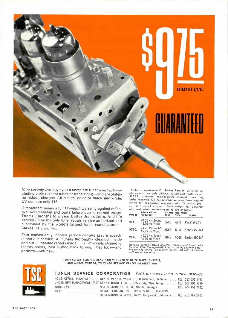
Nine -seventy-five buys you a complete tuner overhaul-in-cluding parts (except tubes or transistors)-and absolutelyno hidden charges. All makes, color or black and white.UV combos only $15.
Guaranteed means a full 12 -month warranty against defec-tive workmanship and parts failure due to normal usage.That's 9 months to a year better than others. And it'sbacked up by the only tuner repair service authorized andsupervised by the world's largest tuner manufacturer-Sarkes Tarzian, Inc.
Four conveniently located service centers assure speedyin -and -out service. All tuners thoroughly cleaned, insideand out ... needed repairs made ... all charnels aligned tofactory specs, then rushed back to you. They look-andperform-like new.
TSC
EFFECTIVE 8/1/61
tor MEED
"Prefer a replacement', Sarkes Tarzian universal re-placements are only $10.45, customized replacements$18.25. Universal replacements shipped same dayorder received. On customized, we must have originaltuners for comparison purposes, also TV make, chas-sis, and model number. Send orders for universaland customized replacements to Indianapolis."
Intermediate AF Amp Ose. MixerPart # Frequency Tube Tube Heater
MFT-141.25 mc Sound45.75 mc Video 6GK5 6L.18 Parallel 6.3V
MFT-241.25 mc Sound45.75 mc Video 3GK5 51_18 Series 450 MA
MFT-341.25 mc Sound45.75 mc Video 2GK5 5CG8 Series 600 MA
Genuine Sarkes Tarzian universal replacement tuners withMemory Fine Tuning-UHF Plug in for 82 -channel sets-Pre-set line tuning -13 -position detent-Hi gain-Lo noise-Universal mounting
FOR FASTEST SERVICE, SEND FAULTY TUNER WITH TV MAKE, CHASSIS,AND MODEL NUMBER, TO TUNER SERVICE CENTER NEAREST YOU
TUNER SERVICE CORPORATION FACTORY -SUPERVISED TUNER SERVICEHOME OFFICE, MIDWEST 817 N. PENNSYLVANIA ST., Indianapolis, Indiana TEL: 317-632-3493UNDER NEW MANAGEMENT, EAST 547-49 TONNELE AVE., Jersey City, New Jersey TEL: 201-792-3730SOUTH-EAST 938 GORDON ST., S. W. Atlanta, Georgia TEL: 404-758-2232WEST SARKES TARZIAN, Inc. TUNER SERVICE DIVISION
10654 MAGNOLIA BLVD., North Hollywood, California ...TEL: 213-769-2720
FEBRUARY 1969 19

Europium activated rare earthphosphor for redder reds,brighter greens, morebrilliant blues.
Replacement qualityyou can depend on...
Zenith engineeredand produced
Color Picture Tubes!
Zenith's aluminization processadds to color brightness.
3 -point mounting system for perfect alignmentof face plate, frame and shadow mask.Prevents shifting of color after tube warm-up.
Cinelens® picture glasstransmits more light. Andits dust -tight seal ends theneed to clean interiorglass surfaces.
Every Zenith replacement picture tube is made with the same care andengineering skill that go into the color TV picture tubes which Zenithproduces as original equipment.
Zenith's uncompromising quality standards-which include tubetesting at elevated line voltages for long periods-assure your customersof tubes with greater dependability and longer life.
Be sure. Order genuire Zenith picture tubes- for color or B&WTV-from your Zenith Distributor
EXCITING SJRPRISES FOR YOU-and Your Family! Fun for all!Get the details at your Zenith Distributor's Parts Department.
Why not sell the best
Tube funnel assembly.
Zenith precision 3 -gunassembly.
Zenith B&W replacementpicture tubes are madeonly from new parts andmaterials except for theglass envelope which,prior to reuse, Is inspectedand tested to the samehigh standard as a newenvelope. Zenith colorpicture tubes may containused material which, priorto reuse, is carefullyinspected, to meet Zenith'shigh quality standards.
The quality goes in before the name goes on

HUGH "SCOTTY-WALLACEPublisher
PAUL DORWEILEREditor
JOSEPH 1AUHARTechnical Editor
MARTIN PARLEYField Editor
DONNA BUTLERProduction Editor
KEN McSIIANEArt Editor
Bum CELINEAUCircidat' Manager
JOHN KESSLERManager, Reader Services
JUDY CREF:LYAdvertising Production
OFFICES
71 Vanderbilt Axe.New York, N.Y. 1(5)17PI (212) 686-2200
"Telex: 01-26286
43 East Ohio St.Chicago, Ill. 60611
Phone: (312) 467-0670Telex: 02-53549
Harbrace BuildingDuluth, Minn. 55802
Phone. (2181727-5511'Utley 029-4417
ELECTRONICTECHNICIAN / DEALERWORLDS LARGEST ELECTRONIC TRADE CI RCU;.ATI ON
FEBRUARY 1969 VOL. 89 No. 2
41 TEKLAB REPORT ON SYLVANIA'S COLOR SLIDE T. -MATERThis month's repert describes the circuits used in Sylvania'sexciting new color slide theater employing a small cathode raytube called the "flying spot scanner," used to transmit aphotographic slide to the TV screen
45 SELLING AND INSTALLING MATVFart seven of this series concludes the listing of manufacturersand products for MATV systems
49 DIGITAL TEST INSTRUMENTSA timely review of digital counters, voltmeters and multimeterswith specifications and prices includes many of the instrumentsavailable for service shop application
54 REPAIRING SOLID STATE RADIOSCommon troubles their cause and cure are outlined in thisinformative feature on tractor radios with practical applicationof test instruments.
57 EDUCATION AND CONTROLThis month's Dealer Fax profile explains the need for adequatecustomer training in what his color set can do and some of theaspects of maintaining an adequate parts supply
60 TESTLAB REPORT ON JERROLD AIM 718AND LEADER LCG 389Our Electronic Technician/Dealer lab technicians review thesetest instruments to explain the advantages and time savingcapabilities of these units
22 EDITOR'S MEMO 64 NEW PRODUCTSMARKETING REPRESENTATIVES24 LETTERS TO THE EDITOR 68 1968 ARTICLE INDEX
HUGH -SCOTTY- WALLACEChicago: (312) 467-0670 28 TECHNICAL DIGEST 71 NEWS OF THE INDUSTRYHAROLD N. LIEBER 50 DEALER FAX 72 CATALOGS & BULLETINS
New York: (212) 686-2200 58 DEALER SHOWCASE 74 ACVERTISERS' INDEXDONALD D. HOUSTON
Los Angeles: (213) 872-1572 62 COLORFAX 75 READER SERVICE CARDROBERT UPTON
Tokyo. JapanI.P.O.. BOX 5056
HARBRACE PUBLIC:'PIONS, INC.
J AMES 5111.1101.1,AND, JR.
DEUS \IVIIHAN
RICHARD MOELLERTruastirer
JOE 1%01.1sINCsemen VII,' 1'11,1(6411
!ABS FI..AI)AIABKSenior e PresidentHARRY RANI A1.1.1
Vii e PresidentBEN SIARSIIVice President
JAMES CIIERNAArt Director
1111.1.1AAI SA% AINSAO P1,1110t11111 Manager
AA ARREN BODINAd Proillactacm LiTtagri
COVERThe va ued use and application of test instruments in the service shop becomesincreasingly more important as specialized equ pments in consumer electronics andcommunication invade the realities of today's technology.
TEKFAX 16 PAGES OF THE LATEST SCHEMATICS Group 196AIRLINE: TV Model GEN-13469AGENERAL ELECTRIC: TV Chassis P-1MOTOROLA: TV Chassis TS11 SeriesPHILCO-FORD: Color TV Chassis 19QT85RRCA VICTOR: TV Chassis KCS171 Series
ELECTRONIC TECHNICIAN/DEALER is published monthly by Harbrace Publications, Inc., Harbrace Building,Duluth, Minnesota 55802, a subsidiary of Harcourt, Brace & World, Inc. Subscription rates: One year $5,two years $8, three years $10, in the United States and Canada. Other countries: One year $9, two years$14, three years $18. Single copies 75C. Second class postage paid at Dansville, New York and at addi-tional maiuing offices. Copyright 1969 by Harbrace Publications, Inc.
POSTMASTER: Send Form 3579 to ELECTRONIC TECHNICIAN/DEALER, Harbrace Building, DJI..ith, Min-nesota 55802.
FEBRUARY 1969.4E... for more details circle 149 on postcard
21

SPRA-KLEENL
Catalog No. 8666.6Suggested NetCatalog No. 8666-16Suggested Net
In2Ljigr
II.N.1,11.10/ d.
Eliminates noise due to dust, dirt and corrosion onall electrical contacts. No need to dismantle chassis-SPRA-KLEEN penetrates those hard -to -reach placesquickly and efficiently-cleans and lubricates in oneoperation, saves time and effort.
Always insist onyou'll get more for your money, every time!
GC
GC ELECTRONICS DIVISION OF HYDROMETALS, INC.MAIN PLANT: ROCKFORD, ILL. U.S.A.
Giant New FREE Catalog! ...Only GC gives you everything in elec-tronics... has for almost 40 years. Write for your copy today!
IGCELECTRONICS
has everything
in ONENIOALS
EDITOR'S MEMO
Watts a Volt?It's happened! The International
Committee of Weights and Measuresmet in France last October and ap-proved a new temperature scale whichgoes much lower than it previously did.Other changes made by the committeewere in the reference base of the voltand in the values of gravity (the gyro -magnetic ratio of the proton and theacceleration due to gravity at Potsdam).
In addition to these changes, majordecisions were made with regard tointernational cooperation in radio fre-quency measurements, accurate timedissemination apd standard referencematerials.
The National Bureau of Standardshopes to be able to calibrate thermome-ters on the new scale after it is pub-lished in April 1969.
The International Bureau of Weightsand Measures was authorized to de-crease our goofl old volt by 11 partsper million. They say that this willbring the "practical" volt closer tothe theoretically defined volt which iscalculated from basic mechanical unitsof length, mass and time. The changebecame effective on Jan. 1 of this yearand national laboratories all over theworld will be busy making changes soeveryone ends up in agreement withthe International Bureau.
The change in the U.S. legal volt, asfixed by a group of "standard" cells atNBS (the National Bureau of Stand-ards), will be 8.4 parts per million ratherthan 11 because the NBS volt and theBI PM volt have drifted apart by2.6 parts per million since the lastadjustment.
So our old volt is changing and itlooks like further activity is plannedfor comparisons of measurements ofradio frequency quantities such aspower and attenuation.
for more details circle 116 on postcard
22 ELECTRONIC TECHNICIAN DEALER
At last!A practicalway
to provideservicing training
right in your own shop.
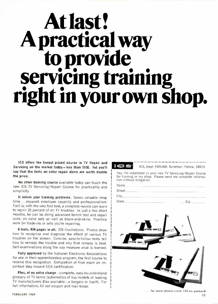
ICS offers the lowest priced course in TV Repair andServicing on the market today-less than $100. Yet you'llsay that the texts on color repair alone are worth doublethe price.
No other training course available today can touch thenew ICS TV Servicing/Repair Course for practicality andsimplicity.
It solves your training problems. Saves valuable shoptime ... expands employee capacity and professionalism.Fact is, with the very first text, a complete novice can learnto repair 20 percent of all TV troubles. In just a few shortmonths, he can be doing advanced bench test and repairwork, on color sets as well as black -and -white. Practicework on trade-ins or sets you're repairing.
6 texts, 936 pages in all. 329 illustrations. Photos showhow to recognize and diagnose the effect of various TVtroubles on the screen. Concise, easy -to -follow texts tellhow to remedy the trouble and why that remedy is best.Self-examinations along the way measure what is learned.
Fully approved by the National Electronic Associationsfor use in their apprenticeship program; the first course toreceive this recognition. Completion of final exam an im-portant step toward NEA certification.
Plus, at no extra charge-complete, easy -to -understandglossary of TV terms (schematics of top models of leadingTV manufacturers also available-a bargain in itself). Forfull information, fill out coupon and mail today.
I ICS, Dept. K85188, Scranton, Penna. 18515
Yes, I'm interested in your new TV Servicing/Repair Coursefor training in my shop. Please send me complete informa-tioi without obligation.
Name
Street
City_State Zip
FEBRUARY 1969. . . for more details circle 124 on postcard
23

FASTCOMPLETE SERVICE
N ALL MAKESOF TV TUNERS
Maxim
(WE SHIP C.O.D.)
YOU PAY SHIPPING
$9.95
BlacWhite
or Colo
VHF orUHF
UV Combo's $16.50
Price includes all labor anexcept Tubes, Diodes & Transis-tors. If combo tuner needs onlyone unit repaired, disassembleand ship only defective unit.Otherwise there will be a chargefor a combo tuner.Ship tuners to us complete withTubes, Tube Shields, Tuner Coverand all parts (including) anybroken parts. State chassis,model number and complaint.
)Sc
All tuners are serviced by FAC-TORY TRAINED TECHNICIANSwith years of experience in thisspecialized field. All tuners areALIGNED TO MANUFACTURERSSPECIFICATION on crystal con-trolled equipment and air checkedon monitor before shipping toassure that tuner is operatingproperly.
GEM CITY TUNERREPAIR SERVICE
Box 6D Dabel Station
2631 Mardon Drive
Dayton, Ohio 45420
. for more details circle 117 on postcard
24
LETTERS
TO THE EDITOR
Japanese JunkWhile there may be some merit in
your finger -shaking editorial of October1968, the Yankee ingenuity and know-how that has brought us Hi Fi fromHong Kong, transistorized tape fromTaiwan and junk from Japan may alsomake "lion tamers in Northern Siberia"big money.
One thing that many of us havelearned from our servicing experienceis that change and innovations don'tnecessarily represent technologicaladvances-in other words, a cheapermousetrap isn't necessarily a betterone! The technicians, like the doctorsyou mentioned, are specializing andstaying on top of those advances thatpay off. We'll go along with anythingthe engineers and sales people want todesign and sell-if we can make a liv-ing wage at it and are not singled outas the ultimate goats by manufacturerand consumer alike for not being ableto make their space age bargains per-form as claimed by the seller and asexpected by the buyer.
Servicing procedure and techniquescome from experience. And if properlyapplied, they will help any technicianto efficiently locate and replace defec-tive parts in any electronic equipment.Unfortunately, the same cannot alwaysbe said about design procedures andtechniques!
If and when the level of our rapidlyadvancing industry gets 100 percentwith the "$6.75 super, solid state,space age, giant 21/2 in. speaker con-cept," you may live to see "lion tamersin Northern Siberia."
H. NEUMANWaldport, Ore.
Prime ToolPlease accept this letter as an ex-
pression of sincere appreciation andgratitude for printing my letter request-ing a Harmon-Kardon CPR -2 preampli-fier. It resulted in my locating oneof these units from a supplier in LosAngeles.
1 have been trying every possiblesource for this unit with no results,and until my letter appeared in yourmagazine, the results were nil. ELEC-TRONIC TECHNICIAN/DEALER has al-ways been one of my primary toolsand it shall continue to be.
KEITH CROCKETTSt. Joseph, Mo.
Our thanks to H. Neuman, KeithCrockett and others for their commentsand letters...Ed.
NEW
"tray biros"most versatile of all
nuioriver setsHandy "Tray Bien" sets lie flat or sit up an abench, hang securely on a wall, pack neatly in atdol caddy.
Lightweight, durable, molded plastic traysfedture fold -away stands, wall mounting holes,and a snap lock arrangement that holds toolsfirmly, yet permits easy removal.
Professional quality Xcelite nutdrivers havecolor coded, shockproof, breakproof, plastic (UL)handles; precision fit, case-hardened sockets.
Holds toolssecurely
No. 127TB "Tray Bien" set -7 solid shaft nut -drivers (3/16" thru 3/8" hex openings)
No. 137TB "Tray Bien" set -5 solid shaft nut -drivers (3/16" thru 3/8" hex openings) and 2hollow shaft nutdrivers (1/2" and 9/16" hexopenings)
No. 147TB "Tray Bien" set -7 hollow shaft nut -drivers (1/4" thru 1/2" hex openings)
WRITE FOR BULLETIN N666
XCELITE. INC., 14 Bank St., Orchard Park, N. Y. 14127
In Canada contact Charles W. Pointon, Ltd.
. for more details circle 148 on postcard
ELECTRONIC TECHNICIAN/DEALER

The Seven -Year itch.Remember when we introducedyou to our Television Analyst(model 1076)? That was overseven years ago, and she'sstill the only diagnostic tool ofher kind. But now there's anew number. A smart looking,professional model (1077) withdesigns on your heart.
Sure your old model still works.Why not? It was made by B&K.
But, of course, she can't do someof the groovy things the new modelcan do. Like testing TV sets withUHF. And testing transistorized TVsets with complete safety bymatching the impedances oftransistorized circuitry.
The 1077 analyzes every stagein color and black -and -whiteTV sets-without external scopesor wave -form interpretation. And
she does it with a standard testpattern (or special pattern slidetransparencies for color circuitry),all of which we supply. She does ,tall: from antenna input terminalsto the grid of the picture tube,using the unique B&K s gnalsubstitution technique.
When you do get together withour Television Analyst, she'lleliminate those hours you wastedon tough dogs, intermittents andgeneral TV troubleshooting.(Hours for which you often don'tcharge the customer.)
Here are some more of hergood points: VHF and all UHF RFchannels; IF; video; sync; chroma;
audio; bias supply; AGC keyingpulse; and signals for completeanalyzing of sweep circuitry,including flyback yoke test,and horizontal and verticalthiving signals.
Got the itch? Contact yourdistributo' for complete detailson how tc start a new life witha Television Analyst.Or write for Bulletin 1077.
Model 1077. Net $379.95
A Division of CYNASCAN CORPORATION1601 W. Belle Plaine Chicago Illinois 60613
Where electronic innovation is a way of life.
for more details circle 105 on postcardFEBRUARY 1969 25

600 BUCKS WORTH OF TVHERE'S A GUY
WHO NEEDS BELDENANTENNA LEAD-IN
CABLE!
SETAND ANTENNA ANDSTILL A LOUSY PICTURE !
. . .
-------.
.......... .
Color or UHF set perfect? Antenna perfect? Then obviouslythere's a missing link. Check that antenna lead-in cable.Old, worn-out, weather-beaten cable, or the ordinary flatribbon kind designed for black and white VHF, causes morefuzzy, distorted pictures than you can count. It's youropportunity to upgrade these customers to a cable matchedto their particular signal reception situations. One ofBelden's Big Four-the link to perfect reception.
FOR CONGESTED AREAS ...
8290 SHIELDEDPERMOHM
LOE0 PEEN1OHNi FOR 42 CHANNEL
ll l MOH
In congested, in -city areas, L,tray electrical interference and noise areat their worst. For perfect, all -82 channel reception-color or B/W-replace old cable with Belden's 8290 Shielded Permohm. Its aluminumBeldfoiF shielding prevents pickup of ghost signals and electrical noiseby the lead-in. Weather-proof and water -proof. You can tape it right tothe mast. Or install it underground, in conduits-even in rain gutters.
Om. North Nom.AWG & 0. D. Velocity of Capacitance
(Stranding) Color (inch) Propagation (mmf/ft.)22 (1 x 30) Brown .305 69.8% 1.8
x.515
Copperweld. 2 conductors, orange polyethylene insulation and webbetween conductors, cellular polyethylene oval insulation, Beldfoilshield, stranded tinned drain wire, polyethylene jacket.
agirs:nuationper 100'
MC db5/ 1.785 2.1
177 3.2213 3.5473 5.4671 6.6887 7.7
StandPackage
Lengths in ft.50', 75', 100' coilshave terminalsattached.Available in counterdispenser.250'. 500' spool.
26 ELECTRONIC TECHNICIAN/DEALER

FOR FRINGE AREAS...BELDEN 8285 - PIRMOHA4
112113
l'IPAItitil/H11:'
Antenna cable in uncongested or fringe areas picks up littleelectrical interference. But does get a lot of weathering, whichdegrades an already weak signal. These customers needencapsulated cable. Belden 8285 Permohm. Its special poly- ----?..<;*- --"-------..._iethylene jacket protects the energy field, regardless of weather n.....-----
conditions. It delivers the strongest signal of any unshieldedtwin lead under adverse conditions. Requires no matching -transformers and connectors. For all 82 channels, color or B/W. v -
-e' '--\T_-
i
ff
..1.J ,IA4
rtigalIITIMIrt X-,/-'- i
Nom. Nom.Velocity of Ca acitance
Propagati:._22 (7 x 30) Brown .255
x,1 .t"I 5.3 100 1.4,
300 2.850'. 75', 100' coilshave terminals
Copperweld, 2 conductorsweb between conductors,
I
1
.468parallel, orange polyethylene insulationcellular polyethylene oval jacket.
I
I
and500 3.8700 4.8900 5.6
attached.Available in counterdispenser.250' 500' coils and1 0 0 6 ' spool.
FOR LOCAL BLACK AND WHITE...-..
827.1 I. E1/1411 IAINE-
.
i
A "... e",- - .4., .j.,.
Cracked, corroded,loses signal strength;
weathered cable,prevents any
fullTV
of dirt and moisture,set from delivering a
..-.- .-ir-, .. -...._
s'\
quality picture.to Belden 8275all possible moisturenated. Abrasionlong service life.
Upgrade B/W VHFCelluline. Performarce
between conductors-resistant and weatherAnd, it requires no
and
end
local UHF customersis improved because
has been elimi--resistant for a long,
sealing.
AWG &(Stranding)
Nom.0. D.
Col nch)
Nom.Velocity of
PropagationCapacitan(mmf/ft.)
Wont. Attenuationper 100'
mc 1 db
stannaraPackagengths in ft.
20 (7 x 28)
Bare copperweld;gas filled unicellular
Brown .300x
.400
2 conductors parallel,polyethylene core.
80%
polyethylene jacket
.1 (:
with inert
100 1.05200 1.64300 2.12400 2.5500 2.98700 3.62900 4.3
50', 75', 100' coilsin counter dispenser.250', 500', 1000'spools.
DUOFOIL j FOR MATV AND
112211CATV...
11111111111; COAX_
(...- ........
Got an apartment or townhouse complex in your area? Motels Q. ._!....)..L1...._.
or hotels? Or is CATV coming? Use Belden's new 75 ohmcoaxial cable -8228 Duofoil. Shielding is 100%-sweep tested IMPA (2
,)100%. Spiral wrapped drain wires provide long flex life. Small Stit c
diameter saves space in conduit installations. Use Duofoil
.i _J
\ ...__J._:., -
I 4 - -,,
i
for all coaxial color and B/W VHF, UHF and CATV applicat.ons.
Nom. Nom.Velocity of Capacitance
tion (mmf/ft.)Nom. Attenuation Standard
per 100' Packagemc 1....... db Lengths in ft.
p18 Black .242 78%
Solid, Bare: /. i 50
100200300400500600700800900
1.52.13.13.84.55.05.56.06.56.9
100', 5i qi, I 00) rspoof..
,I See your local Belden distributor for fulldetails or to order. For a free copy of therecent reprint article, "Electronic Cable,write: Belden Corporation, P.O. Box 5070-A,Chicago, Illinois 60680.
BELDEN el-.NCOklp
FEBRUARY 1969
far more details circle 109 on postcard
27

Dyna-ProbeNew King -Size,Hi -Voltage Tester With2% Accuracy At 25,000 Volts!
Professionalcase included
B &K is proud to introduce Dyna-Probe, the new, longer, safer length,hi -voltage tester designed to givemore accurate voltage readings.Servicemen carry Dyna- Probe toin -home jobs-adjust high voltagewith greater accuracy, thus relievingcustomer fear of color TV X-rayradiation. Detachable meter is easyto read in "hard -to -reach" areas.Meter, on auto -tilt stand, direct -reads 0 to 30,000 volts. Dyna-Probe-another engineering break-through from B &K.Model HV-30, $24.95 user net
B&K Division of Dynascan Corporation1001 W. Belle Plaine Avenue I Chicago. Illinois 60813
Where Electronic Innovation Is A Way Of Life
. . . for more details circle 106 on postcard
LETTERS
TO THE EDITOR
Vectorscope ErrorI would like to say "Sock It To 'Em"
regarding your replies in Letters to theEditor, November 1968.
I want to be among the many whopraise your magazine from cover tocover. I am a subscriber and will con-tinue to be as long as the material inyour magazine is of the quality ithas been.
Your article on vectorscope serv-icing in November 1968 has an erroron page 44. It states in reference to aZenith TV "a 6v source should be ap-plied to point C1, the ACC." It shouldread "test point Ql" as C 1 is the out-put of the video detector.
FRANK KOLDE, JR.Chesterfield, Ind.
Business Anyone?May we take this opportunity to
thank you for the excellent trade maga-zine you make available. More thanonce a problem has been sitting on ourbenches when your magazine arrivedand solved the problem for us. Thearticles are timely and well written.
We would like to provide an oppor-tunity to one of your readers whomight want to lease or buy a going tele-vision service business established forfive years in the fastest growing countyin the United States, Orange County,California.
The area serviced is in the mediumhigh to high income group. There is nolimitation as to potential growth. Thebusiness is situated in the central partof the county with access to the com-plete freeway system nearly at the door.
The shop is equipped with all thelatest equipment and currently run-ning two trucks for service and antennainstallations.
We would like to have inquiries fromany of your readers that might liketo make a change. We would providefinancial information to interestedprincipals. We will require financialinformation on anyone interested. Allinquiries will be treated in confidence.
MARVIN LEHRERBayview Electronics Service20056 Santa Ana Ave.Santa Ana, Calif.
Readers' AidI wonder if one of your readers can
tell me where I can get the tube layoutfor a German radio. It is a PhillipsCapella #673. The tubes of this set
were removed by a child and I have noway of knowing what's what. I alsoam looking for a wiring diagram for aNavy receiver (long wave); Type Cnd64155, radio receiver serial 1934; Aunit of model Rak-2 radio equipmentmanufactured for the Navy Dept. Bu-reau of Ships by Andrea Radio Corp.,contractor RCA, Camden, N.J. Con-tract NX sr 38089. 1 sure would liketo get these pieces of informationif possible.
STANLEY MAGALSKIStan's ElectricKensington, Ks.
I have a DeVry 5 in. oscilloscope forsale. It needs some repairs but it's agood scope. I am moving and want tosell it before I leave. Maybe one ofyour readers would be interested.
HARRY SCHUHH&H TV Radio135-09 83rd Ave.Kew Grdns, L.I., N.Y. 11435
I have some Rider's TV Manuals,Volume 3 to 8, just like new and somewere never used. I would like to sellthem for $1.50 each, if one of youreaders could use them. I would prefera local serviceman so he can pickthem up.
AL CRISPO159-30-90 St.Howard Beach, N.Y. 11414
Perhaps an ELECTRONIC TECHNI-CIAN/DEALER reader can help me finda schematic (wiring diagram) fora DOSS-Pioneer 250 HorizontalQuantalyst.
I would appreciate any help fromyour readers.
My best to all and many thanks forall the fine articles.
MAURICE DUBREUIL VE28U1740 Notre -DameLavaltrie, Que.Canada
I have been receiving your magazinefor some time and find it very interest-ing and helpful. I have a problem and Iwas wondering if you could help me.
Three or four years ago I bought anautomatic tube tester (floor model) tobe used in a drugstore in town. Recent-ly I wrote to the company that made itfor a new setup chart and it is no longerin business. I paid about $350 for it andI hate to see it become obsolete. Pos-sibly one of your readers can give mesome information to update it. Thetester is a Model No. 36-800 and soldby G. C. Electronics Co., 400 S. Wy-man St., Rockford, Ill. I would appreci-ate any assistance.
ALBERT CATALDOCataldo TV511 Main St.Wellsville, Ohio 43968
28 ELECTRONIC TECHNICIAN/DEALER

I'm gladyou askedthat question...
Who offers the most profit in tuner service?
Would you believe PRECISION TUNER
SERVICE does?
If you're one of our thousands of long-
time customers, you've already had it
proven to you DAY AFTER DAY.
But, if you're not, you'll want to know
how we got all those happy customers-(steady, satisfied customers, that is)
.1ot.0...\41040
They tested us and learned:
IN PRECISION TUNER SERVICE is dependable . . . quality work . . nocomplaints . . just conscientious service!
PRECISION TUNER SERVICE uses only ORIGINAL PARTS. . . no
home-made or make -do inferior merchandise! (This is why we chargeextra for major parts)! You get your tuner back in ORIGINALEQUIPMENT condition.
PRECISION TUNER SERVICE is fastest! Speedy 8 -hour serviceevery time. No phone calls. No wondering.
PRECISION TUNER SERVICE is more profitable! The cost is less .. .
up to $5.50 less than other tuner service! Major parts, tubes, tran-sistors charged at net price. UV Combos -$14.95
%AM' AND NOW FOR EVEN FASTER SERVICE-A BRANCH PLANT IN TEXAS AND CALIFORNIA, TOO!
4(. ?
414 -
Why don't you test us and find out?Don't make it easy on us . . .
don't give us n break !
you get...Fast 8 hr. Service!
$8 95
For finer, faster PRECISION TUNER SERVICE,send faulty tuner with tubes, shields and allbroken parts to:
1 Yr. Guarantee
PRECISION TUNER SERVICE
one of the OLDEST and LARGEST tuner service companies in the country
WEST: 2325 WALDORFTURLOCK, CALIF. 95380TEL. 209, 632-2928
HOME OFFICE: 1210 S. WALNUTBLOOMINGTON, IND. 47401TEL. 812, 339-9653
SOUTH: 332 W. TYLERLONGVIEW, TEX. 75601TEL. 214, 753-4334
.. for more details circle 140 on postcardFEBRUARY 1969 29

TECHNICAL DIGEST
DELCO RADIOLoose Ferrite Sleeves in AM Tuners
When there are complaints of radio volume going upand down, as well as static on bumpy roads, the problemmay be that one of the ferrite sleeves in radio tuner is loose.When a sleeve comes loose, it slides back and forth detun-ing the radio and causing the volume to vary. Occasionally,it may slide forward enough to short cut coil leads causingstatic. When the radio is standing face up and the backbumped gently against the bench, the loose sleeve will movedown and be visible between the tuber housing and coil board.
TUNINGSLUG
COIL aCOIL FORM
CIRCUIT SOLDERBOARD LUG
INSULATING INSIDE FERRITE TUNERSLEEVE SLEEVE HOUSING
COILBOARD
The correction is to replace the tuner assembly with anew one. The tuner cannot be repaired because the coilboard is permanently staked to the tuner housing.
MOTOROLAAlternate Method of 4.5MHz Trap Alignment in Solid -State
B/W Receivers
In some chassis the visual MHz trap alignment may becritical because of its sharp attenuation characteristics.
The following method of alignment may be used byemploying a VTVM and a 3.58MHz demodulator. This isthe same demodulator used in the 3.58MHz trap alignment
V 9E0 1.1,1r PF DI UDE
O
on TS914, 918 and 921 tube type color chassis. If a demodu-lator is not available, one should be constructed as shown.Alignment Procedure: ( I ) Connect the VTVM and demodu-lator. (2) Tune receiver to snow -free picture. Fine tune tonear burble. Set optimizer or video peaking control to maxi-mum (optimum high frequency response). (3) Start with4.5MHz trap core at top of coil. Tune for maximum attenua-tion (minimum reading) at first dip on meter.
Color TV TS915/919 -Service Tip
Symptom White vertical line on left side of raster ap-
pears to be a drive line. Generally not noticeable with pic-ture. Usually can be seen at low video level- particularlyon blank raster. Cause: Suppression in emitter circuit ofhorizontal output transistors Q6F and Q7F must be in-creased. Solution: Replace ferrite beads in emitter circuitof horizontal output transistors Q6F and Q7F. Order PartNo. 76A544401 from your local distributor. Six ferritebeads are required. Remove heat sink from horizontal out-put panel "F" to gain access for replacement.
TV Chassis TS592/612 VHF Tuner TT409 - Transistor Replacement
Symptom: Raster, no video, no sound (noise only).Raster good with slight snow. Cause: Open Q2 (A2H) mixertransiStdr in tuner. Shorted Q2 (A2H) mixer transistor intuner: Solution: Replace transistor with Motorola Part No.48S134950. Mixer transistor replacement on VHF tunerTT -409 may be made on the top of the tuner. Unsolder and
COLLECTOR
02 (MIXER)
EMITTER
BASE
rremove shield from top of tuner. Position replacementtransistor bottom side up between feed through terminalsas shown in photo. Observe correct polarity and keep leadsas short as possible. Wrap leads around feedthrough termi-nals and solder. Replace shield and solder. If it has beenascertained that the original transistor is defective, it maybe removed without unsoldering. Grasp transistor leadsadjacent to terminal with long nosed pliers and twist off.
FM Stereo Alignment
Requirements for the FM stereo receiver are far morestringent than monaural FM sets. To obtain good stereoseparation (approximately 30db), alignment must be pre-cise and good FM AFC is a must.
To support our method of FM IF alignment, a briefreview of parallel tuned circuits is in order.
One fundamental law of parallel resonant tuned circuitsstates: At resonance ( I 0.7MHz in the FM IF), the "Q"
X) is at maximum. Since this resonant frequency also
Rcontains random noise, we can simply tune the FM set offstation for noise and peak all the FM IF's for maximumnoise from speaker.
The following method is suggested and does not requireaccurate test equipment.
FM IF Alignment
I. Set FM radio to an unused frequency on the dial.2. With the volume control turned up, adjust all the FMIF's for maximum noise from speaker.
30 ELECTRONIC TECHNICIAN/DEALER

You're making money in electronics now.
RCA offers 4 ways to make more.
Study at home ...set your own pace.RCA Institutes has an easy approachto bring you bigger earnings.
COLOR TV During this course you'll performover 50 experiments-and receive all parts and instruc-tions to build your own color TV.
The cost of the Color TV Kit is included in the tuition-in both the beginner's program and the advancedcourse in color TV servicing.
Course is based on the latest receiver circuitry andequipment.
FCC LICENSE TRAINING Get yourlicense-or your money back! We're that sure you'llsucceed with RCA Institutes Home Study Training.Course is all new-both in content and in the up-to-date method of study.
Choose the course for the FCC License you want: third,second or first phone. If you need basic training first,apply for the complete License Training Program.
TRANSISTORS Transistor circuitry is whatthe TV repairman must cope with in most receivers to-day. This course gives you the necessary background.
You'll discoyer an easy way to an effective understand-ing of semiconductor technology, including character-istics of tunnel diodes, rectifiers and other solid statedevices. Transistorized TV Receiver Kits also available.
CATV TRAINING Technicians are inshort supply in CATV (Community Antenna TelevisionSystems).
That's because CATV is expanding, as people seekbetter reception and more than local stations.
You'll receive two comprehensive lessons, covering thepractical phases of CATV systems in either the Tele-vision Servicing or Communications courses.
WHEN YOU STUDY THROUGH RCA INSTITUTESHOME TRAINING, YOU CAN PAY FOR LESSONS ASYOU ORDER THEM, OR TAKE ADVANTAGE OF EASYMONTHLY PAYMENT PLAN. LICENSED BY NEW YORKSTATE EDUCATION DEPARTMENT. APPROVED FORVETERANS. ACCREDITED MEMBER NATIONAL HOMESTUDY COUNCIL.
MAIL THE COUPON NOW FOR COMPLETE INFORMATION
RCA INSTITUTES, inc., Dept. ET -29320 West 31st Street, N.Y. 10001Please rush me FREE illustrated catalog. I understandthat I am under no obligation, and that no salesmanwill call.
Name Age(please print)
Address
RCACity
State ZIP
1for more details circle 143 on postcard
31FEBRUARY 1969

In -Circuit Transistor Testers
Used To Be Expensive...
The Heathkit IT -18Just Changed That ... s24.95
Tests transistors in or out of circuit for DC BetaTests transistors out of circuit for Iceo and lcbo leakageIdentifies unknown diode leads and NPN & PNP transistorsBig 4'/x", 200 uA meter reads DC Beta and leakage directly
Two DC Beta ranges, 2-100 and 20-1000Expanded leakage current scale, 0-5000 uA, 1000 uA midscale,5 uA first division10 -turn planetary ball type calibrate controlPortable, battery powered from a single "D" cellHandy, attached 3' test leads
Heath engineers have done it again - a major price breakthrough in the costof in -circuit transistor checkers. And this one has practically everything thatthe more expensive ones have and a few things that they don't, like a scalethat reads DC Beta, not AC, from 2-1000, in or out of circuit. A big plus, becauseall manufacturers' specs are DC Beta. Measures emitter to collector and baseto collector leakage current out of circuit, from 0-5000 uA, with 1000 uAcenter scale for extra readability. Matches transistors of the same or oppositetypes too. The ten -turn calibration control takes the frustratioi out of calibratingthe IT -18 and you don't have to worry about circuit damage from improperlyconnecting it either. You'll like its small portable size, built-in test leads, frontpanel socket for low power devices, long "D" cell battery life and the easeof being able to check any bi-polar device. Order your IT -18 now, build in lessthan 2 hours, and congratulate yourself on knowing an extra value whenyou see it!Kit IT -18, 4 lbs.... no money dn., $5 mo $24.95
IT -18 SPECIFICATIONS - D. C. Beta: x 1 range - 2 to 100, x 10 range -20 to 1 000. Out -of -Circuit Accuracy: ±5% In -Circuit Accuracy: Indicatesgood or bad (accuracy depends upon circuit being tested). Leakage: Iceo.Icbo, diodes forward or reverse (out -of -circuit only) 0-5000 uA. Power:One standard "D" cell (not supplied). Dimensions: 81" wide. 4'4," hi :1h, 7',."deep (including handle). Net Weight: 2% lbs.
11111 /4 EATH vc x-r7jr
FREE1969
HeathkitCatalog
World's largest selec-tion of electronic kits
. over 300 to choosefrom . . . for school,home, and industry.Send for your freecopy today.
HEATH COMPANY, Dept. 24.2Benton Harbor, Michigan 49022
Rush my FREE Heathkit Catalog.
Enclosed is $ including shipping.
Please send modelim
Name
Address
City State ZipPrices & specifications subject to changewithout notice. 7E-188 j
C R203VIDEOINPUT
120
TECHNICAL DIGEST
FM Tuner AlignmentI. Connect VTVM (set to zero center scale -low volts
range) across FM detector output. 2. Tune to a weak FMstation. 3. With radio dial pointer on correct station fre-quency, adjust oscillator coil for zero meter reading.4. Connect VTVM to FM limiter input. 5. Adjust antennaand RF coils for minimum meter reading. (On tube -type setsthis voltage will be negative, in which case adjust the coilsfor maximum negative meter reading.)
FM Stereo AlignmentI. Tune to a weak FM stereo station. 2. Set the sepa-
ration control midway between the point where the stereolight goes out and the audio becomes noisy or distorted.3. Adjust the 19kHz and 38kHz coils for maximum stereolight intensity. On auto radios and some stereo models theintensity of the stereo light will not vary with tuning. Inthese cases use a VTVM connected to the output of oneof the stereo detector diodes. Adjust the 19kHz and 38kHzcoil for maximum meter reading. (Meter reading can be posi-tive or negative, depending on which diode is being moni-tored.). 4. Do not attempt alignment of the 53kHz and67k H z "store cast" traps pnless an accurate signal generatoris available.
RCA VICTORTV Chassis KCS 169 - Automatic Gain
Control AGC Circuit Description
AGC is derived through the action of three transistors-an AGC gate, AGC amplifier, and IF AGC amplifier. Thebase of the AGC gate receives video information while thecollector receives negative going pulses from a special wind-ing on the horizontal output transformer. These pulses actto "turn on" the AGC gate coincidentally with the incominghorizontal sync pulses. The degree of conduction of theAGC gate (and therefore the developed AGC voltage) isproportional to the amplitude of the sync pulses containedin the video signal input. The blocking diode, CR203, in
KEYING PULSE
0j)
't*FIORIZTRANS
0209AGCGATE
6v 12
DC FEEDBACKFOR RFAGC DELAY
8276
AGCAMP
0208
AMPEMITTER
CURRENT
\.7
IF AGC
AMP0203
F231
RF
AGC
series with the collector of this transistor prevents forwardbiasing of the transistor collector -base junction. A 1.7v refer-ence voltage on the AGC gate emitter prevents this transis-tor from conducting until the sync tips applied to the basedrive the transistor into conduction.
Under no -signal conditions, the AGC gate (receiving novideo information) does not develop forward bias for theAGC amplifier, Q208; with Q208 in a cutoff condition thevoltage drop across R276 is minimal, causing a forwardbias condition of the IF AGC amplifier, Q203. As a result,Q203 conducts heavily, the 1st video IF draws maximum
Continued on page 38. for more details circle 121 on postcard
32 ELECTRONIC TECHNICIAN/DEALER

SolidStateUnits
m-ilci
rrk.:71'.8
All SiliconTransistorVHF -FMPreamplifier -20 dB. 300 ohmIn - 75 ohm Out
M-19
SolidStateUnits
All Silicon ?f)
Transistor
Preamplifier -FM
20 dB, 75 ohm vni.In - 75 ohm Out
M-116
SolidStateUnits O I
82 -channel sclid state-25 dB Dist. AmplifierSeparate UHF andVHF 75 ohm inputs.
M-118
SolidStateUnits
M 118
-.mar
All Silicon TransistorVHF -UHF Home Arnplifier - Four 75 ohmOutputs
"/A/C"*C:I.MATV
EQUIPMENT...THE
COMPLETE LINE
M-214
from the largestnroad-band or single -channelstrip amplifier...
to the smallestconnectoror any one ofover 200 items!
M-304Dual Output Plate75 ohm outlet TV300 ohm outlet FM
.411.16k*
410111,4111
M-1101 Volt per Channel on9 Channels, 60 dBDistribution Amplifier
M-108
SolidStateUnits
_IP
0
All Silicon TransistorVHF 4i) dB Distribu-tion A -nplifier
M-170
SingleChannil StripAmplif er40 dB Gain
SolidStateUnits
M-403
SolidStateUnits
UHF toVHFCrystalControlledConverter
M-248
82 -Channel AntennaMountedTransformer -Die -Cast Housing
M-22
SolidStateUnits as)
82 -Channel ,
MastMounted .40C2)1
Preamplifier15 dB
Four -Way Back Match82 -Channel Splitter/indoor
M-206
Four -Way Back MatchSplittzr/indoor
M-210
Eight -Way BackMatch Splitter
le sourcefor all your MAIN needs
A sing Silicon
solid state design
Bull+ to the highest standards.
Free MATV layoutservice
Heavyduty 15 ohm MATV Antennas.
Matched Line DropTap - Outdoor CastHousing
M-213
Matched Line DropTap/Indoor
M-526
Hi -Q Single CarrierTrap, 60 dBAttenuation
M-300
Single 300 Ohm out-put Wall Outlet Plate- VHF
M-552
Variaole Attenuator0 to 82 dB in I dBSteps
M-550
SolidStateUnits
Transistorized FieldStrength Meter VHF
Illustrations represent a cross section of over 200 MATV items
USE fINCO MATV ANTENNA SYSTEMS FOR HOTELS MOTELS SCHOOLSHOSPITALS STORES OFFICE BUILDINGS APARTMENTS HOMES
THE FINNEY COMPANYFINCO is the maker of the world famous Color Spectrum Antennas
Send for FINCO'S FREE 45 -pageillustrated MATV catalogueand layout information forms.THE FINNEY COMPANY34 W. Interstate Street Dept. 110-2Bedford. Ohio 44146
FEBRUARY 1969
for more details circle 115 on postcard
33

An Extraordinary Offerto introduce you to the benefits of Membership in
ELECTRONIC TECHNICIAN'S BOOK CLUBfor a limited time only you can obtain
OF
ALLUNIQUE ' " yours for only$THESE
BOOKS ...with Trial(Combined List Price $21.85) Club Membership
May we send you these three uniqueservicing handbooks as part of an
unusual offer of a Trial Membershipin Electronic Technician's Book Club?
99 Ways to Use Your Oscilloscope
Now you can have, at your finger-tips, this pictured -text guide, withstep-by-step instructions, encompass-ing just about every service applica-tion for the oscilloscope. Rated as oneof the most useful test equipmentguidebooks to be published in recentyears. Never again need you wonderhow to determine waveform frequencyor amplitude, measure inductance andinductive reactance,and gain of transistor and integratedcircuits, etc. Many applications dealwith TV circuits, especially those usedin color receivers. More specializeduses include testing SCRs, tunnel di-ode oscillators and multivibrators,checking capacitors, aligning IF andchrominance circuits.
Written to give specific instructionsfor using the oscilloscope in servicingTV receivers and other home -enter-tainment equipment, numerous wave-form photos are included to show idealresults, plus displays indicating cir-cuit troubles and improper equipmentsetup. In all, complete information isincluded for performing 99 differentanalysis tests, encompassing justabout every application a service tech-nician might encounter.
In each case, the text fully describesthe procedure and a full -page pictorialdiagram shows how to connect and ad-just the equipment. Numerous wave-forms photos are included to show idealresults. If you own a scope, you needthis book to realize the most return onyour investment. If you do not have ascope at your disposal, you will quick-ly learn why you should have.
Truly a useful, needed text for TVservice technicians and all who use theoscilloscope in everyday work. Con-tains just the kind of practical, down-to-earth information you can itnmedi-ately put to use in your work!
Modern TV Circuit & Waveform Analysis
Here's a new book for professional
TV service technicians, emphasizingthe use of a triggered -sweep oscillo-scope to diagnose TV circuit trouble:,efficiently. Written by 20 -year veteranStan Prentiss, the text explores thenewest transistorized, integrated cir-cuit, and tube -type receivers-bothcolor and monochrome-while notcompletely ignoring the tried-and-true"reliables" of the past. The author ex-plains how individual circuits work andshows you the waveforms that shouldappear at strategic points, using asexamples the circuitry encountered inmost TV sets manufactured today.
By simply referring to the morethan 100 waveforms, complete withpeak -to -peak and time base designa-tions, you can quickly locate a circuitmalfunction, and with the text analy-sis and waveform comparison you canput your finger on the defective com-ponent in short order. For those tech-nicians who are interested in furtherdeveloping their ability, the authorhas included a wealth of data on howto troubleshoot semiconductor circuits.
The content begins with an analysisof basic waveforms and typical wave-forms found in the average TV set.Succeeding chapters deal with RF-IFcircuits, second detector and video am-plifier circuits, sync and AGC, verti-cal and horizontal deflection systems,audio circuits, and chroma circuits.Each chapter includes functional de-scriptions of various circuit types, thetroubles you may encounter, and thewaveforms you should observe whensuch troubles occur. The final chapterdiscusses techniques for troubleshoot-ing solid-state circuits by explaining,in an easy -to -understand manner,what happens when certain defects de-velop in specific circuits. Also includedare 15 solid-state troubleshootingcharts.
Here is the information you musthave if you are to keep up with theever-increasing pace of new develop-ments. If you plan on staying in thebusiness of electronics servicing, youneed this book!
Repairing Transistor Radios
Here is everything you need to know
SOB
**111INNO SERIESPEAKING
Os! CliFiIV
ARGE
VIDEr"0
JEO
OR CAPUT SCREINKEN
SHUNDROPPING 22 K PEAKING COIL
LITX
CONTRAST
PLATE LOAD RES
LFATE BYPASS CAP
PLATEDROPPING RES
literally scores of easy -to -use schematic di-agrams are contained in all these new books.(Example shown greatly reduced in size)
about transistor circuits, and how totroubleshoot and repair any type oftransistor receiver-FAST!
If you work with transistor circuits(and what electronic technician doesn'tthese days?) this book is for you.You'll find this volume chock full ofdata on how transistor circuits work-all types, including various amplifiers,oscillators, mixers, detectors, etc. Hereis practical data you can use in yourdaily work, no matter what it may be.
For "dyed-in-the-wool" radio servicetechnicians, no better guide has everbeen published. Not only does the con-tent tell you how to fix those "pesky"portables, but also FM, multiband, andautomobile (including hybrid) receiv-ers. Special servicing charts-detailingtrouble symptoms, possible causes, andtroubleshooting procedures-are in-cluded for audio driver and preampstages; power amplifiers; IF ampli-fiers; RF amplifiers; oscillator, con-verter, and mixer circuits; and FMand AM detector and AGC circuits.Also included is a transistor inter-changeability chart covering some 300commonly -used types. Truly an author-itative, practical volume every elec-tronic technician will find of value.
99 Ways to Use Your Oscilloscope,Modern TV Circuit & Waveform Anal-ysis, and Repairing Transistor Ra-dios are handsome, hardbound books,indicative of the many other fine offer-ings made to Members . . . importantbooks to read and keep . . . volumeswith your specialized interests in mind.
34 ELECTRONIC TECHNICIAN/DEALER

192 pages 101 illus. BRAND-NEW & Original Over 200 Waveform photos Unique step-by-step guide
How You Profit From Club Membership
This is just a sample of the help andgenerous savings the Club offers you.For here is a Club devoted exclusivelyto seeking out only those titles of inter-est to you as an electronic technician(no hobby or "fringe" books are of-fered). Membership in the Club offersyou several advantages:1. Charter Bonus. 99 Ways to UseYour Oscilloscope, Modern TV Circuit& Waveform Analysis, and RepairingTransistor Radios carry a publisher'sretail price of $21.85. But they can beyours for only $1.99 with your TrialMembership.2. Continuous Savings: The Club guar-antees to save you 15% to 75', on thebooks you need.3. Editorial Advisory Services: TheClub's Editorial Advisory Board se-lects only the important books of directinterest to you.4. Wide Selection: Members are an-nually offered over 50 of the authorita-tive books on all phases of electronicservicing. The Club makes it a pointto offer new books, along with standardclassics . . . lists books from all pub-lishers-not just one or two.5. Prevents You From Missing NewBooks: The Club's FREE monthlyNews gives you advance notice of im-portant new books . . . books vital toyour continued professional advance-ment.
This extraordinary offer is intendedto prove to you, through your own ex-perience, that these very real advan-tages can be yours ... that it is possibleto keep up with the professional litera-ture published in your specific area of
WAYS
NES:
USE5
YOUR
OSCILLOSCOPE
By Albert CY1 Sanders
256 pages 175 illus. 10 Fact -Filled Chapters
Over 100 Waveform photos Covers both B & W and color
interest . . . and to save substantiallywhile so doing.
How the Club Works
Forthcoming selections are describedin the FREE monthly Club News.Thus, you are among the first to knowabout, and to own if you desire, signifi-cant books. You choose only the mainor alternate selection you want (or ad-vise if pit" wish no book at all) bymeans of a handy form and return en-velope enclosed with the News. As partof your Trial Membership, you needpurchase as few as four books duringthe coming 12 months. You would prob-ably buy at least this many anyway ...without the substantial savings offeredthrough Club Membership.Limited Time Offer!
Here, then, is an interesting oppor-tunity to enroll on a trial basis . . . toprove to yourself, in a short time, theadvantages of belonging to the onlyBook Club devoted exclusively to elec-tronic servicing. We urge you, if thisunique offer is appealing, to actpromptly, for we've reserved only alimited number of Handbooks for newMembers.
To start your Membership on theseattractive terms, simply fill out andmail the postage -paid Airmail card to-day. You will receive 99 Ways to UseYour Oscilloscope, Modern TV Circuit& Waveform Analysis, and RepairingTransistor Radios for FREE 10 -day in-spection. SEND NO MONEY! If youare not delighted with these qualityhardbound books, return them within10 days and your Trial Membershipwill be cancelled without cost or obli-gation. Electronic Technician's BookClub, Blue Ridge Summit, Pa. 17214.
REPAIRING
RADIOS
160 page.. 137 illus. Permanent hardbound volume
11 Fact -Filled Chapters Numerous Case Histories
17:11167711...Imto al al to anal/III
ILOExample of numerous picture trouble pho-tos used as a guide to circuit faults.
Typical Savings Offered Club
Members on Recent Selections
How To Test Almost Everything ElectronicList Price $5.65; Club Price $3.95
How to Use Tour 90M. VTVM & ScopeList Price $6.95; Club Price $4.95
Modern Electronic TroubleshootingList Price $7.95; Club Price $4.95
Installing Hi-Fi SystemsList Price $7.95; Club Price $4.95
Electronic Circuit Design HandbookList Price $14.95; Club Price $7.95
Repairing Home Audio SystemsList Price $7.95; Club Price $6.50
FET Applications HandbookList Price $12.95; Club Price $7.95
Handbook of Semiconductor CircuitsList Price $7.95; Club Price $4.95
Pinpoint TV Troubles in 10 MinutesList Price $6.95; Club Price $4.95
Easy Way To Service RadiosList Price $6.95; Club Price $3.95
Practical Color TV Servicing TechniquesList Price $7.95; Club Price $4.95
Popular Tube & Transistor SubstitutionGuide List Price $4.95; Club Price $2.50Semiconductors From A To Z
List Price $7.95; Club Price $4.95On the Color TV Service Bench
List Price $6.95; Club Price $4.95TV Servicing Guidebook: Problems &Solutions List Price $6.95; Club Price $4.95Transistor Circuit Guidebook
List Price $6.95; Club Price $4.95Mathematics for Electronics
List Price $10.95; Club Price $7.95Transistor Projects
List Price $5.95; Club Price $2.95Radio Operating Questions & Answers
List Price $9.25; Club Price $7.95Electronic Musical Instruments
List Price $10.00; Club Price $7.95
SENDNO MONEY! Simply fill in and mail postage -paid Airmail card today!
FEBRUARY 1969. for more details circle 150 on postcard
37

Bugged about never havingthe right replacement lamp?
Hudson's New "Caddy -Pak"puts them right at your fingertips.
Now there's a replacement kit of miniature lamps packedjust like replacement tubes. Hudson's "Caddy -Pak" - avail-able in four assorted packages of eight to ten types - atotal of 100 miniature lamps of those types proven in day-to-day experience to be the most needed in servicing allmakes of television and radio sets.The "Caddy -Pak" is convenient and handy for in -shop re-pairs - and is especially useful for house calls. Makes iteasy for your jobber to keep you well supplied, too.So take in a supply of first -quality, made in U.S.A., minia-ture lamps in a Hudson "Caddy -Pak". Save yourself time,frustration - and money. Ask your jobber about the "Caddy -Pak" today.
LAMP
Hudson Lamp Company, 528 Elm Street,Kearny, New Jersey 07032. Telephone: (201) 997-1850
. . ;or more details circle 122 on postcard
38 ELECTRONIC TECHNICIAN/DEALER
TECHNICAL DIGEST
current (9.5ma), and its gain is at maximum.The RF AGC voltage is developed at the emitter of
Q208. Under no -signal conditions (with Q208 not conducting)the emitter voltage is at a minimum value of 1.7v. This volt-age applied to the RF stage acts to hold its gain at maximum.
When signal strength is increased, the AGC gate (andtherefore the AGC amplifier) starts to conduct. This actionreduces the forward bias on the IF AGC amplifier, reducingits conduction; reception of stronger signals will act toprogressively reduce conduction until emitter current isdetermined only by the 18K emitter return resistor. At thistime the gain of this stage is at minimum. When the IF AGCamplifier is cut off, the AGC amplifier, Q208, supplies biasvoltage only to the RF stage. AGC delay is accomplishedby a feedback network from the collector of Q208 to thebase of Q203. Courtesy of RCA Sales Corp.
DELCO RADIO1968 Buick 1-400 Tape Players 68T-2-Rattles
Complaint: An owner of a 1968 Buick might complainthat his T-400 tape player rattles when the car is driven overa bumpy road. Cause: A small amount of play between theplunger and the slide assembly allows the annoying rattle
when traveling over a rough road. Correction: As shown,cut a 3/16in. piece of two sizes of spaghetti to fit over the"bumper ends" of the slide. The spaghetti should be rela-tively thick so as to actually touch the neck of the plunger,or install a new slide package 1222930.
Tape Player T-400-Running Fast
When a T-400 tape comes in with the motor runningfast, don't be too quick to condemn the DS -509 motor speedcontrol transistor as being shorted. Burrs on the casting ofthe T-400 Player, under the transistor, have been found tobe shorting the collector to ground causing the transistorto appear shorted in circuit. Be sure to check the DS -509out of circuit before replacing it, otherwise you may bescrapping a good part. The shorts may be removed by re-moving any burrs in the area where the transistor mountsand replacing the mica insulator. A special short screw isused in the wrap -around. Failure to use this screw will re-sult in a shorted transistor.

general,
The RCA WR-50BRF Signal Genera-
tor with sweep featuresis versatile, portable,and exceptionallywell suited for align-
ment and signal tracing of AM, FM,hi-fi and citizen's band receiversand trouble -shooting in nearly allsections of TV receivers. IT'S ONLY$65.00. Also available in an easyto assemble kit, WR-50B(K).
The RCA WP -700A and WP -702APower Supplies are extremely re-liable, solid-state, constant voltageDC power supplies that provide 0to 20 volts dc at current levels up to200mA. WP -702A is actually identi-cal to WP -700A, except it is a dualunit with two complete power sup-ply sections. WP -700A IS ONLY$40.00 in quantities over five, andWP -702A IS ONLY $73.00 in quan-tities over five. Prices on less thanfive units are $48.00 and $87.00'respectively.
The RCA WA -504A TransistorizedSine/Square Wave Audio SignalGenerator covers a frequencyrange from 20 Hz to 200,00C Hz withexceptional frequency stability. Foruse in auclio, hi-fi and general elec-tronics applications, as well as inelectronics training, demonstra-tions and lab work. ONLY $95.00
The RCA WR-70A RF/IF/VF MarkerAdder is designed for use with con-ventional markers and sweep gen-erators such as the RCA WR-39,WR-89 and WR-99 series calibra-tors and the WR-59 and WR-69 se-ries sweep generators to produceclean, narrow markers on thesweep -response curve on an oscil-loscope. AND IT'S ONLY $96.00.*
rou
ti te
The RCA WR-69A Te evision/FMSweep Generator is designed forlab, service, and production appli-cations for sweep -frequency align-ment of color and black and whiteTV receivers and broadcast FMreceivers. It's also used to alignVHF tuners, picture -and -sound IFamplifiers, video amplifiers andchrominance circuitry in color TVreceivers. AND IT'S ONLY $295.00.*
The RCA WR-99A Crystal -Cali-brated Marker Generator combinesin one compact, accurate, andstable instrument the functions ofa multiple -marker generator, crys-tal calibrator and a heterodyne fre-quency meter. Ideal for servicingand aligning color and black andwhite TV receivers, communica-tions and other equipment in thefrequency range of 19 to 260 MHzONLY $256.50.
Optional Distributor resale price.
For a complete catalog of descriptions and specifications for all RCA test equipmentsee your RCA Test Equipment distributor or write RCA Electronic Components, Corn-mercial Engineering, Department No. B -46W, Harrison, N. J. 07029.
LOOK TO RCA FOR INSTRUMENTS TO TEST/MEASURE/VIEW/MONITOR/GENERATE
FEBRUARY 1969. . . for more details circle 154 on postcard
39

You fixed the picture a week ago, now you're back repairingyour repair job. And.paying for it.
Replacement parts are supposed to last longer than that.Like electrolytic capacitors. If they're wound in computer -
grade, 99.99% pure aluminum foil, they'll hold up for a longtime at continuous temperatures of 85 C.
Like Arcolytic capacitors do.Even though they cost the same as any other home enter-
tainment capacitor. And come in more than 2000 exact re-placement values to maintain the set's stability.
Any Arcolvtic distributor can fill you in on the whole line of
40
Arcolytic types-twist mounts, printed circuit twist mountstubular electrolytics (including very high capacitance values)and miniature tubulars in the smallest physical sizes. He caralso sell you Elmenco capacitors.
Then you won't have to do repair jobs twice. If the lady itthe set seems to be missing something, a week after you'vedone a repair job, it's her problem. Not yours.
I Loral Distributor ProductsDIVISION OF LORAL CORPORATION
Pond Hill Industrial Park. Great Neck. New York i ; 022. for more details circle 132 on postcard
ELECTRONIC TECHNICIAN/DEALER

ELECTRONICTECHNICIAN / DEALER
FEBRUARY 1969
Sylvania's ScannerColor Slide Theater
TEKLABREPORT
Study the scanner circuits and feel confident whenyou are called upon to service this one of a kind
The nation's first ScannerColor Slide Theater presentscolor TV, color photographyslides, or pre-recorded and hometapes on the same instrument.
The slide projection systemeliminates the noisy project-or, movie screen and the needto darken the room to presentyour B/W or color slides.
The tape recorder and theslide projection system can besynchronized to prepare slidepresentations with taped nar-rations and also change the slideselectronically on cue.
A circular slide tray can accom-modate eighty 2 by 2 in. coloror B/W slides. A small cathoderay tube, called a "flying spotscanner" is used to transmitthe photograph from the slideto the TV set screen. Color sig-nal processing for viewing 35mmslides is quite similar to trad-itional processing of color sig-nals in a color TV camera.Slide Projection Mode ofOperation
When the TV set is turned"ON" and the slide scanner sec-tion function switch is in the"UP" position, two 4 -pole doublethrow switches are actuated.These switches insert mono-chrome "Y" and color "X and Z"signals into the normal televisioncircuitry from the slide infor-mation processed in the H01chassis. All circuits of the D13TV chassis remain energizedduring slide presentation.
The slide being projected isscanned by a high resolution5 in. CRT which is also the light
CAROUSELSLIDE TRAY
SLIDECHANGING ----,ACM/NISH
R190 CUEINGSFNSITiVITY
OBJECTIVE LENSMOUNTING SCREW
REDPRE AMP
BLUEPRE AMP
1160-PST BIAS
ADJUST
VIDEOPROCESSINGPANEL
ELTING SPOTSCANNER TUBEFST,
F5TCENTERINGRINGS
FSTS mOUNTING
SCREWS .5,
- OBJECTIVE LENSLOCKING SCREW
MIRROR ANDLENS ASSEMBLY
Flying Spot Scanner major units (courtesy of Sylvania).
RILVREFLECTORMIRROR
FIRSTCONDENSINGLENS
RED DICHROICMIRROR
BLUEDICHROC:MIRROR
FINALCONDENSINGLENSESIFLT SIDETOWARD PHOTOBULTIPLIER1
OBJECTIVE REDLENS MOUNTING PNOTCRAULT PLIERSCREW TUBE 931
OBJECTIVELENS
GREENPHOTO MULTIPLIERTUBE :R3IA
OBJECTIVELENS LOCKINGSCREW
BLUIPNO-OHOLTIPLiERTUBE .31A
71.RATIETES",
Sylvania s Scanner Color Side Theater mirror and lens assembly
FEBRUARY 196941

GREENPHOTOMULTI-PLIER
V2
_.1RED
RED PHOTOLIGHT MULTI-
PLIER
V4
!AUNE T
BLUEPHOTOMULTI -FLIER
V6
0FLYBACK PULSES
01,02PRE AMP
T. 01.02PRE -AMP
NTWas-
®!
03 GRN
DRIVER
04ABC
TO ABC-.TEST POINT
L - -
REyc N
MATRIXDRIVER
"Z" i X"MATRIX MATRIX
6313
010 REDGAMMADRIVER L - - . IJ
RED"Y"
MATRIXDRIVER
GREEN"X',112"
MATRIXDRIVER
R80
81,11.111DRIVER
DC RESTORATION L - -ISV SUPPLY
TEST P INTSFU PREAMP INPUT
0 PREAMP OUTPUT
(04 00 GAMMA DRIVER INPUTS
GAMMACORRECTION
Bi.y1.16
MATRIXDRIVER
6124
RED"X" -:Z"
MATRIXDRIVER
R46
R 4 4
ROG
B
R88
BLUE
MATRIXDRIVER
8134 R136
DELAY
Y" MATRIX LINE
NETWORK
07"%-
BUFFER
013
BUFFER
08,09
OUTPUTOUTPUT
H014,015'TAMPOUTPUT
TO C113R -Y
AMP
TO 013B -YAyAMP
019 020.021"r" .Y -AMP
BUFFER DRIVER'
`I OUTPUTTO GRID OF
013 FINALVIDEO AMP
Fig. 1 --Scanner functional block diagram.
source. This light is projectedthrough the slide to a lens andmirror arrangement. Separationof the three primary colors isaccomplished by dichroic mir-rors and Wratten filters. Dic-hroic mirrors have the propertyof reflecting some colors andpassing others. Wratten filtersabsorb the undesired colorA.
The filter is placed in the lightpath of the red and blue photo -multiplier tubes. The purposeof these filters is to insure thatonly pure primary red and bluelight reaches the photomulti-pliers. The dichroic mirrors donot provide perfect filtering,therefore, the filters are usedto remove any remaining color-ed light impurity that may bemixed with the basic color. Thegreen light is sufficiently pureand does not require a filter.
Each of the three separatedlight primaries is then directedonto a corresponding photomulti-plier tube. The photomultipliertubes provide large amplificationof the color signals. Each of theiroutputs is then fed to a two -stagepreamplifier panel. A functionalblock diagram is shown in Fig.1. There is an accessible gainadjustment for each photo multi-iplier tube to set a white bal-ance. Automatic brightness com-pensation (ABC) for each pro-
jected slide is accomplished bysupplying a dc feedback volt-age to the scanner tube cathode.Feedback voltage is derivedfrom the average brightnessinformation of the green chan-nel. This voltage compensates forbrightness variations which occurfrom one slide to another. It is ad-visable to have the TV tuned toa station during operation of thescanner. This will provide syncsignals to the receiver. Improv-ed interlace and scanning stabi-lity is obtained when the hori-zontal and vertical oscillatorstages are locked in by a station
Photomultiplier Tube Operation
Photomultiplier tubes employphoto emission and secondaryelectron emission for their op-eration. Incident light from thescanner system is directed tothe photomultiplier cathodeafter passing through the as-sociated lenses and filter. Thisincident light releases electronsfrom the cathode. These electrons are accelerated and directed to a secondary emissionsurface called a dynode. Sever-al electrons are emitted fromthe dynode for each incidentprimary electron. These secon-dary electrons are then directedto the next dynode where addi-
tional electrons are emitted.This process is repeated nine timesto give a final electron currentas high as 100,000 times the init-41 electron emission from thephoto cathode.
The power supply for the photo -multiplier tubes consists of aregulated -270v source and a+300v source to give a total of570v plate to cathode voltage.The 570v is applied across theentire string of voltage dividerresistors.
Each photomultiplier tubeoutput is fed to a two -stage pre-amplifier through a couplingcapacitor. A gain of 60 is pro-vided for each color signal bythe preamplifiers.
The output of the preamp-lifier panel is first dc restored,then applied to the gamma driverstage on the video signal panel.This is an emitter follower amp-lifier that serves as a buffer be-tween the gamma corrector diodenetwork and the de restorer cir-cuits.Flying Spot Tube (FST) Circuits
The circuits shown in Fig.2 describe support circuitryfor the flying spot scanner tube.It should be noted that the scan-ner yoke coils obtain deflectionpower from the TV receiverto insure proper synchronization.
42 ELECTRONIC TECHNICIAN/DEALER

TO 25KV SUPPLY
FST YOKEMM
SLIDE
1 LENS
IL. To: PHOTO.1 MULTIPLIER
TUBES
1
TO AuxFOCUS SUPPLY
VERTICALPULSES
CLAMPPULSE*GEN
TO DCRESTORERCIRCUIT
'0 VERT COILSOF TV SE'
TO 50512 S
OF TV SE'
HORI2
PULSES
AUTOMATICBRIGHTNESSCONTROL
Fig. 2 --Flying Spot Scanner Tube (FST)support circuitry.
The 25kv is also derived fromthe receiver's high voltage powersupply. The FST focus voltageis derived from the TV recei-ver focus circuit although a simi-lar separate rectifier diode andcontrol is used.
The clamp pulse generatorreceives horizontal pulses froma flyback winding and verticalpulses from the vertical outputplate. The pulses are shapedby this circuit to provide gatepulses for the de restorer anda blanking signal for the flyingspot tube cathode.
DC Restorer CircuitThe scanner's video signal
with positive blanking pulsesis ac coupled to a gated dc re-storer. In Fig. 3, flyback pul-ses from the convergence wind-ing are clamped and shaped bydiode SC900. The resulting posi-tive pulses fed through resis-tor R22 are clamped by restor-er diodes SC2 and SC4. Thiskeeps the blanking level at thejunction of SC2 and SC4 slight-ly above 15v. The same appliesto the other two channels (Blueand Red).
Gamma Correction Circuit
The basic purpose of the gam-ma correction circuit is to attenu-ate picture highlights and pro-vide relatively large amplifi-cation of low luminance video.This compensates for the re-verse characteristic of the CRTwhich ordinarily has large high-light gain and poor lowlight gain.
The gamma correction net-work, consisting of a diode SC20,a 10K resistor R116 and a 1.5K
300wRACK
RIA.SES
REDnREAMIO
DC RESTORATIO
,,,, ,,, ,,,,,,,-VS PTO'S, CATRODE
C9.61 ARC CONTROL
CLAROINEG
:12"'S'S3SV
30
GAMMA DRIVERS '.5'
IST
RT6
GA
SC20
11
S.
Fig. 3 --Schematic of the dc restorercircuit
resistor R118, is connected bet-ween the base of each matrixdriver and referenced to the+15v line.
Fig. 4 shows the over-all gam-ma correction network and Fig.5 shows the gamma correctionnetwork for the blue color chan-nel only. The reference voltagesshown on the base and emitterof Q16 and Q17 (Fig. 4) repre-sent black level which may beapproximated by inserting ablack slide into the scanner.When the color video for eachchannel is applied across thisnetwork, the negative goinghighlight information biases"ON" the series diode (SC20)to cause increasing attenuation.As the signal falls into the dark-er and black regions this attenu-ation decreases. The black port-ions of the video between blacklevel (15vdc) and 14.5vdc areunaffected and the white port-ion below 14.5vdc is attenuated.Any voltage less than 14.5vdcwill tend to turn "ON" the dio-des, thereby allowing greaterattenuation. The lower the volt-age goes the greater will be theattenuation.'Y' Matrixing and Amplification
Matrixing is accomplishedin three separate resistive net-works to produce "X," "Z" and"Y" signals. "Y" matrixing follows
_1 03GAMMA.)RIVER
TOTZIDE
R30 I
SC6
A 534
010
DRIVER
016GAMMADRIVER
I SCI3
I
I"'
R76 I SCI4 I 011,012MATRIXDRIVER
I R78
P116 ISC20
RAM%SRI VER
05.06
INK
0+ 15v
017,018MATRIXDRIVER
F.
Fig. 4 --The gamma correction network.
DC RESTORERCLAMPING PULSE
P1.2
.755V
ISV
.35V
SCIB
SC I6
5114
; 016'GAMMAI DRIVER
R/5V
Rii6IOE
SC20
RNB56
1%
ISV
+33v
12124
Pc26
017MATRIXDRIVER
/43v
TO Y
CHANNEL
Fig. 5 -Schematic of the blue color chan-nel gamma correction network.
PLUE
RED
GREE
TO REC'RFINALVIDEO AMP
ItSC22OCRESTER
Fig. 6--"Y" matrixing.
the NTSC system standard while"X" and "Z" matrixing producescolor signals equivalent to theoutput of the receiver "X" and"Z" demodulators.
The "Y" signal is obtainedby adding the appropriate amountof R G & B signals in a resis-tive matrix circuit (see Fig. 6)consisting of R38, R80, R124,
FEBRUARY 196943

R28
FROMGREEN R26
GAMMADRIVER
R910
04ABC
AMPLIFIER832
SC6R34
TO CATHODEOF FST
C12
(DEL ATDIODE I
iSv
Fig. 7 --Automatic Brightness ControlCircuit (ABC).
R126 and R138. The parallelcombination of R126 and R138form the common reisitor ofthe matrix.Y = .59G +.30R = .11B
This signal is delayed by DL1and applied to buffer amplifierQ19. This stage serves as a buf-fer and impedance matchingbetween the Y amplifier, Q20,and the matrixing inputs. Q20drives the video "Y" output driverQ21. The video "Y" output driverprovides the "Y" signal outputto the TV receiver video stage.dc restoration for the "Y" sig-nal is developed by SC22 andR150. The contrast control islocated in the emitter of Q20.The output of each gamma cor-rection network is applied toa "Y" matrix driver. This is anemitter follower stage whichis coupled to the matrix drivers.Each color channel is similarexcept a video peaking networkconsisting of L2 and C14 is placedin the emitter circuit of Q5. Thisnetwork provides peaking ofvideo frequencies near 3MHzfor greater picture detail. Asimilar circuit, C36 and L6, atQ20 in the "Y" channel also ser-ves the same purpose.Scanner 'X' and 'Z' Matrixing
It is necessary to produce"X" and "Z" signals to drivethe grids of the R -Y and B -Yamplifiers in the color receiver.These signals are matrixed byoutputs from matrix driversQ6, Q12 and Q18 in the follow-ing proportions:
RI72
FROMRECORDEPRE -AMP
TRIGGERAMPLIFLIER
SENSITIVITY
8190
8186
C 78
C80
79
8100
022
R 184
+35V
SLIDE CHANGERSWITCH
023RELAYDRIVER
Fig. 8 --The 60Hz "Beep" circuit forautomatic slide change.
X = 3R - 3.1G +.1BZ = .57R - 1.66G = 2.23VY = 59G +.30R +.11B
'X' Matrixing
The "X" signal which consistsprimarily of red and green sig-nal information is matrixed atthe base of the "X" buffer ampli-fier Q7.
The"Z" signal is made up pri-marily of blue and green sig-nals and is matrixed at the baseof "Z" buffer amplifier Q13 byR44, R86 and R134.
Automatic Brightness ControlCircuit
A satisfactory reference forautomatic brightness control(ABC) operation is obtainedby using only the green videosignal to control the brightnessbias level. This is possible sincegreen is the largest contributorto the brightness information(Y signal). The green gammadriver provides a de restoredvideo input to the ABC ampli-fier base (see Fig. 7). The col-lector lead of this stage is sharedwith the cathode of the flyingspot tube (FST). This causesthe cathode bias to vary withsignal under certain conditions.The emitter circuit of PNP trans-istor Q4 is coupled through diodeSC6 and resistor R34 to the +15vreference line. It can be seenthat any time the base of Q4is more positive than +15v,the transistor is off. Also, diodeSC6 will be biased off wheneverthe emitter of Q4 becomes more
positive than the +15v refer-ence line.
Nominal collector voltagewith Q4 cut off is approximate-ly lv since the FST beam cur-rent (through R32) is 10012v.If a video signal of considerablebrightness is applied to the baseof Q4, a large portion of the sig-nal will be of negative polarityand Q4 will be turned on. Thisoccurs after the "TURN ON"voltage of SC6 and Q4 is exceed-ed. When Q4 conducts, its col-lector will go more positive be-cause of the increased drop acrossR32. This voltage in the FSTcathode circuit will tend to "biasoff" the scanner tube. DiodeSC6 provides some initial delaybefore Q4 can begin conduct-ing to allow extra brightnesson dark or nearly opaque slides.Automatic Slide Changing andCueing
It is quite easy to record acomplete voice narration of theslides as they are presented.This is accomplished by depres-sing the hand-held slide changebutton for approximately 1/2second after each narration isrecorded. A 60Hz "Beep" willautomatically be recorded onthe tape when the forward buttonis depressed, then the next slidewill appear. The playback actionwill duplicate the record sequencesince the 60Hz cueing "Beep"will actuate the slide changemechanism during playback.The duration of the audible "Beep"tone will last approximately1/2 second. It is fed from therecorder preamp through a trig-ger amplifier circuit (Q22) (seeFig. 8) to the relay driver stage(Q23) which actuates the slidechange relay. The cueing "Beep"must pass through a sharplyresponsive twin "T" 60Hz band-pass filter which will reject allfrequencies other than the record-ed 60Hz tone. Relay driver stageQ23 is provided with a sensitiv-ity control (R190) which shouldbe adjusted, if necessary, toprevent spurious or false trig-gering of slide change relay RL2.III
44 ELECTRONIC TECHNICIAN/DEALER

Selling and Installing MATV Systems
Part seven of this series continues the listing ofMATV equipment manufacturers including specifications
Pan six of this series (ElectronicTechnician/Dealer. Dec.) startedthe round -up of manufacturers ofMATS' antennas and support com-ponents ruggedized for MATV in-stallations. Part seven concludesthis round -up. Additional informa-tion on the antennas and compo-nents can be obtained by writingdirectly to the following manufac-turers: Blonder Tongue Laborator-ies, 9 Ailing St., Newark, N.Y.;Finco, 34 W. Interstate St., Bed-ford, Ohio; Jerrold Electronics, 4thand Walnut, Philadelphia, Pa.: JFDElectronics. 15th Ave. at 62nd St.,Brooklyn, N.Y.; Winegard, 3000Kirkwood St., Burlington, Iowa.
Broadband Amplifiers,82 ChannelFinco Model M116 900
Solid-state. 25db gain. Three sep-arate power switches for power topreamps and line extenders; 7552 in -
WIWI
/111111
El OWN.611111111011014 411/1ft.1...
rpreco
put and output. Low noise figure.Maximum total input 38.0dbmv perchannel. Combined total output is1.4v.
JFD Model SL -3155 901Solid-state; 30db VHF gain; 32db
UHF gain; 54dbmv output per chan-
nel at VHF (for 7 channel operation);56dbmv output per channel at UHF.Separate gain controls for low VHFband, high VHF band and UHF band(15db gain control range). Providespower for preamps and remote lineextenders. Regulated full wave powersupply. Modular printed circuit boardconstruction; -30db output test jack.Time delayed circuit breaker indi-cates shorts. Pilot lights show wherepower is being supplied. Three -wireline cord and leakage paths at inputand output to drain static charges.Handles sub -channels down to20MHz.
Cable Powered Amplifiersand Accessories
Finco Model M26 902Splitter. Solid-state. Provides 9db
gain at each of two 7512outputs. Han-dles all frequencies 54 to 890MHz.Works 4rom 28vac. Passes ac for ad-ditional line powered accessories.
JFD Model SL -6120 903Amplif ed two-way splitter. Han-
dles all 82 channels. Provides 7.5dbgain per output at VHF, 2cb gain peroutput at low UHF channels andunity gain per output at high UHFchannels; 5db tilt control range;26dbmv maximum input and 33dbmvmaximum output. Solid-state. Worksfrom 17vdc, 24ma. Passes dc.
JFD Model SL -6140 904Amplified four-way splitter. Han-
dles all 82 channels. Provides 3.5dbgair per output at VHF, 1.5db gainper output at low UHF channels and-6db per output at high UHF chan-nels; 3.5db tunable tilt control range.Solid-state. Works from 17vdc, 24ma.Passes dc.
JFD Model SL -6300 905Line stretcher. Used to extend or
stretch any trunk line. Handles all 82channels. Solid-state. Provides13.5db gain at VHF, 3.0 to 6.5db gain
SMO OTI-4L IN EVHF LINESTRETCHERMOD. SL -630C
at UHF. MaximumVHF input, 26dbmv,maximum VHF output, 40dbmv;5.5db tunable tilt control range.Works from 17vdc, 24ma. Passes dc.
JFD Model SL -6301 906Similar to SL -6300 but includes
6db gain control range.
JFD Model SL -6310 907UHF line stretcher. Passes VHF
anc provides 12db gain at UHF;30dbmv maximum input, 43dbmvmaximum output; 3db fixed tilt.Works from 17vdc, 24ma.
JFD Model SL -6311 908Similar to SL -6310 but includes
6db gain control range
FEBRUARY 1969 45

JFD Model SL -6410 909Bridger. Provides one no loss 75it
output while feeding VHF and UHFthrough main trunkline. Used to es-tablish extra trunkline to serve an-other building or an especially longrun. Solid-state; 35db isolation be-tween through line and tap; 40dbmv
IN
1, BRIDGER./WO` (40D.SL:6410
SMOOTHLINE
AMPLIFIED OUTNO DC A
OUT
maximum input and output 1.0dbthrough line loss. Works from 17vdc,24ma. Passes dc.
Passive Splitters
Blonder -Tongue Model MDC-2VU 910Two-way. Indoor. Passes 10 to
890MHz plus AM band. UHF typeconnectors; 4.0db insertion loss.
Blonder -Tongue Model MDC-4VU 911Four-way. Similar to MDC-2VU ex-
cept has four outputs; 8db insertionloss.
Blonder -Tongue Model 2SBV 912Two-way. Indoor -outdoor. For VHF
and sub -channels with power feed -through provision; 3.5db insertionloss.
Blonder -Tongue Model 4SBV 913Four-way. Similar to 2SBV but has
four outputs and 7.2db insertion loss.
Blonder -Tongue Model TS774F 914Four-way. Indoor. F -type connec-
tors; 6.8db insertion; 20db isolation.
Blonder -Tongue Model 2ASBV 915Two-way. Asymmetrical. Used for
tapping off a portion of the signal
from the line while maintaining max-imum isolation from the tapped line.Indoor or outdoor mount. Handles 1Cto 215 MHz. Available with tap lossesof 8, 10 and 12db, with insertionlosses of 2db, 1.2db and .8db re-spectively.
Channel Master Model 7242 916Two-way. F -type connectors sup-
plied. Handles 20 to 890MHz; 3.5dbinsertion loss.
Channel Master Model 7244 917Four-way. Five F -type connectors
supplied. Handles 20 to 890MHz;6.5db insertion loss.
Finco Model M203 918Two-way. VHF only; 3.5db insertion
loss; 30db isolation between outputs.F fittings.
Finco Model M205 919Three-way. VHF only; 3.5db inser-
tion loss at one output and 6.5 inser-
3 d
INP
odel:M 205
Fitico 6dbTH/ f INN/ Y COMPANY
Bedford.Oh. 6 db
TERMINATE
UNUSED OUTPUT
tion loss at other two outputs; 28dbisolation between outputs. F con-nectors.
Finco Model M206 920Four-way. VHF only; 6.5db inser-
tion loss; 30db isolation between out-puts. F connectors.
Finco Model M207 921Two-way. Outdoor. VHF only; 3.5db
insertion loss. F fittings.
Finco Model M208 922Three-way. Outdoor. VHF only;
3 5db insertion loss at one output
and 6.5db insertion loss at other twooutputs; 15db isolation between out-puts. F fittings.
Finco Model M209 923Four-way. Outdoor; 6.5db insertion
loss. VHF only; 12db isolation be-tween outputs. F fittings.
Finco Model M210 924Eight -way. Outdoor. VHF only; 10db
insertion loss; 12db isolation be-tween outputs. F fittings.
Jerrold Model 1562-2 925Two-way. VHF only; 4db insertion
loss; 15db isolation.
Jerrold Model 1 592 926Two-way. VHF only; 3.5db insertion
loss; 18db isolation between outputs.F fittings.
Jerrold Model 1584 927Four-way. VHF and sub -channel;
7db insertion loss; 18db isolation.F fittings.
Jerrold Model SCX-2 928Two-way. Outdoor. Frequency
range: 0 to 890MHz; 6db insertionloss; 6db isolation.
Jerrold Model DC-12UV 929Directional frequency: 10 to 890 -
MHz; 1.75db to 2.5 db insertion loss;12db isolation. F fittings.
46 ELECTRONIC TECHNICIAN/DEALER

Jerrold Model G-1518-2 930Eight -way. Indoor. VHFonly; 10.5db
insertion loss; 8db isolation. UsesGamma push -on connectors.
Jerrold Model 1596 931Two-way. Outdoor. Frequency
range: 20 to 890MHz; 4 to 5db in-sertion loss; 12 to 18db isolation. Ffittings.
JFD Model 8120 932Two-way. Frequency range: 20 to
JFOSMOOTHLINE
UNISPLIT-2MODEL 8182 CHANNELSPL ITTER
OU
890MHz; 3.8db to 4.4db insertionloss; 16 to 20db isolation. F fittings.
JFD Model 8140 933Four-way. Frequency range: 20 to
890MHz; 9db insertion loss; 15dbisolation. F fittings.
Winegard Model LS -275B 934Two-way. Frequency range: 54 to
890MHz; 3.5db insertion loss. ThreeF connectors supplied.
Winegard Model LS -475B 935Four-way. Frequency range: 54 to
890MHz; 7.5db insertion loss. FiveF connectors supplied.
Tapoffs936
Finco Models M300 through M304Backmatched. Flush mounted. Fit
into any ac wall box and can be cov-
ered by standard wall plates. Outputconnectors include 300U screws, Fconnectors and combinations. Avail-able in 12db, 17db and 23db isola-tions. For VHF and FM only.
Blonder-7ongue Versa -Taps 937Blonder -Tongue makes more than
50 types of Versa -Taps. Flushmounted in standard ac outlet boxesand using standard ac wall plates.Available for VHF, FM, UHF or anycombination. All Versa -taps are avail-able with 23db, 17db or 12db isola-tion. Output connectors include
VTF's, solderless auto plugs, 30052stripless screws and UHF connectors,Models V-3172, V-3174 and V-3175are dual gang loop -through outlets
with separate audio connectors. De-signed primarily for use with videodistribution systems, particularly inETV applications. Their main func-tion is to provide a loop -through con-nection for a video camera or monitor.A built-in toggle switch completesthe through line connection when theoutlets are not in use.
Blonder -Tongue also makes a widevariety of other flush and surfacemounted tapoffs.
Channel Master Models 7213 938through 7222
Surface mounted in any ac wallbox and covered with any ac wallplate. Available in 12db, 17db and23db isolation. Output connectorsinclude solderless plugs, 300Uscrewsand combinations. Handle 20 to890MHz.
Jerrold Ultrataps 939Ultrataps are flush mounted for
standard ac boxes and covered withstandard ac wall plates. Wide variety
JENNUIb
of units available for UHF, VHF, FMor combinations. Output connectorsinclude 3002 screws, F type and Gtype.
Jerrold Variable Taps 940Flush mounted. Complete with wall
plates. Each unit includes three iso-lation values which can be selectedby changing the position of a screw.VHF and FM only.
Jerrold Models 1405, 1406 941arid 1407
Surface mounted. UHF, VHF andFM. Models 1405 and 1406 are sixterminal units (four isolated taps, in-put and output). Model 1407 is afive -terminal tap for installation atthe end of a feeder line.
FEBRUARY 1969 47

Jerrold also makes a wide varietyof other surface and flush mountedtaps.
JFD Unitaps 942Flush mounted in standard ac out-
let boxes with standard ac coverplates. Available with single or dualoutputs. All units handle UHF, VHFand FM. Available with 12db, 17dband 23db isolation. Backmatched.
JFD Positaps 943Flush mounted. Include wall plates.
Output connectors are 300S2 screwsand F connectors. Available with12db, 17db and 23db isolation.P-5104 includes potentiometer usedto vary isolation continuously be-tween 8db and 23db.
JFD Duo -Taps 944Flush mounted with stainless steel
plates. UHF, VHF and FM. Dual Tef-lon S0239A outputs designed for
ETV. Backmatched to accept CCTVcamera inputs. Available with 12db,17db and 23db isolation.
JFD also makes a wide variety ofother surface and flush mounted tap -offs, all capable of handling 82channels.
Winegard Model UVH-87 945Flush mounted. Includes wall plate.
F type output connector. UHF andVHF isolation independently variable.
Winegard Model UVS-87 946Similar to UFV-87 but surface
mounted.
Winegard Model VTF-73 947Flush mounted. Includes wall plate.
Outlet connection is 30052 with quickdisconnect nylon plug. Isolation ofUHF and VHF simultaneously vari-able from 10 to 25db.
Winegard Model VTF-77 948Similar to Model VTF-73 but uses
F type output connector. Winegardalso makes a variety of other surfaceand flush mounted tapoffs, mostwith variable isolation.
Matching Transformers
Blonder -Tongue Model Cable Match FIndoor. VHF and FM only. 949
Blonder -Tongue Model Cable MatchU/V 950
Indoor. UHF/VHF & FM. Uses sol-derless auto plug.
Channel Master Model 7280 951Indoor. VHF, UHF and FM. Solder -
less plug 7552 connector.
Channel Master Model 7281 952Similar to Model 7280 but used F
type 75S2connector.
Finco Model 7520 953
Indoor. Separate outputs for UHFand VHF. F type input connector.
Jerrold Model T378 954Indoor. UHF only.
Jerrold Model FSX-1314 955Indoor. UHF, VHF and FM. Sepa-
rate UHF and VHF outputs. F con-nector.
JFD Model 8310 956Indoor. UHF and VHF and FM. F59
connector supplied.
JFD Model 8311 957Indoor. Provides separate UHF and
VHF outputs. F59 connector sup-plied.
Winegard Model ST -75 958Outdoor. VHF only. Mounts on un-
derside of boom with bolt and wing -nut. F59 connector supplied.
Winegard Model T -283M 959Outdoor. UHF, VHF and FM. Mounts
on boom or mast. F59 connectorsupplied.
Winegard Model CS -175 960Indoor. Provides separate UHF and
VHF outputs. F59 connector sup-plied.
48 ELECTRONIC TECHNICIAN/DEALER

DIGITAL
TEST INSTRUMENTS
Digital test instruments are no longer shrouded in a
veil of mystery and the coveted possession of a veryfew. These extremely accurate instruments are nowavailable at prices attractive to even the smallestshop to aid in increasing your service quality andoutput
IIIWe won't go into a long-windedexplanation of why a technicianneeds test instruments, everytechnician knows he needs themand that they are as importantto his business as time itself.Technicians are also aware thatthe circuits in most of today'selectronic equipment are becom-ing more complex and the testinstruments he purchased yearsago are in need of re-evaluation.Few technicians today havenot heard of the new FET meters,dual -trace scopes and digitaltest instruments. These arethe things that are happeningin the test instrument market.They are necessarily more com-plex, but at the same time, theyare easier to operate and moreaccurate.
Digital test instruments are no-thing new, and they are extreme-ly accurate. But until the pastfew years their cost could notbe justified by technicians andshop owners. They were consid-ered as specialized units avail-able only to sophisticated labsin large companies. That imagehas been changed. The same
advances that have made thesesophisticated test instrumentsnecessary, have contributedto their availability at priceseven a small shop can afford --especially with the public pres-sures for faster and better ser-vice. Granted, not every one-manshop can, or will, run out andbuy an FET meter, a dual -tracescope or a digital frequency coun-ter. But then, maybe he cannotjustify the cost of one. However,many shops are re-evaluatingtheir potential and adding instru-ments designed to meet the chal-lenges of increased service busi-ness. Since digital instrumentsare now being designed withinthe price range a shop mightafford, we felt that a roundupof digital products would beof interest. It does not includeall of the digital instrumentsand manufacturers, but it willgive you a fair idea of what ishappening in this field. An inquirynumber is provided on each in-strument which can be circled onthe reader service card and mail-ed if you desire more informa-tion.
FEBRUARY 1969 49

FREQUENCY COUNTERS
ATEC Model 2802-$455This unit is a modestly priced lab
grade frequency counter for gener-al purpose applications. It has frequen-cy, time, totalizing and ratio functionsand will count to 12.5MHz. The stan-dard unit has four decimal digits withup to seven digits available as option-al units at $60 each. The entire instru-ment is solid-state with integratedcircuits and modular plug-in design.
DARCY INDUSTRIES Model460--$470
The tnodel 460 is a solid-state dig-ital frequency meter covering a rangeof 5Hz to 10MHz with an input sen-sitivity of 100mv to 150v RMS as stan-dard. The unit uses selector push but-tons to provide internal time basesof 1, 10, lbOins and 1, 10s. Integratedcircuits make up about 90 percentof the instrument which has option-al accessories to provide fifth and sixthdigits as well as a switch selected 1MHzexternal oscillator and a 100k Hz ex-ternal time base.
-3
-1 410 efft..0
IliViwall1111111111.100..
ELDORADO ELECTRONICSModel 1614-41350
The Eldorado model 1614 is a sol-id -State ,digital frequency counterthat reads to 136MHz with a seven -
digit display and automatically po-sitioned decimal. The instrument al-so provides period measurementsand ratio measurements. The inputsensitivity for the de coupled chan-nel is 100mv; the ac coupled channelhas a 250mv input sensitivity. A built-in 1MHz clock is used for measuring1000 periods of the input and to pro-vide accurate frequency measurement.
There are two input channels, Aand C. The "A" channel is the de in-put for sinewave signals to 1MHz andfrom 1MHz to 10MHz. The "C"chan-nel is the ac input for signals from1MHz to 136MHz.
1 3 1 0 8. 'c.
ELDORADO ELECTRONICSModel 1505B--$495
This frequency counter measuresfrom de to 10MHz and is also solid-state. Besides frequency, it providesperiod and ratio measurements withreadout on the five -digit display. Anidentical counter with a seven -digitdisplay-- the model 1507B is availablefor $595. These two counters havethe same input sensitivity to 10MHzas the model 1614, plus automatic de-cimal positioning and overflow andlegend indicators.
GENERAL RADIO TELEPHONE---$1050-$1990
The frequency counters made byGeneral Radio Telephone Co. covera wide range of frequencies. The CG -3 series is available in a basic unit whichcounts directly from 10Hz to 10MHzand also generates frequencies from
100k Hz to 100MHz. The basic CG -3sells for $1050. There are convertersto cover the following ranges: FC-2A(10MHz to 100MHz)--$320; FC-2B (50MHz to 600MHz)--$620; FC-2C (50MHzto 1000MHz)--$720; FC-2D (100MHzto 180MHz)--$385. The CG -3 can heused with any of these to provide thecoverage you want.
SIMPSON ELECTRIC CO.Model 2724--$450
The Simpson model 2724 frequen-cy counter is a four -digit instrumentproviding a direct reading from 5Hzto 20MHz. An identical instrument,the model 2725, is available with afifth digit for $100 more. Both unitsprovide automatic overrange, periodcount, totalizing and frequency ra-tio measurements. Accuracy is indi-cated to be ±0.01 percent -1-one dig-it with temperature compensationover a range of ±15 degrees centigradeto +55 degrees centigrade.
SYSTRON DONNER Model114-$395
A solid-state instrument, the model114 reads directly to 12.5MHz with afour -digit readout. Readouts for the fifthand sixth positions are available asaccessory units. The counter includesan aqto-positioned decimal point, a"kHz" annunciator and storage dis-play. Accuracy is indicated to ±1 count-1-line frequency. As an optional ac-cessory, you can obtain a precisioncrystal oscillator. The counter circuitsconsist of PC and IC devices with o-ther solid-state components all moun-ted on a single board.
50 ELECTRONIC TECHNICIAN/DEALER

DIGITAL MULTIMETERS
FAIRCHILD INSTRUMENTATION -Model 7050-4349
This low-cost three and one-halfdigital multimeter measures voltsfrom 1.5 to 1000v full scale and resis-tance from 1.5K to 15M full scale. Thesystem has a three -digit readout withone overrange digit, decimal pointindicator and plus -minus polarity indi-cators. The instrument operates onthe dual slope integrating techniquewhich combines the noise rejectioncapabilities of integration with accur-acy and stability of automatic com-parison to an internal standard.
HEWLETT PACKARD MODEL 3430A-Digital Voltmeter
The 3430A is a digital voltmetercapable of measuring de voltages from-1-100mv to -±-1000v full scale with anindicated accuracy of 0.1 percent ofreading ±one count. It is capable ofa 60 percent overrange on all but the1000v range. Polarity is automatic-ally indicated and a display indicatorlights to warn of an overload condition.
171/18fa I
lowlife'DARCY INDUSTRIESModel 330
The model 330 is a digital multimeterfeaturing push-button control of allranges and functions. The unit is design-ed for accuracy in most applicationssuch as voltage checks for generalpurpose laboratory measurementsand radio/TV repair. Reading speedis as fast as 10 readings per secondon a four -digit readout with a 20 per-cent overrange. It will measure dcto -±-1000v full scale in four ranges andcurrent to 10ma. Resistance readingsare from.1f1/digit to 10M full scale.Higher current ranges and ac voltagemeasurement are available as optionalaccessories.
CALIFORNIA INSTRUMENT CORP.(CALICO)Series 8300 -Digital Multimeter--$1495(complete)
The CALICO 8300 has a five -digitdisplay including overrange with Nixietubes in the readouts. The basic instru-ment has a price of $845 and is designedto accept any of the IC plug-in boardsfor measuring ac and de volts, ac andde current, resistance, frequency andratio. The complete 8300 multimeterincludes all seven functions. Othermodels are available to provide onlyspecific measurements if desired.
THE ROBACK CORP. - Series 300-DVM- $375
The Roback series 300 digital volt-meter is designed to provide accur-ate measurement at an economicalprice. The instrument provides de
FEBRUARY 1969 51

measurements from 100.0my to 1000von a three -digit readout with a fourthdigit for overrange. Its rated accur-acy at full scale is 120 percent. Auto-matic polarity and indicators are basicfeatures with 100y overload protec-tion on the 100 my, 1.000v and 10.00vranges and 1200v on the 100 and 1000vranges.
TRYMETERICS CORP. - Model 4243---$850
The Trymetrics model 4243 is asolid-state multimeter with a four -digit readout and automatic polarityindicator. The instrument will mea-sure de voltage in five ranges, ac volt-age in four ranges at frequence of 50H2to 10KH2 and resistance in five ranges.The instrument is accurate to .01percent of reading ± one digit andhas a 10 percent overscale readout.One of the unique features of the sys-tem is a power line sync circuit to en-hance rejection of line frequency noise.
SIMPSON ELECTRIC CO - Model2701--$835
The Simpson 2701 digital VOM pro-vides a three -digit readout of ac andde voltages in six ranges, ac and decurrent in nine ranges and resistancein seven ranges. Ease of operationis assured by pressing a button andreading the measured input, completewith polarity sign and decimal point.The instrument comes complete withtest leads and manual.
COMBINATION SYSTEMS
EAI 6201 -Digital VoltmeterModule --$250
The EIA 6201 digital voltmetermodule plugs into the EIA 6200 dis-play unit to provide dc voltage ran-ges from 100mv to 1000my with anaccuracy of ±0.1 percent ± one digit.A high input impedance reduces cir-cuit loading. The unit features au-tomatic polarity selection and push-button ranging for fast operation.Overload protection to 1000v is pro-vided on all ranges and on overrangecapability of 40 percent of all exceptthe 1000v range.
EAI 6202 -Digital Counter Mo-dule --$275
The counter module, when usedwith the 6200 display unit, performsall general purpose counting functionsincluding accurate measurement offrequency, time intervals and periods.Frequency measurement is from 0to 10MHz with an accuracy of ±.005percent ± one count. Input impedanceis 1M, sensitivity is 100my RMS. Theinstrument uses silicon, high-speedlogic circuits and has an internal cry-stal controlled oscillator with inte-grated circuit countdown time baseto insure stability.
52 ELECTRONIC TECHNICIAN/DEALER

EAI 6203 -AC Converter Mo-dule --$250
The ac converter module providesvoltage measurements in four rangesto 300v (RMS) over a frequency rangeof 20Hz to 100kHz when used with thede integrating digital voltmetermodule. The 6203 produces a de out-put voltage proportional to the RMSvalue of the sinewave voltage beingmeasured. The de output is digitizedand presented as a four -place decimaldisplay on the 6200 unit.
EAI 6204-Current/ResistanceModule --$295
This module is used with the basic6200 to provide multifunction mea-surement capabilities. When usedwith the de voltmeter module, it willread de current from 100 pa to 1000maand resistance ranges from moo nto 100.0M (full scale). It can also beused to measure resistance in circuitsusing solid-state devices. The voltageapplied to components being measuredis held to a 100mv maximum to pro-tect any sensitive units from damage.
ELECTRONIC ASSOCIATES,INC. 6200 SeriesEAI Series 6200 -Digital Dis-play Unit --$340
This instrument provides the ba-sic measuring system consisting ofa digital display unit for use with ac-cessory plug-in modules to read deand ac measurements. The basic 6200has a four -digit readout --three fullrange plus one for overrange withan automatically positioned decimaland variable display time.
HICKOK DP100-DC VoltmeterPlug -in --$175
This plug-in is used with the DMS3200 series main frame to provide
digital display of voltages from 100mvto 1000v. It is an integrating type volt-meter with an accuracy of ±0.1 per-cent of the reading -1- one digit on allranges and a high input impedance.The DP100 uses a photo -chopper sta-bilized voltage -to -frequency conver-ter with a precision gate to providetrue integration for good noise repe-tion. The de voltmeter operates onfive ranges with no loss in accuracyup to 60 percent overrange. Test leadsand a low capacity probe are avail-able as accessories.
HICKOK DP110-DC Microvolt -meter Plug -in --$450
The rnicrovoltmeter module pro-vides a digital display of de voltagesas low as 1µv up to 1000v with an ac-curacy of ±0.05 percent of reading -1-one digit when used with the DMS 3200series main frame. It is an integra-ting type unit with a floating inputcircuit and more than 10,000M isola-tion between input ground and chassisor power line ground.
The DP110 also features an auto-matic polarity circuit with displayon all ranges and a 1300 percent over -range. Test leads and a low capacityprobe are available as accessories.
HICKOK DP 130 -AC Voltme-ter Plug -in --$375
The ac voltmeter plug-in providesa digital display of ac values from 10 ;ivto 1000v in six ranges. Accuracy spec-ifications are indicated to be ±0.1percent of the reading ± one digit onall ranges includes effects of normalambient temperature changes, linevoltage fluctuations and line frequen-cies from 47Hz to 400Hz. A high in-put impedance of 1000 megohms, usedon all ranges, and input circuit pro-tection with a built-in noise filter, arestandard features on this instrument.
HICKOK DP 160-80MHz Coun-ter Plug -in -4395
The 80MHz counter plug-in is a di-rect reading instrument from 0.1Hzto 80MHz. When used with the DMS3200A or 3200P Main Frame, the rangeis extended to 100MHz. The counterincludes overrange capabilities thatallow the normal three -digit displayof the Main Frame to provide up toseven -digit resolution with an accu-racy of ±.00005 percent of reading± one digit. This makes it usable formeasurements of communication fre-quencies in addition to normal coun-ter applications. One of the notewor-thy features of this instrument is its20mv sensitivity rating.
HICKOK MITA INSTE1111
HICKOK-DMS 3200 DIGITALMEASURING SYSTEM --$375
The Hickok measuring system pro-vides a digital display of the measuredvalues from one of several availableplug-in modules. The DMS 3200 isthe "Main Frame" of the system whichis all solid-state using a three digitNixie tube readout. It contains a pow-er supply and all the necessary op-erating voltages for any of the plug-in units. All initial voltages are zen-er regulated and designed to oper-ate from 117 or 220vac at 47 to 400Hz.Both sides of the ac power line arefused. There are two models of theDMS 3200 now available: DMS 3200Aand DMS 3200P. The 3200A is as des-cribed. The 3200P, which sells for $450,has buffer -storage circuitry and prin-ter output capabilities in addition tothe features of the DMS 3200A.
FEBRUARY 1969 53

Repairing Solid -State RadiosThese troubleshooting methods and case histories may be
111 Repairing the tractor radio has become addition-al business for the radio -TV technician. The old-er tractor radio models contained tubes and vib-rators, but today they have progressed to solid-state. The transistorized tractor radio is a highgain auto radio with protective wind and dust fea-tures. Practically all tractor radios are now trans-istorized units.Circuit Description
A typical transistor tractor radio schematic isshown in Fig. 1. The antenna dipole is coupledthrough an RF choke to the RF input coil. TransistorTR1 is an RF amplifier and TR2 is a mixer -oscillatorstage. The permeability coil tuner varies the induct-ance of the RF, mixer and oscillator stages.
There are two stages of IF amplification witha second detector employing a fixed crystal diode.A treble and bass switch simply adds or removesa .1 p1 capacitor across the volume control. A trans-istor interstage amplifier is capacitor coupled tothe driver stage. The audio signal is then trans-former coupled to two power transistors in a push-pull operation. The 6 by 9 in. weather coned speak -
A
GB
CT -1
ANTENN0TIIPLIBER
WHITE
17
/ BLUE
EN c.Ga N.lir /MI
BPOW
IDLE
IFITDPDC
BOOKR2
TOP
TII.A.%2330 U T214,0134E1
1011E''330 RU
Nil 33C/n
er is connected directly to the output transformerprimary. The speaker voice coil impedance is 105Common Troubles
When repairing the tractor radio, look for signs oftroubles caused by vibration. Practically all troublesare results of vibration, noise and dust. To overcomethe tractor noise, the best PM speaker can be over-driven. It is impossible to keep dust or dirt outof the tractor radio, but many radios have a dust -
proof lid that will close tightly when not in use.The parts that cause most of the troubles are
a broken "A" lead, power output transistors andspeakers. See Fig. 2. If there is no sound and thepilot light is on, check the PM speaker.
Cone voice coil leads can be torn out by runningthe radio at the top volume to overcome noise anda loose or grounded voice coil lead can cause inter-mittent reception. Distorted sound can be causedby an off -center voice coil rubbing against the centermagnet pole. To correct this condition, either re -cone or change speaker with the correct voice coilimpedance and a heavy speaker cone.
If only a hum or click comes from the radio speak-
Fig. 1 --Schematic of a typical tractorradio showing likely trouble spots.
,pippysisTnk
-/BASECOLLECCSETOR
EIPTEp
N21.7111F G
NSW.
05 066-83(2NSTO 11.04(220 16)
2ND 0.1.010 DIPPER AUDIO OUTPUT
T
(1-.'? ,1AaSEC 11141161,
nilok T)
C I9CR2 MI&
1.102%D-3*iGDIO(IN2 20 BLUE
220 coo 0 761.4045001.0.* (2PITT AUDIO OUTPUT
PI
(C:PNEG. 400
SI
©PO5.GND-
PL IOM
CR (/SA 4722,
),2 VOLTSmnits) ORLe3,5A 6.6 VOLTS
0.4/145 GC 3
6d,DIAL
54 ELECTRONIC TECHNICIAN/DEALER

helpful in solving 'tough dog' problems
er when first turned on, one or both power out-put transistors may be at fault. A loud hum iscaused by a shorted output transistor and can quick-ly be located with the power supply ammeter.When replacing the power output transistors, clean,replace insulated washer and apply a coat of sili-cone grease. Be sure to check the bias and emit-ter resistors for burnt spots. A small change inresistance will result in distorted output.
If you hear a hum or click when the switch isturned on, you know the speaker has continuity.If the pilot light doesn't function, go to the "A"lead choke coil and check for broken leads. A faultyon/off switch can cause the same trouble. Checkfor correct radio polarity. A battery polarity plugis used on most tractor radios and may be in thewrong position.
If TR6 or TR7, power output transistors, shortout, generally the output transformer T4 will be-come quite warm. This condition will create a loudhum, no volume and dimming of the pilot light.For quick troubleshooting, take a resistance measure-ment between collector to emitter and comparethis resistance against the other power transistor.Remove the shorted or lowest resistant readingtransistor and check the insulator for breaks orinsert a new one. Replace the transistor and makesure the two mounting screws are tight. You cancheck resistance polarity of the transistors by usingthe method shown in Fig. 3.
Another method is to check all of the transistorswith a transistor tester. An in -circuit Beta trans-istor checker will eliminate possible defective trans-istors and speed your servicing time. On difficulttractor radio troubles, check all transistors. Thisis the same system used in checking a tube radioand the transistors do not have to be removed fromthe PC board with an in -circuit transistor check-er.Weak Sound
Most tractor radios have a single dipole mount-ed on the case or on a bracket. The tractor radioantenna is quite large and high. Vibration, windand objects striking the antenna dipole will bendand loosen the joints. If the sections of the tele-scoping antenna will not pull out or stay in a setposition, simply drill a hole and insert a bolt and
nut. Generally, the tractor radio antenna is fullyextended.
A broken antenna wire, bad RF coil, and firstRF transistor will produce weak sound. Checkfor broken or loose wires around the antenna trim-mer capacitor and tuner assembly. If the frontend of the receiver is weak, the hissing or RF noiseis not present. Weak sound can also be caused bya weak or defective TR4 and TR5 transistor. Coupl-ing capacitors with loose ends can also cause weakreception.
To isolate problems in the RF or IF portion orthe audio section, simply touch the volume con-trol with a sharp pointed screwdriver or injecta signal from the noise generator. If you get plen-ty of audio hum, the trouble is in the front end ofthe receiver.
If there are no loose or broken wires to the coils,check the resistance of each coil with an ohmmeter.Generally, the wires going to the small coils breakoff at the soldered joints. If you don't have results,pull the coil from the metal shield and find the bro-ken end. Most coils can be repaired, although ifthe whole tuner assembly has been damaged, replacethe assembly.Fig. 2 --The choke coil "A" lead is quite often broken by vibra-tion and should be resoldered, then cemented in place witha rubber silicone cement.
FEBRUARY 1969 55

If there is a loud hissing noise but no stations,touch the antenna dipole with a screwdriver tosee if the noise becomes louder. If there are stillno stations, rotate the tuner through the completeband. If stations come in on the high end of theband but fall off in the lower portion, replace oscil-lator transistor TR2. Also, a broken lead from theoscillator coil section to the oscillator transistorwill produce the same results.
Then if you are only receiving two local stations,check transistor TR1. This transistor will short,causing weak reception. Also, check the anten-na coil and antenna dipole lead-in. Weak IF trans-istors or transformers will cause the radio to rece-ive only local radio stations.
Intermittent troubles are generally caused bytransistors, coupling capacitors and IF transfor-mers. Try to isolate the intermittent trouble asclose as possible. Push and pulling on the IF trans-former lugs and PC boards will produce intermit-tent results.Other Troubles
If there is no change in the tone of the radio whenthe treble and bass controls are varied, check theswitch contact. Spray a little tuner lube into theswitch assembly. The treble and bass control addsa .1 0 capacitor to the audio circuit when switchedto the bass position.
For loud hum, check the electrolytic capacitorpack with the capacitor checker or substitutionmethod. If it is defective, install a new filter pack.Small electrolytic coupling capacitors can dry outand cause weak volume.
If you suspect transistor TM or TR5 of beingdefective, simply short across collector to base.If the transistor is bad, the volume will be low,but you will at least have some output. You willthen know the transistor should be replaced.Alignment Procedures
When the IF transformer or RF coil is replaced,complete receiver alignment may be necessary.First, connect a dummy antenna in series withthe output lead on the signal generator. Connectthe ground lead of the generator to the chassisof the radio.
Set the receiver dial to the extreme high endat 1600k Hz. With the generator set at 265kHz ad-just the 2nd IF transformer T2 top and bottom.All adjustments are for maximum volume. Then,adjust the 1st IF transformer T1 top and bottom.Then set the generator to 1600k Hz and adjust CT -3. Tune in a signal at 1400k Hz and adjust CT -1and CT -2. After the chassis has been installed,adjust CT -1 on a weak station for maximum volumenear 1400k Hz. The antenna should be extendedto its operating height.Intermittent Automatic
A 1966 Automatic tractor radio had intermit -
BASE
COLLECTOR
COO
EMITTERFig. 3 --Checking the PNP transistor by the resistance meth-od.
The oscillator transistor is replaced with a general purposetransistor.
tent sound. The audio signal was good from thevolume control to speaker output when drivenwith a noise injector signal generator. The inter-mittent trouble was isolated to the RF and IF sec-tion.
The signal would drop and then raise on distantstations. All local stations were fairly good. Thetrouble was then isolated to the output of the firstIF stage. A 270pf capacitor C4, Aras intermittent.By placing the soldering iron alongside this de-fective capacitor, it would become intermittent.
In several of the later Automatic tractor radiosthe IF assembly, which is mounted separately,has a tendency to become intermittent. This canbe caused by excessive tractor vibration --resis-tors, capacitors and tie wires connected to thisIF assembly break off. Sometimes this assemblyhas to be twisted from side to side to find the act-ual broken connection.
Dead Radio
If the radio pilot light does not come on, or ifthere is no output from the speaker, check for a
(Continued on page 88)
56 ELECTRONIC TECHNICIAN/DEALER

DEALERFAXADVERT ISING/MERCHANDISING/SALES/BUSINESS MANAGEMENT
Education and InventorySamual Dunbar, president ofClark Dunbar, Inc., believesin custodier education. "Thecustomer must be told whatto expect in color TV reception,particularly frinke area and cableTV system viewers," he states.
Dunbar estimates that 25percent of TV calls can be plac-ed in the nuisance category:the set works fine, but the receiv-ed signal is not up to par or theset owner has become a knobtwister.
A complaint many shops re-ceive, especially from custom-ers living some distance froma TV station, is that of poor col-or. Poor color can mean a num-ber of things. A customer mustbe taught that color receptionand transmission are more crit-ical in terms of signal levelsthan B/W. A little educationon the whys and wheres of col-or levels can do much to dispelllatter claims of poor set opera-tion.
Practical explanation anddemonstration of operating con-trols are a must. A customershould be told that each timehe switches to a different chan-nel he may have to make min-or adjustments of the fine tun-ing, color level and tint controls.These are operator controls,just as they are on B/W sets.
Clark Dunbar realizes thatmany new color TV owners arenot orientated to operating acolor set and this lack of prop-er training can lead to dissatis-faction.
Dunbar explains "Our cus-tomers are given a thorough
demonstration. All the show-room color sets are connectedto a master antenna system,as well as the local cable sys-tem. The customers can viewcolor programming on eitherone, depending on which sys-tem he has in his area.
"All of the sets are pre -tun-ed before they leave the store.In addition, the customer canuse the set in his own home onhis own antenna system for oneweek's free trial --our returnrate with this procedure is verysmall.
"We feel confident in our mer-chandise and service becauseof our business relationship withthe manufacturer. When wedemonstrate a set, the custom-er knows we will keep it operat-ing properly." That is why Dun-bar feels that local discqunters
are not hurting his sales. "Adiscounter cannot service elec-tronic merchandise properlyat the profits involved. We don'tmake a profit on service. It'sa necessary backup for sales.Therefore, operation on a break-even basis is acceptable."
Stock Control SystemRobert Goodman, the shop's
service manager, like many techni-cians does not appreciate hav-ing sets around waiting for parts."Its almost impossible to stockall the parts we might need,"Goodman admits, "but we elim-inate a lot of the repair prob-lems by keeping an adequatereplacement parts inventory.We use a card control systemto maintain the right quantityand type of part,
"3ur inventory records list
Samuel Duibar and John Miller check stock contral cards prior to orderin new colorreceivers.
FEBRUARY 1969 57

Dispatcher checks cardfile and relays historyof customer's TV setto technicians on housecalls in radio -equippedvans.
the model stock on each file cardto show the tnaximum stockand the re -order point. The cardsare then filed alphabeticallyand numerically. As a part isused, it is noted on the card.
"In this way we have a run-ning account of the usage rate.It helps spot areas of rapid partsturnover and we can stock upaccordingly. The same holdstrue for the seldom used itemsso we don't end up with obso-lete parts."
Clark -Dunbar also utilizesthe same filing system on largeitems such as TVs, radios andstereos. When an item is receiv-ed at the warehouse, a receiv-ing report is made and check-ed against the invoice number.The invoice number is put ona stock control card and showsreceiving date, model numberand quantity of units received.The actual cost of the unit andshipping charges are also not-ed.
Later, when the set is sold,the card is marked with the dateof sale, the customer's name,the store's billing invoice num-ber and the serial number ofthe merchandise.
Dunbar states, "It's a greatway to check on warranty andparts used for service. This typeof inventory control is essen-tial to an electronics businessand our future plans call for ex-panding this control to comput-er processing. It will give usour actual operational costs andinventory on a monthly basis."
58
Recently remodeled exterior of Clark -Dunbar, Inc., in downtown New Orleans.
Window displays are arranged to simulate the relaxed atmosphere of the home.

John Edwards, one ofClark- Dunbar's salesteam, is also a qualifiedinterior designer andassists the prospectivebuyer in selecting theappropriate cabinetstyle to match the decorof his home.
One of the service techricians performs a final check on a color chassis before re -installation.
FEBRUARY 1969 59

TEST LAB REPORT
Knowing your test instrumentis the only way to take ad-vantage of its time -savingcapabilities. If you installantenna systems or servicecolor TV, it will pay you tobecome more familiar withthe versatile test instrumentspresented in this month'sTest Lab Report.
Jerrold
AIM -718
Signal
Meter
Leader
LCG-389
Color Bar
Pattern
Generator
Jerrold AIM -718 VHF -UHFantenna installers meter.
COLOR BAR PATTERN GENERATOR
em 111 IIIIins
LCG-389
Leader Model LCG-389color bar pattern generator.
60 ELECTRONIC TECHNICIAN/DEALER

The Jerrold AIM -718 Signal Strength Meter(SSM) is actually a sensitive, tunable receiver forVHF and UHF. The receiver has a frequency rangeof 54 to 216MHz for VHF TV -FM and 470 to 890MHzfor UHF -TV.
The instrument is completely portable usingfour readily available 9v transistor batteries. Thereceiver has two calibrated vernier tuning dials,one for VHF, one for UHF. Each of these rangeshas its own antenna input terminals for use with3000 line. A handy matching transformer includ-ed with the instrument is provided for systemsusing 750 coax.
The large meter scale gives the value of the in-coming signal which is read directly in microvoltsor dbmv. A separate attenuator switch is provid-ed for VHF and UHF. The VHF input can haveas much as 20db of attenuation through two 10dbswitches. There is a single 10db attenuation switchfor UHF. The sensitivity of the receiver at 750is 201/v and 40µv at 3000.
The instrument is very easy to operate. A con-trol on the front panel pulls up to turn the uniton and sets the audio level to a crystal earphonewhich is supplied to plug into the phone jack. Theaudio level is kept fairly low, but loud enough tohear the signal clearly in the earphone. A uniquesafety feature on the leather carrying case auto-matically turns the unit off when you close thecover.
To operate SSM, pull the on -off switch por-tion of the Battery Control Knob up. This turnsthe unit on. Move the VHF -UHF switch to the SETBattery position and calibrate the meter dial tothe battery indicator line using the BATTERY CON-
TROL KNOB. Now simply connect the lead-in to theproper terminals and tune in the desired signal.If the needle swings full scale, switch in the attenua-tors. A handy reference chart mounted in the SSMcarrying case cover indicates the meter scale valueswith and without the use of attenuation. Once themeter is calibrated, the values are read directlyaccording to the attenuator charts.
The VHF tuning dial is large and indicates theTV channels as well as the FM portion of the fre-quency range. The UHF dial is marked off by chan-nel number.
You can use an SSM to check any antenna sys-tem within the frequency range of the unit. Amongits other advantages, the SSM will isolate signallosses due to poor lead-in or connectors, it is idealfor tuning antennas and for adjusting antenna dir-ection for maximum signal.
The Jerrold AIM -718 is small, light and easy to op-erate, but some of the things we felt would make iteven easier to use would be more audio with a built-in speaker (even if it is a small one) and a selectorto choose between speaker and earphone. However,except in high noise areas, we doubt that the ear-phone would be used. The idea of having audio isgreat, but using an earphone seems a bit unhandy. Al-so, we would like to see the circuit operate on onecommon transistor battery voltage if possible.Having to replace four batteries instead of onecould be a nuisance at times.
The entire unit, weighing just over 4 Ib, comesin a rugged leather case with a carrying strap,matching transformer, high impedance earphone,instructions and a type "F" plug for RG59/U cableand sells for less than $200.
The weight and compact size of this instrumentwas the feature noticed first. The generator weighs3 lb and comes in a handy carrying case which doesnot have to be removed when put in service.
We were impressed with the stability of theunit after trying it on a number of patterns. Theinternal logic circuitry of the instrument is madeup of binary counters (flipflops) and logic gatesfor the formation of the highly stable signals forthe patterns. According to the manufacturer, thisis why there is no need for temperature compen-sation in the frequency dividers or the prelimin-ary checking and adjustments usually requiredin the conventional generators.
A regulated power supply is another featureincluded to eliminate the effects of changes in theline voltage.
Although the unit may not have all the patternsof the bigger, higher -priced units, it generatesthe five basic patterns most used in the servicingof color and monochrome TV receivers. RF out-put is provided for either five or six by a slide switch
on the back of the unit near the RS output socket.The generator is provided with three gun kill-
er switches and leads for cutting out the Red, Blueand Green guns of the CRT and each lead is equip-ped with a 100K fixed series resistor.
The operation of this generator is similar to othergenerators. The 3000 feeder lead from the gen-erator is connected to the antenna terminals ofthe TV. Then the channel selector is set to chan-nel five or six. If both channels are used locally,set the selector to the channel with the minimuminterference.
If the pattern is not steady or blurred, checkthe following: (a) feeder connections between thegenerator and the receiver input, (b) proper match-ing of the test channel, (c) fine tuning adjustmentin the tuner, (d) interference from noises or broad-cast signals, (e) proper adjustments in the hori-zontal and vertical sync hold in the receiver; (f )
if the pattern tends to "run," set the ALFC (au-tomatic local oscillater frequency control) to offand use the manual control; (g) the brightness
FEBRUARY 1969 61

TEST LAB . . .
and contrast should be adjusted (lowered) to pre-vent defocussing in the CRT; (h) in certain typesof receivers, it may be necessary to reduce thecontrast since the vertical lines tend to be a littledarker than the horizontal lines --this effect is caus-ed by the narrower response and the higher fre-quency components being attenuated; (i) in col-or receiver, when the dots or the horizontal linesare tinged with color, adjust the color killer con-trol to remove the effect; (j) if the patterns arenot displayed, check the receiver.
SPECIFICATIONS.
1. Patterns:A. Color Bars
B. Dots
C. Crosshatch
D. VerticalE. Horizontal
2. RF Output:A. Channels
B. Output
3. Sync SignalsA. Horizontal
B. Vertical
4. Return Trace
A. HorizontalB. Vertical
5. Gun Killers
6. Power Supply
7. Size and Weight
Gated rainbow, tenbars of the offsetcolor subcarrier type.Color burst frequency:3.563795MHz, with-in 200Hz.Chroma level adjust-able from 0 to 200%of the sync signal.At intersections ofthe crosshatch.Square figures: 21vertical and 15 hori-zontal lines.21 lines.15 lines.
TV 5 (77.25M Hz)and TV 6 (83.25MHz)within 0.5%.10mv approx. on opencircuit; impedance,30052, balanced.
(1H 63.5w,):15.75kHz; pulse width,0.083H.60.11; pulse width.3H.
Blanking:Interval Front Porch0.17H 0.02H22H 3HFor Red, Blue andGreen, groundedthrough 100i2.105-125v, 50/60 Hz;2VA approx.2 1/2(H) x 6(w) x8(D)in.; 3 Ib, approx.
62 ELECTRONIC TECHNICIAN/DEALER

EIALIEFS CIIII IICEowt'A Wka, qoam GE Tubm
Melmac'Quality Dinnerwareby Oneida
Wm. A. Rogers*Stainless by Oneida Ltd.Silversmiths
'trademark of Oneida Ltd.
GENERAL
Wrn. A. Rogers*Silver Overlaid,by Cneida Ltd. Silversmiths
B3autiful tableclotl-sby Bates
ELECTRIC
Deluxe Drawer Chest -so d wood construction,fruitwood finish,cloth lined
Help yourself to thesevalJable gifts fromGeneral Electric.Find out how easily youcan earn the points neededfor the gifts you want.See your participatingGE tube distributcr.
AVJ
for more details circle 118 on postcardFEBRUARY 1969 63

NOW-Color-Coded Schematics for 1500 TV
Sets . . . at an Unbelievable 1.3si Per Set!
Yes, now you can speed -repair1500 popular TV receivers for justabout 1¢ each . . . with the service-man -proved COLOR -CODED TV COL-ORGRAMS.
If you've heard about TV Color -grams, then you know they were a realbargain at their original total price of$102.50. Now, at this special priceof only $19.95, they're almost a steal.
What are TV COLORGRAMS?
They're amazing new color -codedcharts that help you isolate TV re-ceiver difficulties and with less effortthan you ever dreamed possible. EachCOLORGRAM chart is clearly color -coded to show signal -flow, continuity,test points, and voltages. The entireground conductor is shown in its owndistinctive color. Every component inthe circuit is clearly identified, andits relationship to other componentsmade readily recognizable. COLOR -GRAM charts let you concentrate onthat small portion of the set mostlikely to be the cause of the trouble.There's no time wasted working backand forth between schematic and setlooking for tests points . . . wadingthrough superfluous information . . .
identifying components incorrectly.With COLORGRAMS, everything isthere, before your eyes, and very oftenlooking just as it does in the set.
What does a TV COLORGRAMService -Pak include?
Everything you need to service awhole series of TV sets!
Typical COLORGRAMS SERVICE-PAK sold for$1.95. You get 50 such PAKS . . . plus 148 -page Index . . . for only $19.95!
First of all, the Pak includes COL-ORGRAM charts for IF, Video, Audio,Vertical and Horizontal (showing syncand sweep circuits), B+ distributionand AGC circuits. You use the Videochart if you have a Video problem,the Audio chart if you have an Audioproblem, etc.
I
7;1. ;P- tv rr
4-
'-fr..,. .. .-:.rF ! "-' In v
dr''' l. C. . . , ....., , e .....% 1 7.1"
r I f6.11 1 1 1 ilt 1 1 dr 1:it- . 4E17,4,7
-e,4,4
:
c
Easy to read complete master schematic iscolor -keyed to the colors used in the Color -gram Charts.
Second, the Pak includes color -keyed master schematic providing anoverall view of the receiver circuit. Itshows the Tuner, IF, Video, Audio,Vertical and Horizontal sections, col-or -keyed to the colors used in individ-ual COLORGRAM charts. It also showstest points, waveforms, voltage, re-sistance, capacitance, practical align-ment data, etc.
CONTENTSADMIRAL (25 CHASSIS, 179 MODELS)EMERSON (24 CHASSIS, 100 MODELS)G. E. (9 CHASSIS, 332 MODELS)MAGNAVOX (1 CHASSIS, 27 MODELS)MOTOROLA (8 CHASSIS, 63 MODELS)PHILCO (24 CHASSIS, 122 MODELS)R. C. A. (125 CHASSIS, 539 MODELS)WSTGHSE. (27 CHASSIS, 183 MODELS)
Third, the Pak includes a Rapid Re-pair Manual that is an effective guideto the use of the COLORGRAM Sys-tem. It contains original manufac-turer's service notes, special instruc-tions, circuit modifications, parts list,and parts numbers. Other practicalservice data in the Guide are a Pic-torial Tube and Component LocationChart, and a Tube Failure Guide.
What do I get for my money?
50 complete Service-Paks . . eachPak containing data on approximately30 TV sets. PLUS, as an added bonus,
we'll include the 148 -page MASTER -INDEX and Cross Reference Replace-ment Parts Guide which lists all 1500TV sets you can quickly repair withTV COLORGRAMS. It describes theblack -and -white receivers of Admiral,Emerson, General Electric, Magnavox,Motorola, Philco, RCA, and Westing-house. These receivers are cross-referenced ( by IBM data-processing)to nine replacement parts manufac-turers . . . Aerovox, Centralab, Claro-stat, G. C., Merit, Stancor, Thordar-san, Triad, and TVD, covering over25.000 parts listings. This INDEXgives you the newest, fastest, clear -
Each Colorgram chart is color -coded to showsignal flow and continuity-just like a roadmap!
est, most practical approach to ob-taining the correct replacement partin a hurry.
MONEY -BACK GUARANTEE
So sure are we that the data inthese invaluable Service-Paks willsave you time and money we're offer-ing them on a guaranteed money -backbasis. Order at our risk for FREE10 -day examination. Put the data intlie.se schematic -packed guides towork for you for 10 days. If theydon't prove to be worth several timestheir cost, return them and we'll re-fund the full purchase price, or can-cel the invoice. Simply fill in andmail the NO -RISK coupon below, toobtain these time -saving, money-making manuals.
`0 Op'TAB Books. Blue Ridge Summit, Pa 17214
I enclose $19.95 for which please send me your complete 50 -Package ColorgramsSchematic offer postage prepaid.Please invoice me for $19.95 plus postage. Same return privileges.
State Zip
6% Sales Tax. Outside USA 10% extra.)ET98
L. . for more details circle 151 on postcard
Name
Company
Address
City
(Paid orders shipped prepaid. Pa. resident add

Solve 95% of allyour solid state replacement problems
with this little box.
Take 24 of the most likely to bereplaced solid state parts. Diodes, tran-sistors, color focus rectifier, boost recti-fier and the like.
Put them in a box. A little box. (Thatwill fit easily into your big box.)
Add a cross reference guide thatshows the Sylvania equivalent of a non-
Sylvania component.Put them all together and what do you
have? Sylvania's Solid State Replace-ment Kit. It can replace more than10,000 JEDEC types and set manufac-turers' part numbers.
And it's a lot neater.
SYLVANIAGENERAL TELEPHONE & ELEC IRONIC S
For more information about the ECG -303 contact your Sylvaniadistributor or write Sylvania, CADD, 1100 Mai Street, Buffalo,
New York 14209.
FEBRUARY 1969 65
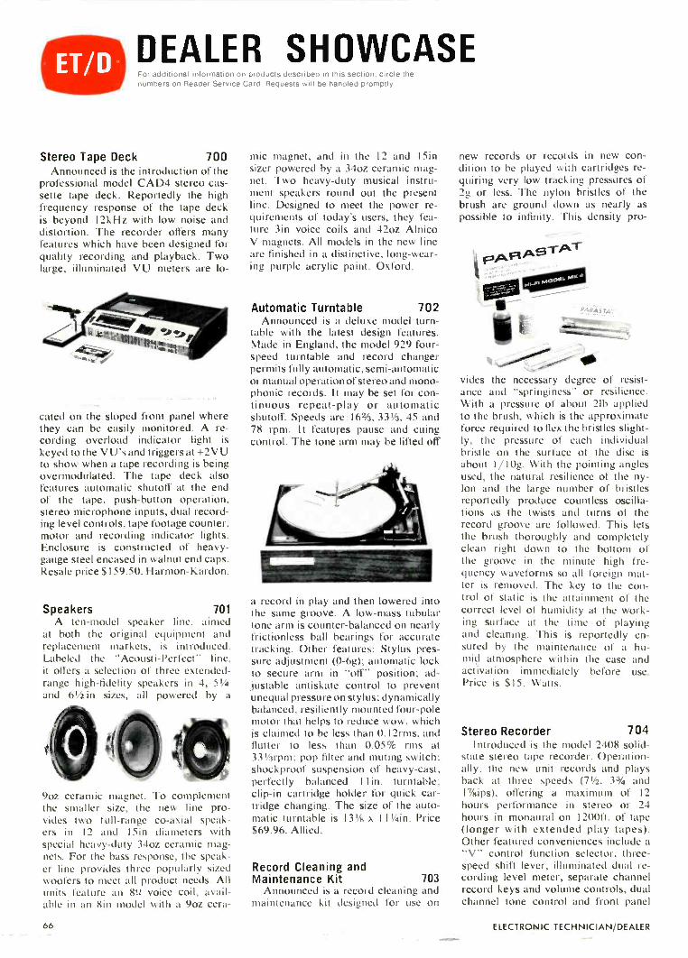
DEALER SHOWCASEFor additional inforrliatiOn oil products described in this section. circie thenumbers on Reader Service Card. Requests will be handled promptly
Stereo Tape Deck 700Announced is the introduction of the
professional model CAD4 stereo cas-sette tape deck. Reportedly the highfrequency response of the tape deckis beyond 12kHz with low noise anddistortion. The recorder offers manyfeatures which have been designed forquality recording and playback. Twolarge, illuminated VU meters are lo-
cated on the sloped front panel wherethey can be easily monitored. A re-cording overload indicator light iskeyed to the V U's and triggers at +2V Uto show when a tape recording is beingovermodulated. The tape deck alsofeatures automatic shutoff at the endof the tape, push-button operation,stereo microphone inputs, dual record-ing level controls, tape footage counter,motor and recording indicator lights.Enclosure is constructed of heavy -gauge steel encased in walnut end caps.Resale price $159.50. Harmon-Kardon.
Speakers 701A ten -model speaker line, aimed
at both the original equipment andreplacement markets, is introduced.Labeled the "Acousti-Perfect" line,it offers a selection of three extended -range high-fidelity speakers in 4, 51/4and 61/2 in sizes, all powered by a
9oz ceramic magnet. To complementthe smaller size, the new line pro-vides two full -range co -axial speak-ers in 12 and 15in diameters withspecial heavy-duty 34oz ceramic mag-nets. For the bass response, the speak-er line provides three popularly sizedwoofers to meet all product needs. Allunits feature an Bit voice coil, avail-able in an Bin model with a 9oz cera-
mic magnet, and in the 12 and 15insizer powered by a 34oz ceramic mag-net. Two heavy-duty musical instru-ment speakers round out the presentline. Designed to meet the power re-quirements of today's users, they fea-ture 3in voice coils and 42oz AlnicoV magnets. All models in the new lineare finished in a distinctive, long -wear-ing purple acrylic paint. Oxford.
Automatic Turntable 702Announced is a deluxe model turn-
table with the latest design features.Made in England, the model 929 four -speed turntable and record changerpermits fully automatic, semi -automaticor manual operation of stereo and mono-phonic records. It may be set for con-tinuous repeat -play or automaticshutoff. Speeds are:16%, 331/3, 45 and78 rpm. It features pause and cuingcontrol. The tone arm may be lifted off
a record in play and then lowered intothe same groove. A low -mass tubulartone arm is counter -balanced on nearlyfrictionless ball bearings for accuratetracking. Other features: Stylus pres-sure adjustment (0-6g); automatic lockto secure arm in "off" position; ad-justable antiskate control to preventunequal pressure on stylus; dynamicallybalanced, resiliently mounted four -polemotor that helps to reduce wow, whichis claimed to be less than 0.12rms, andflutter to less than 0.05% rms at331/2rpm; pop filter and muting switch;shockproof suspension of heavy -cast,perfectly balanced 11 in. turntable:clip -in cartridge holder for quick car-tridge changing. The size of the auto-matic turntable is 131/F4 x 111/4in. Price$69.96. Allied.
Record Cleaning andMaintenance Kit 703
Announced is a record cleaning andmaintenance kit designed for use on
new records or records in new con-dition to be played with cartridges re-quiring very low tracking pressures of2g or less. The nylon bristles of thebrush are ground down as nearly aspossible to infinity. This density pro-
vides the necessary degree of resist-ance and "springiness" or resilience.With a pressure of about 2Ib appliedto the brush, which is the approximateforce required to flex the bristles slight-ly, the pressure of each individualbristle on the surface of the disc isabout 1/10g. With the pointing anglesused, the natural resilience of the ny-lon and the large number of bristlesreportedly produce countless oscilla-tions as the twists and turns of therecord groove are followed. This letsthe brush thoroughly and completelyclean right down to the bottom ofthe groove in the minute high fre-quency waveforms so all foreign mat-ter is removed. The key to the con-trol of static is the attainment of thecorrect level of humidity at the work-ing surface at the time of playingand cleaning. This is reportedly en-sured by the maintenance of a hu-mid atmosphere within the case andactivation immediately before use.Price is $15. Watts.
Stereo Recorder 704Introduced is the model 2408 solid-
state stereo tape recorder. Operation-ally, the new unit records and playsback at three speeds (71/2, 33/4 and17/sips), offering a maximum of 12hours performance in stereo or 24hours in monaural on 1200ft. of tape(longer with extended play tapes).Other featured conveniences include a"V" control function selector, three -speed shift lever, illuminated dual re-cording level meter, separate channelrecord keys and volume controls, dualchannel tone control and front panel
66 ELECTRONIC TECHNICIAN/DEALER

stereo headphone jack. An end -of tapeautomatic stop switch providesprofessional -type recording and play-back capabilities. Although completewith power amplifiers, the unit also
can be used with existing stereo am-plifiers and speakers. Wow and flutteris reportedly less than 0.2% rms at7/zips, output power 8w total peak (4wper channel), signal/noise ratio betterthan 40db, frequency response 50Hzto 15kHz at 7Y2ips, separation betterthan 40db and cross -talk better than55db. The unit is housed in a leatherpattern vinyl -over -wood cabinet andweighs 281b. Suggested list price is$199.95. Craig.
Antenna Display 705Announced is the availability of a
compact new self -merchandising dis-play of exact replacement portable TVantennas. The display requires only2ft. of floor space, yet holds as manyas 360 exact replacement antennas.The company is said to be the only one
in the industry to offer a complete lineof exact replacement antennas for allmakes and models of portable TV sets.Each antenna is placed on a skin -packdisplay card with the make and modelnumbers of the TV sets it serves promi-nently indicated. The revolving displayis shipped in three sections that re-portedly can be assembled in just a
few minutes. It includes eye -stoppingsigns that explain the advantages ofthe antennas. JFD.
Component Turntable 706Introduced is the component turnta-
ble, the latest in the company's stereomodular line. It includes a four -speed,
1 1 in. turntable with a four -pole motor,magnetic cartridge and diamond stylus.It also has antiskate and cuing con-trols, low mass tone arm, automaticshutoff and lock, and output jacks forstereo system components. The turn-table is complete with a bookshelf size
base and tinted plastic dust cover. Also,nine color TV sets, eight stereo instru-ments have been added to the line.Suggested retail price $79.95. Sylvania.
Is Johnson's new23 -channel Messenger 123at $169.95 Legal?
You be the Judge.Is it unfair competition for Johnson to produce a 23 -channelsolid state unit with the incomparable _ohnson "talk -power'for less money than you had to pay yesterday for a 12 -channelulit with crystals?
Is there a law against operating a rig whose specifications areclose to theoretical perfection-such as 0.4 microvolt sensitiv tyand sharply filtered 7 kHz selectivity?
Is it a crime to build in a special speech compression circuit forulsurpassed voice intelligence? Or the famous Johnsonh gh-efficiency noise limiter that virtually wipes out ignition ando:her extraneous raciated interference
We think you'll agree: For sheer value, Messenger 123 is theexception to the rule.
E. F. JOHNSON COMPANYWASECA, MINNESOTA 56093
. for more details circle 12E on postcard
FEBRUARY 1969 67

ie COLORFAX
MOTOROLA
Color TV Chassis TS915/TS191Service Tips
Symptom: CRT warm-up is slowwith the quick -on switch in the "on"position. A low brightness condition isevident and the CRT has appearanceof being soft (gassy). Cause: Insuffi-cient CRT heater voltage when set ison. Solution: Turn set on. Make noteof picture brightness and the intensityof CRT heaters. Set quick -on defeatswitch (rear of set) to off position. Ifthe picture brightness or CRT heaterintensity decreases, the master on/offswitch on front of set is defective (PartNo. 40P65171A81). Alternate check:Measure filament voltage on CRT. Itshould be about 3.5v when set is turnedoff, but in the standby position. Turnset on. Filament voltage should in-crease to 6.3v. If it doesn't, the masteron/off switch is defective.
Do not adjust ABL and/or G2 con-trols above normal to overcome lowCRT heater voltage. Over adjustmentmay cause excessive loadpanel (F). CRT may be damaged ifoperated with low heater voltage.
RCA VICTOR
Color TV Chassis CTC40 -theMOS Field -Effect Transistor
The KRK 142 tuner used in theCTC40 color chassis features an RFamplifier stage using a special typedual -gate MOS-FET transistor. Tothose not acquainted with this terminol-ogy, the MOS-FET is a Metal OxideSemiconductor -Field Effect Transistor.Because a solid-state device of thistype has not been previously used, itwould be wise to acquaint the readerwith some interesting facts about thisnew transistor.
The MOS-FET combines the advan-tages of solid-state devices (small size,low power consumption and mechani-cal ruggedness) with a very high inputresistance and linear over-all transfercharacteristics that closely resemblethose of a pentode vacuum tube. Inmany respects an MOS-FET controlselectron flow by the action of an elec-trostatic field. This implies that thesignal input need not supply current,as is necessary in the case of drivingthe base of a transistor.
The input element of the MOS-FET
GATE
consists of a metal control electrode(gate) that acts as one plate of a capaci-tor-the other plate consists of thesemiconductor material. A charge ap-plied to the gate electrode produces anequal but opposite charge in the semi-conductor layer (channel) located di-rectly beneath the gate. This charge inthe channel area controls conductionbetween two additional electrodesknown as the source and drain, which
INSULATION(3105 )
SOURCE DRAIN
CHANNEL
P
SUBSTRATE
are applied to the opposite ends ofthe channel. As shown in the illustra-tion, the gate electrode of a MOS-FETis comprised of a metallic contact sepa-rated from the semiconductor channelby an extremely thin layer of siliconoxide which acts as an insulator (ca-pacitor dielectric). In the depletion typedevice illustrated, a negative chargeapplied to the insulated gate electrodewill deplete the source -to -drain channelof electrons. When a positive charge isapplied to the gate electrode, conduc-tivity will increase, resulting in in-creased electron flow. Because thesource -drain current is controlled en-tirely by varying the electrostaticcharge on the gate control electrode, nocurrent is required to bias the input ofthe device. Therefore, the MOS-FEThas an extremely high input resistance.
N -CHANNELDEPLETION - TYPE
D
B
S
The manufacturing processes used toproduce MOS transistors are similarto those used for high-speed siliconswitching transistors. Production startswith a lightly doped wafer of P typesilicon material. After a polishing oper-ation, the wafer is oxidized in a furnaceand photo -lithographic techniques are
used to etch away the oxide coating,exposing bare silicon in the source anddrain regions of each of the multitudeof transistors that are being formed onthe wafer. The source and drain regionsare next formed by diffusing an N typematerial such as phosphorus into thewafer.
This diffusion operation forms abridge (channel) between the sourceand drain electrodes.
The wafer is again oxidized to coverthe bare silicon regions and a secondphoto -etching step removes the oxideoverlaying the contact regions. In thenext step, metal is evaporated over theentire wafer and another photo -etchingstep removes all metal not needed toproduce ohmic contacts to the source,drain and gate electrodes. Finally, themany MOS-FET's on the wafer aremechanically separated and mountedon individual headers. Connectionwires are then bounded to the metal-ized regions and each unit is hermeti-cally sealed in its case. Courtesy ofRCA Sales Corp.
WESTINGHOUSE
Color TV Chassis V8001 - AutomaticChroma Control and ColorKiller Circuit Description
Automatic Chroma Control (ACC)maintains the chroma amplifier outputby establishing feedback from the emit-ter of Q501.
When a color signal is received, anominal -5v is developed across R530,R531 and fed to the base of Q50 I.Voltages at the base and emitter ofQ501 will vary depending on the mag-nitude of the burst. This sets up a vari-able forward bias on the base of Q501and the emitter voltage varies in pro-portion to this changing base voltage.A part of the changing emitter voltageis fed back to the grid of the chromaamp thus changing the bias.
A burst signal of lower magnitudedevelops a lower voltage on the resis-tors R530, R531, which in turn pro-vides a lower base voltage and therefore,less conduction of Q501.
A burst signal of higher magnitudedevelops a higher voltage across resis-tors R530, R531, in turn providing ahigher base voltage to Q501. Underthis condition, the transistor will con-duct more. Accordingly, the emittervoltage of Q501 will also go up or downdepending on the magnitude of theburst signal on the base.
During B/W transmission, only thelocal 3.58MHz oscillator signal is fedto the diodes X502 and X503. The out-put across R530, R531 is zero voltsand fed to the base of Q501. Now, withthe base voltage more positive thanthe emitter, the PN P transistor is cut off.
The function of the color killer is to
68 ELECTRONIC TECHNICIAN/DEALER

cut off the bandpass amplifier whencolor is not being transmitted by thestation. Therefore, the color killer is aswitching operation, either conductingor non -conducting. The color killer andACC are closely related in this set. Infact, the color killer is activated byoperation of the ACC amplifier whichis fed by the killer detector diodes.
T 501SUNDTTRANS
)11
J
C521
C 5511
X502 INPUT 3.5SM* OSC.
C 525 X 503
N 515
23V
A.C.C.5601
R 53T OUTPUT TOGRID OF
CHROMA
AMP
In some color television chassis, thecolor killer is cut off when color in-formation is being received and thebandpass amplifier conducts. In the14in. chassis, however, the color killertransistor conducts during color trans-mission. To understand the operationof Q500, we will start from a conditionwhere no color is being transmitted.With no burst signal present at thekiller detector diodes, X502 and X503,the only signal present is the 3.58MHzof the receiver oscillator; zero voltageis developed across the balanced re-sistors R530 and R53 I. Therefore zerovoltage is fed to the base of Q501, aPNP transistor. With zero at the baseand (-.1v) at the emitter, the transistoris cut off.
The emitter of Q501 is coupled tothe base of Q500 by R533. With Q501cut off, zero voltage is applied to thebase of the PNP transistor Q500, andQ500 is cut off. The collector voltagewhen Q500 is cut off is -12v. This nega-tive voltage on the cathode of X506forward biases the diode and the nega-tive voltage is fed to the grid of thebandpass amplifier, V12A.
0 500COLOR KILLER
A NAV SIGNAL COLOR SIGNAL * OV
. -.TIV
8619 8634
R530KILLERAIN
TO GRID OFSANDALS{ AMP
This bias, when applied to the gridof the bandpass amplifier drives thegrid well into the cut-off region. There-fore, no color information or noise canget through to the demodulators.
With a color program being received,the burst amplifier and transformer willhave a signal present to feed into thekiller detector diodes which are stillreceiving the 3.58MHz signal from theoscillator. The output of the killer de-tector is a negative 5v with a strongcolor signal being received.,
The tuning of the receiver and the
amount of burst received from thetransmitting station will determine thevoltages being applied to the ACC andchroma amplifier. Use of a color bargenerator while troubleshooting thesecircuits will stabilize the readings.
With -5v on the base of Q501, it willconduct, causing a voltage drop acrossR525 of approximately -2v. This volt-age, when fed to Q500 through R533,places approximately -0.7v on thebase, thereby turning on Q500 as youwould a switch.
Therefore, the center of the two 15Kemitter resistors, acting as a voltagedivide, is fed to two places. It is fedto the grid of the chroma amplifierwhere the voltage will contribute tothe bias and vary the gain of this tubeaccording to the amount of burst re-ceived by the killer diodes. It is alsofed to the base of the color killer, Q500,which is turned on by this negativevoltage. The collector of Q500 is re-duced to zero from -12v by currentflowing through the collector resistor,R534. With zero volts on the cathodeof diode, X506, it is now non -conduct-ing and an open circuit. With no addi-tional bias added to the grid of thebandpass amp from Q500, the bandpassamplifier tube will now conduct, pass-ing color. Transistors and diodes areused, giving the chassis solid-statereliability.
NEW FROM INJECTORALL
HERE'SPROOF!PROOF that "SUPER100" tuner cleaneris BETTER!
Tested by a leadingindependent laboratoryagainst competitiveproducts!
fires' SUPER 100 A B C
CLEANING Excellent Good Fair Fair
LUBRICATION Good Filr Fair Poor
PLASTIC ATTACK None None None None
FLAMMABILITY None None None None
CONDUCTIVITY None None Slight Slight
ANTI -STATICPROTECTION Excellent Fair Poor Poor
DRIFT None Slight Yes Yes
SUPER 100 TUNER CLEANER . . . forCOLORand Black and White TV tuners6 oz. spray can with INJECTORALL steelneedle CAT. NO. 100-6 net $1.95Buy it at your Electronic Dealer.For free catalog on the complete line,write to:
INJECTORALL ELECTRONICS CORFGreat Neck, New York 11024
tor more details circle 123 on postcard
Portable"computer"for electronicsmen. -
KA
WANT FAST ANSWERS to math and electronics prob-lems? Now, compute them in a flash with this
new Electronics Slide Rule.Calculate resonant frequencies, solve inductive
or capacitive reactance problems, find reciprocalsfor resistance formulas, locate decimal points-allin just seconds, without pencil and paper.
Whiz through regular math problems, too: multi-plication, division, square roots, logarithms, eventrigonometric functions.
Sturdy 12 -inch, all -metal slide rule comes com-plete with handsome leather carrying case-plus 4 -lesson instruction course. Deliberately priced low asour way of staking friends with electronics men.FREE booklet gives full details. Mail coupon belowtoday.
Mail Coupon for FREE Booklet
C I E Cleveland Institute of CI lac1776 East17th Street. Cleveland. Ohio 44114
Please send me, without charge or obligation, your book-let describing the Electronics Slide Rule and 4 -lessoninstruction course. Also free if I act at once - a handy,pocket -sized Electronics Data Guide.
Name
Address
(Please Print
City _ State ZIPAccredited Member National Home Study Council
A leader in Electronics Training Since 1934 ET 128
FEBRUARY 1969
. -or more details circle 113 on postcard
69

NEW PRODUCTSFor additional information on products described in this section, circle thenumbers on Reader Service Card. Requests will be handled promptly
CRT Rebuilding Equipment 707
Introduced is the CRT Color Cham-pion. The equipment reportedly willrebuild all types of picture tubes, coloror B/W, using standard components.According to the manufacturer, the
SEALING MACHINE
nominal low cost of operating the re-building equipment will offer the serv-ice technician an excellent profit return.Free installation and training is offeredanywhere in the continental UnitedStates. The CRT plan offers everythingrequired to get into this profitable busi-ness with a reasonably small invest-ment. The profit from the tuberebuilding business is said to exceedthe initial investment. CRT.
Vectorscope Indicator 708
Introduced is a new vectorscopeindicator, Model V5 for use with anystandard color bar generator usingthe 10 bar keyed -rainbow color sig-nal. The vertorscope is an essentialinstrument for service technicianswho are now trying to service colorTV without a complete vectorscope-color bar generator unit. With thisinstrument and a color bar genera-tor, the serviceman reportedly cancheck and align bandpass-amplifiercircuits as well as demodulators toany angle: 90, 105 or 115deg, and pin-point troubles to a specific color cir-cuit. An improper vector pattern loca-
lizes the trouble to the particular cir-cuit affecting either vector amplitude,vector angle or vector shape. The vec-
111111111,111°H'
torscope indicator reportedly checkscolor amplifier gain, adjusts color synccircuits and allows proper centeringof the hue control. Size: 7 3/8 in x4 1/4 in x 7 5/8 in.; weight 51b. Newprice is $79.50. Lectrotech.
Feed -Through Wall Plates 709
Feed -through wall plates, design-ed for ease of installation, eliminat-ing time-consuming connections atthe wall, are introduced. Althoughespecially useful for multi -unit MATV-CATV systems, they adapt to anyinstallation not requiring a connec-
tion at the wall. The new simple designfeatures a single hole versatile enoughto accept TV coax, telephone line,audio speaker line, rotor lead-in, cir-cular cable or other wire up to 1/4inOD. Mounting on any surface is accomp-lished with two wood screws, togglebolts. Mosley F-9 brackets (standardin M-1 PK) or standard ac electricaloutlet boxes. Units are available indecor -blending standard ivory. Mosley.
Meter Attachment 710
A new, low-cost meter attachmentcapable of converting Millivolt Com-mander instruments (and other 1052
centerscale meters) to read resistancesof onefl and less is announced. Theunit will convert instruments to readthe value of voltage dropping resistorsin solid-state power supplies as well asfor testing transformerless transistor-ized audio power amplifiers where theoutput is normally in the 0.4 to 0.62range. The model 870-3 unit also fea-tures nearly complete negation ofnormal in -circuit lead resistance. Addi-tionally, the device under test (MOS-
FET, IC, etc.) is now fully protectedagainst accidental burnout; current hasbeen limited to 100ma across 112.
Operationally, the meter is simplyswitched to 0.lvdc range and zero -adjusted in normal manner. The adaptercable is connected to meter input. Withtest leads unshorted, the attachment's"test" button is depressed and metersimultaneously adjusted for full-scaledeflection. Now the test leads can beconnected to the device being measuredand the "test" button again depressed.To read out 0 to 152 resistance value,merely observe meter deflection anddivide by 10. Price is $14.95.Amphenol.
CB Antenna 711
A dual gain, double dipole citizensband antenna with omni-directionalgain is announced. The Model M217Super Collinear antenna is claimedadjustable to radiate a directionalsignal with an 8db rejection of inter-ference in any direction chosen bythe user. The antenna achieves itsperformance using two 1/2 -wave length
70 ELECTRONIC TECHNICIAN/DEALER

dipole radiators, one above the other,with 1/8 -wave length separation. Thedouble radiation patterns are addi-tive and the composite pattern is low-ered toward the ground without needfor ground plane rods. The result isa "dual -gain" effect --in excess of 5db.The upper 1/2 -wave dipole is 17ft longand mounts in a conventional man-ner. The second dipole is formed bya 22ft cable 1/8 -wave separator. The5db omni-directional gain is achievedby mounting the cable dipole at an
angle of less than 30deg from verti-cal beneath the antenna base. To re-duce directional interference, a for-ward pattern of 5db gain with an 8dbfront -to -back ratio can be achieved byincreasing this angle to between 45and 75deg.
The antenna's phasing transformerprovides resonance over the entire23 channels. VSWR is 1.5 to 1 or less.A new "Stati-lite" ball is used to de-crease receiver noise. The antennahas a direct ground for lightning pro-tection. Impedance: 50 0: weight 81b.Antenna Specialists.
Sweep and Marker Generator 712A VHF sweep, UHF sweep, crystal
controlled marker generator and amarker adder are incorporated in asingle instrument. A complete align-ment instrument, the SM152 provideslinear sweep from 10MHz to 920MHzfor all TV and FM work. Its sweepfrequency generator is calibrated inMHz and also in TV channel numbersfor exceptionally fast use. An exclusivefeature is the sweep width calibratedfrom 0.3MHz to 15MHz with calibra-tion unaffected by the frequency gener-ated. A swept 3.58MHz chroma signaladded to RF output checks chromaresponse in the over-all system throughIF and bandpass amplifiers. Chroma isalso available at the chroma outputjack for direct injection into bandpassamplifiers. Crystal -controlled markersare provided for both IF and RF. Bypushing a button, a crystal -controlledmarker appears on the sweep responsecurve. Markers for IF and chroma
Having trouble gettingTransistor replacementsfor manufacturer'spart numbers? ?
MOTOROLA'
foof "0/oZ..
\-\\vi
1;1
Quick! Get a copy of the new MOTOROLA HEPCross Reference Guide, number HMA 07-4!It lists replacements for over 18,000 different1N, 2N and hard to get manufacturer's HouseNumbers for entertainment and consumerproducts equipment, and covers transistors,FETs, integrated circuits, Zener diodes, rectifiers,germanium diodes, SCRs, triacs, dual diodes,rectifier bridges and unijunction transistors.Hundreds of Japanese and other foreignmanufacturer's types are included.
Motorola HEP has replacements for"hard to get- parts that you can'tfind anywhere else.
End those replacemeit problems today. Seeyour Motorola HER dis:rihutor and pick up yourFree Copy of the new Motorola HEP CrossReference Guide.
Get HEP by MOTOROLA
MOTOROLA HEP SEMICONDUCTORSP. 0. BOX 20924 / PHOENIX, ARIZONA 85034
FEBRUARY 1969
... for more details circle 137 on postcard
71

ftiqp ix, cm war 1AUTOMATIC
STAPLE GUNSCUT WIRE & CABLE
INSTALLATION COSTS. without cutting into insulation!
SAFE! Grooved Guide positions wire forproper staple envelopment! Grooved DrivingBlade stops staple at right depth of penetrationto prevent cutting into wire or cable insulation!
No. T-18-Fits wires up to3/16" in diameter.
BELL,TELEPHONE,
THERMOSTAT,INTERCOM,BURGLAR
ALARMand other lowvoltage wiring.
Uses T-18staples with 3/16" round crown
in 3/8" leg length only.
4-No. T-25-Fits wires up to1/4" in diameter.
Same basic constructionand fastens samewires as No. T-18.
Also used forRADIANT
HEAT WIRE
Uses 1-25 stapleswith 1/4" round crown in 9/32",3/8", 7/16" and 9/16" leg lengths.;.)T-18 and T-25 staples also available in Monel andwith beige, brown and ivory finish at extra cost.
No. T -75 --Fits wires and cablesup to 1/2" in diameter.
RADIANT HEATCABLE,
OF CABLE,WIRE CONDUIT
COPPER TUBINGor any non-metallic
sheathed cable.Also used as
DRIVE RINGSin stringing wires.
Uses T-75 staples with 1/2"flat crown in 9/16", 5/8" and
7/8" leg lengths.
Arrow Automatic Staple Guns save 70% in timeand effort on every type of wire or cable fasten-ing job. Arrow staples are specially designed withdivergent -pointed legs for easier driving androsin -coated for greater holding power! All -steelconstruction and high -carbon hardened steelworking parts are your assurance of maximumlong -life service and trouble -free performance.
Ask your Electrical Supply Dealeror write for further details.
Saddle Brook. New Jersey 07663
"Pioneers and PacesettersFor Almost A Half Century"
NEW PRODUCTS
alignment are 39.75, 41.25, 41.67,42.17, 42.67, 44.25, 45.75, 47.25, 4.5,3.58 and 3.08MHz. Markers at the RFvideo carrier on channels 4, 5, 10 and13 are also available at the push of abutton. The sound RF carrier is ob-tained by pushing the 4.5MHz pushbutton on any RF channel. An extrapush button and crystal jack are pro-vided to add other crystal mark points
if needed. Special FM crystal markersof 10.7, 10.6 and 10.8MHz are gener-ated simultaneously to view the centerFM frequency with 100kHz markers oneach side when viewing the "S" curveduring alignment. This is claimed tosave considerable time when determin-ing bandwidth in FM stereo alignment.The instrument also provides a specialvariable marker generator for IF spotalignment of old sets. A variable oscil-lator from 39 to 48MHz is available.
The SM152 features post markerinjection on all markers. An oscil-loscope is the only other equipmentneeded for complete alignment. Price$349.50. Sencore.
ETV Tapoffs 713
A new series of tapoffs designedto meet the needs of educational TVis introduced. The dual output tap -offs are mounted on stainless steel
plates. They can handle all UHF, VHF,FM and sub -channel TV channels,plus closed circuit TV and 2.5GHz
WHYSEND TOJAPAN?
You Can Get Same DayShipment of Replacement
Heads for Norelco andMost Import CassetteTape Recorders From
MICHIGAN MAGNETICSA DIVISION OF VSI CORPORATION
VERMONTVILLE, MICHIGAN 49096Telephone (517) 259-8911
FREECATALOG
Send forYour Copy of
Consumer AudioCatalog # 680
. for more details circle 134 on postcard
QUIETROLEmf list
ors,
gore
wriou
The Original Controland
Switch Lubri-Cleaner
The oldest. most
reliable and efficientproduct obtainable for
positive lubrication and
cleaning of TV Tuners.
Controls and Switches.Harmless to plasticsand metals. Zero effects
on resistance and
capacity. Non-inflam-
mable-non-conductive-non-corrosive.
The Choice of Better
Servicemen, Everywhere.
For Color andBlack and White
Available in Aerosol or BottleProduct of
QUIETROLECOMPANY
Spartanburg, South Carolina
. for more details circle 104 on postcard
72
for more details circle 142 on postcard
ELECTRONIC TECHNICIAN/DEALER

ETV signals. Called "DuoTaps," theunits are back -matched to accept CCTVcamera, video tape recorder or com-plete ETV studio inputs. The tapofffits into any standard electrical 'out-let box. They use SO -239A with Tef-lon inserts as output connectors andF fittings for through line connectors.The tapoffs pass dc to 890Mf Hz throughthe trunk line, but block power to theirtaps. Thus, they can be used in sys-tems including cable powered lineextenders and other accessories. A-side from back -matching, the outstand-ing electrical feature of the units isthat they cause relatively low signalloss. They are available with isola-tions of 12db, 17db and 23db, flat ac-ross the entire sub, VHF, FM andUHF spectra. Designated Models a5601 (12db), D-5602 (17db), and D-5603(23db), the tapoffs list for $10. JFD.
Solid -State Power Supply 714Two bench -type regulated dc power
supplies representing entrance intothe solid-state power supply marketare announced. The WP -700A (singleunit) and WP -702A (dual unit) aresolid-state constant -voltage dc powersupplies that are reportedly ideallysuited for use in circuit design, servic-ing, industrial and educational appli-cations. The WP -700A and WP -702Aare identical, except that the WP -702Ais a dual unit with separate controls,
output terminals and meters for eachsection. The two sections of the WP -702A are electrically isolated fromeach other. Output voltage of the unitsis continuously adjustable from 0 to20v, at current levels up to 200i.ta. Thecircuit automatically limits the over-load current to prevent damage to thepower supply. The supplies will not bedamaged even if connected to an ex-ternal short circuit. A special over-load indicator lamp on the panel willbegin to glow when the current levelapproaches the 200µa rating and willglow brightly if the current exceeds2001.1a. A meter is provided to indi-cate either output voltage or currentlevel. The meter function is selectedby a convenient panel switch. Silicontransistors and diodes are used in thepower supplies. Circuit design featuresinclude a negative -feedback regulatorcircuit to maintain constant outputvoltage with low ripple.
/Venciazyj
Three convenient five -way output ter-minals (+DC, -DC, and GND) areprovided. The units are equipped witha three -wire ac power cord to permitconnecting the external circuit to thepower line ground using the "GND"terminal. The units are compact andlightweight with attractively designedfunctional panels. The WP -700A meas-ures 4 x 61/2 x 3in. and weighs 3 lb. TheWP -702A measures 6 x 12 x 3in., andweighs 3 Ib, l0oz. Both supplies haverugged metal cases finished with blue -gray hammertone enamel. The WP -700A shown is priced at $48 each andthe WP -702A is $87 each in quantitiesof one to four units. RCA.
Ta De Head Cleaner 715
A new aerosol -type cleaner for allaudio and video magnetic tape heads,guides and film gates is announced.The new product, Audio -Video TapeHead Cleaner, is said to be completelysafe for use on all types of recordingheads and will quickly remove all dirt,film and oxide buildup that detractsfrom the unit's performance. The newcleaner will not harm valuable tapes,tape coatings or the finish of the re-corder itself. When used as directed,the cleaner will not interfere withtransmission and may be safely appliedon running tape. The cleaner is non -
DISGRACEFUL44 Isn't it? The way Mercury shamelessly offers top
quality test equipment at such low prices. Comparethe features with costlier mode's and see how Mercurygives you top value for your dollar. It's Wonderful.,,
s129;5
Model 1101-DELUXE TUBE TESTER
For new Magnovals, Decals,Nuvistors, All Popular Pic
. _:1 Lure Tubes and most otherreceiving tube types. Checkstubes fcr dynamic cathoceemissior, shorts, grid leak-age and gas. Picture TubeAdapter. Exclusive 2 -point
Tigismoinimmir test principle safeguardsagainst obsolescence.
Kit-. $4995/Wired-56995 Kit-
Model 2000-MUTUAL CONDUCTANCE TUBETRANSISTOR TESTER
Tests all tube types, old and new, plustransistors. Tests Magnovals, Nuvistors,10 -pin Decals, Compactrons, Novars, 10 -pin types, foreign anc hi-fi tubes, thyra-trons and industrial types. Tests for truedynamic mutual condLctance (GM). Spotsshorts, leakage and gas. Tests Color andB/W picture tubes with use of MH-3AMulti -Head Adapter (optional). Leverswitch test principal overcomes obsoles-cence. Automatic line voltage regulation.
$3495/wired-s4995
Model 1100B-TUBE TESTER
Tests more tube typesthan any other testerin its price range.Tests for dynamiccathode emission,shorts, grid leakageand gas. Exclusivemeter bridge circuitfound only in moreexpensive testers. Pro-fessional quality atan economical price.
ALL MERCURY TEST EQUIPMENT GUARANTEED FOR ONE FULL YEAR!UPDATED TUBE TEST DATA AVAILABLE ON ALL UNITS.
MERCURY ELECTRONIU. CORPORATIONI
It.
. for more details circle 133 on postcard
73FEBRUARY 1969

Ten More PopularColor TV Coil Replacements
Cat. No. Function Manufacturer Part No.6355 Dynamic Convergence Admiral 94C305-66058 Chroma Bandpass Emerson 7205636356 Blue Phasing GE ET36X7896059 Burst Phase Hoffman 109-0317006357 Pin Cushion Motorola 24C65127A906060 Chroma Take -Off Philco 32-4878-26358 Horizontal Linearity RCA 1207946359 Horiz-Osc. & Waveform Silvertone 10-88-57150 Sound Take -Off Sylvania 50-16206-S6061 3.58 mHz Osc. Wells Gardner 9A2660-001
Write for your copy of Cross Reference Bulletin 1068
J.W. MILLER COMPANY5917 South Main Street Los Angeles, California 90003
MI YOUR LOCAL DISTRIBUTOR FOR THE FULL LINE OF RI AND IF COILS, CHOKES, FILTERS AND TRANSFORMERS
. for more details circle 135 on postcard
esg- 'S NEW . . .
'82' CHANNELHEAD -END AMPLIFIERIS EXACTLY WHATYOU NEED!
JFD's Model SL -3155 '82' channelcolor perfect Head -End Amplifier isan industry first. This new and uniquesolid state unit guarantees totalUHF/VHF/FM - FM Stereo reception.
30 db gain - over 54 dbmv out-put capability.Automatic circuit breaker cutoffto detect shorts on the line.17 volt DC spare output for power -
SMOOTHJFD ELECTRONICS CO./SYSTEMS
ing preamplifiers and up to 10JFD SMOOTHLINE amplified ac-cessories.
Like SL -3155, V-3130 VHF andU-3140 UHF Head -End Amplifiers aresolid state and set a new high indus-try standard.For complete details - write forcatalog SYS-68 or see your local JFDrepresentative.
DIVISION5th Avenue at 62nd Street Brooklyn, N.Y. 11219/Phone 212-331-1000
See us at the AASA Show Booth #11287 Haddon Hall Exhibition Hall. . for more details circle 127 on postcard
74 ELECTRONIC TECHNICIAN/DEALER
NEW PRODUCTS
toxic, non-conductive, non-flammableand makes the proper care and main-tenance of costly recording equipmenta safe, simple task. The new cleaner
or _AL"- --aft-11 NO 0421
AUDIO -VIDEO
TAPE HEADCLEANER
!1.1.4cyotIB.F.c. i;SO
is being offered in a king-size 16ozaerosol can equipped with a 6in sprayextension enabling the user to pin-point the spray at normally hard -to -reach tape heads. Net price is $2.35per can. G. C. Electronics.
Base Station Antenna 716A series of professional base station
antennas for use in the 25 to 50MHzfrequency range is announced. De -sighed to meet or exceed all EIAStandards for base station antennas
(RS -329), the ASP -600 series willhandle 500w of input power with re-serve. A true 3db omni-directional gainprovides reliable system operation. A

new high -strength aluminum alloy isused in the radial and support tubes.This material, combined with the fiber-glass reinforced coil jacket whichshares the flexural load of the wind, issaid to provide a 100mph load ratingwith a 1.65 safety factor. A moldedneoprene suspension gasket separatesthe base tube of the radiator and thetransformer to seal out moisture for thelife of the antenna. The braided trans-former jacket design also provides ex-cellent ultraviolet stabilization char-acteristics. The antennas are dcgrounded to minimize precipitationstatic and reduce receiver noise inter-ference. Tunable radials provide formaximum decoupling of RF. Threemodels in the series cover 25 to 28, 30to 40 and 40 to 50MHz. AntennaSpecialists.
Oscilloscope 717Announced is the model LBO -52B,
a 5in. oscilloscope with a bandwidth ofdc to 10MHz and featuring hybridcircuitry. The 10mv/cm sensitivitymakes it especially suitable for exam-ining low level signals such as in tunersand IF amplifiers. The linear widesweep range has automatic synchro-nization. The vertical and horizontalinputs are direct coupled with push-pullamplifiers for distortionless display.The unit provides vector pattern dis-
play for color TV circuits to view pat-terns at the chroma detector and toalign the chroma section of color TV.Specifications: Vert. Axis; deflectionsens. 10mv P-P/cm or better. Band-width, at -3db dc: dc to 10MHz. ac:2Hz to 10MHz. Input control X 1, X10,X100, X1000 and fine adj. Calibrationvoltage 0.05v P -P at line frequency.Horiz. Axis: sens; 300mv P-P/cm orbetter. Bandwidth, at -3db dc: dc to500 kHz. ac: 2Hz to 500KHz. InputControl X 1, X10 and fine adj. SweepCircuit Frequency: 1 Hz to 200kHz insix steps; H -TV at I 5.7kHz/2. Syn-chronization: Int + E Ext and Line.Size and weight: 10'/2 x 8 x 161/2in., 24lb. Price is $199. Leader.
TRANSISTORSNOWCHECK
INCLUDING FETs IN OR OUT OF CIRCUIT!Leave it to Sencore to come out with the first and only complete transistortester. It's the new TF151 that checks both regular and field effect tran-sistors, both in and out of circuit. Just flip the control knob to the left forregular transistors and to the right for FETs. It's as simple as that.
TF151
Check all regular transistors in orou- of circuit for Ac Beta, and outof zircuit for Icso leakage.
Provides an increased currentchack for more accurate tasting ofhigh power transistors.
Provides a special test b' criticalRF transistors.
<MAN
-ests all single and dual gate FETsfor true mutual conductance in orout of circuit. Gm gain is read ininicromhos.
Checks FETs out df circuit torloss leakage in microamps.
Provides special Icss (zero bias)current checks for industrial "cul-'ing."
aVAIN 10.)
E
2
PL : (2) SP
(1) A special check for crystal diodes in or out of circuit forproper front
ownto
backexclusive
ratio.transistor/FET reference book that
lists the transistor anc FET gain and leakage figures astested by the TF151. Over 12,000 listed.
With just the "flip of a switch" the Sencore TF151 can test ALL yourtransistor problems in o- out of circuit. Stop by your distributor today andask for a free demonstration .. you'll be convinced too! only $12950
O. 1\1 CD 1=1NO 1 MANUFACTURER OF f, t, I (.2UIPMFNT
426 SOJTH WESTGATE DRIVE. ADDISON. ILLINOIS 60101... for more details circle '52 on postcard
FEBRUARY 1969 75

FARSUPElgaTOANY
NT
ORVOM--andforlessmoney
only
$69.95
*OC
.1140 041(0IC INS)
AC ,P 1)
VikklNPUT IOW& 14 PrINPUT -IOW& 19 Pr
ICCl/11A
CD 1=t
FIELD EFFECT METER
ON
ramFE 14
OHM,no
NEW FIELD EFFECT MULTIMETERHere is the revolutionary new approach to circuit testing, the solidstate Sencore FIELD EFFECT METER. This FE14 combines theadvantages of a VTVM and the portability and versatility of a VOMinto a single low-cost instrument. This is all made possible by theuse of the new space age field effect transistor that is instant inaction but operates like a vacuum tube in loading characteristics.Compare the features of the FIELD EFFECT METER to your VTVMor VOM.Minimum circuit loading - 15 megohm input impedance on DC is better than aVTVM and up to 750 times better than a 20,000 ohm per volt VOM - 10 megohminput impedance on AC is 20 times better than a standard VTVM. The FIELDEFFECT METER is constant on all ranges, not like a VOM that changes loadingwith each range.
Seven AC peak -to -peak ranges with frequency response to 10MHz. Seven zerocenter scales down to 0.5 volt. Five ohmeter ranges to 1000 megohms. DC currentmeasurements to 1 ampere. Full meter and circuit protection. Mirrored scale.Low current drain on batteries - less than 2 milliamps. Built-in battery check.Unbreakable all -steel vinyl clad case. Optional Hi -Voltage probe adds 3KV,10KV and 30KV ranges with minimum circuit loading for greatest accuracy in theindustry... ;9.95.
FE16 HI -ACCURACY FIELD EFFECT METER.All of above features, plus unmatchedaccuracy - 1.5% on DC, 3% on AC. High -stylemeter, knobs, and special meter -tiltinghandle. $84.50.
76
1\1 CD F=1NO. I MANUFACTURER OF ELECTRONIC MAINTENANCE EQUIPMENT
426 SOUTH WESTGATE DRIVE. ADDISON. ILLINOIS 60101
for more details circle 153 on postcard
NI7cY), from
"IN - CIRCUIT"
CURRENT CHECKEREliminates most common cause of"callbacks" (unstable focus,shrinking pictures, etc.)! Shouldpay for itself onnext months'calls alone!
Nothing else like the HC -8 available!Tune horizontal drive and linearityfor "dip"-- and in seconds you'vegot best possible focus, width and sta-bility at minimum cathode current.Makes convergence adjustmentsfaster, easier- longer lasting!Especially useful on color TV where aslight misadjustment of horizontallinearity or efficiency coils drives cath-ode currents sky high! 5 pre -wiredsockets for all popular hori-
Model HC -8zontal output tubes lets youplug into circuit fast- no clip- )3450ping or unsoldering of leads! Net
ASK YOUR DISTRIBUTORor write for full details.
SECOELECTRONICS CORP.
1003 Second St. So. Hopkins, Minn. 55343
for more details circle 155 on postcardELECTRONIC TECHNICIAN/DEALER

NEW PRODUCTS
Test Adapters 718Four new BNC plug conversion
adapters are introduced. These adaptersmake it possible to convert coaxial testcables fitted with BNC plugs to any offour other plug types. The model 1297converts to standard 1/4in. diametershielded phone plug; model 2798 con -
verts to 0.250in. diameter phone plug(PJ-015/WE 310) for equipment usingthree -circuit phone jacks; model 2957converts to shielded phono plug; model2990 converts to shielded banana plugfor equipment having banana jacks orbinding posts. Net priced: model 1297,$5.85; model 2798, $6.85; model 2957and 2990, $2.50. Pomona Electronics.
Portable TV 719Introduced is a B/W TV Model
TV I IOU. This solid-state model hasan 11 in screen (measured diagonally)
and is said to produce a sharp, clearpicture for small or large audiences. Asnap -in sunglass filter reportedly givesbright, glare -free reception in any light.It operates on regular house current,a Sony battery or car/ boat 12v bat-tery. With a choice of power, theTVIIOU is expected to be popular inhomes, on boats, at beaches andcamps. The portable comes in blackwith silver trim. An earphone is pro-vided for private listening. Price$139.95. Sony.
CB Phone Patch 720Introduced is a phone patch that will
interconnect any base CB with the
telephone and thus reportedly extend aCB call to any telephone in the nation.
The unit is particularly important inemergencies for contacting police orother public safety and emergency
Continued on page 86
New idea in soup -columns from Argos...serves up superb
voice and music
Why not orderone out or. trialtoday? 1f ;t doesn'tmatch our claims-send it back tothe kitchen!
Beautiful new solution to thosesmall, multiple -use locationswhere full-size Sound Directorcolumns can't be justified - yetthe situation calls for prestige,faithful sound reproduction andversatility.Especially suited to restaurants,club rooms, schools and offices upto 60 feet, where speech qualitymay be critical one day and musicthe next.Unique contemporary "art frame"cabinetry in hand -rubbed, oil -finished genuine walnut. Sixspeakers, 16 ohms impedance. Re-sponse from 100 to 12,000 cps at30 watts.
Model ESD-1061an autnentic Sound Director sourd column from
PRODUCTS COMPANY600 South Sycamore St., Genoa, III. 60135
FEBRUARY 1969
. . for more details circle 103 on postcard
77

...the soldering toolsprofessionals depend on
Theoriginal Dual Heat
Soldering GunsPreferred by technicians for their
fast heating copper tips, exclusivetrigger -controlled dual heat, and highsoldering efficiency. Available in 3 watt-
age sizes, each with spotlight.
100/140 -watt Model 8200, 145/210 -wattModel D-440, and 240/325 -watt ModelD-550. Also in complete kits:
Utility Kit includes Weller100/140 watt gun, extra tips,tip -changing wrench, fluxbrush, soldering aid and solder.Model 8200PK
Heavy -Duty Kit features Weller240/325 watt gun withsoldering, cutting and smooth-ing tips, wrench and solder.Model D-550PK
Dependable MARKSMAN Ironsin a size for every job
Ideal for deep chassis work and continuous -duty soldering,Marksman irons outperform others of comparable size andweight. All five feature long -reach stainless steel barrelsand replaceable tips.
25 -watt, 13/4 -oz. Model SP -23 with I/8" tip (In kit with extra tips,soldering aid, solder-Model SP -23K)
40 -watt, 2 -oz. Model SP -40 with 1/4" tip 80 -watt, 4 -oz. Model SP -80 with %" tip 120 -watt, 10 -oz. Model SP -120 with 1/2" tip 175 -watt, 16 -oz. Model SP -175 with `3k" tip
Complete Weller Line includes replacement tips and solder
WELLER ELECTRIC CORPORATION, Easton, Pa.WORLD LEADER IN SOLDERING TOOLS
. . for more details circle 147 on postcard
NEWSOF THE INDUSTRY
Shure To BuildPlant in Phoenix
Shure Electronics of Arizona, Inc., a wholly ownedsubsidiary of Shure Brothers, Inc., a major manufacturer ofmicrophones, high fidelity components and related products,today broke ground for a new, ultra -modern assembly plantto be located at the intersection of 21st Ave. and CherylDrive in Phoenix.
Upon completion, the new plant will house a productassembly operation and a warehousing facility which thecompany has maintained in Phoenix for approximately twoyears in separate, leased locations. All of the approximately125 people presently employed by Shure in Phoenix willmove to the new building when it is completed early nextspring.
The new building will contain 63,400sq. ft., with ap-proximately 52,000sq. ft. devoted to pfoduction and 8000sq: ft. to personnel facilities, including a modern cafeteria.The balance of space will be occupied by administrativeoffices. All areas will be completely air-conditioned. A60,000sq. ft. employee parking lot will be provided adjacentto the building. The building site allows for ultimate ex-pansion of the plant to 170,000sq. ft.
Integrated Chroma DemodulatorFor Color TV
An integrated -circuit chroma demodulator requiringonly the chroma signal and two reference phases to producelow -impedance color difference signals for driving the out-put stages directly is now available from Motorola. Desig-nated MC1325, the device is said to be considerably moreeconomical than a comparable color TV chroma demodula-tor built with individual components.
Motorola designed the chroma demodulator to allow thecircuit designer as much freedom as possible in color render-ing and yet keep the number of required external componentsat a minimum. For example, the R -Y: B -Y signal ratio canbe modified by addition of an external resistor. To eliminategrey -scale drift, temperature -compensated networks arebuilt into the monolithic chip.
The unit is supplied in both the dual in -line ceramic andthe Unibloc plastic packages. It is available in evaluationquantities at $2.50 each in lots of 100 through 999 units.
Factory Sales of Color TV SetsPass Monochrome Sales
Add another "first- in the television field as sales to deal-ers of color television sets on a year-to-date basis have ex-ceeded the sales of monochrome sets.
Color television sales moved past monochrome sales forthe first time during the week ending Oct. 18, according
7 ELECTRONIC TECHNICIAN/DEALER

to figures released today by Charles N. Hoffman, chairmanof the Electronic Industries Assn.'s Consumer ProductsDiv.
As compiled by the association's marketing services de-partment in its weekly sales -to -dealers report, color TVsales through the week ended Oct. 18 amounted to 4,351,-681, as compared with 4,343,243 sales of monochrome sets.
Hoffman said the report also shows that sales of mono-chrome sets increased 1.9 percent over 1967 sales for thesame period, 4,343,243 to 4,262,237 while color TV salesincreased 10 percent, 4,351,681 to 3,954,659.
Sales of color sets during the Oct. 18 week were report-ed to be 162,035 as compared with 140,841 sales of mono-chrome sets.
According to the EIA report, total television sales areup 5.8 percent over the same period a year ago.
Semiconductor IC Sales IncreaseU.S. factory sales of semiconductor integrated circuits
totaled $204 million during the first eight months of 1968,climbing 45.6 percent from sales of $140 million during thisperiod in 1967, the Electronic Industries Assn.'s MarketingServices Dept. reported.
With a 32.8 percent decline in average values, unitsales were up 116.8 percent during the eight -month 1968period, reaching 83 million.
Sales of digital semiconductor ICs amounted to 71.7million units valued at $162.9 million during January -August 1968, up III percent and 48.1 percent, respectively,from unit and dollar sales during the comparable periodlast year.
Linear IC sales were up 163.6 percent and 36.4 per-cent to reach 11.2 million units valued at $40.8 million,respectively, during the first eight months of this year.
Field -Effect TransistorsShow Gain
U.S. factory sales of field-effect transistors amountedto $11.2 million during the first nine months of 1968, climb-ing 26 percent from sales of $8.9 million during this periodin 1967, according to the Electronic Industries Assn.'sMarketing Services Dept.
Unit sales of these devices were up 128 percent toreach 7.3 million during the nine -month 1968 period.
As a result of sales increases of field-effect transistorsand "other silicon" types, total silicon transistor salesamounted to 492.6 million units valued at $222 millionduring the first three quarters of this year, climbing 41.1percent and 4.8 percent, respectively, from unit and dollarsales during this period last year.
The decline in sales of germanium transistors adverselyaffected total transistor sales during this period. Germaniumtransistors were off 29.9 percent and 32.9 percent in unitand dollar sales, respectively.
Total transistor sales amounted to 640.5 million unitsvalued at $282.6 million during the first nine months of1968, rising 14.4 percent and decreasing 6.5 percent, re-spectively, from unit and dollar sales during the comparableperiod a year ago.
Amphenol Radio and TV TestEquipment Lines Sold to Trippe
The Trippe Manufacturing Co. has agreed to purchasethe Amphenol lines of two-way Citizens Band radios andtelevision test equipment.
Barre Seid, president of Trippe Manufacturing, andRobert E. Svoboda, president of the Amphenol DistributorDiv. of The Bunker-Ramo Corp., made the announcementjointly.
To service Color TV you need:
1. vectorscope
2. color bar generator
and you can't
use one withoutthe other!
One YearWarranty
portable
for homeor shop
only the V7 gives you both
The only complete one unit color vectorscope/color-bar gen-erator available anywhere!
Completely portable for servicing color TV in the home . .. noneed to bring set to the shop!
The only one with detailed instructions on color circuit align-ment and color adjustment. And, additional instructions areavailable as new sets are introduced!
Recommended by leading TV manufacturers! Proven performance . . . over 4 years of use in field and shop
by thousands of technicians . . . no other vectorscope manu-facturer can make this claim!
V7 Checks and aligns demodulators to any angle. Checks and aligns bandpass-amplifier circuit. Pinpoints troubles to a specific color circuit.
Exclusive Features: Self-Calibrating-adjust timing circuit with-out external test equipment, Dial-A-Line-adjust horizontal lineto any width from 1 to 4. Plus: All Crosshatch, Dots, and ColorPatterns; Voltage Regulated; Fully Enclosed Cable Compartment.Free copy of Wayne Lemon's Book, "Color TV ServicingSimplified with Vectorscope7 Net 18950
Remember . . . V7 - the complete oneISee your distributor or write Dept. ET -2
LECTROTECH, INC.4529 North Kedzie Ave., Chicago, Ill. 60625
for more details circle 131 on postcard
FEBRUARY 1969 79

NEWSOF THE INDUSTRY
The sale, effective Dec. 31, 1968, is for an undisclosedamount of cash. It includes all existing inventory and otherassets.
Trippe will establish a new company, CommanderCorp., to produce the radios and test equipment in facilitiesat 133 N. Jefferson St., Chicago. Terms of the agreementpermit Commander to sell the current inventory of theseproducts with the Amphenol name on them. However, allunits produced by Commander will carry its name.
Initially the product line, pricing and general policieswill be essentially the same. Commander will handle allwarranty service.
Alfred N. Fischer has been appointed vice presidentand general manager of The Commander Corp. which willoperate as a Trippe affiliate, Seid added.
Svoboda explained the prime reason for the sale of thebusinesses as the Amphenol Distributor Division's orienta-tion towards the distribution of electronic componentsrather than the manufacture and sale of equipment. Thedivision distributes the products, primarily electronic com-ponents, of five U.S. Amphenol divisions of The Bunker-Ramo Corporation.
IC Brings Improved Quality To Domestic Color TVAn integrated circuit developed in Britain facilitates
the design of domestic color television receivers which give
NEW
the picture quality of a studio monitor set while retainingthe long-term stability necessary for home usage. It alsosimplifies the work of the maintenance engineer. Its circuitchip measures only about 0.05in. sq. yet replaces 65 con-ventional components occupying an area of 36sq. in. Thecircuit is to be made available in the United States by ThePlessey Co., which developed it in collaboration with RankBush Murphy Ltd.
The Color Picture Integrated Circuit, reportedly thefirst of its kind in the world, is applicable to the AmericanNTSC system as well as the European PAL system.
By adopting an integrated circuit technique it has beenpossible to make use of a superior but more complex drivecircuit using the Red -Green -Blue (RGB) system. This sys-tem is normally restricted to studio monitors because of itscomplexity and relative instability when conventional com-ponents are used. The integrated circuit eliminates the needfor very accurate components or the necessity for a largenumber of preset adjustments.
Normally the type of drive circuit used for color picturetubes in domestic sets is the color difference drive, in whichthe color and the luminance information are applied toseparate electrodes of each gun of the CRT. In this way theactual color signals are generated insed the tube by addingthe two components in the electron stream. In the RGBsystem the luminance and color information are added tothe color signals externally and these signals are applied toone electrode of the CRT only. The new circuit demodu-lates the two carrier chrominance signals and carries outthe matrixing operations with the luminance and certaincontrol signals to form accurately the red, blue and greensignals themselves.
CON AR All -ChannelCOLOR TV KIT $366.00
Model 600UK
Easier to build because it's designed for learning Complete with cabinet-nothing else to buy!Tops for quality, simplicity of design, ease ofbuilding, the new CONAR 600 gives you thelatest advances in the art of color TV receiverconstruction. In addition to 21 tubes, this all-channel receiver incorporates a transistor UHFtuner, transistor noise cancellation circuit and 16solid-state diodes. Separate gun killer switchesand a cross hatch generator are built in. All hard-ware is engineered for accessibility. Attractivebronze -tone steel cabinet with durable wood-grained vinyl covering.For information write Dept. BS9C
CONAR instrumentsDIVISION OF NATIONAL RADIO INSTITUTE
3939 Wisconsin Ave., Washington, D.C. 20016
WRITE FOR FREE CONAR CATALOG
for more details circle 138 on postcard
80
STRIKE ITRICH!
Model AMP -25/2
MATV DISTRIBUTION AMPLIFIER KITfor 75 Ohm Coax VHF Color/B&W TVA gold mine waits for the man who can insure qualityTV reception in fringe reception areas. Now it's easyfor you to work that mine. Mosley's new MATV Dis-tribution Amplifier Kit contains in one package allthe components for a two -outlet amplified system.Simple system design. Easy installation. Loss factorsalready figured for you. Write Dept. 180 for details.
4610 N. Lindbergh Blvd.ArlAdvieg electosucte. aaa Bridgeton Missouri 6304i
. for more details circle 136 on postcard
ELECTRONIC TECHNICIAN/DEALER

TUBE TESTING OUTFIT
COMPLETE WITH ALL
ADAPTERS AND ACCESSORIES,
NO "EXTRAS"
STANDARD TUBES:
vif Tests the new Novars, Nuvistors, 10 Pins, Magnovals,Compactrons and Decals.
li"" More than 2,500 tube listings.V Tests each section of multi -section tubes individually
for shorts, leakage and Cathode emission.Ultra sensitive circuit will indicate leakage up to 5Megohms.
I/ Employs new improved 41/2" dual scale meter with aunique sealed damping chamber to assure accurate,vibration -less readings.
vo Complete set of tube straighteners mounted on frontpanel.
Tests all modern tubes including
Novars, Nuvistors, Cornpactrons and Decals.
All Picture Tubes, Black and White
and Color
ANNOUNCING... for the first timeA complete TV Tube Testing Outfit designed specifi-cally to test all TV tubes, color as well as standard.Don't confuse the Model 257 picture tube accessorycomponents with mass produced "picture tube adap-ters" designed to work in conjunction with all com-petitive tube testers. The basic Model 257 circuit wasmodified to work compatibly with our picture tube ac-cessories and those components are not sold by us tobe used with other competitive tube testers or eventube testers previously produced by us. They werecustom designed and produced to work specifically inconjunction with the Model 257.
BLACK AND WHITE PICTURE TUBES:
por Single cable used for testing all Black and White PictureTubes with deflection angles 50 to 114 degrees.
V The Model 257 tests all Black and White Picture Tubesfor emission, inter -element shorts and leakage.
COLOR PICTURE TUBES:
$4 750The Model 257 is housed in a handsome, sturdy, portable case. Comes complete with all
jo0 The Red, Green and Blue Color guns are tested individ-ually for cathode emission quality, and each gun istested separately for shorts or leakage between controlgrid, cathode and heater. Employment of a newly per-fected dual socket cab'e enables accomplishments of alltests in the shortest possible time.
adapters and accessories, ready to plug in and use. No "extras" to buy. Only
NOTICE
We have been producing radio, TV and electronic test equipment since 1935, which means we were makingTube Testers at a time when there were relatively few tubes on the market. 'way before the advent of TV. Themodel 257 employs every design improvement and every technique we have learned over an uninterrupted pro-duction period of 32 years. Accurate Instrument Co., Inc.
SEND NO MONEY WITH ORDERPAY POSTMAN NOTHING ON DELIVERY
rTry it for 10 days before you buy.If completely satisfied then send$10.00 and pay the balance at therate of $10.00 per month until thetotal price of $47.50 (plus P.P.,handling and budget charge) ispaid. If not completely satisfied,return to us, no explanationnecessary.
ACCURATE INSTRUMENT CO., INC.Dept. 635 2435 White Plains Road, Bronx, N.Y. 10467
Please rush me one Model 257. If satisfactory I agree to pay $10.00 within 10 daysand balance at rate of $10.00 per month until total price of $47.50 (plus P.P., handlingand budget charge) is paid. If not satisfactory, I may return for cancellation of account.
Name
Address
City 7one State0 Save Money! Check here and enclose ;47.50 with this coupon and we will pay all shipping
charges. You still retain the privilege of returning after 10 day trial for full refund.
... for more details circle 101 on postcardFEBRUARY 1969 81

liPowsimplest r, .MU
top
quality
modular
amplifier
system
N EWCOMBTOP QUALITY CUSTOM K
%.0 *Ho kwo
Newcomb's the Custom KSeries is the climax of 30 yearsdevoted to developing and producingthe very best public address ampli-fiers. You quickly and simply get thecombination of channels and poweryou need. A power output module isdropped into either a front-end orbooster chassis. Two electrical plug-in connections; no soldering. Put acover over the top or insert thechassis in a rack mount. You canplug in a transistorized VU meteraccessory which has a sensitivitycontrol and monitor jack for crystalheadphones. The 4 -channel modelshave provisions for a remote controlaccessory. There are 3 power ampli-fier modules: 40, 60, and 125 watts,and a power supply when you wantto use a front end as a mixer-preamplifier only. There are threepreamplifier modules: 3, 4, and 5channels, and a chassis for makinga booster amplifier out of any of theoutput modules. All in all, only 14components permit 70 combinations.Performance is superb. Frequencyresponse is ± 1 db 20-20,000 cps;distortion is extremely low. CustomK amplifiers run remarkably cool.Easy -to -trace, easy -to -service vacuumtube construction is used through-out. Colors are soft shades ofgray -green. Write for Catalog K-15.
NEWCOMB AUDIO PRODUCTS CO., Dept. ET -2
12881 Bradley Ave.Sylmar, California 91342
... for more details circle 139 on postcard
82
BOOK REVIEWS
ORGAN BUILDERS MANUAL.Published by Artisan Organs, a divi-sion of Electronic Organ Arts, 1372E. Walnut St., Pasadena, Calif. 91106.259 pages, soft cover. $5.
Over 30 years ago, Robert L. Ebybecame interested in "the king of mus-ical instruments." As a radio amateurand piano player, he found the organcombined his interests in both elec-tronics and music. After complet-ing his formal education in electron-ics, he continued to study organ play-ing as a hobby. The Kimball PipeOrgan Co. trained him in pipe organdesign and installation.
After WWII he worked day andnight adapting pipe organ techniquesto a giant electronic organ in hishome. Even before its completion,organ prospects began hounding himto obtain the same parts for them. Thehobby soon grew to a full-time busi-ness. This book decals the story ofthe corporation that developed from ahobby, a corporation that now shipsorgan kits all over the world. This isa book for the do-it-yourselfer. But itis more. It is packed with informationfor electronic technicians who will becalled upon from time to time to ad-just, service or give advice aboutthese instruments. The volume coverstypical organ specifications, tone gen-erators, power supplies, amplifiers,speakers, tools and tuners, accessories,typical installations and many otherspecific subjects relating to electronicorgans. We think every electronicshome entertainment service -dealershould keep a copy on file.
ABC'S OF ELECTRICAL SOL-DERING. By Louis M. Dezzettel.Publisher, Howard W. Sams. 128pages, 51/2 x 71/2 paperbound, $2.95.($3.75 in Canada).
My first impression was, how canone write a 128 -page book about sol-dering. As it turns out, the book is veryinformative. It explains not only thetechniques of soldering, but the varioustypes of solder, soldering irons, specialdevices for soldering printed circuitboards, methods of preparing leads forsoldering and the importance of flux.
One of the chapters of special inter-est is devoted to solder repairs. It out-lines procedures for solder repairs onprinted circuit boards and componentreplacements. These are items thatmany manufacturers trust in servicework. Technicians will find it an inter-esting review.
Use Aerovox capacitors
available from your local
AEROVOX DISTRIBUTOR
He's your best "one -stop" source for
virtually every replacement capaci-tor you require. He carries the com-
plete Aerovox line which includes:ceramics, micas, electrolytics,papers, film and interference filters.So no matter what your replace-ment requirement, you're sure tofind it at an Aerovox Dsitributor.
service it
FASTwithcomponentsthat
LAST!
ttl I/FM 2-810 In 250 y
11
P00.ip
50
AEROVOXCORPORATION
DISTRIBUTOR SALES, New Bedford, Mass. 02741. . . for more details circle 102 on postcard
ELECTRONIC TECHNICIAN/DEALER

This tough customerfrom GE knocked the
confusion out ofcolor picture tubes!
It took GE's Willie Gorrell, a real tough customer,to end the head -scratching confusion you used toface when you needed a replacement color picturetube. General Electric's CRT production chief gotrght to the heart of the problem, tossed out themulti -line bewilderment and made possible onehigh -quality !ine-ULTRACOLOR. Now one line hasa tube for every make and model . . . no morebaffling combinations of specs, screens, glassand guns. ULTRACOLOR tubes are manufacturedto all the essential original equipment specifica-tions, utilize rare earth phosphor (except oldertypes which will be identified as sulfide phosphor,if of that type), have new guns, and may or maynot utilize used class and other materials. MakeULTRACOLOR CRT's your choice every time.Look for the new white carton at your GeneralElectric distributor's store. 288-27
GENERAL 0 ELECTRIC
FEBRUARY 1969 tiS

$1111,000,000WILL BUY 1,000,000 TRIPLETT 310 VOM'S
BUT YOU ONLY NEED ONEmili $41" THAI'S ABARGAIN
00
300 200HAND SIZE V -O -M WITH PROVISION FOR ATTACH-
'vsING AC CLAMP -ON AMMETER.
VO(t'
4-
20,000 OHMS PER VOLT DC SENSITIVITY; 5,000 AC.
ONE SELECTOR SWITCH MINIMIZES CHANCE OF
INCORRECT SETTINGS AND BURNOUTS.
OE MUSA0
MODEL 310World's Largest SellingVolt -Ohm- Milliammeter
(SHOWN ACTUAL SIZE)
MODEL 310-CVolt -Ohm- Milliammeter
310-C PLUS FEATURES
O Hand size V -O -M with provision forattaching AC Clamp -on Ammeter.
15,000 OHMS per volt AC sensitivity;(20,000 DC same as 310).
O Single fully enclosed Lever RangeSwitch, plus DC Polarity Reversing.
MODELS 100 AND 100-CComprehensive test sets. Model 100 includes:Model 310 V -O -M, Model 10 Clamp -onAmmeter Adapter; Model 101 Line Separator;
Model 379 Leather Case;Model 311 leads. ($83.20Value Separate Unit PurchasePrice.)MODEL 100 - U.S.A. UserNet 578.00MODEL 100-C - Same asabove, but with Model 310-C,Net $88.00
SELF -SHIELDED Bar -Ring instrument; permits checking in strong magnetic fields. F.TTING INTERCHANGEABLE test prod tipinto top of tester makes it the common probe, thereby freeing one hand. UNBREAKABLE plastic meter window. BANANA -TYPEJACKS-positive connection and long life.
Model 310-544.00 Model 310-C-556.00 Model 369 Leather Case -54.20All Prices are Suggested U.S.A. User Net, Subject to Change
THE WORLD'S MOST COMPLETE LINE OF V -O -M's AVAILABLE FROM YOUR TRIPLETT DISTRIBUTOR'S STOCK
DON'T FORGET TO ASK 'EM "WHAT ELSE NEEDS FIXING?
TRIPLETT ELECTRICAL INSTRUMENT COMPANY, BLUFFTON, OHIO 45817
84. . . for more details circle 146 on postcard
ELECTRONIC TECHNICIAN/DEALER

It all started with the hot -selling Dodge compact van. Big. Tough.And ready. And now, by popular demand, its versatility has beenexpanded to 20 models. Included are 13 Job -Mated units ',like theone shown below), outfitted to handle the needs of just moltany trade. And this year you can order your Dodge van with airconditioning, power steering or automatic transmission. OnlyDodge offers power steering on compacts. More examplesof Dodge being first with the most.
FIRST THEPORTABLE TV...NOW PORTABLETV SERVICE.The Custom Van is here, with over two dozenspecially installed interiors that meet yourbusiness needs. This is the interiorfor TV repairmen. Complete withdrawers for parts and tools. Moreroom for carrying sets to and fromyour shop. Everything is storedaway behind a security screen andunder lock and key. Outside, anoptional TV -mast and ladder rack foradded convenience. See Job -MatedDodge Tradesman, the hottest ideain trucks since the compact van.
DODGE
PUTS YOURBUSINESSON WHEELS
VirwrDodge
41.
CHRYSLERMOTORS CORROARrIDN
Acd to these two revolutionary new CustomSportsman Wagons: the Executive Suite, a travelinglice, and the Host Wagon, a basic party and play.grit that can be adapted to almost any purp)sa.
FEBRUARY 1969... for more details circle 112 on postcard
85

15patterns
Color Bar Pattern Generator
LCG-388
Pattern appears instantlywhen turned on, and haslaboratory standard stabil-ity. Oply 31/2 x 73/4 x 73/4,and weighs about 41/2 lbs.
Crystal controlled oscil-lator.
Flipflop and logic cir-cuitry assure highestoperating stability
One receiver input to TVantenna
Two selectable TV chan-nels
Chroma level control -0 to 200%
Horizontal line flicker-ing prevented by pro-gressive scanning
Horizontal and verticalsignal return traceblanking
Gun killers for conver-gence adjustments
Regulated DC powersupply
Video output Trigger output for scope
synchronization
ONLY $149
II EEEEMEEEEEEMEEEMIESENNEINUMW 1E1 -..111 . II _ `1 _J _ WEINERMEM 111. .731 A 11 1111 1 71 '" MINE11111011 ' --1 ,... 11 - A -1 ,11 1 EOMEOM NM ENIEIHIENIMINIIIIIIM-rr1777rrrr-r71-yr-nir7r11'1"-1111-1,1111-1,'211--11"1 maidunnum
24-20 Jackson AvenueLong Island City, New York
(212) 729-7410
NEW PRODUCTS
(Continued from page 77)
units. The unit can easily be connectedto any CB transceiver in just a fewminutes. It comes with complete in-structions for installation and connec-tion to telephone. List price is $14.95.H y -Gain.
Alarm System 721A electronic alarm system which
can be installed in one tenth the time ofordinary systems is developed.
The system employs frequenciesfrom 265MHz to 285MHz, the rangeset aside by the FCC (Federal Com-munications Commission) for thispurpose.
It is said to be the nation's firstclosed loop solid state wireless system.Older wireless systems are open loop,meaning that they are incompatiblewith traditional alarm system and canhe defeated more easily.
An important feature of the systemis that it can be triggered by tiny, per -
sonal transmitters. About the size of apack of cigarettes, these transmitterscan easily be carried in pocket or purse.The woman who encounters an intruderas she returns to her home can simplypress the button on her transmitter andtrigger the alarm.
A wide variety of accessories areavailable for the system, including firedetectors, automatic phone dialers tonotify police and firemen and extrasirens or alarm bells.
In case of power failures, the systemswitches automatically to built-in bat-tery operation. Price $199.50.Selectron.
Nodummy!
New BELL P/AMODULAR AMPSwon't work in overloador short circuitsExclusive, fully automaticoutput circuit protection (withsignal light) saves time,labor, components ...eliminates guesswork.
All silicon solid state, compact,heavy duty amps (20, 45, 90 or200 -watt output-RMS ratings)with up to 8 input modules forversatile placement and unusualdesign flexibility. Thousands ofpossible input configurations!
The only p.a. amps with FET'sup front for true Hi iz input (orbal. lo E with trans.). See yourlocal electronics distributor, orsend for full specs.
BELLprofessional appealBELL INA PRODUCTS CORPORATION1209 North Fifth St., Columbus, Ohio 43201
. for more details circle 130 on postcard
86
... for more details circle 110 on postcardELECTRONIC TECHNICIAN/DEALER

Small shipments are the heartof our business.
We've got more going for you, with service to over 25,000 cities and towns every day.Can we drop something off for you?
It's there in hours and costs you less when you ship by GPX.
ForExample
BusesDaily Running Time 10 lbs. 30 lbs. 50 lbs.
BOSTON-NEW YORK 30 4 hrs. 15 min. $2.30 $2.90 $3.60
LOS ANGELES-OAKLAND 9 8 hrs. 50 min. 1.80 2.45 3.20
DALLAS-SAN ANTONIO 12 5 hrs. 30 min. 1.90 2.40 3.00
Other low rates up to 100 pounds. Lot shipments, too. For completeinformation call Greyhound, or write Greyhound Package Express, Dept.53-B, 10 South Riverside Plaza, Chicago, Illinois 60606.
FEBRUARY 1969... for more details circle 120 on postcard
87
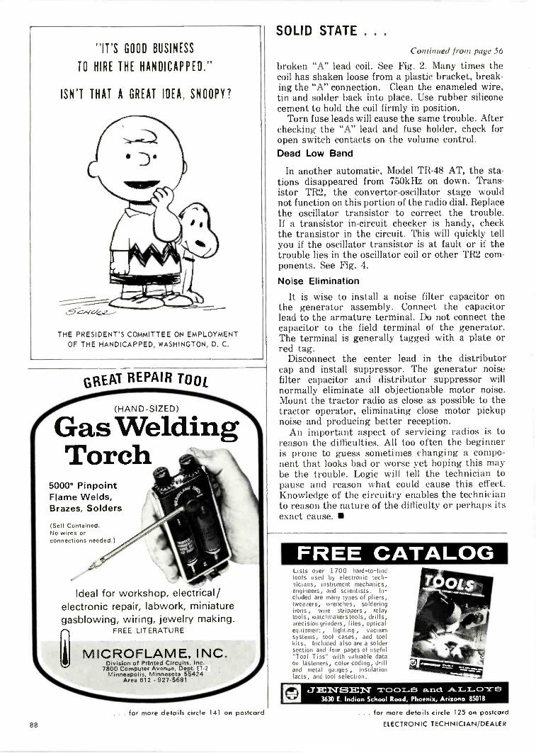
SOLID STATE . .
"IT'S GOOD BUSINESS
TO HIRE THE HANDICAPPED."
ISN'T THAT A GREAT IDEA, SNOOPY?
THE PRESIDENT'S COMMITTEE ON EMPLOYMENTOF THE HANDICAPPED, WASHINGTON, D. C.
GREAT REPAIR TOOL
(HAND -SIZED)
Gas WeldingTorch
5000° PinpointFlame Welds,Brazes, Solders
(Self Contained.No wires orconnections needed.)
Ideal for workshop, electrical/electronic repair, labwork, miniaturegasblowing, wiring, jewelry making.
FREE LITERATURE
MICROFLAME, INC.Division of Printed Circuits, Inc.
7800 Computer Avenue, Dept. ET -2Minneapolis, Minnesota 55424
Area 612 - 927-5681
Continued from page 56
broken "A" lead coil. See Fig. 2. Many times thecoil has shaken loose from a plastic bracket, break-ing the "A" connection. Clean the enameled wire,tin and solder back into place. Use rubber siliconecement to hold the coil firmly in position.
Torn fuse leads will cause the same trouble. Afterchecking the "A" lead and fuse holder, check foropen switch contacts on the volume control.Dead Low Band
In another automatic, Model TR-48 AT, the sta-tions disappeared from 750kHz on down. Trans-istor TR2, the convertor -oscillator stage wouldnot function on this portion of the radio dial. Replacethe oscillator transistor to correct the trouble.If a transistor in -circuit checker is handy, checkthe transistor in the circuit. This will quickly tellyou if the oscillator transistor is at fault or if thetrouble lies in the oscillator coil or other TR2 com-ponents. See Fig. 4.
Noise Elimination
It is wise to install a noise filter capacitor onthe generator assembly. Connect the capacitorlead to the armature terminal. Do not connect thecapacitor to the field terminal of the generator.The terminal is generally tagged with a plate orred tag.
Disconnect the center lead in the distributorcap and install suppressor. The generator noisefilter capacitor and distributor suppressor willnormally eliminate all objectionable motor noise.Mount the tractor radio as close as possible to thetractor operator, eliminating close motor pickupnoise and producing better reception.
An important aspect of servicing radios is toreason the difficulties. All too often the beginneris prone to guess sometimes changing a compo-nent that looks bad or worse yet hoping this maybe the trouble. Logic will tell the technician topause and reason what could cause this effect.Knowledge of the circuitry enables the technicianto reason the nature of the difficulty or perhaps itsexact cause.
FREE CATALOGLists over 1700 hard -to -findtools used by electronic tech-nicians, instrument mechanics,engineers, and scientists. In-cluded are many types of pliers,tweezers, wrenches, solderingirons , wire strippers , relaytools, watchmakers tools, drills,precision grinders, files, opticalequipment, lighting , vacuumsystems, tool cases, and toolkits. Included also are a soldersection and four pages of useful"Tool Tips" with valuable dataon fasteners, color coding, drilland metal gauges , insulationfacts, and tool selection.
JECNISIEN TOOLS and. ALLOYS3630 E. Indian School Rood, Phoenix, Arizona 85018
. for more details circle 141 on postcard
88
. for more details circle 125 on postcard
ELECTRONIC TECHNICIAN/DEALER

Vectorious Oscilloscope.There's a real victory in themaking of this new B&KDiagnostic Oscilloscope. We'remaking the idea of using theoscilloscope popular again. Andone of the victory signs is thatour oscilloscope is also avectorscope.
In fact, it's theonly one that locatesall vector inputsand controls on thefront panel. Whichis simply for yourconvenience.(Something forwhich oscilloscopes have notbeen noted.)
Here's another sign of victory:Our oscilloscope has anintermittent analyzer withelectronic memory and optionalaudio/visual remote alarm.A diagnostic exclusive fromB&K...
With it, the elusive intermittentconditions that make so manyTV sets tough dogs can nowbe detected and identified inyour absence. Preset one control.When the faulty stage isdetected, you'll know abcut itas soon as you come backfrom service calls. Then run thescope overnight to check anotherset for an intermittent condition.
All this adds up to greatershop efficiency, more time forprofit -making service calls and alot more mileage out of a veryfine diagnostic oscilloscope.
An oscilloscope that showsvector patterns exactly asspecified by color TVmanufacturers. And permitsreading peak -to -peak voltagesin all ranges on a double -scalecalibrated screen-just byturning a switch. (As the range isselected, the appropriate scale
lights automatically.)Automatic synchronization
locks in all patterns at anysignal level or frequency. Thereare also fewer controls and theseare positioned for easieroperation.
Give our DiagnosticOscilloscope/Vectorscope somethought. And you'll real;ze thatit's a victory for your side, too.See your B&K Distribute' ordrop us a note for detailedliterature on Model 1450 and ourfull -line test equipmentcatalog, AP -24.Model 1450, Net: $27995
B & K Division of DYNASCAN CORPORATION1801 W. Belle Plaine Chicago, Illinois 60613
Where electronic innovation is a way of life.
. . . for more details circle 107 on postcardFEBRLARY 1969 89

Dyna-flexthe only practical probefor testingtransistors in circuits.
*PatentPending
Throw away your alligator clips!Dyna-flex. the world's first andonly 3 -point probe. makes instanttest connections to transistors inprinted boards. Easy to use, theDyna-flex probes are spring -mounted on ball joints. Allow youto adjust to any spacing 1/32- to5, 8", using only one hand. Dyna-flex eliminates costly unsoldering;can be used to make temporarycomponent substitutions on printedwiring boards. Each point is color -coded for fast, easy identification.Dyna-flex-another engineeringbreakthrough from B&K.
Model FP -3. $12.95 user net
B&K Division of Dynascan Corporation1801 W. Belle Plain Avenue Chicago. Illinois 10013
Where Electronic Innovation Is A Way 01 Life
. for more details circle 108 on postcard
CATALOGS Et
BULLETINS
Speakers 400A new I6 -page full -line catalog cov-
ering the company's entire line of ori-ginal equipment and replacementspeakers is available.
The catalog presents a comprehen-sive listing of the company's entireproduct line, representing a broadrange of quality speakers for everyknown sound application.
The catalog is printed in the stan-dard 81/2 x I I in. page size. It is de-signed for convenient counter and fileuse, and should provide an invaluablesales aid and guide to all distributorsand dealers as well as an ideal ref-erence for all original equipment man-ufacturers. Oxford.
Equipment and Components 401A 132 -page 1969 catalog, the biggest
in the company's 22 -year history isintroduced. The new four-color catalogcontains thousands of electronic itemsfor the home, car and business. Thecatalog features brand name hi fi andstereo components, two-way communi-cation equipment, televisions, autotape cartridge players, closed circuitTV, intercom systems, portable radios,plus hundreds of component items.Team Electronics.
HEP Cross Reference Guide 402A new cross reference guide lists
almost 18,000 semiconductors withtheir equivalents from the widely avail-able HEP line. The HEP line, whichreportedly offers the broadest coveragein the industry, is a series of devicesfor the hobbyist, experimenter and pro-fessional serviceman. It contains 175devices that meet almost every replace-ment need and is one of the most com-plete cross references available. It listsEIA-registered IN and 2N numbers,foreign devices and many house num-bers used by both semiconductor andequipment manufacturers. The 64 -pagecross reference guide is a convenient41/4 x I I in. and is punched to fit astandard three-ring binder. It also in-cludes a table of equivalents, tips onusing replacement devices along withtheir respective outline drawings anddimensions. Motorola.
Solderless Terminal 403A colorful "wall catalog" that simpli-
fies selection of the correct style of
solderless terminal is offered. All stylesof terminals and connectors are shownin actual size including non -insulatedsingle grip, insulated single grip, insu-lated bell -mouth single grip, insulatednylon double grip and various styles ofquick connects and adaptors ranging
from 6-22 AWG. Also shown are hand -operated attaching tools for both insu-lated and non -insulated styles. Eachstyle of terminal is grouped as to wiresize and identified by catalog number.The catalog is 14 x 18in. in size and isprinted in full color for life -like pre-sentation. It is mounted on heavy card-board and varnished to withstandsoiling. There are two holes at the topof the card so it can be hung withstandard pegboard hooks. Vaco.
Recording Basics 404A 24 -page guidebook for more effec-
tive use and better understanding ofmagnetic recording tape is offered.Called "Recording Basics," the bookcontains information on such subjectsas the construction and manufacture ofrecording tape, how to select the righttape for individual requirements andhow to figure recording time for themany different tapes. The book alsocontains a basic explanation of thevarious recording formats. Illustrativediagrams assist in the explanation ofsuch terms as full -track, dual -track andfour -track recording. The new book al-so contains helpful information on suchsubjects as splicing, editing, the use ofleader and timing tape, recorder main-tenance and the care and handling ofmagnetic recording tape. 3M.
Sound Column 405A new sound column booklet is
available which features a selectionguide making it possible to solve the"which columns?" problem accuratelyand confidently in 90% of all poten-tial installation situations. It also de -
90 ELECTRONIC TECHNICIAN/DEALER

Doesn't think of himself as thereckless type at all. But he goeson taking the big risk. Clings toa habit which causes 100 deathsevery day from lung cancer andwhich contributes to many, manymore from coronary artery andrespiratory diseases. Studies showthat the death rate from lung can-cer alone for cigarette smokers(one -pack -a -day or more) is 10times higher than for nonsmokers.
Nobody says it's easy to stop.But living that dangerously oftenwinds up in not living at all.
american cancer societyTHIS SPACE CONTRIBUTED BY THE PUBLISHER
CRT Rebuilder
Rebuild your own CRT's. Averagecost B/W $1.50-Color $8.50. Easyto operate. Requires only 4x8 feet ofspace.Supplies for your first 50 picture tubesfree!Color - black and white. Rebuilt whileyou are here. See the results for yourself.
Terms Available
Lakeside Industries - Div. Associated Ind.6338 N. Clark St.Chicago, III. 60640Phone: 312-465.2881
Free demonstration appointment Send me more information
Name
AddressCity State
1
CATALOGS a
BULLETINS
scribes in clear language the theory ofsound columns and provides many in-stallation tips and application ideas.
Other new literature includes newcatalogs of high fidelity and soundsystem equipment, special sheets forarchitectural use, accordion type fold-ers for mailing use on sound columns,"decor/oriented" high fidelity equip-ment and speech director portable PAsystems. Argos.
Phono Cartridges andHi Fi Components 406
An eight -page catalog coveringphono cartridges as well as other highfidelity stereo cartridges, tone arms,styli and headphone amplifiers is avail-able. Complete specifications and per-formance information, along withcharts and definitions of trackability(the newest method of gauging totalperformance of cartridges) is provided.The new publication covers the com-plete cartridge line, including the V- 15Type 11 "Super -Track" cartridge.
Application data and prices are alsogiven. Shure.
Communications Equipment 407A 98 -page catalog No. 1068 relating
to wire, cable, CCTV, CATV, ETVhardware and miscellaneous lines ofequipment necessary to the communi-cations industry is published. A newlyintroduced series of Futura amplifierscovering both 12 and 21 Plus channelcapability, including trunk line amplifiermodules, bridger modules, power sup-ply modules and AGC modules is in-cluded. Vikoa.
Sound Products 408An all -new high fidelity sound prod-
ucts catalog, No. I65 -P is now avail-able. Illustrated in color, catalog showsnew speakers in highly styled furnituresystems designed to complement anyroom decor-and all provide completeand distortion -free reproduction ofthe sound spectrum. Also illustratedand described is the line of coaxialand triaxial speakers plus the com-plete series of high fidelity componentspeakers and accessories. Jensen.
Soldering Tools 409Newly expanded, comprehensive lit-
erature details vary and benefits oftemperature -controlled production sol-dering tools. A complete catalogingof these tools and a broad looseningof selectable temperature sensing testsare included. The line of tools is suit-able for most industrial electronicssoldering application. Weller.
Sinnrecord wearcy'
IAN I PHONOGRAPH NEWS
AND CARTIIDGES
Put this E -V
needle/cartridgedisplay next toYour cash register... it insuresgood fortune!
Put this handsome merchandiserwith its stock of E -V literatureon your counter. You've just takenthe first step toward bigger phononeedle & cartridge sales.
Now, take the secondstep. Let your E -V distri-butor help you fill it withthe best-selling needles &cartridges in town.
Best-selling because the Electro-Voice computer prepares accurate,up-to-date popularity lists foryour guidance. Easy -selling becauseall E -V needles and cartridgesmeet or exceed original equipmentspecifications for quality.
Your Electro-Voice distributorhas the broadest line of exact-replacement phono parts in thebusiness. Needles, cartridges, wheelsand belts. Plus a merchandiserdeal that helps you sell them.Start your good fortune today atyour nearby E -V distributor's!
ELECTRO-VOICE, INC., Dept. 297T663 Cecil St., Buchanan, Michigan 49107
gkere akaA SUBSIDIARY Of GULION INDUSTRIES, IN('
. . . for more details circle 129 on postcardFEBRUARY 1969
91

MAKEYOUROWN
TUNER TEST!If you're like most professional TV tech-
nicians, you clean the tuner of every chassis youservice.
But how careful are you in choosing your tunerspray? The wrong spray can cost you a lot Inaggravation and callbacks.
That's why we ask you to
MAKE THIS TEST YOURSELF1. Tune in a good color picture on any color set.2. Spray the tuner with anything but a Chem-
tronics Spray.3. You will see the color tads and disappear al-
most Immediately, due to the changes ofcapacitance In tuned circuits caused by thespray.
NORMAL RESPONSE RESPONSE DETUNEDBY SPRAY
4. Walt about 10 minutes for the spray to dry.Unfortunately, the color will not come back.
5. Spray the tuner with Chemtronics TUN -O -WASH.B. Wait about two minutes and color will be re-
stored.
WHAT THIS TEST MEANS TO YOUMost tuner sprays leave a residue of slow dry-
ing, petroleum base lubricant. This saturates thecoils and other components causing a shift Inresponse as shown in Illustration.
To compensate for this shift, you often adjustoscillator slugs. Then, when the set has playedin your customer's house for a week or two, theresidue dries out, shifting the oscillator backtoward its original frequency. If the customercan't compensate for this drift with the finetuner, you have a callback on your hands. Evenif the drift is not too severe, the remaining resi-due picks up dirt and eventually "gunks up"the tuner.
TUN -O -WASH IS LIKE NO OTHERSPRAY ON THE MARKET
TUP,10WASH is a powerful, high pressure spraydesigned to do just one job superlatively well.It melts away grease, oil, dirt and corrosionquickly and completely. It leaves absolutely noresidue behind. Tests show that TUN -O -WASH isat least 10 times as effective as any other tunerspray in degreasing gunked up tuners.
Use TUN -O -WASH as your first step in repair-ing any tuner. It gives you a clean start in muchthe same way as the ultrasonic bath used bytuner specialists - but without harmful vibra-tion. You'll be surprised at howmany tuners you can repair theTUN -0 -WASH way.
Then, once the tuner Is restoredto good working condition, you canlubricate It with a light spray ofChemtronics famous COLOR-LUBE,guaranteed not to detune, attackplastic parts or "gunk up." COLORLUBE uses a unique synthetic lu-bricating formula developed specifically for color TV tuners,
Giant 24 oz. canonly ;3.25 dealer net.
1260 RALPH AVENUE BROOKLYN, N.Y. 11236
. . for more details circle 1 1 1 on postcard
92
AD INDEX
Accurate Instrument Co. 81
82
Argos Products Co 77
Arrow Fastener Co 72
B & K Div., DynascanCorp. 25, 28, 89, 90
Belden Corp. 26-27Bell PEA Products Corp. 86
Chemtronics, Inc. 92
Chrysler Corp., Dodge Div. 85
Cleveland Institute ofElectronics 69
Eico ElectronicInstruments Co.
Electro-Voice, IncELECTRONIC TECHNICIAN
Book Club 34, 37, 64Finney Co. 33GC Electronics Co. 22
Gem City Tuner Service 24General Electric, Tubes Div 63, 83Greyhound Lines, Inc 87
Heath Co 32
Hudson Lamp Co. 38
Injectorall Electronics Corp 69
International Textbook Co 23
Jensen Tools & Alloys 88
Jerrold Electronics Corp 3rd CoverJFD Electronics Corp. 74
E. F. Johnson Co. 67
Lakeside Industries 91
Lampkin Laboratories 92
Leader Instruments Corp 86
Lectrotech, Inc 79
Loral Distributor Products 40Mercury Electronics Corp 73
Michigan Magnetics 72
J. W. Miller Co. 74
Mosley Electronics Corp 80
Motorola HEP Corp. 71
National Radio Institute,Conar Div. 80
Newcomb Audio Products 82
Precision Tuner Service 29
Printed Circuits, Inc.,Microflame 88
Quietrole Co 72
Radio Corp. of America 4th CoverRCA Institutes 31
RCA Test Equipment 39Sencore 75, 76S & A Electronics Corp. 92
Sylvania Electric Products 65
Triplett Electrical Instrument Co 84Tuner Service Corp. 19
Weller Electric Corp 78Xcelite, Inc. 24Zenith Sales Corp. 20
Aerovox Co
2nd Cover91
WAVE FORM ANALYSIS& PEAK FM MODULATION
all for LESS MONEY!The Lampkin 205A FM Modulation Meteraccurately indicates PEAK modulation onmobile transmitters. To shoot troublevisually, use your own general-purposeoscilloscope at the 205A rear jack out-put. This makes a low-cost, highly effec-tive test combo - and a well-roundedshop - all for less money.
Lampkin pioneered the PEAK voltmeterfor FM modulation indication.
Like to see the complete specs? Mailcoupon today!
Use this coupon for FREE booklet "HowTo Make Money in Mobile -Radio Main-tenance" and information on Lampkinmeters.
Name
AddressCity State Zip_LAMPKIN LABORATORIES, INC.
Div. II , Bradenton, Fla. 33505
ELIMINATE CALL-BACKS
.
RevolutionaryMODEL UPW
UHF PASSIVE WAVE ANTENNAThis system in which there are noelectrical connections,
PROVIDES HIGH GAIN ACROSS THEENTIRE UHF BAND
and eliminates noise caused by looseelements at high frequencies. Highoverall gain across the entire UHFband makes this antenna more desir-able than any frequency consciousyogi types being marketed today. Ex-cellent color reception assured. Moregain than a Parabolic. Top qualityconstruction.
Write for literature and lowretail prices. All
inquirie.v given prompt attention.
S & A ELECTRONICS INC.Manufacturers of the TARGET ANTENNA204 W. Florence St., Toledo, Ohio 43605
Phone 419-693-0528
for more details circle 145 on postcard
ELECTRONIC TECHNICIAN/DEALER

Meet the snappiest300 -ohmconvertible aroundThe New Jerrold Paralog 300 Plus Antenna. Developedfrom and incorporating the finest features of the famousParalog Plus series. And where conditions require thesuperior performance of a Coloraxial 75 -ohm installationthe change can be made in a snap . .. with a snap -ontransformer. The results are superb. Sharp directivity eliminates color ghosts Flat response (±1 dB per channel) for optimum
color fidelity Exclusive bi-modal director system for extra gain Compact parasitic array permits quick installationParalog 300 Plus snaps together in short order and staystogether.
New snap -on transformer (optional) converts Paralog 300Plus to 75 -ohm Coloraxial performance.
Combines low loss and unexcelled impedance match with
Home preamplifiers Home DistributionSystems
quick, easy installation. Just snap it onthe boom, push into contact with leadbolts, and screw down. New weather-proof connector... no cable fittingneeded. Simply strip the cable, pushinto the transformer, and tighten.
Paralog 300 Plus comes in 7 VIP models,for metropolitan to deep fringe areas, withlist prices ranging from $15.95 to $79.95.
So pull in more profits with the VHFantenna that packs the most pull around.In signal reception. In customer recep-tion. The Jerrold Paralog 300 Plus An-tenna. See your Jerrold Distributortoday or write Jerrold Electronics Corpo-ration, Distributor Sales Division, P.O.Box A, Philadelphia, Pa. 19105.
MATV Systems Focusing on one thing...better reception
a GENERAL INSTRUMENT company. . . for more details circle 126 on postcard

Identify with RCA'sNew Look!
Meleelee.
ElectronTubes
TV-Radio Service
Dealer Nan.f.----
6
ReliReceiving TubesPicture Tubes
ILLUMINATED CLOCK(1A1428A)Trimmed in gleamingbrass, this good looking131/4" x 181/4" clock withRCA's new look will be areal asset to your store.
NEW ILLUMINATED 3' x 5' OUTDOORSIGN (1A1775)In double or single faceversions this new sign isan excellent way to combineyour service message with thegreat new look of RCA.
SET OF RCA TRADEMARK DECALS (1A1776)Eye catching decals to put in windows, on wallsor caddies, give you professional RCA productidentification.
MINI -SERVICE TOOL KIT (1A1767)Basic collection of 12 small tools especially selected toservice miniaturized circuits a great help in servicingtransistorized equipment.
RCA
COLOR TV SERVICE BANNER(1A1780)Draw immediate attention toyour color TV servicemessage with this striking,24" x 34" white satin banner.
RCnRCA Receiving Tidiesaid Mauve Tubes
ExpertColor TV Service
Your identification with RCA, theindustry leader, is strengthenedand reaffirmed with the bold newRCA trademark that says you aretoday's technician with today'sskills and a clear eye ontomorrow's electronic serviceopportunities.Additional New Look aids include"Free tube testing" decals, door-knob hangers, ad mats, pocketprotectors, Corningware cookwareand a consumer good will premiumfeaturing Cantrece stockings.RCA Electronic Components,Harrison, N. J.
ALL ITEMS ARE AVAILABLE WITHYOUR PURCHASES OF RCARECEIVING TUBES AND PICTURETUBES FROM YOUR LOCALPARTICIPATING RCA TUBEDISTRIBUTOR. CALL HIM TODAYFOR COMPLETE INFORMATION.