semi-auto mobile pallet strapping machine for vertical...
TRANSCRIPT
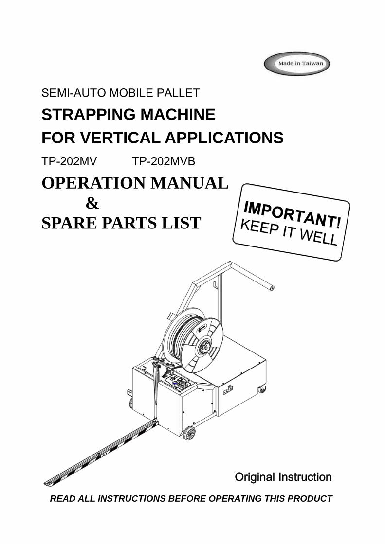
SEMI-AUTO MOBILE PALLET
STRAPPING MACHINE FOR VERTICAL APPLICATIONS TP-202MV TP-202MVB
OPERATION MANUAL &
SPARE PARTS LIST
Original Instruction
READ ALL INSTRUCTIONS BEFORE OPERATING THIS PRODUCT
PART I
CONTENTS
1. Safety Instructions ............................................................................ 1
2. Construction and Units ...................................................................... 3
3. General Safety Remarks .................................................................... 5
4. Machine Information ......................................................................... 7
5. Operating the Machine ...................................................................... 20
6. Adjustment ........................................................................................ 22
7. Maintenance ...................................................................................... 23
8. Troubleshooting Guide .................................................................…28
9. Wiring Diagram ............................................................................…30
- 1 -
1. Safety Instructions
THIS MANUAL GIVES YOU INFORMATION ON SAFETY INSTRUCTIONS, SPECIFICATIONS, OPERATION AND MAINTENANCE OF STRAPPING MACHINES. BEFORE OPERATING OR SERVICING THE MACHINE, PLEASE REVIEW THE ENTIRE MANUAL AND FOLLOW THE SAFETY INSTRUCTIONS CAREFULLY.
(1) Before Operating
a. Verify that the power line voltage is correct. b. The machine must be properly grounded to avoid a shock hazard. All wiring must be in
accordance with local wiring standards. c. The strapping machine can only be operated with polypropylene (P.P.) strapping; do not
use polyester (PET) strapping or polyethylene (PE) cord strap.
(2) During Operation a. The height of the package should not be less than 280mm (11.06"). b. Check if the machine emits any smokes or unusual sound when it is running.
(3) After operating a. Remove dust and dirt from the unit. b. Turn off the power when the machine is not in use.
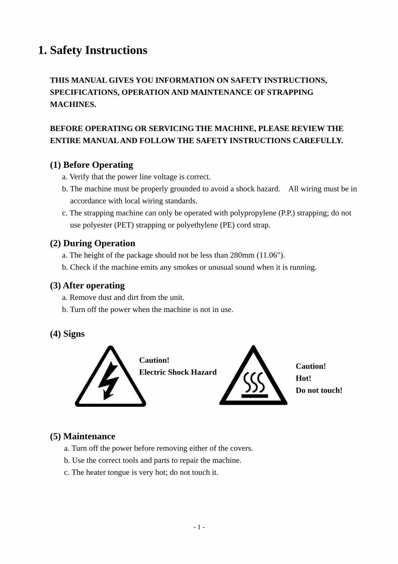
(4) Signs
(5) Maintenance a. Turn off the power before removing either of the covers. b. Use the correct tools and parts to repair the machine. c. The heater tongue is very hot; do not touch it.
Caution! Electric Shock Hazard
Caution! Hot! Do not touch!
- 2 -
(6) Storage a. The store room must be dry. b. Do not expose the machine to extreme cold or heat environment. c. Place the machine on an even floor in order to avoid any distortion.
(7) Other Reminders a. Do not alter or bypass protective interlocks. b. An operation manual must remain attached to the machine at all times. c. Do not alter the equipment or circuitry unless authorized to do so by the manufacturer. d. Do not operate the machine with the covers removed. e. Never put any part of your body near, under or into a moving machine. f. Do not overload the machine by exceeding the performance limitations specified in this
manual.
- 3 -
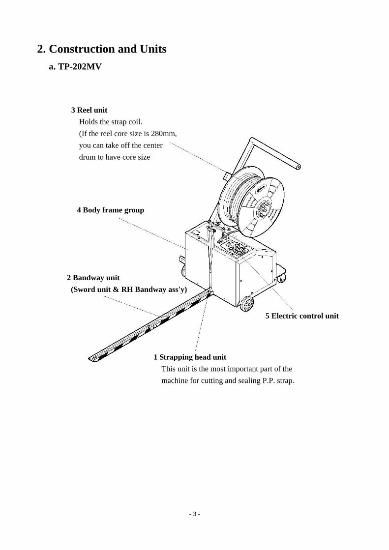
2. Construction and Units a. TP-202MV
3 Reel unit Holds the strap coil. (If the reel core size is 280mm, you can take off the center drum to have core size
4 Body frame group
2 Bandway unit (Sword unit & RH Bandway ass'y)
5 Electric control unit
1 Strapping head unit This unit is the most important part of the machine for cutting and sealing P.P. strap.
- 4 -
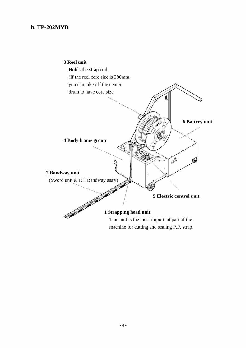
b. TP-202MVB
3 Reel unit Holds the strap coil. (If the reel core size is 280mm, you can take off the center drum to have core size
4 Body frame group
2 Bandway unit (Sword unit & RH Bandway ass'y)
1 Strapping head unit This unit is the most important part of the machine for cutting and sealing P.P. strap.
5 Electric control unit
6 Battery unit
- 5 -
3. General Safety Remarks (1) Basic Operation
The manual and the safety remarks are to be read before use. The operation manual should be kept with the machine at all times for regular maintenance and inspections.
This machine was built with state of the art technology and rigid adherence to safety standards.
Unless used properly, it can cause injury to operators or persons in close proximity to the machine. In addition, improper use can cause damage to the machine or property around the machine.
(2) Basic Safety Precautions The user is to be instructed in all other generally applicable legal and other mandatory regulations relevant to accident prevention and environmental protection in addition to the operating instructions.
For safety reasons, long hair must be tied back or otherwise secured, garments must be close fitting and no jewelry may be worn.
Use protective equipment whenever required by circumstances or by law.
Carefully observe all safety instructions and warnings attached to the machine and make sure that they are always complete and perfectly legible.
Always make certain that persons being trained and instructed in working on or with the machine are permanently supervised by an experienced person.
Work on the electrical system and equipment of the machine is only to be carried out by a skilled electrician or by persons under the supervision and guidance of a skilled electrician and in accordance with the rules and regulations of electrical engineering.
(3) Safety Instructions Governing Specific Operational Phases Avoid any operation mode that might be unsafe.
All necessary precautions to ensure that the machine is only used being in a safe and reliable state are to be taken. The machine is only to be operated if all protective and safety devices, including removable safety devices, emergency shut-off equipment, noise-protection elements and exhaust systems are in right place and fully functional.
The machine is to be checked for damage and defects at least once per work shift. Any changes including the working behavior of the machine are to be reported to competent persons immediately. If necessary, the machine is to be stopped and locked immediately.
- 6 -
In case of any malfunction the machine must be stopped and locked until the defect has been eliminated.
Generally make sure that nobody is at risk before starting up the machine. All personnel that will be operating this machine should be thoroughly trained in all phases of operation and safety.
Always tighten unscrewed connections after maintenance and repair.
After completing maintenance and repair, all safety devices removed for setting up or repairing the machine must be reinstalled and checked for functionality prior to putting the machine back into service.
To minimize the environmental impact, all consumables and replaced parts must be disposed of safely.
Before starting the machine, check that the accessories have been stowed away safely.
Do not attempt any operation that may be a risk to the stability of the machine.
(4) Warning of Electrical Dangers Immediately remove power to the machine in case of trouble in the electrical system. Replace a fuse with one with the same style and ratings; pay particular attention to matching the specified current.
Any electrical work performed on the equipment must be conducted by a skilled electrician or under the supervision of a skilled electrician. All work must be observed good electrical engineering practice and follow safety rules and local wiring standards.
Inspect the electrical equipment of the machine at regular intervals. Tighten any loose connections. Check wiring for scorch marks; replace scorched wiring and determine and correct the reason for the overheating.
When working on live equipment, ensure that a second person is available to cut power in case of an emergency. When appropriate, secure the working area with safety tape and a warning sign. Use insulated tools for electrical work.
Before working on high-voltage assemblies, turn off the power supply. Carefully discharge the supply cable and short-circuit any energy-storage components such as capacitors.
If the equipment was moved, carefully refit and refasten all parts removed for transport before reapplying power.
Before moving the machine, remember to disconnect the power cable.
- 7 -
(5) Grounding Instructions Shall Include the Following: This product must be grounded. In the event of an electrical short circuit, grounding reduces the risk of electric shock. This product is equipped with a cord that has a grounding wire and an appropriate grounding plug. The plug must be plugged into an outlet that is properly installed and grounded in accordance with all local codes and ordinances.
If repair or replacement of the cord or plug is necessary, connect the ground wire to the ground terminal of the plug. The wire with green insulation (with or without yellow stripes) is the grounding wire.
Check with a qualified electrician or service person if the grounding instructions are not clear or if in doubt about the proper grounding of the machine. Do not modify the plug provided; if it will not fit the power outlet, have the proper outlet installed by a qualified electrician.
This product is designed for use on a nominal 120 (230) volt AC circuit and has a grounding plug.
DANGER! Improper installation of the grounding can result in electrocution.
4. Machine Information (1) Areas of Application and Machine Description
This plastic strapping machine can be used for a wide range of applications where the minimum package height is at least 280mm. This machine is particularly suitable for vertical low volume pallet strapping applications.
Machine Description Semi-automatic plastic strapping machine for use with polypropylene strapping. Heavy duty construction. Simple, safe and user-friendly operation. With light weight and compact size, it is easy to move beside the pallet you want to strap. Handle is with feeding switch to feed the strap to the required length.
Environment Information
The strapping machine shall be installed in the following conditions: Supply voltage: 0.9 - 1.1 nominal supply voltage Source frequency: 0.99 - 1.01 nominal frequency Ambient temperature: 5°C - 40°C (41℉-104℉). Relative humidity: not exceed 50% at 40°C. Please provide a suitable illumination around the machine for safety operation.
- 8 -
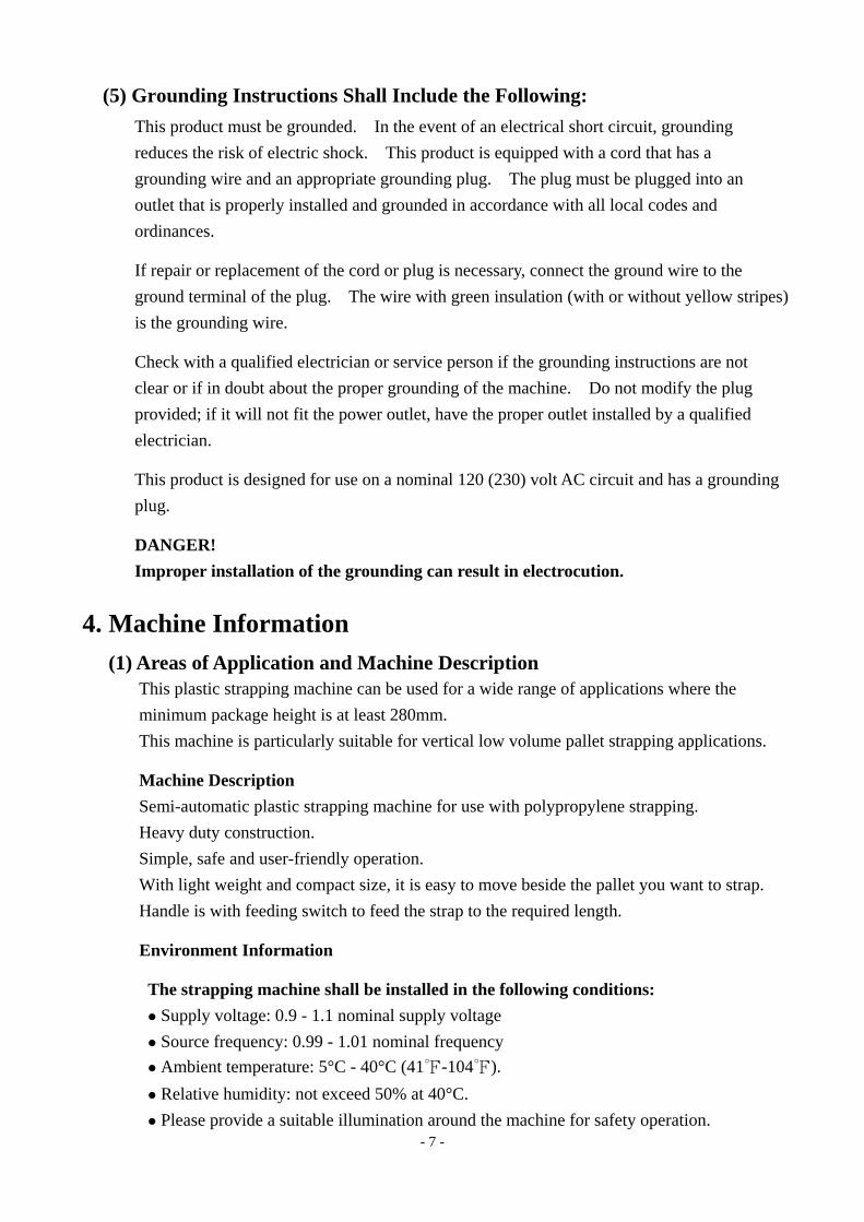
(2) The Safety Devices
This machine must only be operated with polypropylene strapping. The use of other synthetic straps may produce hazardous substances to health.
Caution! Power Switch (QS1). This switch is lockable for safety. Danger of burns near the heating unit! (1) Dangerous points in the machine are covered by the screwed table top. For safety reason, please take off the Sword Unit and put it by the machine body when the machine is not operated, that is to prevent the people hitting or stepping the Sword Unit and will make the Sword Unit damage. For safety reason, make sure the Sword Unit do not be hit or crushed when moving the machine.
(3) Electrical Specifications
System configuration: 1L+N+PE (Ground) 1L+N+PE (Ground) Nominal power: 0.5 KW 0.5 KW Rated current: 7A 10A Rated voltage: 220V/230V/240V 110V Rated frequency: 50Hz 60Hz Type of current: AC - single phase AC - single phase
- 9 -
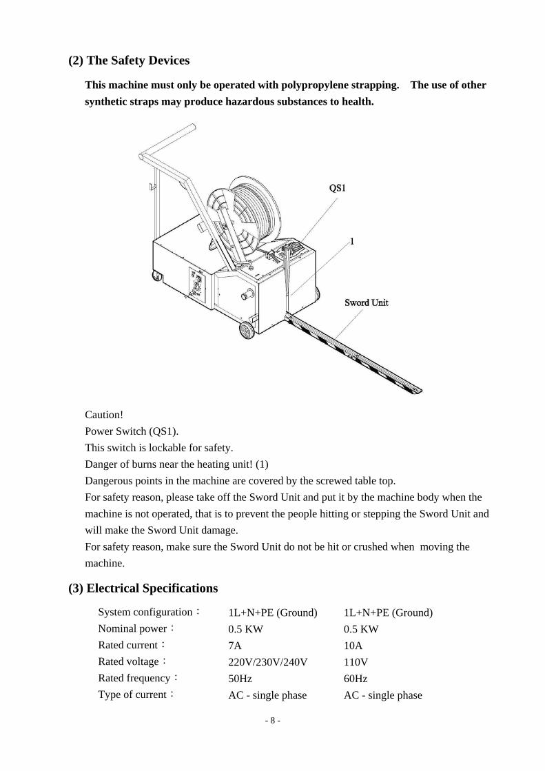
(4) Technical Data
a. TP-202MV
Sealing method Heat Strap width : 9 mm to 15.5 mm (3/8" to 5/8") Strap reel diameter : 200 mm (8") Strap reel diameter(OPTION) : 280 mm (11") Width : 696 mm (27.4") Depth : 2035 mm (80.1") Electrical Requirement : AC 110V/220V/230V/240V
(50/60Hz), 1PH Weight : 85 kg (187 lbs.) Noise emission : 78dB (A) Ambient temp : 5℃~40℃(41℉~104℉)
- 10 -
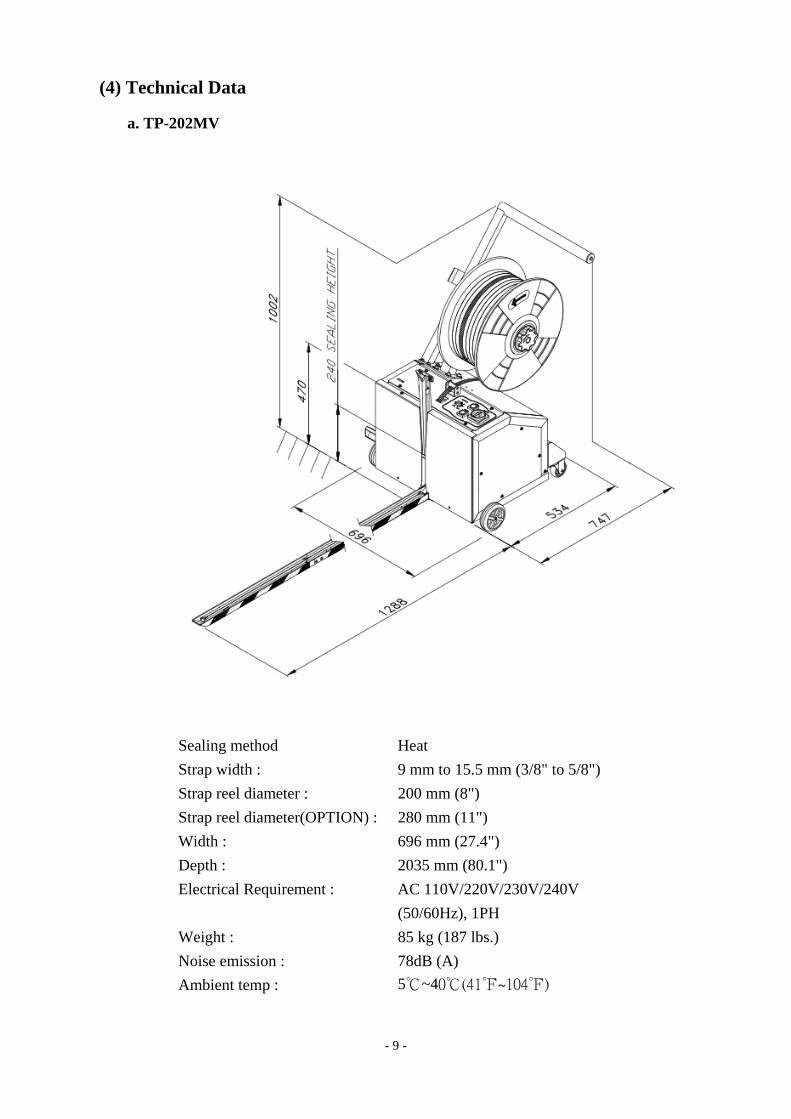
b. TP-202MVB
Sealing method Heat Strap width : 9 mm to 15.5 mm (3/8" to 5/8") Strap reel diameter : 200 mm (8") Strap reel diameter(OPTION) : 280 mm (11") Width : 696 mm (27.4") Depth : 2459 mm (96.8") Electrical Requirement : AC 110V/220V/230V/240V (50/60Hz), 1PH Weight : 183 kg (403 lbs.) Noise emission : 78dB (A) Ambient temp : 5℃~40℃(41℉~104℉)
- 11 -
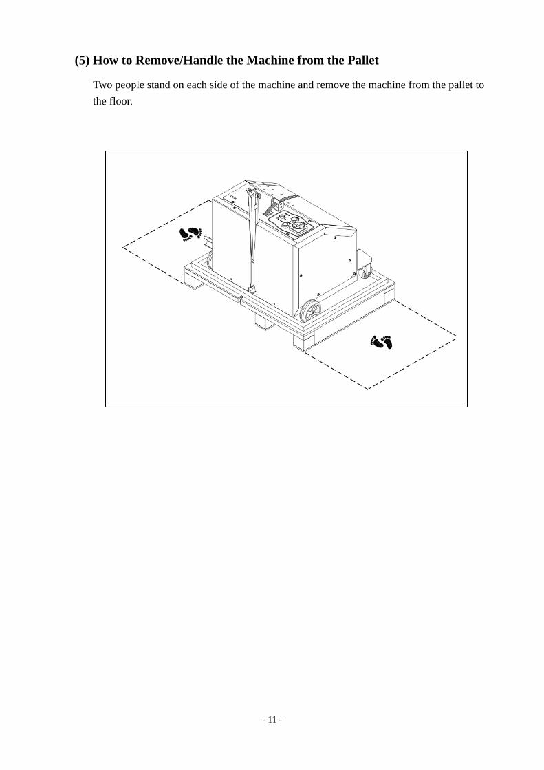
(5) How to Remove/Handle the Machine from the Pallet
Two people stand on each side of the machine and remove the machine from the pallet to the floor.
- 12 -
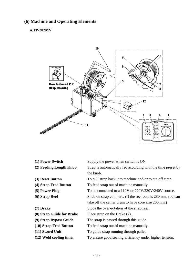
(6) Machine and Operating Elements a.TP-202MV
(1) Power Switch Supply the power when switch is ON. (2) Feeding Length Knob Strap is automatically fed according with the time preset by
the knob. (3) Reset Button To pull strap back into machine and/or to cut off strap. (4) Strap Feed Button To feed strap out of machine manually. (5) Power Plug To be connected to a 110V or 220V/230V/240V source. (6) Strap Reel Slide on strap coil here. (If the reel core is 280mm, you can
take off the center drum to have core size 200mm.) (7) Brake Stops the over-rotation of the strap reel. (8) Strap Guide for Brake Place strap on the Brake (7). (9) Strap Bypass Guide The strap is passed through this guide. (10) Strap Feed Button To feed strap out of machine manually. (11) Sword Unit To guide strap running through pallet. (12) Weld cooling timer To ensure good sealing efficiency under higher tension.
- 13 -
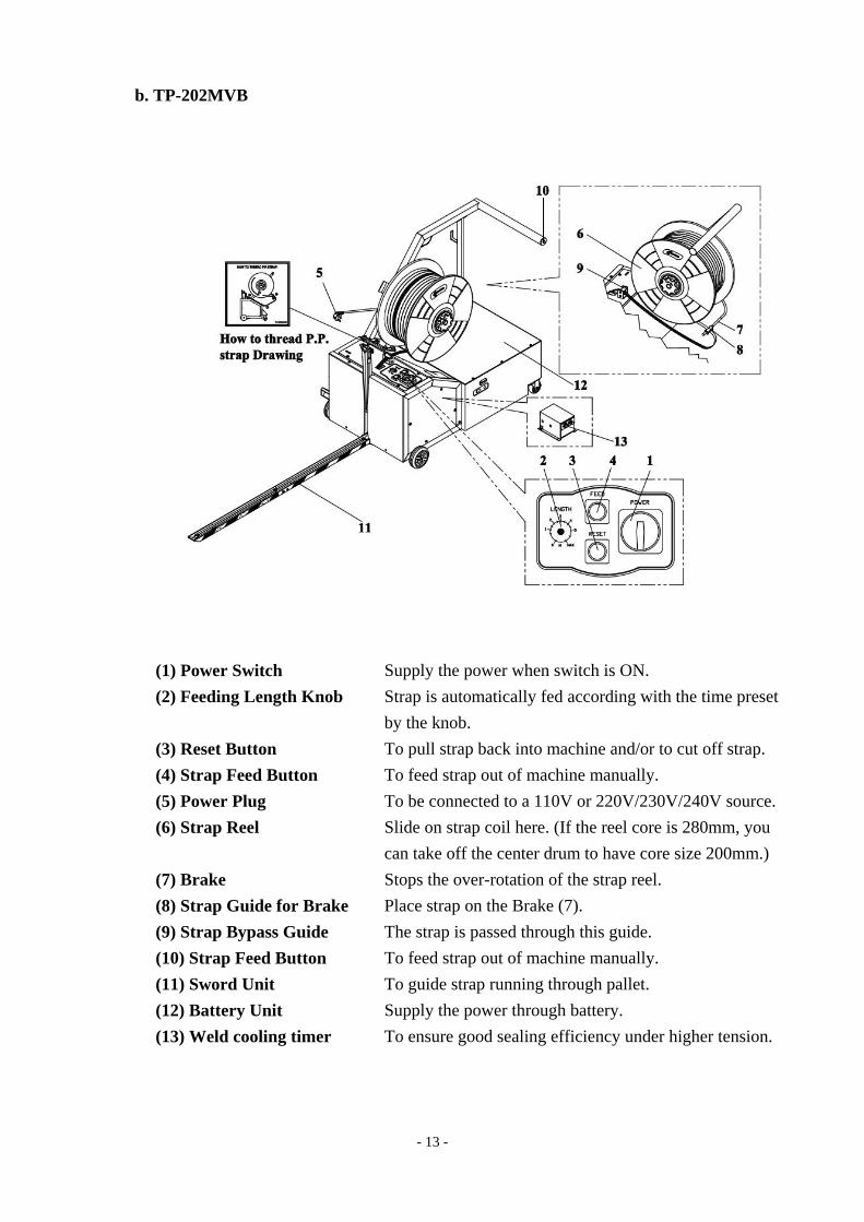
b. TP-202MVB
(1) Power Switch Supply the power when switch is ON. (2) Feeding Length Knob Strap is automatically fed according with the time preset
by the knob. (3) Reset Button To pull strap back into machine and/or to cut off strap. (4) Strap Feed Button To feed strap out of machine manually. (5) Power Plug To be connected to a 110V or 220V/230V/240V source. (6) Strap Reel Slide on strap coil here. (If the reel core is 280mm, you
can take off the center drum to have core size 200mm.) (7) Brake Stops the over-rotation of the strap reel. (8) Strap Guide for Brake Place strap on the Brake (7). (9) Strap Bypass Guide The strap is passed through this guide. (10) Strap Feed Button To feed strap out of machine manually. (11) Sword Unit To guide strap running through pallet. (12) Battery Unit Supply the power through battery. (13) Weld cooling timer To ensure good sealing efficiency under higher tension.
- 14 -
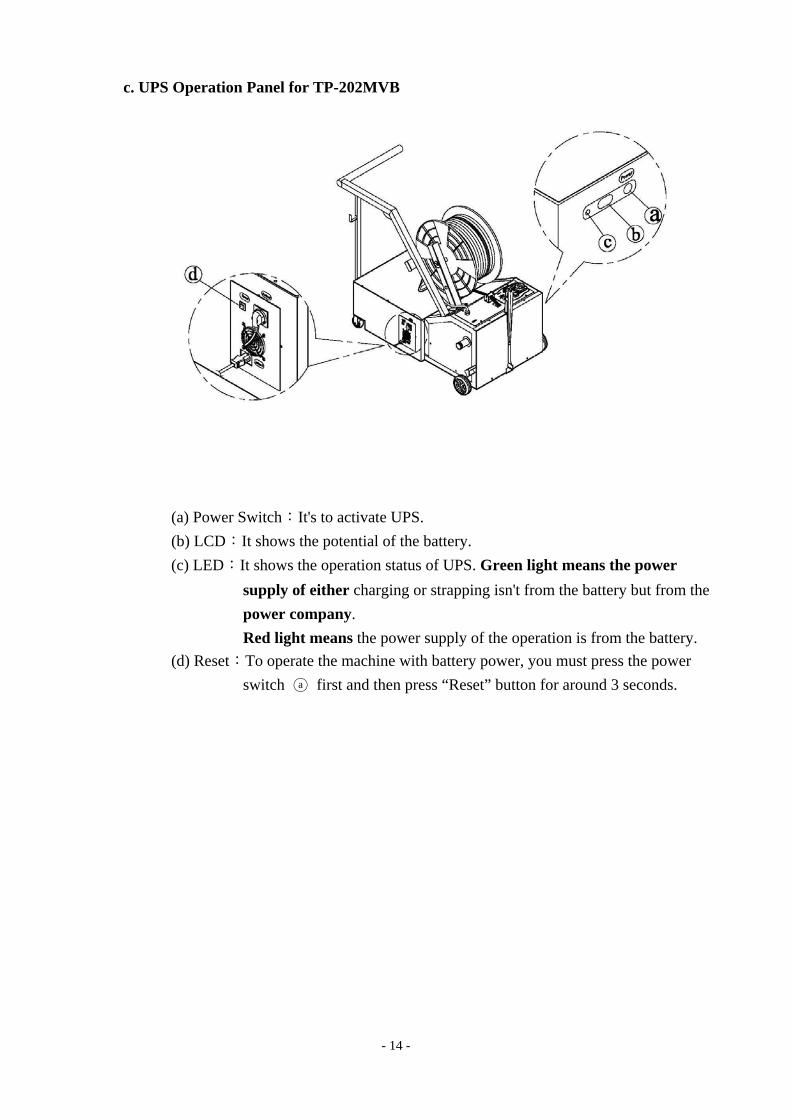
c. UPS Operation Panel for TP-202MVB
(a) Power Switch:It's to activate UPS. (b) LCD:It shows the potential of the battery. (c) LED:It shows the operation status of UPS. Green light means the power
supply of either charging or strapping isn't from the battery but from the power company. Red light means the power supply of the operation is from the battery.
(d) Reset:To operate the machine with battery power, you must press the power switch ○a first and then press “Reset” button for around 3 seconds.
- 15 -
(7) installation
a. TP-201MV
(a) Installation of Pushing Bar
○1 Please connect the wiring plug of the pushing bar to the terminal of machine. Please refer to the illustration.
○2 Put the pushing bar to the 4 M6 screw holes and then hand tighten the 4 sets of bolts (HBS0616, SW06 & PW06A)
○3 Put the pushing bar support under the pushing bar and lock it onto pushing bar with 2 sets of M8 bolts and washers.
- 16 -
○4 Also tighten the pushing bar support to the frame with 2 sets of M8 bolts and washers.
○5 Tighten the 4 sets of M6 bolts and washers that you just hand tighten on the step 2.
○6 After fixing the pushing bar, fasten the power cord with cable clamps and screws TMS0408 on the pushing bar.
- 17 -
(b) Sword Assembling
Lock Bandway Ass'y (LH) ○1 and Bandway Ass'y (RH) ○2 in place by FMS0610 ○3 .
(c) Install the sword to the machine body Fit the sword into the Block ○4 at the bottom of the machine until the sword is locked in place. Make sure that the sword is hitched in with the hook ○5 .
- 18 -
b. TP-201MVB
(a) Installation of Pushing Bar
○1 Please connect the wiring plug of the pushing bar to the terminal of machine. Please refer to the illustration.
○2 Put the pushing bar to the 4 M6 Screw holes and then hand tighten the 4 sets of bolts and washers.
○3 Put the support bar under the pushing bar and lock it onto pushing bar with 2 sets of M6 bolts and washers.
○4 Also tighten the support bar to the battery frame with 2 sets of M6 bolts and washers. ○5 Tighten the 4 sets of M6 bolts and washers that you just hand tighten on the
step ○2 .
pushing bar
pushing bar
support bar
pushing bar
support bar
- 19 -
○6 After fixing the pushing bar, fasten the power cord with cable clamps and screws TMS0408 on the pushing bar.
(b) Sword Assembling
Lock Bandway Ass'y (LH) ○1 and Bandway Ass'y (RH) ○2 in place by FMS0610 ○3 .
(c) Install the sword to the machine body
Fit the sword into the Block ○4 at the bottom of the machine until the sword is locked in place. Make sure that the sword is hitched in with the hook ○5 .
(d) Plug the connector from battery to UPS
1. Loosen the screws of Battery Cover ○1 and remove it. 2. Plug the Battery Wire ○2 to the housing ○3 of UPS. 3. Put Battery cover ○1 back and fix it with screws.
1
3
2
pushing bar

- 20 -
5. Operating the Machine (1) How to Load P.P Strap
Please make sure the power is off before you load the strap in the reel.
Step 1 Please pay attention to the direction mark on the Outer Flange ○2 . Put a coil of strap into the Inner Flange ○1 according to the direction mark. Then install the Outer Flange ○2 and tighten the reel nut handle ○3 . (refer to following drawing A)
Step 2 Pull out some strap to thread it through the roller ○4 on the Break Arm as well as two rollers ○5 . Then bend the strap a little to let strap tip can be fed smoothly into roller ○6 about 10cm or longer. (refer to following drawing B)
Step 3 Turn on the power switch.
- 21 -
(2) How to Operate
a. TP-202MV
1. Turn main switch QS1 to ON. The heating element will reach the working temperature at approximately 2 minute.
2. Push the machine to let the sword unit pass through to the pallet. Have the front plate of the machine close to the package.
3. Pull up the strap end around the package and insert the tip of the strap into the strap inlet to activate the strapping cycle. Then, the strapping cycle is completed.
4. Move the machine away from the package. Be sure the whole sword unit is totally out of the package.
b. TP-202MVB
1. Press the Power Switch of UPS ○a . 2. When operate the machine with only battery power, press the Reset button ○d on the
UPS for around 3 seconds until the battery starts to supply the power(LED turns red). 3. Turn main switch QS1 to ON. The heating element will reach the working
temperature in approximately 2 minutes. 4. Push the machine to let the sword unit pass through to the pallet. Have the front
plate of the machine close to the package. 5. Pull up the strap end around the package and insert the tip of the strap into the strap
inlet to activate the strapping cycle. Then , the strapping cycle is completed. 6. Move the machine away from the package. Be sure the whole sword unit is totally
out of the package. 7. After operation, please turn off switch QS1 before turning off UPS.
QS1
- 22 -
6. Adjustment
(1) Strap Width
Adjustment for strap in different width can be done with screw driver and wrench. The adjustment must be made in Three places, Fig.A. Fig.B. Fig.C. as shown below. For A, the width of band guide should be at 12.5mm when using 9mm and 12mm, strap and the width of band guide should be at 15.5mm when using 15mm strap. For B, when you install the RH Bandway ass'y, you need to adjust the position of two nuts in Fig. B to set the RH Bandway ass'y on the good position. (Center of down layer Strap) and adjust the height of RH Bandway ass'y about 1.5mm lower then slide table. (Fig .C)
When you change the strap width you need to change the parts as show in follow detail:
- 23 -
(2) Outside Tension Adjustment
The adjustment is made by tensioning adjustment tube A which is located at the left side of the machine. Tensioning adjustment tube A is turned clockwise to increase the strength and counterclockwise to decrease the strength.
7. Maintenance (1) Maintenance of the Battery a. The temperature of the battery shouldn't be higher than 50℃ whenever it is. b. Keep the terminal of the battery and the environment clean and dry. Be sure to mop
the dust or liquid on the battery whenever there is any. (Note: it's necessary to keep the top of the battery clean and dry because dust or humidity could be electric conduction).
c. Be sure to check the connection between the UPS and the battery before charging. Check the condition of the poles and the wires. Make sure the terminal brackets at the battery side are installed correctly.
d. Fully charge (charge battery over 24 Hours) the battery when battery isn't used exceed 3 months.
e. Note whether the battery is too old (can not charge the single battery over 13 Voltage) or dead (the capacity of the battery drop dramatically). It will be dangerous if doing the charging process on an old/dead battery because the temperature of the battery will rise while charging.
f. When the battery is dead, both batteries need to be changed at the same time.
- 24 -
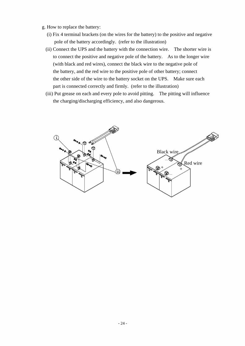
g. How to replace the battery: (i) Fix 4 terminal brackets (on the wires for the battery) to the positive and negative
pole of the battery accordingly. (refer to the illustration) (ii) Connect the UPS and the battery with the connection wire. The shorter wire is
to connect the positive and negative pole of the battery. As to the longer wire (with black and red wires), connect the black wire to the negative pole of the battery, and the red wire to the positive pole of other battery; connect the other side of the wire to the battery socket on the UPS. Make sure each part is connected correctly and firmly. (refer to the illustration)
(iii) Put grease on each and every pole to avoid pitting. The pitting will influence the charging/discharging efficiency, and also dangerous.
Black wire
Red wire +
-+
-
- 25 -
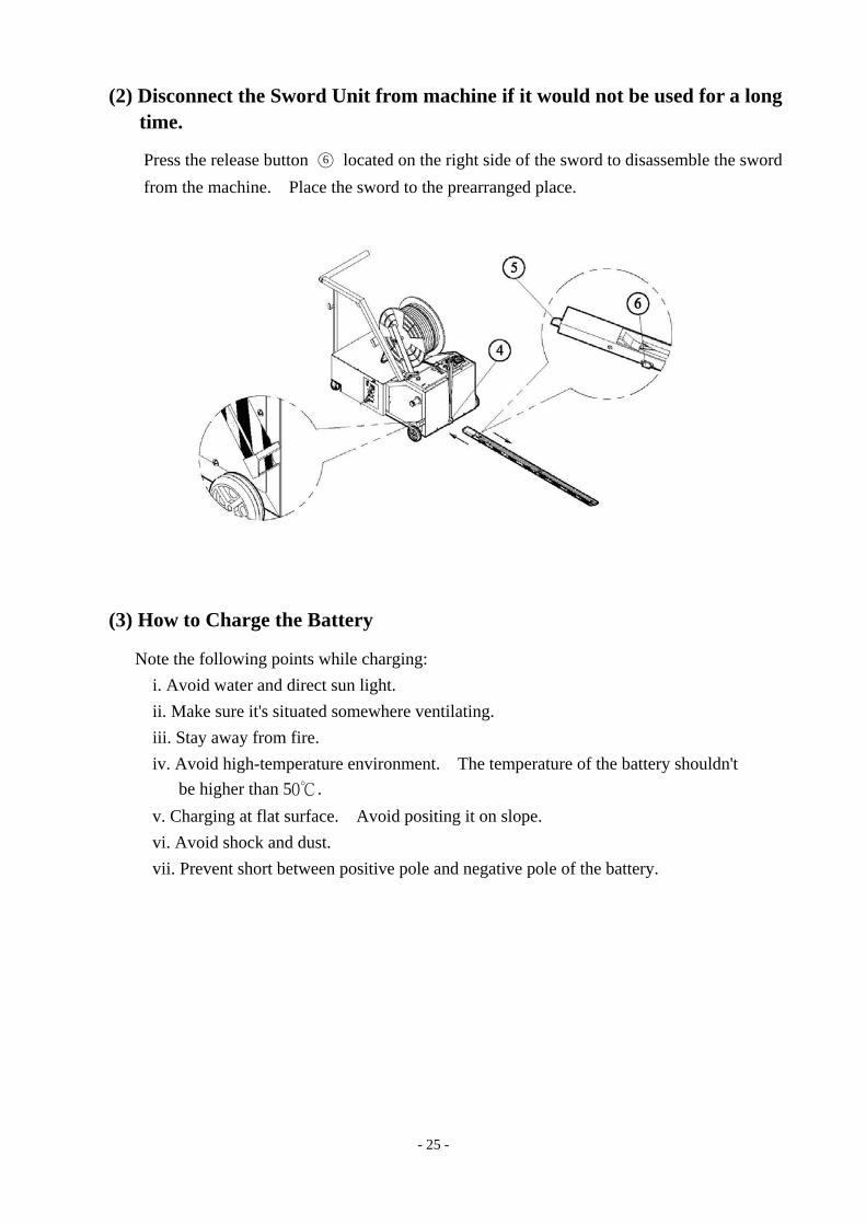
(2) Disconnect the Sword Unit from machine if it would not be used for a long time.
Press the release button ○6 located on the right side of the sword to disassemble the sword from the machine. Place the sword to the prearranged place.
(3) How to Charge the Battery
Note the following points while charging: i. Avoid water and direct sun light. ii. Make sure it's situated somewhere ventilating. iii. Stay away from fire. iv. Avoid high-temperature environment. The temperature of the battery shouldn't
be higher than 50℃. v. Charging at flat surface. Avoid positing it on slope. vi. Avoid shock and dust. vii. Prevent short between positive pole and negative pole of the battery.
- 26 -
(4) Maintenance of the Machine
Before any maintenance or repairs on the machine, set the Main Power Switch to "O" (OFF). Wait about 5 minutes for cooling down the heater to avoid burns with this area.
1. Cleaning and Lubrication
The high reliability and long service life of the strapping machine will depend on regular cleaning and maintenance. ATTENTION! All the important strap transport components, such as the tension rollers and the strap guides, must be kept free from oil and grease. (lubricant)
The lubricant has to be non-resinous. The lubricant is SAE 30
2. Maintenance
Only use original spare parts supplied by manufacturer.
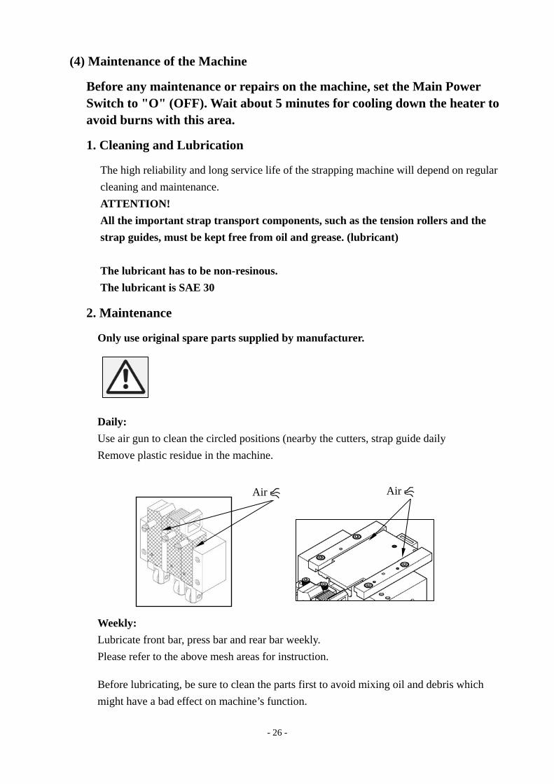
Daily: Use air gun to clean the circled positions (nearby the cutters, strap guide daily Remove plastic residue in the machine.
Weekly: Lubricate front bar, press bar and rear bar weekly. Please refer to the above mesh areas for instruction.
Before lubricating, be sure to clean the parts first to avoid mixing oil and debris which might have a bad effect on machine’s function.
Air Air
- 27 -
Monthly :( or 3,000 strapping cycles) Clean both sides of heater plate and polish with fine sandpaper if necessary. ATTENTION: Make sure the welding plate is cool first!! Check cam rollers of seal head for easy movement. Slide table back to home position automatically by the spring tension. Be sure to clean any debris in the tension roller.
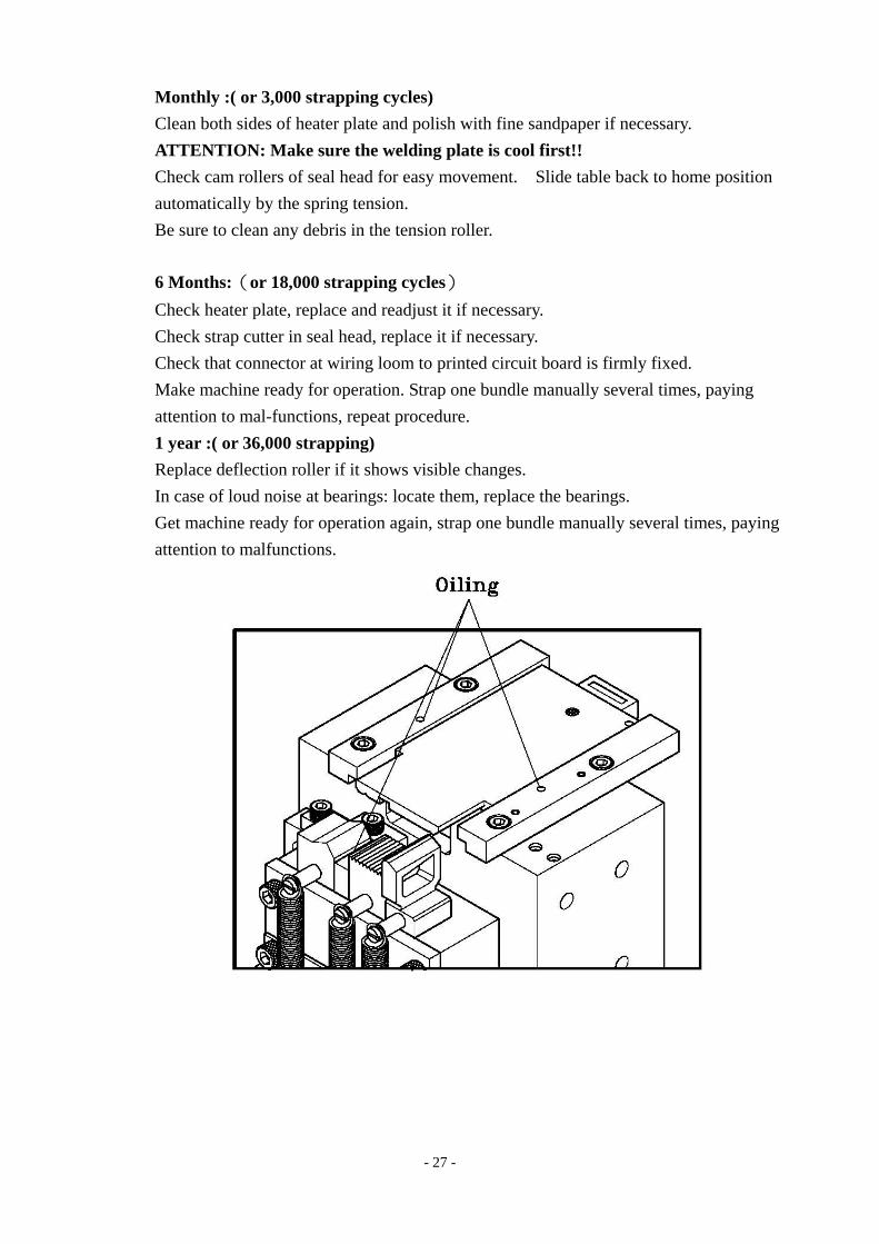
6 Months:(or 18,000 strapping cycles) Check heater plate, replace and readjust it if necessary. Check strap cutter in seal head, replace it if necessary. Check that connector at wiring loom to printed circuit board is firmly fixed. Make machine ready for operation. Strap one bundle manually several times, paying attention to mal-functions, repeat procedure. 1 year :( or 36,000 strapping) Replace deflection roller if it shows visible changes. In case of loud noise at bearings: locate them, replace the bearings. Get machine ready for operation again, strap one bundle manually several times, paying attention to malfunctions.
- 28 -
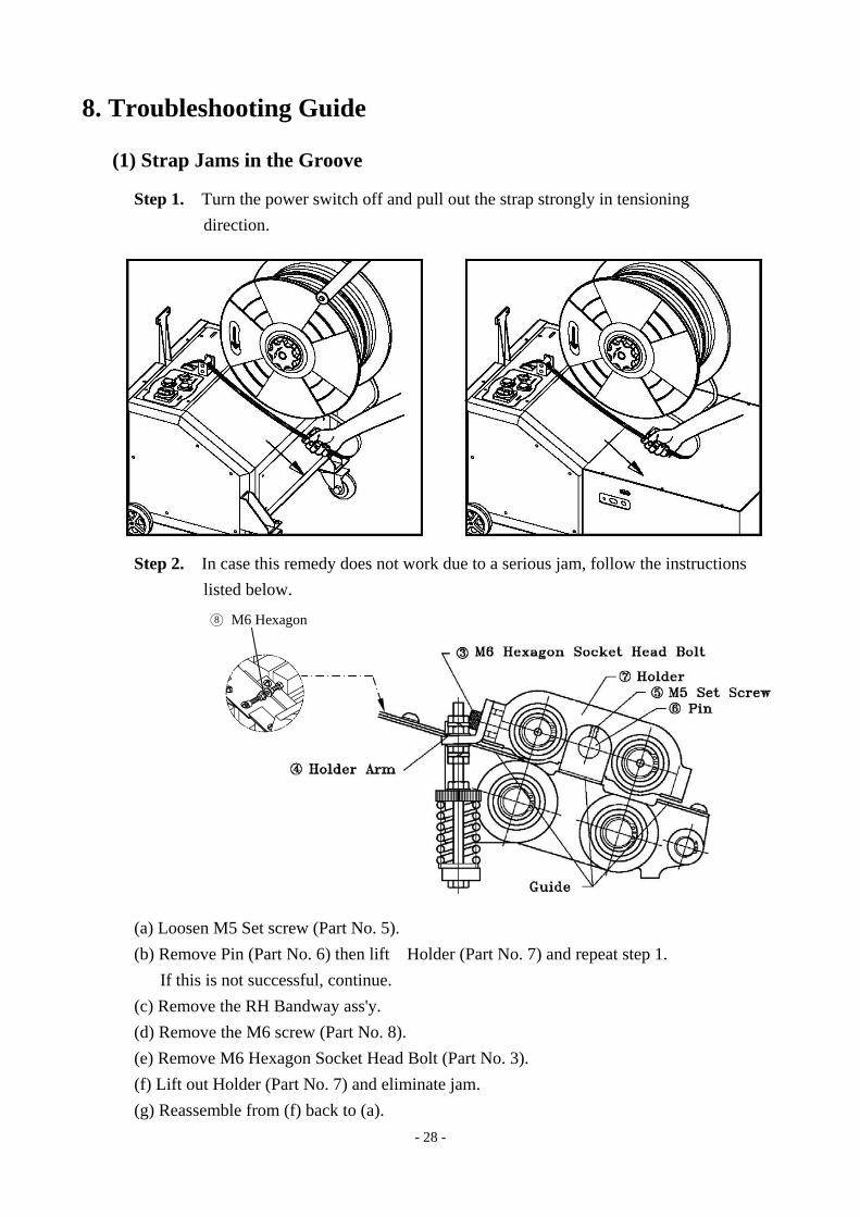
8. Troubleshooting Guide
(1) Strap Jams in the Groove
Step 1. Turn the power switch off and pull out the strap strongly in tensioning direction.
Step 2. In case this remedy does not work due to a serious jam, follow the instructions listed below.
(a) Loosen M5 Set screw (Part No. 5). (b) Remove Pin (Part No. 6) then lift Holder (Part No. 7) and repeat step 1.
If this is not successful, continue. (c) Remove the RH Bandway ass'y. (d) Remove the M6 screw (Part No. 8). (e) Remove M6 Hexagon Socket Head Bolt (Part No. 3). (f) Lift out Holder (Part No. 7) and eliminate jam. (g) Reassemble from (f) back to (a).
○8 M6 Hexagon
- 29 -
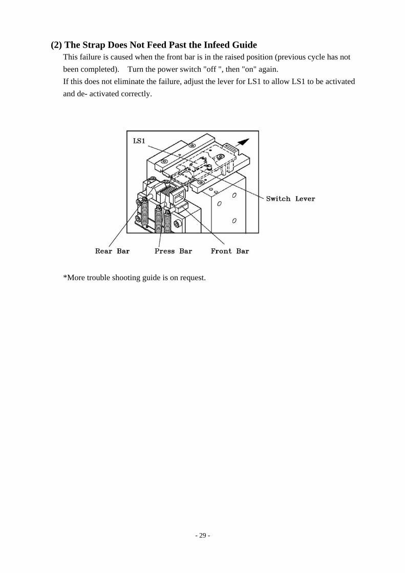
(2) The Strap Does Not Feed Past the Infeed Guide This failure is caused when the front bar is in the raised position (previous cycle has not been completed). Turn the power switch "off ", then "on" again. If this does not eliminate the failure, adjust the lever for LS1 to allow LS1 to be activated and de- activated correctly.
*More trouble shooting guide is on request.
- 30 -
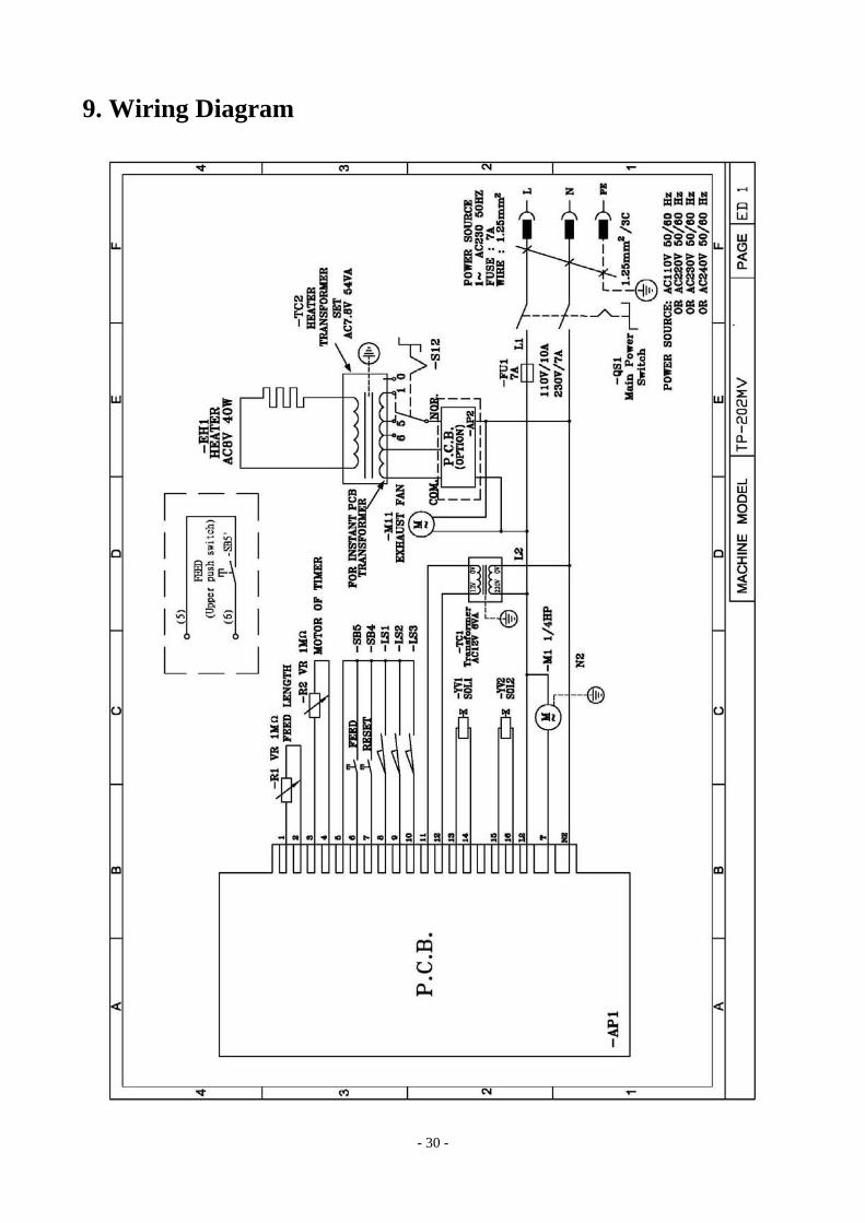
9. Wiring Diagram
PART II
CONTENTS
1. Strapping Head Unit ………………………………………...…1
2. Bandway Unit…………………………………………………17
3. Reel Unit………………………………………………………21
4. Body Frame Group……………………………………………25
5. Electric Control Unit …………………………………………29
6. Battery Unit ………………………………………………… 34
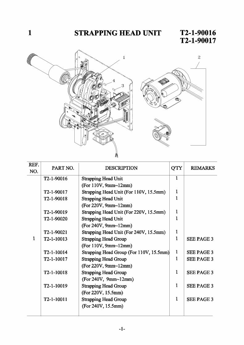

1-1 STRAPPING HEAD UNIT T2-1-90016T2-1-90017
REF.NO. PART NO. DESCRIPTION Q'TY REMARKS
2 T2-1-20000 Bracket Gruop (For 110V) 1 SEE PAGE 15T2-1-20001 Bracket Gruop (For 220V) 1 SEE PAGE 15T2-1-20002 Bracket Gruop (For 240V) 1 SEE PAGE 15
3 LA-50082 Label (LS-3) 14 LA-50095 Label (LS-4) 1
-2-
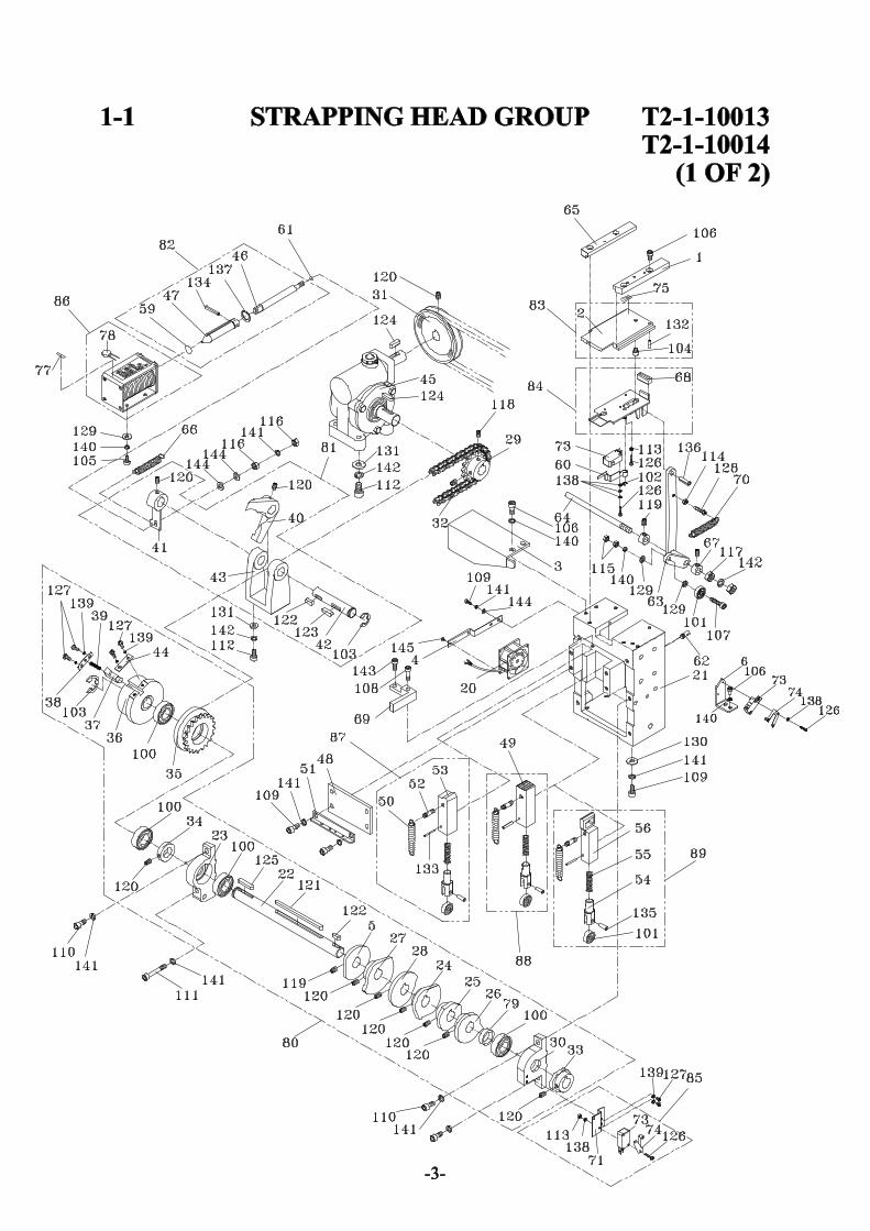
1-1 STRAPPING HEAD GROUP T2-1-10013T2-1-10014
(1 OF 2)REF.NO. PART NO. DESCRIPTION Q'TY REMARKS
T2-1-10013 Strapping Head Group 1(For 110V, 9mm~12mm)
T2-1-10014 Strapping Head Group 1(For 110V, 15.5mm)
T2-1-10017 Strapping Head Group 1(For 220V, 9mm~12mm)
T2-1-10018 Strapping Head Group 1(For 240V, 9mm~12mm)
T2-1-10019 Strapping Head Group 1(For 220V, 15.5mm)
T2-1-10011 Strapping Head Group 1(For 240V, 15.5mm)
1 T2-1-10010 Guide (R) 12 T2-1-10020 Slide 13 T2-1-10030 Protect Cover 14 T2-1-10040 Fan Support 15 T2-1-10050 Spacer 16 T2-5-10310 Micro Switch Bracket 1
20 TF-021 Fan (For 110V) 1TF-021-1 Fan (For 220V/230V/240V) 1
21 T5-1-10110 Main Body Block 122 TA-003 Cam Shaft 123 TA-008-2 Bearing Support (L) 124 TA-012A Grip Cam 125 TA-012B Grip Cam 126 TA-014 Separator Cam 127 TA-015A Rear Bar Cam 128 TA-015B Heater Cam 129 TA-016 Sprocket 130 TA-017-2 Bearing Support (R) 131 TA-018 Pulley 132 TA-022 Chain 133 TA-024 Back Cam 134 TA-025 Collar 1
-4-
1-1 STRAPPING HEAD GROUP T2-1-10013T2-1-10014
(1 OF 2)REF.NO. PART NO. DESCRIPTION Q'TY REMARKS
35 TA-027 Sprocket 136 TA-028 Housing 137 TA-029 Pin 138 TA-030 Holder 139 TA-032 Spring 140 TA-033 Stop Arm 141 TA-034 Clutch Arm 142 TA-035 Shaft 143 TA-037 Clutch Support 144 TA-040 Guide 145 TA-042 Gear Box 146 TA-058 Pull Shaft 147 TA-060 Solenoid Shaft 148 TA-067 Bar Guide Lid 149 TA-069 Press Bar 150 TA-071 Return Spring 351 TA-072 Spring Hook 152 TA-073 Spring Hook 353 TA-074 Rear Bar 154 TA-075 Plunger 355 TA-078 Spring 356 TA-079 Front Bar 1
59 TA-086 Seal 160 TA-087 Switch Lever 161 TA-088 Seal (Small) 162 TA-089 Spring Hook 163 TA-090 Arm 164 TA-094 Shaft 165 TA-095 Guide (L) 166 TA-114 Spring 167 TA-229 Collar 268 TA-236 Rubber Buffer 169 TA-239 Cutter Holder 170 TB-114 Return Spring 1
-5-

1-1 STRAPPING HEAD GROUP T2-1-10013T2-1-10014
(1 OF 2)REF.NO. PART NO. DESCRIPTION Q'TY REMARKS
71 TF-002 Micro Switch Bracket 1
73 TF-006 Micro Switch (LS-1, LS-3) 374 TF-009 Switch Trigger 275 LA-50080 Label 1
77 LA-50084 Label(SOL-2) 178 TF-071 Varistor 179 TA-241 Spacer 180 T2-1-10200 Cam Ass'y 181 TA-035A Stop Arm Ass'y 182 TA-058A Pull Shaft Ass'y 183 T2-1-10240 Slide Ass'y 184 TA-083A Separator Ass'y 185 TF-002A Micro Switch Bracket Ass'y 186 TF-003A D.C.Solenoid Ass'y (For 110V) 1
TF-003A-1 D.C.Solenoid Ass'y 1(For 220V/230V/240V)
87 T5-1-13000 Rear Bar Ass'y 188 T5-1-14000 Press Bar Ass'y 189 T5-1-15000 Front Bar Ass'y 1
100 BR6003ZZ Bearing, 6003ZZ 4101 BR635ZZ Bearing, 635ZZ 4102 ER03 Snap Ring, E-3 1103 ER12 Snap Ring, E-12 2104 HBS0505.2 HBS, M5x5.2 1105 HBS0510 HBS, M5x10 4106 HBS0512 HBS, M5x12 8107 HBS0525 HBS, M5x25 1108 HBS0525H HBS, M5x25 (H) 1109 HBS0616 HBS, M6x16 16110 HBS0620 HBS, M6x20 3111 HBS0645H HBS, M6x45 (H) 1112 HBS0820 HBS, M8x20 4
-6-
1-1 STRAPPING HEAD GROUP T2-1-10013T2-1-10014
(1 OF 2)REF.NO. PART NO. DESCRIPTION Q'TY REMARKS
113 HN03 HN, M3 1114 HN04 HN, M4 1115 HN05 HN, M5 2116 HN06 HN, M6 2117 HN08 HN, M8 2118 HSS0506G HSS, M5x6 (G) 2119 HSS0606G HSS, M6x6 (G) 3120 HSS0608G HSS, M6x8 (G) 10121 KYA0505101 Key, 5x5x101 1122 KYA050515 Key, 5x5x15 2123 KYA050520 Key, 5x5x20 1124 KYA050525 Key, 5x5x25 2125 KYA050530 Key, 5x5x30 1126 PMS0315 PMS, M3x15 8127 PMS0408 PMS, M4x8 6128 PMS0420 PMS, M4x20 1129 PW05 PW, M5 2130 PW06C PW, M6 (C) 8131 PW08C PW, M8 (C) 4132 SP0314 Spring Pin, 3x14 1133 SP0318 Spring Pin, 3x18 3134 SP0414 Spring Pin, 4x14 1135 SP0514 Spring Pin, 5x14 3136 SP0620 Spring Pin, 6x20 1137 SR12 Stop Ring, S-12 1138 SW03 SW, M3 5139 SW04 SW, M4 4140 SW05 SW, M5 9141 SW06 SW, M6 17142 SW08 SW, M8 5143 HBS0516 HBS, M5x16 2144 PW06A PW, M6 (A) 4145 PMS0510 PMS, M5x10 2
-7-
1-1 STRAPPING HEAD GROUP T2-1-10013T2-1-10014
(2 OF 2)REF.NO. PART NO. DESCRIPTION Q'TY REMARKS
1 T2-1-10060 Holder Arm 12 T2-1-10082 Outlet Cover 13 T2-1-10071 Outlet Guide 14 T2-1-10090 Bracket 15 T2-1-10101 Bracket Sub Ass'y 16 T2-1-10110 Pin 17 T2-1-10120 Heater Arm 18 T2-1-10130 Bracket 19 T2-1-10140 Bandway (For 9mm~12mm) 1
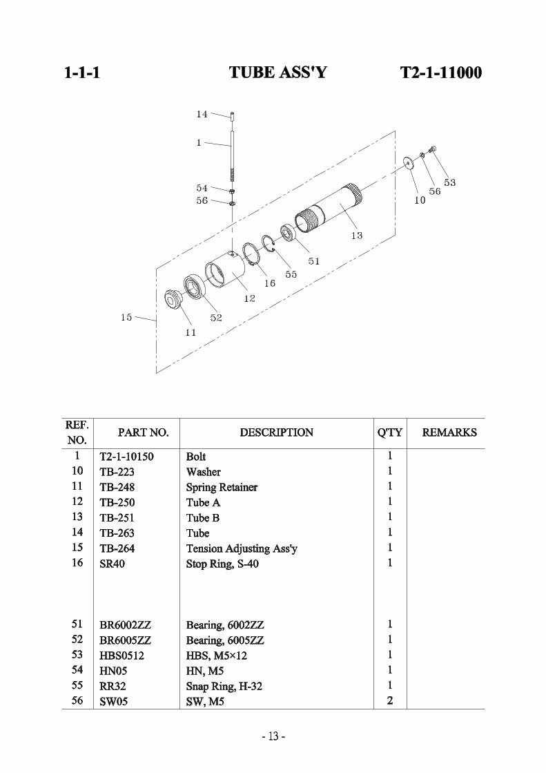
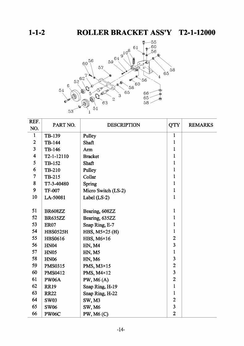
T2-1-10141 Bandway (For 15mm) 110 T2-1-10172 Holder 111 T2-1-10250 Plate 212 T2-1-10102 Bracket 114 T2-1-11000 Tube Ass'y 1 SEE PAGE 1315 T2-1-12000 Roller Bracket Ass'y 1 SEE PAGE 14
17 T6-1-72140 Spring 118 TB-102 Heater Arm 119 TB-224 Spring Retainer 121 TB-107 Side Plate 122 TB-113 Heater Ass'y 123 TB-114 Return Spring 124 TB-115 Spring 125 TB-117 Roller 426 TB-118A Shaft 1
(For Outside Tension Adjustment)27 TB-122 Shaft 128 TB-124 Pin 129 TB-127 Gear 330 TB-128 Collar 731 TB-129 Feed Gear 132 TB-130 Spring 133 TB-133 Nut 134 TB-134 Gear 135 TB-143 Round Belt 1
-9-
1-1 STRAPPING HEAD GROUP T2-1-10013T2-1-10014
(2 OF 2)REF.NO. PART NO. DESCRIPTION Q'TY REMARKS
36 TB-154 Spring 1
38 TB-162 Shaft 139 TB-164 Shaft 140 TB-165 Feed Arm 141 TB-168 Arm Pin 142 TB-170 Pulley 143 TB-175 Plate 144 TB-175A Plate 145 TB-176 Friction Disc 246 TB-177 Pull Shaft 147 TB-183 Spring 148 TB-184 Stop Bracket 149 TB-186 Spring 150 TB-187 Spring 151 TB-189 Retainer 152 TB-192 Roller 153 TB-193 Cover 154 TB-199 Pin 156 TB-203 Guide 157 TB-205 Guide 158 TB-206 Cover 159 TB-207 Cover-Side 160 TB-209 Band Plate 161 TB-223 Washer 162 TB-256 Corrector 163 TB-262 Tube 1
65 TF-003A D.C.Solenoid Ass'y (For 110V) 1TF-003A-1 D.C.Solenoid Ass'y 1
(For 220V/230V/240V)66 LA-50083 Label (SOL-1) 167 TF-071 Varistor 168 TA-060 Solenoid Shaft 169 TA-086 Seal 1
-10-
1-1 STRAPPING HEAD GROUP T2-1-10013T2-1-10014
(2 OF 2)REF.NO. PART NO. DESCRIPTION Q'TY REMARKS
71 T2-1-10182 Roller Holder Ass'y 172 T2-1-10232 Bracket Ass'y 173 TB-165A Feed Arm Ass'y 174 TB-170A Pulley Ass'y 175 TB-177A Pull Shaft Ass'y 1
79 FMS0412 FMS, M4x12 280 BR6002ZZ Bearing, 6002ZZ 981 BR635ZZ Bearing, 635ZZ 382 ER06 Snap Ring, E-6 183 PMS0416 FMS, M4x16 284 FLG06 FLG, M6 685 FMS0406 FMS, M4x6 286 FMS0408 FMS, M4x8 887 HB06100H HB, M6x100 (H) 188 HB0680 HB, M6x80 189 HBS0416 HBS, M4x16 290 HBS0440H HBS, M4x40 (H) 291 HBS0510 HBS, M5x10 492 HBS0512 HBS, M5x12 193 HBS0516 HBS, M5x16 294 HBS0550 HBS, M5x50 195 HBS0612 HBS, M6x12 296 HBS0616 HBS, M6x16 297 HBS0620 HBS, M6x20 1098 TMS0512 TMS, M5x12 199 HN04 HN, M4 7100 HN05 HN, M5 5101 HN06 HN, M6 7102 HN08 HN, M8 1103 PMS0420 PMS, M4x20 1104 HSS0508G HSS, M5x8 (G) 1105 HSS0606G HSS, M6x6 (G) 1
-11-
1-1 STRAPPING HEAD GROUP T2-1-10013T2-1-10014
(2 OF 2)REF.NO. PART NO. DESCRIPTION Q'TY REMARKS
106 KYA050515 Key, 5x5x15 7107 KYA050520 Key, 5x5x20 2108 KYA050538 Key, 5x5x38 1109 PMS0410 PMS, M4x10 3110 PMS0412 PMS, M4x12 2
112 PW04 PW, M4 3113 PW05 PW, M5 2114 PW06A PW, M6 (A) 12115 RR32 Snap Ring, H-32 1116 SP0414 Spring Pin, 4x14 1117 SP0520 Spring Pin, 5x20 1118 SR10 Stop Ring, S-10 2119 SR12 Stop Ring, S-12 1120 SR15 Stop Ring, S-15 10121 SW04 SW, M4 9122 SW05 SW, M5 7123 SW06 SW, M6 13124 SW08 SW, M8 3
-12-
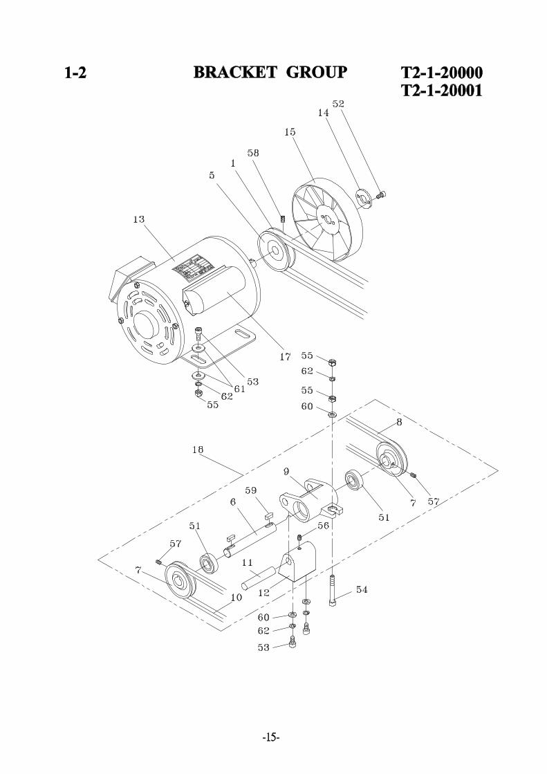
1-2 BRACKET GROUP T2-1-20000T2-1-20001
REF.NO. PART NO. DESCRIPTION Q'TY REMARKS
T2-1-20000 Bracket Gruop (For 110V) 1T2-1-20001 Bracket Gruop (For 220V) 1T2-1-20002 Bracket Gruop (For 240V) 1
1 T2-1-20010 Belt 15 TA-020 Pulley 16 TB-137 Shaft 17 TB-141 Pulley 28 TB-157 V-Belt 19 TB-160 Bracket 1
10 TB-173 V-Belt 111 TB-231 Pin 112 TB-232 Bracket 113 TF-001 Motor (For 110V, 60HZ) 1
TF-001-1D Motor (For 220V, 50HZ) 1TF-001-1B Motor (For 220V, 60HZ) 1TF-001-2 Motor (For 240V, 50HZ) 1TF-001-B Motor (For 100V, 50/60HZ) 1
14 TF-022 Washer 115 TF-028 Fan 117 TF-044 Start Capacitor (220V, 50HZ) 1
TF-045 Start Capacitor (220V, 60HZ/240V, 50HZ) 1TF-046 Start Capacitor (110V, 60HZ) 1TF-047 Start Capacitor (100V, 50/60HZ) 1
18 TB-160B Bracket Ass'y 1 51 BR6002ZZ Bearing, 6002ZZ 252 HBS0516 HBS, M5x16 153 HBS0620 HBS, M6x20 654 HBS0665H HBS, M6x65 (H) 155 HN06 HN, M6 656 HSS0506G HSS, M5x6 (G) 157 HSS0508G HSS, M5x8 (G) 258 HSS0608G HSS, M6x8 (G) 159 KYA050515 Key, 5x5x15 260 PW06A PW, M6 (A) 361 PW06C PW, M6 (C) 862 SW06 SW, M6 7
-16-
2-1 SWORD UNIT T2-2-10000REF.NO. PART NO. DESCRIPTION Q'TY REMARKS
1 T2-2-10010 Bandway Hook 12 T2-2-10020 Rear Bandway Rack 13 T2-2-10030 RH Bandway Ass'y 1
10 T2-2-10100 LH Bandway Ass'y 111 T2-2-10150 Front Bandway Rack 1
20 T6-2-11140 RH Bandway Flap Pin (Rear) 421 T6-2-11150 RH Bandway Flap Spring 422 T6-2-11160 RH Bandway Flap Pin (Front) 423 T7-1-10310 Spring 1
51 FMS0408 FMS, M4x8 152 HBS0608 HBS, M6x8 153 HN04 HN, M4 154 NTE04 NTE, M4 155 FMS0610 FMS, M6x10 1156 PW04 PW, M4 257 SW04 SW, M4 158 SW06 SW, M6 159 PMS0416 PMS, M4x16 1
-19-
3-1 REEL CONTROL GROUP T6-4-20002REF.NO. PART NO. DESCRIPTION Q'TY REMARKS
1 T6-4-20011 Reel Support 12 T6-4-20017 Brake Belt 13 T6-4-20021 Lining Fixed Bracket 14 T6-4-20024 Brake Arm 1
7 TC-005 Lid 18 TC-009 Brake Shaft 19 TC-011 Washer 1
10 TC-013 Inner Flange 111 TC-014 Outer Flange 112 TC-015 Protector 1
14 TC-020 Pin 115 TC-021 Split Pin 116 TC-024 Brake Adjuster 117 TC-025 Spring 118 TC-045-1 Fixing Brake Lining Bracket 119 TC-050 Lining Holder 1
21 TC-076 Washer 122 TC-094 Spacer 123 TD-003 Reel Shaft (LH) 124 TD-016 Reel Nut Handle (LH) 1
26 LA-30200 Label 127 LA-30210 Label 128 TE-027 Roller Holder 129 TE-028 Roller 130 TE-029 Pin 1
-23-
3-1 REEL CONTROL GROUP T6-4-20002REF.NO. PART NO. DESCRIPTION Q'TY REMARKS
51 BR6003ZZ Bearing, 6003ZZ 252 ER04 Snap Ring, E-4 253 ER19 Snap Ring, E-19 154 HB0816 HB, M8x16 155 HBS0525H HBS, M5x25 (H) 156 HBS0616 HBS, M6x16 257 HBS0825N HBS, M8x25 (N) 358 HN05 HN, M5 259 HN06 HN, M6 2
61 SW08 SW, M8 3
63 PW08C PW, M8 (C) 364 SR10 Stop Ring, S-10 165 SR15 Stop Ring, S-15 166 SR20 Stop Ring, S-20 2
-24-

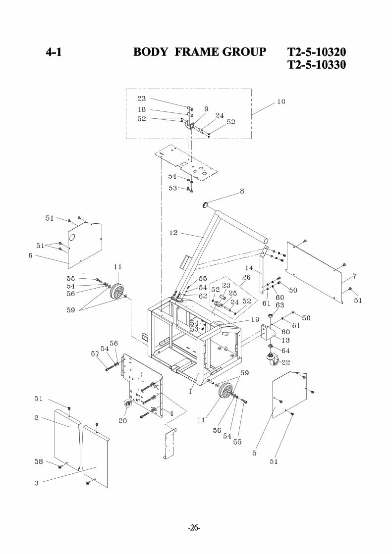
4-1 BODY FRAME GROUP T2-5-10320T2-5-10330
REF.NO. PART NO. DESCRIPTION Q'TY REMARKS
T2-5-10320 Body Frame Group (For TP-202MV) 1T2-5-10330 Body Frame Group (For TP-202MVB) 1
1 T2-5-10011 Body Frame 12 T2-5-10020 Front Plate (LH) 13 T2-5-10030 Front Plate (RH) 14 T2-5-10040 Bracket 15 T2-5-10051 Plate (RH) 16 T2-5-10061 Plate (LH) 17 T2-5-10250 Rear Cover 18 T2-5-10080 Tube Plug 19 T2-5-10090 Roller Bracket 1
10 T2-5-10100 Roller Bracket Group 111 T2-5-10230 Caster 212 T2-5-10240 Pushing Bar (Only TP-202MV) 113 T2-5-10260 Caster Bracket (Only TP-202MV) 214 T2-5-10280 Pushing Bar Support (Only TP-202MV) 118 T2-3-10260 Roller 119 LA-30070 Label 120 T2-1-10260 Bolt Set (M8×20) 122 T7-5-10180 Caster (Free) 223 TC-019 Roller 224 TD-048 Shaft 325 TD-047 Roller Bracket 126 TD-047A Roller Bracket Ass'y 150 HBS0816N HBS, M8x16 (N)(Only TP-202MV) 851 TMS0608 TMS, M6x8 1452 SR10 Stop Ring, S-10 653 HBS0608N HBS, M6x8 (N) 454 SW06 SW, M6 (For TP-202MV) 16
SW, M6 (For TP-202MVB) 1255 HBS0616N HBS, M6x16 (N)(For TP-202MV) 6
HBS, M6x16 (N)(For TP-202MVB) 256 PW06C PW, M6 (C) 857 HBS0620 HBS, M6x20 658 FMS0616 FMS, M6x16 259 PW12C PW, M12 (C) 4
-27-

4-1 BODY FRAME GROUP T2-5-10320T2-5-10330
REF.NO. PART NO. DESCRIPTION Q'TY REMARKS
60 SW08 SW, M8 (Only TP-202MV) 861 PW08C PW, M8 (C)(Only TP-202MV) 862 PW06A PW, M6 (A)(Only TP-202MV) 463 HN5/8 HN, 5/8" 264 SW16 SW, M16 2
-28-
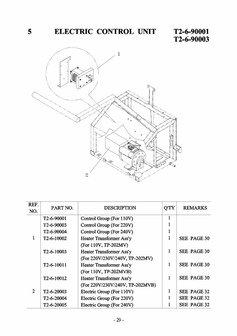
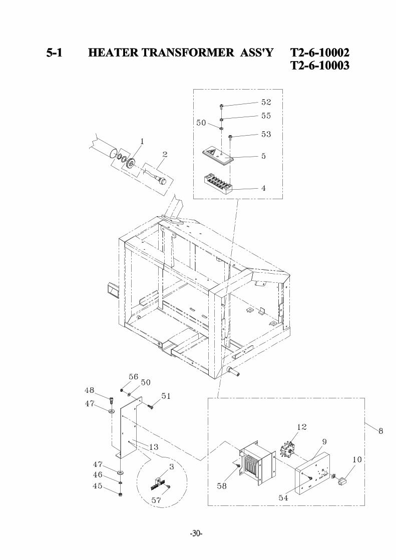
5-1 HEATER TRANSFORMER ASS'Y T2-6-10002T2-6-10003
REF.NO. PART NO. DESCRIPTION Q'TY REMARKS
T2-6-10002 Heater Transformer Ass'y 1(For 110V, TP-202MV)
T2-6-10003 Heater Transformer Ass'y 1(For 220V/230V/240V, TP-202MV)
T2-6-10011 Heater Transformer Ass'y 1(For 110V, TP-202MVB)
T2-6-10012 Heater Transformer Ass'y 1(For 220V/230V/240V, TP-202MVB)
1 T2-6-10010 Tube Plug 12 T2-6-10020 Wire Ass'y (For TP-202MV) 1
T2-6-10021 Wire Ass'y (For TP-202MVB) 13 T5-4-10310 Earth Plate (5P) 14 TF-015 Terminal Bracket 15 TF-016 Cover (For CE) 18 TF-023A Heater Transformer Ass'y (For 110V) 1
TF-023A-1 Heater Transformer Ass'y 1(For 220V/230V/240V)
9 TF-024 Transformer Cover 110 TF-025 Knob 112 TF-027 Selector Switch 113 T2-6-10030 Transformer Bracket 1
45 HN06 HN, M6 246 SW06 SW, M6 247 PW06C PW, M6 (C) 448 HBS0616N HBS, M6×16 (N) 250 PW04 PW, M4 351 HBS0412N HBS, M4×12 (N) 152 PMS03.515 PMS, M3.5x15 253 PMS0408 PMS, M4x8 254 TMS0410 PMS, M4x10 455 SW03 SW, M3 256 HN04 HN, M4 157 TMS0412 TMS, M4x12 158 TMS0408 TMS, M4x8 4
-31-
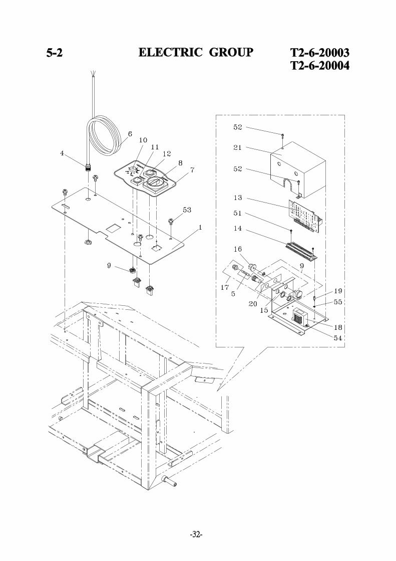
5-2 ELECTRIC GROUP T2-6-20003T2-6-20004
REF.NO. PART NO. DESCRIPTION Q'TY REMARKS
T2-6-20003 Electric Group (For 110V) 1T2-6-20004 Electric Group (For 220V) 1T2-6-20005 Electric Group (For 240V) 1
1 T2-6-20011 Control Plate 1
4 T6-6-10980 Cable Gland (PG11) 15 T6-6-30133 Fuse (For 10A/110V AC) 1
T6-6-30034 Fuse (For 7A/220V/230V/240V AC) 16 MV-6-10060 Power Cord (Europe Plug) 1
MV-6-10061 Power Cord (America Plug) 17 LA-10012 Label 18 TK-001 Main Power Switch 19 TG-002 Variable Resistor (1M ) 2
10 TG-003 Knob 111 TG-004 Reset Push Button Switch 112 TG-005 Feed Push Button Switch 113 T2-6-30250 PC Board 114 TG-008 PC Board Receptacle 115 TG-009 Base 116 TG-012 Knob 117 TG-013 Fuse Holder 118 TG-015 Transformer (For 110V) 1
TG-015-1 Transformer (For 220V) 1TG-015-2 Transformer (For 240V) 1
19 TG-016 Bolt 120 LA-20170 Label 121 TG-034 Cover 1
51 TMS0312 TMS, M3x12 252 TMS0408 TMS, M4x8 553 TMS0608 TMS, M6x8 454 PMS0408 PMS, M4x8 255 SW03 SW, M3 1
-33-
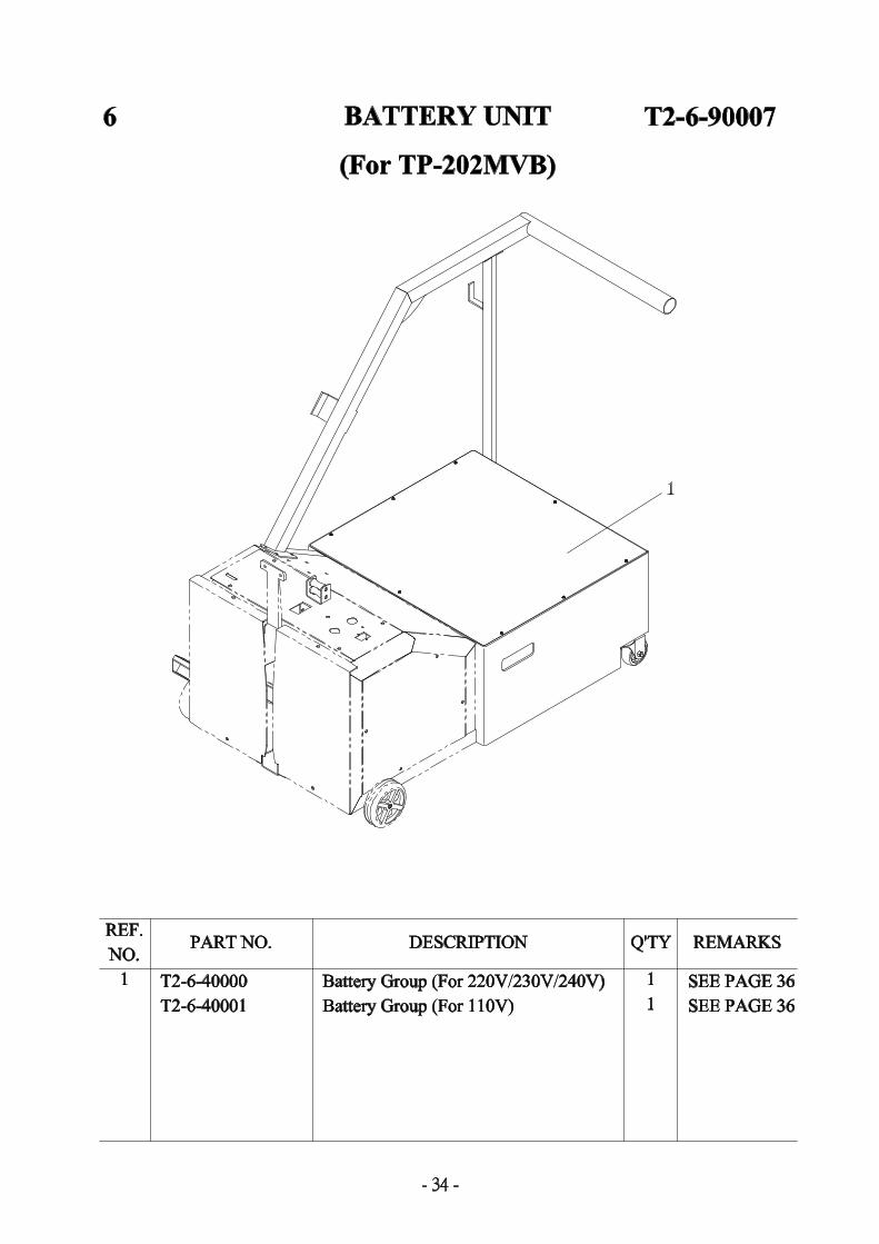
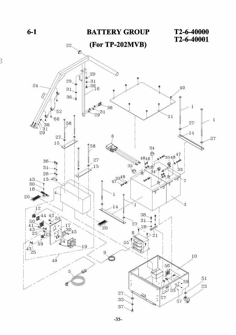
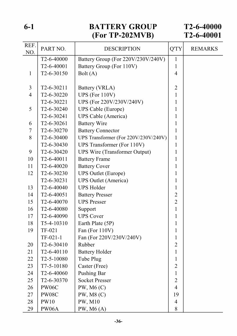
6-1 BATTERY GROUP T2-6-40000(For TP-202MVB) T2-6-40001
REF.NO. PART NO. DESCRIPTION Q'TY REMARKS
T2-6-40000 Battery Group (For 220V/230V/240V) 1T2-6-40001 Battery Group (For 110V) 1
1 T2-6-30150 Bolt (A) 4
3 T2-6-30211 Battery (VRLA) 24 T2-6-30220 UPS (For 110V) 1
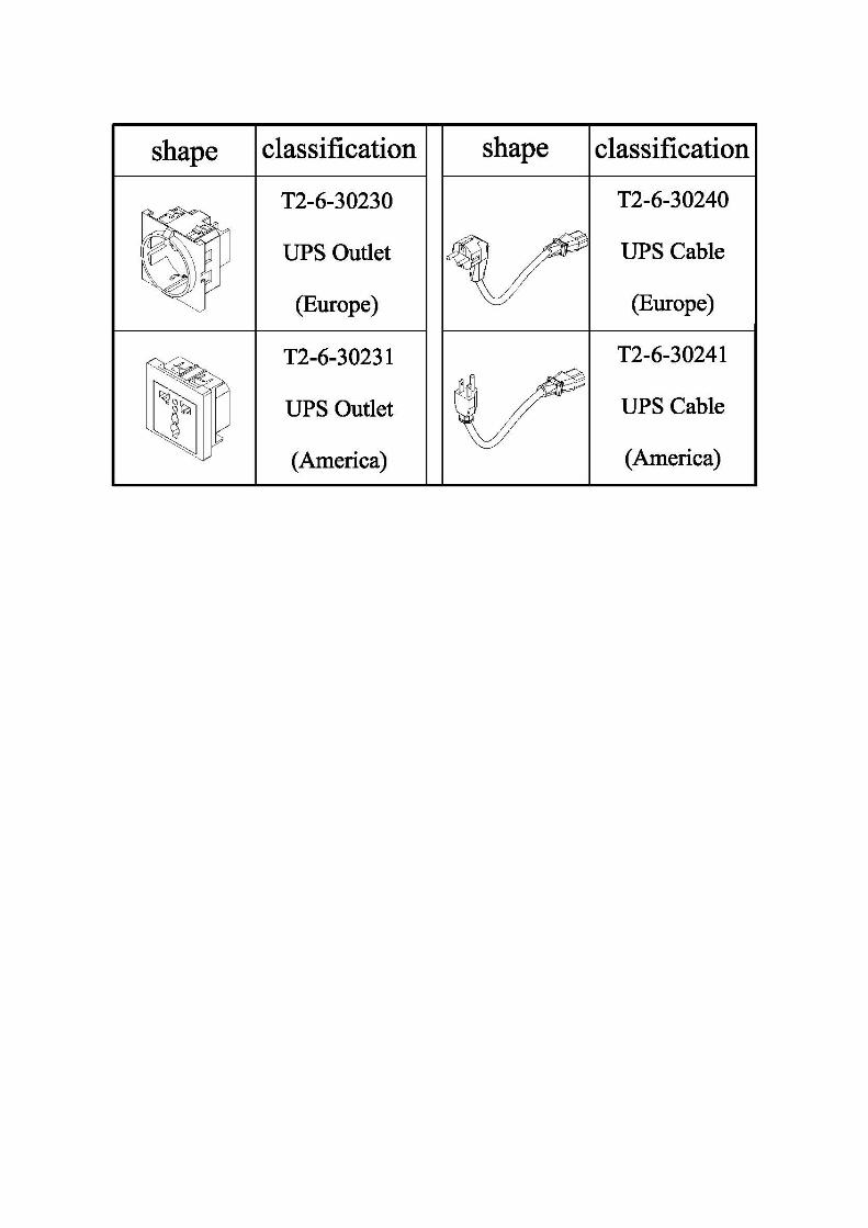
T2-6-30221 UPS (For 220V/230V/240V) 15 T2-6-30240 UPS Cable (Europe) 1
T2-6-30241 UPS Cable (America) 16 T2-6-30261 Battery Wire 17 T2-6-30270 Battery Connector 18 T2-6-30400 UPS Transformer (For 220V/230V/240V) 1
T2-6-30430 UPS Transformer (For 110V) 19 T2-6-30420 UPS Wire (Transformer Output) 1
10 T2-6-40011 Battery Frame 111 T2-6-40020 Battery Cover 112 T2-6-30230 UPS Outlet (Europe) 1
T2-6-30231 UPS Outlet (America) 113 T2-6-40040 UPS Holder 114 T2-6-40051 Battery Presser 215 T2-6-40070 UPS Presser 216 T2-6-40080 Support 117 T2-6-40090 UPS Cover 118 T5-4-10310 Earth Plate (5P) 119 TF-021 Fan (For 110V) 1
TF-021-1 Fan (For 220V/230V/240V) 120 T2-6-30410 Rubber 221 T2-6-40110 Battery Holder 122 T2-5-10080 Tube Plug 123 T7-5-10180 Caster (Free) 224 T2-6-40060 Pushing Bar 125 T2-6-30370 Socket Presser 226 PW06C PW, M6 (C) 427 PW08C PW, M8 (C) 1928 PW10 PW, M10 429 PW06A PW, M6 (A) 8
-36-
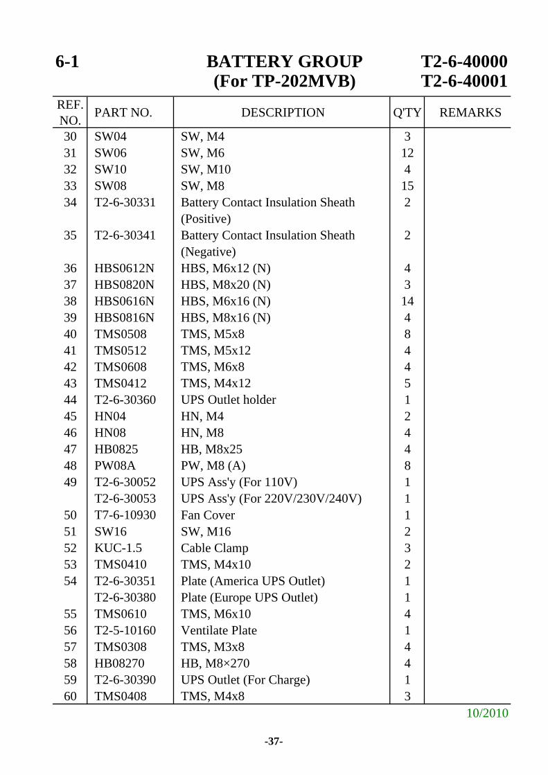
6-1 BATTERY GROUP T2-6-40000(For TP-202MVB) T2-6-40001
REF.NO. PART NO. DESCRIPTION Q'TY REMARKS
30 SW04 SW, M4 331 SW06 SW, M6 1232 SW10 SW, M10 433 SW08 SW, M8 1534 T2-6-30331 Battery Contact Insulation Sheath 2
(Positive)35 T2-6-30341 Battery Contact Insulation Sheath 2
(Negative)36 HBS0612N HBS, M6x12 (N) 437 HBS0820N HBS, M8x20 (N) 338 HBS0616N HBS, M6x16 (N) 1439 HBS0816N HBS, M8x16 (N) 440 TMS0508 TMS, M5x8 841 TMS0512 TMS, M5x12 442 TMS0608 TMS, M6x8 443 TMS0412 TMS, M4x12 544 T2-6-30360 UPS Outlet holder 145 HN04 HN, M4 246 HN08 HN, M8 447 HB0825 HB, M8x25 448 PW08A PW, M8 (A) 849 T2-6-30052 UPS Ass'y (For 110V) 1
T2-6-30053 UPS Ass'y (For 220V/230V/240V) 150 T7-6-10930 Fan Cover 151 SW16 SW, M16 252 KUC-1.5 Cable Clamp 353 TMS0410 TMS, M4x10 254 T2-6-30351 Plate (America UPS Outlet) 1
T2-6-30380 Plate (Europe UPS Outlet) 155 TMS0610 TMS, M6x10 456 T2-5-10160 Ventilate Plate 157 TMS0308 TMS, M3x8 458 HB08270 HB, M8×270 459 T2-6-30390 UPS Outlet (For Charge) 160 TMS0408 TMS, M4x8 3
10/2010
-37-