semistructured database design web information systems
TRANSCRIPT
SemistructuredDatabase Design
Web Information Systems Engineeringand Internet Technologies
Book Series
Series Editor: Yanchun Zhang, Victoria University, Australia
Editorial Board:Robin Chen, AT&TUmeshwar Dayal, HPArun Iyengar, IBMKeith Jeffery, Rutherford Appleton LabXiaohua Jia, City University of Hong KongYahiko Kambayashi† Kyoto UniversityMasaru Kitsuregawa, Tokyo UniversityQing Li, City University of Hong KongPhilip Yu, IBMHongjun Lu, HKUSTJohn Mylopoulos, University of TorontoErich Neuhold, IPSITamer Ozsu, Waterloo UniversityMaria Orlowska, DSTCGultekin Ozsoyoglu, Case Western Reserve UniversityMichael Papazoglou, Tilburg UniversityMarek Rusinkiewicz, Telcordia TechnologyStefano Spaccapietra, EPFLVijay Varadharajan, Macquarie UniversityMarianne Winslett, University of Illinois at Urbana-ChampaignXiaofang Zhou, University of Queensland

SemistructuredDatabase Design
Tok Wang LingMong Li Lee
National University of Singapore
Gillian DobbieThe University of Auckland
Springer

eBook ISBN: 0-387-23568-XPrint ISBN: 0-387-23567-1
Print ©2005 Springer Science + Business Media, Inc.
All rights reserved
No part of this eBook may be reproduced or transmitted in any form or by any means, electronic,mechanical, recording, or otherwise, without written consent from the Publisher
Created in the United States of America
Boston
©2005 Springer Science + Business Media, Inc.
Visit Springer's eBookstore at: http://ebooks.kluweronline.comand the Springer Global Website Online at: http://www.springeronline.com
Contents
List of FiguresList of TablesPreface
INTRODUCTION1.
Chapter Overview1.1
DATA MODELS FOR SEMISTRUCTURED DATA2.
Document Type Definition
DOM, OEM and DataGuide
S3-graph
CM Hypergraph and Scheme Tree
EER and XGrammar
AL-DTD and XML Tree
ORA-SS
Discussion
2.1
2.2
2.3
2.4
2.5
2.6
2.7
2.8
ixxiiixv
1
3
7
8
12
16
18
21
24
28
32
37
37
49
52
55
57
59
60
62
3. ORA-SS
ORA-SS Schema Diagram
ORA-SS Data Instance Diagram
ORA-SS Functional Dependency Diagram
ORA-SS Inheritance Hierarchy Diagram
Discussion
3.1
3.2
3.3
3.4
3.5
SCHEMA EXTRACTION4.
Basic Extraction Rules
Schema Extraction Algorithm
4.1
4.2
vi
Example
Discussion
Summary
4.3
4.4
4.5
NORMALIZATION5.
Motivating Example
Background
A Normal Form For Semistructured Schemas
Converting Schemas into the Normal Form
Discussion
66
74
75
77
78
82
85
89
5.1
5.2
5.3
5.4
5.5
VIEWS6.
Motivating Example
The Select Operator
The Drop Operator
The Join Operator
The Swap Operator
Design Rules for IDentifier Dependency Relationship
Example of Designing View
Related Work
Summary
6.1
6.2
6.3
6.4
6.5
6.6
6.7
6.8
6.9
107
111
112
116
117
121
125
132
134
136
138
139
139
141
143
146
150
153
154
158
160
161
165
PHYSICAL DATABASE DESIGN7.
Relational Database Physical Design
IMS Database Physical Design
Redundancy in ORA-SS Schema Diagram
Replicated NF in ORA-SS
Controlled Pairing in ORA-SS Schema Diagrams
Measure of Data Replication
Guidelines for Physical Semistructured Database Design
Storage of Documents in an Object Relational Database
Summary
7.1
7.2
7.3
7.4
7.5
7.6
7.7
7.8
7.9
8. CONCLUSION
Appendices
Contents
References
Index
About the Authors
vii
169
173
175

This page intentionally left blank
List of Figures
Example XML document
A DTD for the document in Figure 2.1
A DTD for the document in Figure 2.1 without replication
A DOM tree for the document in Figure 2.1
An (a) OEM diagram and its (b) DataGuide for the doc-ument in Figure 2.1
An S3-Graph for the document in Figure 2.1
A CM Hypergraph and Scheme Tree for the schema inFigure 2.3
2.1
2.2
2.3
2.4
2.5
2.6
2.7
9
10
11
14
15
18
20
An EER diagram and XGrammar definition for Exam-ples 2.7 and 2.8
An EER diagram and XGrammar definition represent-ing ordering on student within course
A textual representation of the XML Tree in Figure 2.11
A diagram of the XML Tree in Figure 2.10
An AL-DTD schema for the XML Tree in Figures 2.10and 2.11
An ORA-SS Instance Diagram for the document in Figure 2.1An ORA-SS schema diagram for the document in Fig-ure 2.1
An ORA-SS schema diagram showing binary and ternaryrelationshipsAn ORA-SS schema diagram showing ordering of stu-dents and hobbies
Object class student with attributes in an ORA-SS SchemaDiagram
2.8
2.9
2.10
2.11
2.12
2.13
2.14
22
23
25
26
28
30
31
33
33
38
2.15
2.16
3.1
x
Representing binary relationship types in an ORA-SSSchema DiagramRepresenting ternary relationship types in an ORA-SSSchema DiagramRepresenting a binary and ternary relationship type inan ORA-SS Schema Diagram
Object classes with no identifier or a weak identifier inan ORA-SS Schema DiagramObject classes with relationship types and attributes inan ORA-SS Schema Diagram
Referencing an object class in an ORA-SS Schema DiagramExample of a recursive relationship in ORA-SS SchemaDiagramsSymmetric relationship in an ORA-SS Schema DiagramOrdered object classes, attributes, and attribute valuesin an ORA-SS Schema Diagram
Disjunctive attribute and object classes in an ORA-SSSchema Diagram
ORA-SS Instance Diagram for document in Figure 2.1An XML Document for the ORA-SS Instance Diagramin Figure 3.12
ORA-SS Schema Diagram for document in Figure 3.12
An DTD for the ORA-SS Schema Diagram in Figure 3.14
Functional dependency diagram enhancing the infor-mation in Figure 3.7
ORA-SS Schema Diagram and Inheritance Diagram
Example ORA-SS schemaInitial ORA-SS schema structure after Step 1
Final ORA-SS schema obtained after Step 2
DataGuide extracted from sample XML documentExample XML document with redundant information
An ORA-SS schema diagram for document in Figure 5.1
An ORA-SS schema diagram, where valid documentsdo not contain redundant informationA DTD for the schema diagram in Figure 5.3
Example XML document without redundant informationORA-SS schema diagrams for example 5.4
ORA-SS schema diagrams for example 5.5
3.2
3.3
3.4
3.5
3.6
3.7
3.8
3.93.10
3.11
3.12
3.13
3.14
3.15
3.16
3.17
4.14.24.3
4.4
5.15.2
5.3
5.4
5.55.6
5.7
40
40
42
44
45
46
4747
49
5051
52
53
53
5556
6069
7474
7879
80
8081
87
87

List of Figures
ORA-SS schema diagram that is not in NFAn NF ORA-SS schema diagram for Figure 5.8Figures for Example 5.7 illustrating Algorithm ConvertNF
Figures for Example 5.7 illustrating Algorithm ConvertNF
Figures for Example 5.8 illustrating Algorithm ConvertNF
Figures for Example 5.8 illustrating Algorithm ConvertNFFigures for Example 5.9 illustrating Algorithm ConvertNF
Figures for Example 5.10 illustrating Algorithm ConvertNFFigures for Example 5.11 illustrating Algorithm ConvertNF
Figures for Example 5.11 illustrating Algorithm ConvertNFFigures for Example 5.11 illustrating Algorithm ConvertNF
Figures for Example 5.11 illustrating Algorithm ConvertNFA Supplier-Part-Project ORA-SS Schema Diagram
An Invalid XML View of the Supplier-Part-Project Schemain Figure 6.1A Valid XML View of the Supplier-Part-Project Schemain Figure 6.1An XML View of the Supplier-Part-Project Schema inFigure 6.1 obtained by the Selection Operator
An XML View of the Supplier-Part-Project Schema inFigure 6.1 obtained by the Drop Operator
ORA-SS source schema involving Project, Staff andPublication.
An ambiguous view of Figure 6.6.
A valid view of Figure 6.6. The new relationship typejp is derived by joining js and sp.
ORA-SS schema diagram on Project, Supplier, Part andRetailer
View of Figure 6.9 obtained by a join operationORA-SS schema of Supplier-Part-ProjectView of Figure 6.11 obtained by a swap operationHandling relationship types that are affected by a swapoperation.
Handling relationship types that involve the descen-dants of
ORA-SS schema of course-student-lecturerAn invalid view of Figure 6.15 after swapping studentand course
5.85.95.10
5.11
5.12
5.135.145.15
5.165.175.18
5.196.1
6.2
6.3
6.4
6.5
6.6
6.76.8
6.9
6.10
6.116.12
6.13
6.14
6.15
6.16
xi
9091
95
96
97
99100102
103104105
106113
115
115
117
118
121
122
122
123124
126126
129
129131
131
xii
A valid reversible view of Figure 6.15 after swappingstudent and course
ORA-SS schema containing an IDD relationship type
ORA-SS schema of a view that swaps employee and child
ORA-SS schema of a view that drops employee
Example ORA-SS schemaView of Figure 6.21 obtained by a join and a drop operatorView obtained by swapping part and project’ in Figure 6.22View obtained by swapping employee and child in Figure 6.23Database design using IMSUsing logical parent pointers to remove redundancyPhysical pairing in IMSMany to many relationship type
Symmetric relationship typeRelationship type nested under many to many relation-ship type
6.17
6.18
6.196.20
6.216.226.236.24
7.17.27.37.4
7.57.6
132
133
133
133135135136137142142143144144
Precomputed derived and aggregate attributesReplication of references for recursive queryDuplication of staff information in document
NF ORA-SS schema diagramReplicated NF ORA-SS schema diagram with allowedreplication of relatively stable attributes, name and birthdate
145146
146147148
7.77.87.9
7.107.11
NF ORA-SS Schema DiagramSymmetric relationship type
Repeating relationship typeCost of physical storage designResulting ORA-SS Schema with controlled replication
Mapping ORA-SS Schema Diagram to object relationalmodelSteps in the Design of Repositories for Semistructured Data
7.127.137.147.157.16
7.17
8.1
149
150150152155157
159162
List of Tables
Essential concepts of a data model for semistructured dataFeatures supported in XML Data ModelsObject class tables course, lecturer, student and tutor
Final object class tables student and tutor
Relationship type tables cst and cl
Final relationship type tables cs, cst and cl
2.1
2.24.14.2
4.34.4
834
707172
73

This page intentionally left blank

Preface
About This Book
The work presented in this book came about after we recognized that ill-designed semistructured databases can lead to update anomalies, and there is astrong need for algorithms and tools to help users design storage structures forsemistructured data. We have been publishing papers in the design of databasesfor semistructured data since 1999, and believe that after a number of attemptswe have defined a data model that captures the necessary semantics for repre-senting the semantics that are necessary in the design of good semistructureddatabases.
This book describes a process that initially takes a hardline approach againstredundant data, and then relaxes the approach for gains in query performance.The book is suited to both researchers and practitioners in the field of semistruc-tured database design.
Some of the material in this book has been published at international con-ferences. The material in Chapter 5 was originally based on work presentedin [Wu et al., 2001a] and Chapter 6 was originally based on [Chen et al., 2002].The material in Chapter 3 was published as a technical report at the NationalUniversity of Singapore [Dobbie et al., 2000].
Use of the Book
The target audience of this book is practitioners who design semistructureddata file organizations or semistructured databases, researchers who work inthe area of semistructured data organization, and students with an interest inthe design of storage organizations for semistructured data. The material is asrelevant for file organizations as it is for databases since inconsistencies canalso exist in data files.

xvi
Major ContributionThis major contributions of this book are:
a comparison of data models for the purpose of designing storage organi-zations for semistructured data,
the introduction of a data model, called Object Relationship Attribute DataModel for SemiStructured Data, or ORA-SS, which represents what webelieve are the necessary semantics for the design of storage organizationsfor semistructured data,
an algorithm for the extraction of a schema from a semistructured data in-stance, such as an XML document,
a normalization algorithm for semistructured schemas,
a set of rules for the validatation of views created on an underlying semistruc-tured instance,
an algorithm for the denormalization of semistructured schemas.
AcknowledgementsThis work has been supported by the following grants:
National University Of Singapore Academic Research FundR-252-000-093-112, Building a semi-structured data repositoryR-252-100-105-112, Integrating Data Warehouses on the Web
University of AucklandResearch and Study Leave GrantStaff Research Fund, Semistructured database design
Our special thanks goes to the following students: Yabing Chen, XiaoyingWu, Wei Ni, Yuanying Mo, Xia Yang, Wai Lup Low, Lars Neumann.
TOK WANG LING, MONG LI LEE AND GILLIAN DOBBIE
Chapter 1
INTRODUCTION
Today, many computer systems produce and consume large amounts of data.Consider a library catalogue system that stores the details of the holdings in alibrary and allows users to query information and perhaps even request books,or an accounting system that reads data from files, transforms it and printsreports. In the past much of the data has been stored in relational databasesystems and the designers of the computer systems have paid special attentionto the organization or structure of this data. We have since moved to the age ofthe World Wide Web (or web) where many new technologies and applicationshave emerged. Many of the applications built today are web based, and thecorresponding technologies that are used have been specifically designed forthe web.
Let us consider how data was stored before the advent of the web. Data wasstored in files or in databases. For the former, the entire file is read from andwritten to disk when data is needed. This works well for applications that donot use large amounts of data, that is, applications that can read the entire fileinto memory, manipulate the data and write the file back out to disk. However,this approach is inadequate for systems that require more data than can fit inmain memory. For these kinds of applications, a database is required.
The use of databases leads to new problems including how to maintain theconsistency of the data with respect to real world constraints. For example,suppose we have a database that stores details of students. Is it possible toensure that a student’s address appears in the database only once. If the ad-dress appears multiple times, then how can we guarantee the consistency ofthe repeated data? It is necessary to model the constraints in the database if wewant the database system to enforce these constraints. Some constraints canbe enforced by the organization or structure of the data while others must beprogrammed as general constraints.
2
Yet another problem that arises from the use of database systems is howshould the constraints from the real world be captured during the design pro-cess. Typically they are recorded in a conceptual model such as an Entity-Relationship diagram. Such constraints contain semantic information, thatis, they provide some meaning to the underlying data. It is important thatthese constraints are enforced by the database. When data is manipulated,the database system checks that none of the constraints are violated. In otherwords, the semantics from the real world still hold in the result of the manipu-lation.
Traditional relational databases which assume that data is structured are nolonger suitable for the new Web applications because the data on which theWeb applications are based lacks structure and may be incomplete. Thus, manyof the techniques that were previously used may not be applicable. This lessstructured data, also known as semistructured data, is usually represented as atree of elements, where the children are sub-elements of their parent element.Elements can in turn have attributes. Queries over the trees are represented aspath expressions.
The eXtensible Markup Language (XML) [Bray et al., 2000] is a languagethat is used to express semistructured data. XML is self-describing since eachelement has a tag which gives a name for the content. However, recently, vari-ous schema languages have been defined to specify the structure of the underly-ing XML data and constraints that are expected to hold in instances of the XMLdata. The schemas are descriptive rather than prescriptive. Like traditionaldata, XML data may be stored in files or in a database. The database can havean underlying relational engine or it can be specifically designed for XML data.The former are called XML-enabled databases and the latter are called nativeXML databases. Like the entity relationship diagram for relational databases,a diagrammatic representation that reflects real world constraints could be usedfor requirements gathering, and for the design of schemas for semistructureddocuments.
Information integration is an important area that has been revisited withthe introduction of XML. It is important that the meaning of the underlyingdocuments is reflected in the resulting integrated document. Since much ofthe meaning can be captured in constraints, the constraints on the underlyingdocuments should also be enforced in the resulting document. If the semanticsof the underlying documents and the semantics of the resulting document canbe modeled using a diagrammatic representation that reflects the constraints,then it is possible to check that information is not lost during the process ofintegration.
In this book, we investigate the semantics that need to be captured forsemistructured data, and the different ways of representing the semantics. Therest of the book is organized as follows. Chapter 2 introduces and evaluates the
Introduction 3
various data models that have been proposed for semistructured data. Chap-ter 3 gives a more detailed description of one of the data models, ORA-SS(Object-Relationship-Attribute data model for SemiStructured data). Chapter 4investigates schema extraction, examining the constraints that can be extractedfrom an instance of semistructured data. Algorithms for removing redundancyfrom a semistructured data instance are presented in Chapter 5. This is ac-complished by specifying the structure of the schema in such a way that thesemantics of the data is taken into account. Without knowing the constraintson the data, it is easy to define views that have no meaning with respect to thereal world. Chapter 6 examines the design of views over semistructured dataand the validity of the views, that is, whether the views designed are consis-tent with respect to the semantics in the underlying data. Chapter 7 discussesthe physical storage of semistructured data, and investigates the relaxation ofsome of the rules presented in Chapter 5 in order to improve performance ofthe resulting data store. Finally, we conclude in Chapter 8 with directions forfuture research.
1.1 Chapter OverviewThe aim of this book is to describe how semantic constraints can be modeled
and used in the design of semistructured databases. The target audience is prac-titioners who design semistructured data file organizations or semistructureddatabases, and researchers who work in the area of semistructured data orga-nization. The material is as relevant for file organizations as it is for databasessince inconsistencies can also exist in data files. In this section, we give apreview the materials presented in the subsequent chapters.
Data Models for Semistructured Data
Traditional data models capture constraints such as key constraints, foreignkey constraints, functional dependencies, uniqueness constraints, cardinalityconstraints and participation constraints, when modeling data from the realworld. The constraints captured in the data models are used in the design ofdatabases. Data models for semistructured data initially captured informationthat is important for information integration. More recently richer data modelsfor semistructured data have been defined for data management.
Data models such as OEM [McHugh et al., 1997], DOM [Apparao andByrne, 1998], and DataGuides [Goldman and Widom, 1997] have been de-signed for the express purpose of information integration and finding a com-mon schema of two or more information sources. The focus of these datamodels is on modeling the nested structure of semistructured data, and not onmodeling the constraints that hold in the data. In contrast, data models suchas S3-graphs [Lee et al., 1999], CM Hypergraphs [Embley and Mok, 2001],

4
extended Entity Relationship notation [Mani et al., 2001], XML Trees [Are-nas and Libkin, 2004], and ORA-SS [Dobbie et al., 2000] have been definedspecifically for data management. This chapter will review these data modelsand evaluate how well each of them model the constraints that are necessaryfor managing semistructured data.
Schema Extraction
A semistructured data instance may not have a schema that is fixed in ad-vance. Deriving a schema for semistructured data is problematic since thestructure of these data is irregular, unknown and changes often. The lack of aschema renders data storage, indexing, querying and browsing inefficient, oreven impossible. Researchers have proposed some methods to extract a schemafrom semistructured data, and express the resulting schema using DataGuides,or a set of data path expressions. These methods extract only the structuralinformation and ignore much of the useful semantic information.
This chapter describes an algorithm that extracts a schema from an XMLdata instance. Since it is not possible to extract all the necessary informa-tion from a data instance, the algorithm will indicate what schema informationcannot be derived and provide questions that must be asked to derive this in-formation. The extracted schema is expressed in a general form and can betranslated to an XML schema language such as DTD [Bray et al., 2000], XMLSchema [Thompson et al., 2001] and RELAXNG [ISO/IEC, 2000].
Normalization
The replication of data in a database can lead to inconsistencies in the data ifone copy of the data is updated and another copy is not. In relational databases,normalization provides a well understood process for eliminating redundantdata.
With the increasing amount of semistructured data available on the Web,it is important to provide guidelines for designing “good” semistructured dataorganizations. Several proposals for semistructured normal forms and relateddesign techniques have been developed, including S3-NF [Lee et al., 1999],XNF [Embley and Mok, 2001], NF-SS [Wu et al., 2001b], and XNF [Arenasand Libkin, 2004].
This chapter defines a normal form based on the ORA-SS [Dobbie et al.,2000] data model. We define an algorithm that maps an ORA-SS schema di-agram to a normal form ORA-SS schema diagram, and compare the proposednormal form with existing ones.
Introduction 5
ViewsIt is essential to provide support for XML views so that users can view the
data from different perspectives. Many university prototypes and commercialsystems provide the ability to specify and query views. SilkRoute [Fernandezet al., 2000] and XPERANTO [Carey et al., 2000] provide for the definition ofviews over relational data. Xyleme [Cluet et al., 2001] and Active View [Abite-boul et al., 1999a] allow XML views over native XML files. XML views arealso supported as a middleware in integration systems, such as MIX [Baruet al., 1999], YAT [Christophides et al., 2000] and Agora [Manolescu et al.,2001]. All these systems exploit the potential of XML by exporting their datainto XML views. However, the majority of these systems are focus on viewscreated using the selection operation and do not guarantee that the derivedviews are valid.
This chapter presents an approach to design and query semistructured viewsbased on the semantically rich ORA-SS conceptual model. We describe a sys-tematic approach to design XML views that ensures the validity of the result-ing view. We identify four transformation operations for creating XML views,namely, select, drop, join, and swap operations, and develop rules to ensurethat the views designed preserve the semantics in the underlying source data.
Physical Database DesignRemoving redundancies from a data repository ensures that there are no
updating anomalies. However, as in traditional databases, the repetition ofinformation can improve the speed of data retrieval.
This chapter investigates the various types of redundancy that may arise insemistructured data repositories. One instance where the normalization rulescan be relaxed is when the relationship between two entities almost neverchanges, and when functional dependencies hold in general but may be vio-lated in rare cases [Ling et al., 1996]. Another instance where the normaliza-tion rules can be relaxed is when there is a recognized pairing between objectclasses [Date, 1975]. We investigate how the cost of duplication can be com-puted, and present guidelines for the design of semistructured database, whichinclude normalization and the relaxation of the normalization rules. Finally wedescribe a mapping from the ORA-SS schema diagram to the nested relationalmodel, which ensures efficient and consistent storage.

This page intentionally left blank
Chapter 2
DATA MODELS FOR SEMISTRUCTURED DATA
Traditionally, real world semantics are captured in a data model, and mappedto the database schema. The real world semantics are modeled as constraintsand used to ensure consistency of the data in the resulting database. Similarly,in semistructured databases the consistency of the data can be enforced throughthe use of constraints. There are two approaches to designing a schema for asemistructured database. The first follows the traditional approach and cap-tures the real world constraints in a data model. The second approach is usedin the case where a semistructured document exists without a schema. Follow-ing this approach the constraints are extracted from the document and modeledusing a data model.
A data model that is used in the design of schemas for semistructured datahas different requirements than those used in the design of schemas for re-lational databases. In order to support the second approach outlined above,the data model must provide a way to model the document instance, the doc-ument schema, and identifying attributes of element sets. The fundamentalconcepts of semistructured data must also be part of the model. They includethe hierarchical structure of element sets, and ordering of element sets and at-tributes. The model must also be able to represent constraints that are neededin the design of schemas such as binary and n-ary relationship sets, participa-tion constraints of element sets in relationship sets, attributes and element sets,and attributes of relationship sets.
Table 2.1 gives a summary of the concepts that are important in a data modelfor semistructured data. The exact meaning of these concepts will be uncov-ered in later sections of this chapter and the reason we have chosen this partic-ular set of requirements will be explained in subsequent chapters in this book.
The following is a running example that is based on the XML document inFigure 2.1. We use the term element to describe a particular element and a tag

8
name in a document, and the term element set to describe a set of elementswith the same tag name in a document. Similarly, we use the term relationshipto describe a relationship between two elements in a document and the termrelationship set to describe a set of relationships which relate instances of thesame element sets.
Example 2.1 In the XML document in Figure 2.1, there are element sets de-partment, course, title, student, stuName, address, hobby and grade. Elementsare instances of the element sets, so there is a course element that has an at-tribute code with value “CS1102”, and another course element that has anattribute code with value “CS2104”.
The nesting of the element sets forms the hierarchical structure of the docu-ment, e.g. course is nested within department, student is nested within course,and so on. We say there is a relationship set between department and course,and a relationship set between course and student. Relationships are instancesof relationship sets, so there is a relationship between element department thathas an attribute name with value “CS” and element course that has an attributecode with value “CS1102 ”.
Element sets have attributes, e.g. name is an attribute of department, andcode is an attribute of course.
In the following sections, we will survey some of the main data models thathave been proposed for semistructured documents, such as DTD and DOM,and compare them.
2.1 Document Type DefinitionThe Document Type Definition (DTD) language [Bray et al., 2000] and
other schema definition languages, such as XML Schema [Thompson et al.,

Data Models for Semistructured Data 9
Figure 2.1. Example XML document
2001] and RELAXNG [ISO/IEC, 2000], have become a familiar way to repre-sent the schema of an XML document. The DTD language uses regular expres-sions to describe the schema. In the DTD language, it is possible to representelement sets, the hierarchical structure of element sets, and some constraintson the element sets, attributes, and relationship sets. We investigate how theseconcepts are represented in the DTD in this section.
In a DTD, the participation constraint on a child element set in a relationshipset is stated explicitly using the symbols ?, +, * which represent zero-to-oneoccurrences (written as 0 : 1), one-to-many occurrences (written as andzero-to-many occurrences (written as respectively. Element sets eitherform a sequence (that is, there is an ordering specified on them) or they aredisjunctive (that is, one or other of them occurs). An attribute can be taggedas an identifier, indicating that it is expected to have a unique value within aninstance XML document. An attribute can have a string value or be a reference
10
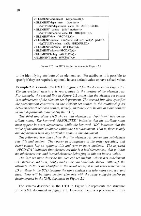
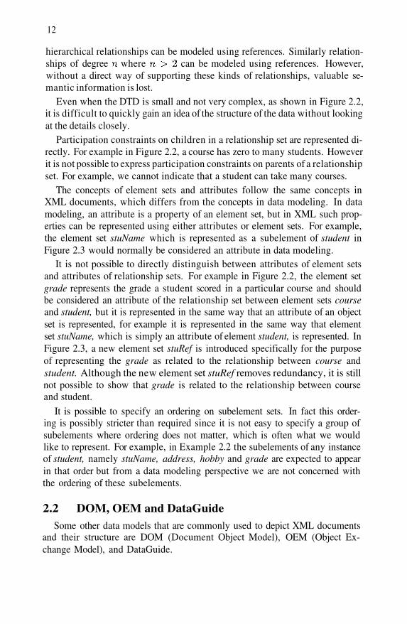
Figure 2.2. A DTD for the document in Figure 2.1
to the identifying attribute of an element set. For attributes it is possible tospecify if they are required, optional, have a default value or have a fixed value.
Example 2.2 Consider the DTD in Figure 2.2 for the document in Figure 2.1.The hierarchical structure is represented in the nesting of the element sets.For example, the second line in Figure 2.2 states that the element set courseis a subelement of the element set department. The second line also specifiesthe participation constraint on the element set course in the relationship setbetween department and course, namely, that there can be one or more coursesin each department (indicated by the “+ ”).
The third line of the DTD shows that element set department has an at-tribute name. The keyword “#REQUIRED” indicates that the attribute namemust appear in every department, while the keyword “ID” indicates that thevalue of the attribute is unique within the XML document. That is, there is onlyone department with any particular name in this document.
The following two lines show that the element set course has subelementsets title and student. They occur as a sequence in the order specified, andevery course has an optional title and zero or more students. The keyword“#PCDATA” indicates that element set title is a leaf element set, that is it hasno subelement sets and instead elements belonging to this set have a value.
The last six lines describe the element set student, which has subelementsets stuName, address, hobby and grade, and attribute stuNo. Although theattribute stuNo is an identifier in the usual sense, it is not represented as anID attribute in the DTD because the same student can take many courses, andthus, there will be many student elements with the same value for stuNo asdemonstrated in the XML document in Figure 2.1.
The schema described in the DTD in Figure 2.2 represents the structureof the XML document in Figure 2.1. However, there is a problem with this
Data Models for Semistructured Data 11
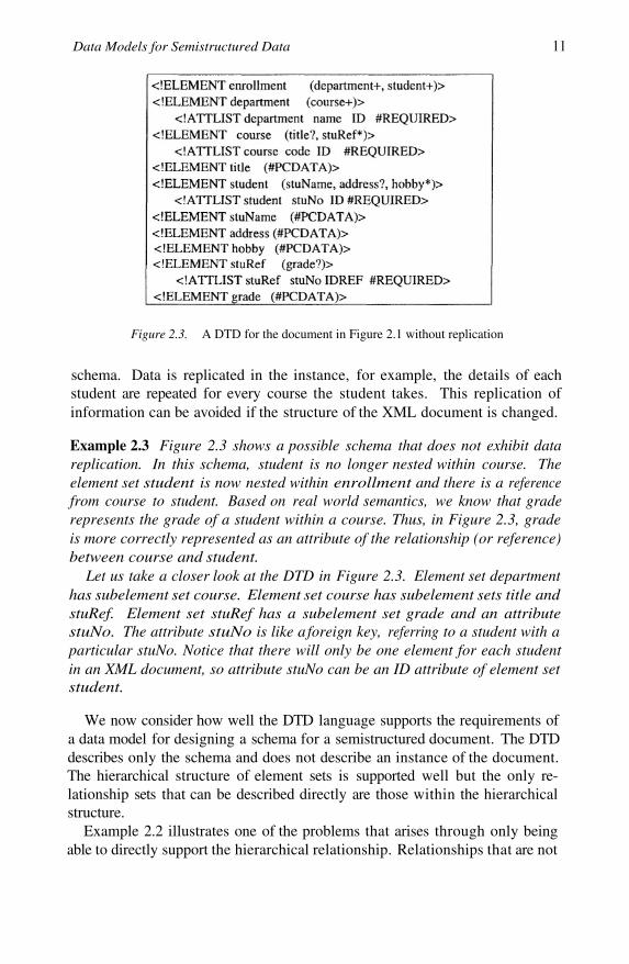
Figure 2.3. A DTD for the document in Figure 2.1 without replication
schema. Data is replicated in the instance, for example, the details of eachstudent are repeated for every course the student takes. This replication ofinformation can be avoided if the structure of the XML document is changed.
Example 2.3 Figure 2.3 shows a possible schema that does not exhibit datareplication. In this schema, student is no longer nested within course. Theelement set student is now nested within enrollment and there is a referencefrom course to student. Based on real world semantics, we know that graderepresents the grade of a student within a course. Thus, in Figure 2.3, gradeis more correctly represented as an attribute of the relationship (or reference)between course and student.
Let us take a closer look at the DTD in Figure 2.3. Element set departmenthas subelement set course. Element set course has subelement sets title andstuRef. Element set stuRef has a subelement set grade and an attributestuNo. The attribute stuNo is like a foreign key, referring to a student with aparticular stuNo. Notice that there will only be one element for each studentin an XML document, so attribute stuNo can be an ID attribute of element setstudent.
We now consider how well the DTD language supports the requirements ofa data model for designing a schema for a semistructured document. The DTDdescribes only the schema and does not describe an instance of the document.The hierarchical structure of element sets is supported well but the only re-lationship sets that can be described directly are those within the hierarchicalstructure.
Example 2.2 illustrates one of the problems that arises through only beingable to directly support the hierarchical relationship. Relationships that are not
12
hierarchical relationships can be modeled using references. Similarly relation-ships of degree where can be modeled using references. However,without a direct way of supporting these kinds of relationships, valuable se-mantic information is lost.
Even when the DTD is small and not very complex, as shown in Figure 2.2,it is difficult to quickly gain an idea of the structure of the data without lookingat the details closely.
Participation constraints on children in a relationship set are represented di-rectly. For example in Figure 2.2, a course has zero to many students. Howeverit is not possible to express participation constraints on parents of a relationshipset. For example, we cannot indicate that a student can take many courses.
The concepts of element sets and attributes follow the same concepts inXML documents, which differs from the concepts in data modeling. In datamodeling, an attribute is a property of an element set, but in XML such prop-erties can be represented using either attributes or element sets. For example,the element set stuName which is represented as a subelement of student inFigure 2.3 would normally be considered an attribute in data modeling.
It is not possible to directly distinguish between attributes of element setsand attributes of relationship sets. For example in Figure 2.2, the element setgrade represents the grade a student scored in a particular course and shouldbe considered an attribute of the relationship set between element sets courseand student, but it is represented in the same way that an attribute of an objectset is represented, for example it is represented in the same way that elementset stuName, which is simply an attribute of element student, is represented. InFigure 2.3, a new element set stuRef is introduced specifically for the purposeof representing the grade as related to the relationship between course andstudent. Although the new element set stuRef removes redundancy, it is stillnot possible to show that grade is related to the relationship between courseand student.
It is possible to specify an ordering on subelement sets. In fact this order-ing is possibly stricter than required since it is not easy to specify a group ofsubelements where ordering does not matter, which is often what we wouldlike to represent. For example, in Example 2.2 the subelements of any instanceof student, namely stuName, address, hobby and grade are expected to appearin that order but from a data modeling perspective we are not concerned withthe ordering of these subelements.
2.2 DOM, OEM and DataGuideSome other data models that are commonly used to depict XML documents
and their structure are DOM (Document Object Model), OEM (Object Ex-change Model), and DataGuide.
Data Models for Semistructured Data 13
Document Object ModelThe DOM (Document Object Model) [Apparao and Byrne, 1998] depicts
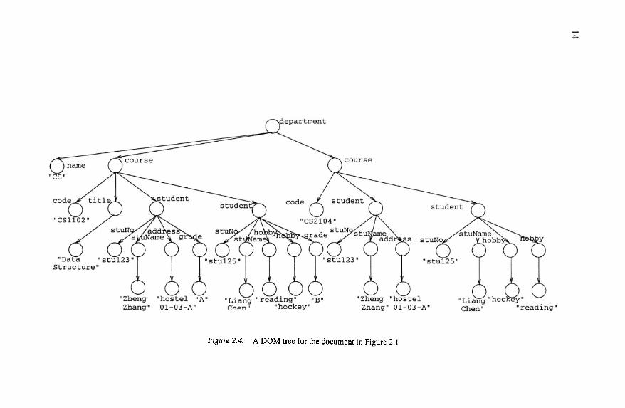
the instance of an XML document as a tree. Each node represents an objectthat contains one of the components from an XML structure. The three mostcommon type nodes are element nodes, attribute nodes and text nodes.
As illustrated in Figure 2.4, text nodes have no name but carry text (e.g.the text node with text “Data Structure”); attribute nodes have both a nameand carry text (e.g. the attribute node with attribute name name and text value“CS”); and element nodes have a name and may have children (e.g. the ele-ment node with element name course). The edges between nodes represent therelationships between the nodes.
How well does the DOM support the requirements of a data model for de-signing a schema for a semistructured document? A DOM tree represents theinstance of a document, showing the hierarchical structure of the elements, andthe implicit relationships between the elements due to the hierarchical struc-ture. It is possible to distinguish between attributes and elements. However,because the DOM represents an instance of an XML document, it does not rep-resent schema information directly, such as the degree of relationship sets, andparticipation constraints on element sets in relationship sets. For the same rea-son it is not possible to distinguish between ordered elements and unorderedelements, or whether an attribute belongs to a relationship set or an elementset.
Object Exchange ModelThe Object Exchange Model (OEM) [McHugh et al., 1997] also depicts
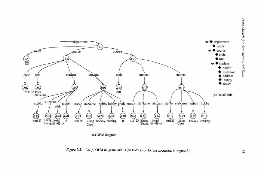
the contents of an XML document. An OEM model is a labeled directed graphwhere the vertices are objects, and the edges are relationships. Figure 2.5(a)shows the OEM model for the XML document in Figure 2.1.
Each object has a unique object identifier (OID), a label and a value. Thereare two types of objects, atomic and complex. Both atomic and complex ob-jects are depicted as 3-tuples: (OID, label, value). An atomic object containsa value from one of the disjoint basic atomic types, e.g., integers, real, string,etc. A complex object is a composition of objects where the value of a complexobject is a set of object references, denoted as a set of (label, OID) pairs. Weillustrate these concepts in Example 2.4.
Example 2.4 Consider the OEM model in Figure 2.5(a). The leaf nodes of thegraph are the atomic objects and the internal nodes are the complex objects.The complex object with object identifier &1 and name department is specifiedin the 3-tuple:
(&1, department, {(name, &2), (course, &4), (course, &5)}),where the set of tuples represent the objects that object &1 references.
14
Data M
odels for Semistructured D
ata15

16
The three atomic objects with object identifiers &27, &28 and &31 are spec-ified in the following three 3-tuples respectively showing their OID, name andvalue:
(&27, stuNo, stu125)(&28, stuName, Liang Chen)(&31, grade, B)
An OEM indicates the hierarchical structure of the objects. Although ithas both the diagrammatic and textual representation, not only does it havethe same shortcomings as the DOM but it also suffers from not distinguishingbetween elements and attributes.
DataGuideA DataGuide [Goldman and Widom, 1997] models the schema of an OEM
instance graph, depicting every path through the instance only once. Figure2.5 shows the OEM model and its DataGuide for the XML document in Figure2.1. From the DataGuide, it is easy to see that instances of the element setsdepartment, course and student are complex objects (depicted by a triangle),where an instance of the element set department is composed of the atomic ob-ject name, and the multiple occurrence complex object course, where instancesof the element set course in turn are composed of the atomic objects code andtitle, and the multiple occurrence complex object student.
How well does OEM with DataGuides support the requirements of a datamodel for designing a schema for a semistructured document? From this ex-ample, you can see that a DataGuide depicts only the hierarchical structure ofthe element sets and like the OEM it does not distinguish between element setsand attributes. It is in fact less expressive than the DTD since it is not possibleto represent the participation constraints on element sets in relationship sets,and because there is no distinction between element sets and attributes it is notpossible to represent the constraints on attributes that can be modeled in theDTD. It is not possible to represent references using OEM and DataGuides,which means it is not possible to model ID, IDREF and IDREFS from theDTD.
2.3 S3-graphA Semi-Structured Schema Graph (S3-Graph) is a directed graph where
each node in the graph can be classified into an entity node or a referencenode. An entity node represents an entity which can be of basic atomic datatype such as string, date or complex object type such as student. The former isalso known as a leaf entity node. A reference node is a node which referencesto another entity node.
Data Models for Semistructured Data 17
Each directed edge in the graph is associated with a tag. The tag representsthe relationship between the source node and the destination node. The tagmay be suffixed with a “*”. The interpretations of tag and the suffix depend onthe type of edge. There are three types of edges:
Component Edge
A node is connected to another node via a component edge with a tagT if is a component of This edge is denoted by a solid arrow line. IfT is suffixed with a “*”, the relationship is interpreted as “The entity typerepresented by has many T”. Otherwise, the relationship is interpretedas “The entity type represented by has at most one T”.
1
2 Referencing Edge
A node is connected to another node via a referencing edge ifreferences the entity represented by node This type of edge is denotedby a dashed arrow line.
3 Root Edge
A node is pointed to by a root edge with a tag T if the entity typerepresented by is owned by the database. This edge is denoted by asolid arrow line without any source node for the edge, and there is no suffixfor the tag T. In fact, is a root node in the S3-Graph.
Some roles R can be associated with a node V if there is a directed (compo-nent or referencing) edge pointing to V with tag R after removing any suffix“*”.
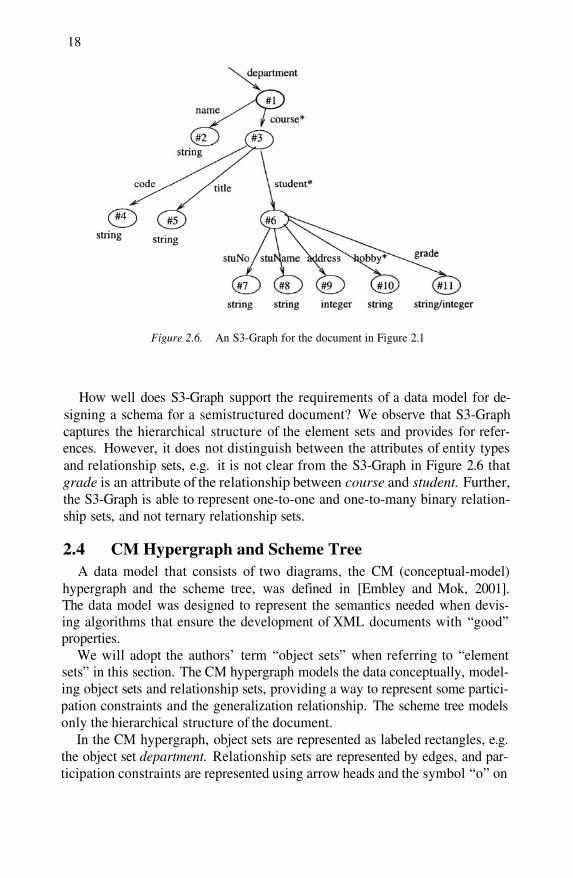
Example 2.5 Figure 2.6 shows the S3-Graph for the XML document in Fig-ure 2.1. Node #1 represents an entity node, which represents the entity DE-PARTMENT. This is also a root node. This node is associated with the role“department”.
Node #2 is another entity node of which database instance holds a stringrepresenting the NAME of a department. It is associated with the role “name ”,and it is also a leaf node associated the atomic data type “string”. Hence, any“NAME” data is of string type. The directed edge between node #1 and node#2 represents “Each DEPARTMENT has at most one NAME”.
Nodes #3 and #6 are entity nodes which represents the entities COURSEand STUDENT which are complex object types. A complex object type such asCOURSE is connected to leaf entity nodes #4 and #5 that are associated withthe roles “code” and “title” respectively.
Note that the tag on the edge from node #1 to node #3 is suffixed with a“*”. Hence, the relationship is interpreted as “A DEPARTMENT has manyCOURSE”.
18
Figure 2.6. An S3-Graph for the document in Figure 2.1
How well does S3-Graph support the requirements of a data model for de-signing a schema for a semistructured document? We observe that S3-Graphcaptures the hierarchical structure of the element sets and provides for refer-ences. However, it does not distinguish between the attributes of entity typesand relationship sets, e.g. it is not clear from the S3-Graph in Figure 2.6 thatgrade is an attribute of the relationship between course and student. Further,the S3-Graph is able to represent one-to-one and one-to-many binary relation-ship sets, and not ternary relationship sets.
2.4 CM Hypergraph and Scheme TreeA data model that consists of two diagrams, the CM (conceptual-model)
hypergraph and the scheme tree, was defined in [Embley and Mok, 2001].The data model was designed to represent the semantics needed when devis-ing algorithms that ensure the development of XML documents with “good”properties.
We will adopt the authors’ term “object sets” when referring to “elementsets” in this section. The CM hypergraph models the data conceptually, model-ing object sets and relationship sets, providing a way to represent some partici-pation constraints and the generalization relationship. The scheme tree modelsonly the hierarchical structure of the document.
In the CM hypergraph, object sets are represented as labeled rectangles, e.g.the object set department. Relationship sets are represented by edges, and par-ticipation constraints are represented using arrow heads and the symbol “o” on
Data Models for Semistructured Data 19
the edges. An edge with no arrow heads represents a many-to-many relation-ship set, an edge with one arrow head represents a many-to-one relationship,and an edge with an arrow head at both ends represents a one-to-one relation-ship. The symbol “o” indicates that an object is optional.
Another way to view the arrow head notation is as representing functionaldependencies. From the arrow heads, we can derive that code title and thatstuNo {name, address}.
The scheme tree represents the same information that a DataGuide repre-sents, namely the hierarchical structure of the object sets. The edges representthe element-subelement relationship. An algorithm that generates the schemetree from the CM hypergraph is described in [Embley and Mok, 2001]. Be-cause the CM hypergraph is more expressive than the scheme tree, it is notpossible to regenerate the CM hypergraph from the scheme tree.
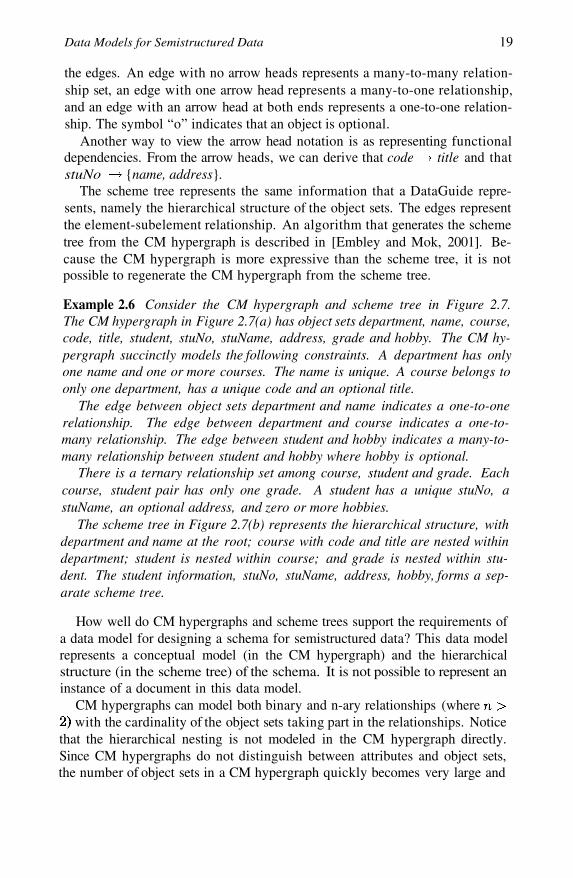
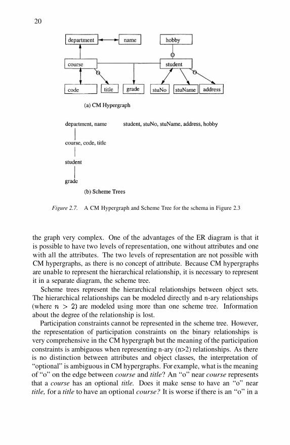
Example 2.6 Consider the CM hypergraph and scheme tree in Figure 2.7.The CM hypergraph in Figure 2.7(a) has object sets department, name, course,code, title, student, stuNo, stuName, address, grade and hobby. The CM hy-pergraph succinctly models the following constraints. A department has onlyone name and one or more courses. The name is unique. A course belongs toonly one department, has a unique code and an optional title.
The edge between object sets department and name indicates a one-to-onerelationship. The edge between department and course indicates a one-to-many relationship. The edge between student and hobby indicates a many-to-many relationship between student and hobby where hobby is optional.
There is a ternary relationship set among course, student and grade. Eachcourse, student pair has only one grade. A student has a unique stuNo, astuName, an optional address, and zero or more hobbies.
The scheme tree in Figure 2.7(b) represents the hierarchical structure, withdepartment and name at the root; course with code and title are nested withindepartment; student is nested within course; and grade is nested within stu-dent. The student information, stuNo, stuName, address, hobby, forms a sep-arate scheme tree.
How well do CM hypergraphs and scheme trees support the requirements ofa data model for designing a schema for semistructured data? This data modelrepresents a conceptual model (in the CM hypergraph) and the hierarchicalstructure (in the scheme tree) of the schema. It is not possible to represent aninstance of a document in this data model.
CM hypergraphs can model both binary and n-ary relationships (wherewith the cardinality of the object sets taking part in the relationships. Notice
that the hierarchical nesting is not modeled in the CM hypergraph directly.Since CM hypergraphs do not distinguish between attributes and object sets,the number of object sets in a CM hypergraph quickly becomes very large and
20
Figure 2.7. A CM Hypergraph and Scheme Tree for the schema in Figure 2.3
the graph very complex. One of the advantages of the ER diagram is that itis possible to have two levels of representation, one without attributes and onewith all the attributes. The two levels of representation are not possible withCM hypergraphs, as there is no concept of attribute. Because CM hypergraphsare unable to represent the hierarchical relationship, it is necessary to representit in a separate diagram, the scheme tree.
Scheme trees represent the hierarchical relationships between object sets.The hierarchical relationships can be modeled directly and n-ary relationships(where are modeled using more than one scheme tree. Informationabout the degree of the relationship is lost.
Participation constraints cannot be represented in the scheme tree. However,the representation of participation constraints on the binary relationships isvery comprehensive in the CM hypergraph but the meaning of the participationconstraints is ambiguous when representing n-ary (n>2) relationships. As thereis no distinction between attributes and object classes, the interpretation of“optional” is ambiguous in CM hypergraphs. For example, what is the meaningof “o” on the edge between course and title? An “o” near course representsthat a course has an optional title. Does it make sense to have an “o” neartitle, for a title to have an optional course? It is worse if there is an “o” in a
Data Models for Semistructured Data 21
ternary relationship, such as an “o” near course, on the edge between courseand student. How do we represent that a student is taking a course but doesnot have a grade yet?
It is not possible to represent any form of ordering on object sets, for exam-ple it is not possible to represent that there is an ordering on students within acourse.
2.5 EER and XGrammarA language and diagram for modeling XML schemas was defined in [Mani
et al., 2001]. The language, called XGrammar, was designed with the aim ofcapturing the most important features of the proposed XML schema languages.The diagram called the Extended Entity Relationship diagram (EER), differsfrom other EER diagram notations in that it captures all the concepts that canbe represented in Entity Relationship (ER) diagrams while also capturing thehierarchical relationship and ordering on element sets.
The hierarchical relationship or element-subelement relationship is repre-sented using a dummy relationship set labeled “has”. The ordering on elementsis expressed as a solid line between the relationship set and the ordered entityset. The authors use the term “entity sets” when referring to “element sets”.Entity sets are represented as rectangles and relationship sets by diamonds onthe edges.
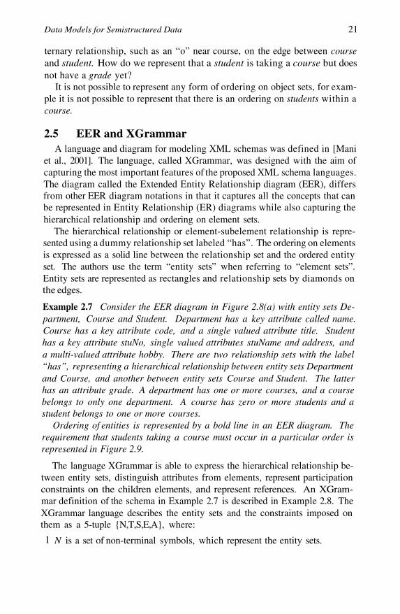
Example 2.7 Consider the EER diagram in Figure 2.8(a) with entity sets De-partment, Course and Student. Department has a key attribute called name.Course has a key attribute code, and a single valued attribute title. Studenthas a key attribute stuNo, single valued attributes stuName and address, anda multi-valued attribute hobby. There are two relationship sets with the label“has”, representing a hierarchical relationship between entity sets Departmentand Course, and another between entity sets Course and Student. The latterhas an attribute grade. A department has one or more courses, and a coursebelongs to only one department. A course has zero or more students and astudent belongs to one or more courses.
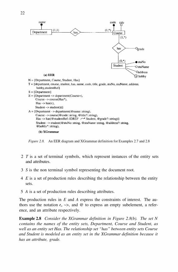
Ordering of entities is represented by a bold line in an EER diagram. Therequirement that students taking a course must occur in a particular order isrepresented in Figure 2.9.
The language XGrammar is able to express the hierarchical relationship be-tween entity sets, distinguish attributes from elements, represent participationconstraints on the children elements, and represent references. An XGram-mar definition of the schema in Example 2.7 is described in Example 2.8. TheXGrammar language describes the entity sets and the constraints imposed onthem as a 5-tuple {N,T,S,E,A}, where:
1 N is a set of non-terminal symbols, which represent the entity sets.
22
Figure 2.8. An EER diagram and XGrammar definition for Examples 2.7 and 2.8
T is a set of terminal symbols, which represent instances of the entity setsand attributes.
S is the non terminal symbol representing the document root.
E is a set of production rules describing the relationship between the entitysets.
A is a set of production rules describing attributes.
2
3
4
5
The production rules in E and A express the constraints of interest. The au-thors use the notation ~>, and @ to express an empty subelement, a refer-ence, and an attribute respectively.
Example 2.8 Consider the XGrammar definition in Figure 2.8(b). The set Ncontains the names of the entity sets, Department, Course and Student, aswell as an entity set Has. The relationship set “has” between entity sets Courseand Student is modeled as an entity set in the XGrammar definition because ithas an attribute, grade.
Data Models for Semistructured Data 23
Figure 2.9. An EER diagram and XGrammar definition representing ordering on studentwithin course
Just as in relational data modeling where many-to-many relationships withan attribute are captured in a separate relation, XGrammar models many-to-many relationships with an attribute as a separate entity set. The other “has”relationship set between Department and Course is a one-to-many relationshipand is captured in the nesting of Course within Department. The set T containsthe entities and attributes. S contains the entity set that is the root of the tree.
The set E specifies the relationship sets on the entity sets. The first rule inE specifies that entity set Department has one or more Courses. Recall theDepartment represents the entity set while department represents an entity orinstance of Department. The second rule specifies that and entity belonging tothe entity set Course has zero or more entities of the entity set Has as subele-ments. The third and fourth rules specify that the entity sets Has and Studenthave no children. This is represented by the
As mentioned above, we have included the entity set Has in the XGram-mar definition to deal with the relationship attribute grade. The constraintson attributes are described in set A. An @ denotes an attribute. Entity setDepartment has an attribute name which is of type string. Entity set Coursehas two attributes code, and title which is optional. Entity set Has has at-tributes studentRef which is a reference to Student denoted by ~>, and gradewhich is optional. Entity set Student has attributes stuNo, stuName, addresswhich is optional, and hobby which is a multi-valued attribute.
How well does the EER and XGrammar support the requirements of a datamodel for designing a schema for semistructured data? The EER diagram andXGrammar serve different purposes and can in turn represent different con-cepts. It is not possible to represent an instance of an XML document usingEER or XGrammar. In an EER diagram it is not possible to represent whichentity set is the root of the tree. There is a problem with representing thehierarchical structure of a semistructured schema in the EER diagram. Therelationship set “has” is used to express the hierarchical structure, but this rela-tionship set has no direction so it is unclear which entity set is the element andwhich is the subelement in the relationship set. So the relationship set “has”
24
cannot represent the hierarchical structure directly. As shown in Figure 2.8(a)there can be more than one “has” relationship types in an EER diagram.
The hierarchical structure can be represented in XGrammar, but like theDTD, XGrammar represents the hierarchical structure as a binary relationshiponly. It is possible to represent n-ary as well as binary relationships in the EERdiagram but because n-ary relationships were not considered in [Mani et al.,2001], the authors have not considered any implications of these relationshipsin the algorithms that they specify. It is possible to represent the participationconstraints of both child and parent entity sets in the EER diagram, but notin XGrammar. It is possible to show that an attribute is a key or identifyingattribute in the EER diagram but it is not possible to show whether other at-tributes are mandatory or optional. One way to overcome this problem is torepresent attributes as entity sets but this could lead to many more entity setsthan are really needed. It is not possible to represent identifying attributes inXGrammar.
Like in ER diagrams, it is possible to represent attributes of relationship setsin the EER diagram and there is also an extension to represent ordering on el-ements. However, there is no distinction between attributes of entity sets andattributes of relationship sets in XGrammar. Also, it is not possible to repre-sent ordering directly in XGrammar. It is not possible to represent orderingon attributes in EER diagrams or XGrammar, except to represent ordered at-tributes as elements. A distinction is made between attributes and elements inboth EER diagrams and XGrammar. The concept of attribute here is the sameas that in ER diagrams which differs from the concept in XML documents, sosome of the attributes in the EER diagram might be modeled as elements in anXML document.
From the examples and discussion, we can see that EER diagrams are bet-ter for conceptual modeling while the XGrammar language is more appropriatefor specifying the “implementation” details of the schema. For example in Fig-ure 2.8, information such as there is a many-to-many relationship set betweenentity sets Course and Student is lost in the XGrammar model. The factthat grade is an attribute of the relationship set between entity sets Courseand Student is also lost. These concepts are modeled using an entity set Hasand a reference, but the reason for modeling these concepts in this way are notrecorded in the XGrammar model.
2.6 AL-DTD and XML TreeArenas and Libkin describe a data model that they later use to define a nor-
mal form called XNF [Arenas and Libkin, 2004]. In the data model, they definelanguages for describing an XML Tree and a DTD. In this section we will referto the DTD defined by Arenas and Libkin as the AL-DTD to avoid confusion.

Data Models for Semistructured Data 25
Figure 2.10. A textual representation of the XML Tree in Figure 2.11
An XML Tree is defined precisely in a textual description which can beshown diagrammatically as a tree. The internal nodes are labeled with identi-fiers, and the leaf nodes are labeled with the value of an attribute or elementset.
The textual description is represented as T = (V, lab, ele, att, root) where:
V is the set of node identifiers,
lab is a mapping from the node identifiers to the names of the element setsand attributes,
ele is a mapping from the node identifiers to a list of node identitiers or astring,
att is a mapping from the node identifier and attribute name to the value ofthe attribute.
1
2
3
4
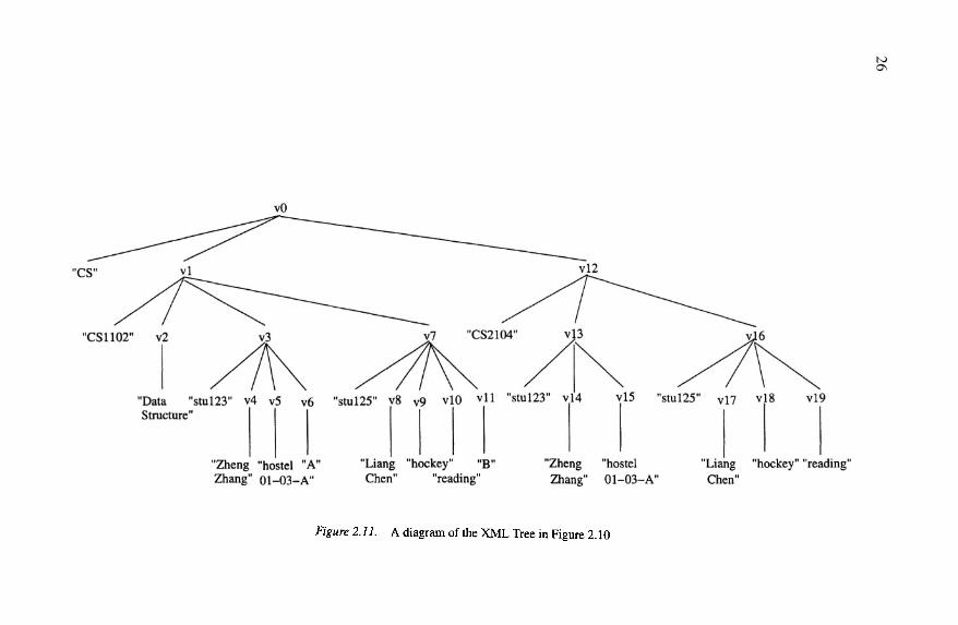
Example 2.9 Consider the XML Tree in text format in Figure 2.10 and thediagrammatic representation in Figure 2.11.
In the diagrammatic representation, identifiers are assigned to the internalnodes of the tree. These identifiers are in turn used in the textual representation
26
Data Models for Semistructured Data 27
of the document instance. V is the set of vertices, or node identifiers. Thelabels in the mapping lab correspond to the values of the tags in the originalXML document. These labels include department, course, title, etc. labprovides the mapping from node identifiers to labels.
The mapping ele maps from a node identifier to either a string value (e.g.= “Data Structures”) indicating that the node is a leaf node
or a list of node identifiers (e.g. indicating that the nodeis a non-leaf node with children and in this case).
The mapping att maps the node id and attribute name to the value of theattribute. For example, the mapping shows thatnode with id has an attribute called name with value “CS”.
One of the deficiencies of the textual representation is that it is difficult tovisualize the data and their relationships. The node identifiers in the diagram-matic representation and in V in the textual representation are introduced andbear no relationship to the original XML document. The diagrammatic rep-resentation alone also has a number of deficiencies. In particular, the labelsof nodes and attribute names are not shown; the relationships captured are bi-nary relationships; and it is not possible to distinguish between attributes ofelements and attributes of relationships, e.g. stuName and grade are repre-sented in the same way. Notice that the ordering of the children is significant.
The schema of the XML Tree, represented in an AL-DTD, can be repre-sented precisely in a language that captures similar semantics to the documenttype definition (DTD) language [Bray et al., 2000].
The AL-DTD is represented as D = (E, A, P, R, r) where:
E is a set of element sets,
A is a set of attributes,
P is a mapping from element sets to the children of the element sets, indi-cating the participation constraints on children,
R is a mapping from element sets to attributes, indicating which elementset the attribute belongs to,
r is the name of the root element set.
1
2
3
4
5
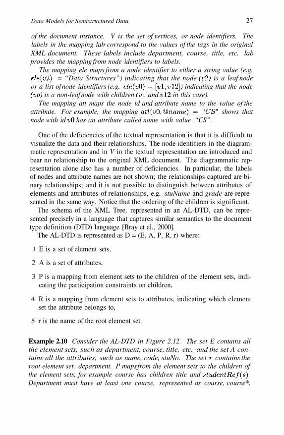
Example 2.10 Consider the AL-DTD in Figure 2.12. The set E contains allthe element sets, such as department, course, title, etc. and the set A con-tains all the attributes, such as name, code, stuNo. The set contains theroot element set, department. P maps from the element sets to the children ofthe element sets, for example course has children title andDepartment must have at least one course, represented as course, course*.
28
Figure 2.12. An AL-DTD schema for the XML Tree in Figures 2.10 and 2.11
An element set that has a string value is mapped to S, which corresponds toPCDATA in the DTD. R which is the mapping from element sets to attributesshows that element set department has attribute name etc.
How well does the AL-DTD and XML Tree support the requirements of adata model for designing a schema for semistructured data? This data modelis able to succinctly and precisely represent both the instance and schemas ofXML documents. However, since it is based on XML documents, it has thesame shortcomings as XML. While it handles hierarchical relationships nicely,it is not possible to represent many-to-many and many-to-one relationships.It is not possible to distinguish between binary and n-ary relation-ships and there is also no distinction between attributes of element sets andattributes of relationships. The AL-DTD does not show identifying attributes,and because the schema is modeled as a tree it is not possible to model IDREFor IDREFS from the DTD language directly. The AL-DTD is less expressivethan the DTD language.
2.7 ORA-SSThe ORA-SS data model [Dobbie et al., 2000] has four basic concepts: ob-
ject classes, relationship types, attributes and references, and consists of fourdiagrams: the schema diagram, the instance diagram, the functional depen-dency diagram and the inheritance diagram. Notice that “element sets” arecalled “object classes” in the ORA-SS data model, and “relationship sets” arecalled “relationship types”.
The ORA-SS instance diagram is like a DOM tree, in that it captures theinstance of a document. However, it is unlike the DOM tree in that it is possi-ble to distinguish between attributes and object classes. The ORA-SS schemadiagram, which captures the schema information, is like the CM hypergraph,except that it is semantically richer. The functional dependency diagram cap-tures functional dependencies that cannot be expressed in the participation con-
Data Models for Semistructured Data 29
straints in the schema diagram, such as those of n-ary relationships, and theinheritance diagram captures ISA relationships.
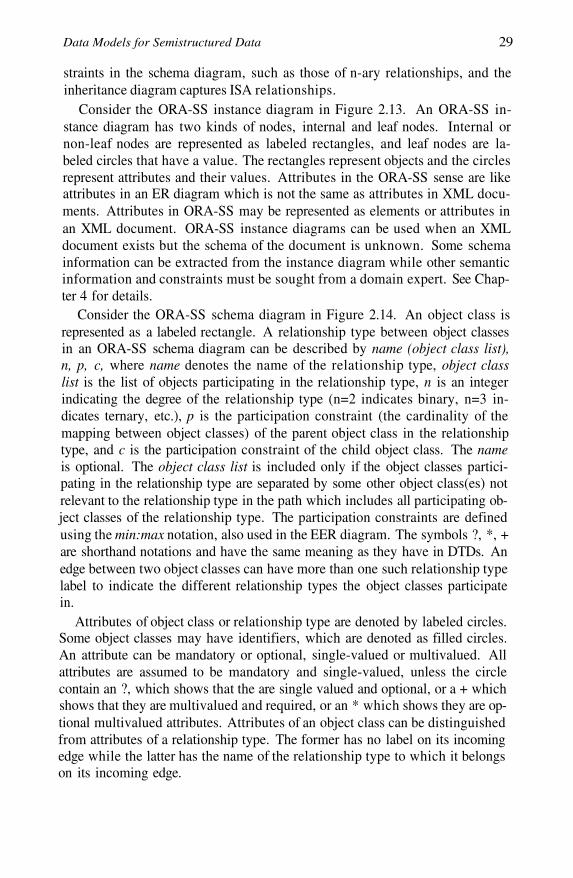
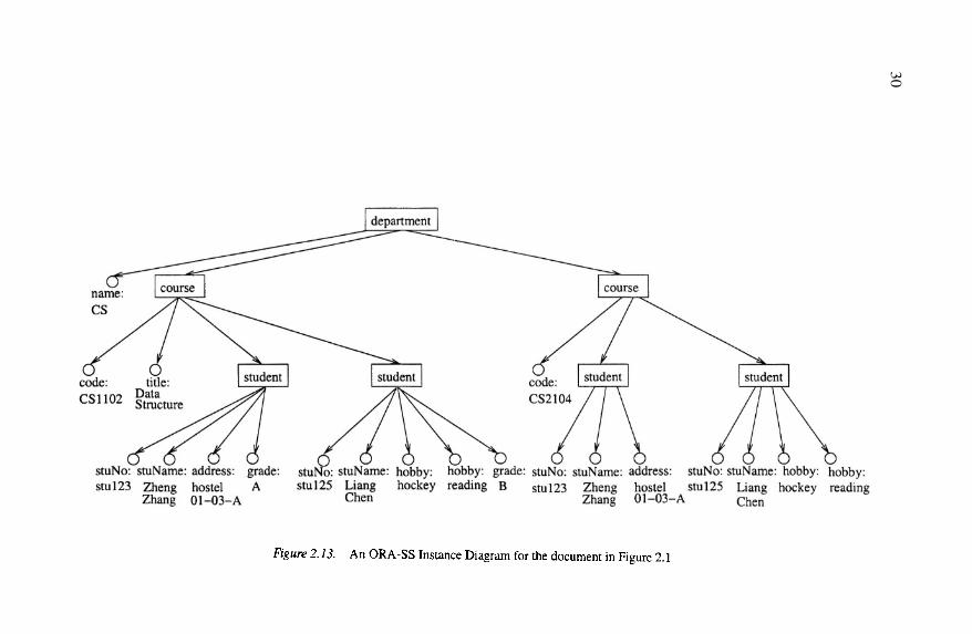
Consider the ORA-SS instance diagram in Figure 2.13. An ORA-SS in-stance diagram has two kinds of nodes, internal and leaf nodes. Internal ornon-leaf nodes are represented as labeled rectangles, and leaf nodes are la-beled circles that have a value. The rectangles represent objects and the circlesrepresent attributes and their values. Attributes in the ORA-SS sense are likeattributes in an ER diagram which is not the same as attributes in XML docu-ments. Attributes in ORA-SS may be represented as elements or attributes inan XML document. ORA-SS instance diagrams can be used when an XMLdocument exists but the schema of the document is unknown. Some schemainformation can be extracted from the instance diagram while other semanticinformation and constraints must be sought from a domain expert. See Chap-ter 4 for details.
Consider the ORA-SS schema diagram in Figure 2.14. An object class isrepresented as a labeled rectangle. A relationship type between object classesin an ORA-SS schema diagram can be described by name (object class list),n, p, c, where name denotes the name of the relationship type, object classlist is the list of objects participating in the relationship type, n is an integerindicating the degree of the relationship type (n=2 indicates binary, n=3 in-dicates ternary, etc.), p is the participation constraint (the cardinality of themapping between object classes) of the parent object class in the relationshiptype, and c is the participation constraint of the child object class. The nameis optional. The object class list is included only if the object classes partici-pating in the relationship type are separated by some other object class(es) notrelevant to the relationship type in the path which includes all participating ob-ject classes of the relationship type. The participation constraints are definedusing the min:max notation, also used in the EER diagram. The symbols ?, *, +are shorthand notations and have the same meaning as they have in DTDs. Anedge between two object classes can have more than one such relationship typelabel to indicate the different relationship types the object classes participatein.
Attributes of object class or relationship type are denoted by labeled circles.Some object classes may have identifiers, which are denoted as filled circles.An attribute can be mandatory or optional, single-valued or multivalued. Allattributes are assumed to be mandatory and single-valued, unless the circlecontain an ?, which shows that the are single valued and optional, or a + whichshows that they are multivalued and required, or an * which shows they are op-tional multivalued attributes. Attributes of an object class can be distinguishedfrom attributes of a relationship type. The former has no label on its incomingedge while the latter has the name of the relationship type to which it belongson its incoming edge.
30
Data Models for Semistructured Data 31
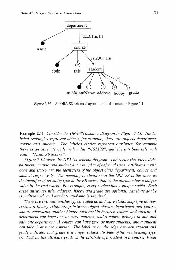
Figure 2.14. An ORA-SS schema diagram for the document in Figure 2.1
Example 2.11 Consider the ORA-SS instance diagram in Figure 2.13. The la-beled rectangles represent objects, for example, there are objects department,course and student. The labeled circles represent attributes, for examplethere is an attribute code with value “CS1102”, and the attribute title withvalue “Data Structure”.
Figure 2.14 show the ORA-SS schema diagram. The rectangles labeled de-partment, course and student are examples of object classes. Attributes name,code and stuNo are the identifiers of the object class department, course andstudent respectively. The meaning of identifier in the ORA-SS is the same asthe identifier of an entity type in the ER sense, that is, the attribute has a uniquevalue in the real world. For example, every student has a unique stuNo. Eachof the attributes title, address, hobby and grade are optional. Attribute hobbyis multivalued, and attribute stuName is required.
There are two relationship types, called dc and cs. Relationship type dc rep-resents a binary relationship between object classes department and course,and cs represents another binary relationship between course and student. Adepartment can have one or more courses, and a course belongs to one andonly one department. A course can have zero or more students, and a studentcan take 1 or more courses. The label cs on the edge between student andgrade indicates that grade is a single valued attribute of the relationship typecs. That is, the attribute grade is the attribute of a student in a course. From
32
these constraints, we can derive that
Some of the information in the label is redundant so it is not necessary toinclude all the fields. For example the label for relationship type dc can beshortened to 2,+,1:1, since we do not need to use the name of the relationshiptype elsewhere and it is obvious that the relationship type is between objectclasses department and course.
How well does the ORA-SS data model support the requirements of a datamodel for designing a schema for semistructured data? The hierarchical struc-ture of the object classes is clearly shown in the ORA-SS schema diagram,along with participation constraints on parent and children object classes. Adistinction is made between attributes of object classes and attributes of rela-tionship types. An attribute that belongs to a relationship type has the name ofthe relationship type on its incoming edge where an attribute that belongs toan object class has no label on its incoming edge. Compare for example theattributes address and grade. Attribute address is an attribute of student whereattribute grade is an attribute of the relationship type cs where the participatingobject classes are course and student. In Figure 2.14 we depict only binaryrelationships but it is also possible to represent n-ary relationship typesin ORA-SS schema diagrams.
Example 2.12 The ORA-SS schema diagram in Figure 2.15 shows a relation-ship type between student and course called sc. Attribute grade is an at-tribute of relationship type sc. The attribute grade models the grade that astudent gains in a course. There is a binary relationship type between courseand tutor called ct, with an attribute hours. The attribute hours models thehours a tutor spends on a course per week. Finally there is a relationship typecalled sct among object classes student, course and tutor. It is a ternary re-lationship. Attribute feedback, which belongs to relationship type sct, modelsthe feedback a tutor gets on a course from a student.
It is also possible to depict orderings on attributes or elements. For exampleif students are to be ordered within a course, this is depicted by a < in the label,and if hobbies are ordered by priority this is depicted by a < on the incomingedge as shown in Figure 2.16.
A more detailed description of the ORA-SS data model in given in Chap-ter 3.
2.8 DiscussionIn this chapter, we have listed the features that are required in XML data
models to support the design of schemas for XML documents. We have de-

Data Models for Semistructured Data 33
Figure 2.15. An ORA-SS schema diagram showing binary and ternary relationships
Figure 2.16. An ORA-SS schema diagram showing ordering of students and hobbies
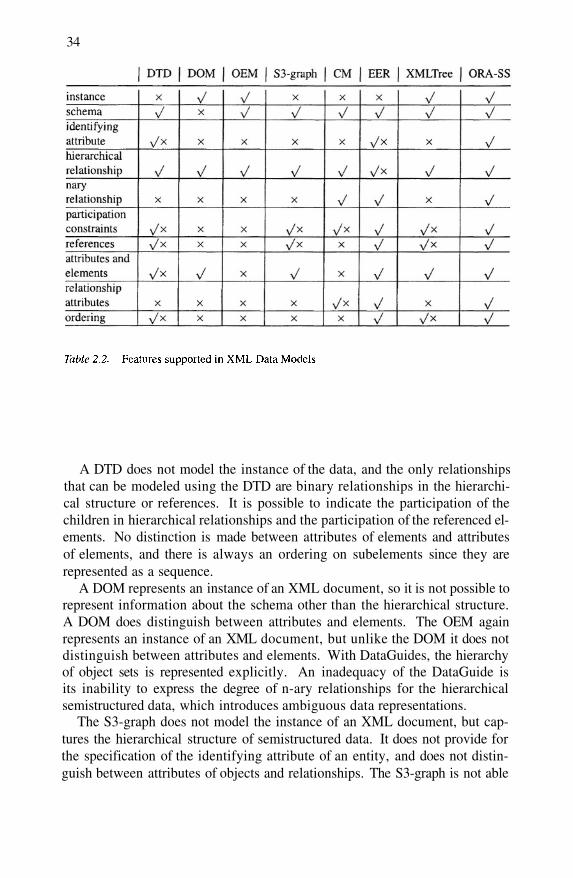
scribed the major data models that have been proposed for modeling schemasfor semistructured documents. Table 2.2 summarizes the findings of this chap-ter. In this table, a indicates the data model supports the feature, a × indi-cates that data model does not support the feature, while a indicates thatthe feature is partially supported or the feature is not directly supported but itis possible to model it.
34
A DTD does not model the instance of the data, and the only relationshipsthat can be modeled using the DTD are binary relationships in the hierarchi-cal structure or references. It is possible to indicate the participation of thechildren in hierarchical relationships and the participation of the referenced el-ements. No distinction is made between attributes of elements and attributesof elements, and there is always an ordering on subelements since they arerepresented as a sequence.
A DOM represents an instance of an XML document, so it is not possible torepresent information about the schema other than the hierarchical structure.A DOM does distinguish between attributes and elements. The OEM againrepresents an instance of an XML document, but unlike the DOM it does notdistinguish between attributes and elements. With DataGuides, the hierarchyof object sets is represented explicitly. An inadequacy of the DataGuide isits inability to express the degree of n-ary relationships for the hierarchicalsemistructured data, which introduces ambiguous data representations.
The S3-graph does not model the instance of an XML document, but cap-tures the hierarchical structure of semistructured data. It does not provide forthe specification of the identifying attribute of an entity, and does not distin-guish between attributes of objects and relationships. The S3-graph is not able
Data Models for Semistructured Data 35
to depict the degree of relationships, and cannot capture relationships beyondthe binary one-to-one and one-to-many relationships.
The CM hypergraph and scheme tree data model has no way to represent adata instance, does not provide a way to model references, does not distinguishbetween objects and attributes, has no way of representing ordering, and theconceptual information and nesting relationships are in two separate diagrams.Participation constraints and the distinction between attributes of relationshipsand attributes of elements can be modeled in CM hypergraphs.
Using the EER and the XGrammar data model it is not possible to representa data instance, and the representation of hierarchy in the EER diagram is am-biguous without other information. While it is possible to represent many ofthe other features, it is sometimes necessary to have both the EER represen-tation and the XGrammar representation to gain a clear understanding of theexact semantics. For example, if a relationship is modeled using referencesin the XGrammar representation then some participation constraint informa-tion is lost. Also, XGrammar does not distinguish between attributes of objectclasses and attributes of relationship types, and XGrammar is unable to repre-sent the degree of relationship types. Because it is not possible to model allthe constraints in either EER or XGrammar, both representations are requiredto model the semantics needed to effectively manage semistructured data.
The data model presented in [Arenas and Libkin, 2004] describes a languagefor specifying an instance, (i.e. the XML Tree), a diagram for representing theinstance and a language for specifying the schema (i.e. the AL-DTD). Thespecification of the instance, represents the hierarchical structure of the XMLinstance, the values of elements and attributes, and the ordering on elements.The language for specifying the schema captures most of the of the DTD lan-guage, except ID and IDREF(S). Consequently it is not possible to specify ann-ary relationship where it is not possible to specify the participationconstraint of a parent element in a relationship, and it is not possible to distin-guish between attributes of element sets and attributes of relationship types.
In summary, the major advantages of ORA-SS over existing semistructureddata models for designing schemas for semistructured data are its ability torepresent the data instance, distinguish between attributes and object classes,differentiate between attributes of object classes and attributes of relationshiptypes, and to express the degree of relationship types and the participation con-straints on the object classes in the relationship types. Such expressed informa-tion is important, even crucial for designing “good” semistructured databases,and defining meaningful semistructured views.

This page intentionally left blank
Chapter 3
ORA-SS
The ORA-SS data model has three basic concepts: object classes, relation-ship types and attributes. Object classes model sets of real world entities. Anobject class is related to other object classes through relationship types. At-tributes are properties, and may belong to an object class or a relationship type.The ORA-SS data model consists of four diagrams: ORA-SS instance dia-gram, ORA-SS schema diagram, functional dependency diagram and ORA-SSinheritance diagram. The instance diagram provides a way to visualize an in-stance of the data, the schema diagram represents the structure and constraintson an instance, additional functional dependencies can be represented in thefunctional dependency diagram and specialization/generalization relationshipsamong the object classes are represented in the inheritance diagram.
3.1 ORA-SS Schema DiagramAn ORA-SS schema diagram is a directed graph where each internal node
is an object class, and each leaf node is a complex attribute or an attribute. Thefocus of this section is to describe what can be expressed using the ORA-SSschema diagram. The various notations are summarized in Appendix A.
Object ClassAn object class represents a set of entities in the real world, and is similar
to an entity type in an ER diagram, a class in an object-oriented diagram orthe type of an element in the semistructured data model. An object class isrepresented by a labeled rectangle. The label shows the name of the object class(inside the rectangle). The name is mandatory. The attributes are representedas labeled circles joined to their object class by a directed edge and identifiersare filled circles. An identifier is a concept borrowed from the object oriented

38
Figure 3.1. Object class student with attributes in an ORA-SS Schema Diagram
model, where an identifier value can identify an object. Both attributes andidentifiers are described in more detail later in this chapter.
An entity type in an ER diagram typically has a name and is characterized bythe set of attributes that belong to each entity. Since semistructured data is lessregular than traditional (structured) data, the object classes are characterizedby a name rather than a set of attributes. The set of attributes associated withan object class are the attributes that instances of that object class could have.However, there is no expectation that every instance of an object class shouldhave a value for each attribute.
Example 3.1 Consider modeling a set of students where each student has astuNo, a name and might have an address. This is represented as an objectclass in Figure 3.1 by an object class student with identifier stuNo, and at-tributes name and address. The “?” indicates that the attribute address isoptional.
Relationship TypeTwo object classes are connected via a relationship type. A relationship type
in the ORA-SS data model represents a nesting relationship. Each relationshiptype has a degree and participation constraints. A relationship type of degree 2(i.e. a binary relationship type) relates two object classes. One object class isthe parent and the other the child, and we distinguish between the participationconstraint on the parent in the relationship type and the participation constrainton the child in the relationship type. A relationship type of degree 3 (i.e. aternary relationship) is a relationship type among three object classes.
In an ORA-SS schema diagram, a solid labeled directed edge connecting ob-ject classes represents a relationship type. A relationship type has a label of theform name(object class list), The label indicates a relation-ship type with name name, among objects in the object class list of degree
indicates binary, indicates ternary, etc.), where the participationof the parent has minimum and maximum and the participation of the childhas minimum and maximum The name is optional. The object class listis included only if the object classes participating in the relationship type areseparated by some other object class(es) not relevant to the relationship type in

ORA-SS 39
the path that contains all the participating object classes. By defining partici-pation constraints with min:max notation, we are able to represent numericalconstraints. The usual shorthand can also be used to represent the participationconstraints, ? represents 0 : 1 , * represents + represents Allfields in the label are optional. There is no default value for name. The defaultdegree is 2, default parent participation constraint is and default childparticipation constraint is
Example 3.2 The ORA-SS schema diagram in Figure 3.2(a) shows a binaryrelationship type, jm, between project and member and a binary relationshiptype, mp, between member and publication.
The relationship type between project and member is annotated with thelabel jm, 2, +, +, which represents a many-to-many binary relationship typebetween project and member, and a total participation constraint on bothobject classes. That is, each project has at least one member, and each mem-ber must participate in at least one project. The relationship type betweenmember and publication is a many-to-many binary relationship type. How-ever a member has zero to many publications, and each publication mustbelong to at least one member.
Figure 3.2(b) depicts an instance of this schema showing a relationshiptype between projects and members, and another between members andpublications, but no relationship type between projects and publications.This diagram indicates that member has publications pub1, pub2 andpub3, and works on projects and However, we do not know whichproject the publications are associated with. The DataGuide in Figure 3.2(c)illustrates how these relationships would typically be nested.
Example 3.3 In contrast, the ORA-SS schema diagram in Figure 3.3(a) showsa ternary relationship type between project, member and publication, rep-resenting the publications a member has for a particular project. There is abinary relationship type (named jm) between project and member, and arelationship type (named jmp) among project, member and publication.
Figure 3.3(b) depicts an instance of this schema, showing a relationshiptype between project and member, and another relationship type between theproject and member relationship type and publications. It is clear that pub-lications pub1 and pub2 are associated with member working on project
while publication pub3 is associated with member working on projectThe DataGuide in Figure 3.3(c) illustrates how these relationships would
typically be nested.
Note that the schema diagrams in Figure 3.2(a) and Figure 3.3(a) capturedifferent semantic information. Figure 3.2(a) captures information about who
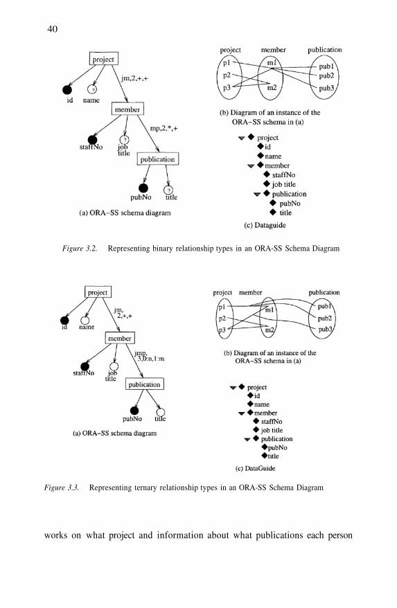
40
Figure 3.2. Representing binary relationship types in an ORA-SS Schema Diagram
Figure 3.3. Representing ternary relationship types in an ORA-SS Schema Diagram
works on what project and information about what publications each person
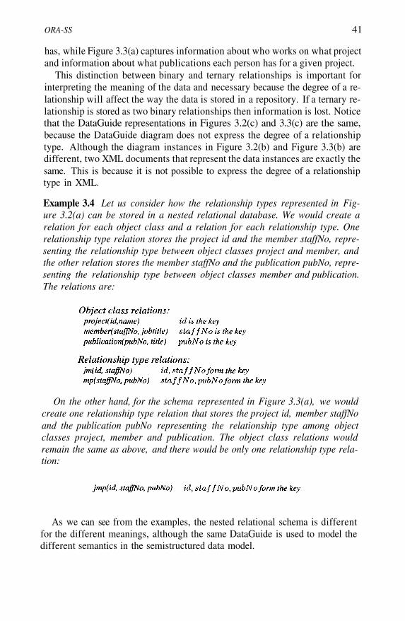
ORA-SS 41
has, while Figure 3.3(a) captures information about who works on what projectand information about what publications each person has for a given project.
This distinction between binary and ternary relationships is important forinterpreting the meaning of the data and necessary because the degree of a re-lationship will affect the way the data is stored in a repository. If a ternary re-lationship is stored as two binary relationships then information is lost. Noticethat the DataGuide representations in Figures 3.2(c) and 3.3(c) are the same,because the DataGuide diagram does not express the degree of a relationshiptype. Although the diagram instances in Figure 3.2(b) and Figure 3.3(b) aredifferent, two XML documents that represent the data instances are exactly thesame. This is because it is not possible to express the degree of a relationshiptype in XML.
Example 3.4 Let us consider how the relationship types represented in Fig-ure 3.2(a) can be stored in a nested relational database. We would create arelation for each object class and a relation for each relationship type. Onerelationship type relation stores the project id and the member staffNo, repre-senting the relationship type between object classes project and member, andthe other relation stores the member staffNo and the publication pubNo, repre-senting the relationship type between object classes member and publication.The relations are:
On the other hand, for the schema represented in Figure 3.3(a), we wouldcreate one relationship type relation that stores the project id, member staffNoand the publication pubNo representing the relationship type among objectclasses project, member and publication. The object class relations wouldremain the same as above, and there would be only one relationship type rela-tion:
As we can see from the examples, the nested relational schema is differentfor the different meanings, although the same DataGuide is used to model thedifferent semantics in the semistructured data model.
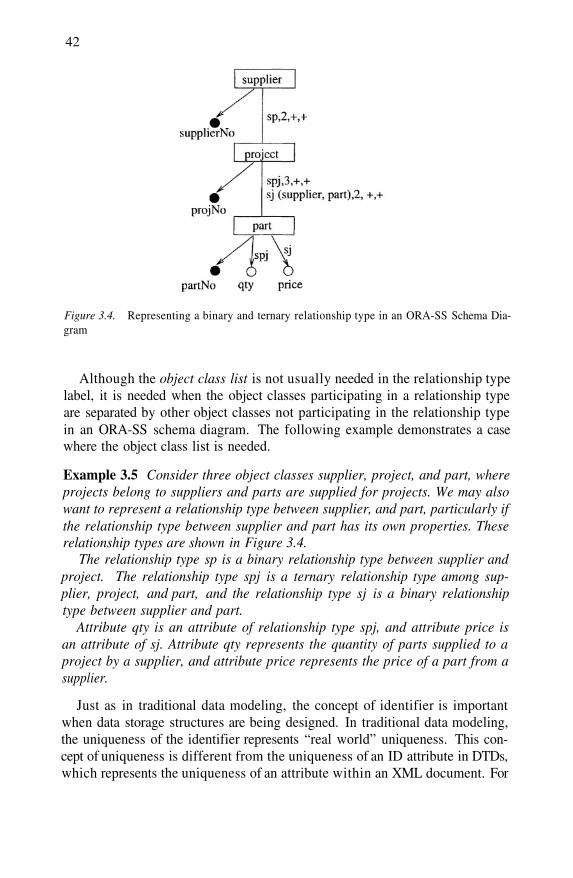
42
Figure 3.4. Representing a binary and ternary relationship type in an ORA-SS Schema Dia-gram
Although the object class list is not usually needed in the relationship typelabel, it is needed when the object classes participating in a relationship typeare separated by other object classes not participating in the relationship typein an ORA-SS schema diagram. The following example demonstrates a casewhere the object class list is needed.
Example 3.5 Consider three object classes supplier, project, and part, whereprojects belong to suppliers and parts are supplied for projects. We may alsowant to represent a relationship type between supplier, and part, particularly ifthe relationship type between supplier and part has its own properties. Theserelationship types are shown in Figure 3.4.
The relationship type sp is a binary relationship type between supplier andproject. The relationship type spj is a ternary relationship type among sup-plier, project, and part, and the relationship type sj is a binary relationshiptype between supplier and part.
Attribute qty is an attribute of relationship type spj, and attribute price isan attribute of sj. Attribute qty represents the quantity of parts supplied to aproject by a supplier, and attribute price represents the price of a part from asupplier.
Just as in traditional data modeling, the concept of identifier is importantwhen data storage structures are being designed. In traditional data modeling,the uniqueness of the identifier represents “real world” uniqueness. This con-cept of uniqueness is different from the uniqueness of an ID attribute in DTDs,which represents the uniqueness of an attribute within an XML document. For
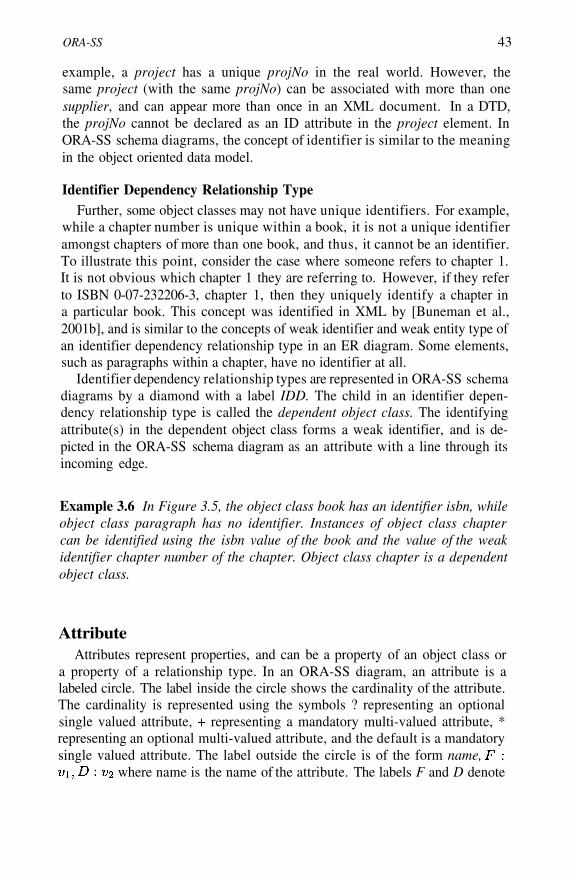
ORA-SS 43
example, a project has a unique projNo in the real world. However, thesame project (with the same projNo) can be associated with more than onesupplier, and can appear more than once in an XML document. In a DTD,the projNo cannot be declared as an ID attribute in the project element. InORA-SS schema diagrams, the concept of identifier is similar to the meaningin the object oriented data model.
Identifier Dependency Relationship TypeFurther, some object classes may not have unique identifiers. For example,
while a chapter number is unique within a book, it is not a unique identifieramongst chapters of more than one book, and thus, it cannot be an identifier.To illustrate this point, consider the case where someone refers to chapter 1.It is not obvious which chapter 1 they are referring to. However, if they referto ISBN 0-07-232206-3, chapter 1, then they uniquely identify a chapter ina particular book. This concept was identified in XML by [Buneman et al.,2001b], and is similar to the concepts of weak identifier and weak entity type ofan identifier dependency relationship type in an ER diagram. Some elements,such as paragraphs within a chapter, have no identifier at all.
Identifier dependency relationship types are represented in ORA-SS schemadiagrams by a diamond with a label IDD. The child in an identifier depen-dency relationship type is called the dependent object class. The identifyingattribute(s) in the dependent object class forms a weak identifier, and is de-picted in the ORA-SS schema diagram as an attribute with a line through itsincoming edge.
Example 3.6 In Figure 3.5, the object class book has an identifier isbn, whileobject class paragraph has no identifier. Instances of object class chaptercan be identified using the isbn value of the book and the value of the weakidentifier chapter number of the chapter. Object class chapter is a dependentobject class.
AttributeAttributes represent properties, and can be a property of an object class or
a property of a relationship type. In an ORA-SS diagram, an attribute is alabeled circle. The label inside the circle shows the cardinality of the attribute.The cardinality is represented using the symbols ? representing an optionalsingle valued attribute, + representing a mandatory multi-valued attribute, *representing an optional multi-valued attribute, and the default is a mandatorysingle valued attribute. The label outside the circle is of the form name,
where name is the name of the attribute. The labels F and D denote
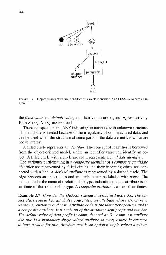
44
Figure 3.5. Object classes with no identifier or a weak identifier in an ORA-SS Schema Dia-gram
the fixed value and default value, and their values are and respectively.Both are optional.
There is a special name ANY indicating an attribute with unknown structure.This attribute is needed because of the irregularity of semistructured data, andcan be used when the structure of some parts of the data are not known or arenot of interest.
A filled circle represents an identifier. The concept of identifier is borrowedfrom the object oriented model, where an identifier value can identify an ob-ject. A filled circle with a circle around it represents a candidate identifier.The attributes participating in a composite identifier or a composite candidate
identifier are represented by filled circles and their incoming edges are con-nected with a line. A derived attribute is represented by a dashed circle. Theedge between an object class and an attribute can be labeled with name. Thename must be the name of a relationship type, indicating that the attribute is anattribute of that relationship type. A composite attribute is a tree of attributes.
Example 3.7 Consider the ORA-SS schema diagram in Figure 3.6. The ob-ject class course has attributes code, title, an attribute whose structure isunknown, currency and cost. Attribute code is the identifier of course and isa composite attribute. It is made up of the attributes dept pre fix and number.The default value of dept pre fix is comp, denoted as D : comp. An attributelike title is a mandatory single valued attribute so every course is expectedto have a value for title. Attribute cost is an optional single valued attribute
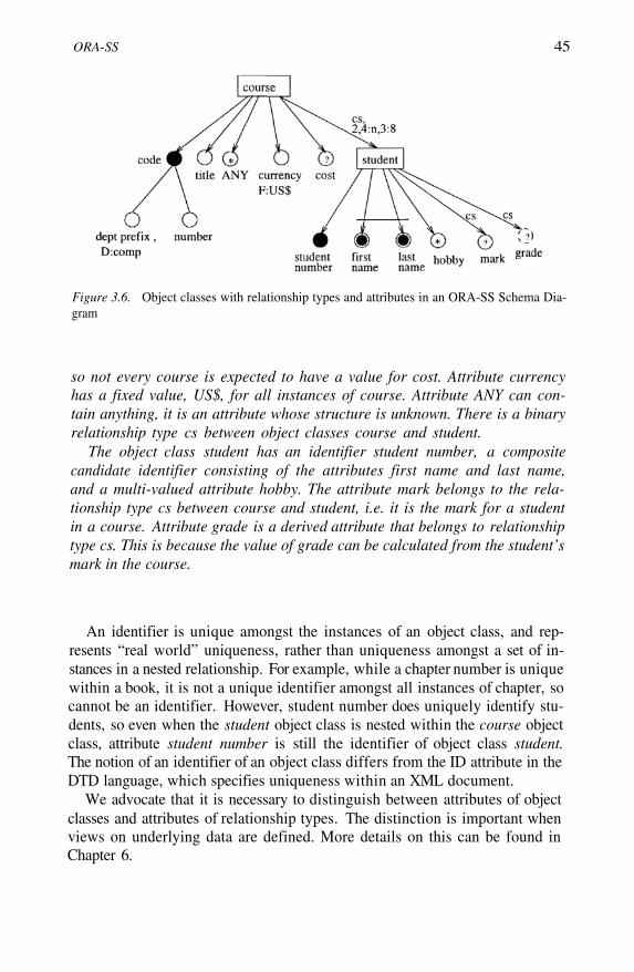
ORA-SS 45
Figure 3.6. Object classes with relationship types and attributes in an ORA-SS Schema Dia-gram
so not every course is expected to have a value for cost. Attribute currencyhas a fixed value, US$, for all instances of course. Attribute ANY can con-tain anything, it is an attribute whose structure is unknown. There is a binaryrelationship type cs between object classes course and student.
The object class student has an identifier student number, a compositecandidate identifier consisting of the attributes first name and last name,and a multi-valued attribute hobby. The attribute mark belongs to the rela-tionship type cs between course and student, i.e. it is the mark for a studentin a course. Attribute grade is a derived attribute that belongs to relationshiptype cs. This is because the value of grade can be calculated from the student’smark in the course.
An identifier is unique amongst the instances of an object class, and rep-resents “real world” uniqueness, rather than uniqueness amongst a set of in-stances in a nested relationship. For example, while a chapter number is uniquewithin a book, it is not a unique identifier amongst all instances of chapter, socannot be an identifier. However, student number does uniquely identify stu-dents, so even when the student object class is nested within the course objectclass, attribute student number is still the identifier of object class student.The notion of an identifier of an object class differs from the ID attribute in theDTD language, which specifies uniqueness within an XML document.
We advocate that it is necessary to distinguish between attributes of objectclasses and attributes of relationship types. The distinction is important whenviews on underlying data are defined. More details on this can be found inChapter 6.
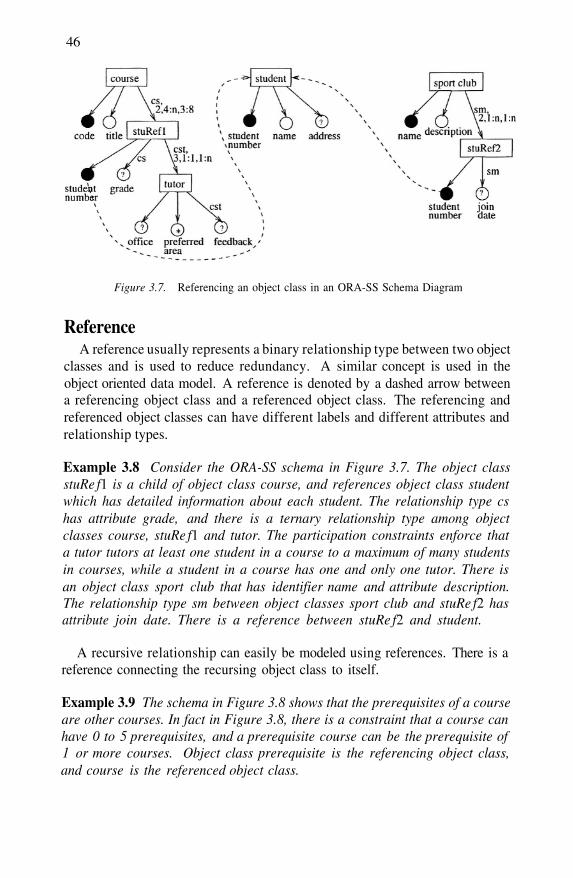
46
Figure 3.7. Referencing an object class in an ORA-SS Schema Diagram
ReferenceA reference usually represents a binary relationship type between two object
classes and is used to reduce redundancy. A similar concept is used in theobject oriented data model. A reference is denoted by a dashed arrow betweena referencing object class and a referenced object class. The referencing andreferenced object classes can have different labels and different attributes andrelationship types.
Example 3.8 Consider the ORA-SS schema in Figure 3.7. The object classstuRe f1 is a child of object class course, and references object class studentwhich has detailed information about each student. The relationship type cshas attribute grade, and there is a ternary relationship type among objectclasses course, stuRe f1 and tutor. The participation constraints enforce thata tutor tutors at least one student in a course to a maximum of many studentsin courses, while a student in a course has one and only one tutor. There isan object class sport club that has identifier name and attribute description.The relationship type sm between object classes sport club and stuRe f2 hasattribute join date. There is a reference between stuRe f2 and student.
A recursive relationship can easily be modeled using references. There is areference connecting the recursing object class to itself.
Example 3.9 The schema in Figure 3.8 shows that the prerequisites of a courseare other courses. In fact in Figure 3.8, there is a constraint that a course canhave 0 to 5 prerequisites, and a prerequisite course can be the prerequisite of1 or more courses. Object class prerequisite is the referencing object class,and course is the referenced object class.
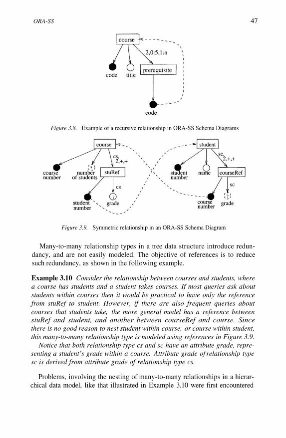
ORA-SS 47
Figure 3.8. Example of a recursive relationship in ORA-SS Schema Diagrams
Figure 3.9. Symmetric relationship in an ORA-SS Schema Diagram
Many-to-many relationship types in a tree data structure introduce redun-dancy, and are not easily modeled. The objective of references is to reducesuch redundancy, as shown in the following example.
Example 3.10 Consider the relationship between courses and students, wherea course has students and a student takes courses. If most queries ask aboutstudents within courses then it would be practical to have only the referencefrom stuRef to student. However, if there are also frequent queries aboutcourses that students take, the more general model has a reference betweenstuRef and student, and another between courseRef and course. Sincethere is no good reason to nest student within course, or course within student,this many-to-many relationship type is modeled using references in Figure 3.9.
Notice that both relationship type cs and sc have an attribute grade, repre-senting a student’s grade within a course. Attribute grade of relationship typesc is derived from attribute grade of relationship type cs.
Problems, involving the nesting of many-to-many relationships in a hierar-chical data model, like that illustrated in Example 3.10 were first encountered
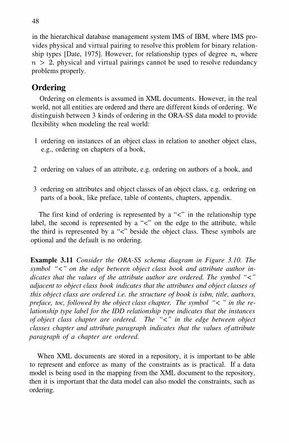
48
in the hierarchical database management system IMS of IBM, where IMS pro-vides physical and virtual pairing to resolve this problem for binary relation-ship types [Date, 1975]. However, for relationship types of degree where
physical and virtual pairings cannot be used to resolve redundancyproblems properly.
OrderingOrdering on elements is assumed in XML documents. However, in the real
world, not all entities are ordered and there are different kinds of ordering. Wedistinguish between 3 kinds of ordering in the ORA-SS data model to provideflexibility when modeling the real world:
ordering on instances of an object class in relation to another object class,e.g., ordering on chapters of a book,
ordering on values of an attribute, e.g. ordering on authors of a book, and
ordering on attributes and object classes of an object class, e.g. ordering onparts of a book, like preface, table of contents, chapters, appendix.
1
2
3
The first kind of ordering is represented by a “<” in the relationship typelabel, the second is represented by a “<” on the edge to the attribute, whilethe third is represented by a “<” beside the object class. These symbols areoptional and the default is no ordering.
Example 3.11 Consider the ORA-SS schema diagram in Figure 3.10. Thesymbol “<” on the edge between object class book and attribute author in-dicates that the values of the attribute author are ordered. The symbol “<”adjacent to object class book indicates that the attributes and object classes ofthis object class are ordered i.e. the structure of book is isbn, title, authors,preface, toc, followed by the object class chapter. The symbol “< ” in the re-lationship type label for the IDD relationship type indicates that the instancesof object class chapter are ordered. The “<” in the edge between objectclasses chapter and attribute paragraph indicates that the values of attributeparagraph of a chapter are ordered.
When XML documents are stored in a repository, it is important to be ableto represent and enforce as many of the constraints as is practical. If a datamodel is being used in the mapping from the XML document to the repository,then it is important that the data model can also model the constraints, such asordering.

ORA-SS 49
Figure 3.10. Ordered object classes, attributes, and attribute values in an ORA-SS SchemaDiagram
DisjunctionA characteristic of semistructured data is that attributes and object classes
are likely to be less homogeneous than in structured data. To allow for this, weprovide for two different kinds of disjunction in the ORA-SS data model:
disjunctive object classes, and
disjunctive attributes.
1
2
A disjunctive relationship is used to represent disjunctive object classes,such as a student lives in a hostel OR at home, and is represented by a relation-ship diamond labeled with symbol A disjunctive attribute is represented bya circle labeled with symbol with edges from this circle to the alternatives.
Example 3.12 Consider the schema diagram in Figure 3.11. A course hasa disjunctive attribute exam venue. Attribute exam venue is a disjunctivesingle-valued attribute, and can be a lecture theatre or a laboratory, butnot both. It is denoted by a inside a circle. Relationship sh is a disjunc-tive relationship, and is denoted by a inside a diamond. It represents thefact that a student can either live in a hostel or at home. The participationconstraints indicate that an instance of this relationship is mandatory, and astudent must have an address of either a hostel or home.
3.2 ORA-SS Data Instance DiagramTraditionally, when databases are designed, the schema is modeled using a
conceptual model and the schema of the database is derived from this model.
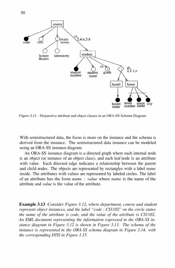
50
With semistructured data, the focus is more on the instance and the schema isderived from the instance. The semistructured data instance can be modeledusing an ORA-SS instance diagram.
An ORA-SS instance diagram is a directed graph where each internal nodeis an object (or instance of an object class), and each leaf node is an attributewith value. Each directed edge indicates a relationship between the parentand child nodes. The objects are represented by rectangles with a label nameinside. The attributes with values are represented by labeled circles. The labelof an attribute has the form name : value where name is the name of theattribute and value is the value of the attribute.
Example 3.13 Consider Figure 3.12, where department, course and studentrepresent object instances, and the label “code : CS1102” on the circle statesthe name of the attribute is code, and the value of the attribute is CS1102.An XML document representing the information expressed in the ORA-SS in-stance diagram in Figure 3.12 is shown in Figure 3.13. The schema of theinstance is represented in the ORA-SS schema diagram in Figure 3.14, withthe corresponding DTD in Figure 3.15.
Figure 3.11. Disjunctive attribute and object classes in an ORA-SS Schema Diagram

OR
A-SS
51
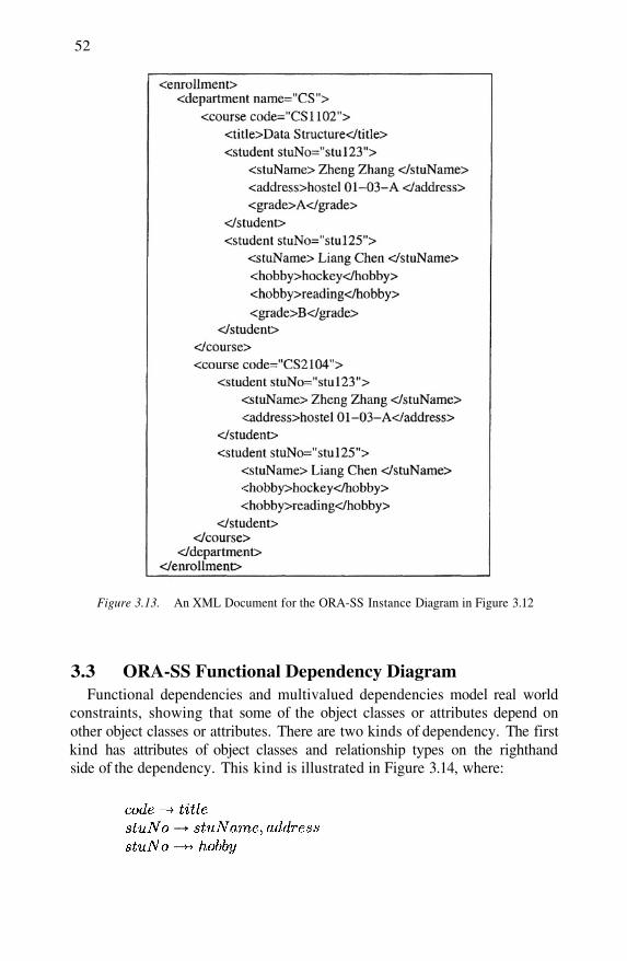
52
Figure 3.13. An XML Document for the ORA-SS Instance Diagram in Figure 3.12
3.3 ORA-SS Functional Dependency DiagramFunctional dependencies and multivalued dependencies model real world
constraints, showing that some of the object classes or attributes depend onother object classes or attributes. There are two kinds of dependency. The firstkind has attributes of object classes and relationship types on the righthandside of the dependency. This kind is illustrated in Figure 3.14, where:
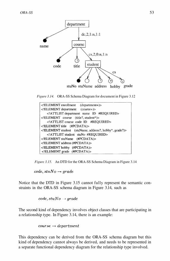
ORA-SS 53
Figure 3.14. ORA-SS Schema Diagram for document in Figure 3.12
Figure 3.15. An DTD for the ORA-SS Schema Diagram in Figure 3.14
Notice that the DTD in Figure 3.15 cannot fully represent the semantic con-straints in the ORA-SS schema diagram in Figure 3.14, such as
The second kind of dependency involves object classes that are participating ina relationship type. In Figure 3.14, there is an example:
This dependency can be derived from the ORA-SS schema diagram but thiskind of dependency cannot always be derived, and needs to be represented ina separate functional dependency diagram for the relationship type involved.

54
In general, functional dependencies of binary relationship types can be de-rived from the participation constraints in the ORA-SS schema diagram, but itmay not be possible for n-ary relationship types. Functional depen-dency diagrams can also be used with ORA-SS schema diagrams to capturethe same information. This information is useful when attempting to identifyredundancy in the repository. However, because functional dependencies ofbinary relationship types can be derived from the participation constraints ofthe binary relationship types in the ORA-SS schema diagrams, there is no needto draw functional dependency diagrams for binary relationships.
In functional dependency diagrams the object classes are represented by la-beled rectangles, the relationship types by diamonds labeled only with the re-lationship type name, and the edges carry the cardinality of the object classes.Each edge label has where is the number of functional depen-dencies among the object classes. The on each edge emanating from arelationship type relate to each other and represent one functional dependency,as do the etc. Each represents the object classes cardinality in thatfunctional dependency, and is denoted as 1, or –.
Consider a ternary relationship among three object classes, A, B and C. Ifthe are 1 respectively, then we can derive the functional dependency
In fact, an object class with cardinality 1 will appear on the righthand side of the functional dependency, except in the case where all objectclasses have cardinality 1. In this case, any of the object classes can appear onthe right hand side of the functional dependency. A hyphen (“-”) indicates thatthe object class does not take part in the dependency.
Example 3.14 The functional dependency diagram in Figure 3.16 enhancesthe information in Figure 3.7. Suppose that a tutor can teach many tutorialsin one course, each student in a course has one tutor, and a tutor can teachtutorials in only one course. The functional dependencies that model theseconstraints are:
The first functional dependency can be derived from Figure 3.7, but the sec-ond cannot. The functional dependencies among the object classes student,course, and tutor are shown on the edges in Figure 3.16. The edge fromstudent has the label the edge from course has the label and theedge from tutor has the label Consider the first character in each label,
and 1 respectively, they indicate that for each student and each course,there is at most one tutor, and from this we can derive the functional depen-
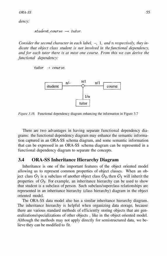
ORA-SS 55
dency:
Consider the second character in each label, –, 1, and respectively, they in-dicate that object class student is not involved in the functional dependency,and for each tutor there is at most one course. From this we can derive thefunctional dependency:
Figure 3.16. Functional dependency diagram enhancing the information in Figure 3.7
There are two advantages in having separate functional dependency dia-grams: the functional dependency diagram may enhance the semantic informa-tion captured in an ORA-SS schema diagram, and some semantic informationthat can be expressed in an ORA-SS schema diagram can be represented in afunctional dependency diagram to separate the concepts.
3.4 ORA-SS Inheritance Hierarchy DiagramInheritance is one of the important features of the object oriented model
allowing us to represent common properties of object classes. When an ob-ject class is a subclass of another object class then will inherit theproperties of For example, an inheritance hierarchy can be used to showthat student is a subclass of person. Such subclass/superclass relationships arerepresented in an inheritance hierarchy (class hierarchy) diagram in the objectoriented model.
The ORA-SS data model also has a similar inheritance hierarchy diagram.The inheritance hierarchy is helpful when organizing data storage, becausethere are various standard methods of efficiently storing objects that are gen-eralizations/specializations of other objects , like in the object oriented model.Although the methods may not apply directly for semistructured data, we be-lieve they can be modified to fit.

56
Figure 3.17. ORA-SS Schema Diagram and Inheritance Diagram
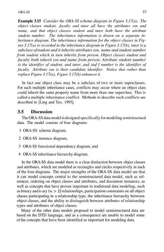
ORA-SS 57
Example 3.15 Consider the ORA-SS schema diagram in Figure 3.17(a). Theobject classes student, faculty and tutor all have the attributes ssn andname, and that object classes student and tutor both have the attributestudent number. The inheritance information is drawn on a separate in-heritance diagram. The inheritance information for the object classes in Fig-ure 3.17(a) is recorded in the inheritance diagram in Figure 3.17(b), tutor is asubclass of student and it inherits attributes ssn, name and student numberfrom student which in turn inherits from person. Object classes student andfaculty both inherit ssn and name from person. Attribute student numberis the identifier of student, and tutor, and staf f number is the identifier offaculty. Attribute ssn is their candidate identifier. Notice that rather thanreplace Figure 3.17(a), Figure 3.17(b) enhances it.
In fact one object class may be a subclass of two or more superclasses.For such multiple inheritance cases, conflicts may occur where an object classcould inherit the same property name from more than one superclass. This iscalled a multiple inheritance conflict. Methods to describe such conflicts aredescribed in [Ling and Teo, 1993].
3.5 DiscussionThe ORA-SS data model is designed specifically for modeling semistructued
data. The model consists of four diagrams:
ORA-SS schema diagram,
ORA-SS instance diagram,
ORA-SS functional dependency diagram, and
ORA-SS inheritance hierarchy diagram.
1
2
3
4
In the ORA-SS data model there is a clear distinction between object classesand attributes, which are modeled as rectangles and circles respectively in eachof the four diagrams. The major strengths of the ORA-SS data model are thatit can model concepts central to the semistructured data model, such as ref-erences, ordering on object classes and attributes, and document instances, aswell as concepts that have proven important in traditional data modeling, suchas binary and n-ary relationships, participation constraints on all objectclasses participating in a relationship type, the inheritance hierarchy betweenobject classes, and the ability to distinguish between attributes of relationshiptypes and attributes of object classes.
Many of the other data models proposed to model semistructured data arebased on the DTD language, and as a consequence are unable to model someof the concepts that have been identified as important for modeling data.

This page intentionally left blank
Chapter 4
SCHEMA EXTRACTION
Unlike data stored in traditional relational or object-oriented databases, semistruc-tured data does not have a fixed schema that is known in advance and that canbe stored separately from the data. In fact, the structure of semistructured datais irregular, unknown, and changes often [Suciu, 1998].
The lack of external schema information renders the storage, indexing, andquerying of semistructured data inefficient, or even impossible. This leads tothe development of methods such as DataGuide [Goldman and Widom, 1997]to extract the schema from semistructured data. The focus of these techniquesis to extract the hierarchy structure of semistructured data. In contrast, ORA-SS is able to capture important semantic information such as objects classes,relationship types, attributes, degree of relationship types, participation con-straints of the object classes in the relationship types. Further, ORA-SS is ableto distinguish between attributes of object classes and attributes of relation-ship types. The ability to extract these semantics from the underlying data willgreatly facilitate the various stages of database design and usage.
Consider the attributes stuName and grade located below the object classstudent in the ORA-SS schema in Figure 4.1. The attribute stuName is anattribute of the object class student while the attribute grade belongs to the re-lationship type cs which involves the object classes course and student. There-fore, instead of simply storing grade with the attributes of student, we shouldstore grade together with the identifiers of the object classes student and course.
Such semantic information also alerts us to the fact that any view containingonly course and grade information will not be meaningful because we shouldnot omit the student information when considering the attribute grade.
In the rest of the chapter, we will present a set of schema extraction rules anda method to extract semantically rich ORA-SS schemas from XML documents.

60
Figure 4.1. Example ORA-SS schema
We will illustrate the schema extraction algorithm with an example and finallycompare the proposed approach with existing schema extraction methods.
4.1 Basic Extraction RulesBefore we can extract the schema from an XML document, we must have
some knowledge of the structure and syntax of the document. We propose threerules that are based on the XML syntax to guide our schema extraction process.
Rule E1. The XML document root element is considered as an unique entryinto the XML schema. A non-root XML element is classified as
an object if it has at least one attribute.
a simple attribute if it has only text content without attributes or subele-ments.
a composite attribute if it comprises of multiple subelements whose valuesare text.
1
2
3
A simple or composite attribute is single-valued if the XML element is notrepeated under its parent XML element, otherwise, it is a multivalued at-tribute.
This rule can be used to differentiate objects and attributes when they areboth expressed by XML elements. Consider the following segment of XMLdocument:
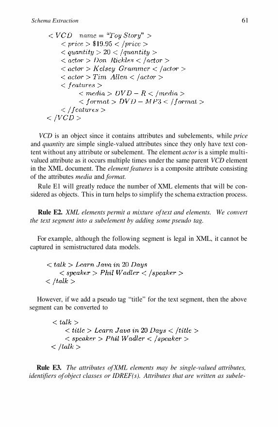
Schema Extraction 61
VCD is an object since it contains attributes and subelements, while priceand quantity are simple single-valued attributes since they only have text con-tent without any attribute or subelement. The element actor is a simple multi-valued attribute as it occurs multiple times under the same parent VCD elementin the XML document. The element features is a composite attribute consistingof the attributes media and format.
Rule E1 will greatly reduce the number of XML elements that will be con-sidered as objects. This in turn helps to simplify the schema extraction process.
Rule E2. XML elements permit a mixture of text and elements. We convertthe text segment into a subelement by adding some pseudo tag.
For example, although the following segment is legal in XML, it cannot becaptured in semistructured data models.
However, if we add a pseudo tag “title” for the text segment, then the abovesegment can be converted to
Rule E3. The attributes of XML elements may be single-valued attributes,identifiers of object classes or IDREF(s). Attributes that are written as subele-
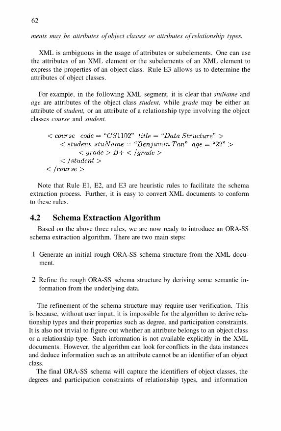
62
ments may be attributes of object classes or attributes of relationship types.
XML is ambiguous in the usage of attributes or subelements. One can usethe attributes of an XML element or the subelements of an XML element toexpress the properties of an object class. Rule E3 allows us to determine theattributes of object classes.
For example, in the following XML segment, it is clear that stuName andage are attributes of the object class student, while grade may be either anattribute of student, or an attribute of a relationship type involving the objectclasses course and student.
Note that Rule E1, E2, and E3 are heuristic rules to facilitate the schemaextraction process. Further, it is easy to convert XML documents to conformto these rules.
4.2 Schema Extraction AlgorithmBased on the above three rules, we are now ready to introduce an ORA-SS
schema extraction algorithm. There are two main steps:
Generate an initial rough ORA-SS schema structure from the XML docu-ment.
Refine the rough ORA-SS schema structure by deriving some semantic in-formation from the underlying data.
1
2
The refinement of the schema structure may require user verification. Thisis because, without user input, it is impossible for the algorithm to derive rela-tionship types and their properties such as degree, and participation constraints.It is also not trivial to figure out whether an attribute belongs to an object classor a relationship type. Such information is not available explicitly in the XMLdocuments. However, the algorithm can look for conflicts in the data instancesand deduce information such as an attribute cannot be an identifier of an objectclass.
The final ORA-SS schema will capture the identifiers of object classes, thedegrees and participation constraints of relationship types, and information
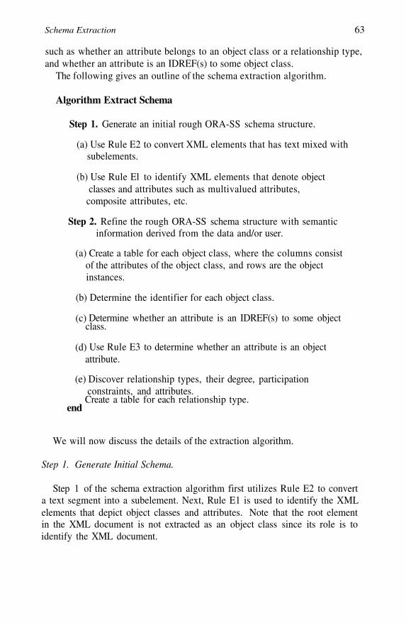
Schema Extraction 63
such as whether an attribute belongs to an object class or a relationship type,and whether an attribute is an IDREF(s) to some object class.
The following gives an outline of the schema extraction algorithm.
Algorithm Extract Schema
Step 1. Generate an initial rough ORA-SS schema structure.
Use Rule E2 to convert XML elements that has text mixed withsubelements.
(a)
(b) Use Rule El to identify XML elements that denote objectclasses and attributes such as multivalued attributes,
composite attributes, etc.
Step 2. Refine the rough ORA-SS schema structure with semanticinformation derived from the data and/or user.
(a) Create a table for each object class, where the columns consistof the attributes of the object class, and rows are the objectinstances.
Determine the identifier for each object class.
Determine whether an attribute is an IDREF(s) to some objectclass.
(b)
(c)
Use Rule E3 to determine whether an attribute is an objectattribute.
(d)
Discover relationship types, their degree, participation(e)constraints, and attributes.
Create a table for each relationship type.end
We will now discuss the details of the extraction algorithm.
Step 1. Generate Initial Schema.
Step 1 of the schema extraction algorithm first utilizes Rule E2 to converta text segment into a subelement. Next, Rule E1 is used to identify the XMLelements that depict object classes and attributes. Note that the root elementin the XML document is not extracted as an object class since its role is toidentify the XML document.

64
Step 2. Refine Schema.
(a) Create tables for object classes.
The algorithm creates a table for each object class, where the table name andthe object class name are the same as the XML element tag name. The columnsof the table consist of the attributes of the object class, and rows are the objectinstances. For a start, all the attributes of the XML element are considered asthe object class’s attributes. However, we add a mark “?” for attributes whichoriginate from XML subelements, since these may possibly be relationshipattributes.
Single-valued composite attributes are represented by their component at-tributes. A simple multivalued attribute such as X, which has been identifiedby Rule El, is denoted as X * ( ? ) . The value of this column for a tuple is theset of subelement X values under the parent element (i.e., an element whichrepresents an identifier of the object class).
Similarly, multiple composite attributes are represented as a nested table inthe object class relation with all the component attributes as the attributes ofthe nested table.
(b) Determine identifier of object classes.
In order to determine the identifier of each object class, the algorithm willanalyze the single-valued attribute values of each object class.
A single-valued attribute is a possible object class identifier if each of itsattribute values determines a unique value for the other attributes which havenot been marked with a “?” in the object class table.
The user will be asked to verify the identifier of the object class. We observethat the identifier is typically the first attribute in the XML element attributelist. Note that attributes that contain null values cannot be an identifier.
(c) Determine IDREF(S).
The algorithm will also determine whether an attribute is a potential IDREF(S)to some object class. An IDREF consists of only one value, while an IDREFScomprises of values that are separated by blanks. Since the identifier of an ob-ject class cannot be also an IDREF to other object class, the algorithm will an-alyze the non-identifier single-valued attribute of each object class, and checkwhether all its values appear as identifier values of some object class.
Further, if the algorithm finds blank characters in an attribute value, then itwill tokenize the value to become a set of values, using the blank as the sep-arator. If all the tokenized values correspond to the values of identifier value
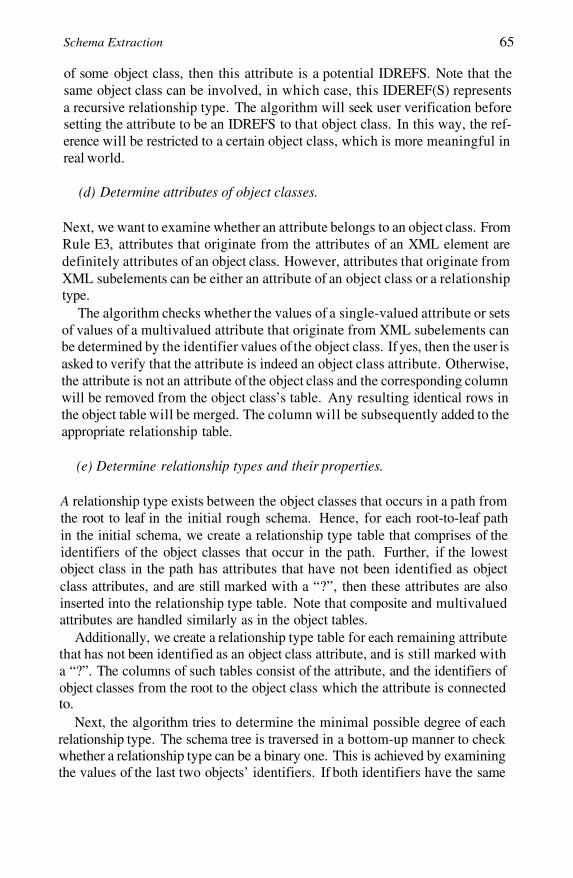
Schema Extraction 65
of some object class, then this attribute is a potential IDREFS. Note that thesame object class can be involved, in which case, this IDEREF(S) representsa recursive relationship type. The algorithm will seek user verification beforesetting the attribute to be an IDREFS to that object class. In this way, the ref-erence will be restricted to a certain object class, which is more meaningful inreal world.
(d) Determine attributes of object classes.
Next, we want to examine whether an attribute belongs to an object class. FromRule E3, attributes that originate from the attributes of an XML element aredefinitely attributes of an object class. However, attributes that originate fromXML subelements can be either an attribute of an object class or a relationshiptype.
The algorithm checks whether the values of a single-valued attribute or setsof values of a multivalued attribute that originate from XML subelements canbe determined by the identifier values of the object class. If yes, then the user isasked to verify that the attribute is indeed an object class attribute. Otherwise,the attribute is not an attribute of the object class and the corresponding columnwill be removed from the object class’s table. Any resulting identical rows inthe object table will be merged. The column will be subsequently added to theappropriate relationship table.
(e) Determine relationship types and their properties.
A relationship type exists between the object classes that occurs in a path fromthe root to leaf in the initial rough schema. Hence, for each root-to-leaf pathin the initial schema, we create a relationship type table that comprises of theidentifiers of the object classes that occur in the path. Further, if the lowestobject class in the path has attributes that have not been identified as objectclass attributes, and are still marked with a “?”, then these attributes are alsoinserted into the relationship type table. Note that composite and multivaluedattributes are handled similarly as in the object tables.
Additionally, we create a relationship type table for each remaining attributethat has not been identified as an object class attribute, and is still marked witha “?”. The columns of such tables consist of the attribute, and the identifiers ofobject classes from the root to the object class which the attribute is connectedto.
Next, the algorithm tries to determine the minimal possible degree of eachrelationship type. The schema tree is traversed in a bottom-up manner to checkwhether a relationship type can be a binary one. This is achieved by examiningthe values of the last two objects’ identifiers. If both identifiers have the same
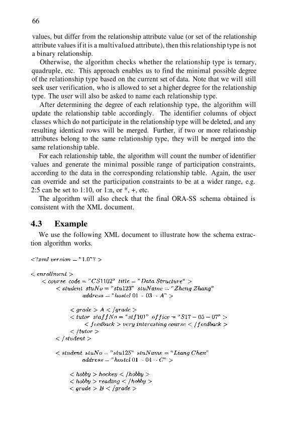
66
values, but differ from the relationship attribute value (or set of the relationshipattribute values if it is a multivalued attribute), then this relationship type is nota binary relationship.
Otherwise, the algorithm checks whether the relationship type is ternary,quadruple, etc. This approach enables us to find the minimal possible degreeof the relationship type based on the current set of data. Note that we will stillseek user verification, who is allowed to set a higher degree for the relationshiptype. The user will also be asked to name each relationship type.
After determining the degree of each relationship type, the algorithm willupdate the relationship table accordingly. The identifier columns of objectclasses which do not participate in the relationship type will be deleted, and anyresulting identical rows will be merged. Further, if two or more relationshipattributes belong to the same relationship type, they will be merged into thesame relationship table.
For each relationship table, the algorithm will count the number of identifiervalues and generate the minimal possible range of participation constraints,according to the data in the corresponding relationship table. Again, the usercan override and set the participation constraints to be at a wider range, e.g.2:5 can be set to 1:10, or 1:n, or *, +, etc.
The algorithm will also check that the final ORA-SS schema obtained isconsistent with the XML document.
4.3 ExampleWe use the following XML document to illustrate how the schema extrac-
tion algorithm works.
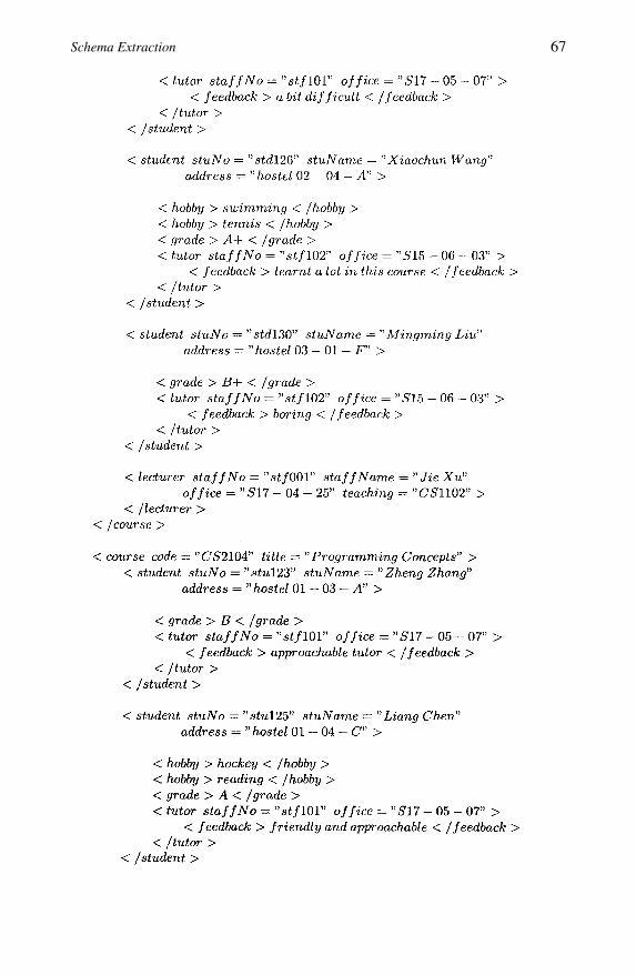
Schema Extraction 67
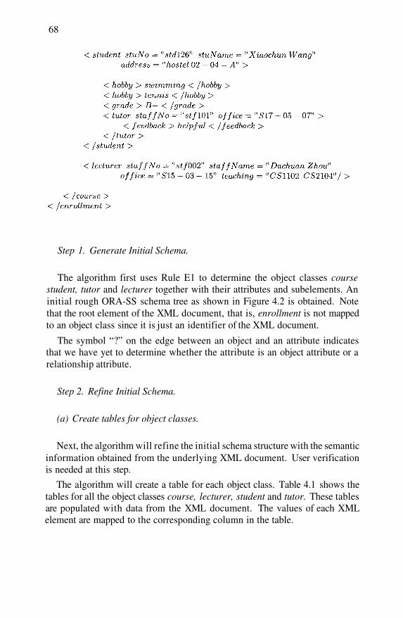
68
Step 1. Generate Initial Schema.
The algorithm first uses Rule E1 to determine the object classes coursestudent, tutor and lecturer together with their attributes and subelements. Aninitial rough ORA-SS schema tree as shown in Figure 4.2 is obtained. Notethat the root element of the XML document, that is, enrollment is not mappedto an object class since it is just an identifier of the XML document.
The symbol “?” on the edge between an object and an attribute indicatesthat we have yet to determine whether the attribute is an object attribute or arelationship attribute.
Step 2. Refine Initial Schema.
(a) Create tables for object classes.
Next, the algorithm will refine the initial schema structure with the semanticinformation obtained from the underlying XML document. User verificationis needed at this step.
The algorithm will create a table for each object class. Table 4.1 shows thetables for all the object classes course, lecturer, student and tutor. These tablesare populated with data from the XML document. The values of each XMLelement are mapped to the corresponding column in the table.

Schema Extraction 69
Figure 4.2. Initial ORA-SS schema structure after Step 1
(b) Determine identifiers of object classes.
Next, the algorithm will analyze the instances in the object class tables todetermine the identifier for the object classes. We can use any data miningtechnique to mine possible functional dependencies among the attributes in theobject tables. Attributes that are marked with “?” are excluded here.
From the instances in the object class course table (Table 4.1), we have thefunctional dependencies
This implies that both code and title are candidate keys of course. Sincecode is the first attribute, the algorithm will first ask the user if code is theidentifier of the object class course. If it is not, then the algorithm will proceedto ask the user whether title is the identifier of course.
For the object class lecturer, we have the functional dependency
Thus, the algorithm will ask the user to verify that staffNo is the identifierof the object class lecturer.
From the instances in the object class student, we have the functional de-pendency
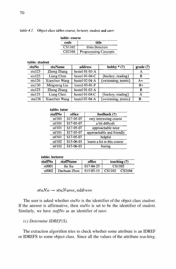
70
The user is asked whether stuNo is the identifier of the object class student.If the answer is affirmative, then stuNo is set to be the identifier of student.Similarly, we have staffNo as an identifier of tutor.
(c) Determine IDREF(S).
The extraction algorithm tries to check whether some attribute is an IDREFor IDREFS to some object class. Since all the values of the attribute teaching,

Schema Extraction 71
that is, CS1102 and CS2104 after tokenization, form a subset of the values ofthe object identifier / candidate key code of the object class course, it is highlylikely that teaching is an IDREF to the object class course. This observation ishighlighted to the user who confirms that teaching is an IDREF to the objectclass course.
(d) Determine attributes of object classes.
This step examines whether the attributes that are marked with “?” are at-tributes of object classes. Since each student in Table 4.1 has a unique set ofhobby values, the user is asked whether hobby is a multivalued attribute ofstudent. If it is, then we mark the attribute hobby with an “*”.
The functional dependency
does not hold because student stu123 has two grade values A and B. Therefore,grade is not an attribute of the student object class.
Similarly, the attribute feedback is also not an object class attribute.
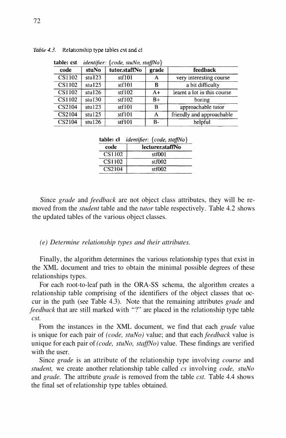
72
Since grade and feedback are not object class attributes, they will be re-moved from the student table and the tutor table respectively. Table 4.2 showsthe updated tables of the various object classes.
(e) Determine relationship types and their attributes.
Finally, the algorithm determines the various relationship types that exist inthe XML document and tries to obtain the minimal possible degrees of theserelationships types.
For each root-to-leaf path in the ORA-SS schema, the algorithm creates arelationship table comprising of the identifiers of the object classes that oc-cur in the path (see Table 4.3). Note that the remaining attributes grade andfeedback that are still marked with “?” are placed in the relationship type tablecst.
From the instances in the XML document, we find that each grade valueis unique for each pair of (code, stuNo) value; and that each feedback value isunique for each pair of (code, stuNo, staffNo) value. These findings are verifiedwith the user.
Since grade is an attribute of the relationship type involving course andstudent, we create another relationship table called cs involving code, stuNoand grade. The attribute grade is removed from the table cst. Table 4.4 showsthe final set of relationship type tables obtained.

Schema Extraction 73
Based on the data in Table 4.4, the minimal possible parent participationconstraint and child participation constraint of the relationship type cs couldbe 3:4 and 1:2 respectively, that is, 3-4 students can be enrolled in a course,and a student can take 1-2 courses.
Similarly, the minimal possible parent (student) participation constraint andchild (tutor) participation constraint of relationship type cst could be 1:1 and2:2 respectively, For the relationship type cs, the user is allowed to change thethe parent participation constraint to 3:n, where indicates that the maximumoccurrences is infinitely many.
The user can also change the child participation constraint to 1:6, that is,a student can take a maximum of 6 courses. The new constraints are superranges of that discovered by the system.
Figure 4.3 shows the final ORA-SS schema tree extracted from our exampleXML document. Note that the system should verify that the final ORA-SSschema tree is consistent with the original XML document.

74
Figure 4.4. DataGuide extracted from sample XML document
Researchers have proposed various methods to extract semistructured dataschema. These include DataGuide [Goldman and Widom, 1997], and approxi-mate graph schema [Wang et al., 2000]. Figure 4.4 shows the DataGuide that isextracted from our example XML document. We observe that the DataGuide issimilar to the initial ORA-SS schema tree obtained in Step 1 of the extractionalgorithm.
It is clear that DataGuide and a set of data path expressions only discoverthe hierarchy of the semistructured data. There is no knowledge of objectclasses and their identifiers, relationship types, attributes of object classes andrelationship types, participation constraints, etc. These models are not ableto distinguish between the different semantics of attributes such as hobby andgrade. Both of these attributes are considered as subelements of the object
Figure 4.3. Final ORA-SS schema obtained after Step 2
4.4 Discussion

Schema Extraction 75
class student although grade is a relationship attribute. Thus, the usage ofthese schemas is quite limited.
Compared to existing approaches which extract the structural informationof XML documents, our extraction algorithm carries out additional checkingand analysis of the XML document to derive semantic information.
Database designers will be aware that stuNo is the identifier of object classstudent; attribute grade belongs to a binary relationship type between courseand student; teaching is an IDREFS attribute referencing to object class course;etc Such semantic information will lead to higher quality schemas, and fa-cilitate all levels of database design, implementation and usage. For exam-ple, [Chen et al., 2002] gives an algorithm for designing valid XML viewsusing ORA-SS data model; and [Mo and Ling, 2002] gives an algorithm tomap ORA-SS schema to object-relational database, which can be used to storeXML data efficiently. The set of tables obtained for the object-relational databaseis exactly the same as the final object class tables and relationship type tables(Tables 4.2 and 4.4). Details will be discussed in Chapter 7.
4.5 SummaryIn this chapter, we have discussed the importance of a schema for semistruc-
tured data. We have described an algorithm to extract ORA-SS schema fromXML documents. First, the algorithm generates an initial ORA-SS schemawhich contains structural information, and differentiates objects from attributes,and single-valued attributes from multivalued attributes. Next, the algorithmtries to infer semantic information such as whether an attribute which appearsas a subelement in the XML document belongs to an object class or a rela-tionship type, the keys of object classes, the IDREF(S) attributes, and degreesand participation constraints of relationship types, etc. User inputs are neededin this step to verify the various semantics discovered. We have demonstratedthat the ability to extract a semantically rich schema from XML documents isuseful and important in database design, implementation and usage.
For future work, it would be useful to extend the extraction algorithm tosupport additional features in the ORA-SS schema. For example, the ORA-SSschema has a concept of “ANY” attribute, which is used to capture infrequentlyused attributes. ORA-SS also supports ordering on instances of an object class,values of an attribute and set of attributes, and the inheritance relationship. Fur-ther, if an XML document is updated, the extract ORA-SS schema should alsobe modified to reflect the changes in the underlying data. It will be importantto develop an efficient incremental method to maintain the extracted schema.

This page intentionally left blank
Chapter 5
NORMALIZATION
Reducing data redundancy is an important step in relational database design.Designers reduce data redundancy by normalizing the database schema to oneof the normal forms (e.g. 2NF, 3NF, BCNF, 4NF etc.) using constraints on theattributes in the schema. Normalization of relational databases is recognizedin the research community where it has been widely researched, and also inindustry where it is regarded as a useful technique. In contrast, there has beenlimited research on normalization of semistructured data [Arenas and Libkin,2004; Embley and Mok, 2001; Lee et al., 1999; Mani et al., 2001; Wu et al.,2001a].
The interest in storing semistructured data in repositories has increased withthe increased use and complexity of semistructured data. Semistructured datacan be stored in a native XML database, an XML enabled database, or a moretraditional database such as a nested relational or relational database. Currentresearch that maps semistructured data to a traditional database [Deutsch et al.,1999; Florescu and Kossmann, 1999; Shanmugasundaram et al., 1999] ignoresthe detection of redundancy, although, some of the same kinds of anomaliesthat arise in relational databases can arise in repositories that store semistruc-tured data. For example, update, insertion and deletion anomalies exist inrepositories that store semistructured data when information is duplicated.
In this chapter, we define a normal form for ORA-SS schema diagrams(called NF ORA-SS schema diagram) which is based on a normal form fornested relations, and describe an algorithm that maps an ORA-SS schema di-agram into an NF ORA-SS schema diagram. Section 5.1 gives a example tohighlight the need for normalization in semistructured data model. Section 5.2reviews definitions from [Ling and Yan, 1994]. In Section 5.3 we define anormal form for ORA-SS schema diagrams and in Section 5.4 we describe an

78
Figure 5.1. Example XML document with redundant information
algorithm that maps an ORA-SS schema diagram to an NF ORA-SS schemadiagram.
5.1 Motivating ExampleThe following example demonstrates how redundancy can occur in semistruc-
tured data and highlights the need for normalization.
Example 5.1 Consider the XML document in Figure 5.1 that contains infor-mation about courses in a department and the students who take the courses.In this document, there are two courses (with code CS1102 and CS2104) andtwo students (with stuNo stu123 and stu125). The details of the students, suchas stuName, address and hobby, are repeated for each course the student takes.
This duplication of information causes a number of problems. For example,if a student changes their address, it must be updated everywhere the addressis stored, that is it must be updated in every course the student takes. If a newcourse is inserted and student stu125 enrolls in that course then the details of
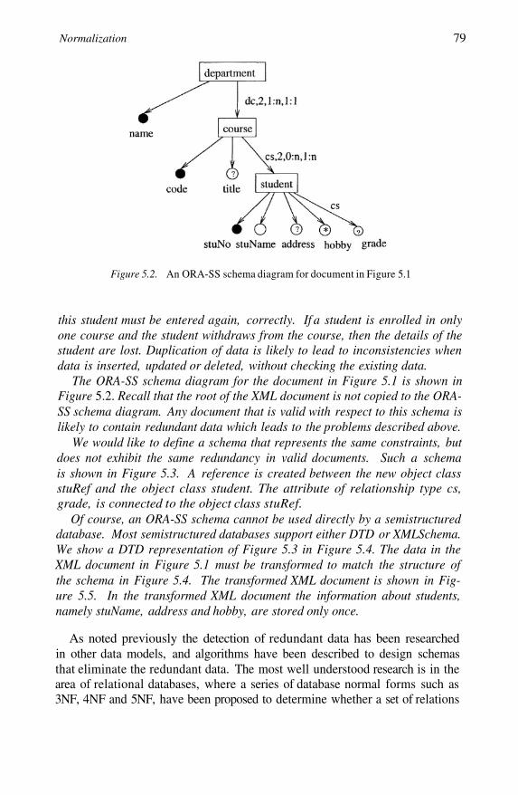
Normalization 79
Figure 5.2. An ORA-SS schema diagram for document in Figure 5.1
this student must be entered again, correctly. If a student is enrolled in onlyone course and the student withdraws from the course, then the details of thestudent are lost. Duplication of data is likely to lead to inconsistencies whendata is inserted, updated or deleted, without checking the existing data.
The ORA-SS schema diagram for the document in Figure 5.1 is shown inFigure 5.2. Recall that the root of the XML document is not copied to the ORA-SS schema diagram. Any document that is valid with respect to this schema islikely to contain redundant data which leads to the problems described above.
We would like to define a schema that represents the same constraints, butdoes not exhibit the same redundancy in valid documents. Such a schemais shown in Figure 5.3. A reference is created between the new object classstuRef and the object class student. The attribute of relationship type cs,grade, is connected to the object class stuRef.
Of course, an ORA-SS schema cannot be used directly by a semistructureddatabase. Most semistructured databases support either DTD or XMLSchema.We show a DTD representation of Figure 5.3 in Figure 5.4. The data in theXML document in Figure 5.1 must be transformed to match the structure ofthe schema in Figure 5.4. The transformed XML document is shown in Fig-ure 5.5. In the transformed XML document the information about students,namely stuName, address and hobby, are stored only once.
As noted previously the detection of redundant data has been researchedin other data models, and algorithms have been described to design schemasthat eliminate the redundant data. The most well understood research is in thearea of relational databases, where a series of database normal forms such as3NF, 4NF and 5NF, have been proposed to determine whether a set of relations
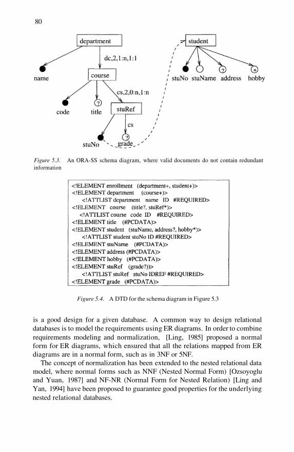
80
Figure 5.3. An ORA-SS schema diagram, where valid documents do not contain redundantinformation
Figure 5.4. A DTD for the schema diagram in Figure 5.3
is a good design for a given database. A common way to design relationaldatabases is to model the requirements using ER diagrams. In order to combinerequirements modeling and normalization, [Ling, 1985] proposed a normalform for ER diagrams, which ensured that all the relations mapped from ERdiagrams are in a normal form, such as in 3NF or 5NF.
The concept of normalization has been extended to the nested relational datamodel, where normal forms such as NNF (Nested Normal Form) [Ozsoyogluand Yuan, 1987] and NF-NR (Normal Form for Nested Relation) [Ling andYan, 1994] have been proposed to guarantee good properties for the underlyingnested relational databases.
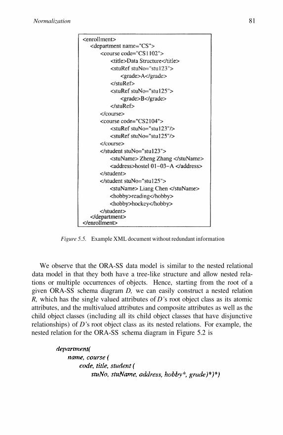
Normalization 81
Figure 5.5. Example XML document without redundant information
We observe that the ORA-SS data model is similar to the nested relationaldata model in that they both have a tree-like structure and allow nested rela-tions or multiple occurrences of objects. Hence, starting from the root of agiven ORA-SS schema diagram D, we can easily construct a nested relationR, which has the single valued attributes of D’s root object class as its atomicattributes, and the multivalued attributes and composite attributes as well as thechild object classes (including all its child object classes that have disjunctiverelationships) of D’s root object class as its nested relations. For example, thenested relation for the ORA-SS schema diagram in Figure 5.2 is
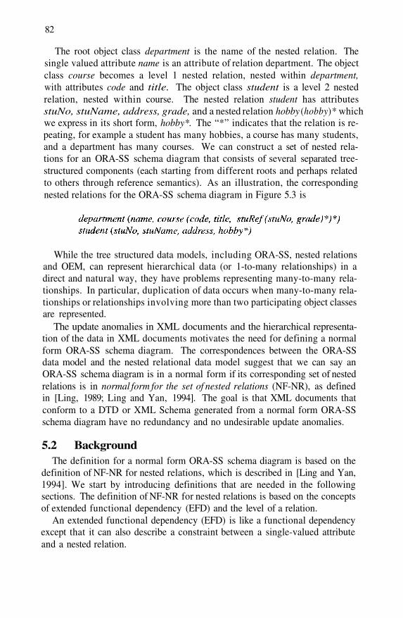
82
The root object class department is the name of the nested relation. Thesingle valued attribute name is an attribute of relation department. The objectclass course becomes a level 1 nested relation, nested within department,with attributes code and title. The object class student is a level 2 nestedrelation, nested within course. The nested relation student has attributesstuNo, stuName, address, grade, and a nested relation hobby (hobby)* whichwe express in its short form, hobby*. The “*” indicates that the relation is re-peating, for example a student has many hobbies, a course has many students,and a department has many courses. We can construct a set of nested rela-tions for an ORA-SS schema diagram that consists of several separated tree-structured components (each starting from different roots and perhaps relatedto others through reference semantics). As an illustration, the correspondingnested relations for the ORA-SS schema diagram in Figure 5.3 is
While the tree structured data models, including ORA-SS, nested relationsand OEM, can represent hierarchical data (or 1-to-many relationships) in adirect and natural way, they have problems representing many-to-many rela-tionships. In particular, duplication of data occurs when many-to-many rela-tionships or relationships involving more than two participating object classesare represented.
The update anomalies in XML documents and the hierarchical representa-tion of the data in XML documents motivates the need for defining a normalform ORA-SS schema diagram. The correspondences between the ORA-SSdata model and the nested relational data model suggest that we can say anORA-SS schema diagram is in a normal form if its corresponding set of nestedrelations is in normal form for the set of nested relations (NF-NR), as definedin [Ling, 1989; Ling and Yan, 1994]. The goal is that XML documents thatconform to a DTD or XML Schema generated from a normal form ORA-SSschema diagram have no redundancy and no undesirable update anomalies.
5.2 BackgroundThe definition for a normal form ORA-SS schema diagram is based on the
definition of NF-NR for nested relations, which is described in [Ling and Yan,1994]. We start by introducing definitions that are needed in the followingsections. The definition of NF-NR for nested relations is based on the conceptsof extended functional dependency (EFD) and the level of a relation.
An extended functional dependency (EFD) is like a functional dependencyexcept that it can also describe a constraint between a single-valued attributeand a nested relation.
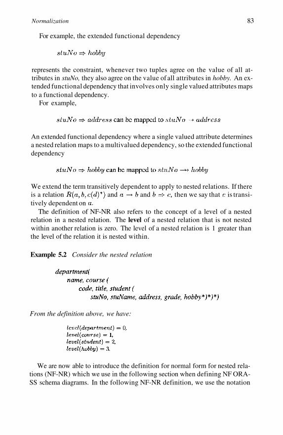
Normalization 83
For example, the extended functional dependency
represents the constraint, whenever two tuples agree on the value of all at-tributes in stuNo, they also agree on the value of all attributes in hobby. An ex-tended functional dependency that involves only single valued attributes mapsto a functional dependency.
For example,
An extended functional dependency where a single valued attribute determinesa nested relation maps to a multivalued dependency, so the extended functionaldependency
We extend the term transitively dependent to apply to nested relations. If thereis a relation and and then we say that is transi-tively dependent on
The definition of NF-NR also refers to the concept of a level of a nestedrelation in a nested relation. The level of a nested relation that is not nestedwithin another relation is zero. The level of a nested relation is 1 greater thanthe level of the relation it is nested within.
Example 5.2 Consider the nested relation
From the definition above, we have:
We are now able to introduce the definition for normal form for nested rela-tions (NF-NR) which we use in the following section when defining NF ORA-SS schema diagrams. In the following NF-NR definition, we use the notation
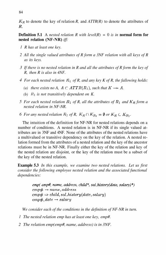
84
to denote the key of relation R, and ATTR(R) to denote the attributes ofR.
Definition 5.1 A nested relation R with level(R) = 0 is in normal form fornested relation (NF-NR) iff:
R has at least one key.
All the single valued attributes of R form a 3NF relation with all keys of Ras its keys.
If there is no nested relation in R and all the attributes of R form the key ofR, then R is also in 4NF.
For each nested relation of R, and any key K of R, the fallowing holds:
1
2
3
4
there exists no A, such that
is not transitively dependent on K.
(a)
(b)
For each nested relation of R, all the attributes of and form anested relation in NF-NR.
For any nested relation of R, or
5
6
The intuition of the definition for NF-NR for nested relations depends on anumber of conditions. A nested relation is in NF-NR if its single valued at-tributes are in 3NF and 4NF. None of the attributes of the nested relations havea multivalued or transitive dependency on the key of the relation. A nested re-lation formed from the attributes of a nested relation and the key of the ancestorrelations must be in NF-NR. Finally either the key of the relation and key ofthe nested relation are disjoint, or the key of the relation must be a subset ofthe key of the nested relation.
Example 5.3 In this example, we examine two nested relations. Let us firstconsider the following employee nested relation and the associated functionaldependencies:
We consider each of the conditions in the definition of NF-NR in turn.
The nested relation emp has at least one key, emp#.
The relation emp(emp#, name, address) is in 3NF.
1
2
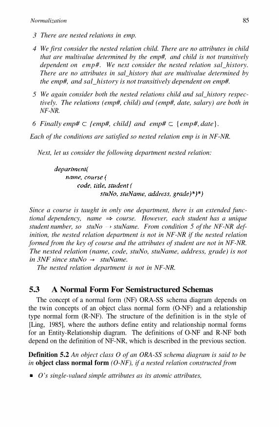
Normalization 85
3
4
There are nested relations in emp.
We first consider the nested relation child. There are no attributes in childthat are multivalue determined by the emp#, and child is not transitivelydependent on emp#. We next consider the nested relation sal_history.There are no attributes in sal_history that are multivalue determined bythe emp#, and sal_history is not transitively dependent on emp#.
5
6
We again consider both the nested relations child and sal_history respec-tively. The relations (emp#, child) and (emp#, date, salary) are both inNF-NR.
Finally emp# {emp#, child} and emp# {emp#, date}.
Each of the conditions are satisfied so nested relation emp is in NF-NR.
Next, let us consider the following department nested relation:
Since a course is taught in only one department, there is an extended func-tional dependency, name course. However, each student has a uniquestudent number, so stuNo stuName. From condition 5 of the NF-NR def-inition, the nested relation department is not in NF-NR if the nested relationformed from the key of course and the attributes of student are not in NF-NR.The nested relation (name, code, stuNo, stuName, address, grade) is notin 3NF since stuNo stuName.
The nested relation department is not in NF-NR.
5.3 A Normal Form For Semistructured SchemasThe concept of a normal form (NF) ORA-SS schema diagram depends on
the twin concepts of an object class normal form (O-NF) and a relationshiptype normal form (R-NF). The structure of the definition is in the style of[Ling, 1985], where the authors define entity and relationship normal formsfor an Entity-Relationship diagram. The definitions of O-NF and R-NF bothdepend on the definition of NF-NR, which is described in the previous section.
Definition 5.2 An object class O of an ORA-SS schema diagram is said to bein object class normal form (O-NF), if a nested relation constructed from
O’s single-valued simple attributes as its atomic attributes,
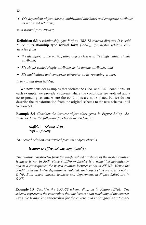
86
O’s dependent object classes, multivalued attributes and composite attributesas its nested relations,
is in normal form NF-NR.
Definition 5.3 A relationship type R of an ORA-SS schema diagram D is saidto be in relationship type normal form (R-NF), if a nested relation con-structed from
the identifiers of the participating object classes as its single values atomicattributes,
R’s single valued simple attributes as its atomic attributes, and
R’s multivalued and composite attributes as its repeating groups,
is in normal form NF-NR.
We now consider examples that violate the O-NF and R-NF conditions. Ineach example, we provide a schema where the conditions are violated and acorresponding schema where the conditions are not violated but we do notdescribe the transformation from the original schema to the new schema untilSection 5.4.
Example 5.4 Consider the lecturer object class given in Figure 5.6(a). As-sume we have the following functional dependencies:
The nested relation constructed from this object class is
The relation constructed from the single valued attributes of the nested relationlecturer is not in 3NF, since staffNo faculty is a transitive dependency,and as a consequence the nested relation lecturer is not in NF-NR. Hence thecondition in the O-NF definition is violated, and object class lecturer is not inO-NF. Both object classes, lecturer and department, in Figure 5.6(b) are inO-NF.
Example 5.5 Consider the ORA-SS schema diagram in Figure 5.7(a). Theschema represents the constraints that the lecturer can teach any of the coursesusing the textbooks as prescribed for the course, and is designed as a ternary
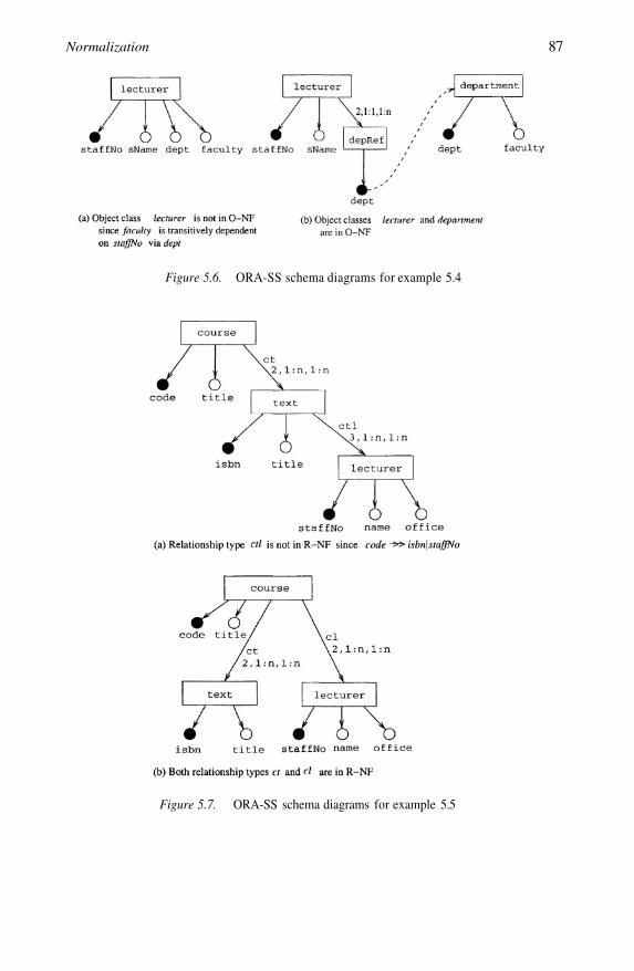
Normalization 87
Figure 5.6. ORA-SS schema diagrams for example 5.4
Figure 5.7. ORA-SS schema diagrams for example 5.5

88
relationship among course, text and lecturer. The textbooks of a course shouldbe independent of the lecturer that teaches the course, i.e., the following mul-tivalued dependency (MVD) exists:
Consider the nested relation ctl (code, isbn, staffNo) built from the identifiers ofthe participating object classes and attributes of the relationship type ctl. Thisnested relation is not in NF-NR since the corresponding relation is not in 4NFbecause of the above MVD. The condition in the R-NF definition is violated,and therefore the relationship type ctl is not in R-NF. A schema diagram inwhich both relationship types, ct and cl, are in R-NF is shown in Figure 5.7(b).The object class lecturer is promoted to be a direct child of the object classcourse.
We are now in a position to define a normal form for ORA-SS schema dia-grams.
Definition 5.4 An ORA-SS schema diagram D is in normal form (NF) if andonly if it satisfies the following five conditions:
1
2
3
Every object class O in D is in O-NF.
Every relationship type R in D is in R-NF.
The following two cases are satisfied:
(a) If R is a binary relationship type with parent object class A and childobject class B, and either B is a dependent object class that has an IDDrelationship type with A, or R is a one-to-many or one-to-one relation-ship type from A to B then all B’s attributes are connected to B, and allthe attributes of R are connected to B.
(b) If R is an n-ary relationship type with n (n>2) participating objectclasses and the path going from the top of D linkingthose object classes is then for each object class
(i)
(ii)
has an i-ary relationship type with ancestor object classes
If is a dependent object class that has an IDD relationship typewith its ancestors, or the functional dependency between andits ancestors, can be derived from thedependency constraints specified for the schema then the attributesof are connected to object class and the attributes of areconnected to
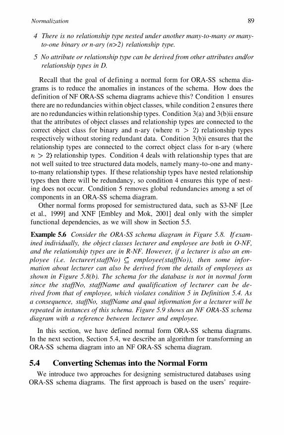
Normalization 89
4
5
There is no relationship type nested under another many-to-many or many-to-one binary or n-ary (n>2) relationship type.
No attribute or relationship type can be derived from other attributes and/orrelationship types in D.
Recall that the goal of defining a normal form for ORA-SS schema dia-grams is to reduce the anomalies in instances of the schema. How does thedefinition of NF ORA-SS schema diagrams achieve this? Condition 1 ensuresthere are no redundancies within object classes, while condition 2 ensures thereare no redundancies within relationship types. Condition 3(a) and 3(b)ii ensurethat the attributes of object classes and relationship types are connected to thecorrect object class for binary and n-ary (where relationship typesrespectively without storing redundant data. Condition 3(b)i ensures that therelationship types are connected to the correct object class for n-ary (where
relationship types. Condition 4 deals with relationship types that arenot well suited to tree structured data models, namely many-to-one and many-to-many relationship types. If these relationship types have nested relationshiptypes then there will be redundancy, so condition 4 ensures this type of nest-ing does not occur. Condition 5 removes global redundancies among a set ofcomponents in an ORA-SS schema diagram.
Other normal forms proposed for semistructured data, such as S3-NF [Leeet al., 1999] and XNF [Embley and Mok, 2001] deal only with the simplerfunctional dependencies, as we will show in Section 5.5.
Example 5.6 Consider the ORA-SS schema diagram in Figure 5.8. If exam-ined individually, the object classes lecturer and employee are both in O-NF,and the relationship types are in R-NF. However, if a lecturer is also an em-ployee (i.e. lecturer(staffNo) employee(staffNo)), then some infor-mation about lecturer can also be derived from the details of employees asshown in Figure 5.8(b). The schema for the database is not in normal formsince the staffNo, staffName and qualification of lecturer can be de-rived from that of employee, which violates condition 5 in Definition 5.4. Asa consequence, staffNo, staffName and qual information for a lecturer will berepeated in instances of this schema. Figure 5.9 shows an NF ORA-SS schemadiagram with a reference between lecturer and employee.
In this section, we have defined normal form ORA-SS schema diagrams.In the next section, Section 5.4, we describe an algorithm for transforming anORA-SS schema diagram into an NF ORA-SS schema diagram.
5.4 Converting Schemas into the Normal FormWe introduce two approaches for designing semistructured databases using
ORA-SS schema diagrams. The first approach is based on the users’ require-
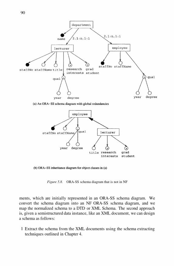
90
Figure 5.8. ORA-SS schema diagram that is not in NF
ments, which are initially represented in an ORA-SS schema diagram. Weconvert the schema diagram into an NF ORA-SS schema diagram, and wemap the normalized schema to a DTD or XML Schema. The second approachis, given a semistructured data instance, like an XML document, we can designa schema as follows:
1 Extract the schema from the XML documents using the schema extractingtechniques outlined in Chapter 4.
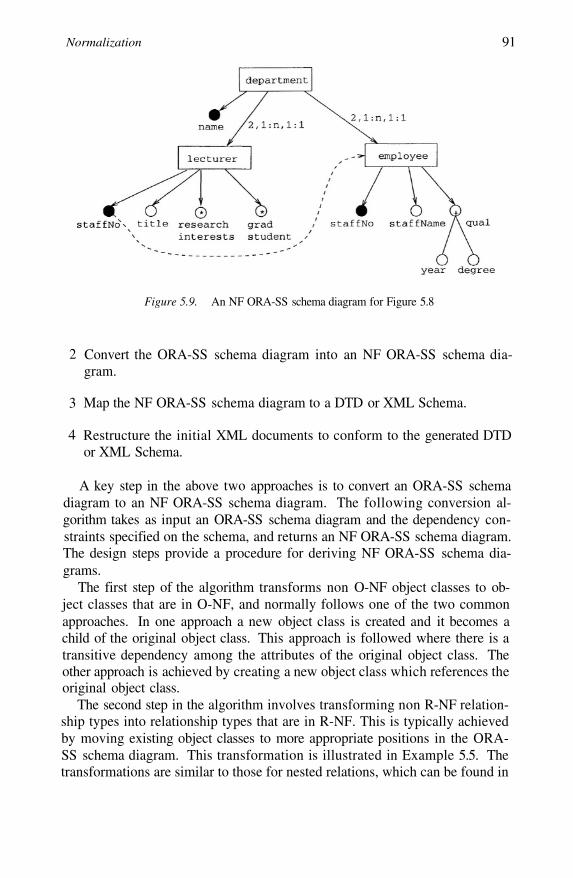
Normalization 91
Figure 5.9. An NF ORA-SS schema diagram for Figure 5.8
2
3
4
Convert the ORA-SS schema diagram into an NF ORA-SS schema dia-gram.
Map the NF ORA-SS schema diagram to a DTD or XML Schema.
Restructure the initial XML documents to conform to the generated DTDor XML Schema.
A key step in the above two approaches is to convert an ORA-SS schemadiagram to an NF ORA-SS schema diagram. The following conversion al-gorithm takes as input an ORA-SS schema diagram and the dependency con-straints specified on the schema, and returns an NF ORA-SS schema diagram.The design steps provide a procedure for deriving NF ORA-SS schema dia-grams.
The first step of the algorithm transforms non O-NF object classes to ob-ject classes that are in O-NF, and normally follows one of the two commonapproaches. In one approach a new object class is created and it becomes achild of the original object class. This approach is followed where there is atransitive dependency among the attributes of the original object class. Theother approach is achieved by creating a new object class which references theoriginal object class.
The second step in the algorithm involves transforming non R-NF relation-ship types into relationship types that are in R-NF. This is typically achievedby moving existing object classes to more appropriate positions in the ORA-SS schema diagram. This transformation is illustrated in Example 5.5. Thetransformations are similar to those for nested relations, which can be found in
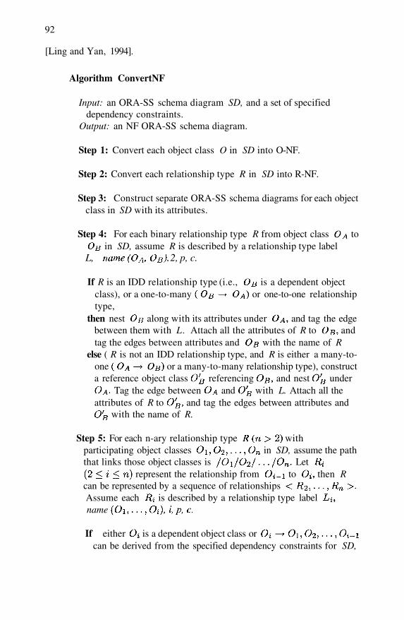
92
[Ling and Yan, 1994].
Algorithm ConvertNF
Input: an ORA-SS schema diagram SD, and a set of specifieddependency constraints.
Output: an NF ORA-SS schema diagram.
Step 1: Convert each object class O in SD into O-NF.
Step 2: Convert each relationship type R in SD into R-NF.
Step 3: Construct separate ORA-SS schema diagrams for each objectclass in SD with its attributes.
Step 4: For each binary relationship type R from object class toin SD, assume R is described by a relationship type label
L, 2, p, c.
If R is an IDD relationship type (i.e., is a dependent objectclass), or a one-to-many or one-to-one relationshiptype,
then nest along with its attributes under and tag the edgebetween them with L. Attach all the attributes of R to andtag the edges between attributes and with the name of R
else ( R is not an IDD relationship type, and R is either a many-to-one or a many-to-many relationship type), constructa reference object class referencing and nest under
Tag the edge between and with L. Attach all theattributes of R to and tag the edges between attributes and
with the name of R.
Step 5: For each n-ary relationship type withparticipating object classes in SD, assume the paththat links those object classes is Let
represent the relationship from to then Rcan be represented by a sequence of relationshipsAssume each is described by a relationship type labelname
If either is a dependent object class orcan be derived from the specified dependency constraints for SD,
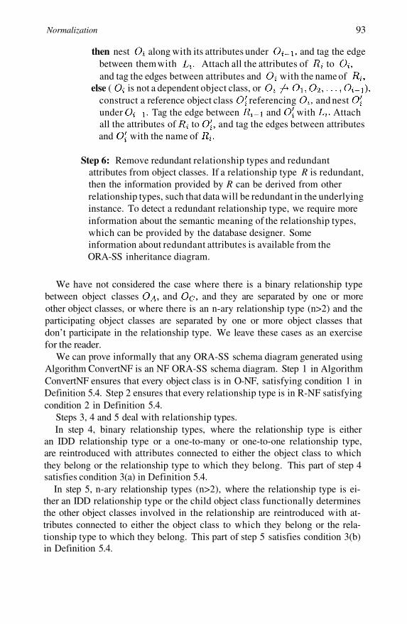
Normalization 93
then nest along with its attributes under and tag the edgebetween them with Attach all the attributes of toand tag the edges between attributes and with the name of
else ( is not a dependent object class, orconstruct a reference object class referencing and nestunder Tag the edge between and with Attachall the attributes of to and tag the edges between attributesand with the name of
Step 6: Remove redundant relationship types and redundantattributes from object classes. If a relationship type R is redundant,then the information provided by R can be derived from otherrelationship types, such that data will be redundant in the underlyinginstance. To detect a redundant relationship type, we require moreinformation about the semantic meaning of the relationship types,which can be provided by the database designer. Someinformation about redundant attributes is available from theORA-SS inheritance diagram.
We have not considered the case where there is a binary relationship typebetween object classes and and they are separated by one or moreother object classes, or where there is an n-ary relationship type (n>2) and theparticipating object classes are separated by one or more object classes thatdon’t participate in the relationship type. We leave these cases as an exercisefor the reader.
We can prove informally that any ORA-SS schema diagram generated usingAlgorithm ConvertNF is an NF ORA-SS schema diagram. Step 1 in AlgorithmConvertNF ensures that every object class is in O-NF, satisfying condition 1 inDefinition 5.4. Step 2 ensures that every relationship type is in R-NF satisfyingcondition 2 in Definition 5.4.
Steps 3, 4 and 5 deal with relationship types.In step 4, binary relationship types, where the relationship type is either
an IDD relationship type or a one-to-many or one-to-one relationship type,are reintroduced with attributes connected to either the object class to whichthey belong or the relationship type to which they belong. This part of step 4satisfies condition 3(a) in Definition 5.4.
In step 5, n-ary relationship types (n>2), where the relationship type is ei-ther an IDD relationship type or the child object class functionally determinesthe other object classes involved in the relationship are reintroduced with at-tributes connected to either the object class to which they belong or the rela-tionship type to which they belong. This part of step 5 satisfies condition 3(b)in Definition 5.4.

94
In step 4, binary relationship types, where the relationship type is a many-to-one or many-to-many relationship type are addressed by creating a new objectclass and including a reference between the original child object class and thenew object class. The attributes are connected to either the object class orrelationship type to which they belong.
In step 5, n-ary relationship types (n>2), where the child object class is nota dependent object class and the child object class does not functionally deter-mine the other object classes involved in the relationship type are addressed bycreating a new object class and introducing a reference between the originalchild object class and the new object class. These parts of steps 4 and 5 satisfycondition 4 in Definition 5.4.
Step 6 deals with redundant relationship types and redundant object classes,and satisfies condition 5 of Definition 5.4.
Hence all conditions in Definition 5.4 are satisfied, so any ORA-SS schemadiagram generated using Algorithm ConvertNF is an NF ORA-SS schema di-agram.
We illustrate Algorithm ConvertNF in the following five examples. Exam-ple 5.7 illustrates how many-to-many relationship types are dealt with in thealgorithm. Example 5.8 demonstrates a ternary relationship type. Example 5.9demonstrates how the algorithm deals with object classes that are not alreadyin O-NF, while Example 5.10 contains an IDD relationship type, and Exam-ple 5.11 contains attributes that can be derived from other attributes.
Example 5.7 Consider the ORA-SS schema diagram in Figure 5.10(a). Thereis a many-to-many binary relationship type lc between lecturer and course,and a many-to-many binary relationship type ct between course and textbook.There is an attribute feedback that belongs to relationship type lc.
Step 1: We consider each object class individually. The nested relationsformed for the object class lecturer, course, and textbook are
Each nested relation is in NF-NR so each object class lecturer, course and text-book is in O-NF.
Step 2: We consider each relationship type individually. The nested rela-tions formed for the relationship types lc and ct are
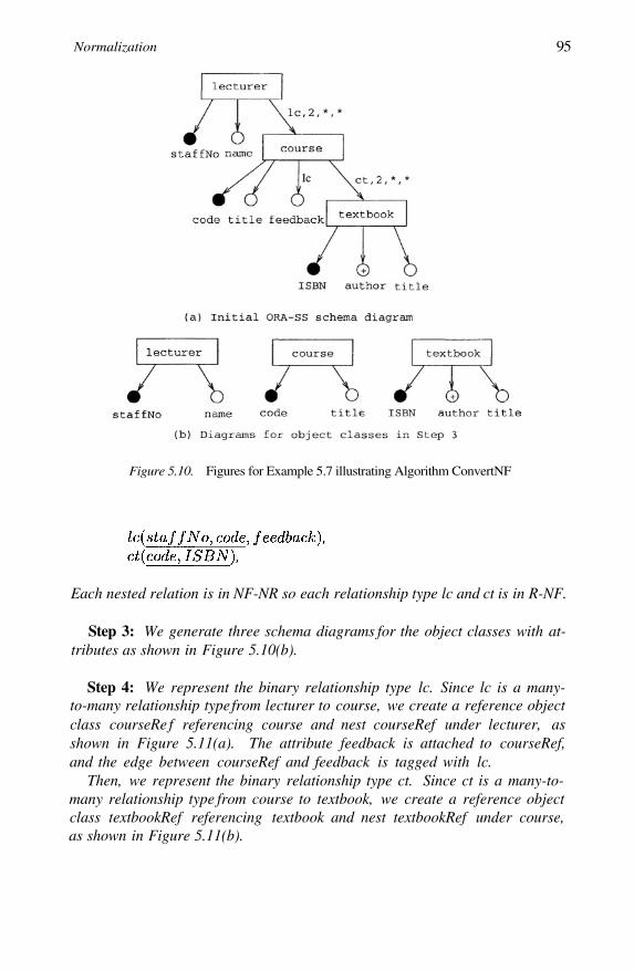
Normalization 95
Figure 5.10. Figures for Example 5.7 illustrating Algorithm ConvertNF
Each nested relation is in NF-NR so each relationship type lc and ct is in R-NF.
Step 3: We generate three schema diagrams for the object classes with at-tributes as shown in Figure 5.10(b).
Step 4: We represent the binary relationship type lc. Since lc is a many-to-many relationship type from lecturer to course, we create a reference objectclass courseRe f referencing course and nest courseRef under lecturer, asshown in Figure 5.11(a). The attribute feedback is attached to courseRef,and the edge between courseRef and feedback is tagged with lc.
Then, we represent the binary relationship type ct. Since ct is a many-to-many relationship type from course to textbook, we create a reference objectclass textbookRef referencing textbook and nest textbookRef under course,as shown in Figure 5.11(b).
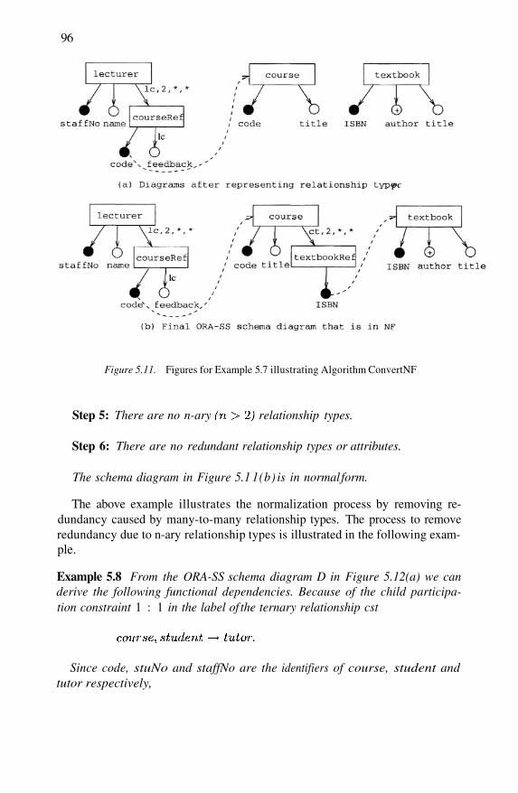
96
Figure 5.11. Figures for Example 5.7 illustrating Algorithm ConvertNF
Step 5: There are no n-ary relationship types.
Step 6: There are no redundant relationship types or attributes.
The schema diagram in Figure 5.1 1(b) is in normal form.
The above example illustrates the normalization process by removing re-dundancy caused by many-to-many relationship types. The process to removeredundancy due to n-ary relationship types is illustrated in the following exam-ple.
Example 5.8 From the ORA-SS schema diagram D in Figure 5.12(a) we canderive the following functional dependencies. Because of the child participa-tion constraint 1 : 1 in the label of the ternary relationship cst
Since code, stuNo and staffNo are the identifiers of course, student andtutor respectively,
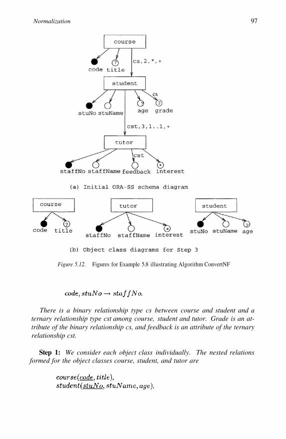
Normalization 97
Figure 5.12. Figures for Example 5.8 illustrating Algorithm ConvertNF
There is a binary relationship type cs between course and student and aternary relationship type cst among course, student and tutor. Grade is an at-tribute of the binary relationship cs, and feedback is an attribute of the ternaryrelationship cst.
Step 1: We consider each object class individually. The nested relationsformed for the object classes course, student, and tutor are
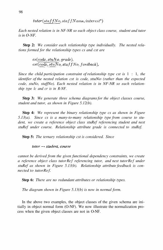
98
Each nested relation is in NF-NR so each object class course, student and tutoris in O-NF.
Step 2: We consider each relationship type individually. The nested rela-tions formed for the relationship types cs and cst are
Since the child participation constraint of relationship type cst is 1 : 1, theidentifier of the nested relation cst is code, stuNo (rather than the expectedcode, stuNo, staffNo). Each nested relation is in NF-NR so each relation-ship type lc and cr is in R-NF.
Step 3: We generate three schema diagrams for the object classes course,student and tutor, as shown in Figure 5.12(b).
Step 4: We represent the binary relationship type cs as shown in Figure5.13(a). Since cs is a many-to-many relationship type from course to stu-dent, we create a reference object class stuRef referencing student and neststuRef under course. Relationship attribute grade is connected to stuRef.
Step 5: The ternary relationship cst is considered. Since
cannot be derived from the given functional dependency constraints, we createa reference object class tutor Re f referencing tutor, and nest tutor Re f understuRef as shown in Figure 5.13(b). Relationship attribute feedback is con-nected to tutor Re f.
Step 6: There are no redundant attributes or relationship types.
The diagram shown in Figure 5.13(b) is now in normal form.
In the above two examples, the object classes of the given schema are ini-tially in object normal form (O-NF). We now illustrate the normalization pro-cess when the given object classes are not in O-NF.

Normalization 99
Figure 5.13. Figures for Example 5.8 illustrating Algorithm ConvertNF
Example 5.9 Consider the object class student given in Figure 5.14(a). Wehave the following functional dependency:
From the diagram, we have:
Step 1: Consider the nested relation formed from the attributes of objectclass student,
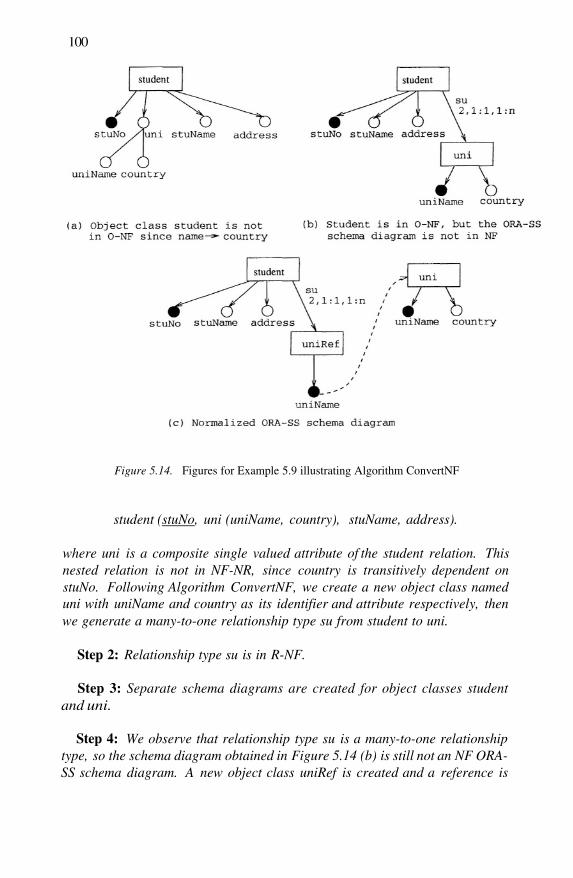
100
Figure 5.14. Figures for Example 5.9 illustrating Algorithm ConvertNF
student (stuNo, uni (uniName, country), stuName, address).
where uni is a composite single valued attribute of the student relation. Thisnested relation is not in NF-NR, since country is transitively dependent onstuNo. Following Algorithm ConvertNF, we create a new object class nameduni with uniName and country as its identifier and attribute respectively, thenwe generate a many-to-one relationship type su from student to uni.
Step 2: Relationship type su is in R-NF.
Step 3: Separate schema diagrams are created for object classes studentand uni.
Step 4: We observe that relationship type su is a many-to-one relationshiptype, so the schema diagram obtained in Figure 5.14 (b) is still not an NF ORA-SS schema diagram. A new object class uniRef is created and a reference is
Normalization 101
introduced between uniRef and uni.
Steps 5 and 6: There are no n-ary relationships in the ORA-SS diagram,and no redundant attributes or relationship types.
The final result shown in Figure 5.14(c) is now in normal form.
Next, we illustrate the process of transforming an ORA-SS schema with anIDD relationship type into its normal form.
Example 5.10 Consider the ORA-SS schema diagram in Figure 5.15(a), withan IDD binary relationship type from employee to dependent. We have the fol-lowing functional dependency:
Step 1: Consider the nested relation formed from the attributes of objectclass employee,
This nested relation is not in NF-NR, since schoolAddress is transitively de-pendent on {staffNo, depName}. Following Algorithm ConvertNF, we cre-ate a new object class named school with school and schoolAddress as itsidentifier and attribute respectively, then we generate a many-to-one relation-ship type ds from dependent to school, as shown in Figure 5.15(b).
Step 2: Relationship type ds is in R-NF.
Step 3: Separate schema diagrams are created for object classes employeeand school.
Step 4: We observe that relationship type ds is a many-to-one relationshiptype, so the schema diagram obtained in Figure 5.15 (b) is still not an NF ORA-SS schema diagram. A new object class schoolRef is created and a referenceis introduced between schoolRef and school.
Steps 5 and 6: There are no n-ary relationships in the ORA-SS diagram,and no redundant attributes or relationship types.
The final example illustrates normalization of an ORA-SS diagram withredundant attributes.
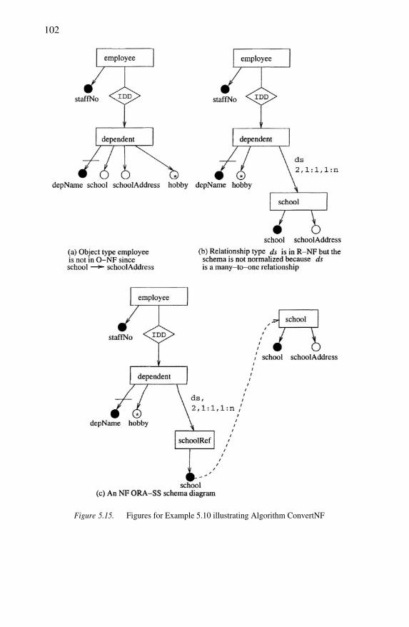
102
Figure 5.15. Figures for Example 5.10 illustrating Algorithm ConvertNF
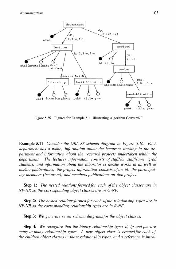
Normalization 103
Figure 5.16. Figures for Example 5.11 illustrating Algorithm ConvertNF
Example 5.11 Consider the ORA-SS schema diagram in Figure 5.16. Eachdepartment has a name, information about the lecturers working in the de-partment and information about the research projects undertaken within thedepartment. The lecturer information consists of staffNo, staffName, gradstudents, and information about the laboratories he/she works in as well ashis/her publications; the project information consists of an id, the participat-ing members (lecturers), and members publications on that project.
Step 1: The nested relations formed for each of the object classes are inNF-NR so the corresponding object classes are in O-NF.
Step 2: The nested relations formed for each of the relationship types are inNF-NR so the corresponding relationship types are in R-NF.
Step 3: We generate seven schema diagrams for the object classes.
Step 4: We recognize that the binary relationship types ll, lp and pm aremany-to-many relationship types. A new object class is created for each ofthe children object classes in these relationship types, and a reference is intro-

104

Normalization 105
Figure 5.18. Figures for Example 5.11 illustrating Algorithm ConvertNF
duced between the new object class and the original.
Step 5: We recognize that in the ternary relationship type pmp (in Figure5.16)
so we generate an object class memPubRef under memberRef, and let theobject class memPubRef reference memPublication as shown in Figure 5.17.
Step 6: The members of projects are lecturers and research assistants, sothe details of lecturers will not only be stored in a relationship with depart-ment objects but also in a relationship with project objects. In order to re-move this replication a new object class is created which is referenced by bothmember and lecturer. However, because the new object class has the sameattributes as the object class member (as shown in the inheritance diagramin Figure 5.18), we are able to replace the new object class with a referenceobject class member.
Because some of the lecturers are members of projects, some publicationsthat are instances of memPublication are also instances of lectPublication.
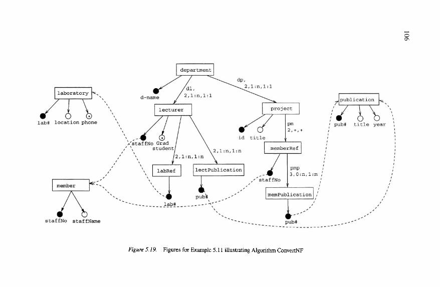
106

Normalization 107
In order to remove this replication a new object class is created which is refer-enced by both memPublication and lectPublication. Because the object classpublication has the same attributes as both object classes lectPublicationand memPublication (as shown in Figure 5.18), we are able to remove bothobject classes. If all the publications of lecturers were published by membersof a project, then we could remove lectPublication. However, since some lec-turers may not work on projects or may have publications other than those thatare published as part of a project, we retain lectPublication.
The ORA-SS schema diagram shown in Figure 5.19 is now in normal form.
5.5 Discussion
In a survey which takes a database-centric view of XML, [Widom, 1999]noted that the concept of functional dependencies in the context of XML hasnot been explored.
However, keys, which are a special case of functional dependencies, arestudied in the context of XML by [Buneman et al., 2001a]. It offers two basicdefinitions for keys in XML : strong keys and weak keys. If a key is a strongkey, then given a set of elements, each element in the set must have a pathto the key node, and the value of the key node must be unique. If a key is aweak key, then given a set of elements, for each element in the set, if there is apath to the key node then the value of the key node must be unique. Consideran XML document in which it is not mandatory for every person to have adriving licence number but if they do, then the number is unique. The drivinglicence number is then a weak key, but not a strong key. Weak key paths can bemissing, which makes weak keys similar to null-valued keys in the relationalcontext. [Buneman et al., 2001a] also noted that there are many other possibledefinitions for keys, and introduced the concept of relative keys. Noting thatkeys in many data formats (e.g. scientific databases) have a hierarchical struc-ture, relative keys provide hierarchical key structures to accommodate suchdatabases. Consider an XML document that contains information about stu-dents enrolled in courses, assuming that a student can enroll in a course onlyonce then the student number is a key relative to the course. Such structuresare similar to the notion of ID dependent relationships in Entity Relationshipdiagrams.
[Fan and Simeon, 2000] proposed constraint languages to capture seman-tics of XML documents using simply key, foreign key and inverse constraints.However, functional dependencies, which form the theoretic foundation forkeys, were not addressed in these works.
The concept of allowing controlled data redundancy in exchange for fasterprocessing was introduced in [Ling et al., 1996]. In Chapter 7, we presentanalogous arguments in the XML context for allowing controlled data redun-
dancy. Preliminary work has also been done on semantics preservation whentranslating data between the relational tables and XML [Lee and Chu, 2000].
Normal forms defined for relational databases, both 3NF, BCNF, 4NF and5NF for the flat relational model, and nested relational normal forms likeNNF [Ozsoyoglu and Yuan, 1987] and NF-NR [Ling and Yan, 1994] have beenstudied intensively in the past two decades. However, the above normal formsfor traditional data models are not directly applicable to semistructured data forthe following reasons. First, the semistructured data model is richer and morecomplex than the relational data model. For example, XML incorporates car-dinality constraints that are not found in the relational data model. Second, insemistructured data, the schema is descriptive, rather than prescriptive. Henceno regular structure is expected in semistructured data instances.
We mentioned in this chapter that ORA-SS bears some similarity to nestedrelations, in that both have a tree-like structure and allow repeating groupsor multiple occurrences of objects, and that such correspondence allows us tomap an ORA-SS schema diagram to nested relations. However, ORA-SS isdifferent from nested relations in the following significant ways: First, ORA-SS defines relationship types that are not available in nested relations. Second,reference is one of the four main concepts defined in ORA-SS schema dia-grams, while it is represented using foreign keys in nested relations. Thesedifferences in the data models determine the differences in their normal formdefinition as well as their design methods.
The first work to investigate the problem of normalization in semistructuredschemas is presented in [Lee et al., 1999]. It defines an S3-NF normal formfor S3-Graph (or SemiStructured Schema Graph), which is basically a labeledgraph in which vertices correspond to objects and edges represent the object-subobject relationships. Unlike the ORA-SS schema diagram, the S3-Graphis not able to model the semantics traditionally needed for recognizing redun-dancy in databases. For example, it cannot show the degree of an n-ary re-lationship type; neither can it distinguish between attributes of object classesand attributes of relationship types. To identify redundancy in an S3-Graph,[Lee et al., 1999] define a dependency constraint called SS-Dependency. AnS3-Graph is in S3-NF if there is no transitive SS-dependency. Hence, only alimited kind of redundancy can be recognized by S3-NF. In [Lee et al., 1999],the authors present two approaches for designing S3-NF databases. One is adecomposition method, which can transform the schema to reduce redundancybased on SS-dependency. This decomposition may not always remove all tran-sitive functional dependencies. The other method is to transform a normal formER diagram [Lee et al., 1999] into an S3-Graph. Although the result obtainedis in S3-NF, it is not unique and is dependent on the path taken to construct it.
108

Normalization 109
Therefore, the result may not satisfy the application requirements or complywith the user’s viewpoints.
In [Wu et al., 2001b], we propose a normal form for the semistructuredschema called NF-SS, which extends S3-NF. NF-SS involves the XML modelwith integrity constraints, such as extended functional dependency (EFD) andkey constraints. The NF-SS model improves on S3-Graphs by providing thenotion of objects and attributes, and specifying cardinality on the schema.However, the NF-SS model still has no concept of composite attributes, andno distinction between relationship type attributes and object class attributes.A major difference between NF ORA-SS and NF-SS is that NF-SS does notdeal with relationship types, as they are not available in its data model defini-tion. A semistructured schema is in NF-SS, if it has no transitive or partial EFDand incoherent EFD. This is recursively defined by requiring the componentsof every object type (starting from the root and then proceeding downward)should not be transitively dependent on their parents, and should be as nearto their owners as possible. Since the semantic information expressed by thedata model is very limited, the NF-SS definition identifies redundancy mainlythrough the specified EFDs for the schema. In [Wu et al., 2001b], we proposea restructuring approach to design NF-SS. We develop an iterative algorithmbased on a set of heuristic rules to restructure a semistructured schema intoa normal form. The restructuring involves the decomposition of object types,creation of new object types and regrouping of components in a semistructuredschema. The objective is to remove transitive or partial EFD and incoherentEFD, and is accomplished by identifying violations of the conditions of NF-SSgiven the dependency and key constraints. Similar to the decomposition meth-ods for relational normalization, the NF-SS restructuring approach is not ableto guarantee dependency covering or dependency preservation.
In [Embley and Mok, 2001], the authors propose a normal form for XMLdocument called XNF (XML Normal Form). The process of generating anXNF-compliant DTD follows: it first takes a conceptual model-based method-ology, using CM hypergraphs (conceptual-model hypergraphs), to model anapplication. Then it translates the CM hypergraph M to a scheme-tree forest F.F is in XNF if each scheme tree in F has no potential redundancy with respectto a specified set of (functional and multivalued) constraints C, and F has asfew scheme trees as any other scheme-tree forest corresponding to M in whicheach scheme tree has no potential redundancy with respect to C. Finally, itgenerates a DTD from the scheme-tree. Like S3-Graph, CM hypergraph hasno concept of attributes resulting in too many objects in a schema; in addition,CM hypergraph has no hierarchical structure. The algorithms for translatinga CM hypergraph M to a scheme-tree forest are non-deterministic, and sufferfrom inefficiency. Additionally, adding or deleting required information re-quires a redesign of the whole schema. Further, the algorithms generate a large
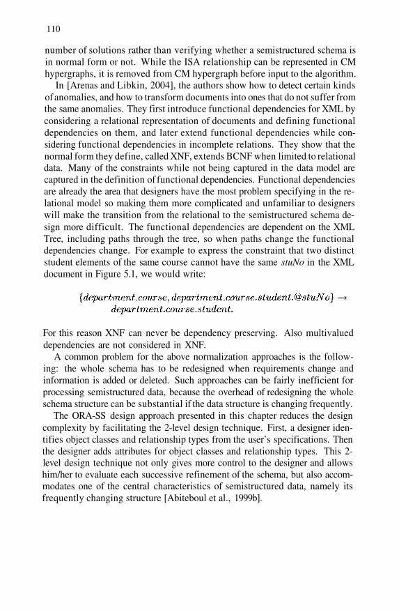
110
number of solutions rather than verifying whether a semistructured schema isin normal form or not. While the ISA relationship can be represented in CMhypergraphs, it is removed from CM hypergraph before input to the algorithm.
In [Arenas and Libkin, 2004], the authors show how to detect certain kindsof anomalies, and how to transform documents into ones that do not suffer fromthe same anomalies. They first introduce functional dependencies for XML byconsidering a relational representation of documents and defining functionaldependencies on them, and later extend functional dependencies while con-sidering functional dependencies in incomplete relations. They show that thenormal form they define, called XNF, extends BCNF when limited to relationaldata. Many of the constraints while not being captured in the data model arecaptured in the definition of functional dependencies. Functional dependenciesare already the area that designers have the most problem specifying in the re-lational model so making them more complicated and unfamiliar to designerswill make the transition from the relational to the semistructured schema de-sign more difficult. The functional dependencies are dependent on the XMLTree, including paths through the tree, so when paths change the functionaldependencies change. For example to express the constraint that two distinctstudent elements of the same course cannot have the same stuNo in the XMLdocument in Figure 5.1, we would write:
For this reason XNF can never be dependency preserving. Also multivalueddependencies are not considered in XNF.
A common problem for the above normalization approaches is the follow-ing: the whole schema has to be redesigned when requirements change andinformation is added or deleted. Such approaches can be fairly inefficient forprocessing semistructured data, because the overhead of redesigning the wholeschema structure can be substantial if the data structure is changing frequently.
The ORA-SS design approach presented in this chapter reduces the designcomplexity by facilitating the 2-level design technique. First, a designer iden-tifies object classes and relationship types from the user’s specifications. Thenthe designer adds attributes for object classes and relationship types. This 2-level design technique not only gives more control to the designer and allowshim/her to evaluate each successive refinement of the schema, but also accom-modates one of the central characteristics of semistructured data, namely itsfrequently changing structure [Abiteboul et al., 1999b].

Chapter 6
VIEWS
XML views are essential for managing XML data on the Web. Just likeviews in traditional databases, XML views provide application-specific viewsof the source data and secure the source data [Abiteboul, 1999].
Several systems have been proposed to support XML views. Systems suchas SilkRoute [Fernandez et al., 2000] and XPERANTO [Carey et al., 2000]provide XML views over relational databases. Others such as Xyleme [Cluetet al., 2001] and Active View [Abiteboul et al., 1999a] allow the definitionof XML views over native XML files. The ActiveView system [Abiteboulet al., 1999a] defines views using the object-oriented approach, which allowsnot only data, but also methods.
XML Views are also used as a middleware in data integration systems suchas MIX [Baru et al., 1999] and MARS [Deutsch and Tannen, 2003]. The MIXsystem [Baru et al., 1999] integrates heterogeneous data sources and offersviews based on the underlying data sources.
While existing systems provide for the definition of XML views, they donot validate the views that are created. Therefore, there is no guarantee that theviews defined are valid.Valid XML Views. Let V be a view defined over an XML data source D.V is said to be valid if it does not violate the semantics, that is, functionaldependencies, relationship types and their degrees (binary, ternary and n-ary),and key and foreign key constraints implied in D.
In this chapter, we describe a systematic approach to ensure the validity ofXML views. We have designed a set of rules to guide the design of valid XMLviews. Section 6.1 gives an example to illustrate the need for view validation.Sections 6.2 to 6.6 describe the various operators for designing views, and therules for ensuring that the view obtained is valid, presents Section 6.7 discussesrelated work and we conclude in section 6.8.
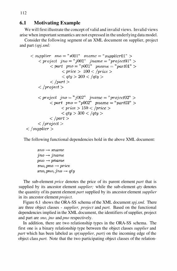
112
6.1 Motivating ExampleWe will first illustrate the concept of valid and invalid views. Invalid views
arise when important semantics are not expressed in the underlying data model.Consider the following segment of an XML document on supplier, project
and part (spj.xml:
The following functional dependencies hold in the above XML document:
The sub-element price denotes the price of its parent element part that issupplied by its ancestor element supplier; while the sub-element qty denotesthe quantity of its parent element part supplied by its ancestor element supplierin its ancestor element project.
Figure 6.1 shows the ORA-SS schema of the XML document spj.xml. Thereare three object classes - supplier, project and part. Based on the functionaldependencies implied in the XML document, the identifiers of supplier, projectand part are sno, jno and pno respectively.
In addition, there are two relationship types in the ORA-SS schema. Thefirst one is a binary relationship type between the object classes supplier andpart which has been labeled as sp(supplier, part) on the incoming edge of theobject class part. Note that the two participating object classes of the relation-
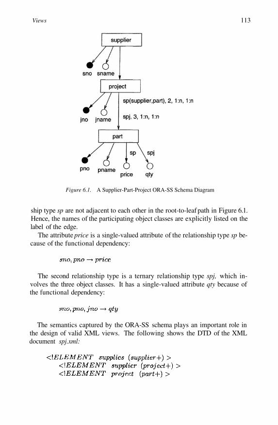
Views 113
Figure 6.1. A Supplier-Part-Project ORA-SS Schema Diagram
ship type sp are not adjacent to each other in the root-to-leaf path in Figure 6.1.Hence, the names of the participating object classes are explicitly listed on thelabel of the edge.
The attribute price is a single-valued attribute of the relationship type sp be-cause of the functional dependency:
The second relationship type is a ternary relationship type spj, which in-volves the three object classes. It has a single-valued attribute qty because ofthe functional dependency:
The semantics captured by the ORA-SS schema plays an important role inthe design of valid XML views. The following shows the DTD of the XMLdocument spj.xml:

114
Note that we cannot express jno and pno as the ID of the elements supplierand part respectively in the DTD. This is because these elements are involvedin a many-to-many relationship with project and will occur multiple times inan XML document.
We observe that the elements price and qty are represented in the same man-ner as the elements supplier and part. In other words, the DTD cannot expressthe two functional dependencies:
Further, the DTD also cannot differentiate object class, attribute and rela-tionship type.
Let us now design a view that swaps the hierarchical positions of the el-ements project and part. That is, project becomes a child of part and partbecomes the parent of project. Obviously, the attributes pno and pname of theobject class part will move up together with part since they are properties ofpart. Similarly, the attributes jno and jname of object class project will movedown with project.
A possible view as shown in Figure 6.2 is created. Since the DTD XMLdoes not explicitly express the functional dependencies involving price andqty, these elements have also moved up together with part. This is an invalidview because it violates the functional dependency in the source document:
The problem of invalid view can be resolved by utilizing the ORA-SS model.Based on the ORA-SS source schema in Figure 6.1, we can design a valid viewthat swaps project and part (see Figure 6.3).
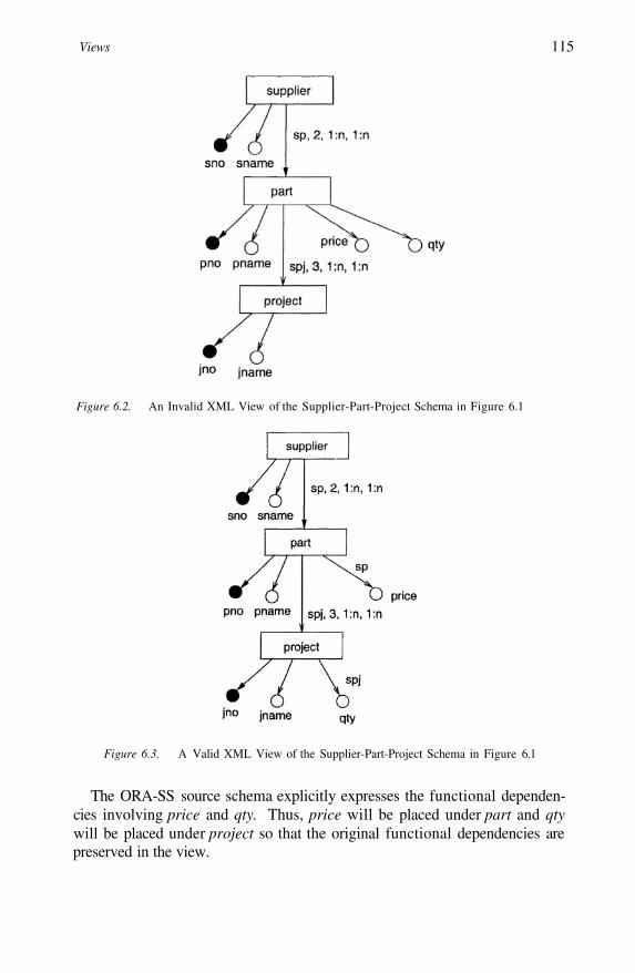
Views 115
Figure 6.2. An Invalid XML View of the Supplier-Part-Project Schema in Figure 6.1
Figure 6.3. A Valid XML View of the Supplier-Part-Project Schema in Figure 6.1
The ORA-SS source schema explicitly expresses the functional dependen-cies involving price and qty. Thus, price will be placed under part and qtywill be placed under project so that the original functional dependencies arepreserved in the view.
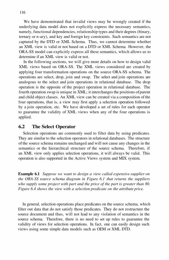
116
We have demonstrated that invalid views may be wrongly created if theunderlying data model does not explicitly express the necessary semantics,namely, functional dependencies, relationship types and their degrees (binary,ternary or n-ary), and key and foreign key constraints. Such semantics are notcaptured by the DTD or XML Schema. Thus, we cannot determine whetheran XML view is valid or not based on a DTD or XML Schema. However, theORA-SS model can explicitly express all these semantics, which allows us todetermine if an XML view is valid or not.
In the following sections, we will give more details on how to design validXML views based on ORA-SS. The XML views considered are created byapplying four transformation operations on the source ORA-SS schema. Theoperations are select, drop, join and swap. The select and join operations areanalogous to the select and join operations in relational database. The dropoperation is the opposite of the project operation in relational database. Thefourth operation swap is unique in XML; it interchanges the positions of parentand child object classes. An XML view can be created via a composition of thefour operations, that is, a view may first apply a selection operation followedby a join operation, etc. We have developed a set of rules for each operatorto guarantee the validity of XML views when any of the four operations isapplied.
6.2 The Select OperatorSelection operations are commonly used to filter data by using predicates.
They are similar to the selection operators in relational databases. The structureof the source schema remains unchanged and will not cause any changes in thesemantics or the hierarchical structure of the source schema. Therefore, ifan XML view only applies selection operations, it will always be valid. Thisoperation is also supported in the Active Views system and MIX system.
Example 6.1 Suppose we want to design a view called expensive-supplier onthe ORA-SS source schema diagram in Figure 6.1 that returns the supplierswho supply some project with part and the price of the part is greater than 80.Figure 6.4 shows the view with a selection predicate on the attribute price.
In general, selection operations place predicates on the source schema, whichfilter out data that do not satisfy those predicates. They do not restructure thesource document and thus, will not lead to any violation of semantics in thesource schema. Therefore, there is no need to set up rules to guarantee thevalidity of views for selection operations. In fact, one can easily design suchviews using some simple data models such as OEM or XML DTD.
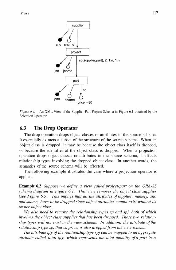
Views 117
Figure 6.4. An XML View of the Supplier-Part-Project Schema in Figure 6.1 obtained by theSelection Operator
6.3 The Drop OperatorThe drop operation drops object classes or attributes in the source schema.
It essentially extracts a subset of the structure of the source schema. When anobject class is dropped, it may be because the object class itself is dropped,or because the identifier of the object class is dropped. When a projectionoperation drops object classes or attributes in the source schema, it affectsrelationship types involving the dropped object class. In another words, thesemantics of the source schema will be affected.
The following example illustrates the case where a projection operator isapplied.
Example 6.2 Suppose we define a view called project-part on the ORA-SSschema diagram in Figure 6.1. This view removes the object class supplier(see Figure 6.5). This implies that all the attributes of supplier, namely, snoand sname, have to be dropped since object attributes cannot exist without itsowner object class.
We also need to remove the relationship types sp and spj, both of whichinvolves the object class supplier that has been dropped. These two relation-ship types will not exist in the view schema. In addition, the attribute of therelationship type sp, that is, price, is also dropped from the view schema.
The attribute qty of the relationship type spj can be mapped to an aggregateattribute called total-qty, which represents the total quantity of a part in a
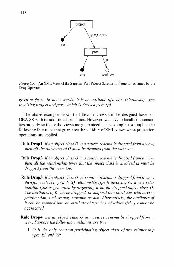
118
Figure 6.5. An XML View of the Supplier-Part-Project Schema in Figure 6.1 obtained by theDrop Operator
given project. In other words, it is an attribute of a new relationship typeinvolving project and part, which is derived from spj.
The above example shows that flexible views can be designed based onORA-SS with its additional semantics. However, we have to handle the seman-tics properly so that valid views are guaranteed. This example also implies thefollowing four rules that guarantee the validity of XML views when projectionoperations are applied.
Rule Drop1. If an object class O in a source schema is dropped from a view,then all the attributes of O must be dropped from the view too.
Rule Drop2. If an object class O in a source schema is dropped from a view,then all the relationship types that the object class is involved in must bedropped from the view too.
Rule Drop3. If an object class O in a source schema is dropped from a view,then for each relationship type R involving O, a new rela-tionship type is generated by projecting R on the dropped object class O.The attributes of R can be dropped, or mapped into attributes with aggre-gate function, such as avg, max/min or sum. Alternatively, the attributes ofR can be mapped into an attribute of type bag of values if they cannot beaggregated.
Rule Drop4. Let an object class O in a source schema be dropped from aview. Suppose the following conditions are true:
1 O is the only common participating object class of two relationshiptypes R1 and R2;
Views 119
2
3
All the participating object classes of R1 and R2 are in a continualpath;The participating object classes of R1 is not a subset of the participat-ing object classes of R2 and vice versa.
Then a new relationship type can be obtained by joining R1 and R2 basedon the object class O.
We will now discuss each of the four rules in details and demonstrate whythey are able to guarantee the validity of XML views.
RULE DROP1
Intuitively, Rule Drop1 indicates that we cannot leave an attribute in theview if its owner object class has been dropped from the view. Without theirobject class, the attributes will lose their meaning.
RULE DROP2
Rule Drop2 handles the situation when one participating object class of arelationship type is dropped in the view, in which case the relationship typeis broken up. Although the relationship type will not be shown in an XMLdocument or an XML schema, it needs to be dropped to keep the semantics inthe ORA-SS view schema consistent.
After a relationship type has been dropped, the rest of the object classes in-volved in the relationship type still have semantic connections in the view. Inorder to maintain these semantic connection in the view, we can derive a newrelationship type from the relationship type that has been dropped. This givesus the Rule Drop3.
RULE DROP3
Suppose object classes participate in a relationship type R ina source schema. Let us assume that one of the object classes, say
is dropped from a view. According to Rule Proj3, a new relationship typeR’ can be derived from R by projecting out and all the attributes of R, thatis, all the object classes of R except for are kept in the new relationship typeR’.
It is clear that R’ will not violate the semantics implied in R according tothe theory of relational database. Instead, it is able to maintain the semanticconnection among the object classes in the view.
The attributes of R can be dropped from the view. Alternatively, new at-tributes can be derived according to the Rule Drop3. The new derived attributesremain valid in the view schema.

120
This approach correctly maintains the semantics among the remaining ob-ject classes of the relationship type R.
RULE DROP4
The above three rules are not sufficient when the object class that has beendropped from the view is involved in more than one relationship type in thesource schema. In such situations, we need to join these relationship types inorder to maintain the semantic connection among them.
Rule Drop4 contains additional conditions besides the project operator it-self. We will show why these conditions are important.
Let us assume that the first condition does not hold, that is, R1 and R2 haveother common object classes. In this case, it is clear that we do not have to joinR1 and R2 since the semantic connection between R1 and R2 is still explicitlyexpressed through the other common object classes.
Next, suppose the second condition is false, that is, all the participatingobject classes of R1 and R2 do not lie in the same path. In this case, we cannotjoin R1 and R2 since the object classes of the new relationship type will not bein the same path, and the new relationship type will be meaningless.
Finally, suppose that the third condition is false. Then either all participatingobject classes of R1 participate in R2 or vice versa. In this situation, if the onlycommon object class of R1 and R2 is dropped, then all the object classes of R1must have been removed in the view schema. Thus, we do not need to join R1and R2 in the view schema.
The view designed using Rule Drop4 is valid. Suppose object classesparticipate in the relationship type Rl in the order from ancestor to
descendant, and object class participate in the relationshiptype R2 in the order from ancestor to descendant in the source schema. Thenthe relationship types R1 and R2 are in the same path in the schema, and theydo not contain each other. Suppose that and are the same object classand this object class is the only object class that is common to R1 and R2, andthis object class is dropped from the view.
Since all the conditions in Rule Drop4 are satisfied, we can derive a newrelationship type R’ in the view schema by joining R1 and R2. Obviously, thederived relationship type R’ maintains the semantic connection among the tworelationship types, and does not violate the semantics of R1 and R2 accord-ing to the theory of relational database. Therefore, the semantics among theremaining object classes that participate in R1 and R2 in the view is correctlykept and the view is valid.
The following example illustrates how Rule Drop4 is applied to ensure thevalidity of a view.
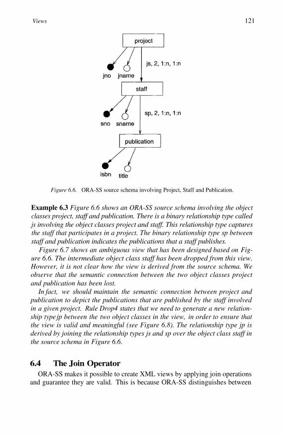
Views 121
Figure 6.6. ORA-SS source schema involving Project, Staff and Publication.
Example 6.3 Figure 6.6 shows an ORA-SS source schema involving the objectclasses project, staff and publication. There is a binary relationship type calledjs involving the object classes project and staff. This relationship type capturesthe staff that participates in a project. The binary relationship type sp betweenstaff and publication indicates the publications that a staff publishes.
Figure 6.7 shows an ambiguous view that has been designed based on Fig-ure 6.6. The intermediate object class staff has been dropped from this view.However, it is not clear how the view is derived from the source schema. Weobserve that the semantic connection between the two object classes projectand publication has been lost.
In fact, we should maintain the semantic connection between project andpublication to depict the publications that are published by the staff involvedin a given project. Rule Drop4 states that we need to generate a new relation-ship type jp between the two object classes in the view, in order to ensure thatthe view is valid and meaningful (see Figure 6.8). The relationship type jp isderived by joining the relationship types js and sp over the object class staff inthe source schema in Figure 6.6.
6.4 The Join OperatorORA-SS makes it possible to create XML views by applying join operations
and guarantee they are valid. This is because ORA-SS distinguishes between

122
Figure 6.7. An ambiguous view of Figure 6.6.
Figure 6.8. A valid view of Figure 6.6. The new relationship type jp is derived by joining jsand sp.
object classes and attributes so that two object classes can be joined. Further-more, ORA-SS differentiates between attributes of object classes and attributesof relationship types so that attributes of relationship types will not be treatedas attributes of the joined object class improperly. These features of ORA-SSare not offered by other existing semistructured data model, which will notallow the design of such views.
A standard join operation joins object classes and their attributes together bykey - foreign key references. Referencing object classes and referenced objectclasss may occur in an ORA-SS source diagram or in two ORA-SS sourcediagrams. The former has an attribute that is actually the OID of the latterobject class. Therefore, the former is able to refer to the latter by the attribute,which plays the role of a foreign key.
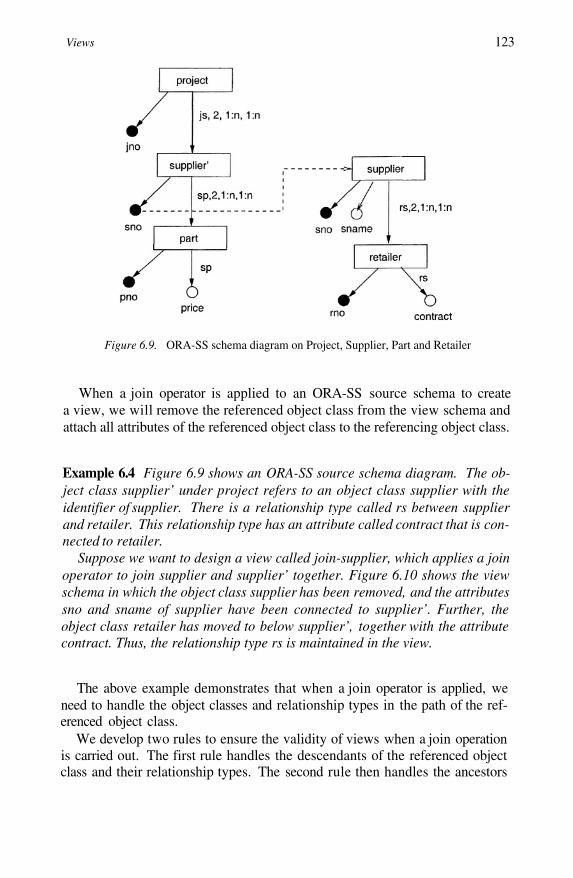
Views 123
Figure 6.9. ORA-SS schema diagram on Project, Supplier, Part and Retailer
When a join operator is applied to an ORA-SS source schema to createa view, we will remove the referenced object class from the view schema andattach all attributes of the referenced object class to the referencing object class.
Example 6.4 Figure 6.9 shows an ORA-SS source schema diagram. The ob-ject class supplier’ under project refers to an object class supplier with theidentifier of supplier. There is a relationship type called rs between supplierand retailer. This relationship type has an attribute called contract that is con-nected to retailer.
Suppose we want to design a view called join-supplier, which applies a joinoperator to join supplier and supplier’ together. Figure 6.10 shows the viewschema in which the object class supplier has been removed, and the attributessno and sname of supplier have been connected to supplier’. Further, theobject class retailer has moved to below supplier’, together with the attributecontract. Thus, the relationship type rs is maintained in the view.
The above example demonstrates that when a join operator is applied, weneed to handle the object classes and relationship types in the path of the ref-erenced object class.
We develop two rules to ensure the validity of views when a join operationis carried out. The first rule handles the descendants of the referenced objectclass and their relationship types. The second rule then handles the ancestors
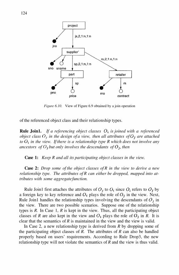
124
Figure 6.10. View of Figure 6.9 obtained by a join operation
of the referenced object class and their relationship types.
Rule Join1. If a referencing object classes is joined with a referencedobject class in the design of a view, then all attributes of are attachedto in the view. If there is a relationship type R which does not involve anyancestors of but only involves the descendants of then
Case 1: Keep R and all its participating object classes in the view.
Case 2: Drop some of the object classes of R in the view to derive a newrelationship type. The attributes of R can either be dropped, mapped into at-tributes with some aggregate function.
Rule Join1 first attaches the attributes of to since refers to bya foreign key to key reference and plays the role of in the view. Next,Rule Join1 handles the relationship types involving the descendants of inthe view. There are two possible scenarios. Suppose one of the relationshiptypes is R. In Case 1, R is kept in the view. Thus, all the participating objectclasses of R are also kept in the view and plays the role of in R. It isclear that the semantics of R is maintained in the view and the view is valid.
In Case 2, a new relationship type is derived from R by dropping some ofthe participating object classes of R. The attributes of R can also be handledproperly based on users’ requirements. According to Rule Drop3, the newrelationship type will not violate the semantics of R and the view is thus valid.

Views 125
On the other hand, we also need to handle the ancestors of in the sourceschema and their relationship types, especially when the ancestors of par-ticipates in a relationship type with or its descendants. Rule Join2 handlesthis situation.
Rule Join2. If a referencing object class is joined with a referenced objectclass in designing a view, then all the attributes of are attached to inthe view. If there is a relationship type R involving the ancestors of then
Case 1: Keep R in the view and swap the ancestors of involving R below
Case 2: Drop the ancestors of involving R in the view to derive a newrelationship type. The attributes of R can be dropped or mapped into attributeswith some aggregate function.
Rule Join2 handles the relationship types that involve the ancestors ofin the view. There are two possible cases when processing these relationshiptypes. Suppose one of the relationship types is R. In Case 1, R and the an-cestors of participating in R are needed in the view schema. Thus, theancestors must be swapped first and become the descendants of so that theycan be attached as descendants in the view schema. In this way, R is keptintact in the view and the view is still valid. Notice a new operator, i.e. swapoperator is utilized in this case. More details on the swap operator will be givenin the following section.
In Case 2, we simply drop all the ancestors of involving R in the view. Asthe ancestors of are already in the view, the ancestors of in the sourceschema cannot appear as ancestors of in the view. After dropping theseancestors, a new relationship type can be derived from R and the attributes canbe handled properly in the view schema. In this way, we can ensure that theview designed will be valid.
6.5 The Swap OperatorThe swap operation restructures the source schema by exchanging the po-
sitions of a parent object class and its child object class. Swap operations areunique in XML because they can be applied only in hierarchical structure. Fur-ther, the swap operator also raises the issue of view reversibility. That is, whenwe swap two object classes to construct a view schema, we can reconstructthe original source schema from the view by carrying out a reverse swapping.Therefore, we require not only rules to design valid views, but also rules toguarantee that the designed views are reversible.
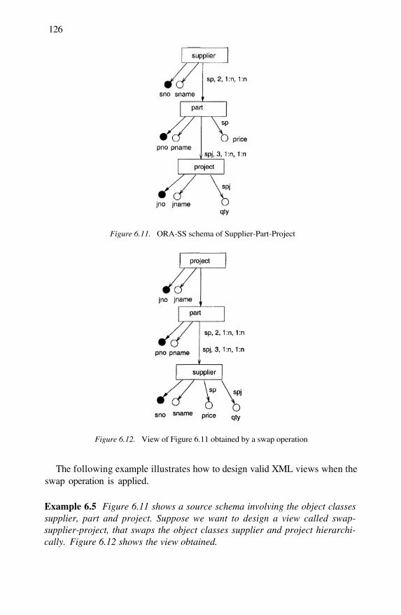
126
Figure 6.11. ORA-SS schema of Supplier-Part-Project
Figure 6.12. View of Figure 6.11 obtained by a swap operation
The following example illustrates how to design valid XML views when theswap operation is applied.
Example 6.5 Figure 6.11 shows a source schema involving the object classessupplier, part and project. Suppose we want to design a view called swap-supplier-project, that swaps the object classes supplier and project hierarchi-cally. Figure 6.12 shows the view obtained.
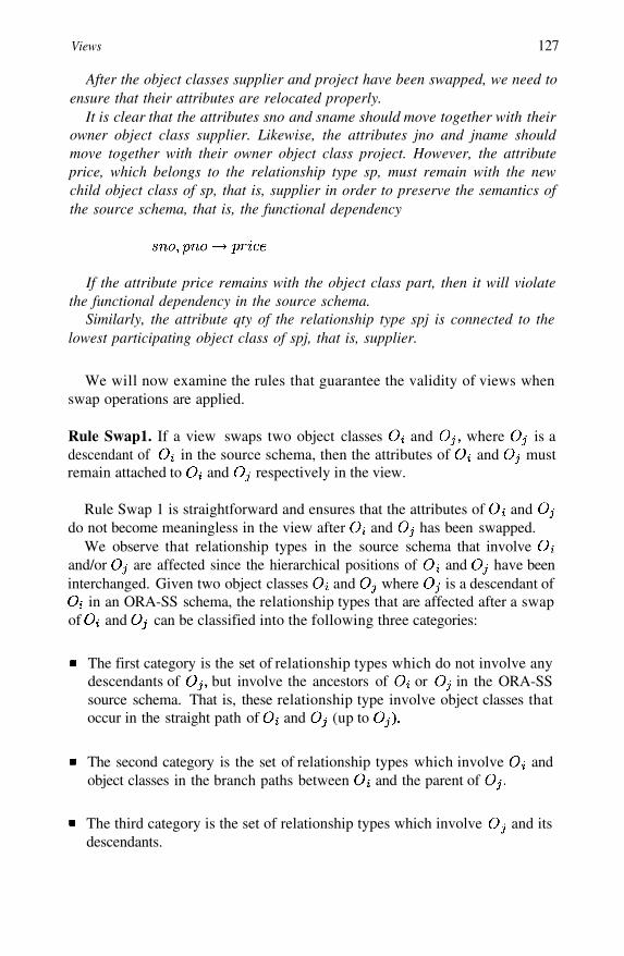
Views 127
After the object classes supplier and project have been swapped, we need toensure that their attributes are relocated properly.
It is clear that the attributes sno and sname should move together with theirowner object class supplier. Likewise, the attributes jno and jname shouldmove together with their owner object class project. However, the attributeprice, which belongs to the relationship type sp, must remain with the newchild object class of sp, that is, supplier in order to preserve the semantics ofthe source schema, that is, the functional dependency
If the attribute price remains with the object class part, then it will violatethe functional dependency in the source schema.
Similarly, the attribute qty of the relationship type spj is connected to thelowest participating object class of spj, that is, supplier.
We will now examine the rules that guarantee the validity of views whenswap operations are applied.
Rule Swap1. If a view swaps two object classes and where is adescendant of in the source schema, then the attributes of and mustremain attached to and respectively in the view.
Rule Swap 1 is straightforward and ensures that the attributes of anddo not become meaningless in the view after and has been swapped.
We observe that relationship types in the source schema that involveand/or are affected since the hierarchical positions of and have beeninterchanged. Given two object classes and where is a descendant of
in an ORA-SS schema, the relationship types that are affected after a swapof and can be classified into the following three categories:
The first category is the set of relationship types which do not involve anydescendants of but involve the ancestors of or in the ORA-SSsource schema. That is, these relationship type involve object classes thatoccur in the straight path of and (up to
The second category is the set of relationship types which involve andobject classes in the branch paths between and the parent of
The third category is the set of relationship types which involve and itsdescendants.

128
These three categories of affected relationship types are handled by the rulesSwap2, Swap3 and Swap4 respectively.
Rule Swap2. Suppose two object classes and in a source schema areswapped during the design of a view. Let S be the set of relationship typeswhich do not involve any descendants of but involve the ancestors ofor in the ORA-SS source schema. For each relationship type R in S, theattributes of R are attached to the lowest participating object class of R in theview.
Rule Swap3 Suppose an object class in a source schema is swapped withits descendant object class during the design of a view. If there exists a re-lationship type which involves at least and where is a descendant ofan object class that lies in the path between and but does not liein the path between and in the ORA-SS source schema, then the subtreerooted at is attached to in the view.
Rule Swap4 Suppose an object class in a source schema is swapped withits descendant object class during the design of a view. For each childof the object class let T be the subtree that is rooted at Let S be the setof relationship types which involve at least and its descendants in T. Ifis the lowest participating object class among the relationship types in S thatlie in the path between and after the swap, then the subtree rooted at
is
Example 6.6 Figure 6.13 shows the relationship types in an ORA-SS sourceschema that will be affected when object classes and are swapped. Therelationship type involves the ancestors of and/or All the objectclasses of any such relationship type will remain in the same path after
and are swapped. However, the lowest participating object class ofmay be changed, and Rule Swap2 will attach any attributes of to the
new lowest participating object class of in the view. In this way, the viewwill not violate the semantics in the source schema and is valid. Note that therelationship type does not involve descendants since the relationshiptype will not be affected by the swap.
The relationship types and in Figure 6.13 involve object classes inthe branch paths of and involves and its child wheredoes not lie in the path between and while involves andwhere lies in the path between and but does not. When and
are swapped, the subtrees rooted at and need to be attached toso that the semantics of and remain intact, and the view obtained afterthe swap is still valid.
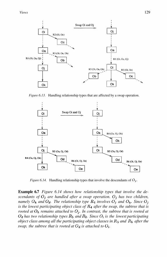
Views 129
Figure 6.13. Handling relationship types that are affected by a swap operation.
Figure 6.14. Handling relationship types that involve the descendants of
Example 6.7 Figure 6.14 shows how relationship types that involve the de-scendants of are handled after a swap operation. has two children,namely and The relationship type involves and Sinceis the lowest participating object class of after the swap, the subtree that isrooted at remains attached to In contrast, the subtree that is rooted at
has two relationship types and Since is the lowest participatingobject class among all the participating object classes in and after theswap, the subtree that is rooted at is attached to
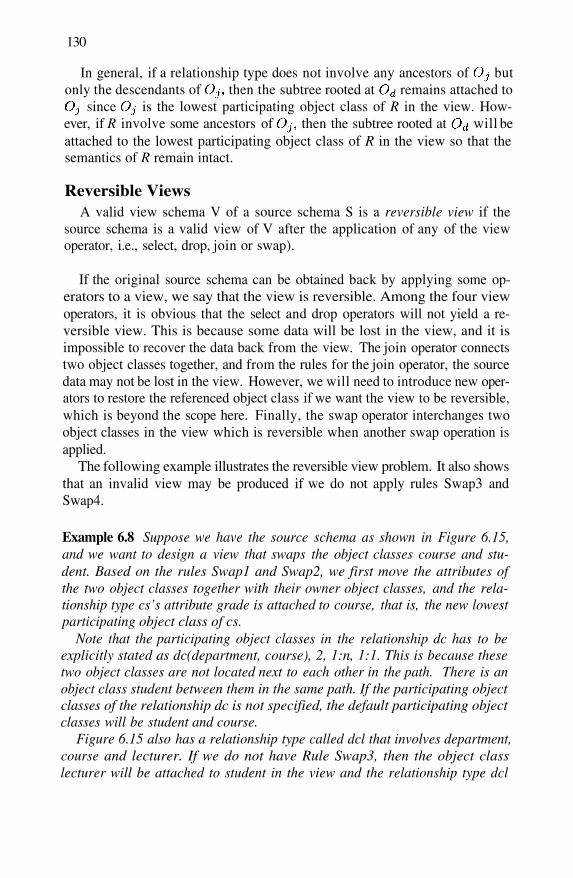
130
In general, if a relationship type does not involve any ancestors of butonly the descendants of then the subtree rooted at remains attached to
since is the lowest participating object class of R in the view. How-ever, if R involve some ancestors of then the subtree rooted at will beattached to the lowest participating object class of R in the view so that thesemantics of R remain intact.
Reversible ViewsA valid view schema V of a source schema S is a reversible view if the
source schema is a valid view of V after the application of any of the viewoperator, i.e., select, drop, join or swap).
If the original source schema can be obtained back by applying some op-erators to a view, we say that the view is reversible. Among the four viewoperators, it is obvious that the select and drop operators will not yield a re-versible view. This is because some data will be lost in the view, and it isimpossible to recover the data back from the view. The join operator connectstwo object classes together, and from the rules for the join operator, the sourcedata may not be lost in the view. However, we will need to introduce new oper-ators to restore the referenced object class if we want the view to be reversible,which is beyond the scope here. Finally, the swap operator interchanges twoobject classes in the view which is reversible when another swap operation isapplied.
The following example illustrates the reversible view problem. It also showsthat an invalid view may be produced if we do not apply rules Swap3 andSwap4.
Example 6.8 Suppose we have the source schema as shown in Figure 6.15,and we want to design a view that swaps the object classes course and stu-dent. Based on the rules Swap1 and Swap2, we first move the attributes ofthe two object classes together with their owner object classes, and the rela-tionship type cs’s attribute grade is attached to course, that is, the new lowestparticipating object class of cs.
Note that the participating object classes in the relationship dc has to beexplicitly stated as dc(department, course), 2, 1:n, 1:1. This is because thesetwo object classes are not located next to each other in the path. There is anobject class student between them in the same path. If the participating objectclasses of the relationship dc is not specified, the default participating objectclasses will be student and course.
Figure 6.15 also has a relationship type called dcl that involves department,course and lecturer. If we do not have Rule Swap3, then the object classlecturer will be attached to student in the view and the relationship type dcl

Views 131
Figure 6.15. ORA-SS schema of course-student-lecturer
Figure 6.16. An invalid view of Figure 6.15 after swapping student and course
will be lost in the view (see Figure 6.16). Thus, all the distinct lecturers willbe repeatedly placed under each student in the corresponding XML view docu-ments. Further, the attribute workload will become meaningless as it wronglybecomes an attribute of lecturer in the view. The view in Figure 6.16 is invalid.
In order to obtain a valid view as shown in Figure 6.17, the object classlecturer needs to move down with course to keep the semantics of the rela-tionship type dcl intact. We also need to explicitly indicate the participatingobject classes of dcl since they are not adjacent to each other in the view. The

132
Figure 6.17. A valid reversible view of Figure 6.15 after swapping student and course
meaning of the attribute workload is still the same as in the source schema,that is, the workload of a lecturer under a given pair of course and department,
Note that we do not need to move the object class tutor up with studentalthough tutor and student are involved in the relationship type cst. This isbecause, based on Rule Swap4, tutor needs to be attached to the lowest par-ticpating object class of cst, i.e., course. Thus, the semantics of the ternaryrelationship type cst remains unchanged and the resulting view in Figure 6.17is valid and reversible.
Let us now apply another swap operator to the view in Figure 6.17 to swapstudent and course. Applying the rules Swap1 and Swap2, the attributes ofstudent and course will move together with their owner object classes. Therelationship attribute grade is thus attached to the object class student again.In addition, the object class lecturer will move up with course as a whole tokeep the semantics of the relationship type dcl intact (Rule Swap4). The viewobtained will be the same as the original source schema in Figure 6.15.
6.6 Design Rules for IDentifier Dependency RelationshipIn the previous sections, we have presented the design rules when drop, join
and swap operations are applied in XML views. However, these rules are notsufficient when the views contain IDD (IDentifier Dependency) relationshiptypes. An IDD relationship type is defined as follows:
Definition 6.1 An object class A is said to be ID dependent on its parent objectclass B if A does not have an identifier, and an A object can be identified by itsparent’s identifier value (say k1) together with some of its own attributes (say
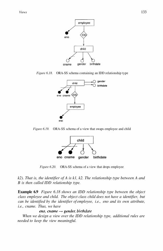
Views 133
Figure 6.18. ORA-SS schema containing an IDD relationship type
Figure 6.19. ORA-SS schema of a view that swaps employee and child
Figure 6.20. ORA-SS schema of a view that drops employee
k2). That is, the identifier of A is k1, k2. The relationship type between A andB is then called IDD relationship type.
Example 6.9 Figure 6.18 shows an IDD relationship type between the objectclass employee and child. The object class child does not have a identifier, butcan be identified by the identifier of employee, i.e., eno and its own attribute,i.e., cname. Thus, we have
When we design a view over the IDD relationship type, additional rules areneeded to keep the view meaningful.
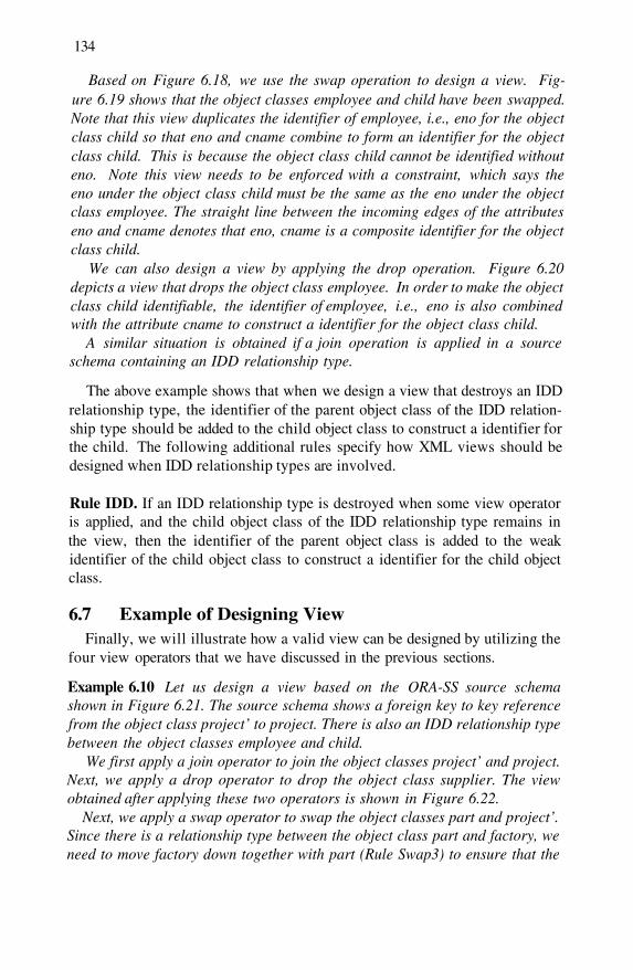
134
Based on Figure 6.18, we use the swap operation to design a view. Fig-ure 6.19 shows that the object classes employee and child have been swapped.Note that this view duplicates the identifier of employee, i.e., eno for the objectclass child so that eno and cname combine to form an identifier for the objectclass child. This is because the object class child cannot be identified withouteno. Note this view needs to be enforced with a constraint, which says theeno under the object class child must be the same as the eno under the objectclass employee. The straight line between the incoming edges of the attributeseno and cname denotes that eno, cname is a composite identifier for the objectclass child.
We can also design a view by applying the drop operation. Figure 6.20depicts a view that drops the object class employee. In order to make the objectclass child identifiable, the identifier of employee, i.e., eno is also combinedwith the attribute cname to construct a identifier for the object class child.
A similar situation is obtained if a join operation is applied in a sourceschema containing an IDD relationship type.
The above example shows that when we design a view that destroys an IDDrelationship type, the identifier of the parent object class of the IDD relation-ship type should be added to the child object class to construct a identifier forthe child. The following additional rules specify how XML views should bedesigned when IDD relationship types are involved.
Rule IDD. If an IDD relationship type is destroyed when some view operatoris applied, and the child object class of the IDD relationship type remains inthe view, then the identifier of the parent object class is added to the weakidentifier of the child object class to construct a identifier for the child objectclass.
6.7 Example of Designing ViewFinally, we will illustrate how a valid view can be designed by utilizing the
four view operators that we have discussed in the previous sections.
Example 6.10 Let us design a view based on the ORA-SS source schemashown in Figure 6.21. The source schema shows a foreign key to key referencefrom the object class project’ to project. There is also an IDD relationship typebetween the object classes employee and child.
We first apply a join operator to join the object classes project’ and project.Next, we apply a drop operator to drop the object class supplier. The viewobtained after applying these two operators is shown in Figure 6.22.
Next, we apply a swap operator to swap the object classes part and project’.Since there is a relationship type between the object class part and factory, weneed to move factory down together with part (Rule Swap3) to ensure that the
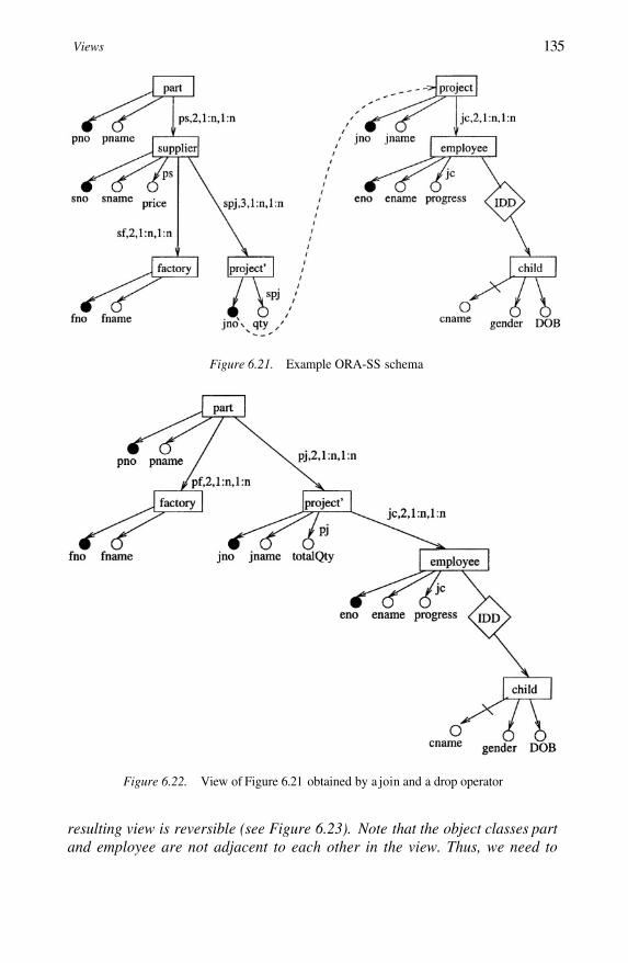
Views 135
Figure 6.21. Example ORA-SS schema
Figure 6.22. View of Figure 6.21 obtained by a join and a drop operator
resulting view is reversible (see Figure 6.23). Note that the object classes partand employee are not adjacent to each other in the view. Thus, we need to
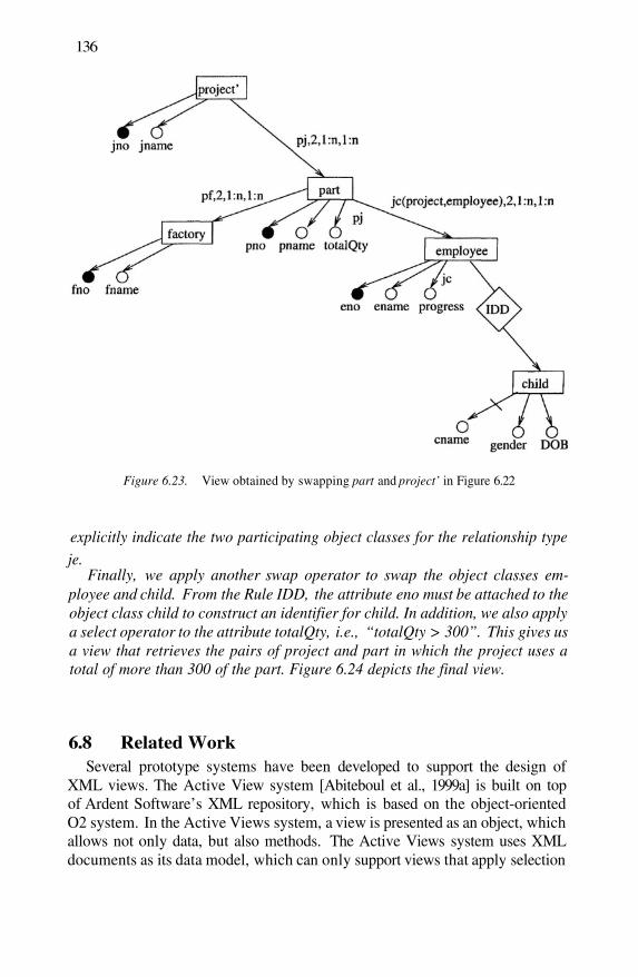
136
Figure 6.23. View obtained by swapping part and project’ in Figure 6.22
explicitly indicate the two participating object classes for the relationship typeje.
Finally, we apply another swap operator to swap the object classes em-ployee and child. From the Rule IDD, the attribute eno must be attached to theobject class child to construct an identifier for child. In addition, we also applya select operator to the attribute totalQty, i.e., “totalQty > 300”. This gives usa view that retrieves the pairs of project and part in which the project uses atotal of more than 300 of the part. Figure 6.24 depicts the final view.
6.8 Related WorkSeveral prototype systems have been developed to support the design of
XML views. The Active View system [Abiteboul et al., 1999a] is built on topof Ardent Software’s XML repository, which is based on the object-orientedO2 system. In the Active Views system, a view is presented as an object, whichallows not only data, but also methods. The Active Views system uses XMLdocuments as its data model, which can only support views that apply selection
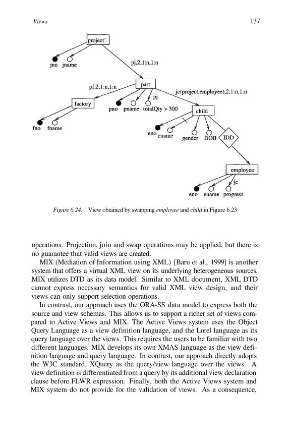
Views 137
Figure 6.24. View obtained by swapping employee and child in Figure 6.23
operations. Projection, join and swap operations may be applied, but there isno guarantee that valid views are created.
MIX (Mediation of Information using XML) [Baru et al., 1999] is anothersystem that offers a virtual XML view on its underlying heterogeneous sources.MIX utilizes DTD as its data model. Similar to XML document, XML DTDcannot express necessary semantics for valid XML view design, and theirviews can only support selection operations.
In contrast, our approach uses the ORA-SS data model to express both thesource and view schemas. This allows us to support a richer set of views com-pared to Active Views and MIX. The Active Views system uses the ObjectQuery Language as a view definition language, and the Lorel language as itsquery language over the views. This requires the users to be familiar with twodifferent languages. MIX develops its own XMAS language as the view defi-nition language and query language. In contrast, our approach directly adoptsthe W3C standard, XQuery as the query/view language over the views. Aview definition is differentiated from a query by its additional view declarationclause before FLWR expression. Finally, both the Active Views system andMIX system do not provide for the validation of views. As a consequence,
138
these two systems cannot guarantee valid XML views that apply projection,join and swap operations.
6.9 SummaryIn this paper, we have proposed a systematic approach for valid XML view
design. The approach is composed of three steps. The first step transforms anXML document into an ORA-SS schema diagram. The second step enrichesthe ORA-SS schema diagram with necessary semantics for valid XML viewsdesign. The final step uses the proposed a set of rules to guide the design ofvalid XML views. We have also presented rules to validate views.
Chapter 7
PHYSICAL DATABASE DESIGN
Until now, we have discussed the importance of designing good conceptualschema for semistructured databases. In practice, physical database design isthe most important step when designing a schema since it affects the perfor-mance of the database system, in particular, the evaluation of queries. [Linget al., 1996] advocates that logical and physical design steps should be inte-grated to guide the design of more “efficient” schemas while maintaining theintegrity of the database.
One important aspect of physical database design is the controlled replica-tion of data to provide more efficient data access. The benefit of replicatingdata is that the speed of queries may improve. The disadvantage is that insert-ing, deleting and maintaining data becomes more difficult, and that extra spaceis required for the storage of the data.
This chapter first reviews the physical database design concepts in the re-lational and hierarchical models. Then we will discuss how to apply relatedconcepts when designing the physical schemas for XML documents.
7.1 Relational Database Physical DesignThe core of relational database theory is functional dependencies and nor-
malization. Normalization is a process that considers the functional depen-dencies between attributes and decides which attributes belong together in arelation. The result is a logical database design that is structurally consistentand has minimal redundancy. However, a normalized database design may notprovide the optimal processing efficiency. This leads to the notion of denor-malization whereby the relational schema is refined by introducing redundancyin a controlled manner to improve the performance of the database system.
Many steps can be taken in the physical design of relational databases.These include adding redundant columns, adding derived columns, collapsing
140
tables, splitting tables both horizontally and vertically. However, the amountof redundancy, if not controlled, will lead to potential inconsistency or updateanomalies. To overcome the problem of update anomalies, [Ling et al., 1996]extended classical functional dependencies (FDs) to include strong FDs.
An FD in a relation R is a strong FD, denoted by if all theattributes in Y will not be updates, or if the update need not be performed inreal-time or online.
For example, the FDs code title and stuNo name are strong FDs.Based on the notion of strong FD, [Ling et al., 1996] defined replicated
3NF, which allows some redundancies in a relation scheme so that the perfor-mance of the database system is improved while ensuring that the integrity ofthe database is not compromised due to various updating anomalies. This isaccomplished by ensuring that
1
2
Only attributes that are rarely updated or attributes that can be updated off-line are duplicated. This is enforced by the definition of the strong FD.
Insertion, deletion, and updating anomalies cannot occur by adhering to astrict updating policy which will validate the updates against the primaryinstance of the attribute.
Definition 7.1 [Ling et al., 1996] Let be a relationaldatabase schema and let be the set of attributes in for Arelation schema is said to be in replicated 3NF if:
1 For each X is not a key of
Case 1: If X is not a role name of the key of then there exists a uniquesuch that X is a key of and is said to
be the primary instance of with respect to the attributes in
Case 2: If X is a role name of the key of and Y is a role name of someattribute in
2 Let X is not a key of and B is non-prime}; the relation schema obtained from after removing all attributesin is in 3NF.
Example 7.1 Consider the following database schema where the keys of therelations are underlined:
Physical Database Design 141
The relation SUPPLY is not in Codd 3NF (in fact, it is not in 2NF) becausewe have sno sname but sname is non-prime and sno is not a candidatekey, and sname is not fully functionally dependent on the key {sno,pno} ofthe SUPPLY relation. However, it is in replicated 3NF by Definition 1 since:
1 we have sno sname and pno pname as we do not or seldom changethe names of suppliers and the names of parts. By Case 1 of Definition 1,SUPPLIER and PART are the primary instances of SUPPLY with respectto the attribute sets {sno, sname} and {pno, pname} respectively; and
2 and the relation schema obtained by removing theattributes sname and pname from SUPPLY is in Codd 3NF.
The replicated normal form provides for inclusion of redundancies in a rela-tion scheme so that the operational efficiency of the database can be enhancedwhile ensuring that the integrity of the database is not compromised due tovarious updating anomalies.
This is achieved by ensuring that only attributes that are rarely updated orattributes that can be updated off-line are duplicated. This is enforced by thedefinition of a strong FD and the second condition of Definition 1.
Therefore, in our example scheme, we need to enforce the following inclu-sion dependencies:
The strong FD and replicated 3NF provides the link between the logicaland physical database design steps by allowing the database designer to makemore informed decisions about how the physical database can be structured (byadding redundant attributes) without compromising the data integrity achievedduring the logical design step while giving better retrieval performance.
7.2 IMS Database Physical DesignPre-relational database systems such as the IBM’s Information Management
System or IMS [Date, 1975] is based on the hierarchical model. A student thattakes a set of courses will be modeled in an IMS hierarchy in which student“parent segments” have subordinate course “child segments” (see Figure 7.1).Such hierarchies are efficient to answer queries such as “Retrieve the coursestaken by some student John”.
However this design leads to redundancy in the course segments. Informa-tion on a course that is taken by many students will be repeated. In order toremove redundant data in the course segments, IMS uses logical parent point-

142
Figure 7.1. Database design using IMS
Figure 7.2. Using logical parent pointers to remove redundancy
ers (see Figure 7.2). Still, they are not suited for queries such as “Retrieve thestudents enrolled in the database course cs2102”.
The main issue here is the lack of symmetry in hierarchies. This becomesproblematic when we need to represent many to many relationships. The IMSdatabase system has built-in functions to provide a symmetric view on the hier-archical structure of data, which reduces unnecessary redundancy and enforcesconsistency of data.
IMS offers physical pairings. Physical pairing involves introducing a newsegment called COURSEGRADE that is a physical child of COURSE and alogical child of STUDENT (see Figure 7.3). The segments COURSEGRADEand STUDENTGRADE are “paired segments” which are declared to the IMSsystem.
Note that physical pairing requires the redundant storage of the intersect-ing data. However, since the segments are paired, when the user inserts an

Physical Database Design 143
Figure 7.3. Physical pairing in IMS
occurrence of either one, IMS will automatically create the corresponding oc-currence of the other.
7.3 Redundancy in ORA-SS Schema DiagramWe now examine the different kinds of data redundancy that can be present
in documents based on XML schemas. Some forms of redundancy are desir-able while other are not.
1 Data redundancy occurs in an instance if there is a many to many relation-ship type, and the participating child object class has attributes.
Consider a schema where the courses that a student is enrolled in are nestedwithin student, as shown in Figure 7.4. Every time an instance of course isrepeated, the values of the attributes of that course are repeated. Althoughthis kind of redundancy is usually described as undesirable, it is not alwaysnecessary to remove this kind of redundancy. The advantage of this redun-dancy is that it can improve the retrieval performance, and it can be retainedif the storage space that the duplicated data takes up is small and if the datathat is replicated is not going to be updated often.
2 Data redundancy occurs if data is replicated to handle symmetric queries.
Consider an XML document that describes the courses that students areenrolled in. There are many ways to organize this data. A schema that issuitable for answering queries about courses that a student is enrolled in,and also queries about students enrolled in a course is shown in Figure 7.5.This schema is suitable for symmetric queries. The relationship types csand sc represent the same real world relationship, namely the relationshipbetween students and courses, but this information is duplicated in the hier-archical storage structure. Duplicating this information is a disadvantage,but it is duplicated only once.
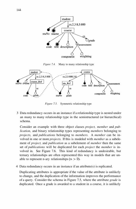
144
Figure 7.4. Many to many relationship type
Figure 7.5. Symmetric relationship type
3 Data redundancy occurs in an instance if a relationship type is nested underan many to many relationship type in the semistructured (or hierarchical)schema.
Consider an example with three object classes project, member and pub-lication, and binary relationship types representing members belonging toprojects, and publications belonging to members. A member can be in-volved in one or more projects. If this is modeled with member as a subele-ment of project, and publication as a subelement of member then the sameset of publications will be duplicated for each project the member is in-volved in. See Figure 7.6. This kind of redundancy is undesirable, butternary relationships are often represented this way in models that are un-able to represent n-ary relationships
4 Data redundancy occurs in an instance if an attribute(s) is replicated.
Duplicating attributes is appropriate if the value of the attribute is unlikelyto change, and the duplication of the information improves the performanceof a query. Consider the schema in Figure 7.5, where the attribute grade isduplicated. Once a grade is awarded to a student in a course, it is unlikely
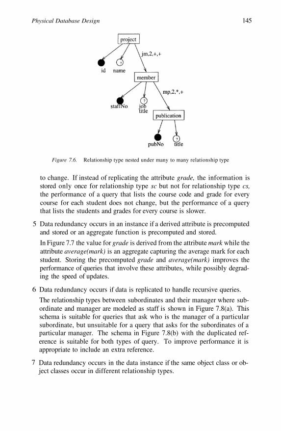
Physical Database Design 145
Figure 7.6. Relationship type nested under many to many relationship type
to change. If instead of replicating the attribute grade, the information isstored only once for relationship type sc but not for relationship type cs,the performance of a query that lists the course code and grade for everycourse for each student does not change, but the performance of a querythat lists the students and grades for every course is slower.
5 Data redundancy occurs in an instance if a derived attribute is precomputedand stored or an aggregate function is precomputed and stored.
In Figure 7.7 the value for grade is derived from the attribute mark while theattribute average(mark) is an aggregate capturing the average mark for eachstudent. Storing the precomputed grade and average(mark) improves theperformance of queries that involve these attributes, while possibly degrad-ing the speed of updates.
6 Data redundancy occurs if data is replicated to handle recursive queries.
The relationship types between subordinates and their manager where sub-ordinate and manager are modeled as staff is shown in Figure 7.8(a). Thisschema is suitable for queries that ask who is the manager of a particularsubordinate, but unsuitable for a query that asks for the subordinates of aparticular manager. The schema in Figure 7.8(b) with the duplicated ref-erence is suitable for both types of query. To improve performance it isappropriate to include an extra reference.
7 Data redundancy occurs in the data instance if the same object class or ob-ject classes occur in different relationship types.
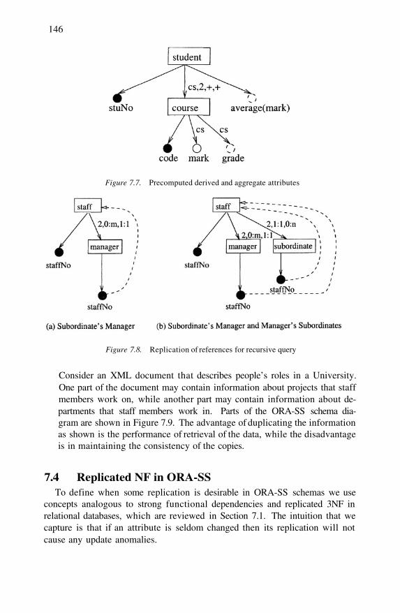
146
Figure 7.7. Precomputed derived and aggregate attributes
Figure 7.8. Replication of references for recursive query
Consider an XML document that describes people’s roles in a University.One part of the document may contain information about projects that staffmembers work on, while another part may contain information about de-partments that staff members work in. Parts of the ORA-SS schema dia-gram are shown in Figure 7.9. The advantage of duplicating the informationas shown is the performance of retrieval of the data, while the disadvantageis in maintaining the consistency of the copies.
7.4 Replicated NF in ORA-SSTo define when some replication is desirable in ORA-SS schemas we use
concepts analogous to strong functional dependencies and replicated 3NF inrelational databases, which are reviewed in Section 7.1. The intuition that wecapture is that if an attribute is seldom changed then its replication will notcause any update anomalies.
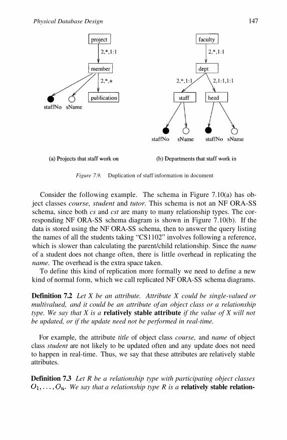
Physical Database Design 147
Figure 7.9. Duplication of staff information in document
Consider the following example. The schema in Figure 7.10(a) has ob-ject classes course, student and tutor. This schema is not an NF ORA-SSschema, since both cs and cst are many to many relationship types. The cor-responding NF ORA-SS schema diagram is shown in Figure 7.10(b). If thedata is stored using the NF ORA-SS schema, then to answer the query listingthe names of all the students taking “CS1102” involves following a reference,which is slower than calculating the parent/child relationship. Since the nameof a student does not change often, there is little overhead in replicating thename. The overhead is the extra space taken.
To define this kind of replication more formally we need to define a newkind of normal form, which we call replicated NF ORA-SS schema diagrams.
Definition 7.2 Let X be an attribute. Attribute X could be single-valued ormultivalued, and it could be an attribute of an object class or a relationshiptype. We say that X is a relatively stable attribute if the value of X will notbe updated, or if the update need not be performed in real-time.
For example, the attribute title of object class course, and name of objectclass student are not likely to be updated often and any update does not needto happen in real-time. Thus, we say that these attributes are relatively stableattributes.
Definition 7.3 Let R be a relationship type with participating object classesWe say that a relationship type R is a relatively stable relation-

148
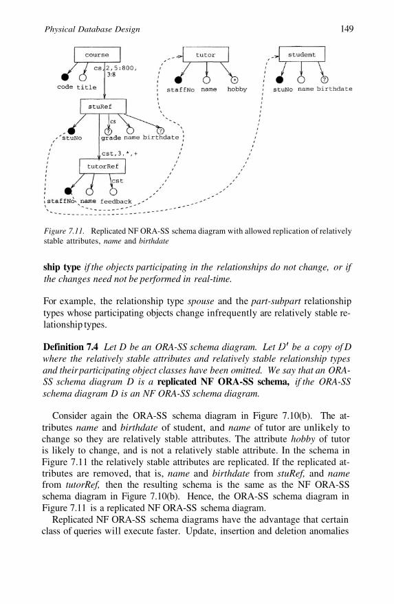
Physical Database Design 149
Figure 7.11. Replicated NF ORA-SS schema diagram with allowed replication of relativelystable attributes, name and birthdate
ship type if the objects participating in the relationships do not change, or ifthe changes need not be performed in real-time.
For example, the relationship type spouse and the part-subpart relationshiptypes whose participating objects change infrequently are relatively stable re-lationship types.
Definition 7.4 Let D be an ORA-SS schema diagram. Let be a copy of Dwhere the relatively stable attributes and relatively stable relationship typesand their participating object classes have been omitted. We say that an ORA-SS schema diagram D is a replicated NF ORA-SS schema, if the ORA-SSschema diagram D is an NF ORA-SS schema diagram.
Consider again the ORA-SS schema diagram in Figure 7.10(b). The at-tributes name and birthdate of student, and name of tutor are unlikely tochange so they are relatively stable attributes. The attribute hobby of tutoris likely to change, and is not a relatively stable attribute. In the schema inFigure 7.11 the relatively stable attributes are replicated. If the replicated at-tributes are removed, that is, name and birthdate from stuRef, and namefrom tutorRef, then the resulting schema is the same as the NF ORA-SSschema diagram in Figure 7.10(b). Hence, the ORA-SS schema diagram inFigure 7.11 is a replicated NF ORA-SS schema diagram.
Replicated NF ORA-SS schema diagrams have the advantage that certainclass of queries will execute faster. Update, insertion and deletion anomalies
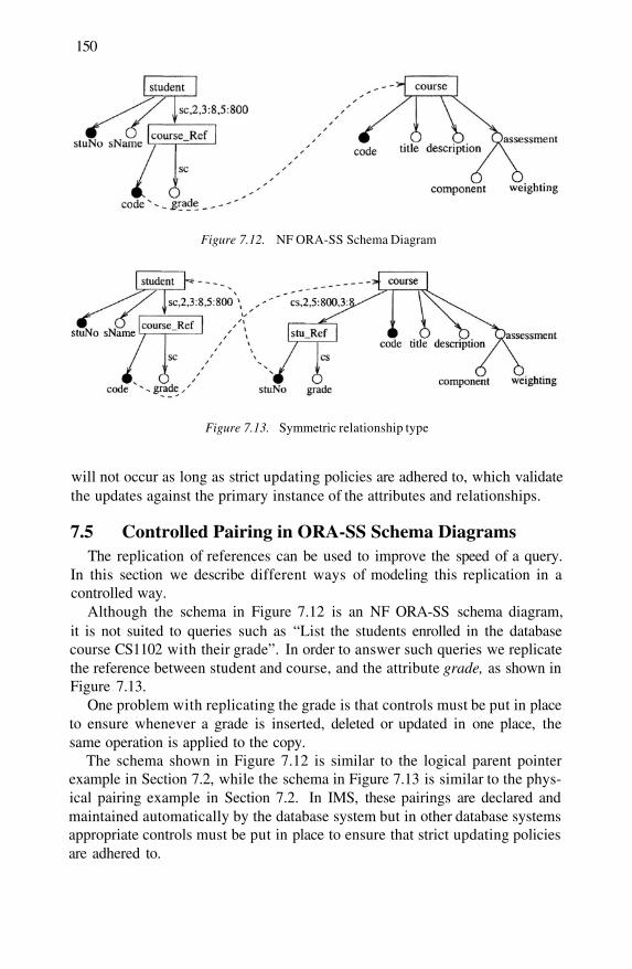
150
Figure 7.12. NF ORA-SS Schema Diagram
Figure 7.13. Symmetric relationship type
will not occur as long as strict updating policies are adhered to, which validatethe updates against the primary instance of the attributes and relationships.
7.5 Controlled Pairing in ORA-SS Schema DiagramsThe replication of references can be used to improve the speed of a query.
In this section we describe different ways of modeling this replication in acontrolled way.
Although the schema in Figure 7.12 is an NF ORA-SS schema diagram,it is not suited to queries such as “List the students enrolled in the databasecourse CS1102 with their grade”. In order to answer such queries we replicatethe reference between student and course, and the attribute grade, as shown inFigure 7.13.
One problem with replicating the grade is that controls must be put in placeto ensure whenever a grade is inserted, deleted or updated in one place, thesame operation is applied to the copy.
The schema shown in Figure 7.12 is similar to the logical parent pointerexample in Section 7.2, while the schema in Figure 7.13 is similar to the phys-ical pairing example in Section 7.2. In IMS, these pairings are declared andmaintained automatically by the database system but in other database systemsappropriate controls must be put in place to ensure that strict updating policiesare adhered to.
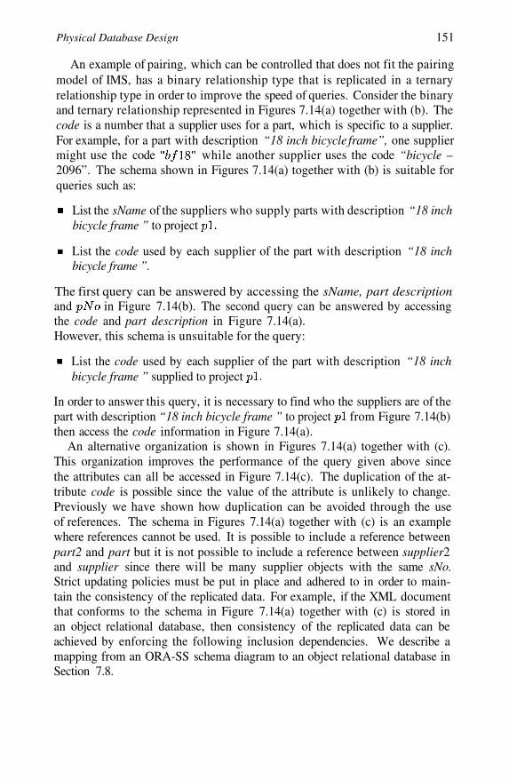
Physical Database Design 151
An example of pairing, which can be controlled that does not fit the pairingmodel of IMS, has a binary relationship type that is replicated in a ternaryrelationship type in order to improve the speed of queries. Consider the binaryand ternary relationship represented in Figures 7.14(a) together with (b). Thecode is a number that a supplier uses for a part, which is specific to a supplier.For example, for a part with description “18 inch bicycle frame”, one suppliermight use the code while another supplier uses the code “bicycle –2096”. The schema shown in Figures 7.14(a) together with (b) is suitable forqueries such as:
List the sName of the suppliers who supply parts with description “18 inchbicycle frame ” to project
List the code used by each supplier of the part with description “18 inchbicycle frame ”.
The first query can be answered by accessing the sName, part descriptionand in Figure 7.14(b). The second query can be answered by accessingthe code and part description in Figure 7.14(a).However, this schema is unsuitable for the query:
List the code used by each supplier of the part with description “18 inchbicycle frame ” supplied to project
In order to answer this query, it is necessary to find who the suppliers are of thepart with description “18 inch bicycle frame ” to project from Figure 7.14(b)then access the code information in Figure 7.14(a).
An alternative organization is shown in Figures 7.14(a) together with (c).This organization improves the performance of the query given above sincethe attributes can all be accessed in Figure 7.14(c). The duplication of the at-tribute code is possible since the value of the attribute is unlikely to change.Previously we have shown how duplication can be avoided through the useof references. The schema in Figures 7.14(a) together with (c) is an examplewhere references cannot be used. It is possible to include a reference betweenpart2 and part but it is not possible to include a reference between supplier2and supplier since there will be many supplier objects with the same sNo.Strict updating policies must be put in place and adhered to in order to main-tain the consistency of the replicated data. For example, if the XML documentthat conforms to the schema in Figure 7.14(a) together with (c) is stored inan object relational database, then consistency of the replicated data can beachieved by enforcing the following inclusion dependencies. We describe amapping from an ORA-SS schema diagram to an object relational database inSection 7.8.
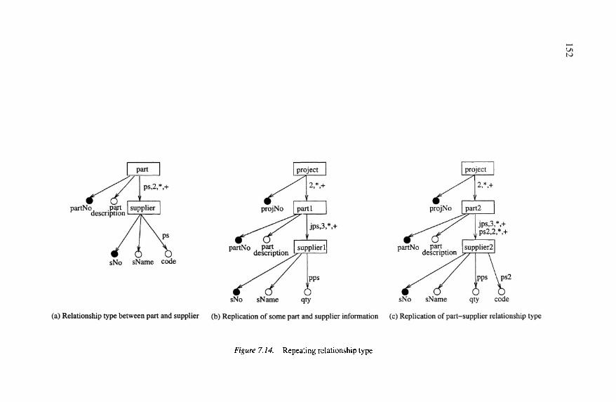
152

Physical Database Design 153
7.6 Measure of Data ReplicationAs with relational databases, a normalized XML schema design may not
provide optimal efficiency. The example below demonstrates how the ORA-SS data model can be used to estimate the cost of replicating data.
Consider the ORA-SS schema diagram in Figure 7.15 that shows the objectclasses student and course. A student can take 3 to 8 courses and a coursecan have 5 to 800 students. A course has a code, title, description, and assess-ment. The assessment is a multivalued composite attribute that comprises ofcomponent and its weighting. For example, the practical component can havea weighting of 20%, the test component can have a weighting of 10%, and theexam component can have a weighting of 70%.
Let us assume that
number of students = 20000
number of courses = 500
length of code = 10 bytes
length of title = 50 bytes
length of description = 1000 bytes
length of component = 20 bytes
length of weighting = 4 bytes
length of grade = 2 bytes
length of reference = 10 bytes
The length of each assessment is given by the length of component andweighting = 20 + 4 bytes = 24 bytes. Since we have 3 types of assessment,namely, practical, test, and exam, this attribute occupies a total of 72 bytes.With these information, we can estimate the storage and update cost of model-ing data in a particular way.
Let us consider the storage requirements for the course elements. In theschema in Figure 7.15(a), each course is repeated for each student taking thecourse, which means that the details of each course is stored a minimum of5 times and a maximum of 800 times (based on the participation constraint
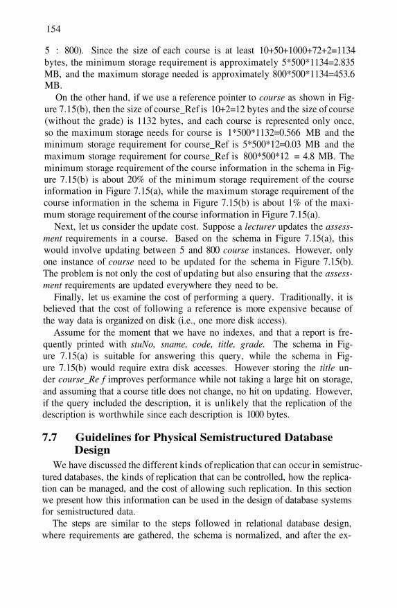
154
5 : 800). Since the size of each course is at least 10+50+1000+72+2=1134bytes, the minimum storage requirement is approximately 5*500*1134=2.835MB, and the maximum storage needed is approximately 800*500*1134=453.6MB.
On the other hand, if we use a reference pointer to course as shown in Fig-ure 7.15(b), then the size of course_Ref is 10+2=12 bytes and the size of course(without the grade) is 1132 bytes, and each course is represented only once,so the maximum storage needs for course is 1*500*1132=0.566 MB and theminimum storage requirement for course_Ref is 5*500*12=0.03 MB and themaximum storage requirement for course_Ref is 800*500*12 = 4.8 MB. Theminimum storage requirement of the course information in the schema in Fig-ure 7.15(b) is about 20% of the minimum storage requirement of the courseinformation in Figure 7.15(a), while the maximum storage requirement of thecourse information in the schema in Figure 7.15(b) is about 1% of the maxi-mum storage requirement of the course information in Figure 7.15(a).
Next, let us consider the update cost. Suppose a lecturer updates the assess-ment requirements in a course. Based on the schema in Figure 7.15(a), thiswould involve updating between 5 and 800 course instances. However, onlyone instance of course need to be updated for the schema in Figure 7.15(b).The problem is not only the cost of updating but also ensuring that the assess-ment requirements are updated everywhere they need to be.
Finally, let us examine the cost of performing a query. Traditionally, it isbelieved that the cost of following a reference is more expensive because ofthe way data is organized on disk (i.e., one more disk access).
Assume for the moment that we have no indexes, and that a report is fre-quently printed with stuNo, sname, code, title, grade. The schema in Fig-ure 7.15(a) is suitable for answering this query, while the schema in Fig-ure 7.15(b) would require extra disk accesses. However storing the title un-der course_Re f improves performance while not taking a large hit on storage,and assuming that a course title does not change, no hit on updating. However,if the query included the description, it is unlikely that the replication of thedescription is worthwhile since each description is 1000 bytes.
7.7 Guidelines for Physical Semistructured DatabaseDesign
We have discussed the different kinds of replication that can occur in semistruc-tured databases, the kinds of replication that can be controlled, how the replica-tion can be managed, and the cost of allowing such replication. In this sectionwe present how this information can be used in the design of database systemsfor semistructured data.
The steps are similar to the steps followed in relational database design,where requirements are gathered, the schema is normalized, and after the ex-
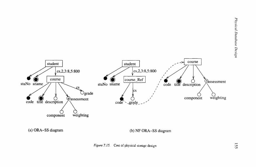
Physical D
atabase Design
155
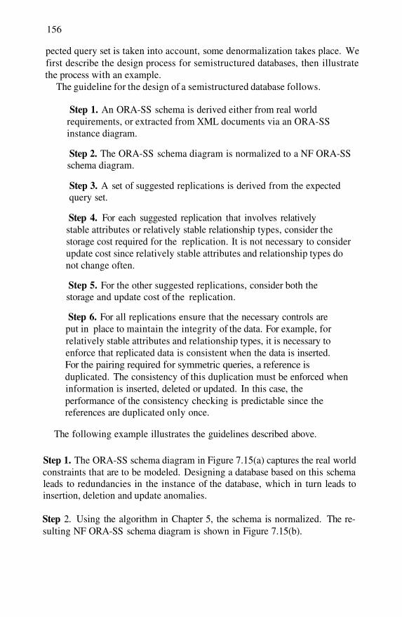
156
pected query set is taken into account, some denormalization takes place. Wefirst describe the design process for semistructured databases, then illustratethe process with an example.
The guideline for the design of a semistructured database follows.
Step 1. An ORA-SS schema is derived either from real worldrequirements, or extracted from XML documents via an ORA-SSinstance diagram.
Step 2. The ORA-SS schema diagram is normalized to a NF ORA-SSschema diagram.
Step 3. A set of suggested replications is derived from the expectedquery set.
Step 4. For each suggested replication that involves relativelystable attributes or relatively stable relationship types, consider thestorage cost required for the replication. It is not necessary to considerupdate cost since relatively stable attributes and relationship types donot change often.
Step 5. For the other suggested replications, consider both thestorage and update cost of the replication.
Step 6. For all replications ensure that the necessary controls areput in place to maintain the integrity of the data. For example, forrelatively stable attributes and relationship types, it is necessary toenforce that replicated data is consistent when the data is inserted.For the pairing required for symmetric queries, a reference isduplicated. The consistency of this duplication must be enforced wheninformation is inserted, deleted or updated. In this case, theperformance of the consistency checking is predictable since thereferences are duplicated only once.
The following example illustrates the guidelines described above.
Step 1. The ORA-SS schema diagram in Figure 7.15(a) captures the real worldconstraints that are to be modeled. Designing a database based on this schemaleads to redundancies in the instance of the database, which in turn leads toinsertion, deletion and update anomalies.
Step 2. Using the algorithm in Chapter 5, the schema is normalized. The re-sulting NF ORA-SS schema diagram is shown in Figure 7.15(b).
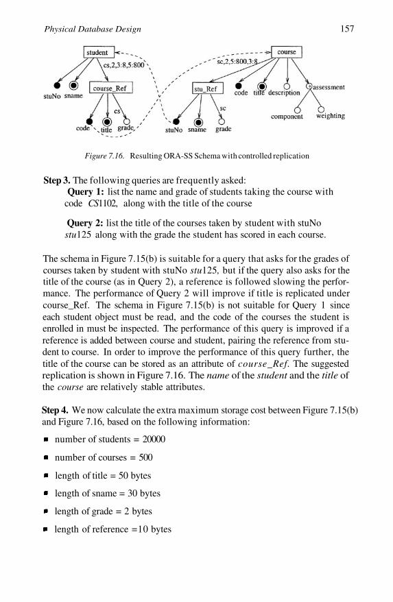
Physical Database Design 157
Figure 7.16. Resulting ORA-SS Schema with controlled replication
Step 3. The following queries are frequently asked:Query 1: list the name and grade of students taking the course with
code CS1102, along with the title of the course
Query 2: list the title of the courses taken by student with stuNostu125 along with the grade the student has scored in each course.
The schema in Figure 7.15(b) is suitable for a query that asks for the grades ofcourses taken by student with stuNo stu125, but if the query also asks for thetitle of the course (as in Query 2), a reference is followed slowing the perfor-mance. The performance of Query 2 will improve if title is replicated undercourse_Ref. The schema in Figure 7.15(b) is not suitable for Query 1 sinceeach student object must be read, and the code of the courses the student isenrolled in must be inspected. The performance of this query is improved if areference is added between course and student, pairing the reference from stu-dent to course. In order to improve the performance of this query further, thetitle of the course can be stored as an attribute of course_Ref. The suggestedreplication is shown in Figure 7.16. The name of the student and the title ofthe course are relatively stable attributes.
Step 4. We now calculate the extra maximum storage cost between Figure 7.15(b)and Figure 7.16, based on the following information:
number of students = 20000
number of courses = 500
length of title = 50 bytes
length of sname = 30 bytes
length of grade = 2 bytes
length of reference =10 bytes
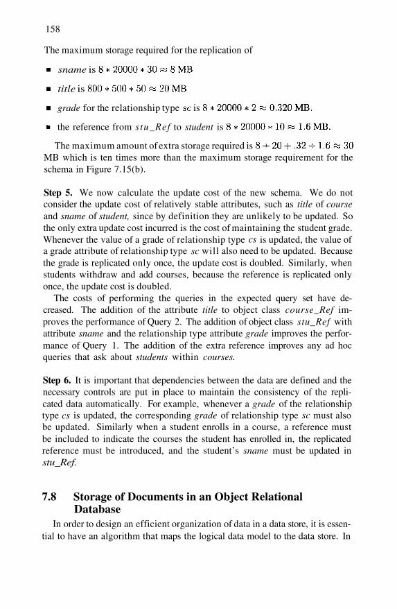
158
The maximum storage required for the replication of
sname is
title is
grade for the relationship type is
the reference from s tu_Ref to student is
The maximum amount of extra storage required isMB which is ten times more than the maximum storage requirement for theschema in Figure 7.15(b).
Step 5. We now calculate the update cost of the new schema. We do notconsider the update cost of relatively stable attributes, such as title of courseand sname of student, since by definition they are unlikely to be updated. Sothe only extra update cost incurred is the cost of maintaining the student grade.Whenever the value of a grade of relationship type is updated, the value ofa grade attribute of relationship type will also need to be updated. Becausethe grade is replicated only once, the update cost is doubled. Similarly, whenstudents withdraw and add courses, because the reference is replicated onlyonce, the update cost is doubled.
The costs of performing the queries in the expected query set have de-creased. The addition of the attribute title to object class course_Ref im-proves the performance of Query 2. The addition of object class stu_Ref withattribute sname and the relationship type attribute grade improves the perfor-mance of Query 1. The addition of the extra reference improves any ad hocqueries that ask about students within courses.
Step 6. It is important that dependencies between the data are defined and thenecessary controls are put in place to maintain the consistency of the repli-cated data automatically. For example, whenever a grade of the relationshiptype is updated, the corresponding grade of relationship type must alsobe updated. Similarly when a student enrolls in a course, a reference mustbe included to indicate the courses the student has enrolled in, the replicatedreference must be introduced, and the student’s sname must be updated instu_Ref.
7.8 Storage of Documents in an Object RelationalDatabase
In order to design an efficient organization of data in a data store, it is essen-tial to have an algorithm that maps the logical data model to the data store. In
cs
cs
sc
sc
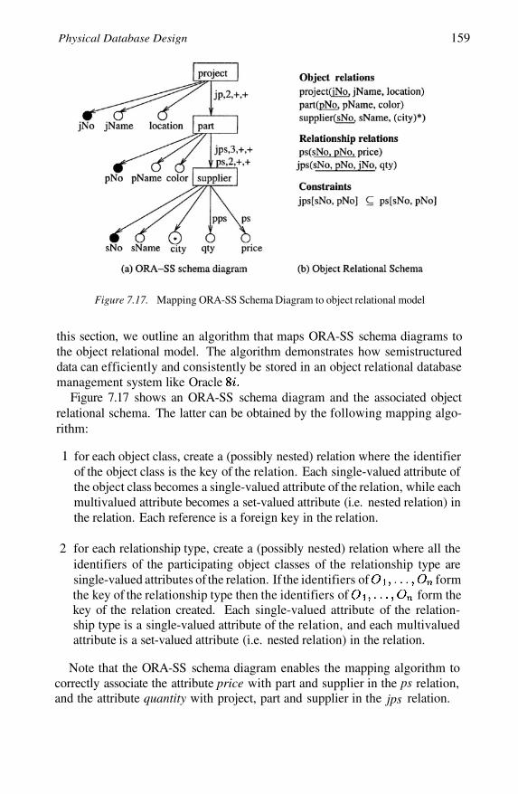
Physical Database Design 159
Figure 7.17. Mapping ORA-SS Schema Diagram to object relational model
this section, we outline an algorithm that maps ORA-SS schema diagrams tothe object relational model. The algorithm demonstrates how semistructureddata can efficiently and consistently be stored in an object relational databasemanagement system like Oracle
Figure 7.17 shows an ORA-SS schema diagram and the associated objectrelational schema. The latter can be obtained by the following mapping algo-rithm:
1 for each object class, create a (possibly nested) relation where the identifierof the object class is the key of the relation. Each single-valued attribute ofthe object class becomes a single-valued attribute of the relation, while eachmultivalued attribute becomes a set-valued attribute (i.e. nested relation) inthe relation. Each reference is a foreign key in the relation.
2 for each relationship type, create a (possibly nested) relation where all theidentifiers of the participating object classes of the relationship type aresingle-valued attributes of the relation. If the identifiers of formthe key of the relationship type then the identifiers of form thekey of the relation created. Each single-valued attribute of the relation-ship type is a single-valued attribute of the relation, and each multivaluedattribute is a set-valued attribute (i.e. nested relation) in the relation.
Note that the ORA-SS schema diagram enables the mapping algorithm tocorrectly associate the attribute price with part and supplier in the relation,and the attribute quantity with project, part and supplier in the relation.
psjps
160
7.9 SummaryWhile the process of transforming an ORA-SS schema diagram to an NF
ORA-SS schema diagram can lead to databases that have no replicated datawhich in turn leads to a reduction in anomalies, the addition of references mayadversely degrade the performance of queries on the database.
In this chapter, we have addressed how replication can be added back into aschema in a controlled manner in order to improve the performance of queriesthat are frequently asked. We have reviewed how attributes that seldom changeare dealt with in relational databases, and how pairings are maintained auto-matically in hierarchical IMS databases for answering symmetric queries effi-ciently.
We have described the kinds of replication that can arise in semistructureddatabases, and how the replication of relatively stable attributes and relation-ship types can be added, and how pairings between object classes can be main-tained. These concepts have roots in the approaches taken by relational andIMS databases to deal with replication and answering symmetric queries re-spectively. The costs incurred in the replication of data in semistructureddatabases include the storage cost, the update cost and the performance cost.Recognizing that some attributes and relationship types are relatively stablegives a more realistic picture of the update cost.
Guidelines for semistructured database design are introduced and demon-strated, from requirements gathering, through conceptual modeling to physicalmodeling. Finally, we have outlined an algorithm for storing XML documentsefficiently and consistently in a traditional database system.

Chapter 8
CONCLUSION
Web applications typically deal with data that is semistructured. With theincreased number of web applications, and the increasing amount of data thatis produced and consumed by these applications, there is a need for processesthat are guaranteed to maintain the consistency of the data. One such processis the design of a data repository that manages semistructured data.
The steps in the design of a repository for semistructured data are as follows:
1 Choose a data model that is able to represent the semantics necessary formodeling semistructured data,
2 Capture the semantics of the data that will be stored, either by:
(a) extracting the schema from a set of documents and discovering the se-mantics in a data model, or
(b) studying the constraints in the real world and capturing them in a datamodel,
3
4
5
Reorganize the schema into an NF ORA-SS schema diagram to avoid repli-cation of data in the XML documents,
Consider the typical query set and reorganize the schema to improve theperformance of typical queries, perhaps by introducing controlled replica-tion of data,
Consider the users of the system and define views over the data for individ-ual users or groups of users.
These steps are outlined in Figure 8.1, and the chapters in the book thatcorrespond to the steps are highlighted with each step.

162
Figure 8.1. Steps in the Design of Repositories for Semistructured Data
Because of the rich semantics that can be represented in the ORA-SS datamodel, it can be used as the foundation for other work in the semistructureddata field. We list some further possibilities here:
We have discussed how the ORA-SS data model can be used to recognizeif there is redundancy in a semistructured data repository. Hence, furthernormal forms for semistructured data and the underlying theory could bedefined based on the ORA-SS data model. The ORA-SS instance diagramcan also be used to capture how the instance of the data needs to changeafter the schema has been restructured.
We have shown how semistructured data and XML data can be mapped tothe object relational data model. More work needs to be done to designefficient storage organizations for other data models (such as the objectoriented and relational data models) with indexes based on the ORA-SSschema.

Conclusion 163
The ORA-SS data model can be used to identify which views are mean-ingful. This work can be extended to define how materialized views areupdated, what updates to views are valid, and how updates to views arepropagated to the underlying data.
Query optimization involves rewriting queries into a form that will executefaster than the original query. Semantic query optimization involves rewrit-ing the query based on the semantics of the data to improve query perfor-mance. The ORA-SS schema diagram can provide the necessary semantics,and could be used for semantic query optimization in semi structured datarepositories.
The ORA-SS data model provides a user-friendly way to visualize the in-stance and schema of a semistructured data store, and can be used in toolsthat require data visualization. Preliminary work in this area is presentedin [Ni and Ling, 2003].
The ORA-SS data model provides a simple and standard way for represent-ing semantics which can be used for data integration. A large part of dataintegration involves finding equivalences or matches between two or moreschema. The problem of finding equivalences of object classes, relation-ship types and attributes between diagrams is very complex. It is easier tofind equivalences automatically or semi-automatically with a good under-standing of the underlying semantics of the data.

This page intentionally left blank
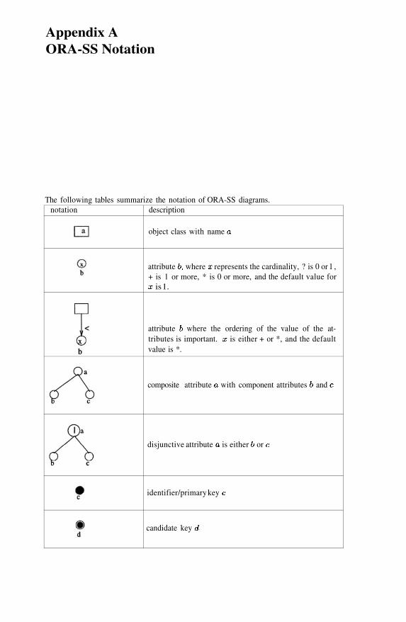
Appendix AORA-SS Notation
The following tables summarize the notation of ORA-SS diagrams.notation description
object class with name
attribute where represents the cardinality, ? is 0 or 1 ,+ is 1 or more, * is 0 or more, and the default value for
is 1.
attribute where the ordering of the value of the at-tributes is important. is either + or *, and the defaultvalue is *.
composite attribute with component attributes and
disjunctive attribute is either or
identifier/primary key
candidate key
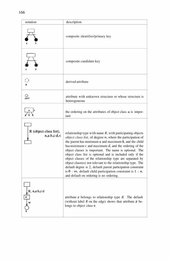
166
notation description
composite identifier/primary key
composite candidate key
derived attribute
attribute with unknown structure or whose structure isheterogeneous
the ordering on the attributes of object class is impor-tant
relationship type with name R, with participating objectsobject class list, of degree where the participation ofthe parent has minimum and maximum and the childhas minimum and maximum and the ordering of theobject classes is important. The name is optional. Theobject class list is optional and is included only if theobject classes of the relationship type are separated byobject class(es) not relevant to the relationship type. Thedefault degree is 2, default parent participation constraintis default child participation constraint isand default on ordering is no ordering.
attribute belongs to relationship type R. The default(without label R on the edge) shows that attribute be-longs to object class
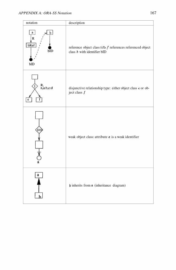
APPENDIX A: ORA-SS Notation 167
notation description
reference object class references referenced objectclass with identifier bID
disjunctive relationship type: either object class or ob-ject class
weak object class: attribute is a weak identifier
inherits from (inheritance diagram)

This page intentionally left blank
References
Abiteboul, S. (1999). On views and XML. In Proceedings of 18th ACM Symposium on Princi-ples of Database Systems.
Abiteboul, S., Amann, B., Cluet, S., Eyal, A., Mignet, L., and Milo, T. (1999a). Active views forelectronic commerce. In Proceedings of 25th International Conference on Very Large DataBases.
Abiteboul, S., Buneman, P., and Suciu, D. (1999b). Data On the Web-From Relational to Semistruc-tured Data and XML. Morgan Kaufman Publishers, San Francisco, California.
Apparao, V. and Byrne, S. (1 October 1998). Document object model (DOM) level 1 specifica-tion. W3C Recommendation.
Arenas, M. and Libkin, L. (2004). A normal form for XML documents. ACM Trans. DatabaseSyst., 29(1):195–232.
Baru, C. K., Gupta, A., Ludascher, B., Marciano, R., Papakonstantinou, Y., Velikhov, P., andChu, V. (1999). XML-based information mediation with MIX. In SIGMOD 1999, Proceed-ings ACM SIGMOD International Conference on Management of Data.
Bray, T., Paoli, J., and Sperberg-McQueen, C. M. (Oct. 2000). Extensible markup language(XML) 1.0. 2nd edition. http://www.w3.org/TR/REC-xml.
Buneman, P., Davidson, S., Fan, W., Hara, C., and Tan, W.C. (2001a). Keys for XML. In Pro-ceedings of the Tenth International World Wide Web Conference.
Buneman, P., Davidson, S., Fan, W., Hara, C., and Tan, W.C. (2001b). Reasoning about keys forXML. In International Workshop on Database Programming Languages.
Carey, M. J., Kiernan, J., Shanmugasundaram, J., Shekita, E. J., and Subramanian, S. N. (2000).Xperanto: Middleware for publishing object-relational data as XML documents. In Proceed-ings of 26th International Conference on Very Large Data Bases, pages 646–648.
Chen, Y.B., Ling, T.W., and Lee, M.L. (2002). Designing valid XML views. In Proceedings of21st International Conference on Conceptual Modeling.
Christophides, V., Cluet, S., and (2000). On wrapping query languages and efficientXML integration. In Proceedings of the 2000 ACM SIGMOD International Conference onManagement of Data, pages 141–152.
Cluet, S., Veltri, P., and Vodislav, D. (2001). Views in a large scale XML repository. In Proceed-ings of 27th International Conference on Very Large Data Bases, pages 271–280.
Date, C. J. (1975). An Introduction to Database Systems. Addison Wesley, 1st edition.Deutsch, A., Fernandez, M., and Suciu, D. (1999). Storing semistructured data with STORED.
In ACM SIGMOD, pages 431–442.
170
Deutsch, A. and Tannen, V. (2003). Mars: A system for publishing xml from mixed and redun-dant storag e. In VLDB.
Dobbie, G., Wu, X., Ling, T.W., and Lee, M.L. (2000). ORA-SS: An object-relationship-attributemodel for semi-structured data. Technical Report TR21/00, School of Computing, NationalUniversity of Singapore.
Embley, D.W. and Mok, W.Y. (2001). Developing XML documents with guaranteed “good”properties. In Proc. of 20th International Conference on Conceptual Modeling.
Fan, W. and (2000). Integrity Constraints for XML. In Proceedings of the NineteenthACM SIGMOD-SIGACT-S1GART Symposium on Principles of Database Systems, Dallas,Texas, USA, pages 23–34. ACM.
Fernandez, M., Tan, W., and Suciu, D. (2000). SilkRoute: Trading between relations and XML.In Proceedings of the 9th International World Wide Web Conference.
Florescu, D. and Kossmann, D. (1999). Storing and querying XML data using an RDBMS.IEEE Data Engineering Bulletin, 22(3):27–34.
Goldman, R. and Widom, J. (1997). Dataguides: Enabling query formulation and optimizationin semistructured databases. In Proc. of 23rd International Conference on Very Large DataBases, pages 436–445.
ISO/IEC (2000). Information technology - text and office systems - regular language descriptionfor XML (RELAX) - part 1: RELAX core. DTR 22250-1.
Lee, D. and Chu, W. (2000). Constraints-preserving transformation from XML document typedefinition to relational schema. In Proc. 19th International Conference on Conceptual Mod-eling, pages 323–338.
Lee, S.Y., Lee, M.L., Ling, T.W., and Kalinichenko, L.A. (1999). Designing good semi-structureddatabases. In Proc. 18th International Conference on Conceptual Modeling, pages 131–145.
Ling, T. W. (1989). A normal form for sets of not-necessarily normalized relations. In Proceed-ings of the 22nd Hawaii International Conference on System Sciences, pages 578–586. IEEEComputer Society Press.
Ling, T. W. and Yan, L. L. (1994). NF-NR: A practical normal form for nested relations. Journalof Systems Integration, 4:309–340.
Ling, T.W. (1985). A normal form for entity-relationship diagrams. In Proc. 4th InternationalConference on Entity-Relationship Approach.
Ling, T.W., Goh, C.H., and Lee, M.L. (1996). Extending classical functional dependencies forphysical database design. Information and Software Technology, 38:601–608.
Ling, T.W. and Teo, P.K. (1993). Inheritance conflicts in object-oriented systems. In Proc. 4thInternational Conference on Database and Expert Systems Applications, DEXA ’93, pages189–200.
Mani, M., Lee, D., and Muntz, R.R. (2001). Semantic data modeling using XML schemas. InProc. of 20th International Conference on Conceptual Modeling, pages 149–163.
Manolescu, I., Florescu, D., and Kossmann, D. (2001). Answering XML queries on heteroge-neous data sources. In Proceedings of 27th International Conference on Very Large DataBases, pages 241–250.
McHugh, J., Abiteboul, S., Goldman, R., Quass, D., and Widom, J. (1997). Lore: A databasemanagement system for semistructured data. SIGMOD Record, 26(3):54–66.
Mo, Y. and Ling, T.W. (2002). Storing and maintaining semistructured data efficiently in anobject-relational database. In Proc. of 3rd International Conference on Web InformationSystems Engineering (WISE 2002), pages 247–256.
Ni, W. and Ling, T.W. (2003). GLASS: A graphical query language for semi-structured data. InProc. of Eighth International Conference on Database Systems for Advanced Applications(DASFAA ’03).
REFERENCES 171
Ozsoyoglu, Z.M. and Yuan, L.Y. (1987). A new normal form for nested relations. ACM Trans-action on Database Systems, 12(1).
Shanmugasundaram, J., Tufte, K., Zhang, C., He, G., DeWitt, D.J., and Naughton, J.F. (1999).Relational databases for querying XML documents: Limitations and opportunities. In Proc.of 25th International Conference on Very Large Data Bases, pages 79–90.
Suciu, D. (1998). Semistructured data and XML. In Proc, of 5th International Conference onFoundations of Data Organization.
Thompson, H.S., Beech, D., Maloney, M., and (Eds), N. Mendelson (May 2001). XML SchemaPart 1: Structures. http://www.w3.org/TR/xmlscheina-l.
Wang, Q.Y., Xu, J.X., and Wong, K.F. (2000). Approximate graph schema extraction for semistruc-tured data. In Proc. of 7th International Conference on Extending Database Technology.
Widom, J. (1999). Data management for XML: Research directions. IEEE Data EngineeringBulletin, 22(3):44–52.
Wu, X., Ling, T.W., Lee, M.L., and Dobbie, G. (2001a). Designing semistructured databasesusing ORA-SS model. In Proc. of 2nd International Conference on Web Information SystemsEngineering.
Wu, X.Y., Ling, T.W., Lee, S.Y., Lee, M.L., and Dobbie, G. (November 2001b). NF-SS: Anormal form for semistructured schemata. In Proceedings of the International Workshop onData Semantics in Web Information Systems (DASWIS/ER2001). Springer-Verlag.

This page intentionally left blank

Index
ANY, 44Active View, 5, 111, 136Aggregate, 145Agora, 5Attribute of object class, 43Attribute of relationship type, 44Attribute, 43–45Binary relationship type, 38–39CM Hypergraph, 3, 18–19, 21, 35Candidate identifier, 44Composite attribute, 44, 60, 64, 85Composite candidate identifier, 44Composite identifier, 44DOM, 3, 12, 14,34DTD, 4, 8–12,34Data model, 3Data path expression, 74Data redundancy, 143–146DataGuide, 3, 15–16, 59,74Default value, 44Denormalization, 139Dependent object class, 43, 88Derived attribute, 44, 145Disjunction, 49Drop, 116–120,132Element set, 8Element, 7Entity Relationship, 21, 79Extended Entity Relationship, 4, 21–24, 35Extended functional dependency, 82Extraction Rules, 60Fixed value, 44Fourth normal form, 79Functional dependency diagram, 52–55IDREF, 61,64, 70IMS, 47, 141–143Identifier dependency relationship type, 43,88
132, 134Identifier, 44–45, 61, 64Inheritance diagram, 55–56
Instance diagram, 49, 51Integration, 2Invalid view, 114Join, 116, 121, 124–125, 132Key, 107Level of nested relation, 83Logical pointer, 142MIX, 5, 111, 137Many to many relationship type, 143Multivalued attribute, 60, 64, 85NF ORA–SS schema diagram, 88–91NF-NR, 80, 84–85NF-SS, 4, 109NNF, 80Nested relational model, 80Normalization, 4, 77, 80O-NF, 85, 87OEM, 3, 13, 15–16ORA-SS, 4, 12,28, 32,35Object class list, 38Object class, 37–38, 64, 85, 88Object relational model, 158Object, 60Ordering, 48Participation constraint, 38, 66Physical design, 5Physical pairing, 142–143Project, 117R-NF,86–88RELAXNG, 4, 9Recursive query, 145Redundancy, 77References, 46–47Relational database, 139Relationship type, 38–39, 41–43, 65, 86, 88Relationship, 8Relatively stable attribute, 147, 154Relatively stable relationship type, 147, 154Replicated 3NF, 140–141
174
Replicated NF ORA-SS schema, 149Reversible view, 130S3-NF,4, 108S3-graph, 3, 16–18,29–31,34Schema diagram, 37–39, 41–43, 45–49Schema extraction, 4, 59, 62Select, 116, 132SilkRoute, 5, 111Simple attribute, 60Single-valued attribute, 60, 64, 85Strong functional dependency, 140Subelement, 61, 63Swap, 116, 125, 127–128, 130, 132Symmetric query, 141, 143Ternary relationship type, 38–39, 66Text segment, 63
Third normal form, 79Update anomaly, 140Valid view, 111Views, 5Weak identifier, 43Weak key, 107XML Schema, 4, 8XML Tree, 4, 24–28, 35XML element, 60XML, 2, 62XNF, 4, 109–110XPERANTO, 5,111Xyleme, 5,111YAT, 5
About the Authors
Dr Gillian DOBBIE is currently an Associate Professor in the Departmentof Computer Science at the University of Auckland, New Zealand, and DeputyDirector of the Software Engineering Programme.[See http://www.cs.auckland.ac.nz/people/profile.php?id=gdob002]
She received a Ph.D. from the University of Melbourne, an M.Tech.(Hons)and B.Tech.(Hons) in Computer Science from Massey University. She haslectured at Massey University, the University of Melbourne, and Victoria Uni-versity of Wellington, and held visiting research positions at Griffith Universityand the National University of Singapore.
Her research interests include formal foundations for databases, object ori-ented databases, semistructured databases, logic and databases, data warehous-ing, data mining, access control, e-commerce and data modeling. She has pub-lished 27 international refereed journal and conference papers. Some of thepublications are listed in http://www.informatik.uni- trier.de/ ley/db/indices/a-tree/d/Dobbie:Gillian.html.
She is programme co-chair on ADC05 and ADC06, and has served as pro-gramme co-chair on WEBH2001 and WEBH2002. She has served on pro-gramme committees for many international conferences including DOOD97,ADC98, DaWaK01, WISE2002, and ACE2003, and has refereed papers forinternational journals such as TPLP and VLDB.
176
Dr. Mong Li LEE is currently an Assistant Professor in the School of Com-puting at the National University of Singapore. She received her Ph.D. de-gree in Computer Science from the National University of Singapore in 1999.Her thesis examines translation, integration and update issues in a federateddatabase environment. She was awarded the IEEE Singapore InformationTechnology Gold Medal for being the top student in the Computer Scienceprogram in 1989.
Mong Li joined the Department of Computer Science, National Universityof Singapore, as a Senior Tutor from 1989 to 1999. In 1999, she was appointedFellow in the School of Computing and lectured Introduction to Programmingin JAVA, a Lecture-on-Demand module. She was a Visiting Fellow at the Com-puter Science Department, University of Wisconsin-Madison and Consultantat QUIQ Incorporated, USA, from September 1999 to August 2000.
Her research interests include the cleaning and integration of heterogeneousand semistructured data, performance database issues in dynamic environ-ments, and medical informatics. Her work has been published in ACM SIG-MOD, ACM SIGKDD, VLDB, ICDE and ER conferences. She is a co-Editorfor the Proceedings of the 17th International Conference on Conceptual Model-ing (ER 1998) and Proceedings of VLDB 2002 Workshop EEXTT and CAiSE2002 Workshop DIWeb (LNCS #2590, Springer-Verlag). She is a ProgramCommittee member of VLDB (2002, 2003, 2004), DASFAA (2003, 2004) andER (1998, 1999, 2001, 2003, 2004) and a reviewer for IEEE TKDE and DAMIjournals.

ABOUT AUTHORS 177
Dr. Tok Wang LING is a Professor of the Department of Computer Science,School of Computing at the National University of Singapore, Singapore. Hewas the Head of Information Technology Division, Deputy Head of the De-partment of Information Systems and Computer Science, and a Vice Dean ofthe School. Before joining the University as a lecturer in 1979, he was a sci-entific staff at Bell Northern Research, Ottawa, Canada. He received his Ph.D.and M.Math., both in Computer Science, from Waterloo University, Canada,and B.Sc.(1 Hons) in Mathematics from Nanyang University, Singapore.
His research interests include Data Modeling, Entity-Relationship Approach,Object-Oriented Data Model, Normalization Theory, Logic and Database, In-tegrity Constraint Checking, Semistructured Data Model, and Data Warehous-ing. He has published more than 150 international journal/conference papersand chapters in books, mainly in data modeling. He also co-edited 12 confer-ence and workshop proceedings.
He organized and served as program committee co-chair of DASFAA’95,DOOD’95, ER’98, WISE 2002, and ER 2003. He organized and served/servesas conference co-chair of Human.Society @Internet conference in 2001 and2003, WAIM 2004, ER 2004, and DASFAA 2005. He served/serves as work-shop co-chair of DOOD’95 Post-Conference Workshops, the 8th InternationalParallel Computing Workshop, and the International Workshop on ConceptualModel-directed Web Information Integration and Mining held in conjunctionwith ER 2004.
He serves/served on the program committees of more than 100 internationaldatabase conferences since 1985. He is currently the chair of the steering com-mittee of International Conference on Database Systems for Advanced Appli-cations (DASFAA), a member of the steering committee of International Con-ference on Conceptual Modeling (ER) and the International Conference onHuman.Society@Internet. He was chair and vice chair of the steering commit-tee of ER conference and a member of the steering committee of InternationalConference on Deductive and Object-Oriented Databases (DOOD).
He is an editor of the journal Data & Knowledge Engineering, InternationalJournal of Cooperative Information Systems, Journal of Database Manage-ment, Journal of Data Semantics, and World Wide Web: Internet and WebInformation Systems. He is also an advisor of the ACM Transactions on In-ternet Technology. He is a member of ACM, IEEE, and Singapore ComputerSociety.