senso r/actuato r boxes -...
TRANSCRIPT
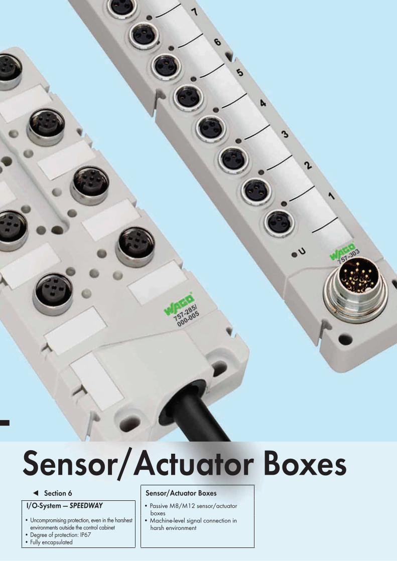
Sensor/Actuator Boxes !!!Section 6 Sensor/Actuator Boxes
I/O-System — SPEEDWAY • Passive M8/M12 sensor/actuator boxes• Machine-level signal connection in harsh environment
• Uncompromising protection, even in the harshest environments outside the control cabinet
• Degree of protection: IP67• Fully encapsulated
579
10
10
Page
General Product Information 580
Item Number Keys 581
Standards and Rated Conditions 582
Interfaces and Configurations 583
Description Item No.
M12 Sensor/Actuator Box, with Connection Cable
4-way, 4 pin, 5 m connecting cable 757-244/000-005 584
4-way, 4 pin, 10 m connecting cable 757-244/000-010
6-way, 4 pin, 5 m connecting cable 757-264/000-005
6-way, 4 pin, 10 m connecting cable 757-264/000-010
8-way, 4 pin, 5 m connecting cable 757-284/000-005
8-way, 4 pin, 10 m connecting cable 757-284/000-010
8-way, 4 pin, 25 m connecting cable 757-284/000-025
4-way, 5 pin, 5 m connecting cable 757-245/000-005 586
4-way, 5 pin, 10 m connecting cable 757-245/000-010
6-way, 5 pin, 5 m connecting cable 757-265/000-005
6-way, 5 pin, 10 m connecting cable 757-265/000-010
8-way, 5 pin, 5 m connecting cable 757-285/000-005
8-way, 5 pin, 10 m connecting cable 757-285/000-010
8-way, 5 pin, 25 m connecting cable 757-285/000-025
M12 Sensor/Actuator Box, with M23 Connector
4-way, 4-pole, M23 connector 757-144 588
6-way, 4-pole, M23 connector 757-164
8-way, 4-pole, M23 connector 757-184
4-way, 5-pole, M23 connector 757-145 590
6-way, 5-pole, M23 connector 757-165
8-way, 5-pole, M23 connector 757-185
8-way, 5-pole, without LED, M23 connector 757-185/100-000
M8 Sensor/Actuator Box, with Connection Cable
4-way, 3 pin, 2 m connecting cable 757-443/000-002 592
4-way, 3 pin, 5 m connecting cable 757-443/000-005
4-way, 3 pin, 10 m connecting cable 757-443/000-010
6-way, 3 pin, 5 m connecting cable 757-463/000-005
6-way, 3 pin, 10 m connecting cable 757-463/000-010
8-way, 3 pin, 5 m connecting cable 757-483/000-005
8-way, 3 pin, 10 m connecting cable 757-483/000-010
10-way, 3 pin, 5 m connecting cable 757-403/000-005
10-way, 3 pin, 10 m connecting cable 757-403/000-010
M8 Sensor/Actuator Box, with M16 Connector
4-way, 3-pole, M16 connector 757-343 594
6-way, 3-pole, M16 connector 757-363
8-way, 3-pole, M16 connector 757-383
10-way, 3-pole, M16 connector 757-303
Accessories
Labeling cards, adapter, connecting cable 596
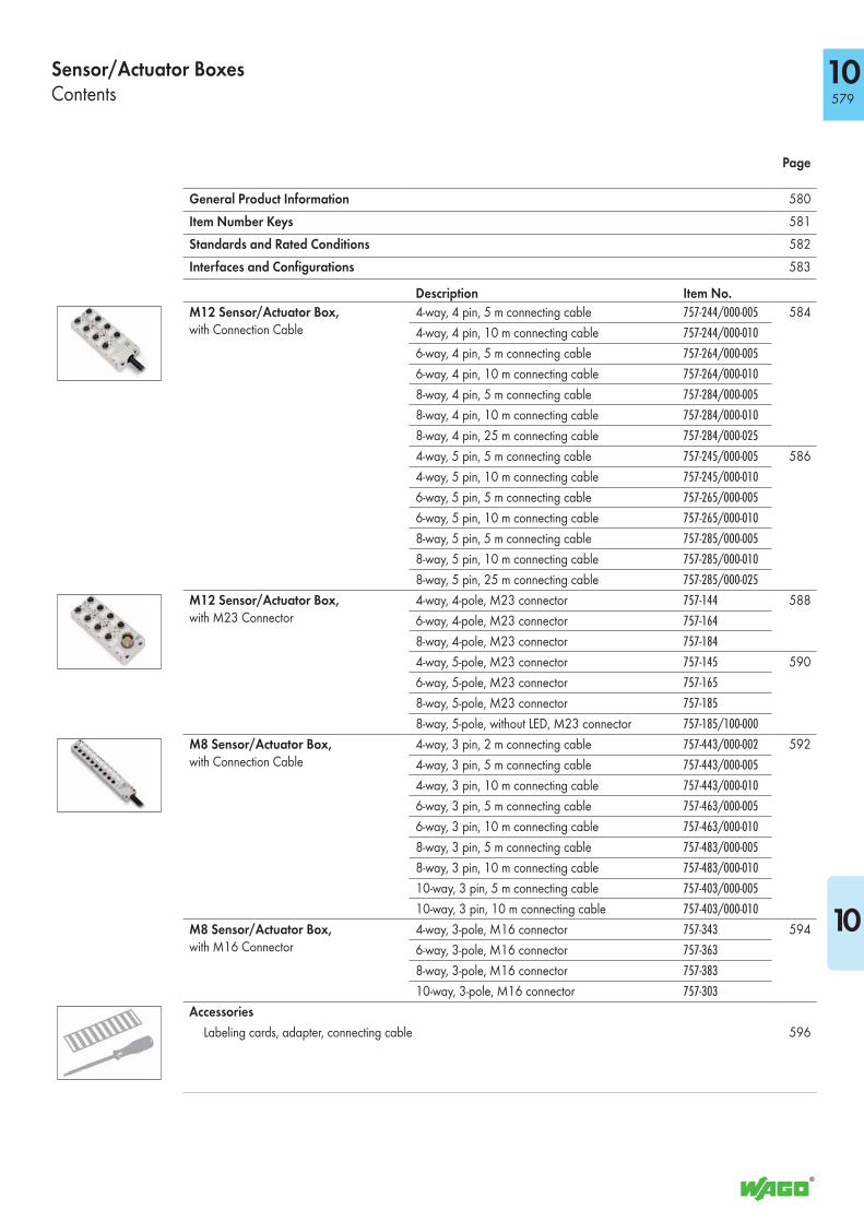
Sensor/Actuator BoxesContents

10580
For Signal Acquisition at the Machine LevelPassive M8/M12 sensor/actuator boxes are placed close to the process and ac-quire signals at the machine level. They can be used in very harsh environmental conditions and establish the connection from sensors and actuators to the control-ler across molded or detachable cables. Use of standardized pluggable connectors supports sensor and actuator plug & play, and the individual wiring of I/O signals to automation components in the control cabi-net is simplified via trunk cable. Cabling is well-arranged and minimized.
Extreme Mechanical PerformanceA system/machine is exposed to severe mecha-nical and thermal influences. It is important to process its signals despite strong vibration and shock. The sensor/actuator boxes are used at the machine level. Full encapsulation safeguards system operation, mitigating the effects of extreme vibration and temperature loads when collecting signals and supplying power via the connecting cable of the controller or other automation com-ponents in the uncritically positioned area of the control cabinet.
Flexible Assembly The sensor/actuator boxes can be directly moun-ted on the machine. Extensive engineering en-sures compliance with standardized specifications from CNOMO guidelines regarding the spacing of assembly drill holes that are often used in passive distributor or sensor/actuator boxes. An optional adapter is available that can be used to seamlessly mount two modules side by side. This has the advantage of maintaining a defined distance for proper routing of the sensor/actuator cables and of avoiding contamination points.
Signal Acquisition in Exceptionally Harsh
Conditions
The sensor/actuator boxes are very robust and
comply with degree of protection IP67 or IP68 with
molded cabling (72 hours at 1 m water depth).
Therefore, they are the ideal solution for applications
where signals must be recorded under extreme
environmental conditions (temperature, shock,
vibration) without a control cabinet. They’re also
excellent alternatives when the use of an active IP67
I/O system would not be cost-effective due to a
low signal count or simple signal conditions (digital
signal acquisition/output).
Plug & play Connection Technology
The sensor/actuator boxes with a removable con-
necting cable (M16 or M23 pluggable connector)
are well-suited to areas where frequent easy release
and reconnection is required (transport, modifica-
tion, service, etc.).
Fixed Trunk Cable
The sensor/actuator boxes with molded cables are
preferred when challenging cable paths do not
allow the use of preassembled M16/M23 cables.
Sensor/Actuator BoxesGeneral Product Information
● Simple and economical addition to
IP20 automation products
- With increased requirements for environmental conditions
- For plug & play connection technology when needed
- For simpler cable installation in the form of trunk cables
● High-quality PUR connecting cables (suitable for drag chains, halogen free)
● Fully encapsulated (resistance and leak-proof)
● Flange sockets (metal design)
● -25 °C to +80 °C operating temperature range
● Incl. status LEDs

581
10
10
Sensor/Actuator BoxesItem Number Keys
Standards and Rated Conditions
Item No. : 757-abc/x00-0yy
Series
a: Design 1: M12 Sensor/Actuator Box with M23 Connector 2: M12 Sensor/Actuator Box with Cable Connection 3: M8 Sensor/Actuator Box with M16 Connector 4: M8 Sensor/Actuator Box with Cable Connection
b: No of M8/M12 connectors 4: 4 ea. 6: 6 ea. 8: 8 ea. 0: 10 ea.
c: Pole No. 3: 3-pole 4: 4-pole 5: 5-pole
Explanation of the components for the item number key
x00: Status LEDs 100: Without status LEDs
0yy: Length of the connecting cable 002: 2m 005: 5m 010: 10m 025: 25m
General Specifications
Electrical Data
Contact resistance 10 mΩ
Operating voltage 10 V ... 30 VDC
Current carrying capacity 2 A per signal; 9 A per SA box (M12) or 6 A per SA box (M8)
Switching function PNP
Mechanical Data
Protection type
Sensor/actuator boxes with cable connection IP68 (72 hours at 1 m water depth)
Sensor/actuator boxes with M16/M23 connector
IP67
Operating temperature -25 °C … +80 °C
Mounting Screw mount
Mounting position any
Vibration resistance 5g acc. to IEC 60068-2-6
Shock resistance 49g acc. to IEC 60068-2-27
Material Data
General Silicon and halogen free
Encapsulation Fully encapsulated with conformal coating (UL 94 V0)
Housing material PA 66 (UL 94 V0); RAL 7035
Connecting cable Suitable for drag chains

10582
B
D
F
b)
a)
1)
3)
4)
2)
b)
a)
1)
3)
4)
2)
A
C
E
b)
a)
1)
3)
4)
2)
b)
a)
1)
3)
4)
2)
(1) Sensor/actuator marking(2) Module marking(3) LED status indicator (by channel), yellow (4) LED operating indicator module, green
Housing design (A)M12 Sensor/Actuator Box with Cable Connection• Sensor/actuator connections M12 (a)• Connecting cable (b)
Housing design (B)M8 Sensor/Actuator Box with Cable Connection• Sensor/actuator connections M8 (a)• Connecting cable (b)
Housing design (C)M12 Sensor/Actuator Box with M23 Connector
• Sensor/actuator connections M12 (a)• Supply input M23 (b)
Housing design (D)M8 Sensor/Actuator Box with M16 Connector
• Sensor/actuator connections M8 (a)• Supply input M16 (b)
Adapter (E)• Optional accessory• For seamless assembly of two side-by-side
sensor/actuator boxes• Defined distance for proper cable connection• Covers contamination points• W x H x L (mm):
10-way: 20 x 16 x 175 8-way: 20 x 16 x 152 6-way: 20 x 16 x 123 4-way: 20 x 16 x 117
Degree of protection (F)• All modules are fully encapsulated• Protection class: IP67/68• Printing on back of module details
pin assignment
Sensor/Actuator BoxesInterfaces and Configurations

583
10
<_18_><__ 20__>
<_18_><__ 26 ___>
<___26___><__22__>
<_____34_____><__22__>
10
Sensor/Actuator BoxesInterfaces and Configurations
Dimensions and Mounting Dimensions of M12 Sensor/Actuator Boxes
The dimensions also apply to M12 sensor/actuator boxes with cable connection.
Dimensions and Mounting Dimensions of M8 Sensor/Actuator Boxes
The dimensions also apply to M8 sensor/actuator boxes with cable connection.
Dimensions:Depth of M12 sensor/actuator boxes or M8 sensor/actuator boxes
Dimensions in mm
(4-way)
(6-way)
(8-way)
Dimensions in mm
(4-way)
(6-way)
(8-way)
(10-way)
(4-way)
(6-way)
(8-way)
(10-way)
10584
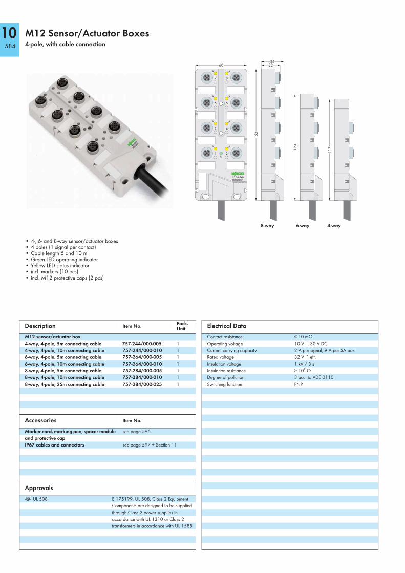
M12 Sensor/Actuator Boxes4-pole, with cable connection
8-way 6-way 4-way
<___26___><___________ 60 ___________> <__22__>
<___________________________ 1
23
___________________________>
<_________________________1
17
_________________________>
<____________________________________1
52
____________________________________>
• 4-, 6- and 8-way sensor/actuator boxes• 4 poles (1 signal per contact)• Cable length 5 and 10 m• Green LED operating indicator• Yellow LED status indicator• incl. markers (10 pcs)• incl. M12 protective caps (2 pcs)
Description Item No.Pack. Unit
M12 sensor/actuator box
4-way, 4-pole, 5m connecting cable 757-244/000-005 1
4-way, 4-pole, 10m connecting cable 757-244/000-010 1
6-way, 4-pole, 5m connecting cable 757-264/000-005 1
6-way, 4-pole, 10m connecting cable 757-264/000-010 1
8-way, 4-pole, 5m connecting cable 757-284/000-005 1
8-way, 4-pole, 10m connecting cable 757-284/000-010 1
8-way, 4-pole, 25m connecting cable 757-284/000-025 1
Accessories Item No.
Marker card, marking pen, spacer module
and protective cap
see page 596
IP67 cables and connectors see page 597 + Section 11
Approvals
r UL 508 E 175199, UL 508, Class 2 Equipment
Components are designed to be supplied
through Class 2 power supplies in
accordance with UL 1310 or Class 2
transformers in accordance with UL 1585
Electrical Data
Contact resistance ≤ 10 mΩ
Operating voltage 10 V ... 30 V DC
Current carrying capacity 2 A per signal; 9 A per SA box
Rated voltage 32 V ~ eff.
Insulation voltage 1 kV / 3 s
Insulation resistance > 109 Ω
Degree of pollution 3 acc. to VDE 0110
Switching function PNP

10585
10
–
1 2 3 4
+
5 6 7 8
4 3 5
1
4 5
1
4 3 5
1
4 3 5
1
4 3 5
1
4 3 5
1
4 3 5
1
4 3 5
1
Color of conductors
Socket
4-way 6-way 8-waygreen/yellow
brown
blue
white
green
yellow
grey
pink
red
black
violet
gr. yel. yel. yel. yel. yel. yel. yel. yel.
Mechanical Data
Degree of protection IP68 (1 meter water depth for 72 hours)
acc. to EN 60529 In fully locked position
with the appropriate plugs or protective
caps
Operating temperature -25 °C ... +80 °C (current load according
to derating curve)
Fixing Screw mounting
Dimensions (mm) W x H x L 4-way: 60 x 26 x 117
6-way: 60 x 26 x 123
8-way: 60 x 26 x 152
Weight 4-way: 165 g
6-way: 180 g
8-way: 215 g
without cable
Mounting position any
Vibration resistance acc. to IEC 60068-2-6
Shock resistance acc. to IEC 60068-2-27
Material Data
General Silicon and halogen free
Potting Fully encapsulated with conformal coating
(UL 94 V0)
Enclosure PA 66 (UL 94 V0); RAL 7035
Contacts
I/O slot Socket, M12 x 1, 4-pole incl. PE
Contact CuSn, pre-nickeled and 0.8 µm gold-plated
Tapped bush Zn diecast nickel-plated
Seal Viton
Connection cycles 50
Connecting cable
Cable design Outer sheath PUR halogen-free
Black
Cable end 100 mm stripped
Cable Ø 7.5 mm SA box 4-way
7.8 mm SA box 6-way
8.2 mm SA box 8-way
Conductor design n x 0.34 mm2 + 3 x 1.00 mm2
conductor 0.34 mm2
extra-fine stranded 43 x 0.1 mm
conductor 1.00 mm2
extra-fine stranded 55 x 0.15 mm
color identification of conductors
Suitable for drag chain applications
bending radius min. 10 x cable Ø
amb. temperature range -40°C ... +90°C stagnant;
-5°C ... +80°C moving
10586
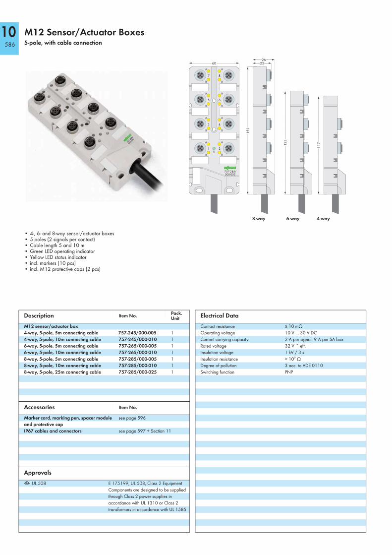
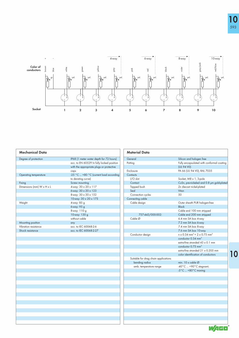
M12 Sensor/Actuator Boxes5-pole, with cable connection
8-way 6-way 4-way
<___26___><___________ 60 ___________> <__22__>
<___________________________ 1
23
___________________________>
<_________________________1
17
_________________________>
<____________________________________1
52
____________________________________>
• 4-, 6- and 8-way sensor/actuator boxes• 5 poles (2 signals per contact)• Cable length 5 and 10 m• Green LED operating indicator• Yellow LED status indicator• incl. markers (10 pcs)• incl. M12 protective caps (2 pcs)
Description Item No.Pack. Unit
M12 sensor/actuator box
4-way, 5-pole, 5m connecting cable 757-245/000-005 1
4-way, 5-pole, 10m connecting cable 757-245/000-010 1
6-way, 5-pole, 5m connecting cable 757-265/000-005 1
6-way, 5-pole, 10m connecting cable 757-265/000-010 1
8-way, 5-pole, 5m connecting cable 757-285/000-005 1
8-way, 5-pole, 10m connecting cable 757-285/000-010 1
8-way, 5-pole, 25m connecting cable 757-285/000-025 1
Accessories Item No.
Marker card, marking pen, spacer module
and protective cap
see page 596
IP67 cables and connectors see page 597 + Section 11
Approvals
r UL 508 E 175199, UL 508, Class 2 Equipment
Components are designed to be supplied
through Class 2 power supplies in
accordance with UL 1310 or Class 2
transformers in accordance with UL 1585
Electrical Data
Contact resistance ≤ 10 mΩ
Operating voltage 10 V ... 30 V DC
Current carrying capacity 2 A per signal; 9 A per SA box
Rated voltage 32 V ~ eff.
Insulation voltage 1 kV / 3 s
Insulation resistance > 109 Ω
Degree of pollution 3 acc. to VDE 0110
Switching function PNP

10587
10
1 2 3 4 5 6 7 8
2 435
1
2 435
1
2 435
1
2 435
1
2 435
1
2 435
1
2 435
1
2 435
1
Color of conductors
Socket
4-way 6-way 8-waygreen/yellow
brown
bllue
white
green
yellow
grey
pink
red
black
violet
gr. yel. yel. yel. yel. yel. yel. yel. yel.grey/pink
red/blue
white/green
brown/green
white/yellow
yellow/brown
white/grey
grey/brown
yel.
+ -
Mechanical Data
Degree of protection IP68 (1 meter water depth for 72 hours)
acc. to EN 60529 In fully locked position
with the appropriate plugs or protective
caps
Operating temperature -25 °C ... +80 °C (current load according
to derating curve)
Fixing Screw mounting
Dimensions (mm) W x H x L 4-way: 60 x 26 x 117
6-way: 60 x 26 x 123
8-way: 60 x 26 x 152
Weight 4-way: 165 g
6-way: 185 g
8-way: 225 g
without cable
Mounting position any
Vibration resistance acc. to IEC 60068-2-6
Shock resistance acc. to IEC 60068-2-27
Material Data
General Silicon and halogen free
Potting Fully encapsulated with conformal coating
(UL 94 V0)
Enclosure PA 66 (UL 94 V0); RAL 7035
Contacts
I/O slot Socket, M12 x 1, 5-pole incl. PE
Contact CuSn, pre-nickeled and 0.8 µm gold-plated
Tapped bush Zn diecast nickel-plated
Seal Viton
Connection cycles 50
Connecting cable
Cable design Outer sheath PUR halogen-free
Black
Cable end 100 mm stripped
Cable Ø 8.2 mm SA box 4-way
8.8 mm SA box 6-way
9.7 mm SA box 8-way
Conductor design n x 0.34 mm2 + 3 x 1.00 mm2
conductor 0.34 mm2
extra-fine stranded 43 x 0.1 mm
conductor 1.00 mm2
extra-fine stranded 55 x 0.15 mm
color identification of conductors
Suitable for drag chain applications
bending radius min. 10 x cable Ø
amb. temperature range -40°C ... +90°C stagnant;
-5°C ... +80°C moving

10588
M12 Sensor/Actuator Boxes4-pole, with M23 connection
8-way 6-way 4-way
<_____34_____><___________ 60 ___________> <__22__>
<___________________________ 1
23
___________________________>
<_________________________1
17
_________________________>
<____________________________________1
52
____________________________________>
• 4-, 6- and 8-way sensor/actuator boxes• 4 poles (1 signal per contact)• M23 connector (12 poles)• Green LED operating indicator• Yellow LED status indicator• incl. markers (10 pcs)• incl. M12 protective caps (2 pcs)
Description Item No.Pack. Unit
M12 sensor/actuator box
4-way, 4-pole, M23 connector 757-144 1
6-way, 4-pole, M23 connector 757-164 1
8-way, 4-pole, M23 connector 757-184 1
Accessories Item No.
Marker card, marking pen, spacer module
and protective cap
see page 596
IP67 cables and connectors see page 597 + Section 11
Approvals
r UL 508 E 175199, UL 508, Class 2 Equipment
Components are designed to be supplied
through Class 2 power supplies in
accordance with UL 1310 or Class 2
transformers in accordance with UL 1585
Electrical Data
Contact resistance ≤ 10 mΩ
Operating voltage 10 V ... 30 V DC
Current carrying capacity 2 A per signal; 9 A per SA box
Rated voltage 32 V ~ eff.
Insulation voltage 1 kV / 3 s
Insulation resistance > 109 Ω
Degree of pollution 3 acc. to VDE 0110
Switching function PNP
10589
10
–
1 2 3 4
+
5 6 7 8
4 3 5
1
4 3 5
1
4 3 5
1
4 3 5
1
4 3 5
1
4 3 5
1
4 3 5
1
4 3 5
1
12
11
9/10
1
2
3
4
5
6
7
8 M23 Pin
Socket
4-way 6-way 8-way
gr. yel. yel. yel. yel. yel. yel. yel. yel.
Mechanical Data
Degree of protection IP67 acc. to EN 60529 (NEMA 6 & 6P)
In fully locked position with the appropriate
plugs or protective caps
Operating temperature -25 °C ... +80 °C (current load according
to derating curve)
Fixing Screw mounting
Dimensions (mm) W x H x L 4-way: 60 x 34 x 117
6-way: 60 x 34 x 123
8-way: 60 x 34 x 152
Weight 4-way: 180 g
6-way: 195 g
8-way: 235 g
Mounting position any
Vibration resistance acc. to IEC 60068-2-6
Shock resistance acc. to IEC 60068-2-27
Material Data
General Silicon and halogen free
Potting Fully encapsulated with conformal coating
(UL 94 V0)
Enclosure PA 66 (UL 94 V0); RAL 7035
Contacts
I/O slot Socket, M12 x 1, 4-pole incl. PE
Contact CuSn, pre-nickeled and 0.8 µm gold-plated
Tapped bush Zn diecast nickel-plated
Seal Viton
Connection cycles 50
10590
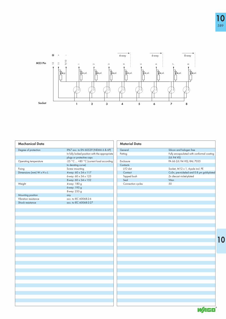
M12 Sensor/Actuator Boxes5-pole, with M23 connection
8-way 6-way 4-way
<_____34_____><___________ 60 ___________> <__22__>
<___________________________ 1
23
___________________________>
<_________________________1
17
_________________________>
<____________________________________1
52
____________________________________>
• 4-, 6- and 8-way sensor/actuator boxes• 5 poles (2 signals per contact)• M23 connector (19 poles)• Green LED operating indicator• Yellow LED status indicator
(does not apply for modules marked as “without LED“)• incl. markers (10 pcs)• incl. M12 protective caps (2 pcs)
Note: Modules without status LED can also be used to transmit analog signals
Description Item No.Pack. Unit
M12 sensor/actuator box
4-way, 5-pole, M23 connector 757-145 1
6-way, 5-pole, M23 connector 757-165 1
8-way, 5-pole, M23 connector 757-185 1
8-way, 5-pole, without LED,
M23 connector
757-185/100-000 1
Accessories Item No.
Marker card, marking pen, spacer module
and protective cap
see page 596
IP67 cables and connectors see page 597 + Section 11
Approvals
r UL 508 E 175199, UL 508, Class 2 Equipment
Components are designed to be supplied
through Class 2 power supplies in
accordance with UL 1310 or Class 2
transformers in accordance with UL 1585
Electrical Data
Contact resistance ≤ 10 mΩ
Operating voltage 10 V ... 30 V DC
Current carrying capacity 2 A per signal; 9 A per SA box
Rated voltage 32 V ~ eff.
Insulation voltage 1 kV / 3 s
Insulation resistance > 109 Ω
Degree of pollution 3 acc. to VDE 0110
Switching function PNP

10591
10
–
1 2 3 4
+
5 6 7 8
2 4 3 5
1
2 4 3 5
1
2 4 3 5
1
2 4 3 5
1
2 4 3 5
1
2 4 3 5
1
2 4 3 5
1
2 4 3 5
1
M23 Pin
Socket
4-way 6-way 8-way12
19
6 15
5 16
3 17
2 11
1
gr. yel. yel. yel. yel. yel. yel. yel. yel.
7 4 8 14
9 13
10 18
yel.
Mechanical Data
Degree of protection IP67 acc. to EN 60529 (NEMA 6 & 6P)
In fully locked position with the appropriate
plugs or protective caps
Operating temperature -25 °C ... +80 °C (current load according
to derating curve)
Fixing Screw mounting
Dimensions (mm) W x H x L 4-way: 60 x 34 x 117
6-way: 60 x 34 x 123
8-way: 60 x 34 x 152
Weight 4-way: 180 g
6-way: 200 g
8-way: 245 g
Mounting position any
Vibration resistance acc. to IEC 60068-2-6
Shock resistance acc. to IEC 60068-2-27
Material Data
General Silicon and halogen free
Potting Fully encapsulated with conformal coating
(UL 94 V0)
Enclosure PA 66 (UL 94 V0); RAL 7035
Contacts
I/O slot Socket, M12 x 1, 5-pole incl. PE
Contact CuSn, pre-nickeled and 0.8 µm gold-plated
Tapped bush Zn diecast nickel-plated
Seal Viton
Connection cycles 50

10592
M8 Sensor/Actuator Boxes3-pole, with cable connection
M8 sensor / actuator box with marker strips 10-way 8-way 6-way 4-way
<____30____> <_18_><__ 20__>
<_________________________________________
17
5_________________________________________>
<_____________________________________1
52_____________________________________>
<_____________________________1
23
_______________________>
<____________________________1
17______________________>
757-403/000-010
• M8 sensor/actuator boxes, 4-, 6-, 8- and 10-way• 3-pole (1 signal per contact)• Cable length 5 m or 10 m (cable end 100 mm stripped),
4-way sensor/actuator box with 2 m connecting cable (cable end 200 mm stripped)
• Green LED operating indicator• Yellow LED status indicator• incl. marker strips (note: WMB markers can also be used)• incl. M8 protective caps (2 pcs)
Description Item No.Pack. Unit
M8 sensor/actuator box
4-way, 3-pole, 2m connecting cable 757-443/000-002 1
4-way, 3-pole, 5m connecting cable 757-443/000-005 1
4-way, 3-pole, 10m connecting cable 757-443/000-010 1
6-way, 3-pole, 5m connecting cable 757-463/000-005 1
6-way, 3-pole, 10m connecting cable 757-463/000-010 1
8-way, 3-pole, 5m connecting cable 757-483/000-005 1
8-way, 3-pole, 10m connecting cable 757-483/000-010 1
10-way, 3-pole, 5m connecting cable 757-403/000-005 1
10-way, 3-pole, 10m connecting cable 757-403/000-010 1
Accessories Item No.
Marker strips, marking pen, spacer
module and protective cap
see page 596
IP67 cables and connectors see page 597 + Section 11
Approvals
r UL 508 E 175199, UL 508, Class 2 Equipment
Components are designed to be supplied
through Class 2 power supplies in
accordance with UL 1310 or Class 2
transformers in accordance with UL 1585
Electrical Data
Contact resistance ≤ 10 mΩ
Operating voltage 10 V ... 30 V DC
Current carrying capacity 2 A per signal; 6 A per SA box
Rated voltage 32 V ~ eff.
Insulation voltage 1 kV / 3 s
Insulation resistance > 109 Ω
Degree of pollution 3 acc. to VDE 0110
Switching function PNP
10593
10
–
1 2 3 4
+
5 6 7 8 9 10
4 3
1
4 3
1
4 3
1
4 3
1
4 3
1
4 3
1
4 3
1
4 3
1
4 3
1
4 3
1
Color ofconductors
Socket
4-way 6-way 8-way
brown
blue
white
green
yellow
grey
pink
red
black
violet
yel.
grey/pink
red/blue
gr.
10-way
yel. yel. yel. yel. yel. yel. yel. yel. yel.
Mechanical Data
Degree of protection IP68 (1 meter water depth for 72 hours)
acc. to EN 60529 In fully locked position
with the appropriate plugs or protective
caps
Operating temperature -25 °C ... +80 °C (current load according
to derating curve)
Fixing Screw mounting
Dimensions (mm) W x H x L 4-way: 30 x 20 x 117
6-way: 30 x 20 x 123
8-way: 30 x 20 x 152
10-way: 30 x 20 x 175
Weight 4-way: 85 g
6-way: 95 g
8-way: 110 g
10-way: 130 g
without cable
Mounting position any
Vibration resistance acc. to IEC 60068-2-6
Shock resistance acc. to IEC 60068-2-27
Material Data
General Silicon and halogen free
Potting Fully encapsulated with conformal coating
(UL 94 V0)
Enclosure PA 66 (UL 94 V0); RAL 7035
Contacts
I/O slot Socket, M8 x 1, 3-pole
Contact CuSn, pre-nickeled and 0.8 µm gold-plated
Tapped bush Zn diecast nickel-plated
Seal Viton
Connection cycles 50
Connecting cable
Cable design
757-443/000-002:
Outer sheath PUR halogen-free
Black
Cable end 100 mm stripped
Cable end 200 mm stripped
Cable Ø 6.4 mm SA box 4-way
7.2 mm SA box 6-way
7.4 mm SA box 8-way
7.6 mm SA box 10-way
Conductor design n x 0.34 mm2 + 2 x 0.75 mm2
conductor 0.34 mm2
extra-fine stranded 43 x 0.1 mm
conductor 0.75 mm2
extra-fine stranded 21 x 0.205 mm
color identification of conductors
Suitable for drag chain applications
bending radius min. 10 x cable Ø
amb. temperature range -40°C ... +90°C stagnant;
-5°C ... +80°C moving

10594
M8 Sensor/Actuator Boxes3-pole, with M16 connection
M8 sensor / actuator box with marker strips 10-way 8-way 6-way 4-way
<____30____> <_18_><__ 26 ___>
<_________________________________________
17
5_________________________________________>
<_____________________________________1
52_____________________________________>
<______________________________1
23_______________________>
<____________________________1
17______________________>
757-303
• M8 sensor/actuator boxes, 4-, 6-, 8- and 10-way• 3-pole (1 signal per contact)• M16 connector (14-pole)• Green LED operating indicator• Yellow LED status indicator• incl. marker strips (note: WMB markers can also be used)• incl. M8 protective caps (2 pcs)
Description Item No.Pack. Unit
M8 sensor/actuator box
4-way, 3-pole, M16 connector 757-343 1
6-way, 3-pole, M16 connector 757-363 1
8-way, 3-pole, M16 connector 757-383 1
10-way, 3-pole, M16 connector 757-303 1
Accessories Item No.
Marker strips, marking pen, spacer
module and protective cap
see page 596
IP67 cables and connectors see page 597 + Section 11
Approvals
r UL 508 E 175199, UL 508, Class 2 Equipment
Components are designed to be supplied
through Class 2 power supplies in
accordance with UL 1310 or Class 2
transformers in accordance with UL 1585
Electrical Data
Contact resistance ≤ 10 mΩ
Operating voltage 10 V ... 30 V DC
Current carrying capacity 2 A per signal; 6 A per SA box
Rated voltage 32 V ~ eff.
Insulation voltage 1 kV / 3 s
Insulation resistance > 109 Ω
Degree of pollution 3 acc. to VDE 0110
Switching function PNP
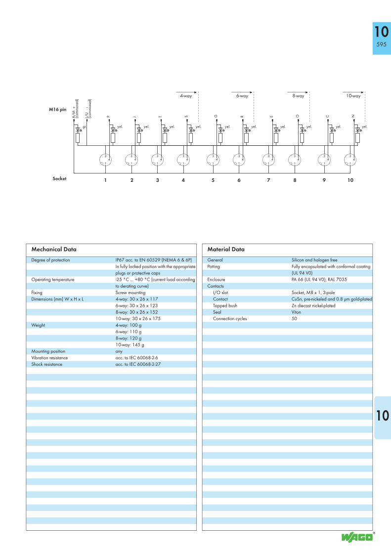
10595
10
–
1 2 3 4
+
5 6 7 8 9 10
4 3
1
4 3
1
4 3
1
4 3
1
4 3
1
4 3
1
4 3
1
4 3
1
4 3
1
4 3
1
P J T S
G
R E O
C
N
M16 pin
Socket
4-way 6-way 8-way
A/M
(commoned)
L/U
(commoned)
yel. yel. yel. yel. yel. yel. yel. yel. yel. yel.gr.
10-way
Mechanical Data
Degree of protection IP67 acc. to EN 60529 (NEMA 6 & 6P)
In fully locked position with the appropriate
plugs or protective caps
Operating temperature -25 °C ... +80 °C (current load according
to derating curve)
Fixing Screw mounting
Dimensions (mm) W x H x L 4-way: 30 x 26 x 117
6-way: 30 x 26 x 123
8-way: 30 x 26 x 152
10-way: 30 x 26 x 175
Weight 4-way: 100 g
6-way: 110 g
8-way: 120 g
10-way: 145 g
Mounting position any
Vibration resistance acc. to IEC 60068-2-6
Shock resistance acc. to IEC 60068-2-27
Material Data
General Silicon and halogen free
Potting Fully encapsulated with conformal coating
(UL 94 V0)
Enclosure PA 66 (UL 94 V0); RAL 7035
Contacts
I/O slot Socket, M8 x 1, 3-pole
Contact CuSn, pre-nickeled and 0.8 µm gold-plated
Tapped bush Zn diecast nickel-plated
Seal Viton
Connection cycles 50

596
10 Accessories for the WAGO-I/O-SYSTEM 757
Marking cards
Marker strips for
Series 757
Marking pen with
fiber tip
Description Item No. Pack. Unit
Marker card (40 tags) for M12 sensor/actuator box 757-011 1
Marker strips for M8 sensor/actuator box 4-way 757-041 100
Marker strips for M8 sensor/actuator box 6-way 757-061 100
Marker strips for M8 sensor/actuator box 8-way 757-081 100
Marker strips for M8 sensor/actuator box 10-way 757-001 100
Marking pen for permanent marking 210-110 1
Spacer module
Description Item No. Pack. Unit
Spacer module for sensor/actuator box 4-way 757-040 10
Spacer module for sensor/actuator box 6-way 757-060 10
Spacer module for sensor/actuator box 8-way (see illustration) 757-080 10
Spacer module for sensor/actuator box 10-way 757-000 10
175 mm (10-way)
152 mm (8-way)
123 mm (6-way)
117 mm (4-way)

597
10
10
WAGO-I/O-SYSTEM 756Distribution cables for the WAGO-I/O-SYSTEM 757
M16 Socket
M16 Distribution cables for connecting M8 sensor /actuator boxes Cable Ø Item No. Pack. Unit
14-pole, M16 socket, straight, one free wire end, 5 m 9.1 mm ± 0.2 756-3205/140-050 1
M16 socket, straight, one free wire end, 10 m 9.1 mm ± 0.2 756-3205/140-100 1
M16 socket, straight, one free wire end, 15 m 9.1 mm ± 0.2 756-3205/140-150 1
M16 Socket
M16 Distribution cables for connecting M8 sensor /actuator boxes Cable Ø Item No. Pack. Unit
14-pole, M16 socket, right angle, one free wire end, 5 m 9.1 mm ± 0.2 756-3206/140-050 1
M16 socket, right angle, one free wire end, 10 m 9.1 mm ± 0.2 756-3206/140-100 1
M16 socket, right angle, one free wire end, 15 m 9.1 mm ± 0.2 756-3206/140-150 1
M23 Socket
M23 Distribution cables for connecting M8 sensor /actuator boxes Cable Ø Item No. Pack. Unit
12-pole, M23 socket, straight, one free wire end, 5 m 8.6 mm ± 0.3 756-3201/120-050 1
M23 socket, straight, one free wire end, 10 m 8.6 mm ± 0.3 756-3201/120-100 1
M23 socket, straight, one free wire end, 15 m 8.6 mm ± 0.3 756-3201/120-150 1
19-pole, M23 socket, straight, one free wire end, 5 m 9.7 mm ± 0.3 756-3203/190-050 1
M23 socket, straight, one free wire end, 10 m 9.7 mm ± 0.3 756-3203/190-100 1
M23 socket, straight, one free wire end, 15 m 9.7 mm ± 0.3 756-3203/190-150 1
M23 Socket
M23 Distribution cables for connecting M8 sensor /actuator boxes Cable Ø Item No. Pack. Unit
12-pole, M23 socket, right angle, one free wire end, 5 m 8.6 mm ± 0.3 756-3202/120-050 1
M23 socket, right angle, one free wire end, 10 m 8.6 mm ± 0.3 756-3202/120-100 1
M23 socket, right angle, one free wire end, 15 m 8.6 mm ± 0.3 756-3202/120-150 1
19-pole, M23 socket, right angle, one free wire end, 5 m 9.7 mm ± 0.3 756-3204/190-050 1
M23 socket, right angle, one free wire end, 10 m 9.7 mm ± 0.3 756-3204/190-100 1
M23 socket, right angle, one free wire end, 15 m 9.7 mm ± 0.3 756-3204/190-150 1
Custom cable lengths upon request
Pin A, L: 0.75 mm²Pin C - J, N - T: 0.34 mm²
A brown N pink-brownC white-pink O violetE black P whiteG pink R redJ green S grayL blue T yellowM commoned with A U commoned with L
<______________________________>
<______________________>
<______>
64
50
20
,2
14-pole
Pin A, L: 0.75 mm²Pin C - J, N - T: 0.34 mm²
A brown N pink-brownC white-pink O violetE black P whiteG pink R redJ green S grayL blue T yellowM commoned with A U commoned with L
<_____________________>
<______________>
<______>
<____________________>
45
48,5
34,2
20,2 14-pole
12-pole
19-pole
Pin 9, 11, 12: 1.00 mm²; Pin 1 - 8: 0.34 mm²1 white 5 pink 9 blue2 green 6 red 10 commoned with 93 yellow 7 black 11 brown4 gray 8 violet 12 green-yellow
Pin 6, 12, 19: 1.00 mm²; Pin 1 - 5, 7 - 11, 13 - 19: 0.34 mm²1 violet 8 white-green 15 white2 red 9 white-yellow 16 yellow3 gray 10 white-gray 17 pink4 red-blue 11 black 18 gray-brown5 green 12 green-yellow 19 brown6 blue 13 yellow-brown7 gray-pink 14 brown-green
<________________________________________>
<_________>
85
Ø 2
6
12-pole
19-pole
Pin 9, 11, 12: 1.00 mm²; Pin 1 - 8: 0.34 mm²1 white 5 pink 9 blue2 green 6 red 10 commoned with 93 yellow 7 black 11 brown4 gray 8 violet 12 green-yellow
Pin 6, 12, 19: 1.00 mm²; Pin 1 - 5, 7 - 11, 13 - 19: 0.34 mm²1 violet 8 white-green 15 white2 red 9 white-yellow 16 yellow3 gray 10 white-gray 17 pink4 red-blue 11 black 18 gray-brown5 green 12 green-yellow 19 brown6 blue 13 yellow-brown7 gray-pink 14 brown-green
<__________>Ø 26
<_________________________________>
<______________________>
70
50
598
10 WAGO-I/O-SYSTEM 756Distribution cables for the WAGO-I/O-SYSTEM 757
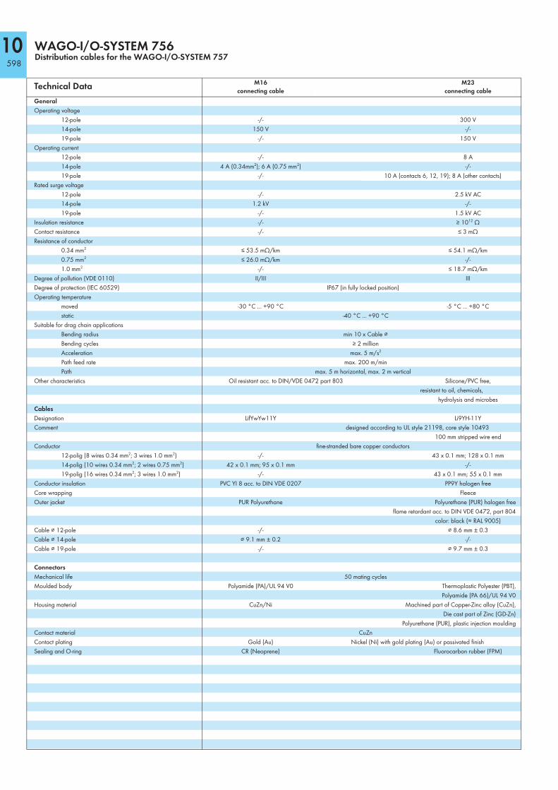
Technical Data M16
connecting cable
M23
connecting cable
General
Operating voltage
12-pole -/- 300 V
14-pole 150 V -/-
19-pole -/- 150 V
Operating current
12-pole -/- 8 A
14-pole 4 A (0.34mm2); 6 A (0.75 mm2) -/-
19-pole -/- 10 A (contacts 6, 12, 19); 8 A (other contacts)
Rated surge voltage
12-pole -/- 2.5 kV AC
14-pole 1.2 kV -/-
19-pole -/- 1.5 kV AC
Insulation resistance -/- ≥ 1012 Ω
Contact resistance -/- ≤ 3 mΩ
Resistance of conductor
0.34 mm2 ≤ 53.5 mΩ/km ≤ 54.1 mΩ/km
0.75 mm2 ≤ 26.0 mΩ/km -/-
1.0 mm2 -/- ≤ 18.7 mΩ/km
Degree of pollution (VDE 0110) II/III III
Degree of protection (IEC 60529) IP67 (in fully locked position)
Operating temperature
moved -30 °C ... +90 °C -5 °C ... +80 °C
static -40 °C ... +90 °C
Suitable for drag chain applications
Bending radius min 10 x Cable ⌀
Bending cycles ≥ 2 million
Acceleration max. 5 m/s2
Path feed rate max. 200 m/min
Path max. 5 m horizontal, max. 2 m vertical
Other characteristics Oil resistant acc. to DIN/VDE 0472 part 803 Silicone/PVC free,
resistant to oil, chemicals,
hydrolysis and microbes
Cables
Designation LifYwYw11Y Li9YH-11Y
Comment designed according to UL style 21198, core style 10493
100 mm stripped wire end
Conductor fine-stranded bare copper conductors
12-polig (8 wires 0.34 mm2; 3 wires 1.0 mm2) -/- 43 x 0.1 mm; 128 x 0.1 mm
14-polig (10 wires 0.34 mm2; 2 wires 0.75 mm2) 42 x 0.1 mm; 95 x 0.1 mm -/-
19-polig (16 wires 0.34 mm2; 3 wires 1.0 mm2) -/- 43 x 0.1 mm; 55 x 0.1 mm
Conductor insulation PVC YI 8 acc. to DIN VDE 0207 PP9Y halogen free
Core wrapping Fleece
Outer jacket PUR Polyurethane Polyurethane (PUR) halogen free
flame retardant acc. to DIN VDE 0472, part 804
color: black (≈ RAL 9005)
Cable ⌀ 12-pole -/- ⌀ 8.6 mm ± 0.3
Cable ⌀ 14-pole ⌀ 9.1 mm ± 0.2 -/-
Cable ⌀ 19-pole -/- ⌀ 9.7 mm ± 0.3
Connectors
Mechanical life 50 mating cycles
Moulded body Polyamide (PA)/UL 94 V0 Thermoplastic Polyester (PBT),
Polyamide (PA 66)/UL 94 V0
Housing material CuZn/Ni Machined part of Copper-Zinc alloy (CuZn),
Die cast part of Zinc (GD-Zn)
Polyurethane (PUR), plastic injection moulding
Contact material CuZn
Contact plating Gold (Au) Nickel (Ni) with gold plating (Au) or passivated finish
Sealing and O-ring CR (Neoprene) Fluorocarbon rubber (FPM)