sensor access website - cabriggs.com · alarms and documentation ... welcome to the sensor access...
TRANSCRIPT

User Guide
Revision A.0
Sensor Access Website

Sensor Access Guide 2
Contents
Welcome to the Sensor Access system ................................................................................................................................... 4
Sensor Access Website Login .................................................................................................................................................. 4
Registering (Creating an Account) .................................................................................................................................. 4
Password Reset ............................................................................................................................................................... 4
Sensor Access User Guide ............................................................................................................................................... 4
Sensor Access Website Menus ............................................................................................................................................... 5
Main Menu .............................................................................................................................................................................. 6
Sensor Menu ................................................................................................................................................................... 6
Alarm History .................................................................................................................................................................. 6
Log Out ............................................................................................................................................................................ 6
Sensor Menu ........................................................................................................................................................................... 7
Adding a Sensor .............................................................................................................................................................. 7
Serial Number List ........................................................................................................................................................... 7
Measurement Menu ............................................................................................................................................................... 8
Measurement History ............................................................................................................................................................. 9
History Menu ...................................................................................................................................................................... 9
Level Graphs .................................................................................................................................................................... 9
Distance Graphs .............................................................................................................................................................. 9
Level and Distance Graphs .............................................................................................................................................. 9
View Calibration .................................................................................................................................................................... 10
Edit Calibration ...................................................................................................................................................................... 10
Alarm Menu .......................................................................................................................................................................... 11
Diagnostic .............................................................................................................................................................................. 11
Help ....................................................................................................................................................................................... 12
Alarm Section ........................................................................................................................................................................ 13
Quick Alarm Setup ................................................................................................................................................................ 13
Alarms and Documentation .............................................................................................................................................. 13
Alarm Email ....................................................................................................................................................................... 13
Sensor Range ..................................................................................................................................................................... 13
Sensor Name & Location ................................................................................................................................................... 13
Sensor Alarm Setup ........................................................................................................................................................... 13
View Alarm Summary ........................................................................................................................................................ 14

Sensor Access Guide 3
Calibration Secton ................................................................................................................................................................ 15
Calibration Menu .................................................................................................................................................................. 15
How To Setup Your Tank ................................................................................................................................................... 16
Tank Range or Sensor Calibration Range .......................................................................................................................... 16
Set Empty Tank ................................................................................................................................................................. 17
Set Full Tank ...................................................................................................................................................................... 17
Damping ............................................................................................................................................................................ 18
Full Tank Blanking ............................................................................................................................................................. 18
Time Between Measurements .......................................................................................................................................... 19
Data Logging ...................................................................................................................................................................... 20
Units of Measure ............................................................................................................................................................... 20
Button Control .................................................................................................................................................................. 21
Vaporized Liquid/Self Cleaning (Ultrasonic Sensors) ........................................................................................................ 22
Solid & Liquid Material (Ultrasonic Sensors) .................................................................................................................... 22
Diagnostic Section ................................................................................................................................................................. 23
Diagnostics ............................................................................................................................................................................ 23
Understanding Distance and Level Section........................................................................................................................... 24
Understanding Distance and Level ....................................................................................................................................... 24
Tank Properties ............................................................................................................................................................. 24
Level .............................................................................................................................................................................. 25

Sensor Access Guide 4
Welcome to the Sensor Access system This guide will provide a brief overview of the Sensor Access Website and its menus. The guide is brief because most of
the pages in the Sensor Access system include documentation.
Thank you for purchasing a cellular enabled remote sensor unit. Your sensor will automatically connect to the Sensor
Access system updating the system with measurements and downloading any new configuration changes you may have
added. From the Sensor Access Website you can see the latest measurement, lists of historical measurements, graphs
and diagnostic information. To get started you will need to create an account which can be done from our login page.
Sensor Access Website Login
Figure 1 The Sensor Access login page provides access to the Sensor Access system.
To access the Sensor Access Website click here.
To use the Sensor Access Website you must create an account. If you do not have account see the registration section
below. To login to the Sensor Access Website enter your email address and your password and click the login button
(see Figure 1). Once you have logged in you will be at the main menu. Click here to see an overview of the Website
menus, or click here to go the main menu in this document.
Registering (Creating an Account)
You can create an account by clicking on registration link “Register Here” as seen in Figure 1. Clicking the “Register Here”
link on the login screen will open the new user registration page. To complete the registration process you will need the
Sensor Access Code that came with your sensor.
Password Reset
If you have forgotten your password you can use the “Reset Password” link. An email will be sent with instructions.
Sensor Access User Guide
A copy of this guide is available from the Login page by clicking on the “View” link.

Sensor Access Guide 5
Sensor Access Website Menus The following diagrams and text will help you navigate through the Sensor Access Website. Figure 2 shows a partial
schematic of the Sensor Access Website. The login form has links to the Registration Form to create an account, the
Password Reset Form is available if you forgot your password and the Main Menu is the screen you will see after you
login.
Figure 2 Login Form and Menus

Sensor Access Guide 6
Main Menu
Sensor Menu
Alarm History
Log Out
Main Menu
Back
Add a Sensor
Log Out
Sensor Menu
251217001
Serial Number List
Alarm History
Figure 3 Main menu shown in the upper left provides access to the sensor menu and the alarm history menu.
After you have logged in you will see the “Main Menu” as shown in Figure 3. The top of the tab in your browser window
will be titled “Main Menu”. From the main menu you can chose to log out, move to the “Sensor Menu” or view “Alarm
History”.
Sensor Menu
The sensor menu provides access to each of the sensor you have registered to your account. Click this menu if you want
to view or add a sensor. (Click here to jump to Sensor Menu)
Alarm History
If you have enabled alarms with any of your sensors and an alarm event has occurred you will be able to view historical
alarm events using this menu item.
Log Out
Clicking on Log Out will log you out of the Sensor Access system. You should always click the log out menu item when
you are done working with your account.
Sensor Access Guide 7
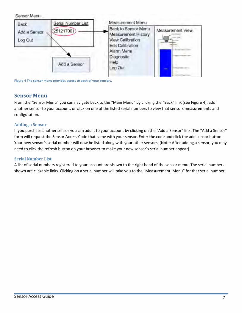
Figure 4 The sensor menu provides access to each of your sensors.
Sensor Menu From the “Sensor Menu” you can navigate back to the “Main Menu” by clicking the “Back” link (see Figure 4), add
another sensor to your account, or click on one of the listed serial numbers to view that sensors measurements and
configuration.
Adding a Sensor
If you purchase another sensor you can add it to your account by clicking on the “Add a Sensor” link. The “Add a Sensor”
form will request the Sensor Access Code that came with your sensor. Enter the code and click the add sensor button.
Your new sensor’s serial number will now be listed along with your other sensors. (Note: After adding a sensor, you may
need to click the refresh button on your browser to make your new sensor’s serial number appear).
Serial Number List
A list of serial numbers registered to your account are shown to the right hand of the sensor menu. The serial numbers
shown are clickable links. Clicking on a serial number will take you to the “Measurement Menu” for that serial number.
Sensor Access Guide 8
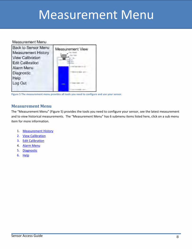
Figure 5 The measurement menu provides all tools you need to configure and use your sensor.
Measurement Menu The “Measurement Menu” (Figure 5) provides the tools you need to configure your sensor, see the latest measurement
and to view historical measurements. The “Measurement Menu” has 6 submenu items listed here, click on a sub menu
item for more information.
1. Measurement History
2. View Calibration
3. Edit Calibration
4. Alarm Menu
5. Diagnostic
6. Help
Measurement Menu

Sensor Access Guide 9
Measurement History
Figure 6 The history menu provides historical measurements in list form or graphs.
History Menu The history menu items (Figure 6 right side) allow you to view measurement history in one of three formats as show in
Error! Reference source not found.. The measurement list provides historical measurements data formatted in a tabular
layout. There are two options to view historical data as a graph based on distance or level.
Level Graphs
The “level” graph shows the level of the material in the tank measured from the bottom of the tank. The “level” value is
a calculated value based on the tank size. For accurate level information see the “Level and Distance Graphs” section
below.
Distance Graphs
The distance graph shows the distance of the material in the tank as measured from the sensor. For accurate distance
information see the “Level and Distance Graphs” section below.
Level and Distance Graphs
When viewing a graph you can use your mouse to click on the graph line to see the actual reading. For an accurate level
calculations and percent full calculations you should use the “set tank range” form, found in “Calibration Menu” or the
“sensor range” form found in the “Alarm Menu” to setup your tank size parameters.

Sensor Access Guide 10
View Calibration The calibration view page shows your sensor current configuration (Figure 7). The full tank and empty tank distances can
be configured to match your application. Please note that changes made to the sensors configuration will not appear
until the sensor connects to the access server and downloads the changes.
Measurement Menu
Measurement ViewBack to Sensor Menu
Measurement History
View Calibration
Edit Calibration
Alarm Menu
Diagnostic
Help
Log Out
Back
Calibration View
Figure 7 The calibration view page shows the current configuration of your sensor.
Edit Calibration
Measurement Menu
Measurement ViewBack to Sensor Menu
Measurement History
View Calibration
Edit Calibration
Alarm Menu
Diagnostic
Help
Log Out
BackSet Tank Range
Set Empty Tank
Set Full Tank
Set Damping
Full Tank Blanking
Time Between Measurements
Data Logging
Units (FT,IN,M,CM)
Button Control
Vaporized Liquids
Solid & Liquid Material
Calibration Menu
Figure 8 Sensor configuration can be changed at anytime using the Edit Calibration menu.
Clicking on the Edit Calibration menu item will display the Calibration menu. The calibration menu will allow you to
change the configuration of your sensor. Click here to move to the Calibration Section of this guide.
Sensor Access Guide 11
Alarm Menu
Alarm Menu
Measurement
View
Back to Measurement Menu
1. Alarm Email
2. Sensor Range
3. Sensor Name & Location
4. Sensor Alarm Setup
5. View Alarm Summary
Back to Sensor Menu
Measurement History
View Calibration
Edit Calibration
Alarm Menu
Diagnostic
Help
Log Out
Measurement Menu
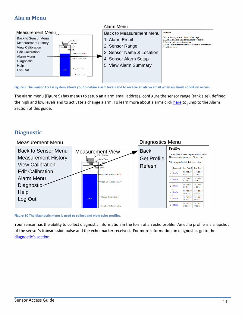
Figure 9 The Sensor Access system allows you to define alarm levels and to receive an alarm email when an alarm condition occurs.
The alarm menu (Figure 9) has menus to setup an alarm email address, configure the sensor range (tank size), defined
the high and low levels and to activate a change alarm. To learn more about alarms click here to jump to the Alarm
Section of this guide.
Diagnostic
Measurement Menu
Measurement ViewBack to Sensor Menu
Measurement History
View Calibration
Edit Calibration
Alarm Menu
Diagnostic
Help
Log Out
Diagnostics Menu
Back
Get Profile
Refesh
Figure 10 The diagnostic menu is used to collect and view echo profiles.
Your sensor has the ability to collect diagnostic information in the form of an echo profile. An echo profile is a snapshot
of the sensor’s transmission pulse and the echo marker received. For more information on diagnostics go to the
diagnostic’s section.

Sensor Access Guide 12
Help
Measurement Menu
Measurement ViewBack to Sensor Menu
Measurement History
View Calibration
Edit Calibration
Alarm Menu
Diagnostic
Help
Log Out
Measurement Terminology
Back
Figure 11 The help menu provides information and definitions for the terminology used with tanks and sensors.
The help menu provides diagrams and definitions for the commonly used sensor and tank terminology.

Sensor Access Guide 13
Alarm Section
Quick Alarm Setup
Figure 12 A quick navigation guide to get to the alarm menu.
Alarms and Documentation Figure 12 show the menu selections required to get to the alarm menu. There are 5 menu items available once you have
setup an alarm email address. The alarm menus descriptions provided in this guide are very brief. You will find the alarm
menu pages are well documented.
Alarm Email The first step to setting up alarms is to add an alarm email address. When an alarm occurs an email is generated and
sent to the registered alarm email address. The alarm email address will require validation before it can be made active.
After adding the email address the Sensor Access system will send a validation email to this address. Follow the
instructions in the validation email to complete the email registration.
Sensor Range For accurate reporting you should configure your sensors range. The range values you enter tell the sensor when your
tank is full and when your tank is empty.
Sensor Name & Location The sensor name and location fields allow you to name your sensor and provide location information. When alarm
conditions occurs both the name and location information you provide will be in the email.
Time zone – By default your sensor uses eastern standard time (EST). All measurements will be reported with an EST
timestamp. You can configure your sensor to report time in any time zone you desire.
Sensor Alarm Setup This menu item will not appear until you have added an email address to the system. The alarm setup menu allows you
to select the alarms notifications you would to receive.
There are 5 alarms:
Full Tank alarm – Sends an alarm message when the material in your tank reach the full tank point.
Alarm Section
Sensor Access Guide 14
High Level Alarm – The high level point can be configured for any level that is between the full tank level and low
level level. When the material in your tank crosses the high level point an alarm condition will occur.
Low Level Alarm – The low level point can be configured for any level that is between the high level and the empty
tank level. When the material in your tank crosses the low level point an alarm condition will occur.
Empty Tank alarm – Sends an alarm message when the material in your tank reach the empty tank level.
Change Alarm – The change alarm system monitors your tank for changes after your office closes.
View Alarm Summary You can view your alarm configuration at any time by using the View Alarm Summary menu item.

Sensor Access Guide 15
Calibration Secton
BackSet Tank Range
Set Empty Tank
Set Full Tank
Set Damping
Full Tank Blanking
Time Between Measurements
Data Logging
Units (FT,IN,M,CM)
Button Control
Vaporized Liquids
Solid & Liquid Material
Calibration Menu
Figure 13 Overview of the Calibration Menu
Calibration Menu Your sensor has many programmable features as show in Figure 13. The calibration menus allow you to configure these
different configuration items to match your needs.
Configuration Items
How to setup your tank
Tank Range
Set Empty Tank Distance to current tank level
Set Full Tank Distance to current tank level
Set Damping to average out the level of material that shift or move due to waves.
Use Full Tank Blanking to ignore unwanted echoes near the full tank level.
Time between Measurements
Data Logging
Units of measure
Button Control
Vaporized Liquids
Solid & Liquid Material
Calibration Section
Sensor Access Guide 16
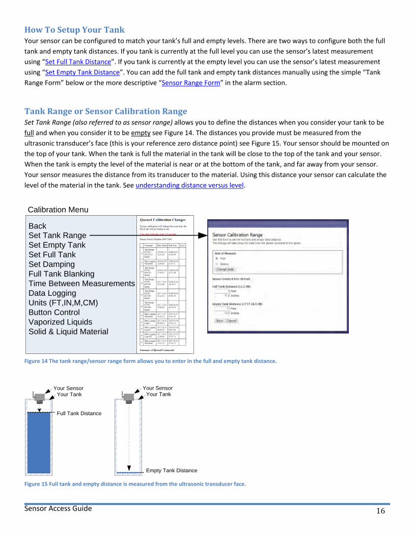
How To Setup Your Tank Your sensor can be configured to match your tank’s full and empty levels. There are two ways to configure both the full
tank and empty tank distances. If you tank is currently at the full level you can use the sensor’s latest measurement
using “Set Full Tank Distance”. If you tank is currently at the empty level you can use the sensor’s latest measurement
using “Set Empty Tank Distance”. You can add the full tank and empty tank distances manually using the simple “Tank
Range Form” below or the more descriptive “Sensor Range Form” in the alarm section.
Tank Range or Sensor Calibration Range Set Tank Range (also referred to as sensor range) allows you to define the distances when you consider your tank to be
full and when you consider it to be empty see Figure 14. The distances you provide must be measured from the
ultrasonic transducer’s face (this is your reference zero distance point) see Figure 15. Your sensor should be mounted on
the top of your tank. When the tank is full the material in the tank will be close to the top of the tank and your sensor.
When the tank is empty the level of the material is near or at the bottom of the tank, and far away from your sensor.
Your sensor measures the distance from its transducer to the material. Using this distance your sensor can calculate the
level of the material in the tank. See understanding distance versus level.
BackSet Tank Range
Set Empty Tank
Set Full Tank
Set Damping
Full Tank Blanking
Time Between Measurements
Data Logging
Units (FT,IN,M,CM)
Button Control
Vaporized Liquids
Solid & Liquid Material
Calibration Menu
Figure 14 The tank range/sensor range form allows you to enter in the full and empty tank distance.
Empty Tank Distance
Your SensorYour Tank
Full Tank Distance
Your SensorYour Tank
Figure 15 Full tank and empty distance is measured from the ultrasonic transducer face.

Sensor Access Guide 17
Set Empty Tank The empty tank distance can be programmed to use the current target distance by clicking on the “Set Empty tank”
menu item and selecting yes and save from the empty tank calibration form shown in Figure 16 (right side). The empty
tank calibration will occur the next time the sensor connects to the access server and downloads the configuration
change.
BackSet Tank Range
Set Empty Tank
Set Full Tank
Set Damping
Full Tank Blanking
Time Between Measurements
Data Logging
Units (FT,IN,M,CM)
Button Control
Vaporized Liquids
Solid & Liquid Material
Calibration Menu
Figure 16 Set empty tank provides a simple way to set the empty tank distance using the sensor's current distance.
Set Full Tank The full tank distance can be programmed to use the current target distance by clicking on the “Set Full Tank” menu
item and selecting yes and save from the full tank calibration form shown in Figure 17 (right side). The full tank
calibration will occur the next time the sensor connects to the access server and downloads the configuration change.
BackSet Tank Range
Set Empty Tank
Set Full Tank
Set Damping
Full Tank Blanking
Time Between Measurements
Data Logging
Units (FT,IN,M,CM)
Button Control
Vaporized Liquids
Solid & Liquid Material
Calibration Menu
Figure 17 The set full tank calibration form provides a simple way to set the full tank distance using the sensor's current distance.

Sensor Access Guide 18
Damping In some applications the material being sensed changes in position or shape due to the process being applied or the
environment where the material is stored. Liquid material can be disturbed by waves and solid materials can shift. If the
surface of the material being sensed changes frequently then the distance being measured by the sensor will fluctuate
frequently. Set damping to average out the level of the material that shift’s or moves due to waves. Using the lowest
damping factor of 2 seconds provides the fastest response and helps reduce measurement fluctuations. A damping
factor of 10 provides a relatively stable reading. Entering higher values will reduce the sensor response time.
To change the sensor’s damping factor click the “Set Damping” link. The damping form will appear as shown in Figure 18
(right side). Damping can be turned off by unchecking the “Damping Enabled” box. If damping is enabled a value in the
range of 2 to 255 can be entered. Recall that the higher the damping value the slower the response. After entering a
damping factor click the “Save” button.
BackSet Tank Range
Set Empty Tank
Set Full Tank
Set Damping
Full Tank Blanking
Time Between Measurements
Data Logging
Units (FT,IN,M,CM)
Button Control
Vaporized Liquids
Solid & Liquid Material
Calibration Menu
Figure 18 Damping allows the sensor to average measurements over time.
Full Tank Blanking Full Tank Blanking must be used with some caution. The blanking feature is used to ignore unwanted echoes which are
closer than the full tank calibration minus 3 inches. As shown in Figure 19 the feature can be accessed by clicking on the
“Full Tank Blanking”. The blanking feature must not be used when calibrating the sensor using the sensor push button.
BackSet Tank Range
Set Empty Tank
Set Full Tank
Set Damping
Full Tank Blanking
Time Between Measurements
Data Logging
Units (FT,IN,M,CM)
Button Control
Vaporized Liquids
Solid & Liquid Material
Calibration Menu
Figure 19 Full Tank Blanking control page shows the current state and allows the feature to be turned on or off.

Sensor Access Guide 19
Time Between Measurements Your sensor has been designed to operate for long periods from a battery. The largest power consumption occurs when
the embedded cellular modem is powered on and communicating with the Sensor Server. To save battery power your
sensor switches to a low power mode and sleeps between measurements.
The sensor’s normal operation is to:
1. Wake from sleep.
2. Take a measurement.
3. Save the measurement to data logger memory
4. Check if it should connect to the Sensor Server
a. Connect to Sensor Server
b. Transfer measurement data
5. Go back to sleep.
How long your sensor sleeps between measurements is controlled by the value you enter in to the “Time Between
Measurements” setting see Figure 20. As shown in Figure 20 the sensor can be configure to sleep from 2 minutes to 24
hours. How often the sensor connects to the Sensor Server using the cellular modem is a combination data logging and
the time between measurements.
BackSet Tank Range
Set Empty Tank
Set Full Tank
Set Damping
Full Tank Blanking
Time Between Measurements
Data Logging
Units (FT,IN,M,CM)
Button Control
Vaporized Liquids
Solid & Liquid Material
Calibration Menu
Figure 20 Time Between Measurements defines how often your sensor will wake up and take a measurement.

Sensor Access Guide 20
Data Logging Your sensor has been designed to operate for long periods off of a battery. The largest power consumption occurs when
the embedded cellular modem is powered on and communicating with the Sensor Server. Using data logging combined
with Time Between Measurements you can control how often the cellular modem connects to the Sensor Server. Your
sensor can be configured to log up to 300 measurements before powering on the cellular modem and connecting to the
Sensor Server. With data logging enabled and set to 5 (see Figure 21) your sensor will sleep in a low power mode for
period of time you define (see Time Between Measurements) then wake up and take a measurement, save that
measurement to memory and return to sleep. This will occur 5 times before the sensor powers on the cellular modem
and sends the measurement results to the Sensor Server.
BackSet Tank Range
Set Empty Tank
Set Full Tank
Set Damping
Full Tank Blanking
Time Between Measurements
Data Logging
Units (FT,IN,M,CM)
Button Control
Vaporized Liquids
Solid & Liquid Material
Calibration Menu
Figure 21 Data logging defines how many measurements will be saved in memory before the sensor connects to the server.
Units of Measure
BackSet Tank Range
Set Empty Tank
Set Full Tank
Set Damping
Full Tank Blanking
Time Between Measurements
Data Logging
Units (FT,IN,M,CM)
Button Control
Vaporized Liquids
Solid & Liquid Material
Calibration Menu
Figure 22 Measurements can be reported in inches, feet, centimeters or meters.
Your Sensor can be programmed to report measurements in feet, meters, inches or centimeters as shown in Figure 22.
The default value is feet.

Sensor Access Guide 21
Button Control
BackSet Tank Range
Set Empty Tank
Set Full Tank
Set Damping
Full Tank Blanking
Time Between Measurements
Data Logging
Units (FT,IN,M,CM)
Button Control
Vaporized Liquids
Solid & Liquid Material
Calibration Menu
Figure 23 The calibration button on your sensor can be enable or disabled.
Your sensor is equipped with a calibration button that can be used to calibrate the sensor’s range. For remote locations
the button should be disabled to prevent tampering. To change the button settings click the “Button Control” menu and
select enable or disable from the button control form that appears as shown in Figure 23.
To access the calibration button on the sensor remove the sensors lid by unscrewing it. To make calibration changes to
the sensor using the button, power must be supplied to the sensor and the button must be pressed for time specified in
Table 1. Press the button until the LED turns the desired color and then release the button.
Table 1 Calibration Button
Button Timing of the Remote Ultrasonic Sensor.
Seconds Pressed LED Color Description
< 2 Off If the button is pressed for less than 2 seconds it is ignored and no action is taken.
> 2 Green Take a measurement and connect to the server now.
> 7 Yellow Program the full tank distance equal to the current distance.
> 12 Red Program the empty tank distance equal to the current distance.
> 17 Off Button pressed for greater than 17 seconds are ignored and no action is taken
Where: < means less than and > means greater than.

Sensor Access Guide 22
Vaporized Liquid/Self Cleaning (Ultrasonic Sensors)
BackSet Tank Range
Set Empty Tank
Set Full Tank
Set Damping
Full Tank Blanking
Time Between Measurements
Data Logging
Units (FT,IN,M,CM)
Button Control
Vaporized Liquids
Solid & Liquid Material
Calibration Menu
Figure 24 Self-Cleaning / Vaporized Liquids feature provides periodic cleaning to the transducer face. This feature is ideally suited for applications in environments with high moisture.
The self-cleaning / vaporized liquids feature provides periodic cleaning of the ultrasonic transducer. This feature is highly
recommended for applications where the ultrasonic sensor is exposed to vaporized liquids that cause condensation on
the transducer’s face. The vaporized /self-cleaning feature can be enabled or disabled as shown in Figure 24.
Solid & Liquid Material (Ultrasonic Sensors)
BackSet Tank Range
Set Empty Tank
Set Full Tank
Set Damping
Full Tank Blanking
Time Between Measurements
Data Logging
Units (FT,IN,M,CM)
Button Control
Vaporized Liquids
Solid & Liquid Material
Calibration Menu
Figure 25 High energy pulses can be enabled to propagate through dust and moisture.
In dusty, high moisture environments it is recommended that the “Solid/Liquid Material” feature be turned on.
When enabled the sensor can detect the accumulation of dust or moisture on the transducer face and transmit high
energy pulses that propagate through dust and moisture and clean the transducer face. The self-cleaning feature is
turned off by default. To turn on the self-cleaning feature the “Solid & Liquid Material” feature must be enabled using
the “Solid & Liquid Material” menu as shown in Figure 25.

Sensor Access Guide 23
Diagnostic Section
Figure 26 The Diagnostic menu provides tools to collect and view ech profiles. As profiles are collected they are listed to the right of the menus.
Diagnostics As shown in Figure 26 the diagnostic menu provides the ability to have the sensor collect an echo profile. When a profile
has been requested the request will be queued until the sensor connects to the server. When the sensor connects to the
server the sensor will download the queued command, gather an echo profile, update the sensor server and the profile
will be available for viewing by clicking the “Profile” of your choice.
Diagnostic Section

Sensor Access Guide 24
Understanding Distance and Level Section
Understanding Distance and Level When looking at a tank like the one in Figure 27 there are two distance values used to describe the material in the tank.
The “distance from the sensor” to the material is the actual “distance” measured by the sensor. In this document and on
the Sensor Access Website distance always refers to the distance from the sensor to the material. The distance can be
thought of as the empty space above the material. This value is useful when you want to know how much room is
available in the tank for filling purposes.
Bottom
Material
Sensor
Top
Distance from Sensor
(Distance)
Distance from Bottom
(Level)
Figure 27 Distances used to describe tank material position.
Bottom
Sensor
Top
Sensor
Range
Dead Zone
Full Level
Empty Level
Distance to full
Dis
tance
to e
mpty
Figure 28 Tank properties, full and empty tank levels.
Tank Properties Figure 28 shows a tank with the top, bottom, full level, empty level and the dead zone marked. The dead zone is a small zone below the sensor face where material cannot be detected. The tank height is the distance from the ultrasonic transducer face to the bottom of the tank. This distance can be used as the empty level. The full level is the distance from the sensor to the level considered full. The full level must be below the dead zone. The full level and the empty level are both programmable.
Distance versus Level Section
Sensor Access Guide 25
Level
Level is always measured from the bottom of the tank. Level is used to describe how full a tank is. The level of a tank is a
simple calculation.
Level = (Distance to empty) minus (current distance)
If the level displayed on the Sensor Access Website is high or low in comparison with the actual level in the tank then the
tank range needs to be corrected.