sentry™ visibility sensor user’s guidea).pdf · 73000 sentry™ visibility sensor user’s...
TRANSCRIPT

R.M. YOUNG COMPANY2801 AERO PARK DRIVE
TRAVERSE CITY, MICHIGAN 49686, USA
TEL: (231) 946-3980FAX: (231) 946-4772
WEB: www.youngusa.com
The Sentry optics MUST be kept
clean for proper operation. See
Section 5.3 for cleaning instructions!
Sentry™ Visibility SensorUser’s Guide
73000Analog Output Version
(Ref SVS1)
PN: 73000-90 REV: A051316

This equipment is in compliance with the essential requirements and other provisions of Low Voltage Directives 73/23/EEC and 89/336/EEC as amended by Directive 93/68/EEC.
WEEE and RoHS Statement
R.M. Young Company is pursuing compliance with human safety and environmental protection initiatives by the European Union, known in the industry as WEEE and RoHS. Effective 1 January 2006 our company and products will comply with the WEEE directive 2002/96/EC. We are currently exempt from RoHS requirements because our products broadly fall under Annex 1A, Section 9 - Monitoring and Control Instruments.Despite our current exempt status, we are actively moving towards RoHS compliance.
Notes - Cautions – Warnings
This User’s Guide clearly marks notes, cautions, and warnings. R.M. Young Company recommends that the user read the complete User’s Guide before proceeding with the sensor installation and maintenance. Areas in the User’s Guide that involve potential contact with high voltage are clearly marked with the following label. Verify that AC power is OFF before proceeding with installation and maintenance of the sensor. If you have a question, please call us at 231-946-3980.

i 73000-90(A)
Table of Contents 1.0 Introduction ........................................................................................................... 1
1.1 How the Sentry™ Works ................................................................................... 2 1.2 Specifications of the Sentry™ ........................................................................... 2
1.2.1 Description of Options & Accessories ........................................................ 4 1.2.1.1 Power Supply Options ............................................................................ 4 1.2.1.2 Analog Options ....................................................................................... 5 1.2.1.3 Hood Heater Options .............................................................................. 6 1.2.1.4 Accessories ............................................................................................ 7
1.3 Sensor Description ............................................................................................ 8 1.4 Signal Flow ..................................................................................................... 14
2.0 Installation .......................................................................................................... 15 2.1 Site Preparation .............................................................................................. 15
2.1.1 Siting Guidelines ...................................................................................... 15 2.1.2 Site Preparation ....................................................................................... 17
2.2 Mechanical Installation .................................................................................... 18 2.3 Signal Wiring ................................................................................................... 19
2.3.1 Analog Voltage Output Connection .......................................................... 19 2.3.2 4-20 ma Current Loop Output Connection ............................................... 21 2.3.3 3-Relay Output Connection for 74031-06 PCB ........................................ 23
2.4 Electrical Power Installation ............................................................................ 25 2.4.1 AC Power Connections ............................................................................ 25 2.4.2 DC Power Connections (Optional) ........................................................... 26 2.4.3 Earth Grounding Connections .................................................................. 28
3.0 Data Interpretation and Operation ...................................................................... 29 3.1 Analog Voltage Output .................................................................................... 29 3.2 4-20 ma Current Loop Output (Optional) ........................................................ 34 3.3 74031-06 3-Relay Output (Optional) ............................................................... 38
4.0 Calibration .......................................................................................................... 41 4.1 Procedure for Calibrating the Analog Voltage Output Sentry™ Sensor .......... 42 4.2 Procedure for Calibrating the Sentry™ with 4-20 ma Current Output ............. 45
5.0 Maintenance ....................................................................................................... 47 5.1 EnviroTech Sensor, Inc. Product Warranty: .................................................... 47 5.2 Correcting Defects Under the Warranty .......................................................... 47 5.3 Preventative Maintenance............................................................................... 48 5.4 Corrective Maintenance .................................................................................. 49
5.4.1 Initial Checks ........................................................................................... 49 5.4.2 Test Points ............................................................................................... 49 5.4.3 Troubleshooting Scenarios ...................................................................... 52 5.4.4 Remove & Replace Instructions ............................................................... 53
5.5 Field Replaceable Units (FRU’s) ..................................................................... 55 5.6 Training ........................................................................................................... 55
Appendix ....................................................................................................................... 56

ii 73000-90(A)
List of Figures Figure 1.1-1 Forward Scatter Geometry ................................................................................................... 2 Figure 1.2.1-1 Sensor Label ...................................................................................................................... 4 Figure 1.3-1 Sentry™ Major Components ............................................................................................... 9 Figure 1.3-2 Main Enclosure Components (AC Power Version) ......................................................... 11 Figure 1.3-3 Main Enclosure Components (DC Power Version) ......................................................... 13 Figure 1.4-1 Sentry™ Signal Flow Diagram........................................................................................... 14 Figure 2.1.1-1 Sensor Orientation .......................................................................................................... 15 Figure 2.1.1-2 Typical Roadside Installation ......................................................................................... 16 Figure 2.1.1-3 Typical Tunnel Installation .............................................................................................. 16 Figure 2.1.2-1 Site Preparation – Concrete Footer ............................................................................... 17 Figure 2.1.2-2 Site Preparation – Mounting Brackets ........................................................................... 17 Figure 2.2-1 Mechanical Installation ...................................................................................................... 18 Figure 2.3.1-1 Analog Output Voltage Connections ............................................................................. 20 Figure 2.3.2-1 4-20 ma Current Loop Output Signal Connections ...................................................... 22 Figure 2.3.3-1 3-Relay Output Signal Connections .............................................................................. 24 Figure 2.4.1-1 User AC Power Wiring ..................................................................................................... 26 Figure 2.4.2-1 User DC Power Wiring ..................................................................................................... 27 Figure 2.4.3-1 Earth Grounding .............................................................................................................. 28 Figure 3.3-1 3-Relay Control Relay Adjustment Points ........................................................................ 39 Figure 4.0-1 73060 Calibration Fixture ................................................................................................... 41 Figure 4.1-1 Calibration Test Points and Adjustment Points .............................................................. 42 Figure 4.1-2 Installation of ND4 Filter .................................................................................................... 43 Figure 4.1-3 Installing the Scatter Plate ................................................................................................. 43 Figure 5.4.1-1 LED Display ...................................................................................................................... 49 Figure 5.4.2-1 Signal Processor Diagnostic Test Points ..................................................................... 49 Figure 5.4.2-2 AC Power Supply Test Points ........................................................................................ 50 Figure 5.4.2-3 DC Power Supply Test Points ........................................................................................ 51 Figure 5.4.4-1 Surge Module Wiring ....................................................................................................... 53 Figure A-1 Sentry™ Schematic – AC Version ....................................................................................... 57 Figure A-2 Sentry™ Schematic – DC Version ....................................................................................... 58 Figure A-3 Sentry™ Schematic – Optional Hood Heaters ................................................................... 59
73000 Sentry™ Visibility Sensor User’s Guide
1 73000-90(A)
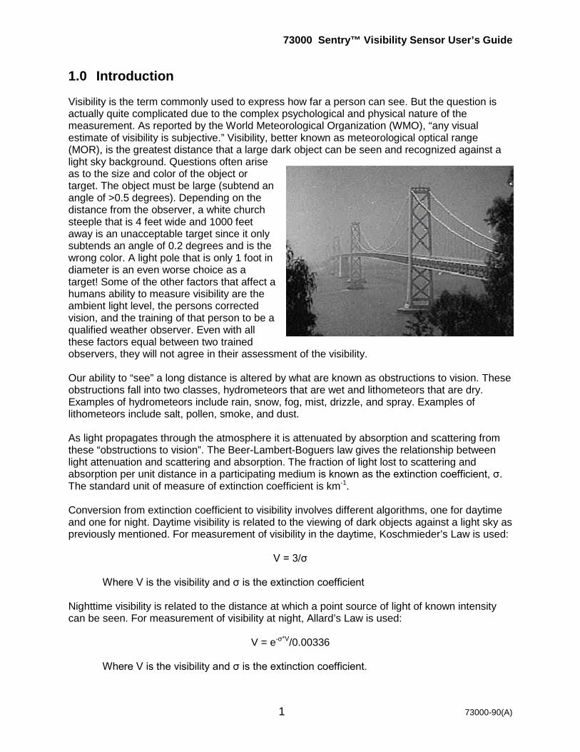
1.0 Introduction Visibility is the term commonly used to express how far a person can see. But the question is actually quite complicated due to the complex psychological and physical nature of the measurement. As reported by the World Meteorological Organization (WMO), “any visual estimate of visibility is subjective.” Visibility, better known as meteorological optical range (MOR), is the greatest distance that a large dark object can be seen and recognized against a light sky background. Questions often arise as to the size and color of the object or target. The object must be large (subtend an angle of >0.5 degrees). Depending on the distance from the observer, a white church steeple that is 4 feet wide and 1000 feet away is an unacceptable target since it only subtends an angle of 0.2 degrees and is the wrong color. A light pole that is only 1 foot in diameter is an even worse choice as a target! Some of the other factors that affect a humans ability to measure visibility are the ambient light level, the persons corrected vision, and the training of that person to be a qualified weather observer. Even with all these factors equal between two trained observers, they will not agree in their assessment of the visibility. Our ability to “see” a long distance is altered by what are known as obstructions to vision. These obstructions fall into two classes, hydrometeors that are wet and lithometeors that are dry. Examples of hydrometeors include rain, snow, fog, mist, drizzle, and spray. Examples of lithometeors include salt, pollen, smoke, and dust. As light propagates through the atmosphere it is attenuated by absorption and scattering from these “obstructions to vision”. The Beer-Lambert-Boguers law gives the relationship between light attenuation and scattering and absorption. The fraction of light lost to scattering and absorption per unit distance in a participating medium is known as the extinction coefficient, σ. The standard unit of measure of extinction coefficient is km-1. Conversion from extinction coefficient to visibility involves different algorithms, one for daytime and one for night. Daytime visibility is related to the viewing of dark objects against a light sky as previously mentioned. For measurement of visibility in the daytime, Koschmieder’s Law is used:
V = 3/σ
Where V is the visibility and σ is the extinction coefficient Nighttime visibility is related to the distance at which a point source of light of known intensity can be seen. For measurement of visibility at night, Allard’s Law is used:
V = e-σ*V/0.00336
Where V is the visibility and σ is the extinction coefficient.
73000 Sentry™ Visibility Sensor User’s Guide
2 73000-90(A)
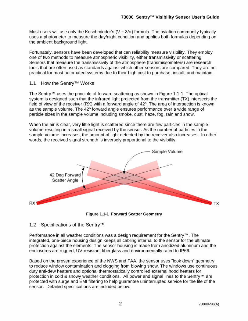
Most users will use only the Koschmieder’s (V = 3/σ) formula. The aviation community typically uses a photometer to measure the day/night condition and applies both formulas depending on the ambient background light. Fortunately, sensors have been developed that can reliability measure visibility. They employ one of two methods to measure atmospheric visibility, either transmissivity or scattering. Sensors that measure the transmissivity of the atmosphere (transmissometers) are research tools that are often used as standards against which other sensors are compared. They are not practical for most automated systems due to their high cost to purchase, install, and maintain. 1.1 How the Sentry™ Works The Sentry™ uses the principle of forward scattering as shown in Figure 1.1-1. The optical system is designed such that the infrared light projected from the transmitter (TX) intersects the field of view of the receiver (RX) with a forward angle of 42º. The area of intersection is known as the sample volume. The 42º forward angle ensures performance over a wide range of particle sizes in the sample volume including smoke, dust, haze, fog, rain and snow. When the air is clear, very little light is scattered since there are few particles in the sample volume resulting in a small signal received by the sensor. As the number of particles in the sample volume increases, the amount of light detected by the receiver also increases. In other words, the received signal strength is inversely proportional to the visibility.
Figure 1.1-1 Forward Scatter Geometry 1.2 Specifications of the Sentry™ Performance in all weather conditions was a design requirement for the Sentry™. The integrated, one-piece housing design keeps all cabling internal to the sensor for the ultimate protection against the elements. The sensor housing is made from anodized aluminum and the enclosures are rugged, UV-resistant fiberglass and environmentally rated to IP66. Based on the proven experience of the NWS and FAA, the sensor uses ”look down” geometry to reduce window contamination and clogging from blowing snow. The windows use continuous duty anti-dew heaters and optional thermostatically controlled external hood heaters for protection in cold & snowy weather conditions. All power and signal lines to the Sentry™ are protected with surge and EMI filtering to help guarantee uninterrupted service for the life of the sensor. Detailed specifications are included below:
73000 Sentry™ Visibility Sensor User’s Guide
3 73000-90(A)
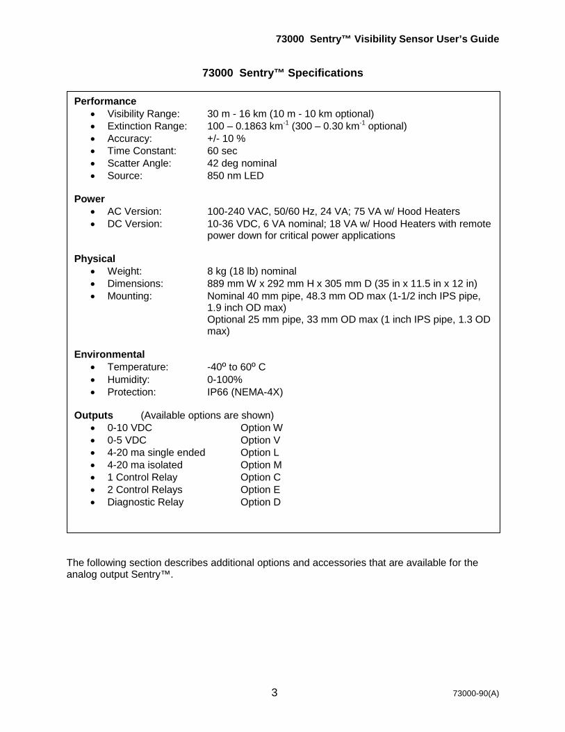
73000 Sentry™ Specifications
The following section describes additional options and accessories that are available for the analog output Sentry™.
Performance • Visibility Range: 30 m - 16 km (10 m - 10 km optional) • Extinction Range: 100 – 0.1863 km-1 (300 – 0.30 km-1 optional) • Accuracy: +/- 10 % • Time Constant: 60 sec • Scatter Angle: 42 deg nominal • Source: 850 nm LED
Power
• AC Version: 100-240 VAC, 50/60 Hz, 24 VA; 75 VA w/ Hood Heaters • DC Version: 10-36 VDC, 6 VA nominal; 18 VA w/ Hood Heaters with remote
power down for critical power applications Physical
• Weight: 8 kg (18 lb) nominal • Dimensions: 889 mm W x 292 mm H x 305 mm D (35 in x 11.5 in x 12 in) • Mounting: Nominal 40 mm pipe, 48.3 mm OD max (1-1/2 inch IPS pipe,
1.9 inch OD max) Optional 25 mm pipe, 33 mm OD max (1 inch IPS pipe, 1.3 OD max)
Environmental
• Temperature: -40º to 60º C • Humidity: 0-100% • Protection: IP66 (NEMA-4X)
Outputs (Available options are shown)
• 0-10 VDC Option W • 0-5 VDC Option V • 4-20 ma single ended Option L • 4-20 ma isolated Option M • 1 Control Relay Option C • 2 Control Relays Option E • Diagnostic Relay Option D

73000 Sentry™ Visibility Sensor User’s Guide
4 73000-90(A)
1.2.1 Description of Options & Accessories The model number of the Sentry™ is key to understanding what options are installed in each unit. The model number is found on the sensor label, shown in Figure 1.2.1-1, which is located on the outside of the Main Electronics Enclosure. The model number is composed of 2 parts. The 5 numeric characters indicate the model (example: 73000) followed by options characters which identify the specific option/s on the unit.
• “A” = mains voltage options • “W” = analog output options • “C” = control relay #1
Figure 1.2.1-1 Sensor Label
1.2.1.1 Power Supply Options The 1st option character group describes the mains voltage options on the Sentry™ as described in Table 1.2.1.1-1.
Table 1.2.1.1-1
When the 1st character
is… The Mains
Voltage is… Standard
or Optional?
Description Voltage Range Freq Nominal Power
w/o HTRS Power w/ HTRSNote1
A 100-240 VAC Standard 88-264 VAC 47-63 Hz 24 VA 75 VA D 12 VDC Optional 10-36 VDC --- 6 VA 18 VA
Note 1 – See Section 1.2.1.3 for information on the external hood heater (HTR) option.
73000 Sentry™ Visibility Sensor User’s Guide
5 73000-90(A)
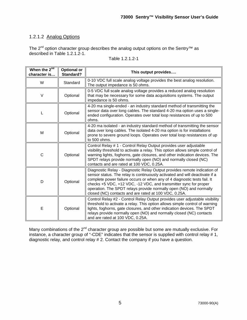
1.2.1.2 Analog Options The 2nd option character group describes the analog output options on the Sentry™ as described in Table 1.2.1.2-1.
Table 1.2.1.2-1
When the 2nd character is…
Optional or Standard? This output provides….
W Standard 0-10 VDC full scale analog voltage provides the best analog resolution. The output impedance is 50 ohms.
V Optional 0-5 VDC full scale analog voltage provides a reduced analog resolution that may be necessary for some data acquisitions systems. The output impedance is 50 ohms.
L Optional 4-20 ma single-ended - an industry standard method of transmitting the sensor data over long cables. The standard 4-20 ma option uses a single-ended configuration. Operates over total loop resistances of up to 500 ohms.
M Optional 4-20 ma isolated - an industry standard method of transmitting the sensor data over long cables. The isolated 4-20 ma option is for installations prone to severe ground loops. Operates over total loop resistances of up to 500 ohms.
C Optional
Control Relay # 1 - Control Relay Output provides user adjustable visibility threshold to activate a relay. This option allows simple control of warning lights, foghorns, gate closures, and other indication devices. The SPDT relays provide normally open (NO) and normally closed (NC) contacts and are rated at 100 VDC, 0.25A.
D Optional
Diagnostic Relay - Diagnostic Relay Output provides remote indication of sensor status. The relay is continuously activated and will deactivate if a complete power failure occurs or when any of 4 diagnostic tests fail. It checks +5 VDC, +12 VDC, -12 VDC, and transmitter sync for proper operation. The SPDT relays provide normally open (NO) and normally closed (NC) contacts and are rated at 100 VDC, 0.25A.
E Optional
Control Relay #2 - Control Relay Output provides user adjustable visibility threshold to activate a relay. This option allows simple control of warning lights, foghorns, gate closures, and other indication devices. The SPDT relays provide normally open (NO) and normally closed (NC) contacts and are rated at 100 VDC, 0.25A.
Many combinations of the 2nd character group are possible but some are mutually exclusive. For instance, a character group of “-CDE” indicates that the sensor is supplied with control relay # 1, diagnostic relay, and control relay # 2. Contact the company if you have a question.
73000 Sentry™ Visibility Sensor User’s Guide
6 73000-90(A)
1.2.1.3 Hood Heater (73004 only) Silicone resistance heaters are installed under each black metal hood that covers the front of the transmitter and receiver heads to prevent blowing snow from clogging the sensor’s optical path. Thermostatically controlled to automatically turn on at ~3º C and off at ~8º C. With AC powered sensors, each hood heater consumes 25 W of power from a 24 VAC transformer in the Sentry™ Electronics Enclosure. With 12 VDC powered sensors, each hood heater consumes 6 W of power from the 12 VDC input power.

73000 Sentry™ Visibility Sensor User’s Guide
7 73000-90(A)
1.2.1.4 Accessories Several accessories are available with the Sentry™ as described in Table 1.2.1.6-1.
Table 1.2.1.6-1
Part Number Accessory Name Description
73060 Calibration Fixture
Required for installation and maintenance of the sensor. Provides a traceable calibration of the sensor by scattering a known amount of light from the transmitter to the receiver. One Calibration Fixture can be used on several Sentry™ Visibility Sensors.
73038 Hood
Extension Set
The units slip over the existing sensor hoods to provide additional protection from heavily contaminated air found at some sites. Typical applications include:
• Road & bridge sites where sensor is <10m from the edge of the roadway
• Coastal & maritime areas subject to blowing salt spray
• Areas with heavy industrial pollution
Includes a set of 2 hood extensions that are easily installed and removable for sensor calibration with a screwdriver.
74050 Mounting Bracket
Used to mount the Sentry Visibility Sensor with standard 1-1/2” mounting flange. It is designed to provide a durable, vibration-free installation of the Sentry and can be installed against a flat wall, traffic & light poles, or typical ROHN-type tower leg.
74054 AC Power Cable
Optional North American style 3-conductor, #18 AWG, 3 meter, molded male plug, SJT type, UL & CSA rated, CEE color-codes. Power cables for international orders will be supplied with the appropriate molded plug.
74056 Signal Cable
Optional twisted shielded pair cable, 22 AWG, PVC jacket, where “xx” is the length in meters. Max 15 m (50 ft) recommended.
74055 DC Power Cable
Optional 2-conductor twisted shielded, 20 AWG, PVC jacket, where “xx” is the length in meters. Max 15 m (50 ft) recommended.
73000 Sentry™ Visibility Sensor User’s Guide
8 73000-90(A)
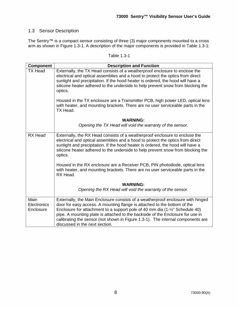
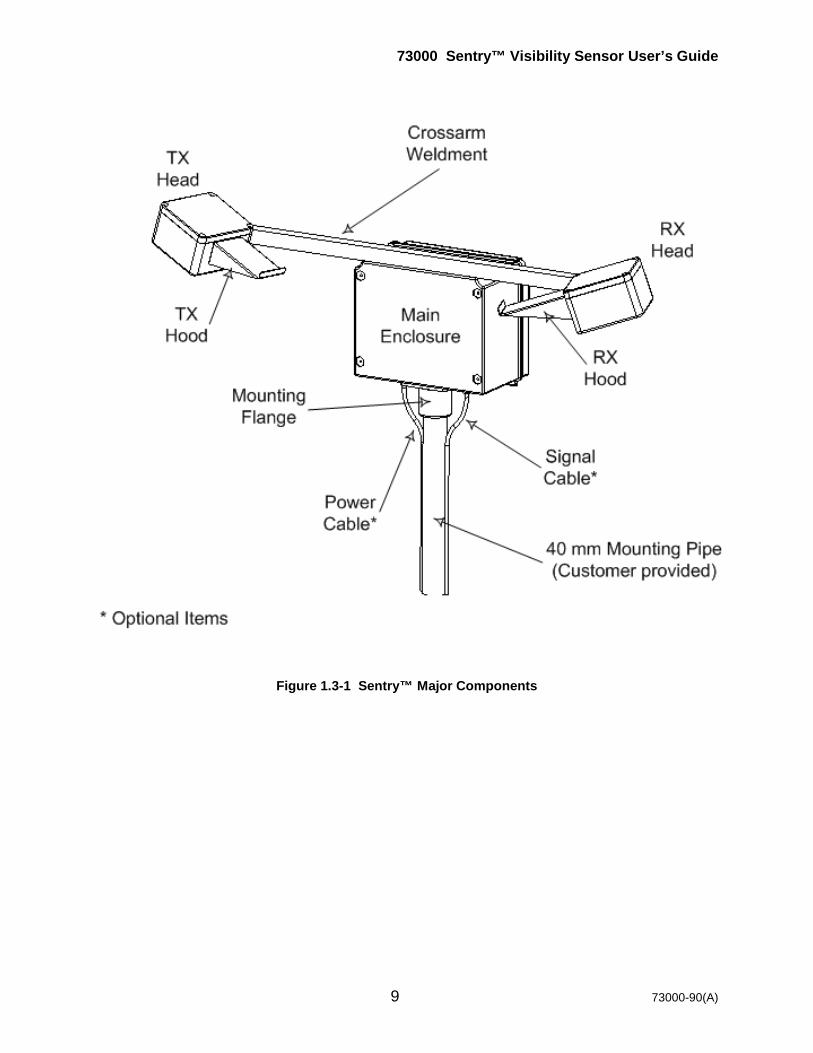
1.3 Sensor Description The Sentry™ is a compact sensor consisting of three (3) major components mounted to a cross arm as shown in Figure 1.3-1. A description of the major components is provided in Table 1.3-1: Table 1.3-1 Component Description and Function TX Head Externally, the TX Head consists of a weatherproof enclosure to enclose the
electrical and optical assemblies and a hood to protect the optics from direct sunlight and precipitation. If the hood heater is ordered, the hood will have a silicone heater adhered to the underside to help prevent snow from blocking the optics. Housed in the TX enclosure are a Transmitter PCB, high power LED, optical lens with heater, and mounting brackets. There are no user serviceable parts in the TX Head.
WARNING:
Opening the TX Head will void the warranty of the sensor.
RX Head Externally, the RX Head consists of a weatherproof enclosure to enclose the electrical and optical assemblies and a hood to protect the optics from direct sunlight and precipitation. If the hood heater is ordered, the hood will have a silicone heater adhered to the underside to help prevent snow from blocking the optics. Housed in the RX enclosure are a Receiver PCB, PIN photodiode, optical lens with heater, and mounting brackets. There are no user serviceable parts in the RX Head.
WARNING:
Opening the RX Head will void the warranty of the sensor.
Main Electronics Enclosure
Externally, the Main Enclosure consists of a weatherproof enclosure with hinged door for easy access. A mounting flange is attached to the bottom of the Enclosure for attachment to a support pole of 40 mm dia (1-½” Schedule 40) pipe. A mounting plate is attached to the backside of the Enclosure for use in calibrating the sensor (not shown in Figure 1.3-1). The internal components are discussed in the next section.
73000 Sentry™ Visibility Sensor User’s Guide
9 73000-90(A)
Figure 1.3-1 Sentry™ Major Components
73000 Sentry™ Visibility Sensor User’s Guide
10 73000-90(A)
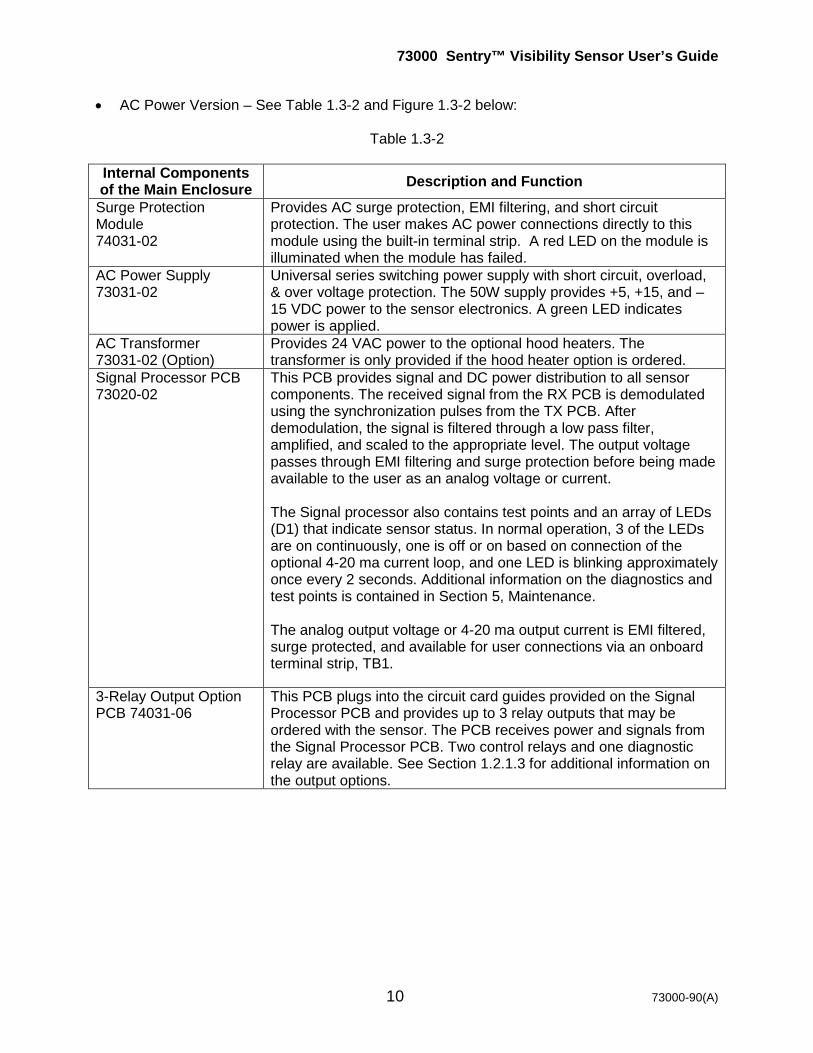
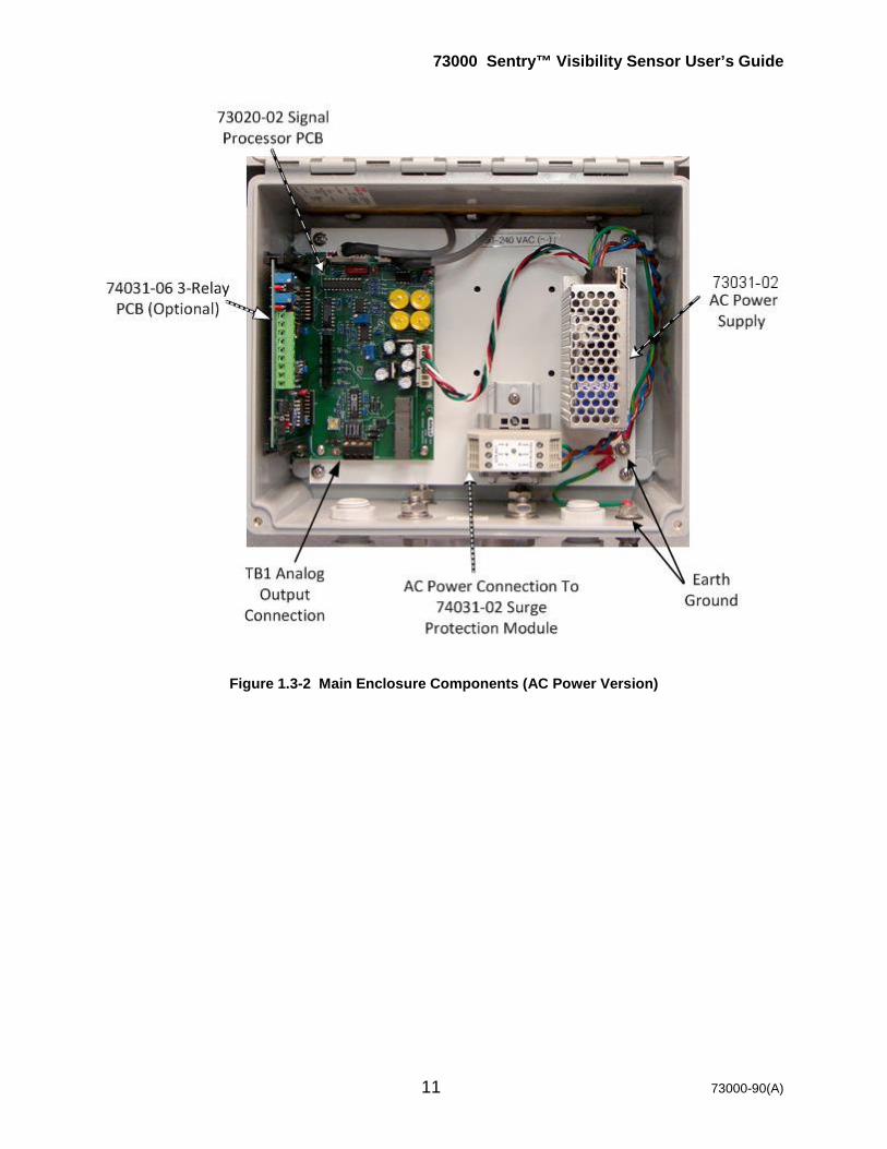
• AC Power Version – See Table 1.3-2 and Figure 1.3-2 below:
Table 1.3-2 Internal Components of the Main Enclosure Description and Function
Surge Protection Module 74031-02
Provides AC surge protection, EMI filtering, and short circuit protection. The user makes AC power connections directly to this module using the built-in terminal strip. A red LED on the module is illuminated when the module has failed.
AC Power Supply 73031-02
Universal series switching power supply with short circuit, overload, & over voltage protection. The 50W supply provides +5, +15, and –15 VDC power to the sensor electronics. A green LED indicates power is applied.
AC Transformer 73031-02 (Option)
Provides 24 VAC power to the optional hood heaters. The transformer is only provided if the hood heater option is ordered.
Signal Processor PCB 73020-02
This PCB provides signal and DC power distribution to all sensor components. The received signal from the RX PCB is demodulated using the synchronization pulses from the TX PCB. After demodulation, the signal is filtered through a low pass filter, amplified, and scaled to the appropriate level. The output voltage passes through EMI filtering and surge protection before being made available to the user as an analog voltage or current. The Signal processor also contains test points and an array of LEDs (D1) that indicate sensor status. In normal operation, 3 of the LEDs are on continuously, one is off or on based on connection of the optional 4-20 ma current loop, and one LED is blinking approximately once every 2 seconds. Additional information on the diagnostics and test points is contained in Section 5, Maintenance. The analog output voltage or 4-20 ma output current is EMI filtered, surge protected, and available for user connections via an onboard terminal strip, TB1.
3-Relay Output Option PCB 74031-06
This PCB plugs into the circuit card guides provided on the Signal Processor PCB and provides up to 3 relay outputs that may be ordered with the sensor. The PCB receives power and signals from the Signal Processor PCB. Two control relays and one diagnostic relay are available. See Section 1.2.1.3 for additional information on the output options.
73000 Sentry™ Visibility Sensor User’s Guide
11 73000-90(A)
Figure 1.3-2 Main Enclosure Components (AC Power Version)

73000 Sentry™ Visibility Sensor User’s Guide
12 73000-90(A)
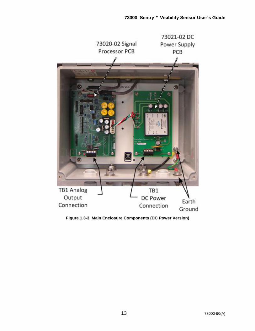
• DC Power Version – See Table 1.3-3 and Figure 1.3-3 below:
Table 1.3-3 Internal Components of the Main Enclosure Description and Function
DC Power Supply 73021-02
The DC/DC Converter Module provides +5, +15, and –15 VDC power to the sensor electronics. Also provides DC surge protection, EMI filtering, and short circuit protection via resettable fuses. The user makes DC power connections directly to this PCB using the built-in terminal board, TB1. The user connects a regulated DC voltage between 10-36 VDC capable of supplying 1A. An added feature is the ability to remotely turn power OFF to the Sentry to reduce power consumption. By connecting a ground to terminal 3 of TB1 on the DC power PCB, the DC/DC converter is put into the sleep mode until the ground is released. This may be controlled by a standard TTL line or I/O port. Additional information is contained in Section 2.4.2.
Signal Processor PCB 73020-02
This PCB provides signal and DC power distribution to all sensor components. The received signal from the RX PCB is demodulated using the synchronization pulses from the TX PCB. After demodulation, the signal is filtered through a low pass filter, amplified, and scaled to the appropriate level. The output voltage passes through EMI filtering and surge protection before being made available to the user as an analog voltage. The Signal processor also contains test points and an array of LEDs (D1) that indicate sensor status. In normal operation, 3 of the LEDs are on continuously, one is off or on based on connection of the optional 4-20 ma current loop, and one LED is blinking approximately once every 2 seconds. Additional information on the diagnostics and test points is contained in Section 5, Maintenance. The analog output voltage or 4-20 ma output current is EMI filtered, surge protected, and available for user connections via an onboard terminal strip, TB1.
3-Relay Output Option PCB 74031-06
This PCB plugs into the circuit card guides provided on the Signal Processor PCB and provides up to 3 relay outputs that may be ordered with the sensor. The PCB receives power and signals from the Signal Processor PCB. Two control relays and one diagnostic relay are available. See Section 1.2.1.3 for additional information on the output options.
73000 Sentry™ Visibility Sensor User’s Guide
13 73000-90(A)
Figure 1.3-3 Main Enclosure Components (DC Power Version)
73000 Sentry™ Visibility Sensor User’s Guide
14 73000-90(A)
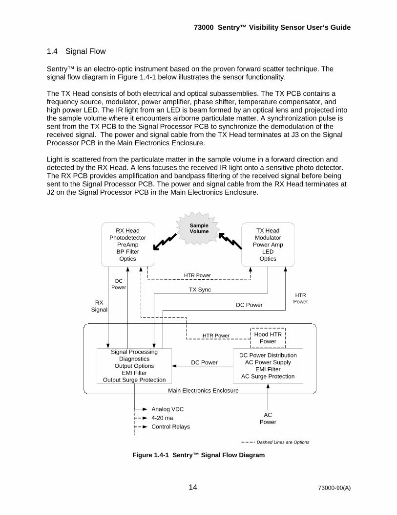
1.4 Signal Flow Sentry™ is an electro-optic instrument based on the proven forward scatter technique. The signal flow diagram in Figure 1.4-1 below illustrates the sensor functionality. The TX Head consists of both electrical and optical subassemblies. The TX PCB contains a frequency source, modulator, power amplifier, phase shifter, temperature compensator, and high power LED. The IR light from an LED is beam formed by an optical lens and projected into the sample volume where it encounters airborne particulate matter. A synchronization pulse is sent from the TX PCB to the Signal Processor PCB to synchronize the demodulation of the received signal. The power and signal cable from the TX Head terminates at J3 on the Signal Processor PCB in the Main Electronics Enclosure. Light is scattered from the particulate matter in the sample volume in a forward direction and detected by the RX Head. A lens focuses the received IR light onto a sensitive photo detector. The RX PCB provides amplification and bandpass filtering of the received signal before being sent to the Signal Processor PCB. The power and signal cable from the RX Head terminates at J2 on the Signal Processor PCB in the Main Electronics Enclosure.
Figure 1.4-1 Sentry™ Signal Flow Diagram
Sample Volume RX Head
Photodetector PreAmp BP Filter Optics
TX Head Modulator
Power Amp LED
Optics
Signal Processing Diagnostics
Output Options EMI Filter
Output Surge Protection
DC Power Distribution AC Power Supply
EMI Filter AC Surge Protection
AC Power
Analog VDC 4-20 ma Control Relays
DC Power
DC Power
DC Power
RX Signal
TX Sync
Hood HTR Power
Dashed Lines are Options
Main Electronics Enclosure
HTR Power
HTR Power
HTR Power
73000 Sentry™ Visibility Sensor User’s Guide
15 73000-90(A)
2.0 Installation 2.1 Site Preparation Site selection and preparation are critical for the successful performance of the Sentry™ Visibility Sensor. If a good location for the sensor is not chosen the sensor is not installed correctly, it will not measure data that is representative of the visibility in the area. We will be glad to help you with your installation. Call or email any questions & send pictures of proposed locations to discuss your particular application!
2.1.1 Siting Guidelines General guidelines for all users:
• Use a sturdy pole or pedestal to reduce vibration. • Locate the sensor in an area that is representative of the area to be monitored. • Do not locate the sensor near strobe lights and other modulated
light sources. • Do not locate the sensor in an area that is subject to localized
sources of smoke, fog, or mist (air handling exhausts, smoke stacks, etc) unless you are trying to measure the reduction in visibility from these sources.
• The area within 5-6 meters (16-20 feet) of the sensor should be free of all vegetation over 25 cm (10 inch) and well drained.
• Avoid any vertical objects such as hills, walls, or plants within this area.
o If in path of the TX beam, light may be reflected back into the receiver giving false readings.
o If in path of RX beam, stray sunlight may be reflected back into the receiver giving false readings
• Mount the sensor so the optics are at least 2.5-3 meters (8-10 feet) above ground or 2.5 meters (8 feet) above the average maximum snow depth, whichever is higher.
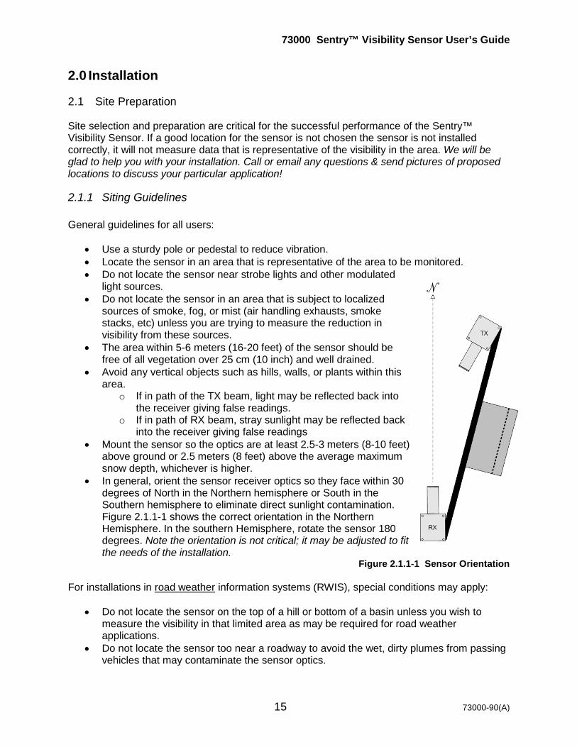
• In general, orient the sensor receiver optics so they face within 30 degrees of North in the Northern hemisphere or South in the Southern hemisphere to eliminate direct sunlight contamination. Figure 2.1.1-1 shows the correct orientation in the Northern Hemisphere. In the southern Hemisphere, rotate the sensor 180 degrees. Note the orientation is not critical; it may be adjusted to fit the needs of the installation.
Figure 2.1.1-1 Sensor Orientation For installations in road weather information systems (RWIS), special conditions may apply:
• Do not locate the sensor on the top of a hill or bottom of a basin unless you wish to measure the visibility in that limited area as may be required for road weather applications.
• Do not locate the sensor too near a roadway to avoid the wet, dirty plumes from passing vehicles that may contaminate the sensor optics.

73000 Sentry™ Visibility Sensor User’s Guide
16 73000-90(A)
• If the installation must be near the edge of the road it may be best to orient the sensor parallel to the road with the Main Electronics Enclosure facing the roadway as shown in Figure 2.1.1-2.
• The Federal Highway Administration (FHWA) has established standards for RWIS systems siting. Contact FHWA and request Publication No. FHWA-HOP-05-206 or visit http://ops.fhwa.dot.gov/publications/ess05/index.htm.
• The World Meteorological Organization (WMO) has published Report No. 61 - Road Meteorological Observations that also recommends sensor siting. Contact the WMO and request TD 842 (IOM 61) or http://www.wmo.int/pages/prog/www/IMOP/publications-IOM-series.html.
Figure 2.1.1-2 Typical Roadside Installation For installations in road or rail tunnels, the Tunnel Guidelines document may be requested by sending an E-Mail to: [email protected] It contains information on visibility sensor siting recommendations within the tunnel, specifics about installing the Sentry™, and guidance information about how several agencies around the world are using the data from tunnel mounted visibility sensors. A typical tunnel installation is shown in Figure 2.1.1-3.
Figure 2.1.1-3 Typical Tunnel Installation For installations on offshore platforms, the EEx Sentry Siting document may be requested by sending an E-Mail to: [email protected]. It contains specific information for siting & installing the Sentry™ on offshore platforms to ensure proper operation in that critical environment. For installations at airports the user is encouraged to contact the appropriate regulating agencie(s) to ensure compliance with aviation requirements:
• U.S.A. – Office of the Federal Coordinator for Meteorology at 301.427.2002 (Silver Spring, Maryland) for a copy of “Federal Standard for Siting Meteorological Sensors at Airports, OFCM, FCM-S4-1994” and other related documents. or visit http://www.ofcm.gov/siting/text/a-cover.htm.
73000 Sentry™ Visibility Sensor User’s Guide
17 73000-90(A)
• International – International Civil Aviation Organization at 514.954.8022 (Montreal, Quebec Canada) for a copy of “Manual of Aeronautical Meteorological Practice” and other related documents. Or visit http://www.icao.int/icao/en/sales.htm.
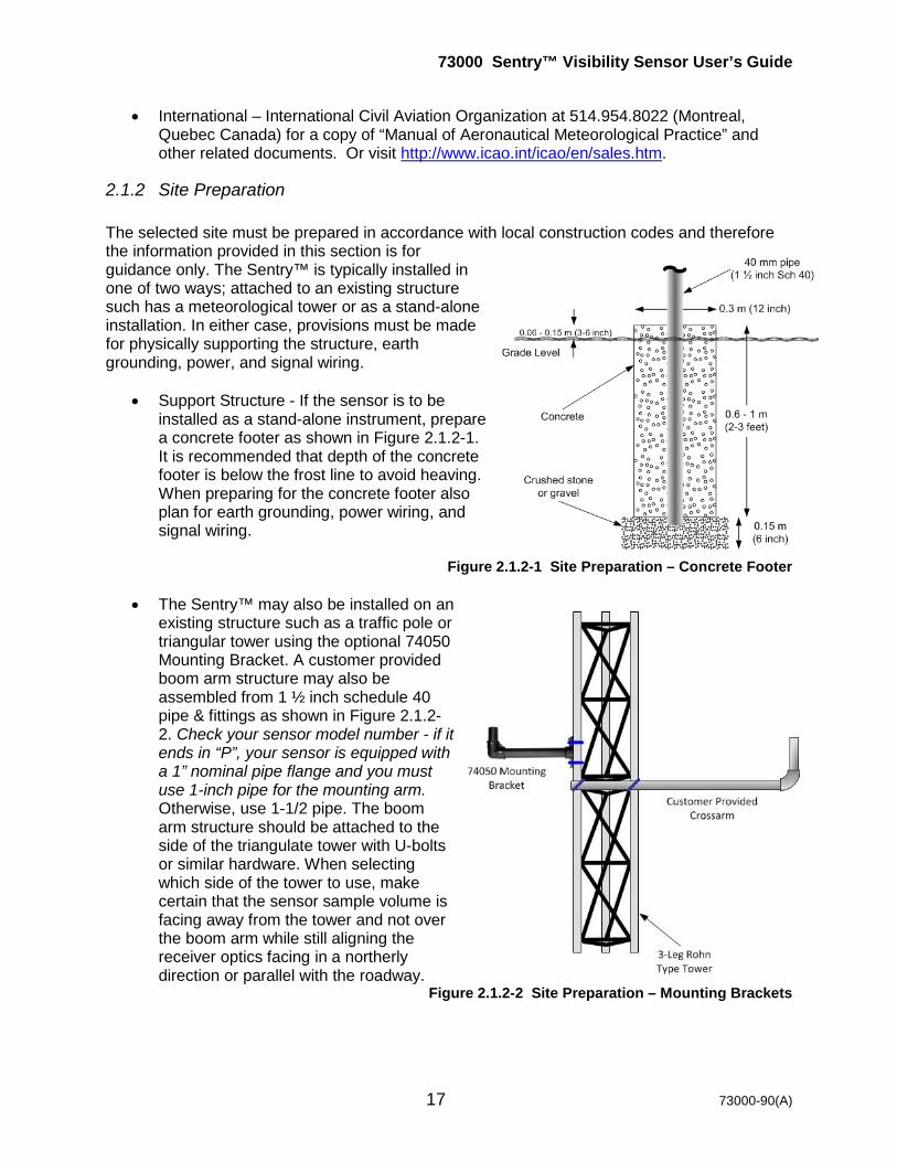
2.1.2 Site Preparation The selected site must be prepared in accordance with local construction codes and therefore the information provided in this section is for guidance only. The Sentry™ is typically installed in one of two ways; attached to an existing structure such has a meteorological tower or as a stand-alone installation. In either case, provisions must be made for physically supporting the structure, earth grounding, power, and signal wiring.
• Support Structure - If the sensor is to be installed as a stand-alone instrument, prepare a concrete footer as shown in Figure 2.1.2-1. It is recommended that depth of the concrete footer is below the frost line to avoid heaving. When preparing for the concrete footer also plan for earth grounding, power wiring, and signal wiring.
Figure 2.1.2-1 Site Preparation – Concrete Footer
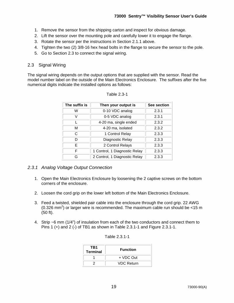
• The Sentry™ may also be installed on an
existing structure such as a traffic pole or triangular tower using the optional 74050 Mounting Bracket. A customer provided boom arm structure may also be assembled from 1 ½ inch schedule 40 pipe & fittings as shown in Figure 2.1.2-2. Check your sensor model number - if it ends in “P”, your sensor is equipped with a 1” nominal pipe flange and you must use 1-inch pipe for the mounting arm. Otherwise, use 1-1/2 pipe. The boom arm structure should be attached to the side of the triangulate tower with U-bolts or similar hardware. When selecting which side of the tower to use, make certain that the sensor sample volume is facing away from the tower and not over the boom arm while still aligning the receiver optics facing in a northerly direction or parallel with the roadway.
Figure 2.1.2-2 Site Preparation – Mounting Brackets

73000 Sentry™ Visibility Sensor User’s Guide
18 73000-90(A)
• Earth Grounding – The Sentry™ must be grounded to an approved earth terminal for electrical safety and for the built-in lightning protection circuitry to work properly. This wiring is in addition to the “ground” wire that is part of the AC power wiring. Additional information on earth grounding is found in Section 2.3.3.
• Power – The Sentry™ requires a source of single phase AC power (unless the 12 VDC
option was ordered) at 1 A current. Consideration should be made to add power and signal junction boxes near the sensor during the construction phase. Additional information on AC wiring is found in Section 2.3.1.
• Signal Wiring – The rule of thumb is that the shorter the signal wire, the better. R.M.
Young Company recommends that signal wires be <15 m (<50 ft) and 22 AWG (0.326 mm2) or larger wire gauge. Exceptions to this rule are made for the optional 4-20 ma current loop output option and the control relay option where the cable may be much longer.
2.2 Mechanical Installation Once the site preparation is complete, physically installing the Sentry™ is simple. Follow these steps to complete the mechanical installation as shown in Figure 2.2-1. When unpacking the sensor, carefully remove the packing material and lift the sensor out of the shipping carton. If the sensor must be laid down, lay it flat with the front door of the Main Electronics Enclosure down to avoid any damage to the sensor heads or hoods. Equipment required:
• 9/16” wrench, 9/16” nut driver, or adjustable wrench
Figure 2.2-1 Mechanical Installation
73000 Sentry™ Visibility Sensor User’s Guide
19 73000-90(A)
1. Remove the sensor from the shipping carton and inspect for obvious damage. 2. Lift the sensor over the mounting pole and carefully lower it to engage the flange. 3. Rotate the sensor per the instructions in Section 2.1.1 above. 4. Tighten the two (2) 3/8-16 hex head bolts in the flange to secure the sensor to the pole. 5. Go to Section 2.3 to connect the signal wiring.
2.3 Signal Wiring The signal wiring depends on the output options that are supplied with the sensor. Read the model number label on the outside of the Main Electronics Enclosure. The suffixes after the five numerical digits indicate the installed options as follows:
Table 2.3-1
The suffix is Then your output is See section W 0-10 VDC analog 2.3.1 V 0-5 VDC analog 2.3.1 L 4-20 ma, single ended 2.3.2 M 4-20 ma, isolated 2.3.2 C 1 Control Relay 2.3.3 D Diagnostic Relay 2.3.3 E 2 Control Relays 2.3.3 F 1 Control, 1 Diagnostic Relay 2.3.3 G 2 Control, 1 Diagnostic Relay 2.3.3
2.3.1 Analog Voltage Output Connection
1. Open the Main Electronics Enclosure by loosening the 2 captive screws on the bottom corners of the enclosure.
2. Loosen the cord grip on the lower left bottom of the Main Electronics Enclosure.
3. Feed a twisted, shielded pair cable into the enclosure through the cord grip. 22 AWG
(0.326 mm2) or larger wire is recommended. The maximum cable run should be <15 m (50 ft).
4. Strip ~6 mm (1/4”) of insulation from each of the two conductors and connect them to
Pins 1 (+) and 2 (-) of TB1 as shown in Table 2.3.1-1 and Figure 2.3.1-1.
Table 2.3.1-1
TB1 Terminal Function
1 + VDC Out 2 VDC Return
73000 Sentry™ Visibility Sensor User’s Guide
20 73000-90(A)
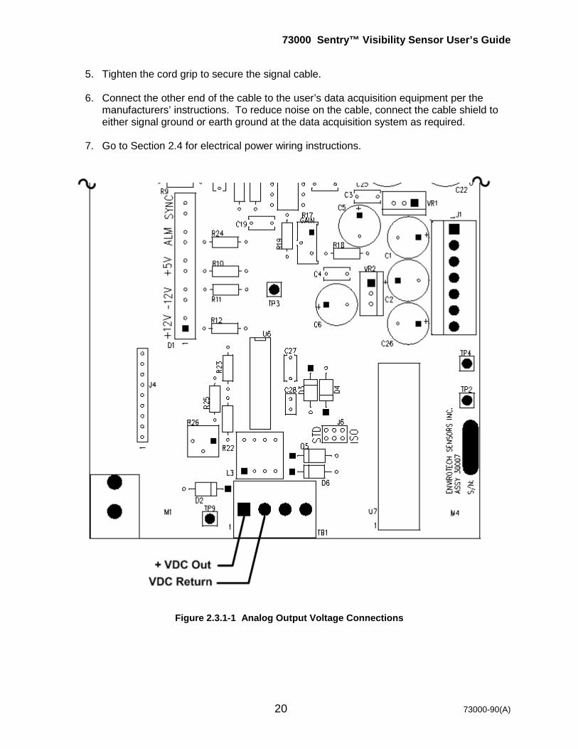
5. Tighten the cord grip to secure the signal cable.
6. Connect the other end of the cable to the user’s data acquisition equipment per the manufacturers’ instructions. To reduce noise on the cable, connect the cable shield to either signal ground or earth ground at the data acquisition system as required.
7. Go to Section 2.4 for electrical power wiring instructions.
Figure 2.3.1-1 Analog Output Voltage Connections
73000 Sentry™ Visibility Sensor User’s Guide
21 73000-90(A)
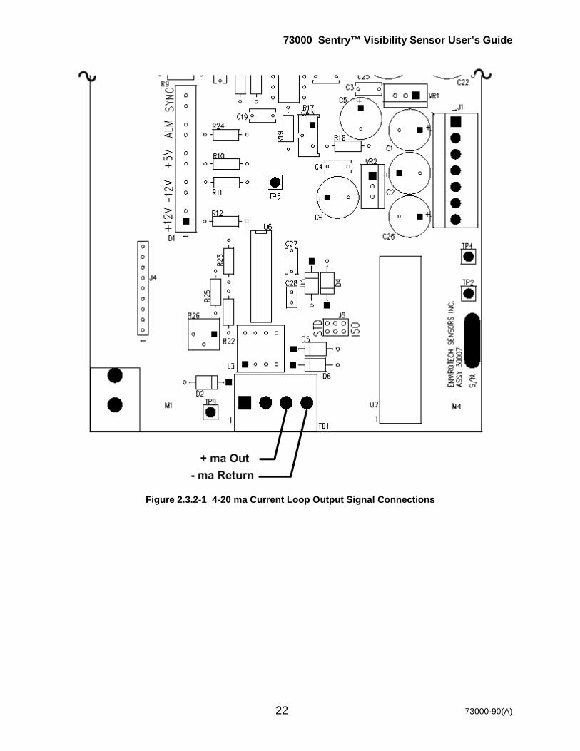
2.3.2 4-20 ma Current Loop Output Connection The Sentry™ 4-20 ma output options are part of the Signal Processor PCB in the Main Electronics Enclosure. The PCB is factory configured for either single-ended (-A) or isolated (-B) 4-20 ma depending on the option ordered. User connections are made to TB1 of the Signal Processor PCB.
1. Loosen the cord grip on the lower left bottom of the Main Electronics Enclosure.
2. Feed a twisted, shielded pair cable into the enclosure through the cord grip. 22 AWG (0.326 mm2) or larger wire is recommended. The cable run may be as long as necessary provided the total resistance of the entire loop including outgoing wire, customer data acquisition system resistance, and return wire is < 500 ohms.
3. Strip ~6 mm (1/4”) of insulation from each of the two conductors and connect them to
TB1 using the information in Table 2.3.2-1 and Figure 2.3.2-1.
Table 2.3.2-1
TB1 Terminal Function
3 + ma Out 4 - ma Return
4. Tighten the cord grip to secure the signal cable.
5. Connect the other end of the cable to the users’ data acquisition equipment per the
manufacturers’ instructions. To reduce noise on the cable, connect the cable shield to either signal ground or earth ground at the data acquisition system as required.
6. Go to Section 2.4 for electrical power wiring instructions.
73000 Sentry™ Visibility Sensor User’s Guide
22 73000-90(A)
Figure 2.3.2-1 4-20 ma Current Loop Output Signal Connections
73000 Sentry™ Visibility Sensor User’s Guide
23 73000-90(A)
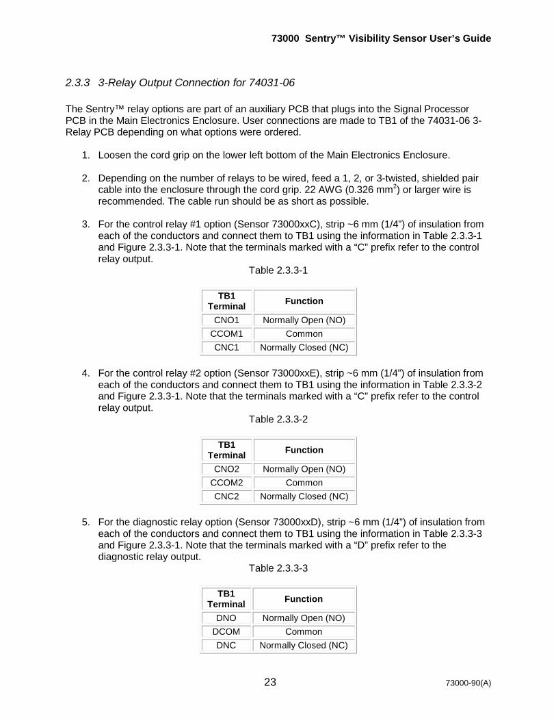
2.3.3 3-Relay Output Connection for 74031-06 The Sentry™ relay options are part of an auxiliary PCB that plugs into the Signal Processor PCB in the Main Electronics Enclosure. User connections are made to TB1 of the 74031-06 3-Relay PCB depending on what options were ordered.
1. Loosen the cord grip on the lower left bottom of the Main Electronics Enclosure.
2. Depending on the number of relays to be wired, feed a 1, 2, or 3-twisted, shielded pair cable into the enclosure through the cord grip. 22 AWG (0.326 mm2) or larger wire is recommended. The cable run should be as short as possible.
3. For the control relay #1 option (Sensor 73000xxC), strip ~6 mm (1/4”) of insulation from
each of the conductors and connect them to TB1 using the information in Table 2.3.3-1 and Figure 2.3.3-1. Note that the terminals marked with a “C” prefix refer to the control relay output.
Table 2.3.3-1
TB1 Terminal Function
CNO1 Normally Open (NO) CCOM1 Common CNC1 Normally Closed (NC)
4. For the control relay #2 option (Sensor 73000xxE), strip ~6 mm (1/4”) of insulation from
each of the conductors and connect them to TB1 using the information in Table 2.3.3-2 and Figure 2.3.3-1. Note that the terminals marked with a “C” prefix refer to the control relay output.
Table 2.3.3-2
TB1 Terminal Function
CNO2 Normally Open (NO) CCOM2 Common CNC2 Normally Closed (NC)
5. For the diagnostic relay option (Sensor 73000xxD), strip ~6 mm (1/4”) of insulation from
each of the conductors and connect them to TB1 using the information in Table 2.3.3-3 and Figure 2.3.3-1. Note that the terminals marked with a “D” prefix refer to the diagnostic relay output.
Table 2.3.3-3
TB1 Terminal Function
DNO Normally Open (NO) DCOM Common DNC Normally Closed (NC)
73000 Sentry™ Visibility Sensor User’s Guide
24 73000-90(A)
6. Tighten the cord grip to secure the signal cable.
7. Connect the other end of the cable to the users data acquisition equipment per the manufacturers instructions. To reduce noise on the cable, connect the cable shield to either signal ground or earth ground at the data acquisition system.
8. Go to Section 2.4 for electrical power wiring instructions.
Figure 2.3.3-1 3-Relay Output Signal Connections

73000 Sentry™ Visibility Sensor User’s Guide
25 73000-90(A)
2.4 Electrical Power Installation The most important step in connecting power to the Sentry™ is to make sure only authorized personnel make the AC connections. Read the information in Section 2 of this User’s Guide completely before proceeding. Remember that local electrical codes supersede the recommendations provided herein. If you have a question, call R.M. Young Company at 231-946-3980. The second step in connecting power to the Sentry™ is to make sure the correct mains voltage is used. Read the product label on the outside of the Main Electronics Enclosure door and compare the part number in Table 2.4-1 as follows:
Table 2.4-1
If your is Then your mains is See section 73000A 110-240 VAC, 50/60 Hz 2.4.1 73000D 10-36 VDC 2.4.2
For protection from lightning and other electrical surges, the sensor should be grounded to a rod driven into the ground adjacent to the sensor per Section 2.4.3. Equipment required:
• ¼ inch straight blade screwdriver • Small screwdriver • Wire cutters • Wire strippers • Adjustable wrench • 7/16 inch wrench, 7/16 inch nut driver, or adjustable wrench
2.4.1 AC Power Connections
1. Select an approved AC power cord with 3-wires that includes a ground and wire gauge of 18 AWG (0.902 mm-2) or larger wire is recommended. The cable run should be as short as possible.
2. Loosen the cord grip on the lower right bottom of the Main Electronics Enclosure.
3. Feed the power cable into the enclosure through the cord grip. Strip ~6 mm (1/4”) of
insulation from each of the three conductors and connect them to the line (left) side of the Surge Protection Module as shown per Table 2.4.1-1 and in Figure 2.4.1-1.

73000 Sentry™ Visibility Sensor User’s Guide
26 73000-90(A)
Table 2.4.1-1
International (ICC) Colors
North American (NA) Colors
Surge Module Terminal
Green/Yellow Green E (earth ground) Blue White N (neutral)
Brown Black L (line)
Figure 2.4.1-1 User AC Power Wiring 4. Tighten the cord grip to secure the power cord.
5. Go to Section 2.4.3 for earth grounding the Sentry™.
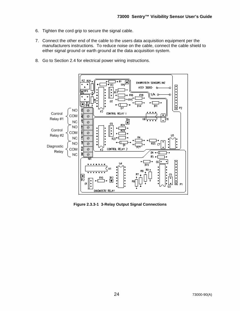
2.4.2 DC Power Connections (Optional)
1. A regulated DC power supply with a rating of 1 A minimum is recommended to power the Sentry™. A properly sized battery backed solar powered system may also be used.
2. Loosen the cord grip on the lower right bottom of the Main Electronics Enclosure.
3. Feed a 2 or 3-conductor power cable into the enclosure through the cord grip. 18 AWG
(0.823 mm2) or larger wire is recommended.
4. Strip ~6 mm (1/4”) of insulation from each of the conductors and connect them to TB1 of the 73021-02 DC Power PCB Assy as shown per Table 2.4.2-1 and in Figure 2.4.2-1.
5. If the ability to remotely control Sentry™ power is required, connect a wire to terminal 3
of TB1 on the DC Power Assy PCB. Connect the other end to a TTL line or I/O port that can be controlled by the user data acquisition system.
Remote Control Logic
Remote Control Line
Status Sentry™ Power Status
>2.5 VDC (TTL High) ON <0.8 VDC (TTL Low) OFF
73000 Sentry™ Visibility Sensor User’s Guide
27 73000-90(A)
6. Tighten the cord grip to secure the power cord. 7. Go to Section 2.4.3 for earth grounding the Sentry™.
Table 2.4.2-1
TB1 DC Power Version User Wire Color 1 +10-36 VDC 2 VDC Common 3 Remote Power Shutoff 4 Earth Ground GR/YL to Ground Stud
Figure 2.4.2-1 User DC Power Wiring
73000 Sentry™ Visibility Sensor User’s Guide
28 73000-90(A)
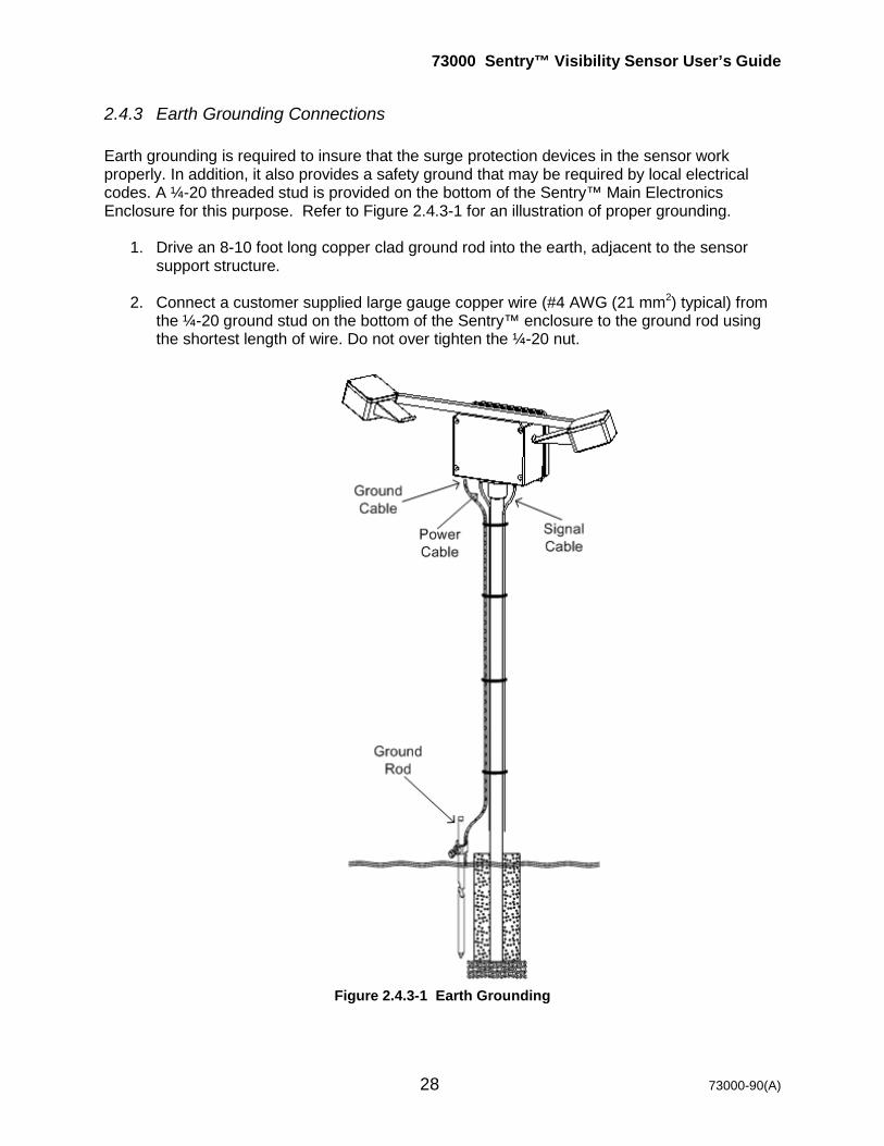
2.4.3 Earth Grounding Connections Earth grounding is required to insure that the surge protection devices in the sensor work properly. In addition, it also provides a safety ground that may be required by local electrical codes. A ¼-20 threaded stud is provided on the bottom of the Sentry™ Main Electronics Enclosure for this purpose. Refer to Figure 2.4.3-1 for an illustration of proper grounding.
1. Drive an 8-10 foot long copper clad ground rod into the earth, adjacent to the sensor
support structure.
2. Connect a customer supplied large gauge copper wire (#4 AWG (21 mm2) typical) from the ¼-20 ground stud on the bottom of the Sentry™ enclosure to the ground rod using the shortest length of wire. Do not over tighten the ¼-20 nut.
Figure 2.4.3-1 Earth Grounding
73000 Sentry™ Visibility Sensor User’s Guide
29 73000-90(A)
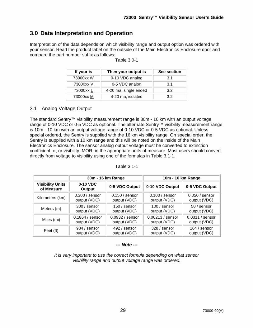
3.0 Data Interpretation and Operation Interpretation of the data depends on which visibility range and output option was ordered with your sensor. Read the product label on the outside of the Main Electronics Enclosure door and compare the part number suffix as follows:
Table 3.0-1
If your is Then your output is See section 73000xx W 0-10 VDC analog 3.1 73000xx V 0-5 VDC analog 3.1 73000xx L 4-20 ma, single ended 3.2 73000xx M 4-20 ma, isolated 3.2
3.1 Analog Voltage Output The standard Sentry™ visibility measurement range is 30m - 16 km with an output voltage range of 0-10 VDC or 0-5 VDC as optional. The alternate Sentry™ visibility measurement range is 10m - 10 km with an output voltage range of 0-10 VDC or 0-5 VDC as optional. Unless special ordered, the Sentry is supplied with the 16 km visibility range. On special order, the Sentry is supplied with a 10 km range and this will be noted on the inside of the Main Electronics Enclosure. The sensor analog output voltage must be converted to extinction coefficient, σ, or visibility, MOR, in the appropriate units of measure. Most users should convert directly from voltage to visibility using one of the formulas in Table 3.1-1.
Table 3.1-1
30m - 16 km Range 10m - 10 km Range Visibility Units
of Measure 0-10 VDC Output 0-5 VDC Output 0-10 VDC Output 0-5 VDC Output
Kilometers (km) 0.300 / sensor output (VDC)
0.150 / sensor output (VDC)
0.100 / sensor output (VDC)
0.050 / sensor output (VDC)
Meters (m) 300 / sensor output (VDC)
150 / sensor output (VDC)
100 / sensor output (VDC)
50 / sensor output (VDC)
Miles (mi) 0.1864 / sensor output (VDC)
0.0932 / sensor output (VDC)
0.06213 / sensor output (VDC)
0.0311 / sensor output (VDC)
Feet (ft) 984 / sensor output (VDC)
492 / sensor output (VDC)
328 / sensor output (VDC)
164 / sensor output (VDC)
--- Note ---
It is very important to use the correct formula depending on what sensor
visibility range and output voltage range was ordered.
73000 Sentry™ Visibility Sensor User’s Guide
30 73000-90(A)
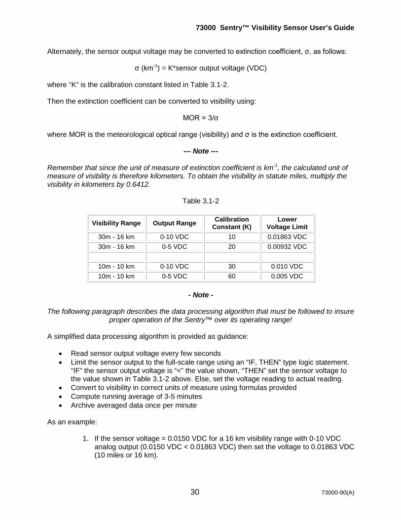
Alternately, the sensor output voltage may be converted to extinction coefficient, σ, as follows:
σ (km-1) = K*sensor output voltage (VDC) where “K” is the calibration constant listed in Table 3.1-2. Then the extinction coefficient can be converted to visibility using:
MOR = 3/σ where MOR is the meteorological optical range (visibility) and σ is the extinction coefficient.
--- Note --- Remember that since the unit of measure of extinction coefficient is km-1, the calculated unit of measure of visibility is therefore kilometers. To obtain the visibility in statute miles, multiply the visibility in kilometers by 0.6412.
Table 3.1-2
Visibility Range Output Range Calibration Constant (K)
Lower Voltage Limit
30m - 16 km 0-10 VDC 10 0.01863 VDC 30m - 16 km 0-5 VDC 20 0.00932 VDC
10m - 10 km 0-10 VDC 30 0.010 VDC 10m - 10 km 0-5 VDC 60 0.005 VDC
- Note -
The following paragraph describes the data processing algorithm that must be followed to insure
proper operation of the Sentry™ over its operating range! A simplified data processing algorithm is provided as guidance:
• Read sensor output voltage every few seconds • Limit the sensor output to the full-scale range using an “IF, THEN” type logic statement.
“IF” the sensor output voltage is “<” the value shown, “THEN” set the sensor voltage to the value shown in Table 3.1-2 above. Else, set the voltage reading to actual reading.
• Convert to visibility in correct units of measure using formulas provided • Compute running average of 3-5 minutes • Archive averaged data once per minute
As an example:
1. If the sensor voltage = 0.0150 VDC for a 16 km visibility range with 0-10 VDC analog output (0.0150 VDC < 0.01863 VDC) then set the voltage to 0.01863 VDC (10 miles or 16 km).

73000 Sentry™ Visibility Sensor User’s Guide
31 73000-90(A)
2. If the sensor voltage = 0.0220 VDC for a 16 km visibility range with 0-10 VDC analog output (0.0220 VDC > 0.01863 VDC) then set the value to the measured voltage of 0.0220 VDC and calculate the visibility as 0.1864 / 0.0220 = 8.47 miles or 13.9 km.
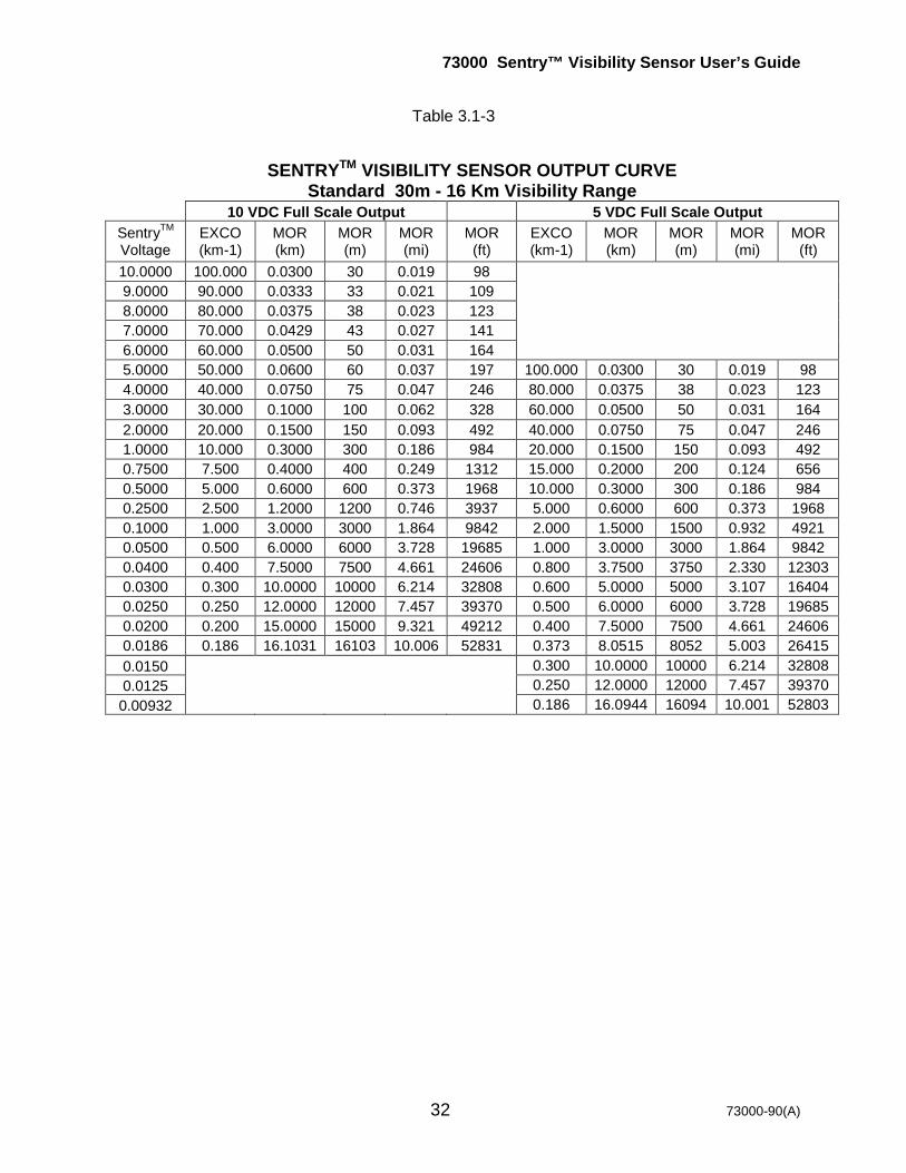
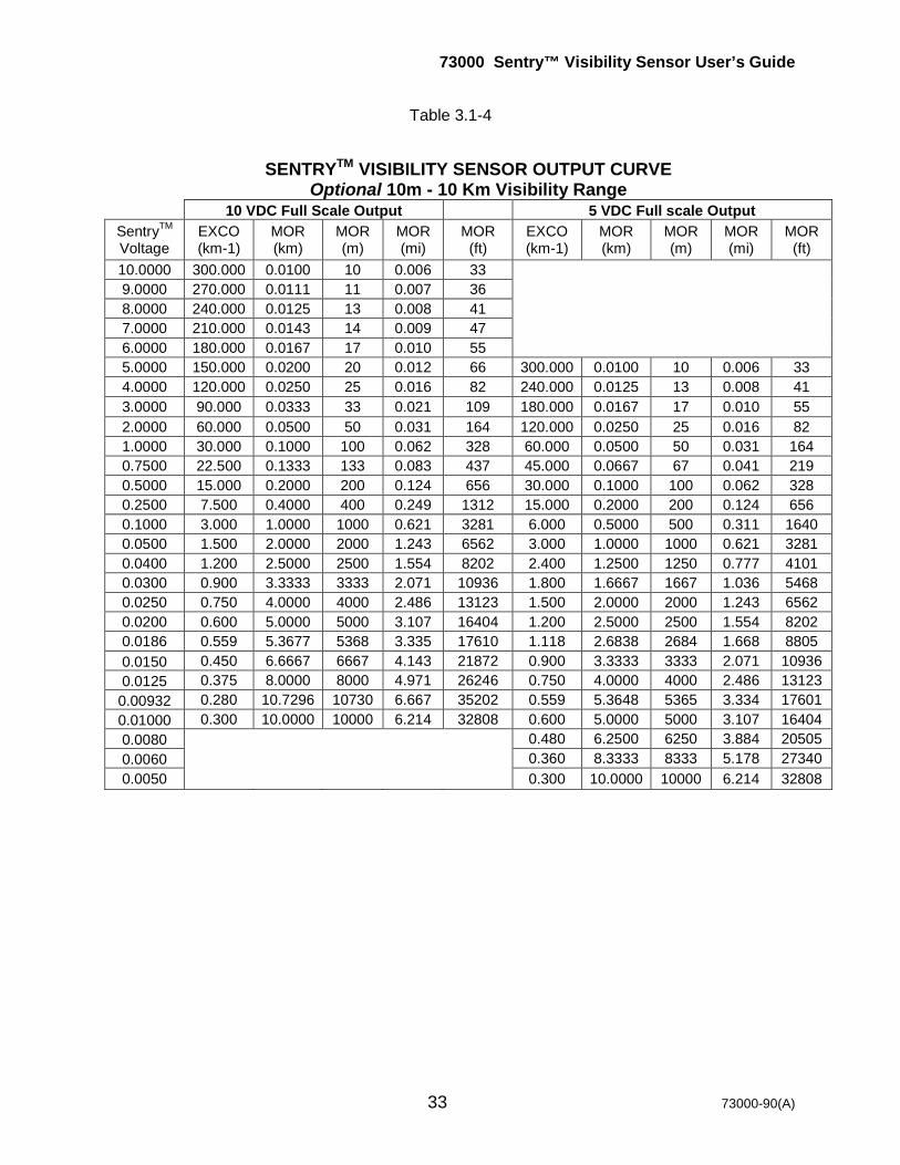
Table 3.1-3 below shows the relationship between sensor voltage, extinction coefficient (EXCO), and equivalent MOR (visibility) in kilometers, meters, statute miles, and feet for the standard 30m - 16 km visibility range with 0-10 VDC and 0-5 VDC voltage outputs. Table 3.1-4 repeats this information for the optional 10m - 10 km visibility range.
- Note - The Sentry output voltage may saturate at >10 VDC if there is too much scattering of light into
the receiver. This may occur with either the 0-5 VDC or 0-10 VDC analog output options.
73000 Sentry™ Visibility Sensor User’s Guide
32 73000-90(A)
Table 3.1-3
SENTRYTM VISIBILITY SENSOR OUTPUT CURVE Standard 30m - 16 Km Visibility Range
10 VDC Full Scale Output 5 VDC Full Scale Output SentryTM
Voltage EXCO (km-1)
MOR (km)
MOR (m)
MOR (mi)
MOR (ft)
EXCO (km-1)
MOR (km)
MOR (m)
MOR (mi)
MOR (ft)
10.0000 100.000 0.0300 30 0.019 98 9.0000 90.000 0.0333 33 0.021 109 8.0000 80.000 0.0375 38 0.023 123 7.0000 70.000 0.0429 43 0.027 141 6.0000 60.000 0.0500 50 0.031 164 5.0000 50.000 0.0600 60 0.037 197 100.000 0.0300 30 0.019 98 4.0000 40.000 0.0750 75 0.047 246 80.000 0.0375 38 0.023 123 3.0000 30.000 0.1000 100 0.062 328 60.000 0.0500 50 0.031 164 2.0000 20.000 0.1500 150 0.093 492 40.000 0.0750 75 0.047 246 1.0000 10.000 0.3000 300 0.186 984 20.000 0.1500 150 0.093 492 0.7500 7.500 0.4000 400 0.249 1312 15.000 0.2000 200 0.124 656 0.5000 5.000 0.6000 600 0.373 1968 10.000 0.3000 300 0.186 984 0.2500 2.500 1.2000 1200 0.746 3937 5.000 0.6000 600 0.373 1968 0.1000 1.000 3.0000 3000 1.864 9842 2.000 1.5000 1500 0.932 4921 0.0500 0.500 6.0000 6000 3.728 19685 1.000 3.0000 3000 1.864 9842 0.0400 0.400 7.5000 7500 4.661 24606 0.800 3.7500 3750 2.330 12303 0.0300 0.300 10.0000 10000 6.214 32808 0.600 5.0000 5000 3.107 16404 0.0250 0.250 12.0000 12000 7.457 39370 0.500 6.0000 6000 3.728 19685 0.0200 0.200 15.0000 15000 9.321 49212 0.400 7.5000 7500 4.661 24606 0.0186 0.186 16.1031 16103 10.006 52831 0.373 8.0515 8052 5.003 26415 0.0150 0.300 10.0000 10000 6.214 32808 0.0125 0.250 12.0000 12000 7.457 39370 0.00932 0.186 16.0944 16094 10.001 52803
73000 Sentry™ Visibility Sensor User’s Guide
33 73000-90(A)
Table 3.1-4
SENTRYTM VISIBILITY SENSOR OUTPUT CURVE Optional 10m - 10 Km Visibility Range
10 VDC Full Scale Output 5 VDC Full scale Output SentryTM
Voltage EXCO (km-1)
MOR (km)
MOR (m)
MOR (mi)
MOR (ft)
EXCO (km-1)
MOR (km)
MOR (m)
MOR (mi)
MOR (ft)
10.0000 300.000 0.0100 10 0.006 33 9.0000 270.000 0.0111 11 0.007 36 8.0000 240.000 0.0125 13 0.008 41 7.0000 210.000 0.0143 14 0.009 47 6.0000 180.000 0.0167 17 0.010 55 5.0000 150.000 0.0200 20 0.012 66 300.000 0.0100 10 0.006 33 4.0000 120.000 0.0250 25 0.016 82 240.000 0.0125 13 0.008 41 3.0000 90.000 0.0333 33 0.021 109 180.000 0.0167 17 0.010 55 2.0000 60.000 0.0500 50 0.031 164 120.000 0.0250 25 0.016 82 1.0000 30.000 0.1000 100 0.062 328 60.000 0.0500 50 0.031 164 0.7500 22.500 0.1333 133 0.083 437 45.000 0.0667 67 0.041 219 0.5000 15.000 0.2000 200 0.124 656 30.000 0.1000 100 0.062 328 0.2500 7.500 0.4000 400 0.249 1312 15.000 0.2000 200 0.124 656 0.1000 3.000 1.0000 1000 0.621 3281 6.000 0.5000 500 0.311 1640 0.0500 1.500 2.0000 2000 1.243 6562 3.000 1.0000 1000 0.621 3281 0.0400 1.200 2.5000 2500 1.554 8202 2.400 1.2500 1250 0.777 4101 0.0300 0.900 3.3333 3333 2.071 10936 1.800 1.6667 1667 1.036 5468 0.0250 0.750 4.0000 4000 2.486 13123 1.500 2.0000 2000 1.243 6562 0.0200 0.600 5.0000 5000 3.107 16404 1.200 2.5000 2500 1.554 8202 0.0186 0.559 5.3677 5368 3.335 17610 1.118 2.6838 2684 1.668 8805 0.0150 0.450 6.6667 6667 4.143 21872 0.900 3.3333 3333 2.071 10936 0.0125 0.375 8.0000 8000 4.971 26246 0.750 4.0000 4000 2.486 13123 0.00932 0.280 10.7296 10730 6.667 35202 0.559 5.3648 5365 3.334 17601 0.01000 0.300 10.0000 10000 6.214 32808 0.600 5.0000 5000 3.107 16404 0.0080 0.480 6.2500 6250 3.884 20505 0.0060 0.360 8.3333 8333 5.178 27340 0.0050 0.300 10.0000 10000 6.214 32808
73000 Sentry™ Visibility Sensor User’s Guide
34 73000-90(A)
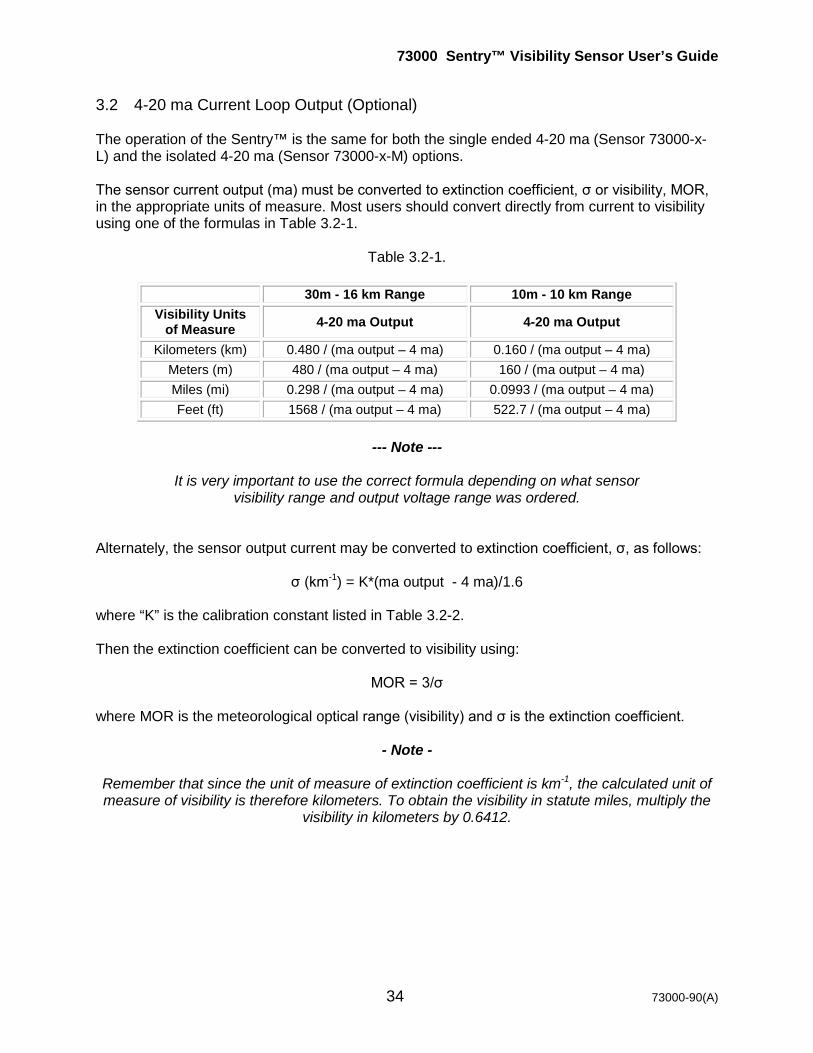
3.2 4-20 ma Current Loop Output (Optional) The operation of the Sentry™ is the same for both the single ended 4-20 ma (Sensor 73000-x-L) and the isolated 4-20 ma (Sensor 73000-x-M) options. The sensor current output (ma) must be converted to extinction coefficient, σ or visibility, MOR, in the appropriate units of measure. Most users should convert directly from current to visibility using one of the formulas in Table 3.2-1.
Table 3.2-1.
30m - 16 km Range 10m - 10 km Range Visibility Units
of Measure 4-20 ma Output 4-20 ma Output
Kilometers (km) 0.480 / (ma output – 4 ma) 0.160 / (ma output – 4 ma) Meters (m) 480 / (ma output – 4 ma) 160 / (ma output – 4 ma) Miles (mi) 0.298 / (ma output – 4 ma) 0.0993 / (ma output – 4 ma) Feet (ft) 1568 / (ma output – 4 ma) 522.7 / (ma output – 4 ma)
--- Note ---
It is very important to use the correct formula depending on what sensor
visibility range and output voltage range was ordered. Alternately, the sensor output current may be converted to extinction coefficient, σ, as follows:
σ (km-1) = K*(ma output - 4 ma)/1.6 where “K” is the calibration constant listed in Table 3.2-2. Then the extinction coefficient can be converted to visibility using:
MOR = 3/σ where MOR is the meteorological optical range (visibility) and σ is the extinction coefficient.
- Note - Remember that since the unit of measure of extinction coefficient is km-1, the calculated unit of measure of visibility is therefore kilometers. To obtain the visibility in statute miles, multiply the
visibility in kilometers by 0.6412.
73000 Sentry™ Visibility Sensor User’s Guide
35 73000-90(A)
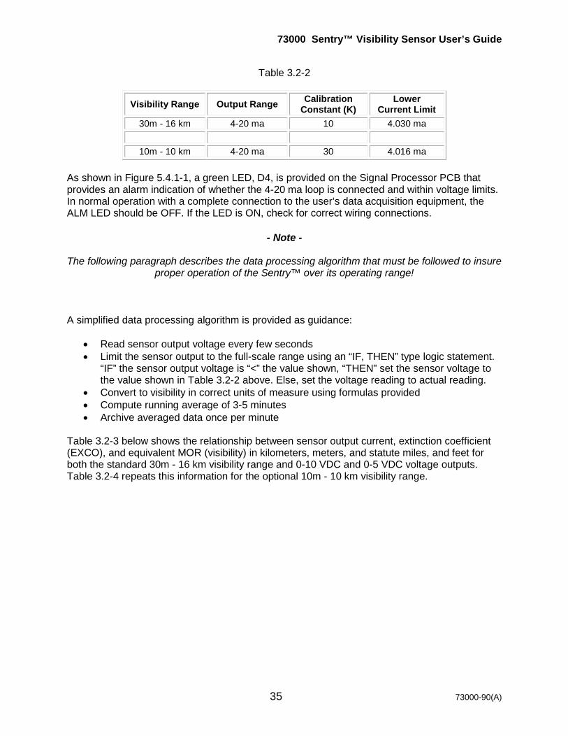
Table 3.2-2
Visibility Range Output Range Calibration Constant (K)
Lower Current Limit
30m - 16 km 4-20 ma 10 4.030 ma
10m - 10 km 4-20 ma 30 4.016 ma As shown in Figure 5.4.1-1, a green LED, D4, is provided on the Signal Processor PCB that provides an alarm indication of whether the 4-20 ma loop is connected and within voltage limits. In normal operation with a complete connection to the user’s data acquisition equipment, the ALM LED should be OFF. If the LED is ON, check for correct wiring connections.
- Note -
The following paragraph describes the data processing algorithm that must be followed to insure
proper operation of the Sentry™ over its operating range! A simplified data processing algorithm is provided as guidance:
• Read sensor output voltage every few seconds • Limit the sensor output to the full-scale range using an “IF, THEN” type logic statement.
“IF” the sensor output voltage is “<” the value shown, “THEN” set the sensor voltage to the value shown in Table 3.2-2 above. Else, set the voltage reading to actual reading.
• Convert to visibility in correct units of measure using formulas provided • Compute running average of 3-5 minutes • Archive averaged data once per minute
Table 3.2-3 below shows the relationship between sensor output current, extinction coefficient (EXCO), and equivalent MOR (visibility) in kilometers, meters, and statute miles, and feet for both the standard 30m - 16 km visibility range and 0-10 VDC and 0-5 VDC voltage outputs. Table 3.2-4 repeats this information for the optional 10m - 10 km visibility range.

73000 Sentry™ Visibility Sensor User’s Guide
36 73000-90(A)
Table 3.2-3
SENTRYTM VISIBILITY SENSOR OUTPUT Standard 30 - 16 Km Visibility Range
SentryTM
Voltage
Output Current
(ma)
EXCO (km-1)
MOR (km)
MOR (m)
MOR (mi) MOR (ft)
10.0000 20.000 100.000 0.0300 30 0.019 98 9.0000 18.400 90.000 0.0333 33 0.021 109 8.0000 16.800 80.000 0.0375 38 0.023 123 7.0000 15.200 70.000 0.0429 43 0.027 141 6.0000 13.600 60.000 0.0500 50 0.031 164 5.0000 12.000 50.000 0.0600 60 0.037 197 4.0000 10.400 40.000 0.0750 75 0.047 246 3.0000 8.800 30.000 0.1000 100 0.062 328 2.0000 7.200 20.000 0.1500 150 0.093 492 1.0000 5.600 10.000 0.3000 300 0.186 984 0.7500 5.200 7.500 0.4000 400 0.249 1312 0.5000 4.800 5.000 0.6000 600 0.373 1969 0.2500 4.400 2.500 1.2000 1200 0.746 3937 0.1000 4.160 1.000 3.0000 3000 1.864 9843 0.0500 4.080 0.500 6.0000 6000 3.728 19686 0.0400 4.064 0.400 7.5000 7500 4.661 24607 0.0300 4.048 0.300 10.0000 10000 6.214 32810 0.0250 4.040 0.250 12.0000 12000 7.457 39372 0.0200 4.032 0.200 15.0000 15000 9.321 49215 0.0187 4.030 0.187 16.0858 16086 9.996 52777

73000 Sentry™ Visibility Sensor User’s Guide
37 73000-90(A)
Table 3.2-4
SENTRY™ VISIBILITY SENSOR OUTPUT Optional 10m..10 Km Visibility Range
SentryTM
Voltage SentryTM
Current (ma) EXCO (km-1)
MOR (km)
MOR (m)
MOR (mi)
MOR (ft)
10.0000 20.000 300.000 0.010 10 0.006 33 9.0000 18.400 270.000 0.011 11 0.007 36 8.0000 16.800 240.000 0.013 13 0.008 41 7.0000 15.200 210.000 0.014 14 0.009 47 6.0000 13.600 180.000 0.017 17 0.010 55 5.0000 12.000 150.000 0.020 20 0.012 66 4.0000 10.400 120.000 0.025 25 0.016 82 3.0000 8.800 90.000 0.033 33 0.021 109 2.0000 7.200 60.000 0.050 50 0.031 164 1.2500 6.000 37.500 0.080 80 0.050 262 0.7500 5.200 22.500 0.133 133 0.083 437 0.5000 4.800 15.000 0.200 200 0.124 656 0.2500 4.400 7.500 0.400 400 0.249 1312 0.1000 4.160 3.000 1.000 1000 0.621 3281 0.0500 4.080 1.500 2.000 2000 1.243 6562 0.0450 4.072 1.350 2.222 2222 1.381 7291 0.0400 4.064 1.200 2.500 2500 1.554 8202 0.0350 4.056 1.050 2.857 2857 1.775 9374 0.0300 4.048 0.900 3.333 3333 2.071 10937 0.0250 4.040 0.750 4.000 4000 2.486 13124 0.0200 4.032 0.600 5.000 5000 3.107 16405 0.0150 4.024 0.450 6.667 6667 4.143 21873 0.0125 4.020 0.375 8.000 8000 4.971 26248 0.0100 4.016 0.300 10.000 10000 6.214 32810
73000 Sentry™ Visibility Sensor User’s Guide
38 73000-90(A)
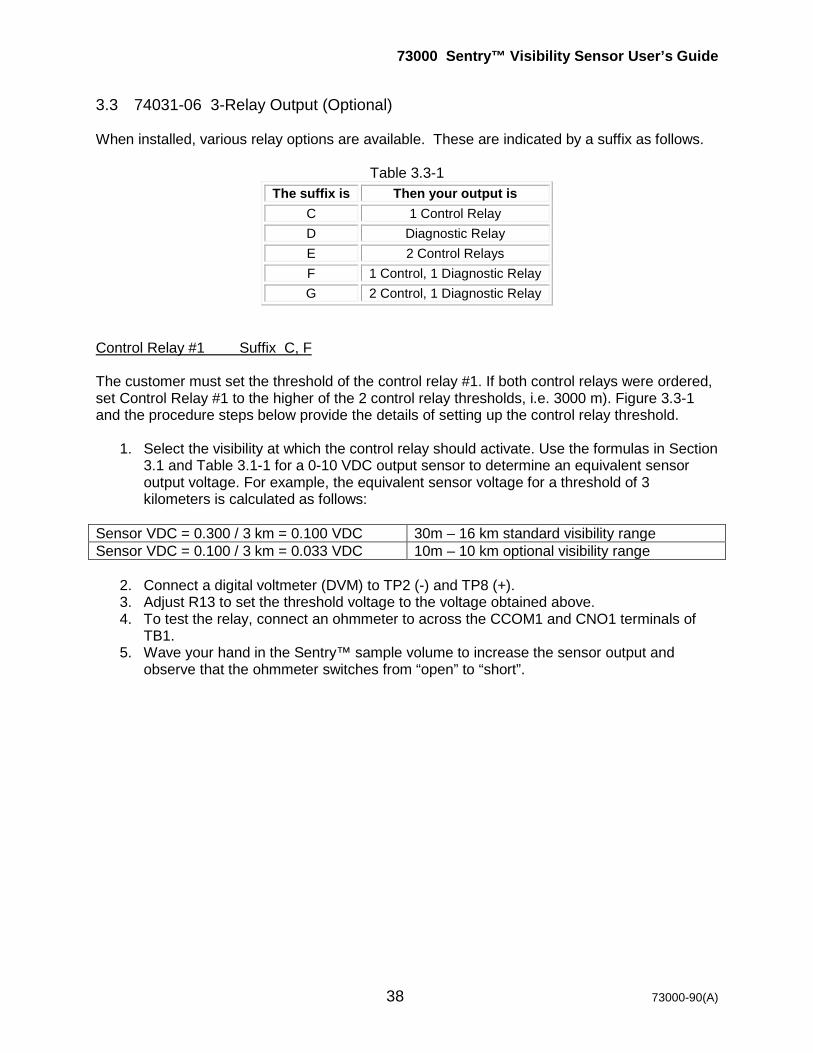
3.3 74031-06 3-Relay Output (Optional) When installed, various relay options are available. These are indicated by a suffix as follows.
Table 3.3-1 The suffix is Then your output is
C 1 Control Relay D Diagnostic Relay E 2 Control Relays F 1 Control, 1 Diagnostic Relay G 2 Control, 1 Diagnostic Relay
Control Relay #1 Suffix C, F The customer must set the threshold of the control relay #1. If both control relays were ordered, set Control Relay #1 to the higher of the 2 control relay thresholds, i.e. 3000 m). Figure 3.3-1 and the procedure steps below provide the details of setting up the control relay threshold.
1. Select the visibility at which the control relay should activate. Use the formulas in Section 3.1 and Table 3.1-1 for a 0-10 VDC output sensor to determine an equivalent sensor output voltage. For example, the equivalent sensor voltage for a threshold of 3 kilometers is calculated as follows:
Sensor VDC = 0.300 / 3 km = 0.100 VDC 30m – 16 km standard visibility range Sensor VDC = 0.100 / 3 km = 0.033 VDC 10m – 10 km optional visibility range
2. Connect a digital voltmeter (DVM) to TP2 (-) and TP8 (+). 3. Adjust R13 to set the threshold voltage to the voltage obtained above. 4. To test the relay, connect an ohmmeter to across the CCOM1 and CNO1 terminals of
TB1. 5. Wave your hand in the Sentry™ sample volume to increase the sensor output and
observe that the ohmmeter switches from “open” to “short”.
73000 Sentry™ Visibility Sensor User’s Guide
39 73000-90(A)
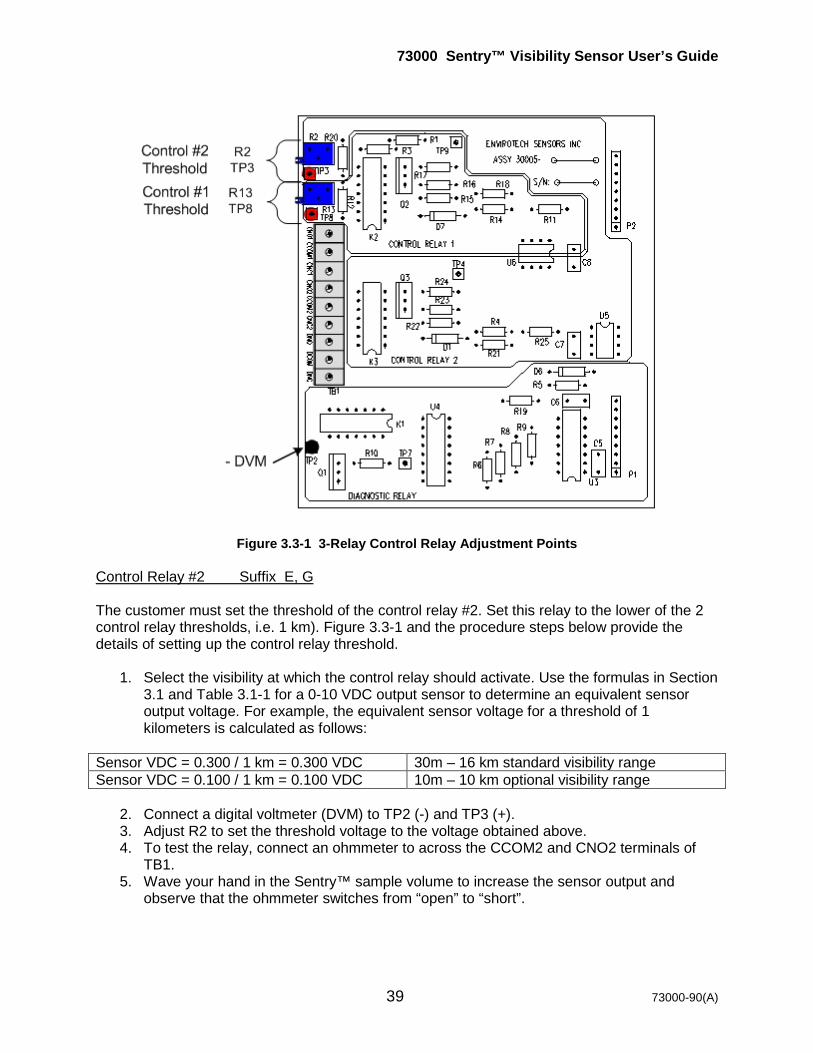
Figure 3.3-1 3-Relay Control Relay Adjustment Points Control Relay #2 Suffix E, G The customer must set the threshold of the control relay #2. Set this relay to the lower of the 2 control relay thresholds, i.e. 1 km). Figure 3.3-1 and the procedure steps below provide the details of setting up the control relay threshold.
1. Select the visibility at which the control relay should activate. Use the formulas in Section 3.1 and Table 3.1-1 for a 0-10 VDC output sensor to determine an equivalent sensor output voltage. For example, the equivalent sensor voltage for a threshold of 1 kilometers is calculated as follows:
Sensor VDC = 0.300 / 1 km = 0.300 VDC 30m – 16 km standard visibility range Sensor VDC = 0.100 / 1 km = 0.100 VDC 10m – 10 km optional visibility range
2. Connect a digital voltmeter (DVM) to TP2 (-) and TP3 (+). 3. Adjust R2 to set the threshold voltage to the voltage obtained above. 4. To test the relay, connect an ohmmeter to across the CCOM2 and CNO2 terminals of
TB1. 5. Wave your hand in the Sentry™ sample volume to increase the sensor output and
observe that the ohmmeter switches from “open” to “short”.

73000 Sentry™ Visibility Sensor User’s Guide
40 73000-90(A)
Diagnostic Relay Suffix D, F, G Once the diagnostic relay is connected to the user system, no further operation is required. The diagnostic relay provides a basic indication of Sentry™ status. If the relay activates, the sensor has detected a problem with DC input power, sensor derived voltages, or transmitter function. See Section 5.4 for assistance on corrective maintenance.
- Note -
For applications used to control foghorn or warning lights, it is recommended that the user supplied control system activate only after sensing several continuous minutes of activated relay
closure from the Sentry™ sensor. This will prevent momentary inadvertent activations of the warning system.
73000 Sentry™ Visibility Sensor User’s Guide
41 73000-90(A)
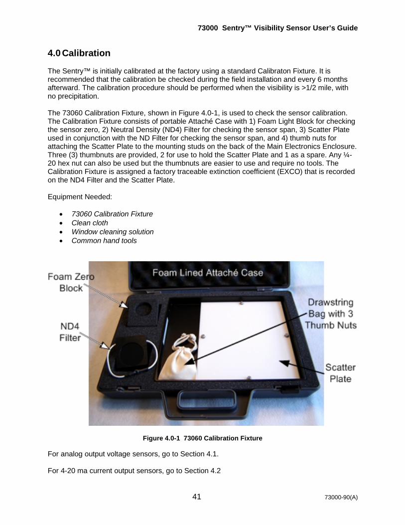
4.0 Calibration The Sentry™ is initially calibrated at the factory using a standard Calibraton Fixture. It is recommended that the calibration be checked during the field installation and every 6 months afterward. The calibration procedure should be performed when the visibility is >1/2 mile, with no precipitation. The 73060 Calibration Fixture, shown in Figure 4.0-1, is used to check the sensor calibration. The Calibration Fixture consists of portable Attaché Case with 1) Foam Light Block for checking the sensor zero, 2) Neutral Density (ND4) Filter for checking the sensor span, 3) Scatter Plate used in conjunction with the ND Filter for checking the sensor span, and 4) thumb nuts for attaching the Scatter Plate to the mounting studs on the back of the Main Electronics Enclosure. Three (3) thumbnuts are provided, 2 for use to hold the Scatter Plate and 1 as a spare. Any ¼-20 hex nut can also be used but the thumbnuts are easier to use and require no tools. The Calibration Fixture is assigned a factory traceable extinction coefficient (EXCO) that is recorded on the ND4 Filter and the Scatter Plate. Equipment Needed:
• 73060 Calibration Fixture • Clean cloth • Window cleaning solution • Common hand tools
Figure 4.0-1 73060 Calibration Fixture
For analog output voltage sensors, go to Section 4.1. For 4-20 ma current output sensors, go to Section 4.2
73000 Sentry™ Visibility Sensor User’s Guide
42 73000-90(A)
4.1 Procedure for Calibrating the Analog Voltage Output Sentry™ Sensor Note - This procedure may be used for the 0-5 VDC and 0-10 VDC analog outputs. Step Procedure
1 Inspect the Scatter Plate and ND4 Filter to insure they are clean, free of scratches, mechanically sound, and have matching serial numbers. If you are uncertain about the integrity of the Calibration Fixture, contact R.M. Young Company for information about returning it for service.
2 Clean the sensor windows with common window cleaner and remove any insect nests, spider webs or other debris under the hoods to ensure that the optical path is clear. If 73038 Hood Extensions are installed, loosen the retaining screw and remove them before cleaning the lenses. Leave then off until the calibration is complete.
3 If the sensor was off, turn the sensor power ON and wait at least 30 minutes. 4
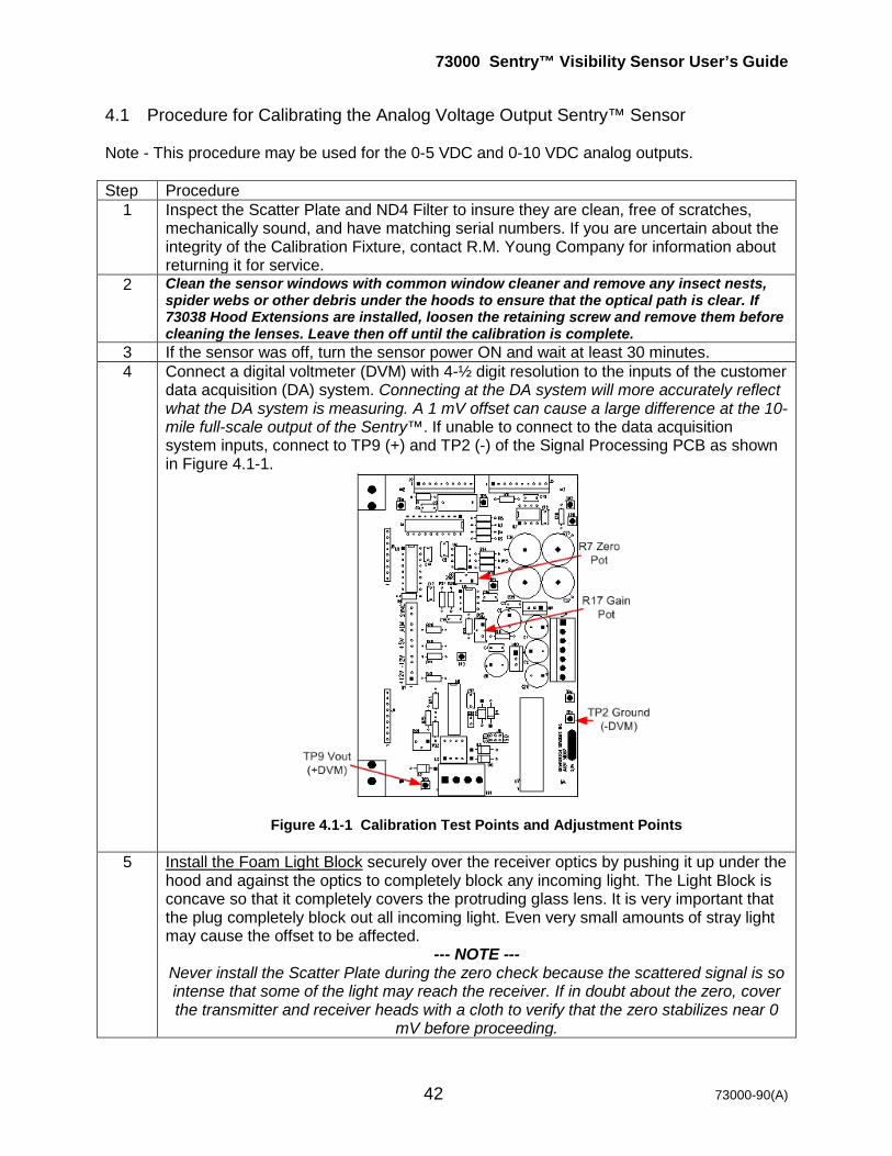
Connect a digital voltmeter (DVM) with 4-½ digit resolution to the inputs of the customer data acquisition (DA) system. Connecting at the DA system will more accurately reflect what the DA system is measuring. A 1 mV offset can cause a large difference at the 10-mile full-scale output of the Sentry™. If unable to connect to the data acquisition system inputs, connect to TP9 (+) and TP2 (-) of the Signal Processing PCB as shown in Figure 4.1-1.
Figure 4.1-1 Calibration Test Points and Adjustment Points
5 Install the Foam Light Block securely over the receiver optics by pushing it up under the hood and against the optics to completely block any incoming light. The Light Block is concave so that it completely covers the protruding glass lens. It is very important that the plug completely block out all incoming light. Even very small amounts of stray light may cause the offset to be affected.
--- NOTE --- Never install the Scatter Plate during the zero check because the scattered signal is so intense that some of the light may reach the receiver. If in doubt about the zero, cover the transmitter and receiver heads with a cloth to verify that the zero stabilizes near 0
mV before proceeding.

73000 Sentry™ Visibility Sensor User’s Guide
43 73000-90(A)
6 Wait 5 minutes for the signal to stabilize. 7 Read the DVM and adjust R7 (Zero Pot) of the Signal Processing PCB to 0.0 +/- 0.5
mV. 8 Remove the Foam Light Block and store it in the Attaché Case. 9 Install the ND4 Filter securely over the receiver optics by pushing it up under the hood
and against the optics to completely block any incoming light. Stretch the elastic cord around the back of the RX Head to hold the filter in place as shown in Figure 4.1-2.
Figure 4.1-2 Installation of ND4 Filter
10 Install the Scatter Plate on the threaded studs on the back of the Main Electronics Enclosure using the thumbnuts supplied in the 73060 Calibration Fixture as shown in Figure 4.1-3. Note the Scatter Plate orientation. The Plate installs with the ¼” circular mounting hole on the top stud and the ¼” slot on the bottom stud. When installed correctly, the top of the plate will be flush with the top of the sensor cross arm.
Figure 4.1-3 Installing the Scatter Plate
11 Wait 5 minutes for the signal to stabilize. 12 Record the EXCO written on the Calibration Fixture: EXCO = _________/km
Thumb Screw(2 PLCS)
Scatter PlateTop of Scatter
Plate Level withTop of Sensor
Cross Arm
73000 Sentry™ Visibility Sensor User’s Guide
44 73000-90(A)
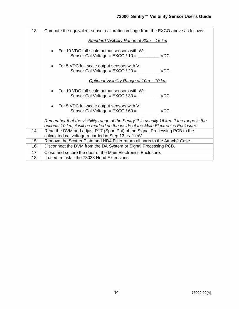
13 Compute the equivalent sensor calibration voltage from the EXCO above as follows:
Standard Visibility Range of 30m – 16 km
• For 10 VDC full-scale output sensors with W: Sensor Cal Voltage = EXCO / 10 = _________ VDC
• For 5 VDC full-scale output sensors with V:
Sensor Cal Voltage = EXCO / 20 = _________ VDC
Optional Visibility Range of 10m – 10 km
• For 10 VDC full-scale output sensors with W: Sensor Cal Voltage = EXCO / 30 = _________ VDC
• For 5 VDC full-scale output sensors with V:
Sensor Cal Voltage = EXCO / 60 = _________ VDC Remember that the visibility range of the Sentry™ is usually 16 km. If the range is the optional 10 km, it will be marked on the inside of the Main Electronics Enclosure.
14 Read the DVM and adjust R17 (Span Pot) of the Signal Processing PCB to the calculated cal voltage recorded in Step 13, +/-1 mV.
15 Remove the Scatter Plate and ND4 Filter return all parts to the Attaché Case. 16 Disconnect the DVM from the DA System or Signal Processing PCB. 17 Close and secure the door of the Main Electronics Enclosure. 18 If used, reinstall the 73038 Hood Extensions.

73000 Sentry™ Visibility Sensor User’s Guide
45 73000-90(A)
4.2 Procedure for Calibrating the Sentry™ with 4-20 ma Current Output Note - This procedure may be used with either the standard single ended or the isolated 4-20 ma current output. Step Procedure
1 Inspect the Scatter Plate and ND4 Filter to insure they are clean, free of scratches, mechanically sound, and have matching serial numbers. If you are uncertain about the integrity of the Calibration Fixture, contact R.M. Young Company for information about returning it for service.
2 Clean the sensor windows with common window cleaner and remove any insect nests, spider webs or other debris under the hoods to ensure that the optical path is clear. If 73038 Hood Extensions are installed, loosen the retaining screw and remove them before cleaning the lenses. Leave then off until the calibration is complete.
3 If the sensor was off, turn the sensor power ON and wait 30 minutes. 4
Connect a digital current meter with 4-½ digit resolution to the 4-20 ma output of TB1 of the Signal Processor PCB as shown in Figure 2.3.2-1.
5 Install the Foam Light Block securely over the receiver optics by pushing it up under the hood and against the optics to completely block any incoming light. The Light Block is concave so that it completely covers the protruding glass lens. It is very important that the plug completely block out all incoming light. Even very small amounts of stray light may cause the offset to be affected.
--- NOTE --- Never install the Scatter Plate during the zero check because the scattered signal is so intense that some of the light may reach the receiver. If in doubt about the zero, cover the transmitter and receiver heads with a cloth to verify that the zero stabilizes near 0
mV before proceeding. 6 Wait 5 minutes for the signal to stabilize. 7 Read the DVM and adjust R7 (Zero Pot) of the Signal Processing PCB to 4.000 ma. 8 Remove the Light Block and store it in the Attaché Case. 9 Install the ND4 Filter securely over the receiver optics by pushing it up under the hood
and against the optics to completely block any incoming light. Stretch the elastic cord around the back of the RX Head to hold the filter in place as shown in Figure 4.1-2.
10 Install the Scatter Plate on the threaded studs on the back of the Main Electronics Enclosure using the thumbnuts supplied in the 73060 Calibration Fixture as shown in Figure 4.1-3. Note the Scatter Plate orientation. The Plate installs with the ¼” circular mounting hole on the top stud and the ¼” slot on the bottom stud. When installed correctly, the top of the plate will be flush with the top of the sensor cross arm.
11 Wait 5 minutes for the signal to stabilize.
73000 Sentry™ Visibility Sensor User’s Guide
46 73000-90(A)
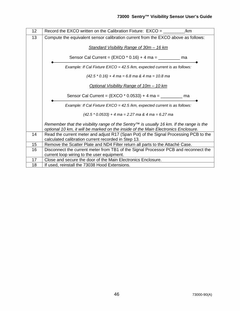
12 Record the EXCO written on the Calibration Fixture: EXCO = _________/km 13 Compute the equivalent sensor calibration current from the EXCO above as follows:
Standard Visibility Range of 30m – 16 km
Sensor Cal Current = (EXCO * 0.16) + 4 ma = _________ ma
Example: If Cal Fixture EXCO = 42.5 /km, expected current is as follows:
(42.5 * 0.16) + 4 ma = 6.8 ma & 4 ma = 10.8 ma
Optional Visibility Range of 10m – 10 km
Sensor Cal Current = (EXCO * 0.0533) + 4 ma = _________ ma
Example: If Cal Fixture EXCO = 42.5 /km, expected current is as follows:
(42.5 * 0.0533) + 4 ma = 2.27 ma & 4 ma = 6.27 ma
Remember that the visibility range of the Sentry™ is usually 16 km. If the range is the optional 10 km, it will be marked on the inside of the Main Electronics Enclosure.
14 Read the current meter and adjust R17 (Span Pot) of the Signal Processing PCB to the calculated calibration current recorded in Step 13.
15 Remove the Scatter Plate and ND4 Filter return all parts to the Attaché Case. 16 Disconnect the current meter from TB1 of the Signal Processor PCB and reconnect the
current loop wiring to the user equipment. 17 Close and secure the door of the Main Electronics Enclosure. 18 If used, reinstall the 73038 Hood Extensions.

73000 Sentry™ Visibility Sensor User’s Guide
47 73000-90(A)
5.0 Maintenance 5.1 R.M. Young Company Product Warranty:
Warranty
R.M. Young Company (Seller) warrants this Sentry Visibility Sensor to be free of defects in material and workmanship under normal conditions for a period of twenty-four (24) months from date of shipment subject to the following:
• Warranty does not apply to products that have been subject to mishandling, misapplication, modification, abuse, neglect, accident of nature, or shipping damage.
• The Seller is not liable for incidental or consequential damage caused by its products including but not limited to: damages for loss of use, income, profit, or good will; losses sustained as a result of death or injury to any persons; and/or damages to property other than the product. In no case shall the Seller’s liability exceed the price paid for the product.
• This warranty is expressly in lieu of any other expressed or implied warranty of merchantability or fitness for a particular purpose, and of any obligations or liabilities on the part of the Seller or its employees or agents.
5.2 Correcting Defects Under the Warranty Contact R.M. Young Company to discuss the reason for returning a product and to obtain the return material authorization (RMA) number. Items to be returned to R.M. Young Company for any reason must be accompanied by a return material authorization number. Mark the outside of all shipping cartons and correspondence with the RMA number. Buyer shall return the product to R.M. Young Company , prepaid transportation. Upon receipt, R.M. Young Company will evaluate the product to determine the cause of the reported problem and the applicability of the warranty. Products deemed to be covered by the warranty will be repaired by R.M. Young Company at no charge to the Buyer and returned to the Buyer, prepaid surface transportation. R.M. Young Company will prepare an estimate for products not under warranty and submit the quotation to the Buyer for approval. Contact R.M. Young Company or visit http://www.youngusa.com for information on the return of waste electrical parts per WEEE (The Waste Electronic and Electrical Equipment Directive) directive 2002/96/EC.
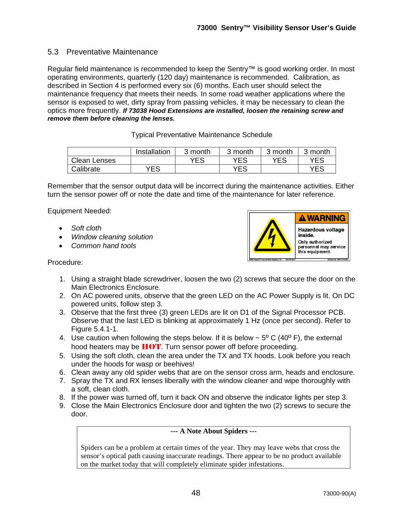
73000 Sentry™ Visibility Sensor User’s Guide
48 73000-90(A)
5.3 Preventative Maintenance Regular field maintenance is recommended to keep the Sentry™ is good working order. In most operating environments, quarterly (120 day) maintenance is recommended. Calibration, as described in Section 4 is performed every six (6) months. Each user should select the maintenance frequency that meets their needs. In some road weather applications where the sensor is exposed to wet, dirty spray from passing vehicles, it may be necessary to clean the optics more frequently. If 73038 Hood Extensions are installed, loosen the retaining screw and remove them before cleaning the lenses.
Typical Preventative Maintenance Schedule
Installation 3 month 3 month 3 month 3 month Clean Lenses YES YES YES YES Calibrate YES YES YES
Remember that the sensor output data will be incorrect during the maintenance activities. Either turn the sensor power off or note the date and time of the maintenance for later reference. Equipment Needed:
• Soft cloth • Window cleaning solution • Common hand tools
Procedure:
1. Using a straight blade screwdriver, loosen the two (2) screws that secure the door on the Main Electronics Enclosure.
2. On AC powered units, observe that the green LED on the AC Power Supply is lit. On DC powered units, follow step 3.
3. Observe that the first three (3) green LEDs are lit on D1 of the Signal Processor PCB. Observe that the last LED is blinking at approximately 1 Hz (once per second). Refer to Figure 5.4.1-1.
4. Use caution when following the steps below. If it is below ~ 5º C (40º F), the external hood heaters may be HOT. Turn sensor power off before proceeding.
5. Using the soft cloth, clean the area under the TX and TX hoods. Look before you reach under the hoods for wasp or beehives!
6. Clean away any old spider webs that are on the sensor cross arm, heads and enclosure. 7. Spray the TX and RX lenses liberally with the window cleaner and wipe thoroughly with
a soft, clean cloth. 8. If the power was turned off, turn it back ON and observe the indicator lights per step 3. 9. Close the Main Electronics Enclosure door and tighten the two (2) screws to secure the
door.
--- A Note About Spiders --- Spiders can be a problem at certain times of the year. They may leave webs that cross the sensor’s optical path causing inaccurate readings. There appear to be no product available on the market today that will completely eliminate spider infestations.
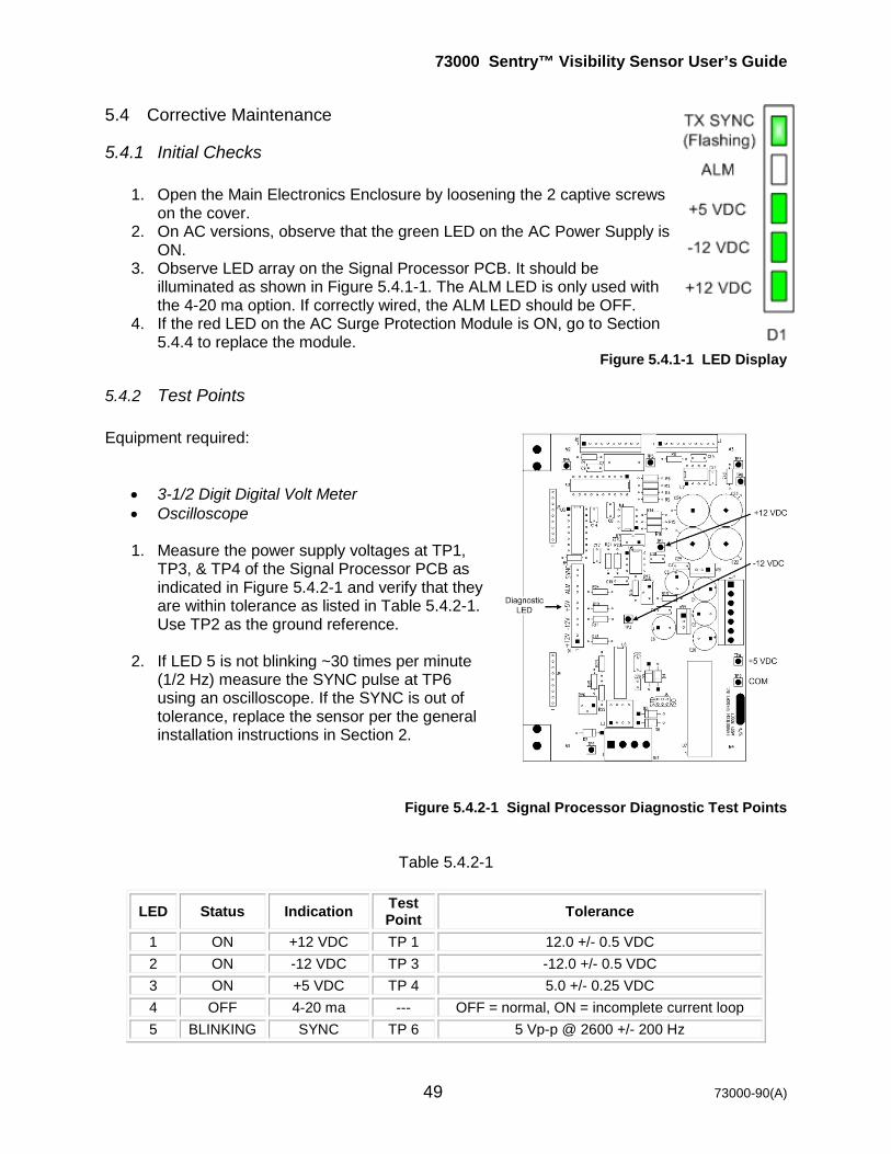
73000 Sentry™ Visibility Sensor User’s Guide
49 73000-90(A)
5.4 Corrective Maintenance
5.4.1 Initial Checks 1. Open the Main Electronics Enclosure by loosening the 2 captive screws
on the cover. 2. On AC versions, observe that the green LED on the AC Power Supply is
ON. 3. Observe LED array on the Signal Processor PCB. It should be
illuminated as shown in Figure 5.4.1-1. The ALM LED is only used with the 4-20 ma option. If correctly wired, the ALM LED should be OFF.
4. If the red LED on the AC Surge Protection Module is ON, go to Section 5.4.4 to replace the module.
Figure 5.4.1-1 LED Display
5.4.2 Test Points Equipment required:
• 3-1/2 Digit Digital Volt Meter • Oscilloscope
1. Measure the power supply voltages at TP1,
TP3, & TP4 of the Signal Processor PCB as indicated in Figure 5.4.2-1 and verify that they are within tolerance as listed in Table 5.4.2-1. Use TP2 as the ground reference.
2. If LED 5 is not blinking ~30 times per minute
(1/2 Hz) measure the SYNC pulse at TP6 using an oscilloscope. If the SYNC is out of tolerance, replace the sensor per the general installation instructions in Section 2.
Figure 5.4.2-1 Signal Processor Diagnostic Test Points
Table 5.4.2-1
LED Status Indication Test Point Tolerance
1 ON +12 VDC TP 1 12.0 +/- 0.5 VDC 2 ON -12 VDC TP 3 -12.0 +/- 0.5 VDC 3 ON +5 VDC TP 4 5.0 +/- 0.25 VDC 4 OFF 4-20 ma --- OFF = normal, ON = incomplete current loop 5 BLINKING SYNC TP 6 5 Vp-p @ 2600 +/- 200 Hz

73000 Sentry™ Visibility Sensor User’s Guide
50 73000-90(A)
AC Versions - If TP1, TP3, or TP4 are out of tolerance, measure the voltages from the main AC Power Supply as shown in Figure 5.4.2-2 and the Table 5.4.2-2 below. Use the power supply terminal marked “Com” as the ground reference.
Table 5.4.2-2
Name Wire Color Tolerance +V2 Red 15.0 +/-0.5 VDC COM Black 15 VDC Return V3 White -15.0 +/-0.5 VDC
+5V Green 5.0 +/-0.25 VDC
Figure 5.4.2-2 AC Power Supply Test Points
1. If the AC Power Supply voltages are within tolerance but the Signal Processor voltages are out of tolerance, replace the sensor per the general installation instructions in Section 2.
2. If the AC Power Supply voltages are out of tolerance, replace the AC Power Supply per
the remove & replace instructions in Section 5.4.4. DC Versions - If TP1, TP3, or TP4 are out of tolerance, measure the voltages from the DC
Power Supply PCB as shown in Figure 5.4.2-3 and Table 5.4.2-3 below.
--- Note --- When measuring the TP1 input voltage, use TB1-2 (12 VDC common) as the
reference. For the TP3, TP4, and TP5output voltages, use TP2 of the DC Power Supply PCB as the ground reference.
Table 5.4.2-3
Test Point Tolerance
TP1 10-36 VDC TP3 +15.0 +/-0.5 VDC TP4 -15.0 +/-0.5 VDC TP5 5.0 +/-0.25 VDC
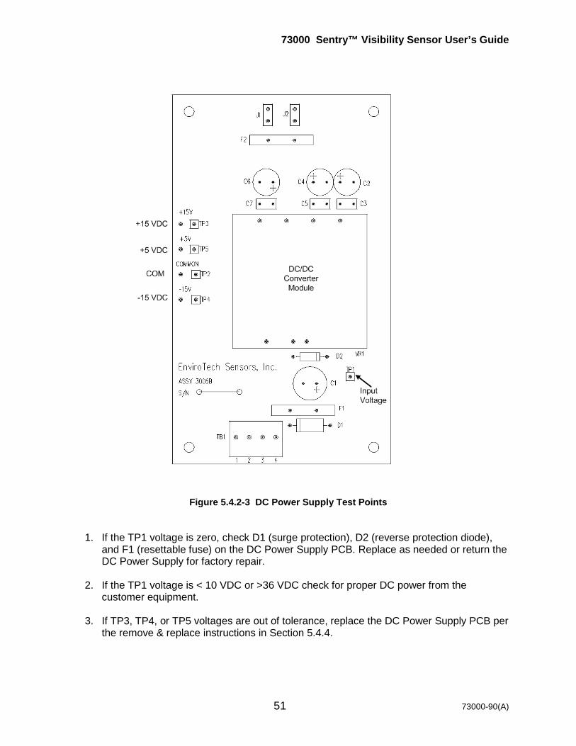
73000 Sentry™ Visibility Sensor User’s Guide
51 73000-90(A)
Figure 5.4.2-3 DC Power Supply Test Points
1. If the TP1 voltage is zero, check D1 (surge protection), D2 (reverse protection diode), and F1 (resettable fuse) on the DC Power Supply PCB. Replace as needed or return the DC Power Supply for factory repair.
2. If the TP1 voltage is < 10 VDC or >36 VDC check for proper DC power from the
customer equipment.
3. If TP3, TP4, or TP5 voltages are out of tolerance, replace the DC Power Supply PCB per the remove & replace instructions in Section 5.4.4.
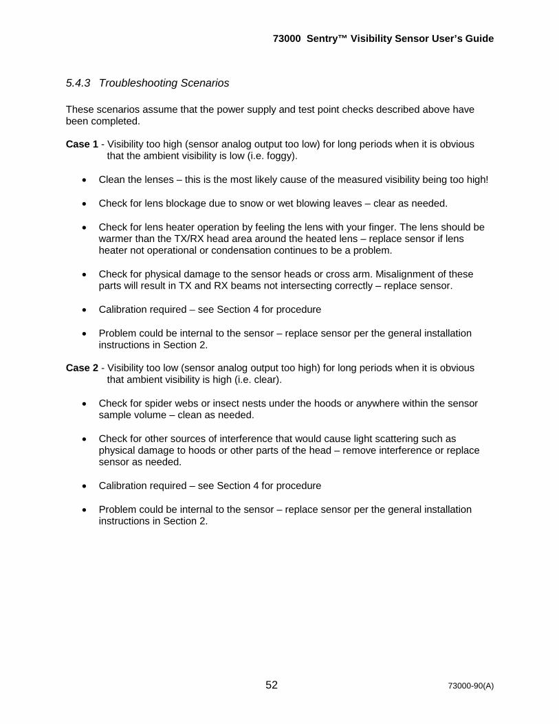
73000 Sentry™ Visibility Sensor User’s Guide
52 73000-90(A)
5.4.3 Troubleshooting Scenarios These scenarios assume that the power supply and test point checks described above have been completed. Case 1 - Visibility too high (sensor analog output too low) for long periods when it is obvious
that the ambient visibility is low (i.e. foggy).
• Clean the lenses – this is the most likely cause of the measured visibility being too high!
• Check for lens blockage due to snow or wet blowing leaves – clear as needed.
• Check for lens heater operation by feeling the lens with your finger. The lens should be warmer than the TX/RX head area around the heated lens – replace sensor if lens heater not operational or condensation continues to be a problem.
• Check for physical damage to the sensor heads or cross arm. Misalignment of these
parts will result in TX and RX beams not intersecting correctly – replace sensor.
• Calibration required – see Section 4 for procedure
• Problem could be internal to the sensor – replace sensor per the general installation instructions in Section 2.
Case 2 - Visibility too low (sensor analog output too high) for long periods when it is obvious
that ambient visibility is high (i.e. clear).
• Check for spider webs or insect nests under the hoods or anywhere within the sensor sample volume – clean as needed.
• Check for other sources of interference that would cause light scattering such as
physical damage to hoods or other parts of the head – remove interference or replace sensor as needed.
• Calibration required – see Section 4 for procedure
• Problem could be internal to the sensor – replace sensor per the general installation instructions in Section 2.
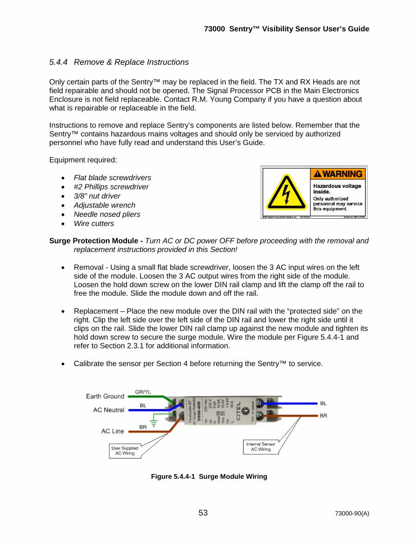
73000 Sentry™ Visibility Sensor User’s Guide
53 73000-90(A)
5.4.4 Remove & Replace Instructions Only certain parts of the Sentry™ may be replaced in the field. The TX and RX Heads are not field repairable and should not be opened. The Signal Processor PCB in the Main Electronics Enclosure is not field replaceable. Contact R.M. Young Company if you have a question about what is repairable or replaceable in the field. Instructions to remove and replace Sentry’s components are listed below. Remember that the Sentry™ contains hazardous mains voltages and should only be serviced by authorized personnel who have fully read and understand this User’s Guide. Equipment required:
• Flat blade screwdrivers • #2 Phillips screwdriver • 3/8” nut driver • Adjustable wrench • Needle nosed pliers • Wire cutters
Surge Protection Module - Turn AC or DC power OFF before proceeding with the removal and
replacement instructions provided in this Section!
• Removal - Using a small flat blade screwdriver, loosen the 3 AC input wires on the left side of the module. Loosen the 3 AC output wires from the right side of the module. Loosen the hold down screw on the lower DIN rail clamp and lift the clamp off the rail to free the module. Slide the module down and off the rail.
• Replacement – Place the new module over the DIN rail with the “protected side” on the
right. Clip the left side over the left side of the DIN rail and lower the right side until it clips on the rail. Slide the lower DIN rail clamp up against the new module and tighten its hold down screw to secure the surge module. Wire the module per Figure 5.4.4-1 and refer to Section 2.3.1 for additional information.
• Calibrate the sensor per Section 4 before returning the Sentry™ to service.
Figure 5.4.4-1 Surge Module Wiring

73000 Sentry™ Visibility Sensor User’s Guide
54 73000-90(A)
AC Power Supply - Turn AC or DC power OFF before proceeding with the removal and replacement instructions provided in this Section!
• Removal – Disconnect the signal wiring from TB1 terminal board on the Signal
Processor PCB or output option board if installed. Using a small flat blade screwdriver, loosen the 3 AC input wires on the left side of the surge module. Using a 3/8” nut driver, loosen the hex nut on the 10-32 ground screw located in the lower right corner of the base plate. Lift off the green/yellow wire that connects to the Main Enclosure ¼-20 ground stud. Using a long flat blade screwdriver, unscrew the 4 white base plate corner screws. Carefully tip the base plate assembly out of the enclosure. Unplug the white 7-pin connector from J1 on the right side of the Signal Processor PCB. Using a small flat blade screwdriver, loosen the blue and brown AC wires on the right side of the power supply. Loosen the 2 screws that secure the AC Power Supply to the base plate.
• Replacement – Install and tighten the 2 screws that secure the new AC Power Supply to
the base plate. Plug the white 7-pin connector into J1 of the Signal Processor PCB. Reinstall the base plate assembly into the enclosure and tighten the 4 corner screws securely. Reconnect the green/yellow ground wire from the Main Enclosure ground stud to the base plate ground stud. Rewire the AC power input per Figures 5.4.2-2 and A1 as needed. Rewire the user signal wires per Section 2.4.
• Calibrate the sensor per Section 4 before returning the Sentry™ to service.
DC Power Supply - Turn AC or DC power OFF before proceeding with the removal and
replacement instructions provided in this Section!
• Removal – Using a small flat blade screwdriver, loosen the 2 DC input power wires from TB1 of the DC Power Supply PCB. Unplug the white 7-pin connector from J1 on the right side of the Signal Processor PCB. Using a small flat blade screwdriver, unscrew the 4 corner screws that hold the DC Power Supply PCB to the base plate. Carefully lift the PCB out of the enclosure.
• Replacement – Place the new DC Power Supply PCB over the base plate standoffs and
replace the 4 screws and washers to secure it. Plug the white 7-pin connector into J1 of the Signal Processor PCB. Rewire the DC power input wires to TB1 per Section 2.3.2.
• Calibrate the sensor per Section 4 before returning the Sentry™ to service.

73000 Sentry™ Visibility Sensor User’s Guide
55 73000-90(A)
Output Option PCB - Turn AC or DC power OFF before proceeding with the removal and replacement instructions provided in this Section!
• Removal – Using a small flat blade screwdriver, loosen the 2 signal wires from TB1
and/or TB2 of the Output Option PCB. Carefully slide the PCB out of the card guides of the Signal Processor PCB.
• Replacement – Place the new Output Option PCB into the card guides of the Signal
Processor PCB and carefully seat the mating connectors. Rewire the user signal wires to TB1 and/or TB2 per Section 2.4.2.
• Calibrate the sensor per Section 4 before returning the Sentry™ to service.
5.5 Field Replaceable Units (FRU’s) Only certain parts of the Sentry™ may be replaced in the field. The TX and RX Heads are not field repairable and should not be opened. The Signal Processor PCB in the Main Electronics Enclosure is not field replaceable without factory training. Table 5.5-1 provides a list of the field replaceable units. Contact R.M. Young Company for information about what FRUs are applicable to your Sentry™.
Table 5.5-1
FRU Description FRU P/N AC Surge Protection Module 74031-02 Switching AC Power Supply Assy 73031-02 DC Power Supply Assy 73021-02 Signal Processor PCB Note1 73020-02 3-Relay Output Option PCB Note1 74031-06-xxx AC External Hood Heater Transformer 73031-02
Note1 – You must order the exact replacement – see your PCB for complete part number. 5.6 Training Additional training is available from R.M. Young Company . Custom courses are offered in such areas as visibility theory and practice, siting guidelines, and installation & maintenance. These training courses are available at the R.M. Young Company . factory, at the user’s facility, or in the field. Contact R.M. Young Company . for more information. Training is recommended for the user to become an authorized and knowledgeable service person.


73000 Sentry™ Visibility Sensor User’s Guide
56 73000-90(A)
Appendix

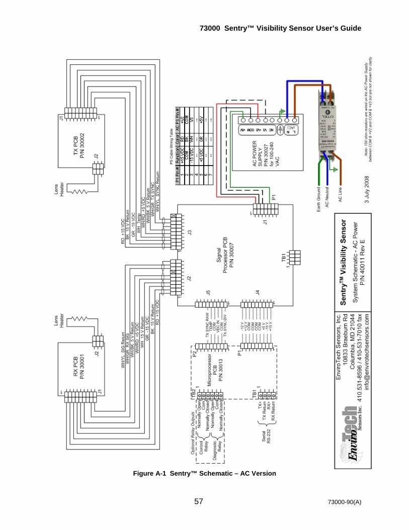
73000 Sentry™ Visibility Sensor User’s Guide
57 73000-90(A)
Figure A-1 Sentry™ Schematic – AC Version

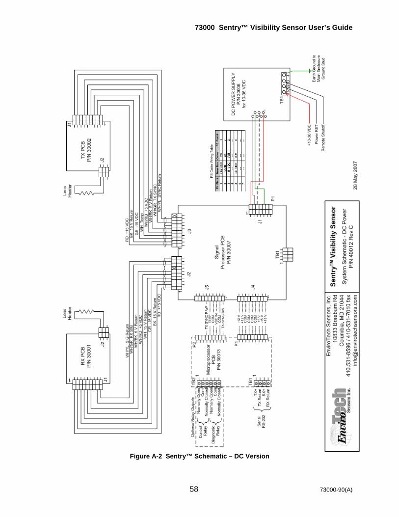
73000 Sentry™ Visibility Sensor User’s Guide
58 73000-90(A)
Figure A-2 Sentry™ Schematic – DC Version

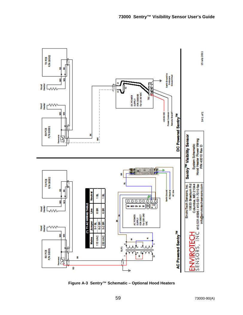
73000 Sentry™ Visibility Sensor User’s Guide
59 73000-90(A)
Figure A-3 Sentry™ Schematic – Optional Hood Heaters
