seo et al, j civil nviron ng 2013, 3:2 ivil nvironental ngineering · pdf fileby obtaining the...
TRANSCRIPT

Volume 3 • Issue 2 • 1000131J Civil Environ EngISSN: 2165-784X JCEE, an open access journal
Civil & Environmental EngineeringSeo et al., J Civil Environ Eng 2013, 3:2
http://dx.doi.org/10.4172/2165-784X.1000131
Research Article Open Access
Numerical Methodology for Predicting the Nonlinear Elastic Deflection of Curved Beams and Plates Using Nonlinear Integral EquationsJung Kwan Seo, So Young Bae, Jeom Kee Paik and Taek Soo Jang*
The Ship and Offshore Research Institute, Pusan National University, Busan, Korea
AbstractShips, ship-shaped offshore structures, land-based structures and aerospace structures typically consist of various
curved beam and plate components. An important issue is how to manufacture and construct systems correctly and accurately when their variously shaped curved beams and plates display structural nonlinear behaviour. Multi-point forming is a general process that can be used to form variously shaped curved plates and beams. It has been difficult to apply the integrated systems to thin and/or thick metal plates and beams that have the characteristic of non-linear structural mechanics, such as nonlinear behaviour when loading is applied to the plates. The aim of this study was to derive a simplified numerical calculation based on the formulation of a nonlinear integral equation and a mathematical solution, to predict the nonlinear elastic deflection, load profile and elastic foundation of curved plates or/and beams during the early stages of the advanced manufacturing process of plate and beam formation. The validity of the method is demonstrated through simulations of the proposed numerical approach with experimental results.
*Corresponding author: Taek Soo Jang, The Ship and Offshore Research Institute, Pusan National University, Busan, Korea, Tel: +82 51 510-2789 E-mail: [email protected]
Received October 17, 2013; Accepted November 20, 2013; Published November 25, 2013
Citation: Seo JK, So Bae Y, Paik JK, Jang TS (2013) Numerical Methodology for Predicting the Nonlinear Elastic Deflection of Curved Beams and Plates Using Nonlinear Integral Equations. J Civil Environ Eng 3: 131. doi:10.4172/2165-784X.1000131
Copyright: © 2013 Seo JK, et al. This is an open-access article distributed under the terms of the Creative Commons Attribution License, which permits unrestricted use, distribution, and reproduction in any medium, provided the original author and source are credited.
Keywords: Nonlinear structural behavior; Nonlinear integral equation; Curved plate/beam; Elastic foundation; Cold forming process
Nomenclaturea Length of beam
effb Effective breadth
E Young’s modulus of elasticity[ ( )]f u x Nonlinear restoration
G Green’s function
I Mass moment of inertia
k Spring force
( )L x Applied loading
( )p x Net loading
t Plate thickness
( )u x Vertical deflection
,x y Principal axes
β Convergence of parameter
1δ Maximum magnitude of curved beam edges
2δ Maximum magnitude of curved plate from original plate
(u)λ Nonlinear part of the beam deflection(x)π Linear part of the beam deflection
IntroductionThe general forming process for curved metal plates can be roughly
classified into two types, hot forming and cold forming, according to the thermal condition of the metal during the forming process. A typical method of hot forming is line heating, a popular technique used in shipyards to form sections of ship hulls using the properties of metal plates: heating for expansion and rapid cooling for contraction. Even today, skilled workers still perform the forming process using their empirical intuition, as shown in Figure 1, and no systematic method for ensuring effective formation has been developed.
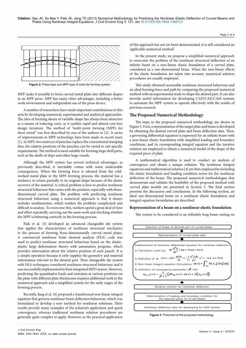
Cold forming can be categorised as either conventional solid die forming or multi-point forming (MPF) for sheet metal, as shown in Figure 2. MPF is a cold forming manufacturing technique that combines three-dimensional sheet metal with a pair of multi-point dies consisting of upper and lower matrices of square punches with spherical ends in an MPF press [1]. By controlling each punch, a sheet part can be manufactured along a specific predefined forming path. In this mode, the shape of the multi-point die (MPD) varies continuously during the forming process and all of the punches are kept in contact with the sheet at all times. Accordingly, the deforming load applied by the die is distributed throughout the sheet.
The flexibility of MPD and the variability of the forming path using
Figure 1: Workers using the line heating method.
Volume 3 • Issue 2 • 1000131J Civil Environ EngISSN: 2165-784X JCEE, an open access journal
Citation: Seo JK, So Bae Y, Paik JK, Jang TS (2013) Numerical Methodology for Predicting the Nonlinear Elastic Deflection of Curved Beams and Plates Using Nonlinear Integral Equations. J Civil Environ Eng 3: 131. doi:10.4172/2165-784X.1000131
Page 2 of 6
MPF make it possible to form curved metal plate into different shapes in an MPF press. MPF has many other advantages, including a better work environment and independent use of the press device.
A number of researchers have made important contributions in this area by developing numerical, experimental and analytical approaches. The idea of forming sheets of variable shape has always been attractive as a means of reducing costs, as it enables rapid and almost cost-free design iterations. The method of “multi-point forming (MPF) for sheet metal” was first described by one of the authors in [2]. A series of improvements in MPF technology have been made in recent years [1]. In MPF, two matrices of punches replace the conventional stamping dies; the relative positions of the punches can be varied to suit specific requirements. The method is most suitable for forming large shell parts, such as the shells of ships and other large vessels.
Although the MPF system has several technical advantages, as previously described, it inevitably comes with some undesirable consequences. When the forming force is released from the cold-worked metal plate in the MPF forming process, the material has a tendency to return partially to its original shape because of the elastic recovery of the material. A critical problem is how to predict nonlinear structural behaviour that varies with the position, especially with three-dimensional curved plate. The problem with predicting nonlinear structural behaviour using a numerical approach is that it always includes nonlinearities, which renders the problem complicated and difficult to analyse. To overcome this, workers spend a great deal of time and effort repeatedly carrying out the same work and checking whether the MPF is behaving correctly in the forming process.
Paik et al. [3] developed an advanced changeable die system that applies the characteristics of nonlinear structural mechanics to the process of forming three-dimensionally curved metal plates. A commercial nonlinear finite element analysis (FEA) code was used to predict nonlinear structural behaviour based on the elastic-plastic large deformation theory with automation program, which provides information about the relative position of each punch. It is a simple operation because it only supplies the geometry and material information relevant to the desired part. Their changeable die system with FEA techniques considered nonlinear structural behaviour and it was successfully implemented in their integrated MPD system. However, predicting the quantitative loads and restraints at various positions on the plate with different plate thicknesses requires additional work to the numerical approach and a simplified system for the early stages of the forming process.
Recently, Jang et al. [4] proposed a transformed non-linear integral equation that governs nonlinear beam deflection behaviour, which was formulated to develop a new method for nonlinear solutions. Their results provide many examples of the solution’s application and quick convergence, whereas traditional nonlinear solution procedures are generally quite complex to apply. However, as the practical application
of this approach has not yet been demonstrated, it is still considered an ‘applicable numerical method’.
In the present study, we propose a simplified numerical approach to overcome the problem of the nonlinear structural deflection of an infinite beam on a non-linear elastic foundation of a curved plate, considered as a one-dimensional beam. When the non-linear effects of the elastic foundation are taken into account, numerical solution procedures are usually employed.
This study obtained reasonable nonlinear structural behaviour and an ideal forming force and path by comparing the proposed numerical method with an experimental study to shape the desired part. It can also provide useful information for developing CAD/CAE/CAM systems to automate the MPF system to operate effectively with the results of previous research.
The Proposed Numerical MethodologyThe steps in the proposed numerical methodology are shown in
Figure 3. First, a representation of the target plate and beam is developed by obtaining the desired curved plate and beam deflection data. Then, a governing differential equation is expressed for an infinite beam with a non-linear elastic foundation with simplified loading and boundary conditions, and its corresponding integral equation and the iterative solution are employed to obtain a numerical model of the shape of the required piece of plate.
A mathematical algorithm is used to conduct an analysis of convergence and obtain a unique solution. The nonlinear integral equations and mathematical solution [4] are then employed by including the elastic foundation and loading condition terms for the nonlinear deflection of the beam. The proposed numerical methodologies that demonstrate and validate the feasibility of the proposed method with curved plate models are presented in Section 3. The final section presents the discussion and conclusions. In the following section, an ideal one-dimensional beam on a nonlinear elastic foundation and integral equation formulation are described.
Representation of a beam on a nonlinear elastic foundation
The system to be considered is an infinitely long beam resting on
Figure 2: Press-type and MPF-type of solid die forming system.
Selection of shape of desired part of curved plates
Representation of curved plate data
Establishment of nonlinear differential equation for nonlinear deflection
1) Calculation Load L(x)
2) Definition of k
3) Non-linear integral equation formulation
4) Definition of convergence parameter ( =10)
Iterative solution for nonlinear deflection
Determination of loading and boundary condition for the required piece of curved plates
+ + =4
4 ( ) ( )d uEI ku N u L xdx
= + ⋅ + ⋅ + ≡ ⋅ +2
22
(0) 1 (0)( ) (0)
2!( )
df d ff u f u u
du duk u N u
∞
−∞= ∫( ) ( , ) ( )u x G x L dξ ξ ξ
β
[ ]{ }+ = + ++11
( ) ( ) ( ) ( )1n n nu x u x x u xβ π λ
β
Nonlinear deflection data for developing for MDF System
Figure 3: Flowchart of the proposed methodology.

Volume 3 • Issue 2 • 1000131J Civil Environ EngISSN: 2165-784X JCEE, an open access journal
Citation: Seo JK, So Bae Y, Paik JK, Jang TS (2013) Numerical Methodology for Predicting the Nonlinear Elastic Deflection of Curved Beams and Plates Using Nonlinear Integral Equations. J Civil Environ Eng 3: 131. doi:10.4172/2165-784X.1000131
Page 3 of 6
(8) must be equivalent to the following relation in Eq. (9).
4
4 ( ) ( )d uEI ku L x N udx
+ = - (8)
( ) ( , ) ( )∞
−∞= Φ∫u x G x dξ ξ ξ (9)
( ) ( , ) ( ) ( , ) [ ( )]∞ ∞
−∞ −∞= −∫ ∫u x G x L d G x N u dξ ξ ξ ξ ξ ξ (10)
After the substitution of ( ) ( )L x N uF = - into Eq. (9), the nonlinear relation for the nonlinear deflection u is defined Eq. (10), which is classified as a nonlinear Fredholm integral equation of the second kind for the nonlinear beam deflection.
The nonlinear integral equation was successfully derived for the nonlinear beam deflection [4]. It is necessary to develop a mathematical or analytical solution based on the derived nonlinear integral equation for the beam deflection. It can be defined by two terms, π(x) for a linear beam deflection and λ(u) for a nonlinear beam deflection. Therefore, Eq. (10) can be written as an operator equation, such as ( ) ( )u x up l= + . The operator equation is our starting point for calculating the nonlinear beam deflection. It can be expressed as an iterative solution for the nonlinear beam deflection of the desired part of the plate, as follows:
[ ]{ }11
( ) ( ) ( ) ( )1n n nu x u x x u xb p l
b+ = + ++
(11)
Validation of the Proposed Numerical MethodologyTarget curved-metal plates
To demonstrate the accuracy and application of the proposed numerical method to the manufacturing of curved plates, the mathematical explicit solution (integral equation) and test results of the curved plates were computed. Figure 5 presents the geometric properties of the curved plates considered in this study.
The target curved plate is from the side section of a typical container ship. Here, we consider two types of surface-curved plates (Type A and B), defined and manufactured by the MPF process, as described in Figure 5. Paik and Kim [9] tested and measured the material and geometric characteristics of their changeable die system and tested various types of curved plate using their advanced system. Type A and B plates are the most commonly used shape for the relevant part of ships’ structures. Tensile coupon tests were carried out to determine the material characteristics of the metal plate using a 1000kN
a nonlinear elastic foundation, as shown in Figure 4. For the beam shown, A represents the cross-section of the beam, I is the moment of inertia of the beam cross-section, and A is the projected length of the beam, which is the effective longitudinal length of the desired part of the curved plate. According to the classical Euler beam theory, the vertical deflection ( )u x that results from the load distribution ( )p x satisfies the fourth-order ordinary differential equation, written as
4
4 ( )d uEI p xdx
= (1)
As p(x) is the net loading, consisting of the applied downward loading L(x) and the nonlinear upward spring force f[u(x)], the net loading can be written as
[ ]( ) ( ) ( )p x L x f u x= - (2)
For simplicity, we ignore the weight of the beam. Substitution of Eq. (2) into Eq. (1) gives
4
4 ( ) ( )d u
EI f u L xdx
+ = (3)
Assume that the nonlinear restoration f(u) is odd and analytic, such that we have the Taylor series of f(u) around the equilibrium of u = 0:
22
2
(0) 1 (0)( ) (0) ( )2!
= + ⋅ + ⋅ + ≡ ⋅ +
df d ff u f u u k u N udu du
, (4)
where df(0)/du is defined as k, and f(0) is set to zero because f is an odd function. Therefore, a nonlinear ordinary differential equation for the nonlinear deflection can be expressed as
4
4 ( ) ( )d uEI ku N u L xdx
+ + = (5)
Nonlinear integral equation and iterative solution
It is considered advantageous to employ an integral operator in nonlinear analysis. The nonlinear differential equation, Eq. (6), was transformed into an equivalent integral equation. It can be viewed as the linear deflection solution when the nonlinear spring force term N(u) is negligible.
Timoshenko, Kenney, Saito & Murakami and Fryba [5-8] derived the general linear solution of a nonlinear ordinary differential equation using the Fourier and Laplace transforms and expressed in Green’s function as follows:
/ 2( , ) sin2 42
− − − = +
x xG x e
kα ξ α ξα πξ , where 4 /k EIa = (6)
Green’s function G is calculated by the complex contour integration as follows:
( ) ( , ) ( )∞
−∞= ∫u x G x L dξ ξ ξ (7)
In the derivation of Eq. (7), it is assumed that the loading ( )L x is sufficiently localised for u , and du
dx,
2
2
d udx
and 3
3
d udx
all tend towards
zero as →∞x . If we set ( ) ( )L x N uF = - then the nonlinear ordinary
differential equation can be rewritten as Eq. (8). Eq. (7) expresses that
( )u x
k
( )L x Curved plate
Original plate
xA
Figure 4: Infinite beam on a nonlinear elastic foundation.
(a) Dimension of target curved plate
(b) Shape of target surfaces from the MPF system
15678
208104
217
171
388
AFT
FWD
PORT
STBD
208104
216108
345
346
691
FWD
AFT
STBD
PORT
Figure 5: Two different target surfaces from conventional solid die forming and MPF.

Volume 3 • Issue 2 • 1000131J Civil Environ EngISSN: 2165-784X JCEE, an open access journal
Citation: Seo JK, So Bae Y, Paik JK, Jang TS (2013) Numerical Methodology for Predicting the Nonlinear Elastic Deflection of Curved Beams and Plates Using Nonlinear Integral Equations. J Civil Environ Eng 3: 131. doi:10.4172/2165-784X.1000131
Page 4 of 6
universal testing machine. For this, a tensile coupon specimen was made according to the ASTM E8M standard. The elastic modulus and Poisson’s ratio were 205.8 GPa and 0.3, respectively. The magnitudes of the plates’ deformed shapes were measured for each test specimen.
Numerical modelling
Development of the numerical model: Various analytical solutions are proposed to provide the most accurate and simplified solutions based on theoretical and mathematical analysis. However, it is important to realise that the modelling technique applied must be capable of representing the actual structural behaviour associated with geometrical nonlinearity, material nonlinearity, type boundary conditions, loading conditions and so on.
To determine the numerical model to assess the accuracy of the proposed iterative solution, it is necessary to define the one-dimensional numerical model of a nonlinear integral equation for the nonlinear beam deflection, as described in Figure 6. This model is suitable for the geometric properties and nonlinear structural behaviour of the plate considered here, because its plate deflection behaviour can deal with beam deflection.
To determine the effective breadth of the plate using a numerical model, an approximate effective breadth for a one-dimensional model is employed. Normally, the problem of determining the effective breadth and width is due to the in-plane compression of the steel plating [10]. In this study, the effective breadths ( effb ) are employed to determine the punch spacing for MPF under out-of-plane loading. In such a situation, and according to the assumptions of simplified modelling techniques, it is normal for the total load from the forming punch to be represented as carrying the maximum stress uniformly, rather than the actual stress distribution. Figure 7a, 7b show a representation of the target measurement deflection data and fitted deflection curves for the iterative solution.
Table 1 presents the geometric properties of the target plate surface as a one-dimensional numerical model. Each displacement ( 1δ , 2δ ) indicates the maximum magnitude of difference between the curved plate and the original plate.
Note that this study validates the reasonable nonlinear large deflection behaviour with elastic foundation and ideal forming force and path, by comparing the results of the proposed numerical method with the experimental target deflection data for the shape of the part.
Therefore, the numerical models are considered only as the most suitable nonlinear deflection and deformation effects for validation of the proposed method.
Load and Boundary Conditions: A one-dimensional beam model was applied in the length (x) direction to accurately account for the effects of the elastic foundation constraints, as described in Figure 4. The experimental results show that the shape of the MPD varied continuously during the forming process and all punches remained in contact with the sheet at all times. Therefore, we assume that the numerical MPD model represents a nonlinear elastic foundation.
To refine the model, the external loads corresponding to the target deflection obtained from the governing Eq. 3 were employed, by inputting the actual target deflection curves into
2(( )/ )( ) x b cu x Ae- -= . The external loading can be expressed by an exponential function, as in the following equation and as shown in Figure 8.
2 2 2 2 22 4 3( ) 12 48 16x x x x xL x e x e x e ke eg- - - - -= - + + + (12)
It is necessary to consider an infinitely long beam resting on a nonlinear elastic foundation, as shown in Figure 4. According to the classical Euler beam theory, the target surface ( )u x that results from load distribution ( )p x satisfies the fourth-order ordinary differential equation. As p(x) is the net loading, consisting of the applied downward loading L(x) and the nonlinear upward spring force f[u(x)], it can be assumed that the nonlinear restoration f(u) is odd and analytic, such that it can be expressed by the Taylor series of f(u) around the equilibrium of u = 0, as shown in Eq. (4).
Results of the Proposed Method and DiscussionThe one-dimensional numerical model was developed to simulate
the loading and boundary conditions considered in the experiments as closely as possible. The desired target deflections of an infinite beam on a nonlinear elastic foundation are obtained using an iterative solution, representing a mathematical analysis of the proposed method.
Figure 9 compares the nonlinear deflection of the target surface and
(a) Type –A
(b) Type-B
CC
CC’
AA
AA’
BB’
BB
Target deflection
Original plate
1 40.60δ =
2 89.20δ =
Section CC-CC’
1 26.20δ =2 46.20δ =
Section AA-AA’
Target deflection
Original plate
1 14.60δ =
2 47.80δ =
Section BB-BB’
Target deflection
Original plate
B
B’
A
A’
M
M’
1 36.20δ =2 56.20δ =
1 22.40δ =2 42.40δ =
1 30.71δ =2 80.00δ =
Original plate
Original plate
Original plate
Section B-B’
Section A-A’
Section M-M’
Target deflection
Target deflection
Target deflection
Figure 6: Schematic representation of the present numerical model.
-150 -100 -50 0 50 100 150x (mm)
0
10
20
30
40
50
u(x),
mm
Type-AMeasured deflection: AA-AA'Measured deflection: BB-BB'Measured deflection: CC-CC'Deflection curve: AA-AA'Deflection curve: BB-BB'Deflection curve: CC-CC'
(a) Section geometric properties of Type A plate
-400 -200 0 200 400x(mm)
0
10
20
30
40
50
u(x),
mm
Type-BMeasured deflection: A-A'Measured deflection: B-B'Measured deflection: M-M'Deflection curves: A-A'Deflection curves: B-B'Deflection curves: M-M'
(b) Section geometric properties of Type B plate
Figure 7: Measured deflection data and curves for the target surface (plate A and B).

Volume 3 • Issue 2 • 1000131J Civil Environ EngISSN: 2165-784X JCEE, an open access journal
Citation: Seo JK, So Bae Y, Paik JK, Jang TS (2013) Numerical Methodology for Predicting the Nonlinear Elastic Deflection of Curved Beams and Plates Using Nonlinear Integral Equations. J Civil Environ Eng 3: 131. doi:10.4172/2165-784X.1000131
Page 5 of 6
the proposed iterative method under ideal loads with elastic foundations for both models. The z-direction deformed values of the punch locations from the experimental data are calculated for the locations AA–AA’, BB–BB’ and CC–CC’ in Figure 9a and the locations A–A’, B–B’ and M–M’ in Figure 9b. It can be seen that the mathematically derived loads can be implemented successfully as the actual applied punch loads (displacement control method). The accuracy of the proposed numerical methods using the k values of nonlinear elastic foundation was determined by the methods described in Jang et al. [4].
Figure 9 presents the calculated non-linear deflections u(x), with zero initial guess 0 0u = , for the model with 100 iterations, which shows good agreement with the target surface deflection.
Figure 10 illustrates the convergence behaviour of the iterative solution for the two models that have the most deflected shape compared with the original plate. As can be seen in the figure, the iterative solutions are close to the target surface deflection after only the first iteration
The errors of the approximate solutions [4] at the nth iteration are defined as follows.
exp
exp
2
2
( ) ( )( )
( )
−≡
numu x u xError n
u x, where
1/22
12
=
≡ ∑
N
ii
zz . (13)
The errors of the proposed method are plotted against the iteration number in Figure 11. The errors decrease monotonically in most cases, and for different values of β reach a steady state after 50-200 iterations. It is important to check the convergence behaviour of the proposed solutions at different convergence constant β s. The effect of constant β in Eq. (11) on the number of iterations is shown in Figure 10. The
analysis in Section 2 shows that the number of iterations is expected to increase as constant β becomes larger.
The results demonstrate that the proposed method based on nonlinear integral equation is able to predict with accuracy the nonlinear deflection of curved plate, as shown in Figure 9. However, to simulate the actual structural behaviour of curved plates or beams during the cold-forming process, several issues need to be taken into consideration. When the forming force is released from the cold-worked metal plate in the MPF forming process, the material has a tendency to return partially to its original shape because of the elastic recovery of the material. This is called spring-back, and is influenced not only by the tensile and yield strengths, but also by the thickness, bend radius and bend angle. The model must be capable of modelling the structural
-150 -100 -50 0 50 100 150x(mm)
0.0E+000
4.0E+009
8.0E+009
1.2E+010
1.6E+010
2.0E+010
2.4E+010
L(N/
mm)
Type-AAA-AA'BB-BB'CC-CC'
(a) Type A
-400 -200 0 200 400x(mm)
0.0E+000
1.0E+010
2.0E+010
3.0E+010
4.0E+010
L(N/
mm)
Type-BA-A'B-B'M-M'
(b) Type B
Figure 8: Applied loading conditions.
-150 -100 -50 0 50 100 150x(mm)
0
10
20
30
40
50
u(x)
,mm
Type-ATarget deflection curve: AA-AA'Target deflection curve: BB-BB'Target deflection curve: CC-CC'The proposed method: AA-AA'The proposed method: BB-BB'The proposed method: CC-CC'
(a) Type A
-400 -200 0 200 400x(mm)
-10
0
10
20
30
40
50
u(x)
,mm
Type-BTarget deflection curve: A-A'Target deflection curve: B-B'Target deflection curve: M-M'The proposed method: A-A'The proposed method: B-B'The proposed method: M-M'
(a) Type B
Figure 9: Comparison of the experimental data with the numerical solutions.
-120 -80 -40 0 40 80 120x, mm
0
10
20
30
40
50
u(x),m
m
Type A (AA-AA')Target deflectionIteration n=1Iteration n=2Iteration n=4Iteration n=8Iteration n=100
-120 -80 -40 0 40 80 120x, mm
0
5
10
15
20
25
u(x),m
m
Type B (B-B')Target deflectionIteration n=1Iteration n=2Iteration n=4Iteration n=8Iteration n=100
Figure 10: Convergence behaviour of the iterative method.
0 200 400 600 800 1000The number of iterations (n)
1.0E-015
1.0E-012
1.0E-009
1.0E-006
1.0E-003
1.0E+000
Error
= 10 = 15 = 20
βββ
Figure 11: Error of the proposed iterative solutions vs. the number of iterations with different convergence β coefficients.

Volume 3 • Issue 2 • 1000131J Civil Environ EngISSN: 2165-784X JCEE, an open access journal
Citation: Seo JK, So Bae Y, Paik JK, Jang TS (2013) Numerical Methodology for Predicting the Nonlinear Elastic Deflection of Curved Beams and Plates Using Nonlinear Integral Equations. J Civil Environ Eng 3: 131. doi:10.4172/2165-784X.1000131
Page 6 of 6
behaviour in both the linear and non-linear regions, including large displacements, elasto-plastic deformations and associated plasticity effects. This issue needs to be addressed using a numerical approach, to provide accurate predictions of the nonlinear structural behaviour of the plate and beam and the associated plasticity effects that vary according to position, especially with three-dimensional curved plate.
The boundary condition in the numerical model is considered to represent the elastic foundation with a spring force that is the basis of the flexibility of MPD. This also needs to be determined and clarified at the numerical modelling stage. However, the numerical elastic foundation model will give valuable information on the flexibility of the MPD to enable variability in the forming path in MPF. This technique makes it possible to form different shapes of curved metal plate in an advanced MPF press system based on the numerical approach. Furthermore, the proposed numerical method has many advantages, including a better work environment and independent use of the MPF press device.
Future research will need to modify the proposed numerical method to handle such problems and modelling issues. To overcome them, workers currently spend a great deal of effort and time repeating the same work and checking the accuracy of the predictions of nonlinear structural behaviour during the forming process of the plates and beams.
Concluding RemarksMulti-point forming (MPF) is a general forming process for three-
dimensionally curved plates, which can form a variety of part shapes. It has been difficult to apply the MPF integrated system to thin and/or thick metal plate that displays the characteristics of non-linear structural mechanics, such as nonlinear behaviour when a loading is applied to the plates.
This paper proposes a simplified numerical approach based on the formulation of a nonlinear integral equation to predict the nonlinear structural deflection, load profile and elastic foundation of curved plates in advance of the manufacturing forming process of the required plates and beams during the early stages of the systems. The validity of the method is demonstrated through simulations of the proposed numerical approach with experimental results. The study obtained reasonable nonlinear structural behaviour and an ideal forming force and path by comparing the proposed numerical method with an experimental study to shape the required part. The MPF method has
always been attractive as a means of reducing costs because it enables design iterations to be rapid and virtually cost free. It also enables workers, even unknowledgeable and unskilled workers, to form curved metal plates using an entirely automated computer-based CAE system.
Acknowledgment
The first and the third author were supported by Leading Foreign Research Institute Recruitment Program through the National Research Foundation of Korea(NRF) funded by the Ministry of Science, Ict & future Planning(MSIP) (Grant no.: 2013044761). The corresponding author was supported by Basic Science Research Program through the National Research Foundation of Korea (NRF) funded by the Ministry of Education, Science and Technology (Grant no.: 2011-0010090).
References
1. Li MZ, Cai ZY, Sui Z, Yan QG (2002) Multi-point forming technology for sheet metal. Journal of Materials Processing Technology 129: 333–338.
2. Li MZ, Nakamura K, Watanabe S (1992) Study of the basic principles (first report: research on multi-point forming for sheet metal). In: Proceedings of the Japanese Spring Conference for Technology of Plasticity 519–522.
3. Paik JK, Kim JH, Kim BJ, Tak CH (2010) Analysis of Spring-Back Behavior in the Cold-Forming Process of Three-Dimensionally Curved Metal Plates. The 29th Int. Conference on Ocean, Offshore and Arctic Engineering, Shanghi, China.
4. Jang TS, Baek HS, Paik JK (2011) A new method for the nonlinear deflection analysis of an infinite beam resting on a nonlinear elastic foundation. Int J of Non-Linear Mech 46: 339-346.
5. Timoshenko SP (1926) Statistical and dynamical stress in rails. Proceedings of the International Congress on Applied Mechanics, Zurich 407–418.
6. Kenney JT (1954) Steady-state vibrations of beam on elastic foundation for moving load. Journal of Applied Mechanics 21: 359–364.
7. Saito H, Murakami T (1969) Vibrations of an infinite beam on an elastic foundation with consideration of mass of a foundation. Japanese Society of Mechanical Engineering 12: 200-205.
8. Fryba L (1957) Infinite beam on an elastic foundation subjected to a moving load. Aplikace Matematiky 2: 105-132.
9. Paik JK, Kim JH (2009) Development of the changeable die system for the cold-forming of three-dimensionally curved metal plates. The Lloyd’s Register Educational Trust (LRET) Research Centre of Excellence, Pusan National University, Korea.
10. Paik JK, Thayamballi AK (2003) Ultimate Limit State Design of Steel-plated Structures. Wiley, Chichester, UK.
Submit your next manuscript and get advantages of OMICS Group submissionsUnique features:
• User friendly/feasible website-translation of your paper to 50 world’s leading languages• Audio Version of published paper• Digital articles to share and explore
Special features:
• 250 Open Access Journals• 20,000 editorial team• 21 days rapid review process• Quality and quick editorial, review and publication processing• Indexing at PubMed (partial), Scopus, DOAJ, EBSCO, Index Copernicus and Google Scholar etc• Sharing Option: Social Networking Enabled• Authors, Reviewers and Editors rewarded with online Scientific Credits• Better discount for your subsequent articles
Submit your manuscript at: http://www.omicsonline.org/submission/
Citation: Seo JK, So Bae Y, Paik JK, Jang TS (2013) Numerical Methodology for Predicting the Nonlinear Elastic Deflection of Curved Beams and Plates Using Nonlinear Integral Equations. J Civil Environ Eng 3: 131. doi:10.4172/2165-784X.1000131
Type Section a(mm)
effb(mm)
t(mm)
1δ(mm)
2δ(mm)
AAA-AA’ 208 20 4 26.20 46.20BB-BB’ 208 20 4 14.60 47.80CC-CC’ 208 20 4 40.60 89.20
BA-A’ 216 20 5 22.40 42.40B-B’ 216 20 5 36.20 56.20M-M’ 691 20 5 30.71 80.00
Table 1: Geometric properties of the target beams for numerical modeling.