sep phase 2 design checklist for eplan review / ddu / common / eplan review / sep / sep...
TRANSCRIPT

T / DDU / Common / ePlan Review / SEP / SEP DesignChecklist for ePlan Review (External) Page 1 of 31 Revised 1-12-17
Prescreen Rejection Item
SEP Checklist No.
SEP Design Checklist ItemReference Ref.
Page#
SUBMITTAL REQUEST FOR NEW SEP PROJECT/PLAN CASE - Effective 11-21-16 a request for a NEW SEP Project/Plan Case must be submitted through the ePermitting system Citizen Access Portal (CAP). Go to www.wsscwater.com, under Quick Links, click on ePermitting System. Please follow the directions on the ePermitting CAP home screen for acquiring an ePermitting CAP user account. After you have logged into your CAP user account click on Developer Plans to select (SEP) System Extension Process. Please provide all the information on the CAP screens to ensure your SEP project/plan case is not rejected. NOTE: Engineering Firm - The engineering firm is captured from the ePermitting User Account. Under the Contacts screen the 'engineer' is selected and indicated as the person who will be uploading the plans/sketch via the ePlan Review (ProjectDox) system. Do not enter the engineering firm under the Project Owner/Applicant Contact Information section.
1 WSSC SEP BASE TEMPLATE (WSSC-DSG.dwt). Use for all System Extension (SEP) project plan submittals. Ensure the WSSC approval/signature block area location remains unchanged. Ensure plan is legible. Refer to Applicant Guide.
Applicant Guide
2 WSSC LAYER GUIDELINES. Layers are required for all SEP project plan submittals. NOTE: The use of the WSSC AutoCAD Standard Layer Naming Convention is encouraged, but not required at this time. Refer to WSSC Base Template (WSSC-DSG.dwt).
Applicant Guide
3 DSG DRAFTING STANDARDS (PDF). Use DSG Drafting Standards for all SEP project plan submittals. The plan must be legible and utilize WSSC line-type / line-weight. Refer to Applicant Guide.
Applicant Guide
4 ELECTRONIC FILES. Use the File Naming Convention for all uploaded files. Refer to Applicant Guide.
Applicant Guide
5 ELECTRONIC FILES. One or more file(s) were uploaded in wrong folder. Refer to Applicant Guide.
Applicant Guide
**** Effective November 21, 2016, NEW requests for SEP Phase 2 projects must be submittted via the ePermitting system. ****
All new and current SEP Phase 2 plans will continue to be submitted and reviewed electronically through the WSSC ePlan Review (ProjectDox) system.
SEP Phase 2 Design Checklist for ePlan ReviewThe SEP Phase 2 Design Checklist is to serve as a guide, for engineers and WSSC personnel, for preparation and review of water and sewer construction drawings. Any questions regarding items contained herein should be referred to the WSSC Development Project Manager for clarification. References to the applicable page number or section in the WSSC Pipeline Design Manual are provided in columns to the right.
Engineer: Please complete the below checklist. Indicate √ = Checked; X = Not Applicable, O = Outstanding in the second column under SEP Checklist Item #.
NOTE: Plans submitted without a completed checklist may be returned without review.

T / DDU / Common / ePlan Review / SEP / SEP DesignChecklist for ePlan Review (External) Page 2 of 31 Revised 1-12-17
Prescreen Rejection Item
SEP Checklist No.
SEP Design Checklist ItemReference Ref.
Page#
6 ELECTRONIC FILES. One or more file(s) uploaded in the Drawings Folder contained more than one sheet. Refer to Applicant Guide.
Applicant Guide
7 FEES - SEP PHASE 2 - DESIGN REVIEW FEE (SYSTEM INTEGRITY). The SEP Phase 2 - Design Review Fee (for System Integrity) is due with the first submittal. There are two types of the SEP Phase 2 - Design Review Fee (for System Integrity) -- (1) Total development is Non-residential or more than ten (10) residential units, or (2) Total development is ten (10) residential units or less. No more than two formal reviews of the SEP Phase 2 plans/drawings are included in this fee. Refer to current fee sheet for amounts.
SEP Checklist
8 FEES - SEP PHASE 2 - EXTRA REVIEW FEES. An extra review fee will be charged for each additional (extra) review over the two (2) formal reviews covered under the SEP Phase 2 - Design Review Fee (for System Integrity). Refer to current fee sheet for amounts.
SEP Checklist
9 FEES - PRE-SCREEN RE-SUBMISSION FEE FOR DESIGN REVIEW (Prescreen Review). A fee to recover WSSC costs incurred for processing a prescreen review of a plan review submission and rejecting it for having insufficient information or inadequacies. Refer to current fee sheet for amount.
SEP Checklist
10 SEP PHASE 2 DESIGN CHECKLIST FOR EPLAN REVIEW. Submit a completed copy of the checklist.
DS Code 502.2
Page 34
11 COMPOSITE PLAN. Provide a composite plan in addition to the normal design plan submission for all plans that the plan view is on more than three (3) sheets. The composite plan must be a separate file uploaded into ePlan Review. Refer to the Applicant Guide for correct file naming convention. This composite plan will aid WSSC in its review of projects.
SEP Checklist
12HPA or SEP PHASE 1 LETTER OF FINDINGS - APPROVED. Read the SEP Phase 1 Letter of Findings which is the authorization for proceding with design (Phase 2). Provide a copy of the latest APPROVED Letter of Findings for the project.
DS Code 501.4
Page 34
13 HPA COLOR-CODED SKETCH - APPROVED. Provide a COLOR copy of the latest APPROVED HPA color-coded sketch for the project. Ensure the # of units, # of lots, and lot layout of proposed construction are consistent with authorization (Phase One Letter of Findings). NOTE (1) When an Applicant wishes to make changes to the approved HPA Color-Coded Sketch and Letter of Findings an HPA Amendment must be submitted. Please follow instructions below under HPA Color-Coded Sketch - Amendment and under Applicant's Letter for HPA Amendment Acknowledgement.
SEP Checklist
T / DDU / Common / ePlan Review / SEP / SEP DesignChecklist for ePlan Review (External) Page 3 of 31 Revised 1-12-17
Prescreen Rejection Item
SEP Checklist No.
SEP Design Checklist ItemReference Ref.
Page#
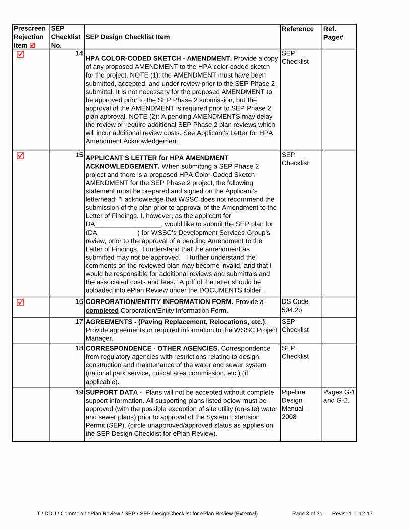
14HPA COLOR-CODED SKETCH - AMENDMENT. Provide a copy of any proposed AMENDMENT to the HPA color-coded sketch for the project. NOTE (1): the AMENDMENT must have been submitted, accepted, and under review prior to the SEP Phase 2 submittal. It is not necessary for the proposed AMENDMENT to be approved prior to the SEP Phase 2 submission, but the approval of the AMENDMENT is required prior to SEP Phase 2 plan approval. NOTE (2): A pending AMENDMENTS may delay the review or require additional SEP Phase 2 plan reviews which will incur additional review costs. See Applicant's Letter for HPA Amendment Acknowledgement.
SEP Checklist
15 APPLICANT'S LETTER for HPA AMENDMENT ACKNOWLEDGEMENT. When submitting a SEP Phase 2 project and there is a proposed HPA Color-Coded Sketch AMENDMENT for the SEP Phase 2 project, the following statement must be prepared and signed on the Applicant's letterhead: "I acknowledge that WSSC does not recommend the submission of the plan prior to approval of the Amendment to the Letter of Findings. I, however, as the applicant for DA__________________, would like to submit the SEP plan for (DA___________) for WSSC’s Development Services Group’s review, prior to the approval of a pending Amendment to the Letter of Findings. I understand that the amendment as submitted may not be approved. I further understand the comments on the reviewed plan may become invalid, and that I would be responsible for additional reviews and submittals and the associated costs and fees." A pdf of the letter should be uploaded into ePlan Review under the DOCUMENTS folder.
SEP Checklist
16 CORPORATION/ENTITY INFORMATION FORM. Provide a completed Corporation/Entity Information Form.
DS Code 504.2p
17 AGREEMENTS - (Paving Replacement, Relocations, etc.). Provide agreements or required information to the WSSC Project Manager.
SEP Checklist
18 CORRESPONDENCE - OTHER AGENCIES. Correspondence from regulatory agencies with restrictions relating to design, construction and maintenance of the water and sewer system (national park service, critical area commission, etc.) (if applicable).
SEP Checklist
19 SUPPORT DATA - Plans will not be accepted without complete support information. All supporting plans listed below must be approved (with the possible exception of site utility (on-site) water and sewer plans) prior to approval of the System Extension Permit (SEP). (circle unapproved/approved status as applies on the SEP Design Checklist for ePlan Review).
Pipeline Design Manual - 2008
Pages G-1 and G-2.

T / DDU / Common / ePlan Review / SEP / SEP DesignChecklist for ePlan Review (External) Page 4 of 31 Revised 1-12-17
Prescreen Rejection Item
SEP Checklist No.
SEP Design Checklist ItemReference Ref.
Page#
20 SUPPORT DATA - STORM DRAIN PLANS. STORMWATER MANAGEMENT PLANS and/or ENVIRONMENTAL SITE DESIGN (ESD) PLANS. Provide a copy of the Approved Storm Drain and Paving Plans, Stormwater Management Plans and/or ESD Plans (showing all proposed storm drainage piping and stormwater management control devices including Micro Bioretention, BioFiltration Ponds, Rain Gardens, Infiltration Trenches, etc.). NOTE (1): If plans are not yet approved by County, the unapproved plans are acceptable at time of submittal. NOTE (2): The APPROVED plans are REQUIRED before the SEP plan can be signed, therefore additional SEP Phase 2 plan reviews may be required which will incur additional review costs. NOTE (3): Always submit the first sheet, then provide only the specific sheet(s) of plan and profile applicable for the project. It is not necessary to submit all sheets of the plan.
DS Code 504.2i & j
Page 37
21 SUPPORT DATA - STREET GRADES. Provide a copy of the Approved street grades for proposed public streets. NOTE (1): If plan is not yet approved by county, the unapproved plan is acceptable at submittal time. NOTE (2): The APPROVED plan is REQUIRED before the SEP plan can be signed, therefore additional SEP Phase 2 plan reviews may be required which will incur additional review costs.
DS Code
22 SUPPORT DATA - SEDIMENT CONTROL PLAN. Provide a copy of the Approved sediment control plans. NOTE (1): If plan is not yet approved by county, the unapproved plan is acceptable at submittal time. NOTE (2): The APPROVED plan is REQUIRED before the SEP plan can be signed, therefore additional SEP Phase 2 plan reviews may be required which will incur additional review costs. NOTE (3): All sediment control plan reviews will be electronic. Do NOT submit a separate sediment control plan package to the Environmental Group. The Sediment Control Sticker will be provided directly to the WSSC Project Manager. NOTE (4): Always submit the first sheet, then provide only the specific sheet(s) of plan and profile applicable for the project. It is not necessary to submit all sheets of the plan.
DS Code 504.2j
Page 37
23 EROSION AND SEDIMENT CONTROL PERMIT APPLICATION - Major (E&S). Effective 1-13-2014, provide the application for Erosion and Sediment Control Permit for Major Utility Construction. Complete the top portion of the permit application. NOTE: The E&S Permit Application is not required for State (including University of Maryland) or Federal property or County Public Works projects in Montgomery or Prince George's Counties.
SEP Checklist
24 SUPPORT DATA - RECORDED PLAT. Provide a copy of recorded plat(s). If unavailable at submittal time, provide a copy of proposed plat(s).
DS Code 504.2h
Page 37
25 SUPPORT DATA - MNCPPC PRELIMINARY PLAN. Provide a copy of the MNCPPC Preliminary Plan or Detailed Site Plan. NOTE: Will not be available for previously recorded residential properties.
DS Code 504.2h
Page 37
T / DDU / Common / ePlan Review / SEP / SEP DesignChecklist for ePlan Review (External) Page 5 of 31 Revised 1-12-17
Prescreen Rejection Item
SEP Checklist No.
SEP Design Checklist ItemReference Ref.
Page#
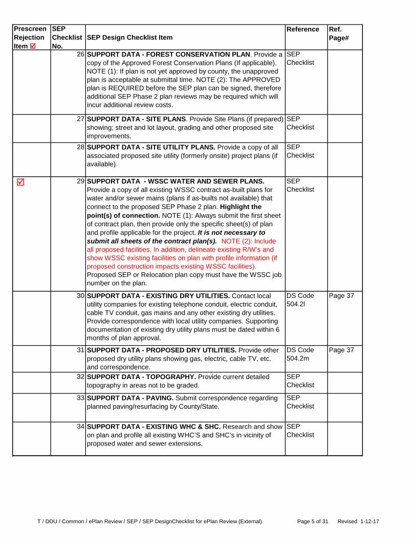
26 SUPPORT DATA - FOREST CONSERVATION PLAN. Provide a copy of the Approved Forest Conservation Plans (If applicable). NOTE (1): If plan is not yet approved by county, the unapproved plan is acceptable at submittal time. NOTE (2): The APPROVED plan is REQUIRED before the SEP plan can be signed, therefore additional SEP Phase 2 plan reviews may be required which will incur additional review costs.
SEP Checklist
27 SUPPORT DATA - SITE PLANS. Provide Site Plans (if prepared) showing; street and lot layout, grading and other proposed site improvements.
SEP Checklist
28 SUPPORT DATA - SITE UTILITY PLANS. Provide a copy of all associated proposed site utility (formerly onsite) project plans (if available).
SEP Checklist
29 SUPPORT DATA - WSSC WATER AND SEWER PLANS. Provide a copy of all existing WSSC contract as-built plans for water and/or sewer mains (plans if as-builts not available) that connect to the proposed SEP Phase 2 plan. Highlight the point(s) of connection. NOTE (1): Always submit the first sheet of contract plan, then provide only the specific sheet(s) of plan and profile applicable for the project. It is not necessary to submit all sheets of the contract plan(s). NOTE (2): Include all proposed facilities. In addition, delineate existing R/W's and show WSSC existing facilities on plan with profile information (if proposed construction impacts existing WSSC facilities). Proposed SEP or Relocation plan copy must have the WSSC job number on the plan.
SEP Checklist
30 SUPPORT DATA - EXISTING DRY UTILITIES. Contact local utility companies for existing telephone conduit, electric conduit, cable TV conduit, gas mains and any other existing dry utilities. Provide correspondence with local utility companies. Supporting documentation of existing dry utility plans must be dated within 6 months of plan approval.
DS Code 504.2l
Page 37
31 SUPPORT DATA - PROPOSED DRY UTILITIES. Provide other proposed dry utility plans showing gas, electric, cable TV, etc. and correspondence.
DS Code 504.2m
Page 37
32 SUPPORT DATA - TOPOGRAPHY. Provide current detailed topography in areas not to be graded.
SEP Checklist
33 SUPPORT DATA - PAVING. Submit correspondence regarding planned paving/resurfacing by County/State.
SEP Checklist
34 SUPPORT DATA - EXISTING WHC & SHC. Research and show on plan and profile all existing WHC’S and SHC’s in vicinity of proposed water and sewer extensions.
SEP Checklist
T / DDU / Common / ePlan Review / SEP / SEP DesignChecklist for ePlan Review (External) Page 6 of 31 Revised 1-12-17
Prescreen Rejection Item
SEP Checklist No.
SEP Design Checklist ItemReference Ref.
Page#
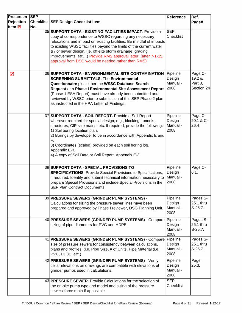
35 SUPPORT DATA - EXISTING FACILITIES IMPACT. Provide a copy of correspondence to WSSC regarding any necessary relocations and impact on existing facilities. Be mindful of impacts to existing WSSC facilities beyond the limits of the current water & / or sewer design. (ie. off-site storm drainage, grading improvements, etc…) Provide RMS approval letter. (after 7-1-15, approval from DSG would be needed rather than RMS)
SEP Checklist
36 SUPPORT DATA - ENVIRONMENTAL SITE CONTAMINATION SCREENING SUBMITTALS. The Environmental Questionnaire plus either the WSSC Database Search Request or a Phase I Environmental Site Assessment Report (Phase 1 ESA Report) must have already been submitted and reviewed by WSSC prior to submission of this SEP Phase 2 plan as instructed in the HPA Letter of Findings.
Pipeline Design Manual - 2008
Page C-19.2 & Part 3, Section 24
37 SUPPORT DATA - SOIL REPORT. Provide a Soil Report wherever required for special design; e.g., blocking, tunnels, structures, CIP size mains, etc. If required, provide the following:1) Soil boring location plan.2) Borings by developer to be in accordance with Appendix E and F.3) Coordinates (scaled) provided on each soil boring log. Appendix E-3.4) A copy of Soil Data or Soil Report. Appendix E-3.
Pipeline Design Manual - 2008
Page C-20.1 & C-26.4
38 SUPPORT DATA - SPECIAL PROVISIONS TO SPECIFICATIONS. Provide Special Provisions to Specifications, if required. Identify and submit technical information necessary to prepare Special Provisions and include Special Provisions in the SEP Plan Contract Documents.
Pipeline Design Manual - 2008
Page C-6.1.
39 PRESSURE SEWERS (GRINDER PUMP SYSTEMS) - Calculations for sizing the pressure sewer lines have been prepared and approved by Phase I reviewer, DSG Planning Unit.
Pipeline Design Manual - 2008
Pages S-25.1 thru S-25.7.
40 PRESSURE SEWERS (GRINDER PUMP SYSTEMS) - Compare sizing of pipe diameters for PVC and HDPE.
Pipeline Design Manual - 2008
Pages S-25.1 thru S-25.7.
41 PRESSURE SEWERS (GRINDER PUMP SYSTEMS) - Compare size of pressure sewers for consistency between calculations, plans and profiles. (i.e. Pipe Size, # of Units, Pipe Material (i.e. PVC, HD8E, etc.)
Pipeline Design Manual - 2008
Pages S-25.1 thru S-25.7.
42 PRESSURE SEWERS (GRINDER PUMP SYSTEMS) - Verify cellar elevations on drawings are compatible with elevations of grinder pumps used in calculations.
Pipeline Design Manual - 2008
Page 25.3.
43 PRESSURE SEWER. Provide Calculations for the selection of the on-site pump type and model and sizing of the pressure sewer / force main if applicable.
SEP Checklist

T / DDU / Common / ePlan Review / SEP / SEP DesignChecklist for ePlan Review (External) Page 7 of 31 Revised 1-12-17
Prescreen Rejection Item
SEP Checklist No.
SEP Design Checklist ItemReference Ref.
Page#
44 PERMIT NUMBERS for SEP PLANS - Effective 11-21-16 all permit numbers for service connections or abandonments must be applied for electronically through the new ePermitting system. (Applicable ONLY for SEP plans with service connection and/or abandonment work performed under the SEP plan.). All permit numbers must be on the SEP plans for Prescreen Review. A separate permit application must be completed and submitted via ePermitting for each permit number required for a water and/or sewer service connection (pair) to a property shown on the SEP plan. Select permit type 'SEP Use Only' for all permit numbers required for the SEP plan (This includes SEP Applicant Owned Properties as well as Non-Applicant Property Service Connections). Be sure to indicate the correct SEP Job/Contract Number on each permit application when applying through the ePermitting system. Contact Permit Services Unit with questions.
DS Code 504.2c
Page 35
45 NON-APPLICANT PROPERTY SERVICE CONNECTION(S). An abutting ‘non-applicant’ property is defined as a property belonging to owners other than SEP applicant, which abut the proposed main. Use permit type 'SEP Plan Use Only' for permit number(s) for these non-applicant properties. Please ensure to attach a location form when applying via ePermitting for any Non-Applicant Property Service Connection(s) abutting the proposed mainline extension. Payment for the Abutting Non-Applicant Property Service Connection(s) is required when invoiced (cash/check, deferred payment option, SEP Applicant Payment Voucher).
SEP Checklist
47 SDC CREDIT/REIMBURSEMENT QUALIFIED PROJECT REQUEST. Request to design and construct a Qualified Project. For CIP size lines only.
DS Code 1202.1
Page 105
48 PLAN VIEWS - GENERAL. Approval date and number (SCD) shown for developer’s sediment control in General Notes.
SEP Checklist
49GENERAL NOTES and SEP NOTES. Refer to WSSC Base Template (WSSC-DSG.dwt).
WSSC Base Sheet Template
50 JOB TITLE BLOCK. 1st line - election district, 2nd line – project description, 3rd line – street names, 4th line – subdivision name and part number (as applicable). Refer to WSSC Base Template (WSSC-DSG.dwt)
WSSC Base Sheet Template
51 VICINITY MAP. 1-inch = 2000 FT scale. Show layout of streets clearly sufficient for contractor's access; show locator map, current ADC map page and grid number. (Indicate job number on map). Refer to WSSC Base Template (WSSC-DSG.dwt).
WSSC Base Sheet Template
52 SEP PROJECT NUMBER. Provide the Project Number (e.g. DA1234B02) often referred to as the SEP or job number on all plan sheets. Refer to WSSC Base Template (WSSC-DSG.dwt).
WSSC Base Sheet Template

T / DDU / Common / ePlan Review / SEP / SEP DesignChecklist for ePlan Review (External) Page 8 of 31 Revised 1-12-17
Prescreen Rejection Item
SEP Checklist No.
SEP Design Checklist ItemReference Ref.
Page#
53 CIP PROJECT NUMBER. Provide CIP Project Number (e.g., sewer project S-75.01, water project W-80.08). Locate over title block. Check status (active, dependent, etc.) and advise DPM. Refer to WSSC Base Template (WSSC-DSG.dwt).
WSSC Base Sheet Template
54 TOWN NOTIFICATION. Provide details of town notification. Refer to WSSC Base Template (WSSC-DSG.dwt).
WSSC Base Sheet Template
55 AS-BUILT DATA. Provide As-Built data as appropriate. Refer to WSSC Base Template (WSSC-DSG.dwt).
WSSC Base Sheet Template
56 DRAWING INDEX. Provide drawing index. Refer to WSSC Base Template (WSSC-DSG.dwt).
WSSC Base Sheet Template
58 GRAPHIC SCALES. Provide Graphic Scales on all sheets. Plan: horizontal 1-inch = 30 feet (preferred) or 1-inch = 50 feet. Profile: 1-inch = 10 feet (vertical) and 1-inch = 100 feet (horizontal). Profiles must be drawn in same direction as plan view. The use of the following plan and profile scales is acceptable in some cases where the level of detail on the plan would be difficult to read at the scales listed above: Plan: 1-inch = 20 feet (horizontal). Profile: 1” = 5’ (vertical) and 1” = 50 feet (horizontal). Refer to WSSC Base Template (WSSC-DSG.dwt).
Pipeline Design
Manual - 2008
Page G-1.
59 NORTH ARROW WITH DATUM. The north arrow (generally pointing to top of sheets) with required MD State Plane horizontal datum (NAD 83/91) and vertical datum (NGVD 1929) survey reference shown on each plan view. Refer to WSSC Base Template (WSSC-DSG.dwt).
Pipeline Design Manual - 2008
Appendix D-1
60 ENGINEERING FIRM BLOCK. List contact name and contact email address. Refer to WSSC Base Template (WSSC-DSG.dwt).
WSSC Base Sheet Template
61 APPLICANT/DEVELOPER NAME BLOCK. List contact name and contact email address. Refer to WSSC Base Template (WSSC-DSG.dwt).
WSSC Base Sheet Template
62 MINI-BASIN and DRAINAGE BASIN. Provide drainage basin name (over title block) and mini-basin number(s) from Letter of Findings. Refer to WSSC Base Template (WSSC-DSG.dwt).
WSSC Base Sheet Template
63 SERVICE CATEGORY. Provide Service Categories. Refer to WSSC Base Template (WSSC-DSG.dwt)..
WSSC Base Sheet Template
64 STREET NAMES. Show on EACH sheet (plan and profile). Include SHA Route No. Add notation (Private Street) to private street name label. (Streets/Alleys need to be labeled for reference in provided profiles and in DSG’s response. Temporary names like “A, B, C’ etc. are acceptable if real names have not yet been established – alleys may not need labeled if reference wouldn’t be needed.) Note: All street names must MATCH to Address Assignment/Verification Documentation approved by MNCPPC.
SEP Checklist
T / DDU / Common / ePlan Review / SEP / SEP DesignChecklist for ePlan Review (External) Page 9 of 31 Revised 1-12-17
Prescreen Rejection Item
SEP Checklist No.
SEP Design Checklist ItemReference Ref.
Page#
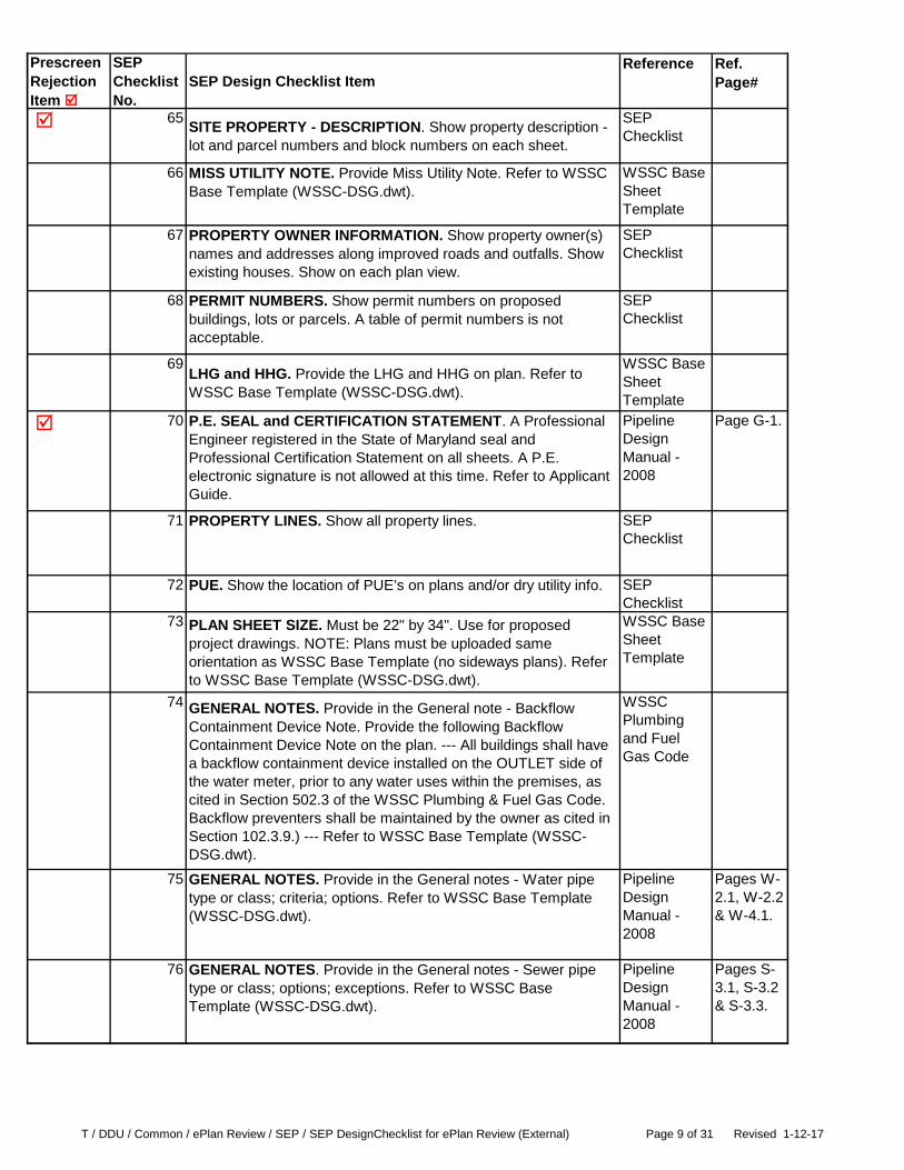
65 SITE PROPERTY - DESCRIPTION. Show property description - lot and parcel numbers and block numbers on each sheet.
SEP Checklist
66 MISS UTILITY NOTE. Provide Miss Utility Note. Refer to WSSC Base Template (WSSC-DSG.dwt).
WSSC Base Sheet Template
67 PROPERTY OWNER INFORMATION. Show property owner(s) names and addresses along improved roads and outfalls. Show existing houses. Show on each plan view.
SEP Checklist
68 PERMIT NUMBERS. Show permit numbers on proposed buildings, lots or parcels. A table of permit numbers is not acceptable.
SEP Checklist
69LHG and HHG. Provide the LHG and HHG on plan. Refer to WSSC Base Template (WSSC-DSG.dwt).
WSSC Base Sheet Template
70 P.E. SEAL and CERTIFICATION STATEMENT. A Professional Engineer registered in the State of Maryland seal and Professional Certification Statement on all sheets. A P.E. electronic signature is not allowed at this time. Refer to Applicant Guide.
Pipeline Design Manual - 2008
Page G-1.
71 PROPERTY LINES. Show all property lines. SEP Checklist
72 PUE. Show the location of PUE’s on plans and/or dry utility info. SEP Checklist
73 PLAN SHEET SIZE. Must be 22" by 34". Use for proposed project drawings. NOTE: Plans must be uploaded same orientation as WSSC Base Template (no sideways plans). Refer to WSSC Base Template (WSSC-DSG.dwt).
WSSC Base Sheet Template
74 GENERAL NOTES. Provide in the General note - Backflow Containment Device Note. Provide the following Backflow Containment Device Note on the plan. --- All buildings shall have a backflow containment device installed on the OUTLET side of the water meter, prior to any water uses within the premises, as cited in Section 502.3 of the WSSC Plumbing & Fuel Gas Code. Backflow preventers shall be maintained by the owner as cited in Section 102.3.9.) --- Refer to WSSC Base Template (WSSC-DSG.dwt).
WSSC Plumbing and Fuel Gas Code
75 GENERAL NOTES. Provide in the General notes - Water pipe type or class; criteria; options. Refer to WSSC Base Template (WSSC-DSG.dwt).
Pipeline Design Manual - 2008
Pages W-2.1, W-2.2 & W-4.1.
76 GENERAL NOTES. Provide in the General notes - Sewer pipe type or class; options; exceptions. Refer to WSSC Base Template (WSSC-DSG.dwt).
Pipeline Design Manual - 2008
Pages S-3.1, S-3.2 & S-3.3.
T / DDU / Common / ePlan Review / SEP / SEP DesignChecklist for ePlan Review (External) Page 10 of 31 Revised 1-12-17
Prescreen Rejection Item
SEP Checklist No.
SEP Design Checklist ItemReference Ref.
Page#
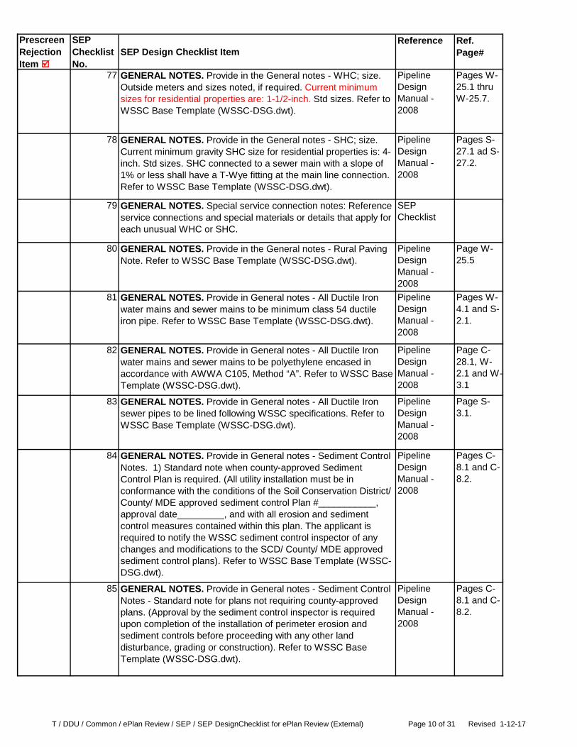
77 GENERAL NOTES. Provide in the General notes - WHC; size. Outside meters and sizes noted, if required. Current minimum sizes for residential properties are: 1-1/2-inch. Std sizes. Refer to WSSC Base Template (WSSC-DSG.dwt).
Pipeline Design Manual - 2008
Pages W-25.1 thru W-25.7.
78 GENERAL NOTES. Provide in the General notes - SHC; size. Current minimum gravity SHC size for residential properties is: 4-inch. Std sizes. SHC connected to a sewer main with a slope of 1% or less shall have a T-Wye fitting at the main line connection. Refer to WSSC Base Template (WSSC-DSG.dwt).
Pipeline Design Manual - 2008
Pages S-27.1 ad S-27.2.
79 GENERAL NOTES. Special service connection notes: Reference service connections and special materials or details that apply for each unusual WHC or SHC.
SEP Checklist
80 GENERAL NOTES. Provide in the General notes - Rural Paving Note. Refer to WSSC Base Template (WSSC-DSG.dwt).
Pipeline Design Manual - 2008
Page W-25.5
81 GENERAL NOTES. Provide in General notes - All Ductile Iron water mains and sewer mains to be minimum class 54 ductile iron pipe. Refer to WSSC Base Template (WSSC-DSG.dwt).
Pipeline Design Manual - 2008
Pages W-4.1 and S-2.1.
82 GENERAL NOTES. Provide in General notes - All Ductile Iron water mains and sewer mains to be polyethylene encased in accordance with AWWA C105, Method “A”. Refer to WSSC Base Template (WSSC-DSG.dwt).
Pipeline Design Manual - 2008
Page C-28.1, W-2.1 and W-3.1
83 GENERAL NOTES. Provide in General notes - All Ductile Iron sewer pipes to be lined following WSSC specifications. Refer to WSSC Base Template (WSSC-DSG.dwt).
Pipeline Design Manual - 2008
Page S-3.1.
84 GENERAL NOTES. Provide in General notes - Sediment Control Notes. 1) Standard note when county-approved Sediment Control Plan is required. (All utility installation must be in conformance with the conditions of the Soil Conservation District/ County/ MDE approved sediment control Plan #___________, approval date_________, and with all erosion and sediment control measures contained within this plan. The applicant is required to notify the WSSC sediment control inspector of any changes and modifications to the SCD/ County/ MDE approved sediment control plans). Refer to WSSC Base Template (WSSC-DSG.dwt).
Pipeline Design Manual - 2008
Pages C-8.1 and C-8.2.
85 GENERAL NOTES. Provide in General notes - Sediment Control Notes - Standard note for plans not requiring county-approved plans. (Approval by the sediment control inspector is required upon completion of the installation of perimeter erosion and sediment controls before proceeding with any other land disturbance, grading or construction). Refer to WSSC Base Template (WSSC-DSG.dwt).
Pipeline Design Manual - 2008
Pages C-8.1 and C-8.2.

T / DDU / Common / ePlan Review / SEP / SEP DesignChecklist for ePlan Review (External) Page 11 of 31 Revised 1-12-17
Prescreen Rejection Item
SEP Checklist No.
SEP Design Checklist ItemReference Ref.
Page#
86 GENERAL NOTES. Provide in General notes - Sediment Control Notes - Additional notes for areas of existing paving: (Roadway must be kept broom swept at all times.) Refer to WSSC Base Template (WSSC-DSG.dwt).
Pipeline Design Manual - 2008
Pages C-8.1 and C-8.2.
87 GENERAL NOTES. Provide in General notes - WHC curb stop location specified where not on property line. WHC and SHC termination location must be specified if either termination is not on the property line or if termination does not meet standard (on the property line or the WSSC right of way line, whichever is closer to the pipeline). Also justification for the non-standard setting must be included. Refer to WSSC Base Template (WSSC-DSG.dwt).
Pipeline Design Manual - 2008
Pages W-25.1 thru W-25.8.
88 GENERAL NOTES. Provide in General notes - Include pressure reducing valve/booster pump note from the Letter of Findings (from LOF). Refer to WSSC Base Template (WSSC-DSG.dwt).
WSSC Base Sheet Template
89 GENERAL NOTES. Provide in General notes - Notification required when construction is within town or city limits. Refer to WSSC Base Template (WSSC-DSG.dwt).
WSSC Base Sheet Template
90 GENERAL NOTES. Provide in General notes Pressure sewer service connections with lot # note. Refer to WSSC Base Template (WSSC-DSG.dwt).
WSSC Base Sheet Template
91 GENERAL NOTES. Additional special SHC connection notes: Grinder Pump required for lots; Ejector pump required for lots (or service available to first floor, etc.) Refer to WSSC Base Template (WSSC-DSG.dwt).
WSSC Base Sheet Template
92 GENERAL NOTES. Special design conditions (deep manholes, C900 or profile pipe, etc) if applicable
WSSC Base Sheet Template
93 SEP NOTES. Provide SEP note. Notify the WSSC contract manager at (301) 206-XXXX* and sediment control specialist at (301) 206-8077, a minimum of 72 hours in advance, to coordinate a preconstruction meeting prior to commencement of the work. The utility sediment control permit will be issued to the applicant or his or her contractor at this meeting.XXXX* should be replaced with the appropriate extension:Southern Zone – 7316Western Zone – 7339Northern Zone – 7363Central Zone – 4308 Refer to WSSC Base Template (WSSC-DSG.dwt).
WSSC Base Sheet Template
94 SEP NOTES. Provide SEP note - All work performed under this contract shall be done in accordance with approved drawings and specifications as defined in the System Extension Permit. Refer to WSSC Base Template (WSSC-DSG.dwt).
WSSC Base Sheet Template
95 SEP NOTES. Provide SEP note - All work to be performed by the applicant’s contractor under the supervision and inspection of the Systems Inspection Group at no cost to WSSC. Refer to WSSC Base Template (WSSC-DSG.dwt).
WSSC Base Sheet Template
T / DDU / Common / ePlan Review / SEP / SEP DesignChecklist for ePlan Review (External) Page 12 of 31 Revised 1-12-17
Prescreen Rejection Item
SEP Checklist No.
SEP Design Checklist ItemReference Ref.
Page#
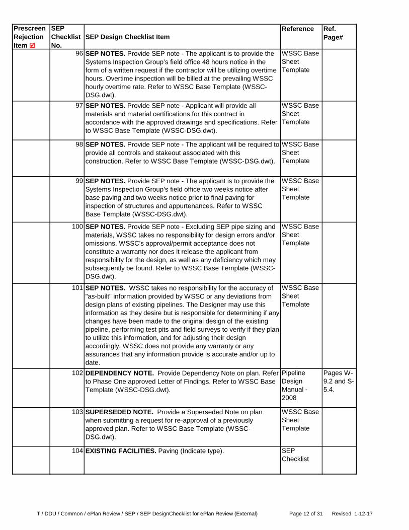
96 SEP NOTES. Provide SEP note - The applicant is to provide the Systems Inspection Group’s field office 48 hours notice in the form of a written request if the contractor will be utilizing overtime hours. Overtime inspection will be billed at the prevailing WSSC hourly overtime rate. Refer to WSSC Base Template (WSSC-DSG.dwt).
WSSC Base Sheet Template
97 SEP NOTES. Provide SEP note - Applicant will provide all materials and material certifications for this contract in accordance with the approved drawings and specifications. Refer to WSSC Base Template (WSSC-DSG.dwt).
WSSC Base Sheet Template
98 SEP NOTES. Provide SEP note - The applicant will be required to provide all controls and stakeout associated with this construction. Refer to WSSC Base Template (WSSC-DSG.dwt).
WSSC Base Sheet Template
99 SEP NOTES. Provide SEP note - The applicant is to provide the Systems Inspection Group’s field office two weeks notice after base paving and two weeks notice prior to final paving for inspection of structures and appurtenances. Refer to WSSC Base Template (WSSC-DSG.dwt).
WSSC Base Sheet Template
100 SEP NOTES. Provide SEP note - Excluding SEP pipe sizing and materials, WSSC takes no responsibility for design errors and/or omissions. WSSC's approval/permit acceptance does not constitute a warranty nor does it release the applicant from responsibility for the design, as well as any deficiency which may subsequently be found. Refer to WSSC Base Template (WSSC-DSG.dwt).
WSSC Base Sheet Template
101 SEP NOTES. WSSC takes no responsibility for the accuracy of "as-built" information provided by WSSC or any deviations from design plans of existing pipelines. The Designer may use this information as they desire but is responsible for determining if any changes have been made to the original design of the existing pipeline, performing test pits and field surveys to verify if they plan to utilize this information, and for adjusting their design accordingly. WSSC does not provide any warranty or any assurances that any information provide is accurate and/or up to date.
WSSC Base Sheet Template
102 DEPENDENCY NOTE. Provide Dependency Note on plan. Refer to Phase One approved Letter of Findings. Refer to WSSC Base Template (WSSC-DSG.dwt).
Pipeline Design Manual - 2008
Pages W-9.2 and S-5.4.
103 SUPERSEDED NOTE. Provide a Superseded Note on plan when submitting a request for re-approval of a previously approved plan. Refer to WSSC Base Template (WSSC-DSG.dwt).
WSSC Base Sheet Template
104 EXISTING FACILITIES. Paving (Indicate type). SEP Checklist
T / DDU / Common / ePlan Review / SEP / SEP DesignChecklist for ePlan Review (External) Page 13 of 31 Revised 1-12-17
Prescreen Rejection Item
SEP Checklist No.
SEP Design Checklist ItemReference Ref.
Page#
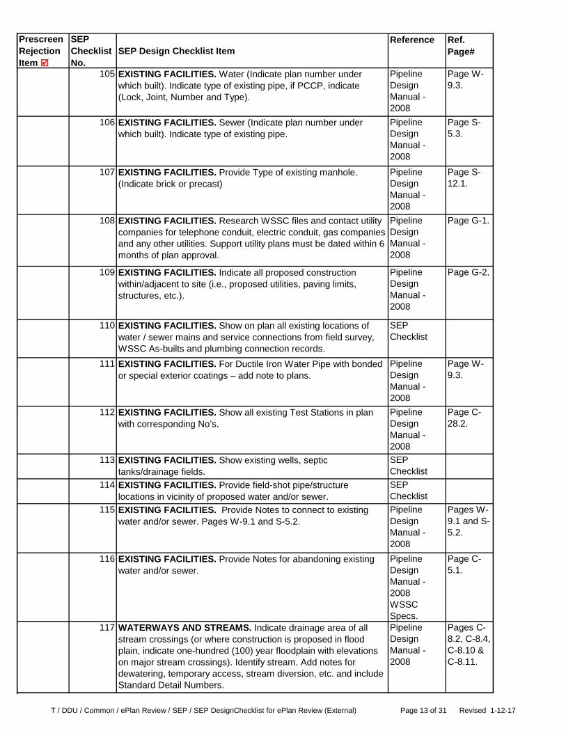
105 EXISTING FACILITIES. Water (Indicate plan number under which built). Indicate type of existing pipe, if PCCP, indicate (Lock, Joint, Number and Type).
Pipeline Design Manual - 2008
Page W-9.3.
106 EXISTING FACILITIES. Sewer (Indicate plan number under which built). Indicate type of existing pipe.
Pipeline Design Manual - 2008
Page S-5.3.
107 EXISTING FACILITIES. Provide Type of existing manhole. (Indicate brick or precast)
Pipeline Design Manual - 2008
Page S-12.1.
108 EXISTING FACILITIES. Research WSSC files and contact utility companies for telephone conduit, electric conduit, gas companies and any other utilities. Support utility plans must be dated within 6 months of plan approval.
Pipeline Design Manual - 2008
Page G-1.
109 EXISTING FACILITIES. Indicate all proposed construction within/adjacent to site (i.e., proposed utilities, paving limits, structures, etc.).
Pipeline Design Manual - 2008
Page G-2.
110 EXISTING FACILITIES. Show on plan all existing locations of water / sewer mains and service connections from field survey, WSSC As-builts and plumbing connection records.
SEP Checklist
111 EXISTING FACILITIES. For Ductile Iron Water Pipe with bonded or special exterior coatings – add note to plans.
Pipeline Design Manual - 2008
Page W-9.3.
112 EXISTING FACILITIES. Show all existing Test Stations in plan with corresponding No’s.
Pipeline Design Manual - 2008
Page C-28.2.
113 EXISTING FACILITIES. Show existing wells, septic tanks/drainage fields.
SEP Checklist
114 EXISTING FACILITIES. Provide field-shot pipe/structure locations in vicinity of proposed water and/or sewer.
SEP Checklist
115 EXISTING FACILITIES. Provide Notes to connect to existing water and/or sewer. Pages W-9.1 and S-5.2.
Pipeline Design Manual - 2008
Pages W-9.1 and S-5.2.
116 EXISTING FACILITIES. Provide Notes for abandoning existing water and/or sewer.
Pipeline Design Manual - 2008WSSC Specs.
Page C-5.1.
117 WATERWAYS AND STREAMS. Indicate drainage area of all stream crossings (or where construction is proposed in flood plain, indicate one-hundred (100) year floodplain with elevations on major stream crossings). Identify stream. Add notes for dewatering, temporary access, stream diversion, etc. and include Standard Detail Numbers.
Pipeline Design Manual - 2008
Pages C-8.2, C-8.4, C-8.10 & C-8.11.

T / DDU / Common / ePlan Review / SEP / SEP DesignChecklist for ePlan Review (External) Page 14 of 31 Revised 1-12-17
Prescreen Rejection Item
SEP Checklist No.
SEP Design Checklist ItemReference Ref.
Page#
118 WATERWAYS AND STREAMS. For any water body within one-hundred (100) feet of construction area, indicate wetland boundaries and one-hundred (100) year flood plain with elevations.
Pipeline Design Manual - 2008
Page C-8.2.
119 WATERWAYS AND STREAMS. For all existing or proposed stream/ditch crossings, show top of bank, bottom of bank, field inverts of stream/ditch on Profile.
Pipeline Design Manual - 2008
Page W-11.1 and S-8.3
120 WATERWAYS AND STREAMS. Ungrouted riprap shown on plan view with proper symbols and notes.
Standard Detail SC/3.0Pipeline Design Manual - 2008
Page C-9.4.
121 RESTORATION. Restoration Schedule completed. SEP Specs Sections 02315 III.2.B and 02920, 1.2.A.
122 ENVIRONMENTAL. All existing Sediment Control Devices (SCD) shown on plans.
Pipeline Design Manual - 2008
Page C-8.4.
123 ENVIRONMENTAL. No water and sewer alignments within fifty (50) feet of sediment control traps (draining ten (10) acres or more), basins or water retention ponds. Alignments within fifty (50) feet shall be approved by WSSC on a case by case basis.
SEP Checklist
124 ENVIRONMENTAL. Approval date and number (SCD) shown for developer’s sediment control in General Notes.
Pipeline Design Manual - 2008
Page C-8.4.
125 ENVIRONMENTAL. Show all sediment controls to be installed by contractor and reference by symbols (SCE, SF, SSF, etc.)
Pipeline Design Manual - 2008
Pages C-8.4 thru C-8.12.
126 ENVIRONMENTAL. Show 100 year flood plain delineation on major stream crossings. Identify stream (if a named tributary).
SEP Checklist
127 ENVIRONMENTAL. Show existing contours at five (5) foot or less intervals, in outfalls and flood plains, for a distance of one hundred (100) feet either side of pipe centerline.
SEP Checklist
128 ENVIRONMENTAL. Show drainage area at stream crossings or where construction is shown in flood plain.
Pipeline Design Manual - 2008
Page C-8.4
129 ENVIRONMENTAL. Show all wooded area (delineation). SEP Checklist

T / DDU / Common / ePlan Review / SEP / SEP DesignChecklist for ePlan Review (External) Page 15 of 31 Revised 1-12-17
Prescreen Rejection Item
SEP Checklist No.
SEP Design Checklist ItemReference Ref.
Page#
130 ENVIRONMENTAL. Show individual trees 6-inch and larger within fifty (50) feet of work area limits. Label size & type.
Pipeline Design Manual - 2008
Page C-8.12.
131 ENVIRONMENTAL. Show wetland boundaries and twenty-five (25) foot buffer delineation. One hundred (100) foot buffer where applicable.
Pipeline Design Manual - 2008
Page C-23.1.
132 ENVIRONMENTAL. Show Chesapeake Bay Critical Areas boundaries (delineation).
SEP Checklist
133 ENVIRONMENTAL. Show “Tree Save Areas” in vicinity of water and sewer lines in developments.
Pipeline Design Manual - 2008
Page C-8.12.
134 ENVIRONMENTAL. Show stabilized construction entrance. Pipeline Design Manual - 2008
Pages C-8.8 & C-8.9.
135 ENVIRONMENTAL. Add notes for dewatering, temporary access, stream diversion, etc.
Pipeline Design Manual - 2008
Pages C-8.10 & C-8.11.
136 ENVIRONMENTAL. Include reference to Drawing SC-1 in drawing index on Sheet 1.
Pipeline Design Manual - 2008
Page C-8.1.
137 PERMITS - OTHER AGENCIES. All agency permit conditions that come out from their review of W&S plans, must be submitted to WSSC at the earliest opportunity.
SEP Checklist
138 PERMITS - OTHER AGENCIES. Railroad. Show location of water and/or sewer crossing railroad right of way with dimension from milepost marker, stationing, etc.
SEP Checklist
139 PERMITS - OTHER AGENCIES. Railroad - Display Pipe Crossing Data.
SEP Checklist
140 PERMITS - OTHER AGENCIES. Railroad - Show non-standard details for method of installation.
SEP Checklist
141 PERMITS - OTHER AGENCIES. Railroad - . Special note for railroad access crossing.
SEP Checklist
142 PERMITS - OTHER AGENCIES. MNCP&PC - Show required work limits/working space.
Pipeline Design Manual - 2008
Page C-2.4.

T / DDU / Common / ePlan Review / SEP / SEP DesignChecklist for ePlan Review (External) Page 16 of 31 Revised 1-12-17
Prescreen Rejection Item
SEP Checklist No.
SEP Design Checklist ItemReference Ref.
Page#
143 PERMITS - OTHER AGENCIES. Sediment Control sticker issued.
SEP Checklist
144 ALIGNMENT. Minimum separation of ten (10) feet from existing or proposed sewer (OD to OD).
Pipeline Design Manual - 2008
Pages W-8.1 & S-5.1.
145 ALIGNMENT. Minimum separation of five (5) feet from existing or proposed storm drains, inlets, poles, gas mains, conduits, etc.
Pipeline Design Manual - 2008
Pages W-8.1 & S-5.1.
146 CLEARANCE. All mains to be designed with a minimum of fifteen (15) feet clearance (for 12-inch and smaller diameter pipelines) and twenty five (25) feet clearance (for larger than 12-inch diameter pipelines) from proposed or existing buildings and beyond the imaginary 1:1 slope from the bottom of the foundation of the building/dwelling to the edge of the trench.
Pipeline Design Manual - 2008
Page C-3.2
147 CLEARANCE. Required clearances between proposed water and/or sewer systems and other proposed/existing features (buildings, structures, curbs, streams, etc.) have not been provided.
SEP Checklist
148 TUNNEL SOIL. Investigation and Design: Preliminary tunnel submittal. (Natural scale tunnel profiles with details and results of soils investigations).
Pipeline Design Manual - 2008
Pages C-20.1, C-25.1 thru C-25.3, C-26.1 thru Page C-26.4.
149 TUNNEL SOIL. Investigation and Design: WSSC tunnel meeting. (If necessary) If a tunnel meeting is conducted, utilize findings in subsequent design work.
SEP Checklist
150 TUNNEL SOIL. Investigation and Design: Tunnel Geotechnical Report required.(___yes ___no).
Pipeline Design Manual - 2008
Pages C-26.4 and C-26.5.
151 TUNNEL SOIL. Investigation and Design: Evaluation of pipe failure and settlement.
Pipeline Design Manual - 2008
Page C-26.9.
152 TUNNEL SOIL. Investigation and Design:. Water table and dewatering addressed (if necessary).
Pipeline Design Manual - 2008
Page C-26.17.
153 TUNNEL SOIL. Investigation and Design: Environmental concerns addressed (blasting, utilities, water quality, etc.).
SEP Checklist

T / DDU / Common / ePlan Review / SEP / SEP DesignChecklist for ePlan Review (External) Page 17 of 31 Revised 1-12-17
Prescreen Rejection Item
SEP Checklist No.
SEP Design Checklist ItemReference Ref.
Page#
154 TUNNEL SOIL. Investigation and Design: Comply with MSHA and/or railroad authority requirements.
Pipeline Design Manual - 2008
Pages C-25.1 thru C-25.3.
155 TUNNEL SOIL. Investigation and Design: Sufficient construction access.
Pipeline Design Manual - 2008
Pages C-2.4 & C-26.16.
156 TUNNEL SOIL. Investigation and Design: Tunnel Access Manhole for tunnels/casings greater than twenty (20) feet deep.
Pipeline Design Manual - 2008
Page 26.17.
157 TUNNEL SOIL. Investigation and Design: Alternate Design considered, options provided.
Pipeline Design Manual - 2008
Page C-19.1, C-25.1 thru C-25.3.
158 TUNNEL/BORE-JACK. Computations submitted to support the design, as required (non-standard items may require computations).
Pipeline Design Manual - 2008
Page C-26.1 and appendix F.
159 TUNNEL/BORE-JACK. Observation wells as required at tunnel borings.
Pipeline Design Manual - 2008
Page C-26.1 and appendix F.
160 TUNNEL/BORE-JACK. Final Tunnel Geotechnical Report, if required.
Pipeline Design Manual - 2008
Pages C-26.4 & C-26.5.
161 TUNNEL/BORE-JACK. Permit from issuing agency in conformance with design.
Pipeline Design Manual - 2008
Page C-25.1.
162 TUNNEL/BORE-JACK. Concrete encasement / arches and cradles shown on plan and profile.
Pipeline Design Manual - 2008
Pages C-13.1 & C-13.2.
163 TUNNEL/BORE-JACK. Settlement markers required (Min. of two each side of tunnel centerline).
Pipeline Design Manual - 2008(Standard Detail M/7.0 and M/7.1)
Page C-26.18.
164 TUNNEL/BORE-JACK. Special construction requirements for work performed in the vicinity of existing water/sewer mains.
Pipeline Design Manual - 2008
Page C-3.7.

T / DDU / Common / ePlan Review / SEP / SEP DesignChecklist for ePlan Review (External) Page 18 of 31 Revised 1-12-17
Prescreen Rejection Item
SEP Checklist No.
SEP Design Checklist ItemReference Ref.
Page#
165 TUNNEL/BORE-JACK. Corrosion Control measures incorporated.
Pipeline Design Manual - 2008
Page C-28.1.
166 TUNNEL/BORE-JACK. Corrosion Control : Test station numbers provided by WSSC. Total number of test stations indicated on Sheet 1.
Pipeline Design Manual - 2008
Page C-28.2.
167 TUNNEL/BORE-JACK. Corrosion Control: Type of existing corrosion control measures indicated on plan at connections to existing pipe.
Pipeline Design Manual - 2008
Page C-28.6 and W-9.3.
168 TUNNEL/BORE-JACK. Civil Engineering Support Unit approval obtained.
SEP Checklist
169 WSSC EASEMENTS AND CONSTRUCTION STRIPS. Executed (Date: ______________).
Pipeline Design Manual - 2008
Page C-2.1 & Appendix D
170 WSSC EASEMENTS AND CONSTRUCTION STRIPS. Property shown/described.
Pipeline Design Manual - 2008
Page C-2.1 & Appendix D
171 WSSC EASEMENTS AND CONSTRUCTION STRIPS. Property owner’s name shown.
Pipeline Design Manual - 2008
Page C-2.1 & Appendix D
172 WSSC EASEMENTS AND CONSTRUCTION STRIPS. Special commitments.
Pipeline Design Manual - 2008
Page C-2.1 & Appendix D
173 WSSC EASEMENTS AND CONSTRUCTION STRIPS. Offset in right of way, 15-inch sewer and larger (for future relief sewer) - unless difficult and Planning Group approves otherwise.
Pipeline Design Manual - 2008
Page C 2.3.
174 WSSC EASEMENTS AND CONSTRUCTION STRIPS. Show and label existing right of way with liber/folio and width.
Pipeline Design Manual - 2008
Page C-2.1 & Appendix D
175 WSSC EASEMENTS AND CONSTRUCTION STRIPS. Special considerations for existing PCCP water mains.
Pipeline Design Manual - 2008
Page C-2.1.
176 WSSC EASEMENTS AND CONSTRUCTION STRIPS. Provide Additional Easement (right of way) to WSSC for deep sewers.
Pipeline Design Manual - 2008
Page C-2.2.
177 WSSC EASEMENTS AND CONSTRUCTION STRIPS. Right of way required shown in right of way status box (Below signature block).
Pipeline Design Manual - 2008
Page C-2.1 & Appendix D

T / DDU / Common / ePlan Review / SEP / SEP DesignChecklist for ePlan Review (External) Page 19 of 31 Revised 1-12-17
Prescreen Rejection Item
SEP Checklist No.
SEP Design Checklist ItemReference Ref.
Page#
178 SURVEY INFORMATION. Curve data required for 24-inch and larger mains.
Pipeline Design Manual - 2008
Page C-1.2.
179 SURVEY INFORMATION. Required bench marks shown minimum 3 per sheet. (Iron pipes, manholes and fire hydrants not acceptable).
Pipeline Design Manual - 2008
Page C-1.1 & Appendix D
180 SURVEY INFORMATION. Grid coordinates (3 per page). Show at least three (3) coordinates grid tic marks corresponding to MD State Plane horizonal datum (NAD 83/91). Verify orientation with north arrow and all coordinate numbers with each other. Ensure the coordinate numbers meet the following minimum criteria:East – West coordinates are between 1,160,000 - 1,407,000North - South coordinates are between 316,000 - 616,000
SEP Checklist
181 SURVEY INFORMATION. Show distance to nearest existing fire hydrant for testing.
Pipeline Design Manual - 2008
Page W-24.1.
182 SURVEY INFORMATION. Existing valves necessary for shutdown are located.
Pipeline Design Manual - 2008
Page W-18.2.
183 THRUST RESTRAINT. Provide Thrust Restraint Schedule, Form “A”.
Pipeline Design Manual - 2008
Page C-20.1 and Page C-20-Form A-1.
184 THRUST RESTRAINT. Provide Thrust Restraint Calculations. Pipeline Design Manual - 2008
Page C-20.2.
185 CORROSION CONTROL. Provide a complete Corrosion Survey Checklist.
Pipeline Design Manual - 2008
Pages C-20.1 and C-28.10.
186 CORROSION CONTROL. Provide Corrosion Documentation, Form “B”.
Pipeline Design Manual - 2008
Pages C-20.2 and C-28.11.
187 CORROSION CONTROL. Provide Corrosion Control plan and specifications.
Pipeline Design Manual - 2008
Page C-28.2.
188 PLAN VIEWS - WATER. Minimum size 4-inch for mainline water pipelines, minimum size 8-inch with fire hydrants.
Pipeline Design Manual - 2008
Page W-24.2 & Appendix B-5.
189 PLAN VIEWS - WATER. Proposed pipe sizes indicated on plan. Pipeline Design Manual - 2008
Pages W-8.2 and W-11.1.
T / DDU / Common / ePlan Review / SEP / SEP DesignChecklist for ePlan Review (External) Page 20 of 31 Revised 1-12-17
Prescreen Rejection Item
SEP Checklist No.
SEP Design Checklist ItemReference Ref.
Page#
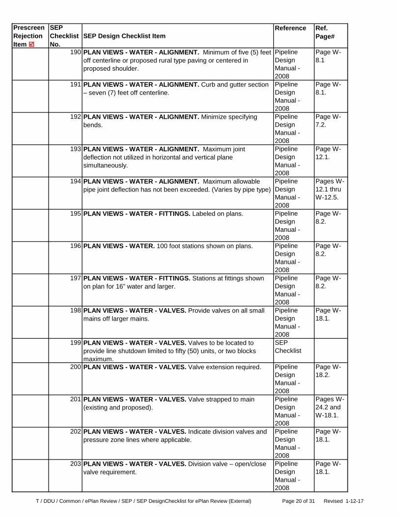
190 PLAN VIEWS - WATER - ALIGNMENT. Minimum of five (5) feet off centerline or proposed rural type paving or centered in proposed shoulder.
Pipeline Design Manual - 2008
Page W-8.1
191 PLAN VIEWS - WATER - ALIGNMENT. Curb and gutter section – seven (7) feet off centerline.
Pipeline Design Manual - 2008
Page W-8.1.
192 PLAN VIEWS - WATER - ALIGNMENT. Minimize specifying bends.
Pipeline Design Manual - 2008
Page W-7.2.
193 PLAN VIEWS - WATER - ALIGNMENT. Maximum joint deflection not utilized in horizontal and vertical plane simultaneously.
Pipeline Design Manual - 2008
Page W-12.1.
194 PLAN VIEWS - WATER - ALIGNMENT. Maximum allowable pipe joint deflection has not been exceeded. (Varies by pipe type)
Pipeline Design Manual - 2008
Pages W-12.1 thru W-12.5.
195 PLAN VIEWS - WATER - FITTINGS. Labeled on plans. Pipeline Design Manual - 2008
Page W-8.2.
196 PLAN VIEWS - WATER. 100 foot stations shown on plans. Pipeline Design Manual - 2008
Page W-8.2.
197 PLAN VIEWS - WATER - FITTINGS. Stations at fittings shown on plan for 16” water and larger.
Pipeline Design Manual - 2008
Page W-8.2.
198 PLAN VIEWS - WATER - VALVES. Provide valves on all small mains off larger mains.
Pipeline Design Manual - 2008
Page W-18.1.
199 PLAN VIEWS - WATER - VALVES. Valves to be located to provide line shutdown limited to fifty (50) units, or two blocks maximum.
SEP Checklist
200 PLAN VIEWS - WATER - VALVES. Valve extension required. Pipeline Design Manual - 2008
Page W-18.2.
201 PLAN VIEWS - WATER - VALVES. Valve strapped to main (existing and proposed).
Pipeline Design Manual - 2008
Pages W-24.2 and W-18.1.
202 PLAN VIEWS - WATER - VALVES. Indicate division valves and pressure zone lines where applicable.
Pipeline Design Manual - 2008
Page W-18.1.
203 PLAN VIEWS - WATER - VALVES. Division valve – open/close valve requirement.
Pipeline Design Manual - 2008
Page W-18.1.

T / DDU / Common / ePlan Review / SEP / SEP DesignChecklist for ePlan Review (External) Page 21 of 31 Revised 1-12-17
Prescreen Rejection Item
SEP Checklist No.
SEP Design Checklist ItemReference Ref.
Page#
204 PLAN VIEWS - WATER - VALVES. Double Valves required (6-inch to 12-inch, laterals from 42-inch and up).
Pipeline Design Manual - 2008
Page W-18.1.
205 PLAN VIEWS - WATER - VALVES. Valves on all fire hydrant leads.
Pipeline Design Manual - 2008
Page W-18.1.
206 PLAN VIEWS - WATER - TAPPING. For DIP and CIP a Tapping Sleeve and Valve is allowed. For PCCP a Tapping Assembly and Valve (TA&V) is not allowed for connecting to existing PCCP water mains. Two sections of PCCP will need to be removed and replaced with Ductile Iron Pipe (DIP) Class 54 and polywrapped in order to connect with a Tee. - Show type of existing pipe - Show Lock Joint Number (if PCCP). Provide connection detail. - Ensure proper tap size. - Ensure sufficient room to make tap.
Pipeline Design Manual - 2008
Pages W-7.3, W-7.4 and W-7.5
207 PLAN VIEWS - WATER - FIRE HYDRANTS. Fire hydrants to be spaced at a maximum of five hundred (500) feet in single family developments; two hundred fifty (250) to three hundred (300) feet in townhouse developments or industrial/commercial. Generally located on lot lines or consistent with proposed driveways, parking bays, etc.
Pipeline Design Manual - 2008
Pages W-24.1 thru W-24.3.
208 PLAN VIEWS - WATER - FIRE HYDRANTS. Elbow elevation and fire hydrant lengths shown.
Pipeline Design Manual - 2008
PageW-24.1.
209 PLAN VIEWS - WATER - FIRE HYDRANTS. Fire Hydrant extensions required. Label correctly (i.e., 8.0’ F.H. w/1.5' extension)
Pipeline Design Manual - 2008
Page W-24.1
210 PLAN VIEWS - WATER - FIRE HYDRANTS. Fire hydrant facing note.
Pipeline Design Manual - 2008
Page W-24.2.
211 PLAN VIEWS - WATER - FIRE HYDRANTS. Salvage note for valves and fire hydrants. Page C-5.1.
Pipeline Design Manual - 2008
Page C-5.1.
212 PLAN VIEWS - WATER - SPECIAL STRUCTURES. Blow-off, Air Valve, PRV’S, Thrust Vaults, etc. Pages W-16.1,
Pipeline Design Manual - 2008
Pages W-16.1, W-18.1, W-19.1, W-20.1, W-21.1, W-22.1 and C-27.20.
213 PLAN VIEWS - WATER - SPECIAL STRUCTURES. Shown on plan and profile (drawn to scale).
SEP Checklist
214 PLAN VIEWS - WATER - SPECIAL STRUCTURES. Calculations submitted.
SEP Checklist
215 PLAN VIEWS - WATER - SPECIAL STRUCTURES. Details checked and initialed by Civil Engineering Support Unit.
SEP Checklist

T / DDU / Common / ePlan Review / SEP / SEP DesignChecklist for ePlan Review (External) Page 22 of 31 Revised 1-12-17
Prescreen Rejection Item
SEP Checklist No.
SEP Design Checklist ItemReference Ref.
Page#
216 PLAN VIEWS - WATER - BLOCKING REVIEW. Pages C-27.1 thru C-27.26
Pipeline Design Manual - 2008
Pages C-27.1 thru C-27.26
217 PLAN VIEWS - WATER - BLOCKING REVIEW. Complete coverage.
Pipeline Design Manual - 2008
Pages C-20-Form A-1 and C-20-Form A-2.
218 PLAN VIEWS - WATER - BLOCKING REVIEW. Special blocking details and/or pipe restraint shown.
Pipeline Design Manual - 2008
Pages C-27.2 and C-27.14.
219 PLAN VIEWS - WATER - BLOCKING REVIEW. Fire hydrants strapped to mains. Do not block FH’s or FHT’s
Pipeline Design Manual - 2008
Page W-24.2.
220 PLAN VIEWS - WATER - BLOCKING REVIEW. Existing special blocking and restrained joints shown on existing main at connections to existing pipe.
Pipeline Design Manual - 2008
Page W-9.3.
221 PLAN VIEWS - WATER - BLOCKING REVIEW. Existing ground behind plugs/caps (firm bearing for block).
Pipeline Design Manual - 2008
Pages C-27.2 and C-27.25.
222 PLAN VIEWS - WATER - BLOCKING REVIEW. Submit computations to support special blocking design.
Pipeline Design Manual - 2008
Pages C-20.2 and C-27.2.
223 PLAN VIEWS - WATER - BLOCKING REVIEW. If fitting is in fill, submit computations to assure standard blocking is sufficient.
Pipeline Design Manual - 2008
Page C-27.2.
224 PLAN VIEWS - WATER - BLOCKING REVIEW. Blocking notes, including restrained pipe limits.
SEP Checklist
225 PLAN VIEWS - WATER - BLOCKING REVIEW. Civil Engineering Support Unit’s approval for restrained joint pipe, blocking design for 16” and larger pipe and any other special blocking design. Provide calculations and details for approval.
Pipeline Design Manual - 2008
Pages C-27.1 thru C-27.26.
226 PLAN VIEWS - WATER - BLOCKING REVIEW. New construction will not interfere with or disturb existing blocking or restrained pipe.
SEP Checklist
227 PLAN VIEWS - WATER - WATER SERVICE CONNECTIONS. Show Water Service Connection(s) (WHC) to each lot, parcel or building (indicate location of WHC curb stops if Standard location conflicts with sidewalk/curb and gutter; on projects with tertiary streets, extend WHC’s to limits of PUE or PIE easement).
Pipeline Design Manual - 2008
Pages W-25.4 and W-25.6.
228 PLAN VIEWS - WATER - WATER SERVICE CONNECTIONS. Non-standard service connection locations are specified.
SEP Checklist

T / DDU / Common / ePlan Review / SEP / SEP DesignChecklist for ePlan Review (External) Page 23 of 31 Revised 1-12-17
Prescreen Rejection Item
SEP Checklist No.
SEP Design Checklist ItemReference Ref.
Page#
229 PLAN VIEWS - WATER - WATER SERVICE CONNECTIONS. Consider future meter vault locations when setting large diameter water service connections.
SEP Checklist
230 PLAN VIEWS - WATER - WATER SERVICE CONNECTIONS. Permit numbers shown.
Pipeline Design Manual - 2008
Page W-25.1.
231 PLAN VIEWS - WATER - WATER SERVICE CONNECTIONS. WHC lowering at storm drains, ditches and other utilities.
Pipeline Design Manual - 2008
Page W-25.5.
232 PLAN VIEWS - WATER - WATER SERVICE CONNECTIONS. Insulating joints at connections to existing water pipelines.
Pipeline Design Manual - 2008
Page W-25.8.
233 PLAN VIEWS - WATER - WATER SERVICE CONNECTIONS. WHC's are not located in same trench with Pressure Sewer House Connections (ten (10) feet minimum horizontal clearance).
Pipeline Design Manual - 2008
Page C-3.1.
234 PLAN VIEWS - WATER - WATER SERVICE CONNECTIONS. Show outside meter for water service connections when the proposed water service on property will be over 300 feet in length.
SEP Checklist
235 PLAN VIEWS - WATER - WATER SERVICE CONNECTIONS. Show on plan the WSSC billing account number for each abandonment of existing service connection(s).
SEP Checklist
236 PLAN VIEWS - WATER - WATER SERVICE CONNECTIONS. Large size connections are labeled with size (i.e. 4” WHC or 6” SHC) on the actual connection line. Connection sizes smaller than the example are usually not labeled, but are indicated in the General Notes.
SEP Checklist
237 PLAN VIEWS - WATER - WATER SERVICE CONNECTIONS. Show site utility pipe and site utility number in light line weight for all proposed site utility systems associated with the SEP.• include site utility plan #, if available. When meter vault is being constructed under the site utility plan – require note: “Meter and vault to be constructed under site utility”.
SEP Checklist
238 PLAN VIEWS - SEWER. Size sewer line and direction of flow indicated on plan (minimum main size is 8-inch).
Pipeline Design Manual - 2008
Page S-5.2 and S-2.1
239 PLAN VIEWS - SEWER. Compare with profile. SEP Checklist
240 PLAN VIEWS - SEWER. Size is consistent with authorization report or Phase 1 Letter of Findings.
SEP Checklist
241 PLAN VIEWS - SEWER. Compare with computations, if required. SEP Checklist

T / DDU / Common / ePlan Review / SEP / SEP DesignChecklist for ePlan Review (External) Page 24 of 31 Revised 1-12-17
Prescreen Rejection Item
SEP Checklist No.
SEP Design Checklist ItemReference Ref.
Page#
242 PLAN VIEWS - SEWER. Size and type in General Notes. Pipeline Design Manual - 2008
Page S-3.1.
243 PLAN VIEWS - SEWER - MANHOLES. Manholes, located to avoid sidewalks, if possible.
Pipeline Design Manual - 2008
Page S-11.1.
244 PLAN VIEWS - SEWER - MANHOLES. Locate manholes out of parking areas where possible.
Pipeline Design Manual - 2008
Page S-11.1.
245 PLAN VIEWS - SEWER - MANHOLES. Manhole geometry, sufficient inside diameter for incoming and outgoing sewer pipelines. Provide worksheet or detail on plan (to scale) if necessary.
Pipeline Design Manual - 2008
Page S-14.1 thru S-14.3. Provide worksheet or detail on plan.
246 PLAN VIEWS - SEWER - MANHOLES. Manhole drop connections labeled on plan.
Pipeline Design Manual - 2008
Page S-16.1.
247 PLAN VIEWS - SEWER - MANHOLES. Use ductile iron pipe for connections to existing brick manholes.
SEP Checklist
248 PLAN VIEWS - SEWER - MANHOLES. All proposed manholes are pre-cast unless specified otherwise.
SEP Checklist
249 PLAN VIEWS - SEWER - MANHOLES. Pipe to manhole connection note for steep grades included in General Notes.
Pipeline Design Manual - 2008
Pages S-14.5 and S-15.3.
250 PLAN VIEWS - SEWER - MANHOLES. Pipe to manhole connection note for deep manholes included in General Notes.
Pipeline Design Manual - 2008
Page S-18.1.
251 PLAN VIEWS - SEWER - MANHOLES. Manhole rotation note. Pipeline Design Manual - 2008
Page S-11.1.
252 PLAN VIEWS - SEWER - SEWER SERVICE CONNECTIONS. SHC to each lot, parcel or building.
Pipeline Design Manual - 2008
Page S-27.2.
253 PLAN VIEWS - SEWER - SEWER SERVICE CONNECTIONS. Permit numbers shown.
SEP Checklist
254 PLAN VIEWS - SEWER - SEWER SERVICE CONNECTIONS. Note if normal service not being provided.
SEP Checklist

T / DDU / Common / ePlan Review / SEP / SEP DesignChecklist for ePlan Review (External) Page 25 of 31 Revised 1-12-17
Prescreen Rejection Item
SEP Checklist No.
SEP Design Checklist ItemReference Ref.
Page#
255 PLAN VIEWS - SEWER - SEWER SERVICE CONNECTIONS. DHC’s shown, (minimum 8 feet deep at property line).
Pipeline Design Manual - 2008
Page S-27.4.
256 PLAN VIEWS - SEWER - SEWER SERVICE CONNECTIONS. Sewer Service Connection (SHC) easements shown/labeled.
SEP Checklist
257 PLAN VIEWS - SEWER- SEWER SERVICE CONNECTIONS. Cellar elevations shown on plan. If only first floor service is to be provided, verify adequate cover over SHC within the property. (Existing and proposed houses). If there is no cellar, indicate so on plan.
Pipeline Design Manual - 2008
Page S-27.3.
258 PLAN VIEWS - SEWER - SEWER SERVICE CONNECTIONS. Sewage flow tabulation chart on plan. For capital-sized sewer pipes (15” sewer and larger) – also show calculations on plan provided by the Phase I Letter of Findings. (See pages 2-2 & 2-3, “Design Guidelines for Sewerage Facilities”, Environmental Health Administration, Department of Health and Mental Hygiene, State of Maryland, 1978 Edition).
SEP Checklist
259 AVERAGE WASTEWATER FLOW TABLE. Provide information in gallons per day (GPD) table. Refer to WSSC Base Template (WSSC-DSG.dwt) for table format. Refer to Pipeline Design Manual for flow factors.
WSSC Base Sheet Template
260 PLAN VIEWS - SEWER. Hydrogen Sulfide Control Evaluation. (Required for gravity sewers 27” and larger, force mains and pressure sewer grinder pump systems).
Pipeline Design Manual - 2008
Page S-28.1
261 PLAN VIEWS - SEWER - PRESSURE SEWERS. (Grinder Pump Systems) - Pressure sewer thrust restraint notes.
Pipeline Design Manual - 2008
Page S-25.3.
262 PLAN VIEWS - SEWER - PRESSURE SEWERS. (Grinder Pump Systems) - Air/vacuum and air release valves provided at high points. Ideally, high points should be avoided.
Pipeline Design Manual - 2008
Pages S-25.3 and S-25.4.
263 PLAN VIEWS - SEWER - PRESSURE SEWERS. (Grinder Pump Systems) - Flushing connections every four hundred (400) ± feet and at dead ends.
Pipeline Design Manual - 2008
Page S-25.4.
264 PLAN VIEWS - SEWER - PRESSURE SEWERS. (Grinder Pump Systems) - Locator stations and tracer wire for directionally drilled HDPE pressure sewers.
Pipeline Design Manual - 2008
Page S-25.4.
265 PLAN VIEWS - SEWER - PRESSURE SEWERS. (Grinder Pump Systems) - No ninety (90º) degree bends.
Pipeline Design Manual - 2008
Page S-25.5.

T / DDU / Common / ePlan Review / SEP / SEP DesignChecklist for ePlan Review (External) Page 26 of 31 Revised 1-12-17
Prescreen Rejection Item
SEP Checklist No.
SEP Design Checklist ItemReference Ref.
Page#
266 PLAN VIEWS - SEWER - PRESSURE SEWERS. (Grinder Pump Systems) - Minimum radius of curvature to be in accordance with design criteria.
Pipeline Design Manual - 2008
Page S-25.5.
267 PLAN VIEWS - SEWER - PRESSURE SEWERS. (Grinder Pump Systems) - Transition manhole at pressure sewer connection to gravity system.
Pipeline Design Manual - 2008
Page S-25.4
268 PLAN VIEWS - SEWER - PRESSURE SEWERS. (Grinder Pump Systems) - Verify cellar elevations on drawings are compatible with elevations of grinder pumps used in calculations.
Pipeline Design Manual - 2008
Page 25.3.
269 PLAN VIEWS - SEWER - PRESSURE SEWERS. (Grinder Pump Systems) - Pipe and manhole protection required for H2S corrosion and odor control downstream of discharge into gravity system. (___yes ___no).
Pipeline Design Manual - 2008
Pages S-25.5 and S-25.6.
270 PLAN VIEWS - SEWER - PRESSURE SEWERS. (Grinder Pump Systems) - Specify Grinder Pump Manufacturer and Model No. (compare w/computations).
SEP Checklist
271 PLAN VIEWS - SEWER - PRESSURE SEWERS. (Grinder Pump Systems) Calculations submitted to WSSC Environmental Group and WSSC Civil Engineering Support Unit.
SEP Checklist
272 PLAN VIEWS - SEWER - PRESSURE SEWERS. (Grinder Pump Systems) - WHC’s are not located in same trench with Pressure Sewer House Connections (ten (10) feet minimum horizontal clearance).
Pipeline Design Manual - 2008
Page S-25.5.
273 PROFILES - GENERAL. Sizes indicated on plan & profile consistent with the approved sketch of the hydraulic review (Phase 1 Letter of Findings).
Pipeline Design Manual - 2008
Pages W-11, S-8.3 & S-8.4.
274 PROFILES - GENERAL. Size/class in General Notes. Pipeline Design Manual - 2008
Page W-4.1 and W-8.2.
275 PROFILES - GENERAL. Class of pipe consistent with depth. Pipeline Design Manual - 2008
Page W-4.1 and S-3.3.
276 PROFILES - GENERAL. Show vertical and horizontal scale. SEP Checklist
277 PROFILES - GENERAL. Indicate approved grade by agency and date (or finished grade from development plan). Establish street grades if required.
Pipeline Design Manual - 2008
Pages W-11.2, W-11.3, S-8.4 & S-8.5.
278 PROFILES - GENERAL. Sufficient plan and profile shown for future extensions. (Minimum 200’).
Pipeline Design Manual - 2008
Pages W-11.3 & S-8.5.
T / DDU / Common / ePlan Review / SEP / SEP DesignChecklist for ePlan Review (External) Page 27 of 31 Revised 1-12-17
Prescreen Rejection Item
SEP Checklist No.
SEP Design Checklist ItemReference Ref.
Page#
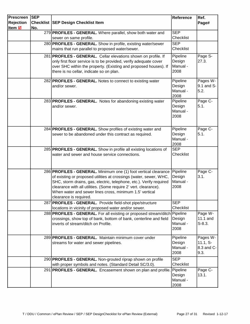
279 PROFILES - GENERAL. Where parallel, show both water and sewer on same profile.
SEP Checklist
280 PROFILES - GENERAL. Show in profile, existing water/sewer mains that run parallel to proposed water/sewer.
SEP Checklist
281 PROFILES - GENERAL. Cellar elevations shown on profile. If only first floor service is to be provided, verify adequate cover over SHC within the property. (Existing and proposed houses). If there is no cellar, indicate so on plan.
Pipeline Design Manual - 2008
Page S-27.3.
282 PROFILES - GENERAL. Notes to connect to existing water and/or sewer.
Pipeline Design Manual - 2008
Pages W-9.1 and S-5.2.
283 PROFILES - GENERAL. Notes for abandoning existing water and/or sewer.
Pipeline Design Manual - 2008
Page C-5.1.
284 PROFILES - GENERAL. Show profiles of existing water and sewer to be abandoned under this contract as required.
Pipeline Design Manual - 2008
Page C-5.1.
285 PROFILES - GENERAL. Show in profile all existing locations of water and sewer and house service connections.
SEP Checklist
286 PROFILES - GENERAL. Minimum one (1) foot vertical clearance of existing or proposed utilities at crossings (water, sewer, WHC, SHC, storm drains, gas, electric, telephone, etc.). Verify required clearance with all utilities. (Some require 2’ vert. clearance). When water and sewer lines cross, minimum 1.5’ vertical clearance is required.
Pipeline Design Manual - 2008
Page C-3.1.
287 PROFILES - GENERAL. Provide field-shot pipe/structure locations in vicinity of proposed water and/or sewer.
SEP Checklist
288 PROFILES - GENERAL. For all existing or proposed stream/ditch crossings, show top of bank, bottom of bank, centerline and field inverts of stream/ditch on Profile.
Pipeline Design Manual - 2008
Page W-11.1 and S-8.3.
289 PROFILES - GENERAL. Maintain minimum cover under streams for water and sewer pipelines.
Pipeline Design Manual - 2008
Pages W-11.1, S-8.3 and C-9.3.
290 PROFILES - GENERAL. Non-grouted riprap shown on profile with proper symbols and notes. (Standard Detail SC/3.0).
SEP Checklist
291 PROFILES - GENERAL. Encasement shown on plan and profile. Pipeline Design Manual - 2008
Page C-13.1.

T / DDU / Common / ePlan Review / SEP / SEP DesignChecklist for ePlan Review (External) Page 28 of 31 Revised 1-12-17
Prescreen Rejection Item
SEP Checklist No.
SEP Design Checklist ItemReference Ref.
Page#
292 PROFILES - GENERAL. Buoyancies of pipelines. Pipeline Design Manual - 2008
Page C-4.1.
293 PROFILES - GENERAL. Erosion check (ground over pipe 20% or greater). Every fifteen (15) feet, show number required on profile (Standard Detail M/3.0)
Pipeline Design Manual - 2008
Page C-7.1.
294 PROFILES - GENERAL. Concrete anchors for pipes. Pipeline Design Manual - 2008
Page C-14.1.
295 PROFILES - GENERAL. Larger than 24-inch, special design, calculations and special detail required.
Pipeline Design Manual - 2008
Page C-14.1.
296 PROFILES - GENERAL. 24-inch and smaller, anchors per Standard Detail M/4.0 shown on the drawings, ductile iron or AWWA C900 PVC noted on plan and profile.
Pipeline Design Manual - 2008
Page C-14.1.
297 PROFILES - WATER. Water sizes indicated on profile with bold text style.
SEP Checklist
298 PROFILES - WATER. Minimum cover over the top of the pipe is four (4) feet from the lowest profile grade or ground line. Future conditions should be considered at this time.
Pipeline Design Manual - 2008
Pages W-11.1 and W-11.2.
299 PROFILES - WATER. Water mains and structures shown at proper depth and verified with WSSC Standard Details
Pipeline Design Manual - 2008
Page W-11.2.
300 PROFILES - WATER. Stations in correct sequence. SEP Checklist
301 PROFILES - WATER. Compare water profile length with corresponding plan view.
Pipeline Design Manual - 2008
Page W-8.2.
302 PROFILES - WATER. Fittings at intersections same elevation. SEP Checklist
303 PROFILES - WATER. Fire hydrant lengths correct-submit tabulations.
Pipeline Design Manual - 2008
Pages W-24.1 & W-24.2.
304 PROFILES - WATER. Indicate restrained pipe on profile. Pipeline Design Manual - 2008
Page C-27.13.

T / DDU / Common / ePlan Review / SEP / SEP DesignChecklist for ePlan Review (External) Page 29 of 31 Revised 1-12-17
Prescreen Rejection Item
SEP Checklist No.
SEP Design Checklist ItemReference Ref.
Page#
305 PROFILES - WATER. Fittings labeled on profiles. Pipeline Design Manual - 2008
Page W-11.1.
306 PROFILES - WATER. Valves shall be placed on main where slope will allow valve to be operable.
Pipeline Design Manual - 2008
Page W-18.3.
307 PROFILES - WATER. Where water main is below or parallel to sewer, SHC or septic field, provide proper protection of water supply.
Pipeline Design Manual - 2008
Pages C-3.1 thru C-3.7 and C-13.1 thru C-13.2.
308 PROFILES - SEWER. Sewer sizes indicated on profile with bold text style.
SEP Checklist
309 PROFILES - SEWER. Sewers designed at normal depth, eight (8) to ten (10) feet, unless otherwise required by design.
Pipeline Design Manual - 2008
Page S-8.1.
310 PROFILES - SEWER. Compare sewer profile length with corresponding plan view.
SEP Checklist
311 PROFILES - SEWER. Existing, proposed or future grade lines shown, where required.
Pipeline Design Manual - 2008
Page S-8.4.
312 PROFILES - SEWER. Sewer pipelines at stream crossings - DIP for smaller than 21-inch sewer pipelines and DIP or RCP for 21-inch and larger sewer pipelines with twelve (12) foot lengths.
Pipeline Design Manual - 2008
Page S-8.2.
313 PROFILES - SEWER. Sewer pipelines at stream crossings - For RCP, label in profile and include in the general notes the pipe class required and minimum lay length of twelve (12) feet.
Pipeline Design Manual - 2008
Page S-8.2.
314 PROFILES - SEWER - SEWER GRADES / SLOPES. Note: slopes to be calculated by subtracting the manhole inside diameters from the center to center distance.
Pipeline Design Manual - 2008
Page S-15.1.
315 PROFILES - SEWER - SEWER GRADES / SLOPES. Sewer grades correct, submit tabulations if required.
SEP Checklist
316 PROFILES - SEWER - SEWER GRADES / SLOPES. Verify minimum slope requirements on Table 11, Page S-9.1 .0.60% minimum grade for 8-inch
Pipeline Design Manual - 2008
Page S-9.1.

T / DDU / Common / ePlan Review / SEP / SEP DesignChecklist for ePlan Review (External) Page 30 of 31 Revised 1-12-17
Prescreen Rejection Item
SEP Checklist No.
SEP Design Checklist ItemReference Ref.
Page#
317 PROFILES - SEWER - SEWER GRADES / SLOPES. Minimum grade 1.00% for terminal sewers
Pipeline Design Manual - 2008
Page S-9.1.
318 PROFILES - SEWER - SEWER GRADES / SLOPES. Sewer pipeline on steep grades, ten (10%) percent and greater. Ductile Iron Pipe or PVC AWWA C-900 for 12-INCH and smaller and Ductile Iron Pipe or PVC AWWA C-905 for larger than 12-INCH.
Pipeline Design Manual - 2008
Page S-15.3.
319 PROFILES - SEWER - MANHOLES. Manhole depths within Standard Details limitations. Sewers designed at normal depth (up to ten (10) feet) unless specified in report or required by conditions/design.
Pipeline Design Manual - 2008
Page S-18.1.
320 PROFILES - SEWER - MANHOLES. Frame and cover set at proposed elevation shown on profile, one (1) foot above existing ground or at existing grade.
Pipeline Design Manual - 2008
Page S-11.2.
321 PROFILES - SEWER - MANHOLES. Shallow manhole specified on profile.
Pipeline Design Manual - 2008
Page S-18.1.
322 PROFILES - SEWER - MANHOLES. Type of existing manhole. (Indicate brick or precast)
Pipeline Design Manual - 2008
Page S-12.1.
323 PROFILES - SEWER - MANHOLES. Manhole drop connections labeled on profile.
Pipeline Design Manual - 2008
Page S-16.1.
324 PROFILES - SEWER - MANHOLES. Invert elevations at intersection coincide.
SEP Checklist
325 PROFILES - SEWER - MANHOLES. Rim elevations shown, submit tabulations. Verify rim elevations with other profiles.
SEP Checklist
326 PROFILES - SEWER - MANHOLES. Invert elevations correct, proper jump in inverts between different sizes. Provide 0.10’ minimum drop through manhole.
Pipeline Design Manual - 2008
Page S-17.1 thru S-17.6.
327 PROFILES - SEWER - MANHOLES. DHC’s shown, station and top elevation.
Pipeline Design Manual - 2008
Page S-27.4.
328 PROFILES - SEWER - MANHOLES. Special design for manholes over twenty four (24) feet deep.
Pipeline Design Manual - 2008
Page S-18.1.
329 PROFILES - SEWER - MANHOLES. Fall prevention systems for manholes over twenty (20) feet deep (minimum 60” diameter manhole) shown in profile and specified in General Notes.
Pipeline Design Manual - 2008
Pages S-18.1 and S-20.1.

T / DDU / Common / ePlan Review / SEP / SEP DesignChecklist for ePlan Review (External) Page 31 of 31 Revised 1-12-17
Prescreen Rejection Item
SEP Checklist No.
SEP Design Checklist ItemReference Ref.
Page#
330 PROFILES - SEWER - MANHOLES. Show correct cross-slope on rim when within roadway or paving.
Pipeline Design Manual - 2008
Page S-11.2. Show correct cross-slope on rim. Page S-17.3.
331 PROFILES - SEWER - PRESSURE SEWER / FORCE MAINS. Air/vacuum and air release valves provided at high points. Ideally, high points should be avoided.
Pipeline Design Manual - 2008
Pages S-25.3 and S-25.4.
332 PROFILES - SEWER - PRESSURE SEWER / FORCE MAINS. Flushing connections every four hundred (400) ± feet and at dead ends.
Pipeline Design Manual - 2008
Page S-25.4.
333 PROFILES - SEWER - PRESSURE SEWER / FORCE MAINS. Transition manhole at pressure sewer connection to gravity system. SD PS/4.0, PS/4.1& PS/4.2
Pipeline Design Manual - 2008
Page S-25.4.
334 OTHER DOCUMENTS - PRIVATE EASEMENT AGREEMENT. Used for properties owned by different owners.
SEP Checklist
335 OTHER DOCUMENTS - DECLARATION OF COVENANTS (regarding easements). Used for properties owned by the same owner.
SEP Checklist
336 OTHER DOCUMENTS - COVENANT AGREEMENT. Used for multiple buildings, owned by same owner, sharing one service connection.
SEP Checklist
337 OTHER DOCUMENTS - ADDRESS ASSIGNMENT/ VERIFICATION DOCUMENT. Provide a copy of the Address Assignment/Verification Document approved by MNCPPC. Acceptable documentation includes 1) a direct email to WSSC from either county MNCPPC address verification department; 2) Address Assignment Site plan or letter (on letterhead) with approval stamp and/or signature by MNCPPC.
SEP Checklist