separated combustion - reznorhvac.com (12-14) pn195676r17 smallest.pdf · separated-combustion unit...
TRANSCRIPT
Form I-UD-V-SC, PN195676R17, Page 1
APPLIES TO: Venting Requirements for Model UDAS and Model UDBS and
Instructions for Combustion Air Inlet / Vent Terminal Options CC6 and CC2
Form I-UD-V-SC (12-14) Obsoletes Form I-UD-V-SC (Version E.2) �
General
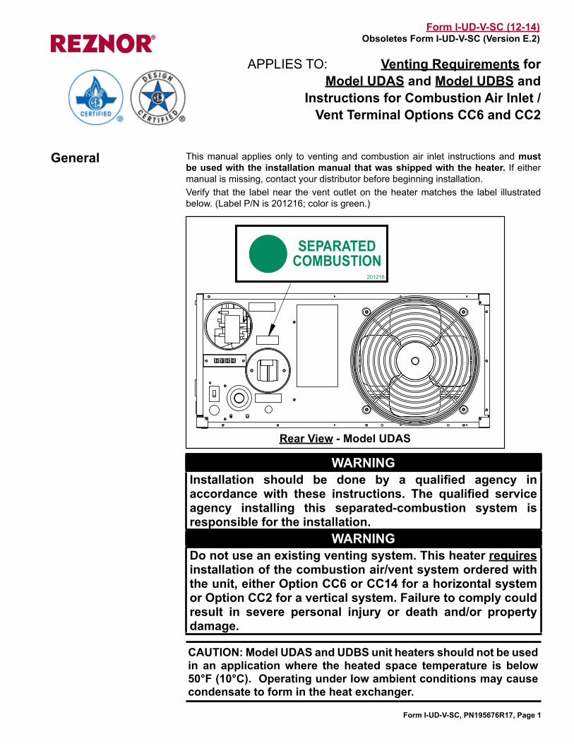
SEPARATEDCOMBUSTION
201216
This manual applies only to venting and combustion air inlet instructions and must be used with the installation manual that was shipped with the heater. If either manual is missing, contact your distributor before beginning installation. Verify that the label near the vent outlet on the heater matches the label illustrated below. (Label P/N is 201216; color is green.)
WARNINGInstallation should be done by a qualified agency in accordance with these instructions. The qualified service agency installing this separated-combustion system is responsible for the installation.
WARNING Do not use an existing venting system. This heater requires installation of the combustion air/vent system ordered with the unit, either Option CC6 or CC14 for a horizontal system or Option CC2 for a vertical system. Failure to comply could result in severe personal injury or death and/or property damage.
Rear View - Model UDAS
CAUTION: Model UDAS and UDBS unit heaters should not be used in an application where the heated space temperature is below 50°F (10°C). Operating under low ambient conditions may cause condensate to form in the heat exchanger.
Form I-UD-V-SC, PN195676R17, Page 2
Is the Installation Residential or Commercial/Industrial?
Hazards of Chlorine
1.0 Venting and Combustion Air Requirements for Separated Combustion Models UDAS and UDBS
All separated combustion units MUST BE equipped with both combustion air and exhaust piping to the outdoors. The unique concentric adapter assembly required with this heater allows for both combustion air and exhaust piping with only one horizontal or vertical penetration hole in the building.When an existing appliance is removed or replaced in a venting system, the venting system may not be properly sized to vent the attached appliances. An improperly sized venting system may result in the formation of condensate, leakage, and/or spillage.Concentric horizontal and vertical vent/combustion air systems are the only venting/combustion air systems approved for Model UDAS and Model UDBS separated-combustion unit heaters. Model UDAS 30, 45, 60, 75, 100, and 125 are certified for both residential and com-mercial/industrial installations. Utility heaters certified for “residential use” are intended for heating of non-living spaces that are attached to, or part of, a structure that contains space for family living quarters. They are not intended to be the primary source of heat in residential applications or to be used in sleeping quarters.Model UDAS 150, 175, 200, 225, 250, 300, 350, and 400 and Model UDBS 30, 45, 60, 75, 100, 125, 150, 175, 200, 225, 250, 300, 350, and 400 are certified only for com-mercial/industrial installations.The presence of chlorine vapors in the combustion air of gas-fired heating equipment presents a potential corrosion hazard. Chlorine found usually in the form of freon or degreaser vapors, when exposed to flame will precipitate from the compound, and go into solution with any condensation that is present in the heat exchanger or associated parts. The result is hydrochloric acid which readily attacks all metals including 300 grade stainless steel. Care should be taken to separate these vapors from the com-bustion process. This may be done by wise location of the combustion air terminal with regard to exhausters or prevailing wind directions. Chlorine is heavier than air. Keep these facts in mind when determining installation location of the heater in relation to building exhaust systems.
General ............................................................ 11.0 Venting and Combustion Air
Requirements for Separated Combustion Models UDAS & UDBS .... 2-81.1 Type of Pipe ................................................ 31.2 Venter Outlet and Combustion Air Inlet ....... 31.3 Pipe Diameter and Length ........................... 41.4 Joints and Sealing ...................................... 41.5 Support ........................................................ 51.6 Clearance .................................................... 51.7 Condensation .............................................. 61.8 Concentric Adapter Box ............................... 6
2.0 HORIZONTAL VENT INSTRUCTIONS - Option CC6 ........................................... 9-122.1 Components Required - Factory & Field ..... 92.2 Installation Instructions for Horizontal
Vent/Combustion Air Kit Option CC6 ........103.0 VERTICAL VENT INSTRUCTIONS -
Option CC2 ........................................ 12-153.1 Components Required - Factory & Field ... 123.2 Installation Instructions for Vertical
Vent/Combustion Air Kit Option CC2 ..... 13
INDEX............................................................. 16
Table of Contents
The requirements in Venting Requirement 1.1, Type of Vent Pipe, are not the same for Residential and Commercial/Industrial installations. Other venting requirements (1.2 through 1.8) are the same for both. The installation instructions in Paragraphs 2 and 3 apply to both residential and com-mercial/industrial installations. The testing requirement in Paragraph 4 applies to a residential installation. Read the headings and comply with the requirements that apply to the type of instal-lation.
Form I-UD-V-SC, PN195676R17, Page 3
1.1 Type of Pipe All pipe is field supplied. Select installation type that applies. Requirements are listed for both the vent pipe and the combustion air inlet pipe.
1.1.1 Residential Installation - Pipe RequirementsNOTE: Only UDAS 30, 45, 60, 75, 100, and 125 are certified for residential use.
1.1.2 Commercial/Industrial Installation - Pipe Requirements
Horizontal or Vertical Vent Pipe Run
Vent pipe approved to UL Std 1738 for a Category III appliance is required.The horizontal section of pipe in the vent terminal that extends through the box and runs concentric through the combustion air pipe must be one-piece with no joints.
Horizontal Vent Terminal (using Option CC6 Kit)Vertical Vent Terminal (using Option CC2 Kit)
Double-wall vent pipe approved to UL Std 1738 for a Category III appliance is required The section of pipe in the vent terminal that extends through the box and runs concentric through the combustion air pipe must be one-piece with no joints.
Combustion Air Inlet Pipe (Options CC2 & CC6)
Sealed, single-wall galvanized pipe is recommended for inlet air run and terminal combustion air pipe.
1.2 Venter Outlet and Combustion Air Inlet
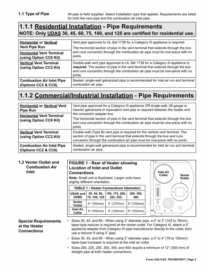
FIGURE 1 - Rear of Heater showing Location of Inlet and Outlet ConnectionsNote: Small unit is illustrated. Larger units have slightly different orientation.
��������������� ������
������
TABLE 1 - Heater Connections (diameter) UDAS and
UDBS30, 45, 60,
75, 100, 125150, 175, 200,
225, 250, 300, 350,
400Venter Outlet 4” (102mm) 5” (127mm) 6” (152mm)
Inlet Air Collar 4” (102mm) 6” (152mm) 6” (152mm)
Special Requirements at the Heater Connections
• Sizes 30, 45, and 60 - When using 3” diameter pipe, a 4” to 3” (102 to 76mm) taper-type reducer is required at the venter outlet. For Category III, attach a 4” appliance adapter from Category III pipe manufacturer directly to the collar, then use a reducer if using 3” pipe.
• Sizes 30, 45, and 60 - When using 3” diameter pipe, a 3” to 4” (76 to 102mm) taper-type increaser is required at the inlet air collar.
• Sizes 200, 225, 250, 300, 350, and 400 require a minimum of 12” (305 mm) of straight pipe at both heater connections.
Horizontal or Vertical Vent Pipe Run
Vent pipe approved for a Category III appliance OR single-wall, 26-gauge or heavier galvanized or equivalent vent pipe is required between the heater and the concentric adapter box.The horizontal section of pipe in the vent terminal that extends through the box and runs concentric through the combustion air pipe must be one-piece with no joints.
Horizontal Vent Terminal (using Option CC6 Kit)
Vertical Vent Terminal (using Option CC2 Kit)
Double-wall (Type B) vent pipe is required for the vertical vent terminal. The section of pipe in the vent terminal that extends through the box and runs concentric through the combustion air pipe must be one-piece with no joints.
Combustion Air Inlet Pipe (Options CC2 & CC6)
Sealed, single-wall galvanized pipe is recommended for inlet air run and terminal combustion air pipe.

Form I-UD-V-SC, PN195676R17, Page 4
Applies to: Residential or Commercial/Industrial Installation NOTE: Only UDAS 30, 45, 60, 75, 100, and 125 are certified for residential use.
Diameters of the outside (terminal) concentric pipes are listed in TABLE 3.
1.3 Pipe Diameter and Length
Pipe diameter and length requirements listed in TABLE 2 are for the indoor sections of pipe between the heater and the concentric adapter box. Pipe diameters and maximum indoor vent lengths in TABLE 2 apply to both horizon-tal and vertical vent/combustion air systems. Add all straight sections and equivalent lengths for elbows. The total length of the straight sections and elbows must not exceed the Maximum Length.
TABLE 2 - Pipe Diameter and Length from Heater to Concentric Adapter Box
• Minimum length between the heater and the concentric adapter box is 1 ft (305mm) for Sizes 30-125 and 3 ft (914mm) for Sizes 150-400.
1.4 Joints and Sealing Provide pipes as specified in Requirement No. 1.1, page 3, and seal joints as follows:• To join sections of Category III pipe, follow the pipe manufacturer’s instructions
for joining and sealing.• To join sections of single-wall pipe (vent pipe or combustion air pipe), secure
slip-fit pipe connections using sheetmetal screws or rivets. Seal all joints with aluminum tape or silicone sealant.
• When joining the terminal section of double-wall vent pipe (vertical vent terminal Option CC2 only) to the vent cap, follow the illustrated step-by-step instructions in FIGURE 2.When joining a terminal section of double-wall vent pipe to a single-wall a vent pipe run, follow the illustrated step-by-step instructions in FIGURE 3.When joining two sections of double-wall vent pipe, follow the pipe manufacturer’s instructions for joining and sealing vent pipe sections.
NOTE: Joints connecting double-wall pipe apply only to a vertical vent terminal (Option CC2 Vertical Vent/Combustion Air Kit). See Type of Pipe requirement on page 3.
UDAS and UDBS 30, 45, 60, 75, 100, 125 150, 175, 200, 225, 250, 300, 350, 400Inlet Air Pipe Diameter 6” (152mm) 8” (203mm)Vent Pipe Diameter 4” (102mm) 5” (127mm)
Pipe Diameter and Maximum Length from Heater to Concentric Adapter Box UDAS and
UDBS
Pipe Diameter Maximum Length
Equivalent Straight Length for aVent Pipe Inlet Air Pipe 90° Elbow 45° Elbow
inches mm inches mm feet M feet M feet M
30 3 76 3 76 15 4.6 2 0.6 1 0.34 102 4 102 10 3.0 2 0.6 1 0.3
45 3 76 3 76 15 4.6 2 0.6 1 0.34 102 4 102 10 3.0 2 0.6 1 0.3
60 3 76 3 76 25 7.6 3 0.9 1.5 0.54 102 4 102 15 4.6 1.5 0.5 1 0.3
75 4 102 4 102 25 7.6 3 0.9 1.5 0.5100 4 102 4 102 35 10.7 4 1.2 2 0.6125 4 102 4 102 35 10.7 4 1.2 2 0.6150 5 127 6 152 30 9.1 3 0.9 1.5 0.5175 5 127 6 152 30 9.1 3 0.9 2 0.5200 5 127 6 152 40 12.2 4 1.2 2 0.6225 5 127 6 152 40 12.2 4 1.2 2 0.6250 5 127 6 152 40 12.2 4 1.2 2 0.6300 6 152 6 152 45 13.7 4 1.2 2 0.6350 6 152 6 152 45 13.7 5 1.5 2.5 0.8400 6 152 6 152 45 13.7 5 1.5 2.5 0.8
The outdoor pipe lengths depend on the installation; requirements are listed in the installation instructions for the hori-zontal (Option CC6) and vertical (Option CC2) vent/combustion air kits.
TABLE 3 - Diameters of Concentric (outdoor) Pipes
1.0 Venting and Combustion Air Requirements (cont’d)
Form I-UD-V-SC, PN195676R17, Page 5
Applies to: Residential or Commercial/Industrial InstallationNOTE: Only UDAS 30, 45, 60, 75, 100, and 125 are certified for residential use.
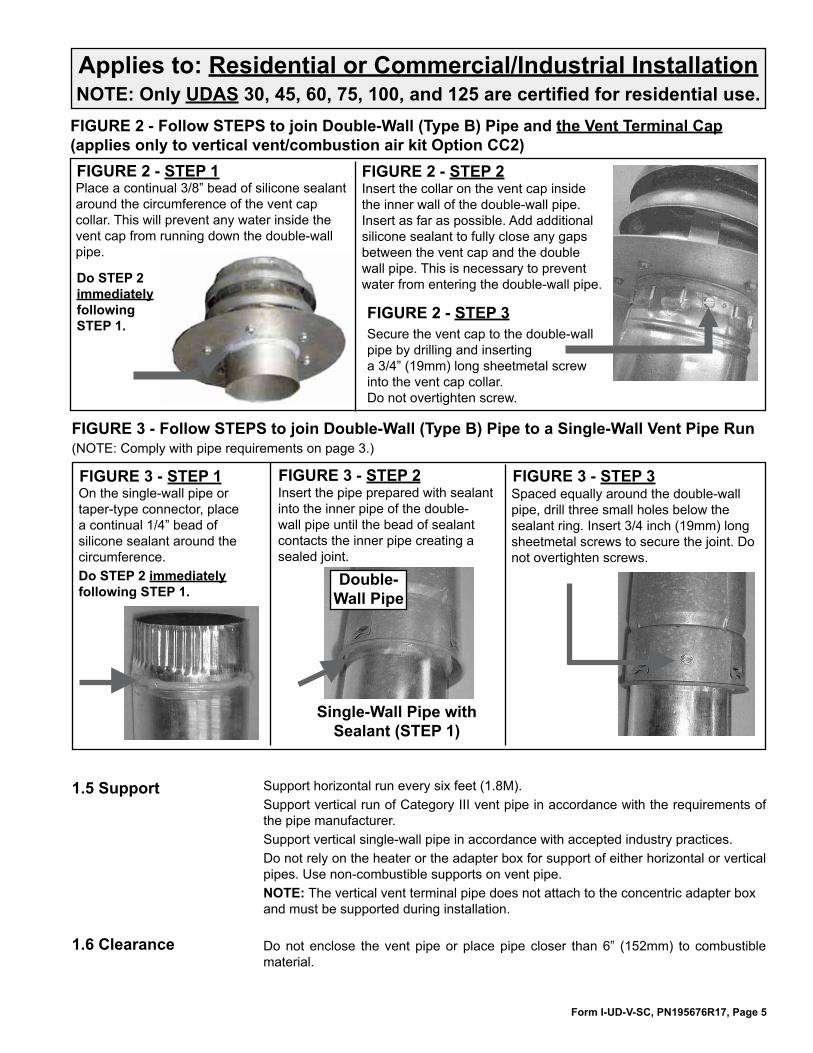
FIGURE 2 - Follow STEPS to join Double-Wall (Type B) Pipe and the Vent Terminal Cap (applies only to vertical vent/combustion air kit Option CC2)FIGURE 2 - STEP 1Place a continual 3/8” bead of silicone sealant around the circumference of the vent cap collar. This will prevent any water inside the vent cap from running down the double-wall pipe.
FIGURE 2 - STEP 2Insert the collar on the vent cap inside the inner wall of the double-wall pipe. Insert as far as possible. Add additional silicone sealant to fully close any gaps between the vent cap and the double wall pipe. This is necessary to prevent water from entering the double-wall pipe.
Secure the vent cap to the double-wall pipe by drilling and inserting a 3/4” (19mm) long sheetmetal screw into the vent cap collar. Do not overtighten screw.
FIGURE 2 - STEP 3
FIGURE 3 - Follow STEPS to join Double-Wall (Type B) Pipe to a Single-Wall Vent Pipe Run(NOTE: Comply with pipe requirements on page 3.)
Do STEP 2 immediately following STEP 1.
FIGURE 3 - STEP 1On the single-wall pipe or taper-type connector, place a continual 1/4” bead of silicone sealant around the circumference. Do STEP 2 immediately following STEP 1.
FIGURE 3 - STEP 2Insert the pipe prepared with sealant into the inner pipe of the double-wall pipe until the bead of sealant contacts the inner pipe creating a sealed joint.
FIGURE 3 - STEP 3Spaced equally around the double-wall pipe, drill three small holes below the sealant ring. Insert 3/4 inch (19mm) long sheetmetal screws to secure the joint. Do not overtighten screws.
Double- Wall Pipe
Single-Wall Pipe with Sealant (STEP 1)
1.5 Support Support horizontal run every six feet (1.8M). Support vertical run of Category III vent pipe in accordance with the requirements of the pipe manufacturer. Support vertical single-wall pipe in accordance with accepted industry practices. Do not rely on the heater or the adapter box for support of either horizontal or vertical pipes. Use non-combustible supports on vent pipe.NOTE: The vertical vent terminal pipe does not attach to the concentric adapter box and must be supported during installation.
1.6 Clearance Do not enclose the vent pipe or place pipe closer than 6” (152mm) to combustible material.
Form I-UD-V-SC, PN195676R17, Page 6
Applies to: Residential or Commercial/Industrial Installation NOTE: Only UDAS 30, 45, 60, 75, 100, and 125 are certified for residential use.
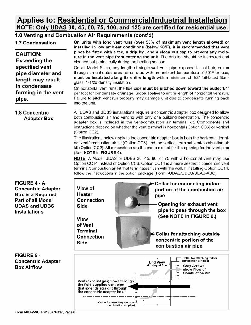
1.0 Venting and Combustion Air Requirements (cont’d)1.7 Condensation On units with long vent runs (over 50% of maximum vent length allowed) or
installed in low ambient conditions (below 50°F), it is recommended that vent pipes be fitted with a tee, a drip leg, and a clean out cap to prevent any mois-ture in the vent pipe from entering the unit. The drip leg should be inspected and cleaned out periodically during the heating season.On all Model Sizes, any length of single-wall vent pipe exposed to cold air, or run through an unheated area, or an area with an ambient temperature of 50°F or less, must be insulated along its entire length with a minimum of 1/2” foil-faced fiber-glass, 1-1/2# density insulation.On horizontal vent runs, the flue pipe must be pitched down toward the outlet 1/4” per foot for condensate drainage. Slope applies to entire length of horizontal vent run. Failure to pitch vent run properly may damage unit due to condensate running back into the unit.
1.8 Concentric Adapter Box
FIGURE 4 - A Concentric Adapter Box is a Required Part of all Model UDAS and UDBS Installations
View of Heater Connection Side
Collar for attaching outside concentric portion of the combustion air pipe
Collar for connecting indoor portion of the combustion air pipe
Opening for exhaust vent pipe to pass through the box (See NOTE in FIGURE 6.)View
of Vent Terminal Connection Side
CAUTION: Exceeding the specified vent pipe diameter and length may result in condensate forming in the vent pipe.
����������������������� ����� �����
��������������������� ��
�������������������������������������������������������������������������������������������������������������������
����������������������������������������������
�����������������������������������������������
FIGURE 5 - Concentric Adapter Box Airflow
All UDAS and UDBS installations require a concentric adapter box designed to allow both combustion air and venting with only one building penetration. The concentric adapter box is included in the vent/combustion air terminal kit. Components and instructions depend on whether the vent terminal is horizontal (Option CC6) or vertical (Option CC2).The illustrations below apply to the concentric adapter box in both the horizontal termi-nal vent/combustion air kit (Option CC6) and the vertical terminal vent/combustion air kit (Option CC2). All dimensions are the same except for the opening for the vent pipe (See NOTE in FIGURE 6).NOTE: A Model UDAS or UDBS 30, 45, 60, or 75 with a horizontal vent may use Option CC14 instead of Option CC6. Option CC14 is a more aesthetic concentric vent terminal/combustion air kit that terminates flush with the wall. If installing Option CC14, follow the instructions in the option package (Form I-UDAS/UDBS/UEAS-ASC).
Form I-UD-V-SC, PN195676R17, Page 7
Applies to: Residential or Commercial/Industrial Installation NOTE: Only UDAS 30, 45, 60, 75, 100, and 125 are certified for residential use.
���������������������������������� ��� ���������������
���������������������������������� ��� ����������������
�������� ��������
���������������� ����������������
���������� ���������������
������ ���������������
�����������������������
������������������� ���������������������������
����������������������������������������� ���������������������
���������
���������
�������������
��������������������� ���������
�������������������� ����������
����������
�����������
������������
���������������
���������
������������
�������������
���������
�������������
�������������
���������
��������������
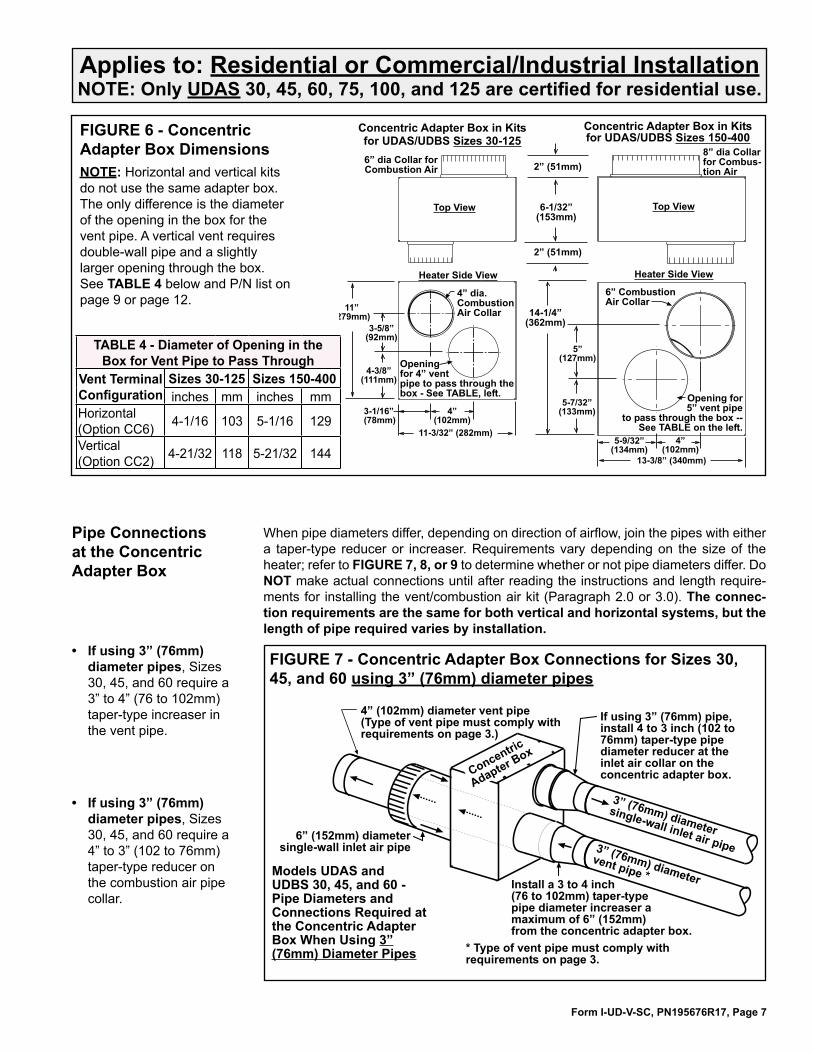
FIGURE 6 - Concentric Adapter Box DimensionsNOTE: Horizontal and vertical kits do not use the same adapter box. The only difference is the diameter of the opening in the box for the vent pipe. A vertical vent requires double-wall pipe and a slightly larger opening through the box. See TABLE 4 below and P/N list on page 9 or page 12.
TABLE 4 - Diameter of Opening in the Box for Vent Pipe to Pass Through
Vent Terminal Configuration
Sizes 30-125 Sizes 150-400inches mm inches mm
Horizontal (Option CC6) 4-1/16 103 5-1/16 129
Vertical (Option CC2) 4-21/32 118 5-21/32 144
Pipe Connections at the Concentric Adapter Box
When pipe diameters differ, depending on direction of airflow, join the pipes with either a taper-type reducer or increaser. Requirements vary depending on the size of the heater; refer to FIGURE 7, 8, or 9 to determine whether or not pipe diameters differ. Do NOT make actual connections until after reading the instructions and length require-ments for installing the vent/combustion air kit (Paragraph 2.0 or 3.0). The connec-tion requirements are the same for both vertical and horizontal systems, but the length of pipe required varies by installation.
• If using 3” (76mm) diameter pipes, Sizes 30, 45, and 60 require a 3” to 4” (76 to 102mm) taper-type increaser in the vent pipe.
�������
���
�������
����
���������� �������������������������������������������������������������������������������������������������������������
������� � ������������������������ �����������������������������������������������������������������������������������������������������
�������������������� ����������������������������������������������������������������������������������������� � ��������������������
�������������������������������������������������������������������������������� �� ��
��������������������� ����������������������
���������������
��� ���������������������� ���������������
�����������
������������������������������������������������������ �� �
• If using 3” (76mm) diameter pipes, Sizes 30, 45, and 60 require a 4” to 3” (102 to 76mm) taper-type reducer on the combustion air pipe collar.
FIGURE 7 - Concentric Adapter Box Connections for Sizes 30, 45, and 60 using 3” (76mm) diameter pipes
Form I-UD-V-SC, PN195676R17, Page 8
Applies to: Residential or Commercial/Industrial Installation NOTE: Only UDAS 30, 45, 60, 75, 100, and 125 are certified for residential use.
1.0 Venting and Combustion Air Requirements (cont’d)1.8 Concentric Adapter Box (cont’d)
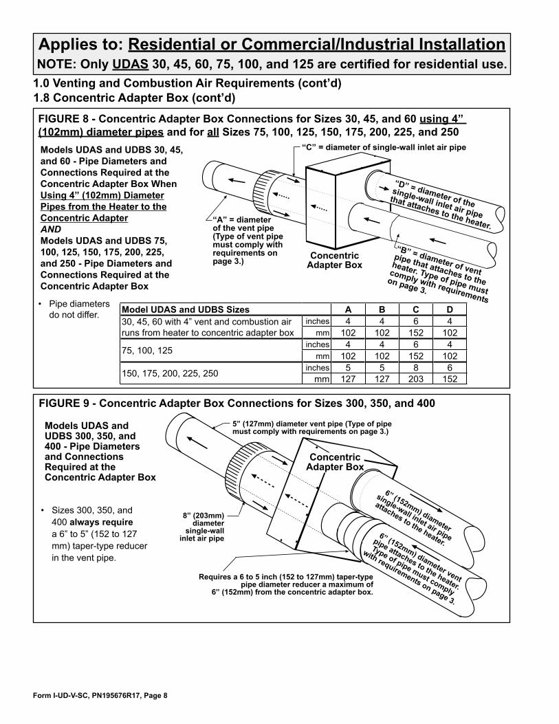
FIGURE 8 - Concentric Adapter Box Connections for Sizes 30, 45, and 60 using 4” (102mm) diameter pipes and for all Sizes 75, 100, 125, 150, 175, 200, 225, and 250 �������������������������� ������������������������������������������������������������������������������������ ��������������������������������������������������������������������������������� ������ �� ���� ��������� ������ �����������������������������������������������������������������
��������������������
���������������������
������������������������
������������������������
����������������������
����������
��������������������
����������������������
����������������������������
���������������������������������������
���������������������������� �����������������������������������������������������
• Pipe diameters do not differ. Model UDAS and UDBS Sizes A B C D
30, 45, 60 with 4” vent and combustion air runs from heater to concentric adapter box
inches 4 4 6 4mm 102 102 152 102
75, 100, 125inches 4 4 6 4
mm 102 102 152 102
150, 175, 200, 225, 250 inches 5 5 8 6mm 127 127 203 152
FIGURE 9 - Concentric Adapter Box Connections for Sizes 300, 350, and 400
��������������������������������� ����������������������������������������������������������������
������������������������������� ����������������������������������������
����������������������������������������
������ ���������������������������������������������������������������
����������������
�������������������
�����������������
��������������������
���������������������������������������������
�������������������������
�������������������
�������������������������
�������������������
• Sizes 300, 350, and 400 always require a 6” to 5” (152 to 127 mm) taper-type reducer in the vent pipe.
Form I-UD-V-SC, PN195676R17, Page 9
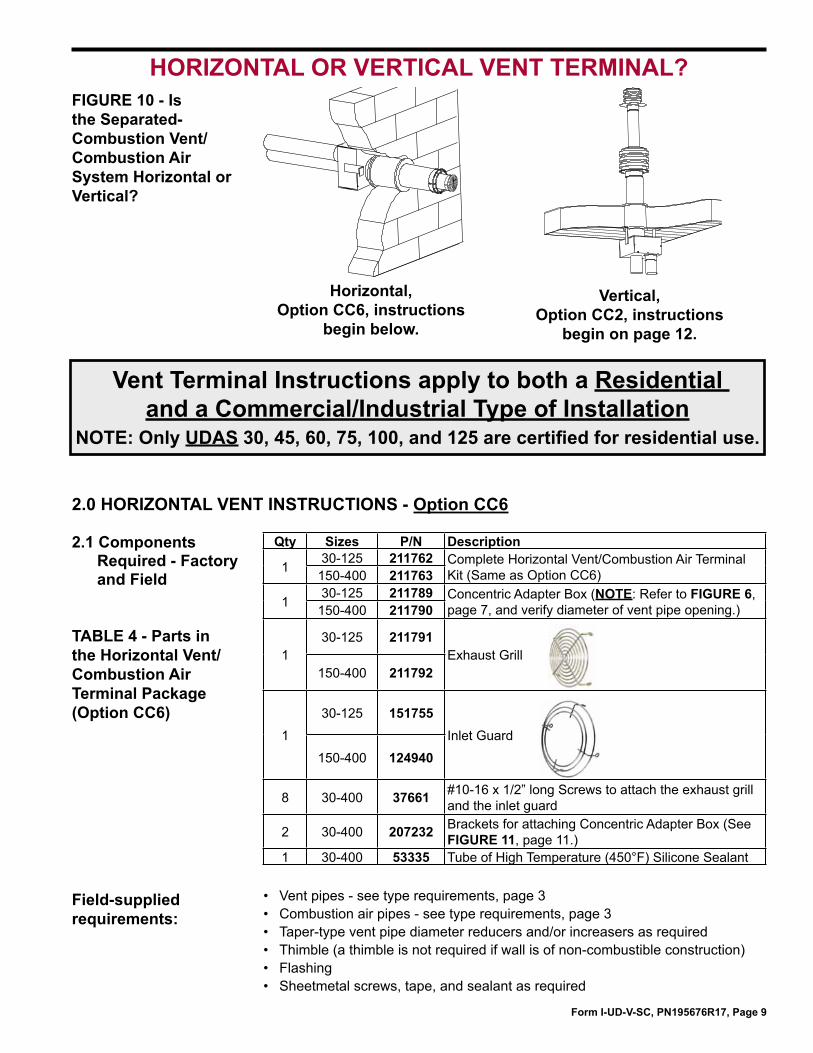
Horizontal, Option CC6, instructions
begin below.
Vertical, Option CC2, instructions
begin on page 12.
FIGURE 10 - Is the Separated-Combustion Vent/Combustion Air System Horizontal or Vertical?
HORIZONTAL OR VERTICAL VENT TERMINAL?
Vent Terminal Instructions apply to both a Residential and a Commercial/Industrial Type of Installation
NOTE: Only UDAS 30, 45, 60, 75, 100, and 125 are certified for residential use.
2.0 HORIZONTAL VENT INSTRUCTIONS - Option CC6
2.1 Components Required - Factory and Field
TABLE 4 - Parts in the Horizontal Vent/Combustion Air Terminal Package (Option CC6)
Field-supplied requirements:
• Vent pipes - see type requirements, page 3• Combustion air pipes - see type requirements, page 3• Taper-type vent pipe diameter reducers and/or increasers as required• Thimble (a thimble is not required if wall is of non-combustible construction) • Flashing• Sheetmetal screws, tape, and sealant as required
Qty Sizes P/N Description
130-125 211762 Complete Horizontal Vent/Combustion Air Terminal
Kit (Same as Option CC6)150-400 211763
130-125 211789 Concentric Adapter Box (NOTE: Refer to FIGURE 6,
page 7, and verify diameter of vent pipe opening.)150-400 211790
130-125 211791
Exhaust Grill150-400 211792
1
30-125 151755Inlet Guard
150-400 124940
8 30-400 37661 #10-16 x 1/2” long Screws to attach the exhaust grill and the inlet guard
2 30-400 207232 Brackets for attaching Concentric Adapter Box (See FIGURE 11, page 11.)
1 30-400 53335 Tube of High Temperature (450°F) Silicone Sealant

Form I-UD-V-SC, PN195676R17, Page 10
1) Determine the location on the outside wall for the vent terminal. Location must comply with vent length requirements, Requirement No. 1.3 on page 4. In most applications, the terminal would be on a level with the heater mounting height. Allow 1/4” per foot (6mm per 305mm) downward pitch for condensate drain. Minimum clearances for the horizontal vent terminal are shown in TABLE 5. Also, select a location that complies with adjoining building clearances as shown in FIGURE 12, pages 11- 12.Products of combustion can cause discoloring of some building finishes and deterioration of masonry materials. Applying a clear silicone sealant that is normally used to protect concrete driveways can protect masonry materials. If discoloration is an esthetic problem, re-locate the vent or install a vertical vent.
Before beginning, verify that the kit is at the site and that all components are correct for the installation. Be sure all required field-supplied parts are available.
WARNINGAll vent terminals must be positioned or located away from fresh air intakes, doors and windows to preclude combustion products from entering occupied space. Failure to comply could result in severe personal injury or death and/or property damage.
TABLE 5 - Clearances to Horizontal Vent Terminal
Structure Minimum Clearances for Vent Terminal Location (all directions unless specified)
Forced air inlet within 10 ft (3.1M)* 3 ft (0.9M) aboveCombustion air inlet of another appliance 6 ft (1.8M)
Door, window, or gravity air inlet (any building opening)
4 ft (1.2M) horizontally4 ft (1.2M) below1 ft (305mm) above
Electric meter, gas meter ** and relief equipment
U.S. - 4 ft (1.2M) horizontallyCanada - 6 ft (1.8M)
Gas regulator ** 3 ft (0.9M) horizontally Adjoining building or parapet 6 ft (1.8M)Adjacent public walkways 7 ft (2.1M) aboveGrade (ground level) 3 ft (0.9M) above****Does not apply to the inlet of a direct vent appliance. **Do not terminate the vent directly above a gas meter or service regulator. *** Consider local snow depth conditions. The vent must be at least 6” (152mm) higher than anticipated snow depth.
2) Install the Vent Pipe and Combustion Air Pipe Runs - Use the type of pipe specified in Requirement No. 1.1, page 3. Comply with requirements in Requirement No. 1.2, page 3, when attaching pipes to the heater. Length must comply with Requirement 1.3, page 4.Seal all joints. Due to the high temperature, do not enclose the vent (exhaust) pipe or place pipe closer than 6” (152 mm) to combustible material. Extend the runs close to the wall location selected in Step 1). Support pipes as required in Requirement No. 1.5, page 5. Comply with requirements concerning condensation in Paragraph 1.7.
3) Prepare a clearance hole through the outside wall for the combustion air pipe -- a 6” (152mm) diameter pipe for Sizes 30-125 or an 8” (203mm) diameter pipe for Sizes 150-400. Outside wall construction thickness should be 1” (25mm) minimum and 48” (1219 maximum). The larger diameter combustion air pipe serves as clearance for the vent pipe on non-
combustible construction. A thimble may be required depending on wall construction and/or local codes.
4) Prepare the Concentric Adapter Box a. Attach the brackets to the box. Follow the instructions
in FIGURE 11. b. Attach the outside portion of the combustion air
pipe to the box. Determine the length by measuring the bracket length from box to wall, plus the wall thickness, plus 4-16” (102-406 mm) beyond the wall. (The inlet air pipe should extend beyond the outside wall a minimum of 4” (102mm) to a maximum or 16” (406mm).Attach the inlet air pipe to the collar of the concentric adapter with sheetmetal screws and seal.
5) Attach the concentric adapter box to the wall. Insert the combustion air pipe out through the wall. Attach the brackets (FIGURE 11) to the wall. On the outside, caulk or flash the inlet air pipe. Flashing is field-supplied.
2.2 Installation Instructions for Horizontal Vent/Combustion Air Kit Option CC6 (in compliance with requirements on pages 3-8)
2.0 HORIZONTAL VENT INSTRUCTIONS - Option CC6 (cont’d)
Form I-UD-V-SC, PN195676R17, Page 11
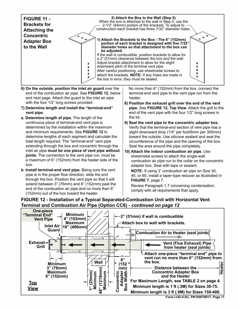
FIGURE 11 - Brackets for Attaching the Concentric Adapter Box to the Wall
����������������������������������������� ���������������������������������������������������������� ������������������������������������������������������������ ��������������������������������������� �������������������������������������� ��������� ���������� ���������������������������������� ���������������������������� ����������������������� ����� ���������������������������� � ���������������������������������������������������������� ������������������ ��������� ����������������������������
���������������������������������������� ���������������������������������� ����������������
��������������� �������������������������������� �������� ������������������������������������������
6) On the outside, position the inlet air guard over the end of the combustion air pipe. See FIGURE 12, below and next page. Attach the guard to the inlet air pipe with the four 1/2” long screws provided.
7) Determine length and install the “terminal-end” vent pipe.
a. Determine length of pipe. The length of the continuous piece of terminal-end vent pipe is determined by the installation within the maximum and minimum requirements. See FIGURE 12 to determine lengths of each segment and calculate the total length required. The “terminal-end” vent pipe extending through the box and concentric through the inlet air pipe must be one piece of vent pipe without joints. The connection to the vent pipe run, must be a maximum of 6” (152mm) from the heater side of the box.
b. Install terminal-end vent pipe. Being sure the vent pipe is in the proper flow direction, slide the end through the box. Position the vent pipe so that it will extend between 3” (76mm) and 6” (152mm) past the end of the combustion air pipe and no more than 6” (152mm) out of the box toward the heater.
No more than 6” (152mm) from the box, connect the terminal-end vent pipe to the vent pipe run from the heater.
8) Position the exhaust grill over the end of the vent pipe. See FIGURE 12, Top View. Attach the grill to the end of the vent pipe with the four 1/2” long screws in the kit.
9) Seal the vent pipe to the concentric adapter box. Verify that the terminal-end section of vent pipe has a slight downward drop (1/4” per foot/6mm per 305mm) toward the outside. Use silicone sealant and seal the circumference of the pipe and the opening of the box. Seal the area around the pipe completely.
10) Attach the indoor combustion air pipe. Use sheetmetal screws to attach the single-wall combustion air pipe run to the collar on the concentric adapter box. Seal with tape or sealant. NOTE: If using 3” combustion air pipe on Size 30, 45, or 60, install a taper-type reducer as illustrated in FIGURE 7, page 7. Review Paragraph 1.7 concerning condensation; comply with all requirements that apply.
FIGURE 12 - Installation of a Typical Separated-Combustion Unit with Horizontal Vent Terminal and Combustion Air Pipe (Option CC6) - continued on page 12
�����
�����
����
���
����
���
��
����
����������
������������
��������������������������������������
����������� �������������������������������������
���
���
������������������������������������������
����������������������������� ����������� �������� ��������������� ���������������������������������
����������� �����������������������������������
������������������������������������������������������������������������������������
���������������������������������
������������������� ���
����������������
�����������������
�����������
���������
������
��
��
����
��
������
����
��
���
����
�����������������������
����������
��������������������������������
Top View

Form I-UD-V-SC, PN195676R17, Page 12
2.2 Installation Instructions - Horizontal Vent/Combustion Air Kit Opt CC6 (cont’d)2.0 HORIZONTAL VENT INSTRUCTIONS - Option CC6 (cont’d)
Installation of the horizontal vent and combustion air system on your separated-combustion unit is complete. Verify compliance with all venting installation requirements, pages 3-8, and FIGURE 12.
TABLE 6 - Parts in the Vertical Vent Terminal/Combustion Air Package (Option CC2)
3.1 Components Required - Factory and Field
3.0 VERTICAL VENT INSTRUCTIONS - Option CC2 Qty Size P/N Description
1 30-125 205895 Complete Vertical Vent Kit (Same as Option CC2)150-400 205896
1 30-125 205884 Concentric Adapter Box (NOTE: Refer to FIGURE 6, page 7, and verify diameter of vent pipe opening.)150-400 205885
130-125 110051 Exhaust (Vent)
Terminal Assembly 150-400 110052
1
30-125 155635Combustion Air Inlet Assembly
150-400 53330
2 30-400 207232 Brackets for attaching Concentric Adapter Box (See FIGURE 13, page 13.)
1 30-400 53335 Tube of High Temperature Silicone Sealant
Field-supplied requirements:
• Vent pipes - see type requirements, page 3• Combustion air pipes - see type requirements, page 3• Taper-type pipe diameter reducers and/or increasers as required • Thimble (a thimble is not required if wall is of non-combustible construction) • Flashing• Sheetmetal screws, tape, and sealant as requiredBefore beginning, verify that the kit is at the site and that all components are correct for the installation. Be sure all required field-supplied parts are available.
���������������������������������� �������������������������������������� �������������� �����������������
����������������� �����
������������������������
����� �
����������������������������������
� ������
������ � ������
���� �������
����
����
���
�� �
���
��� ���������������
��� ���������������������������������������������
��
�������������� ��������������������� ���������������
Side View
UDAS/UDBS SizesX* Y
ft M inches mm30, 45, 60, 75, 100 4 1 18 457125, 150, 175, 200, 225 4 1 24 610250, 300, 350, 400 6 2 36 914*Minimum - Check & comply with local Codes.
FIGURE 12 (cont’d)

Form I-UD-V-SC, PN195676R17, Page 13
3.2 Installation Instructions for Vertical Vent/Combustion Air Kit Option CC2 (in compliance with requirements on pages 3-8)
1) Determine the location of the vent terminal.
WARNINGAll vent terminals must be positioned or located away from fresh air intakes, doors and windows to preclude combustion products from entering occupied space. Failure to comply could result in severe personal injury or death and/or property damage.
Select a location away from fresh air intakes, allowing space for the concentric adapter box inside. Vent terminal must be located from adjacent buildings as shown in FIGURE 17, page 15. If more than one vertical concentric vent/combustion air terminal (Option CC2) is being installed, the minimum spacing between vent centerlines is determined by the minimum outdoor design temperature (most extreme outdoor condition at the installation site).
Minimum Outdoor Design Temperature
Minimum Spacing between Centerlines of Vent Pipes in Vertical Combustion Air/Vent Terminals
°F °C inches mm31 or warmer 0 or warmer 36 914
-10 to 30 -23 to -1 60 1524less than -10 less than -23 84 2134
FIGURE 13 - Brackets for Attaching the Concentric Adapter Box to the Roof
����������������������������������������� ���������������������������������������������������������� ������������������������������������������������������������ ������������������������������������������� ��������� ��������� ����������� � �������������������� ������������������� ������������������������������� ������������ �� �������� ���������������� ��������� ���� �������������������������������������� ����
����������������������������������������������������� �� �����������������������������������
����� ��������������������� ���������� ���������������������� ����� ������ �������������� ������������
2) Install the Vent Pipe and Combustion Air Pipe Run - Use the type of pipe specified (Requirement No. 1), page 3, and comply with the attachment requirements in Requirement No. 1.2, page 3. Length must comply with Requirement No. 1.3, page 4. Seal all joints. Due to the high temperature, do not enclose the exhaust pipe or place pipe closer than 6” (152 mm) to combustible material. Provide supports for the pipes. Extend the runs to close to the roof at the location selected in Step 1).
3) Prepare a clearance hole through the roof for the combustion air pipe -- a 6” (152mm) diameter pipe for Sizes 30-125 or an 8” (203mm) diameter pipe for Sizes 150-400. A thimble may or may not be required depending on building construction and/or local codes. The larger diameter combustion air pipe serves as clearance for the vent pipe on non-combustible construction.
4) Prepare the Concentric Adapter Box a. Attach the brackets to the box. See FIGURE 13.
b. Attach the outside portion of the combustion air pipe to the box. Determine the length of the combustion air pipe so that dimension ”X” in FIGURE 14 is equal to the bracket length, plus the roof thickness, plus anticipated snow depth, but does not exceed 48” (1219mm) or have less than 18” (457mm) of pipe above the roof. Attach the inlet air pipe to the collar of the concentric adapter box with sheetmetal screws.
5) Attach the concentric adapter box to the roof. On the inside, insert the combustion air pipe up through the opening and attach brackets to the roof. (See FIGURES 13, 14, and 15.) On the outside, flash the combustion air pipe to the roof. Flashing is field supplied.
������������������������������������� ����������������������������������������������������������������������
������������������������
���������� ���� ����������������������������� ����������������
FIGURE 14 - Slide attached Combustion Air Pipe up through the Roof

Form I-UD-V-SC, PN195676R17, Page 14
6) Determine the length and install the double-wall vent pipe. a. Determine minimum length of the continuous section of double-wall vent
pipe. See FIGURE 15. The vent pipe extending through the box and the inlet air pipe must be one piece of double-wall vent pipe without joints. Determine the minimum length by adding the requirements. Starting at the bottom, the maximum the vent pipe can extend below the box is 6” (152mm); plus 6” (152mm) through the box; plus length of bracket extending above the box; plus the width of the roof; plus the height of the outside combustion air pipe above the roof; plus a minimum of 3” (76mm) beyond the top of the inlet air pipe. Total is the minimum length of the vent pipe section. If the actual piece of vent pipe is longer, extend it further above the combustion air pipe. Do not extend it more than 6” (152mm) below the box.
FIGURE 15 - Concentric Adapter Box, Outdoor Combustion Air Pipe, and Concentric Vent Pipe
���������������������
������������� ���
���������������������������������� ��������������������������������
�������������������������������������������������������������������
�������������������������������������� ����������������������
��������������������������
������������������������������������������������������������������������������������������������������ ������������������������������������������������������������������������������������������������������
���
�����
�
����� ������������
������������������������������������������
����������������������������������������������������������������������
���������������������������������������������������
�����������������������������������������
�����������������������������������������
�������������������������������������������������������������������������������������������������������������������������������������������������������������������������������������������� ������������������������� ������������������������������������������������������������������������������������� ��������������������������������������������������������������������������������������������������������������������������������������������������������������������������������������������������������������������������������������������������������������
���������������������������������������������������������������������������������������������������������������
����������������������������������������������������������������������������������������������������������������������������������������������������������
���������������
����������������������������������������������������������������������������� ��������������������
����
����
����
�����
���
������
�����
����
�����
����
�
b. Install the vent terminal pipe. Being sure the pipe is in the proper flow direction, slide the end into the box and out through the combustion air pipe. Position the vent pipe so that the end is no more than 6” (152mm) below the box. The upper end should extend at least 3” (76mm) above the combustion air pipe. NOTE: The vent pipe does not attach to the box. The installer must provide support. Follow the instructions in FIGURE 3, page 5, for connecting a double-wall pipe to a single-wall pipe or taper-type connector.Seal the circumference of the pipe and the opening of
the box with silicone sealant. Seal the area around the pipe completely.
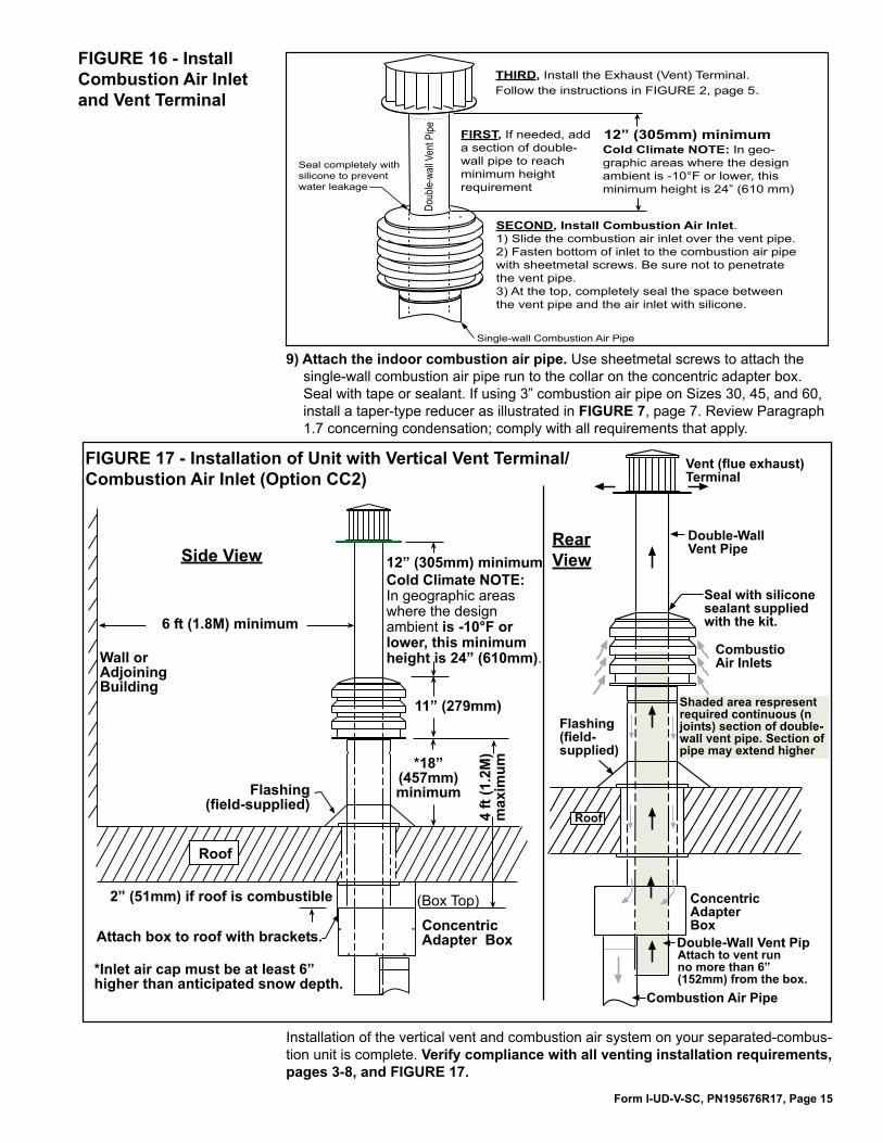
7) On the outside, if an additional section of vent pipe is needed (See FIGURE 16), add it. Make joint according to the pipe manufacturer’s requirements. When vent pipe is the required height, slide the combustion air inlet over the vent pipe and fasten the collar to the combustion air pipe with sheetmetal screws. See FIGURE 16. Seal the opening at the top between the vent pipe and the combustion air inlet with silicone sealant to prevent water leakage.
8) Attach the exhaust (vent) cap. Follow the illustrated instructions in FIGURE 2, page 5.
3.0 VERTICAL VENT INSTRUCTIONS - Option CC2 (cont’d)3.2 Installation Instructions for Vertical Vent/Combustion Air Kit Option CC2 (cont’d)
Form I-UD-V-SC, PN195676R17, Page 15
THIRD, Install the Exhaust (Vent) Terminal. Follow the instructions in FIGURE 2, page 5.
SECOND, Install Combustion Air Inlet. 1) Slide the combustion air inlet over the vent pipe.2) Fasten bottom of inlet to the combustion air pipe with sheetmetal screws. Be sure not to penetrate the vent pipe. 3) At the top, completely seal the space between the vent pipe and the air inlet with silicone.
Doub
le-wa
ll Ven
t Pipe
Cold Climate NOTE: In geo-graphic areas where the design ambient is -10°F or lower, this minimum height is 24” (610 mm)
Single-wall Combustion Air Pipe
FIRST, If needed, add a section of double-wall pipe to reach minimum height requirement
Seal completely with silicone to prevent water leakage
FIGURE 16 - Install Combustion Air Inlet and Vent Terminal
9) Attach the indoor combustion air pipe. Use sheetmetal screws to attach the single-wall combustion air pipe run to the collar on the concentric adapter box. Seal with tape or sealant. If using 3” combustion air pipe on Sizes 30, 45, and 60, install a taper-type reducer as illustrated in FIGURE 7, page 7. Review Paragraph 1.7 concerning condensation; comply with all requirements that apply.
FIGURE 17 - Installation of Unit with Vertical Vent Terminal/Combustion Air Inlet (Option CC2)
Rear ViewSide View
Installation of the vertical vent and combustion air system on your separated-combus-tion unit is complete. Verify compliance with all venting installation requirements, pages 3-8, and FIGURE 17.

Form I-UD-V-SC, PN195676R17, Page 16
www.ReznorHVAC.com; (800) 695-1901 ©2014 Reznor LLC, All rights reserved. Trademark Note: Reznor®, TCORE2®, and
�
are registered in at least the United States.All other trademarks are the property of their respective owners.
Form I-UD-V-SC (12-14)
BBrackets for Attaching the Concentric
Adapter Box to the Roof 13Brackets for Attaching the Concentric
Adapter Box to the Wall 11
CHazards of Chlorine 2Clearance 5, 6Clearances to Horizontal Vent Terminal 10Combustion Air Inlet 15Components 9, 12Condensation 6Pipe Connections at the Concentric Adapter
Box 7
DDiameters of Concentric (outdoor) Pipes 3,
4Concentric Adapter Box Dimensions 7
HHORIZONTAL VENT INSTRUCTIONS -
Option CC6 9Horizontal Vent Terminal 11
IIncreaser 7Inlet air guard 11Installation Instructions for Vertical Vent Kit
13, 14
JJoints 4
LLength from Heater to Concentric Adapter
Box 4
PParts in the Horizontal Vent/Combustion Air
Terminal Package (Option CC6) 9Parts in the Vertical Vent Terminal/Combus-
tion Air Package (Option CC2) 12Pipe Diameter 4Pipe Diameter and Maximum Pipe Length
from Heater to Concentric Adapter Box 4Commercial/Industrial Installation - Pipe
Requirements 3Residential Installation - Pipe Requirements
3
RReducer 7, 8
SSupport 5
TTerminal-end vent pipe 11Type of Pipe 3
VVenting and Combustion Air Requirements 2VENT TERMINAL 9Vent Terminal 15VERTICAL VENT INSTRUCTIONS - Option
CC2 12, 14
INDEX
�