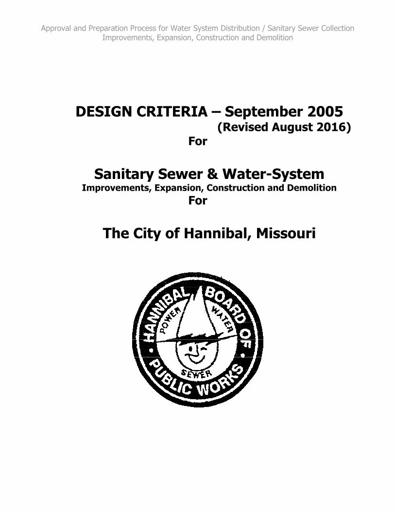
september 2005 (revised august 2016) for sanitary sewer
TRANSCRIPT

City of Hannibal Design Criteria September 2005
(Revised August 2016) For
Sanitary Sewer & Water-System Improvements, Expansion, Construction and Demolition
Approval and Preparation Process for Water System Distribution / Sanitary Sewer Collection Improvements, Expansion, Construction and Demolition
DESIGN CRITERIA – September 2005
(Revised August 2016) For
Sanitary Sewer & Water-System
Improvements, Expansion, Construction and Demolition For
The City of Hannibal, Missouri

Approval and Preparation Process for Water System Distribution / Sanitary Sewer Collection Improvements, Expansion, Construction and Demolition
DESIGN MANUAL
TABLE Of CONTENTS
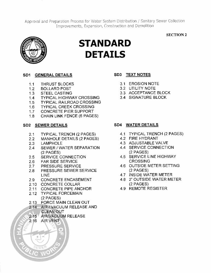
SECTION 1 APPROVAL AND PREPARATION PROCESS IMPROVEMENT, EXPANSION, CONSTRUCTION, DEMOLITION SECTION 2 STANDARD DETAILS
SECTION 3 PLAN REVIEW CHECKLIST
SECTION 4 APPROVED PROJECT OBSERVATION REQUIRED DOCUMENTS SECTION 5 PERMITS AND AUTHORIZATION FORMS
SECTION 6 STANDARD SPECIFICATIONS FOR WATER MAIN CONSTRUCTION
SECTION 7 STANDARD SPECIFICATIONS FOR SANITARY
SEWER MAIN CONSTRUCTION

Approval and Preparation Process for Water System Distribution / Sanitary Sewer Collection Improvements, Expansion, Construction and Demolition
SECTION 1
Approval and Preparation Process
Water System Distribution / Sanitary Sewer Collection Improvements, Expansion, Construction & Demolition SECTION 1 Letter of Introduction
1.0 General 2.0 Preliminary Plan Submittal
3.0 Final Plan Revision / Submittal
4.0 Final Plan Approval / Permits: Water
5.0 Final Plan Approval / Permits: Sewer
6.0 Construction Observation Requirements 7.0 Project Finalization / Acceptance / Authorization for Service

Approval and Preparation Process for Water System Distribution / Sanitary Sewer Collection Improvements, Expansion, Construction and Demolition
Section 1 – Approval and Preparation Process
Section 1: – Approval & Preparation Process S1/1 DC W&S Approval Process 050601 08/11/16
September 01, 2005 RE: Approval and Preparation Process for Water System Distribution / Sanitary Sewer
Collection Improvements, Expansion, Construction and Demolition Dear Design Guide Recipient: The guidelines contained in this manual, shall be used by all parties, involved in the process of preparing, gaining approval, developing, constructing, installing, permitting and legal easement recording; within the service territory jurisdiction of the City of Hannibal, the following: Water System Distribution Improvements Expansion, Construction and Demolition Sanitary Sewer Collection Improvements Expansion, Construction and Demolition Strict adherence to these guidelines will result in a successful project. The City of Hannibal is committed to upholding all laws, rules, regulations and stipulations, as defined by the Federal, State, and local government requirements, as pertaining to the standards, preparation, construction, distribution and maintenance of potable water lines, fire protection lines, and sanitary sewer collection services to serve, as well as protect, the public. The City of Hannibal has made every effort to discover and abide by all regulating rules, laws, and agencies that it is subject to, and have developed this design guide with every attempt to include and abide by the known regulations to date. Should there be found conflict with any rule, regulation, standard or procedure, the higher governing agency shall prevail. This guide does not relieve any responsible party from the applicable requirements of the higher governing agency. This guide shall be periodically reviewed and updated as rules are changed or added. It is the responsibility of the developing parties to ensure that they are using the most current version of this design manual. Should there be any questions or comments please use the following contacts: City Engineer’s office, 320 Broadway, Hannibal MO. 63401, 573-221-0111 Hannibal Board Of Public Works, #3 Industrial Loop, Hannibal MO. 63401, 573-221-8050. Sincerely, ________________________________________ City Engineer, City of Hannibal ________________________________________ General Manager, Hannibal Board of Public Works

Approval and Preparation Process for Water System Distribution / Sanitary Sewer Collection Improvements, Expansion, Construction and Demolition
Section 1 – Approval and Preparation Process
Section 1: – Approval & Preparation Process S1/2 DC W&S Approval Process 050601 08/11/16
1.0 General Within the public utility operating limits jurisdiction of the City of Hannibal, prior to construction or alteration of any public or private, potable water, fire line distribution system, sanitary sewer collection systems, and/or public utility demolition involving the removal of abandoned water or abandoned sanitary sewer service lines/mains, plans must be submitted for prior approval by the appropriate agencies of the city. Submitted plans/drawings are reviewed for general conformity with the City of Hannibal Design Guide Criteria. These drawings are not checked for correctness of design, dimension, or detail. Any absence of details from the plans/drawings or from the review comments does not relieve the contractor or his subcontractor from meeting the requirements of the City of Hannibal Design Guide Criteria, MoDNR regulations, or any other governing agency. 1.1 Definitions - The following definitions shall apply:
1.11 Comment Letter – All formal letters of correspondence between the project parties that specifically detail necessary modifications or any deviations from the plans.
1.12 Demolition – The process of disconnection and removal of existing/abandoned utility facilities according to directives outlined in Section 1, item 2.2 of this document.
1.13 Developer – The project owner, general contractor, and all subcontractors individually or as a whole.
1.14 Improvement, Expansion, Construction and Demolition Approval Process – The first section of this design manual that describes the overall process requirements.
1.15 Location Sketch – A small drawing showing the project location in reference to the City of Hannibal.
1.16 Mains – Underground primary water distribution lines or primary sanitary sewer collection lines that are operated and maintained by the City of Hannibal.
1.17 MoDNR - Missouri Department of Natural Resources 1.18 OSHA - Occupational Safety and Health Administration 1.19 PE - Professional Engineer 1.20 Public Utility Operating Limit Jurisdiction
This includes accepted public utility facilities, within the boundaries of the City of Hannibal jurisdiction territory limits, as well as particular individual agreements under special conditions, as agreed to with the bordering utility agency territories, so as to avoid duplication of vital services and/or to resolve any special utility needs as unique circumstances may require.
1.21 Record Drawings – All documentation and accurate drawing plan representation of the final condition of the project objectives. Commonly referred to as the “As Built” plans.
1.22 Redlined Drawings - A marked-up set of plans with needed modifications punctuated in bold or colored, most often red.
1.23 Sealed Plans / Plats – Reflects a seal that is affixed to all final plans. Survey information (including easements) are sealed by a Professional Land Surveyor and engineering is sealed by a Professional Engineer

Approval and Preparation Process for Water System Distribution / Sanitary Sewer Collection Improvements, Expansion, Construction and Demolition
Section 1 – Approval and Preparation Process
Section 1: – Approval & Preparation Process S1/3 DC W&S Approval Process 050601 08/11/16
1.2 Abbreviations - The following abbreviations shall be used:
1.21 City of Hannibal / Board of Public Works - BPW 1.22 City of Hannibal / Director of Public Works - City Engineer 1.23 City of Hannibal / BPW Design Criteria Manual - Criteria 1.24 A professional engineer licensed in Missouri – PE 1.25 Approved Construction Observation Engineering Firm – Firm 1.26 Occupational Safety and Health Administration – OSHA 1.27 Improvement, Expansion, Construction & Demolition Approval Process – Process 1.28 Approved Construction Observation Representative - Representative 1.29 Sanitary Sewer - SS
2.0 Preliminary Plan Submittal
2.1 General Submit to the City Engineer, a minimum of three (3) sets of plans/plats. They should be clearly marked Preliminary Plans prepared by a PE registered in the State of Missouri. Minimally the plans shall include: 2.11 An overall project plan or site layout, showing all of the existing and proposed
utility improvements. 2.12 An acceptance signature block on the cover sheet. The block signature lines shall
contain the following: The City Engineer, The General Manager (or representative) of the Board of Public Works, and the plan design Professional Engineer, and the Chief of the Hannibal Fire Department. (For Example, See Section 2, Standard Details, Text Notes)
2.13 A project Location Sketch on the cover page. 2.14 The plans shall indicate all existing water and/or sewer facilities, and identify any
that are in conflict with the proposed project improvements. Should existing utilities require relocation, the PE shall provide a proposed utility relocation plan for approval. The relocation of the existing water and sewer utilities shall be incorporated into the overall construction project as well as appropriate demolition plan of abandoned utility facilities, as required. The developer shall schedule and pay all costs of the utility relocation, including acquiring additional easements if necessary.
2.2 Demolition Criteria
BPW personnel shall make the physical disconnection of any existing utility that is to be demolished, abandoned or relocated, including service connections as well as mains. 2.21 When required, demolition shall be considered during the planning process with
drawings and notations on the plans as necessary. 2.22 The developer is responsible to expose the demolition portion of utility
main/service disconnection points, as required according to OSHA standards, and all manpower, materials and equipment are to be provided by the contractor.
2.23 The developer is responsible for providing appropriate trench worker protection when required according to OSHA standards.
2.24 The developer shall give a minimum of 2 working days notice to BPW for scheduling the disconnection of the exposed disconnection points.

Approval and Preparation Process for Water System Distribution / Sanitary Sewer Collection Improvements, Expansion, Construction and Demolition
Section 1 – Approval and Preparation Process
Section 1: – Approval & Preparation Process S1/4 DC W&S Approval Process 050601 08/11/16
Any overtime worked by BPW personnel will be charged to developer at BPW standard overtime labor rate.
2.25 After the BPW has completed the disconnections and given approval, the developer is responsible for backfilling, replacing and/or restoring any improvements disturbed and/or damaged during the demolition process such as street, sidewalk, and retaining wall repair or replacement. All repairs shall be in accordance with the building codes of the City of Hannibal. All developer’s costs incurred in the demolition process shall be borne by the developer.
2.3 Preliminary Plan Review Comments
The City Engineer will consolidate all preliminary plan review comments and forward them to the PE in the form of a comment letter with redlined drawings. Note: Additional items may be identified during the review of the final plans. The review process does not necessarily relieve the PE of professional responsibility, nor does it relieve any of the requirements of the Criteria.
3.0 Final Plan Revision / Submittal
3.1 Final Plan 3.11 With PE’s official seal and current date stamp, submit three (3) sets of final revised
construction plans to the City Engineer. 3.12 Cover Sheet Routing / Approval Signatures: After all design and needed
modifications are complete, the PE shall route an additional cover and any modified sheets, for approval signatures. Once all signatures are obtained, a copy of the approved cover shall be returned to the PE and shall be copied for use as the cover of all final sets of approved water and/or sewer plans.
3.13 For water main construction, a completed Application For Water Main Construction Permit shall be completed and submitted to BPW. (See Section 5, Form P1)
3.14 For sewer main construction, a completed MoDNR Application For Construction Permit For Sewer Extension shall be completed and submitted to the City Engineer. (See Section 5, Form P5)
3.15 When the project plan is developed electronically, the BPW desires an electronic copy of the final plan, or at minimum the particular portions or sheets covering the interests of the City Engineer’s office, and BPW. Electronic files may be accepted in .mxd, .dwg, or .dxf file format. (See also, Section 1, Item 7.131c)
4.0 Final Plans Approval / Permits: Water 4.1 Submittal of BPW Construction Permit: Water Main
For water main construction the PE shall submit: 4.11 (Repeated) A copy of the completed Application For Water Main Construction
Permit (See Section 5, Form P1) 4.12 A legally recorded copy of the necessary project utility easements, (i.e. subdivision
plat, written easement, etc.)
Approval and Preparation Process for Water System Distribution / Sanitary Sewer Collection Improvements, Expansion, Construction and Demolition
Section 1 – Approval and Preparation Process
Section 1: – Approval & Preparation Process S1/5 DC W&S Approval Process 050601 08/11/16
Exception: With prior approval, large commercial and industrial projects may be able to start construction without legally recording permanent easements however no service connection will be allowed without legally recorded easements submitted to the BPW. (See also Section 1, Item 7.0) 4.12.1 Upon approval of the completed plans and documents, the City Engineer
shall issue a Construction Permit – Water Main. (Permit is good for 1 year) (See Section 5, Form P2)
5.0 Final Plans Approval / Permits: Sewer
5.1 Approval of MoDNR Construction Permits: Sewer Main Upon receipt of the MoDNR Construction Permit, the PE shall forward to the City Engineer and BPW: 5.11 Copies of the approved MoDNR Construction Permit
(Permit good for 1 year and can be extended 1 time for and additional 6 months if the request is submitted at least 30 days prior to original expiration.) Under no circumstances shall construction of sewer improvements begin prior to the issuance of a MoDNR Construction Permit.
5.12 A legally recorded copy of the necessary project utility easements, (i.e. subdivision plat, written easement, etc.) Exception: With prior approval, large commercial and industrial projects may be able to start construction without legally recording permanent easements however no service connection will be allowed without legally recorded easements submitted to the BPW. (See also Section 1, Item 7.0)
6.0 Construction Observation Requirements
All construction must be inspected, certified as compliant with the plans specification and the Criteria, by a PE licensed to practice in the State of Missouri. Upon receipt of all required construction permits and recorded easements, the developer may proceed by retaining construction observation as outlined in Item 6.1. The Construction Contact Information form (See Section 4, FORM-C1,) must be completed and submitted to the City Engineer and BPW, a minimum of 2 working days prior to any construction activities. 6.1 Approved Construction Observation Representative
An experienced Representative shall be utilized to ensure that all construction and improvements are accomplished according to the approved plans. The Criteria requires that a Representative be retained to conduct regular construction observations during the construction of sewer and/or water mains. The Firm utilized must satisfy the requirements of the Criteria concerning the qualifications of the assigned Representative as described below. 6.11 The Representative shall be predefined as provided by an engineering firm that has
requested and received approval in writing, to represent the BPW during the project construction. The approval process will not necessarily take place for each project. A list of the minimum duties / responsibilities are: 6.111 The Firm fully understands the requirements outlined in the Criteria. 6.112 The Firm can professionally apply those requirements to the construction
techniques at the project site.

Approval and Preparation Process for Water System Distribution / Sanitary Sewer Collection Improvements, Expansion, Construction and Demolition
Section 1 – Approval and Preparation Process
Section 1: – Approval & Preparation Process S1/6 DC W&S Approval Process 050601 08/11/16
6.113 The Firm is expected to manage the project observation ensuring that the BPW receives regular communication concerning the project status and progress of the improvements.
6.114 The Firm must have a PE on staff, registered in the State of Missouri, providing all necessary certifications.
6.115 To avoid conflict of interest, the Developer cannot also act as the Representative.
6.2 Safety
The contractor is expected to abide by all applicable OSHA construction guidelines. 6.21 For pedestrian and traffic safety, the contractor shall follow MoDOT guidelines
Traffic Control For Field Operations. 6.211 Should the construction interfere with pedestrian or vehicular traffic, the PE
and/or developer shall provide a traffic control plan and submit it to the City Engineer for approval, prior to beginning any construction activities in traffic areas.
6.3 Water Distribution Line Installations The following test requirements apply to all water main installations and modifications to the BPW water distribution system. A minimum of 2 working days notice shall be required prior to all testing. 6.31 Waterline Pressure Test
Upon completion of the new water main installation a Waterline Pressure Test Report shall be performed under the direct observation of the Representative. The Representative shall complete FORM-C4 (See Section 4, Form C4) for each waterline pressure test required.
6.32 Filling, Flushing and Disinfections of New Water Main Filling, flushing and disinfections of new water main are to be conducted under the direct supervision of BPW. Water for testing shall be provided by the BPW. 6.321 All manpower, materials and equipment are to be provided by the
contractor. 6.322 The BPW must be notified a minimum of 2 working days prior to the work
being performed so as to assign and schedule available BPW labor. 6.323 Should the BPW worker be requested to work during BPW non-business
hours, the developer shall incur the additional labor costs at the BPW current rate for overtime.
6.33 Water Service Taps Water service taps are to be completed by the BPW. 6.331 Tap fees must be paid at the BPW office prior to the work being performed. 6.332 The developer is responsible for exposing and backfilling the water main. 6.333 The size of the excavation is to be in accordance with the standards of
OSHA. 6.334 The developer is responsible for providing appropriate trench worker
protection when required, according to OSHA standards. 6.335 The BPW will provide the manpower, materials and equipment to conduct
the tap only.

Approval and Preparation Process for Water System Distribution / Sanitary Sewer Collection Improvements, Expansion, Construction and Demolition
Section 1 – Approval and Preparation Process
Section 1: – Approval & Preparation Process S1/7 DC W&S Approval Process 050601 08/11/16
6.34 Cross-Connections Control and Backflow Prevention The City of Hannibal has adopted and approved City Ordinance #3661 pertaining to Cross-Connections Control and Backflow Prevention. When applicable all construction plans shall have the following objectives: 6.341 To protect the public potable water supply from the possibility of
contamination by isolating within the consumer’s premises contaminants or pollutants, which could backflow into the public water system.
6.342 To eliminate or control cross connections, actual or potential, between the consumer’s in-plant potable water system and non-potable water systems, plumbing fixtures or industrial piping systems.
6.343 To provide means whereby a consumer may be able to use an auxiliary water supply for industrial or fire protection purposed without the danger of contaminating the public water supply.
6.344 To provide for a continuing program of control, which will systematically and effectively control all actual or potential cross-connections, which may be established in the future.
6.35 See Section 6 of this Document for “Standard Specifications for Water Main Construction.”
6.4 Sanitary Sewer Collection System Installations
The following general guidelines apply to all SS line installations and modifications to the SS collection system.
6.41 Gravity Sanitary Sewer System Test Upon completion of the new sewer main/manhole installation a Gravity Sewer Test shall be performed under the direct observation of the Representative. The Representative shall complete FORM-C2, Gravity Sewer Test Report (See Section 4, FORM-C2) for each test required.
6.42 Manhole Ex-filtration Vacuum Test Upon installation of each new manhole a Manhole Exfiltration Vacuum Test shall be performed under the direct observation of the Representative. The Representative shall complete FORM-C3 (See Section 4, FORM-C3) for each new manhole.
6.43 Sanitary Sewer Service Taps SS service taps are to be completed by the BPW. 6.431 Tap fees must be paid prior to the work being performed. 6.432 The developer is responsible for exposing, and backfilling the SS main. 6.433 The size of the excavation is to be in accordance with OSHA standards 6.434 The developer is responsible for providing appropriate OSHA standard
trench worker protection when required. 6.434 The BPW will provide the manpower, materials and equipment to conduct
the tap only. 6.44 See Section 7 of this Document for “Standard Specifications for
Sanitary Sewer Main Construction.”

Approval and Preparation Process for Water System Distribution / Sanitary Sewer Collection Improvements, Expansion, Construction and Demolition
Section 1 – Approval and Preparation Process
Section 1: – Approval & Preparation Process S1/8 DC W&S Approval Process 050601 08/11/16
7.0 Project Finalizations / Acceptance / Authorization For Service 7.1 Required Documentation Submittals
A list of the minimum documented activities that are to take place during construction and minimum information that is to be recorded can be found on FORM-I1, FORM- I2 & FORM-I3 of Section 4. Upon completion of the construction and all required testing, the PE shall submit the following information to the City Engineer: 7.11 A copy of the Representative’s project observation logs. (See Section 4, FORM-I1
and FORM-I2) 7.12 One (1) copy of all test reports. (See Section 4, FORM-C2, FORM-C3, and FORM-C4) 7.13 Two (2) copies of the Record Drawings. (See Section 4, FORM-I1 and FORM-I2)
7.131 All changes, deviations or modifications to the original plans shall be clearly shown on a copy of the original plans which when completed are clearly marked Record Drawing on each page, along with a final revision date. a. This notation shall contain the date that the corrections were completed. b. The initials of the person making the changes. c. An electronic version may be updated, properly annotated, and used for
this requirement. d. All elevations, angles, dimensions, alignments, etc. shall be field
verified with corrected markings and annotations clearly shown on the Record Drawings to accurately reflect any necessary construction variations.
e. Record Drawings must be submitted regardless whether any changes were made to the original plans or not.
f. Subdivision plats: Prior to final delivery of new subdivision utilities, all subdivision plats must have been formally approved by the City of Hannibal and properly recorded according to law, showing the book and page of the legal recording on the plat or plan cover. A copy of this recorded instrument must accompany public utility improvement plans for appropriate easement verification prior to delivery of services.
7.132 Should the project plan be developed electronically, the BPW desires an
electronic copy of the final approved plan, at minimum the particular portions or sheets covering the interest of the City of Hannibal. Electronic files can be accepted in “.mxd” “.dwg” or “.dxf” file format.
7.14 One (1) copy of the Application for Letter of Authorization for Water Service
(See Section 5, FORM P3) 7.15 One (1) copy of the Application for Letter of Authorization for Sewer Extension
(See Section 5, FORM P7)
7.2 Authorization to Place Improvements Into Service 7.21 Water Improvements
Upon receipt, review and approval of the PE submittals, the BPW will issue a Letter of Authorization for Service - Operating Permit (See Section 5, FORM P4) to the PE authorizing the new water lines to be placed into service.
Approval and Preparation Process for Water System Distribution / Sanitary Sewer Collection Improvements, Expansion, Construction and Demolition
Section 1 – Approval and Preparation Process
Section 1: – Approval & Preparation Process S1/9 DC W&S Approval Process 050601 08/11/16
No service connections (taps) shall be completed until the BPW has authorized the new line to be placed into service.
7.22 Sewer Improvements 7.221 Upon receipt, review and approval of the design engineer’s submittals, the
BPW will issue a Letter of Authorization (See Section 5, P4) for the DE to submit all test results and record drawings to MoDNR. Upon the approval of test results, new SS connections (taps) may be allowed.
7.222 Upon MoDNR review and approval of the submittals, a Letter of Authorization - Operating Permit shall be issued to the BPW.
END OF SECTION


Approval and Preparation Process for Water System Distribution / Sanitary Sewer Collection Improvements, Expansion, Construction and Demolition
SECTION 3
PLAN REVIEW
CHECKLIST
R1 CHECK LIST FOR REVIEW OF GRAVITY SEWER LINE
R2 CHECK LIST FOR REVIEW OF WATER LINE PLANS
R3 CHECK LIST FOR REVIEW OF SUBDIVISION PLATS
R4 CHECK LIST FOR REVIEW OF LIFT STATIONS

Approval and Preparation Process for Water System Distribution / Sanitary Sewer Collection Improvements, Expansion, Construction and Demolition
Section 3 – Plan review Checklists
CITY OF HANNIBAL BOARD OF PUBLIC WORKS
FORM – R1 REVIEW CHECK LIST FOR GRAVITY SEWER PLANS
DEVELOPER PROJECT NAME
ADDRESS
DESIGN ENGINEER DATE SUBMITTED
HBPW REVIEWER DATE REVIEWED
PLAN VIEW: 1 Location and Size of Existing Sewer 2. If New Manhole on Existing Line:
a. Distance Between Existing Manholes b. Flowline Elevations at Existing Manholes c. Distance from Existing Manhole to Proposed Manhole
d. Flowline Elevation at Proposed Manhole 3. Angles Between Line Sections at all Manholes 4. Location of Sewer Services (if proposed) 5. Location, Size, Length and Angle to all Stub-outs (if proposed) 6. Location, Size and Labels for Easements 7. Topographic Features and Existing Utilities 8. Existing and Proposed Property/Lot Lines 9. Adjacent Property Names (Name and Address) 10. North Arrow 11. Graphic Scale 12. Legend
13. Benchmark Description, Location and Elevation (NAVD 1988, NGVD 1929, Mean Seal Level 1912, Memphis Datum or MoDOT)
14. Lot Numbers 15. Road/Street Names 16. Location Map
Section 3: Plan Review Checklists – Form R1 S3R1.1/1 Section 3 Form R1 Gravity Sewer Plans.doc 10/27/05
Approval and Preparation Process for Water System Distribution / Sanitary Sewer Collection Improvements, Expansion, Construction and Demolition
Section 3 – Plan review Checklists
Section 3: Plan Review Checklists – Form R1 S3R1.1/2 10/27/05
PROFILE VIEW: 1. Size and Invert and Top Elevation of Existing Sewer (both sides of tie-in) 2. Invert and Top Elevations at all Manholes 3. Distance, Percent of Slope, Size and Pipe Material for Each Line Section 4. Existing Ground Profile with Label 5. Location, Size and Length of Casing Pipe (if proposed) 6. Location, Size and Length of Aerial Pipe (if proposed) 7. Location, Footing Elevation and Distance Between Piers (if proposed) 8. Location of Existing Utilities to be Crossed and/or Paralleled 9. Location and Length of Concrete Encasement (if proposed) 10. Special Backfill Type and Length (I.E. Granular, Flowable, etc) (if proposed) 11. Surface Repair (if not covered in trench detail) PLAN/PROFILE REVIEW GENERAL COMMENTS: These plans were reviewed for general conformity with the HBPW Master plan and HBPW Design Guide requirements. These drawings were not checked for correctness of dimension or detail, it is not our responsibility to insure the accuracy of the dimensions and their correlation on the job site. Any absence of details from the drawings or review comments does not relieve the developer from meeting the requirements of the HBPW Design Guide. Signature Title
Section 3 Form R1 Gravity Sewer Plans.doc

Approval and Preparation Process for Water System Distribution / Sanitary Sewer Collection Improvements, Expansion, Construction and Demolition
Section 3 – Plan review Checklists
Section 3: Plan Review Checklists – Form R2 S3R2.1/1 Section 3 Form R2 Water Line Plans.doc 10/27/05
CITY OF HANNIBAL BOARD OF PUBLIC WORKS
FORM – R2 REVIEW CHECK LIST FOR WATER LINE PLANS DEVELOPER PROJECT NAME
ADDRESS
DESIGN ENGINEER DATE SUBMITTED
HBPW REVIEWER DATE REVIEWED
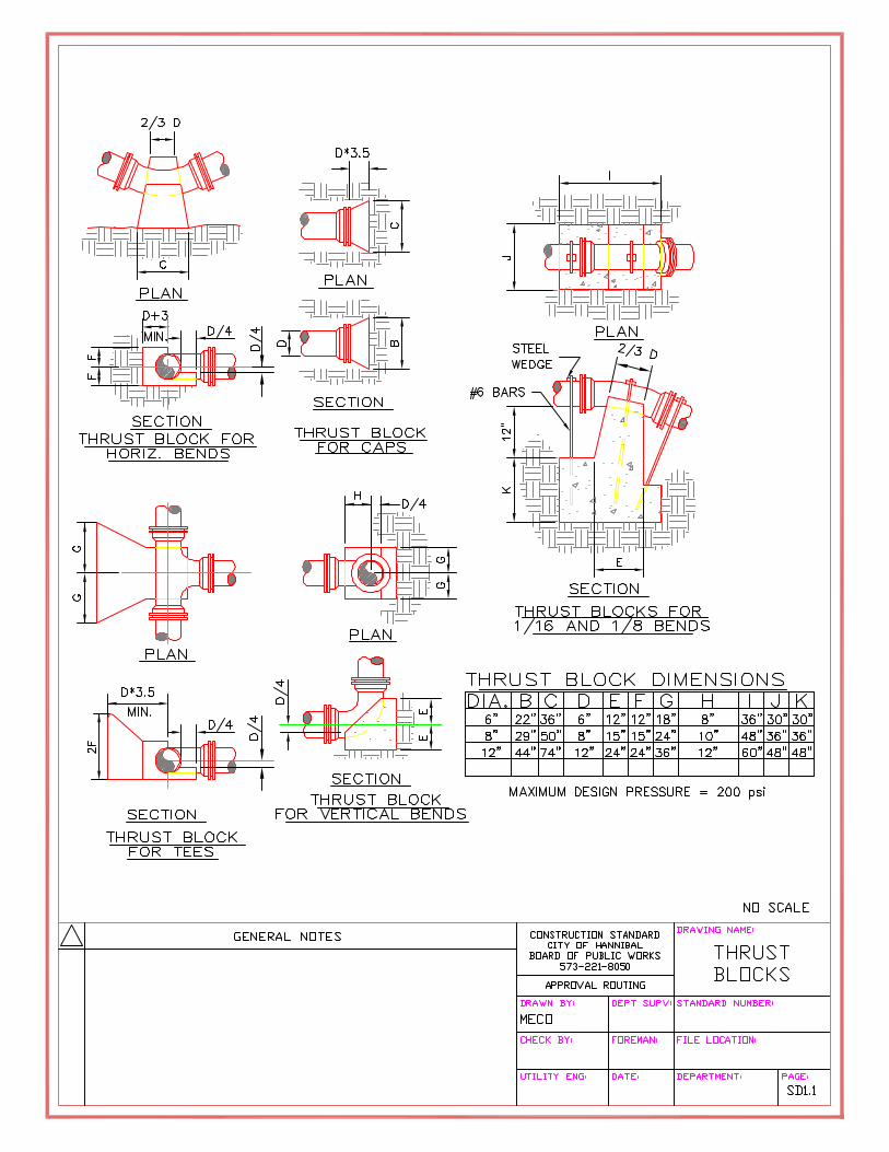
ALL WATER PLANS SHALL SHOW THE FOLLOWING: (ADDITIONAL INFORMATION MAY BE REQUIRED) 1. Property, Lot Lines, Right-of-way 2. Adjacent Property Owners (names + addresses) 3. Location and Size of Existing Main 4. Location, Size and Labels for Easements 5. Method of Connection to Existing Main 6. Location, Size and Material for Proposed Mains 7. Location, Size and Material for Service Lines (if proposed) 8. Location of Meters (if proposed) 9. Topographic Features and Existing Utilities 10. North Arrow 11. Graphic Scale 12. Road/Street Names 13. Dimensions to Locate Main 14. Notes on all Fittings, Valves, Hydrants, Thrust Blocks, etc. 15. Materials List 16. Location Map
Approval and Preparation Process for Water System Distribution / Sanitary Sewer Collection Improvements, Expansion, Construction and Demolition
Section 3 – Plan review Checklists
Section 3: Plan Review Checklists – Form R2 S3R2.1/2 Section 3 Form R2 Water Line Plans.doc 10/27/05
REVIEW GENERAL COMMENTS: These plans were reviewed for general conformity with the HBPW Master plan and HBPW Design Guide requirements. These drawings were not checked for correctness of dimension or detail, it is not our responsibility to insure the accuracy of the dimensions and their correlation on the job site. Any absence of details from the drawings or review comments does not relieve the developer from meeting the requirements of the HBPW Design Guide. Signature Title

Approval and Preparation Process for Water System Distribution / Sanitary Sewer Collection Improvements, Expansion, Construction and Demolition
Section 3 – Plan review Checklists
Section 3: Plan Review Checklists – Form R3 S3R3.1/1 Section 3 Form R3 Subdivision Plans-Plats.doc 10/27/05
FORM – R3 REVIEW CHECK LIST FOR SUBDIVISION PLANS / PLATS DEVELOPER DEVELOPMENT NAME
ADDRESS
DESIGN ENGINEER DATE SUBMITTED
HBPW REVIEWER DATE REVIEWED
PLAN VIEW: 1 Name of the Subdivision 2. Legal Description of the Property 3. Dedication of Streets and Easements 4. Signature Block for Property Owners a. Name: _____________________________________________________________ b. Title: ______________________________________________________________ c. Address: ___________________________________________________________ d. Phone Number: ______________________________________________________ 5. Notary Certification 6. Location Map 7. Acceptance Certification for City Entities 8. Bearing and Distance on all Lot Lines (clockwise direction) a. Bearings can be Deleted on Intermediate Lot Lines if Lines are Parallel. b. Bearings can be Deleted on Lot Lines if Lines are parallel to Road Centerlines. 9. Bearing and Distance on All Road Centerlines, Curve Data Same. 10. Street Names, Width and Dimensions 11. Label, Width and Location of Easements 12. Lot Numbers 13. Adjoining Property Owners (name and address) 14. Name of Client for Who Survey Was Made for and Grantor or Grantee Name 15. Quarter Section/Quarter-Quarter Section (or subdivision name with lot and block) 16. Township/Range/Section 17. City/County/State 18. North Arrow
CITY OF HANNIBAL BOARD OF PUBLIC WORKS

Approval and Preparation Process for Water System Distribution / Sanitary Sewer Collection Improvements, Expansion, Construction and Demolition
Section 3 – Plan review Checklists
Section 3: Plan Review Checklists – Form R3 S3R3.1/2 Section 3 Form R3 Subdivision Plans-Plats.doc 10/27/05
19. Graphic or Written Scale 20. Horizontal Distance of all Surveyed Lines 21. Three Decimal Places in City/Subdivision 22. All controlling Corners Shown 23. Legend 24. Survey Certification (By Missouri Registered Land Surveyor) REVIEW GENERAL COMMENTS: These plans were reviewed for general conformity with the HBPW Master plan and HBPW Design Guide requirements. These drawings were not checked for correctness of dimension or detail, it is not our responsibility to insure the accuracy of the dimensions and their correlation on the job site. Any absence of details from the drawings or review comments does not relieve the developer from meeting the requirements of the HBPW Design Guide. Signature Title

Approval and Preparation Process for Water System Distribution / Sanitary Sewer Collection Improvements, Expansion, Construction and Demolition
Section 3 – Plan review Checklists
Section 3: Plan Review Checklists – Form R4 S3R4.1/1 Section 3 Form R4 Lift Stations.doc 10/27/05
FORM – R4 REVIEW CHECK LIST FOR LIFT STATIONSDEVELOPER DEVELOPMENT NAME
ADDRESS
DESIGN ENGINEER DATE SUBMITTED
HBPW REVIEWER DATE REVIEWED
PLAN VIEW: 1 Location and size of proposed sewers (at or near lift station) 2. Site Plan (all items should be labeled, but are “if required”)
a. Lift Station b. Piping (location, size direction of flow)
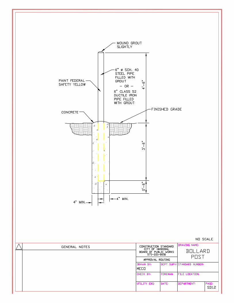
c. Control Panel d. Power Source e. Work Light f. Hoist g. Fence with gate h. Warning Signs i. Emergency contact information sign j. Access road with turn around k. Bollards 3. Angles between last line section and lift station. 4. Location, size and labels for easements 5. Topographic features and existing utilities 6. Existing and proposed property/lot lines 7. Proposed water mains 8. North Arrow 9. Graphic Scale 10. Legend
11. Benchmark description, location and elevation (NAVD 1988, NGVD 1929, Mean Seal Level 1912, Memphis Datum or MoDOT)
12. Adjoining Lot Numbers 13. Road/Street Names 15. Size of embankment protection (if required) 17. Complete title block information 18. Sewer and water separation note (PWSD #1 of Lincoln County)
CITY OF HANNIBAL BOARD OF PUBLIC WORKS

Approval and Preparation Process for Water System Distribution / Sanitary Sewer Collection Improvements, Expansion, Construction and Demolition
Section 3 – Plan review Checklists
Section 3: Plan Review Checklists – Form R4 S3R4.1/2 Section 3 Form R4 Lift Stations.doc 10/27/05
PROFILE VIEW: 1. Size and invert of proposed sewer entering lift station 2. Top and flow line elevation at last manhole prior to lift station 3. Distance, percent of slope, size and pipe material for line from manhole to lift station 4. Existing ground profile with label. 5. Location of existing utilities to be crossed and/or paralleled. 6. Size of embankment protection (if required) 7. Special backfill type and length (I.E. granular, flowable, etc) (if required) 8. Pump manufacturer and model number 9. Float Elevations 10. Vault size and material 11. Discharge point elevation and detail PROBLEMS ENCOUNTERED AND RESOLUTION OF PROBLEMS DURING PLAN/PROFILE REVIEW:
Signature Title

Approval and Preparation Process for Water System Distribution / Sanitary Sewer Collection Improvements, Expansion, Construction and Demolition
SECTION 4
APPROVED PROJECT
OBSERVATION Required Documentation
C1 CONSTRUCTION CONTACT INFORMATION
C2 GRAVITY SEWER TEST REPORT
C3 MANHOLE EXFILTRATION VACUUM TEST
C4 WATERLINE PRESSURE TEST REPORT
I1 CONSTRUCTION OBSERVATION - GRAVITY SEWER LINE
I2 CONSTRUCTION OBSERVATION – WATERLINE
I3 CONSTRUCTION OBSERVATION – SANITARY SEWER FORCEMAIN

Approval and Preparation Process for Water System Distribution / Sanitary Sewer Collection Improvements, Expansion, Construction and Demolition
Section 4 – Approved Project Observation, Required Documentation
CITY OF HANNIBAL BOARD OF PUBLIC WORKS
FORM – C1 CONSTRUCTION CONTACT INFORMATION
DEVELOPER PROJECT NAME
ADDRESS
DESIGN ENGINEER DATE SUBMITTED
This form shall be completed and submitted to the city Engineer/Director of Public Works prior to any work being completed on sewer or water project.
Approved Project Representative Name: _________________________________________________________________________ Phone Number: __________________________________________________________________ Field Representative Name: ________________________________________________________ Mobile Phone Number: ___________________________________________________________ Contractor Name: _________________________________________________________________________ Phone Number: __________________________________________________________________ Project Foreman’s Name: __________________________________________________________ Mobile Phone Number: ___________________________________________________________ Expected Start Date: Expected Testing Date: Expected Completion Date:
Section 4: Required Documentation – Form C1 S4C1.1/1 Section 4 Form C1 Construction Contact Information.doc 10/27/05

Approval and Preparation Process for Water System DistributionSanitary Sewer Collection Improvements, Expansion, Construction and Demolition
Section 4 - Approved Project Observation, Required Documentation
FORM-C2GRAVITY SEWER TEST REPORT
DEVELOPER: PROJECT NAME:ADDRESS:
DESIGN ENGINEER: DATE SUBMITTED:
TEST DATA AND CALCULATIONSLocation of Test:
Length of Sewerline (ft):
Inside Diameter of Sewerline (in):
Outside Diameter of Mandrel (in):
Duration of Test (from spec): MIN. SEC.
Required Pressure at Start of Test (psi):
Allowable Pressure Loss During Test (psi):
Required Pressure at End of Test (psi):
PRESSURE TEST:
Time @ Start of Test: Pressure @ Start of Test:
Time @ End of Test: Pressure @ End of Test:
Pressure Lost During Test:
PASS FAIL
MANDREL TEST: LAMP TEST:
PASS FAIL PASS FAIL
NOTES:
Date:
Witnessed:Project Representative Contractor's Representative
CITY OF HANNIBAL BOARD OF PUBLIC WORKS
Section 4 Form C2 Gravity Sewer Test Rpt.xls Section 4: Required Documentation (10/27/2005)
Approval and Preparation Process for Water System Distribution / Sanitary Sewer Collection Improvements, Expansion, Construction and Demolition
Section 4 – Approved Project Observation, Required Documentation
Section 4: Required Documentation – Form C3 S4C3.1/1 Section 4 Form C3 Manhole Exfiltration Vacuum Test.doc 10/27/05
CITY OF HANNIBAL BOARD OF PUBLIC WORKS
FORM – C3 MANHOLE EXFILTRATION VACUUM TEST DEVELOPER PROJECT NAME
ADDRESS
DESIGN ENGINEER DATE SUBMITTED
Manhole
# Manhole
I.D. Manhole Height
Test Duration
Start Vacuum
End Vacuum Date Passed
Date: Witnessed: Project Representative Contractor’s Representative

Approval and Preparation Process for Water System DistributionSanitary Sewer Collection Improvements, Expansion, Construction and Demolition
Section 4 - Approved Project Observation, Required Documentation
FORM C4
WATERLINE PRESSURE TEST REPORT
DEVELOPER: PROJECT NAME:ADDRESS:
DESIGN ENGINEER: DATE SUBMITTED:
Location of Test:
Length of Waterline (Feet):multiplied by
Inside Diameter of Waterline (Inches):multiplied by
Duration of Test (Hours):multiplied by
Conversion Factor: 0.000078914*equals
Allowable Water Loss (Gallons)=
Waterline Pressure Prior to Test (psi):
Waterline Test Pressure (Greater of 1.5 times Line Pressure
or Pressure Rating of Pipe in PSI):
Amount of Water Added During Test (Gallons):
RESULTS OF PRESSURE TEST (PASS OR FAIL):
*Based upon an allowable water loss of 10 gallons per inch diameter per mile of pipe per 24 hours.
Date:
Witnessed:Project Representative Contractor's Representative
CITY OF HANNIBAL BOARD OF PUBLIC WORKS
PRESSURE TEST DATA AND CALCULATIONS
Section 4 Form C4 Waterline Pressure Test Report.xlsSection 4: Required Documentation - Form C4 10/27/2005

Approval and Preparation Process for Water System Distribution / Sanitary Sewer Collection Improvements, Expansion, Construction and Demolition
Section 4 – Approved Project Observation, Required Documentation
Section 4: Required Documentation – Form I1 S4I1.1/1 Section 4 Form I1 Construction Observation Gravity Sewer Line.doc 10/27/05
CITY OF HANNIBAL BOARD OF PUBLIC WORKS
FORM – I1 Construction Observation Gravity Sewer Line
I. DAILY DIARY (IN INK): The approved project representative on a daily basis shall record the
following information: A. Enter the Following Items on a Daily Basis: 1. Date 2. Weather 3. Contractor’s work force. 4. Contractor’s equipment on site. 5. General observation of work in progress and location of work. 6. Damage to any existing utilities or private property. 7. Conversations with contractor or design engineer relative to project. 8. Visitors on site. II. MATERIALS: The field representative shall observe the following items prior to their
installation. A. Verify that materials delivered to job site comply with approved shop drawings. B. Check materials for damages. C. Pipe 1. Inspection a. Visual inspection on truck (any apparent damage, broken bands, broken pipe, etc.). b. Correct pipe (compare pipe labeling to shop drawings). c. Damage (discoloration, deformation, broken or damaged spigots or bells). 2. Unloading (was pipe unloaded by hand, mechanical means or allowed to droop to the ground). 3. Storing (is it stored flat, left in original bundles, covered, stored away from grease, oil and heat). 4. Hauling (flat, supported in multiple locations, secured if not stringing). D. Manholes 1. Inspection a. Size (correct diameter, correct height) b. Correct manholes (compare to shop drawings, step holes, damp-proofing).
c. Damage (chipped edges, cracks, “spider webbing” a minimum amount of cracks are
allowed per ASTM). d. A-locs installed (A-locs cast into manholes). 2. Unloading (was pre-casters lift holes used to move manholes). III. INSTALLATION: In addition to the information listed above, the field representative shall note
in the Daily Diary any discrepancies in the following.

Approval and Preparation Process for Water System Distribution / Sanitary Sewer Collection Improvements, Expansion, Construction and Demolition
Section 4 – Approved Project Observation, Required Documentation
Section 4: Required Documentation – Form I1 S4I1.1/2 Section 4 Form I1 Construction Observation Gravity Sewer Line.doc 10/27/05
A. Width (within minimum and maximum limits as set out on details). B. Supported trench (was trench box, sheeting, bracing, jacks, etc. used in the trench). C. Unstable trench walls (do trench walls collapse against trench box). D. Water conditions (was trench dewatered, is water standing in the trench, is water entering the pipe). E. Trench bottom (is the trench bottom stable, bedding material compacted to correct thickness, holes made to accept pipe bells). F. Over excavation (was trench bottom excavated more than 6” but less than 12” below the bottom of the pipe, was over excavation filled with compacted granular bedding material). G. Unstable trench bottom (is trench bottom unstable, did the engineer evaluate conditions, was over excavation required, was stable trench bottom established as directed by the engineer). H. Rock sub grade (are ledge rock, boulders or large stones visible in the trench bottom). I. Bedding (is the proper bedding material placed and COMPACTED to the correct grade, is bedded depressed to allow for the pipe bells). J. Pipe Placement 1. Spigot cleaned (for cut pipe-spigot bevel must be re-established). 2. Gasket checked. 3. Pipe lowered into trench (not dropped). 4. Gasket lubricated. 5. Insertion mark within 1” of bell. K. Check laser equipment (is it properly positioned, is the correct percent of grade set). L. Haunching (up to spring line of pipe – installed and compacted to eliminate voids under pipe). M. Initial backfill (placed and compacted). N. Final backfill (clear of rock and debris, compacted in lift if required). O. Manholes 1. Excavation (was hole dug to the correct depth, if over excavated – must be filled with compacted crushed stone). 2. Crushed stone base (was base rock COMPACTED to the correct grade). 3. Base section set (to the correct elevation and orientation). 4. Riser sections (installed using 2 strips of butyl mastic, step holes aligned). 5. Pipes correctly inserted into inverts. 6. Frame and lid installed (no more that 12” of grade rings, all rings and frame sealed with 2 strips of butyl mastic). 7. Lift holes filled (was the lift holes on the manholes filled). P. Observe all testing of completed work (utilize gravity sewer test report form and manhole vacuum test report form). IV. DAILY QUANTITIES: A. Keep a daily total of quantities installed in logbook provided. B. The contractor shall not backfill until the field representative arrives to verify quantity and depth. V. RECORD DRAWINGS: At a minimum the following items shall be noted on the field
representatives plans and then transferred to the record drawings. A. Measure trench depth (record on record drawings where it changes from 0’-6’, 6’-8’, 8’-10’, etc).

Approval and Preparation Process for Water System Distribution / Sanitary Sewer Collection Improvements, Expansion, Construction and Demolition
Section 4 – Approved Project Observation, Required Documentation
Section 4: Required Documentation – Form I1 S4I1.1/3 Section 4 Form I1 Construction Observation Gravity Sewer Line.doc 10/27/05
B. Elevations (determine and place on the record drawings the invert and top elevations of each manhole) C. Percent of slope (if necessary, recalculate the percent of slope from manhole to manhole and place on record drawing). D. Service lines (accept list of locations for all service lines and show them on the record drawings). VI. MISCELLANEOUS: A. Keep an ongoing list of work items requiring completion throughout the project. This will aid in preparing a punch list at the end of the project. B. Conduct a final project review with owner, design engineer, contractor, and funding agencies.

Approval and Preparation Process for Water System Distribution / Sanitary Sewer Collection Improvements, Expansion, Construction and Demolition
Section 4 – Approved Project Observation, Required Documentation
Section 4: Required Documentation – Form I2 S4I2.1/1 Section 4 Form I2 Construction Observation Water Line.doc 10/27/05
CITY OF HANNIBAL BOARD OF PUBLIC WORKS
FORM – I2 Construction Observation Waterline I. DAILY DIARY (IN INK): The approved inspector’s field representative on a daily basis
shall record the following information: A. Enter the Following Items on a Daily Basis: 1. Weather condition and date. 2. Contractor work force. 3. Equipment on site. 4. General observation of work in progress. 5. Conversations (in person or phone) with contractor or engineer, note any decisions made. 6. Note any changes made to plans or specification and by whom. 7. Note any visitors on job site. 8. Any work delays (weather or otherwise) II. MATERIALS: The field representative shall observe the following items prior to their
installation. A. Verify that materials delivered to job site comply with approved shop drawings. B. Check materials for damages. C. Pipe 1. Inspection a. Visual inspection on truck (any apparent damage, broken bands, broken pipe, etc.). b. Correct pipe (compare pipe labeling to shop drawings). c. Damage (discoloration, deformation, broken or damaged spigots or bells). 2. Unloading (was pipe unloaded by hand, mechanical means or allowed to droop to the ground). 3. Storing (is it stored flat, left in original bundles, covered, stored away from grease, oil and heat). 4. Hauling (flat, supported in multiple locations, secured if not stringing). III. DAILY QUANTITIES A. Keep a daily total of quantities installed in logbook provided. B. The contractor shall not backfill until the field representative arrives to verify quantity and depth.

Approval and Preparation Process for Water System Distribution / Sanitary Sewer Collection Improvements, Expansion, Construction and Demolition
Section 4 – Approved Project Observation, Required Documentation
Section 4: Required Documentation – Form I2 S4I2.1/2 Section 4 Form I2 Construction Observation Water Line.doc 10/27/05
IV. INSTALLATION A. Observe each pipe for damages, (broken bells, missing gaskets, cracks and/or gouges). B. Unstable Trench Walls (does excessive material fall back into the trench after excavation) C. Confirm Trench Depth (record on record drawings) D. Observe excavated material (is it free of rock) E. Pipe Placement 1. Spigot cleaned (for cut pipe – spigot bevel must be re-established) 2. Gasket checked 3. Gasket lubricated 4. Insertion mark within 1” of bell F. As valves are being installed observe if they are per specification and that they have proper trust block and rebar anchor is used (see details). G. As fittings (tee’s and 90°s) are being installed, observe if proper trust blocks are being used (See details). H. Note location of the new main on the record drawings I. Note location of all service lines and meters on the record drawings. J. Observe all testing of completed work (utilize Waterline Pressure Test Report form) V. CREEK CROSSING A. Field representative shall be on site at all times while creek crossing are being done. VI. HIGHWAY CROSSINGS A. Determine if proper permits are secured. B. Observe if steel casing being installed is size and type per plan. C. Observe if casing spacer for size and spacing intervals, double spacers on each end of pipe. D. Determine measure downs for each end for as builts. VII. WATER METER A. Observe if contractor installs meter at proper elevation and that he uses a block base. B. Meter should not be installed more than 5’ 0” past property line. C. Material used at each meter location should be logged and totaled each in quantity book. D. Meter locations shall be shown on record drawings. VIII. MISCELLANEOUS A. Keep ongoing list of work items requiring completion throughout the project. This will aid in preparing a punch list at the end of the project. B. Review contractor’s monthly pay request. C. Conduct a final project review with owner, engineer, contractor and funding agencies. D. Provide recording drawing to draftsmen so that the official “Record Drawings” can be produced.
Approval and Preparation Process for Water System Distribution / Sanitary Sewer Collection Improvements, Expansion, Construction and Demolition
Section 4 – Approved Project Observation, Required Documentation
Section 4: Required Documentation – Form I3 S4I3.1/1 Section 4 Form I3 Construction Observation Sanitary Sewer Force Main.doc 10/27/05
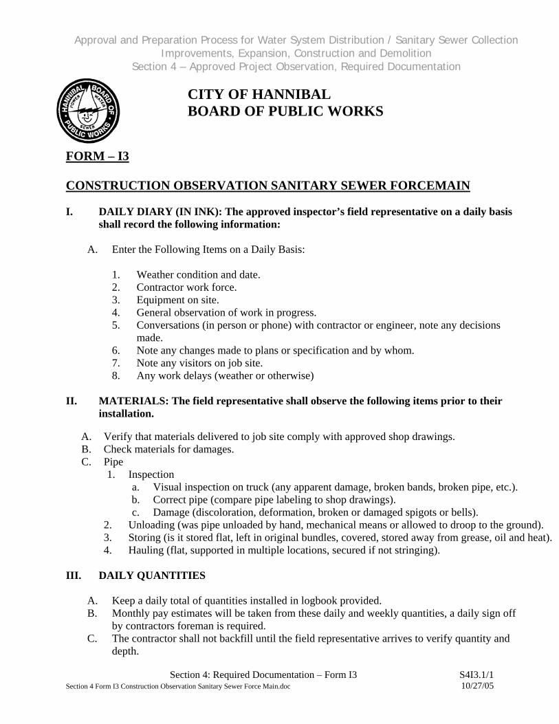
FORM – I3
CITY OF HANNIBAL BOARD OF PUBLIC WORKS
CONSTRUCTION OBSERVATION SANITARY SEWER FORCEMAIN
I. DAILY DIARY (IN INK): The approved inspector’s field representative on a daily basis
shall record the following information: A. Enter the Following Items on a Daily Basis: 1. Weather condition and date. 2. Contractor work force. 3. Equipment on site. 4. General observation of work in progress. 5. Conversations (in person or phone) with contractor or engineer, note any decisions made. 6. Note any changes made to plans or specification and by whom. 7. Note any visitors on job site. 8. Any work delays (weather or otherwise) II. MATERIALS: The field representative shall observe the following items prior to their
installation. A. Verify that materials delivered to job site comply with approved shop drawings. B. Check materials for damages. C. Pipe 1. Inspection a. Visual inspection on truck (any apparent damage, broken bands, broken pipe, etc.). b. Correct pipe (compare pipe labeling to shop drawings). c. Damage (discoloration, deformation, broken or damaged spigots or bells). 2. Unloading (was pipe unloaded by hand, mechanical means or allowed to droop to the ground). 3. Storing (is it stored flat, left in original bundles, covered, stored away from grease, oil and heat). 4. Hauling (flat, supported in multiple locations, secured if not stringing). III. DAILY QUANTITIES A. Keep a daily total of quantities installed in logbook provided. B. Monthly pay estimates will be taken from these daily and weekly quantities, a daily sign off by contractors foreman is required. C. The contractor shall not backfill until the field representative arrives to verify quantity and depth.

Approval and Preparation Process for Water System Distribution / Sanitary Sewer Collection Improvements, Expansion, Construction and Demolition
Section 4 – Approved Project Observation, Required Documentation
Section 4: Required Documentation – Form I3 S4I3.1/2 Section 4 Form I3 Construction Observation Sanitary Sewer Force Main.doc 10/27/05
IV. INSTALLATION A. Observe each pipe for damages, (broken bells, missing gaskets, cracks and/or gouges). B. Unstable Trench Walls (does excessive material fall back into the trench after excavation) C. Confirm Trench Depth (record on record drawings) D. Observe excavated material (is it free of rock) E. Pipe Placement 1. Spigot cleaned (for cut pipe – spigot bevel must be re-established) 2. Gasket checked 3. Gasket lubricated 4. Insertion mark within 1” of bell 5. Pipe lowered into trench (not dropped) F. As valves are being installed observe if they are per specification and that they have proper trust block and #3 rebar anchor is used (see details). G. As fittings (tee’s and 90°s) are being installed, observe if proper trust blocks are being used (See details). H. Note location of the new main on the record drawings I. Note location of all service lines and meters on the record drawings. J. Observe all testing of completed work (utilize Force Main Pressure Test Report form) V. CREEK CROSSING A. Field representative shall be on site at all times while creek crossing are being done. VI. HIGHWAY CROSSINGS A. Determine if proper permits are secured. B. Observe if steel casing being installed is size and type per plan. C. Observe if casing spacer for size and spacing intervals, double spacers on each end of pipe. D. Determine measure downs for each end for as builts. VII. SEWER SERVICE A. Observe if contractor installs valve correctly and at proper elevation. B. Valve should not be installed more than 5’ 0” passed property line. C. Meter locations shall be shown on plans. VIII. MISCELLANEOUS A. Keep ongoing list of work items requiring completion throughout the project. This will aid in preparing a punch list at the end of the project. B. Review contractor’s monthly pay request. C. Conduct a final project review with owner, engineer, contractor and funding agencies. D. Provide recording drawing to draftsmen so that the official “Record Drawings” can be produced.
Approval and Preparation Process for Water System Distribution / Sanitary Sewer Collection Improvements, Expansion, Construction and Demolition
SECTION 5
PERMITS AND AUTHORIZATION
FORMS
P1 APPLICATION FOR WATER MAIN CONSTRUCTION PERMIT
P2 CONSTRUCTION PERMIT FOR WATER LINE EXTENSIONS
P3 APPLICATION FOR LETTER OF AUTHORIZATION - WATER EXTENSION
P4 EXAMPLE LETTER OF AUTHORIZATION FOR SERVICE P5 MISSOURI DEPARTMENT OF NATURAL RESOURCES APPLICATION
FOR CONSTRUCTION PERMIT FOR SEWER EXTENSION P6 MISSOURI DEPARTMENT OF NATURAL RESOURCES
CONSTRUCTION PERMIT P7 APPLICATION FOR LETTER OF AUTHORIZATION – SEWER
EXTENSION

BOARD OF PUBLIC WORKSOFFICE 573-221-8050
FAX 573-221-7522 CITY OF HANNIBAL E-MAIL [email protected]
ELECTRIC, WATER AND SEWER DEPARTMENTS #3 INDUSTRIAL LOOP DRIVE • HANNIBAL, MISSOURI 63401
Approval and Preparation Process for Water System Distribution Sanitary Sewer Collection Improvements, Expansion, Construction and Demolition
Section 5 – Permits and Authorization Forms
Section 5: Permits and Authorization Forms – Form P1 S5P1.1/1 Section 5 Form P1 Application for Water Main Construction Permit.doc 10/27/05
Form P1 APPLICATION FOR WATER MAIN CONSTRUCTION PERMIT
Instructions:
Please type or print in ink. A completed and signed application form must accompany each set of plans and specifications that is submitted to the BPW for review and approval. No fee is required for a construction permit. Please direct inquiries to the above address or call (573) 221-8050.
I. Name of Project: ________________________________________________ ________________________________________________
II. Location: Township: Range: Section:
Quarter Section: County:
III. Scope of Project Number of feet of water line: __________________ Size of water line: __________________ Material used for water line extension: __________________ Number of new fire hydrants: __________________ IV. Contact Information Contractor: ______________________________ Phone Number: ____________ Engineer: ______________________________ Phone Number: ____________ Owner: ______________________________ Phone Number: ____________ I certify that the information entered in this application is true to the best of my knowledge and if granted a permit, the Hannibal Board of Public Works will in accordance with the final plans and specifications approve construction of this project. Print Name: Date: Sign Name:

BOARD OF PUBLIC WORKS OFFICE 573-221-8050
CITY OF HANNIBAL FAX 573-221-7522 E-MAIL [email protected]
ELECTRIC, WATER AND SEWER DEPARTMENTS #3 INDUSTRIAL LOOP DRIVE HANNIBAL, MISSOURI 63401
Approval and Preparation Process for Water System Distribution Sanitary Sewer Collection Improvements, Expansion, Construction and Demolition
Section 5 – Permits and Authorization Forms
Section 5: Permits and Authorization Forms – Form P2 S5P2.1/1 Section 5 Form P2 Construction Permit for Waterline Extensions.doc 10/27/05
Form P2
CONSTRUCTION PERMIT FOR WATER LINE EXTENSIONS
Introduction: Plans and Specifications for [name of project] _________________________were submitted for review and approval by [engineer] __________________________________. Brief Description: In general, these plans and specifications provide for a new waterline extension consisting of approximately [_________ Lineal feet of __________ Ductile Iron Pipe]. [_________ Lineal feet of __________ PVC Pipe]. The necessary valves, fittings, and appurtenances will be provided as per detailed plans and specifications. Before being placed in service, the waterline will be pressure tested, flushed, disinfected and sampled for bacteriological analyses.
Issued By:
Print Name: _________________ Date: Signature: Issued To:
Name: Address: APPROVAL TO CONSTRUCT The engineering plans and specifications described above were examined as to sanitary features of design which may affect the operation of the sanitary works, including size, capacities of the units, and factors which may be affect the efficiency and ease operation. Approval as regards these points is hereby given. Approval is given with the understanding that the Hannibal Board of Public Works shall make final inspection and approval of the completed works before it is accepted and placed in operation. There must be an approved inspector to oversee and sign off on the completion of the project. This construction permit is for a two (2) year period starting on the date written above. After the two-year period, this construction permit is null and void, and a new construction permit must be applied for. The Hannibal Board of Public reserves the right to withdraw the approval of plans and specifications at any time.

BOARD OF PUBLIC WORKSOFFICE 573-221-8050
FAX 573-221-7522 CITY OF HANNIBAL E-MAIL [email protected]
ELECTRIC, WATER AND SEWER DEPARTMENTS #3 INDUSTRIAL LOOP DRIVE • HANNIBAL, MISSOURI 63401
Approval and Preparation Process for Water System Distribution Sanitary Sewer Collection Improvements, Expansion, Construction and Demolition
Section 5 – Permits and Authorization Forms
Section 5: Permits and Authorization Forms – Form P3 S5P3.1/1 Section 5 Form P3 Application for Letter of Authorization Water Extension.doc 10/27/05
Form P3
APPLICATION FOR LETTER OF AUTHORIZATION FOR WATER EXTENSION
Instructions: Please type or print in ink. A completed and signed application form must be accompanied by a set of record drawings and appropriate test results, and submitted to the BPW for review and approval. No fee is required for a letter of authorization. Please direct inquiries to the above address or call (573) 221-8050. I. Name of Project: _______________________________________________________________________ II. Location: Township: Range: Section:
Quarter Section: County: III. Constructed Under Construction Permit No. IV. Contact Information Contractor: __________________________________________________ Address: __________________________________________________ __________________________________________________
Phone Number: _________________________
Engineer: __________________________________________________ Address: __________________________________________________ __________________________________________________ Phone Number: _________________________ Owner: __________________________________________________ Address: __________________________________________________ __________________________________________________
Phone Number: __________________________
Operating Authority: Hannibal Board of Public Works

BOARD OF PUBLIC WORKSOFFICE 573-221-8050
FAX 573-221-7522 CITY OF HANNIBAL E-MAIL [email protected]
ELECTRIC, WATER AND SEWER DEPARTMENTS #3 INDUSTRIAL LOOP DRIVE • HANNIBAL, MISSOURI 63401
Approval and Preparation Process for Water System Distribution Sanitary Sewer Collection Improvements, Expansion, Construction and Demolition
Section 5 – Permits and Authorization Forms
Section 5: Permits and Authorization Forms – Form P3 S5P3.1/2 Section 5 Form P3 Application for Letter of Authorization Water Extension.doc 10/27/05
V. Brief Description:
VI. Checklist: The following items must be turned into the Hannibal Board of Public Works with this Application for Letter of Authorization. Please check all items that are enclosed. All the following items must be signed and stamped by a Missouri licensed Professional Engineer.
Application for Letter of Authorization Record Drawings with copies of recorded easements if necessary Test Results
VII. Certification: I, the project engineer on the above described facilities, hereby certify that I have inspected
these facilities and find them to be constructed essentially in accordance with the approved plans and specifications, and recommend their acceptance and approval by the Hannibal Board of Public Works. The record drawings and specifications conform to the requirements contained in the Hannibal Board of Public Works’ current Water and Sewer Standards.
I certify that I am familiar with the information contained in this application, that to the best of my knowledge and belief, such information is true, complete, and accurate, and if granted this Letter of Authorization, I agree to abide by all applicable rules, regulations, orders and decisions. Print Name: Date: Sign Name:

BOARD OF PUBLIC WORKSOFFICE 573-221-8050
FAX 573-221-7522 CITY OF HANNIBAL E-MAIL [email protected]
ELECTRIC, WATER AND SEWER DEPARTMENTS #3 INDUSTRIAL LOOP DRIVE • HANNIBAL, MISSOURI 63401
Approval and Preparation Process for Water System Distribution Sanitary Sewer Collection Improvements, Expansion, Construction and Demolition
Section 5 – Permits and Authorization Forms
Section 5: Permits and Authorization Forms – Form P4 S5P4.1/1 Section 5 Form P4 BPW Letter Of Authorization For Water And Sewer Service Connection.doc 10/27/05
Form P4
LETTER OF AUTHORIZATION FOR SERVICE DATE NAME ADDRESS CITY, STATE ZIP RE: Letter of Authorization (WATER/SEWER) NAME OF PROJECT Dear MR. OR MS.; The Hannibal Board of Public Works has received all the necessary documentation in order to authorize service to the WATER/SEWER line. As of the date on this letter and in reference to the above-mentioned project, the WATER/SEWER line may be placed into service. Please schedule with the Hannibal Board of Public Works Water and Sewer Department at (573) 221-8050, 48 hours prior to placing the WATER/SEWER line into service. Sincerely, BOARD OF PUBLIC WORKS Heath N. Hall Water & Wastewater Facilities Engineer

Approval and Preparation Process for Water System Distribution Sanitary Sewer Collection Improvements, Expansion, Construction, Demolition
Section 5 – Permits and Authorization Forms Form P5
Approval and Preparation Process for Water System Distribution Sanitary Sewer Collection Improvements, Expansion, Construction, Demolition
Section 5 – Permits and Authorization Forms Form P5
Section 5: Permits and Authorization Forms – Form P5 S5P5.1/1 Section 5 Form P5 DNR Application for Construction Permit Sewer Extension.doc 10/27/05
Section 5: Permits and Authorization Forms – Form P5 S5P5.1/1 Section 5 Form P5 DNR Application for Construction Permit Sewer Extension.doc 10/27/05
Approval and Preparation Process for Water System Distribution Sanitary Sewer Collection Improvements, Expansion, Construction and Demolition
Section 5 – Permits and Authorization Forms Form P5.2
Section 5: Permits and Authorization Forms – Form P5.2 S5P5.2 Section 5 Form P5 DNR Application for Construction Permit Sewer Extension Instructions.doc 10/27/05
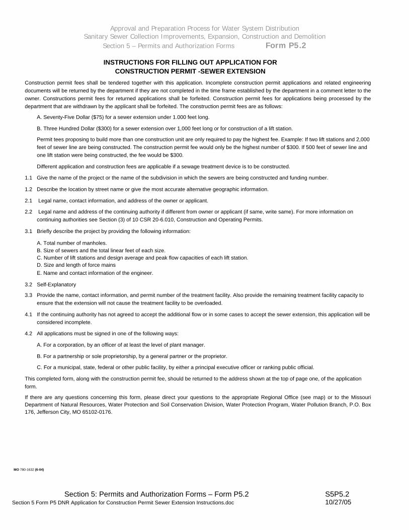
INSTRUCTIONS FOR FILLING OUT APPLICATION FOR CONSTRUCTION PERMIT -SEWER EXTENSION
Construction permit fees shall be tendered together with this application. Incomplete construction permit applications and related engineering documents will be returned by the department if they are not completed in the time frame established by the department in a comment letter to the owner. Constructions permit fees for returned applications shall be forfeited. Construction permit fees for applications being processed by the department that are withdrawn by the applicant shall be forfeited. The construction permit fees are as follows:
A. Seventy-Five Dollar ($75) for a sewer extension under 1.000 feet long.
B. Three Hundred Dollar ($300) for a sewer extension over 1,000 feet long or for construction of a lift station.
Permit tees proposing to build more than one construction unit are only required to pay the highest fee. Example: If two lift stations and 2,000 feet of sewer line are being constructed. The construction permit fee would only be the highest number of $300. If 500 feet of sewer line and one lift station were being constructed, the fee would be $300.
Different application and construction fees are applicable if a sewage treatment device is to be constructed.
1.1 Give the name of the project or the name of the subdivision in which the sewers are being constructed and funding number.
1.2 Describe the location by street name or give the most accurate alternative geographic information.
2.1 Legal name, contact information, and address of the owner or applicant.
2.2 Legal name and address of the continuing authority if different from owner or applicant (if same, write same). For more information on continuing authorities see Section (3) of 10 CSR 20-6.010, Construction and Operating Permits.
3.1 Briefly describe the project by providing the following information:
A. Total number of manholes. B. Size of sewers and the total linear feet of each size. C. Number of lift stations and design average and peak flow capacities of each lift station. D. Size and length of force mains E. Name and contact information of the engineer.
3.2 Self-Explanatory
3.3 Provide the name, contact information, and permit number of the treatment facility. Also provide the remaining treatment facility capacity to ensure that the extension will not cause the treatment facility to be overloaded.
4.1 If the continuing authority has not agreed to accept the additional flow or in some cases to accept the sewer extension, this application will be considered incomplete.
4.2 All applications must be signed in one of the following ways:
A. For a corporation, by an officer of at least the level of plant manager.
B. For a partnership or sole proprietorship, by a general partner or the proprietor.
C. For a municipal, state, federal or other public facility, by either a principal executive officer or ranking public official.
This completed form, along with the construction permit fee, should be returned to the address shown at the top of page one, of the application form.
If there are any questions concerning this form, please direct your questions to the appropriate Regional Office (see map) or to the Missouri Department of Natural Resources, Water Protection and Soil Conservation Division, Water Protection Program, Water Pollution Branch, P.O. Box 176, Jefferson City, MO 65102-0176.
MO 780-1632 (6-04)

Approval and Preparation Process for Water System Distribution Sanitary Sewer Collection Improvements, Expansion, Construction and Demolition
Section 5 – Permits and Authorization Forms Form P6.1
Section 5: Permits and Authorization Forms – Form P6.1 S5P6.1 Section 5 Form P6 MoDNR COnstruction Permit for Sewer Extension.doc 10/27/05
[EXAMPLE ONLY]
_____________________________________________________________ Director of Staff, Clean Water Commission or Designer
_____________________________________________________________ Stephen M. Mahfood, Director, Department of Natural Resources Executive Secretary, Clean Water Commission
July 12, 2001 Effective Date
July 12, 2002 Expiration Date $75 Fee Received
This permit applies only to the construction of water pollution control components; it does not apply to other environmentally regulated areas.
A representative of the department may inspect the work covered by this permit during construction. Issuance of a permit to Operate by the Department will be contingent on the work substantially adhering to the approved plans and specifications.
As the Department of Natural Resources does not examine structural features of design or the efficiency of mechanical equipment, the issuance of this permit does not include approval of these features.
________________________________________________________________________________________________________ Construction of such proposed facilities shall be in accordance with the provisions of the Missouri Clean Water Law, Chapter 644. RSMo. and regulation promulgated there under or this permit may be revoked by the Department of Natural Resources.
See Attached Permit Conditions
Permit Conditions:
See Attached Permit Description
for the construction of (described facilities):
CONSTRUCTION PERMIT The Missouri Department of Natural Resources hereby issues a permit to: Hannibal Board of Public Works 320 Broadway Hannibal, MO 63401
MISSOURI CLEAN WATER COMMISSION
DEPARTMENT OF NATURAL RESOURCES
STATE OF MISSOURI

Approval and Preparation Process for Water System Distribution Sanitary Sewer Collection Improvements, Expansion, Construction and Demolition
Section 5 – Permits and Authorization Forms Form P6.2
CONSTRUCTION PERMIT #25-2086 CERV Subdivision Sewer Extension
Hannibal, Missouri
Facility Description:
Construction of approximately 590 lineal feet of 8 inch PVC and 3 manholes and all of the necessary appurtenances to make this a complete and useable sewer. This gravity sewer extension is to serve the CERV subdivision. The location is in Hannibal, Missouri. These wastewater facilities will discharge to an existing city sewer treated at the Hannibal Wastewater Treatment Plant, Missouri State Operating Permit # MO-0093513.
Conditions:
Upon completion of construction the Hannibal Board of Public Works will become the continuing authority for operating and maintenance of these facilities.
Comments: It is recommended the Hannibal Board of Public Works assure on-site construction inspection is completed for this project.
[EXAMPLE ONLY]
Section 5: Permits and Authorization Forms – Form P6.2 S5P6.2 Section 5 Form P6 Page 2 MoDNR COnstruction Permit for Sewer Extension.doc 10/27/05
Approval and Preparation Process for Water System Distribution Sanitary Sewer Collection Improvements, Expansion, Construction and Demolition
Section 5 – Permits and Authorization Forms Form P6.3
Section 5: Permits and Authorization Forms – Form P6.3 S5P6.3 Section 5 Form P6 Page 3 MoDNR COnstruction Permit for Sewer Extension.doc 10/27/05
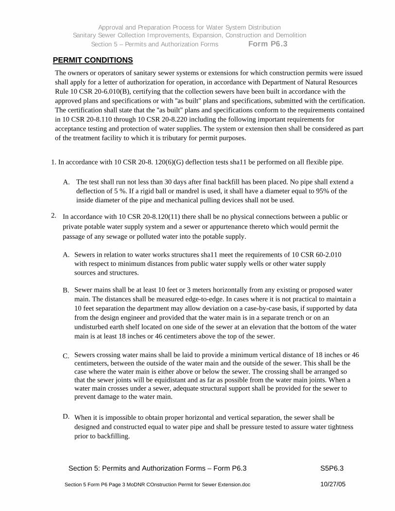
PERMIT CONDITIONS The owners or operators of sanitary sewer systems or extensions for which construction permits were issued shall apply for a letter of authorization for operation, in accordance with Department of Natural Resources Rule 10 CSR 20-6.010(B), certifying that the collection sewers have been built in accordance with the approved plans and specifications or with ''as built" plans and specifications, submitted with the certification. The certification shall state that the ''as built" plans and specifications conform to the requirements contained in 10 CSR 20-8.110 through 10 CSR 20-8.220 including the following important requirements for acceptance testing and protection of water supplies. The system or extension then shall be considered as part of the treatment facility to which it is tributary for permit purposes.
1. In accordance with 10 CSR 20-8. 120(6)(G) deflection tests sha11 be performed on all flexible pipe.
The test shall run not less than 30 days after final backfill has been placed. No pipe shall extend a deflection of 5 %. If a rigid ball or mandrel is used, it shall have a diameter equal to 95% of the inside diameter of the pipe and mechanical pulling devices shall not be used.
A.
2. In accordance with 10 CSR 20-8.120(11) there shall be no physical connections between a public or private potable water supply system and a sewer or appurtenance thereto which would permit the passage of any sewage or polluted water into the potable supply.
A. Sewers in relation to water works structures sha11 meet the requirements of 10 CSR 60-2.010 with respect to minimum distances from public water supply wells or other water supply sources and structures.
Sewer mains shall be at least 10 feet or 3 meters horizontally from any existing or proposed water main. The distances shall be measured edge-to-edge. In cases where it is not practical to maintain a 10 feet separation the department may allow deviation on a case-by-case basis, if supported by data from the design engineer and provided that the water main is in a separate trench or on an undisturbed earth shelf located on one side of the sewer at an elevation that the bottom of the water main is at least 18 inches or 46 centimeters above the top of the sewer.
B.
Sewers crossing water mains shall be laid to provide a minimum vertical distance of 18 inches or 46 centimeters, between the outside of the water main and the outside of the sewer. This shall be the case where the water main is either above or below the sewer. The crossing shall be arranged so that the sewer joints will be equidistant and as far as possible from the water main joints. When a water main crosses under a sewer, adequate structural support shall be provided for the sewer to prevent damage to the water main.
C.
D. When it is impossible to obtain proper horizontal and vertical separation, the sewer shall be designed and constructed equal to water pipe and shall be pressure tested to assure water tightness prior to backfilling.

Approval and Preparation Process for Water System Distribution
Sanitary Sewer Collection Improvements, Expansion, Construction and Demolition Section 5 – Permits and Authorization Forms Form P7
APPLICATION FOR LETTER OF AUTHORIZATION
(SEWER EXTENSION) DEPARTMENT OF NATURAL RESOURCES SUBMIT TO: Missouri Clean Water Commission P.O. Box 176 Jefferson City, MO 65102
DEPARTMENT OF NATURAL RESOURCES Northeast Regiona1 Office 1709 Prospect Drive Macon, MO 63552
1. Name of Project ________________________________________________
2. Location of Project ________________________________________________ 3. Constructed under Construction Permit No. ______________________________
4. Owner Name ____________________________ Phone _________________
Address ______________________________________________ ________________________________________________
5. Operating Name ____________________________ Phone _________________
Authority Address ______________________________________________ ________________________________________________
6. Brief Description ________________________________________________
________________________________________________
7. Certification: I, the project engineer on the above described facilities, hereby certify that I have inspected these facilities and find them to be constructed essentially in accordance with the approved plans and specifications, and recommend their acceptance and approval by the Missouri Clean Water Commission. The ''as built" plans and specifications conform to the requirements contained in 10 CSR 20-8.110 through 10 CSR 20-8.220 including the important requirements for acceptance testing and the protection of water supplies.
________________________________ __________________________ (Project Engineer's Signature) (Date)
I certify that I am fami1iar with the information contained in the app1ication, that to the best of my know1edge and belief, such information is true, comp1ete, and accurate, and if granted this Letter of Authorization, I agree to abide by a11 ru1es, regu1ations, orders and decisions of the Missouri C1ean Water Commission. ________________________________ __________________________ Applicant’s Signature (Owner or his (Date) legally authorized representative) NOTE: A filing fee is NOT required for a Letter of Authorization
Section 5: Permits and Authorization Forms – Form P7 S5P7 Section 5 Form P7 Application for Letter of Authorization for Sewer Extension.doc 10/27/05
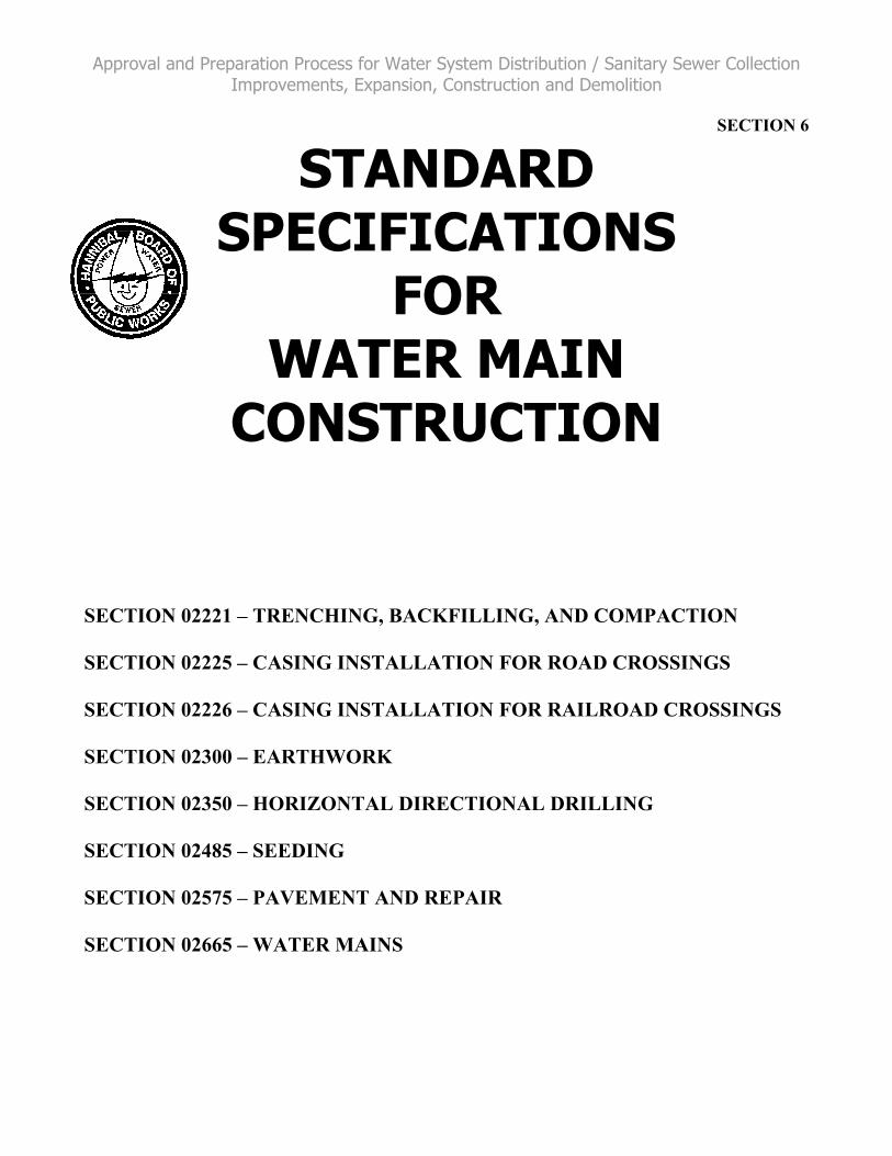
Approval and Preparation Process for Water System Distribution / Sanitary Sewer Collection Improvements, Expansion, Construction and Demolition
SECTION 6
STANDARD SPECIFICATIONS
FOR WATER MAIN
CONSTRUCTION
SECTION 02221 – TRENCHING, BACKFILLING, AND COMPACTION
SECTION 02225 – CASING INSTALLATION FOR ROAD CROSSINGS
SECTION 02226 – CASING INSTALLATION FOR RAILROAD CROSSINGS
SECTION 02300 – EARTHWORK
SECTION 02350 – HORIZONTAL DIRECTIONAL DRILLING
SECTION 02485 – SEEDING
SECTION 02575 – PAVEMENT AND REPAIR
SECTION 02665 – WATER MAINS

Hannibal 02221 – Page 1 of 3 August 2016
SECTION 02221
TRENCHING, BACKFILLING, AND COMPACTING
PART 1 ‐ GENERAL
1.1 RELATED WORK
Section 02665 ‐ Water Lines.
1.2 REFERENCE STANDARDS
ASTM D698 ‐ Moisture‐Density Relations of Soils and Soil Aggregate Mixtures, Using 5.5 lb. (2.5‐kg) Rammer and 12 in. (304.8‐mm) Drop.
City of Hannibal Board of Public Works Standard Water Main Installation Details (see Section 02665 for details).
PART 2 ‐ MATERIALS
2.1 PIPE EMBEDMENT MATERIAL
Granular bedding gradation shall be as follows:
Sieve Size Percent Passing
½” 100
3/8” 80‐100
#4 5‐80
#10 0‐5
1. Use for bedding of water line.
Do not use frozen material.
2.2 BACKFILL FOR UPPER PORTION OF TRENCH
Use material excavated from trench, free from stones or clods larger than 3 inches in dimension, debris, or frozen lumps for backfilling under unpaved areas.
Use granular materials as specified for backfilling under all roadways and driveways.
Granular Backfill material shall conform to ASTM C‐33, gradation size #57. At least 50 percent of the material greater than ½ inch sieve shall contain particles having three or more fractured faces. Material shall meet the following gradation:

Hannibal 02221 – Page 2 of 3 August 2016
Sieve Size Percent Passing
1” 95‐100
3/4” 90‐100
1/2” 25‐60
#4 0‐10
#8 0‐5
2.3 GEOTEXTILE FABRIC
Fabric for pipe bedding stabilization shall be woven polypropylene yards. Geotextile shall be wrapped around aggregate subgrade below pipe.
Mechanical Properties
1. Wide Width Tensile Strength (Ultimate) ASTM D4632 400 Lb./In.
2. Grab Tensile Elongation ASTM D4632 12%
3. Trapezoidal Tear Strength ASTM D4533 180 Lbs.
4. Mullen Burst Strength ASTM D3786 1200 psi
5. Puncture Strength ASTM D4833 160 Lbs
6. UV Resistance After 500 hrs ASTM D4355 70% strength
Hydraulic Properties
1. Apparent Opening Size ASTM D4751 30 US Sieve
2. Permittivity ASTM D4491 0.40/sec
PART 3 ‐ EXECUTION
3.1 PREPARATION AND LAYOUT
Establish location of all utilities. Provide coordination with utility companies.
3.2 CLEARING
Clear site as required. Do not disturb trees, shrubs, and other improvements which are to remain.
3.3 DRAINAGE
Provide for uninterrupted surface water flow during the work.
Provide drainage and/or pumps to maintain a dry trench during the course of the work.

Hannibal 02221 – Page 3 of 3 August 2016
3.4 EXCAVATION
Excavate in accordance with line and grade.
Any sheeting driven below the level of the top of pipe shall not be removed.
3.5 UNSUITABLE SUBGRADE
When material unsuitable as a firm base for the pipe or structure is encountered, the trench shall be over‐excavated a minimum of an additional 1‐foot depth and compacted pipe embedment material shall replace the over‐excavated material, enclosed in Geotextile Fabric, as approved by the Engineer or Owner.
3.6 BEDDING, HAUNCHING, AND BACKFILLING
Install pipe as shown on the City of Hannibal Board of Public Works Standard Water Main Installation Details attached in Section 2 of this Document.
Shape and compact bedding to provide uniform bearing of the pipe. Excavate bell holes to allow for unobstructed assembly of the joint. Make bell hole as small as practical. After the joint has been made, carefully fill bell hole with bedding material.
After pipe is jointed and aligned, install haunching material and compact. Ensure material is worked under the haunch of the pipe to provide adequate side support. Take precautions to prevent movement of the pipe during placement and compaction of haunching material.
Place and compact initial backfill to provide cover over the pipe. Protect pipe from large particles of backfill material.
In unpaved areas place balance of backfill by a method which will not damage or displace the pipe, nor cause bridging action in the trench. Continuously roll backfill material with excavating equipment so that excessive settlement of the trench material will not occur. Leave material neatly mounded over the trench. Maintain trench and fill settled areas as they occur. Finish grade to eliminate uneven areas.
3.7 TESTING AND COMPACTION
Refer to Section 02300‐Earthwork for compaction and testing requirements.
END OF SECTION 02221

Hannibal 02225 – Page 1 of 4 August 2016
SECTION 02225
CASING INSTALLATION FOR ROAD CROSSINGS
PART 1 ‐ GENERAL
1.1 RELATED DOCUMENTS
The installation of casing pipe shall conform to these Specifications and the Hannibal Board of Public Works, Marion County, and/or Ralls County Highway requirements.
Road cross shall be installed per the City of Hannibal Board of Public Works Typical Highway Crossing standard detail in Section 2 of this document.
1.2 SUBMITTALS
Submit details of proposed jacking or boring pits to the Owner showing locations, dimensions, and details of sheeting and shoring required, if requested.
1.3 RELATED WORK
Excavation backfilling and compaction for jacking and receiving pits and for open cut installation shall conform to the requirements set forth in these Specifications.
PART 2 ‐ PRODUCTS
2.1 MATERIAL
Casing pipe shall be bare wall steel pipe with a minimum yield strength of 35,000 psi and a minimum wall thickness as listed below:
Casing Outside Highway Crossing Diameter Casing Wall Thickness Inches Inches 8.625 0.250 10.75 0.250 12.75 0.250 14 0.250 16 0.250 18 0.250 20 0.312 24 0.312 30 0.375 36 0.500 42 0.500 48 0.625 54 0.625 60 0.625

Hannibal 02225 – Page 2 of 4 August 2016
66 0.625 72 0.750
Smooth wall steel plates with a nominal diameter of over 54 inches shall not be permitted.
The inside diameter of the casing pipe shall be at least four (4) inches greater than the outside diameter of the carrier pipe joints or couplings.
PART 3 ‐ EXECUTION
3.1 ALIGNMENT AND GRADE
Locate pipelines to cross roadways approximately right angles where practicable, but preferably at not less than 45 degrees. Do not place pipelines in culverts or under bridges where there is likelihood of their restricting the area required for the purposes for which the bridges or culverts were built, or of endangering the foundations. Install the casing pipe on an even grade for its entire length and sloped to one end or as noted in a profile plan if provided. Satisfy a maximum tolerance of 1.5% (18" in one hundred feet) with the desired location of the casing or as otherwise required by regulation or specified on the plans, whichever is more restrictive.
3.2 WELDING
Connect steel casing sections by fully welding around the entire circumference of the pipe. Welding shall conform to AWWA Standard C206.
3.3 PROTECTION AT ENDS OF CASING
Block up both ends of casings in such a way as to prevent the entrance of foreign material, but to allow leakage to pass in the event of a carrier break.
3.4 DEPTH OF INSTALLATION
Unless the depth of casing pipe is specifically specified on the drawings, the casing pipe depth shall be in accordance with City of Hannibal Board of Public Works standard details in Section 2 of this document.
3.5 CASING INSULATORS
The carrier pipe and casing shall be separated by an insulator. The insulator spacing shall be installed to support the weight of the pipe and contents. As a minimum, an insulator shall be placed a maximum of 2 feet from each side of a joint and evenly spaced along the carrier pipe at intervals not to exceed manufacturer’s specifications or 6 feet, whichever is less. Timber skids are not allowed. Double spacers shall be installed one foot from each end of the casing. Casing insulators shall be sized according to the manufactures specifications for pipe sizes from the following list of approved manufactures and casing types.
1. Advanced Products and Systems, Inc. (Model CI).
Hannibal 02225 – Page 3 of 4 August 2016
2. RACI (polyethylene model F‐60 for 12‐inch carrier pipe and smaller).
3. RACI shall not be used for carrier pipe larger than 12‐inch.
At the sole discretion of the Engineer, alternate manufacturers in lieu of those described above and new or improved products by the same manufactures may be permitted. To seek approval, adequately describe any proposed alternate product and submit the same with shop drawings and specifications to the Engineer. The Contractor cannot proceed to employ said alternate products prior to receiving written approval from the Engineer.
3.6 CASING PIPE END SEALS
Synthetic rubber end seals shall be installed on each end of the casing pipe.
Casing pipe end seals shall be Model AC Pull‐on End Seal as manufactured by Advanced Products and Systems, Inc. or Engineered approved equal.
3.7 INSTALLATION
Refer to the City of Hannibal Standard Typical Highway Crossing Detail in Section 2 of this document.
Install casing pipes by one of the following methods:
Jacking: This method shall be in accordance with the current American Railway Engineering Association Specifications, Chapter 1, Part 4, "Earth Boring and Jacking Culvert Pipe Through Fill", except that steel pipe shall be used with welded joints. Conduct this operation without hand mining ahead of the pipe and without the use of any type of boring, auguring or drilling equipment.
Design the bracing, backstops and jacks so that the jacking can progress without stoppage (except for adding lengths of pipe).
Drilling: This method employs the use of an oil field type rock roller bit, or a plate bit made up of individual roller cutter units, welded to the pipe casing being installed. Turn the pipe for its entire length from the drilling machine to the head to give the bit the necessary cutting action against the ground being drilled. Inject high density slurry (oil field drilling mud) through a supply line to the head to act as a cutter lubricant. Inject this slurry at the rear of the cutter units to prevent any jetting action ahead of the pipe. Advance the drilling machine on a set of steel rails (thus advancing the pipe) by a set of hydraulic jacks. The method can be used to drill earth or rock.
Boring: This method consists of pushing the pipe into the fill with a boring auger rotating within the pipe to remove the soil. When augers or similar devices are used for pipe placement, the front of the pipe shall be provided with mechanical arrangements or devices that will positively prevent the auger and cutting head from leading the pipe so that there will be no unsupported excavation ahead of the pipe. The auger and cutting head arrangement shall be removable from within the pipe in the event an obstruction is encountered. The over‐cut by the cutting head shall not exceed the outside diameter of the pipe by more than one‐half inch. The face of the cutting head shall be arranged to provide reasonable obstruction to the free flow of soft or poor material.

Hannibal 02225 – Page 4 of 4 August 2016
If an obstruction is encountered during installation that stops the forward action of the pipe, and if it becomes evident that it is impossible to advance the pipe, operations will cease and the pipe shall be abandoned in place and filled completely with grout.
Bored or jacked installations shall have a bore hole essentially the same as the outside diameter of the pipe. Grout any voids that develop. Also grout around the casing pipe when the bore hole diameter is greater than the outside diameter of the pipe by more than 1 inch.
END OF SECTION 02225

Hannibal 02226 – Page 1 of 6 August 2016
SECTION 02226
CASING INSTALLATION FOR RAILROAD CROSSINGS
PART 1 ‐ GENERAL
1.1 RELATED DOCUMENTS
The installation of casing pipe shall conform to these Specifications, the Hannibal Board of Public Works, and Railroad requirements.
1.2 SUBMITTALS
Provide Owner copies of insurance certificates required by Railroad.
Submit details of proposed jacking or boring pits to the Owner showing locations, dimensions, and details of sheeting and shoring required, if requested.
1.3 RELATED WORK
Excavation backfilling and compaction for jacking and receiving pits and for open cut installation shall conform to the requirements set forth in these Specifications.
1.4 QUALITY ASSURANCE
Conform to requirements of the railroad and as specified herein. Comply with the more stringent of these requirements, in the event of a conflict between documents.
1.5 JOB CONDITIONS
No separate payment will be made by Owner to the Contractor for reimbursement made to Norfolk Southern Railroad for any expenses incurred by Norfolk Southern Railroad for employment of flagman, inspectors, and other employees required to protect the right of way and property of railroads from damage arising out of and/or from the construction, maintenance, repair, renewal, modification, reconstruction, relocation, abandonment, or removal of the utility lines. The Contractor shall reimburse Norfolk Southern Railroad for such expenses within fifteen days after presentation of bill for such expenses is made by the Owner to the Contractor.
PART 2 ‐ PRODUCTS
2.1 CASING PIPE
Casing pipe shall be installed at crossings as shown on plans.
Casing pipe shall be bare wall steel pipe with a minimum yield strength of 35,000 psi.
Casing pipe shall have a minimum wall thickness as listed below:

Hannibal 02226 – Page 2 of 6 August 2016
Casing Nominal Diameter Casing Nominal Wall Thickness Inches Inches 10 and under 0.188 12 & 14 0.250 16 0.281 18 0.312 20 & 22 0.344 24 0.375 26 0.406 28 0.438 30 0.469 32 0.500 34 & 36 0.532 Smooth wall steel plates with a nominal diameter of over 72 inches shall not be permitted.
The inside diameter of the casing pipe shall be at least four (4) inches greater than the outside diameter of the carrier pipe joints or couplings.
PART 3 ‐ EXECUTION
3.1 GENERAL
Before any work is begun on the railroad crossing, the Contractor shall satisfy al requirements of the railroad, including all insurance requirements.
Any modification of an approved permit from the railroad is the sole responsibility of the Contractor, including:
1. All additional costs for application and preparation.
2. Any assistance required by the Owner to obtain a new permit shall be furnished and paid for by the Contractor.
3. The Contractor shall provide the railroad and/or the Owner with such insurance or bonds as it may require to cover damage and accidents on railroad property resulting from his operations.
4. The Contractor shall provide the railroad with such bonds or deposits as it may require to cover railroad charges.
5. The Contractor shall submit copies of all plans, procedures, etc., approved by the railroad, to the Owner prior to the start of construction on railroad property.
During construction, rail operations and facilities are not to be interfered with, interrupted, or endangered.
3.2 ALIGNMENT AND GRADE
Locate pipelines to cross roadways approximately right angles where practicable, but preferably at not less than 45 degrees. Do not place pipelines in culverts or under bridges
Hannibal 02226 – Page 3 of 6 August 2016
nor closer than 50 feet to any portion of any railroad bridge, building, or other important structure where there is likelihood of their restricting the area required for the purposes for which the bridges or culverts were built, or of endangering the foundations. Install the casing pipe on an even grade for its entire length and sloped to one end or as noted in a profile plan if provided. Satisfy a maximum tolerance of 1.5% (18" in one hundred feet) with the desired location of the casing or as otherwise required by regulation or specified on the plans, whichever is more restrictive.
Casing shall be installed so as to prevent the formation of a waterway under the railroad.
3.3 WELDING
Connect steel casing sections by fully welding around the entire circumerfence of the pipe. Welding shall conform to AWWA Standard C206.
3.4 PROTECTION AT ENDS OF CASING
Block up both ends of casings in such a way as to prevent the entrance of foreign material, but to allow leakage to pass in the event of a carrier break.
3.5 DEPTH OF INSTALLATION
Casing pipes placed under tracks shall be not less than 5 ½ feet from base of rail to top of pipe at its closest point. On other portion of the right‐of‐way, where the pipe is not directly beneath any track, the depth from ground surface will be 4 feet or from bottom of ditch to top of pipe shall not be less than 3 feet.
3.6 CASING INSULATORS
The carrier pipe and casing shall be separated by an insulator. The insulator spacing shall be installed to support the weight of the pipe and contents. As a minimum, an insulator shall be placed a maximum of 2 feet from each side of a joint and evenly spaced along the carrier pipe at intervals not to exceed manufacturer’s specifications or 6 feet, whichever is less. Timber skids are not allowed. Double spacers shall be installed one foot from each end of the casing. Casing insulators shall be sized according to the manufactures specifications for pipe sizes from the following list of approved manufactures and casing types.
1. Advanced Products and Systems, Inc. (Model CI).
2. RACI (polyethylene model F‐60 for 12‐inch carrier pipe and smaller).
3. RACI shall not be used for carrier pipe larger than 12‐inch.
At the sole discretion of the Engineer, alternate manufacturers in lieu of those described above and new or improved products by the same manufactures may be permitted. To seek approval, adequately describe any proposed alternate product and submit the same with shop drawings and specifications to the Engineer. The Contractor cannot proceed to employ said alternate products prior to receiving written approval from the Engineer.
3.7 CASING PIPE END SEALS
Hannibal 02226 – Page 4 of 6 August 2016
Synthetic rubber end seals shall be installed on each end of the casing pipe.
Casing pipe end seals shall be Model AC Pull‐on End Seal as manufactured by Advanced Products and Systems, Inc. or Engineered approved equal.
3.8 SIGNS
All pipelines shall be prominently marked at right‐of‐way lines (on both sides of track for crossings) by durable, weatherproof signs located over the centerline of the pipe. Signs shall conform to sample sign found attached as Exhibit A at the end of this specification section. Signs shall show the following:
1. Name and address of owner
2. Contents of pipe
3. Pressure in pipe
4. Pipe depth below grade at point of sign
5. Emergency telephone number in event of pipe rupture
3.9 INSTALLATION
Refer to the casing installation details and water main profile in the Contract Drawings for the water main railroad crossing details.
1. If an obstruction is encountered during installation that stops the forward action of the pipe, and if it becomes evident that it is impossible to advance the pipe, operations will cease and the pipe shall be abandoned in place and filled completely with grout and the City of Hannibal Board of Public Works contacted immediately.
2. Bored installations shall have a bore hole essentially the same as the outside diameter of the pipe. Grout any voids that develop. Also grout around the casing pipe when the bore hole diameter is greater than the outside diameter of the pipe by more than 1 inch.
3. The use of water or other liquids to facilitate casing emplacement and spoil removal is prohibited.
Install casing pipes through method described as follow:
1. Boring: This method consists of pushing the pipe into the fill with a boring auger rotating within the pipe to remove the soil. The boring operation shall be progressed on a 24‐hour basis without stoppage (except for adding lengths of pipe) until the leading edge of the pipe has reached the receiving pit. When augers or similar devices are used for pipe placement, the front of the pipe shall be provided with mechanical arrangements or devices that will positively prevent the auger and cutting head from leading the pipe so that there will be no unsupported excavation ahead of the pipe. The auger and cutting head arrangement shall be removable from within the pipe in the event an obstruction is encountered. The over‐cut by the cutting head shall not exceed the outside diameter of the pipe by more than one‐half inch. The face of the

Hannibal 02226 – Page 5 of 6 August 2016
cutting head shall be arranged to provide reasonable obstruction to the free flow of soft or poor material.
Grouting
1. A uniform mixture of 1:6 (cement:sand) cement grout shall be placed under pressure through the grout holes to fill any voids which exist between the pipe and undisturbed earth.
2. Grouting shall start at the lowest hole in each grout panel and proceed upwards simultaneously on both sides of the pipe.
3. A threaded plug shall be installed in each grout hole as the grouting is completed at that hole.
Soil Stabilization
1. Pressure grouting of the soils or freezing of the soils before jacking or boring may be required at the direction of railroad to stabilize soils, control water, prevent loss of material and prevent settlement or displacement of embankment. Grout shall be cement, chemical, or other special injection material selected to accomplish the necessary stabilization.
2. Materials to be used and the method of injection shall be prepared by a Registered Professional Soils Engineer or by experienced and qualified company specializing in this work as approved by railroad.
Dewatering
1. When water is known or expected to be encountered, pumps of sufficient capacity to handle the flow shall be maintained at the site as approved by railroad. Pumps in operation shall be constantly attended on a 24‐hour basis until, in the sole judgement of the railroad, the operation can be safely halted.
2. When dewatering, close observation shall be maintained to detect any settlement or displacement of railroad embankment, tracks, and facilities.
Safety Requirements
1. All operations shall be conducted so as not to interfere with, interrupt, or endanger the operation of trains nor damage, destroy, or endanger the integrity of railroad facilities. All work on or near railroad property shall be conducted in accordance with railroad safety rules and regulations. The Contractor shall secure and comply with the railroad’s safety rules and shall give written acknowledgement to railroad that they have been received, read, and understood by the Contractor and its employees. Operations will be subject to railroad inspection at any and all times.
2. All cranes, lifts, or other equipment that will be operated in the vicinity of the railroad’s electrification and power transmission facilities shall be electrically grounded as directed by railroad.
3. At all times when the work is being progressed, a field supervisor for the work with no less than twelve (12) months experience in the operation of the equipment being used shall be present. If boring equipment or similar machines are being used, the

Hannibal 02226 – Page 6 of 6 August 2016
machine operator also shall have no less than twelve (12) months experience in the operation of the equipment being used.
4. Whenever equipment or personnel are working closer than 15 feet from the centerline of an adjacent track, that track shall be considered as being obstructed. Insofar as possible, all operations shall be conducted no less than this distance. Operations closer than 15 feet from the centerline of a track shall be conducted only with the permission of, and as directed by, a duly qualified railroad employee present at the site of the work.
5. Crossing of tracks at grade by equipment and personnel is prohibited except by prior arrangement with, and as directed by railroad.
Blasting
1. Blasting will not be permitted
Protection of Drainage Facilities
1. If, in the course of construction, it may be necessary to block a ditch, pipe or other drainage facility, temporary pipes, ditches, or other drainage facilities shall be installed to maintain adequate drainage as approved by railroad. Upon completion of the work, the temporary facilities shall be removed and the permanent facilities restored.
2. Soil erosion methods shall be used to protect railroad ditches and other drainage facilities during construction on and adjacent to railroad right‐of‐way.
END OF SECTION 02226

Hannibal 02300 – Page 1 of 10 August 2016
SECTION 02300
EARTHWORK
PART 1 ‐ GENERAL
1.1 RELATED WORK
Section 02221 – Trenching, Backfill, and Compacting
1.2 SUMMARY
This Section includes the following:
1. Preparing of subgrade for building slabs, walks, and pavements.
2. Drainage fill course for support of building slabs is included as part of this work.
3. Aggregate base for walks and pavements is included as part of this work.
4. Excavating and backfilling for building foundations and electrical work.
5. Trenching and Excavating
6. Topsoil.
1.3 REFERENCES
Excavation consists of removal of material encountered to subgrade elevations indicated and subsequent disposal of materials removed.
Unauthorized excavation consists of removal of materials beyond indicated subgrade elevations or dimensions without specific direction of the Owner’s Representative. Unauthorized excavation, as well as remedial work directed by the Owner’s Representative, shall be at Contractor's expense.
1. Under footings and foundation bases, fill unauthorized excavation by extending indicated bottom elevation of footing or base to excavation bottom, without altering required top elevation. Lean concrete fill may be used to bring elevations to proper position when acceptable to the Owner’s Representative.
2. In locations other than those above, backfill and compact unauthorized excavations as specified for authorized excavations of same classification, unless otherwise directed by the Owner’s Representative.
Additional Excavation: When excavation has reached required subgrade elevations, notify the Owner's Representative, who will make an inspection of conditions. If the Owner's Representative determines that bearing materials at required subgrade elevations are unsuitable, continue excavation until suitable bearing materials are encountered and replace excavated material as directed by the Owner's Representative. Removal of unsuitable material and its replacement as directed will be paid on basis of Conditions of the Contract relative to changes in work.

Hannibal 02300 – Page 2 of 10 August 2016
Subgrade: The undisturbed earth or the compacted soil layer immediately below granular subbase, drainage fill, or topsoil materials.
Structure: Buildings, foundations, slabs, tanks, curbs, or other man‐made stationary features occurring above or below ground surface.
1.4 QUALITY ASSURANCE
Codes and Standards: Perform excavation work in compliance with applicable requirements of authorities having jurisdiction.
Testing and Inspection Service: The Contractor will engage a testing and inspection service approved by the Owner's Representative to perform soils testing and inspection during earthwork operations.
1.5 PROJECT CONDITIONS
Site Information: Record drawings and an above grade survey was used for the basis of the design. Conditions are not intended as representations or warranties of accuracy for subsurface conditions. The Owner's Representative will not be responsible for interpretations or conclusions drawn from this data by Contractor.
1. Test borings and other exploratory operations may be performed by Contractor, at the Contractor's option; however, no change in the Contract Sum will be authorized for such additional exploration.
Existing Utilities: Locate existing underground utilities in areas of excavation work. If utilities are indicated to remain in place, provide adequate means of support and protection during earthwork operations.
1. Should uncharted, or incorrectly charted, piping or other utilities be encountered during excavation, consult utility Owner's Representative immediately for directions. Cooperate with the Owner's Representative and utility companies in keeping respective services and facilities in operation. Repair damaged utilities to satisfaction of utility Owner's Representative.
2. Do not interrupt existing utilities serving facilities occupied by the Owner's Representative or others, except when permitted in writing by the Owner's Representative and then only after acceptable temporary utility services have been provided.
3. Provide minimum of 3 working days' notice to the Owner's Representative and Owner, and receive written notice to proceed before interrupting any utility.
4. Demolish and completely remove from site existing underground utilities indicated to be removed. Coordinate with utility companies for shutoff of services if lines are active.
Use of Explosives: Use of explosives is not permitted.
Hannibal 02300 – Page 3 of 10 August 2016
Protection of Persons and Property: Barricade open excavations occurring as part of this work and post with warning lights.
1. Protect existing structures, utilities, sidewalks, pavements and other facilities from damage caused by settlement, lateral movement, undermining, washout and other hazards created by earthwork operations.
PART 2 ‐ PRODUCTS
2.1 SOIL MATERIALS
General: Provide borrow soil materials when sufficient satisfactory soil materials are not available from excavations.
Satisfactory Soils: Soil Classification Groups GW, GP, SW, SP, CL and ML according to ASTM D 2487, or a combination of these groups; free of rock or gravel larger than 2 inches in any dimension, debris, waste, frozen materials, vegetation, and other deleterious matter.
1. Liquid Limit: 45 max.
2. Plasticity Index: 25 max.
Unsatisfactory Soils: Soil Classification Groups GM, GC, SM, SC, OL, CH, MH, OH, and PT according to ASTM D 2487, or a combination of these groups.
1. Unsatisfactory soils also include satisfactory soils not maintained within 2 percent of optimum moisture content at time of compaction.
Subbase Material: Naturally or artificially graded mixture of natural or crushed gravel, crushed stone, and natural or crushed sand; ASTM D 2940; with at least 90 percent passing a 1‐1/2‐inch sieve and not more than 12 percent passing a No. 200 sieve.
Base Course: Naturally or artificially graded mixture of natural or crushed gravel, crushed stone, and natural or crushed sand; ASTM D 2940; with at least 95 percent passing a 1‐1/2‐inch sieve and not more than 8 percent passing a No. 200 sieve.
Engineered Fill: Naturally or artificially graded mixture of natural or crushed gravel, crushed stone, and natural or crushed sand; ASTM D 2940; with at least 90 percent passing a 1‐1/2‐inch sieve and not more than 12 percent passing a No. 200 sieve.
Bedding Course: Naturally or artificially graded mixture of natural or crushed gravel, crushed stone, and natural or crushed sand; ASTM D 2940; except with 100 percent passing a 1‐inch sieve and not more than 8 percent passing a No. 200 sieve.
2.2 TOPSOIL
Topsoil shall be stockpiled for re‐use in landscape work. If quantity of stockpiled topsoil is insufficient, provide additional topsoil as required to complete landscape work.
If required, obtain additional topsoil from local sources or from areas having similar soil characteristics to that found at project site. Obtain topsoil only from naturally, well‐drained

Hannibal 02300 – Page 4 of 10 August 2016
sites where topsoil occurs in a depth of not less than 4 inches. Do not obtain from bogs or marshes.
PART 3 ‐ EXECUTION
3.1 EXCAVATION
Excavation is unclassified and includes excavation to subgrade elevations indicated, regardless of character of materials and obstructions encountered.
Excavation Classifications: The following classifications of excavation will be made when rock is encountered:
1. Earth Excavation includes excavation of pavements and other obstructions visible on surface; underground structures, utilities, and other items indicated to be demolished and removed; together with earth and other materials encountered that are not classified as rock or unauthorized excavation.
3.2 STABILITY OF EXCAVATIONS
Slope sides of excavations to comply with local codes, ordinances, and requirements of agencies having jurisdiction. Maintain sides and slopes of excavations in safe condition until completion of backfilling.
3.3 DEWATERING
Prevent surface water and subsurface or ground water from flowing into excavations and from flooding project site and surrounding area.
3.4 STORAGE OF EXCAVATED MATERIALS
Stockpile excavated materials acceptable for backfill and fill where directed. Place, grade, and shape stockpiles for proper drainage.
1. Locate and retain soil materials away from edge of excavations.
2. Dispose of excess excavated soil material and materials not acceptable for use as backfill or fill.
3.5 TOPSOIL EXCAVATION
Excavate topsoil from areas to be further excavated, re‐landscaped, or re‐graded.
Stockpile topsoil in area on‐site designated by the Owner's Representative. Remove excess topsoil not being reused. Excess subsoil, and the removal of same, shall become the responsibility of the Contractor. No additional payment will be made for removal of excess topsoil.
Stockpile topsoil to height not exceeding 8 feet. Cover to protect from erosion.

Hannibal 02300 – Page 5 of 10 August 2016
3.6 EXCAVATION FOR STRUCTURES
Conform to elevations and dimensions shown within a tolerance of plus or minus 0.10 foot, and extending a sufficient distance from footings and foundations to permit placing and removal of concrete formwork, installation of services, and other construction and for inspection.
1. Excavations for footings and foundations: Do not disturb bottom of excavation. Excavate by hand to final grade just before concrete reinforcement is placed. Trim bottoms to required lines and grades to leave solid base to receive other work.
3.7 TRENCH EXCAVATION FOR PIPES AND CONDUIT
Excavate trenches to uniform width, sufficiently wide to provide ample working room and a minimum of 6 to 9 inches of clearance on both sides of pipe or conduit.
Excavate trenches and conduit to depth indicated or required to establish indicated slope and invert elevations and to support bottom of pipe or conduit on undisturbed soil. Beyond building perimeter, excavate trenches to allow installation of top of pipe below frost line.
1. Where rock is encountered, carry excavation 6 inches below required elevation and backfill with a 6‐inch layer of crushed stone or gravel prior to installation of pipe.
3.8 COLD WEATHER PROTECTION
Protect excavation bottoms against freezing when atmospheric temperature is less than 35 degrees F.
3.9 SITE PREPARATION
In general, all cut areas and areas to receive fill and backfill shall be stripped of topsoil, soft soil, or other deleterious materials and fill to the depths indicated below. Topsoil shall be stockpiled for later use during landscaping. The exposed subgrade shall be proof rolled. Any soft soil areas shall be excavated and backfilled with fill compacted to the density specified in subsequent paragraphs.
3.10 BACKFILL AND FILL
General: Place soil material in layers to required subgrade elevations, for each area classification listed below, using materials specified in Part 2 of this Section.
1. Under grassed areas, use satisfactory excavated or borrow material.
2. Under walks and pavements, use subbase material, satisfactory excavated or borrow material, or a combination.
3. Under building slabs, use base course material.
4. Under piping and conduit and equipment, use subbase materials where required over rock bearing surface and for correction of unauthorized excavation. Shape excavation bottom to fit bottom 90 degrees of cylinder.

Hannibal 02300 – Page 6 of 10 August 2016
5. Backfill trenches with concrete where trench excavations pass within 18 inches of column or wall footings and that are carried below bottom of such footings or that pass under wall footings. Place concrete to level of bottom of adjacent footing.
Backfill excavations as promptly as work permits, but not until completion of the following:
1. Acceptance of construction below finish grade including, where applicable, dampproofing, waterproofing, and perimeter insulation.
2. Inspection, approval, and recording locations of underground utilities have been performed and recorded.
3. Removal of concrete formwork.
4. Removal of trash and debris from excavation.
5. Permanent or temporary horizontal bracing is in place on horizontally supported walls.
3.11 PLACEMENT AND COMPACTION
Ground Surface Preparation: Remove vegetation, debris, unsatisfactory soil materials, obstructions and deleterious materials from ground surface prior to placement of fills. Plow strip, or break up sloped surfaces steeper than 1 vertical to 4 horizontal so that fill material will bond with existing surface.
1. When existing ground surface has a density less than that specified under "Compaction" for particular area classification, break up ground surface, pulverize, moisture‐condition to optimum moisture content, and compact to required depth and percentage of maximum density.
Place backfill and fill materials in uniform layers not more than 8 inches in loose depth for material compacted by heavy compaction equipment, and not more than 4 inches in loose depth for material compacted by hand‐operated tampers.
Before compaction, moisten or aerate each layer as necessary to provide optimum moisture content. Compact each layer to required percentage of maximum dry density or relative dry density for each area classification. Do not place backfill or fill material on surfaces that are muddy, frozen, or contain frost or ice.
Place backfill and fill materials evenly adjacent to structures, piping, or conduit to required elevations. Prevent wedging action of backfill against structures or displacement of piping or conduit by carrying material uniformly around structure, piping, or conduit to approximately same elevation in each lift.
Fill and Backfill Placement: The fill shall be systematically compacted until densities given in the Compaction Summary are achieved. The soil shall be placed at a moisture content compatible with the required density. Depending on the soil moisture at the time of construction, aeration or wetting may be required to achieve proper compaction.

Hannibal 02300 – Page 7 of 10 August 2016
Deleterious material shall not be included in fill, and the fill shall not be placed on soft materials or frozen ground.
COMPACTION SUMMARY
Category Minimum Compaction*
Soil subgrade 88%
General soil fill 90%
Rock backfill 95%
* Measured as percent of the maximum dry density as determined by the Modified
Proctor test (ASTM D1557)
** Moisture content of +4/‐3% above/below optimum moisture content.
Trench Backfill: The soil or granular backfill shall not be jetted.
The trench backfill shall be mechanically compacted. The soil or granular material shall be placed and compacted in 6‐inch horizontal layers. The degree of compaction shall be similar to that required in the fill adjacent to the trench. In cut areas, or areas where no grade changes are required, the trench backfill shall be compacted to a minimum of 88 percent of the modified Proctor maximum dry density for soil and 92 percent for rock backfill.
Subgrade Protection: Proper drainage of the construction areas shall be provided to protect the foundation and floor slab subgrades from the detrimental effects of weather conditions during construction. Finished subgrades and foundation excavations shall be kept free of standing water at all times. Concrete shall be placed in foundations the same day they are excavated. Construction traffic on the prepared subgrades shall be kept to a minimum. Disturbed soil shall be reworked and repaired in accordance with the Owner's Representative’s requirements.
Water from the surface runoff, downspouts, and subsurface drains shall be collected and discharged by the Contractor through an appropriately designed site drainage system.
Control soil and fill compaction, providing minimum percentage of density specified for each area classification indicated below. Correct improperly compacted areas or lifts as directed by the Owner's Representative if soil density tests indicate inadequate compaction.
1. Percentage of Maximum Density Requirements: Compact soil to not less than the following percentages of maximum density, in accordance with ASTM D 1557:

Hannibal 02300 – Page 8 of 10 August 2016
a. Under structures, building slabs and pavements, compact top 12 inches of subgrade and each layer of backfill or fill material at 95 percent maximum density.
b. Under lawn or unpaved areas, compact top 6 inches of subgrade and each layer of backfill or fill material at 90 percent maximum density.
c. Under walkways, compact top 6 inches of subgrade and each layer of backfill or fill material at 95 percent maximum density.
2. Moisture Control: Where subgrade or layer of soil material must be moisture conditioned before compaction, uniformly apply water to surface of subgrade or layer of soil material. Apply water in minimum quantity as necessary to prevent free water from appearing on surface during or subsequent to compaction operations.
a. Remove and replace, or scarify and air dry, soil material that is too wet to permit compaction to specified density.
b. Stockpile or spread soil material that has been removed because it is too wet to permit compaction. Assist drying by discing, harrowing, or pulverizing until moisture content is reduced to a satisfactory value.
3.12 GRADING
General: Uniformly grade areas within limits of grading under this section, including adjacent transition areas. Smooth finished surface within specified tolerances, compact with uniform levels or slopes between points where elevations are indicated or between such points and existing grades.
Grading Outside Building Lines: Grade areas adjacent to building lines to drain away from structures and to prevent ponding. Finish surfaces free from irregular surface changes and as follows:
1. Lawn or Unpaved Areas: Finish areas to receive topsoil to within not more than 0.10 foot above or below required subgrade elevations.
2. Walks: Shape surface of areas under walks to line, grade, and cross‐section, with finish surface not more than 0.10 foot above or below required subgrade elevation.
3. Pavements: Shape surface of areas under pavement to line, grade, and cross‐section, with finish surface not more than 1 inch above or below required subgrade elevation.
Grading Surface of Fill under Building Slabs: Grade smooth and even, free of voids, compacted as specified, and to required elevation. Provide final grades within a tolerance of 1/2 inch when tested with a 10‐foot straightedge.
Compaction: After grading, compact subgrade surfaces to the depth and indicated percentage of maximum or relative density for each area classification.
3.13 PAVEMENT AND AGGREGATE BASE COURSE

Hannibal 02300 – Page 9 of 10 August 2016
General: Aggregate base course consists of placing material, in layers of specified thickness, over subgrade surface to support a pavement or walk.
Placing: Place aggregate base course material on prepared subgrade in layers of uniform thickness, conforming to indicated cross‐section and thickness. Maintain optimum moisture content for compacting material during placement operations.
1. When a compacted aggregate base course is indicated to be 6 inches thick or less, place material in a single layer. When indicated to be more than 6 inches thick, place material in equal layers, except no single layer more than 6 inches or less than 3 inches in thickness when compacted.
3.14 BUILDING SLAB DRAINAGE COURSE
General: Drainage course consists of placement of drainage fill material, in layers of indicated thickness, over subgrade surface to support concrete building slabs.
Placing: Place drainage fill material on prepared subgrade in layers of uniform thickness, conforming to indicated cross‐section and thickness. Maintain optimum moisture content for compacting material during placement operations.
1. When a compacted drainage course is indicated to be 6 inches thick or less, place material in a single layer. When indicated to be more than 6 inches thick, place material in equal layers, except no single layer more than 6 inches or less than 3 inches in thickness when compacted.
3.15 FIELD QUALITY CONTROL
Quality Control Testing During Construction: Allow testing service to inspect and approve each subgrade and fill layer before further backfill or construction work is performed.
1. Perform field density tests in accordance with ASTM D 1556 (sand cone method) or ASTM D 2167 (rubber balloon method), as applicable.
a. Field density tests may also be performed by the nuclear method in accordance with ASTM D 2922, providing that calibration curves are periodically checked and adjusted to correlate to tests performed using ASTM D 1556. In conjunction with each density calibration check, check the calibration curves furnished with the moisture gages in accordance with ASTM D 3017.
b. If field tests are performed using nuclear methods, make calibration checks of both density and moisture gages at beginning of work, on each different type of material encountered, and at intervals as directed by the Owner's Representative.
2. Pipe bedding: Perform at least one field in‐place density test per location for every 300 feet or less of trench.
3. Trench Backfill: Perform at least two field in‐place density tests per location (at the initial and final compacted backfill layers) for every 300 feet or less of trench.

Hannibal 02300 – Page 10 of 10 August 2016
4. Footing Subgrade: For each strata of soil on which footings will be placed, perform at least one test to verify required design bearing capacities. Subsequent verification and approval of each footing subgrade may be based on a visual comparison of each subgrade with related tested strata when acceptable to the Owner's Representative.
5. Paved Areas and Building Slab Subgrade: Perform at least one field density test of subgrade for every 2,000 sq. ft. of paved area or building slab, but in no case fewer than three tests. In each compacted fill layer, perform one field density test for every 2,000 sq. ft. of overlaying building slab or paved area, but in no case fewer than three tests.
6. Foundation Wall Backfill: Perform at least two field density tests at locations and elevations as directed.
a. If in opinion of the Owner's Representative, based on testing service reports and inspection, subgrade or fills that have been placed are below specified density, perform additional compaction and testing until specified density is obtained. No additional payment shall be made for this work. Retesting shall be performed at the contractor's expense.
3.16 EROSION CONTROL
Provide erosion control of areas adjacent to the proposed construction.
3.17 MAINTENANCE
Protection of Graded Areas: Protect newly graded areas from traffic and erosion. Keep free of trash and debris.
Repair and reestablish grades in settled, eroded and rutted areas to specified tolerances.
Settling: Where settling is measurable or observable at excavated areas during general project warranty period, remove surface (pavement, lawn, or other finish), add backfill material, compact, and replace surface treatment. Restore appearance, quality, and condition of surface or finish to match adjacent work, and eliminate evidence of restoration to greatest extent possible.
3.18 DISPOSAL OF EXCESS AND WASTE MATERIALS
Removal from the Owner's Property: Remove waste materials, including unacceptable excavated material, trash, and debris, and dispose of it off the Owner's property.
END OF SECTION 02300

Hannibal 02350 – Page 1 of 7 August 2016
SECTION 02350
HORIZONTAL DIRECTIONAL DRILLING
PART 1 ‐ GENERAL
1.1 WORK INCLUDED
This specification section includes the installation of water main by horizontal directional boring. The Contractor shall furnish all labor, materials, and equipment required to install the water main in accordance with this specification section.
The directional drill shall be accomplished by first drilling a pilot hole to design standards, and then enlarging the pilot hole no larger than 1.5 times larger than the outer diameter of the Certa‐Lok C900/RJ coupling or approved equal to accommodate the pull back of the pipe and a number to bore copper tracer wire through the enlarged hole.
1.2 REQUIREMENTS
Products delivered under this specification shall be manufactured only from water distribution pipe and couplings conforming to AWWA C900. The restrained joint pipe shall also meet all short term pressure test requirements AWWA C900. Pipe, couplings, and all locking splines components used thereon shall be completely non‐metallic to eliminate corrosion problems.
1.3 SUBMITTALS
Directional drilling contractor's qualifications and experience.
Work plan: Prior to beginning work, the Contractor must submit to the Engineer a work plan detailing the procedure and schedule to be used to execute the project. The work plan should include a description of all equipment to be used, down‐hole tools, a list of personnel and their qualification and experience. Work plan should be comprehensive, realistic and based on actual working conditions for this particular project. Plan should document the thoughtful planning required to successfully complete the project.
Material: Specifications on material to be used shall be submitted to Engineer. Material shall include the pipe, fittings and any other item which is to be an installed component of the project.
Equipment: Submit specifications on directional drilling equipment to be used to ensure that the equipment will be adequate to complete the project. Equipment shall include but not be limited to: drilling rig, mud system, down‐hole tools, guidance system and rig safety systems. Calibration records for guidance equipment shall be included. Specifications for any drilling fluid additives that Contractor intends to use or might use shall be submitted.

Hannibal 02350 – Page 2 of 7 August 2016
1.4 QUALITY ASSURANCE
All directional drilling operations shall be done by qualified directional drilling Contractor with at least 3 years’ experience involving work or a similar nature to the work required of this project.
Notify Engineer and Owner a minimum of two (2) days in advance of the start of work.
All work shall be performed in the presence of the Owner or Engineer.
PART 2 ‐ PRODUCTS
2.1 PVC PIPE
The pipe material to be used shall meet AWWA C900 standards for Polyvinyl Chloride pressure pipe and fittings with a dimension ratio DR 14, Class 300. The pipe shall be designated as Certa‐Lok C900/RJ as manufactured by Certain Teed Corporation or an approved equal.
The pipe shall be joined using a separate PVC coupling with beveled edges, built in sealing gaskets and restraining grooves. The restraining splines shall be square and made from Nylon 101.
Exposed splines shall be cut flush from coupling wait to reduce soil drag.
Couplings shall be beveled on leading edges to minimize soil friction.
Contractor shall adhere to the pipe manufacturer's most current calculations regarding tensile load limitations for trenchless application. This calculation shall be part of the required submittal.
Contractor shall adhere to the pipe manufacturers most current calculations regarding deflection and radius of curvature for Certa‐Lok C900/RJ pipe used for trenchless application. This calculation of each bore shall be part of the required submittal.
Pipe shall be furnished in nominal 20 feet lengths.
2.2 DIRECTIONAL DRILLING EQUIPMENT REQUIREMENTS
General: The directional drilling equipment shall consist of a directional drilling rig of sufficient capacity to perform the bore and pull back the pipe, a drilling fluid mixing, delivery and recovery system of sufficient capacity to successfully complete the installation, a drilling fluid recycling system to remove solids from the drilling fluid so that the fluid can be reused, a magnetic guidance system or walk over system to accurately guide boring operations, a vacuum truck of sufficient capacity to handle the drilling fluid volume, trained and competent personnel to operate the system. All equipment shall be in good, safe condition with sufficient supplies, materials and spare parts on hand to maintain the system in good working order for the duration of this project.

Hannibal 02350 – Page 3 of 7 August 2016
Drilling Rig: The directional drilling machine shall consist of a hydraulically powered system to rotate and push hollow drilling pipe into the ground at a variable angle while delivering a pressurized fluid mixture to guidable drill head. The machine shall be anchored to the ground to withstand the pulling, pushing and rotating pressure required to complete the installation. The hydraulic power system shall be self‐contained with sufficient pressure and volume to power drilling operations. Hydraulic system shall be free of leaks. Rig shall have a system to monitor and record maximum pull‐back pressure during pull‐back operations. There shall be a system to detect electrical current from the drill string and an audible alarm which automatically sounds when an electrical current is detected.
Drill Head: The drill head shall be steerable by changing its rotation and shall provide necessary cutting surfaces and drilling fluid jets.
Mud Motors (if required): Mud motors shall be of adequate power to turn the required drilling tools.
Drill Pipe: Shall be constructed of high quality 4130 seamless tubing, grade D or better, with threaded box and plans.
2.3 GUIDANCE SYSTEM
General: A Magnetic Guidance System (MGS) probe or proven gyroscopic probe and interface shall be used to provide a continuous and accurate determination of the location of the drill head during the drilling operation. The guidance shall be capable of tracking at all depths up to ten feet and in any soil condition. It shall enable the driller to guide the drill head by providing immediate information on the tool face, azimuth (horizontal direction) and inclination (vertical direction). The guidance system shall be accurate to +/- 2% of the vertical depth of the bore hole at sensing position at depths up to ten feet and accurate to 2-feet horizontally.
Components: The Contractor shall supply all components and materials to install, operate, and maintain the guidance system.
The guidance system shall be of a proven type and shall be set up and operated by personnel trained and experienced with the system. The operation shall be aware of any geo‐magnetic anomalies and shall consider such influences in the operation of the guidance system.
2.4 DRILLING FLUID (MUD) SYSTEM
Mixing System: A self‐contained, closed, drilling fluid mixing system shall be of sufficient size to mix and deliver drilling fluid composed of bentonite clay, potable water, and appropriate additives. Mixing system shall be able to molecularly shear, individual bentonite particles from the dry power to avoid clumping and ensure thorough mixing. Mixing system shall continually agitate the drilling fluid during drilling operations.
Drilling fluids: Drilling fluid shall be composed of clean water and bentonite clay. Water shall be from an authorized source with a pH of 8.5‐10. Water of a lower pH or
Hannibal 02350 – Page 4 of 7 August 2016
with excessive calcium shall be treated with the appropriate amount of sodium carbonate or equal. No additional material may be used in drilling fluid without prior approval from Engineer.
Delivery System: The mud pumping system shall have a minimum capacity of 35‐500 GPM and be capable of delivering the drilling fluid at a constant minimum pressure of 1200 psi. The delivery system shall have filters in‐line to prevent solids form being pumped into drill pipe. Connections between the pump and drill pipe shall be relatively leak‐free. Used drilling fluid and drilling fluid spilled during operations shall be contained and conveyed to the drilling fluid recycling system or shall be removed by vacuum trucks or other methods acceptable to Engineer. A berm, minimum of 12‐inches high, shall be maintained around drill rigs drilling fluid mixing system, entry and exit pits and drilling fluid recycling system to prevent spills into the surrounding environment. Pumps and/or vacuum truck(s) of sufficient size shall be in place to convey drilling fluid from containment areas to storage and recycling facilities for disposal.
2.5 OTHER EQUIPMENT
Pipe Rollers: Pipe rollers shall be used for pipe assembly during final product pull back.
2.6 PERSONNEL REQUIREMENTS
All personnel shall be fully trained in their respective duties as part of the directional drilling crew and in safety.
A competent and experienced supervisor representing the Contractor shall be present at all times during the actual drilling operations. A responsible representative who is thoroughly familiar with the equipment and type of work to be performed must be in direct charge and control of the operation at all times. In all cases, the supervisor must continually be present at the job site during the actual Directional Bore operation. The Contractor and Subcontractor shall have a sufficient number of competent workers on the job at all times to insure the Directional Bore is made in timely and satisfactory manner.
PART 3 ‐ EXECUTION
3.1 GENERAL REQUIREMENTS
The Engineer must be notified 2 days in advance of starting work. The Directional Bore shall not begin until the Engineer is present at the job site and agrees that proper preparation for the operation have been made. The Engineer's approval for beginning the installation shall in no way relieve the Contractor of the ultimate responsibility for the satisfactory completion of the work as authorized under the Contract.
All equipment used by the Contractor on Owner's property and right‐of‐ways may be inspected by the Owner or the Owner's Representatives and shall not be used if considered unsatisfactory by Owner or Owner's Representative.

Hannibal 02350 – Page 5 of 7 August 2016
The Contractor shall be fully responsible for all damages arising from his failure to comply with the regulations and the requirements of these Specifications.
3.2 DIRECTIONAL DRILLING OPERATION
The Contractor shall provide all material, equipment, and facilities required for directional drilling. Proper alignment and elevation of the bore hole shall be consistently maintained throughout the directional drilling operation.
The entire drill path shall be accurately surveyed with entry and exist stakes placed in the appropriate locations within the easements. If Contractor is using a magnetic guidance system, drill path will be surveyed for any surface geo‐magnetic variations or anomalies.
Contractor shall place silt fence between all drilling operations and any drainage, wetland, waterway or other area designed for such protection necessary by documents, state, federal and local regulations. Additional environmental protection necessary to contain any hydraulic or drilling fluid spills shall be put in place, including berms, liners, turbidity curtains and other measures. Contractor shall adhere to all applicable environmental regulations.
A complete list of drilling fluid additives and mixtures to be used in the directional operation will be submitted to the Engineer, along with their respective material Safety Sheets. All drilling fluids and loose cuttings shall be contained in pits or holding tanks for recycling or disposal, no fluids shall be allowed to enter any unapproved areas or natural waterways. Upon completion of the directional drill project, the drilling mud and cuttings shall be disposed of by the Contractor at an approved dump site.
Upon approval of the pilot hole location, the hole opening or enlarging phase of the installation shall begin. The bore hole diameter shall be increased to accommodate the pullback operation of the required size of PVC pipe. The type of hole opener or back reamer to be utilized in this phase shall be determined by the types of subsurface soil conditions that have been encountered during the pilot hole drilling operation. The reamer type shall be at the Contractor's discretion with the final hole opening being a maximum of 1.5 times larger than the outside diameter of the Certa‐Lok C900/Restrained Joint Coupling o r a p p r o v e d e q u a l to be installed in the bore hole.
The open bore hole may be stabilized by means of bentonite drilling slurry pumped through the inside diameter of the drill rod and through openings in the reamer. The drilling slurry must be in a homogenous/flowable state serving as an agent to carry the loose cuttings to the surface through the annulus of the borehole. The volume of bentonite mud required for each pullback shall be calculated based on soil conditions, diameter of the pipe couplings, capacity of the bentonite mud pump, and the speed

Hannibal 02350 – Page 6 of 7 August 2016
of pullback as recommended by the bentonite drilling fluid manufacture. The bentonite slurry is to be contained at the exit or entry side of the directional bore in pits or holding tanks. The slurry may be recycled at this time for reuse in the hole opening operation, or shall be hauled by the Contractor to an approved dumpsite for proper disposal.
The PVC pipe shall be joined together according to manufacturer's specifications. The gaskets and the ends of pipe must be inspected and cleaned with a wet cloth prior to each joint assembly so they are free of any dirt or sand. The ends of pipe must be free of any chips, scratches, or scrapes before pipe is assembled. A puling eye will be attached to the Certa‐Lok C900/RJ o r a p p r o v e d e q u a l pulling head on the lead stick of pipe which in turn will be attached to a swivel on the end of the drill pipe. This will allow for a straight, smooth pull of the product pipe as it enters and passes through the borehole toward the drill rig and original entrance hole of the directional bore. The product pipe will be elevated to the approximate angle of exit and supported by means of a side boom with roller arm, or similar equipment, to allow for the "free stress" situation as the pipe is pulled into the exit hole toward the drill rig. The product pullback phase of the directional operation shall be carried out in a continuous manner until the pipe reaches the original sentry side of the bore.
Copper wire as specified in Section 02665 for locating the PVC pipe shall be attached to the PVC pipe and pulled through the bore with the pipe.
3.3 PIPE HANDLING
Care shall be taken during transportation of the pipe such that it will not be cut, kinked or otherwise damaged.
Ropes, fabrics or rubber protected slings and straps shall be used when handling pipes.
Chains, cables or hooks inserted into the pipe ends shall not be used. Two slings spread apart shall be used for lifting each length of pipe. Pipe of fittings shall not be dropped into rocky or unprepared ground.
Pipes shall be stored on level ground, preferably turf or sand, free of sharp object which could damage the pipe. Stacking of the Certa‐Lok C900/RJ pipe shall be limited to a height that will not cause excessive deformation of the bottom layers of pipes under anticipated temperature conditions. Where necessary due to ground conditions, the pipe shall be stored on wooden sleepers, spaced suitably and of such width as not to allow deformation of the pipe at the point of contact with the sleeper or between supports.
The handling of the joint pipeline shall be in such a manner that the pipe is not damaged by dragging it over sharp and cutting objects. Slings for handling the pipeline shall not be positioned at pipe joints. Sections of the pipes with deep cuts and gouges shall be removed at the ends of the pipeline rejoined.

Hannibal 02350 – Page 7 of 7 August 2016
3.4 SITE RESTORATION
Following drilling operations, Contractor will demobilize equipment and restore the work site to the original conditions. All excavations will be backfilled and compacted according to the specifications.
Surface restoration shall be completed in accordance with the requirements of the contract.
END OF SECTION 02350

Hannibal 02485 – Page 1 of 2 August 2016
SECTION 02485
SEEDING
PART 1 ‐ GENERAL
1.1 DELIVERY, STORAGE, AND HANDLING
Deliver grass seed in original containers showing analysis of seed mixture, percentage of pure seed, year of production, net weight, date of packaging, and location of packaging. Damaged packages are not acceptable.
Deliver fertilizer in waterproof bags showing weight, chemical analysis, and name of manufacturer.
PART 2 ‐ PRODUCTS
2.1 FERTILIZER
Commercial type, 10‐10‐10 grade, granular type.
2.2 SEEDS
Meet the following minimum percentages for purity and germination, and maximum percentage for weed seed.
Type Purity Germination Weed Kentucky 31 Fescue 92 88 1.0 Perennial Rye 98 85 1.0 Red Fescue 97 85 1.0
2.3 MULCH
Non‐toxic to vegetation and to the germination of seed, free from noxious seeds and weed seeds, and fresh.
Wheat, rye, or oat straw, air dried.
2.4 APPLICATION RATES
Fertilizer: 10 pounds per 1,000 sq. ft.
Seeds:
1. Kentucky 31 Fescue: 1.25 lbs/l,000 sq. ft.
2. Perennial Rye: 0.50 lbs/1,000 sq. ft.

Hannibal 02485 – Page 2 of 2 August 2016
3. Redtop: Red Fescue: 0.25 lbs/1,000 sq. ft.
PART 3 ‐ EXECUTION
3.1 PREPARATION
When soil is in a tillable condition, cultivate to a depth of 4 inches, reducing soil particles to a size not larger than 2 inches.
Assure seed bed is level and free of weeds, clods, stones, root, sticks, rivulets, gullies, crusting, and caking.
3.2 FERTILIZING
Apply fertilizer and mix into the top 2 inches of soil. Apply within 48 hours of seeding.
3.3 SEEDING AND MULCHING
Uniformly sow seeds in two operations at right angles to each other. Within 12 hours after seeding roll areas at right angles to runoff with a lawn type roller. Do not over compact.
Within 24 hours of seeding apply mulch evenly and free of lump and knots.
3.4 MAINTENANCE PERIOD
Maintenance Period: Until final acceptance.
3.5 MAINTENANCE
Maintain surfaces and supply additional topsoil where necessary, including areas affected by erosion.
Replant damaged grass areas showing root growth failure, deterioration, bare or thin spots, and eroded areas.
3.6 ACCEPTANCE
Seeded areas will be accepted at end of maintenance period when seeded areas are properly established and otherwise acceptable.
3.7 SCOPE
Seed all areas disturbed by the construction operations of this project.
Seeding shall be done during the months of April, May, June, October, November or December.
END OF SECTION 02485

Hannibal 02575 – Page 1 of 2 August 2016
SECTION 02575
PAVEMENT AND REPAIR
PART 1 ‐ GENERAL
1.1 DESCRIPTION
Work includes patching and repair of all pavement disturbed by construction.
1.2 RELATED WORK
Section 02221 ‐ Trenching, Backfilling, and Compacting
1.3 REFERENCE STANDARDS
ASTM D698 ‐ Moisture‐Density Relations of Soils and Soil Aggregate Mixture, using 5.5 lb (2.5 kg) Rammer and 12 in. (304.8 mm) Drop.
Missouri State Highway and Transportation Commission: Missouri Standard Specifications for Highway Construction, including Section 613 Pavement Repair.
1.4 QUALITY ASSURANCE
All material and methods, except as specified otherwise below, shall meet the requirements of MSHTC Standards.
PART 2 ‐ PRODUCTS
2.1 AGGREGATE BASE COURSE MATERIALS
Aggregate: MoDOT Type 5 Mechanically Compacted, Missouri Standards of Highway Construction.
2.2 BITUMINOUS SURFACE COURSE AND PATCHING MATERIALS
Prime Coat: MC‐30, Missouri Standards of Highway Construction
Base Mix: MoDOT Base, Missouri Standards of Highway Construction
Tack Coat: SS‐1 or SS‐1H, Section 1015 Missouri Standards for Highway Construction.
Surface Mix: Type BP‐1 Current Missouri Standard Specifications for Highway Construction.
2.3 CONCRETE MATERIAL
Portland Cement: 4,000 psi at 28 days.

Hannibal 02575 – Page 2 of 2 August 2016
Normal‐weight Aggregates: ASTM C33, Class 4, and as follows. Provide aggregates from a single source.
1. Maximum Aggregate Size: 1 ½ inch.
Water: Potable
PART 3 ‐ EXECUTION
3.1 EXECUTION
All trenches in bituminous paved streets and bituminous driveways shall be repaired with Bituminous Patching Material to match the existing removed, but not less than 4” compacted in place.
All trenches in concrete sidewalk, driveways and streets shall be repaired/replace with concrete material to match the existing removed.
Pavement replaced shall adhere to the following procedures:
1. Place granular backfill to provide temporary surface over trenches in streets. Open street to traffic for one week. Repair all potholes and level surface daily, adding additional material as needed. Base under the pavement shall be 8 inches thick.
2. After pavement has been open to traffic for one week, saw cut and remove existing pavement 24 inches on both sides of trench, remove sufficient base course material, level, compact, and construct pavement patch per the City of Hannibal Board of Public Works standard “Typical Trench Details”, in Appendix A of this Document.
END OF SECTION 02575
Hannibal 02665 – Page 1 of 7 August 2016
SECTION 02665
WATER LINES
PART 1 ‐ GENERAL
1.1 SCOPE
The design and construction of water main construction shall be in conformance with Missouri Department of Natural Resources Minimum Design Standards for Missouri Community Water Systems. The work shall consist of furnishing all labor, materials, and equipment for the complete installation of water main extension and/or alterations, and appurtenances, in conformance with the lines and grades shown on the Plans or as established by the Engineer and as specified herein. Item of work or materials not specifically mentioned, but necessary for the completion of water main construction shall be considered as incidental to other items in the contract. The Contractor shall employ skilled workmen to install the main. The inspector may suspend the work until, in his opinion, skilled personnel are provided. In areas where contamination may permeate into the water system, non‐permeable materials for all portions of the water system shall be used including pipe, fittings, service connections, and hydrant leads. No water pipes shall be reused.
1.2 DESIGN
Water pressures in distribution systems below 20 psi are a violation of Missouri Safe Drinking Water Regulation 10 CSR 60‐4.080 (9), and MDNR considers pressures below 20 psi to be an imminent hazard to public health.
All water mains shall be sized in accordance with a hydraulic analysis based on flow demands and pressure requirements. Minimum pipe size for water mains shall be 6 inches.
Distribution systems shall be designed to maintain at least 35 psi normal working pressure at ground level at all points in the distribution system under all conditions of design flow not including fire flow.
Systems designed for fire protection shall provide a minimum flow of 250 GPM for a duration of two hours. Water mains that are not designed to provide fire protection shall not have fire hydrants connected to them.
1.3 REFERENCES
City of Hannibal Board of Public Works Standard Water Main Details found in Section 4 of this document.
AWWA C104 ‐ Cement‐Mortar Lining for Cast‐Iron and Ductile‐Iron Pipe and Fittings for Water.

Hannibal 02665 – Page 2 of 7 August 2016
AWWA C110 ‐ Gray‐Iron and Ductile‐Iron Fittings, 3 in. Through 48 in. for Water and Other Liquids.
AWWA C111 ‐ Rubber Gasket Joints for Cast‐Iron and Ductile‐Iron Pressure Pipe and Fittings.
AWWA C151 ‐ Ductile‐Iron Pipe Centrifugally Cast, in Metal Molds or Sand‐Lined Molds, for Water or Other Liquids.
AWWA C509 ‐ Resilient‐Seated Gate Valves, 3 through 12 NPS, for Water and Sewage Systems.
AWWA C600 ‐ Installation of Ductile‐Iron Water Mains and Their Appurtenances.
AWWA C651 ‐ Disinfecting Water Mains.
AWWA C115 ‐ Flanged Cast‐Iron and Ductile‐Iron Pipe with Threaded Flanges.
AWWA C900 – Polyvinyl Chloride (PVC) Pressure Pipe, 4‐inch Through 12‐inch for Water Distribution
ASTM D3139 – Joints for Plastic Pressure Pipe Using Flexible Elastomeric Seals.
ASTM F477 – Elastomeric Seals (Gaskets) for Joining Plastic Pipe
1.4 PRODUCT DELIVERY, STORAGE, AND HANDLING
Protect pipe from damage to coating and lining.
Immediately prior to lowering pipe or fittings into the trench, clean interior of dirt and foreign material, and swab with a solution of an effective bactericide.
Carefully examine each pipe and fitting for cracks and other defects while suspended above the trench immediately before installation.
1.5 JOB CONDITIONS
Whenever pipe laying is not actively in progress, open ends of all installed pipe and fittings shall be fitted with a watertight plug.
Separation of Water Mains and Sewers:
1. The new water main has been located so that the proper horizontal and vertical separation from the existing sewers has been provided where the water line parallels a sewer line. However, in the event field conditions reveal that a horizontal separation of 10 feet cannot be obtained, the water line shall be laid in a separate trench or on an undisturbed earth shelf located on one side of the sewer so that the bottom of the water main is at least 18 inches above the top of the sewer pipe.

Hannibal 02665 – Page 3 of 7 August 2016
2. Whenever the water main crosses a sewer main, a minimum vertical distance of 18 inches shall be provided between the outside of the water main and the outside of the sewer pipe. This distance shall be provided whether the water main is above or below the sewer pipe. At crossings, one full length of water pipe must be located so both joints will be as far from the sewer line as possible. Special structural support for the water and sewer lines shall be provided.
3. Water lines shall not pass through or come in contact with sewer manholes.
1.6 Utility Lines
Prior to excavation, Contractor shall locate all existing utilities, and install water main to avoid conflicts. There will be no additional compensation for alignment or depth adjustments to avoid additional utilities.
PART 2 ‐ PRODUCTS
2.1 PIPE AND FITTINGS
Ductile Iron Pipe:
1. AWWA C151, Thickness Class 52 push‐on and mechanical joint pipe outside the railroad right‐of‐way, Thickness Class 56 for mechanical joint within the railroad right‐of‐way; AWWA C115 Thickness Class 53 for flanged.
2. Fittings: Ductile Iron, AWWA C110 or AWWA C153, Pressure rating 350 psi for mechanical joint and pressure rating 250 psi for flanged joint.
3. Joints: AWWA C111, and AWWA C115, Mechanical joint with ductile iron glands; push‐on joint with neoprene gaskets; 125# flanged joints (ASTM B16.1) w/full face hypalon gaskets
4. Restrained Joints: Restrained ductile iron pipe mechanical joints shall be EBBA Iron Megalug Series 1100 or approved equal.
a. Restrained joints will be required at all fittings, including bends, tees, crosses, fire hydrants, caps and plugs, and all pipes labeled to be restrained.
5. Lining: Cement mortar, AWWA C104, for all pipe and fittings.
PVC Pipe:
1. AWWA C900, Pressure Class 305 psi (DR 14)
2. Joints: ASTM D3139 with ASTM F477 Gaskets
3. Fittings: Ductile Iron, AWWA C110, Pressure rating 350 psi for mechanical joint and pressure rating 250 psi for flanged joint.
4. Restrained joints: Required at all fittings, including bends, tees, crosses, fire hydrants, caps and plugs, and all pipes labeled to be restrained.
a. Restrained Joints at Fitttings: EBBA Iron Megalug Series 2000PV or Approved Equal.

Hannibal 02665 – Page 4 of 7 August 2016
b. Restrained Joints at Pipe to Pipe Connections: EBBA Iron Series 1900, Eagle Loc 900 as manufactured by JM Eagle, CertaLok restrained joint, or Approved Equal.
2.2 GATE VALVES AND BOX
Gate valves shall be iron body, bronze trim, resilient seated, non‐rising stem, turning clockwise to open. Valves shall meet the requirements of AWWA C509. Valve shall be furnished with standard operating nut. Valve shall operate smoothly through the entire lift. Two valve wrenches shall be supplied.
Valve boxes shall be standard design cast‐iron with cover. Boxes shall have an outside diameter of not less than 4 inches with a minimum thickness of metal at any point of not less than 0.1875 inches.
See the City of Hannibal Board of Public Works standard details in Appendix A of this Document for manufacturers.
2.3 TAPPING VALVE
Tapping valve shall meet requirements of Section 2.2‐Gate Valves and Box except that it shall be equipped with a raised lip construction in accordance with MSS‐SP 60 to provide for centering of valve on tapping saddle.
Valve shall be manufactured by Mueller, Kennedy, or Engineer Approved Equal and supplied by the Owner.
2.4 TAPPING SLEEVE
Tapping sleeve shall be stainless steel. The seal shall be fully circumferentially shaped and approved for potable water. Outlet flange dimensions and drilling shall comply with ANSI B16.1, Class 125, and with MSS SP‐60.
Tapping sleeve shall be manufactured by Mueller Company, American Flow Control, or Engineer Approved Equal and supplied by the owner.
2.5 FIRE HYDRANTS
Fire hydrants shall be a Mueller 5 ¼” Super Centurion Hydrant as detailed in the City of Hannibal Board of Public Works standard details found in Appendix A of this Document.
Hydrants shall be a 3 way with one 4 ½” pumper nozzle and two 2 ½” hose connections. The inlet connection shall be 6” with mechanical joint.
2.6 THRUST BLOCKS
A. Concrete for thrust blocks shall be 3,000 psi minimum.
2.7 LOCATOR WIRE
Hannibal 02665 – Page 5 of 7 August 2016
A. The water main locator wire shall be blue HDPE insulated single strand #12 AWG continuous copper clad steel tracer wire with minimum 380 lb break load, with minimum 30 mil insulation thickness. All splices shall be per the wire manufacturer’s recommendations.
B. Tracer wire shall be manufactured by Copperhead Industries, LLC or Engineer Approved Equal.
2.8 WARNING TAPE
A. Blue warning tape shall be non‐metallic with a width of 3 inches and a minimum thickness of 5 mils.
B. Warning tape shall have “Caution Buried Water Line” or similar warning message printed on the tape at a minimum of 2 feet intervals.
PART 3 ‐ EXECUTION
3.1 PREPARATION
Establish line and grade for pipe and appurtenances.
Examine trench foundation for stability. Do not install material until defects have been corrected.
3.2 INSTALLATION
Install the water main per the City of Hannibal Board of Public Works standard details in Section 4 of this Document.
Install pipe in trench prepared as specified in Section 02221.
During pipe installation Contractor shall take every precaution to prevent foreign material from entering the pipe before, during, and after installation. This includes but is not limited to dirt, rock, animals, groundwater, surface water, rags, etc. If the pipe laying crew cannot install the pipe or fittings without getting foreign material in it, the Contractor shall place a heavy tightly woven canvas bag over each end before lowering it into the trench.
Make pipe joints is accordance with manufacturer’s instructions.
Pipe shall be laid with the bells pointing in the direction of laying.
Field cutting of pipe shall be done according to the manufacturer’s recommendations. Cut end shall be smooth and at right angles to the axis of the pipe. Field cuts shall be filed or trimmed to resemble the spigot end of the pipe as manufactured. Depth marks shall be placed on the pipe to assure pipe is inserted to the full depth when joint is made.
Thrust blocking and restrained joints shall be provided at all bends of 11‐1/4o or greater and tees and valves. Blocking shall be poured against undisturbed earth, be a minimum of 12 inches thick, and constructed so that the pipe and fitting joints will be accessible for repairs. Thrust block dimensions shall be in accordance with the City of Hannibal Board of Public Works standard details found in Appendix A of this Document.

Hannibal 02665 – Page 6 of 7 August 2016
Valve boxes shall be set accurately to the grade of the street or finished ground surface.
PVC pipe shall have continuous tracer wire installed with and attached to the top of the water main and secured (tied/taped) at 5 feet on centers. Ductile iron pipe shall have continuous tracer wire installed 6 inches above the pipe.
1. Install in accordance with the manufacturer’s installation instructions.
2. The tracer wire shall be looped to the surface at all valve boxes and fence crossings.
3. All tracer wire installations shall be located using typical low frequency (512 Hz) line tracing equipment, witnessed by the Contractor, Engineer, and Owner prior to acceptance of the project.
All PVC water main shall have a continuous blue warning tape installed 2 feet above the water main.
The Owner will supply all tapping sleeves and valves for hot taps to the contractor, and the Owner will perform all hot taps for the Contractor. Contactor is responsible for coordinating all needed hot taps with Owner.
Abandonment of the 6‐inch water main shall consist of the following:
1. Remove the 12” x 6” tapping sleeve and valve and place a full circle clamp around the 12‐inch main. Plug end of abandoned 6‐inch main with concrete.
2. Valve box abandonment:
a. Valve boxes in soil shall be removed, filled with clean soil and compacted to prevent settlement.
b. Valve box in concrete pavement shall be removed, filled with clean granular backfill, 3 foot square section of concrete pavement removed (saw‐cut) and replaced with new concrete pavement equal to or better than existing pavement, doweled to existing pavement.
3.3 FIELD TESTS
All newly laid water lines shall be tested before being placed in service. Trenches may be backfilled as the pipe is laid, or where practicable and at the option of the Contractor, trenches or bell holes may be left open for visual inspection during tests. Prior to making tests, all air shall be expelled from the pipe. Contractor shall install taps at high points of the line for purpose of expelling air.
Prior to testing, Contractor shall submit testing plan to Owner and Engineer for review and approval. Testing lengths shall be limited to a maximum of 1,000 feet unless otherwise approved by Owner.
Pressure Test: Water line pressure testing shall be in accordance with paragraph 6.31 of Section 1 of this document.

Hannibal 02665 – Page 7 of 7 August 2016
3.4 DISINFECTING WATER LINES
All testing, filling, flushing, and disinfections of new water main are to be conducted under direct supervision of the Hannibal Board of Public Works per paragraph 6.32 in Section 1 of this document.
Sterilizing of the completed lines shall be done in accordance with AWWA C651 and in a manner approved by the Missouri Department of Natural Resources.
Prior to chlorination, the main shall be flushed as thoroughly as possible with the water pressure and outlets available. Flushing shall be done after the pressure tests are made. After flushing, all valves shall be carefully inspected to see that the entire operating mechanism is in good condition.
Following sterilization, all treated water shall be thoroughly flushed from the newly laid pipeline at its extremities until the replacement water throughout its length shall, upon test, be proved comparable to the quality of water served the public from the existing water supply system and approved by the Owner. This quality of water delivered by the new main should continue for a period of at least two full days as demonstrated by laboratory examination of samples taken from a tap located and installed in such a way as to prevent outside contamination. Samples shall not be taken from an unsterilized hose or from a fire hydrant. The Hannibal Board of Public Works will run the test for the Contractor at the City’s Water Treatment Plant.
Should the initial treatment fail to result in the condition specified in the preceding paragraph, the sterilizing procedure shall be repeated until such results are obtained. The Contractor is responsible and shall obtain the approval of the Owner for the work performed under this contract.
END OF SECTION 02665

Approval and Preparation Process for Water System Distribution / Sanitary Sewer Collection Improvements, Expansion, Construction and Demolition
SECTION 7
STANDARD SPECIFICATIONS
FOR SANITARY SEWER MAIN
CONSTRUCTION
SECTION 02221 – TRENCHING, BACKFILLING, AND COMPACTION
SECTION 02225 – CASING INSTALLATION FOR ROAD CROSSINGS
SECTION 02226 – CASING INSTALLATION FOR RAILROAD CROSSINGS
SECTION 02300 – EARTHWORK
SECTION 02485 – SEEDING
SECTION 02575 – PAVEMENT AND REPAIR
SECTION 02710 – SEWER LINES
SECTION 02720 – MANHOLES

Hannibal 02221 – Page 1 of 3 August 2016
SECTION 02221
TRENCHING, BACKFILLING, AND COMPACTING
PART 1 ‐ GENERAL
1.1 RELATED WORK
Section 02665 ‐ Water Lines.
1.2 REFERENCE STANDARDS
ASTM D698 ‐ Moisture‐Density Relations of Soils and Soil Aggregate Mixtures, Using 5.5 lb. (2.5‐kg) Rammer and 12 in. (304.8‐mm) Drop.
City of Hannibal Board of Public Works Standard Water Main Installation Details (see Section 02665 for details).
PART 2 ‐ MATERIALS
2.1 PIPE EMBEDMENT MATERIAL
Granular bedding gradation shall be as follows:
Sieve Size Percent Passing
½” 100
3/8” 80‐100
#4 5‐80
#10 0‐5
1. Use for bedding of water line.
Do not use frozen material.
2.2 BACKFILL FOR UPPER PORTION OF TRENCH
Use material excavated from trench, free from stones or clods larger than 3 inches in dimension, debris, or frozen lumps for backfilling under unpaved areas.
Use granular materials as specified for backfilling under all roadways and driveways.
Granular Backfill material shall conform to ASTM C‐33, gradation size #57. At least 50 percent of the material greater than ½ inch sieve shall contain particles having three or more fractured faces. Material shall meet the following gradation:

Hannibal 02221 – Page 2 of 3 August 2016
Sieve Size Percent Passing
1” 95‐100
3/4” 90‐100
1/2” 25‐60
#4 0‐10
#8 0‐5
2.3 GEOTEXTILE FABRIC
Fabric for pipe bedding stabilization shall be woven polypropylene yards. Geotextile shall be wrapped around aggregate subgrade below pipe.
Mechanical Properties
1. Wide Width Tensile Strength (Ultimate) ASTM D4632 400 Lb./In.
2. Grab Tensile Elongation ASTM D4632 12%
3. Trapezoidal Tear Strength ASTM D4533 180 Lbs.
4. Mullen Burst Strength ASTM D3786 1200 psi
5. Puncture Strength ASTM D4833 160 Lbs
6. UV Resistance After 500 hrs ASTM D4355 70% strength
Hydraulic Properties
1. Apparent Opening Size ASTM D4751 30 US Sieve
2. Permittivity ASTM D4491 0.40/sec
PART 3 ‐ EXECUTION
3.1 PREPARATION AND LAYOUT
Establish location of all utilities. Provide coordination with utility companies.
3.2 CLEARING
Clear site as required. Do not disturb trees, shrubs, and other improvements which are to remain.
3.3 DRAINAGE
Provide for uninterrupted surface water flow during the work.
Provide drainage and/or pumps to maintain a dry trench during the course of the work.
Hannibal 02221 – Page 3 of 3 August 2016
3.4 EXCAVATION
Excavate in accordance with line and grade.
Any sheeting driven below the level of the top of pipe shall not be removed.
3.5 UNSUITABLE SUBGRADE
When material unsuitable as a firm base for the pipe or structure is encountered, the trench shall be over‐excavated a minimum of an additional 1‐foot depth and compacted pipe embedment material shall replace the over‐excavated material, enclosed in Geotextile Fabric, as approved by the Engineer or Owner.
3.6 BEDDING, HAUNCHING, AND BACKFILLING
Install pipe as shown on the City of Hannibal Board of Public Works Standard Water Main Installation Details attached in Section 2 of this Document.
Shape and compact bedding to provide uniform bearing of the pipe. Excavate bell holes to allow for unobstructed assembly of the joint. Make bell hole as small as practical. After the joint has been made, carefully fill bell hole with bedding material.
After pipe is jointed and aligned, install haunching material and compact. Ensure material is worked under the haunch of the pipe to provide adequate side support. Take precautions to prevent movement of the pipe during placement and compaction of haunching material.
Place and compact initial backfill to provide cover over the pipe. Protect pipe from large particles of backfill material.
In unpaved areas place balance of backfill by a method which will not damage or displace the pipe, nor cause bridging action in the trench. Continuously roll backfill material with excavating equipment so that excessive settlement of the trench material will not occur. Leave material neatly mounded over the trench. Maintain trench and fill settled areas as they occur. Finish grade to eliminate uneven areas.
3.7 TESTING AND COMPACTION
Refer to Section 02300‐Earthwork for compaction and testing requirements.
END OF SECTION 02221

Hannibal 02225 – Page 1 of 4 August 2016
SECTION 02225
CASING INSTALLATION FOR ROAD CROSSINGS
PART 1 ‐ GENERAL
1.1 RELATED DOCUMENTS
The installation of casing pipe shall conform to these Specifications and the Hannibal Board of Public Works, Marion County, and/or Ralls County Highway requirements.
Road cross shall be installed per the City of Hannibal Board of Public Works Typical Highway Crossing standard detail in Section 2 of this document.
1.2 SUBMITTALS
Submit details of proposed jacking or boring pits to the Owner showing locations, dimensions, and details of sheeting and shoring required, if requested.
1.3 RELATED WORK
Excavation backfilling and compaction for jacking and receiving pits and for open cut installation shall conform to the requirements set forth in these Specifications.
PART 2 ‐ PRODUCTS
2.1 MATERIAL
Casing pipe shall be bare wall steel pipe with a minimum yield strength of 35,000 psi and a minimum wall thickness as listed below:
Casing Outside Highway Crossing Diameter Casing Wall Thickness Inches Inches 8.625 0.250 10.75 0.250 12.75 0.250 14 0.250 16 0.250 18 0.250 20 0.312 24 0.312 30 0.375 36 0.500 42 0.500 48 0.625 54 0.625 60 0.625

Hannibal 02225 – Page 2 of 4 August 2016
66 0.625 72 0.750
Smooth wall steel plates with a nominal diameter of over 54 inches shall not be permitted.
The inside diameter of the casing pipe shall be at least four (4) inches greater than the outside diameter of the carrier pipe joints or couplings.
PART 3 ‐ EXECUTION
3.1 ALIGNMENT AND GRADE
Locate pipelines to cross roadways approximately right angles where practicable, but preferably at not less than 45 degrees. Do not place pipelines in culverts or under bridges where there is likelihood of their restricting the area required for the purposes for which the bridges or culverts were built, or of endangering the foundations. Install the casing pipe on an even grade for its entire length and sloped to one end or as noted in a profile plan if provided. Satisfy a maximum tolerance of 1.5% (18" in one hundred feet) with the desired location of the casing or as otherwise required by regulation or specified on the plans, whichever is more restrictive.
3.2 WELDING
Connect steel casing sections by fully welding around the entire circumference of the pipe. Welding shall conform to AWWA Standard C206.
3.3 PROTECTION AT ENDS OF CASING
Block up both ends of casings in such a way as to prevent the entrance of foreign material, but to allow leakage to pass in the event of a carrier break.
3.4 DEPTH OF INSTALLATION
Unless the depth of casing pipe is specifically specified on the drawings, the casing pipe depth shall be in accordance with City of Hannibal Board of Public Works standard details in Section 2 of this document.
3.5 CASING INSULATORS
The carrier pipe and casing shall be separated by an insulator. The insulator spacing shall be installed to support the weight of the pipe and contents. As a minimum, an insulator shall be placed a maximum of 2 feet from each side of a joint and evenly spaced along the carrier pipe at intervals not to exceed manufacturer’s specifications or 6 feet, whichever is less. Timber skids are not allowed. Double spacers shall be installed one foot from each end of the casing. Casing insulators shall be sized according to the manufactures specifications for pipe sizes from the following list of approved manufactures and casing types.
1. Advanced Products and Systems, Inc. (Model CI).

Hannibal 02225 – Page 3 of 4 August 2016
2. RACI (polyethylene model F‐60 for 12‐inch carrier pipe and smaller).
3. RACI shall not be used for carrier pipe larger than 12‐inch.
At the sole discretion of the Engineer, alternate manufacturers in lieu of those described above and new or improved products by the same manufactures may be permitted. To seek approval, adequately describe any proposed alternate product and submit the same with shop drawings and specifications to the Engineer. The Contractor cannot proceed to employ said alternate products prior to receiving written approval from the Engineer.
3.6 CASING PIPE END SEALS
Synthetic rubber end seals shall be installed on each end of the casing pipe.
Casing pipe end seals shall be Model AC Pull‐on End Seal as manufactured by Advanced Products and Systems, Inc. or Engineered approved equal.
3.7 INSTALLATION
Refer to the City of Hannibal Standard Typical Highway Crossing Detail in Section 2 of this document.
Install casing pipes by one of the following methods:
Jacking: This method shall be in accordance with the current American Railway Engineering Association Specifications, Chapter 1, Part 4, "Earth Boring and Jacking Culvert Pipe Through Fill", except that steel pipe shall be used with welded joints. Conduct this operation without hand mining ahead of the pipe and without the use of any type of boring, auguring or drilling equipment.
Design the bracing, backstops and jacks so that the jacking can progress without stoppage (except for adding lengths of pipe).
Drilling: This method employs the use of an oil field type rock roller bit, or a plate bit made up of individual roller cutter units, welded to the pipe casing being installed. Turn the pipe for its entire length from the drilling machine to the head to give the bit the necessary cutting action against the ground being drilled. Inject high density slurry (oil field drilling mud) through a supply line to the head to act as a cutter lubricant. Inject this slurry at the rear of the cutter units to prevent any jetting action ahead of the pipe. Advance the drilling machine on a set of steel rails (thus advancing the pipe) by a set of hydraulic jacks. The method can be used to drill earth or rock.
Boring: This method consists of pushing the pipe into the fill with a boring auger rotating within the pipe to remove the soil. When augers or similar devices are used for pipe placement, the front of the pipe shall be provided with mechanical arrangements or devices that will positively prevent the auger and cutting head from leading the pipe so that there will be no unsupported excavation ahead of the pipe. The auger and cutting head arrangement shall be removable from within the pipe in the event an obstruction is encountered. The over‐cut by the cutting head shall not exceed the outside diameter of the pipe by more than one‐half inch. The face of the cutting head shall be arranged to provide reasonable obstruction to the free flow of soft or poor material.

Hannibal 02225 – Page 4 of 4 August 2016
If an obstruction is encountered during installation that stops the forward action of the pipe, and if it becomes evident that it is impossible to advance the pipe, operations will cease and the pipe shall be abandoned in place and filled completely with grout.
Bored or jacked installations shall have a bore hole essentially the same as the outside diameter of the pipe. Grout any voids that develop. Also grout around the casing pipe when the bore hole diameter is greater than the outside diameter of the pipe by more than 1 inch.
END OF SECTION 02225

Hannibal 02226 – Page 1 of 6 August 2016
SECTION 02226
CASING INSTALLATION FOR RAILROAD CROSSINGS
PART 1 ‐ GENERAL
1.1 RELATED DOCUMENTS
The installation of casing pipe shall conform to these Specifications, the Hannibal Board of Public Works, and Railroad requirements.
1.2 SUBMITTALS
Provide Owner copies of insurance certificates required by Railroad.
Submit details of proposed jacking or boring pits to the Owner showing locations, dimensions, and details of sheeting and shoring required, if requested.
1.3 RELATED WORK
Excavation backfilling and compaction for jacking and receiving pits and for open cut installation shall conform to the requirements set forth in these Specifications.
1.4 QUALITY ASSURANCE
Conform to requirements of the railroad and as specified herein. Comply with the more stringent of these requirements, in the event of a conflict between documents.
1.5 JOB CONDITIONS
No separate payment will be made by Owner to the Contractor for reimbursement made to Norfolk Southern Railroad for any expenses incurred by Norfolk Southern Railroad for employment of flagman, inspectors, and other employees required to protect the right of way and property of railroads from damage arising out of and/or from the construction, maintenance, repair, renewal, modification, reconstruction, relocation, abandonment, or removal of the utility lines. The Contractor shall reimburse Norfolk Southern Railroad for such expenses within fifteen days after presentation of bill for such expenses is made by the Owner to the Contractor.
PART 2 ‐ PRODUCTS
2.1 CASING PIPE
Casing pipe shall be installed at crossings as shown on plans.
Casing pipe shall be bare wall steel pipe with a minimum yield strength of 35,000 psi.
Casing pipe shall have a minimum wall thickness as listed below:

Hannibal 02226 – Page 2 of 6 August 2016
Casing Nominal Diameter Casing Nominal Wall Thickness Inches Inches 10 and under 0.188 12 & 14 0.250 16 0.281 18 0.312 20 & 22 0.344 24 0.375 26 0.406 28 0.438 30 0.469 32 0.500 34 & 36 0.532 Smooth wall steel plates with a nominal diameter of over 72 inches shall not be permitted.
The inside diameter of the casing pipe shall be at least four (4) inches greater than the outside diameter of the carrier pipe joints or couplings.
PART 3 ‐ EXECUTION
3.1 GENERAL
Before any work is begun on the railroad crossing, the Contractor shall satisfy al requirements of the railroad, including all insurance requirements.
Any modification of an approved permit from the railroad is the sole responsibility of the Contractor, including:
1. All additional costs for application and preparation.
2. Any assistance required by the Owner to obtain a new permit shall be furnished and paid for by the Contractor.
3. The Contractor shall provide the railroad and/or the Owner with such insurance or bonds as it may require to cover damage and accidents on railroad property resulting from his operations.
4. The Contractor shall provide the railroad with such bonds or deposits as it may require to cover railroad charges.
5. The Contractor shall submit copies of all plans, procedures, etc., approved by the railroad, to the Owner prior to the start of construction on railroad property.
During construction, rail operations and facilities are not to be interfered with, interrupted, or endangered.
3.2 ALIGNMENT AND GRADE
Locate pipelines to cross roadways approximately right angles where practicable, but preferably at not less than 45 degrees. Do not place pipelines in culverts or under bridges

Hannibal 02226 – Page 3 of 6 August 2016
nor closer than 50 feet to any portion of any railroad bridge, building, or other important structure where there is likelihood of their restricting the area required for the purposes for which the bridges or culverts were built, or of endangering the foundations. Install the casing pipe on an even grade for its entire length and sloped to one end or as noted in a profile plan if provided. Satisfy a maximum tolerance of 1.5% (18" in one hundred feet) with the desired location of the casing or as otherwise required by regulation or specified on the plans, whichever is more restrictive.
Casing shall be installed so as to prevent the formation of a waterway under the railroad.
3.3 WELDING
Connect steel casing sections by fully welding around the entire circumerfence of the pipe. Welding shall conform to AWWA Standard C206.
3.4 PROTECTION AT ENDS OF CASING
Block up both ends of casings in such a way as to prevent the entrance of foreign material, but to allow leakage to pass in the event of a carrier break.
3.5 DEPTH OF INSTALLATION
Casing pipes placed under tracks shall be not less than 5 ½ feet from base of rail to top of pipe at its closest point. On other portion of the right‐of‐way, where the pipe is not directly beneath any track, the depth from ground surface will be 4 feet or from bottom of ditch to top of pipe shall not be less than 3 feet.
3.6 CASING INSULATORS
The carrier pipe and casing shall be separated by an insulator. The insulator spacing shall be installed to support the weight of the pipe and contents. As a minimum, an insulator shall be placed a maximum of 2 feet from each side of a joint and evenly spaced along the carrier pipe at intervals not to exceed manufacturer’s specifications or 6 feet, whichever is less. Timber skids are not allowed. Double spacers shall be installed one foot from each end of the casing. Casing insulators shall be sized according to the manufactures specifications for pipe sizes from the following list of approved manufactures and casing types.
1. Advanced Products and Systems, Inc. (Model CI).
2. RACI (polyethylene model F‐60 for 12‐inch carrier pipe and smaller).
3. RACI shall not be used for carrier pipe larger than 12‐inch.
At the sole discretion of the Engineer, alternate manufacturers in lieu of those described above and new or improved products by the same manufactures may be permitted. To seek approval, adequately describe any proposed alternate product and submit the same with shop drawings and specifications to the Engineer. The Contractor cannot proceed to employ said alternate products prior to receiving written approval from the Engineer.
3.7 CASING PIPE END SEALS

Hannibal 02226 – Page 4 of 6 August 2016
Synthetic rubber end seals shall be installed on each end of the casing pipe.
Casing pipe end seals shall be Model AC Pull‐on End Seal as manufactured by Advanced Products and Systems, Inc. or Engineered approved equal.
3.8 SIGNS
All pipelines shall be prominently marked at right‐of‐way lines (on both sides of track for crossings) by durable, weatherproof signs located over the centerline of the pipe. Signs shall conform to sample sign found attached as Exhibit A at the end of this specification section. Signs shall show the following:
1. Name and address of owner
2. Contents of pipe
3. Pressure in pipe
4. Pipe depth below grade at point of sign
5. Emergency telephone number in event of pipe rupture
3.9 INSTALLATION
Refer to the casing installation details and water main profile in the Contract Drawings for the water main railroad crossing details.
1. If an obstruction is encountered during installation that stops the forward action of the pipe, and if it becomes evident that it is impossible to advance the pipe, operations will cease and the pipe shall be abandoned in place and filled completely with grout and the City of Hannibal Board of Public Works contacted immediately.
2. Bored installations shall have a bore hole essentially the same as the outside diameter of the pipe. Grout any voids that develop. Also grout around the casing pipe when the bore hole diameter is greater than the outside diameter of the pipe by more than 1 inch.
3. The use of water or other liquids to facilitate casing emplacement and spoil removal is prohibited.
Install casing pipes through method described as follow:
1. Boring: This method consists of pushing the pipe into the fill with a boring auger rotating within the pipe to remove the soil. The boring operation shall be progressed on a 24‐hour basis without stoppage (except for adding lengths of pipe) until the leading edge of the pipe has reached the receiving pit. When augers or similar devices are used for pipe placement, the front of the pipe shall be provided with mechanical arrangements or devices that will positively prevent the auger and cutting head from leading the pipe so that there will be no unsupported excavation ahead of the pipe. The auger and cutting head arrangement shall be removable from within the pipe in the event an obstruction is encountered. The over‐cut by the cutting head shall not exceed the outside diameter of the pipe by more than one‐half inch. The face of the
Hannibal 02226 – Page 5 of 6 August 2016
cutting head shall be arranged to provide reasonable obstruction to the free flow of soft or poor material.
Grouting
1. A uniform mixture of 1:6 (cement:sand) cement grout shall be placed under pressure through the grout holes to fill any voids which exist between the pipe and undisturbed earth.
2. Grouting shall start at the lowest hole in each grout panel and proceed upwards simultaneously on both sides of the pipe.
3. A threaded plug shall be installed in each grout hole as the grouting is completed at that hole.
Soil Stabilization
1. Pressure grouting of the soils or freezing of the soils before jacking or boring may be required at the direction of railroad to stabilize soils, control water, prevent loss of material and prevent settlement or displacement of embankment. Grout shall be cement, chemical, or other special injection material selected to accomplish the necessary stabilization.
2. Materials to be used and the method of injection shall be prepared by a Registered Professional Soils Engineer or by experienced and qualified company specializing in this work as approved by railroad.
Dewatering
1. When water is known or expected to be encountered, pumps of sufficient capacity to handle the flow shall be maintained at the site as approved by railroad. Pumps in operation shall be constantly attended on a 24‐hour basis until, in the sole judgement of the railroad, the operation can be safely halted.
2. When dewatering, close observation shall be maintained to detect any settlement or displacement of railroad embankment, tracks, and facilities.
Safety Requirements
1. All operations shall be conducted so as not to interfere with, interrupt, or endanger the operation of trains nor damage, destroy, or endanger the integrity of railroad facilities. All work on or near railroad property shall be conducted in accordance with railroad safety rules and regulations. The Contractor shall secure and comply with the railroad’s safety rules and shall give written acknowledgement to railroad that they have been received, read, and understood by the Contractor and its employees. Operations will be subject to railroad inspection at any and all times.
2. All cranes, lifts, or other equipment that will be operated in the vicinity of the railroad’s electrification and power transmission facilities shall be electrically grounded as directed by railroad.
3. At all times when the work is being progressed, a field supervisor for the work with no less than twelve (12) months experience in the operation of the equipment being used shall be present. If boring equipment or similar machines are being used, the

Hannibal 02226 – Page 6 of 6 August 2016
machine operator also shall have no less than twelve (12) months experience in the operation of the equipment being used.
4. Whenever equipment or personnel are working closer than 15 feet from the centerline of an adjacent track, that track shall be considered as being obstructed. Insofar as possible, all operations shall be conducted no less than this distance. Operations closer than 15 feet from the centerline of a track shall be conducted only with the permission of, and as directed by, a duly qualified railroad employee present at the site of the work.
5. Crossing of tracks at grade by equipment and personnel is prohibited except by prior arrangement with, and as directed by railroad.
Blasting
1. Blasting will not be permitted
Protection of Drainage Facilities
1. If, in the course of construction, it may be necessary to block a ditch, pipe or other drainage facility, temporary pipes, ditches, or other drainage facilities shall be installed to maintain adequate drainage as approved by railroad. Upon completion of the work, the temporary facilities shall be removed and the permanent facilities restored.
2. Soil erosion methods shall be used to protect railroad ditches and other drainage facilities during construction on and adjacent to railroad right‐of‐way.
END OF SECTION 02226

Hannibal 02300 – Page 1 of 11 August 2016
SECTION 02300
EARTHWORK
PART 1 ‐ GENERAL
1.1 RELATED WORK
Section 02221 – Trenching, Backfill, and Compacting
1.2 SUMMARY
This Section includes the following:
1. Preparing of subgrade for building slabs, walks, and pavements.
2. Drainage fill course for support of building slabs is included as part of this work.
3. Aggregate base for walks and pavements is included as part of this work.
4. Excavating and backfilling for building foundations and electrical work.
5. Trenching and Excavating
6. Topsoil.
1.3 REFERENCES
Excavation consists of removal of material encountered to subgrade elevations indicated and subsequent disposal of materials removed.
Unauthorized excavation consists of removal of materials beyond indicated subgrade elevations or dimensions without specific direction of the Owner’s Representative. Unauthorized excavation, as well as remedial work directed by the Owner’s Representative, shall be at Contractor's expense.
1. Under footings and foundation bases, fill unauthorized excavation by extending indicated bottom elevation of footing or base to excavation bottom, without altering required top elevation. Lean concrete fill may be used to bring elevations to proper position when acceptable to the Owner’s Representative.
2. In locations other than those above, backfill and compact unauthorized excavations as specified for authorized excavations of same classification, unless otherwise directed by the Owner’s Representative.
Additional Excavation: When excavation has reached required subgrade elevations, notify the Owner's Representative, who will make an inspection of conditions. If the Owner's Representative determines that bearing materials at required subgrade elevations are unsuitable, continue excavation until suitable bearing materials are encountered and replace excavated material as directed by the Owner's Representative. Removal of unsuitable material and its replacement as directed will be paid on basis of Conditions of the Contract relative to changes in work.
Hannibal 02300 – Page 2 of 11 August 2016
Subgrade: The undisturbed earth or the compacted soil layer immediately below granular subbase, drainage fill, or topsoil materials.
Structure: Buildings, foundations, slabs, tanks, curbs, or other man‐made stationary features occurring above or below ground surface.
1.4 QUALITY ASSURANCE
Codes and Standards: Perform excavation work in compliance with applicable requirements of authorities having jurisdiction.
Testing and Inspection Service: The Contractor will engage a testing and inspection service approved by the Owner's Representative to perform soils testing and inspection during earthwork operations.
1.5 PROJECT CONDITIONS
Site Information: Record drawings and an above grade survey was used for the basis of the design. Conditions are not intended as representations or warranties of accuracy for subsurface conditions. The Owner's Representative will not be responsible for interpretations or conclusions drawn from this data by Contractor.
1. Test borings and other exploratory operations may be performed by Contractor, at the Contractor's option; however, no change in the Contract Sum will be authorized for such additional exploration.
Existing Utilities: Locate existing underground utilities in areas of excavation work. If utilities are indicated to remain in place, provide adequate means of support and protection during earthwork operations.
1. Should uncharted, or incorrectly charted, piping or other utilities be encountered during excavation, consult utility Owner's Representative immediately for directions. Cooperate with the Owner's Representative and utility companies in keeping respective services and facilities in operation. Repair damaged utilities to satisfaction of utility Owner's Representative.
2. Do not interrupt existing utilities serving facilities occupied by the Owner's Representative or others, except when permitted in writing by the Owner's Representative and then only after acceptable temporary utility services have been provided.
3. Provide minimum of 3 working days' notice to the Owner's Representative and Owner, and receive written notice to proceed before interrupting any utility.
4. Demolish and completely remove from site existing underground utilities indicated to be removed. Coordinate with utility companies for shutoff of services if lines are active.
Use of Explosives: Use of explosives is not permitted.

Hannibal 02300 – Page 3 of 11 August 2016
Protection of Persons and Property: Barricade open excavations occurring as part of this work and post with warning lights.
1. Protect existing structures, utilities, sidewalks, pavements and other facilities from damage caused by settlement, lateral movement, undermining, washout and other hazards created by earthwork operations.
PART 2 ‐ PRODUCTS
2.1 SOIL MATERIALS
General: Provide borrow soil materials when sufficient satisfactory soil materials are not available from excavations.
Satisfactory Soils: Soil Classification Groups GW, GP, SW, SP, CL and ML according to ASTM D 2487, or a combination of these groups; free of rock or gravel larger than 2 inches in any dimension, debris, waste, frozen materials, vegetation, and other deleterious matter.
1. Liquid Limit: 45 max.
2. Plasticity Index: 25 max.
Unsatisfactory Soils: Soil Classification Groups GM, GC, SM, SC, OL, CH, MH, OH, and PT according to ASTM D 2487, or a combination of these groups.
1. Unsatisfactory soils also include satisfactory soils not maintained within 2 percent of optimum moisture content at time of compaction.
Subbase Material: Naturally or artificially graded mixture of natural or crushed gravel, crushed stone, and natural or crushed sand; ASTM D 2940; with at least 90 percent passing a 1‐1/2‐inch sieve and not more than 12 percent passing a No. 200 sieve.
Base Course: Naturally or artificially graded mixture of natural or crushed gravel, crushed stone, and natural or crushed sand; ASTM D 2940; with at least 95 percent passing a 1‐1/2‐inch sieve and not more than 8 percent passing a No. 200 sieve.
Engineered Fill: Naturally or artificially graded mixture of natural or crushed gravel, crushed stone, and natural or crushed sand; ASTM D 2940; with at least 90 percent passing a 1‐1/2‐inch sieve and not more than 12 percent passing a No. 200 sieve.
Bedding Course: Naturally or artificially graded mixture of natural or crushed gravel, crushed stone, and natural or crushed sand; ASTM D 2940; except with 100 percent passing a 1‐inch sieve and not more than 8 percent passing a No. 200 sieve.
2.2 TOPSOIL
Topsoil shall be stockpiled for re‐use in landscape work. If quantity of stockpiled topsoil is insufficient, provide additional topsoil as required to complete landscape work.
If required, obtain additional topsoil from local sources or from areas having similar soil characteristics to that found at project site. Obtain topsoil only from naturally, well‐drained

Hannibal 02300 – Page 4 of 11 August 2016
sites where topsoil occurs in a depth of not less than 4 inches. Do not obtain from bogs or marshes.
PART 3 ‐ EXECUTION
3.1 EXCAVATION
Excavation is unclassified and includes excavation to subgrade elevations indicated, regardless of character of materials and obstructions encountered.
Excavation Classifications: The following classifications of excavation will be made when rock is encountered:
1. Earth Excavation includes excavation of pavements and other obstructions visible on surface; underground structures, utilities, and other items indicated to be demolished and removed; together with earth and other materials encountered that are not classified as rock or unauthorized excavation.
3.2 STABILITY OF EXCAVATIONS
Slope sides of excavations to comply with local codes, ordinances, and requirements of agencies having jurisdiction. Maintain sides and slopes of excavations in safe condition until completion of backfilling.
3.3 DEWATERING
Prevent surface water and subsurface or ground water from flowing into excavations and from flooding project site and surrounding area.
3.4 STORAGE OF EXCAVATED MATERIALS
Stockpile excavated materials acceptable for backfill and fill where directed. Place, grade, and shape stockpiles for proper drainage.
1. Locate and retain soil materials away from edge of excavations.
2. Dispose of excess excavated soil material and materials not acceptable for use as backfill or fill.
3.5 TOPSOIL EXCAVATION
Excavate topsoil from areas to be further excavated, re‐landscaped, or re‐graded.
Stockpile topsoil in area on‐site designated by the Owner's Representative. Remove excess topsoil not being reused. Excess subsoil, and the removal of same, shall become the responsibility of the Contractor. No additional payment will be made for removal of excess topsoil.
Stockpile topsoil to height not exceeding 8 feet. Cover to protect from erosion.

Hannibal 02300 – Page 5 of 11 August 2016
3.6 EXCAVATION FOR STRUCTURES
Conform to elevations and dimensions shown within a tolerance of plus or minus 0.10 foot, and extending a sufficient distance from footings and foundations to permit placing and removal of concrete formwork, installation of services, and other construction and for inspection.
1. Excavations for footings and foundations: Do not disturb bottom of excavation. Excavate by hand to final grade just before concrete reinforcement is placed. Trim bottoms to required lines and grades to leave solid base to receive other work.
3.7 TRENCH EXCAVATION FOR PIPES AND CONDUIT
Excavate trenches to uniform width, sufficiently wide to provide ample working room and a minimum of 6 to 9 inches of clearance on both sides of pipe or conduit.
Excavate trenches and conduit to depth indicated or required to establish indicated slope and invert elevations and to support bottom of pipe or conduit on undisturbed soil. Beyond building perimeter, excavate trenches to allow installation of top of pipe below frost line.
1. Where rock is encountered, carry excavation 6 inches below required elevation and backfill with a 6‐inch layer of crushed stone or gravel prior to installation of pipe.
3.8 COLD WEATHER PROTECTION
Protect excavation bottoms against freezing when atmospheric temperature is less than 35 degrees F.
3.9 SITE PREPARATION
In general, all cut areas and areas to receive fill and backfill shall be stripped of topsoil, soft soil, or other deleterious materials and fill to the depths indicated below. Topsoil shall be stockpiled for later use during landscaping. The exposed subgrade shall be proof rolled. Any soft soil areas shall be excavated and backfilled with fill compacted to the density specified in subsequent paragraphs.
3.10 BACKFILL AND FILL
General: Place soil material in layers to required subgrade elevations, for each area classification listed below, using materials specified in Part 2 of this Section.
1. Under grassed areas, use satisfactory excavated or borrow material.
2. Under walks and pavements, use subbase material, satisfactory excavated or borrow material, or a combination.
3. Under building slabs, use base course material.
4. Under piping and conduit and equipment, use subbase materials where required over rock bearing surface and for correction of unauthorized excavation. Shape excavation bottom to fit bottom 90 degrees of cylinder.

Hannibal 02300 – Page 6 of 11 August 2016
5. Backfill trenches with concrete where trench excavations pass within 18 inches of column or wall footings and that are carried below bottom of such footings or that pass under wall footings. Place concrete to level of bottom of adjacent footing.
Backfill excavations as promptly as work permits, but not until completion of the following:
1. Acceptance of construction below finish grade including, where applicable, dampproofing, waterproofing, and perimeter insulation.
2. Inspection, approval, and recording locations of underground utilities have been performed and recorded.
3. Removal of concrete formwork.
4. Removal of trash and debris from excavation.
5. Permanent or temporary horizontal bracing is in place on horizontally supported walls.
3.11 PLACEMENT AND COMPACTION
Ground Surface Preparation: Remove vegetation, debris, unsatisfactory soil materials, obstructions and deleterious materials from ground surface prior to placement of fills. Plow strip, or break up sloped surfaces steeper than 1 vertical to 4 horizontal so that fill material will bond with existing surface.
1. When existing ground surface has a density less than that specified under "Compaction" for particular area classification, break up ground surface, pulverize, moisture‐condition to optimum moisture content, and compact to required depth and percentage of maximum density.
Place backfill and fill materials in uniform layers not more than 8 inches in loose depth for material compacted by heavy compaction equipment, and not more than 4 inches in loose depth for material compacted by hand‐operated tampers.
Before compaction, moisten or aerate each layer as necessary to provide optimum moisture content. Compact each layer to required percentage of maximum dry density or relative dry density for each area classification. Do not place backfill or fill material on surfaces that are muddy, frozen, or contain frost or ice.
Place backfill and fill materials evenly adjacent to structures, piping, or conduit to required elevations. Prevent wedging action of backfill against structures or displacement of piping or conduit by carrying material uniformly around structure, piping, or conduit to approximately same elevation in each lift.
Fill and Backfill Placement: The fill shall be systematically compacted until densities given in the Compaction Summary are achieved. The soil shall be placed at a moisture content compatible with the required density. Depending on the soil moisture at the time of construction, aeration or wetting may be required to achieve proper compaction.

Hannibal 02300 – Page 7 of 11 August 2016
Deleterious material shall not be included in fill, and the fill shall not be placed on soft materials or frozen ground.
COMPACTION SUMMARY
Category Minimum Compaction*
Soil subgrade 88%
General soil fill 90%
Rock backfill 95%
* Measured as percent of the maximum dry density as determined by the Modified
Proctor test (ASTM D1557)
** Moisture content of +4/‐3% above/below optimum moisture content.
Trench Backfill: The soil or granular backfill shall not be jetted.
The trench backfill shall be mechanically compacted. The soil or granular material shall be placed and compacted in 6‐inch horizontal layers. The degree of compaction shall be similar to that required in the fill adjacent to the trench. In cut areas, or areas where no grade changes are required, the trench backfill shall be compacted to a minimum of 88 percent of the modified Proctor maximum dry density for soil and 92 percent for rock backfill.
Subgrade Protection: Proper drainage of the construction areas shall be provided to protect the foundation and floor slab subgrades from the detrimental effects of weather conditions during construction. Finished subgrades and foundation excavations shall be kept free of standing water at all times. Concrete shall be placed in foundations the same day they are excavated. Construction traffic on the prepared subgrades shall be kept to a minimum. Disturbed soil shall be reworked and repaired in accordance with the Owner's Representative’s requirements.
Water from the surface runoff, downspouts, and subsurface drains shall be collected and discharged by the Contractor through an appropriately designed site drainage system.

Hannibal 02300 – Page 8 of 11 August 2016
Control soil and fill compaction, providing minimum percentage of density specified for each area classification indicated below. Correct improperly compacted areas or lifts as directed by the Owner's Representative if soil density tests indicate inadequate compaction.
1. Percentage of Maximum Density Requirements: Compact soil to not less than the following percentages of maximum density, in accordance with ASTM D 1557:
a. Under structures, building slabs and pavements, compact top 12 inches of subgrade and each layer of backfill or fill material at 95 percent maximum density.
b. Under lawn or unpaved areas, compact top 6 inches of subgrade and each layer of backfill or fill material at 90 percent maximum density.
c. Under walkways, compact top 6 inches of subgrade and each layer of backfill or fill material at 95 percent maximum density.
2. Moisture Control: Where subgrade or layer of soil material must be moisture conditioned before compaction, uniformly apply water to surface of subgrade or layer of soil material. Apply water in minimum quantity as necessary to prevent free water from appearing on surface during or subsequent to compaction operations.
a. Remove and replace, or scarify and air dry, soil material that is too wet to permit compaction to specified density.
b. Stockpile or spread soil material that has been removed because it is too wet to permit compaction. Assist drying by discing, harrowing, or pulverizing until moisture content is reduced to a satisfactory value.
3.12 GRADING
General: Uniformly grade areas within limits of grading under this section, including adjacent transition areas. Smooth finished surface within specified tolerances, compact with uniform levels or slopes between points where elevations are indicated or between such points and existing grades.
Grading Outside Building Lines: Grade areas adjacent to building lines to drain away from structures and to prevent ponding. Finish surfaces free from irregular surface changes and as follows:
1. Lawn or Unpaved Areas: Finish areas to receive topsoil to within not more than 0.10 foot above or below required subgrade elevations.
2. Walks: Shape surface of areas under walks to line, grade, and cross‐section, with finish surface not more than 0.10 foot above or below required subgrade elevation.
3. Pavements: Shape surface of areas under pavement to line, grade, and cross‐section, with finish surface not more than 1 inch above or below required subgrade elevation.

Hannibal 02300 – Page 9 of 11 August 2016
Grading Surface of Fill under Building Slabs: Grade smooth and even, free of voids, compacted as specified, and to required elevation. Provide final grades within a tolerance of 1/2 inch when tested with a 10‐foot straightedge.
Compaction: After grading, compact subgrade surfaces to the depth and indicated percentage of maximum or relative density for each area classification.
3.13 PAVEMENT AND AGGREGATE BASE COURSE
General: Aggregate base course consists of placing material, in layers of specified thickness, over subgrade surface to support a pavement or walk.
Placing: Place aggregate base course material on prepared subgrade in layers of uniform thickness, conforming to indicated cross‐section and thickness. Maintain optimum moisture content for compacting material during placement operations.
1. When a compacted aggregate base course is indicated to be 6 inches thick or less, place material in a single layer. When indicated to be more than 6 inches thick, place material in equal layers, except no single layer more than 6 inches or less than 3 inches in thickness when compacted.
3.14 BUILDING SLAB DRAINAGE COURSE
General: Drainage course consists of placement of drainage fill material, in layers of indicated thickness, over subgrade surface to support concrete building slabs.
Placing: Place drainage fill material on prepared subgrade in layers of uniform thickness, conforming to indicated cross‐section and thickness. Maintain optimum moisture content for compacting material during placement operations.
1. When a compacted drainage course is indicated to be 6 inches thick or less, place material in a single layer. When indicated to be more than 6 inches thick, place material in equal layers, except no single layer more than 6 inches or less than 3 inches in thickness when compacted.
3.15 FIELD QUALITY CONTROL
Quality Control Testing During Construction: Allow testing service to inspect and approve each subgrade and fill layer before further backfill or construction work is performed.
1. Perform field density tests in accordance with ASTM D 1556 (sand cone method) or ASTM D 2167 (rubber balloon method), as applicable.
a. Field density tests may also be performed by the nuclear method in accordance with ASTM D 2922, providing that calibration curves are periodically checked and adjusted to correlate to tests performed using ASTM D 1556. In conjunction with each density calibration check, check the calibration curves furnished with the moisture gages in accordance with ASTM D 3017.

Hannibal 02300 – Page 10 of 11 August 2016
b. If field tests are performed using nuclear methods, make calibration checks of both density and moisture gages at beginning of work, on each different type of material encountered, and at intervals as directed by the Owner's Representative.
2. Pipe bedding: Perform at least one field in‐place density test per location for every 300 feet or less of trench.
3. Trench Backfill: Perform at least two field in‐place density tests per location (at the initial and final compacted backfill layers) for every 300 feet or less of trench.
4. Footing Subgrade: For each strata of soil on which footings will be placed, perform at least one test to verify required design bearing capacities. Subsequent verification and approval of each footing subgrade may be based on a visual comparison of each subgrade with related tested strata when acceptable to the Owner's Representative.
5. Paved Areas and Building Slab Subgrade: Perform at least one field density test of subgrade for every 2,000 sq. ft. of paved area or building slab, but in no case fewer than three tests. In each compacted fill layer, perform one field density test for every 2,000 sq. ft. of overlaying building slab or paved area, but in no case fewer than three tests.
6. Foundation Wall Backfill: Perform at least two field density tests at locations and elevations as directed.
a. If in opinion of the Owner's Representative, based on testing service reports and inspection, subgrade or fills that have been placed are below specified density, perform additional compaction and testing until specified density is obtained. No additional payment shall be made for this work. Retesting shall be performed at the contractor's expense.
3.16 EROSION CONTROL
Provide erosion control of areas adjacent to the proposed construction.
3.17 MAINTENANCE
Protection of Graded Areas: Protect newly graded areas from traffic and erosion. Keep free of trash and debris.
Repair and reestablish grades in settled, eroded and rutted areas to specified tolerances.
Settling: Where settling is measurable or observable at excavated areas during general project warranty period, remove surface (pavement, lawn, or other finish), add backfill material, compact, and replace surface treatment. Restore appearance, quality, and condition of surface or finish to match adjacent work, and eliminate evidence of restoration to greatest extent possible.
3.18 DISPOSAL OF EXCESS AND WASTE MATERIALS
Removal from the Owner's Property: Remove waste materials, including unacceptable excavated material, trash, and debris, and dispose of it off the Owner's property.

Hannibal 02300 – Page 11 of 11 August 2016
END OF SECTION 02300

Hannibal 02485 – Page 1 of 2 August 2016
SECTION 02485
SEEDING
PART 1 ‐ GENERAL
1.1 DELIVERY, STORAGE, AND HANDLING
Deliver grass seed in original containers showing analysis of seed mixture, percentage of pure seed, year of production, net weight, date of packaging, and location of packaging. Damaged packages are not acceptable.
Deliver fertilizer in waterproof bags showing weight, chemical analysis, and name of manufacturer.
PART 2 ‐ PRODUCTS
2.1 FERTILIZER
Commercial type, 10‐10‐10 grade, granular type.
2.2 SEEDS
Meet the following minimum percentages for purity and germination, and maximum percentage for weed seed.
Type Purity Germination Weed Kentucky 31 Fescue 92 88 1.0 Perennial Rye 98 85 1.0 Red Fescue 97 85 1.0
2.3 MULCH
Non‐toxic to vegetation and to the germination of seed, free from noxious seeds and weed seeds, and fresh.
Wheat, rye, or oat straw, air dried.
2.4 APPLICATION RATES
Fertilizer: 10 pounds per 1,000 sq. ft.
Seeds:
1. Kentucky 31 Fescue: 1.25 lbs/l,000 sq. ft.
2. Perennial Rye: 0.50 lbs/1,000 sq. ft.
Hannibal 02485 – Page 2 of 2 August 2016
3. Redtop: Red Fescue: 0.25 lbs/1,000 sq. ft.
PART 3 ‐ EXECUTION
3.1 PREPARATION
When soil is in a tillable condition, cultivate to a depth of 4 inches, reducing soil particles to a size not larger than 2 inches.
Assure seed bed is level and free of weeds, clods, stones, root, sticks, rivulets, gullies, crusting, and caking.
3.2 FERTILIZING
Apply fertilizer and mix into the top 2 inches of soil. Apply within 48 hours of seeding.
3.3 SEEDING AND MULCHING
Uniformly sow seeds in two operations at right angles to each other. Within 12 hours after seeding roll areas at right angles to runoff with a lawn type roller. Do not over compact.
Within 24 hours of seeding apply mulch evenly and free of lump and knots.
3.4 MAINTENANCE PERIOD
Maintenance Period: Until final acceptance.
3.5 MAINTENANCE
Maintain surfaces and supply additional topsoil where necessary, including areas affected by erosion.
Replant damaged grass areas showing root growth failure, deterioration, bare or thin spots, and eroded areas.
3.6 ACCEPTANCE
Seeded areas will be accepted at end of maintenance period when seeded areas are properly established and otherwise acceptable.
3.7 SCOPE
Seed all areas disturbed by the construction operations of this project.
Seeding shall be done during the months of April, May, June, October, November or December.
END OF SECTION 02485

Hannibal 02575 – Page 1 of 2 August 2016
SECTION 02575
PAVEMENT AND REPAIR
PART 1 ‐ GENERAL
1.1 DESCRIPTION
Work includes patching and repair of all pavement disturbed by construction.
1.2 RELATED WORK
Section 02221 ‐ Trenching, Backfilling, and Compacting
1.3 REFERENCE STANDARDS
ASTM D698 ‐ Moisture‐Density Relations of Soils and Soil Aggregate Mixture, using 5.5 lb (2.5 kg) Rammer and 12 in. (304.8 mm) Drop.
Missouri State Highway and Transportation Commission: Missouri Standard Specifications for Highway Construction, including Section 613 Pavement Repair.
1.4 QUALITY ASSURANCE
All material and methods, except as specified otherwise below, shall meet the requirements of MSHTC Standards.
PART 2 ‐ PRODUCTS
2.1 AGGREGATE BASE COURSE MATERIALS
Aggregate: MoDOT Type 5 Mechanically Compacted, Missouri Standards of Highway Construction.
2.2 BITUMINOUS SURFACE COURSE AND PATCHING MATERIALS
Prime Coat: MC‐30, Missouri Standards of Highway Construction
Base Mix: MoDOT Base, Missouri Standards of Highway Construction
Tack Coat: SS‐1 or SS‐1H, Section 1015 Missouri Standards for Highway Construction.
Surface Mix: Type BP‐1 Current Missouri Standard Specifications for Highway Construction.
2.3 CONCRETE MATERIAL
Portland Cement: 4,000 psi at 28 days.

Hannibal 02575 – Page 2 of 2 August 2016
Normal‐weight Aggregates: ASTM C33, Class 4, and as follows. Provide aggregates from a single source.
1. Maximum Aggregate Size: 1 ½ inch.
Water: Potable
PART 3 ‐ EXECUTION
3.1 EXECUTION
All trenches in bituminous paved streets and bituminous driveways shall be repaired with Bituminous Patching Material to match the existing removed, but not less than 4” compacted in place.
All trenches in concrete sidewalk, driveways and streets shall be repaired/replace with concrete material to match the existing removed.
Pavement replaced shall adhere to the following procedures:
1. Place granular backfill to provide temporary surface over trenches in streets. Open street to traffic for one week. Repair all potholes and level surface daily, adding additional material as needed. Base under the pavement shall be 8 inches thick.
2. After pavement has been open to traffic for one week, saw cut and remove existing pavement 24 inches on both sides of trench, remove sufficient base course material, level, compact, and construct pavement patch per the City of Hannibal Board of Public Works standard “Typical Trench Details”, in Appendix A of this Document.
END OF SECTION 02575

Hannibal 02710 – Page 1 of 8 August 2016
SECTION 02710
SEWER LINES
PART 1 ‐ GENERAL
1.1 SCOPE
A. The design and construction of sanitary sewer construction shall be in conformance with Missouri Department of Natural Resources Clean Water Commission Design Guides. These Specifications shall apply to the construction of all ductile iron and polyvinyl chloride gravity sewer lines and the construction of all appurtenances. The work under this section consists of furnishing all labor, materials, equipment, and incidentals, and performing all operations necessary in connection with the installation of the sanitary sewer system complete as shown on the Plans and as herein specified. These materials and work shall be subject to inspection and standard testing by the Engineer, or his authorized agents, as part of the project. All rejected materials and work shall at once be removed from the project.
1.2 QUALITY ASSURANCE
A. All piping shall be installed by skilled laborers and mechanics in accordance with regulations and permits issued by the Missouri Department of Natural Resources.
1.3 REFERENCES
A. ASTM C‐828 – Standard Test Method for Low‐Pressure Air Test of Vitrified Clay Pipe Lines.
B. ASTM F‐1417 – Installation Acceptance of Plastic Gravity Sewer Lines Using Low Pressure Air
C. ASTM D‐3034 – Standard Specification for the PM Polyvinyl Chloride (PVC) Sewer Pipe and Fittings, SDR35
D. ASTM F‐679 – Standard Specifications for Polyvinyl Chloride (PVC) Large Diameter Plastic Gravity Sewer Pipe and Fittings
E. ASTM D2321 – Standard Practice for Underground Installation of Thermoplastic Pipe for Sewers and Other Gravity‐Flow Applications
1.4 SUBMITTALS
A. Make submittals under provisions of Section 01340.
B. Submit product data for pipe, valves, and accessories.
C. Submit certification signed by manufacturer and Contractor that pipe and fittings meet specification requirements.
D. Submit 5 certified copies of disinfection test results.
1.5 PRODUCT DELIVERY, STORAGE, AND HANDLING

Hannibal 02710 – Page 2 of 8 August 2016
A. Care shall be taken to assure that no PVC pipe to be installed, remain exposed to sunlight or any other conditions that may allow it to deteriorate.
B. Carefully examine each pipe and fitting from cracks and other defects while suspended above the trench immediately before installation.
1.6 JOB CONDITIONS
A. Separation of Water Mains and Sewers
1. Horizontal Separation. Wherever possible, the sewers shall be laid at least 10 feet horizontally from any water main. When local conditions prevent a lateral separation of 10 feet, a sewer may be laid closer than 10 feet to a water main provided that the sewer is laid in a separate trench at above the top of the sewer. When it is impossible to obtain proper horizontal and vertical separation as stipulated above, both the water main and sewer must be constructed of mechanical or slip‐on ductile iron pipe, and should be pressure‐tested to assure water‐tightness before backfilling.
2. Vertical Separation. Wherever sewers must cross water mains, the sewers shall be laid at such an elevation that the bottom of the water main is 18 inches above the top of the drain or sewer. A full length of water main pipe shall be centered over the sewer line to be crossed so that the joints will be equally distant from the sewer and as remote therefrom as possible. This vertical separation shall be maintained for that portion of the water main located within 10 feet, horizontally, of any sewer or drain it crosses.
3. Unusual Conditions. Where conditions prevent the minimum vertical separation set forth above from being maintained, or when it is necessary for the water main to pass under a sewer or drain, the water main shall be laid with slip‐on, leaded, or mechanical joint ductile iron pipe, or prestressed concrete cylinder pipe, and the water main shall extend on each side of the crossing to a distance from the sewer of at least 10 feet. In making such a crossing, a full length of water main pipe must be centered over or under the sewer to be crossed, so that the joints will be equi‐distant from the sewer and as remote therefrom as possible. The sewer line must also be constructed of ductile iron pipe with slip‐on, leaded, or mechanical joints until the normal distance from the sewer line.
4. Sewer Manholes. No water pipe shall pass through, or come into contact with, any part of a sewer or a sewer manhole.
1.7 UTILITY LINES
A. Prior to excavation, Contractor shall locate all existing utilities, and install water main to avoid conflicts. There will be no additional compensation for alignment or depth adjustments to avoid additional utilities.
1.8 GENERAL REQUIREMENTS
A. Workmanship. All piping shall be installed by skilled laborers and mechanics in accordance with the best practice for installing the particular type of pipe.
1. Pipe shall be laid with the bell or socket uphill to the required line and grade on a prepared subgrade excavated and shaped as hereinbefore described. The prepared

Hannibal 02710 – Page 3 of 8 August 2016
subgrade shall be kept free from water during the laying of the pipe. Line and grade shall be maintained by the use of no less than three batter boards and top line. Each pipe as laid shall be plumbed for line with a plumb bob, and graded with a grade stick for elevation. Except by special permission of the Owner, no pipe shall be laid except in the presence of a Project Representative. The accuracy of the finished line and grade of the pipe shall be obtained in the preparation of the subgrade.
2. The use of approved laser beam equipment may be substituted for the offset stake batterboard method. The laser beam projector shall be rigidly mounted, with two point suspension, to its support platforms, to assure that all ground equipment vibrations will be kept to a minimum. This will permit the laser beam to project itself coaxially through the center of the pipe. All units must have equipment to control atmospheric conditions in the pipe that could affect the acceptable standard of construction.
3. The laser aligning method selected must be shown to have worked satisfactorily on at least three contracts, and must be operated by competent, trained men. The slope of the sewer line laid with the laser beam equipment must be verified by checking the elevation of the pipe invert at a distance of 50 feet and 100 feet from the laser beam projector each time the laser projector is set up.
4. As the work progresses, the interior of the sewer shall be cleaned of all dirt or debris of any description.
PART 2 ‐ PRODUCTS
2.1 PIPE AND FITTINGS
A. General. The Contractor shall install the sewer pipe as shown on the Plans, so that the tests for gravity sewers which are described in Paragraph 3.2 of this Section can be satisfactorily met. The Contractor must demonstrate that the leakage into or out of the installed sewer system, including manholes, wye‐branches, and stubs shall not exceed 200 gallons per inch‐diameter per mile of sewer per 24 hours.
B. Unless otherwise noted on the Plans, the following type of pipe is to be used for gravity sanitary sewers:
1. Polyvinyl Chloride Pipes: All PVC pipe (15 inches in diameter or less) shall conform to the requirements of ASTM D‐3034 Standard Specifications for the PSM Polyvinyl Chloride (PVC) Sewer Pipe and Fittings, SDR35. All PVC pipe (18 inches in diameter or larger) shall conform to the requirements of ASTM F‐679 Standard Specifications for Poly (Vinyl Chloride) (PVC) Large Diameter Plastic Gravity Sewer Pipe and Fittings with a minimum pipe stiffness of 46 psi. fittings for PVC pipe shall be of the same material and strength requirements as the sewer, as well as monolithic in construction, unless approved otherwise in writing.
PART 3 ‐ EXECUTION
3.1 PIPE INSTALLATION
A. General. All sewer pipe shall be laid and handled so that the allowable leakage shall not be exceeded as measured by the tests hereinafter described. All extraneous material shall be

Hannibal 02710 – Page 4 of 8 August 2016
removed from the completed sewer pipe and manholes before they are accepted by the Owner. The applicable parts of Section 02221, “Trenching, Backfilling, and Compacting”, covering earthwork in trenches shall be observed in trench excavation and final backfill for sewers.
B. Bedding and Initial Backfill of Gravity Sewers.
1. Bedding of sewer pipe, and the sewer laterals, shall be as detailed on the Standard Sewer Details. Pipe shall be laid on granular bedding material as specified in Section 02221, “Trenching, Backfilling, and Compacting”, having a minimum thickness beneath the pipe of 4 inches or one eighth the pipe’s outside diameter, whichever is greater. In rock excavation, the minimum thickness shall be 6 inches. Granular bedding material shall be placed up the sides of the pipe to the horizontal centerline. A minimal compactive effort shall be made to obtain the necessary uniform support below the pipe springline, and care shall be taken to ensure that sufficient granular material has been worked under the haunch of the pipe to provide adequate support. Above this bedding, the initial backfill shall start.
2. The initial backfill shall be as detailed on the Standard Sewer Details. For the initial backfill, the Contractor shall use granular material as specified in Section 02221, “Trenching, Backfilling, and Compacting”. The initial backfill shall be carried to an elevation 6 inches above the top of the pipe as shown on the Standard Details.
3. Where the Contractor excavates below the planned subgrade for pipelines, the over‐excavation shall be backfilled with compacted granular material as specified in Section 02221, “Trenching, Backfilling, and Compacting,” at the Contractor’s expense.
4. No walking over the complete pipe shall be allowed until the initial backfill has been completed.
C. Final Backfill. Following the completion of bedding and initial backfill of gravity sewers as specified in Paragraph 3.1 of this Section, the final backfill of all sewers shall be completed as specified in Section 02221, “Trenching, Backfilling, and Compacting.”
D. Handling and Joining of Gravity Sewers
1. Plastic Pipe. Plastic pipe shall be palletized and stored on a smooth surface to avoid two‐point loading which could introduce a curve in the pipe. Pipe shall not be stacked higher than 6 feet. Reasonable care shall be taken not to drop the pipe or to drag it across sharp objects. Pipe shall be laid to correct line and grade following methods specified in Paragraph 3.1 of this Section. Pipe shall be installed in accordance with ASTM D2321, “Standard Practice for Underground Installation of Thermoplastic Pipe for Sewers and Other Gravity‐Flow Applications”.
E. Wyes and Stoppers. A wye and stopper shall be provided for each existing house, business or commercial establishment with sanitary sewers along the route of the sewers which is not served by a new 6‐inch manhole stub, or as ordered by the Engineer. Wye junctions for laterals shall be installed at the property owner’s direction. The wyes shall be of the same material, type, and class or strength designation as required for the pipe and shall be of the size shown on the Plans. Wyes on PVC pipe shall have bells for clay or PVC spigots. Wyes shall be 6 inches in diameter unless otherwise noted on the Plans. No wye connections shall have bends greater than 45 degrees in connecting to the existing service laterals as

Hannibal 02710 – Page 5 of 8 August 2016
required. The use of tee connections for wyes will not be allowed; however, tee wyes which provide a rounding where the branch meets the run of the tee are acceptable.
The Contractor shall keep an accurate record of the location of all wye junctions and stoppers in relation to the upstream or downstream manholes where the wye junction is installed. These records shall be given to the Owner’s Representative as soon as the sewer is completed. The Contractor shall mark the location of the end of the wye junction and stopper by a stake with bright flagging securely attached. The stake is to be a minimum 3‐foot long, 2” x 2”, driven 2 feet into the ground.
F. Breaking Into Existing Manholes. Breaking into existing manholes shall be completed as described below. A hole shall be cut in the manhole wall to permit inserting the pipe at the required flowline elevation, horizontal angle, and slope, and to allow 2 inches space around the pipe for bedding and filling solidly with 1/3 cement‐sand mortar. Care shall be used to avoid unnecessary damage to the masonry. All loose material shall be removed from the cut surfaces, which shall be completely coated with mortar before setting the pipe. Before inserting the pipe, a sufficient thickness of mortar shall be placed at the bottom and sides of the opening for proper bedding of the pipe. After setting, all spaces around the pipe shall be solidly filled with mortar, and neatly pointed up on the inside to present a smooth joint, flush with the inner wall surface. Any necessary revisions in the existing invert shall be made to provide a smooth plastered surface for properly channeled drainage to the new connection. Particular care shall be given to ensure the earth subbase and bedding adjacent to the manhole will provide firm solid support to the pipe. The new pipe shall be installed in the manhole at a length suitable to prove a pipe joint within 1 foot of the outside of the manhole wall. In the event an existing manhole is damaged during construction, and in the sole determination of the Owner must be replaced because of the nature and extent of such damage, then such manhole shall be replaced by the Contractor without charge to the Owenr.
G. Stanks or Short Tunnels. The sewers shall be constructed in stanks or short tunnels where shown on the Drawings or where requested by the Contractor and approved by the Engineer. Stanks and short tunnels shall be constructed as hereinbefore described in Section 02220, “Structure Excavation and Backfill.”
H. Concrete Encasement. The pipe shall be encased where shown on the Plans or where directed by the Engineer with Class A concrete of the dimensions shown in the detail on the Standard Sewer Details. The concrete may be placed against the undisturbed earth sides and shall be placed against the bottom of the trench. Side forms may be used if necessary and if approved by the Owner’s Project Representative. Horizontal joints will not be permitted in unreinforced encasement. Pipe shall be supported and held in place before and during placing of concrete. The trench shall be kept dry and free of water until the concrete has set and cannot be damaged by water. Backfill shall not be placed until 12 hours after the concrete encasement has been completed.
I. Concrete Anchors and Collars. Concrete anchors and collars shall be constructed of 3000 psi minimum concrete and as shown on the Miscellaneous Details of the Plans. Location of the centers of individual anchors and collars are shown on the Plans.
J. Sewer Plugs. Plugs shall be Class A concrete unless otherwise noted.
3.2 FIELD QUALITY CONTROL
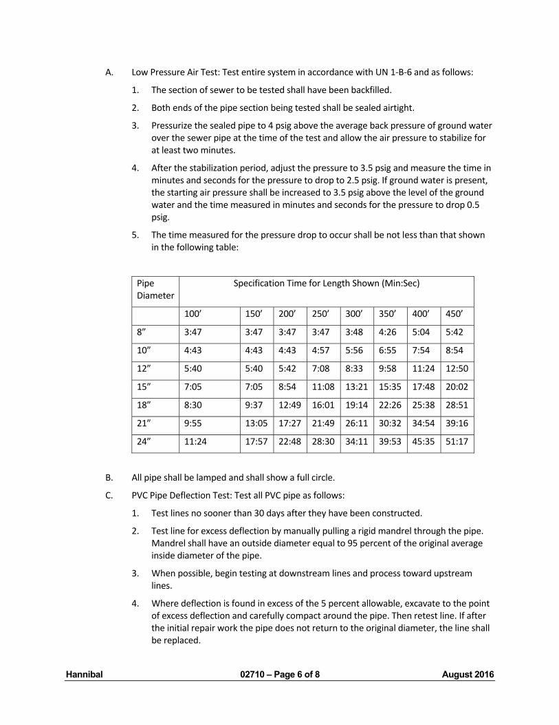
Hannibal 02710 – Page 6 of 8 August 2016
A. Low Pressure Air Test: Test entire system in accordance with UN 1‐B‐6 and as follows:
1. The section of sewer to be tested shall have been backfilled.
2. Both ends of the pipe section being tested shall be sealed airtight.
3. Pressurize the sealed pipe to 4 psig above the average back pressure of ground water over the sewer pipe at the time of the test and allow the air pressure to stabilize for at least two minutes.
4. After the stabilization period, adjust the pressure to 3.5 psig and measure the time in minutes and seconds for the pressure to drop to 2.5 psig. If ground water is present, the starting air pressure shall be increased to 3.5 psig above the level of the ground water and the time measured in minutes and seconds for the pressure to drop 0.5 psig.
5. The time measured for the pressure drop to occur shall be not less than that shown in the following table:
Pipe Diameter
Specification Time for Length Shown (Min:Sec)
100’ 150’ 200’ 250’ 300’ 350’ 400’ 450’
8” 3:47 3:47 3:47 3:47 3:48 4:26 5:04 5:42
10” 4:43 4:43 4:43 4:57 5:56 6:55 7:54 8:54
12” 5:40 5:40 5:42 7:08 8:33 9:58 11:24 12:50
15” 7:05 7:05 8:54 11:08 13:21 15:35 17:48 20:02
18” 8:30 9:37 12:49 16:01 19:14 22:26 25:38 28:51
21” 9:55 13:05 17:27 21:49 26:11 30:32 34:54 39:16
24” 11:24 17:57 22:48 28:30 34:11 39:53 45:35 51:17
B. All pipe shall be lamped and shall show a full circle.
C. PVC Pipe Deflection Test: Test all PVC pipe as follows:
1. Test lines no sooner than 30 days after they have been constructed.
2. Test line for excess deflection by manually pulling a rigid mandrel through the pipe. Mandrel shall have an outside diameter equal to 95 percent of the original average inside diameter of the pipe.
3. When possible, begin testing at downstream lines and process toward upstream lines.
4. Where deflection is found in excess of the 5 percent allowable, excavate to the point of excess deflection and carefully compact around the pipe. Then retest line. If after the initial repair work the pipe does not return to the original diameter, the line shall be replaced.

Hannibal 02710 – Page 7 of 8 August 2016
D. Repair or replace any line which fails any of the above tests, and retest.
E. Manholes shall be tested for exfiltration by plugging pipes in the manhole, filling the manholes with water, and after a one hour waiting period, measuring the change in water level over the next one‐hour test period. Exfiltration from the manholes shall not exceed 240 gallon per inch diameter per mile length per 24 hour day. If exfiltration is greater than allowed, make repairs and retest until exfiltration is within allowable limits.
F. All tests shall be witnessed by the Engineer.
3.3 HOUSE LATERALS
A. It shall be the Contractor’s responsibility to locate all house laterals not shown on the plans and to verify the location of the existing house laterals which have been shown on the plans. The Contractor shall reconnect all existing house laterals. All costs involved with locating or verifying the location of existing house laterals shall not be paid for separately.
B. All costs for the first five (5) feet of 6” pipe, cleanouts, and couplings/adapters required to reconnect existing laterals to the new pipe shall be included in one of the pay items for the appropriate size wye. The work shall be done in accordance with the Standard Construction Specifications and applicable District and County plumbing codes.
C. Connection of the house laterals to the new sewer may be made through the installation of “Wyes or Tees fittings”. All costs for these connections will be paid for at the unit bid price for wyes.
D. All existing lateral pipes which are to be disconnected shall be plugged. No separate payment will be made.
E. It shall be the Contractor’s responsibility to locate all house laterals not shown on the plans and to verify the location of the existing house laterals which have been shown on the plans. The Contractor shall reconnect all existing house laterals. All costs involved with locating or verifying the location of existing house laterals shall not be paid for separately.
F. Information provided on the project plans regarding wye locations have not been field verified. It is not the intent to reconnect any inactive service connections to the new sewer. The Contractor shall be responsible for determining if a service connection is active or inactive. No separate payment will be made for this work.
3.4 ADAPTERS AND COUPLINGS
A. At the direction of the Owner a connection of sanitary sewer pipe (4 inch through 15 inch) of dissimilar material or of different sizes or for the repair of sanitary sewer pipes of similar materials may be made by means of an approved connector or adapter of the compression or mechanical seal type as shown in the Standard Details.
B. The connector or adapter shall be manufactured of an approved pre‐formed elastomeric material conforming to applicable sections of ASTM Standards C425, C443, C564, and D3212. Couplings of the mechanical seal type shall have tightening clamps or devices made of 300 series stainless steel with a stainless steel shear ring and stainless steel hardware, as specified in ASTM A167. IF a stainless steel shear band is not used, a concrete collar as shown in the Standard Details is required.

Hannibal 02710 – Page 8 of 8 August 2016
C. The compression joint connector or adapter and flexible coupling shall be installed as recommended and specified by the manufacturer. Each connector and adapter shall bear the manufacturer’s name required markings.
D. All costs associated with the connection of pipe shall be included in the unit price pay items for pipe and not paid for separately.
END OF SECTION 02710
Hannibal 02720 – Page 1 of 3 August 2016
SECTION 02720
MANHOLES
PART 1 ‐ GENERAL
1.1 RELATED WORK IN OTHER SECTIONS
A. Section 02710 – Sewer Lines
PART 2 ‐ PRODUCTS
2.1 MATERIALS
A. Precast Concrete Manholes.
1. All manholes used on this project shall be precast concrete as shown on the Standard Details.
2. Precast concrete manholes shall be composed of sections manufactured in accordance with the latest revision of ASTM C478. The minimum compressive strength for the concrete for all sections shall be 4000 psi. All precast sections shall be manufactured with vibrated concrete (wet cast) and provided with an exterior waterproof coating.
3. Manhole sections shall have ends suitable for making a joint utilizing a rubber gasket or plastic rope gaskets such as Ram‐Nek or E‐Z Stik. The section ends, the joint and the gasket shall meet the requirements of ASTM Specificaiton Designation C443.
4. All pipe connections shall incorporate a flexible watertight jointing material such as the A‐Lok or Z‐Lock compression type joint, or approved equal.
B. Standard Manhole Frames and Covers
1. Manhole frames and covers shall be first quality gray iron castings. They shall be as manufactured by Neenah Foundry Company R1642 or approved equal. Provide machined bearing surface with self‐sealing gasket. Provide a 24‐inch diameter clear opening. All frames shall be bolted onto concrete cone with four 4‐1/2” bolts. Contractor also may drill and install four concrete wedge anchors ½ x 4”.
2. All castings shall be made of cast iron conforming to Class No. 35 of the current ASTM Specification A48 for gray iron castings. Castings shall be planned where necessary to secure perfectly flat and true surfaces. All castings shall be clean and free of scale, adhesions or inclusions.
3. It shall be the Contractor’s responsibility to furnish a frame which will fit the manhole opening.
C. Watertight Manhole Frames and Covers
1. Where noted on the Plans, the Contractor shall supply and install watertight manhole frames and covers. They shall be as manufactured by Neenah Foundry Company R‐1916‐F1 or approved equal. All frames shall be bolted onto the concrete cone section
Hannibal 02720 – Page 2 of 3 August 2016
with four 4‐1/2” bolts. Contractor also may drill and install four concrete wedge anchors ½” x 4”.
2. All castings shall be made of cast iron conforming to Class No. 35 of the current ASTM Specification A48 for gray iron castings. Castings shall be planned where necessary to secure perfectly flat and true surfaces. All castings shall be clean and free of scale, adhesions or inclusions.
3. It shall be the Contractor’s responsibility to furnish a frame which will fit the manhole opening.
D. Manhole Steps
1. Manholes steps shall be not less than 10 inches wide, and manufactured for use as manhole steps in accordance with OSHA Standards. Steps shall consist of a steel reinforcing bar encased in plastic. Manhole step details are shown on the Standard Details.
2. The steel reinforcing rod in the plastic step shall be 3/8 inch in diameter, encased with polypropylene plastic.
E. Manhole Stub and Stopper
1. Manhole stub and stoppers shall be of the same materials selected for the sewer pipe of that particular size, and in accordance with pipe material specifications in Section 02710, “Sewer Lines.”
PART 3 ‐ EXECUTION
3.1 MANHOLE CONSTRUCTION:
A. General
1. Manholes are to be built at locations as shown on the Plans or as directed by the Engineer, as rapidly as the construction of the sewer will permit. Manholes shall have the top of the manhole frame and cover installed flush with the existing surfaces unless otherwise noted on the plans. Manhole details are shown on the Standard Sewer Details.
2. The inverts of all manholes shall be shaped to the incoming and outgoing pipes and smoothly shaped from pipe to pipe to the top of invert at springline.
3. Manhole steps shall be set in place on the inside of the manhole, at the spacing shown on the Standard Details. The top step shall be not more than 2 feet below the top of the manhole.
4. Manholes shall be covered with standard cast iron frames and covers of the dimensions and materials herein specified. Water‐tight covers shall be sealed by means of a rubber gasket. All manholes with watertight covers shall have concrete manhole anchors constructed as detailed on the Plans.
5. Manhole frames shall be sealed to the top of manhole cone sections or grade rings utilizing a mastic sealer as specified for precast manholes in paragraph 2.1.A of this Section. The anchor lugs or mud ring on manhole frames shall fit securely against the inside opening in manhole cones or grade rings and bear against concrete. Grade
Hannibal 02720 – Page 3 of 3 August 2016
rings, if utilized, shall be sealed to the top of manholes utilizing a mastic sealer or a thin layer of grout. Grade rings shall not be used on the manholes designated with a watertight frame and cover and concrete manhole anchor.
6. Manhole pipe connection seals shall incorporate a flexible watertight jointing material such as the A‐Lok or Z‐Lok Manhole pipe seal, or approved equal which is installed per the manufacturer’s recommendations for the pipe materials used. Grouting of the pipe into the manhole will not be permitted.
7. Joints of precast manhole section shall be made utilizing a rubber gasket or an approved bituminous gasket. Joints shall be self‐centering. The gasket shall be the sole element utilized in sealing the joint.
3.2 MANHOLE TESTING
A. All manholes shall have a vacuum test in accordance with ASTM C‐1244 to assure water‐tightness before backfilling. The Contractor shall furnish all facilities required, including necessary piping connections, test pumping equipment, pressure gauges, bulkheads, regulator, and all miscellaneous items required. Calibration data will be supplied with all pressure test gauges. Certification of vacuum test gauge will be required from the gauge manufacturer. This certification and calibration data will be available to the Engineer whenever air tests are performed. Test each manhole and appurtenances after the complete installation. Stabilize the vacuum at 10” Hg (mercury) and avoid over pressurization. After pressure has stabilized, the gauge is allowed a maximum of 1” Hg drop during the test period. The required test period is one minute (minimum) for manholes up to 48 inches in diameter and two minutes longer for larger manhole diameters. If the vacuum test fails to meet the above requirement, repeat test as necessary after all leaks and defects have been repaired. Prior to acceptance, all constructed manholes shall satisfactorily pass the vacuum test. Exfiltration testing in accordance with ASTM C‐969 will be allowed in lieu of vacuum testing when submitted by the Contractor and approved by the Engineer. For exfiltration testing, allowable leakage limit is 200 gallons/inch of pipe diameter/mile of line/day when the average head on the test section is three feet or less. After plugging all inlet and outlet pipes, the structure shall be filled with water to the top of the manhole frame. After allowance for water absorption and refilling, if required, the leakage loss shall be measured over a timed test period as directed by the District. In any case, the testing time period for the exfiltration test shall be no less than one hour.
B. All visible leaks in manholes shall be repaired from the outside of the manholes using cement mortar grout or pressure grouted from the inside using chemical grouting procedures.
END OF SECTION 02720