september 2014 guidance accessible bus stop design · accessible bus stop design guidance for...
TRANSCRIPT

Accessible bus stop design guidance For consultation September 2014

0 | P a g e
CONTENTS
1. Introduction ............................................................................................... 1
2. Accessible bus services .......................................................................... 4
3. Bus stop locations.................................................................................... 8
4. Passenger waiting area .......................................................................... 13
5. Bus stop area .......................................................................................... 18
6. Bus stop layouts ..................................................................................... 19
7. Bus boarders .......................................................................................... 22
8. Bus bays or lay-bys ................................................................................ 25
9. Kerb profiles and heights ...................................................................... 27
10. Interactions with other street facilities ............................................... 28
11. Cycle facilities ...................................................................................... 29
12. Longer term issues .............................................................................. 31
13. References / Data sources .................................................................. 32
Figure 1: Street types .......................................................................................................... 2
Figure 2: Features of the bus stop environment .............................................................. 2
Figure 3: Passenger groups benefiting from low floor buses ......................................... 5
Figure 4: Bus stop layout objectives ................................................................................. 6
Figure 5: Relationship between bus and kerb .................................................................. 7
Figure 6: Considerations for bus stop locations .............................................................. 8
Figure 7: Bus arrival patterns ...........................................................................................10
Figure 8: Boarding and alighting zones ...........................................................................14
Figure 9: Centre of Footway Shelter .................................................................................15
Figure 10: Back to Street Shelter ......................................................................................15
Figure 11: Back of Footway Shelter ..................................................................................15
Figure 12: Kerbside approach with parking on approach and exit ................................20
Figure 13: Exit side of pedestrian crossing .....................................................................20
Figure 14: Exit side of junction .........................................................................................20
Figure 15: Full width boarder ............................................................................................23
Figure 16: Alternative full width boarder layouts ............................................................23
Figure 17: Multiple bus full width boarder .......................................................................23
Figure 18: Half width boarder ............................................................................................24
Figure 19: Bus bay arrangements.....................................................................................25
Figure 20: Amendment to existing bus bay .....................................................................26

1 | P a g e
This guide updates the ‘Accessible Bus Stop Guidance note BP1/06’ published in January 2006 and its predecessor documents. These updated guidelines have been developed in the context of the Equality Act 2010, the Mayor’s Transport Strategy and the Accessibility Implementation Plan. This document updates the original accessibility guidance to ensure it is both relevant and reflects changes in policy. Key additions and omissions include:
Criteria for an accessible bus stop
New chapters on ‘interaction of bus stops with other street facilities’ and ‘Cycle facilities’.
The removal of references to articulated buses and particular kerb types that are not specified for use by Transport for London.
With this updated version, we aim to provide all those involved in the construction of bus stops with design guidance that ensures bus stops are accessible to all, particularly passengers with disabilities. The guide will also assist highway authorities in the development of practical and affordable measures to improve accessibility at bus stops. The measures should be compatible with the particular characteristics of low floor buses deployed on the capital's road network. The introduction of low floor buses throughout London, fitted with ramps for wheelchair access, has led to a requirement for appropriate kerbside access at bus stops. Unless all stops along a bus route are equally accessible, passengers may be unable to board or alight a bus at their desired location and the potential benefits from low floor buses will be reduced. This hinders developing an inclusive public transport system. Bus stop design and location is recognised as a key element in the drive to improve the
quality of bus services. From an operational perspective, a well designed bus stop can provide significant benefits. The economic benefits will vary on a case by case basis, and normally be influenced by the volume of bus passengers. Route specific passenger journey data is available to inform designers in the form of boarding and alighting data, and this should be used rather than generic pan-London bus occupancy numbers. Bus passengers are also pedestrians at each end of the bus trip and all elements of their journey should be considered. The convenience and comfort of the waiting environment must not be overlooked. It is important to view the bus stop as an interchange, rather than simply a location along a bus route where buses stop, comprising only a post with a flag, and a cage laid on the road surface. The Mayor’s Roads Task Force (RTF), an independent body set up to consider the challenges facing London’s streets and roads, published their final report in July 2013. They set out key recommendations to conclude that a ‘one size fits all’ approach would not cater for the unique nature of London’s streets. In this context the interaction between the street and bus stop design is vital, particularly to ensure accessibility, inclusiveness and equality. This guide follows the lead of the RTF to give inclusive consideration to bus stop interactions with cycle infrastructure and street design.
1. Introduction

2 | P a g e
Figure 1: Street types To provide a wider context for design decisions the RTF established a framework of nine Street Types (Figure 1), each with a unique balance between “place” and “movement” function. This classification provides a unifying perspective across London within which the most important design elements influencing the bus stop environment should be considered, as illustrated in Figure 1. The bus stop environment contains a number of elements that need to be considered, as illustrated in Figure 2.
Figure 2: Features of the bus stop environment An accessible bus service is a critical element in delivering a fully inclusive society and bus stops are a vital link in this vision. TfL wishes to highlight this importance and part of the rationale in revising the bus stop design guidelines is to reiterate the wider issues relating to equality and inclusion. It should be remembered that kerbside controls and bus boarders are tools; the
objective is to ensure that the bus stop is fully accessible. Additionally, it is important to emphasise the need for: training for bus drivers on how to
approach and correctly use the bus stop; particularly when deploying the ramp for a wheelchair.
removing obstacles around bus stops as footway clearance is a criteria required for accessibility at bus stops.

3 | P a g e
planners and engineers to optimise the location, design and construction of bus stops; and
motorists and enforcement authorities to recognise the necessity for bus stops to be kept clear of parked vehicles.
The Street Type framework provided by the RTF indicates the relative significance of each location in terms of movement and place. The suitability of a particular design may be influenced by that significance as will expectations for the level of provision required. As such Street Types provide an overarching context to discuss the suitability of applying the design tools defined within this note. When reviewing individual bus stops, and their immediate environs, designers need to take account of the wide range of issues that are discussed within this guide. Whilst these guidelines provide assistance with the decision making process, it should be recognised that each site is a unique location, with different characteristics to be taken into account.
Bus Stop Accessibility A key Transport for London objective is to increase the number of accessible bus stops. 95% of all bus stops in London will be accessible by December 2016. For a bus stop to be fully compliant as an accessible bus stop the following criteria need to be met: Kerb>100mm – In order for a bus to deploy its ramp safely the ideal range in terms of kerb height is 125 – 140 millimetres, however 100 millimetres is the minimum for it to be compliant. Clearway in place – On borough roads a clearway is denoted by a thick solid yellow line (TSRGD 1025.1), each bus stop should have one of these along the length of the bus stop cage. This, in conjunction with the
timeplate (TSRGD 924), allows for the enforcement of the no stopping restrictions. The requirement for timeplates has now been removed for roads on the TLRN because the double red line at bus stop denotes no stopping Access free of impediments – This is a visual check of the area around the bus stop, including the surrounding pavement, to ensure that the bus will be able to deploy its ramp so that wheelchair users and people with prams can access the ramp.

4 | P a g e
Low floor bus users
Low floor buses reduce the height differential between the kerb and bus floor. Whilst they are generally seen as a means of improving accessibility for all passengers, mobility impaired passengers including wheelchair users benefit most from low floor buses. Research conducted by Transport Research Laboratory (TRL Report 271) has shown that passengers with pushchairs benefit greatly from the introduction of low floor buses. Thus, when designing bus stops for low floor bus access, the needs of all passengers should be considered.
Features of London bus services
The entire TfL bus network is operated using low floor vehicles. All buses have a single step entry, a low floor in the front part of the
vehicle, and either a sloping gangway, or step towards the rear, over the drive axle. Generally, they have front doors for boarding passengers and centre doors for those alighting, although it should be noted that the New Bus for London has three doors, all of which are used for boarding and alighting. Powered ramps are usually fitted to the centre door where wheelchair users may board and alight. Push buttons are provided for wheelchair users to alert the driver when the ramp needs to be deployed. Additionally, low floor buses are provided with the means of lowering, or ‘‘kneeling’, the bus suspension to reduce the step height at stops. This is provided at the passenger’s request and so is not automatic. The Big Red Book, a guidance manual provided to all London Buses drivers, states that the bus should pull up as near as possible to the kerb. Drivers are also told to kneel the bus if a passenger asks or if the driver can see a passenger needs it.
2. Accessible bus services

5 | P a g e
Figure 3: Passenger groups benefiting from low floor buses Bus stop layout objectives
The ideal bus stop layout will achieve the objectives shown in figure 3. The bus should stop parallel to, and as close to, the kerb as possible to allow effective use of the bus’
facilities. The critical dimensions to consider are the vertical height, or step height, from the kerb to the bus floor and the horizontal gap from the kerb edge to the side of the bus. A well designed bus stop will provide features which co-ordinate with the facilities of the low floor bus and minimise these two distances.

6 | P a g e
Figure 4: Bus stop layout objectives The size of the vertical gap between the kerb and floor of the bus will affect the gradient of the ramp when it is deployed. If this gradient is too severe some wheelchair users may be unable to enter or exit safely from the bus. Regulations under the Equality Act 2010 require buses to be capable of deploying a ramp, giving a 1:8 or 12% (12°gradient), onto a kerb range of 100mm - 140mm in height. This regulation, therefore, assumes a 'standard' kerb height of 140mm, which, although not the case universally, is the height that vehicle manufacturers are guided to apply in bus design.

7 | P a g e
Figure 5: Relationship between bus and kerb It is important to recognise that, when deployed on a 100mm - 140mm high kerb, the gradient of the ramp may vary. The major determinants include; the
type of ramp;
ramp length;
carriageway and footway crossfalls;
camber of the carriageway;
‘kneeling’ height of the bus floor (see figure 5); and
whether the bus is fully laden. It should be noted that with the ‘kneeling’ systems in common use, the reduction in step height achieved is not necessarily uniform along the side of the bus. The front door will be lower than the centre door if the ‘kneeling’ system operates on the front axle alone. Alternative configurations include tilting of the nearside of the bus and lowering of the entire vehicle. In the urban environment, there often exists a conflict between the demands for frontage servicing, short term parking and the need to protect a sufficient length of kerb space to allow buses to easily access a stop. As with previous guidelines, this document recognises the competing demands in London's busy street environment and retains the previous target benchmark of the bus stopping within 200mm of the kerb.
8 | P a g e
Introduction
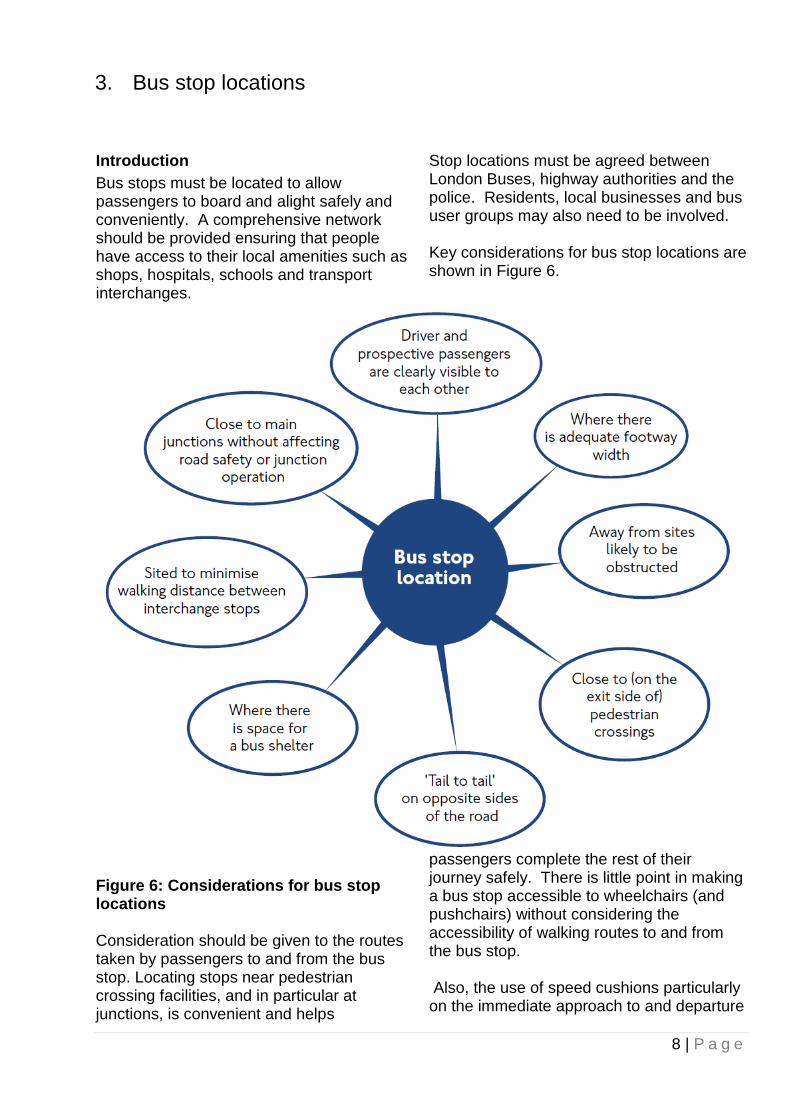
Bus stops must be located to allow passengers to board and alight safely and conveniently. A comprehensive network should be provided ensuring that people have access to their local amenities such as shops, hospitals, schools and transport interchanges.
Stop locations must be agreed between London Buses, highway authorities and the police. Residents, local businesses and bus user groups may also need to be involved. Key considerations for bus stop locations are shown in Figure 6.
Figure 6: Considerations for bus stop locations Consideration should be given to the routes taken by passengers to and from the bus stop. Locating stops near pedestrian crossing facilities, and in particular at junctions, is convenient and helps
passengers complete the rest of their journey safely. There is little point in making a bus stop accessible to wheelchairs (and pushchairs) without considering the accessibility of walking routes to and from the bus stop. Also, the use of speed cushions particularly on the immediate approach to and departure
3. Bus stop locations
9 | P a g e
from bus stops should be avoided as buses may wobble over this if not approaching correctly over the (1.6m) running channel due to parked cars. In particular there may be a risk of falling for passengers intending to alight who are walking within the bus as it traverses the cushion. It may also be necessary to provide additional dropped kerb crossings and/or crossing facilities in the vicinity of the stop as part of any bus stop improvements. This will need road safety auditing, although BSA schemes that do not impact on the road layout will not need a Road Safety Audit. . Where possible, the use of gullies in the position of the boarding and alighting zone should be avoided or fitted with a frame to ensure that the ramp when deployed is stable and passengers with high heels do not become trapped in the event they step into the carriageway before stepping on the bus, to avoid a trip. Accessibility should be considered in terms of the whole journey approach. Stop spacing
An ideal spacing for bus stops is approximately 300m - 400m, although a closer spacing in town centres and residential areas may be required to meet passenger requirements. Consideration should be given to improving spacing, and reviewing locations, particularly where interchange is an issue. Bus journey times are affected by the number of stops on a route and therefore a careful balance must be achieved. If it is proposed to relocate stops, an assessment of resulting benefits/impacts should be undertaken alongside consultation with stakeholders.
Stop capacity
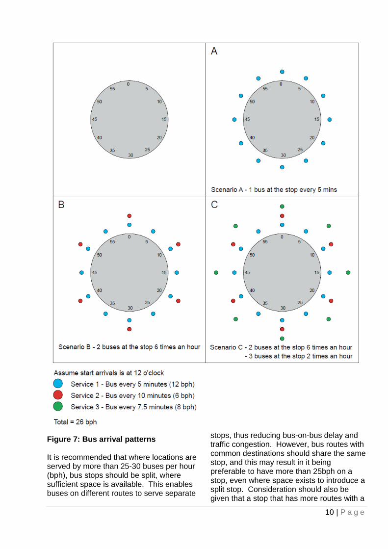
A 37m kerbside bus stop cage is normally sufficient for a frequency of 15 bph but inadequate for 45 bph, where space should be provided for more than one bus to access and serve the stop at the same time. Conversely, at bus stops where the number of buses serving the stop is much lower, a shorter cage of 25 metres should be sufficient, subject to swept path analysis demonstrating that a bus can achieve a position flush with the kerb. Note: Consideration must also be given to traffic management measures. The ‘clock-face’ diagram (Figure 7) overleaf/page xx indicates how the frequency of services influences the amount of space required at a stop. Consideration also needs to be given to the average boarding/alighting times. Scenario C shows that although at 26 buses an hour the stop in theory operates well below saturation capacity, if a dwell time of one minute per bus the stop is only occupied for 26 minutes, the likely arrival pattern of buses means that it is likely that some of the time more than one bus will be on the stop. It is recognised that at certain locations the number and frequency of bus services may be particularly high, as well as multiple requirements for kerbside space, and compromises may have to be made to the length of the cage, although this may impact on the bus’ ability to pull up close to the kerb. The Big Red Book advises drivers to stop within the cage markings, so only in exceptional circumstances should cage lengths be shortened.
10 | P a g e
Figure 7: Bus arrival patterns It is recommended that where locations are served by more than 25-30 buses per hour (bph), bus stops should be split, where sufficient space is available. This enables buses on different routes to serve separate
stops, thus reducing bus-on-bus delay and traffic congestion. However, bus routes with common destinations should share the same stop, and this may result in it being preferable to have more than 25bph on a stop, even where space exists to introduce a split stop. Consideration should also be given that a stop that has more routes with a

11 | P a g e
lower frequency is likely to have more times with multiple buses at the stop than a stop with fewer routes at a higher frequency. Buses per hour is only one measure of the capacity of a bus stop, with total passenger numbers (and hence dwell time), and ease of pulling out from the stop also important. Decisions on merging or splitting stops should therefore be based on observations of the actual performance of the stop rather than just looking at buses per hour.
Bus stops and traffic signals
A bus stop in advance of the signals can have safety implications, as a driver’s forward visibility will be reduced. When at a bus stop, a bus can obscure the nearside signal or a pedestrian leaving the footway to cross the road. Passengers often prefer the bus stop to be as close to the junction as possible. Ideally, bus stops should be located on the exit side of junctions, where the effect on saturation flows is generally less than stops sited in advance of signals. There are locations where a bus stop is better sited on the approach side of the junction to serve interchanges and attractions or before routes diverge. If a stop is sited on the approach side of the traffic signals, there is a requirement for the primary signal to be visible for at least 70m in an urban environment. Stationary bus in advance of traffic signals will interfere with signals detection if placed less than 40m from stop line. National guidance requires a
minimum of 20m of unobstructed space from traffic signals. Traffic capacity implications should be considered if a bus stop is located in advance of traffic signals. If a bus stop is proposed close to traffic signals mitigating measures may be required; For example central island with additional signal, modified lane markings or a different traffic signals sequence. These are all site specific measures which would require consultation with the relevant traffic signals authority. If there are proposed changes in kerb alignment (e.g. bus boarders) or traffic lanes are to be realigned, existing loops (SCOOT, MOVA or X, Y or Z loops) on the approach to junctions may need to be re-cut or repositioned. ‘Hail & Ride’
Fixed stops are preferable to Hail and Ride services as they are more accessible. Fixed bus stops can be protected with bus stop 'cages', so that buses are physically able to pull up close to the kerb, assisting passengers to board or alight. Hail and Ride sections are used where it is difficult to site bus stops but where the presence of a bus service brings benefits to passengers and residents. However, these services can help older and disabled people as there is a shorter walk to the boarding point’. Outlined below are options to improve accessibility of ‘Hail & Ride’ bus services. Option 1 – Conversion to fixed stop On some services there may be a strong case for conversion to fixed stops; for example, where services have grown in patronage and buses are making frequent stops, or where passenger demand is concentrated at identifiable points. Passenger surveys will assist in determining the appropriate solution. Providing fixed stops provides better customer information and provides a certain location for passengers, which in particular

12 | P a g e
benefits passengers with learning difficulties. This also helps bus operations as it is easier to regulate bus services when there are formal bus stops. This is Transport for London’s preferred solution. Option 2 – Retention of ‘Hail & Ride’ sections of route It may be appropriate to retain ‘Hail & Ride’ operation:
On lightly used services;
On routes where passenger demand is very scattered; or
Where local conditions make installation of bus stops difficult or sensitive
Where ‘Hail & Ride’ is retained the following options should be considered to provide improved accessibility. Option 2a – Provision of information for passengers where ‘Hail & Ride’ sections are already accessible Information posts, which display a bus timetable and other information, can be provided at locations which offer good accessibility to and from buses. However, these posts are not fixed bus stops, they do
not have a bus stop flag and buses can still stop at other safe points. The benefits of these information points are that they provide re-assurance to passengers that buses serve the route and they offer a source of information, such as the frequency and destination of buses. The posts also encourage passengers to congregate, rather than waiting at short distances from each other and expecting the bus to make several stops. The advantage for disabled people is that the benefits of ‘Hail & Ride’ are retained. Option 2b – Provision of accessible points along ‘Hail & Ride’ sections of route It may be appropriate to install accessible boarding and alighting points at intervals along ‘Hail & Ride’ sections of route. Accessible points could, for example, consist of a simple (2m wide x 4m) bus boarder to provide full accessibility whilst minimising the impact on the local environment. Parking restrictions for accessible points without bus stops would require a Traffic Regulation Order, as bus stop clearways cannot be installed without a bus stop flag. Information posts can also be provided, where appropriate, to explain to passengers that a section of route is ‘Hail & Ride’.

13 | P a g e
Bus stop post and flag
When the features of the buses using a stop are known, consideration should be given to the passenger waiting area. The layout of the passenger waiting area should be based around the position of the bus stop flag. This will dictate the design of the highway markings (clearway or cage) and the street furniture on the pavement. Please see chapters 5 & 6 for further details on highway design. The flag indicates to passengers where they should wait and serves as a marker to drivers to indicate where the bus should stop. These guidelines are based on the bus stopping with the rear of the front doors in line with the flag and passengers boarding from the downstream side of the flag. However, please note that, the Big Red Book states that drivers should adhere to the position of the bus cage rather than the position of the flag. In some circumstances it may be appropriate to combine the bus stop flag with street lighting, although this should be agreed between TfL and the owner of the lighting column. Waiting area layout
Most buses in London are configured with a powered ramp at the centre door. On shorter buses, without a centre door, the ramp is situated at the front door. Sufficient unobstructed space is required at these doors for the ramp to be deployed. On the footway where the stop is located, boarding/alighting areas should be kept clear of all obstructions such as litter bins, telephone boxes and sign posts. The length of clear footway required is defined by the width of the doors. The width of footway needed is defined by the space required for a wheelchair or pushchair to manoeuvre. The DfT’s Inclusive Mobility Guidelines state that a skilled manual wheelchair user should be able to complete
a 360° turn in a space of 1500 mm x 1500 mm, therefore this is the minimum physically possible space. Typically footway widths should be a minimum of two metres in existing conditions. It may be difficult in existing situations where there are physical constraints to deliver this basic level of physical accessibility. A minimum of three metres should be provided in new developments to allow for through pedestrians and people waiting. Consideration should also be given to wider footways in busier areas to segregate passenger waiting at stops and regular pedestrian flow.
4. Passenger waiting area

14 | P a g e
Figure 8: Boarding and alighting zones Figure 8 shows the suggested bus stop layout with boarding/alighting zones, which must be kept free of all street furniture. The area around the front door is 2 m long, the area around the middle doors is 4m long and the area at the back door (where applicable) is 4m long. However, for simplicity, it is recommended that street furniture is not positioned throughout the length of footway where boarding and alighting is expected. Additionally, street furniture located in the waiting area can reduce the available space close to the stop. It is also important that the stepping height is minimised along the length of the clearway. Dropped kerbs for driveways pose particular
problems. Where there is a series of dropped kerbs it will be necessary to position the flag carefully between them. By adopting a boarding/alighting zone, problems for ramp deployment and stepping to and from the bus can be minimised. At stops to be used simultaneously by multiple vehicles the same boarding/alighting zone principle should be adopted. It is more difficult to recommend a standard design for a second bus because of the possible variations in stopping position and vehicle type. Consideration needs to be given to the distance between the rear of the first bus and the front of the second.
Bus passenger shelter
Bus shelters play a valuable role in delivering a broader measure of accessibility. The shelter will protect people from poor weather, with lighting to help them feel more secure, Seating is provided to assist ambulant disabled and older passengers. Countdown bus passenger information is currently included at over 2500 sites across London. Every Bus Stop also has a unique code displayed which passengers can text or use the TfL website to receive bus journey time information. They also provide important opportunities to consolidate street furniture (maps, signage) into a single structure. Figure 9-11 illustrate three general layouts for the bus passenger shelter. The ‘centre of footway’ layout (see figure 8) enables passengers to shelter, see approaching buses and board with ease. In addition, this layout, if on the approach side of the stop, allows wheelchair users who may wish to wait by their boarding position at the centre doors to be protected from the weather. Where the New Bus for London operates three door boarding configuration, this layout helps to spread boarders between the doors.

15 | P a g e
Figure 9: Centre of Footway Shelter Other arrangements may be used where footways are narrow or other site constraints dictate. The ‘back to street’ layout (see figure 9) can encourage passengers to stand upstream of the shelter so that they can see and board the bus more easily. The ‘back of the footway’ option (see Figure 10) is only appropriate where access to adjoining buildings can be maintained.
Figure 10: Back to Street Shelter
Figure 11: Back of Footway Shelter The design of the shelter may affect its positioning on the site. Shelters with a half width or no end panel on the bus approach side are recommended, because this improves visibility. TfL standard shelters generally consist of between 1 and 4 panels each of 1.3m length, with end panels of either 1.3m (full width) or 0.65 (half width). Roof overhangs can affect overall shelter positioning, but narrower variants are also available and TfL will advise on these issues. Lighting within the shelter can help to improve perception of personal safety and access to information. This will be provided wherever possible.
Footway width and pedestrian flows
The passenger waiting area where the passengers board and alight needs to be designed to allow sufficient space for the stop infrastructure, such as shelters, as well as pedestrian through movement. Research has shown that pedestrians will generally cope well with busy conditions, but some simple interventions can make the pedestrian environment more comfortable. Please refer to the TfL ‘Pedestrian Comfort Guidance’ and the advice on the waiting area layout earlier in this chapter. At some locations it may be necessary to widen the footway and this can often be achieved through the provision of a bus boarder (See chapter 7).

16 | P a g e
Figure 8 shows that the ‘centre of footway’ shelter layout should leave at least 2.7m (3m is preferred) between the kerb edge and the rear of the shelter for wheelchair users to manoeuvre. The gap between the shelter and the rear of the footway in busy conditions should have an unobstructed width of at least 2m. Therefore, a footway width of 3-5m is recommended (depending on pedestrian flows). ‘Back to street’ and ‘back of footway’ (figures 9 & 10) layouts also need to leave an unobstructed width of at least 2m for pedestrians. Larger unobstructed widths are recommended, but where unobstructed widths of over 3m can be achieved, a ‘centre of footway’ shelter configuration should be considered instead. ‘Back of footway’ layouts with large widths will make it difficult to board the bus as boarding passengers may conflict with pedestrians walking along the footway and increase bus stop dwelling time. Footway widths are effectively reduced by street furniture such as telephone boxes, lamp columns, litter bins and parking ticket machines. Observations suggest that bus passengers have a tendency to wait for a bus in a linear pattern, adjacent to the road or to the back of the footway. At busy bus stops, queues can form upstream of the bus stop flag and therefore, unobstructed areas should be created within the entire zone where possible, by moving street furniture downstream of the bus stop, rationalising it or removing it altogether. This will help visibility of approaching buses as well as increasing pedestrian space. A simple audit of features in and around bus stops should aim to:
Reduce street clutter;
Optimise bus stop location including spacing;
Optimise shelter location; and
Consider other boundary effects such as ATMs
When designing accessible bus stops for a retail area, or other locations where
pedestrian flows are high, pedestrian counts should be undertaken at peak times such as Saturday 10am to 5pm and/or 12pm to 2pm during the working week. For areas where there is large public transport interchange during the week pedestrian counts should be undertaken between 7am and 10am and 4pm and 7pm. Waiting area environment
Designers should give consideration to other aspects of the passenger waiting area, not just those primarily related to access between the footway and bus. The environment of the passenger waiting area is an important component of passengers' perception of the quality of the bus service and safety. Crime and the perception of crime can influence the environment of bus stops and consequently have an impact on the desirability of the location. There is a statutory duty for all highway authorities under S.17 of the Crime & Disorder Act 1998 to do all it can to prevent crime in all of its undertakings, which includes the provision of bus stops and shelters. Poorly located street furniture can lead to an increase in crime and fear of crime. It is therefore necessary that a crime and disorder assessment be undertaken for all new bus stops and shelters. This can be provided by TfL’s Enforcement and On-street Operations, and will help highway authorities to show that crime prevention has been considered carefully A number of other issues should be considered: Street lighting; inadequate, street
lighting can contribute to issues of personal security. Good levels of illumination should be provided at bus stops.
Litter; A clean passenger waiting area
improves the passengers' environment. Litter bins should be provided but care needs to be taken in locating litter bins to reduce nuisance, such as smells and flies, potential for anti social behaviour
17 | P a g e
and avoid obstruction to pedestrian and passenger movement. They should also be emptied regularly by the local authority.
Statutory undertakers' equipment;
Positioning of bus stop flags and passenger shelters can be affected by underground utilities. Service covers can also create long term problems at the bus stop owing to access requirements to the equipment. Consideration should be given to the boarding/alighting zone to avoid access difficulties during maintenance works. However it is acknowledged that service covers are likely to be present at many bus stop locations.
Drainage; Poor drainage, resulting in
water ‘ponding’ on the footway around the passenger waiting area or at the carriageway kerbside, can affect the passenger environment. Ponding may also result from defective carriageway repairs, rutting or blocked drains. In freezing conditions footway ponding can be particularly dangerous. Ponding at the kerbside can result in passengers being splashed by passing traffic (or the bus) and it is, therefore, important that good drainage is provided and that footways in the vicinity of the bus stop are level to ensure surface water drains off efficiently.

18 | P a g e
Bus stop cage
The bus stop marking on the carriageway, often referred to as the bus 'cage', (Traffic Signs Regulations and General Directions (TSRGD) 2002 diagram 1025.1), is used to define the limits of the bus stop. The purpose of the bus stop cage should not merely be seen as identifying a stopping point. The bus stop cage has four distinct and important objectives – it defines an area of the carriageway where the bus can undertake the following unobstructed: approach; straighten up; stop and; exit It is a key requirement that a bus stop cage marking is provided and the area defined by the cage is unobstructed to allow easy entry and exit for the bus. The aim is that buses pull up within of 200mm from the kerb. Layouts to achieve this are illustrated in Chapters 6 - 8. The length of the bus stop cage will vary depending on the highway layout, the size of buses serving the bus and number of buses per hour using the stop. Bus stop cages are usually 3m wide; however, designers should be aware that the
TSRGD 2002 does allow some variation in road markings (TSRGD 2002, Article 12 Table 2). The marking can be reduced/increased by up to 10%. This allows cage widths of 2.7m to be introduced. Experience has shown this can be useful where carriageway widths are reduced, and there is some evidence to suggest that narrower 2.7m wide cages encourage bus drivers to stop closer to the kerb. Bus stop clearways
Within the cage area, no stopping by vehicles other than buses, should be permitted. On borough roads a clearway marking must be provided in accordance with TSRGD diagrams 974 and 1025.1. Bus stops located on the Transport for London Road Network (TLRN), are generally marked with double red lines. In some cases a wide red clearway line is provided to indicate that only buses can stop to prohibit taxis from setting down and picking up. These have been successful in reducing the number of conflicting movements between buses and other vehicles, particularly, taxis.
5. Bus stop area

19 | P a g e
Introduction
Bus stops unobstructed by kerbside activity are rare and it is usually necessary to find a means to sufficiently encourage motorists to keep the bus stop clear. As discussed in Chapter 5, generally all bus stops should have a marked cage as per TSRGD 2002 diagram 1025.1 with stopping restrictions operating 24 hours a day. Figure 12 shows layouts for 12m rigid buses where the bus stop has parking bays on both the approach and exit sides of the stop. The clear kerbside space is required to allow convenient and efficient bus access to within 200mm of the kerbside. 37m is the recommended bus cage length where parking is located either side of the stop and should be provided wherever possible. 25m lengths have been used however this length of cage does not provide enough space to smoothly pull up to within 200mm of the kerb to allow ramp deployment, 33m is the minimum space required to allow ramp deployment. The cage length required will also depend on the width of waiting and loading boxes on the approaches/exits. Where wider loading boxes are situated on the approach/exit then additional space is required because of the increased lateral movement. It is possible to reduce the cage length and still ensure a bus can access the bus stop. There are two convenient locations for bus stops where this can be achieved: the exit side of a pedestrian crossing
(Figure 13); and the exit side of a junction (Figure 14). These two layouts assist bus access whilst minimising the length of bus stop clearway.
They also have the advantage of placing stops near to where passengers may wish to cross the road. Safety issues must always be considered when adopting such designs. It is important to plan the cage size for the frequency of buses; otherwise following buses could block the crossing or side road (see Chapter 3 for further information). It should be noted that buses are permitted to stop on the exit side of zig-zag markings at Pelican and Zebra crossings to pick up or set down passengers. Most junctions on bus routes have some kerbside controls. However, problems can occur as a result of vehicles stopping between the cage and junction, even with kerbside restrictions. In practice marked bus cages with stopping restrictions are more effective at discouraging vehicles stopping in this area and are easier to implement. An extension to the cage to prohibit stopping on the approach is shown in Figure 11. Any relocation of the stopping position of the bus closer to the junction should have regard to visibility for drivers of vehicles leaving the side road. While a bus using the stop is a temporary obstruction, the bus stop post/flag, passenger shelter and waiting passengers should not unduly obscure sight lines.
6. Bus stop layouts

20 | P a g e
Figure 12: Kerbside approach with parking on approach and exit
Figure 13: Exit side of pedestrian crossing
Figure 14: Exit side of junction Bus manoeuvres
At locations where buses often have to manoeuvre around parked vehicles to pull up to and away from the stop, designers need to understand the implications of reducing the cage dimensions illustrated in Figures 12 to 14. A clear exit distance of 9m is recommended as the minimum necessary for buses to leave the stop and rejoin the general traffic
lane without the rear of the vehicle overhanging the kerb in the vicinity of waiting passengers. Exceptionally, in a highly constrained situation, this dimension could be reduced to an absolute minimum of 7m. Alternative solutions
There will be situations where none of the kerbside designs illustrated can be implemented without seriously affecting existing kerbside activity or general traffic operations. The issue often arises at busy

21 | P a g e
stops, which require a very long length of kerb to be kept free from any other activity. In many cases, stop accessibility will be hampered by legal or illegal waiting or loading on the approach to the bus stop. In such cases, it may not be physically possible for the rear of the bus to manoeuvre close to the kerb. In other situations, site constraints prevent conventional layouts from being implemented. Situations that cause problems for the siting of conventional kerbside bus stops include: where there are loading or parking bays
which cannot be moved without causing undue inconvenience for frontage users; and
where existing restrictions are neither observed nor effectively enforced.
In such cases a solution may be to alter the kerb line to assist bus access; e.g. a bus boarder.

22 | P a g e
Bus boarders
Bus boarders are generally built out from the existing kerb line and provide a convenient platform for boarding and alighting passengers. There are two conventional types of bus boarder, full width and half width. There are also variations on the bus boarder concept such as 500mm build-outs in the downstream section of bus bays. Care should be taken when building bus boarders that the necessary drainage has been provided. The full width boarder offers by far the best solution for both bus and passenger access whilst minimising the kerb length required. Full width boarders also serve to upgrade the image of the bus by providing a waiting area that can be separated from the adjacent pedestrian flow, and thus move towards the standards achieved by tram and light rail systems. Full width boarders
A full width boarder should project far enough into the carriageway for the bus to avoid manoeuvring past parked vehicles. For cars this should be at least 2m and a minimum of 2.6m where goods vehicles/vans are stopping. The length of the boarder will depend on the vehicle types that serve the stop in addition to the bus frequency. Figure 15 shows typical full width boarders. The length of kerbside space required can be reduced by providing a shelter, open towards the kerb, on the existing footway (Figure 16). Where smaller midi type buses serve the stop, and no passenger shelter is provided, it is possible to implement a boarder only 3m long (Figure 16). The benefits of a full width boarder are that it: minimises the kerbside space required; deters illegal waiting or loading
maintains the place of the bus in the traffic stream;
allows the bus to line up parallel to the kerb, largely without manoeuvres;
reduces boarding/alighting time; reduces overall time spent at the bus
stop; and creates additional footway space for
passengers to wait in shelter and allows regular pedestrian flows to continue unhindered.
The full width boarder keeps the position of the bus in the traffic stream, simplifying access and improving bus reliability, as the bus is not delayed waiting to rejoin the traffic stream. Full width boarders should not be used where the frequency of buses or their dwell times will cause delay to following buses and significant delays to general traffic. There may also be circumstances where, for safety reasons, it may not be appropriate to encourage an overtaking manoeuvre by other traffic, such as near the brow of a hill or an approach to a refuge/ island. The design of boarders should provide increased opportunities for the provision of passenger shelters. When making any changes to kerb lines, designers should consider the impact on cyclists as abrupt deviations in alignment can create pinch-points for two wheelers with general traffic. Bus boarders should therefore be designed to allow cyclists sufficient space to manoeuvre and avoid unduly sharp deflections on the approach to the build out so that cyclists have sufficient time to move into a primary position. Layouts for bus boarders to cater for multiple vehicles stopping at a single stop are provided in Figure 17.
7. Bus boarders

23 | P a g e
Figure 15: Full width boarder
Figure 16: Alternative full width boarder layouts
Figure 17: Multiple bus full width boarder Half width boarders
The half width boarder is often a useful compromise design. The build-out from the kerb can range from 500mm up to the width of a full boarder, although they are
commonly 1.0 - 1.5m wide. They should be used where frequent delays to other vehicles are to be avoided or where a full width boarder would place the bus in, or too close to, the opposing traffic stream. As half width boarders are a compromise design, they use more kerb space, as some manoeuvring of the bus is required (Figure 18). Half width

24 | P a g e
boarders retain some of the advantages of full width boarders, as they still deter illegal waiting or loading close to or within the bus stop cage and the prospects of the bus stopping close to the kerb are improved.
In circumstances where a layout has to cater for more than one bus stopping at the same time, provision should be made for the second bus to pull out past the first bus and for all doors of each vehicle to have clear access, unobstructed by street furniture.
Figure 18: Half width boarder

25 | P a g e
Bus bays (or lay-bys) present inherent operational problems for buses and they should not be used unless there are compelling safety or capacity reasons. However, in circumstances where provision of a new bay is required the layout in Figure 18 is recommended. This design incorporates a build-out to allow buses to turn tightly into the bay. In circumstances where two or more buses may require access to the bay at one time the stop area will require lengthening. As discussed in Chapter 5, a bus cage with 24-hour stopping controls, to prevent waiting or loading in the stop area, is recommended at all bus stops (as shown in TSRGD diagram 1025.4). There may also be a need to prohibit waiting or loading on the approach to, and exit from, the bay. There are many bus bays in use and the layout of can prevent buses from reaching the kerb effectively.
Figure 17 shows modifications to bus bays that can improve bus access to the kerbside. Designers should note that with these layouts, the bus protrudes into the nearside lane and amendments to traffic lane widths might be required. An alternative solution is to fill-in the bus bay completely, providing additional footway space that can be tailored to the boarding and alighting characteristics required. At locations where there is persistent parking in the bay, another variant is to fully fill a section of the bay, enabling the bus to stop on the main carriageway, whilst retaining a shorter bay for loading activity (see Figure 20). As can be seen from a comparison of Figures 20 and 21 with Figures 15 to 18, bus bays inevitably sterilise a far greater kerb length than any type of bus boarder.
Figure 19: Bus bay arrangements
8. Bus bays or lay-bys

26 | P a g e
Figure 20: Amendment to existing bus bay
27 | P a g e
Kerb heights
For new facilities, highway authorities and developers should aim to provide a kerb height of 140mm high, as this allows for future road resurfacing. Existing Kerb heights of between 100mm and 140mm high are unlikely to require alteration. However, where kerbs are already being altered at bus stops e.g. to build a bus boarder, consideration should be given to the use of higher kerbs to reduce the step height and reducing the gradient of the ramp deployed for wheelchair access. This will improve access for all bus users including disabled people. Where increased kerb heights are being considered to reduce step heights, the ground clearance of buses must be taken into account. Although bus stop layouts have been designed to avoid the need for buses to overhang the kerb on arrival or departure, this may occur at particular sites and can cause wheel damage. The kerb form is also important to consider. It is sometimes difficult for bus drivers to position their vehicles close to kerbs of traditional design; they are not easily seen from the drivers cab position and the driver will wish to avoid damage to the vehicle, particularly with 90 degree cornered kerbs, which are less sympathetic to wheel damage. It is therefore recommended that smooth angled face kerbs should be considered, particularly at new developments. Carriageway and footway crossfalls Where kerb heights are changed, carriageway and footway crossfalls will need to be carefully considered. As a general rule, carriageway crossfalls in the region of 1 in 40, or 2.5%, should not present any additional difficulties for low floor buses. For carriageway crossfalls steeper than 2.5%, regrading of the carriageway should be considered.
Footway crossfalls are also important and a steep backfall from the kerb is undesirable. A gradient of no more than 1 in 25 or 4% is suggested. To achieve this, designers may have to regrade lengths of footway to maintain adequate crossfalls or introduce complex drainage arrangements. A common problem with bus boarders is that works are only undertaken on the build-out, leading to steep crossfalls. Ideally, footways should be regraded to align from the back of the footway but this can add considerably to the cost of works. In all cases where levels are being altered, careful consideration must be given to adequate drainage of the site, particularly in relation to adjacent properties.
9. Kerb profiles and heights

28 | P a g e
The design approach to streets is continually evolving in London. In recent years there has been a greater recognition within guidance documents for the need to transform the quality of streets. To ensure that the design of our streets receives a consistently high level of care and attention, Transport for London (TfL) has written Streetscape Guidance. The Guidance has been developed for the Transport for London Road Network (TLRN); however the principles can be applied to all roads in the Capital.
The RTF Street Type framework takes account of local and network priorities, and aims to guide policy and investment decisions, to provide a basis for allocating road space. This can also be used as a means of establishing the level of design provision that users can expect from a place. The RTF highlighted a clear and compelling agenda for change in London. It noted that while progress has been made in recent years, there are many pressing – and interrelated – accessibility challenges ahead which are being directly addressed through this revised guidance. The RTF's recommendations, and the commitments made in TfL's response, were made to ensure that the design of our streets receives a consistently high level of care and attention. For this reason the Transport for London Streetscape Guidance is continually
being developed to ensure the Transport for London Road Network (TLRN) maintains the highest levels of accessibility. The principles outlined by the RTF and specific TfL guidance can be applied to all roads in the Capital. They clearly highlight how the interaction between street and bus stop design is vitally important, particularly to embrace accessibility, inclusiveness and equality. Shared and level surface schemes Shared and level surface schemes can have an impact on the accessibility of bus stops. All stops need to be equally accessible to enable all passengers to board and alight at their desired location. The removal of kerbs increases the step height from the footway to the bus and has a negative impact on the effective deployment of the bus passenger ramp. When designing shared or level surface schemes where bus stops infrastructure is in existence, particular attention is needed to minimise creating trip hazards by also ensuring adequate surface contrast for visually impaired people, as well as drainage and suitable lighting around the stop. An example where accessible bus stop infrastructure has been maintained within a level surface scheme is Exhibition Road. The Royal Borough of Kensington & Chelsea implemented a fully accessible level surface space on Exhibition Road with reduced traffic congestion and more room for pedestrians.
The design is such that there are no kerbs except at two locations where “platforms” have been built and corduroy paving is used to delineate the space for bus stops. It is important to recognise that design for bus stops in shared or level surface schemes should be site specific. Designers should therefore consult TfL at an early stage to ensure suitable advice is provided.
10. Interactions with other street facilities

29 | P a g e
More and safer cycling is a key TfL objective. Within the Mayor’s Transport Strategy there is a target to see 400% growth in cycling by 2026.
One key area of potential conflict and discomfort for on-carriageway cyclists is the bus stop when occupied by a bus or buses. At these locations cyclists need to position themselves so that they can be seen by bus drivers when overtaking stationary buses, and particularly when buses wish to pull into or out of the bus stop. The carriageway at bus stop locations should be designed in such a way that cyclists can approach and pass a stationary bus safely and comfortably. The preference is for bus or nearside lanes to be of sufficient width to enable cyclists to pass a stopped bus while staying within the lane. When off-carriageway cycling is provided for, off-carriageway cycle facilities need to be designed to minimise conflict with pedestrians and maintain accessibility for all bus passengers. There are a variety of potential interventions to reduce risks for cyclists at bus stops. These can include cycle lanes and tracks around bus stops and bus stop bypasses. When designing off-carriageway facilities for cyclists at bus stops consideration should be given to the unique features of any site including the following factors where applicable:
Safety of vulnerable bus passengers
Speed of cyclists approaching any
potential area of conflict
Ensuring crossings across any cycle
facility are accessible
Amount of passengers alighting and
waiting at the stop
Width of the pavement, pedestrian
flows and frontage uses
Frequency of buses using the bus stop,
and the number of buses that are
likely to be standing at any one time
Retaining bus shelter facilities
Bus ramp being able to deploy onto the
island and waiting wheelchair users
are able to access the ramp form the
waiting area
Lighting
Intervisibility, including through bus
stop shelters
Number of cyclists and potential growth in cyclist numbers
Kerb Heights
Drainage
Surface material and width of the cycle bypass
Future maintenance
Proximity to traffic signals
Bus Stop cycle bypasses have been in existence for a number of years, particularly on cycle tracks on footways in Outer London. The Cycle Superhighway 2 extension in Stratford introduced a new trial
11. Cycle facilities

30 | P a g e
design which introduces a cycle bypass at carriageway level with a bus stop island accessed by a raised crossing. Research into the effectiveness and customer experience of these is currently ongoing, as well as off highway trials. Results from these will inform future guidance on measures to be installed.
The London Cycling Design Standards, and other associated guidance, should be consulted for technical design guidance for the design of any cycling measures.

31 | P a g e
Maintaining Bus Stop Accessibility
TfL and the boroughs are investing considerable money, time and effort to make London's bus stops accessible. This investment and the resulting increased accessibility for bus passengers needs to be maintained. Small changes to the bus stop environment can make bus stops inaccessible. For example, the relocation of a litter bin or an advertising board into the bus entry or exit area may prevent a ramp being deployed. Highway authorities need to be aware of the impacts of any interventions such as the positioning of street furniture or changes to the bus stop kerb. Any intervention in the bus stop area that prevents a bus being able to pull up parallel to the kerb and deploy its ramp should be avoided. Maintenance
TfL is responsible for the bus stop flags and the majority of bus passenger shelters, local highway authorities have responsibilities, for maintenance of bus stop areas. This can include street cleaning, maintenance of the
footway and carriageway surfaces in the vicinity of the bus stop, winter maintenance etc. The carriageway, and potentially the kerb, in the vicinity of the bus stop are subject to particular stresses from the repeated manoeuvres of buses. Materials used in these areas should be durable and any faults quickly remedied. In the course of normal maintenance routines, carriageways will be resurfaced using a variety of methods. During resurfacing it is crucial that the kerb height at bus stops is maintained or improved. It is common for the general level of the carriageway to rise with successive surface repairs. This not only increases stepping heights and ramp gradients, to the detriment of passengers, but also increases crossfalls, causing additional problems for buses and reducing the efficiency of draining surface water. Enforcement
Many Boroughs now use CCTV to enforce Bus Stop Clearways and waiting/ loading restrictions, and this can contributes to improving compliance
.
12. Longer term issues

32 | P a g e
Barham P. et al. (1994). ‘Accessible Public Transport Infrastructure - Guidelines for the Design of Interchanges, Terminals and Stops’, Mobility Unit of the Dept. of Environment, Transport and the Regions and the Passenger Transport Executive Group The Bus Priority Working Group (N.I.) (1997). ‘Bus Stops - A Design Guide for Improved Quality’, Translink and Dept. of the Environment for Northern Ireland Dejeammes M. (1997). 'Accessible Low Floor Bus - System Approach in France', Transportation Research Record 1604, pp 163-169 Department for Transport (2002). ‘The Traffic Signs Regulations and General Directions’ DETR (1998). ‘Guidance on the Use of Tactile Paying Surfaces’ Disabled Persons Transport Advisory Committee (1997). ‘Recommended Specification for Low Floor Buses’ Hall S, and Desyllas J (2006). ‘Bus stops – how peoples actually use them ad the
implications for design. Association for European Transport and contributors Institution of Highways and Transportation (1997). ‘Transport in the Urban Environment’ Lavery I. and Davey S. (1996). 'The Pedestrian Environment - The Achilles' Heel of Travel by Low Floor Bus?', Proceedings of Seminar F, PTRC Roads Task Force (2013), ‘The vision and direction for London’s streets and roads’ Transport for London (2006) ‘Accessible Bus Stop Design Guidance – Bus Priority Team technical advice note BP1/06’ Transport for London (2013), ‘Delivering the vision for London’s streets and roads: Transport for London’s response to the Roads Task Force’ Transport for London (2014), ‘London Cycle Design Standards’ Transport for London (2010) ‘Pedestrian Comfort Guidance for London’
13. References / Data sources

33 | P a g e
Further information For further details or advice on the design of bus stops, contact: Surface Strategy & Planning, Transport for London, 11th Floor Palestra, 197 Blackfriars Road SE1 8NJ Tel: Enforcement and On-Street Operations Transport for London, 9th Floor, 197 Blackfriars Road, London, SE1 8NJ Website: www.tfl.gov.uk