sequence of events recording for the modicon 984 … 884 users guide.pdfrev. 2.4 sequence of events...
TRANSCRIPT
Rev. 2.4
Sequence of Events Recordingfor the
Modicon 984 PLC
Users Guide
Monaghan Engineering, Inc.6180 Highway 6 NorthSuite 160Houston, Texas 770841-281-859-5205
Monaghan Engineering Sequence of Events Recorder
i Rev. 2.4
TABLE OF CONTENTS
1.0 SER SYSTEM OVERVIEW............................................................................................................1
1.1 SER CARD ....................................................................................................................................11.2 EXTERNAL TIME REFERENCE INTERFACE............................................................................11.3 SER LOADABLE ..........................................................................................................................11.4 SER DATA TRANSMISSION .......................................................................................................1
1.4.1 MODBUS PLUS SYSTEM CONFIGURATION......................................................................21.4.2 RS-485 SYSTEM CONFIGURATION ....................................................................................2
1.5 TIME SYNCHRONIZATION ........................................................................................................21.5.1 SELF SYNCHRONIZATION..................................................................................................21.5.2 EXTERNAL TIME REFERENCE INTERFACE - STANDALONE ........................................31.5.3 EXTERNAL TIME REFERENCE INTERFACE - SYNCHRONIZED ....................................4
2.0 SER HARDWARE...........................................................................................................................5
2.1 MONAGHAN ENGINEERING SER INPUT MODULE ................................................................52.1.1 SER CARD CONFIGURATION SWITCH SETTINGS...........................................................52.1.2 SER POINT CONFIGURATION.............................................................................................6
2.1.2.1 CONTACT FILTER TIME...............................................................................................62.1.2.2 CONTACT DEBOUNCE TIME .......................................................................................62.1.2.3 CHATTER COUNT..........................................................................................................6
2.1.3 RS-485 INTERFACE ..............................................................................................................72.1.4 SER EVENT TYPES...............................................................................................................7
2.1.4.1 NULL EVENT..................................................................................................................72.1.4.2 STATUS CHANGE ..........................................................................................................72.1.4.3 ON SCAN.........................................................................................................................72.1.4.4 OFF SCAN .......................................................................................................................72.1.4.5 CHATTER ON SCAN ......................................................................................................72.1.4.6 CHATTER OFF SCAN.....................................................................................................82.1.4.7 POWER ON RESET.........................................................................................................82.1.4.8 TIME SYNC SIGNAL LOCK...........................................................................................82.1.4.9 TIME SYNC SIGNAL LOST ...........................................................................................82.1.4.10 SOE BUFFER OVERFLOW...........................................................................................82.1.4.11 SCAN BUFFER OVERFLOW ........................................................................................82.1.4.12 TIME RESYNC OLD TIME...........................................................................................82.1.4.13 TIME SYNC NEW TIME...............................................................................................82.1.4.14 HOURLY TIME UPDATE .............................................................................................92.1.4.15 TIME SYNC NEW DATE..............................................................................................92.1.4.16 RECONFIGURE.............................................................................................................9
2.2 MONAGHAN ENGINEERING EXTERNAL TIME REFERENCE INTERFACE .........................92.2.1 ETR PROGRAMMING.........................................................................................................102.2.2 ISA EXTERNAL TIME REFERENCE INTERFACE............................................................11
2.2.2.1 ISA SWITCH SETTINGS...............................................................................................112.2.2.2 ISA SOFTWARE............................................................................................................11
2.2.3 800 SERIES EXTERNAL TIME REFERENCE INTERFACE ..............................................132.2.4 IRIG-B INTERFACE ............................................................................................................132.2.5 TRIMBLE ACUTIME INTERFACE .....................................................................................13
2.3 NOVATECH BM85E/PC.............................................................................................................13
3.0 SER SOFTWARE ..........................................................................................................................15
3.1 SER LOADABLE .........................................................................................................................153.1.1 PLC CONFIGURATION........................................................................................................15
Monaghan Engineering Sequence of Events Recorder
ii Rev. 2.4
3.1.2 LADDER LOGIC PROGRAM ...............................................................................................173.1.3 SER CARD FUNCTION BLOCK...........................................................................................19
3.1.3.1 SER CARD FUNCTION BLOCK PROGRAMMING ......................................................193.1.3.2 SER CARD FUNCTION BLOCK PARAMETERS..........................................................20
3.1.4 SER MODBUS PLUS FUNCTION BLOCK...........................................................................253.1.4.1 SER MODBUS PLUS FUNCTION BLOCK PROGRAMMING.......................................253.1.4.2 SER MODBUS PLUS FUNCTION BLOCK PARAMETERS ..........................................263.1.4.3 EVENT BUFFER STRUCTURE......................................................................................29
3.1.5 SER CLOCK FUNCTION BLOCK ........................................................................................303.1.5.1 SER CLOCK FUNCTION BLOCK PROGRAMMING....................................................303.1.5.2 SER CLOCK FUNCTION BLOCK PARAMETERS........................................................31
APPENDIX A........................................................................................................................................33
APPENDIX B .......................................................................................................................................34
APPENDIX C .......................................................................................................................................35
APPENDIX D .......................................................................................................................................38
APPENDIX E .......................................................................................................................................43

Monaghan Engineering Sequence of Events Recorder
Rev. 2.41
1.0 SER SYSTEM OVERVIEW
The Sequence of Events Recorder (SER) provides a permanent record of events which occur withinmilliseconds of each other, such as operation of circuit breakers, etc. The SER will provide the time of theevent, the new state of the point, and a description of the point.
Multiple SER cards may be synchronized together to provide a distributed event recording system.Interface cards are available to synchronize the SER cards with an external time standard such as a GlobalPositioning Satellite (GPS) receiver.
Software is available for:
• the 984 Controller to gather the events from multiple cards and transmit them over a Modbus Plusnetwork
• the BM85E Bridgemux to gather the events from multiple 984 controllers over a Modbus Plusnetwork and print a record of the events
• the SA85 PC interface card to gather events from multiple 984 controllers over a Modbus Plusnetwork
• the M80 External Time Reference Interface to configure the SER cards and gather events frommultiple cards over the RS-485 interface.
1.1 SER CARD
The SER inputs cards, which are designed as standard Modicon input cards, contain additional logic togenerate a time stamp for each transition of the input points. The card is synchronized to an external timesource through an isolated RS-485 port. The card can also be operated without an external time source.In this case, the card's clock can be set to the PLC's time of day clock after startup. The input pointparameters can be configured through a custom loadable running in the ladder logic of the PLC orthrough the RS-485 port. This loadable also retrieves the events from the SER card's event buffer andstores it in a 30-event-buffer in the PLC's 4x registers.
1.2 EXTERNAL TIME REFERENCE INTERFACE
There are two versions of the External Time Reference Interface, one that plugs into an ISA slot of apersonal computer, and another that plugs into the I/O slot of an 800 Series chassis. Both cards containan isolated RS-485 interface for communicating with the SER cards and interfaces for communicatingwith both an IRIG-B time code source and a Trimble Acutime GPS receiver. The ISA version of theinterface contains dual ported memory for communicating with the PC and the 800 Series versioncontains an RS-232 interface for communicating a PC.
1.3 SER LOADABLE
The SER loadable provides an easy means of both configuring and gathering data from the SER cards.When using the custom loadable, all programming of the SER card is done using Modsoft software.
1.4 SER DATA TRANSMISSION
In order to provide a flexible system configuration there are two ways to communicate with the SER cards.If a Modbus Plus communication network is available, then data may be transmitted through the network.If a Modbus Plus network is not available, the data may be transmitted through the RS-485 port on theSER card.

Monaghan Engineering Sequence of Events Recorder
Rev. 2.42
1.4.1 MODBUS PLUS SYSTEM CONFIGURATION
In order to transmit event data over Modbus Plus, you must use the custom loadable. When the 984controller is reset, the loadable will configure the SER cards and start to scan them for event data. Whenan event is detected, the loadable will build a buffer containing the event data and send it over ModbusPlus to a receiving drop. In this configuration the SER cards are I/O mapped as B884 modules.
1.4.2 RS-485 SYSTEM CONFIGURATION
If the RS-485 port is to be used for gathering event data, then the custom loadable is not used. The RS-485 bus master contains all of the configuration data for the SER cards. The master continuously scansall of the SER cards for event data. If the master detects a Reset Event from any of the SER cards it willlog the event and download the configuration data to that card. The master also maintainscommunications statistics for each card and will generate an event for each card failure. In thisconfiguration the SER cards are I/O mapped as B807 modules.
1.5 TIME SYNCHRONIZATION
If more that 32 points of SER data are required, then more than one SER card will be required. In orderto maintain the accuracy of the time information from multiple SER cards, all of the cards receive a timesynchronization signal over the RS-485 port. This synchronization signal can originate in either anotherSER card or an External Time Reference Interface card.
1.5.1 SELF SYNCHRONIZATION
If an SER card is used for time synchronization, then the system is said to be Self Synchronized. Anexample would be an application where it is necessary to resolve the sequence of events to a 1mSresolution at a single location, but it is not necessary to achieve 1mS resolution with data from otherlocations. In this mode, the configuration switch on one of the SER cards is set for Time Sync Master.The custom loadable is used to set the master SER card’s clock from the 984 Controller clock. The masterSER card then sends the time to all of the other SER cards over the RS-485 bus. All of the SER cardsconnected over the RS-485 bus will be synchronized to within 1mS.

Monaghan Engineering Sequence of Events Recorder
Rev. 2.43
TIME SYNCHRONIZATION OPTION #1 -SELF SYNCHRONIZATION
MSER MSER MSER MSER984
MSER MSER MSER MSER984
MSER MSER MSER MSER984
-A 984 CPU WRITES THE TIME TO ONE OF THE SER MODULES -THIS SER MODULE BROADCASTS THE TIME TO THE OTHER SER MODULES IN THE SYSTEM
THIS APPROACH REQUIRES THE SER FUNCTION BLOCK IN THE 984 CPU
RS-485 BUS
TIME STAMPED DATAACCESSED OVERMODBUS OR MODBUSPLUS
1.5.2 EXTERNAL TIME REFERENCE INTERFACE - STANDALONE
If an External Time Reference Interface is used for time synchronization and the interface is notconnected to an external time reference, then the system is said to be in standalone mode. An examplewould be an application where it is necessary to resolve the sequence of events to a 1mS resolution at asingle location, and it is necessary to synchronize the event time with a computer, but it is not necessary toachieve 1mS resolution with data from other locations. The interface will initially set the system timefrom the battery backed-up real time clock contained on the interface and optionally the time can be setthrough the PC interface in the card. The master ETR card then sends the time to all of the other SERcards over the RS-485 bus. All of the SER cards connected over the RS-485 bus will be synchronized towithin 1mS.

Monaghan Engineering Sequence of Events Recorder
Rev. 2.44
TIME SYNCHRONIZATION OPTION #2-BROADCAST FROM PC (without IRIG B)
MSER MSER MSER MSER984
MSER MSER MSER MSER984
MSER MSER MSER MSER984
SEQUENCE OF EVENTS
-EVENT SUMMARY
-FAX PARAMETERS
-PRINT PARAMETERS
-CONFIGURE SYSTEM
-TIME SYNCHRONIZATION
MAIN MENU
RS485 BUS
THE PC GENERATES THE TIME AND SENDS OUT TO ALL OF THESER MODULES THROUGH THE M80 CARD
MONAGHAN ENGINEERINGM80-ISA CARD FOR PC
1.5.3 EXTERNAL TIME REFERENCE INTERFACE - SYNCHRONIZED
If an External Time Reference Interface is used for time synchronization and the interface is connected toan external time reference, then the system is said to be in synchronized mode. The interface willmaintain SER system time synchronized to the time received from the external time reference.
MSER MSER MSER MSER984
MSER MSER MSER MSER984
MSER MSER MSER MSER984
TIME SYNCHRONIZATION OPTION #3 -BROADCAST FROM PC (with IRIG B)
0 5 9 : 1 2 : 4 3 : 5 6
GPS SYNCHRONIZED IRIG B TIME CODE GENERATOR
SEQUENCE OF EVENTS
-EVENT SUMMARY
-FAX PARAMETERS
-PRINT PARAMETERS
-CONFIGURE SYSTEM
-TIME SYNCHRONIZATION
MAIN MENU
RS485 BUS
THE M80 CARD RECEIVESTHE IRIG B TIME CODEAND SENDS OUT TO THESER MODULES OVERRS485 BUS. THE TIME ISALSO AVAILABLE TO THEPC.
MONAGHAN ENGINEERINGM80-ISA CARD FOR PC

Monaghan Engineering Sequence of Events Recorder
Rev. 2.45
2.0 SER HARDWARE
The SER hardware is comprised of two types of cards. The SER card, which is located in an 800 SeriesI/O chassis and the External Time Standard Interface card, which can reside in an ISA I/O slot of aPersonal Computer or an I/O slot of an 800 Series chassis. The SER card provides the interface to thefield devices and does the time stamping of events as they occur.. The External Time Standard Interfacecard provides the interface to an external time source and it also provides a way for a Personal Computerto gather event data.
2.1 MONAGHAN ENGINEERING SER INPUT MODULE
The SER card can be mounted and configured in the PLC's I/O map like any other Modicon I/O module.Up to 32 SER modules with 32 status inputs each, may be mounted with a single PLC. Limitations in the984 controllers addressable I/O space may limit the number of SER cards per controller to less than 32.
The SER card will sample the input points every millisecond, digitally filter the data to remove contactbounce and noise, and build a buffer containing a time stamp and the point identification of any pointsthat have changed. The card will buffer this information for later transmission to the 984 controller. Thecard is capable of holding 2000 events before overflowing the buffer. All of the inputs are available as 1XStatus points for ladder logic programming.
The following parameters may be set individually for each point:
• Contact filter time (0-65,535 mS)• Contact debounce time (0-65,535 mS)• Chatter count (0-255)• Scan status (On/Off scan)
2.1.1 SER CARD CONFIGURATION SWITCH SETTINGS
The SER card has an eight position dip switch which is accessible from the rear edge of the card. Thefunction of each switch is as follows:
Switch Function1 Filter Select
DOWN - 1X Inputs are passed directly from hardwareUP - 1X Inputs are filtered by the SER card before passing to the PLC
2-6 Five bit address of the card. (DOWN = 0, UP = 1)7 I/O Map select
DOWN - Card is I/O mapped as a B884UP - Card is I/O mapped as a B807
8 Time sync selectDOWN - Card is set as a time sync slaveUP - Card is set as a time sync master (Only one card in each system can be set as a master)
The Filter Select, switch 1, is used to determine whether the inputs are passed directly to the PLC orfiltered by the SER card. When the switch is down, the 1X inputs will be passed directly to the PLCwithout any filtering. When the switch is up, the SER card will filter the input using the Contact FilterTime associated with that point before passing the input to the PLC.
The five bit address selected by switches 2-6 is used to address the card through the RS-485 port. It isonly used when the card is operating in B807 mode. The address is used to define the card number which

Monaghan Engineering Sequence of Events Recorder
Rev. 2.46
is included in the SER event data record. In order to maintain the Modicon convention of starting allnumbering with 1, the card number is defined as the card address plus 1.
The I/O Map Select, switch 7, is used to define the card type. If the B807 option is selected, the card willoccupy two input registers (32 Digital In Points) and all card configuration and SER data gathering isperformed through the RS-485 port. If the B884 option is selected, the card will occupy four inputregisters (64 Digital Input Points) and four output registers (64 Digital Output Points) and all cardconfiguration and SER data gathering will be done using the custom loadables.
The Time Sync Select switch is used to determine whether the card acts as a time sync master or time syncslave. When configured as a time sync slave the card will receive time synchronization messages over theRS-485 port every second. The SER card will synchronize its internal crystal controlled clock with thesynchronization messages. When configured as a time sync master the SER card will send time syncmessages to all of the other SER cards every second. In this mode the CLOCK custom loadable is used toset the time of the time sync masters clock. In systems that use an External Time Reference interface, allof the SER cards must be set to the time sync slave mode.
2.1.2 SER POINT CONFIGURATION
Each of the thirty two points on the SER card is individually configurable. The inputs may be enabled ordisabled for event processing and values may be assigned for input filtering, debounce and chatter count.Enabling or disabling a point for event processing does not affect the availability of the point for ladderlogic use. All input points are always available for ladder logic programming.
2.1.2.1 CONTACT FILTER TIME
The contact filter time can be set to any value from 0 to 65,535 milliseconds. The purpose of the contactfilter time is to eliminate false event messages caused by noise. The filter time is the amount of time thata point must stay in a new state in order to be recognized as an event. As an example, if the filter time fora point is set to 25 milliseconds, when the input changes state it must remain in the new state for 25milliseconds before an event message is generated. If the input returns to the previous state in less than25 milliseconds, the filter is reset and the next time the state changes it will again have to remain in thatstate for 25 milliseconds before an event message is generated. The time that is associated with the eventis the time at which the point first changed, not the time when the filter recognized the event. If two inputpoints with different input filter values were to change at the same time, the event messages would begenerated at different times, but the time that was contained in the event message would be identical.
2.1.2.2 CONTACT DEBOUNCE TIME
The contact debounce time can be set to any value form 0 to 65,535 milliseconds. The purpose of thecontact debounce time is to prevent multiple events from being generated from a single contact closure.The debounce time is the amount of time that input processing is disabled for a point after an event hasbeen recorded
2.1.2.3 CHATTER COUNT
The chatter count can be set to any value from 0 to 255. The purpose of the chatter count is to preventerroneous event messages from being generated by a faulty input point. The SER card maintains a countof the number of events generated by each point. If the number of events per minute exceeds the valueentered for the chatter count, the point will be disabled for event processing. An event message will begenerated indicating the exact time at which the point was disabled. When the number of events perminute drops below the chatter count value, the point will be enabled for processing and another eventmessage will be generated indicating the time at which event processing was enabled. Setting the chattercount to 0 will disable the chatter count feature.
Monaghan Engineering Sequence of Events Recorder
Rev. 2.47
2.1.3 RS-485 INTERFACE
The RS-485 interface is used for time synchronization and communicating with the SER card. Theinterface is electrically isolated from the SER card and the 984 controller card. The connections to theRS-485 interface are located on pins 37 - 40 of the wiring connector. Pin 37 is an open collector driverthat is pulled low when the RS-485 interface output drivers are active. This pin is used to control theoutput drivers of a fiber-optic interface module and is not used when connections are made using twistedpair wires for communication. Pins 38 - 40 are the A, B and Ground connections of the RS-485interface. In a typical installation all of the A connections and all of the B connections of multiplemodules would be wired together using a twisted pair shielded cable. All of the Ground connectionswould be connected to the shield. Since all of the RS-485 interface connections are electrically isolatedfrom the 984 controllers, the cable shield should be grounded at one point to earth ground.
2.1.4 SER EVENT TYPES
The SER card communicates by generating event messages. The data that is associated with each eventwill vary depending on the event type. A list of event types and the data associated with each can befound in Appendix C.
2.1.4.1 NULL EVENT
When the SER card is scanned for messages, a Null Event is returned to indicate that no events arecurrently in the buffer.
2.1.4.2 STATUS CHANGE
A Status Change event message will be generated whenever the SER card detects that an input point haschanged state. The message will contain the current state of the point, the point number, and the time ofthe event. It should be noted that while the numbering convention for status points is usually 1 - 32, thepoint number is contained in a 5 bit field which yields a number in the range of 0 - 31.
2.1.4.3 ON SCAN
An On Scan event message is generated whenever the SER card receives a command to start SERprocessing for an individual point. The message will contain the current state of the point, the pointnumber, and the time of the event.
2.1.4.4 OFF SCAN
An On Scan event message is generated whenever the SER card receives a command to stop SERprocessing for an individual point. The message will contain the current state of the point, the pointnumber, and the time of the event.
2.1.4.5 CHATTER ON SCAN
A Chatter On Scan event message is generated whenever the SER card determines the it is time to startSER processing for a point that has been disabled due to a chattering input. This event will always occuron a one second boundary because the SER card is looking for a one second period in which the number ofinput transitions is less than the chatter count. The message will contain the current state of the point, thepoint number, and the time of the event.

Monaghan Engineering Sequence of Events Recorder
Rev. 2.48
2.1.4.6 CHATTER OFF SCAN
A Chatter Off Scan event message is generated whenever the SER card removes a point from scan due toa chattering input. The message will contain the current state of the point, the point number, and the timeof the event.
2.1.4.7 POWER ON RESET
A Power On Reset event message is generated when the SER card is powered up, or has gone through areset sequence. The only time this event should be generated is when power is applied to the 984controller or the SER card is plugged into a “hot” I/O slot. If this event message is generated at any othertime, it indicates that the watch-dog timer in the SER card has detected an internal failure of the card andthe card should be removed for repair. The message will contain the a point number of zero, and the timeof the event.
2.1.4.8 TIME SYNC SIGNAL LOCK
A Time Sync Signal Lock event message is generated when the SER card has received a time sync signalover the RS-485 port and is currently locked to that signal. The message will contain the a point numberof zero, and the time of the event.
2.1.4.9 TIME SYNC SIGNAL LOST
A Time Sync Signal Lost event message is generated when the SER card has not received a time syncsignal for a period of one minute. The message will contain the a point number of zero, and the time ofthe event.
2.1.4.10 SOE BUFFER OVERFLOW
An SOE Buffer Overflow event message is generated whenever the event buffer is full and a new event isgenerated. The SER card will overwrite the oldest event with the new event and then overwrite the nextoldest event with the SOE Buffer Overflow event message. The buffer output pointer is then adjusted sothat the next event read will be the SOE Buffer Overflow event. The message will contain the a pointnumber of zero, and the time of the event.
2.1.4.11 SCAN BUFFER OVERFLOW
The Scan Buffer Overflow event message indicates an internal error in the SER card. If this eventmessage is received please contact the factory for help. The message will contain the a point number ofzero, and the time of the event.
2.1.4.12 TIME RESYNC OLD TIME
The Time Resync Old Time event message is generated whenever a time sync message is received thatcontains a time that differs from the SER cards time by more than 1 millisecond. This message containsthe current time of the SER clock. This message will be followed by a Time Resync New Time eventmessage, which will contain the new time that the SER clock has been set to, and a Time Resync NewDate message.
2.1.4.13 TIME SYNC NEW TIME
The Time Resync New Time message is generated whenever a time sync message is received that containsa time that differs from the SER cards time by more than 1 millisecond. This message contains the newtime of the SER clock. This message will be preceded by a Time Resync Old Time event message, which
Monaghan Engineering Sequence of Events Recorder
Rev. 2.49
will contain the old time that the SER clock was set to, and will be followed by a Time Resync New Datemessage..
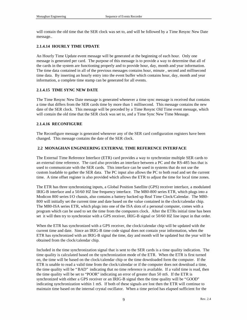
2.1.4.14 HOURLY TIME UPDATE
An Hourly Time Update event message will be generated at the beginning of each hour. Only onemessage is generated per card. The purpose of this message is to provide a way to determine that all ofthe cards in the system are functioning properly and to provide hour, day, month and year information.The time data contained in all of the previous messages contains hour, minute , second and millisecondtime data. By inserting an hourly entry into the event buffer which contains hour, day, month and yearinformation, a complete time stamp can be generated for all events.
2.1.4.15 TIME SYNC NEW DATE
The Time Resync New Date message is generated whenever a time sync message is received that containsa time that differs from the SER cards time by more than 1 millisecond. This message contains the newdate of the SER clock. This message will be preceded by a Time Resync Old Time event message, whichwill contain the old time that the SER clock was set to, and a Time Sync New Time Message.
2.1.4.16 RECONFIGURE
The Reconfigure message is generated whenever any of the SER card configuration registers have beenchanged. This message contains the date of the SER clock.
2.2 MONAGHAN ENGINEERING EXTERNAL TIME REFERENCE INTERFACE
The External Time Reference Interface (ETR) card provides a way to synchronize multiple SER cards toan external time reference. The card also provides an interface between a PC and the RS-485 bus that isused to communicate with the SER cards. This interface can be used in systems that do not use thecustom loadable to gather the SER data. The PC input also allows the PC to both read and set the currenttime. A time offset register is also provided which allows the ETR to adjust the time for local time zones.
The ETR has three synchronizing inputs, a Global Position Satellite (GPS) receiver interface, a modulatedIRIG-B interface and a 50/60 HZ line frequency interface. The M80-800 series ETR, which plugs into aModicon 800 series I/O chassis, also contains a battery backed up Real Time Clock/Calendar. The M80-800 will initially set the current time and date based on the value contained in the clock/calendar chip.The M80-ISA series ETR, which plugs into one of the ISA slots of a personal computer, comes with aprogram which can be used to set the time from the computers clock. After the ETRs initial time has beenset it will then try to synchronize with a GPS receiver, IRIG-B signal or 50/60 HZ line input in that order.
When the ETR has synchronized with a GPS receiver, the clock/calendar chip will be updated with thecurrent time and date. Since an IRIG-B time code signal does not contain year information, when theETR has synchronized with an IRIG-B signal the time, day and month will be updated but the year will beobtained from the clock/calendar chip.
Included in the time synchronization signal that is sent to the SER cards is a time quality indication. Thetime quality is calculated based on the synchronization mode of the ETR. When the ETR is first turnedon, the time will be based on the clock/calendar chip or the time downloaded form the computer. If theETR is unable to read a valid time from the clock/calendar or if the computer does not download a time,the time quality will be “BAD” indicating that no time reference is available. If a valid time is read, thenthe time quality will be set to “POOR” indicating an error of greater than 50 mS. If the ETR issynchronized with either a GPS receiver or an IRIG-B signal then the time quality will be “GOOD”indicating synchronization within 1 mS. If both of these signals are lost then the ETR will continue tomaintain time based on the internal crystal oscillator. When a time period has elapsed sufficient for the

Monaghan Engineering Sequence of Events Recorder
Rev. 2.410
crystal oscillator to have drifted more than 1 mS, the time quality will change to “FAIR” indicating anerror of greater than 1 mS but less than 50 mS. At this time the ETR will try to synchronize with the50/60 HZ input. If it can synchronize with the 50/60 HZ line input then the time quality will remain“FAIR” and the error will remain less than 50 mS. If no 50/60 HZ input is available, the ETR willcontinue to keep time based on the crystal oscillator. When a time period has elapsed sufficient for thecrystal oscillator to have drifted more than 50 mS, the time quality will change to “POOR indicating anerror of greater than 50 mS
2.2.1 ETR PROGRAMMING
The ETR is programmed by using the MODBUS Read Register and Preset Multiple Register commands.The ETR contains a block of registers starting at location 40001. If the custom loadable is used to gatherthe SER data, the only registers used are registers 40001 through 40010 which are defined as follows:
40001 - Month40002 - Day40003 - Year40004 - Hour40005 - Minute40006 - Second40007 - Millisecond40008 - Time quality. 0 = Good, 1 = Fair, 2 = Poor, 3 = Bad40009 - Time bias (+/- 23). Time which is added or subtracted from the GPS or IRIG-B time.40010 - Signal Source Bit 0 - GPS, Bit 1 - IRIG-B, Bit 2 - 50/60 Hz
If the custom loadable is not used to gather the SER data, the ETR can be programmed to perform thisfunction. When operating in this mode, the SER cards are configured as B807 modules and all timesynchronization, configuration and SER data gathering is done using the RS-485 port on each card.Appendix D contains a complete definition of all of the registers that are used to control the SER cards.
The registers are divided into groups according to their function. The first group of registers, 40021 -40085, contain the current state of each SER point.
The second group of registers, 40101 - 40191, contain the Event Buffer. The first register, 40101,contains the number of events in the buffer. The following registers contain up to 30 event records, witheach record occupying three registers.
The third group of registers, 40201 - 40291, contain the Event Resend Buffer. When a Modbuscommand to read the event buffer is received, the ETR will transmit the contents of the buffer to theModbus master device, copy the Event Buffer to the Event Resend Buffer and then clear the Event Buffer.By reading the Event Resend Buffer the Modus master can always retrieve the last Event Buffer that wasread.
The forth group of registers, 40301 - 40332, contain the card configuration data. Bit 0 of each register isused to define the scan status of each card. If the bit is set to 0, the card will not be configured or scannedby the ETR. If the bit is set to 1, the card will be configured and scanned by the ETR.
The fifth group of registers, 40351 - 40382, contain the card status data. Bits 0 and 1 are used to definethe communications status of the card. If both bits are set to 0, the card is communicating normally. Ifbit 0 is set to 1 and bit 1 is set to 0, communications with the card are marginal. If bit 0 is set to 0 and bit1 is set to 1, the card is not responding to communications requests.

Monaghan Engineering Sequence of Events Recorder
Rev. 2.411
The sixth group of registers, 40401 - 43596, contain point configuration data for each card. When any ofthe configuration registers for a card are changed, the ETR will download all 96 configuration registers tothe card.
2.2.2 ISA EXTERNAL TIME REFERENCE INTERFACE
The ISA External Time Reference Interface card plugs into an ISA slot of a PC. The card communicateswith the PC through a 1K block of shared memory. The shared memory can be assigned a startingaddress on any 1K boundary in the range of C0000 to FFC00. The card supports interrupt drivencommunications on IRQ lines 2,3,4,5 and 7. Commands are sent to the ETR by writing to a buffer andthen setting a semaphore register. This generates an interrupt in the ETR which will process thecommand. The ETR responds by writing to the proper buffer and then setting a semaphore register. If aninterrupt has been selected for the card, this will generate an interrupt to the PC. If interrupts have notbeen selected then the PC will have to poll the semaphore register to determine when it has been set.
The memory block is divided into three data buffer areas. The first buffer area, the transmit buffer, iscontained in memory locations 0 - 255. The PC communicates with the ETR by placing a Modbuscommand in the transmit buffer and then setting memory location 1022 equal to 1. The ETR will then setmemory location equal to 0 when the command is read.
The second buffer area, the receive buffer, is contained in memory locations 256 - 511. The ETRcommunicates with the PC by placing a Modbus response in the receive buffer and setting memorylocation 1023 equal to 1. The PC should then set memory location equal to 0 after the response is read.
The third buffer area, the time buffer, is contained in memory locations 512 - 520. This buffer is a readonly buffer which contains the contains of registers 40001 - 40009.
2.2.2.1 ISA SWITCH SETTINGS
The shared memory address for the ETR-ISA card is determined by the setting of switch S1.
A17 A16 A15 A14 A13 A12 A11 A10 Address
0 0 0 0 0 0 0 0 C0000 0 0 0 0 0 0 0 1 C0400 0 0 0 0 0 0 1 0 C0800 0 0 0 0 0 0 1 1 C0C00 0 0 0 0 0 1 0 0 C1000
.
.
. 1 1 1 1 1 1 1 0 FF800 1 1 1 1 1 1 1 1 FFC00
Switch Up - 1Switch Down - 0
2.2.2.2 ISA SOFTWARE
The ETR-ISA card is shipped with a windows based program which allows the personal computer tocommunicate with the card. The program displays the following main screen when it is running.

Monaghan Engineering Sequence of Events Recorder
Rev. 2.412
The current time, time quality and time code signal source is shown on the screen.
A good time quality is indicated by a green bar, a fair or poor time quality is indicated by a yellow bar,and a bad time quality is indicated by a red bar beside the appropriate label.
The signal source indicators are color coded to indicate the current condition of the signal. A green barindicates that the signal is currently being used as the time source. A yellow bar indicates that the signalis good but it is not being used as the timing source. A red bar indicates that the signal is present but notime code information is available, such as a GPS receiver connected and operating but not receiving asatellite signal.
The program setup may be changed by clicking on the Options selection and then clicking on the Setupselection.
Three clock options are provided. The program will set the PC clock when it is started, or the PC clockcan be set periodically, or the ETR clock can be set by the PC at startup.
If the option is selected which sets the PC clock periodically, the interval at which the clock is reset can beselected.
The time bias is the number of hours that are added or subtracted from the time code signal to generatethe correct time. This can be used to offset the time for Daylight Savings Time of to offset the time to theproper time zone.

Monaghan Engineering Sequence of Events Recorder
Rev. 2.413
The ETR Base Address setting is used to define the selected base address of the ETR card.
When a Trimble Navigation Acutime receiver is connected to the ETR, the GPS receiver statusinformation is available click on the Options selection and then clicking on the GPS Data selection.
The current status of the GPS receiver is displayed at the top. The normal status is “Doing position fixes”.All other status conditions indicate an error, and the time displayed may be in error.
The time of week is the number of seconds since midnight the previous Sunday. The UTC offset is thedifference between GPS time, the time provided by the satellite, and UTC, Universal Coordinated Time.UTC = (GPS time) -(UTC offset)
2.2.3 800 SERIES EXTERNAL TIME REFERENCE INTERFACE
The 800 Series External Time Reference Interface card plugs into the I/O slot of an 800 Series I/Ochassis. The card communicates with a PC through an RS-232 interface on the card. Allcommunications with the card are through Modbus messages.
2.2.4 IRIG-B INTERFACE
The IRIG-B interface provides an industry standard time code interface. The connection is through aBNC connector on the interface card. The IRIG-B decoder is designed for a modulated IRIG-B signal.
2.2.5 TRIMBLE ACUTIME INTERFACE
The Acutime receiver, manufactured by Trimble Navigation, is a low cost GPS satellite receiver. Theinterface consists of an RS-422 interface which is used to interrogate the Acutime receiver for the currenttime and an interface for the one pulse per second output from the Acutime receiver which is used todetermine the start of each second.
2.3 NOVATECH BM85E/PC
A BM85E or a PC may be used as a data concentrator in the field to receive and process SOE events fromdifferent PLCs via Modbus Plus. Depending on the application, the BM85E or PC may perform a varietyof tasks:
• sort events according to time stamps, type of event, or originating PLC• print events on on-site printer and/or terminal• forward events via leased line, dialup modem and telephone line, or radio to a remote engineering PC
for data processing and storage

Monaghan Engineering Sequence of Events Recorder
Rev. 2.414
• provide protocol conversion for bit oriented protocol or byte oriented protocol in order to allow an on-line connection to a SCADA master (BM85E only)
• store SOE data on hard drive (PC only)• notification of technical personnel via pagers and alphanumeric event codes in case of emergencies by
using a modem

Monaghan Engineering Sequence of Events Recorder
Rev. 2.415
3.0 SER SOFTWARE
3.1 SER LOADABLE
The SER software performs three separate functions. Each of these functions is implemented in a separateloadable.
For every SER module mounted with a PLC, one instance of the SER Card function block in ladder logicis required. The purpose of this kind of function block is to upload SOE events from the SER moduleto which it is assigned, and store the events in a SOE event buffer in the PLC.
The SER Modbus Plus loadable sends the events uploaded by all SER Card function blocks in the PLC, toa BM85E or a PC with a SA85 card. It is used only once throughout the entire ladder logic.
The SER Clock (CLCK) loadable is optional. It is also used only once in the entire ladder logic. Itspurpose is to set the PLC's time of day clock (if configured) to the IRIG-B time received from a SER card.However, should the SER card be unable to receive the IRIG-B time, or operated without IRIG-B input,the loadable allows the ladder logic program to set the SER card's clock with the PLC's time of day clock.
3.1.1 PLC CONFIGURATION
The SER Input Module M884 is configured as a B884 in the PLC's I/O map. For every SER inputmodule, there must be one entry in the I/O map. Other I/O modules may be configured as needed.
The following example shows the I/O map for three SER input modules.
Utility DelDrop HoldTme ASCPort GetDrop QuitF1-------F2-------F3-------F4-------F5-------F6-------F7-Lev 8-F8-OFF---F9-----+¦ ¦¦ I/O MAP ¦¦ 800 SERIES I/O ¦¦ Drop : 1 of 1 Rack : 1 ¦¦ Drop Hold Up Time : 3 (x100ms) ASCII Port : 0 ¦¦ Number Inputs : 192 Number Outputs : 192 ¦¦ ---------------------------------------------------------------------- ¦¦ Module Reference Numbers Data Module ¦¦ Slot Type Input Output type Description ¦¦ ¦¦ 101 984 PLC-685 ¦¦ 102 984 PLC-685 ¦¦ 103 B884 10001 -10064 00001 -00064 BIN BIDIR 4 REG B884 ¦¦ 104 B884 10065 -10128 00065 -00128 BIN BIDIR 4 REG B884 ¦¦ 105 B884 10129 -10192 00129 -00192 BIN BIDIR 4 REG B884 ¦¦ 106 B8 ¦¦ 107 B8 ¦¦ 108 B8 ¦¦ 109 B8 ¦¦ 110 B8 ¦¦ 111 B8 ¦¦ ¦+------------------------------------------------------------------------------+
The SER Loadable is loaded into a PLC configuration with the following sequence of key strokes:
1. Select the PLC configuration2. Press <F7> (Loadable) in order to select the screen shown below.3. Press <F3> (Directory)4. Press <F1> (Load). Modsoft pops up a window in which the DOS file name must be entered. If, for
example, the loadable file CARD.DAT is stored in the directory
Monaghan Engineering Sequence of Events Recorder
Rev. 2.416
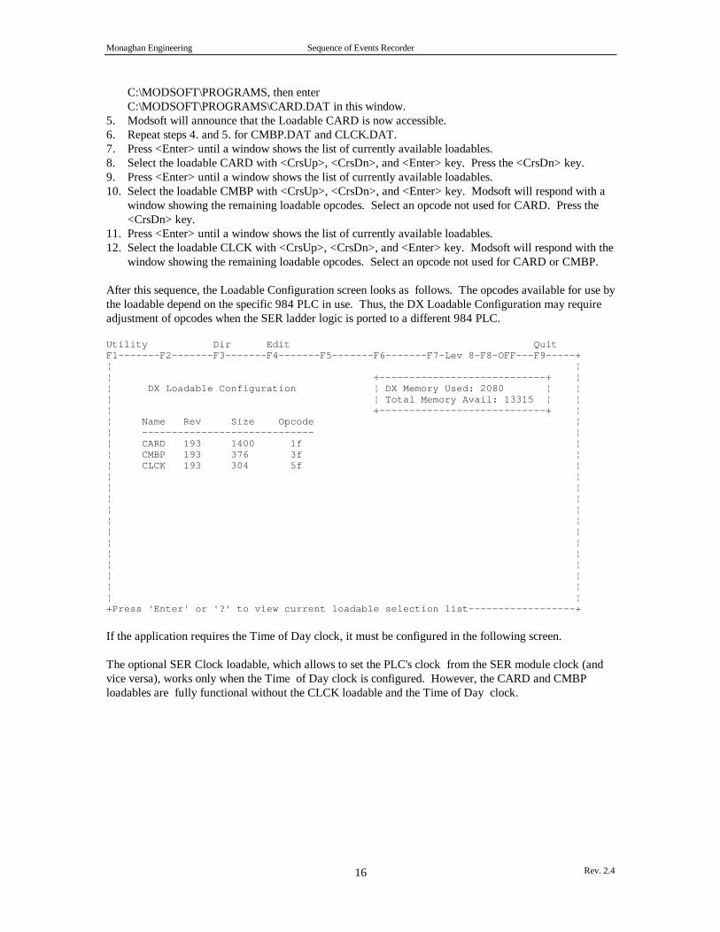
C:\MODSOFT\PROGRAMS, then enterC:\MODSOFT\PROGRAMS\CARD.DAT in this window.
5. Modsoft will announce that the Loadable CARD is now accessible.6. Repeat steps 4. and 5. for CMBP.DAT and CLCK.DAT.7. Press <Enter> until a window shows the list of currently available loadables.8. Select the loadable CARD with <CrsUp>, <CrsDn>, and <Enter> key. Press the <CrsDn> key.9. Press <Enter> until a window shows the list of currently available loadables.10. Select the loadable CMBP with <CrsUp>, <CrsDn>, and <Enter> key. Modsoft will respond with a
window showing the remaining loadable opcodes. Select an opcode not used for CARD. Press the<CrsDn> key.
11. Press <Enter> until a window shows the list of currently available loadables.12. Select the loadable CLCK with <CrsUp>, <CrsDn>, and <Enter> key. Modsoft will respond with the
window showing the remaining loadable opcodes. Select an opcode not used for CARD or CMBP.
After this sequence, the Loadable Configuration screen looks as follows. The opcodes available for use bythe loadable depend on the specific 984 PLC in use. Thus, the DX Loadable Configuration may requireadjustment of opcodes when the SER ladder logic is ported to a different 984 PLC.
Utility Dir Edit QuitF1-------F2-------F3-------F4-------F5-------F6-------F7-Lev 8-F8-OFF---F9-----+¦ ¦¦ +----------------------------+ ¦¦ DX Loadable Configuration ¦ DX Memory Used: 2080 ¦ ¦¦ ¦ Total Memory Avail: 13315 ¦ ¦¦ +----------------------------+ ¦¦ Name Rev Size Opcode ¦¦ ----------------------------- ¦¦ CARD 193 1400 1f ¦¦ CMBP 193 376 3f ¦¦ CLCK 193 304 5f ¦¦ ¦¦ ¦¦ ¦¦ ¦¦ ¦¦ ¦¦ ¦¦ ¦¦ ¦¦ ¦¦ ¦¦ ¦+Press 'Enter' or '?' to view current loadable selection list------------------+
If the application requires the Time of Day clock, it must be configured in the following screen.
The optional SER Clock loadable, which allows to set the PLC's clock from the SER module clock (andvice versa), works only when the Time of Day clock is configured. However, the CARD and CMBPloadables are fully functional without the CLCK loadable and the Time of Day clock.

Monaghan Engineering Sequence of Events Recorder
Rev. 2.417
Utility OverView I/OMap Ports Segmnts Loadable Cfg Ext QuitF1-------F2-------F3-------F4-------F5-------F6-------F7-Lev 8-F8-OFF---F9-----+¦ CONFIGURATION OVERVIEW ¦¦ ¦ Size of Full Logic Area 13867 ¦¦ PLC : ¦ No. of I/O Map Words 00015 ¦¦ PLC Type 984 - 685 +---------------------------------- ¦¦ Exec Pack 914 ¦ I/O : I/O Type 800 ¦¦ Memory 16.0K ¦ Number of Segments 32 ¦¦ Extended Memory K ¦ IO Drops / Channel Pairs 1 ¦¦ Redundant N ¦ I/O Modules 1 ¦¦ DCP Drop ID +---------------------------------- ¦¦ ------------------------------¦ Specials : ¦¦ ¦ Battery Coil 0----- ¦¦ Ranges : ¦ Timer Register 4----- ¦¦ 0xxxx 00001 - 01536 ¦>>Time of Day Clock 41500 - 41507<<¦¦ 1xxxx 10001 - 10512 ¦ ¦¦ 3xxxx 30001 - 30048 +----------------------------------- ¦¦ 4xxxx 40001 - 41872 ¦ ASCII: ¦¦ 4xxxx for SFC None ¦ Number of Messages 0 ¦¦ ¦ Message Area Size 0 ¦¦ ------------------------------¦ Number of ASCII Ports 0 ¦¦ 0xxxx for SFC None ¦ Simple ASCII Output ¦¦ ¦ Simple ASCII Input ¦¦ ¦+I/O Map is the traffic cop which links the I/O modules to program logic. +
3.1.2 LADDER LOGIC PROGRAM
The various function blocks are used in ladder logic as follows.
Loadable Name Function DescriptionCARD SER Card
LoadableUploads the SOE events from a specific SER module to a commonbuffer used by all SER modules, in the PLC's 4x registers.
CMBP SER ModbusPlus Loadable
Controls an MSTR function block which sends the SOE events fromthe PLC's SOE event buffer to a BM85 or a PC with a SA85 card.
CLCK SER ClockLoadable
Allows to set PLC's Time of Day clock with IRIG-B time from SERmodule, and vice versa if necessary. The use of this loadable isoptional.

Monaghan Engineering Sequence of Events Recorder
Rev. 2.418
Utility PlcOps Elements Edit Go/Srch Network Refs Tools QuitF1-------F2-------F3-------F4-------F5-------F6-------F7-Lev 8-F8-COMBO-F9-R4--+¦Seg. 1 #1 /1 SER MB+ Function incl. MSTR ¦¦+ +--------------------- ¦¦¦ ¦ 40014¦ ¦¦+ ¦ ¦ +---( )-- ¦¦¦ ¦ 40023¦¦01500 ¦¦+ ¦ ¦MSTR++ ¦¦¦ ¦ #0100+ ¦¦+--------------------+ ¦¦¦ #0001¦ ¦¦+--¦P+--¦ +---( )-- ¦¦¦01500 40001¦ 00001 ¦¦+--¦ +--¦CMBP+---( )-- ¦¦¦01501 #0122+ 00002 ¦¦+ ¦¦¦ ¦+------------------------------------------------------------------------------++------------------------------ Reference Data --------------------------------+¦01500 MSTRFeedBk 0 E ¦ 40001 SERSendBlk 500 Dec ¦¦01501 FlushQueue 0 E ¦ ¦¦ ¦ 40014 MSTR_Setup 1 Dec ¦¦00001 FillQueue 1 E ¦ 40023 EventBuf 2 Dec ¦¦00002 SER_Error 0 E ¦ ¦+ Format :Decimal Online Range : 1 --------------------------------+
Utility PlcOps Elements Edit Go/Srch Network Refs Tools QuitF1-------F2-------F3-------F4-------F5-------F6-------F7-Lev 8-F8-COMBO-F9-R4--+¦Seg. 1 #2 /2 SER Cards 1 and 2 ¦¦+-------------- ¦¦¦ #0001¦ ¦¦+--¦P+--¦ +---( )-- ¦¦¦00008 40400¦ 00009 ¦¦+--¦ +--¦CARD+---( )-- ¦¦¦00001 #0130+ 00010 ¦¦+ ¦¦¦ ¦¦+-------------- ¦¦¦ #0002¦ ¦¦+--¦P+--¦ +---( )-- ¦¦¦00011 40700¦ 00012 ¦¦+--¦ +--¦CARD+---( )-- ¦¦¦00001 #0130+ 00013 ¦+------------------------------------------------------------------------------++------------------------------ Reference Data --------------------------------+¦00001 FillQueue 1 E ¦ ¦¦00008 ConfgCard1 0 E ¦ 00011 ConfgCard2 0 E ¦¦00009 Cnfg1Compl 0 E ¦ 00012 Cnfg2Compl 0 E ¦¦00010 SERCrd1Err 0 E ¦ 00013 SERCrd2Err 0 E ¦¦40400 SERCrd1Blk 10 Dec ¦ 40700 SERCrd2Blk 0 Dec ¦+ Format :Decimal Online Range : 1 --------------------------------+
Monaghan Engineering Sequence of Events Recorder
Rev. 2.419
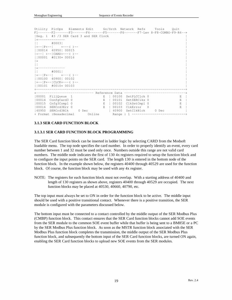
Utility PlcOps Elements Edit Go/Srch Network Refs Tools QuitF1-------F2-------F3-------F4-------F5-------F6-------F7-Lev 8-F8-COMBO-F9-R4--+¦Seg. 1 #3 /3 SER Card 3 and SER Clock ¦¦+-------------- ¦¦¦ #0003¦ ¦¦+--¦P+--¦ +---( )-- ¦¦¦00014 40950¦ 00015 ¦¦+--¦ +--¦CARD+---( )-- ¦¦¦00001 #0130+ 00016 ¦¦+ ¦¦¦ ¦¦+-------------- ¦¦¦ #0001¦ ¦¦+--¦P+--¦ +---( )-- ¦¦¦00100 40900¦ 00102 ¦¦+--¦P+--¦CLCK+---( )-- ¦¦¦00101 #0010+ 00103 ¦+------------------------------------------------------------------------------++------------------------------ Reference Data --------------------------------+¦00001 FillQueue 1 E ¦ 00100 SetPLCClck 0 E ¦¦00014 ConfgCard3 0 E ¦ 00101 SetSERClks 0 E ¦¦00015 Cnfg3Compl 0 E ¦ 00102 ClkSetCmpl 0 E ¦¦00016 SERCrd3Err 0 E ¦ 00103 ClkError 0 E ¦¦40950 SERCrd3Blk 0 Dec ¦ 40900 SetClkBlck 0 Dec ¦+ Format :Hexadecimal Online Range : 1 ----------------------------+
3.1.3 SER CARD FUNCTION BLOCK
3.1.3.1 SER CARD FUNCTION BLOCK PROGRAMMING
The SER Card function block can be inserted in ladder logic by selecting CARD from the Modsoftloadable menu. The top node specifies the card number. In order to properly identify an event, every cardnumber between 1 and 32 must be used only once. Numbers outside this range are not valid cardnumbers. The middle node indicates the first of 130 4x registers required to setup the function block andto configure the input points on the SER card. The length 130 is entered in the bottom node of thefunction block. In the example shown below, the registers 40400 through 40529 are used for the functionblock. Of course, the function block may be used with any 4x register.
NOTE: The registers for each function block must not overlap. With a starting address of 40400 andlength of 130 registers as shown above, registers 40400 through 40529 are occupied. The nextfunction blocks may be placed at 40530, 40660, 40790, etc.
The top input must always be set to ON in order for the function block to be active. The middle inputshould be used with a positive transitional contact. Whenever there is a positive transition, the SERmodule is configured with the parameters discussed below.
The bottom input must be connected to a contact controlled by the middle output of the SER Modbus Plus(CMBP) function block. This contact ensures that the SER Card function blocks cannot add SOE eventsfrom the SER module to the common SOE event buffer while that buffer is being sent to a BM85E or a PCby the SER Modbus Plus function block. As soon as the MSTR function block associated with the SERModbus Plus function block completes the transmission, the middle output of the SER Modbus Plusfunction block, and subsequently the bottom input of the SER Card function blocks, are turned ON again,enabling the SER Card function blocks to upload new SOE events from the SER modules.

Monaghan Engineering Sequence of Events Recorder
Rev. 2.420
ON = Activate -------------- Echoes Top Input Function Block ¦#1 ¦ ¦ ¦ --¦P+------¦ +-- ON (One Scan) = 0->1 = Configure ¦40400 ¦ Configuration SER Module ¦ ¦ Completed ON = Fill --¦CARD +-- ON = Setup Error Event Queue ¦#130 ¦ +--------+
The top output echoes the top input of the function block.
The middle output is set to ON for one scan after the middle input has been triggered for configuration ofthe SER module, and the configuration has completed.
The bottom output is turned ON for illegal function block setup parameters.
3.1.3.2 SER CARD FUNCTION BLOCK PARAMETERS
The SER Card parameters can be entered using the Modsoft reference editor or Novatech's template.These parameters can also be changed as needed by the ladder logic program during its execution. Pleasenote that the addresses for the parameters are relative to the register address in the middle node of thefunction block as shown above.The following template pages can be invoked in Modsoft using the key combination <Alt>-Z when theladder logic cursor is placed on the SER Card function block.
Utility Hex Dec Bin Goto QuitF1-------F2-------F3-------F4-- DX Zoom Editor -------F7-Lev 8-F8-OFF---F9-----+¦ Page 1 / 14¦¦ SER Module Setup V1.01 by NovaTech, Inc. (C) 1995 ¦¦ ------------------------------------------------- ¦¦ ¦¦ CARD FUNCTION BLOCK-I/O MAP LINK ¦¦ SER Card's First 1x Addr. in I/O Map [xxxx] 40497 INT = 1400 DEC ¦¦ SER Card's First 0x Addr. in I/O Map [xxxx] 40498 INT = 209 DEC ¦¦ ¦¦ CARD FUNCTION BLOCK-CMBP FUNCTION BLOCK LINK ¦¦ Register in Middle Node of CMBP Loadable 40499 INT = 1 DEC ¦¦ ¦¦ ¦¦ INPUT POINT PARAMETERIZATION ¦¦ First Point to be Parameterized (1-32) 40501 INT = 7 DEC ¦¦ Last Point to be Parameterized (1-32) 40502 INT = 7 DEC ¦¦ Parameterize 0=All Points Individually 40503 INT = 1 ¦¦ 1=Copy Point #1 Parameters ¦¦ Re-parameterize Points on Power Reset 0=No 40504 INT = 1 ¦¦ 1=Yes ¦¦ ¦¦ ¦¦ ¦+------------------------------------------------------------------------------+
Address of First 1x Input in I/O Map Range: depends on number of 1x inputs in PLC configuration Offset: +97 Usage: The SER Card function block must read the values from the SER module through 1x inputs. In
this case, the 1x inputs used by the SER module are 10001 through 10064. Please note that theaddress entered here must match a 1x address as entered in the PLC's I/O map for the SERmodule. The first 32 inputs, in this case 10001 through 10032, are used to report the status ofeach of the 32 status inputs. 10033 through 10064 are used for internal purposes.
Note: This value must vary for all SER Card function blocks, and must not be changed by ladder logic.
Monaghan Engineering Sequence of Events Recorder
Rev. 2.421
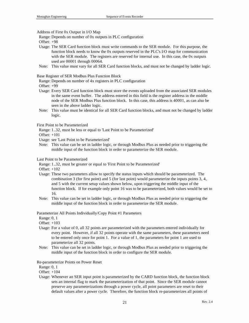
Address of First 0x Output in I/O Map Range: Depends on number of 0x outputs in PLC configuration Offset: +98 Usage: The SER Card function block must write commands to the SER module. For this purpose, the
function block needs to know the 0x outputs reserved in the PLC's I/O map for communicationwith the SER module. The registers are reserved for internal use. In this case, the 0x outputsused are 00001 through 00064.
Note: This value must vary for all SER Card function blocks, and must not be changed by ladder logic.
Base Register of SER Modbus Plus Function Block Range: Depends on number of 4x registers in PLC configuration Offset: +99 Usage: Every SER Card function block must store the events uploaded from the associated SER modules
in the same event buffer. The address entered in this field is the register address in the middlenode of the SER Modbus Plus function block. In this case, this address is 40001, as can also beseen in the above ladder logic.
Note: This value must be identical for all SER Card function blocks, and must not be changed by ladderlogic.
First Point to be Parameterized Range: 1..32, must be less or equal to 'Last Point to be Parameterized' Offset: +101 Usage: see 'Last Point to be Parameterized' Note: This value can be set in ladder logic, or through Modbus Plus as needed prior to triggering the
middle input of the function block in order to parameterize the SER module.
Last Point to be Parameterized Range: 1..32, must be greater or equal to 'First Point to be Parameterized' Offset: +102 Usage: These two parameters allow to specify the status inputs which should be parameterized. The
combination 3 (for first point) and 5 (for last point) would parameterize the inputs points 3, 4,and 5 with the current setup values shown below, upon triggering the middle input of thefunction block. If for example only point 16 was to be parameterized, both values would be set to16.
Note: This value can be set in ladder logic, or through Modbus Plus as needed prior to triggering themiddle input of the function block in order to parameterize the SER module.
Parameterize All Points Individually/Copy Point #1 Parameters Range: 0, 1 Offset: +103 Usage: For a value of 0, all 32 points are parameterized with the parameters entered individually for
every point. However, if all 32 points operate with the same parameters, these parameters needto be entered only once for point 1. For a value of 1, the parameters for point 1 are used toparameterize all 32 points.
Note: This value can be set in ladder logic, or through Modbus Plus as needed prior to triggering themiddle input of the function block in order to configure the SER module.
Re-parameterize Points on Power Reset Range: 0, 1 Offset: +104 Usage: Whenever an SER input point is parameterized by the CARD function block, the function block
sets an internal flag to mark the parameterization of that point. Since the SER module cannotpreserve any parameterizations through a power cycle, all point parameters are reset to theirdefault values after a power cycle. Therefore, the function block re-parameterizes all points of

Monaghan Engineering Sequence of Events Recorder
Rev. 2.422
the SER cards which have been parameterized before, as indicated by the internal flags, if thisregister is set to 1. If re-parameterization is not desired, this register must be set to 0. In thiscase, all SER card input points use their default parameters after a power cycle. In addition, theinternal flag marking previous parameterization, is reset.
Note: This value can be set in ladder logic, or through Modbus Plus. The value will affect pointparameterization only when the Power On Reset event is received from the SER card. Whenevera point is re-parameterized, the parameters currently stored in the three parameter registersassociated with that point are used.
All 32 points can be configured individually with a template as follows. These values can also be changedin ladder logic or through Modbus Plus, depending on a specific application.
Utility Hex Dec Bin Goto QuitF1-------F2-------F3-------F4-- DX Zoom Editor -------F7-Lev 8-F8-OFF---F9-----+¦ Page 2 / 14¦¦ SER Module Setup V1.01 by NovaTech, Inc. (C) 1995 ¦¦ ------------------------------------------------ ¦¦ DIGITAL INPUT #1 ¦¦ Contact Filter Time (0-65535ms) 40400 INT = 10 DEC ¦¦ Contact Debounce Time (0-65535ms) 40401 INT = 20 DEC ¦¦ Chatter Count (0-255) 40402 01:08 = 4 DEC ¦¦ Scan Status (0-On 1-Off) 40402 BIT16 = 0 ¦¦ ¦¦ DIGITAL INPUT #2 ¦¦ Contact Filter Time (0-65535ms) 40403 INT = 4000 DEC ¦¦ Contact Debounce Time (0-65535ms) 40404 INT = 5000 DEC ¦¦ Chatter Count (0-255) 40405 01:08 = 6 DEC ¦¦ Scan Status (0-On 1-Off) 40405 BIT16 = 0 ¦¦ ¦¦ DIGITAL INPUT #3 ¦¦ Contact Filter Time (0-65535ms) 40406 INT = 10 DEC ¦¦ Contact Debounce Time (0-65535ms) 40407 INT = 20 DEC ¦¦ Chatter Count (0-255) 40408 01:08 = 10 DEC ¦¦ Scan Status (0-On 1-Off) 40408 BIT16 = 0 ¦¦ ¦¦ ¦+------------------------------------------------------------------------------+
The following set of parameters can be entered for all 32 points.
Contact Filter Time Range: 0..65535 Offset: +0, +3, +6, +9, +12, ... Default: 20 ms Usage: The purpose of the contact filter time is to eliminate false event messages caused by noise. The
filter time is the amount of time that a point must stay in a new state in order to be recognized asan event. As an example, if the filter time for a point is set to 25 milliseconds, then when theinput changes state it must remain in the new state for 25 milliseconds before and event messageis generated. If the input returns to the previous state in less than 25 milliseconds, the filter isreset and the next time the state changes it will again have to remain in that state for 25milliseconds before an event message is generated. The time that is associated with the event isthe time at which the point first changed, not the time when the filter recognized the event. Iftwo input points that different input filter values were to change at the same time, the eventmessages would be generated at different times but the time that was contained in the eventmessage would be identical.
Note: This value can be set in ladder logic, or through Modbus Plus as needed prior to triggering themiddle input of the function block in order to configure the SER module.
Contact Debounce Time

Monaghan Engineering Sequence of Events Recorder
Rev. 2.423
Range: 0..65535 Offset: +1, +4, +7, +10, +13, ... Default: 10 ms Usage: The purpose of the contact debounce time is to prevent multiple events from being generated
from a single contact closure. The debounce time is the amount of time that input processing isdisabled for a point after an event has been recorded
Note: This value can be set in ladder logic, or through Modbus Plus as needed prior to triggering themiddle input of the function block in order to configure the SER module.
Chatter Count Range: 0..255 Offset: 8 MSB bits of +2, +5, +8, +11, +14, ... Default: 10 Usage: This parameter determines the maximum number of status changes allowed per minute before
the point is taken off scan. Once a point is taken off scan, it will be put on scan again after beingat least one minute below the chatter count.Examples: Point A is taken off scan at 07:14:52.253
--> Point A goes back on scan at 07:16:00.000Point B is taken off scan at 07:14:05.745--> Point B goes back on scan at 07:16:00.000
Note: This value can be set in ladder logic, or through Modbus Plus as needed prior to triggering themiddle input of the function block in order to configure the SER module.
Scan Status Range: 0, 1 Offset: LSB bit of +2, +5, +8, +11, +14, ... Default:0 (on scan) Usage: A point can be taken off scan manually for maintenance and testing by setting the scan status to 1
(off scan), and then reconfiguring that point or set of points. Note: This value can be set in ladder logic, or through Modbus Plus as needed prior to triggering the
middle input of the function block in order to configure the SER module.
The following template page shows the function block status. It is to be used for read-only.
Monaghan Engineering Sequence of Events Recorder
Rev. 2.424
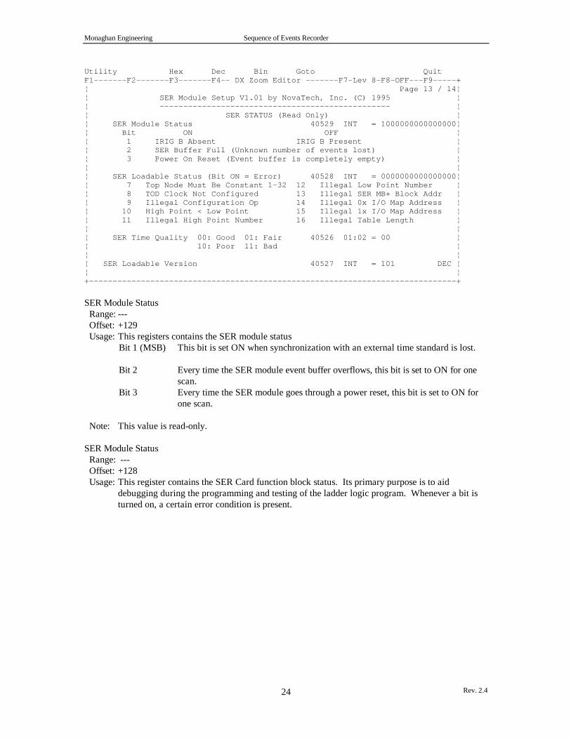
Utility Hex Dec Bin Goto QuitF1-------F2-------F3-------F4-- DX Zoom Editor -------F7-Lev 8-F8-OFF---F9-----+¦ Page 13 / 14¦¦ SER Module Setup V1.01 by NovaTech, Inc. (C) 1995 ¦¦ ------------------------------------------------- ¦¦ SER STATUS (Read Only) ¦¦ SER Module Status 40529 INT = 1000000000000000¦¦ Bit ON OFF ¦¦ 1 IRIG B Absent IRIG B Present ¦¦ 2 SER Buffer Full (Unknown number of events lost) ¦¦ 3 Power On Reset (Event buffer is completely empty) ¦¦ ¦¦ SER Loadable Status (Bit ON = Error) 40528 INT = 0000000000000000¦¦ 7 Top Node Must Be Constant 1-32 12 Illegal Low Point Number ¦¦ 8 TOD Clock Not Configured 13 Illegal SER MB+ Block Addr ¦¦ 9 Illegal Configuration Op 14 Illegal 0x I/O Map Address ¦¦ 10 High Point < Low Point 15 Illegal 1x I/O Map Address ¦¦ 11 Illegal High Point Number 16 Illegal Table Length ¦¦ ¦¦ SER Time Quality 00: Good 01: Fair 40526 01:02 = 00 ¦¦ 10: Poor 11: Bad ¦¦ ¦¦ SER Loadable Version 40527 INT = 101 DEC ¦¦ ¦+------------------------------------------------------------------------------+
SER Module Status Range: --- Offset: +129 Usage: This registers contains the SER module status
Bit 1 (MSB) This bit is set ON when synchronization with an external time standard is lost.
Bit 2 Every time the SER module event buffer overflows, this bit is set to ON for onescan.
Bit 3 Every time the SER module goes through a power reset, this bit is set to ON forone scan.
Note: This value is read-only.
SER Module Status Range: --- Offset: +128 Usage: This register contains the SER Card function block status. Its primary purpose is to aid
debugging during the programming and testing of the ladder logic program. Whenever a bit isturned on, a certain error condition is present.

Monaghan Engineering Sequence of Events Recorder
Rev. 2.425
Bit Error Condition16 (LSB) Table length in bottom node of function block must be set to 130.15 The 0x address entered in the function block is outside the valid 0x addresses as
configured in the PLC's configuration. For example, if the inputs 10001 through10512 are configured, the highest valid 1x address would be 10449, since theSER module requires 64 1x inputs.
14 The 0x address entered in the function block is outside the valid 0x addresses asconfigured in the PLC's configuration. For example, if the outputs 00001through 01536 are configured, the highest valid 0x address would be 01473, sincethe SER module requires 64 0x outputs.
13 The 4x address entered is not the base address in the middle node of the SERModbus Plus function block.
12 The number of the first point to be configured is out of range, i.e. less than 1 orgreater than 32.
11 The number of the last point to be configured is out of range, i.e. less than 1 orgreater than 32.
10 The number of the first point to be configured is greater than the number of thelast point to be configured.
9 The selected configuration operation must be 0 (configure all points individually)or 1 (configure all points with parameters from point 1). Other values are notallowed.
8 The Time of Day Clock must be configured. This error is set only when theCLCK loadable is used.
7 The top node of the function block must be a value between 1 and 32 in order toidentify the associated SER card. It must not be a 4x register.
Note: This value is read-only.
SER Time Quality Range: 00-11 in the two MSB bits Offset: +126 Usage: This register contains the current quality of the SER time stamps, in the two MSB bits. The
values are as follows:
Bit Quality1 2 3-160 0 x..x Good, accuracy is GMT +/- 1ms0 1 x..x Fair, accuracy is GMT +/- 50ms1 0 x..x Poor, accuracy is GMT +/- 50ms or worse1 1 x..x Bad, no time reference available
Note: This value is read-only.
3.1.4 SER MODBUS PLUS FUNCTION BLOCK
3.1.4.1 SER MODBUS PLUS FUNCTION BLOCK PROGRAMMING
The SER Modbus Plus function block can be inserted in ladder logic by selecting CMBP from the Modsoftloadable menu. The top node must always be set to #1. The middle node indicates the first of 122 4xregisters required to manage the common event buffer and to control the associated MSTR function block.The length 122 is entered in the bottom node of the function block. In the example shown below, theregisters 40001 through 40122 are used for the function block. Of course, the function block may be usedwith any 4x register.
Monaghan Engineering Sequence of Events Recorder
Rev. 2.426
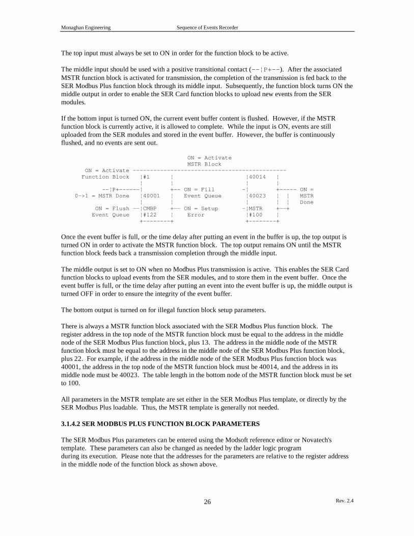
The top input must always be set to ON in order for the function block to be active.
The middle input should be used with a positive transitional contact (--¦P+--). After the associatedMSTR function block is activated for transmission, the completion of the transmission is fed back to theSER Modbus Plus function block through its middle input. Subsequently, the function block turns ON themiddle output in order to enable the SER Card function blocks to upload new events from the SERmodules.
If the bottom input is turned ON, the current event buffer content is flushed. However, if the MSTRfunction block is currently active, it is allowed to complete. While the input is ON, events are stilluploaded from the SER modules and stored in the event buffer. However, the buffer is continuouslyflushed, and no events are sent out.
ON = Activate MSTR Block ON = Activate --------------------------------------------- Function Block ¦#1 ¦ ¦40014 ¦ ¦ ¦ ¦ ¦ --¦P+------¦ +-- ON = Fill -¦ +----- ON = 0->1 = MSTR Done ¦40001 ¦ Event Queue ¦40023 ¦ ¦ MSTR ¦ ¦ ¦ ¦ ¦ Done ON = Flush --¦CMBP +-- ON = Setup -¦MSTR +--+ Event Queue ¦#122 ¦ Error ¦#100 ¦ +--------+ +--------+
Once the event buffer is full, or the time delay after putting an event in the buffer is up, the top output isturned ON in order to activate the MSTR function block. The top output remains ON until the MSTRfunction block feeds back a transmission completion through the middle input.
The middle output is set to ON when no Modbus Plus transmission is active. This enables the SER Cardfunction blocks to upload events from the SER modules, and to store them in the event buffer. Once theevent buffer is full, or the time delay after putting an event into the event buffer is up, the middle output isturned OFF in order to ensure the integrity of the event buffer.
The bottom output is turned on for illegal function block setup parameters.
There is always a MSTR function block associated with the SER Modbus Plus function block. Theregister address in the top node of the MSTR function block must be equal to the address in the middlenode of the SER Modbus Plus function block, plus 13. The address in the middle node of the MSTRfunction block must be equal to the address in the middle node of the SER Modbus Plus function block,plus 22. For example, if the address in the middle node of the SER Modbus Plus function block was40001, the address in the top node of the MSTR function block must be 40014, and the address in itsmiddle node must be 40023. The table length in the bottom node of the MSTR function block must be setto 100.
All parameters in the MSTR template are set either in the SER Modbus Plus template, or directly by theSER Modbus Plus loadable. Thus, the MSTR template is generally not needed.
3.1.4.2 SER MODBUS PLUS FUNCTION BLOCK PARAMETERS
The SER Modbus Plus parameters can be entered using the Modsoft reference editor or Novatech'stemplate. These parameters can also be changed as needed by the ladder logic programduring its execution. Please note that the addresses for the parameters are relative to the register addressin the middle node of the function block as shown above.

Monaghan Engineering Sequence of Events Recorder
Rev. 2.427
The following template pages can be invoked in Modsoft using the key combination <Alt>-Z when theladder logic cursor is placed on the SER Modbus Plus function block.
Utility Hex Dec Bin Goto QuitF1-------F2-------F3-------F4-- DX Zoom Editor -------F7-Lev 8-F8-OFF---F9-----+¦ Page 1 / 2¦¦ SER Modbus Plus V1.01 by NovaTech, Inc. (C) 1994 ¦¦ ----------------------------------------------- ¦¦ ¦¦ SER MODBUS PLUS SETUP ¦¦ PLC Identifier 40023 INT = 2 DEC ¦¦ Send Delay for First Event (0-6000) [10ms] 40001 INT = 500 DEC ¦¦ MSTR Retry Delay (0-6000) [10ms] 40002 INT = 500 DEC ¦¦ MSTR Routing Byte 1 (1-64) 40018 INT = 2 DEC ¦¦ MSTR Routing Byte 2 (1-64) 40019 INT = 1 DEC ¦¦ MSTR Routing Byte 3 (1-64) 40020 INT = 0 DEC ¦¦ MSTR Routing Byte 4 (1-64) 40021 INT = 0 DEC ¦¦ MSTR Routing Byte 5 (1-64) 40022 INT = 0 DEC ¦¦ ¦¦ SER MODBUS PLUS RESULTS (Read Only) ¦¦ Number of Events in Queue 40025 INT = 0 DEC ¦¦ SER Event Forwarder Status 40010 INT = 0000000000000000¦¦ MSTR Status 40015 INT = 0000 HEX ¦¦ ¦¦ ¦¦ SER Loadable Version 40032 INT = 100 DEC ¦¦ ¦+------------------------------------------------------------------------------+
PLC Identifier Range: 0..32767 Offset: +22 Usage: Any input point must be identified by PLC in addition to SER module number and the actual
point number in order to ensure proper system-wide identification. In case, all events are taggedas events from PLC 2, regardless of the SER module within PLC 2.
Note: This value must be unique for all PLCs in the SER system in order to properly identify SOEevents, and should not be changed by ladder logic.
Send Delay for First Event [10ms] Range: 0..6000 (0..60 seconds) Offset: +0 Usage: When an event is placed in the event buffer, its forwarding to the BM85E or PC is delayed by
this delay factor, whose unit is 10ms. For example a value of 500 indicates a delay of 5 seconds.If within 5 seconds another event is placed in the event buffer, the delay timer is reset. However,the current event buffer is sent when (a) the delay time is up, and no additional event has beenplaced in the event buffer, or (b) the delay time is not up yet, but the event buffer has been filledentirely, i.e. there are 30 events in the event buffer. In this case, the event buffer is sent as soon asthe 30th event is stored in the event buffer. If the delay time is set to 0, every event is sent outimmediately. The purpose of this factor is to enable the ladder logic program to control thenumber of Modbus Plus messages carrying events when the traffic load in Modbus Plus increases.For example, if the completion time for Modbus Plus messages increases, the send delay factormay also be increased. As a result, events that would be sent in separate Modbus Plus messagessince they are a few seconds apart, would now be sent in a single Modbus Plus message.
Note: This value may be changed by ladder logic, depending on the specific application.
MSTR Retry Delay Range: 0..6000 (0..60 seconds) Offset: +1

Monaghan Engineering Sequence of Events Recorder
Rev. 2.428
Usage: In case an event buffer transmission via Modbus Plus fails, this parameter determines the delaybefore a retransmission of the same set of event is attempted. The unit of this parameter is also10 ms. The purpose of this factor is to enable the ladder logic program to control the retry delayin case the Modbus Plus network is overloaded. Also, different PLCs can be programmed to usedifferent retry factors in order to prevent simultaneous retries by several PLCs. If the ModbusPlus error cannot be resolved after several retries, the ladder logic program may decide to flushthe event buffer, thereby loosing events, or keep trying to send the present event buffer. In thelatter case, the event buffers in the SER modules may overflow if more than 2000 events arepresent in a SER module.
Note: This value may be changed by ladder logic, depending on the specific application.
MSTR Routing Byte 1MSTR Routing Byte 2MSTR Routing Byte 3MSTR Routing Byte 4MSTR Routing Byte 5 Range: 1..64 Offset: +17, +18, +19, +20, +21 Usage: These bytes determine the route to the BM85E or the PC via Modbus Plus. Note: If the PLC sends events to a BM85E, it must specify the data path of the BM85E to be used forthe present Modbus Plus message, in addition to the BM85E's Modbus Plus node address. In the aboveexample, the PLC and the BM85E are on the same Modbus Plus network. The BM85E's Modbus Plusaddress is 2, and the BM85E receives the Modbus Plus transmission through the data slave path 1. Thevalid range for BM85E data slave paths is 1 through 8.
The following parameters show the results of the SER Modbus Plus and the MSTR function blocks, andmust be used as read-only.
Number of Events in Queue Range: 0..30 Offset: +24 Usage: This register contains the current number of events in the event buffer. For every new event in
the event buffer, the register is incremented by 1. When the event buffer has been sent viaModbus Plus, the register is set to 0. Since the event buffer may hold a maximum of 30 events,the values ranges between 0 and 30.
Note: This value is read-only.
SER Modbus Plus Status Range: --- Offset: +9 Usage: This register contains the SER Modbus Plus function block status. Its primary purpose is to aid
debugging during the programming and testing of the ladder logic program. Whenever a bit isturned on, a certain error condition is present.Bit Error Condition16 (LSB) Table length in bottom node of function block must be set to 122.15 The send delay is outside its valid range from 0 to 6000.14 The MSTR retry delay is outside its valid range from 0 to 6000.
Note: This value is read-only.
MSTR Status Range: --- Offset: +14

Monaghan Engineering Sequence of Events Recorder
Rev. 2.429
Usage: This register contains the MSTR result code. For a complete listing and explanation of thesecodes, please refer to the description of the MSTR function block in the Modsoft ProgrammerUser Manual.
Note: This value is read-only.
3.1.4.3 EVENT BUFFER STRUCTURE
The event buffer consists of two parts, the header and the buffer proper. The header is located in the first10 registers of the Modbus Plus message. The first register contains the PLC identification, and the thirdregister contains the number of events following. The tenth register contains the SER Loadable versionnumber. The other seven registers are presently unused.
The actual events are stored immediately following the header. The first event will be stored in registers11 through 13, the second event in registers 14-16, and the nth event in registers (n-1)*3+10 through (n-1)*3+12. These three registers per event are used as follows:
Register Bits Usage1 11-15 SER Card Identification (0..31) (from SER Card Function Block)1 10 Current Status Value (0 or 1, from SER module)1 5-9 Status Identifier (0..31, from SER module)1 0-4 Event Type
1: Status Change2: Point On Scan3: Point Off Scan4: Chatter On Scan5: Chatter Off Scan6: Power On Reset7: External Time Sync Lock8: External Time Sync Lost9: SER Card Event Buffer Overflow (from SER module)10: Scan Buffer Overflow11: Time Resync Old Time12: Time Resync New Time13: Hourly Time Update14:Time Resync New Date15:Reconfigure
Events 1 - 122 10-15 Seconds (0..59, from SER module)2 0-9 Milliseconds (0..999, from SER module)
Events 13 - 152 9-13 Hour (0..23)2 4-8 Day (1..31)2 0-3 Month (1..12)
Events 1 - 1214-15 Time Quality
3 8-12 Hours (0..23, from SER module)3 0-5 Minutes (0..59, from SER module)
Events 13 - 153 14-15 Time Quality3 0-12 Year (0..4095)

Monaghan Engineering Sequence of Events Recorder
Rev. 2.430
Example:+--------------------------------------------------------------------+¦ Offset ¦ Value ¦ Description ¦+--------+----------------------+------------------------------------¦¦ 0 ¦ 23 ¦ Message originated in PLC 23 ¦¦ 1 ¦ x ¦ unused ¦¦ 2 ¦ 2 ¦ Message contains two events ¦¦ 3 ¦ x ¦ unused ¦¦ 4 ¦ x ¦ unused ¦¦ 5 ¦ x ¦ unused ¦¦ 6 ¦ x ¦ unused ¦¦ 7 ¦ x ¦ unused ¦¦ 8 ¦ x ¦ unused ¦¦ 9 ¦ 100 ¦ Loadable version 1.00 ¦+--------+----------------------+------------------------------------¦¦ 10 ¦ 15873 = ¦ Identifier of first event ¦¦ ¦ 00111 1 10000 00001 ¦ SER card 7 ¦¦ ¦ ¦ Current status 1 ¦¦ ¦ ¦ Status point 16 ¦¦ ¦ ¦ Event type 1 (status change) ¦¦ 11 ¦ 39228 = ¦ Second/milliseconds of event ¦¦ ¦ 100110 0100111100 ¦ 38 seconds/316 milliseconds ¦¦ 12 ¦ 4399 = ¦ Hours/minutes of event ¦¦ ¦ 000 10001 00 101111 ¦ 17 hours/47 minutes ¦¦ ¦ ¦ => Status point 16 on SER card 7 ¦¦ ¦ ¦ of PLC 23 changed to value 1 ¦¦ ¦ ¦ at 17:47:38.316 ¦+--------+----------------------+------------------------------------¦¦ 13 ¦ 15873 = ¦ Identifier of second event ¦¦ ¦ 00101 0 00000 01001 ¦ SER card 5 ¦¦ ¦ ¦ Current status not used ¦¦ ¦ ¦ Status point not used ¦¦ ¦ ¦ Event type 9 (SER buffer overflow) ¦¦ 14 ¦ 39228 = ¦ Second/milliseconds of event ¦¦ ¦ 100110 0101110010 ¦ 38 seconds/370 milliseconds ¦¦ 15 ¦ 4399 = ¦ Hours/minutes of event ¦¦ ¦ 000 10001 00 101111 ¦ 17 hours/47 minutes ¦¦ ¦ ¦ => Buffer overflow on SER card 5 ¦¦ ¦ ¦ of PLC 23 at 17:47:38.370 ¦+--------------------------------------------------------------------+
3.1.5 SER CLOCK FUNCTION BLOCK
The use of SER Clock loadable is only necessary if:
• the application requires the PLC's time of day clock to be set from an external time standard• the SER modules are operated without an external time standard, and therefore require the SER
clocks to be set with the PLC's time of day clock
Absence of the SER Clock loadable does not affect the operation of the SER Card function blocks or theSER Modbus Plus function block.
3.1.5.1 SER CLOCK FUNCTION BLOCK PROGRAMMING
The SER Clock function block can be inserted in ladder logic by selecting CLCK from the Modsoftloadable menu. The top node must always be set to #1. The middle node indicates the first of 10 4xregisters required for this function block. The length 10 is entered in the bottom node of the functionblock. In the example shown below, the registers 40900 through 40944 are used for the function block.Of course, the function block may be used with any 4x register.
The top input must always be set to ON in order for the function block to be active.

Monaghan Engineering Sequence of Events Recorder
Rev. 2.431
The middle input should be used with a positive transitional contact. When the contact is triggered, thePLC's time of day clock is set with the IRIG-B time from the first SER module specified in the followinglist.
The bottom input should be used with a positive transitional contact. When the contact is triggered, thefunction block writes the current time from the PLC's time of day clock to all SER modules.
ON = Activate -------------- ON = Echoes Top Input Function Block ¦#1 ¦ ¦ ¦ --¦P+------¦ +-- ON (One Scan) = Clock 0->1 = Set PLC ¦40900 ¦ Set Successfully TOD Clock ¦ ¦ --¦P+------¦CLCK +-- ON = Setup Error 0->1 = Set SER ¦#10 ¦ Card Clocks +--------+
The top output echoes the top input.
The middle output is turned ON for one scan when the setting of the PLC's time of day clock is completed.
The bottom output is turned ON for illegal function block setup parameters.
3.1.5.2 SER CLOCK FUNCTION BLOCK PARAMETERS
The SER Clock parameters can be entered using the Modsoft reference editor or Novatech's template.These parameters can also be changed as needed by the ladder logic program during its execution. Pleasenote that the addresses for the parameters are relative to the register address in the middle node of thefunction block as shown above.
The following template pages can be invoked in Modsoft using the key combination <Alt>-Z when theladder logic cursor is placed on the SER Clock function block.
In this example, the SER Clock Loadable uses the CARD function block at 40400-40529 to set the PLC'stime of day clock, or the SER card's internal clock. Once the SER card's clock is set, the SER card willsend the new time to all other SER cards. Therefore, this SER card associated with the function block araddress 40400, must be set up to contain the master clock.
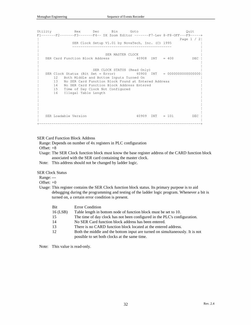
Monaghan Engineering Sequence of Events Recorder
Rev. 2.432
Utility Hex Dec Bin Goto QuitF1-------F2-------F3-------F4-- DX Zoom Editor -------F7-Lev 8-F8-OFF---F9-----+¦ Page 1 / 2¦¦ SER Clock Setup V1.01 by NovaTech, Inc. (C) 1995 ¦¦ ------------------------------------------------ ¦¦ ¦¦ SER MASTER CLOCK ¦¦ SER Card Function Block Address 40908 INT = 400 DEC ¦¦ ¦¦ ¦¦ SER CLOCK STATUS (Read Only) ¦¦ SER Clock Status (Bit Set = Error) 40900 INT = 0000000000000000¦¦ 12 Both Middle and Bottom Inputs Turned On ¦¦ 13 No SER Card Function Block Found at Entered Address ¦¦ 14 No SER Card Function Block Address Entered ¦¦ 15 Time of Day Clock Not Configured ¦¦ 16 Illegal Table Length ¦¦ ¦¦ ¦¦ ¦¦ ¦¦ ¦¦ SER Loadable Version 40909 INT = 101 DEC ¦¦ ¦+------------------------------------------------------------------------------+
SER Card Function Block Address Range: Depends on number of 4x registers in PLC configuration Offset: +8 Usage: The SER Clock function block must know the base register address of the CARD function block
associated with the SER card containing the master clock. Note: This address should not be changed by ladder logic.
SER Clock Status Range: --- Offset: +0 Usage: This register contains the SER Clock function block status. Its primary purpose is to aid
debugging during the programming and testing of the ladder logic program. Whenever a bit isturned on, a certain error condition is present.
Bit Error Condition16 (LSB) Table length in bottom node of function block must be set to 10.15 The time of day clock has not been configured in the PLC's configuration.14 No SER Card function block address has been entered.13 There is no CARD function block located at the entered address.12 Both the middle and the bottom input are turned on simultaneously. It is not
possible to set both clocks at the same time.
Note: This value is read-only.
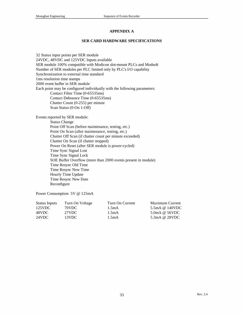
Monaghan Engineering Sequence of Events Recorder
Rev. 2.433
APPENDIX A
SER CARD HARDWARE SPECIFICATIONS
32 Status input points per SER module24VDC, 48VDC and 125VDC Inputs availableSER module 100% compatible with Modicon slot-mount PLCs and ModsoftNumber of SER modules per PLC limited only by PLC's I/O capabilitySynchronization to external time standard1ms resolution time stamps2000 event buffer in SER moduleEach point may be configured individually with the following parameters:
Contact Filter Time (0-65535ms)Contact Debounce Time (0-65535ms)Chatter Count (0-255) per minuteScan Status (0-On 1-Off)
Events reported by SER module:Status ChangePoint Off Scan (before maintenance, testing, etc.)Point On Scan (after maintenance, testing, etc.)Chatter Off Scan (if chatter count per minute exceeded)Chatter On Scan (if chatter stopped)Power On Reset (after SER module is power-cycled)Time Sync Signal LostTime Sync Signal LockSOE Buffer Overflow (more than 2000 events present in module)Time Resync Old TimeTime Resync New TimeHourly Time UpdateTime Resync New DateReconfigure
Power Consumption 5V @ 125mA
Status Inputs Turn On Voltage Turn On Current Maximum Current125VDC 70VDC 1.5mA 5.5mA @ 140VDC48VDC 27VDC 1.5mA 5.0mA @ 56VDC24VDC 13VDC 1.5mA 5.3mA @ 28VDC

Monaghan Engineering Sequence of Events Recorder
Rev. 2.434
APPENDIX B
SER CARD I/O WIRING
Terminal Use
1 Positive input for point 12 Positive input for point 23 Positive input for point 34 Positive input for point 45 Positive input for point 56 Positive input for point 67 Positive input for point 78 Positive input for point 89 Common ground for points 1 through 810 Positive input for point 911 Positive input for point 1012 Positive input for point 1113 Positive input for point 1214 Positive input for point 1315 Positive input for point 1416 Positive input for point 1517 Positive input for point 1618 Common ground for points 9 through 1619 Positive input for point 1720 Positive input for point 1821 Positive input for point 1922 Positive input for point 2023 Positive input for point 2124 Positive input for point 2225 Positive input for point 2326 Positive input for point 2427 Common ground for points 17 through 2428 Positive input for point 2529 Positive input for point 2630 Positive input for point 2731 Positive input for point 2832 Positive input for point 2933 Positive input for point 3034 Positive input for point 3135 Positive input for point 3236 Common ground for points 25 through 3237 RS-485 Output driver enable (Open collector drive for fiber optic interface)38 RS-485 A terminal39 RS-485 B terminal40 RS-485 ground
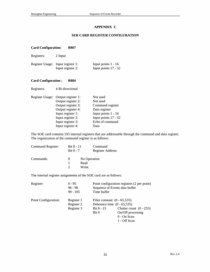
Monaghan Engineering Sequence of Events Recorder
Rev. 2.435
APPENDIX C
SER CARD REGISTER CONFIGURATION
Card Configuration: B807
Registers: 2 Input
Register Usage: Input register 1: Input points 1 - 16Input register 2: Input points 17 - 32
Card Configuration : B884
Registers: 4 Bi-directional
Register Usage: Output register 1: Not usedOutput register 2: Not usedOutput register 3: Command registerOutput register 4: Data registerInput register 1: Input points 1 - 16Input register 2: Input points 17 - 32Input register 3: Echo of commandInput register 4: Data
The SOE card contains 105 internal registers that are addressable through the command and data register.The organization of the command register is as follows:
Command Register: Bit 8 - 11 CommandBit 0 - 7 Register Address
Commands: 0 No Operation1 Read2 Write
The internal register assignments of the SOE card are as follows:
Register: 0 - 95 Point configuration registers (2 per point)96 - 98 Sequence of Events data buffer99 - 105 Time buffer
Point Configuration: Register 1 Filter constant (0 - 65,535)Register 2 Debounce time (0 - 65,535)Register 3 Bit 8 - 15 Chatter count (0 - 255)
Bit 0 On/Off processing0 - On Scan1 - Off Scan

Monaghan Engineering Sequence of Events Recorder
Rev. 2.436
SOE Data: Event types 0 - 12
Register 1 Bit 0 - 4 Event typeBit 13 Current statusBit 8 - 12 Point number (0 - 31)
Register 2 Bit 10 - 15 Seconds (0 - 59)Bit 0 - 9 Milliseconds (0 - 999)
Register 3 Bit 14 - 15 Time Quality00 - Good (GMT +/- 1mS)01 - Fair (GMT +/- 50mS)10 - Poor (GMT +/- > 50mS)11 - Bad (No time reference)
Bit 8 - 12 Hours (0 - 23)Bit 0 - 5 Minutes (0 - 59)
Event types 13 - 15
Register 1 Bit 0 - 4 Event typeBit 13 Current statusBit 8 - 12 Point number (0)
Register 2 Bit 9 - 13 Hour (0 - 23)Bit 4 - 8 Day (1 - 31)Bit 0 - 3 Month (1 - 12)
Register 3 Bit 14 - 15 Time Quality00 - Good (GMT +/- 1mS)01 - Fair (GMT +/- 50mS)10 - Poor (GMT +/- > 50mS)11 - Bad (No time reference)
Bit 0 - 12 Year (0 - 4095)
Note: Register 1 bit fields 8 - 13, Point Number and Current Status, are only valid for event types 1 - 5.All other event types indicate card level conditions and these bit fields will contain zeros.
Note: The bit assignments shown for Register 1 describe the data as it is retrieved from the card. Whenthe Card loadable is used to access the data, the bit assignments for Register 1 are modified to include thecard number. The data will appear in the SER data buffer as follows:
Register 1 Bit 0 - 4 Event typeBit 5 - 9 Point number (0 - 31)Bit 10 Current statusBit 11 - 15 Card Number (0 - 31)
SOE Event Types: 0 No Event1 Status Change2 On Scan3 Off Scan4 Chatter On Scan5 Chatter Off Scan6 Power On Reset7 Time Sync Signal Lock8 Time Sync Signal Lost9 SOE Buffer Overflow10 Scan Buffer Overflow

Monaghan Engineering Sequence of Events Recorder
Rev. 2.437
11 Time Resync Old Time12 Time Resync New Time13 Hourly Time Update14 Time Resync New Date15 Reconfigure
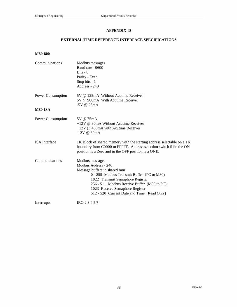
Monaghan Engineering Sequence of Events Recorder
Rev. 2.438
APPENDIX D
EXTERNAL TIME REFERENCE INTERFACE SPECIFICATIONS
M80-800
Communications Modbus messagesBaud rate - 9600Bits - 8Parity - EvenStop bits - 1Address - 240
Power Consumption 5V @ 125mA Without Acutime Receiver5V @ 900mA With Acutime Receiver-5V @ 25mA
M80-ISA
Power Consumption 5V @ 75mA+12V @ 30mA Without Acutime Receiver+12V @ 450mA with Acutime Receiver-12V @ 30mA
ISA Interface 1K Block of shared memory with the starting address selectable on a 1Kboundary from C0000 to FFFFF. Address selection switch S1in the ONposition is a Zero and in the OFF position is a ONE.
Communications Modbus messagesModbus Address - 240Message buffers in shared ram
0 - 255 Modbus Transmit Buffer (PC to M80)1022 Transmit Semaphore Register256 - 511 Modbus Receive Buffer (M80 to PC)1023 Receive Semaphore Register512 - 520 Current Date and Time (Read Only)
Interrupts IRQ 2,3,4,5,7

Monaghan Engineering Sequence of Events Recorder
Rev. 2.439
EXTERNAL TIME REFERENCEI/O WIRING
M80 - 800
Port 1 - 9 Pin D connector - Trimble Navigation Acutime ReceiverPin Description 1 RS-422 A terminal RX Data from receiver 2 RS-422 B terminal RX Data from receiver 3 RS-422 B terminal TX Data to receiver 4 RS-422 A terminal TX Data to receiver 5 RS-422 A terminal 1 Pulse / Second signal from receiver 6 RS-422 B terminal 1 Pulse / Second signal from receiver 7 Ground 9 +12 Volt - Power for receiver
Port 2 - 9 Pin D connector - Computer InterfacePin Description 2 RX Data from computer 3 TX Data to computer 4 Tied to pin 6 5 Ground 6 Tied to pin 4 7 Request to send 8 Clear to send
Port 3 - 9 Pin D connector - Printer Interface (Option M81-800 Only)Pin Description 2 RX Data from printer 3 TX Data to printer 4 Tied to pin 6 5 Ground 6 Tied to pin 4 7 Request to send 8 Clear to send
Port 4 - 50/60 Hz InputPin Description 1 9 - 24 VAC 2 9 - 24 VAC
Port 5 - 4 Position Phoenix connector - RS-485 PortPin Description 1 Output driver enable (Open collector drive for fiber optic interface) 2 RS-485 A terminal 3 RS-485 B terminal 4 RS-486 Ground
Port 6 - BNC Connector for Modulated IRIG-B Time Code Signal
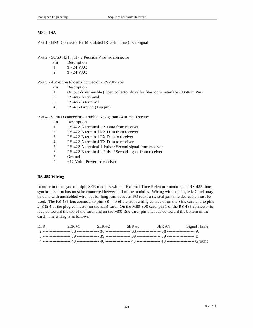
Monaghan Engineering Sequence of Events Recorder
Rev. 2.440
M80 - ISA
Port 1 - BNC Connector for Modulated IRIG-B Time Code Signal
Port 2 - 50/60 Hz Input - 2 Position Phoenix connectorPin Description 1 9 - 24 VAC 2 9 - 24 VAC
Port 3 - 4 Position Phoenix connector - RS-485 PortPin Description 1 Output driver enable (Open collector drive for fiber optic interface) (Bottom Pin) 2 RS-485 A terminal 3 RS-485 B terminal 4 RS-485 Ground (Top pin)
Port 4 - 9 Pin D connector - Trimble Navigation Acutime ReceiverPin Description 1 RS-422 A terminal RX Data from receiver 2 RS-422 B terminal RX Data from receiver 3 RS-422 B terminal TX Data to receiver 4 RS-422 A terminal TX Data to receiver 5 RS-422 A terminal 1 Pulse / Second signal from receiver 6 RS-422 B terminal 1 Pulse / Second signal from receiver 7 Ground 9 +12 Volt - Power for receiver
RS-485 Wiring
In order to time sync multiple SER modules with an External Time Reference module, the RS-485 timesynchronization bus must be connected between all of the modules. Wiring within a single I/O rack maybe done with unshielded wire, but for long runs between I/O racks a twisted pair shielded cable must beused. The RS-485 bus connects to pins 38 - 40 of the front wiring connector on the SER card and to pins2, 3 & 4 of the plug connector on the ETR card. On the M80-800 card, pin 1 of the RS-485 connector islocated toward the top of the card, and on the M80-ISA card, pin 1 is located toward the bottom of thecard. The wiring is as follows:
ETR SER #1 SER #2 SER #3 SER #N Signal Name 2 -------------------- 38 ---------------- 38 ------------------ 38 ----------------- 38 -------------------- A 3 -------------------- 39 ---------------- 39 ------------------ 39 ----------------- 39 -------------------- B 4 -------------------- 40 ---------------- 40 ------------------ 40 ----------------- 40 -------------------- Ground
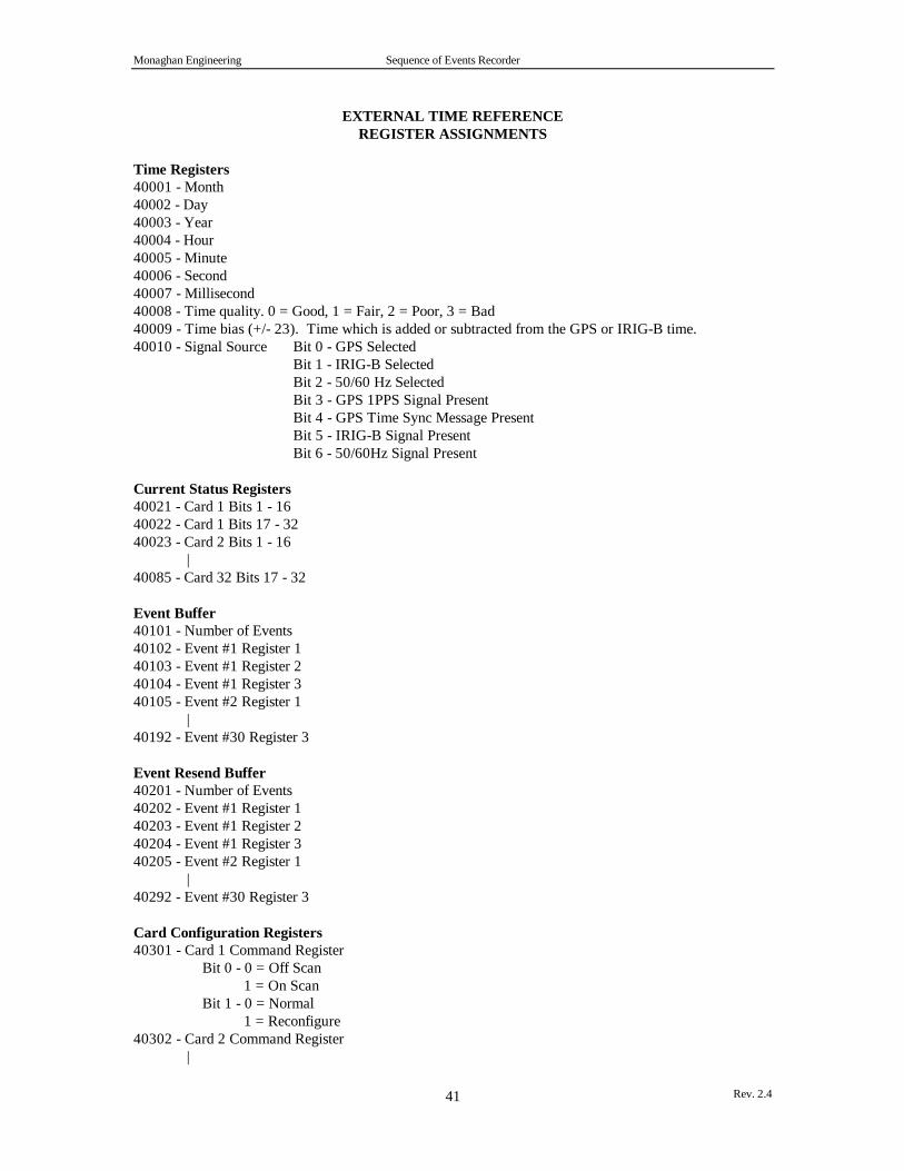
Monaghan Engineering Sequence of Events Recorder
Rev. 2.441
EXTERNAL TIME REFERENCEREGISTER ASSIGNMENTS
Time Registers40001 - Month40002 - Day40003 - Year40004 - Hour40005 - Minute40006 - Second40007 - Millisecond40008 - Time quality. 0 = Good, 1 = Fair, 2 = Poor, 3 = Bad40009 - Time bias (+/- 23). Time which is added or subtracted from the GPS or IRIG-B time.40010 - Signal Source Bit 0 - GPS Selected
Bit 1 - IRIG-B SelectedBit 2 - 50/60 Hz SelectedBit 3 - GPS 1PPS Signal PresentBit 4 - GPS Time Sync Message PresentBit 5 - IRIG-B Signal PresentBit 6 - 50/60Hz Signal Present
Current Status Registers40021 - Card 1 Bits 1 - 1640022 - Card 1 Bits 17 - 3240023 - Card 2 Bits 1 - 16
|40085 - Card 32 Bits 17 - 32
Event Buffer40101 - Number of Events40102 - Event #1 Register 140103 - Event #1 Register 240104 - Event #1 Register 340105 - Event #2 Register 1
|40192 - Event #30 Register 3
Event Resend Buffer40201 - Number of Events40202 - Event #1 Register 140203 - Event #1 Register 240204 - Event #1 Register 340205 - Event #2 Register 1
|40292 - Event #30 Register 3
Card Configuration Registers40301 - Card 1 Command Register
Bit 0 - 0 = Off Scan 1 = On Scan
Bit 1 - 0 = Normal 1 = Reconfigure
40302 - Card 2 Command Register|
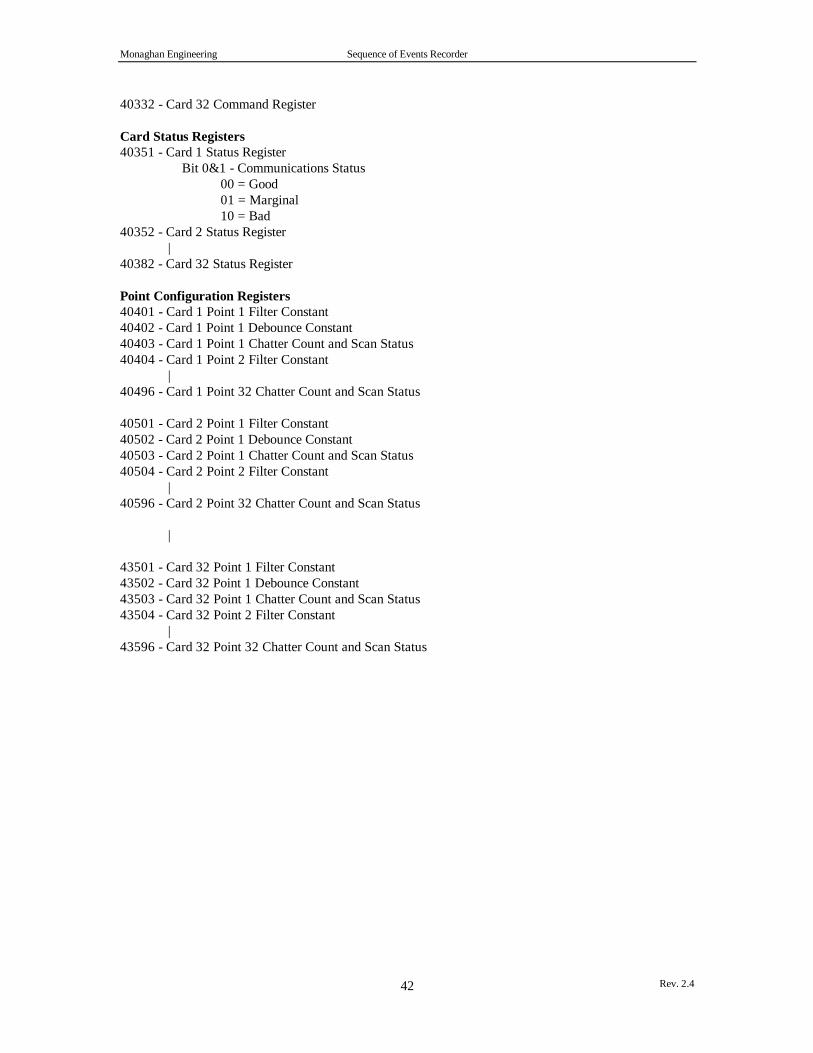
Monaghan Engineering Sequence of Events Recorder
Rev. 2.442
40332 - Card 32 Command Register
Card Status Registers40351 - Card 1 Status Register
Bit 0&1 - Communications Status 00 = Good 01 = Marginal 10 = Bad
40352 - Card 2 Status Register|
40382 - Card 32 Status Register
Point Configuration Registers40401 - Card 1 Point 1 Filter Constant40402 - Card 1 Point 1 Debounce Constant40403 - Card 1 Point 1 Chatter Count and Scan Status40404 - Card 1 Point 2 Filter Constant |40496 - Card 1 Point 32 Chatter Count and Scan Status
40501 - Card 2 Point 1 Filter Constant40502 - Card 2 Point 1 Debounce Constant40503 - Card 2 Point 1 Chatter Count and Scan Status40504 - Card 2 Point 2 Filter Constant |40596 - Card 2 Point 32 Chatter Count and Scan Status
|
43501 - Card 32 Point 1 Filter Constant43502 - Card 32 Point 1 Debounce Constant43503 - Card 32 Point 1 Chatter Count and Scan Status43504 - Card 32 Point 2 Filter Constant |43596 - Card 32 Point 32 Chatter Count and Scan Status

Monaghan Engineering Sequence of Events Recorder
Rev. 2.443
APPENDIX E
SER LOADABLE SPECIFICATIONS
SER Loadables run on all Modicon slot-mount PLCsSpecial templates in order to facilitate easy parameterization of loadablesTransmission of events via Modbus PlusTotal memory requirement: 2.3k (1.3k + 0.4k + 0.6k)
SER Card Loadable (CARD)Loadable Size 1.3kAverage Scan Time .5 msMaximum Scan Time < 1 ms4x Registers Required 130This loadable is used once for every SERmodule in the PLC. Thus, scan time andregisters requirements must be added upfor every SER module used.
SER Modbus Plus Loadable (CMBP)Loadable Size 0.4kAverage Scan Time .5 msMaximum Scan Time < 1 ms4x Registers Required 122This loadable is used only once in theentire ladder logic program.
SER Clock Loadable (CLCK)Loadable Size 0.6kAverage Scan Time .7 msMaximum Scan Time < 2 ms4x Registers Required 45This loadable is optional, and used onlyonce in the entire ladder logic program.
The scan times are based on a Modicon 984-385D PLC.