sequential processing for organic photovoltaics: design rules...
TRANSCRIPT

FULL P
APER
© 2015 WILEY-VCH Verlag GmbH & Co. KGaA, Weinheim (1 of 11) 1402020wileyonlinelibrary.com
Sequential Processing for Organic Photovoltaics: Design Rules for Morphology Control by Tailored Semi-Orthogonal Solvent Blends
Jordan C. Aguirre , Steven A. Hawks , Amy S. Ferreira , Patrick Yee , Selvam Subramaniyan , Samson A. Jenekhe , Sarah H. Tolbert , and Benjamin J. Schwartz*
DOI: 10.1002/aenm.201402020
1. Introduction
Recent advances have pushed the power conversion effi ciencies (PCEs) of polymer:fullerene photovoltaics to near 10%. [ 1,2 ] Despite encouraging progress in our understanding of these devices, [ 3–9 ] obtaining such effi ciencies has proven to be a major challenge due to the high sensitivity of device performance on the nm-scale morphology of the polymer and fullerene components. [ 10–17 ] To achieve the ideal nm-scale bulk heterojunction (BHJ) morphology for photovoltaic applications, two solution-based processing methods can be used: blend casting (BC) [ 18,19 ] and sequential processing (SqP). [ 20,21 ] With BC, which is by far the most common way in which organic photovoltaics are processed, the active layer is formed by blending the donor and acceptor materials together in solution prior to deposition of the blended fi lm. In SqP, the photovoltaic active layer is formed by depositing the donor and acceptor materials sequentially in sepa-rate steps, where the top layer is depos-ited from a semi-orthogonal solvent with respect to the bottom. [ 22 ] The SqP method is newer and has received far less atten-tion than the BC approach, but has shown great promise for the production of pol-ymer-based solar cells. [ 23–26 ] For example, it
has been demonstrated that SqP can produce fi lms with better macroscopic quality and scalability, [ 22,27 ] and yield devices with near-unity internal quantum effi ciencies that outperform their blend-cast counterparts. [ 28–30 ]
Although both SqP and BC are used to fabricate func-tional BHJ architectures, [ 22 ] the two processing routes build nm-scale networks in fundamentally different ways. The BC process relies on spontaneous demixing of the donor and acceptor materials, which occurs either during fi lm forma-tion or with post-deposition processing such as thermal or solvent annealing. [ 19,31–34 ] In contrast, SqP relies on swelling of the underlying donor layer by the solvent of the acceptor solution to facilitate quasi-solid-state interdiffusion of the two materials. [ 27,35,36 ] Additional fullerene also can be driven into the underlying polymer fi lm with post-deposition thermal annealing or solvent treatment. [ 37–42 ]
Design rules are presented for signifi cantly expanding sequential processing (SqP) into previously inaccessible polymer:fullerene systems by tailoring binary solvent blends for fullerene deposition. Starting with a base solvent that has high fullerene solubility, 2-chlorophenol (2-CP), ellipsometry-based swelling experiments are used to investigate different co-solvents for the fullerene-casting solution. By tuning the Flory-Huggins χ parameter of the 2-CP/co-solvent blend, it is possible to optimally swell the polymer of interest for fullerene interdiffusion without dissolution of the polymer underlayer. In this way solar cell power conversion effi ciencies are obtained for the PTB7 (poly[(4,8-bis[(2-ethylhexyl)oxy]benzo[1,2- b :4,5- b ′]dithiophene-2,6-diyl)-(3-fl uoro-2-[(2-ethylhexyl)carbonyl]thieno[3,4- b ]thiophenediyl)]) and PC 61 BM (phenyl-C 61 -butyric acid methyl ester) materials combination that match those of blend-cast fi lms. Both semicrystalline (e.g., P3HT (poly(3-hexylth-iophene-2,5-diyl)) and entirely amorphous (e.g., PSDTTT (poly[(4,8-di(2-butyloxy)benzo[1,2-b:4,5-b′]dithiophene-2,6-diyl)-alt-(2,5-bis(4,4′-bis(2-octyl)-dithieno[3,2-b:2′3′-d]silole-2,6-diyl)thiazolo[5,4-d]thiazole)]) conjugated polymers can be processed into highly effi cient photovoltaic devices using the solvent-blend SqP design rules. Grazing-incidence wide-angle x-ray diffraction experiments confi rm that proper choice of the fullerene casting co-solvent yields well-ordered interdispersed bulk heterojunction (BHJ) morphologies without the need for subsequent thermal annealing or the use of trace solvent additives (e.g., diiodooctane). The results open SqP to polymer/fullerene systems that are currently incompatible with traditional methods of device fabrication, and make BHJ morphology control a more tractable problem.
J. C. Aguirre, A. S. Ferreira, P. Yee, S. H. Tolbert, B. J. Schwartz Department of Chemistry and Biochemistry University of California Los A ngeles, Los A ngeles , CA 90095-1569 , USA E-mail: [email protected] S. A. Hawks, S. H. Tolbert Department of Materials Science and Engineering University of California Los A ngeles, Los A ngeles , CA 90095-1569 , USA S. Subramaniyan, S. A. Jenekhe Departments of Chemical Engineering and Chemistry University of Washington Seattle , WA 98195-1750 , USA S. H. Tolbert, B. J. Schwartz California NanoSystems Institute, University of California Los A ngeles, Los A ngeles , CA 90095 , USA
Adv. Energy Mater. 2015, 5, 1402020
www.MaterialsViews.comwww.advenergymat.de

FULL
PAPER
© 2015 WILEY-VCH Verlag GmbH & Co. KGaA, Weinheim1402020 (2 of 11) wileyonlinelibrary.com
Both the BC and SqP methods, however, have limitations when it comes to forming photovoltaic BHJ blends from new materials. For example, the spontaneous phase separation pro-cesses that drive blend-cast BHJ morphologies are still poorly understood and thus far from being rationally controlled. [ 43 ] This means that for every new material, a large processing parameter space (e.g., composition ratios, the use of solvent additives, [ 44–47 ] appropriate thermal annealing conditions, [ 33,34,48 ] etc.) must be explored via a ‘brute force’ approach in order to achieve an optimal BHJ network. [ 18,33,34,47 ] Because there are no guiding principles, blend-cast processing is mostly improved by purely Edisonian trial-and-error. SqP on the other hand, for all its promise, has only produced effi cient BHJ devices for a few systems, [ 20,30,42,49,50 ] largely because of diffi culties in fi nding the right semi-orthogonal solvent for casting the fullerene layer.
One reason for the relatively limited application of SqP is that many of its paradigms have been established for the poly(3-hex-ylthiophene-2,5-diyl) (P3HT) and phenyl-C 61 -butyric acid methyl ester (PCBM, Figure 4 a inset) materials combination, with dichloromethane (DCM) used as the PCBM casting solvent. [ 17,20 ] Optimal fabrication of these P3HT:PCBM SqP active layers, however, is unique in several important ways. First, P3HT does not signifi cantly swell in the presence of solvents due to its unu-sually high crystallinity, [ 51,52 ] which signifi cantly inhibits PCBM interdiffusion relative to most other polymer systems. In addi-tion, DCM's low boiling point (39.6 °C) results in the rapid depo-sition of large amounts of PCBM on top of P3HT fi lms, allowing time for only a small portion of the fullerene to intercalate into the polymer interior. [ 37,53–56 ] This results in a P3HT/PCBM quasi-bilayer structure that must be thermally annealed to drive the remaining fullerene into the amorphous regions of the polymer fi lm to form the requisite BHJ. [ 48,57 ] Fortunately, the hierarchical semi-crystalline structure of P3HT can tolerate such annealing—a property that many other photovoltaic conjugated polymers lack. [ 58 ] Thus, to this point, SqP research has been mostly focused on polymers that either have a low DCM solubility and a nm-scale structure stable enough for thermal annealing (e.g., P3HT) [ 59,60 ] or polymers that happen to swell an ideal amount when using DCM as the fullerene casting solvent. [ 28,36,42,49 ]
In this article, we address the problem of searching for orthogonal solvents for polymer:fullerene SqP by using high-boiling point co-solvent blends for fullerene deposition that can be tailored to ideally swell and wet essentially any conju-gated polymer of interest. The idea is to start with a low vapor-pressure base solvent in which fullerenes, such as PCBM, have an exceedingly high solubility and in which conjugated polymers have a generally low solubility. Fortunately, there are several solvents that meet these criteria, including alanine, tetrabromoethane, and tetrahydronapthalene, [ 61,62 ] as well as 2-chlorophenol (2-CP). [ 63 ] In this work, we choose to focus on 2-CP as our base solvent. We then pair 2-CP with co-solvents chosen so that the solvent blend optimally swells and wets the polymer of interest without dissolving it. Even though most of the co-solvents needed to swell and/or prevent the dissolu-tion of conjugated polymers are non-solvents for fullerenes, the high fullerene solubility of 2-CP (112 mg/ml for PCBM) [ 61 ] allows its co-solvent blends to produce stable fullerene solu-tions that yield consistent spin-cast fullerene fi lms. Moreover, by optimally swelling the polymer with the fullerene-casting
solvent blend, BHJ formation can occur without the need for subsequent thermal annealing. This allows SqP to be extended to high-effi ciency polymers whose nanostructure cannot tol-erate exposure to higher temperatures. [ 64–66 ]
In what follows we describe our method for designing SqP solvent blends. First, we use ellipsometry-based swelling meas-urements to better understand how swelling works in these conjugated molecular systems, since swelling is one of the key processes in SqP BHJ formation. Next, we demonstrate how our solvent-selection approach can be applied to two high-perfor-mance polymers that have very different degrees of crystallinity and solubility. Namely, we investigate the entirely non-crystalline poly[(4,8-di(2-butyloctyl)oxybenzo[1,2- b :4,5- b ′]dithiophene-2,6-diyl)-alt-(2,5-bis(4,4′-bis(2-octyl)dithieno[3,2- b :2′3′- d ]silole-2,6-diyl)thiazolo[5,4- d ]thiazole)] (PSDTTT) [ 67 ] and the extremely high-effi ciency poly[(4,8-bis[(2-ethylhexyl)oxy]benzo[1,2- b :4,5- b ′]dith-iophene-2,6-diyl)(3-fl uoro-2-[(2-ethylhexyl)carbonyl]thieno[3,4- b ]thiophenediyl)] (PTB7) [ 68 ] (Figure 2 b). Neither of these materials has been previously compatible with SqP, and we show that we can fabricate sequentially-processed PTB7:PCBM devices with effi ciencies that match those of blend-cast fi lms without the need for solvent additives (e.g., diiodooctane (DIO)), [ 46 ] thermal annealing, or any other type of post-deposition processing. We also explore how our design rules apply to highly crystalline polymers such as P3HT when the degree of fi lm crystallinity is controllably varied. [ 57 ] Thus, the SqP design rules we establish here open up an entire new avenue of morphology control in processing polymer:fullerene BHJ photovoltaics.
2. Results and Discussion
2.1. Understanding Conjugated Polymer Film Swelling for SqP
2.1.1. Using Porosimetry-Ellipsometry to Quantify Conjugated Polymer Film Swelling
To choose appropriate co-solvents to blend with 2-CP for fullerene deposition in SqP, we begin by examining how well a conjugated polymer fi lm swells with a given co-solvent using spectroscopic ellipsometry/porosimetry. [ 69–74 ] In these measure-ments the changes in a conjugated polymer fi lm's refractive index and thickness are monitored in a non-absorbing spec-tral region while the sample is exposed to controlled amounts of the co-solvent vapor (for experimental details, see the Sup-porting Information (SI)). Since most of the previous work on SqP is focused on P3HT, [ 20,22,37,38,48,56,57 ] we begin by examining the volume changes of swollen thin fi lms of P3HT that have varying degrees of crystallinity.
It is well known that amorphous regions of lower density in a semi-crystalline polymer fi lm are more susceptible to swelling than crystalline regions. [ 52,75 ] Indeed, the crystalline regions of a polymer fi lm are often treated as if they are cross-linked, hindering volume expansion of the fi lm because they are largely impenetrable to the solvent. [ 75 ] It is further known that P3HT crystallinity and therefore swelling can be controlled by the choice of deposition solvent and/or the application of post-deposition thermal annealing. [ 19,31 ] For example, casting P3HT from chloroform—a high vapor pressure solvent—leaves
Adv. Energy Mater. 2015, 5, 1402020
www.MaterialsViews.comwww.advenergymat.de

FULL P
APER
© 2015 WILEY-VCH Verlag GmbH & Co. KGaA, Weinheim (3 of 11) 1402020wileyonlinelibrary.com
the resulting fi lms relatively amorphous, while casting from a slower-drying solvent (e.g., orthodichlorobenzene (ODCB)) leaves P3HT fi lms that are signifi cantly more crystalline. [ 76 ] Therefore we would expect more crystalline P3HT fi lms spun from ODCB to swell less than more amorphous P3HT fi lms spun from chloroform.
Figure 1 a shows the results of spectroscopic porosimetry-ellipsometry measurements that compare the amount of P3HT swelling (dilation) in fi lms prepared from both slow- (ODCB) and fast- (chloroform) drying solvents; the fi gure shows the per-cent volume change as a function of the fraction of isopropyl alcohol (IPA) vapor saturation pressure. As expected, the extent of swelling and volume fraction of adsorbed solvent is reduced in the more crystalline P3HT fi lms deposited from ODCB (red curve, squares) compared to the more amorphous P3HT fi lms spun from chloroform (blue curve, circles). Moreover, if we thermally anneal the fi lms cast from chloroform, increasing their crystallinity and decreasing the total amount of void space, we see that the degree of swelling and IPA adsorption is reduced to a level similar to that of fi lms cast from ODCB (green curve, triangles).
We can quantitatively determine the amount of solvent uptake within the polymer fi lm from the data in Figure 1 a using the (Bruggeman) effective medium approximation (EMA), which takes the known refractive indices of the unswollen polymer fi lm and the pure solvent, along with that measured for the solvent-swollen fi lm, to estimate the volume fraction of adsorbed solvent within the fi lm (for further details see the SI). [ 74,77–79 ] Figure 1 b shows a nearly linear relationship between the volume fraction of solvent within the fi lm, deter-mined by the EMA, and the total fi lm dilation. This indicates that for P3HT, polymer crystallinity has little effect on the extent of fi lm dilation per unit volume of adsorbed solvent. Thus, Figure 1 b demonstrates that the reason why amorphous P3HT fi lms swell more than crystalline P3HT fi lms is because the more amorphous fi lms adsorb more solvent molecules at a given pressure. For example, our more amorphous P3HT polymer fi lms can accommodate about twice as much adsorbed solvent as the more crystalline P3HT fi lms, even though the amount of swelling at a given amount of solvent uptake is only slightly different. This means that for conjugated polymers like
P3HT, the swelling of a fi lm can be tuned by any means that changes how much sol-vent is incorporated into the fi lm. The data in Figure 1 also demonstrate that examina-tion of polymer swelling upon exposure to a controlled amount of solvent can be a useful tool for comparing the relative crystallinities of different conjugated polymer fi lms with the same composition. (The slight non-lin-earity seen in Figure 1 b likely results from the fi lling of void spaces in the fi lm by the solvent upon initial exposure to the solvent vapor. [ 80 ] )
Finally, we note that these results give insight to our previous work using P3HT for sequentially-processed BHJ solar cells, where we found that when we changed the degree of P3HT crystallinity by changing the
regioregularity of the polymer chains, we could dramatically tune the amount of intercalated fullerene and thus the device perfor-mance. [ 57 ] In particular, we found that as we decreased the P3HT crystallinity, traditional blend-cast devices had their performance suffer, but the performance of sequentially-processed devices improved because there was more swelling of the polymer under-layer leading to better fullerene intercalation and photocurrent. [ 57 ] We therefore conclude that porosimetry-ellipsometry measure-ments can be used to understand—and thus ultimately manipu-late—the extent of fullerene intercalation into polymer/fullerene active layers produced by SqP. Hence, by controlling the degree of underlayer swelling, [ 57 ] SqP offers a more rational route to polymer:fullerene BHJ formation.
2.1.2. Quantifying Conjugated Polymer Swelling for SqP
Now that we know that porosimetry-ellipsometry can be used to investigate the degree of polymer swelling, we can use this tool to quantitatively examine solvent swelling in two high-perfor-mance photovoltaic polymers: PTB7 (see Figure 2 b for chemical structure), a slightly crystalline polymer with extremely high per-formance in blend-cast devices, [ 68 ] and PSDTTT (see Figure 2 a for chemical structure), an entirely amorphous polymer with exceedingly low solubility in most common organic solvents. [ 67 ] Figure 2 c shows the swelling of these two conjugated polymers upon exposure to both toluene and IPA vapor. We chose tol-uene and IPA both because of their miscibility with 2-CP and because they are among a select list of solvents that are com-patible with the porosimeter-ellipsometer instrument in our laboratory. Since swelling is a fundamental step in polymer dis-solution, [ 81 ] solvents with higher polymer solubility are better able to swell the polymer fi lms due to more extensive solvent uptake. Thus, the swelling of both PTB7 and PSDTTT with tol-uene is greater than with IPA, which is a non-solvent for both polymers. Furthermore, PTB7 swells around four times more than PSDTTT with either solvent, a refl ection of the latter's generally low solubility. [ 67 ]
We can further analyze the amount of solvent adsorbed into both polymer fi lms using the EMA. As with P3HT, we fi nd a nearly linear dependence of the fi lm volume change with
Adv. Energy Mater. 2015, 5, 1402020
www.MaterialsViews.comwww.advenergymat.de
Figure 1. Porosimetry-ellipsometry measurements of (a) the percent volume change, and (b) volume percent of solvent absorbed as a function of the fraction atmospheric isopropanol saturation for P3HT fi lms prepared with different degrees of crystallinity by casting from dif-ferent solvents and/or thermal annealing. The inset shows the chemical structure of P3HT.

FULL
PAPER
© 2015 WILEY-VCH Verlag GmbH & Co. KGaA, Weinheim1402020 (4 of 11) wileyonlinelibrary.com
adsorbed solvent volume, independent of the choice of swelling solvent, as seen in Figure 2 d. Thus, for these solvent/polymer combinations, the extent of polymer swelling depends only on how much solvent is adsorbed into the fi lm and not on the type of solvent molecule used. The amount of adsorbed solvent, however, is of course highly dependent on: the choice of sol-vent, the molecular specifi cs of the solvent-polymer interaction, and the particular way in which the polymer underlayer was processed.
The question now becomes: how can we quantifi ably cap-ture these interactions? One approach would be to use a sol-vation index, such as the Hansen solubility parameters, [ 62,82 ] to help select solvents with an ideal polymer-solvent interaction. As described in more detail in the SI, however, we found dif-fi culty in correctly predicting known polymer solubilities even in pure solvents using this method. Moreover, a solvation index like the Hansen solubility parameters cannot account for solid-state effects, such as how polymer-fi lm crystallinity infl uences swelling. [ 83 ] Instead, we can quantify the solvent-polymer fi lm interaction by calculating Flory-Huggins interaction parameters ( χ ) from the results of our swelling experiments (see SI for Flory-Huggins calculation details). [ 51,70,71,74,84 ]
Figure 3 a shows the calculated values of χ for the solvent-polymer fi lm pairs explored in Figure 2 ; stronger solvent-pol-ymer fi lm interactions give lower values for χ . As expected, toluene—the better solvent for both PTB7 and PSDTTT—gives uniformly lower χ values than IPA. Furthermore, PSDTTT has higher χ values than PTB7 for a given solvent, as expected given PSDTTT's generally poor solubility. Comparing Figure 2 d to Figure 3 a for PTB7 and PSDTTT, we fi nd that increasing the χ value by a factor of ∼2.4 gives an approximately three-fold increase is solvent uptake and therefore fi lm swelling. Thus,
solvent-polymer fi lm compatibility makes a dramatic difference in how much a conju-gated polymer fi lm will swell in the presence of solvent and therefore how extensive the polymer and fullerene components will mix during SqP.
As discussed above, in addition to molec-ular polymer-solvent interactions, the pol-ymer-layer morphology also can signifi cantly infl uence χ . This is exemplifi ed by Figure 3 b, which shows χ calculated from IPA-swollen P3HT fi lms that were processed under dif-ferent conditions. Figure 3 b fi rst demon-strates that the absolute magnitude of χ is quite large for P3HT/IPA compared to the other polymer/IPA combinations (Figure 3 a). This fi ts well with the notion that P3HT's unusually high crystallinity renders it more impervious to solvent infi ltration. Second, Figure 3 b shows that the χ value for P3HT/IPA swollen fi lms can shifted by ∼17% simply by using a different solvent to cast the P3HT fi lm or thermally annealing it. This is fully consistent with our expectations as to how the different thin-fi lm morphologies that result from different processing condi-tions infl uence solvent swelling. Thus, we
conclude that the Flory-Huggins χ parameter is an excellent way to quantify conjugated polymer swelling and therefore polymer:fullerene BHJ formation by SqP. Notably, we are aware of no such means of simply quantifying the nanoscale phase separation processes that govern traditional blend-cast BHJ morphologies.
2.1.3. Solvent Design Rules for SqP Based on Polymer Swelling
Now that we quantitatively understand how conjugated polymer fi lms swell when exposed to different solvents, we want to use this knowledge to design solvent blends to use as the fullerene-casting solvent in SqP in order to optimize BHJ formation and thus photovoltaic effi ciency. For our SqP solvent-blend design rules, we do not want the fullerene casting sol-vent to dissolve the underlying conjugated polymer fi lm, but we do want to strongly swell the fi lm without destroying the more dense/ordered polymer regions. Thus, we should choose a χ that is as low as possible within these constraints for a given polymer-(co-)solvent combination. Based on our expe-rience, pure toluene dissolves PTB7 too well to be used as a fullerene deposition solvent for SqP ( χ ≈ 0.4), but as we show below it makes an excellent swelling co-solvent for PSDTTT ( χ ≈ 1.4) when paired with a non-solvent ( χ � 3). Thus we can estimate that a ‘good’ SqP swelling (co)solvent will have an effective χ that is roughly in the range 1.4 � χ � 2. More work is needed to determine a more precise χ value for creating ideal sequentially-processed BHJs, but the main point is that the essential aspects of polymer fi lm swelling—the basis of polymer:fullerene BHJ creation by SqP—can be readily quan-tifi ed and understood. This is in stark contrast to traditional
Adv. Energy Mater. 2015, 5, 1402020
www.MaterialsViews.comwww.advenergymat.de
Figure 2. Upper panels: Chemical structures of a) PSDTTT and b) PTB7. Lower panels: A comparison of the extent of c) PSDTTT and PTB7 thin fi lm volume change upon exposure to toluene and isopropanol vapor as measured by ellipsometry; see SI for details. The saturation pressures ( p sat ) are 29 and 45 torr for toluene and isopropanol, respectively. d) The fi lm volume increase as a function of intercalated solvent measured within the fi lm. As expected, the better solvent (toluene) provides greater swelling for both conjugated polymer fi lms, and the more soluble polymer PTB7 swells signifi cantly better than the poorly soluble PSDTTT.

FULL P
APER
© 2015 WILEY-VCH Verlag GmbH & Co. KGaA, Weinheim (5 of 11) 1402020wileyonlinelibrary.com
blend-cast processing, which relies on poorly understood spon-taneous nanoscale phase separation in the presence of solvent evaporation to create a BHJ morphology. In what follows, we use this knowledge of conjugated polymer swelling and the χ parameter with different solvents to create high-performance sequentially-processed polymer/fullerene photovoltaic devices in materials systems that were previously inaccessible to SqP.
2.2. Creating High Performance BHJ OPVs with the SqP Co-Solvent Approach
Now that we have a sense of how two potential co-solvents—toluene and IPA—can swell the amorphous regions of different conjugated polymer fi lms, we turn toward using blends of these co-solvents with 2-CP to directly form high-performance BHJ photovoltaic devices via SqP. Previous work has shown that blends of good solvents and non-solvents can readily swell polymer fi lms, [ 85,86 ] so the information in Figures 2 c and 2 d are directly relevant to mixtures with the 2-CP base solvent.
We consider two cases when designing a blended fullerene deposition solvent: polymers that are insoluble in 2-CP (e.g., PSDTTT), and polymers that are soluble in 2-CP (e.g., PTB7). When 2-CP does not dissolve the polymer underlayer, swelling must be increased (i.e., χ must be decreased) by blending 2-CP with a good solvent for the polymer. The fraction of good solvent can be increased until χ is in the range of optimal swelling, just before dissolution of the polymer fi lm. When 2-CP dissolves a conjugated polymer fi lm, on the other hand, the polymer solu-bility must be reduced (i.e., χ must be increased) by blending 2-CP with a polymer non-solvent. The ratio of the non-solvent to 2-CP is increased until the fi lm no longer dissolves but still optimally swells the polymer, allowing for interdiffusion and BHJ creation. These ideas thus serve as design rules for the SqP of any polymer/fullerene photovoltaic active layer. We tested a number of 2-CP:co-solvent blends to fi nd the point of viable fi lm dissolution for the polymers chosen for this study, and some of the results are summarized in Table 1 . We note that the solar cell performance data in Table 1 do not represent exhaustively optimized devices, which bodes well for our approach since the performance is already respectably good.
It is also important to note that care must be taken when selecting polymer non-solvents to blend with 2-CP because reducing the solvent-polymer interaction (increasing χ ) to hinder dissolution also can reduce polymer wetting, which can prevent the deposition of a smooth fullerene overlayer. Thus, any non-solvents combined with 2-CP must be chosen to pro-duce a solvent blend that still wets the polymer fi lm. This is why we chose IPA as our typical non-solvent, since alcohols readily wet most conjugated polymers as well as maintain or even enhance their swelling. [ 85–89 ]
2.2.1. Selecting Co-Solvents for Polymers not Soluble in the Fullerene Base Solvent
We begin a more detailed application of the above SqP sol-vent blend design rules with the conjugated polymer PSDTTT. PSDTTT has poor solubility in most organic solvents (blend-cast solutions of this polymer must be heated to 120 °C prior to depo-sition). When blend-cast devices are fabricated from heated solu-tions of this material and PC 71 BM, they have PCEs of 5.3%. [ 67 ] For SqP, we found that at room temperature, PSDTTT is com-pletely insoluble in 2-CP ( χ � 2.5). Thus, following the design rules outlined above for creating a fullerene-overlayer-casting solvent for SqP, we chose to fabricate SqP devices by depositing PCBM from a blend of 2-CP with toluene as the co-solvent. This is because toluene increases PSDTTT solubility, lowering χ and thus facilitating swelling. As a control experiment, we also prepared SqP devices with the fullerene layer cast from 2-CP blended with IPA, a non-solvent for PSDTTT that poorly swells the polymer (cf. Figure 2 c), leaving χ relatively unchanged or raising it to an even more unfavorable value. Both IPA and tol-uene suffi ciently wet PSDTTT fi lms (as shown in Figure S6 of the SI), so the use of either co-solvent should ensure that spin-coating produces an even distribution of PCBM.
Figure 4 a shows the current-voltage characteristics of sequen-tially-processed devices fabricated with the PSDTTT layer cast from chlorobenzene and the PCBM overlayer cast from blends
Adv. Energy Mater. 2015, 5, 1402020
www.MaterialsViews.comwww.advenergymat.de
Figure 3. Flory-Huggins interaction parameters ( χ ) for a) PTB7 and PSDTTT fi lms swelled with IPA and toluene and b) P3HT fi lms cast from different solvents swelled with IPA. A lower value of χ implies a more favorable solvent-polymer fi lm interaction. We fi nd that a value of χ ≈ 0.4 is too low for SqP because it results in partial dissolution of the underlying polymer fi lm and that a value of χ ≈ 3 is too high for SqP because it does not result in signifi cant swelling and therefore fullerene interpenetration.

FULL
PAPER
© 2015 WILEY-VCH Verlag GmbH & Co. KGaA, Weinheim1402020 (6 of 11) wileyonlinelibrary.com
of 2-CP with both toluene (blue curve, pentagon symbols) and IPA (green curve, hourglass symbols) under simulated AM1.5G illumination; the details of the device fabrication and the full
device J – V characteristics are summarized in Table 1 . We note that these devices were prepared without thermal annealing or any other post-deposition processing, so that mixing of the
fullerene into the polymer layer occurred only during the sequential deposition of the fullerene layer from the blended solvent.
Clearly, Figure 4 a shows that choosing the appropriate solvent blend (in this case 65:35 v/v 2-CP:Toluene, χ ≈1.5, see Table 1 ) to swell the PSDTTT underlayer allows PCBM to intercalate into the underlying polymer fi lm, leading to a desirable BHJ morphology that produces reasonably effi cient photovoltaic devices with PC 61 BM (PCE = 3.8%). This device effi ciency is comparable to blend-cast PSDTTT:PC 61 BM fabricated following the methods detailed in the literature (see SI Figure S8), [ 67 ] although we note that the blend-cast and sequentially-processed devices were not rigorously thickness- or composi-tion-matched. [ 22 ] In contrast, if we choose an inappropriate, non-swelling solvent blend (such as 70:30 v/v 2-CP:IPA, χ �2.5), PCBM does not mix into the PSDTTT underlayer, but instead deposits on top. This is con-fi rmed by optical microscopy (see the images displayed in Figure S7 of the SI), where no change is observed for PSDTTT fi lms after
Adv. Energy Mater. 2015, 5, 1402020
www.MaterialsViews.comwww.advenergymat.de
Table 1. Photovoltaic Device Performance.
Polymer a) Co-Solvent with 2-CP
2-CP/Co-solvent Ratio [v/v]
Film Dissolved Annealedb) V OC [V] c)
J SC [mA/cm 2 ] c)
Fill Factor [%] c)
Effi ciency c,d) [%]
PSDTTT Isopropyl alcohol 70/30 No No 0.63 ± 0.05 0.1 ± 0.1 31 ± 2 0.03 ± 0.01
PSDTTT Toluene 65/35 No No 0.3 ± 0.1 5.0 ± 0.3 34 ± 6 0.6 ± 0.3
PSDTTT Toluene 35/65 No No 0.73 ± 0.01 9.5 ± 0.8 54 ± 2 3.8 ± 0.04
PSDTTT Toluene 25/75 Yes e) No – – – –
PSDTTT Blendcast f) – – No 0.78 ± 0.01 6.8 ± 0.4 66 ± 1 3.6 ± 0.2
PTB7 Isopropyl alcohol 60/40 No No 0.65 ± 0.02 3.0 ± 0.4 52 ± 3 1.0 ± 0.2
PTB7 Isopropyl alcohol 70/30 No No 0.75 ± 0.01 12.7 ± 0.7 43 ± 1 4.3 ± 0.3
PTB7 Isopropyl alcohol 80/20 Yes e) No – – – –
PTB7 Dimethylformamide 75/25 No No 0.68 ± 0.2 0.9 ± 0.2 25 ± 1 0.1 ± 0.1
PTB7 1-Butanol 50/50 No No 0.76 ± .01 13.7 ± 0.8 57 ± 1 6.0 ± 0.4
PTB7 Blendcast g) – – No 0.74 ± .01 13.3 ± 0.3 57 ± 1 5.9 ± 0.3
P3HT Toluene 60/40 No No 0.52 ± .01 3.8 ± 0.1 42 ± 2 0.8 ± 0.2
P3HT Toluene 65/35 No No 0.50 ± .02 6.4 ± 0.6 45 ± 3 1.4 ± 0.2
P3HT Toluene 70/30 Yes e) No 0.5 ± .01 5.6 ± 0.9 43 ± 2 1.2 ± 0.2
P3HT Toluene 65/35 No Yes 0.63 ± .01 8.0 ± 0.5 62 ± 1 3.1 ± 0.3
P3HT DCM 0/100 No No 0.47 ±.01 3.7 ± 0.9 56 ± 3 1.0 ± 0.2
P3HT DCM 0/100 No Yes 0.63 ± .01 7.7 ± 0.5 64 ± 3 3.1 ± 0.2
a) All polymer layers deposited from a 10mg/mL polymer/chlorobenzene solution at 1000 rpm; b) Films thermally annealed at 150 °C for 10 minutes; c) Standard deviation given; d) All devices use PC 61 BM as the electron acceptor. The device architecture is ITO/PEDOT:PSS (35 nm)/Active Layer ( 90 nm)/Ca (5 nm)/Al(70 nm); e) Polymer fi lm was partially removed from the substrate; f) Blend-cast fi lm is 1:1.5 PSDTTT:PC 61 BM spin-cast from a 10 mg/mL PSDTTT/chlorobenzene solution deposited at 1000 rpm at 120 °C; g) Blend-cast fi lm is 1:1.5 PTB7:PC 61 BM spin-cast from a 10 mg/mL PTB7/chlorobenzene solution with 3% v/v diiodooctane as a solvent additive, deposited at 1000 rpm.
Figure 4. Photovoltaic device performance of SqP active layers containing: a) PSDTTT and b) PTB7 and PCBM under standard AM1.5G illumination. For these devices, the polymer under-layer was spun from chlorobenzene solvent, and the PCBM overlayer deposited from different 2-CP co-solvent blends. For devices containing PSDTTT the fullerene was dissolved in 70:30 2-CP:IPA and 35:65 2-CP:Toluene. For devices containing PTB7 the fullerene solutions used were 75:25 2-CP:DMF and 70:30 2-CP:IPA. Average device effi ciencies for the PSDTTT samples are 0.005% and 3.5% when IPA and toluene are used as co-solvents, respectively. For PTB7 devices, the average effi ciencies are 4.3% and 0.1% when IPA and DMF are used as co-solvents, respectively. See the SI and Table 1 for details of the device fabrication.

FULL P
APER
© 2015 WILEY-VCH Verlag GmbH & Co. KGaA, Weinheim (7 of 11) 1402020wileyonlinelibrary.com
PCBM is deposited from the swelling solvent blend, other than a uniform darkening of the fi lm due to PCBM incorporation, but large isolated spots of PCBM are observed when the non-swelling solvent blend is used. This is because the 2-CP:IPA blend does not swell the PSDTTT underlayer, so drops of the PCBM solution remain after spin coating, and these droplets eventually evaporate to leave small deposits of fullerene on top of the polymer fi lm. [ 49 ] Not surprisingly, the devices pro-duced from these unmixed SqP fi lms have almost no interior donor/acceptor interface and thus have an extremely poor photocurrent.
To understand the structural aspects of fullerene intercala-tion caused by the swelling of PSDTTT with different solvent blends during SqP, we turn to grazing-incidence wide-angle X-ray scattering (GIWAXS). Figure 5 a shows radially-integrated diffractograms of the pure polymer fi lms and the sequentially-processed fi lms made with the fullerene overlayer cast from the 35:65 2-CP:toluene solution. When PCBM is sequen-tially deposited on top of the PSDTTT fi lm, a loss of polymer ordering is observed as evidenced by the decreased magnitude of the (100) diffraction peak centered at 0.3 Å −1 , which corre-sponds to the lamellar stacking of the PSDTTT polymer chains. The sequentially-processed fi lm also shows an increase in the full width at half maximum (FWHM) of this peak compared to the pure polymer fi lm, indicating a decrease in the average crystallite domain size. Values for the measured FWHM and peak areas are given in Table S2 of the SI. Both of these obser-vations are consistent with the fact that fullerene has interca-lated into the sequentially-processed PSDTTT fi lm, disrupting what little ordering the fi lm possessed and shrinking the size of the pre-existing polymer crystallites. We confi rmed that these structural changes are not caused by the swelling solvent
by performing control experiments on fi lms treated with the solvent blend without any fullerene, which show no change in their (010) diffraction peak, as demonstrated in Figure S4a of the SI. This supports the claim that the solvent swells the amorphous regions of the polymer fi lm, leaving the crystalline regions unchanged. [ 52,75 ]
The presence of the broad X-ray diffraction feature cen-tered at 1.4 Å −1 in Figure 5 a also supports the idea of fullerene intercalation, since this peak is a signature of PCBM in the interior of the fi lm. If there were a signifi cant amount of bulk-like PCBM in small crystallites deposited on top of the fi lm, this would lead to narrow diffraction peaks superimposed on the broader background. [ 34 ] It is worth noting that the broad fullerene feature centered at 1.4 Å −1 lies on top of the poly-mer's (010) scattering peak. We can confi rm that the (010) polymer peak remains unchanged in SqP fi lms, however, by subtracting out the fullerene signal as shown in Figure S5 of the SI.
2.2.2. Selecting Co-Solvents for Polymers Soluble in the Fullerene Base Solvent
We now switch our focus to PTB7, another polymer that thus far has been incompatible with SqP because it is too soluble in DCM. PTB7 fi lms also are slightly soluble in 2-CP ( χ � 1) and quite soluble in toluene ( χ ≈ 0.4). This means that the 2-CP:toluene blends we used for SqP of PSDTTT active layers cannot be used for PTB7 since the fi lms would be soluble in both solvent com-ponents. Thus, following our design rules, SqP of PTB7 requires a blend of 2-CP with a non-solvent that will decrease the polymer solubility but enhance (or at least maintain) the natural swelling of PTB7 that takes place with 2-CP, [ 85,86,88 ] bringing χ into the optimal range. As mentioned above, we also need to choose non-solvents that still allow the fullerene casting solution to ade-quately wet the polymer underlayer.
To fi nd an appropriate non-solvent, we fabricated PTB7:PCBM SqP devices with blends of 2-CP with different co-solvents that possess varying propensities to wet the polymer fi lm. We found that IPA and dimethylformamide (DMF) act as representative wetting and non-wetting sol-vents, respectively. Figure S6 in the SI shows the results of contact angle measurements for both of these co-solvents on PTB7; the results give a 3° contact angle for IPA and 38° con-tact angle for DMF. This indicates small amounts of IPA can easily cover the entire PTB7 fi lm surface, while DMF poorly wets the PTB7 surface. Though enough DMF can be used to eventually cover the PTB7 fi lm, this solvent is easily removed during deposition, leaving behind drops of fullerene that deposit onto the fi lm's surface. The resulting performance of SqP devices with the fullerene deposited from blends of these representative co-solvents with 2-CP is shown in Figure 4 b and summarized in Table 1 . As expected, the fullerene solu-tion that both wets and swells the PTB7 polymer fi lm (70:30 2-CP:IPA, χ ≈ 1.4) is able to form a BHJ network and give good device effi ciency, whereas the fullerene solution that swells but does not wet (75:25 2-CP:DMF χ � 2.5) produces sequentially-processed fi lms that exhibit poor device perfor-mance (Figure 4 and Table 1 ).
Adv. Energy Mater. 2015, 5, 1402020
www.MaterialsViews.comwww.advenergymat.de
Figure 5. a) GIWAXS diffractorgram of pure (solid red curve) and sequentially-processed (dashed blue curve) as-cast PSDTTT:PCBM fi lms. The FWHM values of the polymer (100) peak at 0.3 Å −1 are 0.08 and 0.11, respectively. b) GIWAXS diffractogram comparing thin fi lms of pure PTB7 (black dashed curve) with sequentially-processed PTB7:PCBM fi lms with the PCBM overlayer spun from a 70:30 2-CP:IPA solution (blue solid curve) and a 50:50 2-CP:1-BuOH solution (red dotted curve). The apparent shift of the (100) peak in both SqP devices is due to the pres-ence of an underlying PCBM peak at ∼0.7 Å −1 ; this apparent shift is also observed in PTB7 blend-cast devices.
FULL
PAPER
© 2015 WILEY-VCH Verlag GmbH & Co. KGaA, Weinheim1402020 (8 of 11) wileyonlinelibrary.com
It is worth noting that our initial choice of IPA as a repre-sentative non-solvent was due to its compatibility with the porosimeter-ellipsometer used for our swelling measurements. The 2-CP:IPA blend used to produce the SqP devices in Figure 4 b still has a slightly too high solubility for PTB7. This can be seen in the GIWAXS data shown in Figure 5 b, which shows that the magnitude of the PTB7 (100) lamellar stacking peak (black dashed curve) undergoes a sizable increase after SqP with the 2-CP:IPA blend (blue solid curve). This indicates that this par-ticular SqP solvent blend has a χ low enough to alter the struc-ture of the underlying polymer fi lm rather than simply swelling it to enable fullerene intercalation. We believe that use of this co-solvent blend increases PTB7 diffraction because the solvent re-dissolves part of the polymer and then recrystallizes it upon drying, similar to solvent annealing. [ 90,91 ] Regardless, such dramatic changes in fi lm structure run counter to the ideas of SqP, where device reproducibility is guaranteed by the fact that polymer fi lms swell without dramatic restructuring of their morphology. As a result, for SqP we would like to avoid signifi -cant changes in polymer morphology upon fullerene intercala-tion like those shown in Figure 5 b.
Since conjugated polymer dissolution decreases ( χ increases) with increasing alcohol chain length in solvent blends, [ 85,88,89,92 ] we decided to use 1-butanol (1-BuOH), a linear and longer-chain alcohol, as the fullerene casting co-solvent to hinder the dissolution of PTB7 during fullerene deposition. This choice of co-solvent indeed prevents structural changes in the PTB7 fi lms, as seen by comparing the X-ray diffraction (100) peak area of a pristine PTB7 fi lm (black dashed curve) to SqP fi lms fabricated using a 2-CP:1-BuOH mixture as the swelling solvent (red-dotted curve) in Figure 5 b. We also confi rm that the 2-CP:BuOH blends do not restructure the fi lm by dem-onstrating that there is no change in (010) peak when the co-solvent blend is spun onto PTB7 without any fullerene, as shown in Figure S4 of the SI. This means that unlike with IPA, the use of 1-BuOH leaves the polymer crystallinity relatively unchanged, so that this co-solvent causes enough swelling to enable fullerene intercalation without signifi cant reorganization of the polymer chains. Overall, the simple and rational switch from IPA to 1-BuOH shows that with the proper solvent com-bination, fullerene incorporation into easily-dissolving polymer fi lms can be achieved without causing a signifi cant change in structure from the pure polymer fi lm.
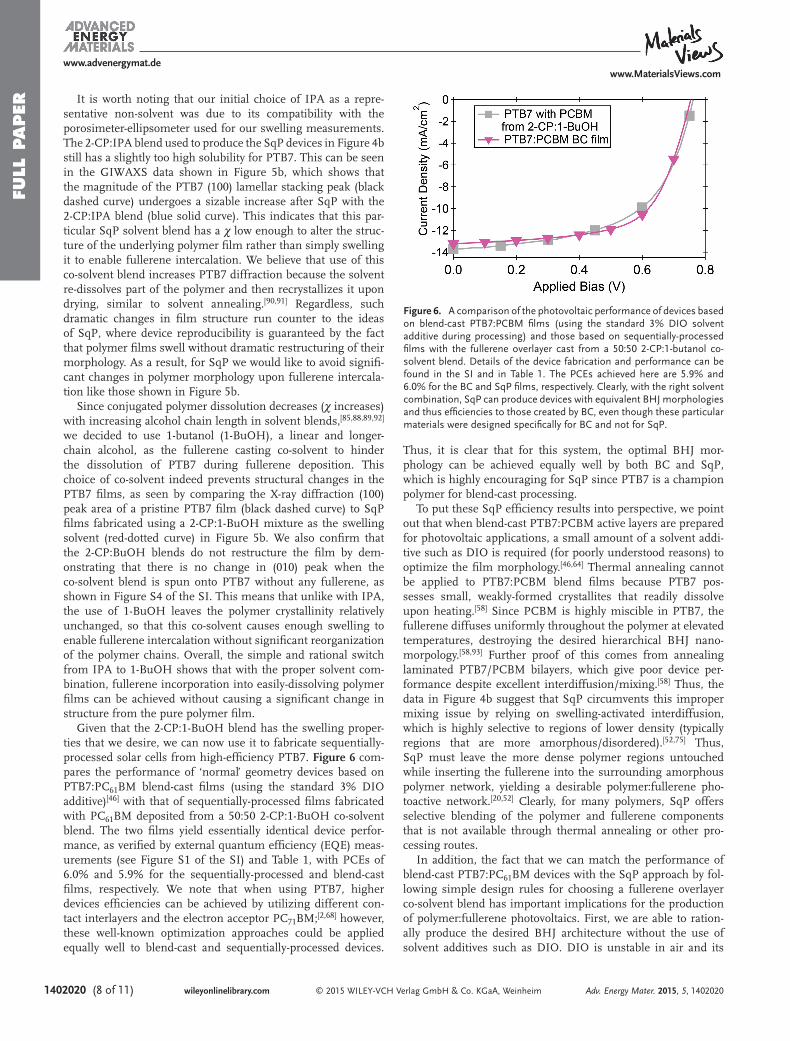
Given that the 2-CP:1-BuOH blend has the swelling proper-ties that we desire, we can now use it to fabricate sequentially-processed solar cells from high-effi ciency PTB7. Figure 6 com-pares the performance of ‘normal’ geometry devices based on PTB7:PC 61 BM blend-cast fi lms (using the standard 3% DIO additive) [ 46 ] with that of sequentially-processed fi lms fabricated with PC 61 BM deposited from a 50:50 2-CP:1-BuOH co-solvent blend. The two fi lms yield essentially identical device perfor-mance, as verifi ed by external quantum effi ciency (EQE) meas-urements (see Figure S1 of the SI) and Table 1 , with PCEs of 6.0% and 5.9% for the sequentially-processed and blend-cast fi lms, respectively. We note that when using PTB7, higher devices effi ciencies can be achieved by utilizing different con-tact interlayers and the electron acceptor PC 71 BM; [ 2,68 ] however, these well-known optimization approaches could be applied equally well to blend-cast and sequentially-processed devices.
Thus, it is clear that for this system, the optimal BHJ mor-phology can be achieved equally well by both BC and SqP, which is highly encouraging for SqP since PTB7 is a champion polymer for blend-cast processing.
To put these SqP effi ciency results into perspective, we point out that when blend-cast PTB7:PCBM active layers are prepared for photovoltaic applications, a small amount of a solvent addi-tive such as DIO is required (for poorly understood reasons) to optimize the fi lm morphology. [ 46,64 ] Thermal annealing cannot be applied to PTB7:PCBM blend fi lms because PTB7 pos-sesses small, weakly-formed crystallites that readily dissolve upon heating. [ 58 ] Since PCBM is highly miscible in PTB7, the fullerene diffuses uniformly throughout the polymer at elevated temperatures, destroying the desired hierarchical BHJ nano-morpology. [ 58,93 ] Further proof of this comes from annealing laminated PTB7/PCBM bilayers, which give poor device per-formance despite excellent interdiffusion/mixing. [ 58 ] Thus, the data in Figure 4 b suggest that SqP circumvents this improper mixing issue by relying on swelling-activated interdiffusion, which is highly selective to regions of lower density (typically regions that are more amorphous/disordered). [ 52,75 ] Thus, SqP must leave the more dense polymer regions untouched while inserting the fullerene into the surrounding amorphous polymer network, yielding a desirable polymer:fullerene pho-toactive network. [ 20,52 ] Clearly, for many polymers, SqP offers selective blending of the polymer and fullerene components that is not available through thermal annealing or other pro-cessing routes.
In addition, the fact that we can match the performance of blend-cast PTB7:PC 61 BM devices with the SqP approach by fol-lowing simple design rules for choosing a fullerene overlayer co-solvent blend has important implications for the production of polymer:fullerene photovoltaics. First, we are able to ration-ally produce the desired BHJ architecture without the use of solvent additives such as DIO. DIO is unstable in air and its
Adv. Energy Mater. 2015, 5, 1402020
www.MaterialsViews.comwww.advenergymat.de
Figure 6. A comparison of the photovoltaic performance of devices based on blend-cast PTB7:PCBM fi lms (using the standard 3% DIO solvent additive during processing) and those based on sequentially-processed fi lms with the fullerene overlayer cast from a 50:50 2-CP:1-butanol co-solvent blend. Details of the device fabrication and performance can be found in the SI and in Table 1 . The PCEs achieved here are 5.9% and 6.0% for the BC and SqP fi lms, respectively. Clearly, with the right solvent combination, SqP can produce devices with equivalent BHJ morphologies and thus effi ciencies to those created by BC, even though these particular materials were designed specifi cally for BC and not for SqP.

FULL P
APER
© 2015 WILEY-VCH Verlag GmbH & Co. KGaA, Weinheim (9 of 11) 1402020wileyonlinelibrary.com
concentration in BC solutions must be fi nely controlled, which makes the use of this additive unamenable to industrial-scale processing. Moreover, the role of DIO in BC morphology opti-mization is still not well understood, making it unclear as to how to further improve upon blend-cast BHJ devices without additional Edisonian trial-and-error to optimize the processing conditions. Finally, it is essential to note again that all of the polymer systems studied herein were specifi cally designed and optimized for BC. Thus, the fact that we can use SqP to match the device performance of materials optimized for a dif-ferent processing route shows the power of SqP. Clearly, SqP has the potential to open the fi eld of organic photovoltaics to polymer:fullerene systems that do not work with BC and might be specifi cally designed to take advantage of SqP's unique method of BHJ formation.
We also note that the SqP optimization process outlined above is empirically quite different than the traditional BC opti-mization process. The key difference is that SqP optimization is guided by well-known elements of polymer physics—wet-ting and swelling—whereas BC is based on poorly understood spontaneous nanoscale phase separation. [ 43 ] Thus, with BC, it is diffi cult to determine why (or why not) a particular materials combination or processing step results in a more/less favorable morphology. With SqP, on the other hand, simple screening experiments that examine swelling, wetting, contact angle, spec-troscopic properties, χ , etc., can be conducted to understand the essential morphological issues at play. Moreover, with SqP, the fullerene network is likely to be better connected throughout the active layer, improving the global electron mobility. [ 17 ] In short, morphology control—the bane of blend-cast processing—is a more tractable problem with SqP, and the design rules we have outlined here detail how high-performance polymer:fullerene networks can be created with the SqP approach.
2.2.3. Limitations to the Co-Solvent Approach: Semi-Crystalline Polymers
PTB7 and PSDTTT are examples of high-effi ciency donor polymers that differ greatly in their solubility in 2-CP. Both of these polymers, however, are fairly amorphous, which facili-tates the use of co-solvent blends for polymer swelling and fullerene intercalation. We opened this paper, however, with a discussion of the fact that SqP was fi rst applied to P3HT, which possesses signifi cantly more crystalline domains than modern lower bandgap push-pull polymers like PSDTTT and PTB7. Previous work has shown that sequentially-processed P3HT devices require thermal annealing to drive fullerene into the polymer fi lm, [ 48 ] and that a high degree of polymer crystallinity inhibits fullerene intercalation even with thermal annealing. [ 57 ]
To see if the use of co-solvent blends can overcome the need for thermal annealing with sequentially-processed P3HT/PCBM devices, we used our design rules to attempt to select a co-solvent mixture tailored to P3HT. Like PSDTTT, P3HT is insoluble in 2-CP, so we selected toluene as a co-solvent with a blend ratio of 35:65, just shy of P3HT dissolution. Figure 7 compares the performance of as-cast and thermally annealed sequentially-processed devices fabricated using both
the standard fullerene casting solvent DCM and our 35:65 2-CP:toluene solvent blend. As expected, the device perfor-mance of the sequentially-processed as-cast active layers made using the solvent blend signifi cantly outperforms the device fabricated with DCM, with device effi ciencies of 1.4% and 1.0%, respectively. This is clearly the result of enhanced PCBM intercalation due to improved swelling by the toluene co-solvent blend. Unfortunately, the device effi ciencies remain substantially lower than those of annealed P3HT/PCBM fi lms. Whether they are formed by BC or SqP, we previously found that thermal annealing gives device effi ciencies of ∼3.1%, inde-pendent of how the active layer was formed. [ 22 ] This suggests that fullerene intercalation by swelling via the appropriate choice of co-solvents is most effective for SqP of polymers with relatively low crystallinity. Indeed, as noted above, we fi nd that a polymer's fi lm history can affect the solvent-polymer fi lm χ parameter (Figure 3 b), where a more crystalline P3HT fi lm has a higher effective χ than an amorphous fi lm with the same swelling solvent.
All of this illustrates that there are limits of the SqP approach, and suggests that additional measures like thermal annealing must be taken when highly crystalline underlayers are used. We note, however, that this is a rather extreme example because P3HT has proven to be extremely atypical with its high frac-tion of crystalline domains. Thus, our approach should remain most effective on its own when employed with polymers that are more amorphous than P3HT; fortunately, this includes most low bandgap push-pull polymers that are better suited for use in solar cells due to their broader absorption of the solar spectrum. [ 94 ]
3. Conclusions
In summary, we have shown that the use of co-solvent blends for fullerene deposition can signifi cantly expand the appli-cability of SqP to include a large variety of high-performance
Adv. Energy Mater. 2015, 5, 1402020
www.MaterialsViews.comwww.advenergymat.de
Figure 7. A comparison of the photovoltaic device performance for sequentially-processed P3HT:PCBM active layers with the fullerene overlayer cast from traditional DCM (red curves/triangles) and a 35:65 2-CP:toluene solvent blend (back curves, pentagons). The open symbols show the performance of as-cast devices and the fi lled symbols are for devices thermally annealed at 150 °C for 10 minutes.

FULL
PAPER
© 2015 WILEY-VCH Verlag GmbH & Co. KGaA, Weinheim1402020 (10 of 11) wileyonlinelibrary.com
conjugated polymer underlayers. As a demonstration of the effi cacy of our approach, we fabricated high-performance solar cells using polymers (PSDTTT and PTB7) that were previ-ously inaccessible to the SqP method. To appropriately tune the fullerene solution to the conjugated polymers of interest, we rationally mixed various co-solvents with 2-chlorophenol (2-CP), a novel SqP solvent with intrinsically high fullerene solubility and generally low polymer solubility. We then chose co-solvents for SqP fullerene deposition that effectively swelled (measured via spectroscopic ellipsometry) and wet (measured via contact angle) the conjugated polymer layer without dissolving or dis-rupting the polymer crystallinity (measured via GIWAXS), thus tailoring the χ value of the fullerene solution to produce effi -cient BHJ photovoltaic devices. For polymers that are insoluble in 2-CP, such as PSDTTT, a ‘good’ solvent for the polymer, such as toluene, must be chosen as the co-solvent to bring χ into the desired range of ∼ 1.5. If 2-CP dissolves the polymer fi lm of interest, as with PTB7, an appropriate non-solvent must be chosen to disrupt dissolution (increasing χ ) while maintaining swelling and wetting of the polymer underlayer; we found that simple alcohols worked well in this regard.
In all of the work described above, we used 2-CP as the base solvent, chosen because it possesses a high fullerene solubility and relativity low solubility for most conjugated poly-mers. However, there are other choices that could be made for the base fullerene casting solvent, as long as they have high fullerene solubility and swell but do not dissolve the conjugated polymer fi lm of interest. As mentioned in the introduction, other suitable solvent choices might be solvents such as ani-line, tetrahydronapthalene, and tetrabromoethane, all of which have exceeding high fullerene solubility. [ 61,62 ] It is also possible in certain situations to use traditional OPV processing solvents, such as ODCB or chlorobenzene as the fullerene base solvent if the polymer of interest is relatively insoluble. [ 30,42,49 ] For the polymers that we considered here, 2-CP provided a great ini-tial testing ground as it provides different χ interactions for our polymers of interest: low for PTB7 and high for PSDTTT. We fully expect that other base solvent choices may provide advan-tages for use with different conjugated polymers and we will explore this in future work. Overall, by expanding sequential processing through the rational choice of fullerene co-solvent blends, polymer:fullerene pairs that are incompatible with blend casting now can be explored as candidates for the produc-tion of effi cient photovoltaic devices.
Supporting Information Supporting Information is available from the Wiley Online Library or from the author.
Acknowledgements This work was supported as part of the Molecularly Engineered Energy Materials, an Energy Frontier Research Center funded by the US Department of Energy, Offi ce of Science, Basic Energy Sciences under Award Number DE-SC0001342. and by the National Science Foundation under grant number CHE-1112569. J.C.A. and S.A.H. acknowledge previous support from the NSF IGERT: Materials Creation Training Program (MCTP), grant number DGE-0654431 and the California
NanoSystems Institute. A.S.F. acknowledges support from The Clean Green IGERT (CGI), an energy-based NSF IGERT program (DGE-0903720). The X-ray diffraction studies presented in this manuscript were carried out at the Stanford Synchrotron Radiation Lightsource. Use of the Stanford Synchrotron Radiation Lightsource, SLAC National Accelerator Laboratory, is supported by the U.S. Department of Energy, Offi ce of Science, Offi ce of Basic Energy Sciences, under Contract DE-AC02-76SF00515.
Received: November 12, 2014 Revised: January 26, 2015
Published online: March 18, 2015
[1] M. A. Green , K. Emery , Y. Hishikawa , W. Warta , E. D. Dunlop , Prog. Photovolt: Res. Appl. 2014 , 22 , 1 .
[2] Z. He , C. Zhong , S. Su , M. Xu , H. Wu , Y. Cao , Nat. Photonics 2012 , 6 , 591 .
[3] R. A. Street , S. A. Hawks , P. P. Khlyabich , G. Li , B. J. Schwartz , B. C. Thompson , Y. Yang , J. Phys. Chem. C 2014 , 118 , 21873 .
[4] S. R. Cowan , N. Banerji , W. L. Leong , A. J. Heeger , Adv. Funct. Mater. 2012 , 22 , 1116 .
[5] S. A. Hawks , G. Li , Y. Yang , R. A. Street , J. Appl. Phys. 2014 , 116 , 074503 .
[6] D. Credgington , J. R. Durrant , J. Phys. Chem. Lett. 2012 , 3 , 1465 . [7] R. A. Street , A. Krakaris , S. R. Cowan , Adv. Funct. Mater. 2012 , 22 , 4608 . [8] F. Deledalle , P. S. Tuladhar , J. Nelson , J. R. Durrant , T. Kirchartz ,
J. Phys. Chem. C 2014 , 118 , 8837 . [9] T. Kirchartz , B. E. Pieters , J. Kirkpatrick , U. Rau , J. Nelson , Phys. Rev.
B, PRB 2011 , 83 , 115209 . [10] G. Yu , J. Gao , J. C. Hummelen , F. Wudl , A. J. Heeger , Science 1995 ,
270 , 1789 . [11] J. J. M. Halls , C. A. Walsh , N. Greenham , E. A. Marseglia , R. Friend ,
S. C. Moratti , A. Holmes , Nature 1995 , 376 , 498 . [12] S. E. Shaheen , C. J. Brabec , N. S. Sariciftci , F. Padinger , T. Fromherz ,
J. C. Hummelen , Appl. Phys. Lett. 2001 , 78 , 841 . [13] R. Giridharagopal , D. S. Ginger , J. Phys. Chem. Lett. 2010 , 1 , 1160 . [14] T. Kirchartz , T. Agostinelli , M. Campoy-Quiles , W. Gong , J. Nelson ,
J. Phys. Chem. Lett. 2012 , 3 , 3470 . [15] G. F. A. Dibb , F. C. Jamieson , A. Maurano , J. Nelson , J. R. Durrant ,
J. Phys. Chem. Lett. 2013 , 4 , 803 . [16] S. A. Hawks , F. Deledalle , J. Yao , D. G. Rebois , G. Li , J. Nelson ,
Y. Yang , T. Kirchartz , J. R. Durrant , Adv. Energy Mater. 2013 , 3 , 1201 . [17] J. C. Aguirre , A. Ferreira , H. Ding , S. A. Jenekhe , N. Kopidakis ,
M. Asta , L. Pilon , Y. Rubin , S. H. Tolbert , B. J. Schwartz , B. Dunn , V. Ozolins , J. Phys. Chem. C 2014 , 34 , 19505 .
[18] W. Ma , C. Yang , X. Gong , K. Lee , A. J. Heeger , Adv. Funct. Mater. 2005 , 15 , 1617 .
[19] G. Li , V. Shrotriya , J. Huang , Y. Yao , T. Moriarty , K. Emery , Y. Yang , Nat. Mater. 2005 , 4 , 864 .
[20] A. L. Ayzner , C. J. Tassone , S. H. Tolbert , B. J. Schwartz , J. Phys. Chem. C 2009 , 113 , 20050 .
[21] D. H. Wang , H. K. Lee , D. G. Choi , J. H. Park , O. O. Park , Appl. Phys. Lett. 2009 , 95 , 043505 .
[22] S. A. Hawks , J. C. Aguirre , L. T. Schelhas , R. J. Thompson , R. C. Huber , A. S. Ferreira , G. Zhang , A. A. Herzing , S. H. Tolbert , B. J. Schwartz , J. Phys. Chem. C 2014 , 118 , 17413 .
[23] R. Zhu , A. Kumar , Y. Yang , Adv. Mater. 2011 , 23 , 4193 . [24] B. Liu , R. Q. Png , L. H. Zhao , L. L. Chua , R. H. Friend , P. K. H. Ho ,
Nat. Commun. 2012 , 3 , 1321 . [25] H. J. Park , J. Y. Lee , T. Lee , L. J. Guo , Adv. Energy Mater. 2013 , 3 ,
1135 . [26] T. Kim , S. J. Yang , S. K. Kim , H. S. Choi , C. R. Park , Nanoscale 2014 ,
6 , 2847 .
Adv. Energy Mater. 2015, 5, 1402020
www.MaterialsViews.comwww.advenergymat.de
FULL P
APER
© 2015 WILEY-VCH Verlag GmbH & Co. KGaA, Weinheim (11 of 11) 1402020wileyonlinelibrary.comAdv. Energy Mater. 2015, 5, 1402020
www.MaterialsViews.comwww.advenergymat.de
[27] A. J. Clulow , C. Tao , K. H. Lee , M. Velusamy , J. A. McEwan , P. E. Shaw , N. L. Yamada , M. James , P. L. Burn , I. R. Gentle , P. Meredith , Langmuir 2014 , 38 , 11474 .
[28] P. Cheng , J. Hou , Y. Li , X. Zhan , Adv. Energy Mater. 2014 , 4 , 1301349 . [29] B. Yang , Y. Yuan , J. Huang , J. Phys. Chem. C 2014 , 118 , 5196 . [30] Y. Liu , F. Liu , H. H. W. Wang , D. Nordlund , Z. Sun , S. Ferdous ,
T. P. Russell , ACS Appl. Mater. Interfaces 2014 , 7 , 653 . [31] Y. Kim , S. A. Choulis , J. Nelson , D. D. C. Bradley , S. Cook ,
J. R. Durrant , Appl. Phys. Lett. 2005 , 86 , 063502 . [32] P. Vanlaeke , G. Vanhoyland , T. Aernouts , D. Cheyns , C. Deibel ,
J. Manca , P. Heremans , J. Poortmans , Thin Solid Films 2006 , 511–512 , 358 .
[33] K. Kim , J. Liu , M. A. G. Namboothiry , D. L. Carroll , Appl. Phys. Lett. 2007 , 90 , 163511 .
[34] E. Verploegen , R. Mondal , C. J. Bettinger , S. Sok , M. F. Toney , Z. Bao , Adv. Funct. Mater. 2010 , 20 , 3519 .
[35] C. W. Rochester , S. A. Mauger , A. J. Moule , J. Phys. Chem. C 2012 , 116 , 7287 .
[36] Y. Lin , L. Ma , Y. Li , Y. Liu , D. Zhu , X. Zhan , Adv. Energy Mater. 2013 , 4 , 1300626 .
[37] K. H. Lee , P. E. Schwenn , A. R. G. Smith , H. Cavaye , P. E. Shaw , M. James , K. B. Krueger , I. R. Gentle , P. Meredith , P. L. Burn , Adv. Mater. 2011 , 23 , 766 .
[38] A. L. Ayzner , S. C. Doan , B. Tremolet de Villers , B. J. Schwartz , J. Phys. Chem. Lett. 2012 , 3 , 2281 .
[39] A. Gadisa , J. R. Tumbleston , D. H. Ko , M. Aryal , R. Lopez , E. T. Samulski , Thin Solid Films 2012 , 520 , 5466 .
[40] V. Vohra , K. Higashimine , T. Murakami , H. Murata , Appl. Phys. Lett. 2012 , 101 , 173301 .
[41] V. Vohra , G. Arrighetti , L. Barba , K. Higashimine , W. Porzio , H. Murata , J. Phys. Chem. Lett. 2012 , 3 , 1820 .
[42] D. H. Kim , J. Mei , A. L. Ayzner , K. Schmidt , G. Giri , A. L. Appleton , M. F. Toney , Z. Bao , Energy Environ. Sci. 2014 , 7 , 1103 .
[43] A. J. Heeger , Adv. Mater. 2014 , 26 , 10 . [44] J. Peet , C. Soci , R. C. Coffi n , T. Q. Nguyen , A. Mikhailovsky ,
D. Moses , G. C. Bazan , Appl. Phys. Lett. 2006 , 89 , 252105 . [45] J. Peet , J. Y. Kim , N. E. Coates , W. L. Ma , D. Moses , A. J. Heeger ,
G. C. Bazan , Nat. Mater. 2007 , 6 , 497 . [46] J. K. Lee , W. L. Ma , C. J. Brabec , J. Yuen , J. S. Moon , J. Y. Kim , K. Lee ,
G. C. Bazan , A. J. Heeger , J. Am. Chem. Soc. 2008 , 130 , 3619 . [47] H. Y. Chen , H. Yang , G. Yang , S. Sista , R. Zadoyan , G. Li , Y. Yang ,
J. Phys. Chem. C 2009 , 113 , 7946 . [48] K. H. Lee , Y. Zhang , P. L. Burn , I. R. Gentle , M. James , A. Nelson ,
P. Meredith , J. Mater. Chem. C 2013 , 1 , 2593 . [49] D. H. Wang , J. S. Moon , J. Seifter , J. Jo , J. H. Park , O. O. Park ,
A. J. Heeger , Nano Lett. 2011 , 11 , 3163 . [50] H. Li , Y. F. Li , J. Wang , Appl. Phys. Lett. 2012 , 101 , 033907 . [51] P. J. Flory , J. Chem. Phys 1942 , 10 , 51 . [52] C. E. Rogers , V. Stannett , M. Szwarc , J. Phys. Chem. 1959 , 63 , 1406 . [53] M. D. Heinemann , K. Ananthanarayanan , L. N. S. A. Thum-
malakunta , C. H. Yong , J. Luther , Green 2011 , 1 , 291 . [54] V. S. Gevaerts , L. J. A. Koster , M. M. Wienk , R. A. J. Janssen , ACS
Appl. Mater. Interfaces 2011 , 3 , 3252 . [55] J. S. Moon , C. J. Takacs , Y. Sun , A. J. Heeger , Nano Lett. 2011 , 11 , 1036 . [56] A. M. Nardes , A. L. Ayzner , S. R. Hammond , A. J. Ferguson ,
B. J. Schwartz , N. Kopidakis , J. Phys. Chem. C 2012 , 116 , 7293 . [57] G. Zhang , R. C. Huber , A. S. Ferreira , S. D. Boyd , C. K. Luscombe ,
S. H. Tolbert , B. J. Schwartz , J. Phys. Chem. C 2014 , 118 , 18424 . [58] F. Liu , W. Zhao , J. R. Tumbleston , C. Wang , Y. Gu , D. Wang ,
A. L. Briseno , H. Ade , T. P. Russell , Adv. Energy Mater. 2013 , 4 , 1301377 .
[59] J. Zhao , A. Swinnen , G. Van Assche , J. Manca , D. Vanderzande , B. V. Mele , J. Phys. Chem. B 2009 , 113 , 1587 .
[60] L. Hui , L. Yong-Fang , W. Jizheng , H. Li , Y. F. Li , J. Wang , Appl. Phys. Lett. 2012 , 101 , 263901 .
[61] D. T. Duong , B. Walker , J. Lin , C. Kim , J. Love , B. Purushothaman , J. E. Anthony , T. Q. Nguyen , J. Polym. Sci. B Polym. Phys. 2012 , 50 , 1405 .
[62] F. Machui , S. Langner , X. Zhu , S. Abbott , C. J. Brabec , Sol. Energy Mater. Sol. Cells 2012 , 100 , 138 .
[63] H. Chen , Y. C. Hsiao , J. Chen , B. Hu , M. Dadmun , Adv. Funct. Mater. 2014 , 24 , 7284 .
[64] Y. Liang , L. Yu , Acc. Chem. Res. 2010 , 43 , 1227 . [65] T. Y. Chu , S. Alem , S. W. Tsang , S. C. Tse , S. Wakim , J. Lu ,
G. Dennler , D. Waller , R. Gaudiana , Y. Tao , Appl. Phys. Lett. 2011 , 98 , 253301 .
[66] J. A. Bartelt , Z. M. Beiley , E. T. Hoke , W. R. Mateker , J. D. Douglas , B. A. Collins , J. R. Tumbleston , K. R. Graham , A. Amassian , H. Ade , J. M. J. Frechét , M. F. Toney , M. D. McGehee , Adv. Energy Mater. 2013 , 3 , 364 .
[67] S. Subramaniyan , H. Xin , F. S. Kim , S. A. Jenekhe , Macromolecules 2011 , 44 , 6245 .
[68] Y. Liang , Z. Xu , J. Xia , S. T. Tsai , Y. Wu , G. Li , C. Ray , L. Yu , Adv. Mater. 2010 , 22 , E135 .
[69] J. S. Papanu , D. W. Hess , A. T. Bell , D. S. Soane , J. Electrochem. Soc. 1989 , 136 , 1195 .
[70] H. Elbs , G. Krausch , Polymer 2004 , 45 , 7935 . [71] S. Huttner , M. Sommer , A. Chiche , G. Krausch , U. Steiner ,
M. Thelakkat , Soft Mater. 2009 , 5 , 4206 . [72] A. Ng , C. Li , M. Fung , J. Phys. Chem. C 2010 , 114 , 15094 . [73] M. Campoy-Quiles , M. I. Alonso , D. D. C. Bradley , L. J. Richter , Adv.
Funct. Mater. 2014 , 24 , 2116 . [74] W. Ogieglo , H. van der Werf , K. Tempelman , H. Wormeester ,
M. Wessling , A. Nijmeijer , N. E. Benes , J. Membr. Sci. 2013 , 431 , 233 . [75] H. R. Brown , J. Polym. Sci. Polym. Phys. Ed. 1978 , 16 , 1887 . [76] G. Li , V. Shrotriya , Y. Yao , Y. Yang , J. S. Huang , J. Mater. Chem. 2007 ,
17 , 3126 . [77] D. A. G. Bruggeman , Ann. Phys. 1935 , 416 , 636 . [78] K. Spaeth , G. Kraus , G. Gauglitz , Fresenius' J. Anal. Chem. 1997 , 357 ,
292 . [79] K. Chan , K. K. Gleason , Langmuir 2005 , 21 , 8930 . [80] W. Ogieglo , H. Wormeester , M. Wessling , N. E. Benes , Polymer
2014 , 55 , 1737 . [81] B. A. Miller-Chou , J. L. Koenig , Prog. Polym. Sci. 2003 , 28 , 1223 . [82] C. Hansen , J. Paint Technol. 1967 , 39 , 505 . [83] F. Machui , S. Abbott , D. Waller , M. Koppe , C. J. Brabec , Macromol.
Chem. Phys. 2011 , 212 , 2159 . [84] P. J. Flory , J. Am. Chem. Soc. 1965 , 87 , 1833 . [85] W. J. Cooper , P. D. Krasicky , F. Rodriguez , J. Appl. Polym. Sci. 1986 ,
31 , 65 . [86] J. Manjkow , J. S. Papanu , D. S. Soong , D. W. Hess , A. T. Bell , J. Appl.
Phys. 1987 , 62 , 682 . [87] N. Thomas , A. Windle , Polymer 1978 , 19 , 255 . [88] J. S. Papanu , D. W. Hess , D. S. Soane , A. T. Bell , J. Electrochem. Soc.
1989 , 136 , 3077 . [89] J. S. Papanu , D. W. Hess , D. S. Soane (Soong) , A. T. Bell , J. Appl.
Polym. Sci. 1990 , 39 , 803 . [90] Y. Zhao , Z. Xie , Y. Qu , Y. Geng , L. Wang , Appl. Phys. Lett. 2007 , 90 ,
043504 . [91] J. Jo , S. I. Na , S. S. Kim , T. W. Lee , Y. Chung , S. J. Kang , D. Vak ,
D. Y. Kim , Adv. Funct. Mater. 2009 , 19 , 2398 . [92] E. Gipstein , A. C. Ouano , D. E. Johnson , O. U. Need , Polym. Eng.
Sci. 1977 , 17 , 396 . [93] B. A. Collins , E. Gann , L. Guignard , X. He , C. R. McNeill , H. Ade ,
J. Phys. Chem. Lett. 2010 , 1 , 3160 . [94] H. Zhou , L. Yang , W. You , Macromolecules 2012 , 45 , 607 .