series 1610b/1620b gas detector & sensor -...
TRANSCRIPT
- 1 - 325.6001.26
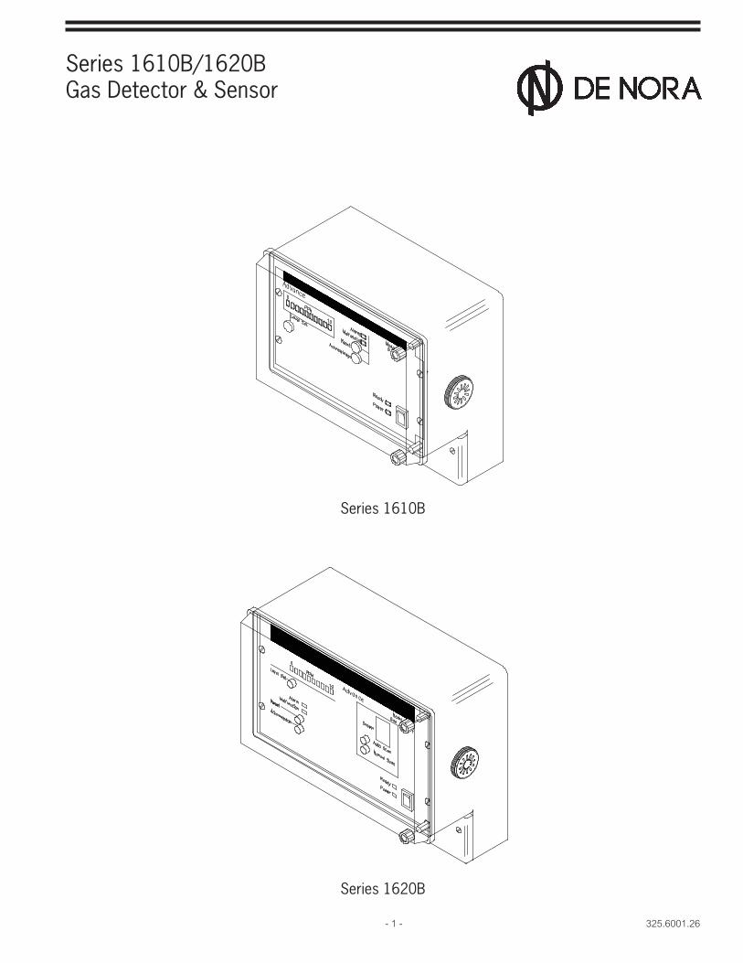
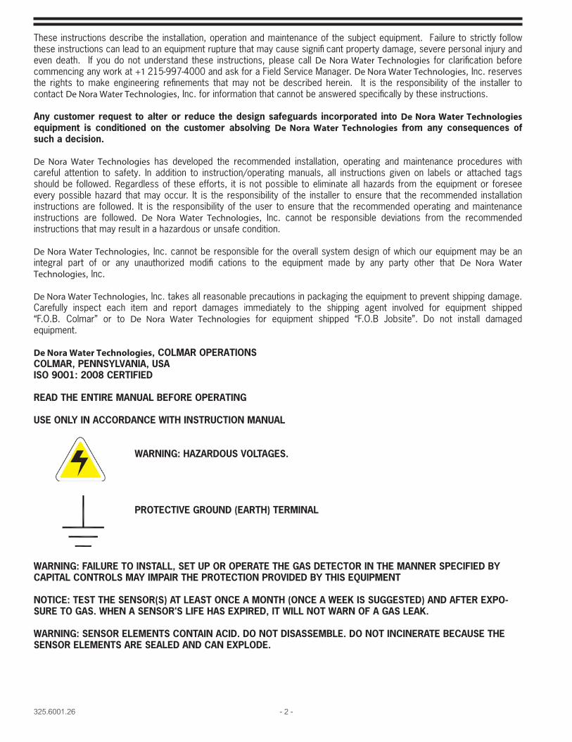
Series 1610B/1620BGas Detector & Sensor
Series 1610B
Series 1620B
325.6001.26 - 2 -
These instructions describe the installation, operation and maintenance of the subject equipment. Failure to strictly follow these instructions can lead to an equipment rupture that may cause signifi cant property damage, severe personal injury and even death. If you do not understand these instructions, please call De Nora Water Technologies for clarification before commencing any work at +1 215-997-4000 and ask for a Field Service Manager. De Nora Water Technologies, Inc. reserves the rights to make engineering refinements that may not be described herein. It is the responsibility of the installer to contact De Nora Water Technologies, Inc. for information that cannot be answered specifically by these instructions.
Any customer request to alter or reduce the design safeguards incorporated into De Nora Water Technologies equipment is conditioned on the customer absolving De Nora Water Technologies from any consequences of such a decision.
De Nora Water Technologies has developed the recommended installation, operating and maintenance procedures with careful attention to safety. In addition to instruction/operating manuals, all instructions given on labels or attached tags should be followed. Regardless of these efforts, it is not possible to eliminate all hazards from the equipment or foresee every possible hazard that may occur. It is the responsibility of the installer to ensure that the recommended installation instructions are followed. It is the responsibility of the user to ensure that the recommended operating and maintenance instructions are followed. De Nora Water Technologies, Inc. cannot be responsible deviations from the recommended instructions that may result in a hazardous or unsafe condition.
De Nora Water Technologies, Inc. cannot be responsible for the overall system design of which our equipment may be an integral part of or any unauthorized modifi cations to the equipment made by any party other that De Nora Water Technologies, Inc.
De Nora Water Technologies, Inc. takes all reasonable precautions in packaging the equipment to prevent shipping damage. Carefully inspect each item and report damages immediately to the shipping agent involved for equipment shipped “F.O.B. Colmar” or to De Nora Water Technologies for equipment shipped “F.O.B Jobsite”. Do not install damaged equipment.
De Nora Water Technologies, COLMAR OPERATIONSCOLMAR, PENNSYLVANIA, USAISO 9001: 2008 CERTIFIED
READ THE ENTIRE MANUAL BEFORE OPERATING
USE ONLY IN ACCORDANCE WITH INSTRUCTION MANUAL
WARNING: HAZARDOUS VOLTAGES.
PROTECTIVE GROUND (EARTH) TERMINAL
WARNING: FAILURE TO INSTALL, SET UP OR OPERATE THE GAS DETECTOR IN THE MANNER SPECIFIED BY CAPITAL CONTROLS MAY IMPAIR THE PROTECTION PROVIDED BY THIS EQUIPMENT
NOTICE: TEST THE SENSOR(S) AT LEAST ONCE A MONTH (ONCE A WEEK IS SUGGESTED) AND AFTER EXPO-SURE TO GAS. WHEN A SENSOR'S LIFE HAS EXPIRED, IT WILL NOT WARN OF A GAS LEAK.
WARNING: SENSOR ELEMENTS CONTAIN ACID. DO NOT DISASSEMBLE. DO NOT INCINERATE BECAUSE THE SENSOR ELEMENTS ARE SEALED AND CAN EXPLODE.
- 3 - 325.6001.26
Table Of Contents
SAFETY ................................................................................................................... 41 INTRODUCTION ........................................................................................................ 5
1.1 General .............................................................................................................................................51.2 Specifi cations .....................................................................................................................................61.3 Quick Start-up .....................................................................................................................................7
2 INSTALLATION ......................................................................................................... 92.1 Mounting ............................................................................................................................................9
2.1.1 Receiver.................................................................................................................................92.1.2 Sensor ...................................................................................................................................9
2.2 Electrical Connections .........................................................................................................................92.2.1 Terminal Access .....................................................................................................................92.2.2 Line Power .............................................................................................................................92.2.3 Malfunction and Alarm Relays ................................................................................................132.2.4 Sensors ...............................................................................................................................152.2.5 Remote 4-20 mAdc and Remote Alarm Outputs .......................................................................16
3 OPERATION .......................................................................................................... 163.1 Start-up ...........................................................................................................................................163.2 Gas Detector System Check ..............................................................................................................18
3.2.1 LED Indicator Functions ........................................................................................................ 183.2.2 Alarm Circuit ........................................................................................................................183.2.3 Malfunction Circuit ................................................................................................................183.2.4 Acknowledgment and Reset .................................................................................................. 183.2.5 System Test ........................................................................................................................ 19
3.3 Sensor Module Setup and Calibration .................................................................................................203.3.1 Set up ..................................................................................................................................203.3.2 Calibration source .................................................................................................................203.3.3 Zero adjustment ...................................................................................................................213.3.4 Sensitivity check ...................................................................................................................213.3.5 Span adjustment ...................................................................................................................213.3.6 Remove voltmeter connections ..............................................................................................21
4 SERVICE ................................................................................................................ 224.1 Sensor Shunt ....................................................................................................................................22 4.2 Sensor Voltage Check ......................................................................................................................224.3 Sensor Element Replacement .............................................................................................................23
5 TROUBLESHOOTING CHART ................................................................................... 266 APPENDIX .......................................................................................................... 27
Series 1610B EC Declaration of Conformity .....................................................................................................28Series 1620B EC Declaration of Conformity .....................................................................................................29
FIGURES1 Series 1610B Receiver Mounting Dimensions ......................................................................................102 Series 1620B Receiver Mounting Dimensions ......................................................................................113 Sensor Mounting Dimensions .............................................................................................................124 Model 1610B Back Printed Circuit Board ............................................................................................125 Model 1620B Back Printed Circuit Board ............................................................................................136 Sensor Printed Circuit Board ..............................................................................................................157 Model 1610B Front Printed Circuit Board ............................................................................................168 Model 1620B Front Printed Circuit Board ............................................................................................179 Sensor Test Method ..........................................................................................................................2010 Shunt Wiring .....................................................................................................................................2311 Sensor Module Assembly ..............................................................................................................24,25
325.6001.26 - 4 -
SAFETYThe recommended operating procedures have been designed with careful attention to safety. De Nora Water Technologies has made formal safety reviews of the initial design and any subsequent changes. This procedure is followed for all new products and covers areas in addition to those included in applicable safety standards. Regardless of these efforts, it is not possible to eliminate all hazards from the equipment or to foresee every possible hazard which may occur. Safety is the responsibility of the user.
This equipment has been designed in accordance with safety specifi cation IEC 1010-1 and ANSI/ISA S82.01 and meets the requirements for Class 1, Installation Category III equipment.Observe the following precautions:
Observe all safety warnings marked on the equipment. These warnings identify areas of immediate hazard which could result in personal injury or loss of life.Do not use this equipment for any purpose other than described in this instruction manual.Disconnect power to the equipment prior to removing the lower access cover plate and making connections to the wiring terminals.
Do not operate the equipment with the lower access cover plate removed. Operation without the lower access cover plate presents an electrical shock hazard.Use all practical safety precautions to prevent contact with energized parts of the equipment and related circuits.
Sensor contains acid, do not disassemble. Do not incinerate; sensor is sealed and may explode.Test each sensor at least once a month (once a week is suggested) and after exposure to a gas leak. When a sensor's life has expired, it will not respond to testing.
Use the recommended connection procedures described elsewhere in this manual.This equipment operates from a single phase power source. It requires a three-wire power cord. The voltage to ground from either pole of the power source must not exceed the maximum rated operating voltage, 240 Vac. Before making connection to the power source, determine that the voltage of the power source is correct. The power source must have a high rupture fuse or circuit breaker rated no higher than 15 amps.
De Nora Water Technologies recommends that qualifi ed personnel install and connect this equipment. Component replacement and internal adjustments must be made by qualifi ed service personnel. The following warning and caution notices are used in this manual where applicable and should be strictly observed.
WARNINGWarning, as used in this manual, is defi ned as a condition or practice which could
result in personal injury or loss of life.
CAUTIONCaution, as used in this manual, is defi ned as a condition or practice which could
result in damage to or destruction of this equipment.
- 5 - 325.6001.26
1 INTRODUCTION
1.1 General
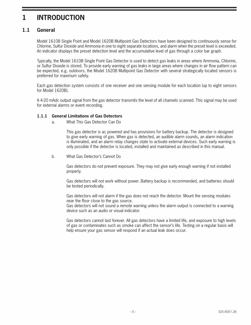
Model 1610B Single Point and Model 1620B Multipoint Gas Detectors have been designed to continuously sense for Chlorine, Sulfur Dioxide and Ammonia in one to eight separate locations, and alarm when the preset level is exceeded. An indicator displays the preset detection level and the accumulative level of gas through a color bar graph.
Typically, the Model 1610B Single Point Gas Detector is used to detect gas leaks in areas where Ammonia, Chlorine, or Sulfur Dioxide is stored. To provide early warning of gas leaks in large areas where changes in air fl ow pattern can be expected, e.g. outdoors, the Model 1620B Multipoint Gas Detector with several strategically located sensors is preferred for maximum safety.
Each gas detection system consists of one receiver and one sensing module for each location (up to eight sensors for Model 1620B).
A 4-20 mAdc output signal from the gas detector transmits the level of all channels scanned. This signal may be used for external alarms or event recording.
1.1.1 General Limitations of Gas Detectors a. What This Gas Detector Can Do
This gas detector is ac powered and has provisions for battery backup. The detector is designed to give early warning of gas. When gas is detected, an audible alarm sounds, an alarm indication is illuminated, and an alarm relay changes state to activate external devices. Such early warning is only possible if the detector is located, installed and maintained as described in this manual.
b. What Gas Detector’s Cannot Do
Gas detectors do not prevent exposure. They may not give early enough warning if not installed properly.
Gas detectors will not work without power. Battery backup is recommended, and batteries should be tested periodically.
Gas detectors will not alarm if the gas does not reach the detector. Mount the sensing modules near the fl oor close to the gas source.Gas detectors will not sound a remote warning unless the alarm output is connected to a warning device such as an audio or visual indicator.
Gas detectors cannot last forever. All gas detectors have a limited life, and exposure to high levels of gas or contaminates such as smoke can affect the sensor’s life. Testing on a regular basis will help ensure your gas sensor will respond if an actual leak does occur.
325.6001.26 - 6 -
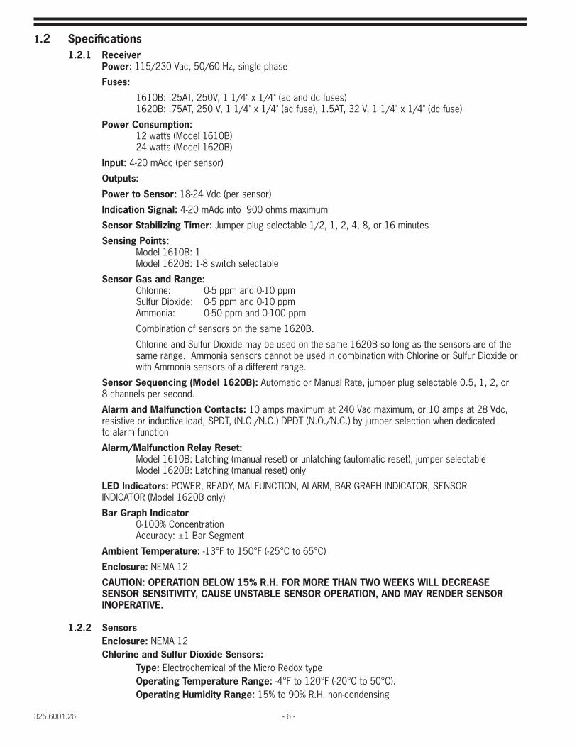
1.2 Specifi cations 1.2.1 Receiver Power: 115/230 Vac, 50/60 Hz, single phase
Fuses:
1610B: .25AT, 250V, 1 1/4" x 1/4" (ac and dc fuses) 1620B: .75AT, 250 V, 1 1/4" x 1/4" (ac fuse), 1.5AT, 32 V, 1 1/4" x 1/4" (dc fuse)
Power Consumption: 12 watts (Model 1610B) 24 watts (Model 1620B)
Input: 4-20 mAdc (per sensor)
Outputs:
Power to Sensor: 18-24 Vdc (per sensor)
Indication Signal: 4-20 mAdc into 900 ohms maximum
Sensor Stabilizing Timer: Jumper plug selectable 1/2, 1, 2, 4, 8, or 16 minutes
Sensing Points: Model 1610B: 1 Model 1620B: 1-8 switch selectable
Sensor Gas and Range: Chlorine: 0-5 ppm and 0-10 ppm Sulfur Dioxide: 0-5 ppm and 0-10 ppm Ammonia: 0-50 ppm and 0-100 ppm
Combination of sensors on the same 1620B.
Chlorine and Sulfur Dioxide may be used on the same 1620B so long as the sensors are of the same range. Ammonia sensors cannot be used in combination with Chlorine or Sulfur Dioxide or with Ammonia sensors of a different range.
Sensor Sequencing (Model 1620B): Automatic or Manual Rate, jumper plug selectable 0.5, 1, 2, or 8 channels per second.
Alarm and Malfunction Contacts: 10 amps maximum at 240 Vac maximum, or 10 amps at 28 Vdc, resistive or inductive load, SPDT, (N.O./N.C.) DPDT (N.O./N.C.) by jumper selection when dedicated to alarm function
Alarm/Malfunction Relay Reset: Model 1610B: Latching (manual reset) or unlatching (automatic reset), jumper selectable Model 1620B: Latching (manual reset) only
LED Indicators: POWER, READY, MALFUNCTION, ALARM, BAR GRAPH INDICATOR, SENSOR INDICATOR (Model 1620B only)
Bar Graph Indicator 0-100% Concentration Accuracy: ±1 Bar Segment
Ambient Temperature: -13°F to 150°F (-25°C to 65°C)
Enclosure: NEMA 12
CAUTION: OPERATION BELOW 15% R.H. FOR MORE THAN TWO WEEKS WILL DECREASE SENSOR SENSITIVITY, CAUSE UNSTABLE SENSOR OPERATION, AND MAY RENDER SENSOR INOPERATIVE.
1.2.2 Sensors Enclosure: NEMA 12 Chlorine and Sulfur Dioxide Sensors: Type: Electrochemical of the Micro Redox type Operating Temperature Range: -4°F to 120°F (-20°C to 50°C). Operating Humidity Range: 15% to 90% R.H. non-condensing
- 7 - 325.6001.26
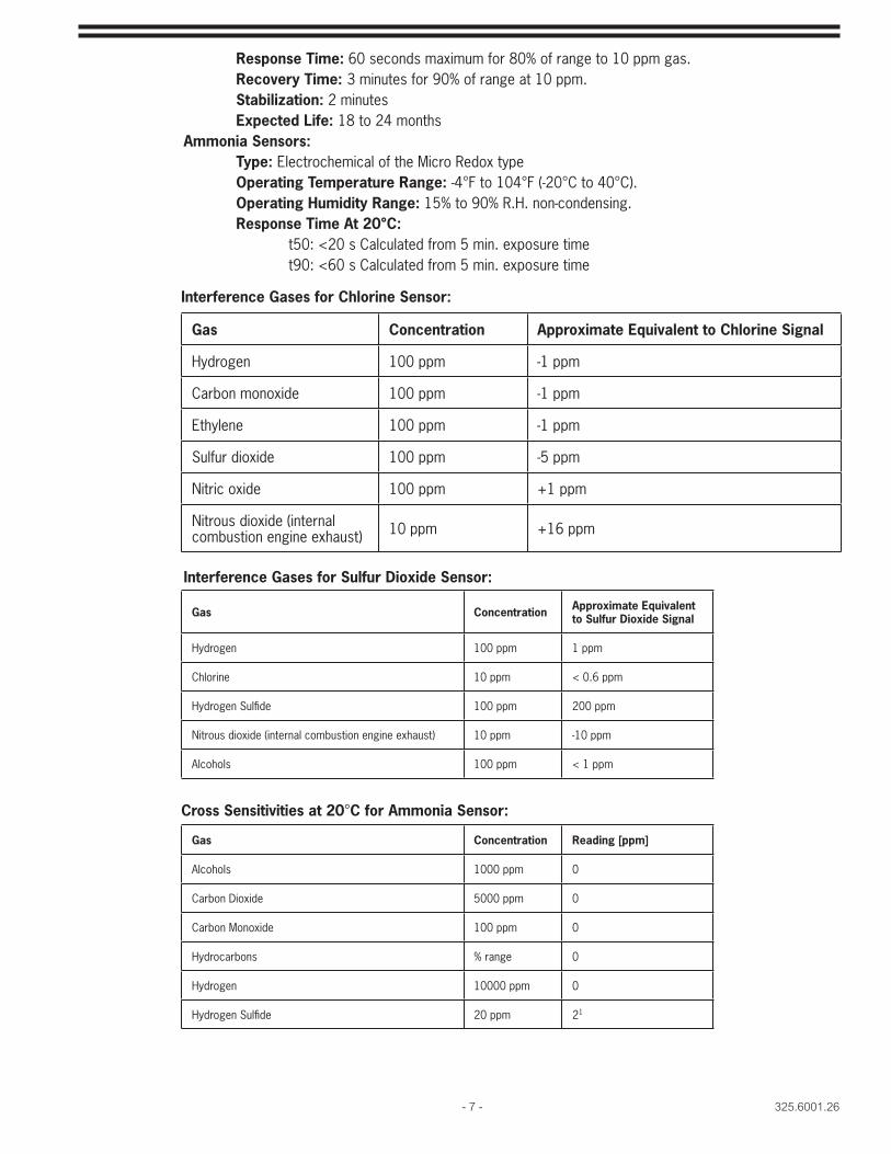
Response Time: 60 seconds maximum for 80% of range to 10 ppm gas. Recovery Time: 3 minutes for 90% of range at 10 ppm. Stabilization: 2 minutes Expected Life: 18 to 24 months Ammonia Sensors: Type: Electrochemical of the Micro Redox type Operating Temperature Range: -4°F to 104°F (-20°C to 40°C). Operating Humidity Range: 15% to 90% R.H. non-condensing. Response Time At 20°C: t50: <20 s Calculated from 5 min. exposure time t90: <60 s Calculated from 5 min. exposure time
Interference Gases for Sulfur Dioxide Sensor:
Gas Concentration Approximate Equivalent to Chlorine Signal
Hydrogen 100 ppm -1 ppm
Carbon monoxide 100 ppm -1 ppm
Ethylene 100 ppm -1 ppm
Sulfur dioxide 100 ppm -5 ppm
Nitric oxide 100 ppm +1 ppm
Nitrous dioxide (internal combustion engine exhaust) 10 ppm +16 ppm
Gas Concentration Reading [ppm]
Alcohols 1000 ppm 0
Carbon Dioxide 5000 ppm 0
Carbon Monoxide 100 ppm 0
Hydrocarbons % range 0
Hydrogen 10000 ppm 0
Hydrogen Sulfi de 20 ppm 21
Gas Concentration Approximate Equivalent to Sulfur Dioxide Signal
Hydrogen 100 ppm 1 ppm
Chlorine 10 ppm < 0.6 ppm
Hydrogen Sulfi de 100 ppm 200 ppm
Nitrous dioxide (internal combustion engine exhaust) 10 ppm -10 ppm
Alcohols 100 ppm < 1 ppm
Interference Gases for Chlorine Sensor:
Cross Sensitivities at 20°C for Ammonia Sensor:
325.6001.26 - 8 -
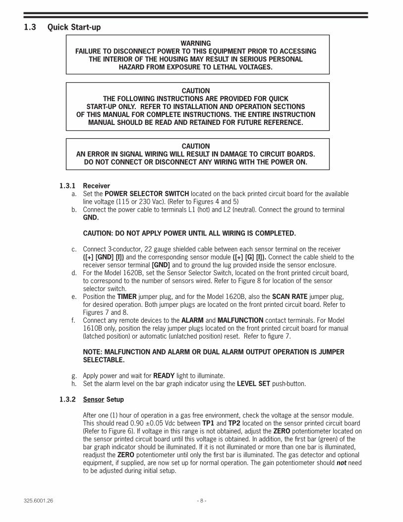
1.3 Quick Start-up
WARNINGFAILURE TO DISCONNECT POWER TO THIS EQUIPMENT PRIOR TO ACCESSING
THE INTERIOR OF THE HOUSING MAY RESULT IN SERIOUS PERSONAL HAZARD FROM EXPOSURE TO LETHAL VOLTAGES.
CAUTIONTHE FOLLOWING INSTRUCTIONS ARE PROVIDED FOR QUICK
START-UP ONLY. REFER TO INSTALLATION AND OPERATION SECTIONS OF THIS MANUAL FOR COMPLETE INSTRUCTIONS. THE ENTIRE INSTRUCTION
MANUAL SHOULD BE READ AND RETAINED FOR FUTURE REFERENCE.
CAUTIONAN ERROR IN SIGNAL WIRING WILL RESULT IN DAMAGE TO CIRCUIT BOARDS.
DO NOT CONNECT OR DISCONNECT ANY WIRING WITH THE POWER ON.
1.3.1 Receivera. Set the POWER SELECTOR SWITCH located on the back printed circuit board for the available
line voltage (115 or 230 Vac). (Refer to Figures 4 and 5)b. Connect the power cable to terminals L1 (hot) and L2 (neutral). Connect the ground to terminal
GND.
CAUTION: DO NOT APPLY POWER UNTIL ALL WIRING IS COMPLETED.
c. Connect 3-conductor, 22 gauge shielded cable between each sensor terminal on the receiver([+] [GND] [I]) and the corresponding sensor module ([+] [G] [I]). Connect the cable shield to thereceiver sensor terminal [GND] and to ground the lug provided inside the sensor enclosure.
d. For the Model 1620B, set the Sensor Selector Switch, located on the front printed circuit board,to correspond to the number of sensors wired. Refer to Figure 8 for location of the sensor
selector switch.e. Position the TIMER jumper plug, and for the Model 1620B, also the SCAN RATE jumper plug,
for desired operation. Both jumper plugs are located on the front printed circuit board. Refer toFigures 7 and 8.
f. Connect any remote devices to the ALARM and MALFUNCTION contact terminals. For Model1610B only, position the relay jumper plugs located on the front printed circuit board for manual(latched position) or automatic (unlatched position) reset. Refer to fi gure 7.
NOTE: MALFUNCTION AND ALARM OR DUAL ALARM OUTPUT OPERATION IS JUMPER SELECTABLE.
g. Apply power and wait for READY light to illuminate.h. Set the alarm level on the bar graph indicator using the LEVEL SET push-button.
1.3.2 Sensor Setup
After one (1) hour of operation in a gas free environment, check the voltage at the sensor module. This should read 0.90 ±0.05 Vdc between TP1 and TP2 located on the sensor printed circuit board (Refer to Figure 6). If voltage in this range is not obtained, adjust the ZERO potentiometer located on the sensor printed circuit board until this voltage is obtained. In addition, the fi rst bar (green) of the bar graph indicator should be illuminated. If it is not illuminated or more than one bar is illuminated, readjust the ZERO potentiometer until only the fi rst bar is illuminated. The gas detector and optional equipment, if supplied, are now set up for normal operation. The gain potentiometer should not need to be adjusted during initial setup.
- 9 - 325.6001.26
2 INSTALLATION
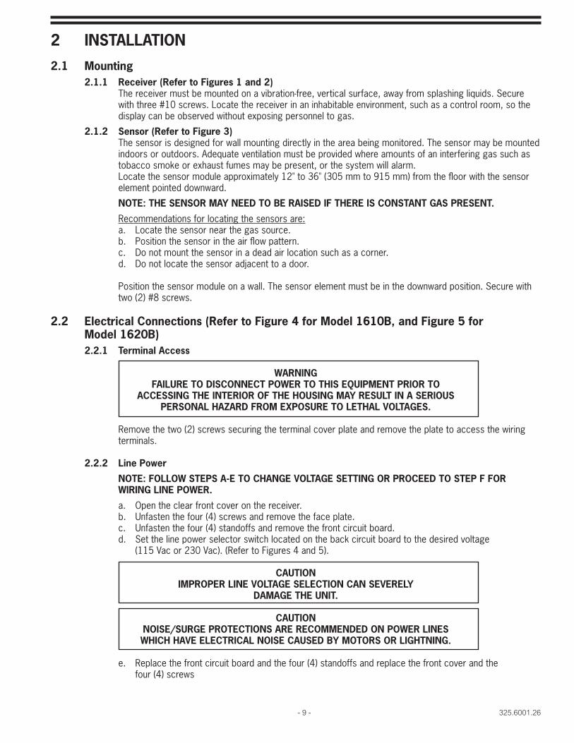
2.1 Mounting2.1.1 Receiver (Refer to Figures 1 and 2)
The receiver must be mounted on a vibration-free, vertical surface, away from splashing liquids. Secure with three #10 screws. Locate the receiver in an inhabitable environment, such as a control room, so the display can be observed without exposing personnel to gas.
2.1.2 Sensor (Refer to Figure 3)The sensor is designed for wall mounting directly in the area being monitored. The sensor may be mounted indoors or outdoors. Adequate ventilation must be provided where amounts of an interfering gas such as tobacco smoke or exhaust fumes may be present, or the system will alarm.Locate the sensor module approximately 12" to 36" (305 mm to 915 mm) from the fl oor with the sensor element pointed downward.
NOTE: THE SENSOR MAY NEED TO BE RAISED IF THERE IS CONSTANT GAS PRESENT.
Recommendations for locating the sensors are:a. Locate the sensor near the gas source.b. Position the sensor in the air fl ow pattern.c. Do not mount the sensor in a dead air location such as a corner.d. Do not locate the sensor adjacent to a door.
Position the sensor module on a wall. The sensor element must be in the downward position. Secure with two (2) #8 screws.
2.2 Electrical Connections (Refer to Figure 4 for Model 1610B, and Figure 5 for Model 1620B)
2.2.1 Terminal Access
WARNINGFAILURE TO DISCONNECT POWER TO THIS EQUIPMENT PRIOR TO
ACCESSING THE INTERIOR OF THE HOUSING MAY RESULT IN A SERIOUS PERSONAL HAZARD FROM EXPOSURE TO LETHAL VOLTAGES.
Remove the two (2) screws securing the terminal cover plate and remove the plate to access the wiring terminals.
2.2.2 Line Power
NOTE: FOLLOW STEPS A-E TO CHANGE VOLTAGE SETTING OR PROCEED TO STEP F FOR WIRING LINE POWER.
a. Open the clear front cover on the receiver.b. Unfasten the four (4) screws and remove the face plate.c. Unfasten the four (4) standoffs and remove the front circuit board.d. Set the line power selector switch located on the back circuit board to the desired voltage
(115 Vac or 230 Vac). (Refer to Figures 4 and 5).
CAUTIONIMPROPER LINE VOLTAGE SELECTION CAN SEVERELY
DAMAGE THE UNIT.
CAUTIONNOISE/SURGE PROTECTIONS ARE RECOMMENDED ON POWER LINES WHICH HAVE ELECTRICAL NOISE CAUSED BY MOTORS OR LIGHTNING.
e. Replace the front circuit board and the four (4) standoffs and replace the front cover and thefour (4) screws

325.6001.26 - 10 -
Figure 1 - Series 1610B Receiver Mounting Dimensions

- 11 - 325.6001.26
Figure 2 - Series 1620B Receiver Mounting Dimensions
325.6001.26 - 12 -
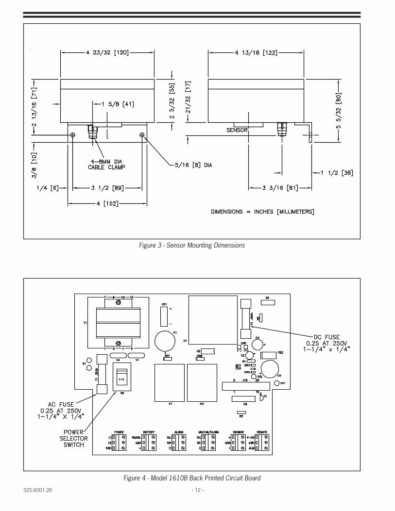
Figure 3 - Sensor Mounting Dimensions
Figure 4 - Model 1610B Back Printed Circuit Board
- 13 - 325.6001.26
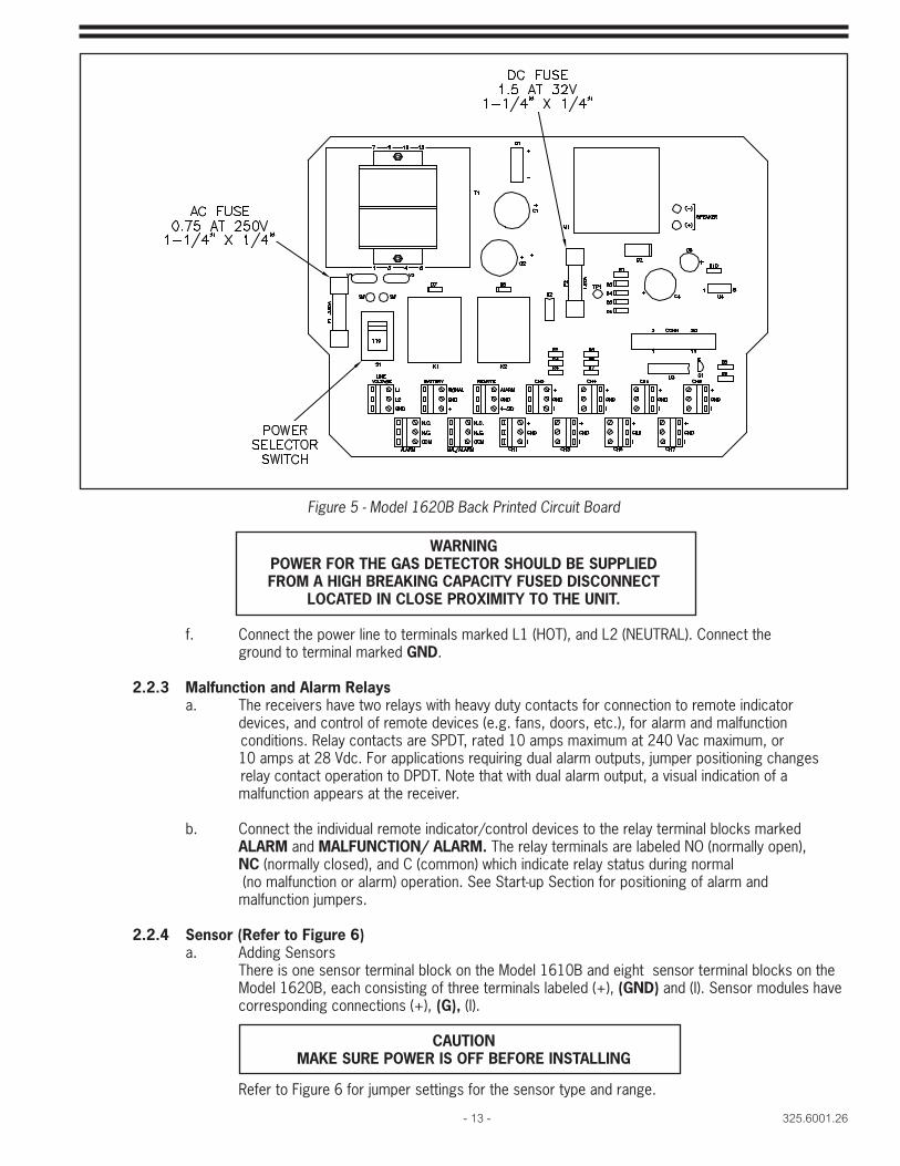
Figure 5 - Model 1620B Back Printed Circuit Board
WARNINGPOWER FOR THE GAS DETECTOR SHOULD BE SUPPLIED FROM A HIGH BREAKING CAPACITY FUSED DISCONNECT
LOCATED IN CLOSE PROXIMITY TO THE UNIT.
f. Connect the power line to terminals marked L1 (HOT), and L2 (NEUTRAL). Connect the ground to terminal marked GND.
2.2.3 Malfunction and Alarm Relays a. The receivers have two relays with heavy duty contacts for connection to remote indicator devices, and control of remote devices (e.g. fans, doors, etc.), for alarm and malfunction conditions. Relay contacts are SPDT, rated 10 amps maximum at 240 Vac maximum, or 10 amps at 28 Vdc. For applications requiring dual alarm outputs, jumper positioning changes relay contact operation to DPDT. Note that with dual alarm output, a visual indication of a malfunction appears at the receiver.
b. Connect the individual remote indicator/control devices to the relay terminal blocks marked ALARM and MALFUNCTION/ ALARM. The relay terminals are labeled NO (normally open), NC (normally closed), and C (common) which indicate relay status during normal (no malfunction or alarm) operation. See Start-up Section for positioning of alarm and malfunction jumpers.
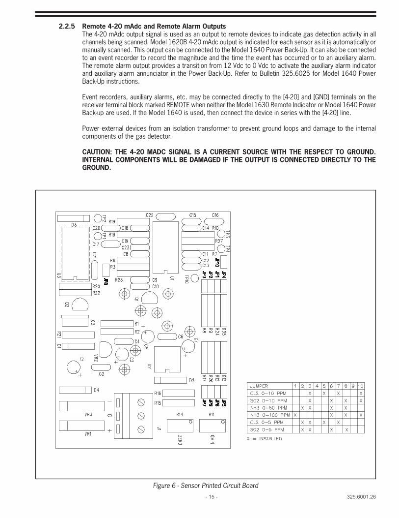
2.2.4 Sensor (Refer to Figure 6) a. Adding Sensors
There is one sensor terminal block on the Model 1610B and eight sensor terminal blocks on the Model 1620B, each consisting of three terminals labeled (+), (GND) and (I). Sensor modules have corresponding connections (+), (G), (I).
CAUTIONMAKE SURE POWER IS OFF BEFORE INSTALLING
Refer to Figure 6 for jumper settings for the sensor type and range.
325.6001.26 - 14 -
1. Loosen the four (4) screws and remove the sensor module cover.2. Sensor connection to the receiver is made using a maximum length of 1,000 feet (305m)
shielded, 3-conductor cable no smaller than 22 gauge. Model 1620B sensors should bewired in consecutive order and their locations recorded in the Appendix section. Apply labelsto faceplate for the gas and range of the sensor connected.
3. Loosen the sensor cable fi tting and feed the cable through the fi tting and around theprinted circuit board, leaving enough slack to fasten each wire to a terminal. Strip thethree (3) wires. For outdoor locations, apply silicone sealant to the cable at the fi tting.
4. Connect the shield to the receiver ground [GND] and to the ground lug located inside the sensor module.5. Connect the positive lead from the receiver to the terminal labeled [+] on the sensor.6. Connect the ground lead from the receiver to the corresponding terminal labeled [G] on
the sensor printed circuit board.7. Connect the current lead from the receiver labeled [I] to the corresponding terminal
labeled [I] on the sensor printed circuit board.
CAUTIONIF ANY OTHER WIRING COMBINATION IS USED, DAMAGE TO THE
SENSOR MODULE WILL RESULT.
8. Replace the sensor module cover and secure with the four (4) screws.9. Tighten the gland fi tting around the cable by making hand-tight, then tighten with a
wrench 1 turn.
CAUTIONINCOMPLETE TIGHTENING OF THE CABLE FITTING AND COVER
SCREWS CAN ALLOW WATER TO ENTER THE ELECTRONICS MODULE WHICH WILL RESULT IN ERRATIC OPERATION.
10. When connecting sensors to the Model 1620B, use a small, thin blade screwdriver to setselector switch located on the front printed circuit board and labeled (S6), to correspondto the number of sensors wired. Do not use positions 0 or 9. (See Figure 8)
11. To add one or more sensors, at a later date to the Model 1620B, connect the sensor(s)as described, increase the sensor selector switch (S6) setting to correspond to the totalnumber of sensors connected to the receiver, and record the new sensor location(s) inthe Appendix. Apply labels to the faceplate for the gas of the sensor added.
b. Removing Model 1620B SensorsThere are two methods that can be used when removing sensors connected to the Model 1620B.Method 1 generally applies when one or more sensors are temporarily removed, e.g. for servicing,and will be reinstalled. Method 2 is recommended when one or more sensors are no longer requiredand are permanently removed.
1. Method 1
With the power to the receiver and all associated equipment TURNED OFF, disconnect the wires from the sensor module and replace with a sensor shunt (Part Number A-1119). Refer to SERVICE SECTION for the procedure. This method will allow the circuit to be scanned and monitored as operating normally. Reapply power to the receiver and all associated equipment following shunt installation.
2. Method 2
With the power to the receiver and all associated equipment TURNED OFF, disconnect the sensor being removed from the receiver. Then disconnect the sensor located in the last position and reconnect it in the position previously occupied by the removed sensor. Finally, decrease the sensor selector switch (S6) position by one (Refer to Figure 8), and record the removal of one sensor and the new position of the repositioned sensor in the Appendix. Change faceplate labels as required. Reapply power to the receiver and associated equipment.
- 15 - 325.6001.26
2.2.5 Remote 4-20 mAdc and Remote Alarm OutputsThe 4-20 mAdc output signal is used as an output to remote devices to indicate gas detection activity in all channels being scanned. Model 1620B 4-20 mAdc output is indicated for each sensor as it is automatically or manually scanned. This output can be connected to the Model 1640 Power Back-Up. It can also be connected to an event recorder to record the magnitude and the time the event has occurred or to an auxiliary alarm. The remote alarm output provides a transition from 12 Vdc to 0 Vdc to activate the auxiliary alarm indicator and auxiliary alarm annunciator in the Power Back-Up. Refer to Bulletin 325.6025 for Model 1640 Power Back-Up instructions.
Event recorders, auxiliary alarms, etc. may be connected directly to the [4-20] and [GND] terminals on the receiver terminal block marked REMOTE when neither the Model 1630 Remote Indicator or Model 1640 Power Back-up are used. If the Model 1640 is used, then connect the device in series with the [4-20] line.
Power external devices from an isolation transformer to prevent ground loops and damage to the internal components of the gas detector.
CAUTION: THE 4-20 MADC SIGNAL IS A CURRENT SOURCE WITH THE RESPECT TO GROUND. INTERNAL COMPONENTS WILL BE DAMAGED IF THE OUTPUT IS CONNECTED DIRECTLY TO THE GROUND.
Figure 6 - Sensor Printed Circuit Board
325.6001.26 - 16 -
3 OPERATION
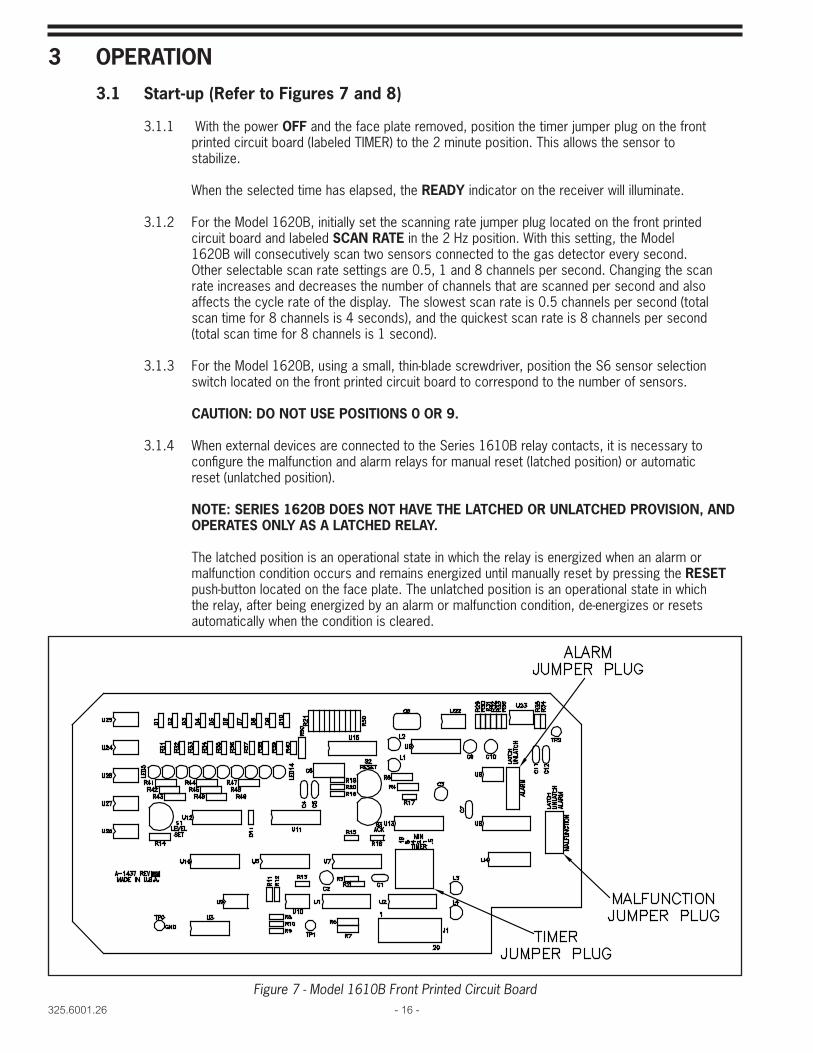
3.1 Start-up (Refer to Figures 7 and 8)
3.1.1 With the power OFF and the face plate removed, position the timer jumper plug on the front printed circuit board (labeled TIMER) to the 2 minute position. This allows the sensor to stabilize.
When the selected time has elapsed, the READY indicator on the receiver will illuminate.
3.1.2 For the Model 1620B, initially set the scanning rate jumper plug located on the front printed circuit board and labeled SCAN RATE in the 2 Hz position. With this setting, the Model 1620B will consecutively scan two sensors connected to the gas detector every second. Other selectable scan rate settings are 0.5, 1 and 8 channels per second. Changing the scan rate increases and decreases the number of channels that are scanned per second and also affects the cycle rate of the display. The slowest scan rate is 0.5 channels per second (total scan time for 8 channels is 4 seconds), and the quickest scan rate is 8 channels per second (total scan time for 8 channels is 1 second).
3.1.3 For the Model 1620B, using a small, thin-blade screwdriver, position the S6 sensor selection switch located on the front printed circuit board to correspond to the number of sensors.
CAUTION: DO NOT USE POSITIONS 0 OR 9.
3.1.4 When external devices are connected to the Series 1610B relay contacts, it is necessary to confi gure the malfunction and alarm relays for manual reset (latched position) or automatic reset (unlatched position).
NOTE: SERIES 1620B DOES NOT HAVE THE LATCHED OR UNLATCHED PROVISION, AND OPERATES ONLY AS A LATCHED RELAY.
The latched position is an operational state in which the relay is energized when an alarm or malfunction condition occurs and remains energized until manually reset by pressing the RESET push-button located on the face plate. The unlatched position is an operational state in which the relay, after being energized by an alarm or malfunction condition, de-energizes or resets automatically when the condition is cleared.
Figure 7 - Model 1610B Front Printed Circuit Board

- 17 - 325.6001.26
a. For malfunction and alarm relay outputs from the Model 1610B, place the jumper plugs on the connectors labeled MALFUNCTION and ALARM and located on the front printed circuit board in the LATCH (Manual reset) or UNLATCH (automatic reset) position. b. For malfunction and alarm relay outputs from the Model 1620B, position the jumper plugs on the connector marked MALFUNCTION and ALARM and located on the front printed circuit board to the MALFUNCTION position. Note that the Model 1620B is designed for manual reset only. 3.1.5 For applications requiring dual alarm relay outputs, the receiver can be confi gured for DPDT operation. a. For dual alarm relay outputs from Model 1610B, position the jumper plug on the connector labeled MALFUNCTION to the ALARM position. Then place the jumper plug on the connector labeled ALARM, to the LATCH (manual reset) or UNLATCH (automatic reset) position. b. For dual alarm relay outputs from the Model 1620B, position the jumper plug on the connectors marked MALFUNCTION and ALARM to the ALARM position.
3.1.6 Replace the face plate and secure with the four (4) screws.
3.1.7 Turn the power switch to the ON position. Power can be verifi ed by the illuminated POWER indicator on the face plate of the gas detector. If either the ac or dc fuse is blown, the POWER indicator will not illuminate.
3.1.8 The fl ashing bar graph segment indicates the level set point. Set the level of sensitivity using the LEVEL SET push button on the face of the receiver. Depress once for each increasing level. To decrease the level, continue to depress the button until the highest value is reached. Depress the button again, and the indicator will return to its lowest position. Continue depressing until the desired value is obtained.
Figure 8 - Model 1620B Front Printed Circuit Board
325.6001.26 - 18 -
NOTE: THE ALARM LEVEL SETTING IS UNAFFECTED FOR UP TO 48 HOURS BY A POWER OUTAGE AND, FOR INSTALLATIONS WITH NO POWER BACK-UP, WILL RETURN TO THE PRE-OUTAGE SETTING WHEN POWER TO THE GAS DETECTOR IS REESTABLISHED.
3.1.9. For Model 1620B, select either MANUAL or AUTOMATIC SCANNING by depressing either the AUTO or MANUAL SCAN button one (1) time.
To select the sensor to be scanned in the MANUAL mode, depress the MANUAL SCAN button until the desired sensor number appears on the sensor indicator. The sensors appear in descending order (highest to lowest).
3.1.10 When the READY indicator is illuminated on the face plate of the receiver, the sensors have stabilizedand normal operation has begun. The fi rst bar (green) bar on the indicator must be illuminated to indicate operative sensor circuitry. If no bar is illuminated or more than one bar is illuminated, the sensor(s) require adjustment. Refer to Sensor Module Setup Section.
3.1.11 Close and secure the front cover of the receiver ensuring a tight seal.
3.2 Gas Detector System Check
3.2.1 LED Indicator Functionsa. POWER - Power applied and fuses are good.b. READY - Sensors are ready.c. MALFUNCTION - A sensor has malfunctioned.d. ALARM - Gas is present.e. BAR GRAPH - Indicates the absence or presence of gas.
3.2.2 Alarm CircuitIn the presence of gas, the sensor transmits an increasing 4-20 mAdc signal. This increasing signal is displayed by accumulated bar segments on the indicator. The signal is electronically compared to the preset level and, when exceeded, the alarm circuit is activated, the relay contact closes, the ALARM indicator will illuminate, and the annunciator will sound. This occurs with each channel in an ALARM state with the Model 1620B Multipoint Gas Detector (when in the AUTO SCAN mode).
3.2.3 Malfunction Circuit
If the 4-20 mAdc signal is not maintained, the malfunction circuit will activate. This can be caused by misadjustment of the sensor’s zero voltage, loss of dc voltage to the sensor, or an open wire in the sensor cable. This will illuminate the MALFUNCTION indicator and the fi rst bar on the bar graph indicator will not be illuminated. This occurs with each channel in the MALFUNCTION state with the Model 1620B Multipoint Gas Detector (when in the AUTO SCAN mode).
3.2.4 Acknowledgment and Reset
The ALARM indicator will illuminate and the annunciator will sound whenever the preset level is exceeded. The annunciator will continue to sound until the ACKNOWLEDGE push-button is depressed (depressing the RESET push-button WILL NOT turn off the annunciator). Should the alarm condition persist after manual reset, the ALARM indicator will remain illuminated and the annunciator will sound again.When a sensor is in either ALARM or MALFUNCTION, and the corresponding relay jumper is in the LATCHED (manual reset) position, that sensor cannot resume normal operation until the condition is corrected and the RESET button is depressed. If the corresponding relay jumper is in the UNLATCHED (automatic reset) position, automatic reset will occur when the condition is corrected.If the sensor has alarmed due to the presence of gas, the gas must be evacuated and the sensor allowed to clear and stabilize. This may take as long as 3-5 minutes depending upon the concentration of the gas and the length of exposure.

- 19 - 325.6001.26
3.2.5 System Test
WARNINGTEST THE SENSORS AT LEAST ONCE A MONTH (ONCE A WEEK IS SUGGESTED) A ND AFTER EXPOSURE TO GAS. WHEN A SENSOR’S LIFE HAS EXPIRED, IT WILL
NOT WARN OF A GAS LEAK.
WARNINGSENSOR ELEMENTS CONTAIN ACID. DO NOT DISASSEMBLE. DO NOT INCINERATE
BECAUSE THE SENSOR IS SEALED AND CAN EXPLODE.
CAUTIONOPERATION BELOW 15% R.H. FOR MORE THAN TWO (2) WEEKS WILL DECREASE
SENSOR SENSITIVITY, CAUSE UNSTABLE SENSOR OPERATION, AND MAY RENDER SENSOR INOPERATIVE.
CAUTIONEXPOSURE OF THE SENSOR TO SOLVENT VAPORS, SUCH AS ACETONE
AND ALCOHOL WILL MAKE IT TEMPORARILY INSENSITIVE.
Ammonia Sensors can be periodically tested using part number 23357. Refer to instructions supplied with the kit for proper testing procedure. Calibration cup assembly 26402 should be used with span gas for calibration.
Chlorine or Sulfur Dioxide sensors can be periodically tested using part number BM-4709.
Test Kit produces small quantities of Chlorine or Sulfur Dioxide gas in a concentration of approximately 50 ppm (parts per million).
a. Kit Contents1. Instructions2. Chlorinated Concentrate (99% Sodium Dichloro-s-triazinetrione, 55% available
Chlorine).
NOTE: THIS PRODUCT IS AVAILABLE FROM POOL CHEMICAL SUPPLY STORES AND IS USED FOR HOT TUB/SPA CHLORINATION.
3. Sodium metabisulfi te tablets.4. Boric acid5. 140 ml plastic squeeze bottle.6. 5 ml measuring spoon.7. Gas dispenser or Calibration Cap.8. Tubing
NOTE: DISCONNECT EXTERNAL ALARMS BEFORE PROCEEDING WITH SYSTEM TESTING.
b. 1. Set the alarm level at the front panel of the Model 1610B or 1620B Receiver to the maximum value. On the Model 1620B, pressthe MANUAL SCAN button until the sensor to be tested is indicated.
2. If the receiver cannot be seen from the sensor location, have another person at thereceiver, and a means of communications (e.g. telephone) available to relayinformation.
3. Place ½ spoonful of boric acid into the plastic bottle using the 5 ml measuringspoon.
4. Place two (2) spoonfuls of water into the plastic bottle.5. To generate Chlorine, place one (1) spoonful of the chlorinated concentrate into the
bottle using the 5 ml spoon. Carefully shake the bottle to mix.
OR
To generate Sulfur Dioxide, repeat steps 3 and 4 above, then place one (1) sodium metabisulfi te tablet into the bottle. Carefully shake the bottle to mix.
6. Tighten the tapered cap on the squeeze bottle, and place the gas dispenser on thesqueeze bottle’s tapered spout. Refer to Figure 9.

325.6001.26 - 20 -
7. Place the dispenser over gas detector sensor. Refer to Figure 9.8. Slowly (15-20 seconds) squeeze the plastic bottle to dispel the gas. The gas detector alarm
should indicate gas presence.9. If the gas detector does not alarm, repeat the gas application. If the detector still does not
alarm, refer to the Gas Detector Troubleshooting Chart section repair procedures.10. Reconnect external alarms.11. Dispose of the squeeze bottle contents by fl ushing down the drain with cold water. Do not
store mixed chemicals.12. Make a permanent record of the test results in the back of this document.
Figure 9 - System Test Method
3.3 Sensor Module Calibration3.3.1 Set up
The following is equipment is required for calibration:DC VoltmeterSmall thin bladed screwdriverCalibration source
3.3.2 Calibration sourceA variety of sources may be used for sensor calibration including:- Cylinder gas- Portable gas generators- Permeation devices
Portable gas generators are available from De Nora Water Technologies. Consult De Nora Water Technologies or your local representative for information. For cylinder gases please contact a specialty gas supplier for further information.
For proper delivery of calibration gas to the sensor the following calibration cap assemblies are required:- Chlorine and Sulfur Dioxide Part Number 27643- Ammonia Part Number 26402
Gas is delivered to the sensor from the source using tubing made of inert materials, Tefl on is preferred but polyurethane is acceptable. The tubing should be ¼ inch OD in order to fi t properly in the calibration cap.
For gas delivery to the sensor, the tubing is inserted into the ¼ inch hole in the calibration cap which attaches to the bottom of the sensor assembly. The fl ow rate for the calibrated gas source required is 500 mL/min. When calibration is complete the calibration cap should be removed for normal gas sensing operation.

- 21 - 325.6001.26
3.3.3 Zero Adjustment:
3.3.3.1 With the sensor connected to the receiver, apply power and allow the system to stabilize for one hour in a chlorine free environment.
CAUTIONTHIS SENSOR MODULE HAS BEEN SET AT THE FACTORY USING
AN ACCURATE GAS SUPPLY. CHANGING THE SETTINGS CAN MODIFY THE ACCURACY OF THE SYSTEM. ADJUSTMENT MAY BE NECESSARY AS THE SENSOR AGES. CHECK CALIBRATION VOLTAGES EVERY THREE MONTHS.
3.3.3.2 Remove the sensor module cover. Connect a DC voltmeter to the sensor module, the ground test lead to test point 1 (TP1) and the positive lead to test point 2 (TP2) (refer to fi gure 6). The volt meter should read 0.9 volts +/- 0.05 volts.
3.3.3.3 If adjustment is required, turn the zero potentiometer until 0.9 volts +/- 0.05 volts is achieved.
3.3.4 Sensitivity check: Connect a dc voltmeter between TP1 and TP2. Verify that the 0.90 Vdc signal is present across the test points. Expose the sensor to the appropriate gas source calibrated for the range of the sensor under test. The voltage reading should go from 0.90 Vdc to 4.0 Vdc in 60 seconds. If the 4.0 Vdc level is achieved the sensitivity of the element is considered good, proceed with the span adjustment.
If the 4.0 Vdc measurement is not achieved, complete the span adjustment as described below. After span is complete allow the sensor to sit in chlorine free air for 5 minutes to clear out any residual chlorine. Next, run the sensitivity check again. If the 4.0 Vdc reading is not achieved in 60 seconds then replace the sensor element.
3.3.5 Span adjustment: Connect a dc voltmeter between TP1 and TP2. Expose the sensor to the appropriate gas source calibrated for the proper sensor range. Allow the sensor voltage reading to stabilize; this should take between two and three minutes. Once stable, adjust the gain potentiometer on the sensor board for 5.0 Vdc +/- .05 Vdc.
3.3.6 Remove voltmeter connections and replace sensor module cover.
325.6001.26 - 22 -
4 SERVICENOTE: DUE TO THE NATURE OF THIS EQUIPMENT AND THE USE OF CUSTOM-BUILT ELEMENTS, IT IS RECOMMENDED THAT THIS EQUIPMENT BE RETURNED TO THE FACTORY FOR REPAIR OR REPLACEMENT IF FOUND TO BE DEFECTIVE IN FORM OR FUNCTION.
4.1 Sensor Shunt (Model 1620B only - Part Number A-1119) (Refer to Figure 10)A shunt is used as a substitute for a sensor module by imitating a clean air signal. This will enable sensor module removal without interrupting the scanning capability of the gas detector.
4.1.1 Turn OFF power at the gas detector.
4.1.2 Remove the four (4) screws and the cover on the sensor module.
4.1.3 Remove the sensor module from its wall mounting.
4.1.4 Disconnect all wires and remove the cable.
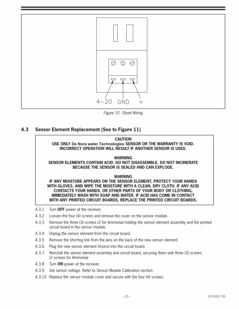
4.1.5 Connect the shunt to the receiver as follows:
Receiver Shunt
(+) to (+)
(GND) to (GND)
(I) to (4-20)
4.1.6 Turn ON power at the gas detector.
4.1.7 Continue normal operation of the gas detector.
4.2 Sensor Voltage Check To determine the correct action required for an inoperative Sensor, use a voltmeter to perform the following voltage checks. Refer to Figures 4.5.6.
4.2.1 Check the voltage between TP1 and TP2. If the Voltage is approximately .9 Volts DC proceed to step 4.2.6
4.2.2 If no Voltage is present move to the next step.
4.2.3 Check the Voltage between the Sensor Cable (+) and (GND) at the Receiver end. If the measured voltage is 18-24 Volts DC proceed to step 4.2.5. If no Voltage is present proceed to the next step.
4.2.4 Check the fuse on the main Receiver Power Board. This will be the lower board in the Receiver. If the fuse is good, replace the main power board. If the fuse is blown, replace the fuse and repeat the above steps.
4.2.5 Check the voltage between the (+) and (GND) on the Sensor Board. If the voltage is 18-24 Volts DC replace the Sensor Board. If the voltage is not present replace the sensor cable and repeat the above steps.
4.2.6 Adjust the voltage between TP1 and TP2 for 0.90 Volts +/-0.05 Volts DC with the ZERO potentiometer. See Figure 6. Proceed to next step.
4.2.7 Connect the voltmeter to TP1 and TP2. Generate and expose the sensor element to test gas described in Section 3.3 Sensor Calibration. If the voltage between TP1 and TP2 does change when the sensor is exposed to the test gas, proceed to the step 4.2.8. If the voltage does not change when exposed to test gas, replace the sensor and repeat the above steps.
4.2.8 Check the voltage between TP1 and (I) terminal on the Sensor Bd. If the voltage does not change when the sensor is exposed to the test gas replace the sensor and printed circuit board.
- 23 - 325.6001.26
4.3 Sensor Element Replacement (See to Figure 11)
CAUTIONUSE ONLY De Nora water Technologies SENSOR OR THE WARRANTY IS VOID.
INCORRECT OPERATION WILL RESULT IF ANOTHER SENSOR IS USED.
WARNINGSENSOR ELEMENTS CONTAIN ACID. DO NOT DISASSEMBLE. DO NOT INCINERATE
BECAUSE THE SENSOR IS SEALED AND CAN EXPLODE.
WARNINGIF ANY MOISTURE APPEARS ON THE SENSOR ELEMENT, PROTECT YOUR HANDS
WITH GLOVES, AND WIPE THE MOISTURE WITH A CLEAN, DRY CLOTH. IF ANY ACID CONTACTS YOUR HANDS, OR OTHER PARTS OF YOUR BODY OR CLOTHING,
IMMEDIATELY WASH WITH SOAP AND WATER. IF ACID HAS COME IN CONTACT WITH ANY PRINTED CIRCUIT BOARDS, REPLACE THE PRINTED CIRCUIT BOARDS.
4.3.1 Turn OFF power at the receiver.
4.3.2 Loosen the four (4) screws and remove the cover on the sensor module.
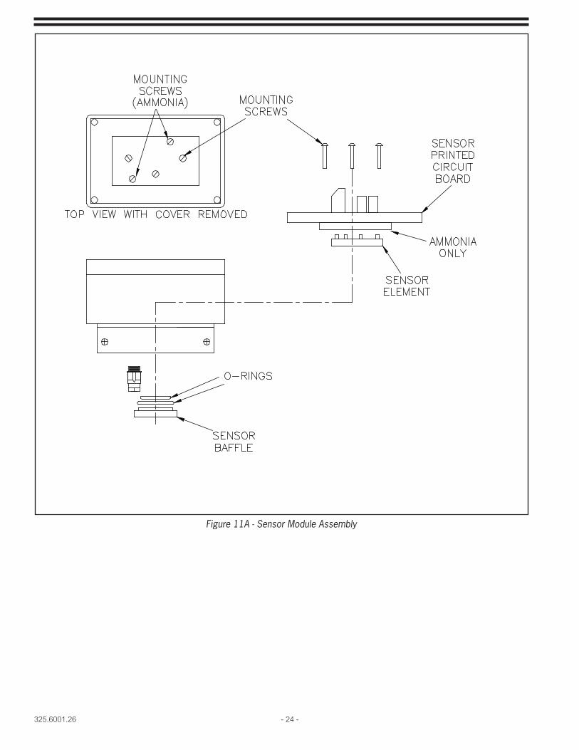
4.3.3 Remove the three (3) screws (2 for Ammonia) holding the sensor element assembly and the printed circuit board in the sensor module.
4.3.4 Unplug the sensor element from the circuit board.
4.3.5 Remove the shorting link from the pins on the back of the new sensor element.
4.3.6 Plug the new sensor element (4-pins) into the circuit board.
4.3.7 Reinstall the sensor element assembly and circuit board, securing them with three (3) screws. (2 screws for Ammonia)
4.3.8 Turn ON power at the receiver.
4.3.9 Set sensor voltage. Refer to Sensor Module Calibration section.
4.3.10 Replace the sensor module cover and secure with the four (4) screws.
Figure 10 - Shunt Wiring
325.6001.26 - 24 -
Figure 11A - Sensor Module Assembly
- 25 - 325.6001.26
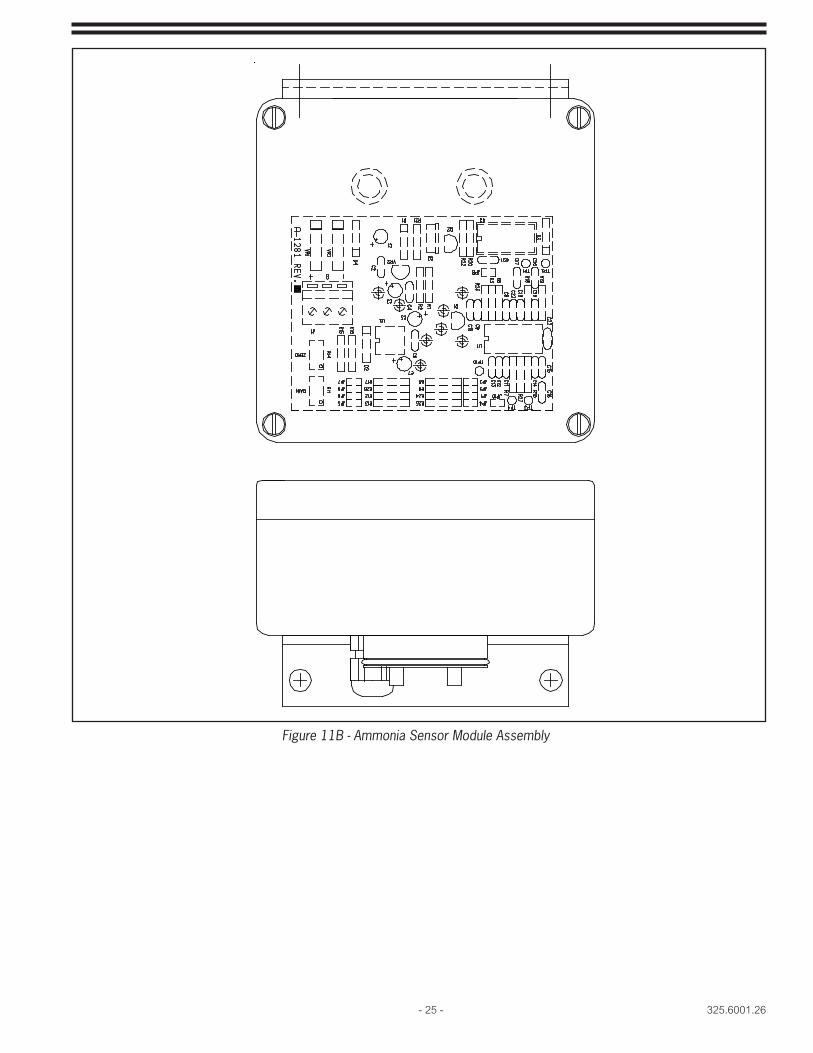
Figure 11B - Ammonia Sensor Module Assembly
325.6001.26 - 26 -
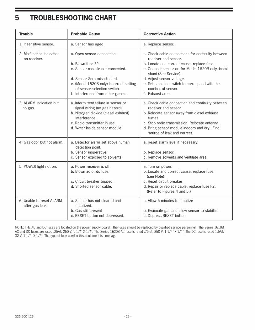
5 TROUBLESHOOTING CHART
NOTE: THE AC and DC fuses are located on the power supply board. The fuses should be replaced by qualifi ed service personnel. The Series 1610B AC and DC fuses are rated .25AT, 250 V, 1 1/4" X 1/4". The Series 1620B AC fuse is rated .75 at, 250 V, 1 1/4" X 1/4"; The DC fuse is rated 1.5AT, 32 V, 1 1/4" X 1/4". The type of fuse used in this equipment is time lag.
Trouble Probable Cause Corrective Action
1. Insensitive sensor. a. Sensor has aged a. Replace sensor.
2. Malfunction indicationon receiver.
a. Open sensor connection.
b. Blown fuse F2c. Sensor module not connected.
d. Sensor Zero misadjusted.e. (Model 1620B only) Incorrect setting
of sensor selection switch.f. Interference from other gases.
a. Check cable connections for continuity betweenreceiver and sensor.
b. Locate and correct cause, replace fuse.c. Connect sensor or, for Model 1620B only, install
shunt (See Service).d. Adjust sensor voltage.e. Set selection switch to correspond with the
number of sensor.f. Exhaust area.
3. ALARM indication butno gas
a. Intermittent failure in sensor orsignal wiring (no gas hazard)
b. Nitrogen dioxide (diesel exhaust)interference.
c. Radio transmitter in use.d. Water inside sensor module.
a. Check cable connection and continuity betweenreceiver and sensor.
b. Relocate sensor away from diesel exhaustfumes.
c. Stop radio transmission. Relocate antenna.d. Bring sensor module indoors and dry. Find
source of leak and correct.
4. Gas odor but not alarm. a. Detector alarm set above humandetection point.
b. Sensor inoperative.c. Sensor exposed to solvents.
a. Reset alarm level if necessary.
b. Replace sensor.c. Remove solvents and ventilate area.
5. POWER light not on. a. Power receiver is off.b. Blown ac or dc fuse.
c. Circuit breaker tripped.d. Shorted sensor cable.
a. Turn on power.b. Locate and correct cause, replace fuse.
(see Note)c. Reset circuit breakerd. Repair or replace cable, replace fuse F2.
(Refer to Figures 4 and 5.)
6. Unable to reset ALARMafter gas leak.
a. Sensor has not cleared andstabilized.
b. Gas still presentc. RESET button not depressed.
a. Allow 5 minutes to stabilize
b. Evacuate gas and allow sensor to stabilize.c. Depress RESET button.
- 27 - 325.6001.26
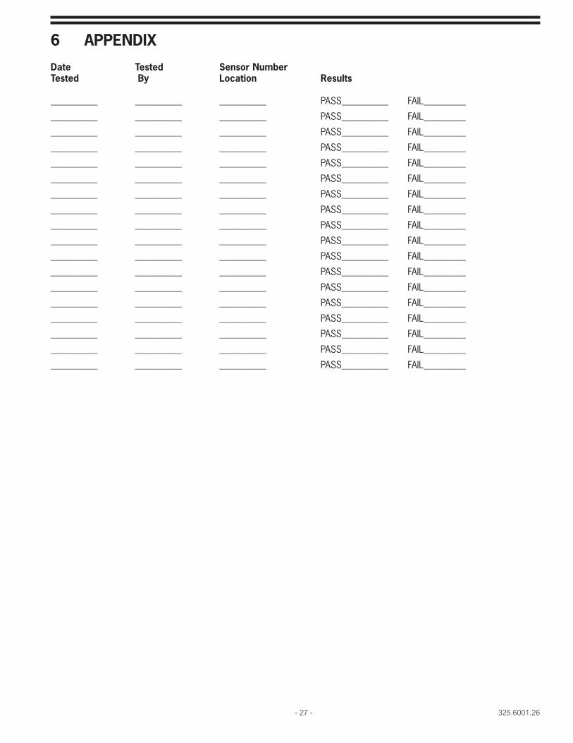
6 APPENDIX
Date Tested Sensor NumberTested By Location Results
__________ __________ __________ PASS__________ FAIL_________
__________ __________ __________ PASS__________ FAIL_________
__________ __________ __________ PASS__________ FAIL_________
__________ __________ __________ PASS__________ FAIL_________
__________ __________ __________ PASS__________ FAIL_________
__________ __________ __________ PASS__________ FAIL_________
__________ __________ __________ PASS__________ FAIL_________
__________ __________ __________ PASS__________ FAIL_________
__________ __________ __________ PASS__________ FAIL_________
__________ __________ __________ PASS__________ FAIL_________
__________ __________ __________ PASS__________ FAIL_________
__________ __________ __________ PASS__________ FAIL_________
__________ __________ __________ PASS__________ FAIL_________
__________ __________ __________ PASS__________ FAIL_________
__________ __________ __________ PASS__________ FAIL_________
__________ __________ __________ PASS__________ FAIL_________
__________ __________ __________ PASS__________ FAIL_________
__________ __________ __________ PASS__________ FAIL_________

325.6001.26 - 28 -
THIS PAGE INTENTIONALLY LEFT BLANK

- 29 - 325.6001.26
325.6001.26 - 30 -
Represented by:
Design improvements may be made without notice.
De Nora Water Technologies3000 Advance Lane Colmar, PA 18915 ph +1 215 997 4000 • fax +1 215 997 4062 web: www.denora.commail: [email protected]
®Registered Trademark. © 2015. All Rights Reserved.SEP 2015