series 8 c300 controller - honeywell · 2018-07-17 · r500 series april 2017 8 c300 controller...
TRANSCRIPT
Honeywell Process Solutions
Series 8
C300 Controller
User's Guide
EXDOC-XX11-en-500A
R500
April 2017
Release 500
Honeywell
2 Series 8 C300 Controller User's Guide Honeywell
R500 April 2017
Notices and Trademarks
Copyright 2017 by Honeywell International Sárl. Release 500 April 2017
While this information is presented in good faith and believed to be accurate, Honeywell disclaims the implied warranties of merchantability and fitness for a particular purpose and makes no express warranties except as may be stated in its written agreement with and for its customers.
In no event is Honeywell liable to anyone for any indirect, special or consequential damages. The information and specifications in this document are subject to change without notice.
Honeywell, PlantScape, Experion LX™, and TotalPlant are registered trademarks of Honeywell International Inc.
Other brand or product names are trademarks of their respective owners.
Honeywell Process Solutions
1860 W. Rose Garden Lane
Phoenix, AZ 85027 USA
1-800 822-7673
R500 April 2017
Series 8 C300 Controller User's Guide Honeywell
3
About This Document
Provides information that assists you in planning and designing activities, as well as the
installation, operation, and troubleshooting of C300 Process Controllers in Experion LX
system.
Intended audience
This document is intended for the following users:
Persons responsible for system planning, initial hardware installation, and control
strategy configuration.
Operators who help to maintain control system operations on a day-by-day basis.
Service personis responsible for routine maintenance of control hardware and who also diagnose and repair faults.
Prerequisite skills
It is assumed that you should have some knowledge of Experion LX control systems
and experience of working in a Microsoft Windows environment.
Release Information
Document Name Document ID Release Number
Publication Date
C300 Controller User's Guide - ccig CVDOC- XX11-en- 500A
500 April 2017
4 Series 8 C300 Controller User's Guide Honeywell
R500 April 2017
References
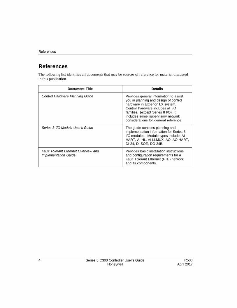
References
The following list identifies all documents that may be sources of reference for material discussed
in this publication.
Document Title Details
Control Hardware Planning Guide Provides general information to assist you in planning and design of control hardware in Experion LX system. Control hardware includes all I/O families, (except Series 8 I/O). It includes some supervisory network considerations for general reference.
Series 8 I/O Module User's Guide The guide contains planning and implementation information for Series 8 I/O modules. Module types include: AI- HART, AI-HL, AI-LLMUX, AO, AO-HART, DI-24, DI-SOE, DO-24B.
Fault Tolerant Ethernet Overview and Implementation Guide
Provides basic installation instructions and configuration requirements for a Fault Tolerant Ethernet (FTE) network and its components.
Support and Other Contacts
R500 April 2017
Series 8 C300 Controller User's Guide Honeywell
5
Support and Other Contacts
People’s Republic of China
Contact: Phone:
Mail:
Email:
Honeywell Global TAC – China +86- 21-2219-6888 800-820-0237 400-820-0386 Honeywell (China) Co., Ltd 33/F, Tower A, City Center, 100 Zunyi Rd. Shanghai 200051, People’s Republic of China [email protected]
6 Series 8 C300 Controller User's Guide Honeywell
R500 April 2017
Symbol Definitions
Symbol Definitions
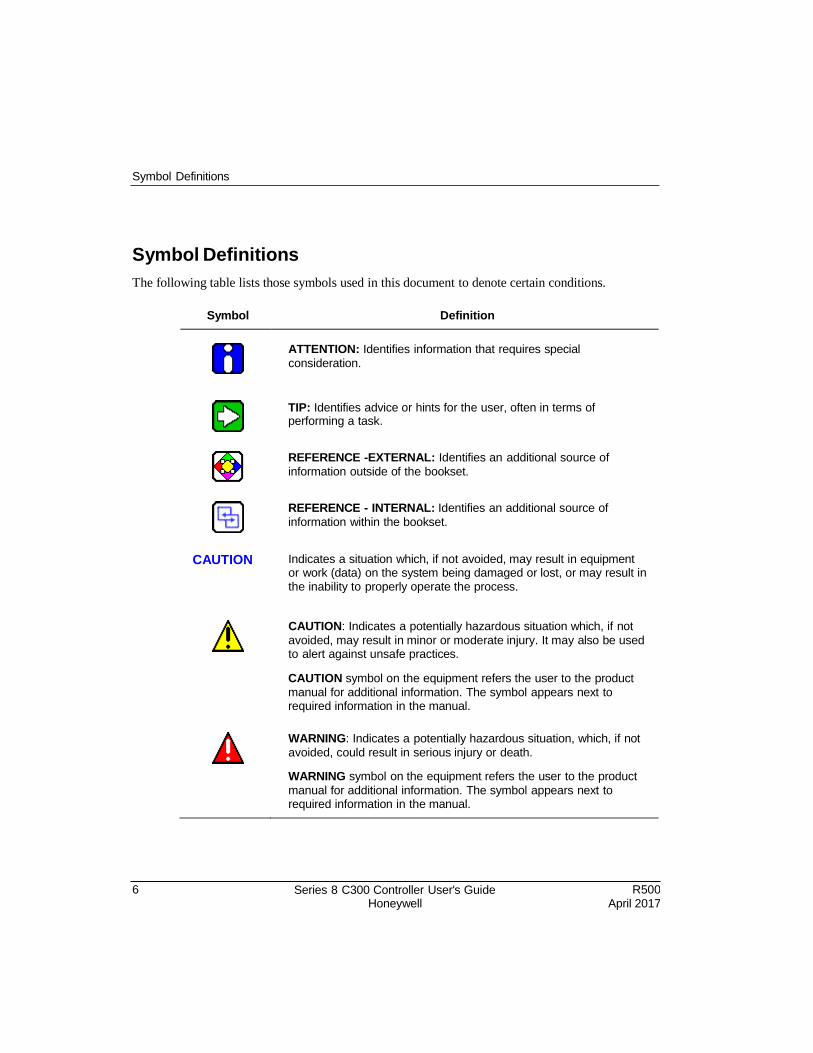
The following table lists those symbols used in this document to denote certain conditions.
Symbol Definition
ATTENTION: Identifies information that requires special
consideration.
TIP: Identifies advice or hints for the user, often in terms of performing a task.
REFERENCE -EXTERNAL: Identifies an additional source of
information outside of the bookset.
REFERENCE - INTERNAL: Identifies an additional source of
information within the bookset.
CAUTION Indicates a situation which, if not avoided, may result in equipment or work (data) on the system being damaged or lost, or may result in the inability to properly operate the process.
CAUTION: Indicates a potentially hazardous situation which, if not
avoided, may result in minor or moderate injury. It may also be used to alert against unsafe practices.
CAUTION symbol on the equipment refers the user to the product
manual for additional information. The symbol appears next to required information in the manual.
WARNING: Indicates a potentially hazardous situation, which, if not
avoided, could result in serious injury or death.
WARNING symbol on the equipment refers the user to the product
manual for additional information. The symbol appears next to required information in the manual.
R500 April 2017
Series 8 C300 Controller User's Guide Honeywell
7
Symbol Definitions
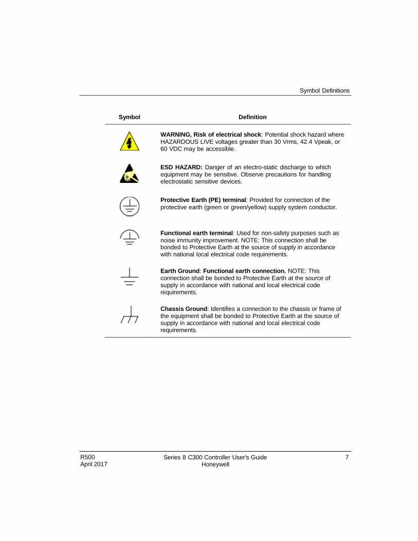
Symbol Definition
WARNING, Risk of electrical shock: Potential shock hazard where
HAZARDOUS LIVE voltages greater than 30 Vrms, 42.4 Vpeak, or 60 VDC may be accessible.
ESD HAZARD: Danger of an electro-static discharge to which
equipment may be sensitive. Observe precautions for handling electrostatic sensitive devices.
Protective Earth (PE) terminal: Provided for connection of the
protective earth (green or green/yellow) supply system conductor.
Functional earth terminal: Used for non-safety purposes such as
noise immunity improvement. NOTE: This connection shall be bonded to Protective Earth at the source of supply in accordance with national local electrical code requirements.
Earth Ground: Functional earth connection. NOTE: This connection shall be bonded to Protective Earth at the source of supply in accordance with national and local electrical code requirements.
Chassis Ground: Identifies a connection to the chassis or frame of the equipment shall be bonded to Protective Earth at the source of supply in accordance with national and local electrical code requirements.

R500 April 2017
Series 8 C300 Controller User's Guide Honeywell
9
Contents
1. C300 CONTROLLER PURPOSE ............................................ 19
1.1 C300 Controller Features ...................................................................... 19
1.1 Getting started ................................................................................................... 20 What task do you want to perform? .......................................................................................... 20
2. C300 CONTROLLER PLANNING AND DESIGN .................. 23
2.1 Review Experion LX system capabilities ............................................... 23
2.2 Control Hardware Planning Guide ....................................................... 24
2.3 Series 8 control hardware ........................................................................ 24 Series C form factor ................................................................................................................... 24
2.4 C300 Controller ...................................................................................... 26 C300 Controller execution environments .................................................................................. 27 I/O modules supported by the C300 Controller ......................................................................... 28
2.5 Identify C300 Controller components .................................................... 28
2.6 Control network considerations ............................................................. 29 C300 Peer communication with Experion LX nodes................................................................. 29
3. C300 CONTROLLER INSTALLATION AND UPGRADES ........... 31
3.1 Pre-installation considerations ............................................................... 31 Installation declarations ............................................................................................................. 31 Series 8 control hardware installation requirements................................................................. 32
3.2 C300 Controller installation .................................................................. 32 C300 Controller assembly ......................................................................................................... 32 C300 Secondary Controller Installation .................................................................................... 37
3.4 Series 8 I/O modules installation ............................................................ 41
3.5 Series 8 FIM Installation ........................................................................... 41
3.6 Upgrading C300 Controller Firmware ..................................................... 41 C300 Controller behavior during firmware upgrade and timeout ............................................. 41
10
Series 8 C300 Controller User's Guide Honeywell
R500 April 2017
4. C300 CONTROLLER CONFIGURATION .............................. 43
4.1 Configuration overview ............................................................................ 44 Configuration Studio ............................................................................................................ 44 Define and add assets in your enterprise model ....................................................................... 44 FTE system configuration .......................................................................................................... 44 Specifying a Time Server ................................................................................................................ 45 C300 Controller Device Index .................................................................................................... 45
4.2 Create C300 Controller and CEE function blocks ............................... 46
4.3 Configure CEEC300 block ........................................................................53
4.4 Configure a Secondary C300 Controller block .....................................58
4.5 Convert a non-redundant C300 Controller to a redundant controller ....... 60
4.6 Convert a redundant C300 Controller to a non-redundant controller ....... 63
4.7 Configure IOLINK function blocks ....................................................... 64
4.8 Import/export C300 Controller configuration ....................................... 67
4.9 Reset Device Index and IP address of a controller ...................................... 67
4.10 Create a Control Module.................................................................... 69
4.11 Assign Control Modules and IOMs to a CEEC300 block ......................... 72
4.12 Copy Control Modules ..........................................................................78
4.13 Assign I/O Modules to C300 IOLINK blocks.......................................80
4.14 Add an I/O Channel to a Control Module ......................................... 84
5. C300 CONFIGURATION FORM REFERENCE ........................... 87
5.1 C300 Controller Block ...............................................................................87 Main tab ............................................................................................................................... 87 Redundancy tab ................................................................................................................... 91 System Time tab ........................................................................................................................ 95
Statistics tab ........................................................................................................................ 96 Peer Connections tab .......................................................................................................... 98 Hardware Information tab ..................................................................................................... 99 FTE tab ..................................................................................................................................... 100 UTP/TCP tab ......................................................................................................................104 IP/ICMP tab ........................................................................................................................106 Soft Failures tab ..................................................................................................................110 Server History tab ...............................................................................................................112
R500 April 2017
Series 8 C300 Controller User's Guide Honeywell
11
Server Displays tab .............................................................................................................114 Control Confirmation tab .......................................................................................................... 116 Identification tab ..................................................................................................................116
5.2 Secondary C300 Block ........................................................................ 118
Main Tab .................................................................................................................................. 118 Redundancy Tab ..................................................................................................................... 118
5.3 CEEC300 Function Block ....................................................................... 119 Main Tab .................................................................................................................................. 119 Peer Configuration tab ........................................................................................................ 122 Statistics tab ....................................................................................................................... 123 CPU Loading Tab .................................................................................................................... 128 CPU Overruns tab ................................................................................................................... 129 Memory tab ........................................................................................................................ 130 Peer Communications tab ....................................................................................................... 132 Exchange Communications tab ........................................................................................... 133 Display Communications tab ............................................................................................... 134 Block Types Info tab ........................................................................................................... 135 CAB Types Info tab ............................................................................................................. 136 Custom Types Info tab ........................................................................................................ 137 Server History tab ............................................................................................................... 138 Server Displays tab ............................................................................................................. 138 Control Confirmation tab .......................................................................................................... 138 Identification tab .................................................................................................................. 138
5.4 IOLINK Block ............................................................................................ 139 Main Tab .................................................................................................................................. 139 Memory Stats tab................................................................................................................ 141 Statistics tab ....................................................................................................................... 143 I/O Link Status tab ................................................................................................................... 150 I/O Status Summary tab ...................................................................................................... 153 IOTA Summary tabs ........................................................................................................... 155 Server History tab ............................................................................................................... 156 Server Displays tab ............................................................................................................. 157 Control Confirmation tab .......................................................................................................... 157
Identification tab .................................................................................................................. 157
6. LOAD C300 CONTROLLER CONFIGURATION ................. 159
6.1 About load operations ........................................................................ 159 Loaded versus project database versions .............................................................................. 159 Load initiation and load dialog box ...................................................................................... 160 Load action with compare parameters function ................................................................... 161 Load options for server history and server displays configuration ......................................... 161
6.2 Initial load order guidelines ................................................................... 162 Component deletion considerations ........................................................................................ 162
12
Series 8 C300 Controller User's Guide Honeywell
R500 April 2017
6.3 Load components from Project .......................................................... 163 Loading C300 Controller.......................................................................................................... 163 Loading IOLINK .................................................................................................................. 165 Loading CEEC300 ................................................................................................................... 167 Loading IOMs and CMs ........................................................................................................... 169
R500 Series 8 C300 Controller User's Guide xi
6.4 Load With Contents command ............................................................. 170
6.5 Reloading components from project ................................................... 170
6.6 Upload to the Monitoring database .................................................... 172
7. C300 CONTROLLER OPERATION ........................................... 173
7.1 C300 Controller start up ...................................................................... 174 C300 Controller states in boot mode ...................................................................................176 C300 Controller states in application mode .........................................................................177
7.2 C300 faceplate indicators/displays ...................................................... 179 Power and Status LEDs ........................................................................................................... 180 Faceplate display information ..............................................................................................181 FTE activity LEDs ..................................................................................................................... 183
7.3 C300 faceplate display indications ...................................................... 184 Controller display during normal operation .............................................................................. 184 Controller display in BOOT mode ........................................................................................185
7.4 Control Builder block icon descriptions............................................ 186
7.5 Activate C300 Controller's CEE .......................................................... 190 Initial activation order guidelines .............................................................................................. 190 Activating the CEE ................................................................................................................... 190 Setting the CEE inactive .......................................................................................................... 191 CEE Icon states in the Monitoring tab .................................................................................192
7.6 Initiating C300 Controller Shutdown ................................................... 193
7.7 Initiating Synchronization command ................................................... 194 Prerequisites ............................................................................................................................ 194
Commanding synchronization ................................................................................................. 194
7.8 Disable Synchronization command ..................................................... 195 Prerequisites ............................................................................................................................ 195
7.9 Initiating Become Primary command .................................................. 196 Prerequisites ............................................................................................................................ 196 Commanding Become Primary ................................................................................................ 196
7.10 Initiating Switchover command ........................................................ 197
R500 April 2017
Series 8 C300 Controller User's Guide Honeywell
13
Prerequisites ............................................................................................................................ 197 Commanding a switchover ....................................................................................................... 197
7.11 Using Station displays ........................................................................198 C300 Controller Point Detail displays ...................................................................................... 198 System Status Display ............................................................................................................. 198 Event and Alarm summary displays ........................................................................................ 198 Controller Detail displays ......................................................................................................... 198
FTE Status display .................................................................................................................. 198
7.12 Viewing controller operation and status in Control Builder ................. 199
7.13 C300 operating behaviors .................................................................. 201 Time management in the C300 Controller .............................................................................. 201 Hardware Watchdog Timer ..................................................................................................... 202
Critical Task Monitor ................................................................................................................ 202
7.14 C300 Controller processing overload behavior ............................. 203 Causes of controller overloading ............................................................................................. 204 How to avoid controller overloading ........................................................................................ 204 Recovery from an overload ..................................................................................................... 205
8. C300 REDUNDANCY OPERATION .................................... 207
8.1 Description ........................................................................................... 207
8.2 Redundancy configuration restrictions ............................................. 208 C300 Controller Device Index.................................................................................................. 208 IOLINK interface considerations .............................................................................................. 208
8.3 Partner (controller) compatibility .......................................................... 208 Redundancy compatibility parameter - RDNCMPT ................................................................ 209
8.4 Synchronization states ........................................................................... 210 Standby state ........................................................................................................................... 211
8.5 Redundancy parameters ........................................................................ 212 Enable Synchronization - ENBLSYNCCMD ........................................................................... 213 Disable Synchronization - DSBLSYNCCMD ........................................................................... 213 Enable Standby - ENBLSTBYCMD ......................................................................................... 213 Auto-Synchronization State - RDNAUTOSYNC ..................................................................... 213 Inhibit Sync Reason - RDNINHIBITSYNC .............................................................................. 214 Initial Sync Progress - RDNSYNCPROG ................................................................................ 215 Maximum Initial Synchronization Time - RDNISTIMEMAX .................................................... 215 Last Synchronization Time - SYNCTIMEBEG ........................................................................ 216 Last Lost of Sync Time - SYNCTIMEEND .............................................................................. 216 Redundancy Traffic ................................................................................................................. 216 Redundancy Delay .................................................................................................................. 216 Conditions that result in loss of sync ....................................................................................... 216 Conditions that do not result in loss of sync ......................................................................... 217
14
Series 8 C300 Controller User's Guide Honeywell
R500 April 2017
8.6 Switchover ........................................................................................... 217 Initiate Switchover - SWITCHCMD ......................................................................................... 217 Max Switchover Time - RDNSOTIMEMAX ............................................................................. 217 Conditions that result in switchover ......................................................................................... 218 Conditions that do not result in a switchover .......................................................................... 218
Become Primary command - BECMPRICMD ......................................................................... 219
8.7 Redundancy history ................................................................................219
8.8 C300 Redundancy-related notifications ............................................ 220 Redundancy Link Status - RDNLINKFAILED .......................................................................... 223
8.9 Controller redundancy specifications ............................................... 223
9. C300 CONTROLLER MAINTENANCE ...................................... 225
9.1 Periodic Checks .......................................................................................225
9.2 Recommended Spare Parts ................................................................ 225
9.3 C300 Controller module and IOTA replacement ............................... 226
10. C300 CONTROLLER TROUBLESHOOTING ............................ 231
10.1 Overview................................................................................................ 231
10.2 What to do when faults occur ......................................................... 232
10.3 Initial checks .........................................................................................232 Checking Control Builder error code reference ....................................................................... 232 Checking faceplate display and LEDs ..................................................................................... 232 Using CTools to capture diagnostic data ................................................................................. 233 Viewing flash log ...................................................................................................................... 234 Viewing release information log ...........................................................................................234 Checking server point build log ...........................................................................................234 Checking server point build error log ...................................................................................234
Checking error log .................................................................................................................... 234
10.4 Fixing common problems ............................................................... 235 Loss of power ........................................................................................................................... 235 Power-On Self Test (POST) does not complete ..................................................................... 235 Controller display shows -bp- or -ts .....................................................................................236 Controller display shows -SF- alternating with OK/BKUP ....................................................... 236 One or both FTE LEDs are RED ............................................................................................. 237 FTE receive fault diagnostic..................................................................................................... 237 Controller does not synchronize with backup .......................................................................... 238
Fatal ECC error .............................................................................................................................. 239 Display shows FAIL ................................................................................................................. 240 Isolated (lonely) Node .............................................................................................................. 240
R500 April 2017
Series 8 C300 Controller User's Guide Honeywell
15
Duplicate Device Index setting ............................................................................................241 Device Index value is zero upon power up ..........................................................................242
10.5 C300 Controller soft failures ............................................................. 243
10.6 IOLINK block soft failures .................................................................. 248
10.7 Additional status and fault messages ............................................. 251
Redundancy-related notifications ............................................................................................ 251
10.8 Online diagnostics .............................................................................. 251
10.9 Fault classifications ......................................................................... 252 Hard/Severe Failures ............................................................................................................... 253 Soft Failures ............................................................................................................................. 254 Installation-Startup Failures ..................................................................................................... 255 Hardware Watchdog Timer Expired ........................................................................................ 255 Communications Failure .......................................................................................................... 256
10.10 Communication and system time faults during startup ....................... 256 Non-redundant C300 Controller with no Memory Retention .................................................. 257 Non-redundant C300 Controller with Memory Retention........................................................ 258 Redundant Primary C300 Controller with no Memory Retention ........................................... 261 Redundant Primary C300 Controller with Memory Retention ................................................ 262 Secondary C300 Controller with no Memory Retention ......................................................... 264 Secondary C300 Controller with Memory Retention .............................................................. 265
10.11 Gathering information for reporting problems to Honeywell ................ 268
10.12 Getting further assistance .................................................................. 270 Other troubleshooting sources ................................................................................................ 270 Guidelines for requesting support ........................................................................................... 270
Contents
16 Series 8 C300 Controller User's Guide Honeywell
R500 April 2017
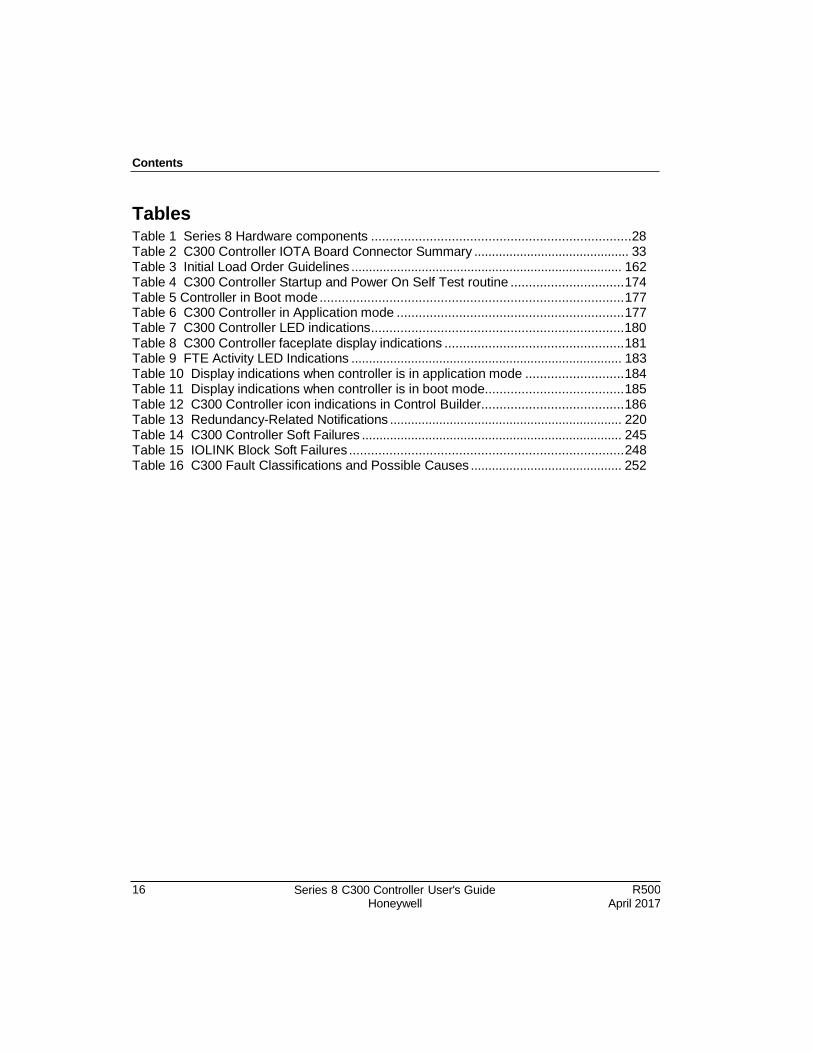
Tables Table 1 Series 8 Hardware components ....................................................................... 28 Table 2 C300 Controller IOTA Board Connector Summary ............................................ 33 Table 3 Initial Load Order Guidelines ............................................................................. 162 Table 4 C300 Controller Startup and Power On Self Test routine ............................... 174 Table 5 Controller in Boot mode ................................................................................... 177 Table 6 C300 Controller in Application mode .............................................................. 177 Table 7 C300 Controller LED indications ..................................................................... 180 Table 8 C300 Controller faceplate display indications ................................................. 181 Table 9 FTE Activity LED Indications ............................................................................. 183 Table 10 Display indications when controller is in application mode ........................... 184 Table 11 Display indications when controller is in boot mode...................................... 185 Table 12 C300 Controller icon indications in Control Builder....................................... 186 Table 13 Redundancy-Related Notifications .................................................................. 220 Table 14 C300 Controller Soft Failures .......................................................................... 245 Table 15 IOLINK Block Soft Failures ........................................................................... 248 Table 16 C300 Fault Classifications and Possible Causes ........................................... 252
Contents
R500 April 2017
Series 8 C300 Controller User's Guide Honeywell
17
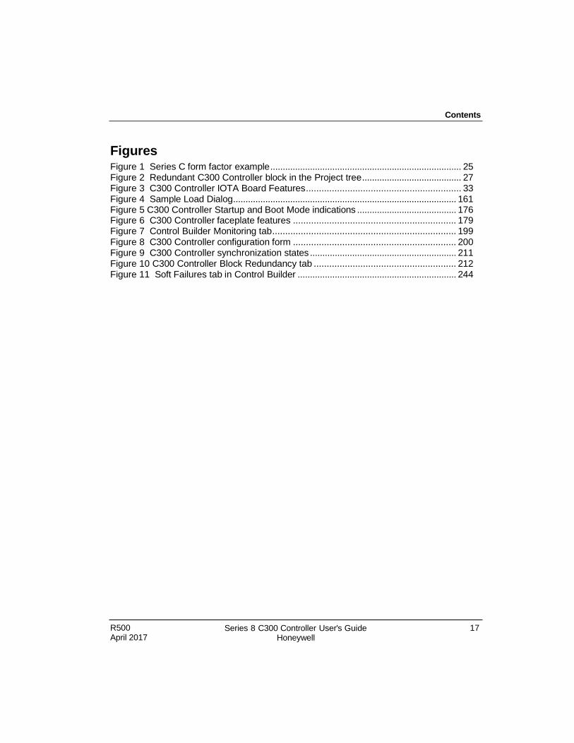
Figures Figure 1 Series C form factor example ............................................................................. 25 Figure 2 Redundant C300 Controller block in the Project tree ........................................ 27 Figure 3 C300 Controller IOTA Board Features ............................................................ 33 Figure 4 Sample Load Dialog .......................................................................................... 161 Figure 5 C300 Controller Startup and Boot Mode indications ........................................ 176 Figure 6 C300 Controller faceplate features ............................................................... 179 Figure 7 Control Builder Monitoring tab ....................................................................... 199 Figure 8 C300 Controller configuration form ............................................................... 200 Figure 9 C300 Controller synchronization states ........................................................... 211 Figure 10 C300 Controller Block Redundancy tab ....................................................... 212 Figure 11 Soft Failures tab in Control Builder ................................................................ 244

R500 April 2017
Series 8 C300 Controller User's Guide Honeywell
19
1. C300 Controller Purpose
This chapter provides the tasks that are related to using the C300 Controller with the
Experion LX system.
The following table provides the sections covered in this chapter. Click the topic to view
it.
1.1 C300 Controller Features
The following table provides the design features and operational improvements of C300
Controller.
Controller Feature Description
Form Factor A single control module that plugs into an Input Output Terminal Assembly (IOTA). Control module functions include a Control processor, two I/O Link interfaces, Redundancy functions, and FTE interfaces.
Memory (RAM) 16MB User Memory.
Redundancy Controller redundancy function is built in. A second C300 Controller and redundancy cable is all that is required for redundant controller operation.
I/O Link Interface Two I/O Link interfaces are built in to the controller. Each I/O Link can connect with Series 8 I/O modules.
Communications Interface to supervisory network
Ethernet interface is built into the controller and supports both Ethernet and redundant FTE communications.
Peer-to-Peer Connections
Ethernet interface is built into the controller to support both Ethernet and redundant FTE communications.
Function Blocks The standard Experion LX function block types for control strategy execution are used.
For more information refer to Series 8 Control Hardware.
Engineering Tools The same engineering tools utilities and applications for
Topic
Getting started task list
20 Series 8 C300 Controller User's Guide Honeywell
R500 April 2017
1. C300 Controller Purpose 1.1. Getting started
Controller Feature Description
maintenance tasks are used. The CTools engineering utility is used to upgrade C300 firmware and extract files containing diagnostic data when troubleshooting problems.
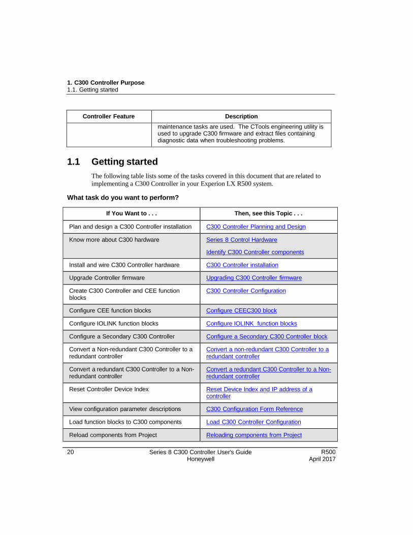
1.1 Getting started
The following table lists some of the tasks covered in this document that are related to
implementing a C300 Controller in your Experion LX R500 system.
What task do you want to perform?
If You Want to . . . Then, see this Topic . . .
Plan and design a C300 Controller installation C300 Controller Planning and Design
Know more about C300 hardware Series 8 Control Hardware
Identify C300 Controller components
Install and wire C300 Controller hardware C300 Controller installation
Upgrade Controller firmware Upgrading C300 Controller firmware
Create C300 Controller and CEE function blocks
C300 Controller Configuration
Configure CEE function blocks Configure CEEC300 block
Configure IOLINK function blocks Configure IOLINK function blocks
Configure a Secondary C300 Controller Configure a Secondary C300 Controller block
Convert a Non-redundant C300 Controller to a redundant controller
Convert a non-redundant C300 Controller to a redundant controller
Convert a redundant C300 Controller to a Non- redundant controller
Convert a redundant C300 Controller to a Non- redundant controller
Reset Controller Device Index Res et Device Index and IP address of a controller
View configuration parameter descriptions C300 Configuration Form Reference
Load function blocks to C300 components Load C300 Controller Configuration
Reload components from Project Reloading components from Project
R500 April 2017
Series 8 C300 Controller User's Guide Honeywell
21
1. C300 Controller Purpose 1.1. Getting started
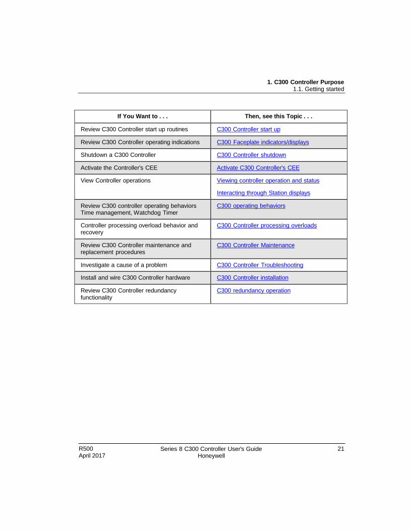
If You Want to . . . Then, see this Topic . . .
Review C300 Controller start up routines C300 Controller start up
Review C300 Controller operating indications C300 Faceplate indicators/displays
Shutdown a C300 Controller C300 Controller shutdown
Activate the Controller's CEE Activate C300 Controller's CEE
View Controller operations Viewing controller operation and status
Interacting through Station displays
Review C300 controller operating behaviors Time management, Watchdog Timer
C300 operating behaviors
Controller processing overload behavior and recovery
C300 Controller processing overloads
Review C300 Controller maintenance and replacement procedures
C300 Controller Maintenance
Investigate a cause of a problem C300 Controller Troubleshooting
Install and wire C300 Controller hardware C300 Controller installation
Review C300 Controller redundancy functionality
C300 redundancy operation

22 Series 8 C300 Controller User's Guide Honeywell
R500 April 2017
1. C300 Controller Purpose 1.1. Getting started
R500 April 2017
Series 8 C300 Controller User's Guide Honeywell
23
2. C300 Controller Planning and Design
This chapter provides information about system planning and design of the C300
Controller. The following table provides the sections covered in this chapter. Click the
topic to view it.
Topic
Review Experion LX system capabilities
Control Hardware Planning Guide
Series 8 control hardware
C300 Controller
Identifying C300 Controller components
Control network considerations
2.1 Review Experion LX system capabilities
For information to the basic concepts and terminology, refer to the Experion LX
Overview Guide.
Refer to the Station Planning Guide to cover all aspects of Experion LX installation.
REFERENCE - INTERNAL
For planning and design topics for Experion LX servers and clients as well as information about adding third-party controllers, refer to the Station Planning Guide.
24 Series 8 C300 Controller User's Guide Honeywell
R500 April 2017
2. C300 Controller Planning and Design 2.2. Control Hardware Planning Guide
2.2 Control Hardware Planning Guide
Refer to the Control Hardware Planning Guide for a general discussion of planning
activities for Experion LX Control hardware that covers:
Initial planning and design
Control network considerations
Control hardware configuration
Site selection and planning
Control processing considerations
Application licensing considerations
2.3 Series 8 control hardware
Series 8 control hardware consists of the following system components:
C300 Controller is a distributed process controller and I/O gateway for the Experion LX system. The C300 Controller supports configuration, load and execution of the
standard function blocks.
Series 8 Input/Output Modules that feature AI-HL - High Level Input, AO - Analog
Output, HART-capable AI and AO modules, and TC/RTD module. Digital input
modules that support 24V DC inputs, a Digital Output module that provides 24 VDC,
and DI-SOE that supports sequence of events.
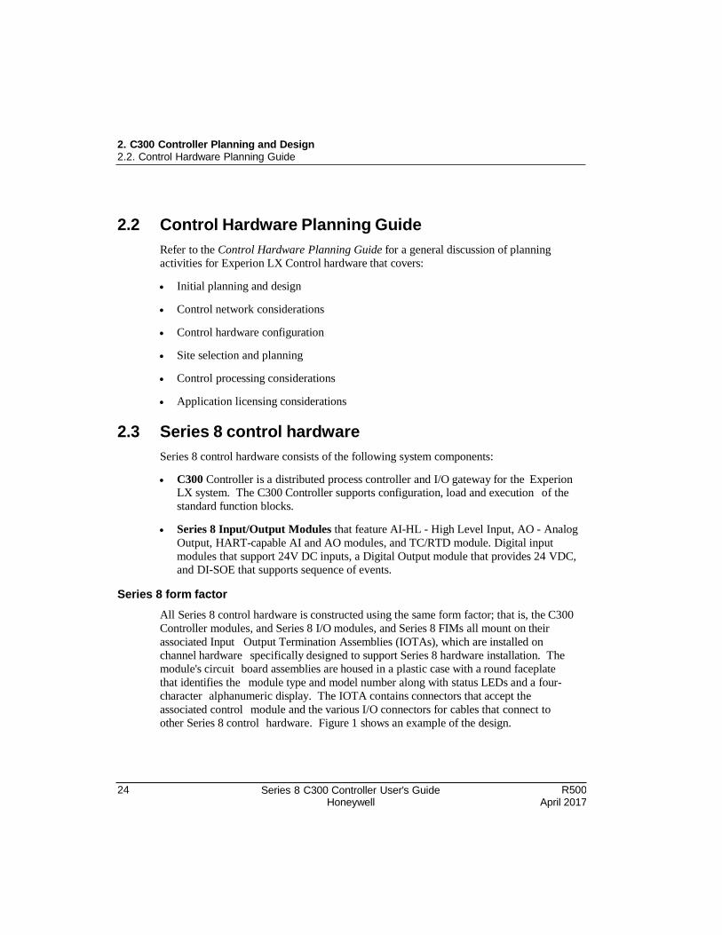
Series 8 form factor
All Series 8 control hardware is constructed using the same form factor; that is, the C300
Controller modules, and Series 8 I/O modules, and Series 8 FIMs all mount on their
associated Input Output Termination Assemblies (IOTAs), which are installed on
channel hardware specifically designed to support Series 8 hardware installation. The
module's circuit board assemblies are housed in a plastic case with a round faceplate
that identifies the module type and model number along with status LEDs and a four-
character alphanumeric display. The IOTA contains connectors that accept the
associated control module and the various I/O connectors for cables that connect to
other Series 8 control hardware. Figure 1 shows an example of the design.
R500 April 2017
Series 8 C300 Controller User's Guide Honeywell
25
2. C300 Controller Planning and Design 2.4. C300 Controller
Figure 1 Series 8 form factor example
26 Series 8 C300 Controller User's Guide Honeywell
R500 April 2017
2. C300 Controller Planning and Design 2.4. C300 Controller
2.4 C300 Controller
The C300 Controller is constructed using the Series C form factor that employs an Input
Output Termination Assembly (IOTA) and an electronics module which mounts and
connects to the IOTA.
The C300 Controller supports configuration, load and execution of the standard function
blocks. Note that there are a few exceptions defined below.
Exceptions
The following function blocks are not supported by the C300 Controller:
CAB related function blocks other than the Custom Data Block (CDB).
C300 Controller redundancy
The C300 Controller may operate in both non-redundant and redundant configurations.
Redundant operation requires a second identical controller and connecting cables, which
is the typical configuration. The switchover time from the active primary controller to
the backup controller of a redundant pair is less than 500 milliseconds.
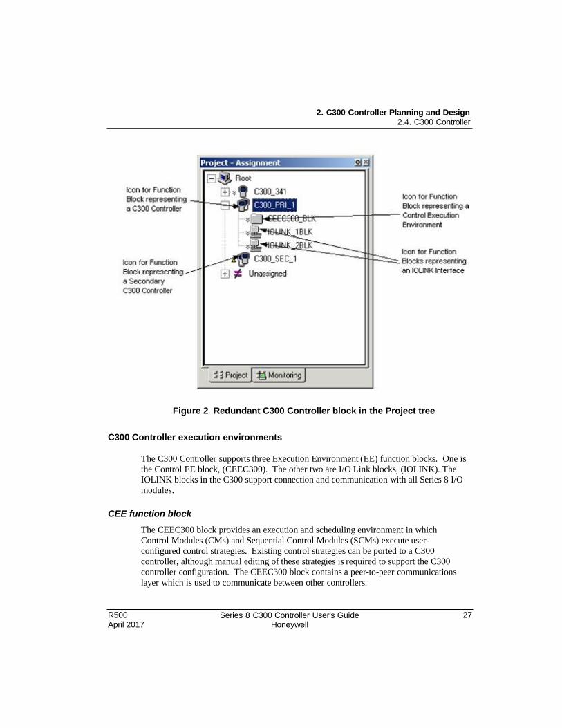
C300 Controller block
When a C300 Controller block is added to the Project tree in Control Builder, a graphic
representation of a controller module and its resident function blocks appears as shown in
Figure 2. The function blocks that are contained in the controller support multiple
execution environments. A Control Execution Environment block (CEEC300) and two
IOLINK blocks are contained in the controller and appear under the controller. When the
controller block is configured as redundant, the secondary controller block is added in the
Project tree.
REFERENCE - INTERNAL
For more details about Series 8 I/O, refer to the Series 8 I/O User’s Guide. For more details about FIM modules, refer to the Series 8 Fieldbus Interface Module User's Guide.
R500 April 2017
Series 8 C300 Controller User's Guide Honeywell
27
2. C300 Controller Planning and Design 2.4. C300 Controller
Figure 2 Redundant C300 Controller block in the Project tree
C300 Controller execution environments
The C300 Controller supports three Execution Environment (EE) function blocks. One is
the Control EE block, (CEEC300). The other two are I/O Link blocks, (IOLINK). The
IOLINK blocks in the C300 support connection and communication with all Series 8 I/O
modules.
CEE function block
The CEEC300 block provides an execution and scheduling environment in which
Control Modules (CMs) and Sequential Control Modules (SCMs) execute user-
configured control strategies. Existing control strategies can be ported to a C300
controller, although manual editing of these strategies is required to support the C300
controller configuration. The CEEC300 block contains a peer-to-peer communications
layer which is used to communicate between other controllers.
28 Series 8 C300 Controller User's Guide Honeywell
R500 April 2017
2. C300 Controller Planning and Design 2.5. Identify C300 Controller components
IOLink function blocks
Two IOLINK function blocks, which represent the 2 physical IO links on the C300
Controller IOTA, provide the user-configured I/O Link interface to support
communications with Series 8 I/O modules. Each IOLINK is configured to support
Series 8 I/O modules or 'No Link' if no I/O control is required. Each IOLINK supports
redundant and non-redundant communications.
I/O modules supported by the C300 Controller
The C300 Controller supports Series 8 I/O modules. Series 8 I/O modules are connected
to the C300 by a pair of I/O Link Interfaces. Two IO Link interfaces, which are
redundant, provide connection between the C300 controller and associated I/O modules.
Each IO links can be configured to support Series 8 I/O modules.
Refer to the Series 8 I/O User’s Guide for listings of the supported I/O modules.
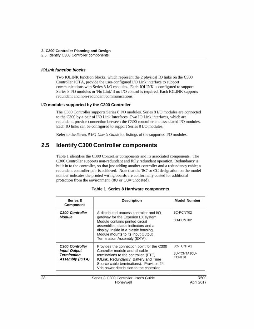
2.5 Identify C300 Controller components
Table 1 identifies the C300 Controller components and its associated components. The
C300 Controller supports non-redundant and fully redundant operation. Redundancy is
built in to the controller, so that just adding another controller and a redundancy cable; a
redundant controller pair is achieved. Note that the '8C' or CC designation on the model
number indicates the printed wiring boards are conformally coated for additional
protection from the environment, (8U or CU= uncoated).
Table 1 Series 8 Hardware components
Series 8 Component
Description Model Number
C300 Controller Module
A distributed process controller and I/O
gateway for the Experion LX system. Module contains printed circuit assemblies, status indicators and a display, inside in a plastic housing. Module mounts to its Input Output Termination Assembly (IOTA).
8C-PCNT02
8U-PCNT02
C300 Controller Input Output Termination Assembly (IOTA)
Provides the connection point for the C300 Controller module and all cable terminations to the controller, (FTE, IOLink, Redundancy, Battery and Time Source cable terminations). Provides 24 Vdc power distribution to the controller
8C-TCNTA1
8U-TCNTA1CU- TCNT01
R500 April 2017
Series 8 C300 Controller User's Guide Honeywell
29
2. C300 Controller Planning and Design 2.6. Control network considerations
Series 8 Component
Description Model Number
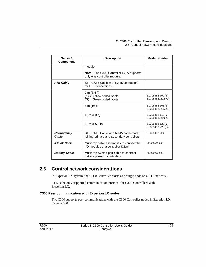
module.
Note: The C300 Controller IOTA supports
only one controller module.
FTE Cable STP CAT5 Cable with RJ 45 connectors for FTE connections.
2 m (6.5 ft) (Y) = Yellow coded boots (G) = Green coded boots
51305482-102 (Y) 513054820202 (G)
5 m (16 ft) 51305482-105 (Y) 513054820205 (G)
10 m (33 ft) 51305482-110 (Y) 513054820210 (G)
20 m (65.5 ft) 51305482-120 (Y) 51305482-220 (G)
Redundancy Cable
STP CAT5 Cable with RJ 45 connectors joining primary and secondary controllers.
51305482-xxx
IOLink Cable Multidrop cable assemblies to connect the I/O modules of a controller IOLink.
xxxxxxxx-xxx
Battery Cable Multidrop twisted pair cable to connect battery power to controllers.
xxxxxxxx-xxx
2.6 Control network considerations
In Experion LX system, the C300 Controller exists as a single node on a FTE network.
FTE is the only supported communication protocol for C300 Controllers with
Experion LX.
C300 Peer communication with Experion LX nodes
The C300 supports peer communications with the C300 Controller nodes in Experion LX Release 500.

R500 April 2017
Series 8 C300 Controller User's Guide Honeywell
31
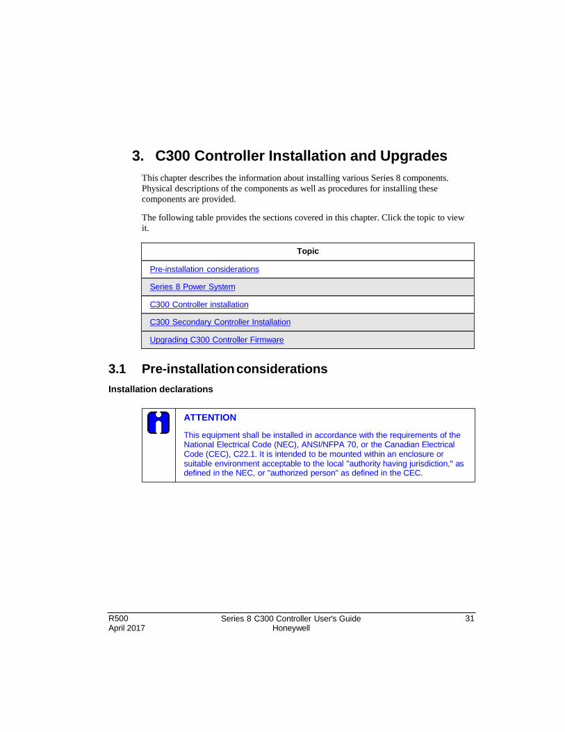
3. C300 Controller Installation and Upgrades
This chapter describes the information about installing various Series 8 components.
Physical descriptions of the components as well as procedures for installing these
components are provided.
The following table provides the sections covered in this chapter. Click the topic to view it.
Topic
Pre-installation considerations
Series 8 Power System
C300 Controller installation
C300 Secondary Controller Installation
Upgrading C300 Controller Firmware
3.1 Pre-installation considerations
Installation declarations
ATTENTION
This equipment shall be installed in accordance with the requirements of the National Electrical Code (NEC), ANSI/NFPA 70, or the Canadian Electrical Code (CEC), C22.1. It is intended to be mounted within an enclosure or suitable environment acceptable to the local "authority having jurisdiction," as defined in the NEC, or "authorized person" as defined in the CEC.
32 Series 8 C300 Controller User's Guide Honeywell
R500 April 2017
3. C300 Controller Installation and Upgrades 3.2. C300 Controller installation
Series 8 control hardware installation requirements
Refer to Planning Your Series 8 Control System section in the Control Hardware Planning Guide for details.
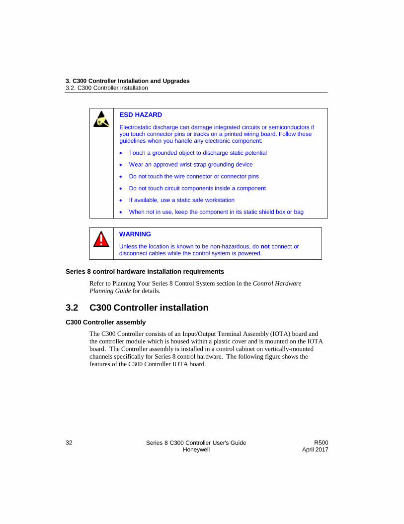
3.2 C300 Controller installation
C300 Controller assembly
The C300 Controller consists of an Input/Output Terminal Assembly (IOTA) board and
the controller module which is housed within a plastic cover and is mounted on the IOTA
board. The Controller assembly is installed in a control cabinet on vertically-mounted
channels specifically for Series 8 control hardware. The following figure shows the
features of the C300 Controller IOTA board.
WARNING
Unless the location is known to be non-hazardous, do not connect or disconnect cables while the control system is powered.
ESD HAZARD
Electrostatic discharge can damage integrated circuits or semiconductors if you touch connector pins or tracks on a printed wiring board. Follow these guidelines when you handle any electronic component:
Touch a grounded object to discharge static potential
Wear an approved wrist-strap grounding device
Do not touch the wire connector or connector pins
Do not touch circuit components inside a component
If available, use a static safe workstation
When not in use, keep the component in its static shield box or bag

R500 April 2017
Series 8 C300 Controller User's Guide Honeywell
31
3. C300 Controller Installation and Upgrades 3.2. C300 Controller installation

3. C300 Controller Installation and Upgrades 3.2. C300 Controller installation
R500 April 2017
Series 8 C300 Controller User's Guide Honeywell
33
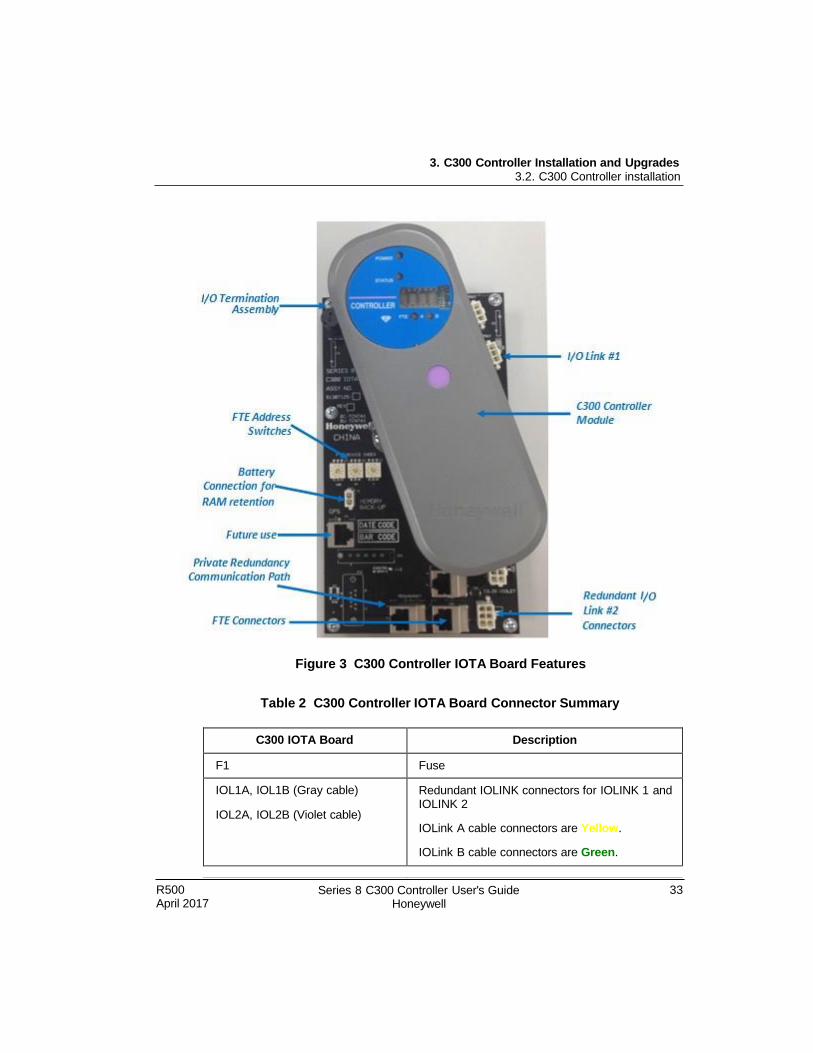
Figure 3 C300 Controller IOTA Board Features
Table 2 C300 Controller IOTA Board Connector Summary
C300 IOTA Board Description
F1 Fuse
IOL1A, IOL1B (Gray cable)
IOL2A, IOL2B (Violet cable)
Redundant IOLINK connectors for IOLINK 1 and IOLINK 2
IOLink A cable connectors are Yellow.
IOLink B cable connectors are Green.
3. C300 Controller Installation and Upgrades 3.2. C300 Controller installation
34 Series 8 C300 Controller User's Guide Honeywell
R500 April 2017
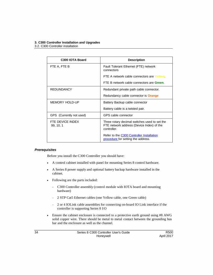
C300 IOTA Board Description
FTE A, FTE B Fault Tolerant Ethernet (FTE) network connectors
FTE A network cable connectors are Yellow.
FTE B network cable connectors are Green.
REDUNDANCY Redundant private path cable connector.
Redundancy cable connector is Orange
MEMORY HOLD-UP Battery Backup cable connector
Battery cable is a twisted pair.
GPS (Currently not used) GPS cable connector
FTE DEVICE INDEX
99, 10, 1
Three rotary decimal switches used to set the FTE network address (Device Index) of the controller.
Refer to the C300 Controller Installation procedure for setting the address.
Prerequisites
Before you install the C300 Controller you should have:
A control cabinet installed with panel for mounting Series 8 control hardware.
A Series 8 power supply and optional battery backup hardware installed in the cabinet.
Following are the parts included:
C300 Controller assembly (control module with IOTA board and mounting
hardware)
2 STP Cat5 Ethernet cables (one Yellow cable, one Green cable)
2 or 4 IOLink cable assemblies for connecting on-board IO Link interface if the controller is supporting Series 8 I/O
Ensure the cabinet enclosure is connected to a protective earth ground using #8 AWG solid copper wire. There should be metal to metal contact between the grounding bus
bar and the enclosure as well as the channel.
3. C300 Controller Installation and Upgrades 3.2. C300 Controller installation
R500 April 2017
Series 8 C300 Controller User's Guide Honeywell
35
Considerations
When installing a redundant controller pair consisting of a primary and a partner
secondary controller:
The secondary controller should be installed in the same cabinet as the primary controller.
The secondary controller may be installed on a separate channel from the primary controller.
To install a C300 Controller, perform the following steps.
Step Action
1 Refer to appropriate site location drawings for the specified controller installation location, controller Device Index (FTE address) and wiring diagrams.
2 Identify the mounting location on channel and align mounting holes in IOTA with screw hole locations on the channel.
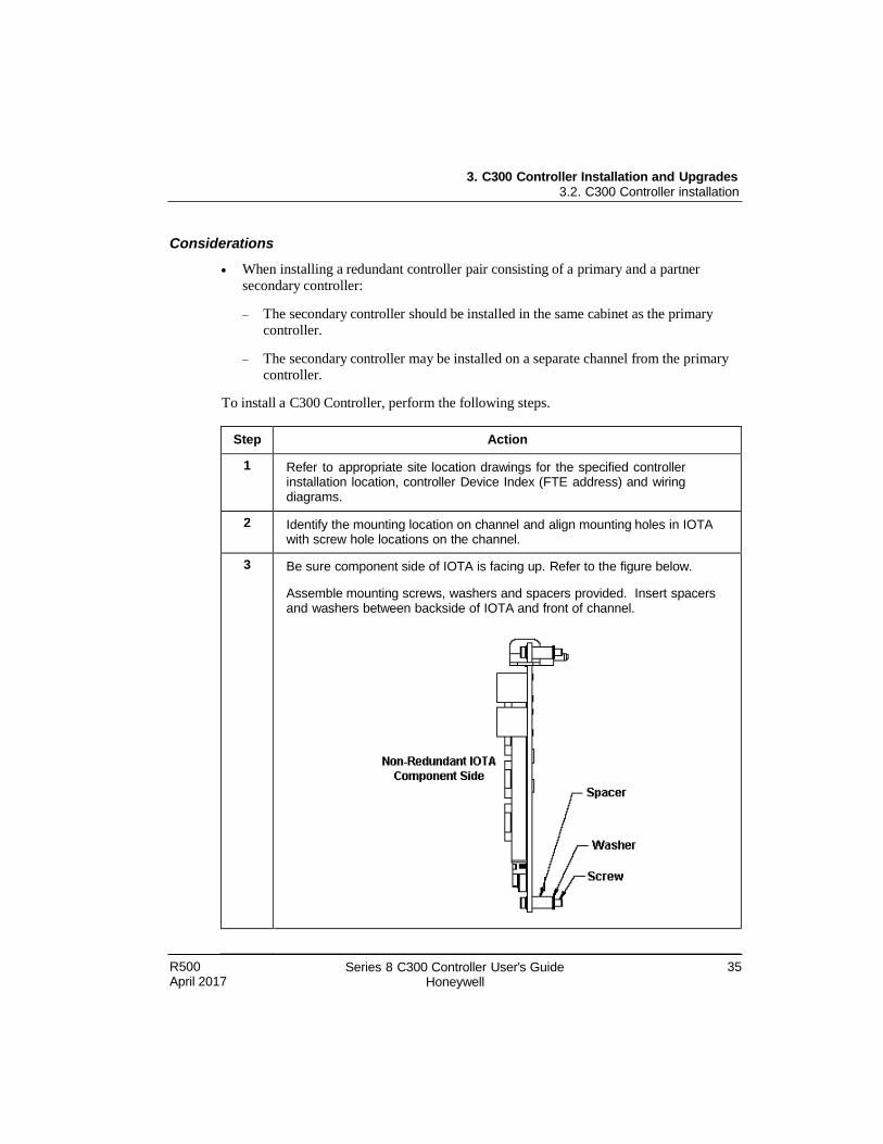
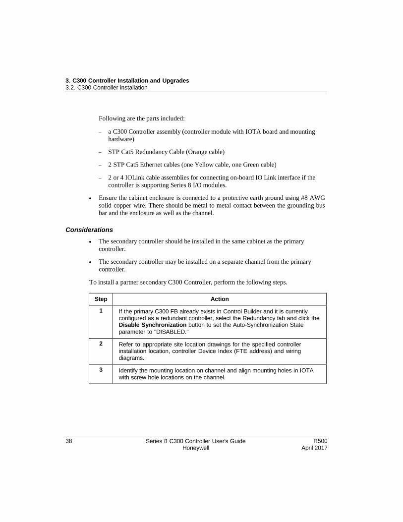
3 Be sure component side of IOTA is facing up. Refer to the figure below.
Assemble mounting screws, washers and spacers provided. Insert spacers and washers between backside of IOTA and front of channel.
3. C300 Controller Installation and Upgrades 3.2. C300 Controller installation
36 Series 8 C300 Controller User's Guide Honeywell
R500 April 2017
Step Action
4 Position the assembled IOTA board at the proper mounting location.
5 Thread the four mounting screws only half-way to attach the IOTA board to the channel. Do not tighten.
6 Tighten the mounting screws securing the IOTA board to the panel.
7 Connect FTE-A and FTE-B Ethernet link cables to the RJ-45 connectors on C300 IOTA board.
The Yellow Cat5 cable connects to the "FTEA" connector on the IOTA.
The Green Cat5 cable connects to the "FTEB" connector on the IOTA.
8 If using the IOLINK interface in the controller, connect IOLink cable pairs to IOTA board.
Four connectors on the IOTA provide redundant support for two IOLink interfaces IOLINK 1 (Gray) and IOLINK 2 (Violet). IOLink cable pairs include multidrop connectors to connect other I/O components to the IOLink.
Connect IOLINK cable pair to IOL1A and IOL1B for IOLINK 1 interface
of the controller.
Connect a second IOLINK cable pair to IOL2A and IOL2B for IOLINK 2 interface of the controller.
Note that when connecting Redundant C300 Controller pairs; connect the primary controller IOLINK and the redundant partner IOLINK to the same IOLink cable pair.
9 Install the two-wire twisted pair Battery cable onto the MEMORY HOLD-UP connector on the left side of the IOTA board.
10 Set the Device Index (FTE DEVICE INDEX) of the controller according to the site documentation by turning the three rotary decimal switches located on the IOTA board. Set the switches to the three digit address ranging from 001 to 509. The leftmost switch (100) is used to set the hundreds digit. The middle switch (10) is used to set the tens digit and the rightmost switch (1) sets the ones digit.
3. C300 Controller Installation and Upgrades 3.2. C300 Controller installation
R500 April 2017
Series 8 C300 Controller User's Guide Honeywell
37
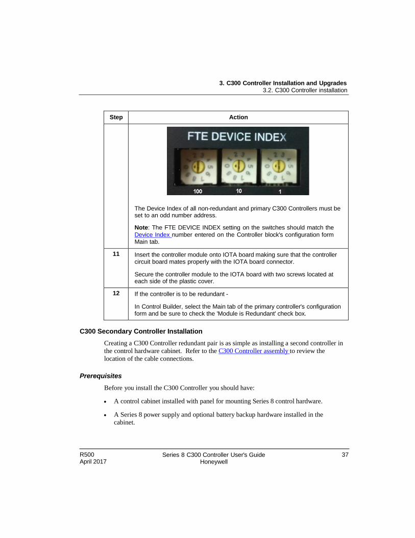
Step Action
The Device Index of all non-redundant and primary C300 Controllers must be set to an odd number address.
Note: The FTE DEVICE INDEX setting on the switches should match the
Device Index number entered on the Controller block's configuration form Main tab.
11 Insert the controller module onto IOTA board making sure that the controller circuit board mates properly with the IOTA board connector.
Secure the controller module to the IOTA board with two screws located at each side of the plastic cover.
12 If the controller is to be redundant -
In Control Builder, select the Main tab of the primary controller's configuration form and be sure to check the 'Module is Redundant' check box.
C300 Secondary Controller Installation
Creating a C300 Controller redundant pair is as simple as installing a second controller in
the control hardware cabinet. Refer to the C300 Controller assembly to review the
location of the cable connections.
Prerequisites
Before you install the C300 Controller you should have:
A control cabinet installed with panel for mounting Series 8 control hardware.
A Series 8 power supply and optional battery backup hardware installed in the
cabinet.
3. C300 Controller Installation and Upgrades 3.2. C300 Controller installation
38 Series 8 C300 Controller User's Guide Honeywell
R500 April 2017
Following are the parts included:
a C300 Controller assembly (controller module with IOTA board and mounting hardware)
STP Cat5 Redundancy Cable (Orange cable)
2 STP Cat5 Ethernet cables (one Yellow cable, one Green cable)
2 or 4 IOLink cable assemblies for connecting on-board IO Link interface if the
controller is supporting Series 8 I/O modules.
Ensure the cabinet enclosure is connected to a protective earth ground using #8 AWG
solid copper wire. There should be metal to metal contact between the grounding bus
bar and the enclosure as well as the channel.
Considerations
The secondary controller should be installed in the same cabinet as the primary
controller.
The secondary controller may be installed on a separate channel from the primary
controller.
To install a partner secondary C300 Controller, perform the following steps.
Step Action
1 If the primary C300 FB already exists in Control Builder and it is currently configured as a redundant controller, select the Redundancy tab and click the Disable Synchronization button to set the Auto-Synchronization State
parameter to "DISABLED."
2 Refer to appropriate site location drawings for the specified controller installation location, controller Device Index (FTE address) and wiring diagrams.
3 Identify the mounting location on channel and align mounting holes in IOTA with screw hole locations on the channel.
3. C300 Controller Installation and Upgrades 3.2. C300 Controller installation
R500 April 2017
Series 8 C300 Controller User's Guide Honeywell
39
Step Action
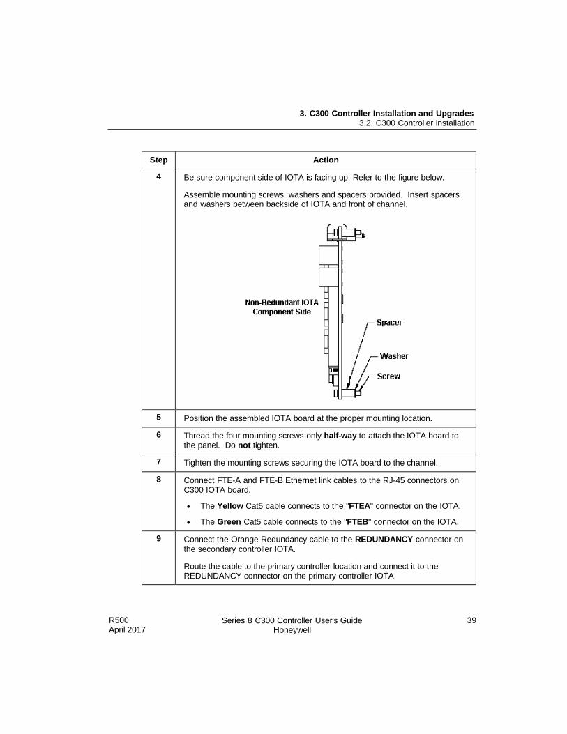
4 Be sure component side of IOTA is facing up. Refer to the figure below.
Assemble mounting screws, washers and spacers provided. Insert spacers and washers between backside of IOTA and front of channel.
5 Position the assembled IOTA board at the proper mounting location.
6 Thread the four mounting screws only half-way to attach the IOTA board to the panel. Do not tighten.
7 Tighten the mounting screws securing the IOTA board to the channel.
8 Connect FTE-A and FTE-B Ethernet link cables to the RJ-45 connectors on C300 IOTA board.
The Yellow Cat5 cable connects to the "FTEA" connector on the IOTA.
The Green Cat5 cable connects to the "FTEB" connector on the IOTA.
9 Connect the Orange Redundancy cable to the REDUNDANCY connector on
the secondary controller IOTA.
Route the cable to the primary controller location and connect it to the REDUNDANCY connector on the primary controller IOTA.
3. C300 Controller Installation and Upgrades 3.2. C300 Controller installation
40 Series 8 C300 Controller User's Guide Honeywell
R500 April 2017
Step Action
10 If using the IOLINK interface in the controller, connect IOLink cable pairs to IOTA board.
Four connectors on the IOTA provide redundant support for two IOLink interfaces IOLINK 1 (Gray) and IOLINK 2 (Violet). IOLink cable pairs include multidrop connectors to connect other I/O components to the IOLink.
Connect IOLINK cable pair to IOL1A and IOL1B for IOLINK 1 interface
of the controller.
Connect a second IOLINK cable pair to IOL2A and IOL2B for IOLINK 2 interface of the controller.
Note that when connecting Redundant C300 Controller pairs, connect the primary controller IOLINK and the redundant partner IOLINK to the same IOLink cable pair.
11 Install the two-wire twisted pair Battery cable onto the MEMORY HOLD-UP connector on the left side of the IOTA board.
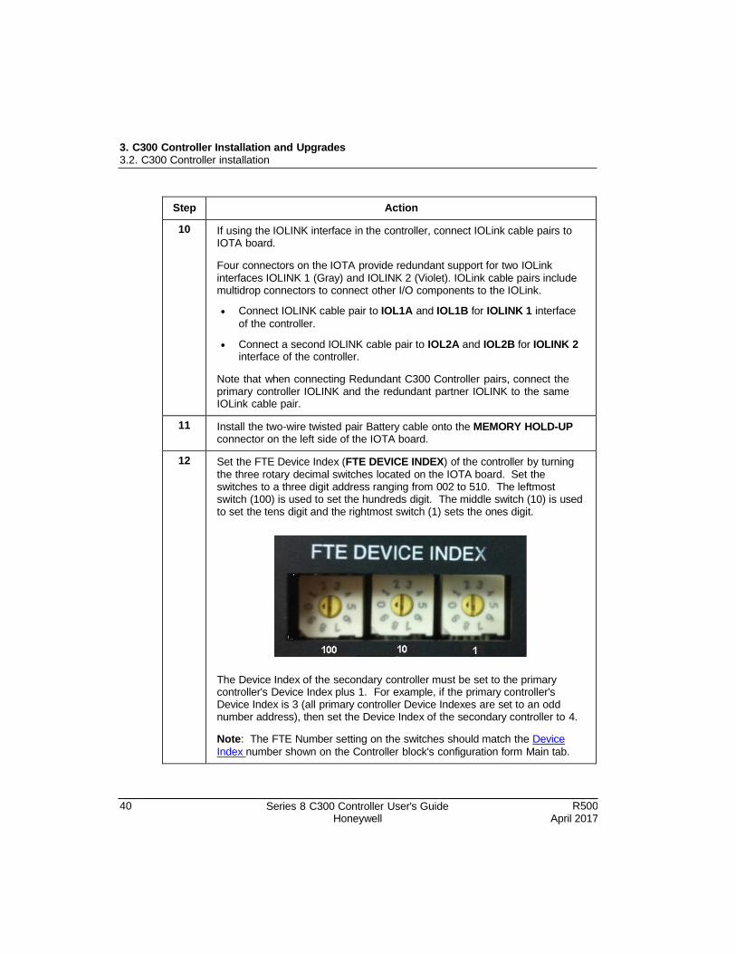
12 Set the FTE Device Index (FTE DEVICE INDEX) of the controller by turning the three rotary decimal switches located on the IOTA board. Set the switches to a three digit address ranging from 002 to 510. The leftmost switch (100) is used to set the hundreds digit. The middle switch (10) is used to set the tens digit and the rightmost switch (1) sets the ones digit.
The Device Index of the secondary controller must be set to the primary controller's Device Index plus 1. For example, if the primary controller's Device Index is 3 (all primary controller Device Indexes are set to an odd number address), then set the Device Index of the secondary controller to 4.
Note: The FTE Number setting on the switches should match the Device
Index number shown on the Controller block's configuration form Main tab.
R500 April 2017
Series 8 C300 Controller User's Guide Honeywell
41
3. C300 Controller Installation and Upgrades 3.4. Series 8 I/O modules installation
Step Action
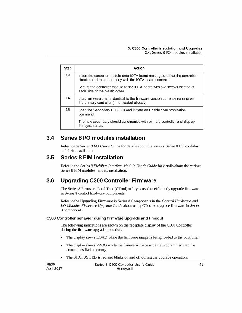
13 Insert the controller module onto IOTA board making sure that the controller circuit board mates properly with the IOTA board connector.
Secure the controller module to the IOTA board with two screws located at each side of the plastic cover.
14 Load firmware that is identical to the firmware version currently running on the primary controller (if not loaded already).
15 Load the Secondary C300 FB and initiate an Enable Synchronization command.
The new secondary should synchronize with primary controller and display the sync status.
3.4 Series 8 I/O modules installation
Refer to the Series 8 I/O User's Guide for details about the various Series 8 I/O modules
and their installation.
3.5 Series 8 FIM installation
Refer to the Series 8 Fieldbus Interface Module User's Guide for details about the various
Series 8 FIM modules and its installation.
3.6 Upgrading C300 Controller Firmware
The Series 8 Firmware Load Tool (CTool) utility is used to efficiently upgrade firmware
in Series 8 control hardware components.
Refer to the Upgrading Firmware in Series 8 Components in the Control Hardware and
I/O Modules Firmware Upgrade Guide about using CTool to upgrade firmware in Series
8 components
C300 Controller behavior during firmware upgrade and timeout
The following indications are shown on the faceplate display of the C300 Controller
during the firmware upgrade operation.
The display shows LOAD while the firmware image is being loaded to the controller.
The display shows PROG while the firmware image is being programmed into the
controller's flash memory.
The STATUS LED is red and blinks on and off during the upgrade operation.

40 Series 8 C300 Controller User's Guide Honeywell
R500 April 2017
3. C300 Controller Installation and Upgrades 3.5. Upgrading C300 Controller Firmware
The controller is set to timeout in 4.5 minutes if the firmware upgrade operation is not completed. When the timeout occurs, the controller aborts the upgrade operation and
returns to the operating state (ALIV or RDY) prior to the start of the firmware upgrade.


3. C300 Controller Installation and Upgrades 3.5. Upgrading C300 Controller Firmware
42 Series 8 C300 Controller User's Guide Honeywell
R500 April 2017
R500 April 2017
Series 8 C300 Controller User's Guide Honeywell
43
4. C300 Controller Configuration
This chapter describes the information about creating and configuring the various
function blocks using Control Builder. Also included are procedures to create Control
Modules in which control strategies are built. The control modules then can be assigned
to a CEE block.
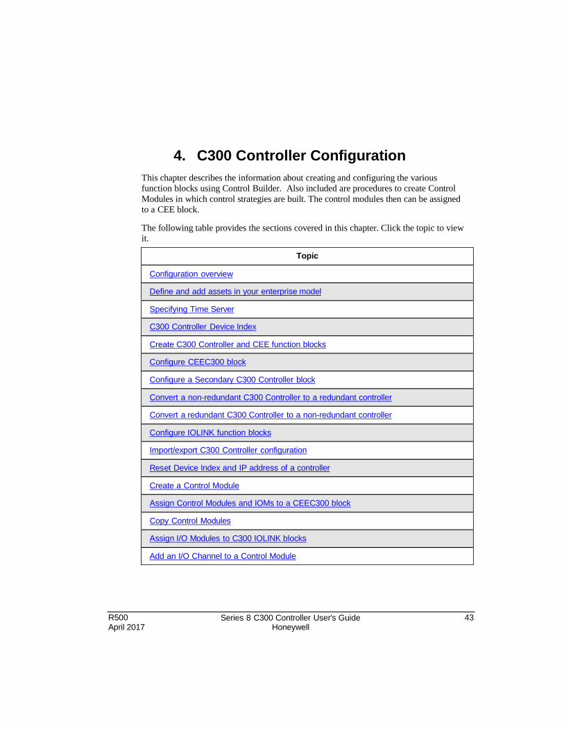
The following table provides the sections covered in this chapter. Click the topic to view it.
Topic
Configuration overview
Define and add assets in your enterprise model
Specifying Time Server
C300 Controller Device Index
Create C300 Controller and CEE function blocks
Configure CEEC300 block
Configure a Secondary C300 Controller block
Convert a non-redundant C300 Controller to a redundant controller
Convert a redundant C300 Controller to a non-redundant controller
Configure IOLINK function blocks
Import/export C300 Controller configuration
Res et Device Index and IP address of a controller
Create a Control Module
Assign Control Modules and IOMs to a CEEC300 block
Copy Control Modules
Assign I/O Modules to C300 IOLINK blocks
Add an I/O Channel to a Control Module
4. C300 Controller Configuration 4.1. Configuration overview
44 Series 8 C300 Controller User's Guide Honeywell
R500 April 2017
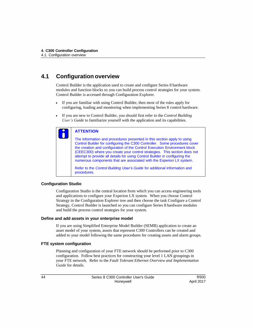
4.1 Configuration overview
Control Builder is the application used to create and configure Series 8 hardware
modules and function blocks so you can build process control strategies for your system.
Control Builder is accessed through Configuration Explorer.
If you are familiar with using Control Builder, then most of the rules apply for
configuring, loading and monitoring when implementing Series 8 control hardware.
If you are new to Control Builder, you should first refer to the Control Building
User’s Guide to familiarize yourself with the application and its capabilities.
Configuration Studio
Configuration Studio is the central location from which you can access engineering tools
and applications to configure your Experion LX system. When you choose Control
Strategy in the Configuration Explorer tree and then choose the task Configure a Control
Strategy, Control Builder is launched so you can configure Series 8 hardware modules
and build the process control strategies for your system.
Define and add assets in your enterprise model
If you are using Simplified Enterprise Model Builder (SEMB) application to create an
asset model of your system, assets that represent C300 Controllers can be created and
added to your model following the same procedures for creating assets and alarm groups.
FTE system configuration
Planning and configuration of your FTE network should be performed prior to C300
configuration. Follow best practices for constructing your level 1 LAN groupings in
your FTE network. Refer to the Fault Tolerant Ethernet Overview and Implementation
Guide for details.
ATTENTION
The information and procedures presented in this section apply to using Control Builder for configuring the C300 Controller. Some procedures cover the creation and configuration of the Control Execution Environment block (CEEC300) where you create your control strategies. This section does not attempt to provide all details for using Control Builder in configuring the numerous components that are associated with the Experion LX system.
Refer to the Control Building User’s Guide for additional information and procedures.
4. C300 Controller Configuration 4.2. Create C300 Controller and CEE function blocks
R500 April 2017
Series 8 C300 Controller User's Guide Honeywell
45
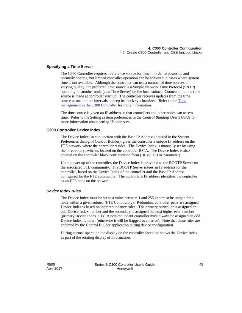
Specifying a Time Server
The C300 Controller requires a reference source for time in order to power up and
normally operate, but limited controller operation can be achieved in cases where system
time is not available. Although the controller can use a number of time sources of
varying quality, the preferred time source is a Simple Network Time Protocol (SNTP)
operating on another node (as a Time Server) on the local subnet. Connection to the time
source is made at controller start up. The controller receives updates from the time
source at one minute intervals to keep its clock synchronized. Refer to the Time
management in the C300 Controller for more information.
The time source is given an IP address so that controllers and other nodes can access
time. Refer to the Setting system preferences in the Control Building User's Guide for more information about setting IP addresses.
C300 Controller Device Index
The Device Index, in conjunction with the Base IP Address (entered in the System
Preferences dialog of Control Builder), gives the controller a unique IP address on the
FTE network where the controller resides. The Device Index is manually set by using
the three rotary switches located on the controller IOTA. The Device Index is also
entered on the controller block configuration form (DEVICEIDX parameter).
Upon power up of the controller, the Device Index is provided to the BOOTP Server on
the associated FTE community. The BOOTP Server issues an IP address for the
controller, based on the Device Index of the controller and the Base IP Address
configured for the FTE community. The controller's IP address identifies the controller
as an FTE node on the network.
Device Index rules
The Device Index must be set to a value between 1 and 255 and must be unique for a
node within a given subnet, (FTE Community). Redundant controller pairs are assigned
Device Indexes based on their redundancy roles. The primary controller is assigned an
odd Device Index number and the secondary is assigned the next higher even number
(primary Device Index + 1). A non-redundant controller must always be assigned an odd
Device Index number, (otherwise it will be flagged as an error). Note that these rules are
enforced by the Control Builder application during device configuration.
During normal operation the display on the controller faceplate shows the Device Index
as part of the rotating display of information.
46 Series 8 C300 Controller User's Guide Honeywell
R500 April 2017
4. C300 Controller Configuration 4.2. Create C300 Controller and CEE function blocks
4.2 Create C300 Controller and CEE function blocks
You can create function blocks that represent a C300 Controller and its associated
Control Execution Environment (CEE). Once created, the function blocks appear in the
Project tab view of Control Builder. The CEEC300 block supports execution of a set of
function blocks for solving control applications which run in the C300 as a software layer
built on top of the control software infrastructure.
Two additional EE blocks are also created when a C300 Controller block is created. These blocks, IOLINK1 and IOLINK 2, provide the controller interface for associated
Series 8 Module blocks.
Prerequisites
You have started Configuration Studio and launched the Control Builder application.
You have logged on with sufficient privileges to create control strategies using Control Builder.
You have configured the applicable IP addresses when you set up your FTE network.
You have configured applicable Base IP address and IP addresses for Network Time
Protocol (NTP) Servers through the System Preferences dialog in Control Builder.
Refer to the Setting system preferences in the Control Building User's Guide for more
information about setting IP addresses.
TIP
You can configure a C300 Controller block in the Control Builder Project tab without the controller hardware being installed.
R500 April 2017
Series 8 C300 Controller User's Guide Honeywell
47
4. C300 Controller Configuration 4.2. Create C300 Controller and CEE function blocks
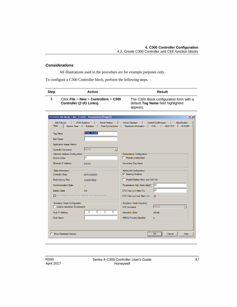
Considerations
All illustrations used in the procedure are for example purposes only.
To configure a C300 Controller block, perform the following steps.
Step Action Result
1 Click File > New > Controllers > C300 Controller (2 I/O Links).
The C300 Block configuration form with a default Tag Name field highlighted
appears.
48 Series 8 C300 Controller User's Guide Honeywell
R500 April 2017
4. C300 Controller Configuration 4.2. Create C300 Controller and CEE function blocks
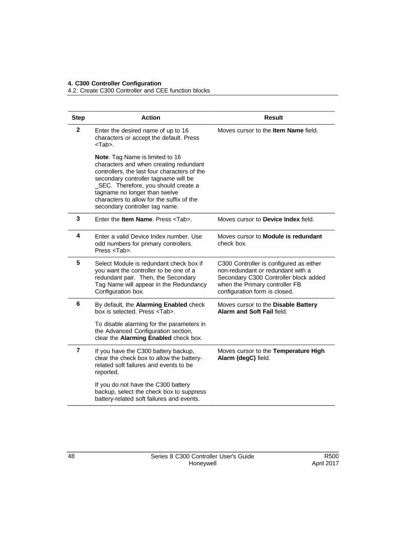
Step Action Result
2 Enter the desired name of up to 16
characters or accept the default. Press <Tab>.
Note: Tag Name is limited to 16
characters and when creating redundant controllers, the last four characters of the secondary controller tagname will be _SEC. Therefore, you should create a tagname no longer than twelve characters to allow for the suffix of the secondary controller tag name.
Moves cursor to the Item Name field.
3 Enter the Item Name. Press <Tab>. Moves cursor to Device Index field.
4 Enter a valid Device Index number. Use
odd numbers for primary controllers. Press <Tab>.
Moves cursor to Module is redundant check box.
5 Select Module is redundant check box if you want the controller to be one of a redundant pair. Then, the Secondary Tag Name will appear in the Redundancy Configuration box.
C300 Controller is configured as either non-redundant or redundant with a Secondary C300 Controller block added when the Primary controller FB configuration form is closed.
6 By default, the Alarming Enabled check box is selected. Press <Tab>.
To disable alarming for the parameters in the Advanced Configuration section, clear the Alarming Enabled check box.
Moves cursor to the Disable Battery Alarm and Soft Fail field.
7 If you have the C300 battery backup, clear the check box to allow the battery- related soft failures and events to be reported.
If you do not have the C300 battery backup, select the check box to suppress battery-related soft failures and events.
Moves cursor to the Temperature High Alarm (degC) field.
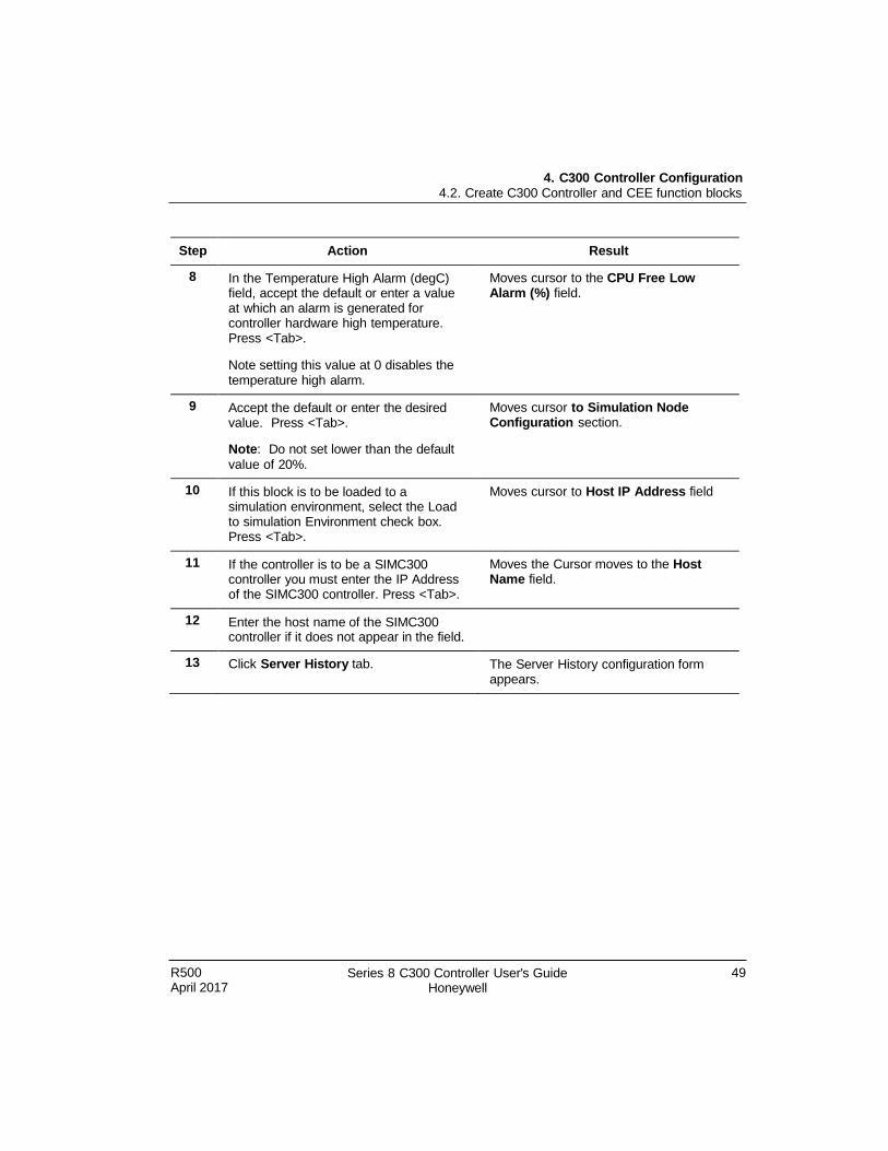
R500 April 2017
Series 8 C300 Controller User's Guide Honeywell
49
4. C300 Controller Configuration 4.2. Create C300 Controller and CEE function blocks
Step Action Result
8 In the Temperature High Alarm (degC) field, accept the default or enter a value at which an alarm is generated for controller hardware high temperature. Press <Tab>.
Note setting this value at 0 disables the temperature high alarm.
Moves cursor to the CPU Free Low Alarm (%) field.
9 Accept the default or enter the desired value. Press <Tab>.
Note: Do not set lower than the default
value of 20%.
Moves cursor to Simulation Node Configuration section.
10 If this block is to be loaded to a simulation environment, select the Load to simulation Environment check box. Press <Tab>.
Moves cursor to Host IP Address field
11 If the controller is to be a SIMC300 controller you must enter the IP Address of the SIMC300 controller. Press <Tab>.
Moves the Cursor moves to the Host Name field.
12 Enter the host name of the SIMC300 controller if it does not appear in the field.
13 Click Server History tab. The Server History configuration form appears.
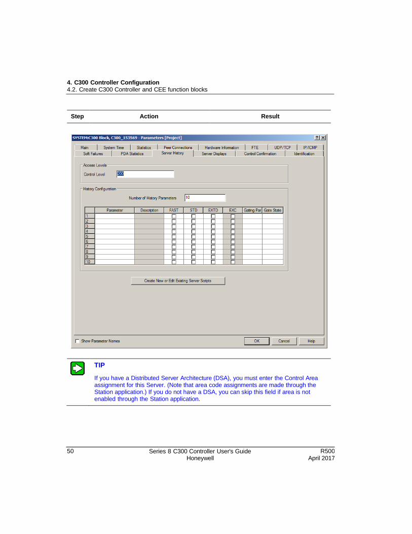
4. C300 Controller Configuration 4.2. Create C300 Controller and CEE function blocks
50 Series 8 C300 Controller User's Guide Honeywell
R500 April 2017
Step Action Result
TIP
If you have a Distributed Server Architecture (DSA), you must enter the Control Area assignment for this Server. (Note that area code assignments are made through the Station application.) If you do not have a DSA, you can skip this field if area is not enabled through the Station application.
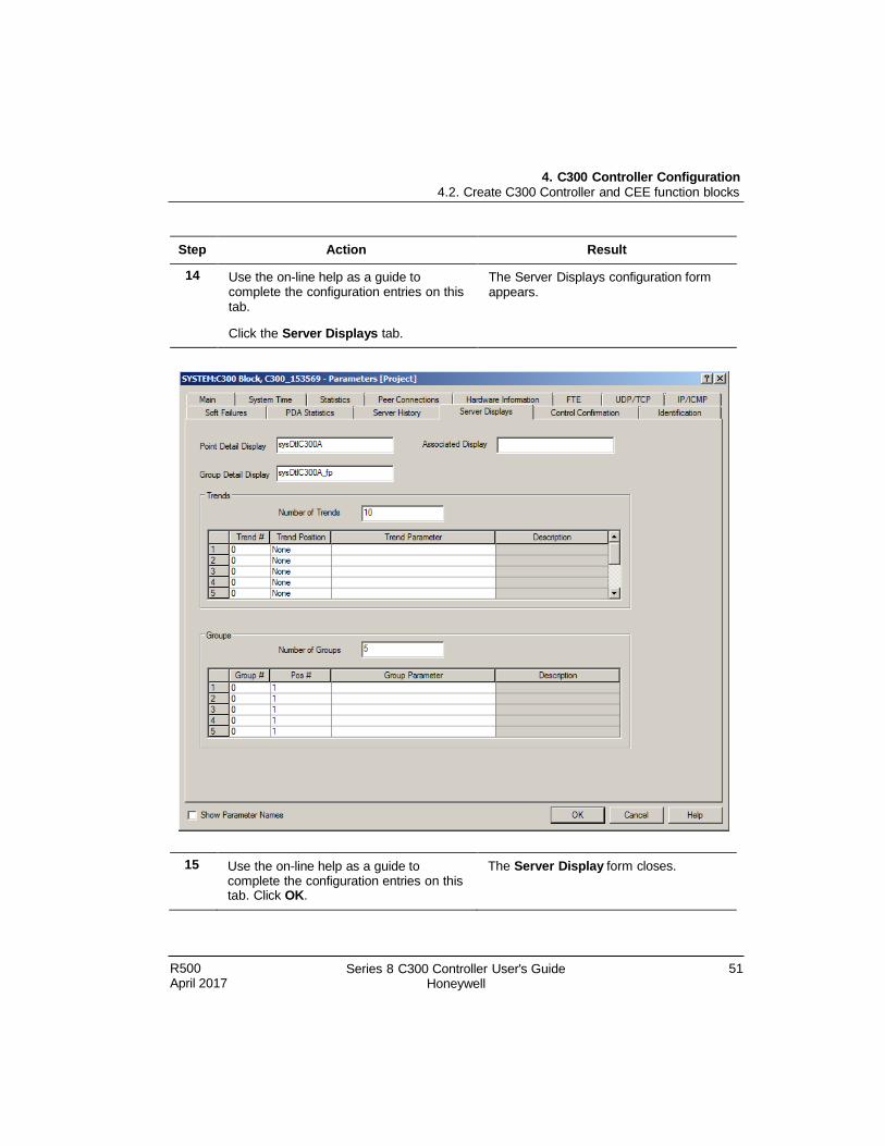
4. C300 Controller Configuration 4.2. Create C300 Controller and CEE function blocks
R500 April 2017
Series 8 C300 Controller User's Guide Honeywell
51
Step Action Result
14 Use the on-line help as a guide to complete the configuration entries on this tab.
Click the Server Displays tab.
The Server Displays configuration form appears.
15 Use the on-line help as a guide to complete the configuration entries on this tab. Click OK.
The Server Display form closes.
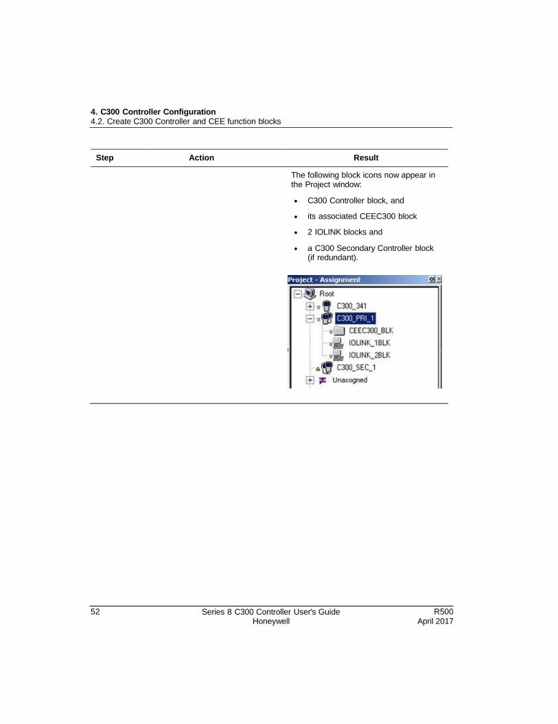
4. C300 Controller Configuration 4.2. Create C300 Controller and CEE function blocks
52 Series 8 C300 Controller User's Guide Honeywell
R500 April 2017
Step Action Result
The following block icons now appear in the Project window:
C300 Controller block, and
its associated CEEC300 block
2 IOLINK blocks and
a C300 Secondary Controller block (if redundant).
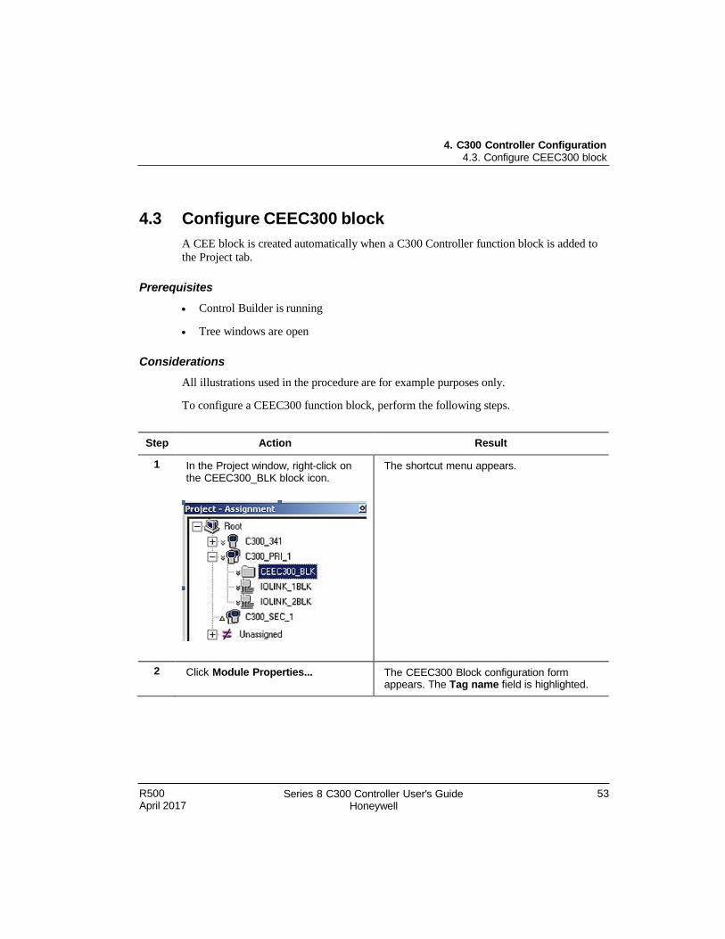
R500 April 2017
Series 8 C300 Controller User's Guide Honeywell
53
4. C300 Controller Configuration 4.3. Configure CEEC300 block
4.3 Configure CEEC300 block
A CEE block is created automatically when a C300 Controller function block is added to
the Project tab.
Prerequisites
Control Builder is running
Tree windows are open
Considerations
All illustrations used in the procedure are for example purposes only.
To configure a CEEC300 function block, perform the following steps.
Step Action Result
1 In the Project window, right-click on the CEEC300_BLK block icon.
The shortcut menu appears.
2 Click Module Properties... The CEEC300 Block configuration form appears. The Tag name field is highlighted.
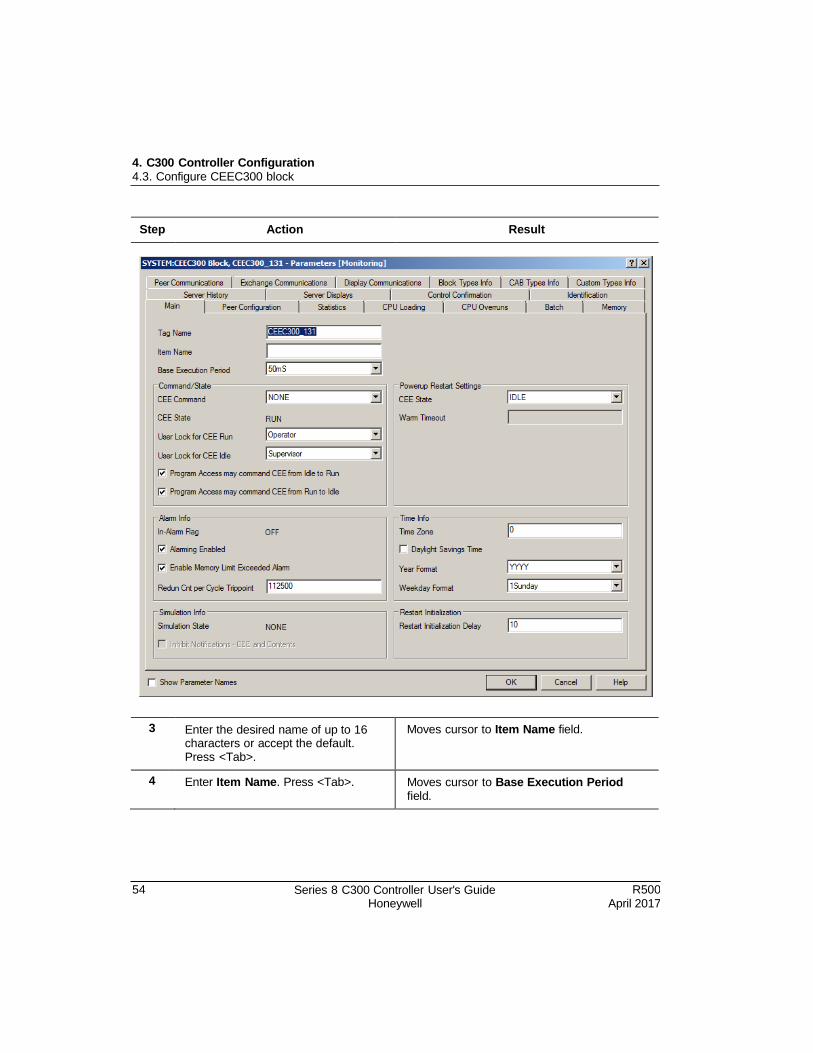
54 Series 8 C300 Controller User's Guide Honeywell
R500 April 2017
4. C300 Controller Configuration 4.3. Configure CEEC300 block
Step Action Result
3 Enter the desired name of up to 16 characters or accept the default. Press <Tab>.
Moves cursor to Item Name field.
4 Enter Item Name. Press <Tab>. Moves cursor to Base Execution Period field.

R500 April 2017
Series 8 C300 Controller User's Guide Honeywell
55
4. C300 Controller Configuration 4.3. Configure CEEC300 block
Step Action Result
5 Select the Base Execution Period from the drop-down list. Press <Tab>.
Note: Prior to selecting the IOLINK
configuration for the controller, the base execution period must be selected. Otherwise, an error message appears as follows: "CEE BASEPERIOD cannot be changed because IOLINK TYPE of at least one IOLINK of this C300 has been configured.”
Moves cursor to User Lock for CEE Run field.
Note that CEE Command field is available only in Monitor mode.
6 Accept the default or select desired
user from the drop-down list. Press <Tab>.
Moves cursor to User Lock for CEE Idle field.
7 Accept the default or select the desired user from the drop-down list. Press <Tab>.
Moves cursor to Program Access may command CEE from Idle to Run check box.
8 Select the check box to enable access. Press <Tab>.
Moves cursor to Program Access may command CEE from Run to Idle check box.
9 Select the check box to enable access. Press <Tab>.
Moves cursor to the Alarming Enabled check box.
10 Accept the default (Alarming Enabled), or clear the box to disable alarming function. Press <Tab>.
Moves cursor to the Enable Memory Limit Exceeded Alarm check box.
11 Accept the default (Memory Limit Exceeded Alarm enabled), or clear
the box to disable alarming function. Press <Tab>.
Moves cursor to the CEE State under the Powerup Restart Settings section.
12 Accept the default or select the desired state from the down-down list list.
Note that if you select LASTTIMEOUT state, then the Warm Timeout field is active.
13 If the Warm Timeout field is active, accept the default or enter the desired timeout value. Press <Tab>.
Moves cursor to the Time Zone field.
56 Series 8 C300 Controller User's Guide Honeywell
R500 April 2017
4. C300 Controller Configuration 4.3. Configure CEEC300 block
Step Action Result
14 Enter the appropriate value for the time zone of the controller location. Press <Tab>.
Moves cursor to the Daylight Savings Time check box.
15 Select the check box if the Daylight Savings Time is in effect for this location. Press <Tab>.
Moves cursor to the Year Format field.
16 Accept the default or select the desired format from the drop-down list. Press <Tab>.
Moves cursor to the Weekday Format field.
17 Accept the default or select the The Store Expiration Time Field is
desired format from the drop-down highlighted in the Peer Defaults section.
list.
Click the Peer Configuration tab.
18 Accept the default or enter the desired value. Press <Tab>.
Moves cursor to Subscription Period field.
19 Accept the default or select the desired period from the drop-down list. Press <Tab>.
Moves cursor to Number of Peer Environments field.
TIP The Number of Peer Environments and Peer Environment Table are interactive. The
value entered for the Number of Peer Environments determines how many rows appear in the Peer Environment Table.
20 Enter the number of peer
environments for this controller. Press <Tab>.
Or, skip this field, if no peer environments will be used. Click Server History tab and proceed to Step 25.
If peer environments will be used, cursor moves to the Peer Environment Name column in the Peer Environment Table section.
21 Enter the valid name for the existing peer environment.
Press <Tab>.
Moves cursor to Peer Subscription Period column.
R500 April 2017
Series 8 C300 Controller User's Guide Honeywell
57
4. C300 Controller Configuration 4.3. Configure CEEC300 block
REFERENCE - INTERNAL
Refer to the Experion LX Control Builder Components Reference, Component Categories and Types and the Experion LX Planning Guide.
Step Action Result
22 Accept default or select another value specific to the given environment from the drop-down list.
Press <Tab>.
Moves cursor to Peer Store Expiration Time column.
23 Accept the default or enter the desired value. Click Batch tab.
Moves cursor to Batch Events Memory field.
24 Accept the default or select the desired state from the drop-down list. Click Server History tab.
The Server History configuration form appears.
25 Use the on-line help as a guide to complete the configuration entries on this tab. Click the Server Displays
tab.
The Server Displays configuration form appears.
26 Use the on-line help as a guide to complete the configuration entries on this tab. Click OK.
The form is closed.
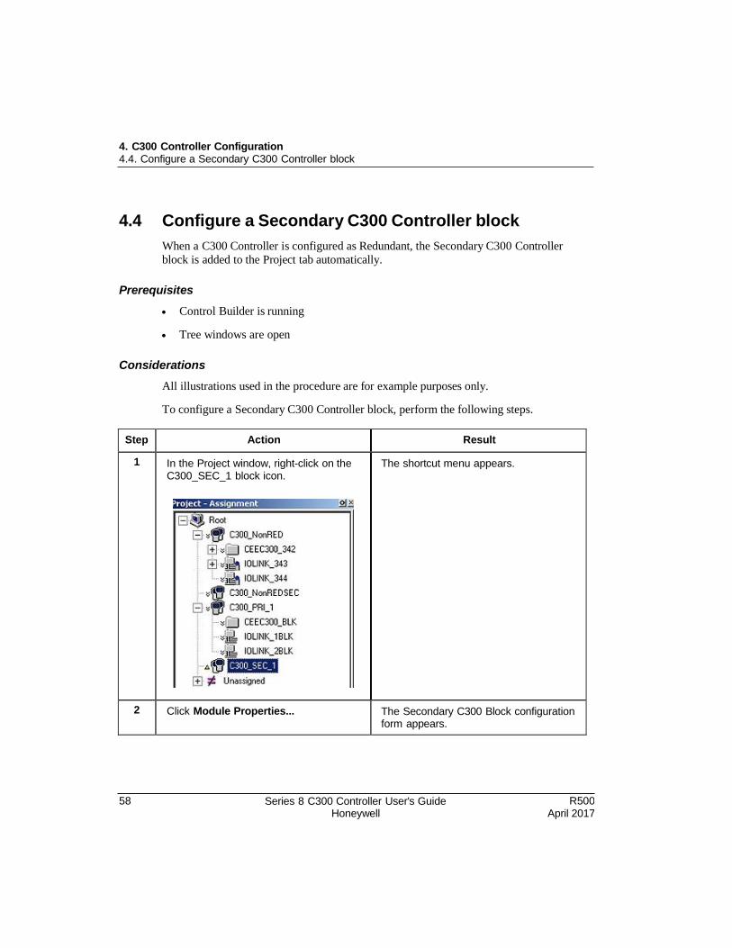
58 Series 8 C300 Controller User's Guide Honeywell
R500 April 2017
4. C300 Controller Configuration 4.4. Configure a Secondary C300 Controller block
4.4 Configure a Secondary C300 Controller block
When a C300 Controller is configured as Redundant, the Secondary C300 Controller
block is added to the Project tab automatically.
Prerequisites
Control Builder is running
Tree windows are open
Considerations
All illustrations used in the procedure are for example purposes only.
To configure a Secondary C300 Controller block, perform the following steps.
Step Action Result
1 In the Project window, right-click on the C300_SEC_1 block icon.
The shortcut menu appears.
2 Click Module Properties... The Secondary C300 Block configuration form appears.
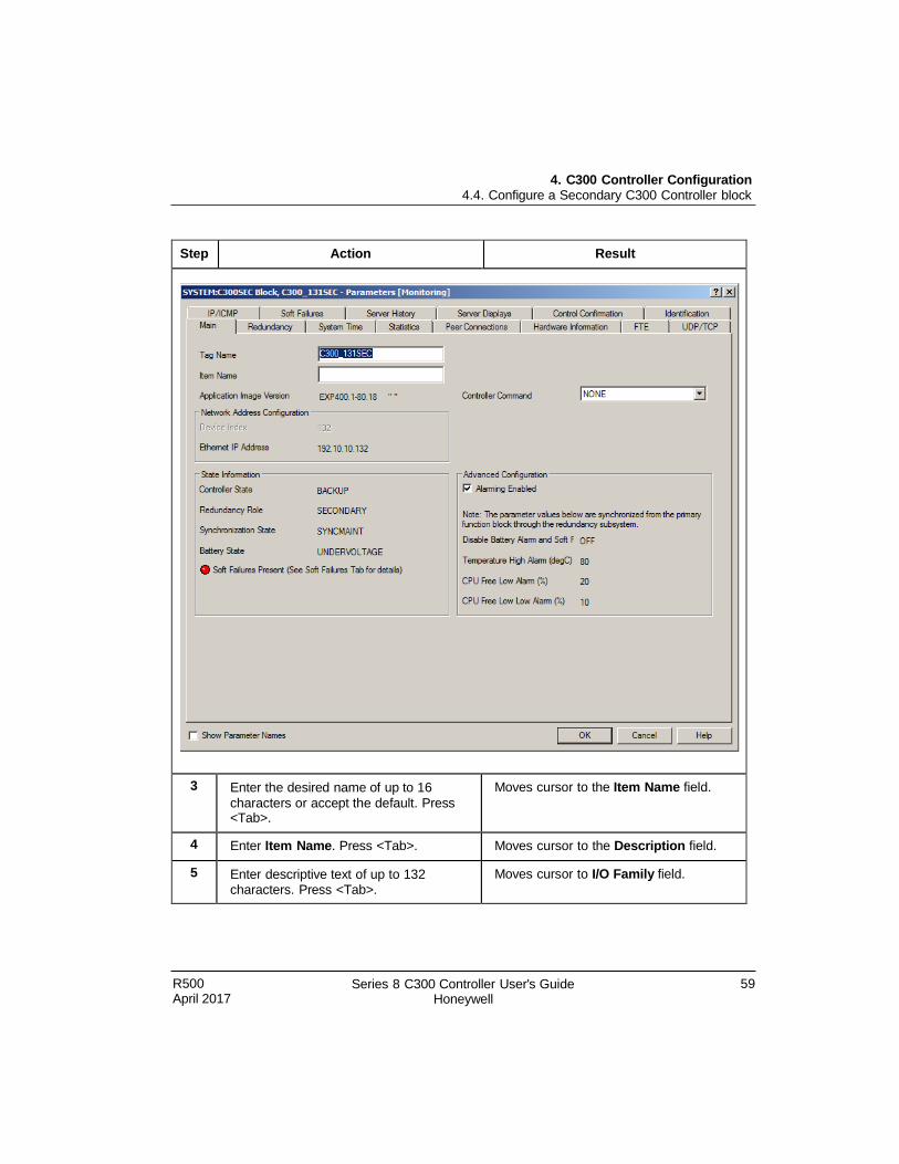
R500 April 2017
Series 8 C300 Controller User's Guide Honeywell
59
4. C300 Controller Configuration 4.4. Configure a Secondary C300 Controller block
Step Action Result
3 Enter the desired name of up to 16
characters or accept the default. Press <Tab>.
Moves cursor to the Item Name field.
4 Enter Item Name. Press <Tab>. Moves cursor to the Description field.
5 Enter descriptive text of up to 132 characters. Press <Tab>.
Moves cursor to I/O Family field.
4. C300 Controller Configuration 4.5. Convert a non-redundant C300 Controller to a redundant controller
60 Series 8 C300 Controller User's Guide Honeywell
R500 April 2017
Step Action Result
6 Accept the default or click down-down list and select I/O type.
Click OK.
The IOLINK block configuration form closes since no other data on this form is available in the Project view.
7 Repeat this procedure from step 1 to configure other IOLINK blocks.
4.5 Convert a non-redundant C300 Controller to a redundant controller
You can convert a single non-redundant C300 Controller to a redundant controller by configuring the controller as redundant. The controller icon which represents the
secondary controller is then added to the Project tab.
Prerequisites
Control Builder is running
Tree windows are open
Ensure that a C300 Controller is properly installed in the same control cabinet as the
C300 Controller designated to become the redundant partner.
The C300 Controller hardware and firmware must be identical for both controllers in
a redundant pair.
Considerations
Do not connect the Redundancy cable between the two controllers until instructed to
do so.
This procedure can be performed on-process.
All illustrations used in the procedure are for example purposes only.
To convert a non-redundant C300 Controller to a Redundant controller, perform the
following steps.
Step Action Result
1 In the Project window, right-click on the C300_NonRED Controller block
The shortcut menu appears.
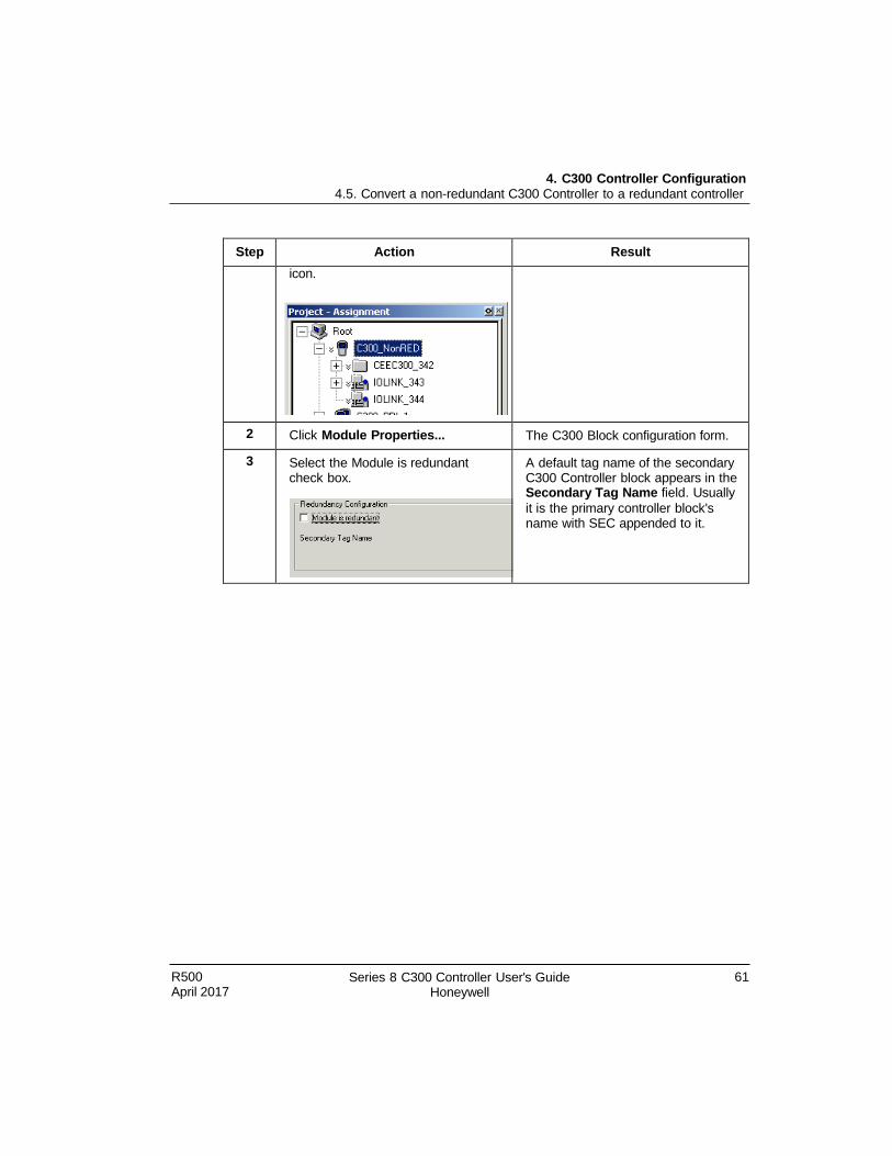
4. C300 Controller Configuration 4.5. Convert a non-redundant C300 Controller to a redundant controller
R500 April 2017
Series 8 C300 Controller User's Guide Honeywell
61
Step Action Result
icon.
2 Click Module Properties... The C300 Block configuration form.
3 Select the Module is redundant check box.
A default tag name of the secondary C300 Controller block appears in the Secondary Tag Name field. Usually
it is the primary controller block's name with SEC appended to it.
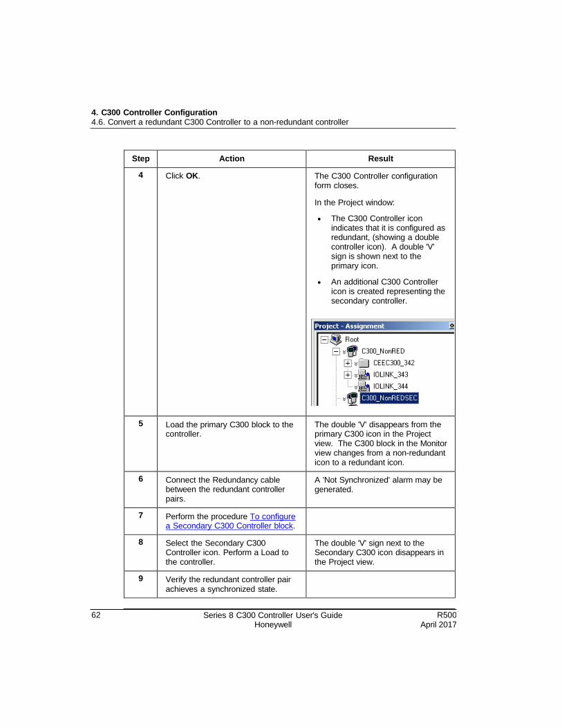
4. C300 Controller Configuration 4.6. Convert a redundant C300 Controller to a non-redundant controller
62 Series 8 C300 Controller User's Guide Honeywell
R500 April 2017
Step Action Result
4 Click OK. The C300 Controller configuration form closes.
In the Project window:
The C300 Controller icon indicates that it is configured as redundant, (showing a double controller icon). A double 'V' sign is shown next to the primary icon.
An additional C300 Controller icon is created representing the secondary controller.
5 Load the primary C300 block to the controller.
The double 'V' disappears from the primary C300 icon in the Project view. The C300 block in the Monitor view changes from a non-redundant icon to a redundant icon.
6 Connect the Redundancy cable between the redundant controller pairs.
A 'Not Synchronized' alarm may be generated.
7 Perform the procedure To configure a Secondary C300 Controller block.
8 Select the Secondary C300 Controller icon. Perform a Load to the controller.
The double 'V' sign next to the Secondary C300 icon disappears in the Project view.
9 Verify the redundant controller pair achieves a synchronized state.
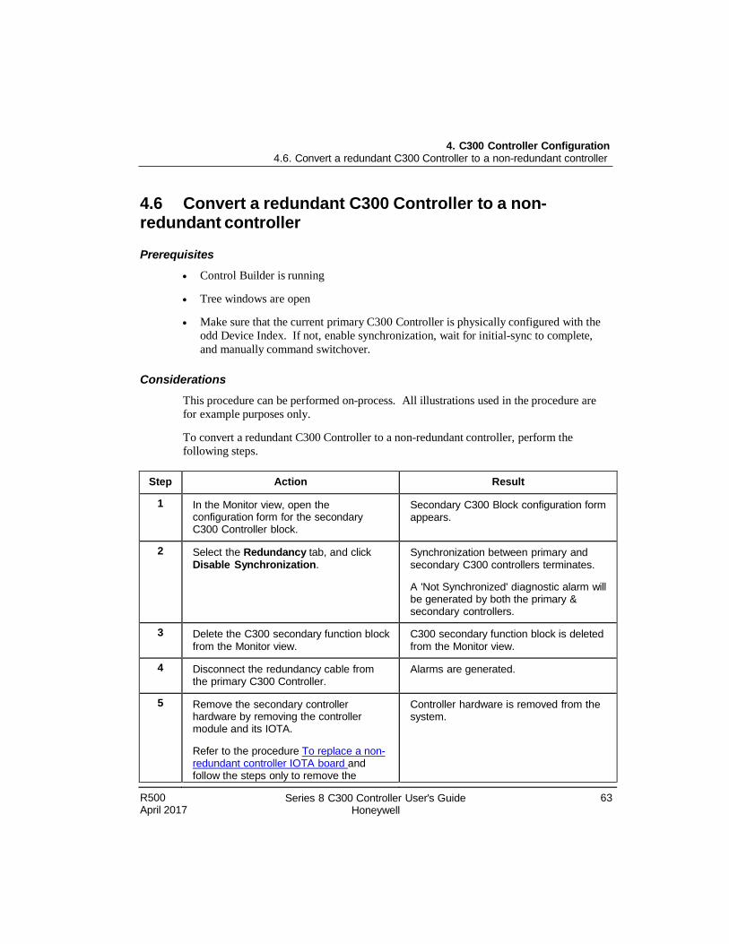
4. C300 Controller Configuration 4.6. Convert a redundant C300 Controller to a non-redundant controller
R500 April 2017
Series 8 C300 Controller User's Guide Honeywell
63
4.6 Convert a redundant C300 Controller to a non- redundant controller
Prerequisites
Control Builder is running
Tree windows are open
Make sure that the current primary C300 Controller is physically configured with the
odd Device Index. If not, enable synchronization, wait for initial-sync to complete,
and manually command switchover.
Considerations
This procedure can be performed on-process. All illustrations used in the procedure are
for example purposes only.
To convert a redundant C300 Controller to a non-redundant controller, perform the
following steps.
Step Action Result
1 In the Monitor view, open the configuration form for the secondary C300 Controller block.
Secondary C300 Block configuration form appears.
2 Select the Redundancy tab, and click Disable Synchronization.
Synchronization between primary and secondary C300 controllers terminates.
A 'Not Synchronized' diagnostic alarm will be generated by both the primary & secondary controllers.
3 Delete the C300 secondary function block from the Monitor view.
C300 secondary function block is deleted from the Monitor view.
4 Disconnect the redundancy cable from the primary C300 Controller.
Alarms are generated.
5 Remove the secondary controller hardware by removing the controller module and its IOTA.
Refer to the procedure To replace a non- redundant controller IOTA board and follow the steps only to remove the
Controller hardware is removed from the system.
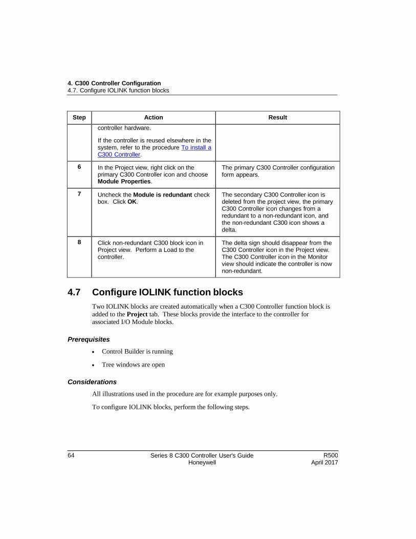
64 Series 8 C300 Controller User's Guide Honeywell
R500 April 2017
4. C300 Controller Configuration 4.7. Configure IOLINK function blocks
Step Action Result
controller hardware.
If the controller is reused elsewhere in the system, refer to the procedure To install a C300 Controller.
6 In the Project view, right click on the primary C300 Controller icon and choose Module Properties.
The primary C300 Controller configuration form appears.
7 Uncheck the Module is redundant check box. Click OK.
The secondary C300 Controller icon is deleted from the project view, the primary C300 Controller icon changes from a redundant to a non-redundant icon, and the non-redundant C300 icon shows a delta.
8 Click non-redundant C300 block icon in Project view. Perform a Load to the controller.
The delta sign should disappear from the C300 Controller icon in the Project view. The C300 Controller icon in the Monitor view should indicate the controller is now non-redundant.
4.7 Configure IOLINK function blocks
Two IOLINK blocks are created automatically when a C300 Controller function block is
added to the Project tab. These blocks provide the interface to the controller for associated I/O Module blocks.
Prerequisites
Control Builder is running
Tree windows are open
Considerations
All illustrations used in the procedure are for example purposes only.
To configure IOLINK blocks, perform the following steps.
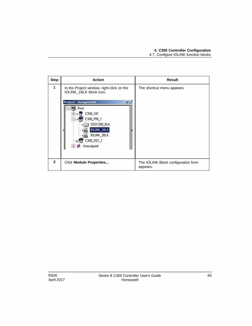
R500 April 2017
Series 8 C300 Controller User's Guide Honeywell
65
4. C300 Controller Configuration 4.7. Configure IOLINK function blocks
Step Action Result
1 In the Project window, right-click on the IOLINK_1BLK block icon.
The shortcut menu appears.
2 Click Module Properties... The IOLINK Block configuration form appears.
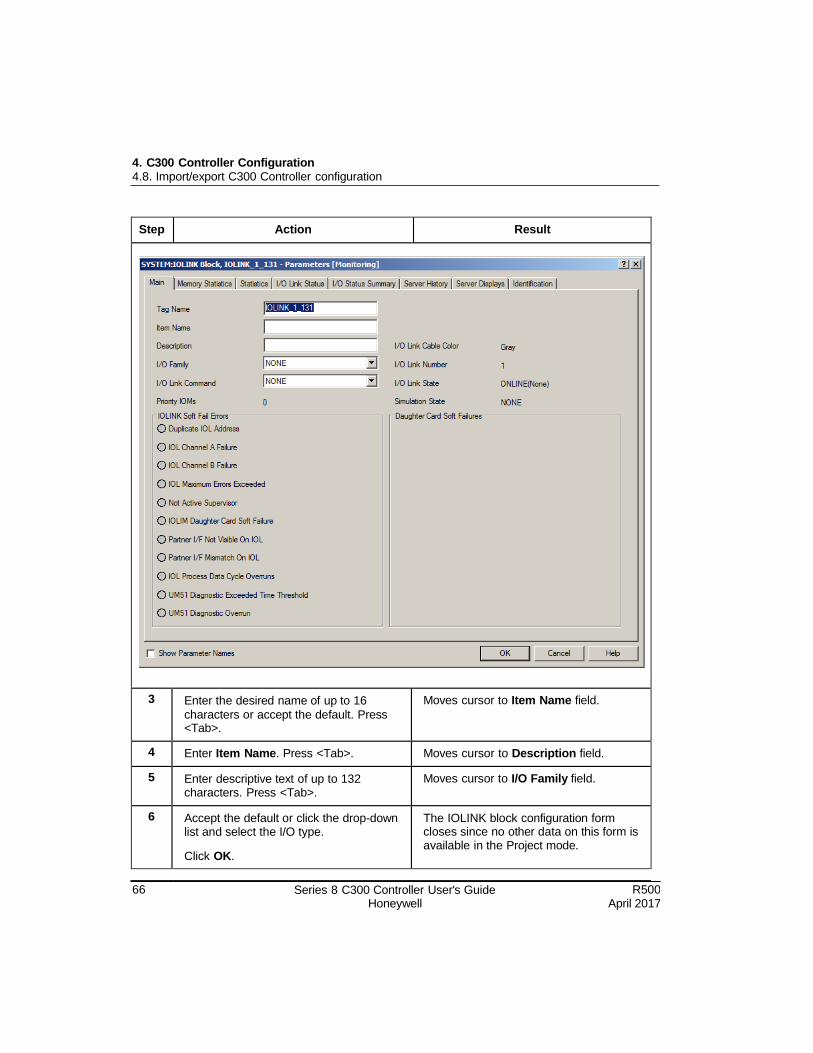
66 Series 8 C300 Controller User's Guide Honeywell
R500 April 2017
4. C300 Controller Configuration 4.8. Import/export C300 Controller configuration
Step Action Result
3 Enter the desired name of up to 16
characters or accept the default. Press <Tab>.
Moves cursor to Item Name field.
4 Enter Item Name. Press <Tab>. Moves cursor to Description field.
5 Enter descriptive text of up to 132 characters. Press <Tab>.
Moves cursor to I/O Family field.
6 Accept the default or click the drop-down list and select the I/O type.
Click OK.
The IOLINK block configuration form closes since no other data on this form is available in the Project mode.
R500 April 2017
Series 8 C300 Controller User's Guide Honeywell
67
4. C300 Controller Configuration 4.8. Import/export C300 Controller configuration
Step Action Result
7 Repeat this procedure from step 1 to configure other IOLINK blocks.
4.8 Import/export C300 Controller configuration
You can copy a C300 Controller configuration from another system database using the
Export and Import function in Control Builder.
ATTENTION It is recommended that you use the ERDB Database Migration tool rather than Import/Export for moving hardware definitions like C300 and Series 8 FIM.
Use "Export/Import" only to move or copy control strategies (CMs & SCMs) from one
system to another.
When using the export function the Device Index information for the C300 is exported,
but not the controller's IP Address. This enables import of the C300's configuration into
a different server cluster, and allows the C300 to use a different IP Address based upon
that server cluster's base IP Address.
4.9 Reset Device Index and IP address of a controller
Once set, a C300 Controller retains the Device Index (determined by the FTE NUMBER rotary switches on the IOTA) and its assigned IP Address in the controller's non-volatile
memory.
You can change the Device Index and obtain another IP Address for the controller upon
startup. For instance, when a duplicate Device Index is discovered on the same FTE
network, or when moving a controller to a different node, another FTE network, another
server domain or another system.
WARNING Be sure that the controller is in its IDLE or safe state before initiating a shutdown.
Perform the following procedure to assign a new Device Index and IP Address to a
controller installed in the system.
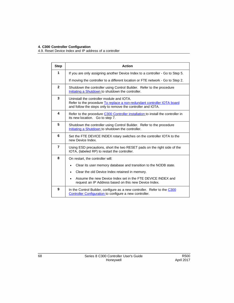
68 Series 8 C300 Controller User's Guide Honeywell
R500 April 2017
4. C300 Controller Configuration 4.9. Reset Device Index and IP address of a controller
Step Action
1 If you are only assigning another Device Index to a controller - Go to Step 5.
If moving the controller to a different location or FTE network - Go to Step 2.
2 Shutdown the controller using Control Builder. Refer to the procedure Initiating a Shutdown to shutdown the controller.
3 Uninstall the controller module and IOTA.
Refer to the procedure To replace a non-redundant controller IOTA board and follow the steps only to remove the controller and IOTA.
4 Refer to the procedure C300 Controller installation to install the controller in its new location. Go to step 7.
5 Shutdown the controller using Control Builder. Refer to the procedure Initiating a Shutdown to shutdown the controller.
6 Set the FTE DEVICE INDEX rotary switches on the controller IOTA to the new Device Index.
7 Using ESD precautions, short the two RESET pads on the right side of the IOTA, (labeled RP) to restart the controller.
8 On restart, the controller will:
Clear its user memory database and transition to the NODB state.
Clear the old Device Index retained in memory.
Assume the new Device Index set in the FTE DEVICE INDEX and request an IP Address based on this new Device Index.
9 In the Control Builder, configure as a new controller. Refer to the C300 Controller Configuration to configure a new controller.
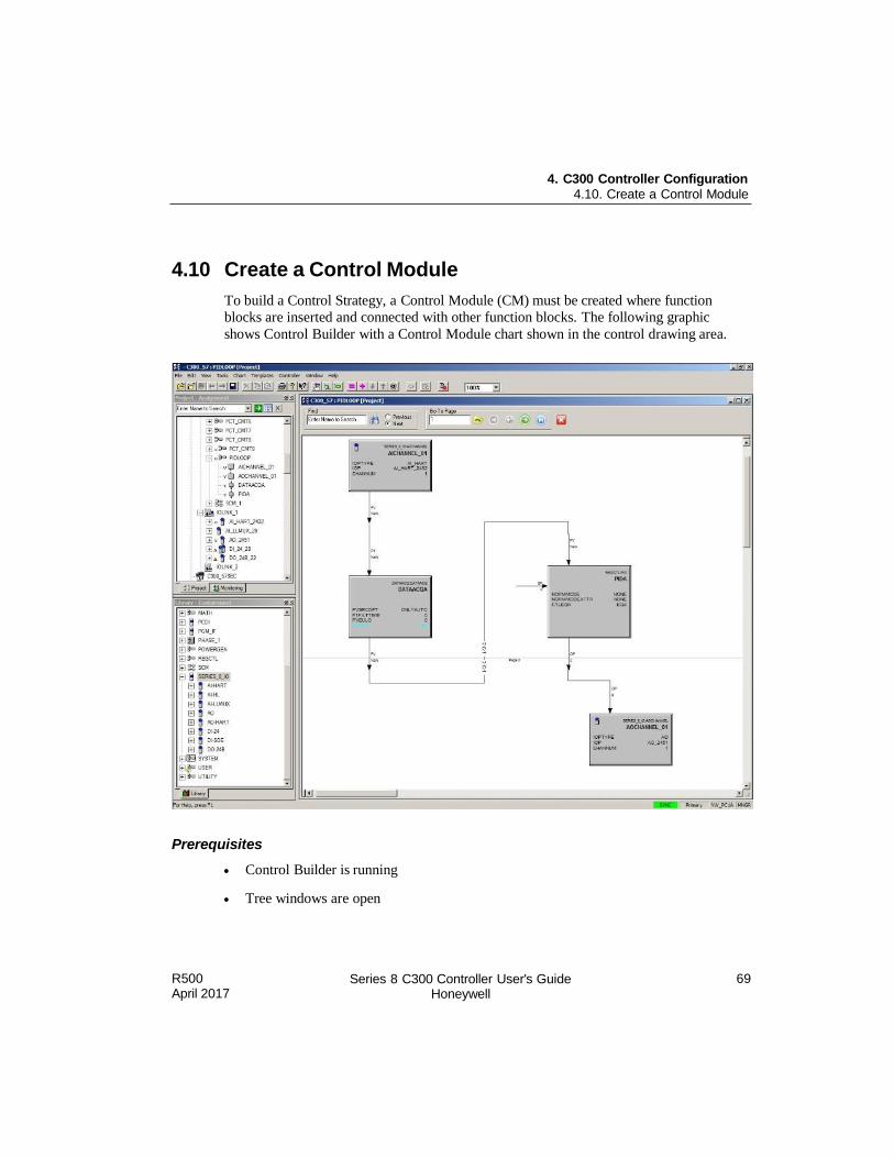
R500 April 2017
Series 8 C300 Controller User's Guide Honeywell
69
4. C300 Controller Configuration 4.10. Create a Control Module
4.10 Create a Control Module
To build a Control Strategy, a Control Module (CM) must be created where function
blocks are inserted and connected with other function blocks. The following graphic
shows Control Builder with a Control Module chart shown in the control drawing area.
Prerequisites
Control Builder is running
Tree windows are open
4. C300 Controller Configuration 4.10. Create a Control Module
70 Series 8 C300 Controller User's Guide Honeywell
R500 April 2017
Considerations
All illustrations used in the procedure are for example purposes only.
WARNING All edits done on project-related objects must be reloaded to the controller before those edits can be seen in the controller. Refer to the Control Strategy Loading for information on how to load control strategy objects.
To create and save a Control Module, perform the following steps.
Step Action
1 Click File > New > Control Module
A blank Control Module is opened up in the Control Drawing area, (shown in the figure above).
The new Control Module appears under the Unassigned Project Tree. Control Module names are sequentially numbered (for example, CM_30, CM_31,and so on).
The new Control Module is automatically saved to your hard drive.
2 Select Edit > Module Properties… or double-click inside the chart to open the Control Module parameter configuration form for input.
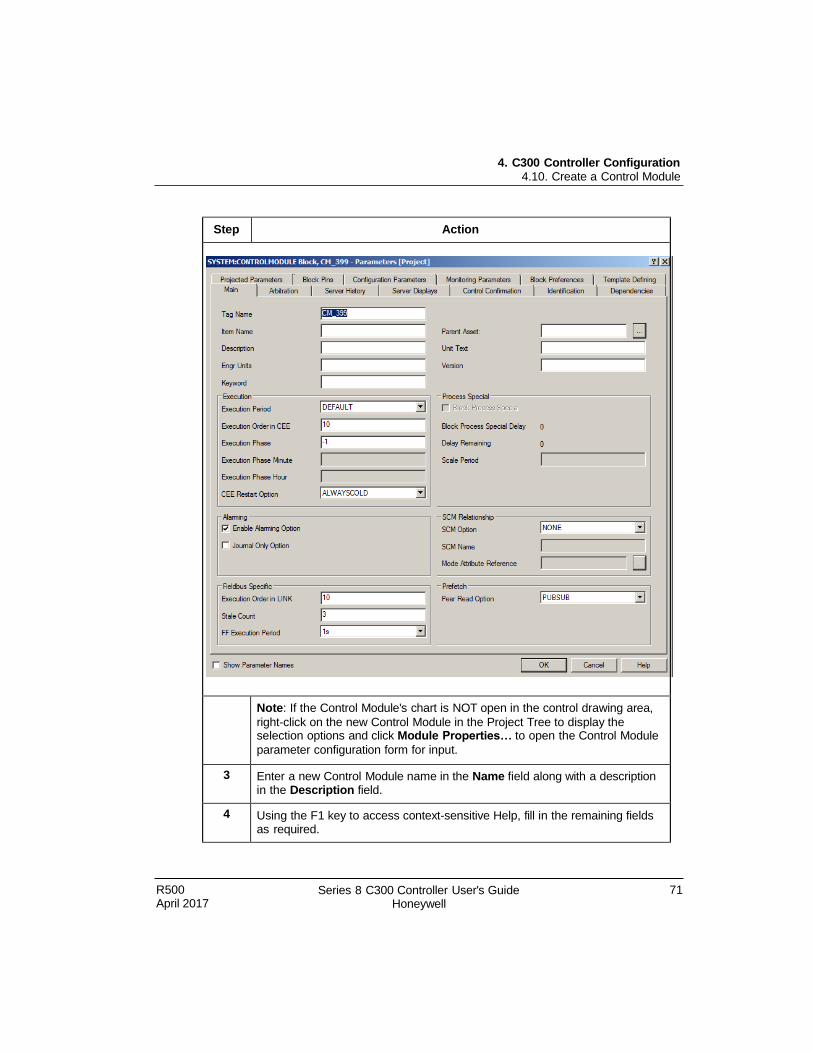
4. C300 Controller Configuration 4.10. Create a Control Module
R500 April 2017
Series 8 C300 Controller User's Guide Honeywell
71
Step Action
Note: If the Control Module's chart is NOT open in the control drawing area,
right-click on the new Control Module in the Project Tree to display the selection options and click Module Properties… to open the Control Module
parameter configuration form for input.
3 Enter a new Control Module name in the Name field along with a description in the Description field.
4 Using the F1 key to access context-sensitive Help, fill in the remaining fields as required.
4. C300 Controller Configuration 4.11. Assign Control Modules and IOMs to a CEEC300 block
72 Series 8 C300 Controller User's Guide Honeywell
R500 April 2017
Step Action
5 Click OK.
Configuration form closes.
6 If necessary, double-click on the newly-named Control Module in the Project Tree to open it. The new name appears at the top of the Control Module drawing when the control drawing opens.
7 Click File > Save to save any additional changes you make to the Control
Module before closing.
8 Click File > Close to close the chart.
4.11 Assign Control Modules and IOMs to a CEEC300 block
Once a Control Module (CM) or Sequential Control Module (SCM) is created, you can
assign it to a CEEC300 block of a C300 Controller. Use the following procedure as a
general guide to assign configured CMs and I/O Modules (IOMs) to the CEEC300 block.
Note that in the C300 controller environment can be assigned only to the CEEC300
block.
Prerequisites
Control Builder is running
Tree windows are open
Considerations
All illustrations used in the procedure are for example purposes only.
For additional information on CM assignment, refer to the Control Building Users Guide;
or for SCM assignment, the Sequential Control User's Guide.
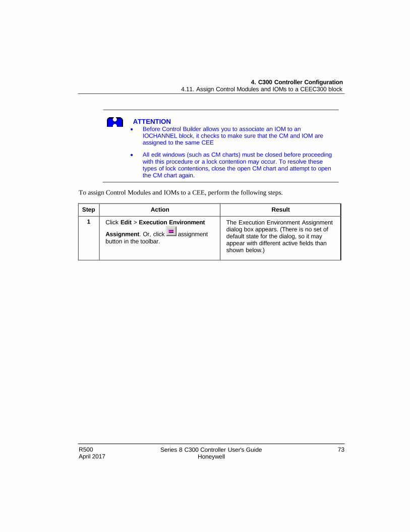
4. C300 Controller Configuration 4.11. Assign Control Modules and IOMs to a CEEC300 block
R500 April 2017
Series 8 C300 Controller User's Guide Honeywell
73
ATTENTION Before Control Builder allows you to associate an IOM to an
IOCHANNEL block, it checks to make sure that the CM and IOM are assigned to the same CEE
All edit windows (such as CM charts) must be closed before proceeding with this procedure or a lock contention may occur. To resolve these types of lock contentions, close the open CM chart and attempt to open the CM chart again.
To assign Control Modules and IOMs to a CEE, perform the following steps.
Step Action Result
1 Click Edit > Execution Environment
Assignment. Or, click assignment
button in the toolbar.
The Execution Environment Assignment dialog box appears. (There is no set of default state for the dialog, so it may appear with different active fields than shown below.)
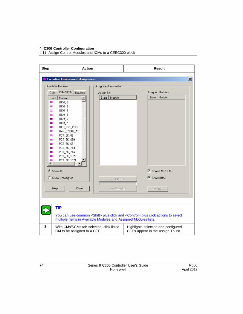
4. C300 Controller Configuration 4.11. Assign Control Modules and IOMs to a CEEC300 block
74 Series 8 C300 Controller User's Guide Honeywell
R500 April 2017
Step Action Result
TIP
You can use common <Shift> plus click and <Control> plus click actions to select multiple items in Available Modules and Assigned Modules lists.
2 With CMs/SCMs tab selected, click listed CM to be assigned to a CEE.
Highlights selection and configured CEEs appear in the Assign To list.
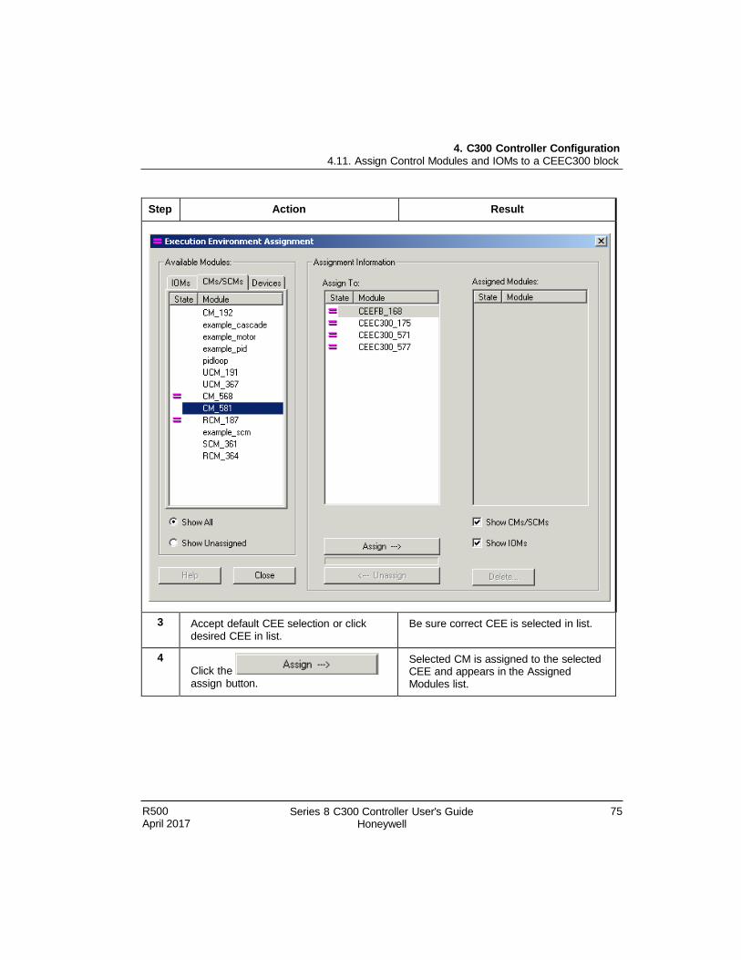
4. C300 Controller Configuration 4.11. Assign Control Modules and IOMs to a CEEC300 block
R500 April 2017
Series 8 C300 Controller User's Guide Honeywell
75
Step Action Result
3 Accept default CEE selection or click desired CEE in list.
Be sure correct CEE is selected in list.
4
Click the
assign button.
Selected CM is assigned to the selected CEE and appears in the Assigned Modules list.
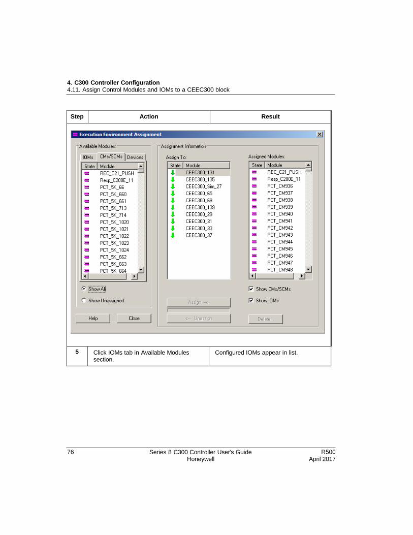
4. C300 Controller Configuration 4.11. Assign Control Modules and IOMs to a CEEC300 block
76 Series 8 C300 Controller User's Guide Honeywell
R500 April 2017
Step Action Result
5 Click IOMs tab in Available Modules section.
Configured IOMs appear in list.
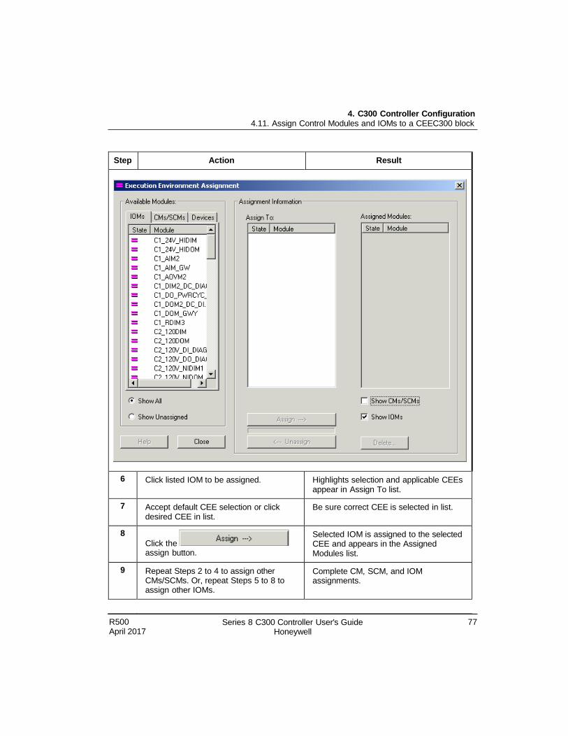
4. C300 Controller Configuration 4.11. Assign Control Modules and IOMs to a CEEC300 block
R500 April 2017
Series 8 C300 Controller User's Guide Honeywell
77
Step Action Result
6 Click listed IOM to be assigned. Highlights selection and applicable CEEs appear in Assign To list.
7 Accept default CEE selection or click desired CEE in list.
Be sure correct CEE is selected in list.
8
Click the assign button.
Selected IOM is assigned to the selected CEE and appears in the Assigned Modules list.
9 Repeat Steps 2 to 4 to assign other CMs/SCMs. Or, repeat Steps 5 to 8 to assign other IOMs.
Complete CM, SCM, and IOM assignments.
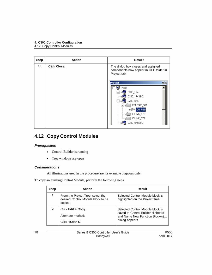
78 Series 8 C300 Controller User's Guide Honeywell
R500 April 2017
4. C300 Controller Configuration 4.12. Copy Control Modules
Step Action Result
10 Click Close. The dialog box closes and assigned components now appear in CEE folder in Project tab.
4.12 Copy Control Modules
Prerequisites
Control Builder is running
Tree windows are open
Considerations
All illustrations used in the procedure are for example purposes only.
To copy an existing Control Module, perform the following steps.
Step Action Result
1 From the Project Tree, select the desired Control Module block to be copied.
Selected Control Module block is highlighted on the Project Tree.
2 Click Edit > Copy.
Alternate method:
Click <Ctrl>-C.
Selected Control Module block is saved to Control Builder clipboard and Name New Function Block(s)… dialog appears.
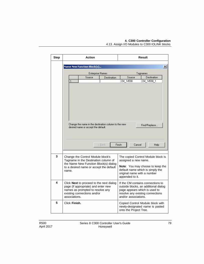
R500 April 2017
Series 8 C300 Controller User's Guide Honeywell
79
4. C300 Controller Configuration 4.13. Assign I/O Modules to C300 IOLINK blocks
Step Action Result
3 Change the Control Module block's Tagname in the Destination column of the Name New Function Block(s) dialog to a desired name or accept the default name.
The copied Control Module block is assigned a new name.
Note: You may choose to keep the
default name which is simply the original name with a number appended to it.
4 Click Next to proceed to the next dialog page (if appropriate) and enter new names as prompted to resolve any existing connections and/or associations.
If the CM contains connections to outside blocks, an additional dialog page appears which is used to resolve any existing connections and/or associations.
5 Click Finish. Copied Control Module block with newly-designated name is pasted onto the Project Tree.
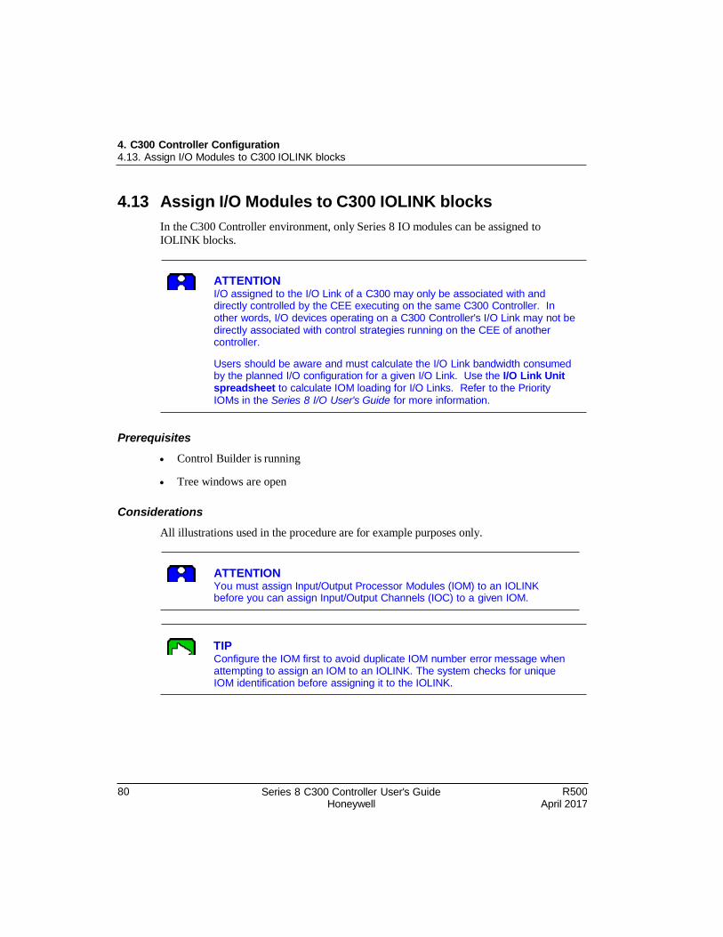
4. C300 Controller Configuration 4.13. Assign I/O Modules to C300 IOLINK blocks
80 Series 8 C300 Controller User's Guide Honeywell
R500 April 2017
4.13 Assign I/O Modules to C300 IOLINK blocks
In the C300 Controller environment, only Series 8 IO modules can be assigned to
IOLINK blocks.
ATTENTION I/O assigned to the I/O Link of a C300 may only be associated with and directly controlled by the CEE executing on the same C300 Controller. In other words, I/O devices operating on a C300 Controller's I/O Link may not be directly associated with control strategies running on the CEE of another controller.
Users should be aware and must calculate the I/O Link bandwidth consumed by the planned I/O configuration for a given I/O Link. Use the I/O Link Unit spreadsheet to calculate IOM loading for I/O Links. Refer to the Priority IOMs in the Series 8 I/O User's Guide for more information.
Prerequisites
Control Builder is running
Tree windows are open
Considerations
All illustrations used in the procedure are for example purposes only.
ATTENTION You must assign Input/Output Processor Modules (IOM) to an IOLINK before you can assign Input/Output Channels (IOC) to a given IOM.
TIP Configure the IOM first to avoid duplicate IOM number error message when attempting to assign an IOM to an IOLINK. The system checks for unique IOM identification before assigning it to the IOLINK.
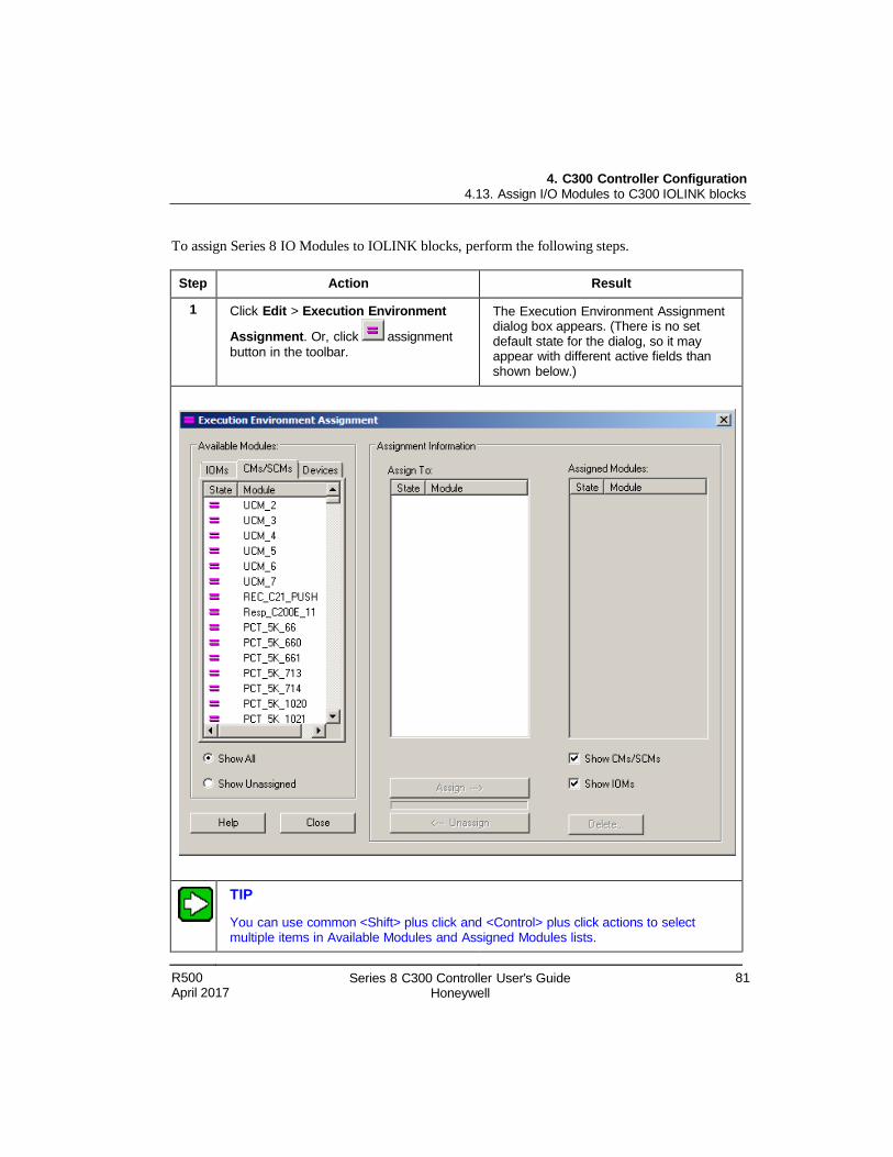
4. C300 Controller Configuration 4.13. Assign I/O Modules to C300 IOLINK blocks
R500 April 2017
Series 8 C300 Controller User's Guide Honeywell
81
To assign Series 8 IO Modules to IOLINK blocks, perform the following steps.
Step Action Result
1 Click Edit > Execution Environment
Assignment. Or, click assignment
button in the toolbar.
The Execution Environment Assignment dialog box appears. (There is no set default state for the dialog, so it may appear with different active fields than shown below.)
TIP
You can use common <Shift> plus click and <Control> plus click actions to select multiple items in Available Modules and Assigned Modules lists.
4. C300 Controller Configuration 4.13. Assign I/O Modules to C300 IOLINK blocks
82 Series 8 C300 Controller User's Guide Honeywell
R500 April 2017
2 With IOMs tab selected, click desired IOM to be assigned to given IOLINK.
Highlights selection and configured IOLINKs appear in the Assign To list.
3 Accept default IOLINK selection or click desired IOLINK in list.
Be sure correct IOLINK is selected in list.
4
Click the assign button.
Selected IOM is assigned to the selected IOLINK and appears in the Assigned Modules list.
Note: You may need to select the
IOLINK in the list to view the IOM just assigned to it.
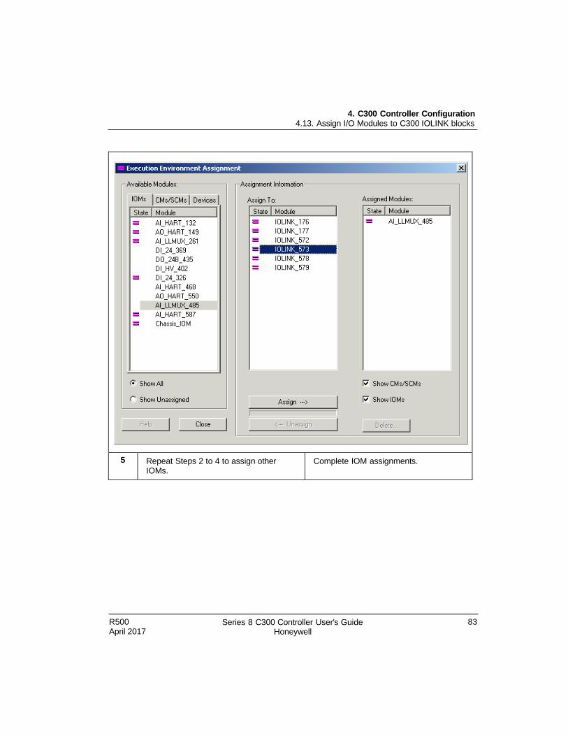
4. C300 Controller Configuration 4.13. Assign I/O Modules to C300 IOLINK blocks
R500 April 2017
Series 8 C300 Controller User's Guide Honeywell
83
5 Repeat Steps 2 to 4 to assign other IOMs.
Complete IOM assignments.
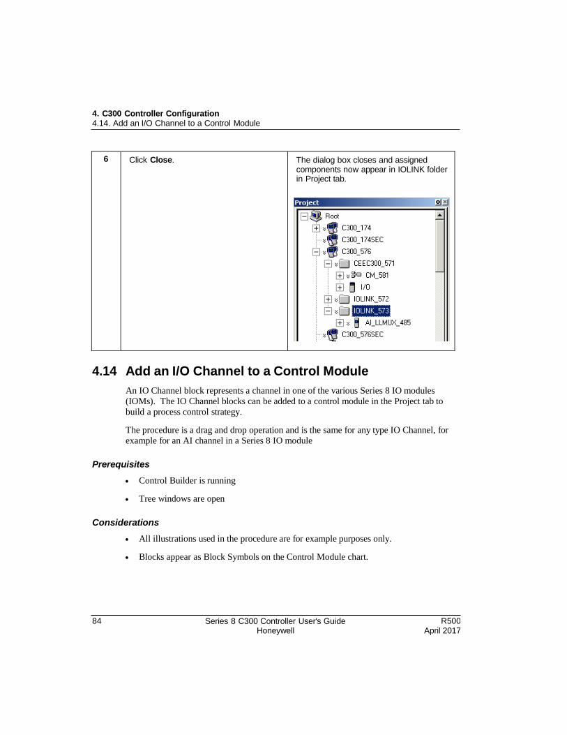
84 Series 8 C300 Controller User's Guide Honeywell
R500 April 2017
4. C300 Controller Configuration 4.14. Add an I/O Channel to a Control Module
6 Click Close. The dialog box closes and assigned components now appear in IOLINK folder in Project tab.
4.14 Add an I/O Channel to a Control Module
An IO Channel block represents a channel in one of the various Series 8 IO modules
(IOMs). The IO Channel blocks can be added to a control module in the Project tab to
build a process control strategy.
The procedure is a drag and drop operation and is the same for any type IO Channel, for
example for an AI channel in a Series 8 IO module
Prerequisites
Control Builder is running
Tree windows are open
Considerations
All illustrations used in the procedure are for example purposes only.
Blocks appear as Block Symbols on the Control Module chart.
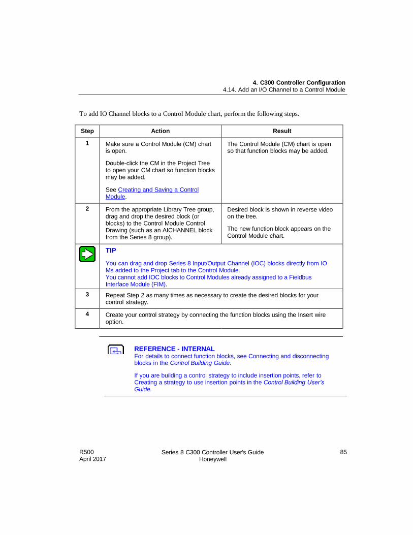
R500 April 2017
Series 8 C300 Controller User's Guide Honeywell
85
4. C300 Controller Configuration 4.14. Add an I/O Channel to a Control Module
To add IO Channel blocks to a Control Module chart, perform the following steps.
Step Action Result
1 Make sure a Control Module (CM) chart is open.
Double-click the CM in the Project Tree to open your CM chart so function blocks may be added.
See Creating and Saving a Control Module.
The Control Module (CM) chart is open so that function blocks may be added.
2 From the appropriate Library Tree group, drag and drop the desired block (or blocks) to the Control Module Control Drawing (such as an AICHANNEL block from the Series 8 group).
Desired block is shown in reverse video on the tree.
The new function block appears on the Control Module chart.
TIP
You can drag and drop Series 8 Input/Output Channel (IOC) blocks directly from IO Ms added to the Project tab to the Control Module. You cannot add IOC blocks to Control Modules already assigned to a Fieldbus Interface Module (FIM).
3 Repeat Step 2 as many times as necessary to create the desired blocks for your control strategy.
4 Create your control strategy by connecting the function blocks using the Insert wire option.
REFERENCE - INTERNAL For details to connect function blocks, see Connecting and disconnecting blocks in the Control Building Guide.
If you are building a control strategy to include insertion points, refer to Creating a strategy to use insertion points in the Control Building User’s Guide.

R500 April 2017
Series 8 C300 Controller User's Guide Honeywell
87
5. C300 Configuration Form Reference
This chapter describes the summary of the user visible parameters for a C300 Controller
and its associated blocks, (Secondary C300, CEEC300, and IOLINK blocks). The
parameters are grouped according to the tab where they reside on the configuration form.
For more details on these parameters see the Control Builder Parameter Reference.
The following table provides the sections covered in this chapter. Click the topic to view it.
Topic
C300 Controller block
Secondary C300 block
CEEC300 function block
IOLINK block
Note: Since migration is not supported in this release, parameters related to OPM are not
applicable.
5.1 C300 Controller Block
Main tab
The Main Tab is used to configure (and display configuration of) the C300 Controller.
Refer to the To configure a C300 Controller block for the steps to configure a C300
Controller block. The Main tab contains most of the parameters that must be configured
when setting up a C300 Controller. It also displays the important states of the C300
Controller and supports the key commands associated with C300 Controller operation.
Location and Redundancy configuration can be entered only in the Project Tree. The
following table summarizes the parameter data you can monitor and/or configure on the
Main tab of the configuration form for the selected C300 block.
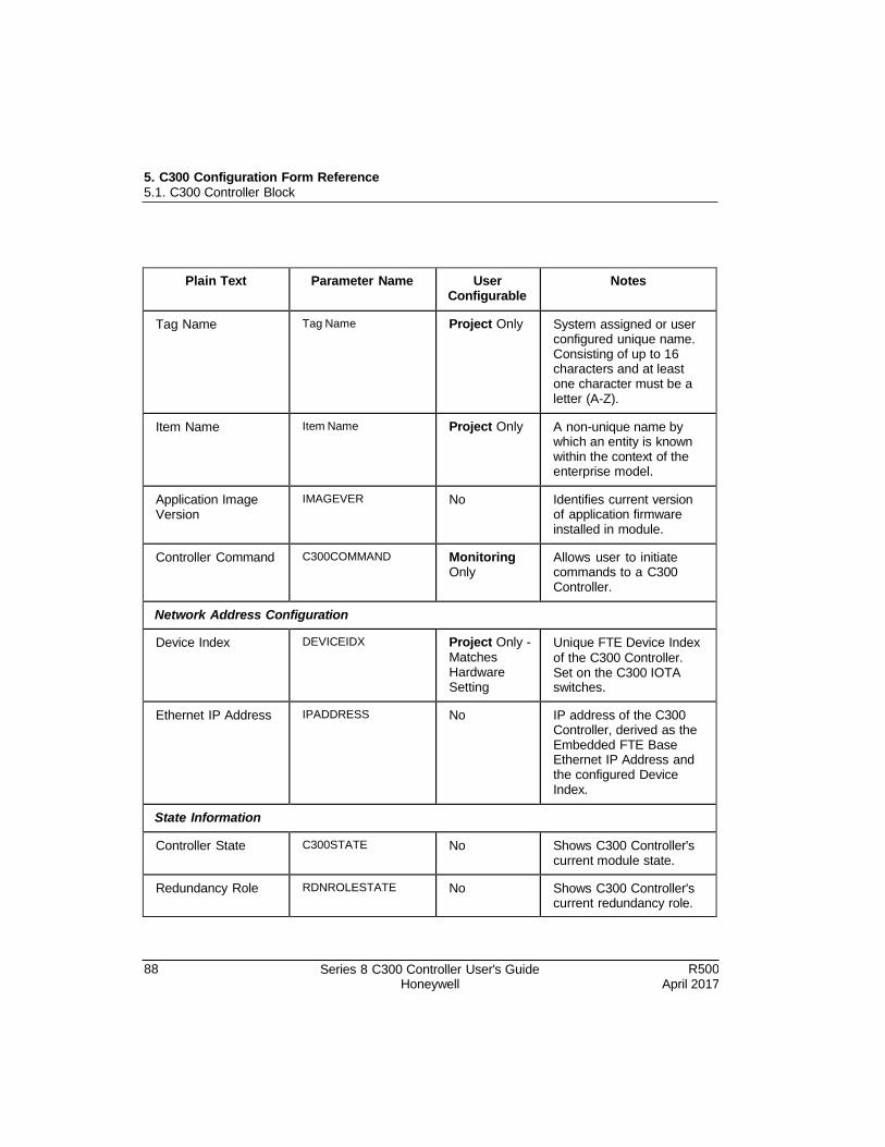
88 Series 8 C300 Controller User's Guide Honeywell
R500 April 2017
5. C300 Configuration Form Reference 5.1. C300 Controller Block
Plain Text Parameter Name User Configurable
Notes
Tag Name Tag Name Project Only System assigned or user configured unique name. Consisting of up to 16 characters and at least one character must be a letter (A-Z).
Item Name Item Name Project Only A non-unique name by which an entity is known within the context of the enterprise model.
Application Image Version
IMAGEVER No Identifies current version of application firmware installed in module.
Controller Command C300COMMAND Monitoring Only
Allows user to initiate commands to a C300 Controller.
Network Address Configuration
Device Index DEVICEIDX Project Only - Matches Hardware Setting
Unique FTE Device Index
of the C300 Controller. Set on the C300 IOTA switches.
Ethernet IP Address IPADDRESS No IP address of the C300 Controller, derived as the Embedded FTE Base Ethernet IP Address and the configured Device Index.
State Information
Controller State C300STATE No Shows C300 Controller's current module state.
Redundancy Role RDNROLESTATE No Shows C300 Controller's current redundancy role.
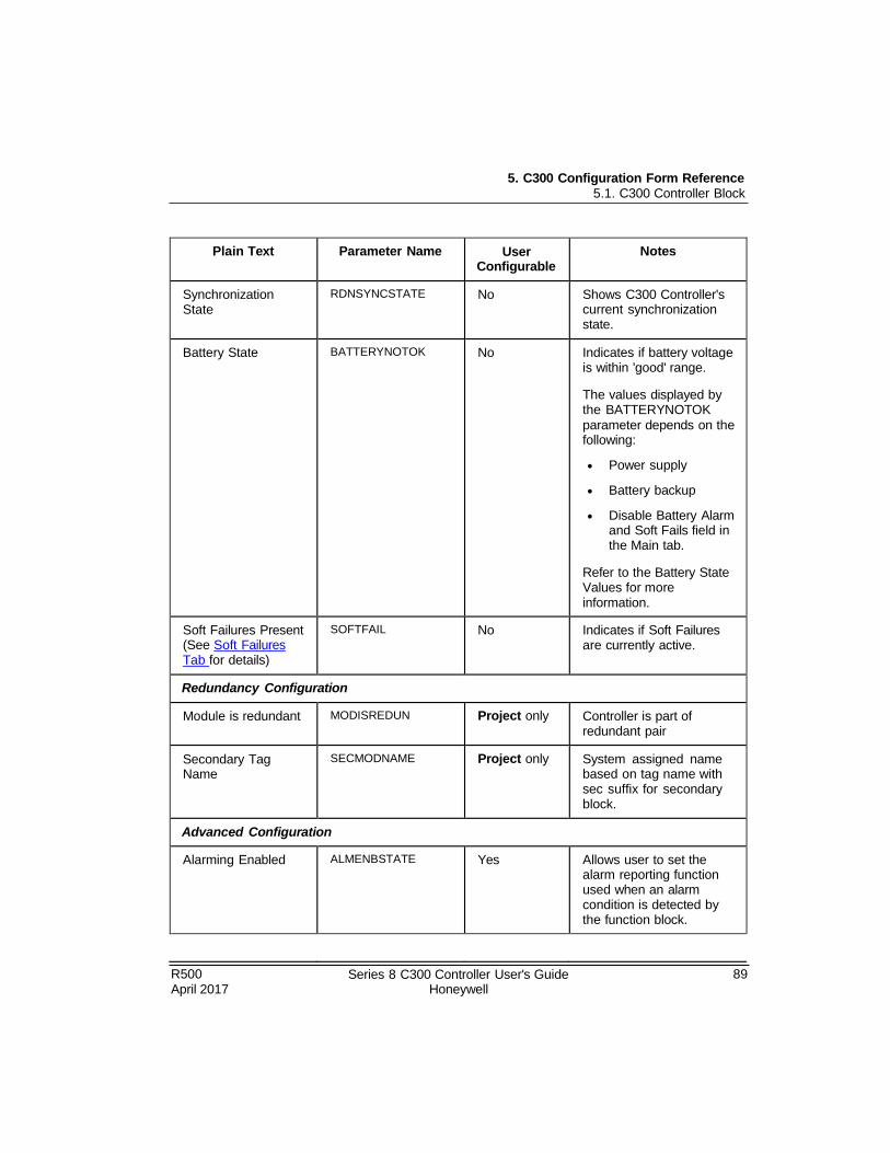
R500 April 2017
Series 8 C300 Controller User's Guide Honeywell
89
5. C300 Configuration Form Reference 5.1. C300 Controller Block
Plain Text Parameter Name User Configurable
Notes
Synchronization State
RDNSYNCSTATE No Shows C300 Controller's current synchronization state.
Battery State BATTERYNOTOK No Indicates if battery voltage is within 'good' range.
The values displayed by the BATTERYNOTOK
parameter depends on the following:
Power supply
Battery backup
Disable Battery Alarm and Soft Fails field in the Main tab.
Refer to the Battery State Values for more information.
Soft Failures Present (See Soft Failures Tab for details)
SOFTFAIL No Indicates if Soft Failures are currently active.
Redundancy Configuration
Module is redundant MODISREDUN Project only Controller is part of redundant pair
Secondary Tag Name
SECMODNAME Project only System assigned name based on tag name with sec suffix for secondary block.
Advanced Configuration
Alarming Enabled ALMENBSTATE Yes Allows user to set the alarm reporting function used when an alarm condition is detected by the function block.
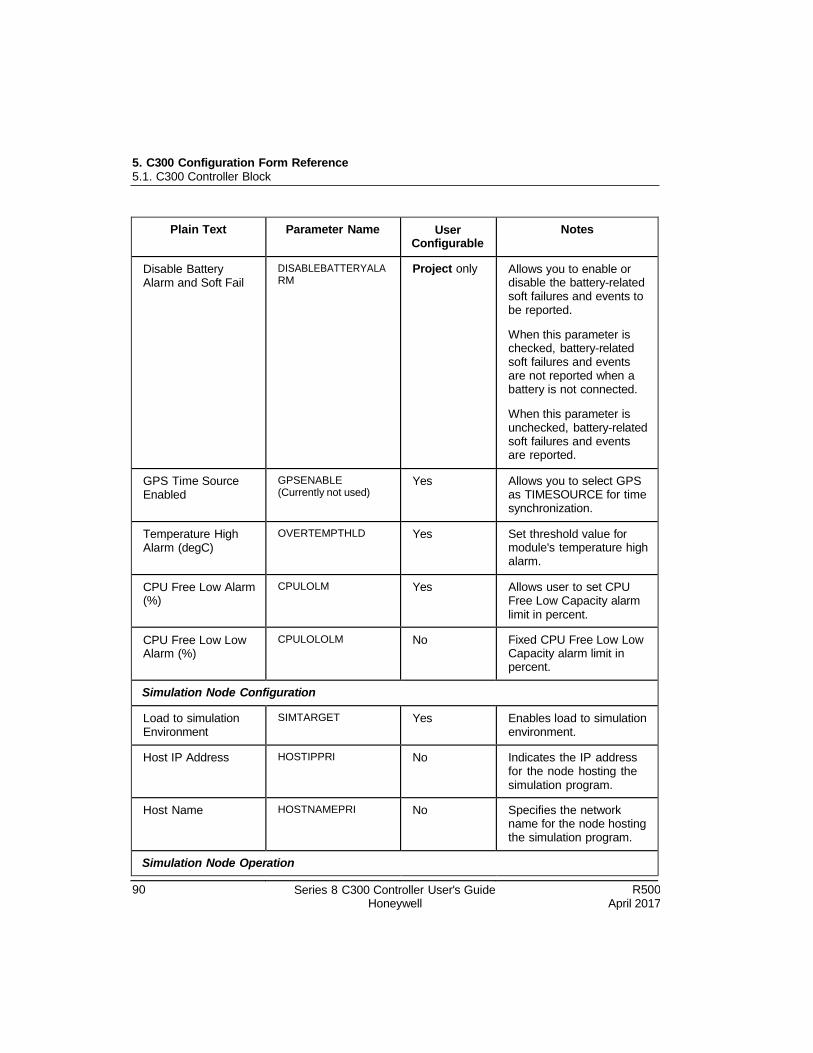
5. C300 Configuration Form Reference 5.1. C300 Controller Block
90 Series 8 C300 Controller User's Guide Honeywell
R500 April 2017
Plain Text Parameter Name User Configurable
Notes
Disable Battery Alarm and Soft Fail
DISABLEBATTERYALA RM
Project only Allows you to enable or disable the battery-related soft failures and events to be reported.
When this parameter is checked, battery-related soft failures and events are not reported when a battery is not connected.
When this parameter is unchecked, battery-related soft failures and events are reported.
GPS Time Source Enabled
GPSENABLE (Currently not used)
Yes Allows you to select GPS as TIMESOURCE for time synchronization.
Temperature High Alarm (degC)
OVERTEMPTHLD Yes Set threshold value for module's temperature high alarm.
CPU Free Low Alarm (%)
CPULOLM Yes Allows user to set CPU Free Low Capacity alarm limit in percent.
CPU Free Low Low Alarm (%)
CPULOLOLM No Fixed CPU Free Low Low Capacity alarm limit in percent.
Simulation Node Configuration
Load to simulation Environment
SIMTARGET Yes Enables load to simulation environment.
Host IP Address HOSTIPPRI No Indicates the IP address for the node hosting the simulation program.
Host Name HOSTNAMEPRI No Specifies the network name for the node hosting the simulation program.
Simulation Node Operation
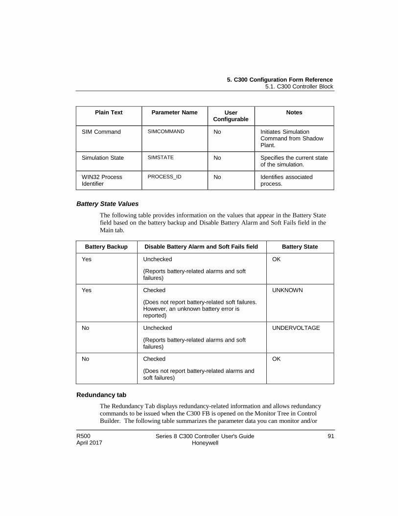
5. C300 Configuration Form Reference 5.1. C300 Controller Block
R500 April 2017
Series 8 C300 Controller User's Guide Honeywell
91
Plain Text Parameter Name User Configurable
Notes
SIM Command SIMCOMMAND No Initiates Simulation Command from Shadow Plant.
Simulation State SIMSTATE No Specifies the current state of the simulation.
WIN32 Process Identifier
PROCESS_ID No Identifies associated process.
Battery State Values
The following table provides information on the values that appear in the Battery State
field based on the battery backup and Disable Battery Alarm and Soft Fails field in the
Main tab.
Battery Backup Disable Battery Alarm and Soft Fails field Battery State
Yes Unchecked
(Reports battery-related alarms and soft failures)
OK
Yes Checked
(Does not report battery-related soft failures. However, an unknown battery error is reported)
UNKNOWN
No Unchecked
(Reports battery-related alarms and soft failures)
UNDERVOLTAGE
No Checked
(Does not report battery-related alarms and soft failures)
OK
Redundancy tab
The Redundancy Tab displays redundancy-related information and allows redundancy commands to be issued when the C300 FB is opened on the Monitor Tree in Control
Builder. The following table summarizes the parameter data you can monitor and/or
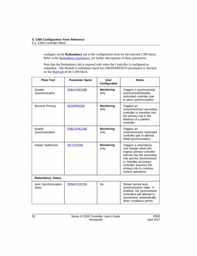
5. C300 Configuration Form Reference 5.1. C300 Controller Block
92 Series 8 C300 Controller User's Guide Honeywell
R500 April 2017
configure on the Redundancy tab of the configuration form for the selected C300 block.
Refer to the Redundancy parameters for further descriptions of these parameters.
Note that the Redundancy tab is exposed only when the Controller is configured as redundant. The Module is redundant check box (MODISREDUN parameter) is checked
on the Main tab of the C300 block.
Plain Text Parameter Name User Configurable
Notes
Disable Synchronization
DSBLSYNCCMD Monitoring only
Triggers a synchronizing/ synchronized/standby redundant controller pair to abort synchronization.
Become Primary BECMPRICMD Monitoring only
Triggers an unsynchronized secondary controller to transition into the primary role in the absence of a partner controller.
Enable Synchronization
ENBLSYNCCMD Monitoring only
Triggers an unsynchronized redundant controller pair to attempt initial-synchronization.
Initiate Switchover SW ITCHCMD Monitoring only
Triggers a redundancy role change where the original primary controller reboots into the secondary role and the Synchronized or Standby secondary controller assumes the primary role to continue control operations.
Redundancy Status
Auto Synchronization State
RDNAUTOSYNC No Shows current auto synchronization state. If enabled, not synchronized controllers will attempt to synchronize automatically when conditions permit.
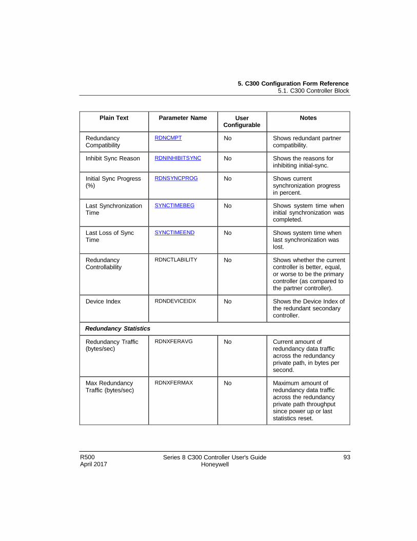
5. C300 Configuration Form Reference 5.1. C300 Controller Block
R500 April 2017
Series 8 C300 Controller User's Guide Honeywell
93
Plain Text Parameter Name User Configurable
Notes
Redundancy Compatibility
RDNCMPT No Shows redundant partner compatibility.
Inhibit Sync Reason RDNINHIBITSYNC No Shows the reasons for inhibiting initial-sync.
Initial Sync Progress (%)
RDNSYNCPROG No Shows current synchronization progress in percent.
Last Synchronization Time
SYNCTIMEBEG No Shows system time when initial synchronization was completed.
Last Loss of Sync Time
SYNCTIMEEND No Shows system time when last synchronization was lost.
Redundancy Controllability
RDNCTLABILITY No Shows whether the current controller is better, equal, or worse to be the primary controller (as compared to the partner controller).
Device Index RDNDEVICEIDX No Shows the Device Index of the redundant secondary controller.
Redundancy Statistics
Redundancy Traffic (bytes/sec)
RDNXFERAVG No Current amount of redundancy data traffic across the redundancy private path, in bytes per second.
Max Redundancy Traffic (bytes/sec)
RDNXFERMAX No Maximum amount of redundancy data traffic across the redundancy private path throughput since power up or last statistics reset.
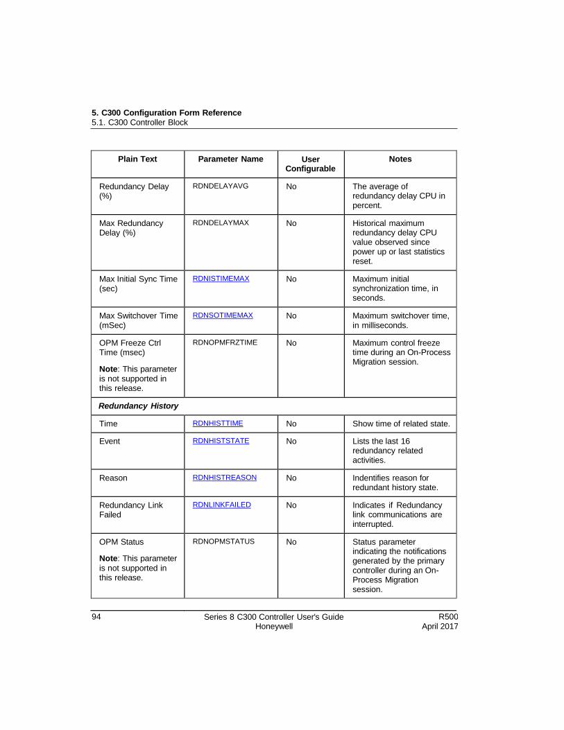
5. C300 Configuration Form Reference 5.1. C300 Controller Block
94 Series 8 C300 Controller User's Guide Honeywell
R500 April 2017
Plain Text Parameter Name User Configurable
Notes
Redundancy Delay (%)
RDNDELAYAVG No The average of redundancy delay CPU in percent.
Max Redundancy Delay (%)
RDNDELAYMAX No Historical maximum redundancy delay CPU value observed since power up or last statistics reset.
Max Initial Sync Time (sec)
RDNISTIMEMAX No Maximum initial synchronization time, in seconds.
Max Switchover Time (mSec)
RDNSOTIMEMAX No Maximum switchover time, in milliseconds.
OPM Freeze Ctrl Time (msec)
Note: This parameter is not supported in this release.
RDNOPMFRZTIME No Maximum control freeze time during an On-Process Migration session.
Redundancy History
Time RDNHISTTIME No Show time of related state.
Event RDNHISTSTATE No Lists the last 16 redundancy related activities.
Reason RDNHISTREASON No Indentifies reason for redundant history state.
Redundancy Link Failed
RDNLINKFAILED No Indicates if Redundancy link communications are interrupted.
OPM Status
Note: This parameter
is not supported in this release.
RDNOPMSTATUS No Status parameter indicating the notifications generated by the primary controller during an On- Process Migration session.
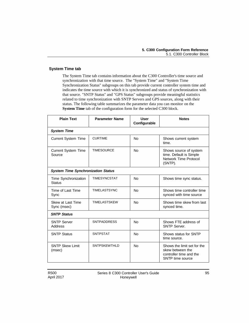
5. C300 Configuration Form Reference 5.1. C300 Controller Block
R500 April 2017
Series 8 C300 Controller User's Guide Honeywell
95
System Time tab
The System Time tab contains information about the C300 Controller's time source and
synchronization with that time source. The "System Time" and "System Time
Synchronization Status" subgroups on this tab provide current controller system time and
indicates the time source with which it is synchronized and status of synchronization with
that source. "SNTP Status" and "GPS Status" subgroups provide meaningful statistics
related to time synchronization with SNTP Servers and GPS sources, along with their
status. The following table summarizes the parameter data you can monitor on the
System Time tab of the configuration form for the selected C300 block.
Plain Text Parameter Name User Configurable
Notes
System Time
Current System Time CURTIME No Shows current system time.
Current System Time Source
TIMESOURCE No Shows source of system time. Default is Simple Network Time Protocol (SNTP).
System Time Synchronization Status
Time Synchronization Status
TIMESYNCSTAT No Shows time sync status.
Time of Last Time Sync
TIMELASTSYNC No Shows time controller time synced with time source
Skew at Last Time Sync (msec)
TIMELASTSKEW No Shows time skew from last synced time.
SNTP Status
SNTP Server Address
SNTPADDRESS No Shows FTE address of SNTP Server.
SNTP Status SNTPSTAT No Shows status for SNTP time source.
SNTP Skew Limit (msec)
SNTPSKEWTHLD No Shows the limit set for the skew between the controller time and the SNTP time source
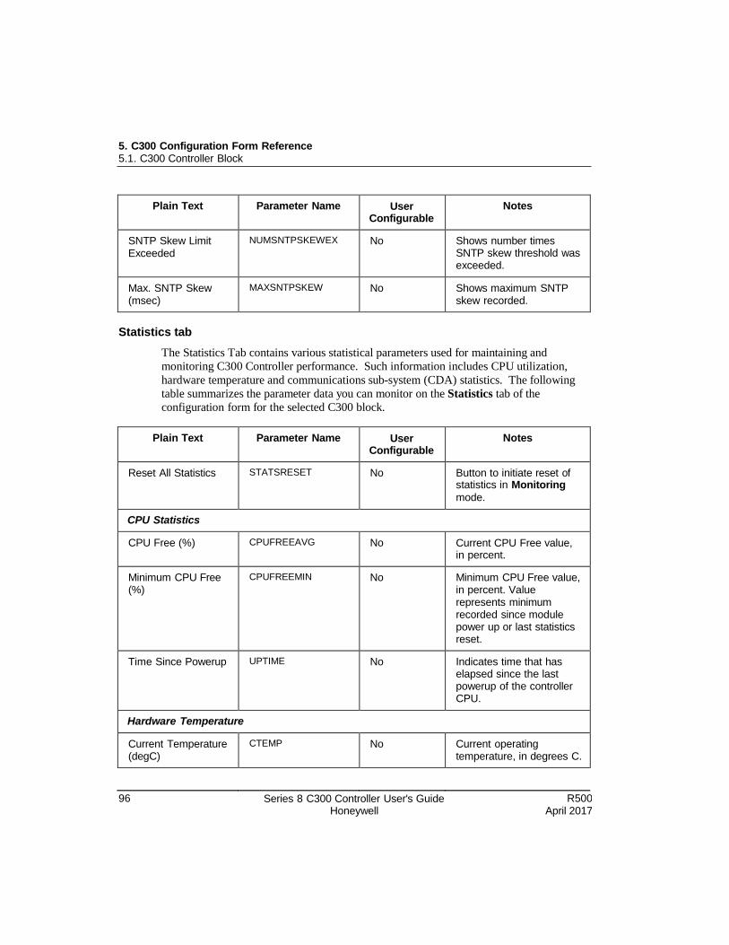
5. C300 Configuration Form Reference 5.1. C300 Controller Block
96 Series 8 C300 Controller User's Guide Honeywell
R500 April 2017
Plain Text Parameter Name User Configurable
Notes
SNTP Skew Limit Exceeded
NUMSNTPSKEWEX No Shows number times SNTP skew threshold was exceeded.
Max. SNTP Skew (msec)
MAXSNTPSKEW No Shows maximum SNTP skew recorded.
Statistics tab
The Statistics Tab contains various statistical parameters used for maintaining and
monitoring C300 Controller performance. Such information includes CPU utilization,
hardware temperature and communications sub-system (CDA) statistics. The following
table summarizes the parameter data you can monitor on the Statistics tab of the
configuration form for the selected C300 block.
Plain Text Parameter Name User Configurable
Notes
Reset All Statistics STATSRESET No Button to initiate reset of statistics in Monitoring
mode.
CPU Statistics
CPU Free (%) CPUFREEAVG No Current CPU Free value, in percent.
Minimum CPU Free (%)
CPUFREEMIN No Minimum CPU Free value, in percent. Value represents minimum recorded since module power up or last statistics reset.
Time Since Powerup UPTIME No Indicates time that has elapsed since the last powerup of the controller CPU.
Hardware Temperature
Current Temperature (degC)
CTEMP No Current operating temperature, in degrees C.
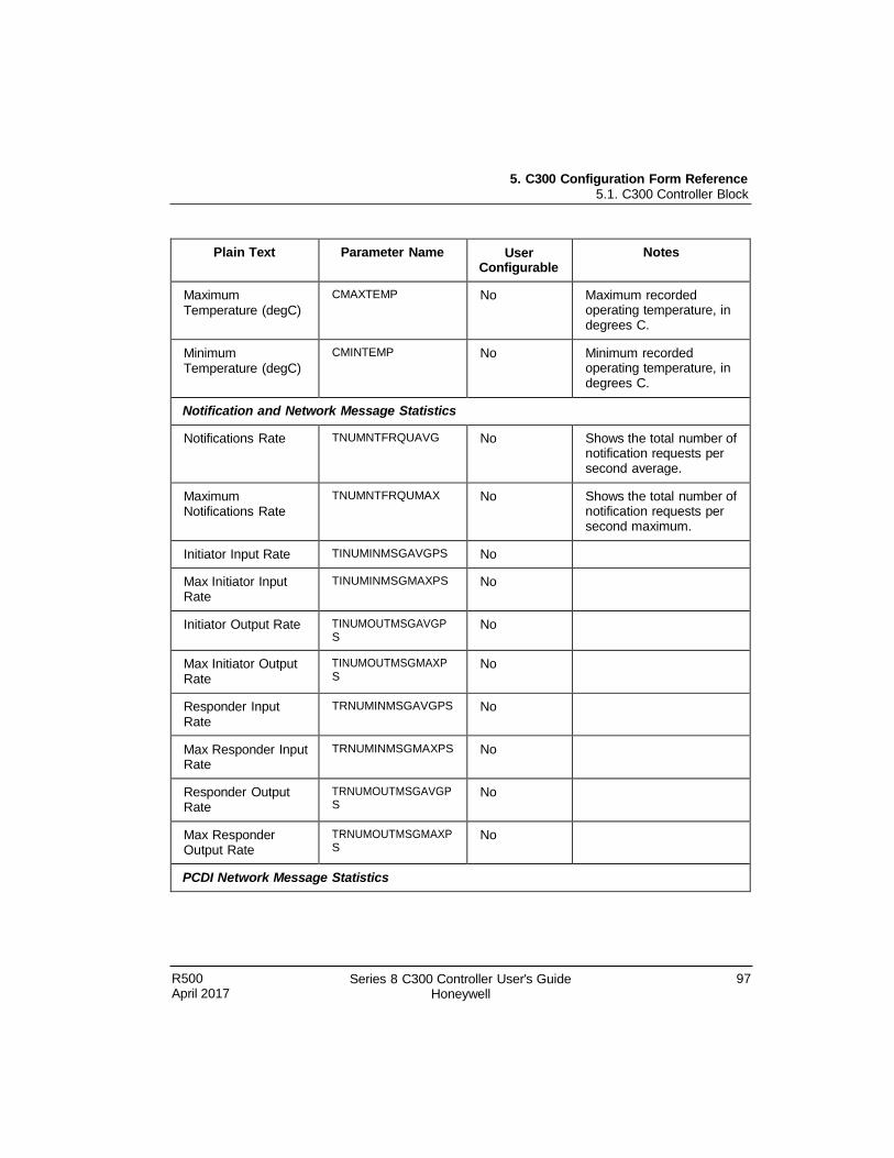
5. C300 Configuration Form Reference 5.1. C300 Controller Block
R500 April 2017
Series 8 C300 Controller User's Guide Honeywell
97
Plain Text Parameter Name User Configurable
Notes
Maximum Temperature (degC)
CMAXTEMP No Maximum recorded operating temperature, in degrees C.
Minimum Temperature (degC)
CMINTEMP No Minimum recorded operating temperature, in degrees C.
Notification and Network Message Statistics
Notifications Rate TNUMNTFRQUAVG No Shows the total number of notification requests per second average.
Maximum Notifications Rate
TNUMNTFRQUMAX No Shows the total number of notification requests per second maximum.
Initiator Input Rate TINUMINMSGAVGPS No
Max Initiator Input Rate
TINUMINMSGMAXPS No
Initiator Output Rate TINUMOUTMSGAVGP S
No
Max Initiator Output Rate
TINUMOUTMSGMAXP S
No
Responder Input Rate
TRNUMINMSGAVGPS No
Max Responder Input Rate
TRNUMINMSGMAXPS No
Responder Output Rate
TRNUMOUTMSGAVGP S
No
Max Responder Output Rate
TRNUMOUTMSGMAXP S
No
PCDI Network Message Statistics
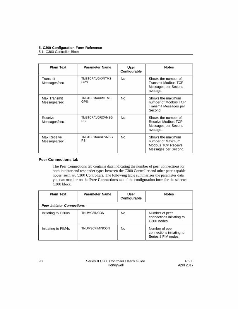
5. C300 Configuration Form Reference 5.1. C300 Controller Block
98 Series 8 C300 Controller User's Guide Honeywell
R500 April 2017
Plain Text Parameter Name User Configurable
Notes
Transmit Messages/sec
TMBTCPAVGXMITMS GPS
No Shows the number of Transmit Modbus TCP Messages per Second average.
Max Transmit Messages/sec
TMBTCPMAXXMITMS GPS
No Shows the maximum number of Modbus TCP Transmit Messages per Second.
Receive Messages/sec
TMBTCPAVGRCVMSG PS
No Shows the number of Receive Modbus TCP Messages per Second average.
Max Receive Messages/sec
TMBTCPMAXRCVMSG PS
No Shows the maximum number of Maximum Modbus TCP Receive Messages per Second.
Peer Connections tab
The Peer Connections tab contains data indicating the number of peer connections for
both initiator and responder types between the C300 Controller and other peer-capable
nodes, such as, C300 Controllers. The following table summarizes the parameter data
you can monitor on the Peer Connections tab of the configuration form for the selected
C300 block.
Plain Text Parameter Name User Configurable
Notes
Peer Initiator Connections
Initiating to C300s TNUMC3INCON No Number of peer connections initiating to C300 nodes.
Initiating to FIM4s TNUMSCFIMINCON No Number of peer connections initiating to Series 8 FIM nodes.
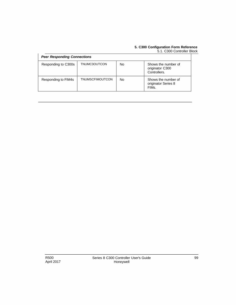
5. C300 Configuration Form Reference 5.1. C300 Controller Block
R500 April 2017
Series 8 C300 Controller User's Guide Honeywell
99
Peer Responding Connections
Responding to C300s TNUMC3OUTCON No Shows the number of originator C300 Controllers.
Responding to FIM4s TNUMSCFIMOUTCON No Shows the number of originator Series 8 FIMs.
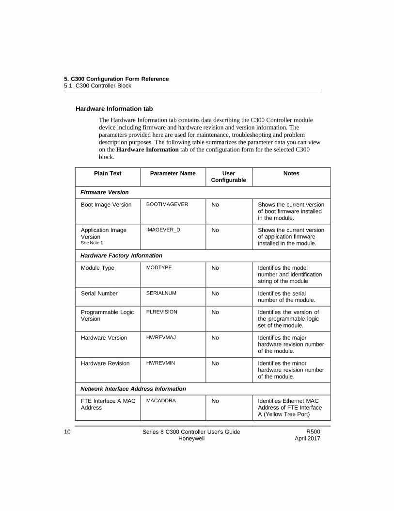
5. C300 Configuration Form Reference 5.1. C300 Controller Block
100
Series 8 C300 Controller User's Guide Honeywell
R500 April 2017
Hardware Information tab
The Hardware Information tab contains data describing the C300 Controller module
device including firmware and hardware revision and version information. The
parameters provided here are used for maintenance, troubleshooting and problem
description purposes. The following table summarizes the parameter data you can view
on the Hardware Information tab of the configuration form for the selected C300
block.
Plain Text Parameter Name User Configurable
Notes
Firmware Version
Boot Image Version BOOTIMAGEVER No Shows the current version of boot firmware installed in the module.
Application Image
Version See Note 1
IMAGEVER_D No Shows the current version of application firmware installed in the module.
Hardware Factory Information
Module Type MODTYPE No Identifies the model number and identification string of the module.
Serial Number SERIALNUM No Identifies the serial number of the module.
Programmable Logic Version
PLREVISION No Identifies the version of the programmable logic set of the module.
Hardware Version HWREVMAJ No Identifies the major hardware revision number of the module.
Hardware Revision HWREVMIN No Identifies the minor hardware revision number of the module.
Network Interface Address Information
FTE Interface A MAC Address
MACADDRA No Identifies Ethernet MAC Address of FTE Interface A (Yellow Tree Port)
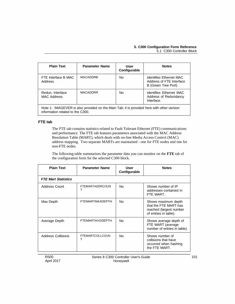
5. C300 Configuration Form Reference 5.1. C300 Controller Block
R500 April 2017
Series 8 C300 Controller User's Guide Honeywell
101
Plain Text Parameter Name User Configurable
Notes
FTE Interface B MAC Address
MACADDRB No Identifies Ethernet MAC Address of FTE Interface B (Green Tree Port)
Redun. Interface MAC Address
MACADDRR No Identifies Ethernet MAC Address of Redundancy Interface.
Note 1: IMAGEVER is also provided on the Main Tab; it is provided here with other version information related to the C300.
FTE tab
The FTE tab contains statistics related to Fault Tolerant Ethernet (FTE) communications
and performance. The FTE tab features parameters associated with the MAC Address
Resolution Table (MART), which deals with on-line Media Access Control (MAC)
address mapping. Two separate MARTs are maintained - one for FTE nodes and one for
non-FTE nodes.
The following table summarizes the parameter data you can monitor on the FTE tab of
the configuration form for the selected C300 block.
Plain Text Parameter Name User Configurable
Notes
FTE Mart Statistics
Address Count FTEMARTADDRCOUN T
No Shows number of IP addresses contained in FTE MART.
Max Depth FTEMARTMAXDEPTH No Shows maximum depth that the FTE MART has reached (largest number of entries in table).
Average Depth FTEMARTAVGDEPTH No Shows average depth of FTE MART (average number of entries in table).
Address Collisions FTEMARTCOLLCOUN T
No Shows number of collisions that have occurred when hashing the FTE MART.
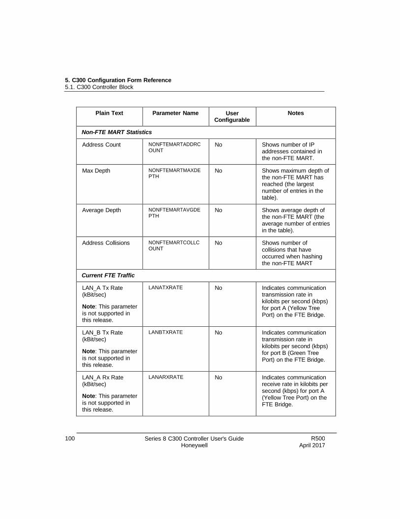
5. C300 Configuration Form Reference 5.1. C300 Controller Block
100 Series 8 C300 Controller User's Guide Honeywell
R500 April 2017
Plain Text Parameter Name User Configurable
Notes
Non-FTE MART Statistics
Address Count NONFTEMARTADDRC OUNT
No Shows number of IP addresses contained in the non-FTE MART.
Max Depth NONFTEMARTMAXDE PTH
No Shows maximum depth of the non-FTE MART has reached (the largest number of entries in the table).
Average Depth NONFTEMARTAVGDE PTH
No Shows average depth of the non-FTE MART (the average number of entries in the table).
Address Collisions NONFTEMARTCOLLC OUNT
No Shows number of collisions that have occurred when hashing the non-FTE MART
Current FTE Traffic
LAN_A Tx Rate (kBit/sec)
Note: This parameter is not supported in this release.
LANATXRATE No Indicates communication transmission rate in kilobits per second (kbps) for port A (Yellow Tree Port) on the FTE Bridge.
LAN_B Tx Rate (kBit/sec)
Note: This parameter is not supported in this release.
LANBTXRATE No Indicates communication transmission rate in kilobits per second (kbps) for port B (Green Tree Port) on the FTE Bridge.
LAN_A Rx Rate (kBit/sec)
Note: This parameter is not supported in this release.
LANARXRATE No Indicates communication receive rate in kilobits per second (kbps) for port A (Yellow Tree Port) on the FTE Bridge.

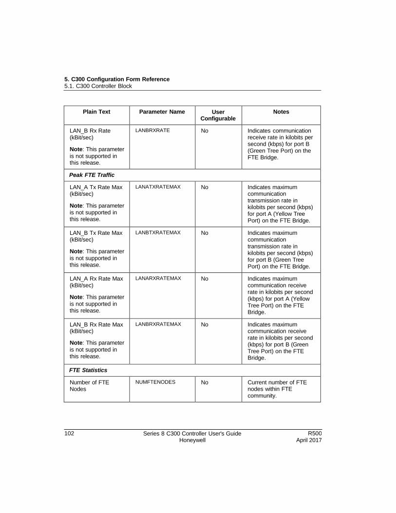
5. C300 Configuration Form Reference 5.1. C300 Controller Block
102 Series 8 C300 Controller User's Guide Honeywell
R500 April 2017
Plain Text Parameter Name User Configurable
Notes
LAN_B Rx Rate (kBit/sec)
Note: This parameter
is not supported in this release.
LANBRXRATE No Indicates communication receive rate in kilobits per second (kbps) for port B (Green Tree Port) on the FTE Bridge.
Peak FTE Traffic
LAN_A Tx Rate Max (kBit/sec)
Note: This parameter is not supported in this release.
LANATXRATEMAX No Indicates maximum communication transmission rate in kilobits per second (kbps) for port A (Yellow Tree Port) on the FTE Bridge.
LAN_B Tx Rate Max (kBit/sec)
Note: This parameter
is not supported in this release.
LANBTXRATEMAX No Indicates maximum communication transmission rate in kilobits per second (kbps) for port B (Green Tree Port) on the FTE Bridge.
LAN_A Rx Rate Max (kBit/sec)
Note: This parameter
is not supported in this release.
LANARXRATEMAX No Indicates maximum communication receive rate in kilobits per second (kbps) for port A (Yellow Tree Port) on the FTE Bridge.
LAN_B Rx Rate Max (kBit/sec)
Note: This parameter
is not supported in this release.
LANBRXRATEMAX No Indicates maximum communication receive rate in kilobits per second (kbps) for port B (Green Tree Port) on the FTE Bridge.
FTE Statistics
Number of FTE Nodes
NUMFTENODES No Current number of FTE nodes within FTE community.
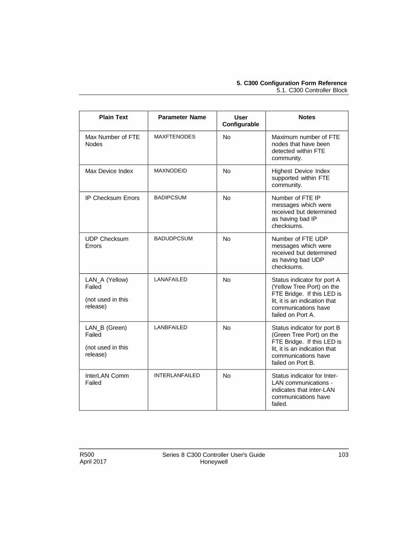
5. C300 Configuration Form Reference 5.1. C300 Controller Block
R500 April 2017
Series 8 C300 Controller User's Guide Honeywell
103
Plain Text Parameter Name User Configurable
Notes
Max Number of FTE Nodes
MAXFTENODES No Maximum number of FTE nodes that have been detected within FTE community.
Max Device Index MAXNODEID No Highest Device Index supported within FTE community.
IP Checksum Errors BADIPCSUM No Number of FTE IP messages which were received but determined as having bad IP checksums.
UDP Checksum Errors
BADUDPCSUM No Number of FTE UDP messages which were received but determined as having bad UDP checksums.
LAN_A (Yellow) Failed
(not used in this release)
LANAFAILED No Status indicator for port A (Yellow Tree Port) on the FTE Bridge. If this LED is lit, it is an indication that communications have failed on Port A.
LAN_B (Green) Failed
(not used in this release)
LANBFAILED No Status indicator for port B (Green Tree Port) on the FTE Bridge. If this LED is lit, it is an indication that communications have failed on Port B.
InterLAN Comm Failed
INTERLANFAILED No Status indicator for Inter- LAN communications - indicates that inter-LAN communications have failed.
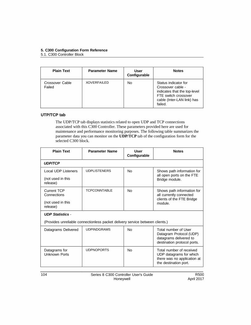
5. C300 Configuration Form Reference 5.1. C300 Controller Block
104 Series 8 C300 Controller User's Guide Honeywell
R500 April 2017
Plain Text Parameter Name User Configurable
Notes
Crossover Cable Failed
XOVERFAILED No Status indicator for Crossover cable - indicates that the top-level FTE switch crossover cable (Inter-LAN link) has failed.
UTP/TCP tab
The UDP/TCP tab displays statistics related to open UDP and TCP connections
associated with this C300 Controller. These parameters provided here are used for
maintenance and performance monitoring purposes. The following table summarizes the
parameter data you can monitor on the UDP/TCP tab of the configuration form for the
selected C300 block.
Plain Text Parameter Name User Configurable
Notes
UDP/TCP
Local UDP Listeners
(not used in this release)
UDPLISTENERS No Shows path information for all open ports on the FTE Bridge module.
Current TCP Connections
(not used in this release)
TCPCONNTABLE No Shows path information for all currently connected clients of the FTE Bridge module.
UDP Statistics -
(Provides unreliable connectionless packet delivery service between clients.)
Datagrams Delivered UDPINDGRAMS No Total number of User Datagram Protocol (UDP) datagrams delivered to destination protocol ports.
Datagrams for Unknown Ports
UDPNOPORTS No Total number of received UDP datagrams for which there was no application at the destination port.
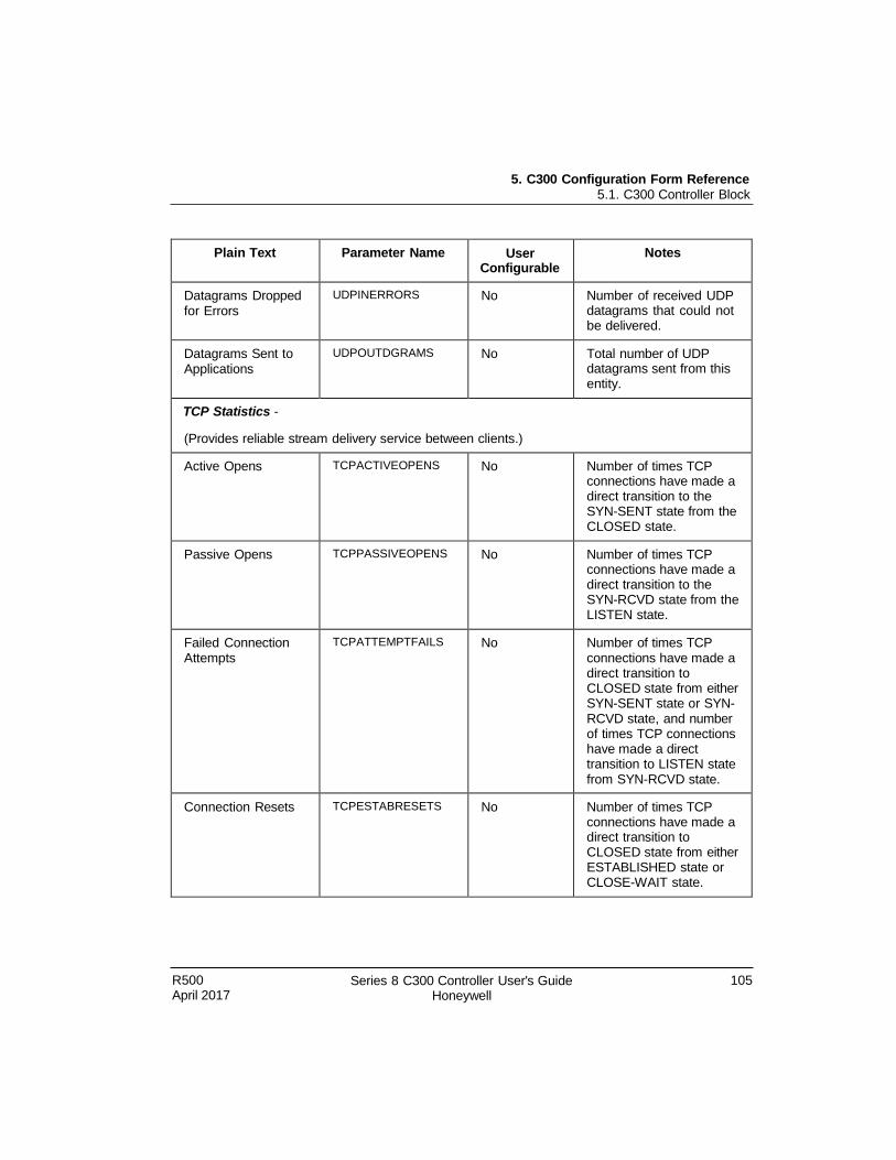
5. C300 Configuration Form Reference 5.1. C300 Controller Block
R500 April 2017
Series 8 C300 Controller User's Guide Honeywell
105
Plain Text Parameter Name User Configurable
Notes
Datagrams Dropped for Errors
UDPINERRORS No Number of received UDP datagrams that could not be delivered.
Datagrams Sent to Applications
UDPOUTDGRAMS No Total number of UDP datagrams sent from this entity.
TCP Statistics -
(Provides reliable stream delivery service between clients.)
Active Opens TCPACTIVEOPENS No Number of times TCP connections have made a direct transition to the SYN-SENT state from the CLOSED state.
Passive Opens TCPPASSIVEOPENS No Number of times TCP connections have made a direct transition to the SYN-RCVD state from the LISTEN state.
Failed Connection Attempts
TCPATTEMPTFAILS No Number of times TCP connections have made a direct transition to CLOSED state from either SYN-SENT state or SYN- RCVD state, and number of times TCP connections have made a direct transition to LISTEN state from SYN-RCVD state.
Connection Resets TCPESTABRESETS No Number of times TCP connections have made a direct transition to CLOSED state from either ESTABLISHED state or CLOSE-WAIT state.
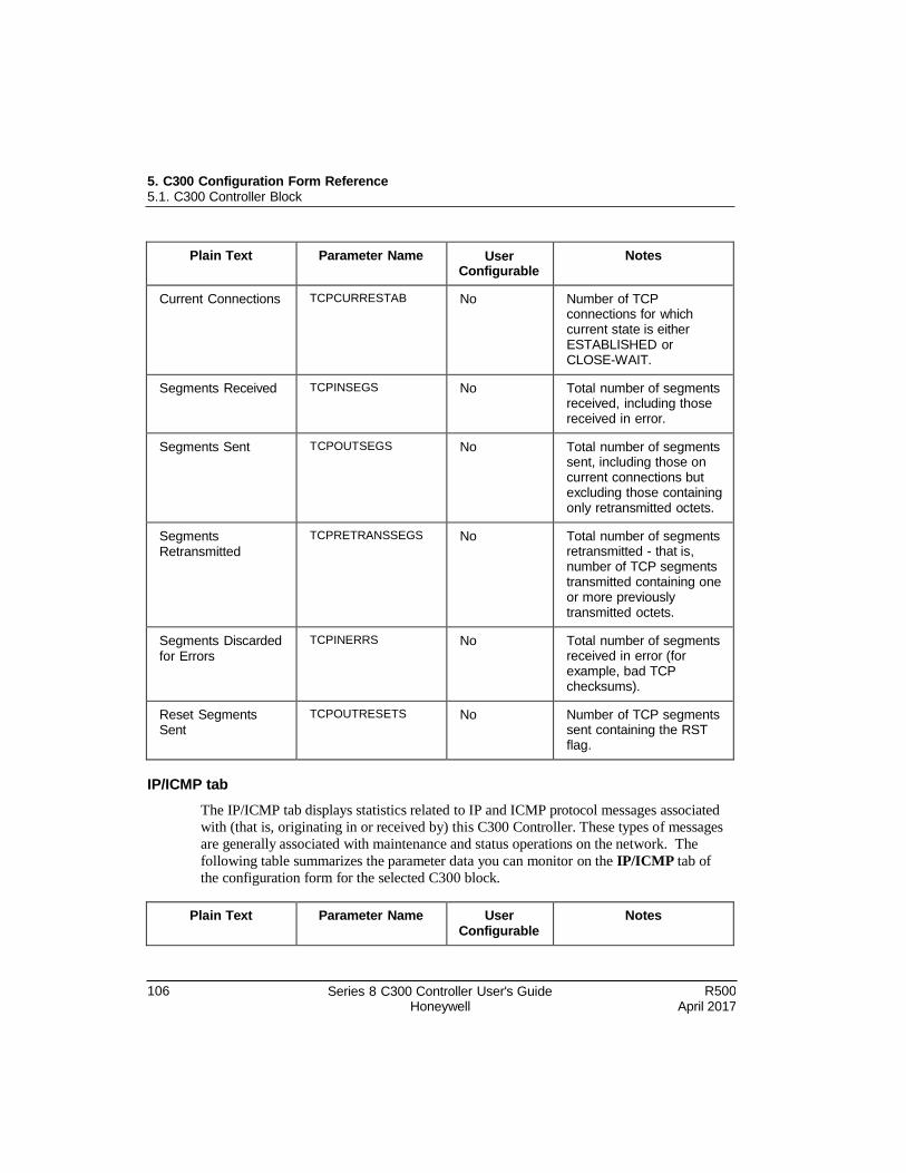
5. C300 Configuration Form Reference 5.1. C300 Controller Block
106 Series 8 C300 Controller User's Guide Honeywell
R500 April 2017
Plain Text Parameter Name User Configurable
Notes
Current Connections TCPCURRESTAB No Number of TCP connections for which current state is either ESTABLISHED or CLOSE-WAIT.
Segments Received TCPINSEGS No Total number of segments received, including those received in error.
Segments Sent TCPOUTSEGS No Total number of segments sent, including those on current connections but excluding those containing only retransmitted octets.
Segments Retransmitted
TCPRETRANSSEGS No Total number of segments retransmitted - that is, number of TCP segments transmitted containing one or more previously transmitted octets.
Segments Discarded for Errors
TCPINERRS No Total number of segments received in error (for example, bad TCP checksums).
Reset Segments Sent
TCPOUTRESETS No Number of TCP segments sent containing the RST flag.
IP/ICMP tab
The IP/ICMP tab displays statistics related to IP and ICMP protocol messages associated
with (that is, originating in or received by) this C300 Controller. These types of messages
are generally associated with maintenance and status operations on the network. The
following table summarizes the parameter data you can monitor on the IP/ICMP tab of
the configuration form for the selected C300 block.
Plain Text Parameter Name User Configurable
Notes
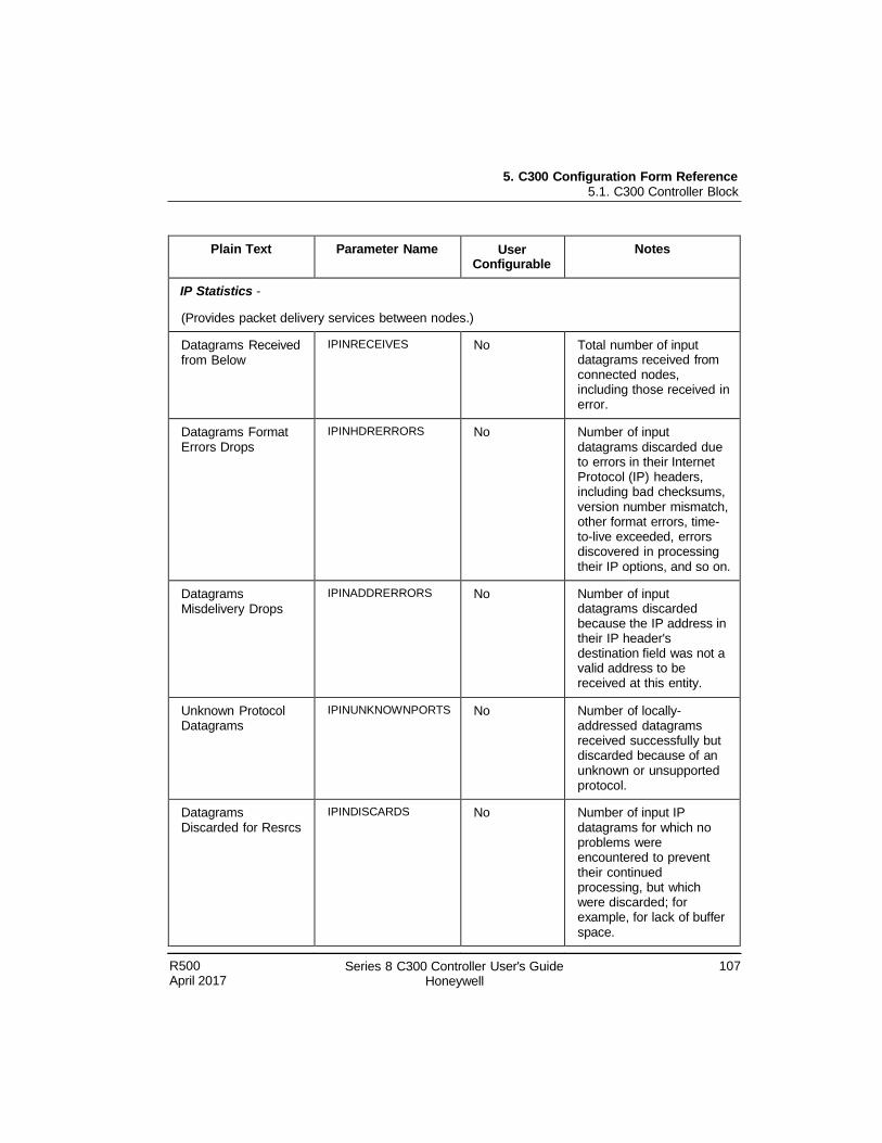
5. C300 Configuration Form Reference 5.1. C300 Controller Block
R500 April 2017
Series 8 C300 Controller User's Guide Honeywell
107
Plain Text Parameter Name User Configurable
Notes
IP Statistics -
(Provides packet delivery services between nodes.)
Datagrams Received from Below
IPINRECEIVES No Total number of input datagrams received from connected nodes, including those received in error.
Datagrams Format Errors Drops
IPINHDRERRORS No Number of input datagrams discarded due to errors in their Internet Protocol (IP) headers, including bad checksums, version number mismatch, other format errors, time- to-live exceeded, errors discovered in processing their IP options, and so on.
Datagrams Misdelivery Drops
IPINADDRERRORS No Number of input datagrams discarded because the IP address in their IP header's destination field was not a valid address to be received at this entity.
Unknown Protocol Datagrams
IPINUNKNOWNPORTS No Number of locally- addressed datagrams received successfully but discarded because of an unknown or unsupported protocol.
Datagrams Discarded for Resrcs
IPINDISCARDS No Number of input IP datagrams for which no problems were encountered to prevent their continued processing, but which were discarded; for example, for lack of buffer space.
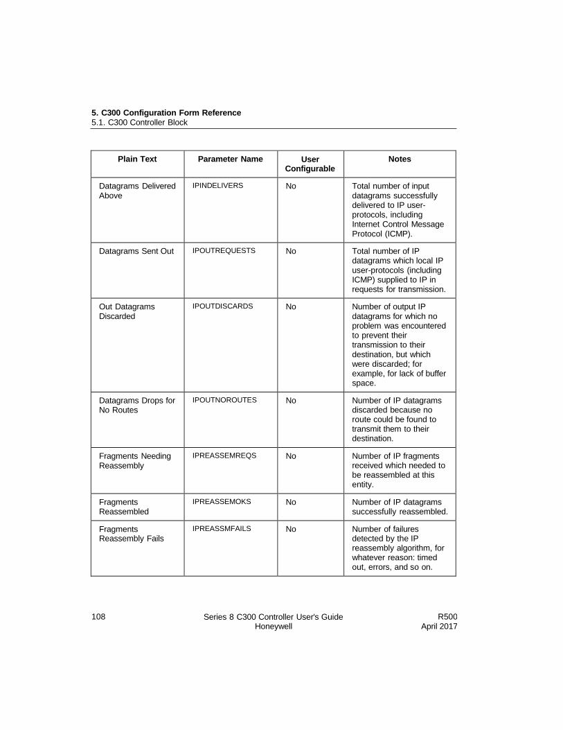
5. C300 Configuration Form Reference 5.1. C300 Controller Block
108 Series 8 C300 Controller User's Guide Honeywell
R500 April 2017
Plain Text Parameter Name User Configurable
Notes
Datagrams Delivered Above
IPINDELIVERS No Total number of input datagrams successfully delivered to IP user- protocols, including Internet Control Message Protocol (ICMP).
Datagrams Sent Out IPOUTREQUESTS No Total number of IP datagrams which local IP user-protocols (including ICMP) supplied to IP in requests for transmission.
Out Datagrams Discarded
IPOUTDISCARDS No Number of output IP datagrams for which no problem was encountered to prevent their transmission to their destination, but which were discarded; for example, for lack of buffer space.
Datagrams Drops for No Routes
IPOUTNOROUTES No Number of IP datagrams discarded because no route could be found to transmit them to their destination.
Fragments Needing Reassembly
IPREASSEMREQS No Number of IP fragments received which needed to be reassembled at this entity.
Fragments Reassembled
IPREASSEMOKS No Number of IP datagrams successfully reassembled.
Fragments Reassembly Fails
IPREASSMFAILS No Number of failures detected by the IP reassembly algorithm, for whatever reason: timed out, errors, and so on.
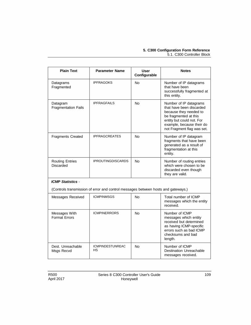
5. C300 Configuration Form Reference 5.1. C300 Controller Block
R500 April 2017
Series 8 C300 Controller User's Guide Honeywell
109
Plain Text Parameter Name User Configurable
Notes
Datagrams Fragmented
IPFRAGOKS No Number of IP datagrams that have been successfully fragmented at this entity.
Datagram Fragmentation Fails
IPFRAGFAILS No Number of IP datagrams that have been discarded because they needed to be fragmented at this entity but could not. For example, because their do not Fragment flag was set.
Fragments Created IPFRAGCREATES No Number of IP datagram fragments that have been generated as a result of fragmentation at this entity.
Routing Entries Discarded
IPROUTINGDISCARDS No Number of routing entries which were chosen to be discarded even though they are valid.
ICMP Statistics -
(Controls transmission of error and control messages between hosts and gateways.)
Messages Received ICMPINMSGS No Total number of ICMP messages which the entity received.
Messages With Format Errors
ICMPINERRORS No Number of ICMP messages which entity received but determined as having ICMP-specific errors such as bad ICMP checksums and bad length.
Dest. Unreachable Msgs Recvd
ICMPINDESTUNREAC HS
No Number of ICMP Destination Unreachable messages received.
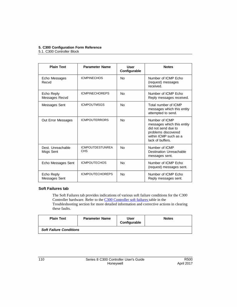
5. C300 Configuration Form Reference 5.1. C300 Controller Block
110 Series 8 C300 Controller User's Guide Honeywell
R500 April 2017
Plain Text Parameter Name User Configurable
Notes
Echo Messages Recvd
ICMPINECHOS No Number of ICMP Echo (request) messages received.
Echo Reply Messages Recvd
ICMPINECHOREPS No Number of ICMP Echo Reply messages received.
Messages Sent ICMPOUTMSGS No Total number of ICMP messages which this entity attempted to send.
Out Error Messages ICMPOUTERRORS No Number of ICMP messages which this entity did not send due to problems discovered within ICMP such as a lack of buffers.
Dest. Unreachable Msgs Sent
ICMPOUTDESTUNREA CHS
No Number of ICMP Destination Unreachable messages sent.
Echo Messages Sent ICMPOUTECHOS No Number of ICMP Echo (request) messages sent.
Echo Reply Messages Sent
ICMPOUTECHOREPS No Number of ICMP Echo Reply messages sent.
Soft Failures tab
The Soft Failures tab provides indications of various soft failure conditions for the C300
Controller hardware. Refer to the C300 Controller soft failures table in the
Troubleshooting section for more detailed information and corrective actions in clearing
these faults.
Plain Text Parameter Name User Configurable
Notes
Soft Failure Conditions
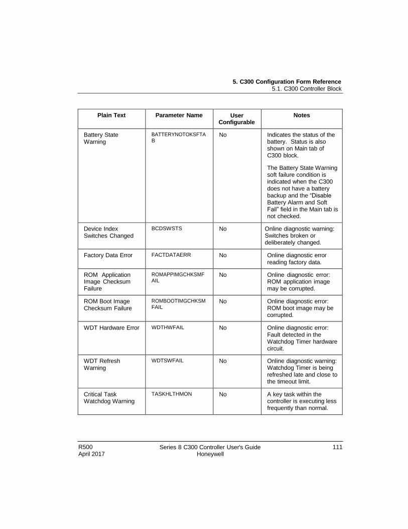
5. C300 Configuration Form Reference 5.1. C300 Controller Block
R500 April 2017
Series 8 C300 Controller User's Guide Honeywell
111
Plain Text Parameter Name User Configurable
Notes
Battery State Warning
BATTERYNOTOKSFTA B
No Indicates the status of the battery. Status is also shown on Main tab of C300 block.
The Battery State Warning soft failure condition is indicated when the C300 does not have a battery backup and the “Disable Battery Alarm and Soft Fail” field in the Main tab is not checked.
Device Index Switches Changed
BCDSWSTS No Online diagnostic warning: Switches broken or deliberately changed.
Factory Data Error FACTDATAERR No Online diagnostic error reading factory data.
ROM Application Image Checksum Failure
ROMAPPIMGCHKSMF AIL
No Online diagnostic error: ROM application image may be corrupted.
ROM Boot Image Checksum Failure
ROMBOOTIMGCHKSM FAIL
No Online diagnostic error: ROM boot image may be corrupted.
WDT Hardware Error WDTHWFAIL No Online diagnostic error: Fault detected in the Watchdog Timer hardware circuit.
WDT Refresh Warning
WDTSWFAIL No Online diagnostic warning: Watchdog Timer is being refreshed late and close to the timeout limit.
Critical Task Watchdog Warning
TASKHLTHMON No A key task within the controller is executing less frequently than normal.
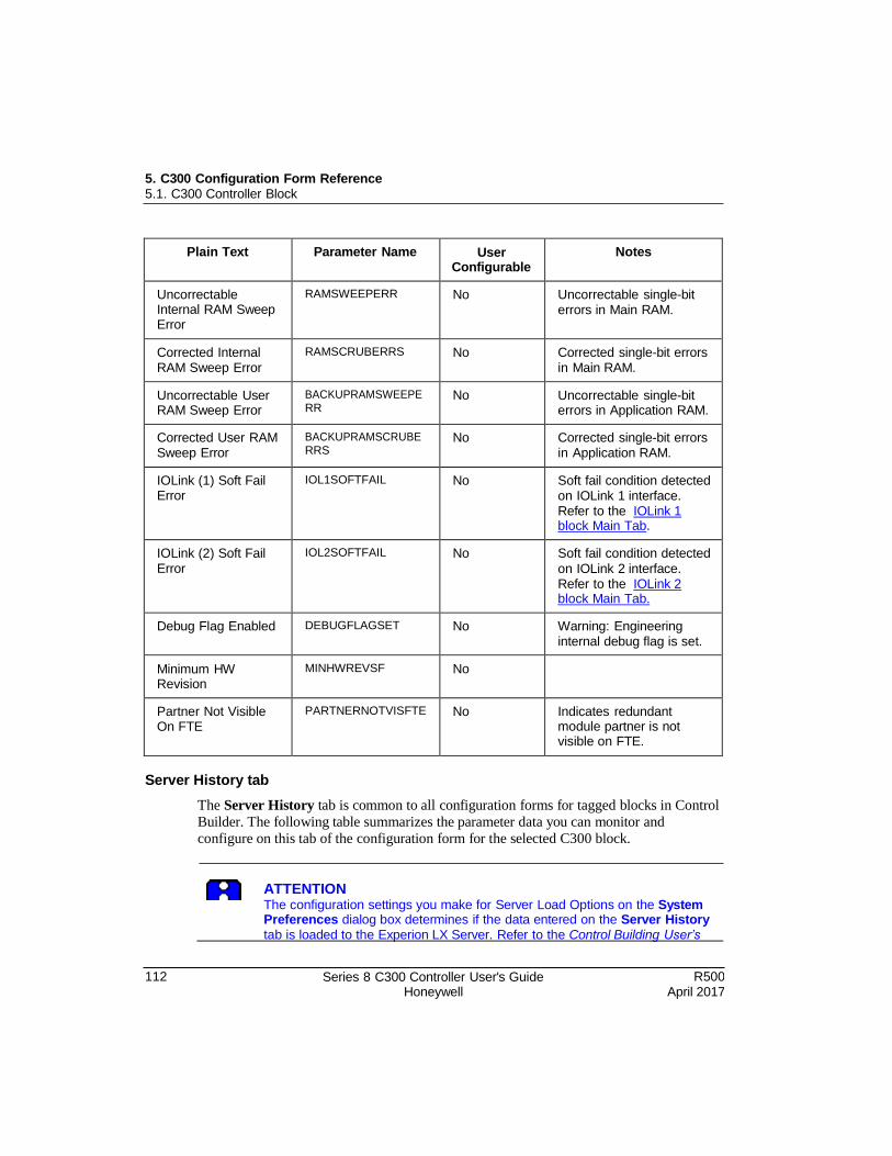
5. C300 Configuration Form Reference 5.1. C300 Controller Block
112 Series 8 C300 Controller User's Guide Honeywell
R500 April 2017
Plain Text Parameter Name User Configurable
Notes
Uncorrectable Internal RAM Sweep Error
RAMSWEEPERR No Uncorrectable single-bit errors in Main RAM.
Corrected Internal RAM Sweep Error
RAMSCRUBERRS No Corrected single-bit errors in Main RAM.
Uncorrectable User RAM Sweep Error
BACKUPRAMSWEEPE RR
No Uncorrectable single-bit errors in Application RAM.
Corrected User RAM Sweep Error
BACKUPRAMSCRUBE RRS
No Corrected single-bit errors in Application RAM.
IOLink (1) Soft Fail Error
IOL1SOFTFAIL No Soft fail condition detected on IOLink 1 interface. Refer to the IOLink 1 block Main Tab.
IOLink (2) Soft Fail Error
IOL2SOFTFAIL No Soft fail condition detected
on IOLink 2 interface. Refer to the IOLink 2 block Main Tab.
Debug Flag Enabled DEBUGFLAGSET No Warning: Engineering internal debug flag is set.
Minimum HW Revision
MINHWREVSF No
Partner Not Visible On FTE
PARTNERNOTVISFTE No Indicates redundant module partner is not visible on FTE.
Server History tab
The Server History tab is common to all configuration forms for tagged blocks in Control
Builder. The following table summarizes the parameter data you can monitor and
configure on this tab of the configuration form for the selected C300 block.
ATTENTION The configuration settings you make for Server Load Options on the System Preferences dialog box determines if the data entered on the Server History
tab is loaded to the Experion LX Server. Refer to the Control Building User’s
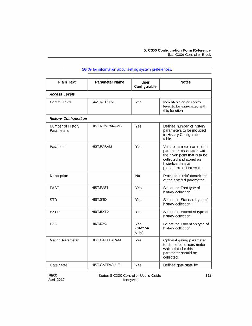
5. C300 Configuration Form Reference 5.1. C300 Controller Block
R500 April 2017
Series 8 C300 Controller User's Guide Honeywell
113
Guide for information about setting system preferences.
Plain Text Parameter Name User
Configurable
Notes
Access Levels
Control Level SCANCTRLLVL Yes Indicates Server control level to be associated with this function.
History Configuration
Number of History Parameters
HIST.NUMPARAMS Yes Defines number of history parameters to be included in History Configuration table.
Parameter HIST.PARAM Yes Valid parameter name for a parameter associated with the given point that is to be collected and stored as historical data at predetermined intervals.
Description No Provides a brief description of the entered parameter.
FAST HIST.FAST Yes Select the Fast type of history collection.
STD HIST.STD Yes Select the Standard type of history collection.
EXTD HIST.EXTD Yes Select the Extended type of history collection.
EXC HIST.EXC Yes (Station
only)
Select the Exception type of history collection.
Gating Parameter HIST.GATEPARAM Yes Optional gating parameter to define conditions under which data for this parameter should be collected.
Gate State HIST.GATEVALUE Yes Defines gate state for
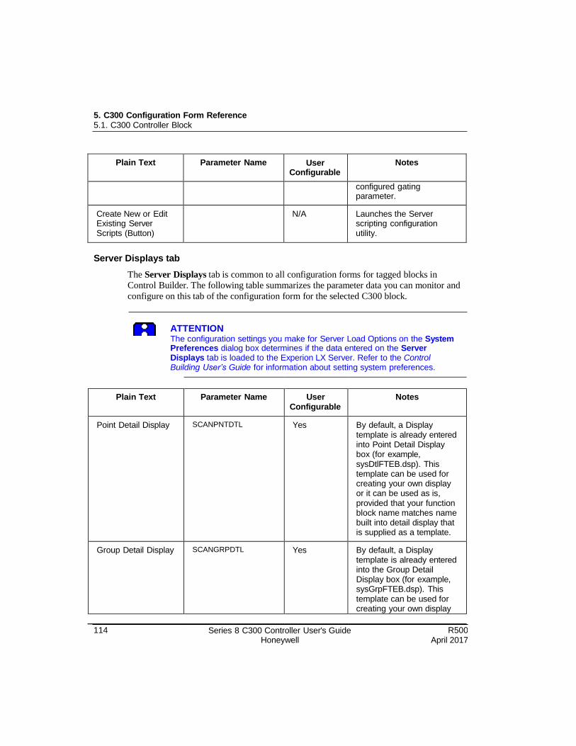
5. C300 Configuration Form Reference 5.1. C300 Controller Block
114 Series 8 C300 Controller User's Guide Honeywell
R500 April 2017
Plain Text Parameter Name User Configurable
Notes
configured gating parameter.
Create New or Edit Existing Server Scripts (Button)
N/A Launches the Server scripting configuration utility.
Server Displays tab
The Server Displays tab is common to all configuration forms for tagged blocks in
Control Builder. The following table summarizes the parameter data you can monitor and
configure on this tab of the configuration form for the selected C300 block.
ATTENTION The configuration settings you make for Server Load Options on the System Preferences dialog box determines if the data entered on the Server Displays tab is loaded to the Experion LX Server. Refer to the Control Building User’s Guide for information about setting system preferences.
Plain Text Parameter Name User
Configurable Notes
Point Detail Display SCANPNTDTL Yes By default, a Display template is already entered into Point Detail Display box (for example, sysDtlFTEB.dsp). This template can be used for creating your own display or it can be used as is, provided that your function block name matches name built into detail display that is supplied as a template.
Group Detail Display SCANGRPDTL Yes By default, a Display template is already entered into the Group Detail Display box (for example, sysGrpFTEB.dsp). This template can be used for creating your own display
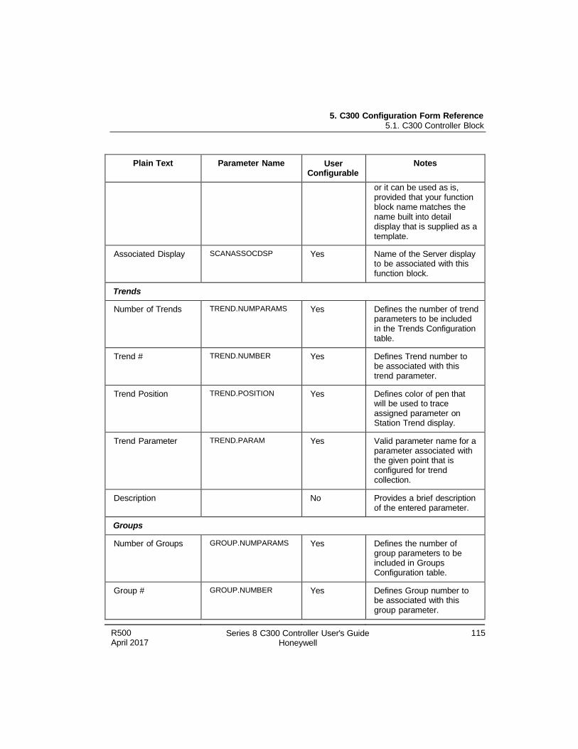
5. C300 Configuration Form Reference 5.1. C300 Controller Block
R500 April 2017
Series 8 C300 Controller User's Guide Honeywell
115
Plain Text Parameter Name User Configurable
Notes
or it can be used as is, provided that your function block name matches the name built into detail display that is supplied as a template.
Associated Display SCANASSOCDSP Yes Name of the Server display to be associated with this function block.
Trends
Number of Trends TREND.NUMPARAMS Yes Defines the number of trend parameters to be included in the Trends Configuration table.
Trend # TREND.NUMBER Yes Defines Trend number to be associated with this trend parameter.
Trend Position TREND.POSITION Yes Defines color of pen that will be used to trace assigned parameter on Station Trend display.
Trend Parameter TREND.PARAM Yes Valid parameter name for a parameter associated with the given point that is configured for trend collection.
Description No Provides a brief description of the entered parameter.
Groups
Number of Groups GROUP.NUMPARAMS Yes Defines the number of group parameters to be included in Groups Configuration table.
Group # GROUP.NUMBER Yes Defines Group number to be associated with this group parameter.
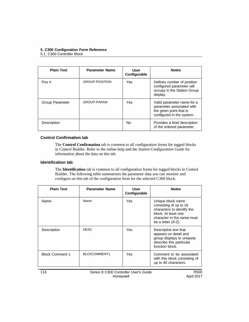
5. C300 Configuration Form Reference 5.1. C300 Controller Block
116 Series 8 C300 Controller User's Guide Honeywell
R500 April 2017
Plain Text Parameter Name User Configurable
Notes
Pos # GROUP.POSITION Yes Defines number of position configured parameter will occupy in the Station Group display.
Group Parameter GROUP.PARAM Yes Valid parameter name for a parameter associated with the given point that is configured in the system.
Description No Provides a brief description of the entered parameter.
Control Confirmation tab
The Control Confirmation tab is common to all configuration forms for tagged blocks in Control Builder. Refer to the online help and the Station Configuration Guide for
information about the data on this tab.
Identification tab
The Identification tab is common to all configuration forms for tagged blocks in Control
Builder. The following table summarizes the parameter data you can monitor and
configure on this tab of the configuration form for the selected C300 block.
Plain Text Parameter Name User Configurable
Notes
Name Name Yes Unique block name consisting of up to 16 characters to identify the block. At least one character in the name must be a letter (A-Z).
Description DESC Yes Descriptive text that appears on detail and group displays to uniquely describe this particular function block.
Block Comment 1 BLCKCOMMENT1 Yes Comment to be associated with this block consisting of up to 40 characters.
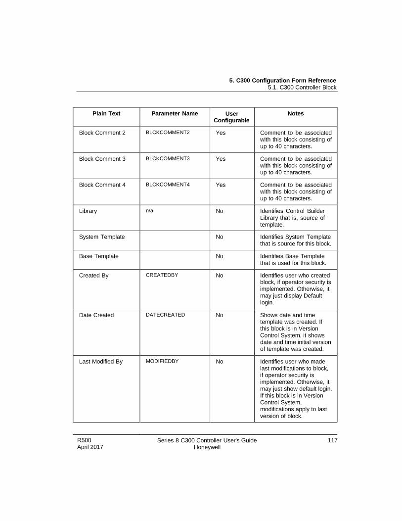
5. C300 Configuration Form Reference 5.1. C300 Controller Block
R500 April 2017
Series 8 C300 Controller User's Guide Honeywell
117
Plain Text Parameter Name User Configurable
Notes
Block Comment 2 BLCKCOMMENT2 Yes Comment to be associated with this block consisting of up to 40 characters.
Block Comment 3 BLCKCOMMENT3 Yes Comment to be associated with this block consisting of up to 40 characters.
Block Comment 4 BLCKCOMMENT4 Yes Comment to be associated with this block consisting of up to 40 characters.
Library n/a No Identifies Control Builder Library that is, source of template.
System Template No Identifies System Template that is source for this block.
Base Template No Identifies Base Template that is used for this block.
Created By CREATEDBY No Identifies user who created block, if operator security is implemented. Otherwise, it may just display Default login.
Date Created DATECREATED No Shows date and time template was created. If this block is in Version Control System, it shows date and time initial version of template was created.
Last Modified By MODIFIEDBY No Identifies user who made last modifications to block, if operator security is implemented. Otherwise, it may just show default login. If this block is in Version Control System, modifications apply to last version of block.
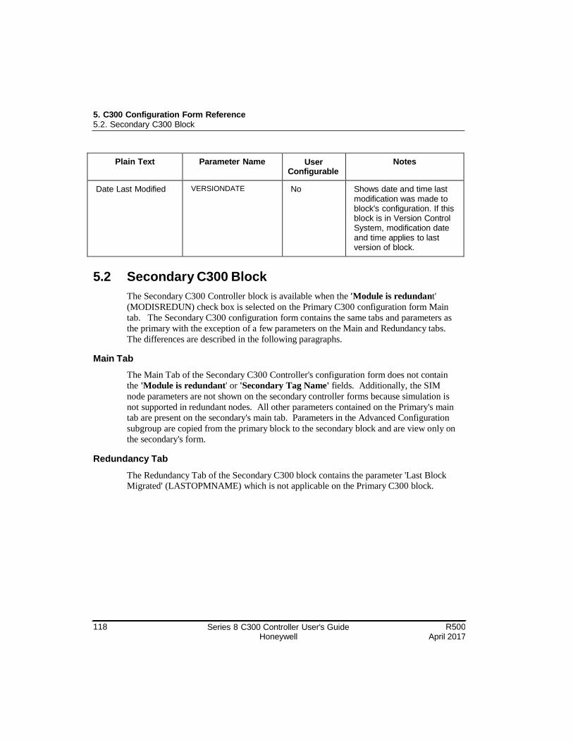
118 Series 8 C300 Controller User's Guide Honeywell
R500 April 2017
5. C300 Configuration Form Reference 5.2. Secondary C300 Block
Plain Text Parameter Name User Configurable
Notes
Date Last Modified VERSIONDATE No Shows date and time last modification was made to block's configuration. If this block is in Version Control System, modification date and time applies to last version of block.
5.2 Secondary C300 Block
The Secondary C300 Controller block is available when the 'Module is redundant'
(MODISREDUN) check box is selected on the Primary C300 configuration form Main
tab. The Secondary C300 configuration form contains the same tabs and parameters as
the primary with the exception of a few parameters on the Main and Redundancy tabs.
The differences are described in the following paragraphs.
Main Tab
The Main Tab of the Secondary C300 Controller's configuration form does not contain
the 'Module is redundant' or 'Secondary Tag Name' fields. Additionally, the SIM
node parameters are not shown on the secondary controller forms because simulation is
not supported in redundant nodes. All other parameters contained on the Primary's main
tab are present on the secondary's main tab. Parameters in the Advanced Configuration
subgroup are copied from the primary block to the secondary block and are view only on
the secondary's form.
Redundancy Tab
The Redundancy Tab of the Secondary C300 block contains the parameter 'Last Block Migrated' (LASTOPMNAME) which is not applicable on the Primary C300 block.
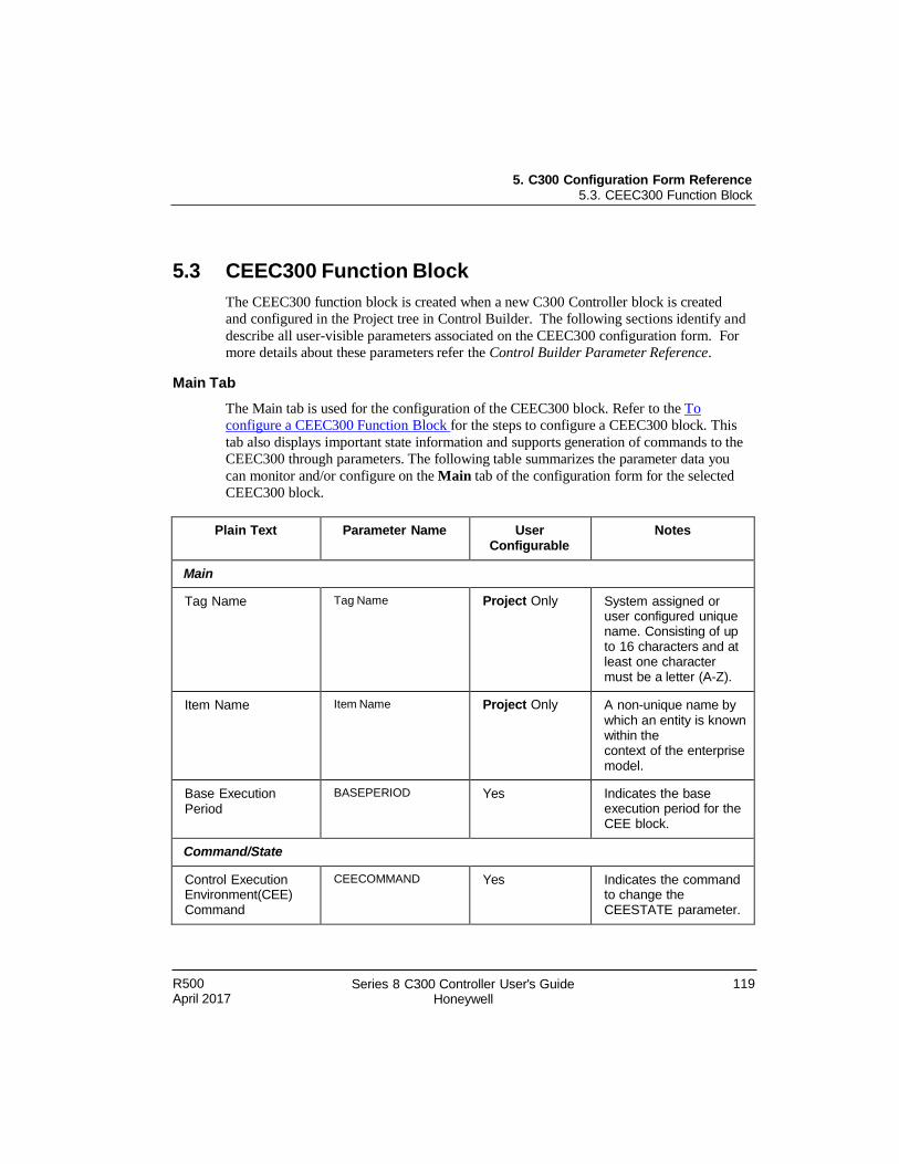
R500 April 2017
Series 8 C300 Controller User's Guide Honeywell
119
5. C300 Configuration Form Reference 5.3. CEEC300 Function Block
5.3 CEEC300 Function Block
The CEEC300 function block is created when a new C300 Controller block is created
and configured in the Project tree in Control Builder. The following sections identify and
describe all user-visible parameters associated on the CEEC300 configuration form. For
more details about these parameters refer the Control Builder Parameter Reference.
Main Tab
The Main tab is used for the configuration of the CEEC300 block. Refer to the To
configure a CEEC300 Function Block for the steps to configure a CEEC300 block. This
tab also displays important state information and supports generation of commands to the
CEEC300 through parameters. The following table summarizes the parameter data you
can monitor and/or configure on the Main tab of the configuration form for the selected
CEEC300 block.
Plain Text Parameter Name User Configurable
Notes
Main
Tag Name Tag Name Project Only System assigned or user configured unique name. Consisting of up to 16 characters and at least one character must be a letter (A-Z).
Item Name Item Name Project Only A non-unique name by which an entity is known within the context of the enterprise model.
Base Execution Period
BASEPERIOD Yes Indicates the base execution period for the CEE block.
Command/State
Control Execution Environment(CEE) Command
CEECOMMAND Yes Indicates the command to change the CEESTATE parameter.
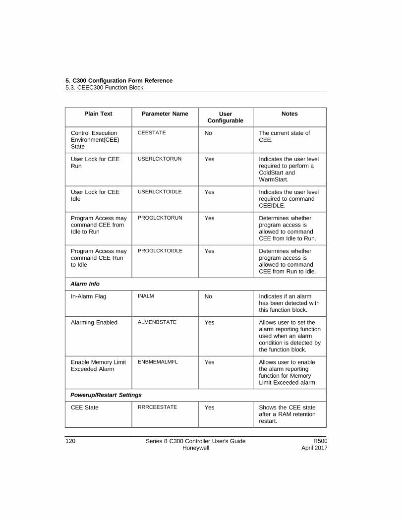
5. C300 Configuration Form Reference 5.3. CEEC300 Function Block
120 Series 8 C300 Controller User's Guide Honeywell
R500 April 2017
Plain Text Parameter Name User Configurable
Notes
Control Execution Environment(CEE) State
CEESTATE No The current state of CEE.
User Lock for CEE Run
USERLCKTORUN Yes Indicates the user level required to perform a ColdStart and WarmStart.
User Lock for CEE Idle
USERLCKTOIDLE Yes Indicates the user level required to command CEEIDLE.
Program Access may command CEE from Idle to Run
PROGLCKTORUN Yes Determines whether program access is allowed to command CEE from Idle to Run.
Program Access may command CEE Run to Idle
PROGLCKTOIDLE Yes Determines whether program access is allowed to command CEE from Run to Idle.
Alarm Info
In-Alarm Flag INALM No Indicates if an alarm has been detected with this function block.
Alarming Enabled ALMENBSTATE Yes Allows user to set the alarm reporting function used when an alarm condition is detected by the function block.
Enable Memory Limit Exceeded Alarm
ENBMEMALMFL Yes Allows user to enable the alarm reporting function for Memory Limit Exceeded alarm.
Powerup/Restart Settings
CEE State RRRCEESTATE Yes Shows the CEE state after a RAM retention restart.
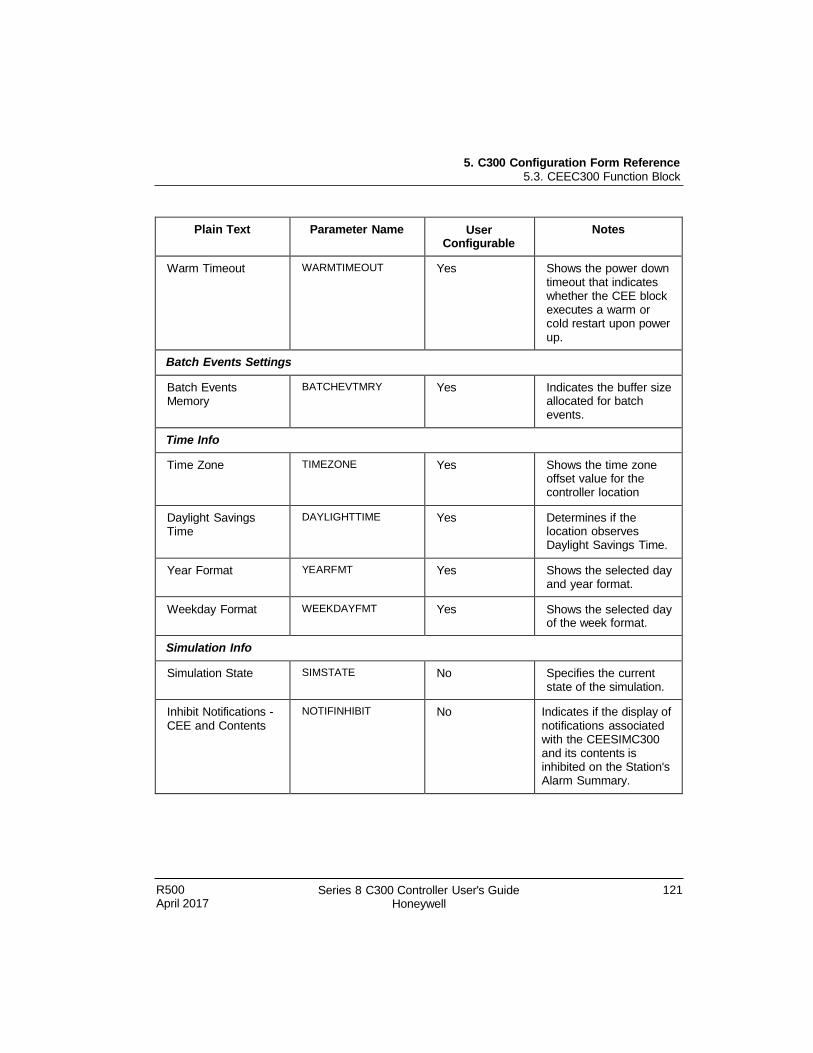
5. C300 Configuration Form Reference 5.3. CEEC300 Function Block
R500 April 2017
Series 8 C300 Controller User's Guide Honeywell
121
Plain Text Parameter Name User Configurable
Notes
Warm Timeout WARMTIMEOUT Yes Shows the power down timeout that indicates whether the CEE block executes a warm or cold restart upon power up.
Batch Events Settings
Batch Events Memory
BATCHEVTMRY Yes Indicates the buffer size allocated for batch events.
Time Info
Time Zone TIMEZONE Yes Shows the time zone offset value for the controller location
Daylight Savings Time
DAYLIGHTTIME Yes Determines if the location observes Daylight Savings Time.
Year Format YEARFMT Yes Shows the selected day and year format.
Weekday Format WEEKDAYFMT Yes Shows the selected day of the week format.
Simulation Info
Simulation State SIMSTATE No Specifies the current state of the simulation.
Inhibit Notifications - CEE and Contents
NOTIFINHIBIT No Indicates if the display of notifications associated with the CEESIMC300 and its contents is inhibited on the Station's Alarm Summary.
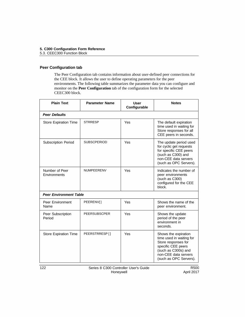
5. C300 Configuration Form Reference 5.3. CEEC300 Function Block
122 Series 8 C300 Controller User's Guide Honeywell
R500 April 2017
Peer Configuration tab
The Peer Configuration tab contains information about user-defined peer connections for
the CEE block. It allows the user to define operating parameters for the peer
environments. The following table summarizes the parameter data you can configure and
monitor on the Peer Configuration tab of the configuration form for the selected
CEEC300 block.
Plain Text Parameter Name User Configurable
Notes
Peer Defaults
Store Expiration Time STRRESP Yes The default expiration time used in waiting for Store responses for all CEE peers in seconds.
Subscription Period SUBSCPERIOD Yes The update period used for cyclic get requests for specific CEE peers (such as C300) and non-CEE data servers (such as OPC Servers).
Number of Peer Environments
NUMPEERENV Yes Indicates the number of peer environments (such as C300) configured for the CEE block.
Peer Environment Table
Peer Environment Name
PEERENV[ ] Yes Shows the name of the peer environment.
Peer Subscription Period
PEERSUBSCPER Yes Shows the update period of the peer environment in seconds.
Store Expiration Time PEERSTRRESP [ ] Yes Shows the expiration time used in waiting for Store responses for specific CEE peers (such as C300s) and non-CEE data servers (such as OPC Servers).
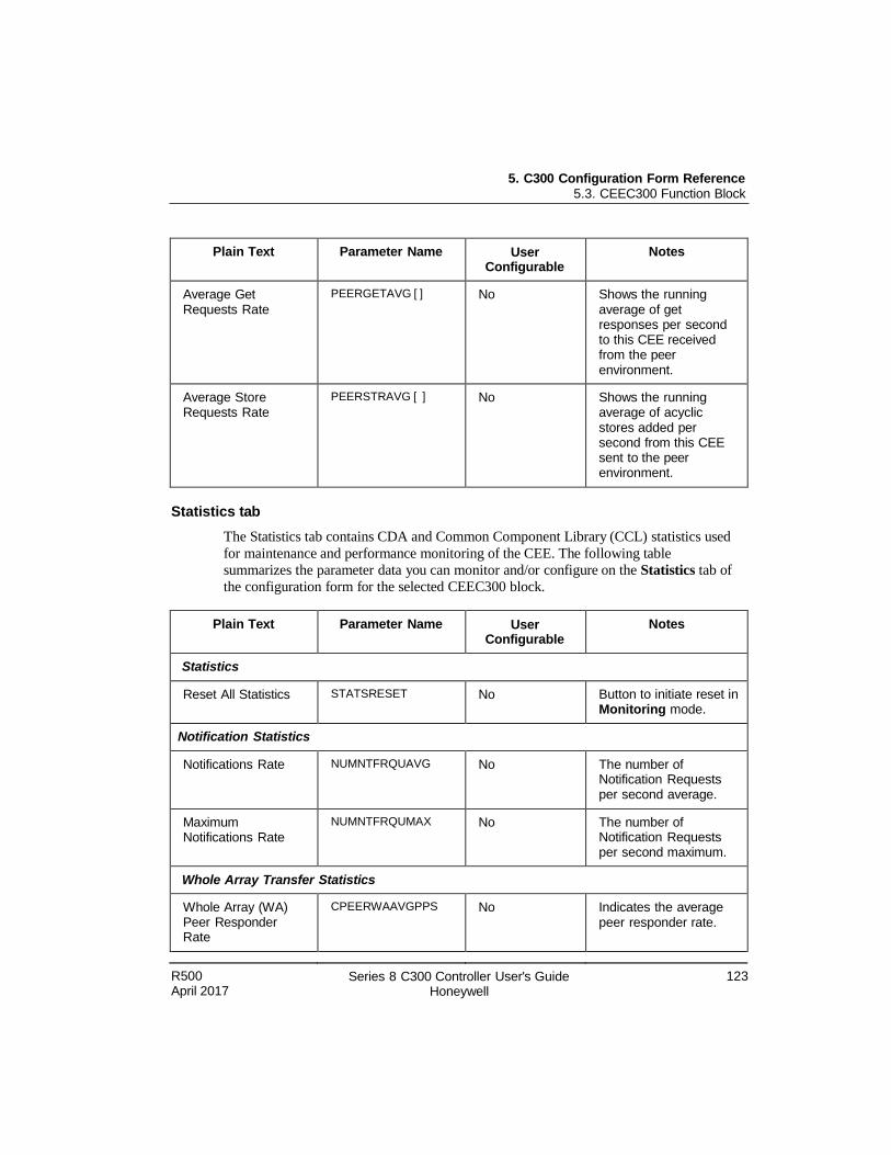
5. C300 Configuration Form Reference 5.3. CEEC300 Function Block
R500 April 2017
Series 8 C300 Controller User's Guide Honeywell
123
Plain Text Parameter Name User Configurable
Notes
Average Get Requests Rate
PEERGETAVG [ ] No Shows the running average of get responses per second to this CEE received from the peer environment.
Average Store Requests Rate
PEERSTRAVG [ ] No Shows the running average of acyclic stores added per second from this CEE sent to the peer environment.
Statistics tab
The Statistics tab contains CDA and Common Component Library (CCL) statistics used
for maintenance and performance monitoring of the CEE. The following table
summarizes the parameter data you can monitor and/or configure on the Statistics tab of
the configuration form for the selected CEEC300 block.
Plain Text Parameter Name User Configurable
Notes
Statistics
Reset All Statistics STATSRESET No Button to initiate reset in Monitoring mode.
Notification Statistics
Notifications Rate NUMNTFRQUAVG No The number of Notification Requests per second average.
Maximum Notifications Rate
NUMNTFRQUMAX No The number of Notification Requests per second maximum.
Whole Array Transfer Statistics
Whole Array (WA) Peer Responder Rate
CPEERWAAVGPPS No Indicates the average peer responder rate.
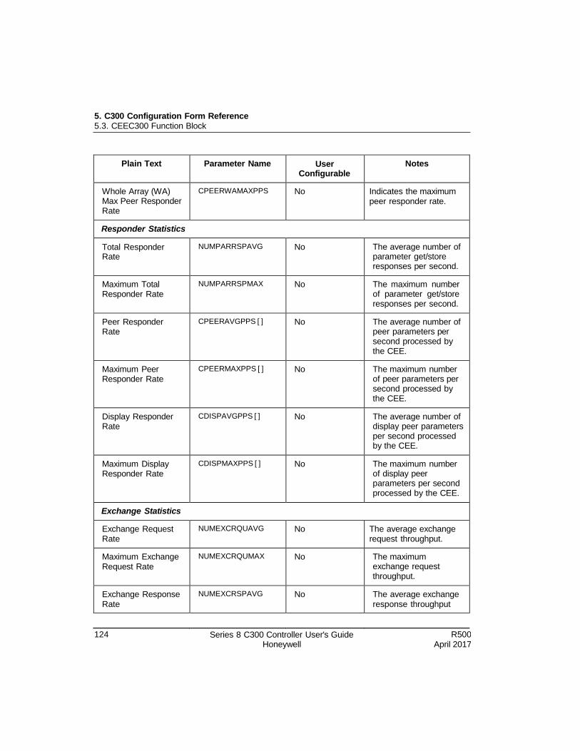
5. C300 Configuration Form Reference 5.3. CEEC300 Function Block
124 Series 8 C300 Controller User's Guide Honeywell
R500 April 2017
Plain Text Parameter Name User Configurable
Notes
Whole Array (WA) Max Peer Responder Rate
CPEERWAMAXPPS No Indicates the maximum peer responder rate.
Responder Statistics
Total Responder Rate
NUMPARRSPAVG No The average number of parameter get/store responses per second.
Maximum Total Responder Rate
NUMPARRSPMAX No The maximum number of parameter get/store responses per second.
Peer Responder Rate
CPEERAVGPPS [ ] No The average number of peer parameters per second processed by the CEE.
Maximum Peer Responder Rate
CPEERMAXPPS [ ] No The maximum number of peer parameters per second processed by the CEE.
Display Responder Rate
CDISPAVGPPS [ ] No The average number of display peer parameters per second processed by the CEE.
Maximum Display Responder Rate
CDISPMAXPPS [ ] No The maximum number of display peer parameters per second processed by the CEE.
Exchange Statistics
Exchange Request Rate
NUMEXCRQUAVG No The average exchange request throughput.
Maximum Exchange Request Rate
NUMEXCRQUMAX No The maximum exchange request throughput.
Exchange Response Rate
NUMEXCRSPAVG No The average exchange response throughput
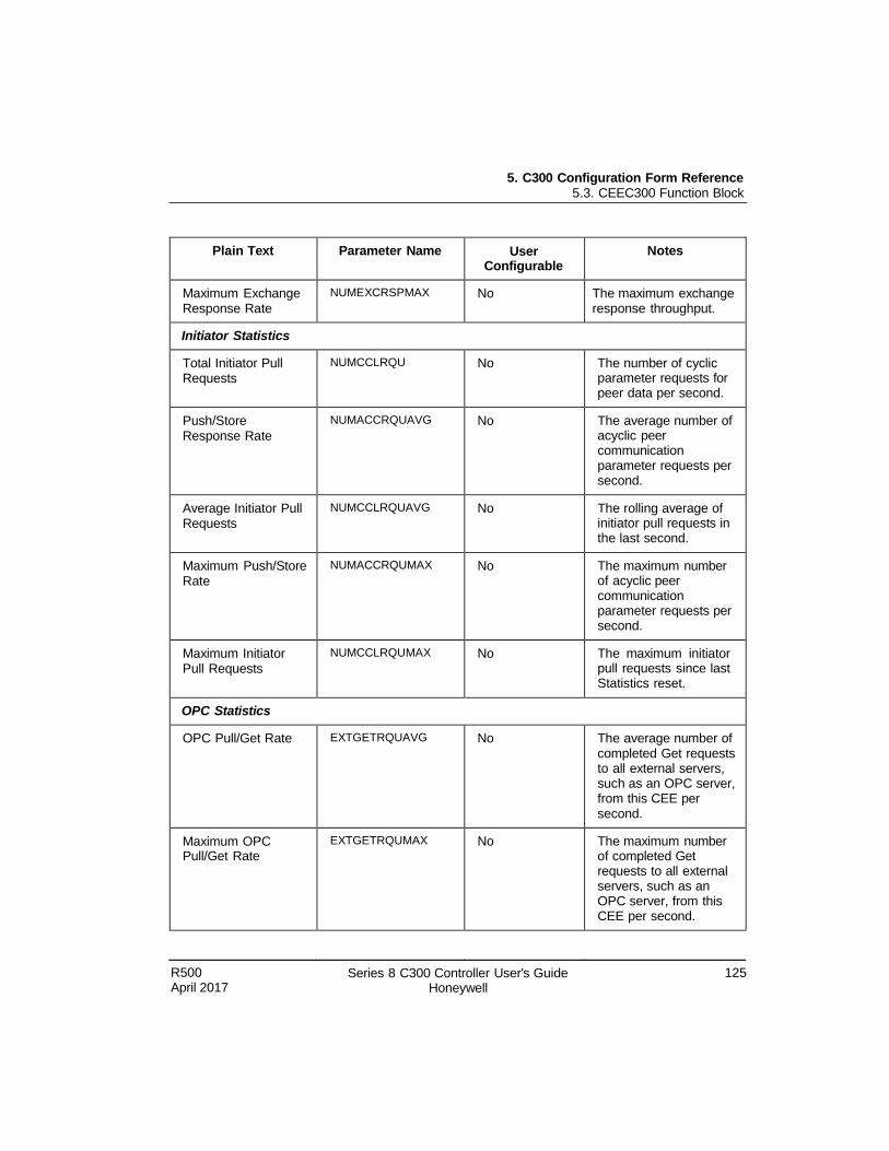
5. C300 Configuration Form Reference 5.3. CEEC300 Function Block
R500 April 2017
Series 8 C300 Controller User's Guide Honeywell
125
Plain Text Parameter Name User Configurable
Notes
Maximum Exchange Response Rate
NUMEXCRSPMAX No The maximum exchange response throughput.
Initiator Statistics
Total Initiator Pull Requests
NUMCCLRQU No The number of cyclic parameter requests for peer data per second.
Push/Store Response Rate
NUMACCRQUAVG No The average number of acyclic peer communication parameter requests per second.
Average Initiator Pull Requests
NUMCCLRQUAVG No The rolling average of initiator pull requests in the last second.
Maximum Push/Store Rate
NUMACCRQUMAX No The maximum number of acyclic peer communication parameter requests per second.
Maximum Initiator Pull Requests
NUMCCLRQUMAX No The maximum initiator pull requests since last Statistics reset.
OPC Statistics
OPC Pull/Get Rate EXTGETRQUAVG No The average number of completed Get requests to all external servers, such as an OPC server, from this CEE per second.
Maximum OPC Pull/Get Rate
EXTGETRQUMAX No The maximum number of completed Get requests to all external servers, such as an OPC server, from this CEE per second.
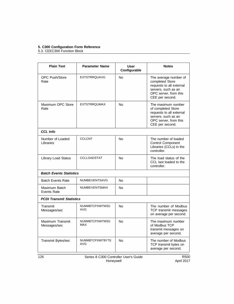
5. C300 Configuration Form Reference 5.3. CEEC300 Function Block
126 Series 8 C300 Controller User's Guide Honeywell
R500 April 2017
Plain Text Parameter Name User Configurable
Notes
OPC Push/Store Rate
EXTSTRRQUAVG No The average number of completed Store requests to all external servers, such as an OPC server, from this CEE per second.
Maximum OPC Store Rate
EXTSTRRQUMAX No The maximum number of completed Store requests to all external servers, such as an OPC server, from this CEE per second.
CCL Info
Number of Loaded Libraries
CCLCNT No The number of loaded Control Component Libraries (CCLs) in the controller.
Library Load Status CCLLOADSTAT No The load status of the CCL last loaded to the controller.
Batch Events Statistics
Batch Events Rate NUMBEVENTSAVG No
Maximum Batch Events Rate
NUMBEVENTSMAX No
PCDI Transmit Statistics
Transmit Messages/sec
NUMMBTCPXMITMSG AVG
No The number of Modbus TCP transmit messages on average per second.
Maximum Transmit Messages/sec
NUMMBTCPXMITMSG MAX
No The maximum number of Modbus TCP transmit messages on average per second.
Transmit Bytes/sec NUMMBTCPXMITBYTE AVG
No The number of Modbus TCP transmit bytes on average per second.
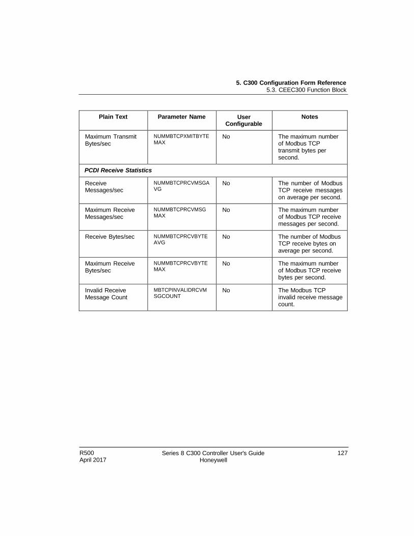
5. C300 Configuration Form Reference 5.3. CEEC300 Function Block
R500 April 2017
Series 8 C300 Controller User's Guide Honeywell
127
Plain Text Parameter Name User Configurable
Notes
Maximum Transmit Bytes/sec
NUMMBTCPXMITBYTE MAX
No The maximum number of Modbus TCP transmit bytes per second.
PCDI Receive Statistics
Receive Messages/sec
NUMMBTCPRCVMSGA VG
No The number of Modbus TCP receive messages on average per second.
Maximum Receive Messages/sec
NUMMBTCPRCVMSG MAX
No The maximum number of Modbus TCP receive messages per second.
Receive Bytes/sec NUMMBTCPRCVBYTE AVG
No The number of Modbus TCP receive bytes on average per second.
Maximum Receive Bytes/sec
NUMMBTCPRCVBYTE MAX
No The maximum number of Modbus TCP receive bytes per second.
Invalid Receive Message Count
MBTCPINVALIDRCVM SGCOUNT
No The Modbus TCP invalid receive message count.
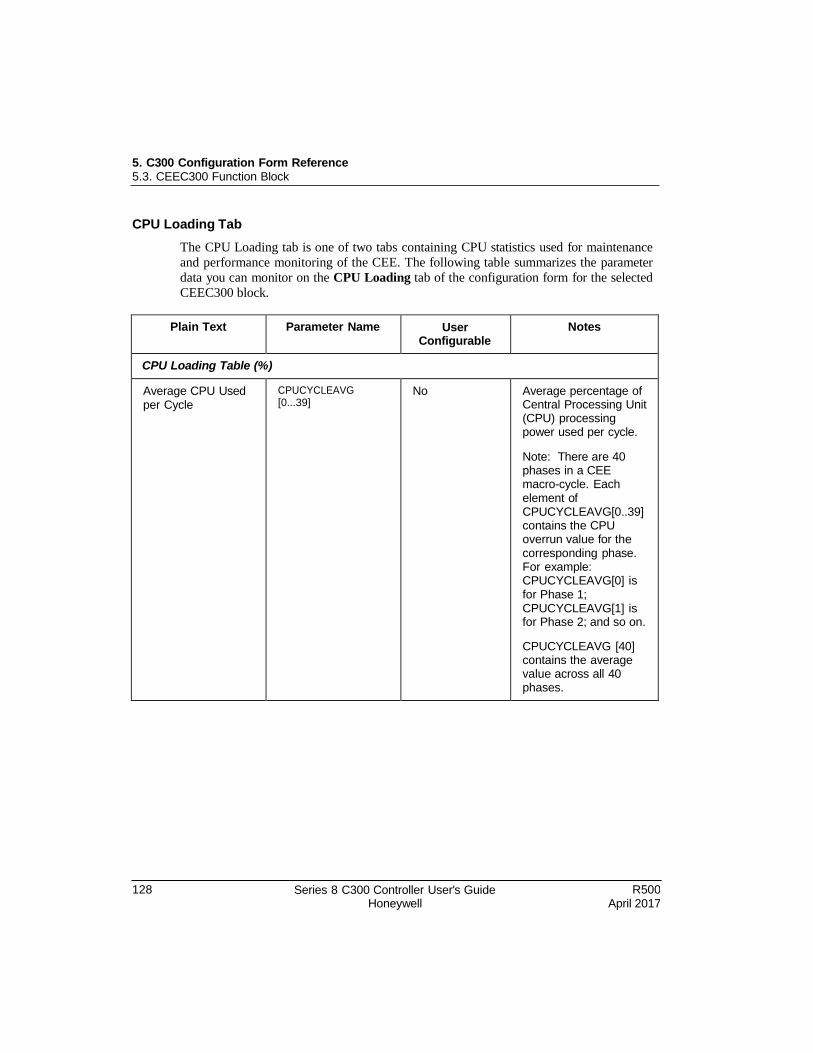
5. C300 Configuration Form Reference 5.3. CEEC300 Function Block
128 Series 8 C300 Controller User's Guide Honeywell
R500 April 2017
CPU Loading Tab
The CPU Loading tab is one of two tabs containing CPU statistics used for maintenance
and performance monitoring of the CEE. The following table summarizes the parameter
data you can monitor on the CPU Loading tab of the configuration form for the selected
CEEC300 block.
Plain Text Parameter Name User Configurable
Notes
CPU Loading Table (%)
Average CPU Used per Cycle
CPUCYCLEAVG [0...39]
No Average percentage of Central Processing Unit (CPU) processing power used per cycle.
Note: There are 40 phases in a CEE macro-cycle. Each element of CPUCYCLEAVG[0..39] contains the CPU overrun value for the corresponding phase. For example: CPUCYCLEAVG[0] is for Phase 1; CPUCYCLEAVG[1] is for Phase 2; and so on.
CPUCYCLEAVG [40] contains the average value across all 40 phases.
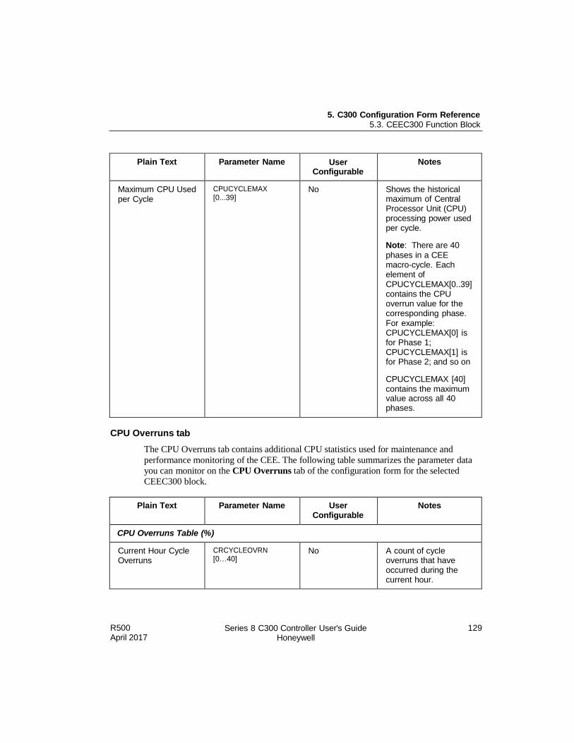
5. C300 Configuration Form Reference 5.3. CEEC300 Function Block
R500 April 2017
Series 8 C300 Controller User's Guide Honeywell
129
Plain Text Parameter Name User Configurable
Notes
Maximum CPU Used per Cycle
CPUCYCLEMAX [0...39]
No Shows the historical maximum of Central Processor Unit (CPU) processing power used per cycle.
Note: There are 40
phases in a CEE macro-cycle. Each element of CPUCYCLEMAX[0..39] contains the CPU overrun value for the corresponding phase. For example: CPUCYCLEMAX[0] is for Phase 1; CPUCYCLEMAX[1] is for Phase 2; and so on
CPUCYCLEMAX [40] contains the maximum value across all 40 phases.
CPU Overruns tab
The CPU Overruns tab contains additional CPU statistics used for maintenance and
performance monitoring of the CEE. The following table summarizes the parameter data
you can monitor on the CPU Overruns tab of the configuration form for the selected
CEEC300 block.
Plain Text Parameter Name User Configurable
Notes
CPU Overruns Table (%)
Current Hour Cycle Overruns
CRCYCLEOVRN [0…40]
No A count of cycle overruns that have occurred during the current hour.
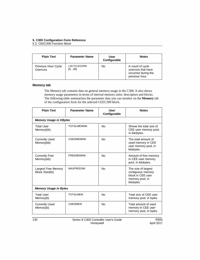
5. C300 Configuration Form Reference 5.3. CEEC300 Function Block
130 Series 8 C300 Controller User's Guide Honeywell
R500 April 2017
Plain Text Parameter Name User Configurable
Notes
Previous Hour Cycle Overruns
LSCYCLEOVRN [0…40]
No A count of cycle overruns that have occurred during the previous hour.
Memory tab
The Memory tab contains data on general memory usage in the C300. It also shows
memory usage parameters in terms of internal memory units: descriptors and blocks.
The following table summarizes the parameter data you can monitor on the Memory tab
of the configuration form for the selected CEEC300 block.
Plain Text Parameter Name User Configurable
Notes
Memory Usage in KBytes
Total User Memory(kb)
TOTALMEMINK No Shows the total size of CEE user memory pool, in kilobytes.
Currently Used Memory(kb)
USEDMEMINK No The total amount of used memory in CEE user memory pool, in kilobytes.
Currently Free Memory(kb)
FREEMEMINK No Amount of free memory in CEE user memory pool, in kilobytes.
Largest Free Memory Block Size(kb)
MAXFREEINK No The size of largest contiguous memory block in CEE user memory pool, in kilobytes.
Memory Usage in Bytes
Total User Memory(b)
TOTALMEM No Total size of CEE user memory pool, in bytes.
Currently Used Memory(b)
USEDMEM No Total amount of used memory in CEE user memory pool, in bytes.
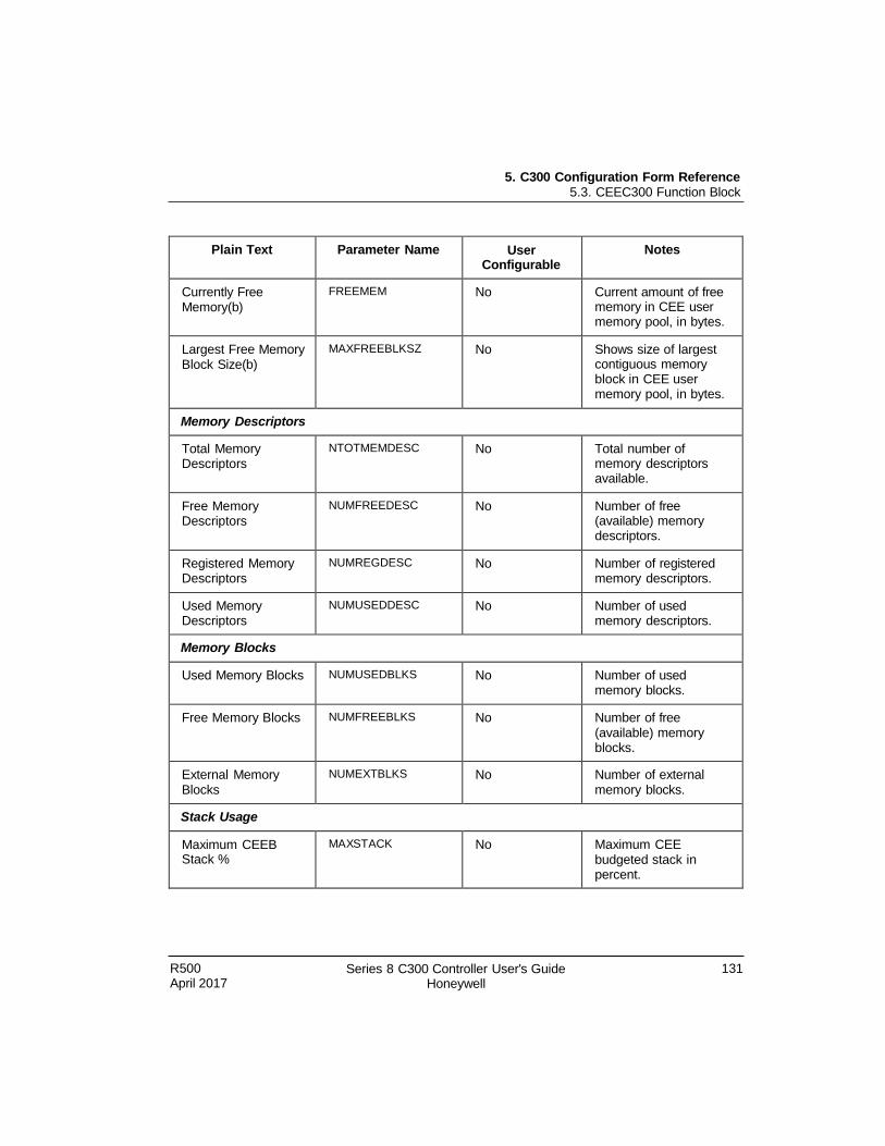
5. C300 Configuration Form Reference 5.3. CEEC300 Function Block
R500 April 2017
Series 8 C300 Controller User's Guide Honeywell
131
Plain Text Parameter Name User Configurable
Notes
Currently Free Memory(b)
FREEMEM No Current amount of free memory in CEE user memory pool, in bytes.
Largest Free Memory Block Size(b)
MAXFREEBLKSZ No Shows size of largest contiguous memory block in CEE user memory pool, in bytes.
Memory Descriptors
Total Memory Descriptors
NTOTMEMDESC No Total number of memory descriptors available.
Free Memory Descriptors
NUMFREEDESC No Number of free (available) memory descriptors.
Registered Memory Descriptors
NUMREGDESC No Number of registered memory descriptors.
Used Memory Descriptors
NUMUSEDDESC No Number of used memory descriptors.
Memory Blocks
Used Memory Blocks NUMUSEDBLKS No Number of used memory blocks.
Free Memory Blocks NUMFREEBLKS No Number of free (available) memory blocks.
External Memory Blocks
NUMEXTBLKS No Number of external memory blocks.
Stack Usage
Maximum CEEB Stack %
MAXSTACK No Maximum CEE budgeted stack in percent.
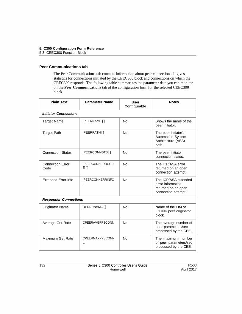
5. C300 Configuration Form Reference 5.3. CEEC300 Function Block
132 Series 8 C300 Controller User's Guide Honeywell
R500 April 2017
Peer Communications tab
The Peer Communications tab contains information about peer connections. It gives
statistics for connections initiated by the CEEC300 block and connections on which the
CEEC300 responds. The following table summarizes the parameter data you can monitor
on the Peer Communications tab of the configuration form for the selected CEEC300
block.
Plain Text Parameter Name User Configurable
Notes
Initiator Connections
Target Name IPEERNAME [ ] No Shows the name of the peer initiator.
Target Path IPEERPATH [ ] No The peer initiator's Automation System Architecture (ASA) path.
Connection Status IPEERCONNSTS [ ] No The peer initiator connection status.
Connection Error Code
IPEERCONNERRCOD E [ ]
No The ICP/ASA error returned on an open connection attempt.
Extended Error Info IPEERCONNERRINFO [ ]
No The ICP/ASA extended error information returned on an open connection attempt.
Responder Connections
Originator Name RPEERNAME [ ] No Name of the FIM or IOLINK peer originator block.
Average Get Rate CPEERAVGPPSCONN [ ]
No The average number of peer parameters/sec processed by the CEE.
Maximum Get Rate CPEERMAXPPSCONN [ ]
No The maximum number of peer parameters/sec processed by the CEE.
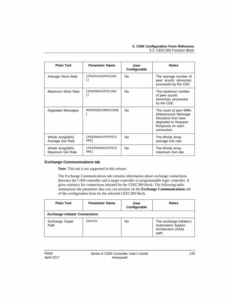
5. C300 Configuration Form Reference 5.3. CEEC300 Function Block
R500 April 2017
Series 8 C300 Controller User's Guide Honeywell
133
Plain Text Parameter Name User Configurable
Notes
Average Store Rate CPEERAVGSPSCONN [ ]
No The average number of peer acyclic stores/sec processed by the CEE.
Maximum Store Rate CPEERMAXSPSCONN [ ]
No The maximum number of peer acyclic stores/sec processed by the CEE.
Degraded Messages RPEERDEGIMRCONN[ ]
No The count of peer IMRs (Interprocess Message Structure) that have degraded to Request- Response on each connection.
Whole Array(WA) Average Get Rate
CPEERWAAVGPPSCO NN[ ]
No The Whole Array average Get rate.
Whole Array(WA) Maximum Get Rate
CPEERWAMAXPPSCO NN[ ]
No The Whole Array maximum Get rate.
Exchange Communications tab
Note: This tab is not supported in this release.
The Exchange Communications tab contains information about exchange connections
between the C300 controller and a target controller or programmable logic controller. It
gives statistics for connections initiated by the CEEC300 block. The following table
summarizes the parameter data you can monitor on the Exchange Communications tab
of the configuration form for the selected CEEC300 block.
Plain Text Parameter Name User Configurable
Notes
Exchange Initiator Connections
Exchange Target Path
EIPATH No The exchange initiator's Automation System Architecture (ASA) path.
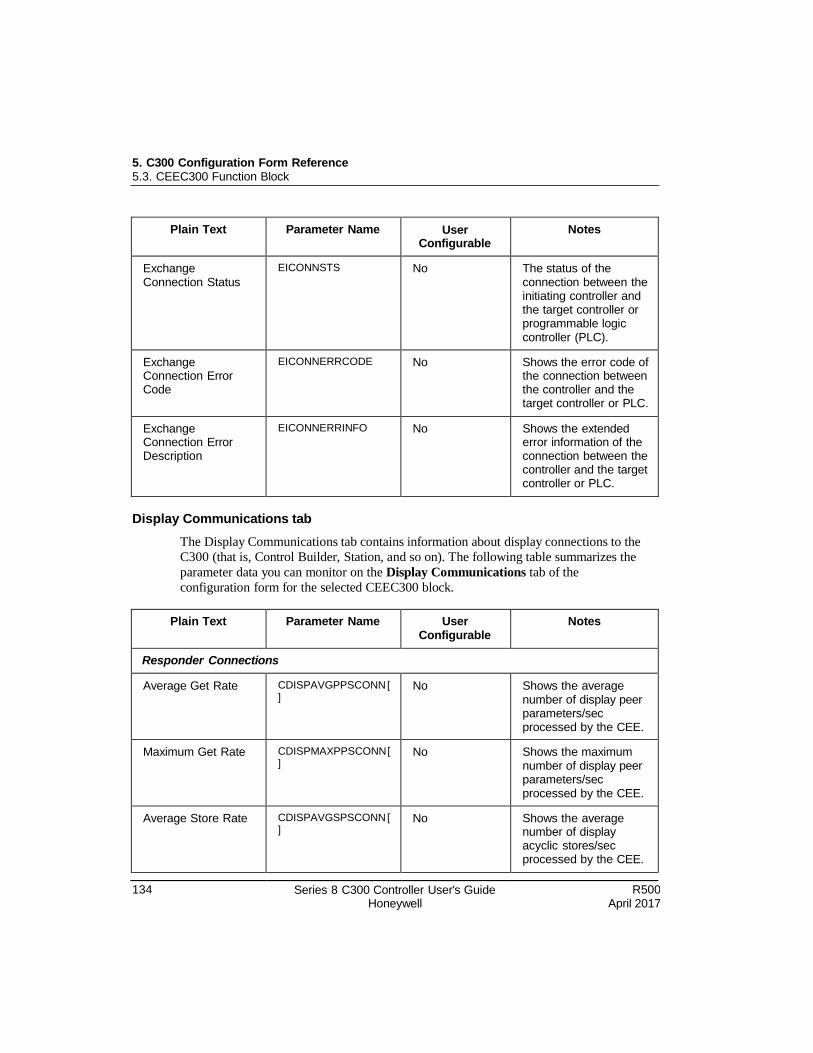
5. C300 Configuration Form Reference 5.3. CEEC300 Function Block
134 Series 8 C300 Controller User's Guide Honeywell
R500 April 2017
Plain Text Parameter Name User Configurable
Notes
Exchange Connection Status
EICONNSTS No The status of the connection between the initiating controller and the target controller or programmable logic controller (PLC).
Exchange Connection Error Code
EICONNERRCODE No Shows the error code of the connection between the controller and the target controller or PLC.
Exchange Connection Error Description
EICONNERRINFO No Shows the extended error information of the connection between the controller and the target controller or PLC.
Display Communications tab
The Display Communications tab contains information about display connections to the
C300 (that is, Control Builder, Station, and so on). The following table summarizes the
parameter data you can monitor on the Display Communications tab of the
configuration form for the selected CEEC300 block.
Plain Text Parameter Name User Configurable
Notes
Responder Connections
Average Get Rate CDISPAVGPPSCONN [ ]
No Shows the average number of display peer parameters/sec processed by the CEE.
Maximum Get Rate CDISPMAXPPSCONN [ ]
No Shows the maximum number of display peer parameters/sec processed by the CEE.
Average Store Rate CDISPAVGSPSCONN [ ]
No Shows the average number of display acyclic stores/sec processed by the CEE.
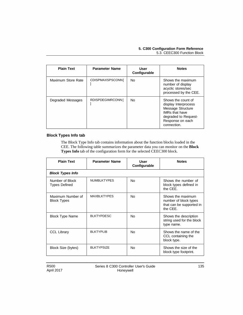
5. C300 Configuration Form Reference 5.3. CEEC300 Function Block
R500 April 2017
Series 8 C300 Controller User's Guide Honeywell
135
Plain Text Parameter Name User Configurable
Notes
Maximum Store Rate CDISPMAXSPSCONN [ ]
No Shows the maximum number of display acyclic stores/sec processed by the CEE.
Degraded Messages RDISPDEGIMRCONN [ ]
No Shows the count of display Interprocess Message Structure IMRs that have degraded to Request- Response on each connection.
Block Types Info tab
The Block Type Info tab contains information about the function blocks loaded in the
CEE. The following table summarizes the parameter data you can monitor on the Block
Types Info tab of the configuration form for the selected CEEC300 block.
Plain Text Parameter Name User Configurable
Notes
Block Types Info
Number of Block Types Defined
NUMBLKTYPES No Shows the number of block types defined in the CEE.
Maximum Number of Block Types
MAXBLKTYPES No Shows the maximum number of block types that can be supported in the CEE.
Block Type Name BLKTYPDESC No Shows the description string used for the block type name.
CCL Library BLKTYPLIB No Shows the name of the CCL containing the block type.
Block Size (bytes) BLKTYPSIZE No Shows the size of the block type footprint.
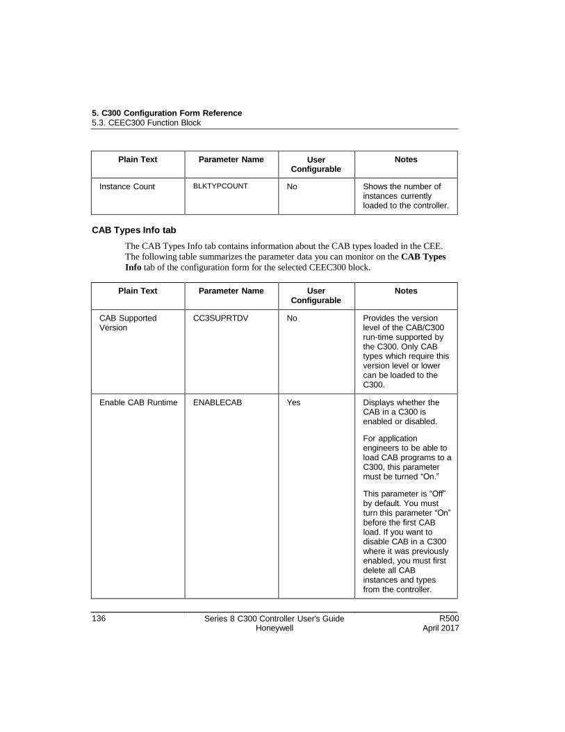
5. C300 Configuration Form Reference 5.3. CEEC300 Function Block
136 Series 8 C300 Controller User's Guide Honeywell
R500 April 2017
Plain Text Parameter Name User Configurable
Notes
Instance Count BLKTYPCOUNT No Shows the number of instances currently loaded to the controller.
CAB Types Info tab
The CAB Types Info tab contains information about the CAB types loaded in the CEE.
The following table summarizes the parameter data you can monitor on the CAB Types
Info tab of the configuration form for the selected CEEC300 block.
Plain Text Parameter Name User Configurable
Notes
CAB Supported Version
CC3SUPRTDV No Provides the version level of the CAB/C300 run-time supported by the C300. Only CAB types which require this version level or lower can be loaded to the C300.
Enable CAB Runtime ENABLECAB Yes Displays whether the CAB in a C300 is enabled or disabled.
For application engineers to be able to load CAB programs to a C300, this parameter must be turned “On.”
This parameter is “Off” by default. You must turn this parameter “On” before the first CAB load. If you want to disable CAB in a C300 where it was previously enabled, you must first delete all CAB instances and types from the controller.
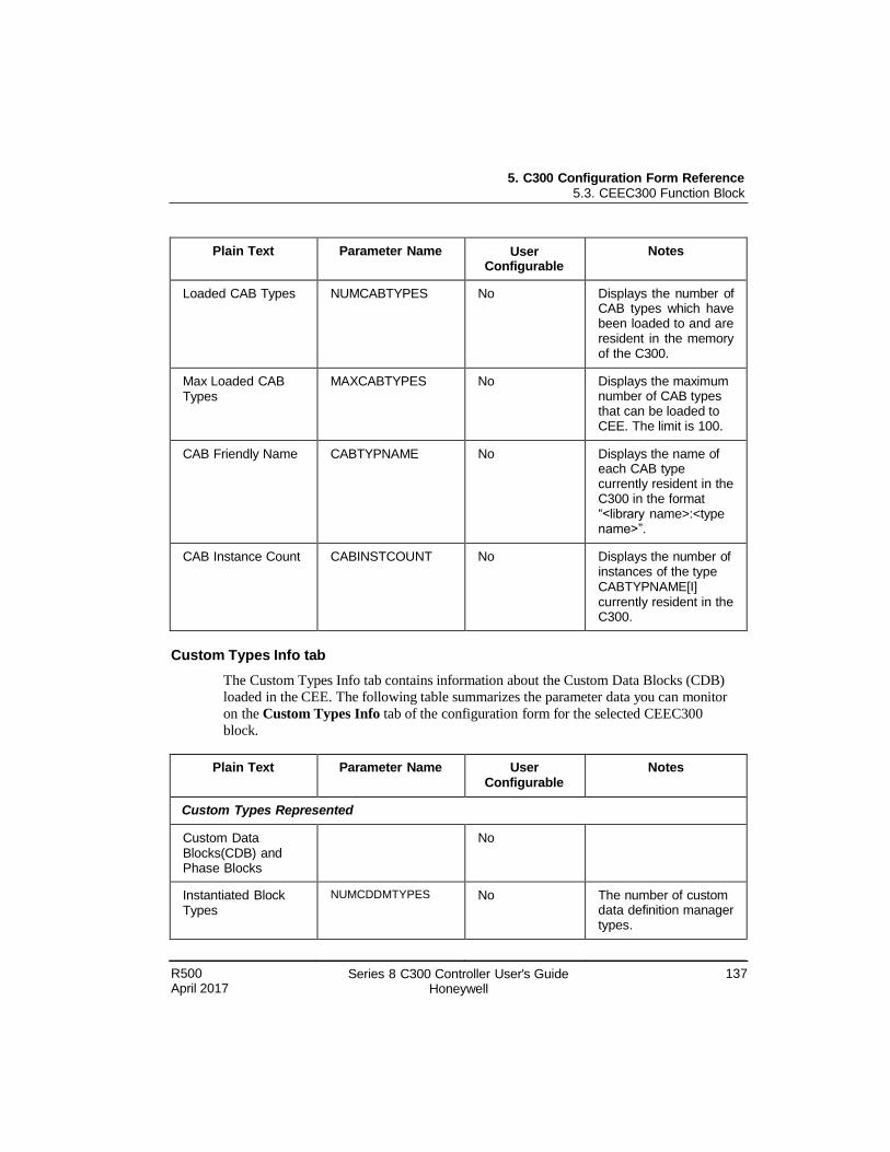
5. C300 Configuration Form Reference 5.3. CEEC300 Function Block
R500 April 2017
Series 8 C300 Controller User's Guide Honeywell
137
Plain Text Parameter Name User Configurable
Notes
Loaded CAB Types NUMCABTYPES No Displays the number of CAB types which have been loaded to and are resident in the memory of the C300.
Max Loaded CAB Types
MAXCABTYPES No Displays the maximum number of CAB types that can be loaded to CEE. The limit is 100.
CAB Friendly Name CABTYPNAME No Displays the name of each CAB type currently resident in the C300 in the format “<library name>:<type name>”.
CAB Instance Count CABINSTCOUNT No Displays the number of instances of the type CABTYPNAME[I] currently resident in the C300.
Custom Types Info tab
The Custom Types Info tab contains information about the Custom Data Blocks (CDB)
loaded in the CEE. The following table summarizes the parameter data you can monitor
on the Custom Types Info tab of the configuration form for the selected CEEC300
block.
Plain Text Parameter Name User Configurable
Notes
Custom Types Represented
Custom Data Blocks(CDB) and Phase Blocks
No
Instantiated Block Types
NUMCDDMTYPES No The number of custom data definition manager types.
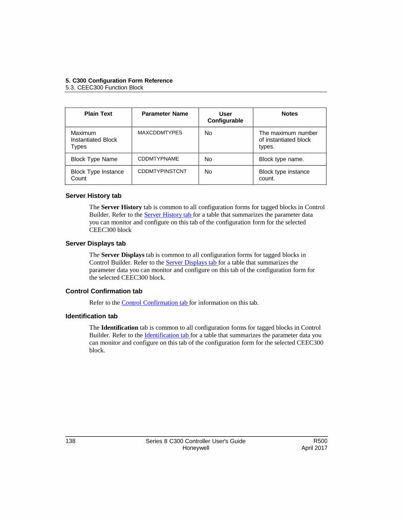
5. C300 Configuration Form Reference 5.3. CEEC300 Function Block
138 Series 8 C300 Controller User's Guide Honeywell
R500 April 2017
Plain Text Parameter Name User Configurable
Notes
Maximum Instantiated Block Types
MAXCDDMTYPES No The maximum number of instantiated block types.
Block Type Name CDDMTYPNAME No Block type name.
Block Type Instance Count
CDDMTYPINSTCNT No Block type instance count.
Server History tab
The Server History tab is common to all configuration forms for tagged blocks in Control
Builder. Refer to the Server History tab for a table that summarizes the parameter data
you can monitor and configure on this tab of the configuration form for the selected
CEEC300 block
Server Displays tab
The Server Displays tab is common to all configuration forms for tagged blocks in
Control Builder. Refer to the Server Displays tab for a table that summarizes the
parameter data you can monitor and configure on this tab of the configuration form for
the selected CEEC300 block.
Control Confirmation tab
Refer to the Control Confirmation tab for information on this tab.
Identification tab
The Identification tab is common to all configuration forms for tagged blocks in Control
Builder. Refer to the Identification tab for a table that summarizes the parameter data you
can monitor and configure on this tab of the configuration form for the selected CEEC300
block.
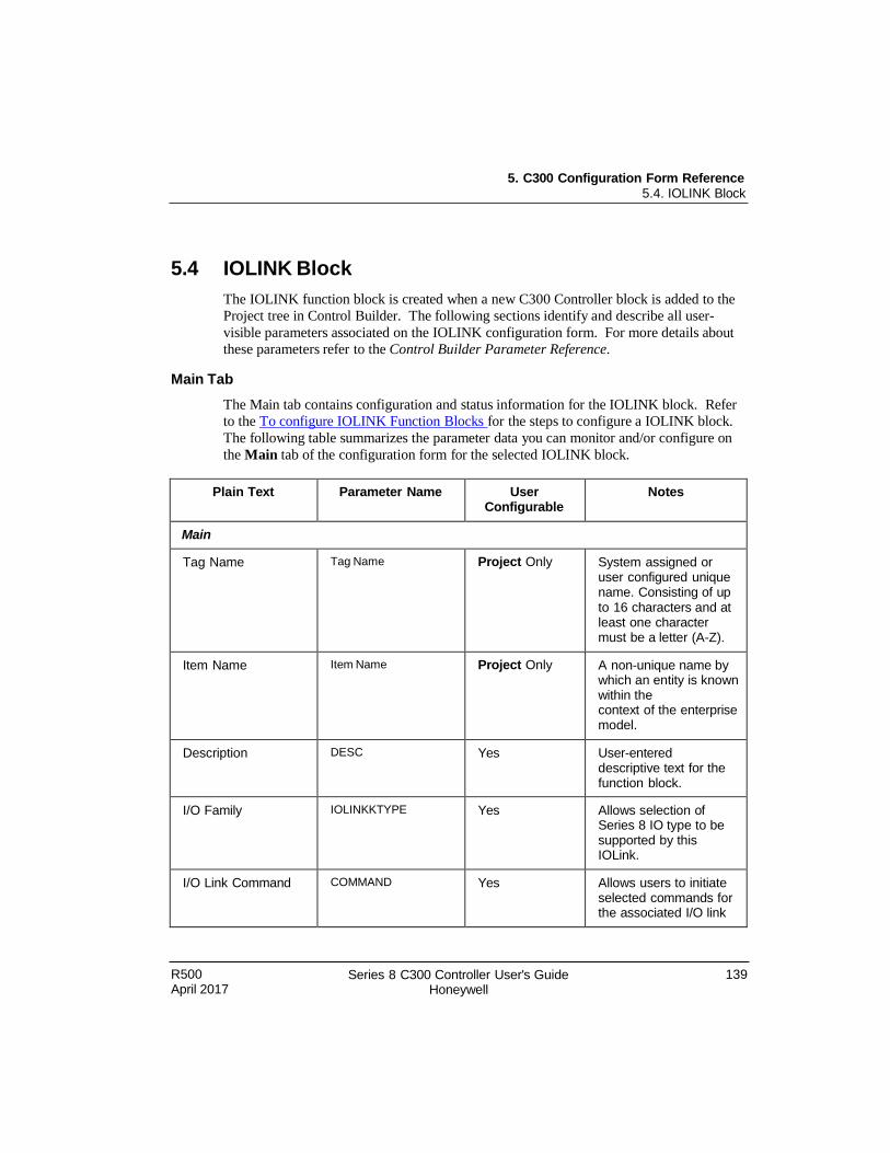
R500 April 2017
Series 8 C300 Controller User's Guide Honeywell
139
5. C300 Configuration Form Reference 5.4. IOLINK Block
5.4 IOLINK Block
The IOLINK function block is created when a new C300 Controller block is added to the
Project tree in Control Builder. The following sections identify and describe all user-
visible parameters associated on the IOLINK configuration form. For more details about
these parameters refer to the Control Builder Parameter Reference.
Main Tab
The Main tab contains configuration and status information for the IOLINK block. Refer
to the To configure IOLINK Function Blocks for the steps to configure a IOLINK block.
The following table summarizes the parameter data you can monitor and/or configure on
the Main tab of the configuration form for the selected IOLINK block.
Plain Text Parameter Name User Configurable
Notes
Main
Tag Name Tag Name Project Only System assigned or user configured unique name. Consisting of up to 16 characters and at least one character must be a letter (A-Z).
Item Name Item Name Project Only A non-unique name by which an entity is known within the context of the enterprise model.
Description DESC Yes User-entered descriptive text for the function block.
I/O Family IOLINKKTYPE Yes Allows selection of Series 8 IO type to be supported by this IOLink.
I/O Link Command COMMAND Yes Allows users to initiate selected commands for the associated I/O link
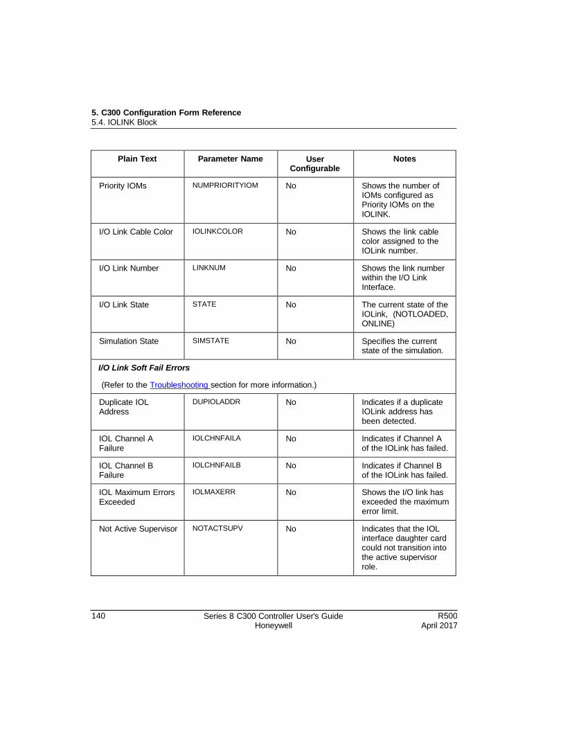
5. C300 Configuration Form Reference 5.4. IOLINK Block
140 Series 8 C300 Controller User's Guide Honeywell
R500 April 2017
Plain Text Parameter Name User Configurable
Notes
Priority IOMs NUMPRIORITYIOM No Shows the number of IOMs configured as Priority IOMs on the IOLINK.
I/O Link Cable Color IOLINKCOLOR No Shows the link cable color assigned to the IOLink number.
I/O Link Number LINKNUM No Shows the link number within the I/O Link Interface.
I/O Link State STATE No The current state of the IOLink, (NOTLOADED, ONLINE)
Simulation State SIMSTATE No Specifies the current state of the simulation.
I/O Link Soft Fail Errors
(Refer to the Troubleshooting section for more information.)
Duplicate IOL Address
DUPIOLADDR No Indicates if a duplicate IOLink address has been detected.
IOL Channel A Failure
IOLCHNFAILA No Indicates if Channel A of the IOLink has failed.
IOL Channel B Failure
IOLCHNFAILB No Indicates if Channel B of the IOLink has failed.
IOL Maximum Errors Exceeded
IOLMAXERR No Shows the I/O link has exceeded the maximum error limit.
Not Active Supervisor NOTACTSUPV No Indicates that the IOL interface daughter card could not transition into the active supervisor role.
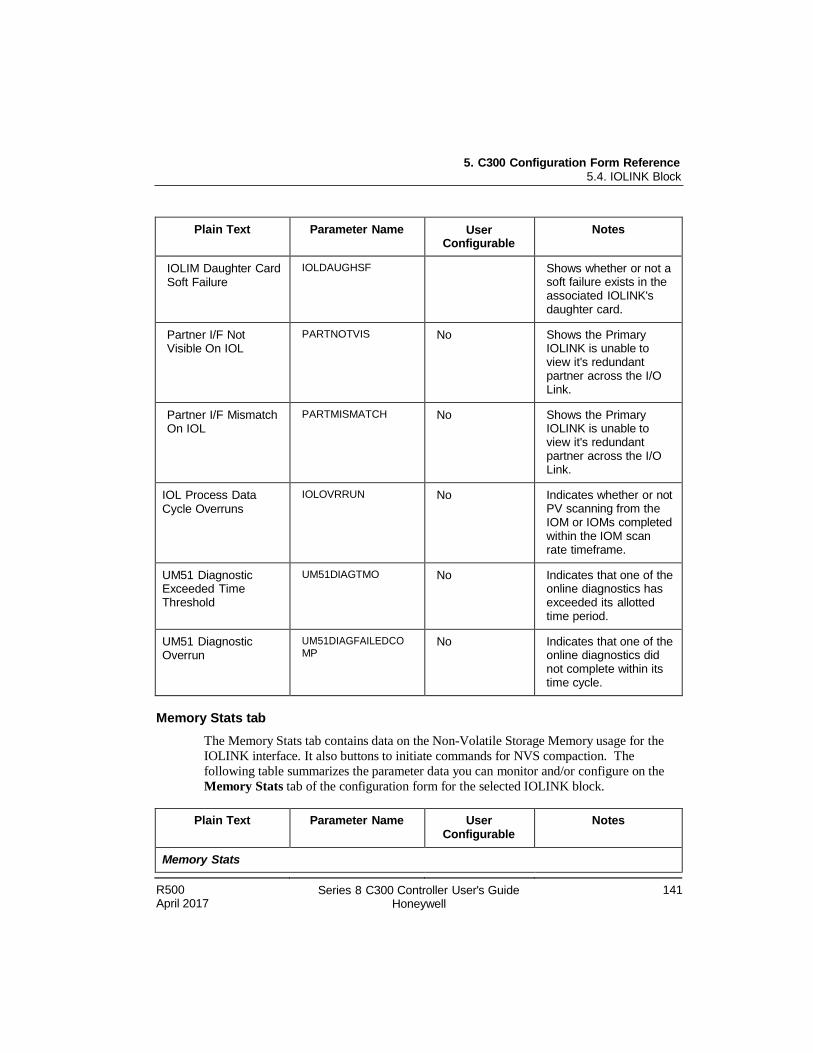
5. C300 Configuration Form Reference 5.4. IOLINK Block
R500 April 2017
Series 8 C300 Controller User's Guide Honeywell
141
Plain Text Parameter Name User Configurable
Notes
IOLIM Daughter Card Soft Failure
IOLDAUGHSF Shows whether or not a soft failure exists in the associated IOLINK's daughter card.
Partner I/F Not Visible On IOL
PARTNOTVIS No Shows the Primary IOLINK is unable to view it's redundant partner across the I/O Link.
Partner I/F Mismatch On IOL
PARTMISMATCH No Shows the Primary IOLINK is unable to view it's redundant partner across the I/O Link.
IOL Process Data Cycle Overruns
IOLOVRRUN No Indicates whether or not PV scanning from the IOM or IOMs completed within the IOM scan rate timeframe.
UM51 Diagnostic Exceeded Time Threshold
UM51DIAGTMO No Indicates that one of the online diagnostics has exceeded its allotted time period.
UM51 Diagnostic Overrun
UM51DIAGFAILEDCO MP
No Indicates that one of the online diagnostics did not complete within its time cycle.
Memory Stats tab
The Memory Stats tab contains data on the Non-Volatile Storage Memory usage for the
IOLINK interface. It also buttons to initiate commands for NVS compaction. The
following table summarizes the parameter data you can monitor and/or configure on the
Memory Stats tab of the configuration form for the selected IOLINK block.
Plain Text Parameter Name User Configurable
Notes
Memory Stats
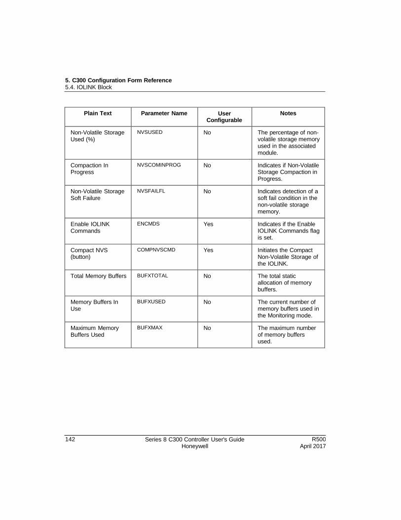
5. C300 Configuration Form Reference 5.4. IOLINK Block
142 Series 8 C300 Controller User's Guide Honeywell
R500 April 2017
Plain Text Parameter Name User Configurable
Notes
Non-Volatile Storage Used (%)
NVSUSED No The percentage of non- volatile storage memory used in the associated module.
Compaction In Progress
NVSCOMINPROG No Indicates if Non-Volatile Storage Compaction in Progress.
Non-Volatile Storage Soft Failure
NVSFAILFL No Indicates detection of a soft fail condition in the non-volatile storage memory.
Enable IOLINK Commands
ENCMDS Yes Indicates if the Enable IOLINK Commands flag is set.
Compact NVS (button)
COMPNVSCMD Yes Initiates the Compact Non-Volatile Storage of the IOLINK.
Total Memory Buffers BUFXTOTAL No The total static allocation of memory buffers.
Memory Buffers In Use
BUFXUSED No The current number of memory buffers used in the Monitoring mode.
Maximum Memory Buffers Used
BUFXMAX No The maximum number of memory buffers used.
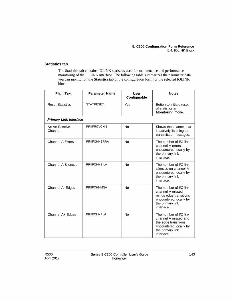
5. C300 Configuration Form Reference 5.4. IOLINK Block
R500 April 2017
Series 8 C300 Controller User's Guide Honeywell
143
Statistics tab
The Statistics tab contains IOLINK statistics used for maintenance and performance
monitoring of the IOLINK interface. The following table summarizes the parameter data
you can monitor on the Statistics tab of the configuration form for the selected IOLINK
block.
Plain Text Parameter Name User Configurable
Notes
Reset Statistics STATRESET Yes Button to initiate reset of statistics in Monitoring mode.
Primary Link Interface
Active Receive Channel
PRIIFRCVCHN No Shows the channel that is actively listening to transmitted messages.
Channel A Errors PRIIFCHNERRA No The number of I/O link channel A errors encountered locally by the primary link interface.
Channel A Silences PRIIFCHNSILA No The number of I/O link silences on channel A encountered locally by the primary link interface.
Channel A- Edges PRIIFCHNMNA No The number of I/O link channel A missed minus edge transitions encountered locally by the primary link interface.
Channel A+ Edges PRIIFCHNPLA No The number of I/O link channel A missed and the edge transitions encountered locally by the primary link interface.
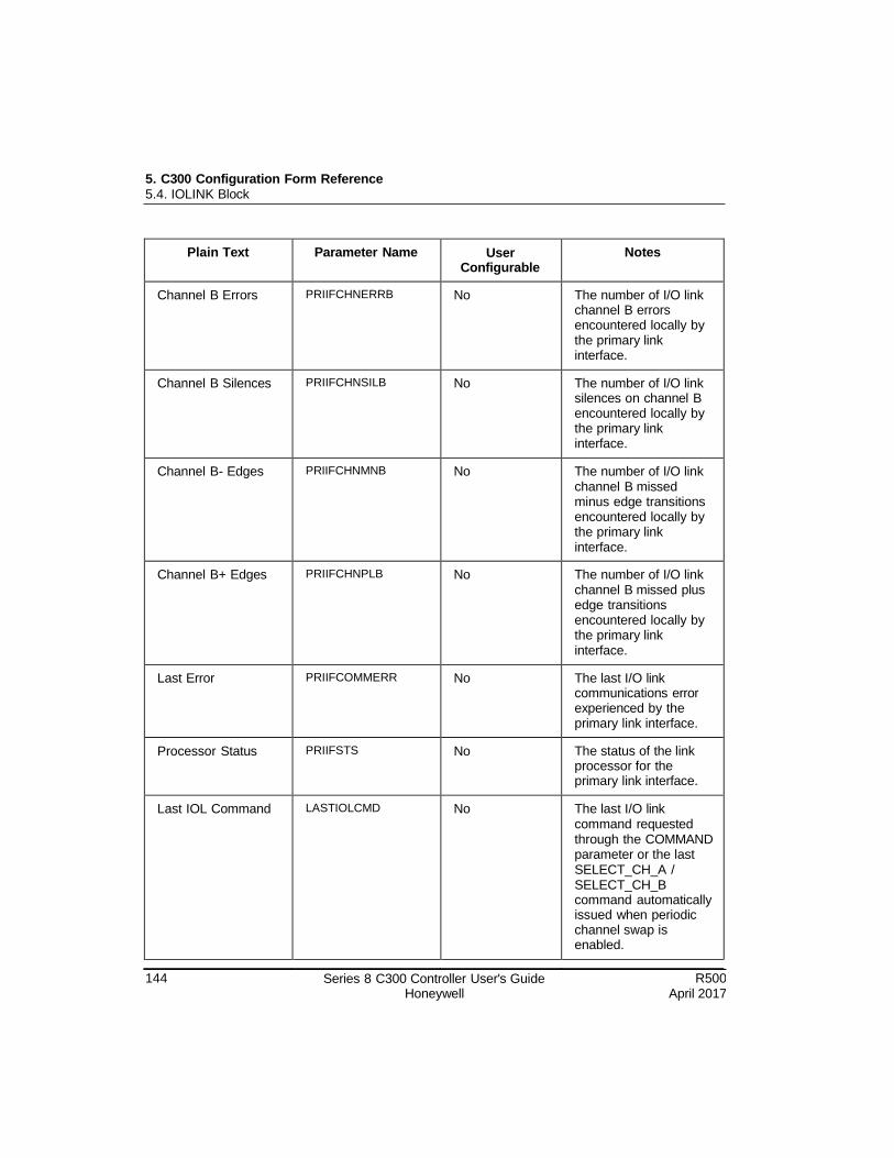
5. C300 Configuration Form Reference 5.4. IOLINK Block
144 Series 8 C300 Controller User's Guide Honeywell
R500 April 2017
Plain Text Parameter Name User Configurable
Notes
Channel B Errors PRIIFCHNERRB No The number of I/O link channel B errors encountered locally by the primary link interface.
Channel B Silences PRIIFCHNSILB No The number of I/O link silences on channel B encountered locally by the primary link interface.
Channel B- Edges PRIIFCHNMNB No The number of I/O link channel B missed minus edge transitions encountered locally by the primary link interface.
Channel B+ Edges PRIIFCHNPLB No The number of I/O link channel B missed plus edge transitions encountered locally by the primary link interface.
Last Error PRIIFCOMMERR No The last I/O link communications error experienced by the primary link interface.
Processor Status PRIIFSTS No The status of the link processor for the primary link interface.
Last IOL Command LASTIOLCMD No The last I/O link command requested through the COMMAND parameter or the last SELECT_CH_A / SELECT_CH_B command automatically issued when periodic channel swap is enabled.
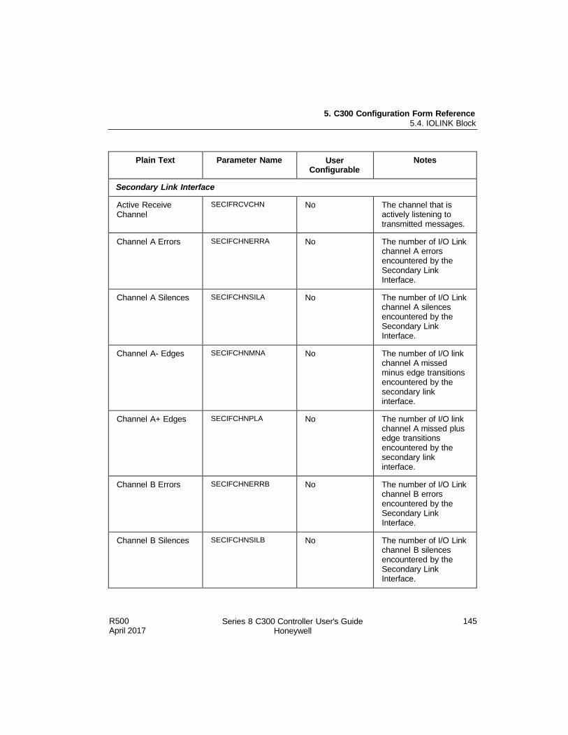
5. C300 Configuration Form Reference 5.4. IOLINK Block
R500 April 2017
Series 8 C300 Controller User's Guide Honeywell
145
Plain Text Parameter Name User Configurable
Notes
Secondary Link Interface
Active Receive Channel
SECIFRCVCHN No The channel that is actively listening to transmitted messages.
Channel A Errors SECIFCHNERRA No The number of I/O Link channel A errors encountered by the Secondary Link Interface.
Channel A Silences SECIFCHNSILA No The number of I/O Link channel A silences encountered by the Secondary Link Interface.
Channel A- Edges SECIFCHNMNA No The number of I/O link channel A missed minus edge transitions encountered by the secondary link interface.
Channel A+ Edges SECIFCHNPLA No The number of I/O link channel A missed plus edge transitions encountered by the secondary link interface.
Channel B Errors SECIFCHNERRB No The number of I/O Link channel B errors encountered by the Secondary Link Interface.
Channel B Silences SECIFCHNSILB No The number of I/O Link channel B silences encountered by the Secondary Link Interface.
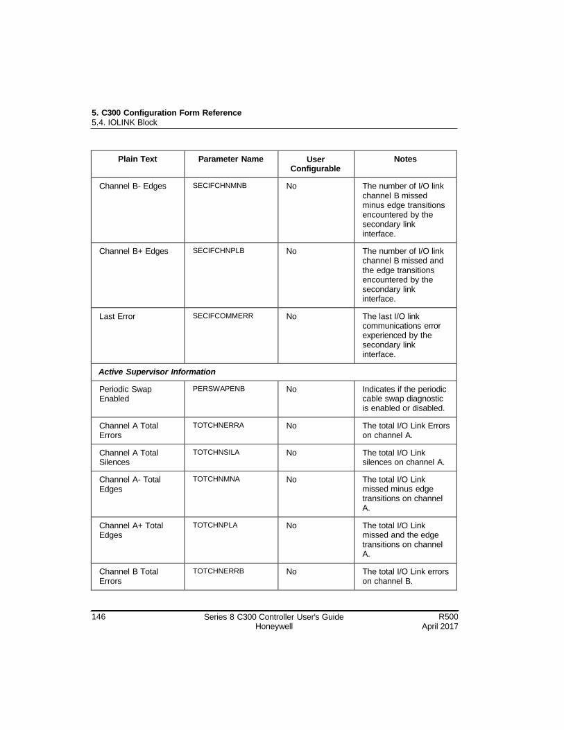
5. C300 Configuration Form Reference 5.4. IOLINK Block
146 Series 8 C300 Controller User's Guide Honeywell
R500 April 2017
Plain Text Parameter Name User Configurable
Notes
Channel B- Edges SECIFCHNMNB No The number of I/O link channel B missed minus edge transitions encountered by the secondary link interface.
Channel B+ Edges SECIFCHNPLB No The number of I/O link channel B missed and the edge transitions encountered by the secondary link interface.
Last Error SECIFCOMMERR No The last I/O link communications error experienced by the secondary link interface.
Active Supervisor Information
Periodic Swap Enabled
PERSWAPENB No Indicates if the periodic cable swap diagnostic is enabled or disabled.
Channel A Total Errors
TOTCHNERRA No The total I/O Link Errors on channel A.
Channel A Total Silences
TOTCHNSILA No The total I/O Link silences on channel A.
Channel A- Total Edges
TOTCHNMNA No The total I/O Link missed minus edge transitions on channel A.
Channel A+ Total Edges
TOTCHNPLA No The total I/O Link missed and the edge transitions on channel A.
Channel B Total Errors
TOTCHNERRB No The total I/O Link errors on channel B.
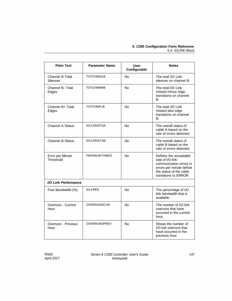
5. C300 Configuration Form Reference 5.4. IOLINK Block
R500 April 2017
Series 8 C300 Controller User's Guide Honeywell
147
Plain Text Parameter Name User Configurable
Notes
Channel B Total Silences
TOTCHNSILB No The total I/O Link silences on channel B.
Channel B- Total Edges
TOTCHNMNB No The total I/O Link missed minus edge transitions on channel B.
Channel B+ Total Edges
TOTCHNPLB No The total I/O Link missed plus edge transitions on channel B.
Channel A Status IOLCHNSTSA No The overall status of cable A based on the rate of errors detected.
Channel B Status IOLCHNSTSB No The overall status of cable B based on the rate of errors detected.
Error per Minute Threshold
PERSWAPTHRES No Defines the acceptable rate of I/O link communication errors in errors per minute before the status of the cable transitions to ERROR.
I/O Link Performance
Free Bandwidth (%) IOLFREE No The percentage of I/O link bandwidth that is available.
Overruns - Current Hour
OVERRUNSCUR No The number of I/O link overruns that have occurred in the current hour.
Overruns - Previous Hour
OVERRUNSPREV No Shows the number of I/O link overruns that have occurred in the previous hour.
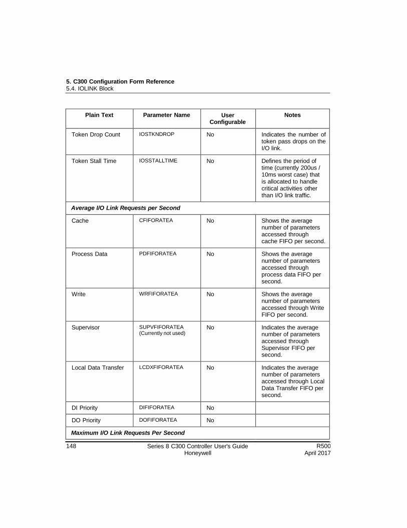
5. C300 Configuration Form Reference 5.4. IOLINK Block
148 Series 8 C300 Controller User's Guide Honeywell
R500 April 2017
Plain Text Parameter Name User Configurable
Notes
Token Drop Count IOSTKNDROP No Indicates the number of token pass drops on the I/O link.
Token Stall Time IOSSTALLTIME No Defines the period of time (currently 200us / 10ms worst case) that is allocated to handle critical activities other than I/O link traffic.
Average I/O Link Requests per Second
Cache CFIFORATEA No Shows the average number of parameters accessed through cache FIFO per second.
Process Data PDFIFORATEA No Shows the average number of parameters accessed through process data FIFO per second.
Write WRFIFORATEA No Shows the average number of parameters accessed through Write FIFO per second.
Supervisor SUPVFIFORATEA (Currently not used)
No Indicates the average number of parameters accessed through Supervisor FIFO per second.
Local Data Transfer LCDXFIFORATEA No Indicates the average number of parameters accessed through Local Data Transfer FIFO per second.
DI Priority DIFIFORATEA No
DO Priority DOFIFORATEA No
Maximum I/O Link Requests Per Second
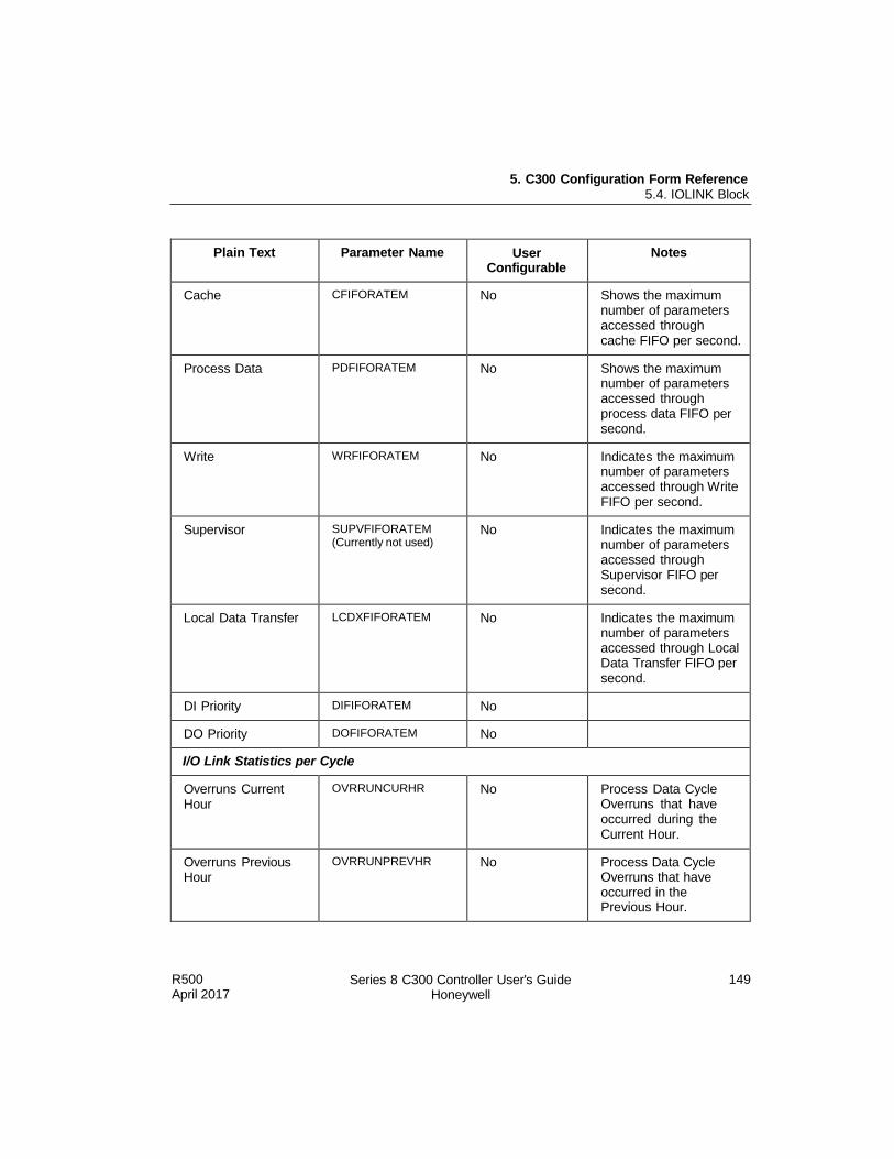
5. C300 Configuration Form Reference 5.4. IOLINK Block
R500 April 2017
Series 8 C300 Controller User's Guide Honeywell
149
Plain Text Parameter Name User Configurable
Notes
Cache CFIFORATEM No Shows the maximum number of parameters accessed through cache FIFO per second.
Process Data PDFIFORATEM No Shows the maximum number of parameters accessed through process data FIFO per second.
Write WRFIFORATEM No Indicates the maximum number of parameters accessed through Write FIFO per second.
Supervisor SUPVFIFORATEM (Currently not used)
No Indicates the maximum number of parameters accessed through Supervisor FIFO per second.
Local Data Transfer LCDXFIFORATEM No Indicates the maximum number of parameters accessed through Local Data Transfer FIFO per second.
DI Priority DIFIFORATEM No
DO Priority DOFIFORATEM No
I/O Link Statistics per Cycle
Overruns Current Hour
OVRRUNCURHR No Process Data Cycle Overruns that have occurred during the Current Hour.
Overruns Previous Hour
OVRRUNPREVHR No Process Data Cycle Overruns that have occurred in the Previous Hour.
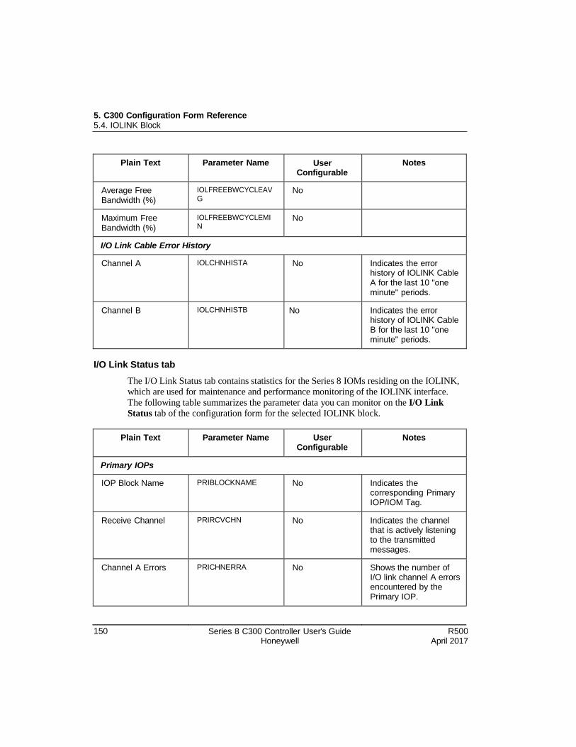
5. C300 Configuration Form Reference 5.4. IOLINK Block
150 Series 8 C300 Controller User's Guide Honeywell
R500 April 2017
Plain Text Parameter Name User Configurable
Notes
Average Free Bandwidth (%)
IOLFREEBWCYCLEAV G
No
Maximum Free Bandwidth (%)
IOLFREEBWCYCLEMI N
No
I/O Link Cable Error History
Channel A IOLCHNHISTA No Indicates the error history of IOLINK Cable A for the last 10 "one minute" periods.
Channel B IOLCHNHISTB No Indicates the error history of IOLINK Cable B for the last 10 "one minute" periods.
I/O Link Status tab
The I/O Link Status tab contains statistics for the Series 8 IOMs residing on the IOLINK,
which are used for maintenance and performance monitoring of the IOLINK interface.
The following table summarizes the parameter data you can monitor on the I/O Link
Status tab of the configuration form for the selected IOLINK block.
Plain Text Parameter Name User Configurable
Notes
Primary IOPs
IOP Block Name PRIBLOCKNAME No Indicates the corresponding Primary IOP/IOM Tag.
Receive Channel PRIRCVCHN No Indicates the channel that is actively listening to the transmitted messages.
Channel A Errors PRICHNERRA No Shows the number of I/O link channel A errors encountered by the Primary IOP.
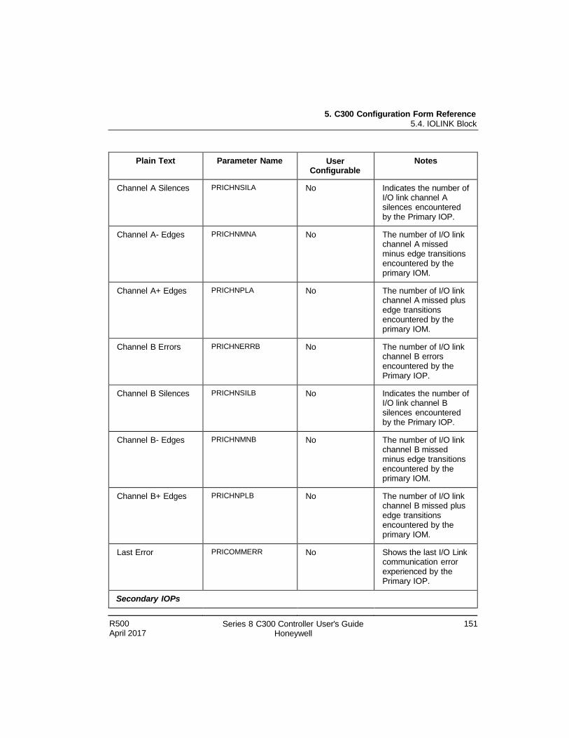
5. C300 Configuration Form Reference 5.4. IOLINK Block
R500 April 2017
Series 8 C300 Controller User's Guide Honeywell
151
Plain Text Parameter Name User Configurable
Notes
Channel A Silences PRICHNSILA No Indicates the number of I/O link channel A silences encountered by the Primary IOP.
Channel A- Edges PRICHNMNA No The number of I/O link channel A missed minus edge transitions encountered by the primary IOM.
Channel A+ Edges PRICHNPLA No The number of I/O link channel A missed plus edge transitions encountered by the primary IOM.
Channel B Errors PRICHNERRB No The number of I/O link channel B errors encountered by the Primary IOP.
Channel B Silences PRICHNSILB No Indicates the number of I/O link channel B silences encountered by the Primary IOP.
Channel B- Edges PRICHNMNB No The number of I/O link channel B missed minus edge transitions encountered by the primary IOM.
Channel B+ Edges PRICHNPLB No The number of I/O link channel B missed plus edge transitions encountered by the primary IOM.
Last Error PRICOMMERR No Shows the last I/O Link communication error experienced by the Primary IOP.
Secondary IOPs
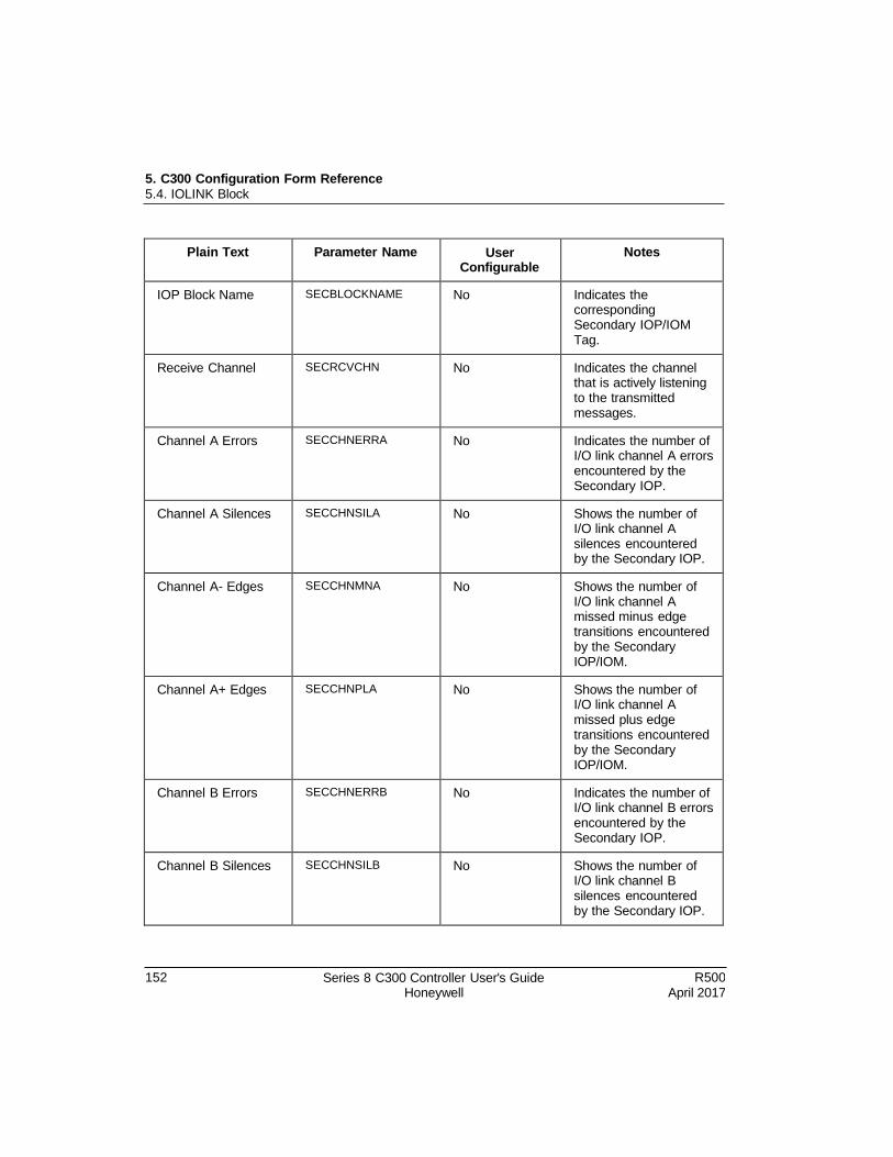
5. C300 Configuration Form Reference 5.4. IOLINK Block
152 Series 8 C300 Controller User's Guide Honeywell
R500 April 2017
Plain Text Parameter Name User Configurable
Notes
IOP Block Name SECBLOCKNAME No Indicates the corresponding Secondary IOP/IOM Tag.
Receive Channel SECRCVCHN No Indicates the channel that is actively listening to the transmitted messages.
Channel A Errors SECCHNERRA No Indicates the number of I/O link channel A errors encountered by the Secondary IOP.
Channel A Silences SECCHNSILA No Shows the number of I/O link channel A silences encountered by the Secondary IOP.
Channel A- Edges SECCHNMNA No Shows the number of I/O link channel A missed minus edge transitions encountered by the Secondary IOP/IOM.
Channel A+ Edges SECCHNPLA No Shows the number of I/O link channel A missed plus edge transitions encountered by the Secondary IOP/IOM.
Channel B Errors SECCHNERRB No Indicates the number of I/O link channel B errors encountered by the Secondary IOP.
Channel B Silences SECCHNSILB No Shows the number of I/O link channel B silences encountered by the Secondary IOP.
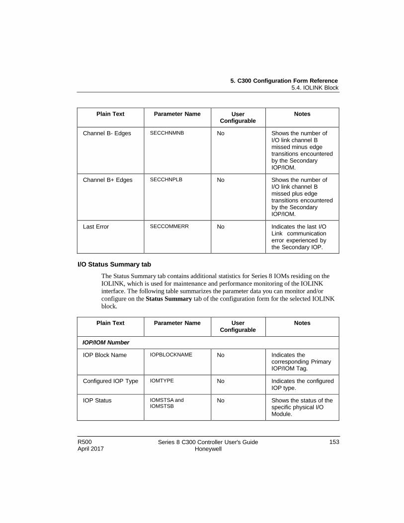
5. C300 Configuration Form Reference 5.4. IOLINK Block
R500 April 2017
Series 8 C300 Controller User's Guide Honeywell
153
Plain Text Parameter Name User Configurable
Notes
Channel B- Edges SECCHNMNB No Shows the number of I/O link channel B missed minus edge transitions encountered by the Secondary IOP/IOM.
Channel B+ Edges SECCHNPLB No Shows the number of I/O link channel B missed plus edge transitions encountered by the Secondary IOP/IOM.
Last Error SECCOMMERR No Indicates the last I/O Link communication error experienced by the Secondary IOP.
I/O Status Summary tab
The Status Summary tab contains additional statistics for Series 8 IOMs residing on the
IOLINK, which is used for maintenance and performance monitoring of the IOLINK
interface. The following table summarizes the parameter data you can monitor and/or
configure on the Status Summary tab of the configuration form for the selected IOLINK
block.
Plain Text Parameter Name User Configurable
Notes
IOP/IOM Number
IOP Block Name IOPBLOCKNAME No Indicates the corresponding Primary IOP/IOM Tag.
Configured IOP Type IOMTYPE No Indicates the configured IOP type.
IOP Status IOMSTSA and IOMSTSB
No Shows the status of the specific physical I/O Module.

5. C300 Configuration Form Reference 5.4. IOLINK Block
154 Series 8 C300 Controller User's Guide Honeywell
R500 April 2017
Plain Text Parameter Name User Configurable
Notes
Database Valid DBVALID No Indicates whether the user has validated the IOP database configuration.
Acting Primary Module
ACTPRIM No Indicates the acting primary I/O module.
Synchronization Status
SYNCHSTS No Indicates Primary/Secondary IOP Database Synchronization Status.
IOM Commands IOMCOMMAND No Allows users to initiate selected commands for the associated redundant I/O Processor (IOP) pair or single IOP.
Physical Bias State WITHBIASENM No Indicates that the preferred primary is really the acting primary.
I/O Link Scan Rate SCANRATE No Shows how often periodic process data is collected from the IOPs and published to the controller.
Overruns - Current Hour
IOPORCUR No Indicates the number of I/O Link overruns that have occurred in the current hour.
Overruns - Previous Hour
IOPORPREV No Indicates the number of I/O Link overruns that have occurred in the previous hour.
Cached Parameters NUMCACHE No The number of cached parameters residing in the IOLINK.
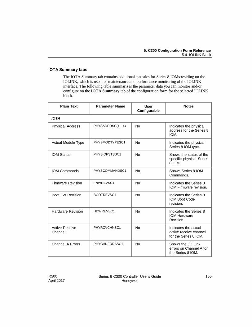
5. C300 Configuration Form Reference 5.4. IOLINK Block
R500 April 2017
Series 8 C300 Controller User's Guide Honeywell
155
IOTA Summary tabs
The IOTA Summary tab contains additional statistics for Series 8 IOMs residing on the
IOLINK, which is used for maintenance and performance monitoring of the IOLINK
interface. The following table summarizes the parameter data you can monitor and/or
configure on the IOTA Summary tab of the configuration form for the selected IOLINK
block.
Plain Text Parameter Name User Configurable
Notes
IOTA
Physical Address PHYSADDRSC(1…4) No Indicates the physical address for the Series 8 IOM.
Actual Module Type PHYSMODTYPESC1 No Indicates the physical Series 8 IOM type.
IOM Status PHYSIOPSTSSC1 No Shows the status of the specific physical Series 8 IOM.
IOM Commands PHYSCOMMANDSC1 No Shows Series 8 IOM Commands.
Firmware Revision FNWREVSC1 No Indicates the Series 8 IOM Firmware revision.
Boot FW Revision BOOTREVSC1 No Indicates the Series 8 IOM Boot Code revision.
Hardware Revision HDWREVSC1 No Indicates the Series 8 IOM Hardware Revision.
Active Receive Channel
PHYRCVCHNSC1 No Indicates the actual active receive channel for the Series 8 IOM.
Channel A Errors PHYCHNERRASC1 No Shows the I/O Link errors on Channel A for the Series 8 IOM.
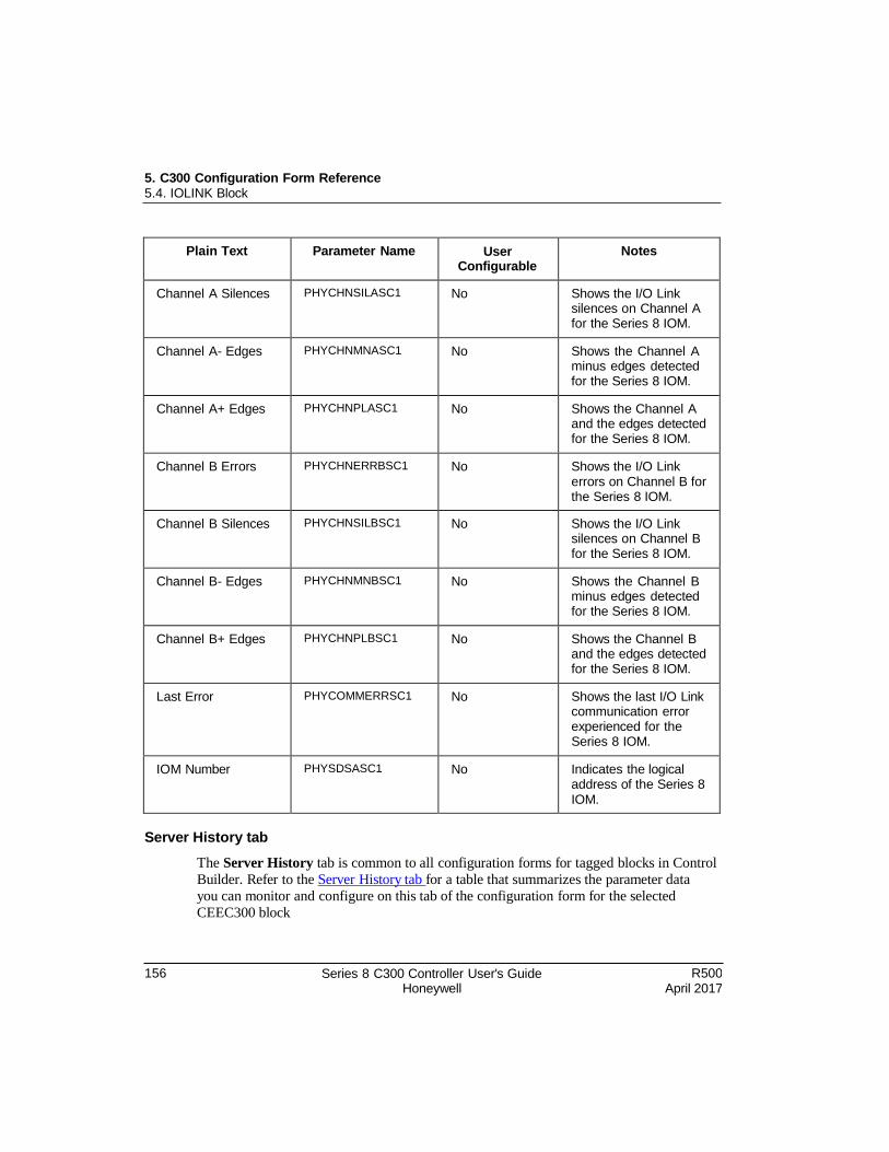
5. C300 Configuration Form Reference 5.4. IOLINK Block
156 Series 8 C300 Controller User's Guide Honeywell
R500 April 2017
Plain Text Parameter Name User Configurable
Notes
Channel A Silences PHYCHNSILASC1 No Shows the I/O Link silences on Channel A for the Series 8 IOM.
Channel A- Edges PHYCHNMNASC1 No Shows the Channel A minus edges detected for the Series 8 IOM.
Channel A+ Edges PHYCHNPLASC1 No Shows the Channel A and the edges detected for the Series 8 IOM.
Channel B Errors PHYCHNERRBSC1 No Shows the I/O Link errors on Channel B for the Series 8 IOM.
Channel B Silences PHYCHNSILBSC1 No Shows the I/O Link silences on Channel B for the Series 8 IOM.
Channel B- Edges PHYCHNMNBSC1 No Shows the Channel B minus edges detected for the Series 8 IOM.
Channel B+ Edges PHYCHNPLBSC1 No Shows the Channel B and the edges detected for the Series 8 IOM.
Last Error PHYCOMMERRSC1 No Shows the last I/O Link communication error experienced for the Series 8 IOM.
IOM Number PHYSDSASC1 No Indicates the logical address of the Series 8 IOM.
Server History tab
The Server History tab is common to all configuration forms for tagged blocks in Control
Builder. Refer to the Server History tab for a table that summarizes the parameter data
you can monitor and configure on this tab of the configuration form for the selected
CEEC300 block
5. C300 Configuration Form Reference 5.4. IOLINK Block
R500 April 2017
Series 8 C300 Controller User's Guide Honeywell
157
Server Displays tab
The Server Displays tab is common to all configuration forms for tagged blocks in
Control Builder. Refer to the Server Displays tab for a table that summarizes the
parameter data you can monitor and configure on this tab of the configuration form for
the selected CEEC300 block.
Control Confirmation tab
Refer to the Control Confirmation tab for information on this tab.
Identification tab
The Identification tab is common to all configuration forms for tagged blocks in Control
Builder. Refer to the Identification tab for a table that summarizes the parameter data you
can monitor and configure on this tab of the configuration form for the selected CEEC300
block.

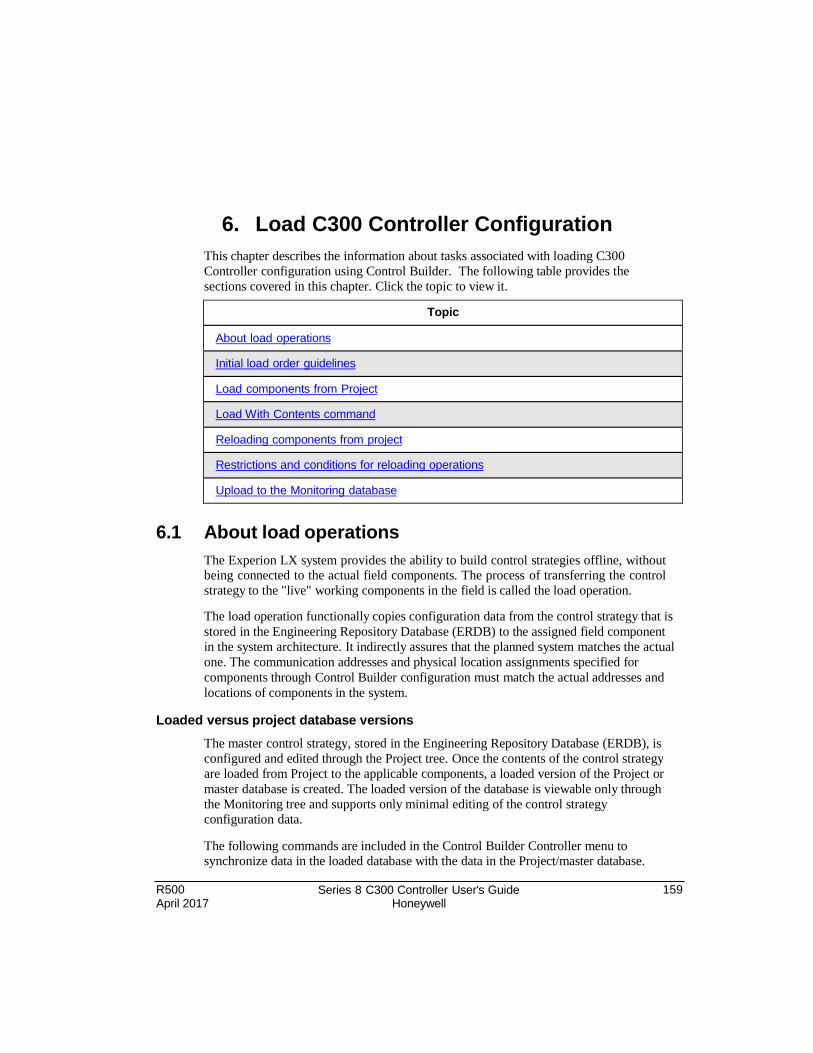
R500 April 2017
Series 8 C300 Controller User's Guide Honeywell
159
6. Load C300 Controller Configuration
This chapter describes the information about tasks associated with loading C300
Controller configuration using Control Builder. The following table provides the
sections covered in this chapter. Click the topic to view it.
Topic
About load operations
Initial load order guidelines
Load components from Project
Load With Contents command
Reloading components from project
Restrictions and conditions for reloading operations
Upload to the Monitoring database
6.1 About load operations
The Experion LX system provides the ability to build control strategies offline, without being connected to the actual field components. The process of transferring the control
strategy to the "live" working components in the field is called the load operation.
The load operation functionally copies configuration data from the control strategy that is
stored in the Engineering Repository Database (ERDB) to the assigned field component
in the system architecture. It indirectly assures that the planned system matches the actual
one. The communication addresses and physical location assignments specified for
components through Control Builder configuration must match the actual addresses and
locations of components in the system.
Loaded versus project database versions
The master control strategy, stored in the Engineering Repository Database (ERDB), is
configured and edited through the Project tree. Once the contents of the control strategy
are loaded from Project to the applicable components, a loaded version of the Project or
master database is created. The loaded version of the database is viewable only through
the Monitoring tree and supports only minimal editing of the control strategy
configuration data.
The following commands are included in the Control Builder Controller menu to synchronize data in the loaded database with the data in the Project/master database.
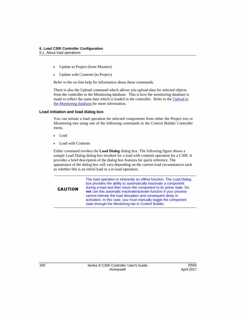
160 Series 8 C300 Controller User's Guide Honeywell
R500 April 2017
6. Load C300 Controller Configuration 6.1. About load operations
Update to Project (from Monitor)
Update with Contents (to Project)
Refer to the on-line help for information about these commands.
There is also the Upload command which allows you upload data for selected objects
from the controller to the Monitoring database. This is how the monitoring database is
made to reflect the same data which is loaded in the controller. Refer to the Upload to
the Monitoring database for more information.
Load initiation and load dialog box
You can initiate a load operation for selected components from either the Project tree or
Monitoring tree using one of the following commands in the Control Builder Controller
menu.
Load
Load with Contents
Either command invokes the Load Dialog dialog box. The following figure shows a
sample Load Dialog dialog box invoked for a load with contents operation for a C300. It
provides a brief description of the dialog box features for quick reference. The
appearance of the dialog box will vary depending on the current load circumstances such
as whether this is an initial load or a re-load operation.
The load operation is inherently an offline function. The Load Dialog box provides the ability to automatically inactivate a component during a load and then return the component to its active state. Do not use this automatic inactivate/activate function if your process
cannot tolerate the load disruption and consequent delay in activation. In this case, you must manually toggle the component state through the Monitoring tab in Control Builder.
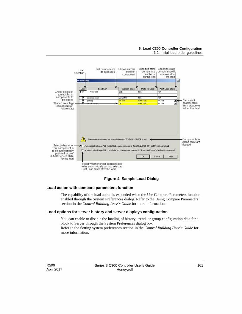
6. Load C300 Controller Configuration 6.2. Initial load order guidelines
R500 April 2017
Series 8 C300 Controller User's Guide Honeywell
161
Figure 4 Sample Load Dialog
Load action with compare parameters function
The capability of the load action is expanded when the Use Compare Parameters function
enabled through the System Preferences dialog. Refer to the Using Compare Parameters
section in the Control Building User’s Guide for more information.
Load options for server history and server displays configuration
You can enable or disable the loading of history, trend, or group configuration data for a
block to Server through the System Preferences dialog box.
Refer to the Setting system preferences section in the Control Building User’s Guide for
more information.
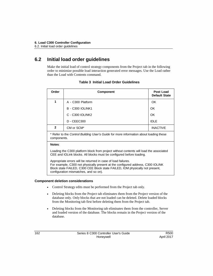
162 Series 8 C300 Controller User's Guide Honeywell
R500 April 2017
6. Load C300 Controller Configuration 6.2. Initial load order guidelines
6.2 Initial load order guidelines
Make the initial load of control strategy components from the Project tab in the following order to minimize possible load interaction generated error messages. Use the Load rather
than the Load with Contents command.
Table 3 Initial Load Order Guidelines
Order Component Post Load Default State
1 A - C300 Platform
B - C300 IOLINK1
C - C300 IOLINK2
D - CEEC300
OK
OK
OK
IDLE
2 CM or SCM* INACTIVE
* Refer to the Control Building User’s Guide for more information about loading these
components.
Notes:
Loading the C300 platform block from project without contents will load the associated CEE and IOLink blocks. All blocks must be configured before loading.
Appropriate errors will be returned in case of load failures.
For example, C300 not physically present at the configured address, C300 IOLINK Block state FAILED, C300 CEE Block state FAILED, IOM physically not present, configuration mismatches, and so on).
Component deletion considerations
Control Strategy edits must be performed from the Project tab only.
Deleting blocks from the Project tab eliminates them from the Project version of the
database only. Only blocks that are not loaded can be deleted. Delete loaded blocks from the Monitoring tab first before deleting them from the Project tab.
Deleting blocks from the Monitoring tab eliminates them from the controller, Server and loaded version of the database. The blocks remain in the Project version of the
database.
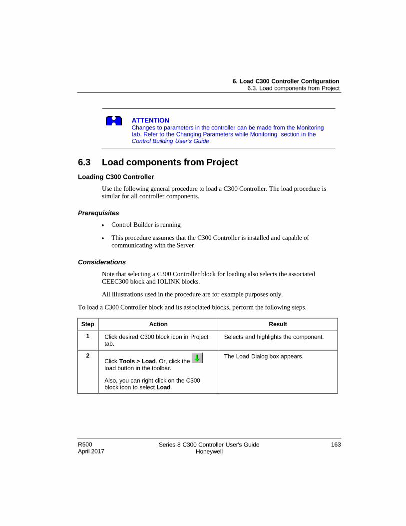
6. Load C300 Controller Configuration 6.3. Load components from Project
R500 April 2017
Series 8 C300 Controller User's Guide Honeywell
163
ATTENTION Changes to parameters in the controller can be made from the Monitoring tab. Refer to the Changing Parameters while Monitoring section in the Control Building User’s Guide.
6.3 Load components from Project
Loading C300 Controller
Use the following general procedure to load a C300 Controller. The load procedure is similar for all controller components.
Prerequisites
Control Builder is running
This procedure assumes that the C300 Controller is installed and capable of
communicating with the Server.
Considerations
Note that selecting a C300 Controller block for loading also selects the associated CEEC300 block and IOLINK blocks.
All illustrations used in the procedure are for example purposes only.
To load a C300 Controller block and its associated blocks, perform the following steps.
Step Action Result
1 Click desired C300 block icon in Project tab.
Selects and highlights the component.
2 Click Tools > Load. Or, click the
load button in the toolbar.
Also, you can right click on the C300 block icon to select Load.
The Load Dialog box appears.
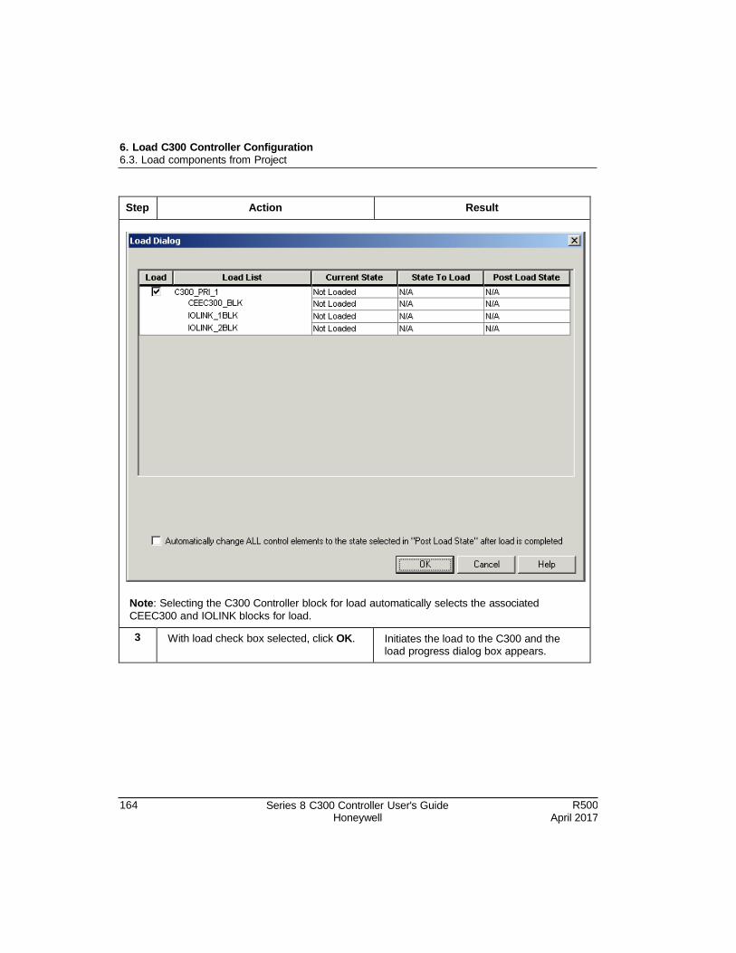
164 Series 8 C300 Controller User's Guide Honeywell
R500 April 2017
6. Load C300 Controller Configuration 6.3. Load components from Project
Step Action Result
Note: Selecting the C300 Controller block for load automatically selects the associated
CEEC300 and IOLINK blocks for load.
3 With load check box selected, click OK. Initiates the load to the C300 and the load progress dialog box appears.
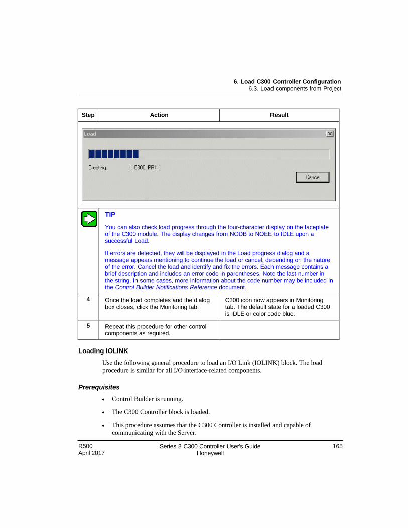
R500 April 2017
Series 8 C300 Controller User's Guide Honeywell
165
6. Load C300 Controller Configuration 6.3. Load components from Project
Step Action Result
TIP
You can also check load progress through the four-character display on the faceplate of the C300 module. The display changes from NODB to NOEE to IDLE upon a successful Load.
If errors are detected, they will be displayed in the Load progress dialog and a message appears mentioning to continue the load or cancel, depending on the nature of the error. Cancel the load and identify and fix the errors. Each message contains a brief description and includes an error code in parentheses. Note the last number in the string. In some cases, more information about the code number may be included in the Control Builder Notifications Reference document.
4 Once the load completes and the dialog box closes, click the Monitoring tab.
C300 icon now appears in Monitoring tab. The default state for a loaded C300 is IDLE or color code blue.
5 Repeat this procedure for other control components as required.
Loading IOLINK
Use the following general procedure to load an I/O Link (IOLINK) block. The load
procedure is similar for all I/O interface-related components.
Prerequisites
Control Builder is running.
The C300 Controller block is loaded.
This procedure assumes that the C300 Controller is installed and capable of
communicating with the Server.
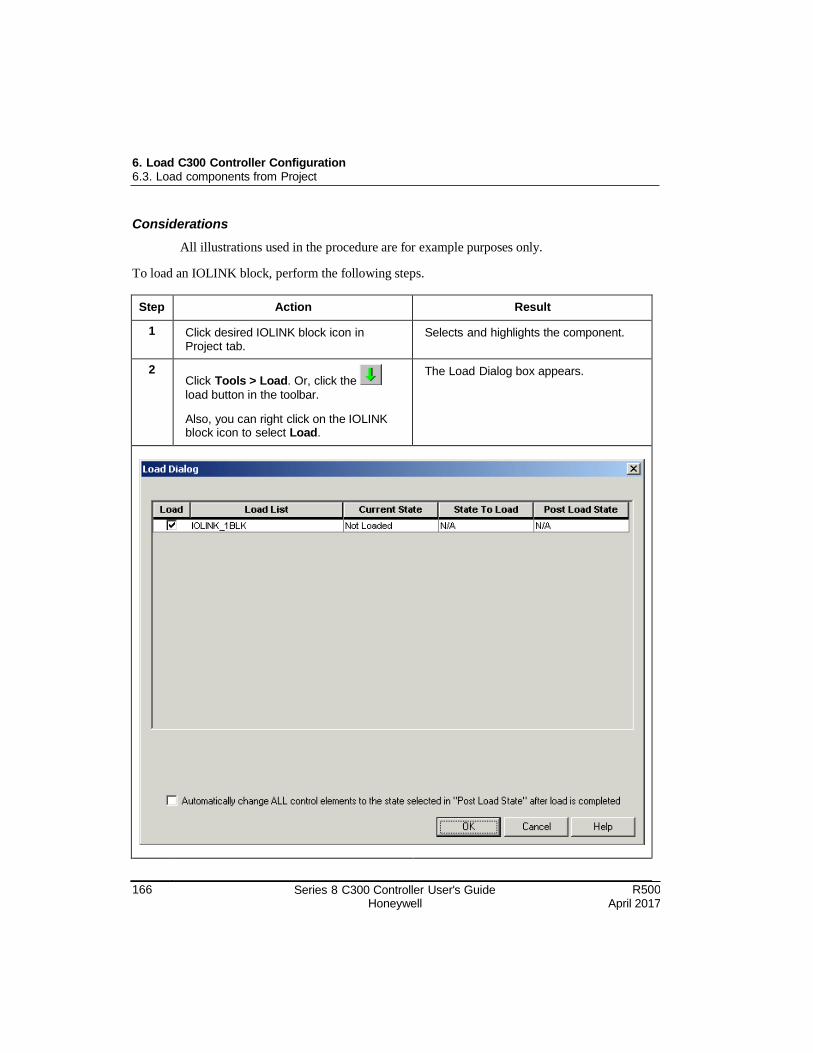
166 Series 8 C300 Controller User's Guide Honeywell
R500 April 2017
6. Load C300 Controller Configuration 6.3. Load components from Project
Considerations
All illustrations used in the procedure are for example purposes only.
To load an IOLINK block, perform the following steps.
Step Action Result
1 Click desired IOLINK block icon in Project tab.
Selects and highlights the component.
2 Click Tools > Load. Or, click the
load button in the toolbar.
Also, you can right click on the IOLINK block icon to select Load.
The Load Dialog box appears.
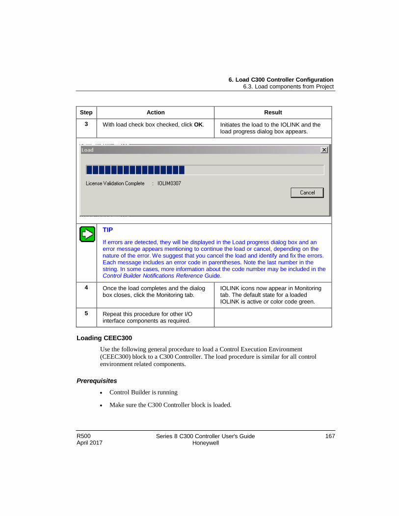
R500 April 2017
Series 8 C300 Controller User's Guide Honeywell
167
6. Load C300 Controller Configuration 6.3. Load components from Project
Step Action Result
3 With load check box checked, click OK. Initiates the load to the IOLINK and the load progress dialog box appears.
TIP
If errors are detected, they will be displayed in the Load progress dialog box and an error message appears mentioning to continue the load or cancel, depending on the nature of the error. We suggest that you cancel the load and identify and fix the errors. Each message includes an error code in parentheses. Note the last number in the string. In some cases, more information about the code number may be included in the Control Builder Notifications Reference Guide.
4 Once the load completes and the dialog box closes, click the Monitoring tab.
IOLINK icons now appear in Monitoring tab. The default state for a loaded IOLINK is active or color code green.
5 Repeat this procedure for other I/O interface components as required.
Loading CEEC300
Use the following general procedure to load a Control Execution Environment
(CEEC300) block to a C300 Controller. The load procedure is similar for all control environment related components.
Prerequisites
Control Builder is running
Make sure the C300 Controller block is loaded.
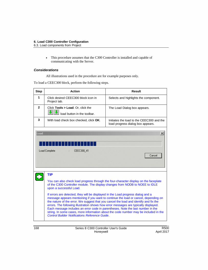
168 Series 8 C300 Controller User's Guide Honeywell
R500 April 2017
6. Load C300 Controller Configuration 6.3. Load components from Project
This procedure assumes that the C300 Controller is installed and capable of
communicating with the Server.
Considerations
All illustrations used in the procedure are for example purposes only.
To load a CEEC300 block, perform the following steps.
Step Action Result
1 Click desired CEEC300 block icon in Project tab.
Selects and highlights the component.
2 Click Tools > Load. Or, click the
load button in the toolbar.
The Load Dialog box appears.
3 With load check box checked, click OK. Initiates the load to the CEEC300 and the load progress dialog box appears.
TIP
You can also check load progress through the four-character display on the faceplate of the C300 Controller module. The display changes from NODB to NOEE to IDLE upon a successful Load.
If errors are detected, they will be displayed in the Load progress dialog and a message appears mentioning if you want to continue the load or cancel, depending on the nature of the error. We suggest that you cancel the load and identify and fix the errors. The following illustration shows how error messages are typically displayed. Each message includes an error code in parentheses. Note the last number in the string. In some cases, more information about the code number may be included in the Control Builder Notifications Reference Guide.
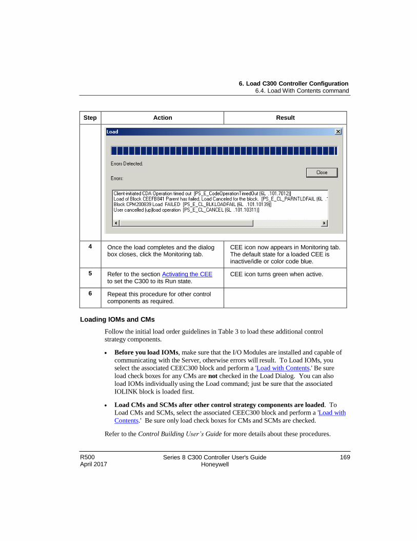
R500 April 2017
Series 8 C300 Controller User's Guide Honeywell
169
6. Load C300 Controller Configuration 6.4. Load With Contents command
Step Action Result
4 Once the load completes and the dialog box closes, click the Monitoring tab.
CEE icon now appears in Monitoring tab. The default state for a loaded CEE is inactive/idle or color code blue.
5 Refer to the section Activating the CEE to set the C300 to its Run state.
CEE icon turns green when active.
6 Repeat this procedure for other control components as required.
Loading IOMs and CMs
Follow the initial load order guidelines in Table 3 to load these additional control strategy components.
Before you load IOMs, make sure that the I/O Modules are installed and capable of
communicating with the Server, otherwise errors will result. To Load IOMs, you
select the associated CEEC300 block and perform a 'Load with Contents.' Be sure
load check boxes for any CMs are not checked in the Load Dialog. You can also
load IOMs individually using the Load command; just be sure that the associated
IOLINK block is loaded first.
Load CMs and SCMs after other control strategy components are loaded. To
Load CMs and SCMs, select the associated CEEC300 block and perform a 'Load with
Contents.' Be sure only load check boxes for CMs and SCMs are checked.
Refer to the Control Building User’s Guide for more details about these procedures.
6. Load C300 Controller Configuration 6.4. Load With Contents command
170 Series 8 C300 Controller User's Guide Honeywell
R500 April 2017
6.4 Load With Contents command
When you choose Tools > Load with Contents from the Tools menu, the Load Dialog
box shows the selected component and any objects, (IOMs, CMs, and so on.) that are
contained by the selected component. For example, when a CEEC300 block is selected
for loading, the Load Dialog will list all the objects assigned to (or contained by) that
CEE in the dialog window. You can then select (or deselect) the objects that you want to
load.
6.5 Reloading components from project
Reload of component configuration may be necessary especially when you make changes
to the component or function block configuration, or after you replace a failed field
device, I/O module or controller. You can use the applicable previous load procedure to
re-load data to components from the Project or Monitor tab. It is good idea to invoke the
following commands through the Controller menu after a reload operation.
Upload (perform first), and then
Update to Project
Restrictions and conditions for reloading operations
Re-loading parameter data to certain function blocks may incur some restrictions or
conditions with other related blocks. The following table lists conditions to consider
when re-loading previously loaded blocks.
Block to be Re-Loaded
Conditions or Restrictions
Series 8 IOMs
Channel blocks that are assigned and have not been previously loaded, will not be loaded.
CM The C300/CEE, IOLINK and IOMs whose channels are assigned to the CM must be previously loaded.
The CM reload operation loads the CM block and any assigned IO Channel blocks to the associated CEE.
CM reload fails if any of the following errors are encountered:
The I/O Channel's associated IOM block has not been previously loaded.
The CEE block is not present and loaded.
The C300 block is not present and loaded.
R500 April 2017
Series 8 C300 Controller User's Guide Honeywell
171
6. Load C300 Controller Configuration 6.5. Reloading components from project
Block to be Re-Loaded
Conditions or Restrictions
The CM is ACTIVE.
IOLINK The C300 Block must be present and previously loaded.
The state of previously loaded IOMs must be IDLE.
IOLINK block configuration parameters are re-loaded along with configuration data for previously loaded IOM Blocks.
Re-load fails and is cancelled if the C300 is not loaded, or the state of at least one previously loaded IOM is in RUN.
CEE The C300 Block must be present and previously loaded.
The state of the CEE must be IDLE.
C300 with Contents
The following blocks are re-loaded unless they are de-selected in the Load dialog box.
C300 Block
IOLINK Block with Contents for IOLINK 1
IOLINK Block with Contents for IOLINK 2
CEE Block with Contents
NOTE:
The configuration data of any previously loaded IOMs and CMs is not reloaded. You must reload any desired IOMs and CMs.
6. Load C300 Controller Configuration 6.6. Upload to the Monitoring database
172 Series 8 C300 Controller User's Guide Honeywell
R500 April 2017
6.6 Upload to the Monitoring database
The upload operation will upload data for the selected objects from the controller to the
Monitoring Engineering Repository Database (ERDB). Upload of data for the selected
objects from the server to the ERDB also can be performed.
Usually, after performing an upload to the database, you should also update the data to
Project so that both the Monitoring and the Project databases agree.
Refer to the Using Upload Command section in the Control Building User’s Guide for
procedures to upload component data.
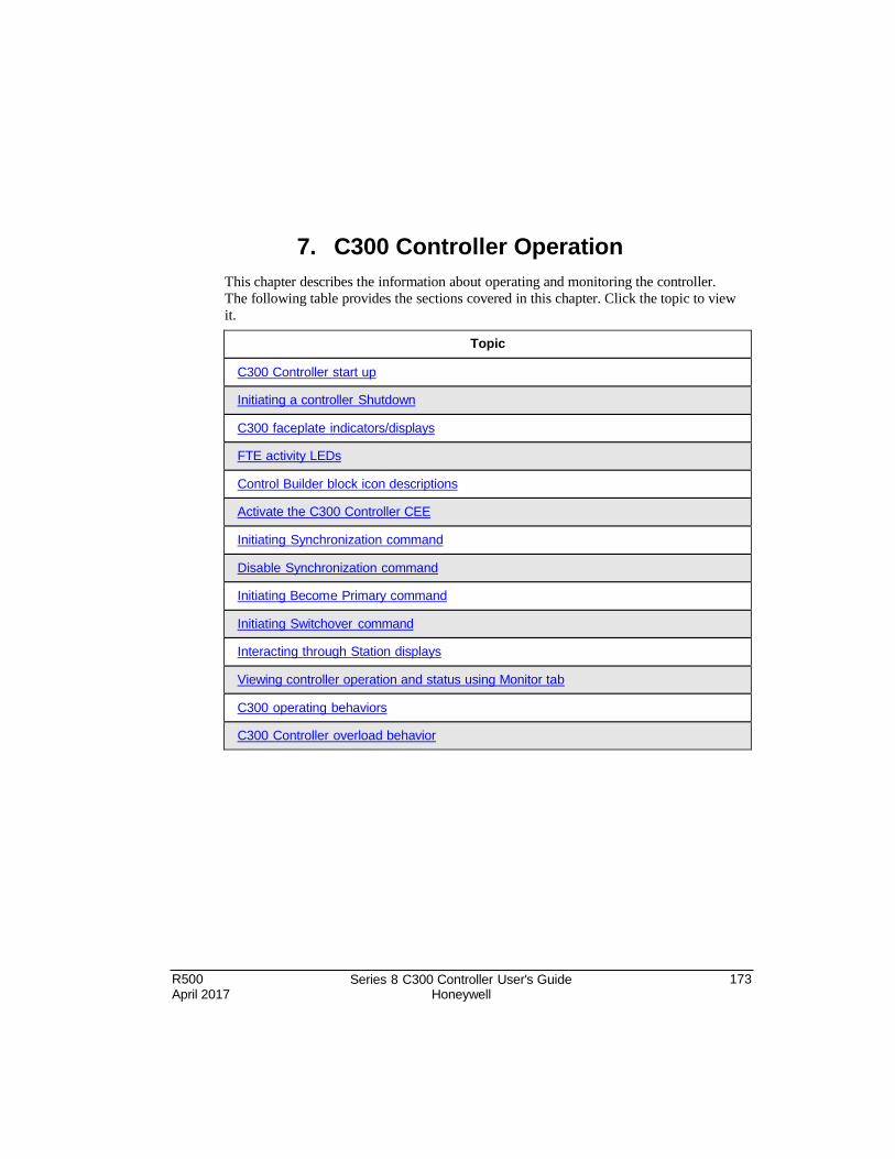
R500 April 2017
Series 8 C300 Controller User's Guide Honeywell
173
7. C300 Controller Operation
This chapter describes the information about operating and monitoring the controller.
The following table provides the sections covered in this chapter. Click the topic to view
it.
Topic
C300 Controller start up
Initiating a controller Shutdown
C300 faceplate indicators/displays
FTE activity LEDs
Control Builder block icon descriptions
Activate the C300 Controller CEE
Initiating Synchronization command
Disable Synchronization command
Initiating Becom e Primary command
Initiating Switchover command
Interacting through Station displays
Viewing controller operation and status using Monitor tab
C300 operating behaviors
C300 Controller overload behavior
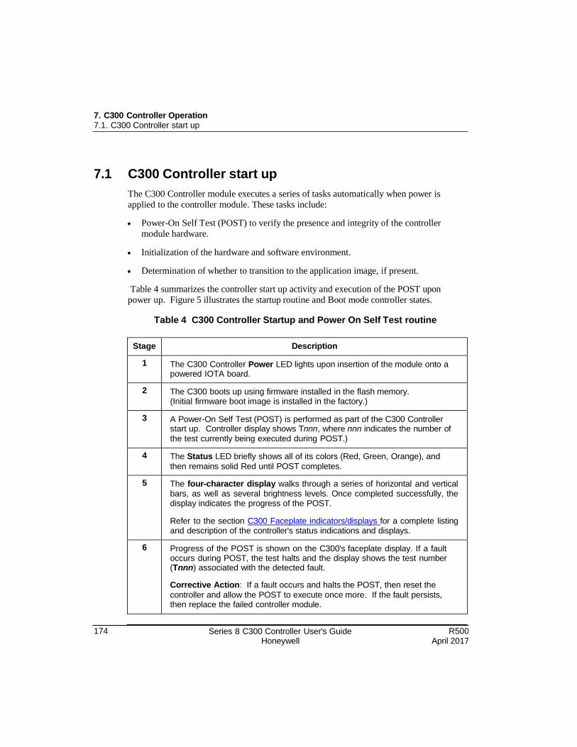
7. C300 Controller Operation 7.1. C300 Controller start up
174 Series 8 C300 Controller User's Guide Honeywell
R500 April 2017
7.1 C300 Controller start up
The C300 Controller module executes a series of tasks automatically when power is
applied to the controller module. These tasks include:
Power-On Self Test (POST) to verify the presence and integrity of the controller
module hardware.
Initialization of the hardware and software environment.
Determination of whether to transition to the application image, if present.
Table 4 summarizes the controller start up activity and execution of the POST upon
power up. Figure 5 illustrates the startup routine and Boot mode controller states.
Table 4 C300 Controller Startup and Power On Self Test routine
Stage Description
1 The C300 Controller Power LED lights upon insertion of the module onto a powered IOTA board.
2 The C300 boots up using firmware installed in the flash memory. (Initial firmware boot image is installed in the factory.)
3 A Power-On Self Test (POST) is performed as part of the C300 Controller start up. Controller display shows Tnnn, where nnn indicates the number of the test currently being executed during POST.)
4 The Status LED briefly shows all of its colors (Red, Green, Orange), and
then remains solid Red until POST completes.
5 The four-character display walks through a series of horizontal and vertical bars, as well as several brightness levels. Once completed successfully, the display indicates the progress of the POST.
Refer to the section C300 Faceplate indicators/displays for a complete listing and description of the controller's status indications and displays.
6 Progress of the POST is shown on the C300's faceplate display. If a fault occurs during POST, the test halts and the display shows the test number (Tnnn) associated with the detected fault.
Corrective Action: If a fault occurs and halts the POST, then reset the
controller and allow the POST to execute once more. If the fault persists, then replace the failed controller module.
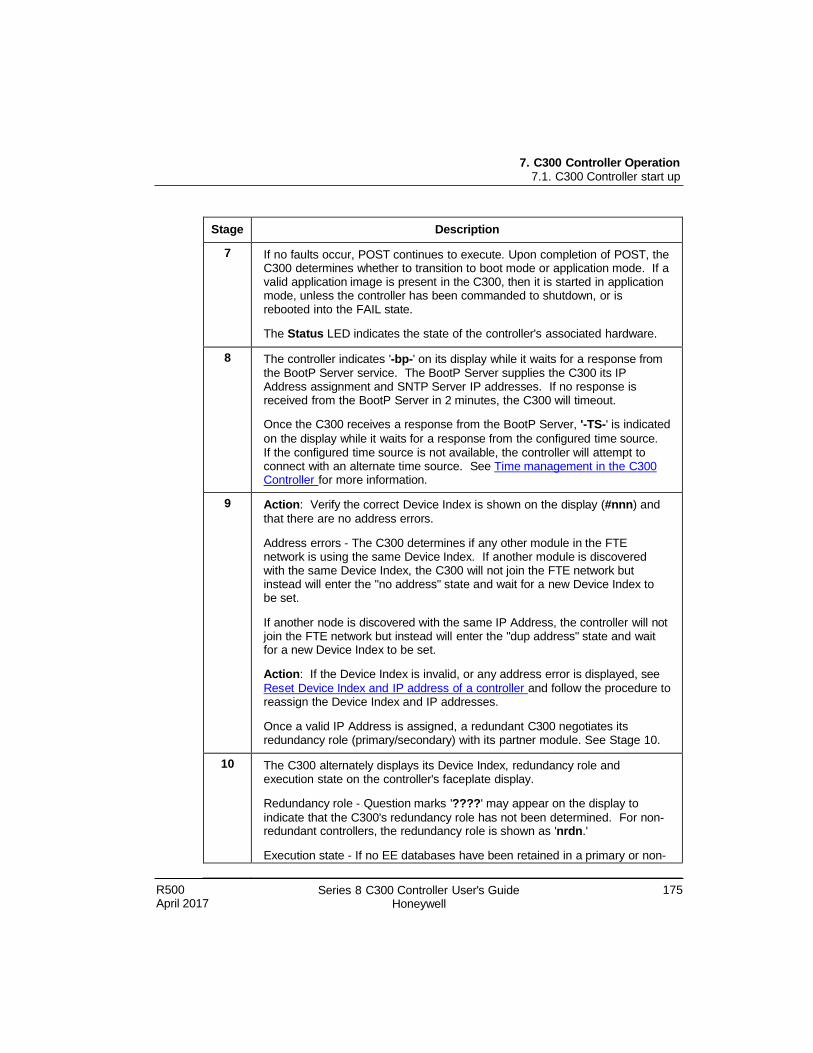
7. C300 Controller Operation 7.1. C300 Controller start up
R500 April 2017
Series 8 C300 Controller User's Guide Honeywell
175
Stage Description
7 If no faults occur, POST continues to execute. Upon completion of POST, the C300 determines whether to transition to boot mode or application mode. If a valid application image is present in the C300, then it is started in application mode, unless the controller has been commanded to shutdown, or is rebooted into the FAIL state.
The Status LED indicates the state of the controller's associated hardware.
8 The controller indicates '-bp-' on its display while it waits for a response from the BootP Server service. The BootP Server supplies the C300 its IP Address assignment and SNTP Server IP addresses. If no response is received from the BootP Server in 2 minutes, the C300 will timeout.
Once the C300 receives a response from the BootP Server, '-TS-' is indicated
on the display while it waits for a response from the configured time source. If the configured time source is not available, the controller will attempt to connect with an alternate time source. See Time management in the C300 Controller for more information.
9 Action: Verify the correct Device Index is shown on the display (#nnn) and
that there are no address errors.
Address errors - The C300 determines if any other module in the FTE network is using the same Device Index. If another module is discovered with the same Device Index, the C300 will not join the FTE network but instead will enter the "no address" state and wait for a new Device Index to be set.
If another node is discovered with the same IP Address, the controller will not join the FTE network but instead will enter the "dup address" state and wait for a new Device Index to be set.
Action: If the Device Index is invalid, or any address error is displayed, see
Res et Device Index and IP address of a controller and follow the procedure to reassign the Device Index and IP addresses.
Once a valid IP Address is assigned, a redundant C300 negotiates its redundancy role (primary/secondary) with its partner module. See Stage 10.
10 The C300 alternately displays its Device Index, redundancy role and execution state on the controller's faceplate display.
Redundancy role - Question marks '????' may appear on the display to
indicate that the C300's redundancy role has not been determined. For non- redundant controllers, the redundancy role is shown as 'nrdn.'
Execution state - If no EE databases have been retained in a primary or non-
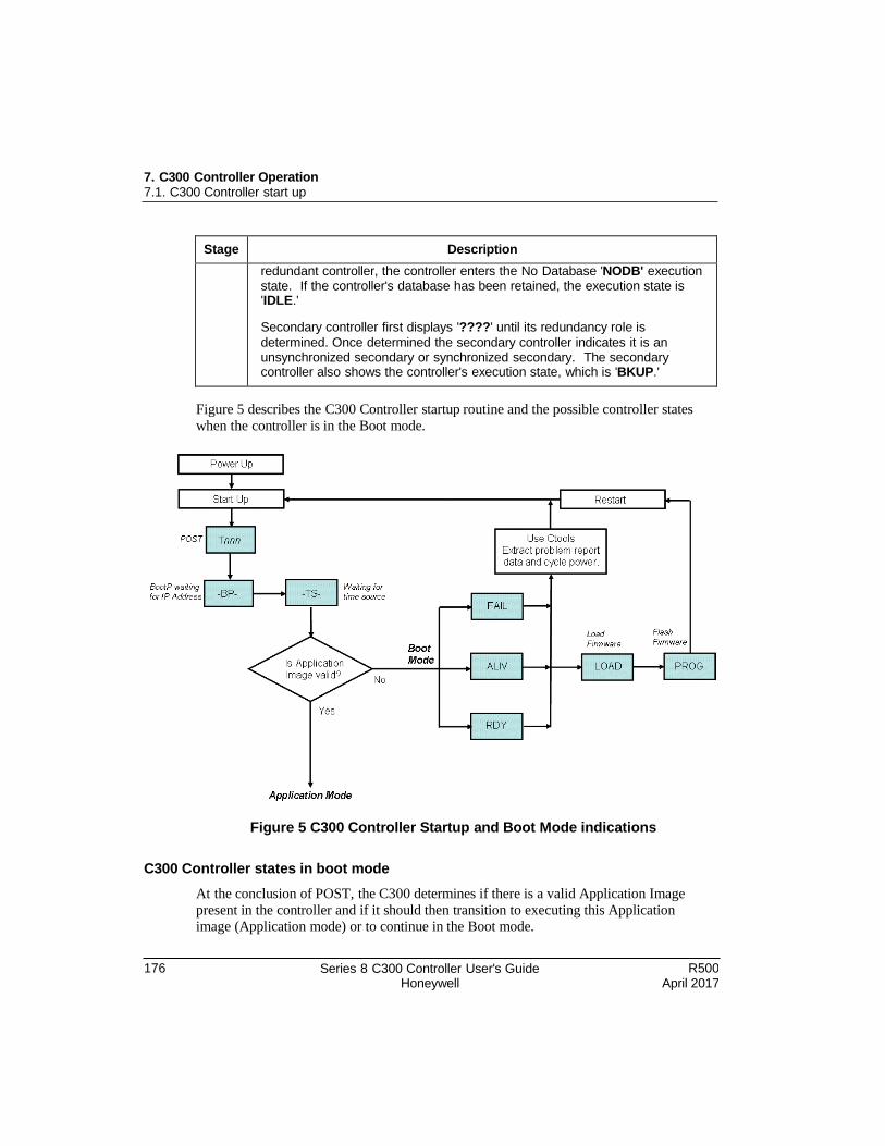
7. C300 Controller Operation 7.1. C300 Controller start up
176 Series 8 C300 Controller User's Guide Honeywell
R500 April 2017
Stage Description
redundant controller, the controller enters the No Database 'NODB' execution state. If the controller's database has been retained, the execution state is 'IDLE.'
Secondary controller first displays '????' until its redundancy role is
determined. Once determined the secondary controller indicates it is an unsynchronized secondary or synchronized secondary. The secondary controller also shows the controller's execution state, which is 'BKUP.'
Figure 5 describes the C300 Controller startup routine and the possible controller states
when the controller is in the Boot mode.
Figure 5 C300 Controller Startup and Boot Mode indications
C300 Controller states in boot mode
At the conclusion of POST, the C300 determines if there is a valid Application Image
present in the controller and if it should then transition to executing this Application image (Application mode) or to continue in the Boot mode.
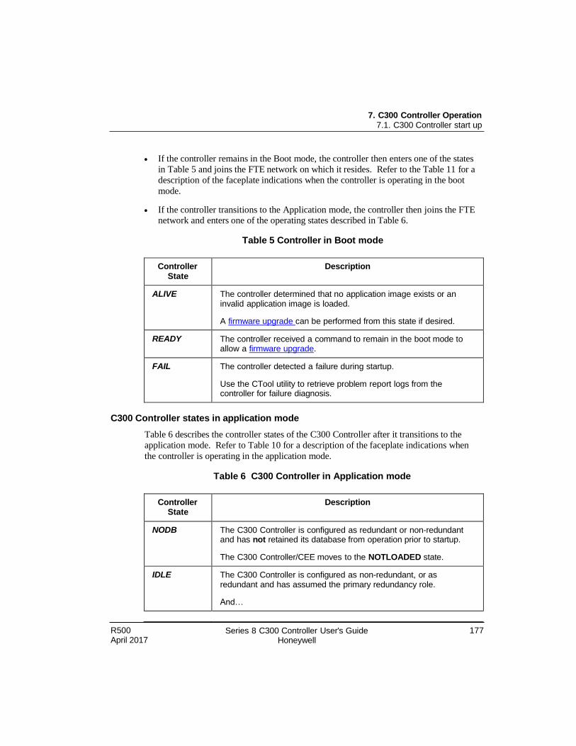
7. C300 Controller Operation 7.1. C300 Controller start up
R500 April 2017
Series 8 C300 Controller User's Guide Honeywell
177
If the controller remains in the Boot mode, the controller then enters one of the states
in Table 5 and joins the FTE network on which it resides. Refer to the Table 11 for a
description of the faceplate indications when the controller is operating in the boot
mode.
If the controller transitions to the Application mode, the controller then joins the FTE network and enters one of the operating states described in Table 6.
Table 5 Controller in Boot mode
Controller State
Description
ALIVE The controller determined that no application image exists or an invalid application image is loaded.
A firmware upgrade can be performed from this state if desired.
READY The controller received a command to remain in the boot mode to allow a firmware upgrade.
FAIL The controller detected a failure during startup.
Use the CTool utility to retrieve problem report logs from the controller for failure diagnosis.
C300 Controller states in application mode
Table 6 describes the controller states of the C300 Controller after it transitions to the
application mode. Refer to Table 10 for a description of the faceplate indications when
the controller is operating in the application mode.
Table 6 C300 Controller in Application mode
Controller State
Description
NODB The C300 Controller is configured as redundant or non-redundant and has not retained its database from operation prior to startup.
The C300 Controller/CEE moves to the NOTLOADED state.
IDLE The C300 Controller is configured as non-redundant, or as redundant and has assumed the primary redundancy role.
And…
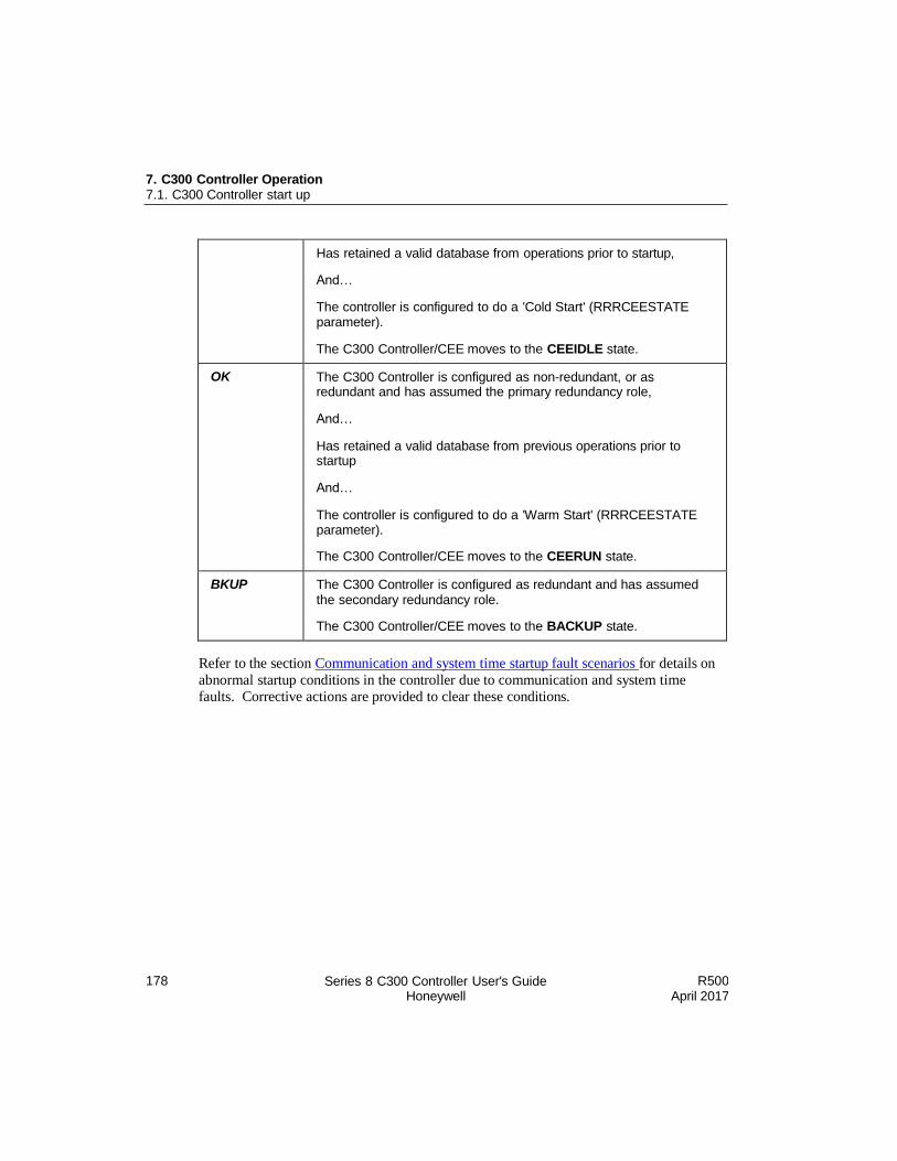
7. C300 Controller Operation 7.1. C300 Controller start up
178 Series 8 C300 Controller User's Guide Honeywell
R500 April 2017
Has retained a valid database from operations prior to startup,
And…
The controller is configured to do a 'Cold Start' (RRRCEESTATE parameter).
The C300 Controller/CEE moves to the CEEIDLE state.
OK The C300 Controller is configured as non-redundant, or as redundant and has assumed the primary redundancy role,
And…
Has retained a valid database from previous operations prior to startup
And…
The controller is configured to do a 'Warm Start' (RRRCEESTATE parameter).
The C300 Controller/CEE moves to the CEERUN state.
BKUP The C300 Controller is configured as redundant and has assumed the secondary redundancy role.
The C300 Controller/CEE moves to the BACKUP state.
Refer to the section Communication and system time startup fault scenarios for details on
abnormal startup conditions in the controller due to communication and system time faults. Corrective actions are provided to clear these conditions.
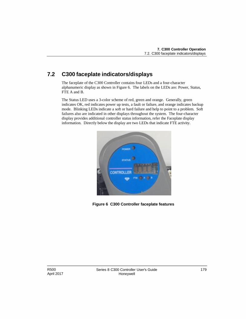
R500 April 2017
Series 8 C300 Controller User's Guide Honeywell
179
7. C300 Controller Operation 7.2. C300 faceplate indicators/displays
7.2 C300 faceplate indicators/displays
The faceplate of the C300 Controller contains four LEDs and a four-character
alphanumeric display as shown in Figure 6. The labels on the LEDs are: Power, Status,
FTE A and B.
The Status LED uses a 3-color scheme of red, green and orange. Generally, green
indicates OK, red indicates power up tests, a fault or failure, and orange indicates backup
mode. Blinking LEDs indicate a soft or hard failure and help to point to a problem. Soft
failures also are indicated in other displays throughout the system. The four-character
display provides additional controller status information, refer the Faceplate display
information. Directly below the display are two LEDs that indicate FTE activity.
Figure 6 C300 Controller faceplate features
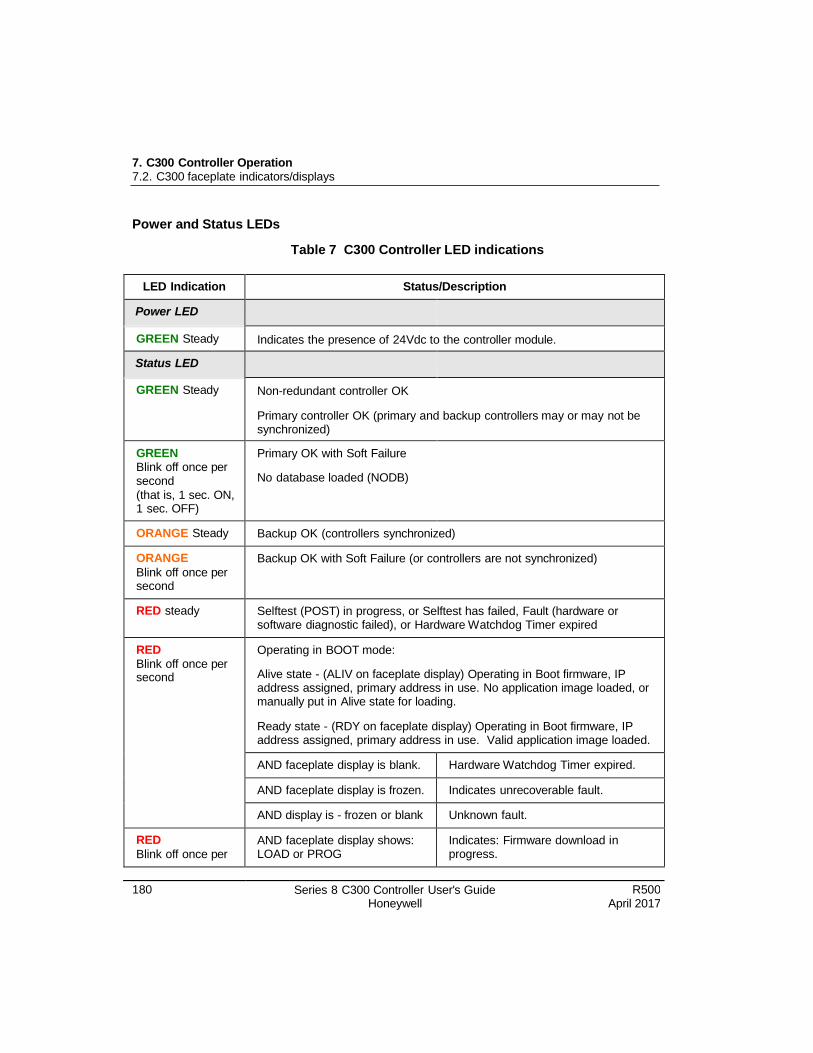
7. C300 Controller Operation 7.2. C300 faceplate indicators/displays
180 Series 8 C300 Controller User's Guide Honeywell
R500 April 2017
Power and Status LEDs
Table 7 C300 Controller LED indications
LED Indication Status/Description
Power LED
GREEN Steady Indicates the presence of 24Vdc to the controller module.
Status LED
GREEN Steady Non-redundant controller OK
Primary controller OK (primary and backup controllers may or may not be synchronized)
GREEN Blink off once per second
(that is, 1 sec. ON, 1 sec. OFF)
Primary OK with Soft Failure
No database loaded (NODB)
ORANGE Steady Backup OK (controllers synchronized)
ORANGE
Blink off once per second
Backup OK with Soft Failure (or controllers are not synchronized)
RED steady Selftest (POST) in progress, or Selftest has failed, Fault (hardware or software diagnostic failed), or Hardware Watchdog Timer expired
RED
Blink off once per second
Operating in BOOT mode:
Alive state - (ALIV on faceplate display) Operating in Boot firmware, IP address assigned, primary address in use. No application image loaded, or manually put in Alive state for loading.
Ready state - (RDY on faceplate display) Operating in Boot firmware, IP address assigned, primary address in use. Valid application image loaded.
AND faceplate display is blank. Hardware Watchdog Timer expired.
AND faceplate display is frozen. Indicates unrecoverable fault.
AND display is - frozen or blank Unknown fault.
RED
Blink off once per AND faceplate display shows: LOAD or PROG
Indicates: Firmware download in progress.
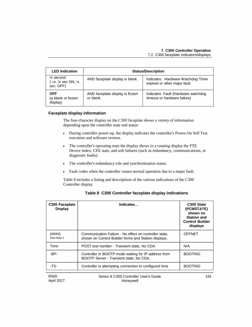
7. C300 Controller Operation 7.2. C300 faceplate indicators/displays
R500 April 2017
Series 8 C300 Controller User's Guide Honeywell
181
LED Indication Status/Description
¼ second ( i.e. ¼ sec ON, ¼ sec. OFF)
AND faceplate display is blank. Indicates: Hardware Watchdog Timer expired or other major fault.
OFF
(a blank or frozen display)
AND faceplate display is frozen or blank.
Indicates: Fault (Hardware watchdog timeout or hardware failure)
Faceplate display information
The four-character display on the C300 faceplate shows a variety of information
depending upon the controller state and status:
During controller power-up, the display indicates the controller's Power-On Self Test
execution and software version.
The controller's operating state the display shows in a rotating display the FTE
Device Index, CEE state, and soft failures (such as redundancy, communications, or
diagnostic faults).
The controller's redundancy role and synchronization status.
Fault codes when the controller ceases normal operation due to a major fault.
Table 8 includes a listing and descriptions of the various indications of the C300
Controller display.
Table 8 C300 Controller faceplate display indications
C300 Faceplate Display
Indicates… C300 State
(PCMSTATE) shown on
Station and Control Builder
displays
(####) See Note 1
Communication Failure - No effect on controller state, shown on Control Builder forms and Station displays.
OFFNET
Tnnn POST test number - Transient state, No CDA. N/A
-BP- Controller in BOOTP mode waiting for IP address from BOOTP Server - Transient state, No CDA.
BOOTING
-TS- Controller is attempting connection to configured time BOOTING
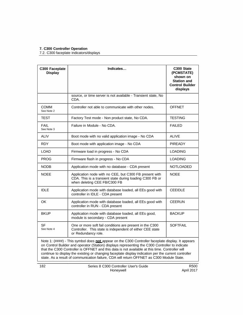
7. C300 Controller Operation 7.2. C300 faceplate indicators/displays
182 Series 8 C300 Controller User's Guide Honeywell
R500 April 2017
C300 Faceplate Display
Indicates… C300 State (PCMSTATE)
shown on Station and
Control Builder displays
source, or time server is not available - Transient state, No CDA.
COMM See Note 2
Controller not able to communicate with other nodes. OFFNET
TEST Factory Test mode - Non product state, No CDA. TESTING
FAIL See Note 3
Failure in Module - No CDA. FAILED
ALIV Boot mode with no valid application image - No CDA ALIVE
RDY Boot mode with application image - No CDA PIREADY
LOAD Firmware load in progress - No CDA LOADING
PROG Firmware flash in progress - No CDA LOADING
NODB Application mode with no database - CDA present NOTLOADED
NOEE Application node with no CEE, but C300 FB present with CDA. This is a transient state during loading C300 FB or when deleting CEE FB/C300 FB
NOEE
IDLE Application mode with database loaded, all EEs good with controller in IDLE - CDA present
CEEIDLE
OK Application mode with database loaded, all EEs good with controller in RUN - CDA present
CEERUN
BKUP Application mode with database loaded, all EEs good, module is secondary - CDA present
BACKUP
SF See Note 4
One or more soft fail conditions are present in the C300 Controller. This state is independent of either CEE state or Redundancy role.
SOFTFAIL
Note 1: (####) - This symbol does not appear on the C300 Controller faceplate display. It appears
on Control Builder and operator (Station) displays representing the C300 Controller to indicate that the C300 Controller is OFFNET and this data is not available at this time. Controller will continue to display the existing or changing faceplate display indication per the current controller state. As a result of communication failure, CDA will return OFFNET as C300 Module State.
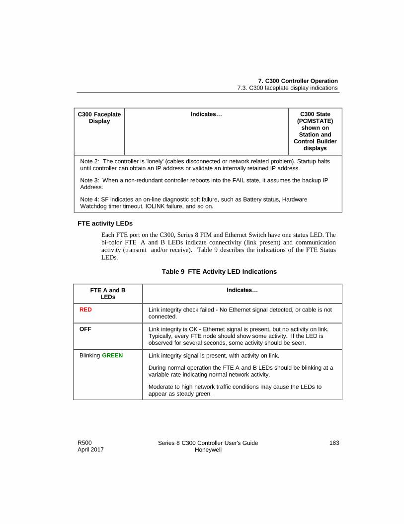
R500 April 2017
Series 8 C300 Controller User's Guide Honeywell
183
7. C300 Controller Operation 7.3. C300 faceplate display indications
C300 Faceplate Display
Indicates… C300 State (PCMSTATE)
shown on Station and
Control Builder displays
Note 2: The controller is 'lonely' (cables disconnected or network related problem). Startup halts until controller can obtain an IP address or validate an internally retained IP address.
Note 3: When a non-redundant controller reboots into the FAIL state, it assumes the backup IP Address.
Note 4: SF indicates an on-line diagnostic soft failure, such as Battery status, Hardware Watchdog timer timeout, IOLINK failure, and so on.
FTE activity LEDs
Each FTE port on the C300, Series 8 FIM and Ethernet Switch have one status LED. The
bi-color FTE A and B LEDs indicate connectivity (link present) and communication activity (transmit and/or receive). Table 9 describes the indications of the FTE Status
LEDs.
Table 9 FTE Activity LED Indications
FTE A and B LEDs
Indicates…
RED Link integrity check failed - No Ethernet signal detected, or cable is not connected.
OFF Link integrity is OK - Ethernet signal is present, but no activity on link. Typically, every FTE node should show some activity. If the LED is observed for several seconds, some activity should be seen.
Blinking GREEN Link integrity signal is present, with activity on link.
During normal operation the FTE A and B LEDs should be blinking at a variable rate indicating normal network activity.
Moderate to high network traffic conditions may cause the LEDs to appear as steady green.

184 Series 8 C300 Controller User's Guide Honeywell
R500 April 2017
7. C300 Controller Operation 7.3. C300 faceplate display indications
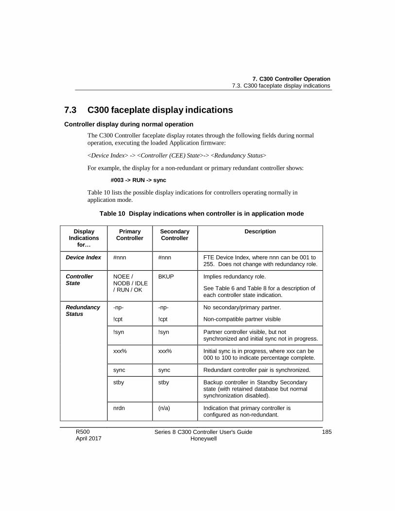
R500 April 2017
Series 8 C300 Controller User's Guide Honeywell
185
7. C300 Controller Operation 7.3. C300 faceplate display indications
7.3 C300 faceplate display indications
Controller display during normal operation
The C300 Controller faceplate display rotates through the following fields during normal
operation, executing the loaded Application firmware:
<Device Index> -> <Controller (CEE) State>-> <Redundancy Status>
For example, the display for a non-redundant or primary redundant controller shows:
#003 -> RUN -> sync
Table 10 lists the possible display indications for controllers operating normally in
application mode.
Table 10 Display indications when controller is in application mode
Display Indications
for…
Primary Controller
Secondary Controller
Description
Device Index #nnn #nnn FTE Device Index, where nnn can be 001 to 255. Does not change with redundancy role.
Controller State
NOEE /
NODB / IDLE / RUN / OK
BKUP Implies redundancy role.
See Table 6 and Table 8 for a description of each controller state indication.
Redundancy Status
-np- -np- No secondary/primary partner.
!cpt !cpt Non-compatible partner visible
!syn !syn Partner controller visible, but not synchronized and initial sync not in progress.
xxx% xxx% Initial sync is in progress, where xxx can be 000 to 100 to indicate percentage complete.
sync sync Redundant controller pair is synchronized.
stby stby Backup controller in Standby Secondary state (with retained database but normal synchronization disabled).
nrdn (n/a) Indication that primary controller is configured as non-redundant.
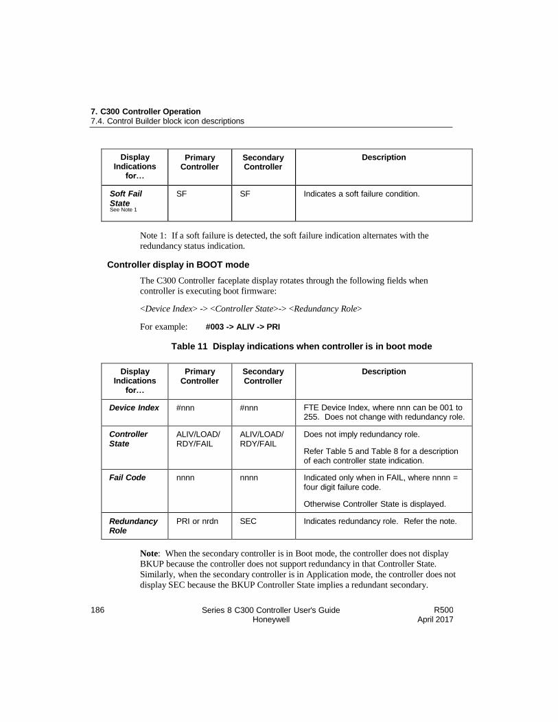
186 Series 8 C300 Controller User's Guide Honeywell
R500 April 2017
7. C300 Controller Operation 7.4. Control Builder block icon descriptions
Display Indications
for…
Primary Controller
Secondary Controller
Description
Soft Fail
State See Note 1
SF SF Indicates a soft failure condition.
Note 1: If a soft failure is detected, the soft failure indication alternates with the
redundancy status indication.
Controller display in BOOT mode
The C300 Controller faceplate display rotates through the following fields when
controller is executing boot firmware:
<Device Index> -> <Controller State>-> <Redundancy Role>
For example: #003 -> ALIV -> PRI
Table 11 Display indications when controller is in boot mode
Display Indications
for…
Primary Controller
Secondary Controller
Description
Device Index #nnn #nnn FTE Device Index, where nnn can be 001 to 255. Does not change with redundancy role.
Controller State
ALIV/LOAD/ RDY/FAIL
ALIV/LOAD/ RDY/FAIL
Does not imply redundancy role.
Refer Table 5 and Table 8 for a description of each controller state indication.
Fail Code nnnn nnnn Indicated only when in FAIL, where nnnn = four digit failure code.
Otherwise Controller State is displayed.
Redundancy Role
PRI or nrdn SEC Indicates redundancy role. Refer the note.
Note: When the secondary controller is in Boot mode, the controller does not display
BKUP because the controller does not support redundancy in that Controller State.
Similarly, when the secondary controller is in Application mode, the controller does not
display SEC because the BKUP Controller State implies a redundant secondary.
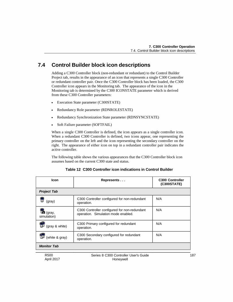
R500 April 2017
Series 8 C300 Controller User's Guide Honeywell
187
7. C300 Controller Operation 7.4. Control Builder block icon descriptions
7.4 Control Builder block icon descriptions
Adding a C300 Controller block (non-redundant or redundant) to the Control Builder
Project tab, results in the appearance of an icon that represents a single C300 Controller
or redundant controller pair. Once the C300 Controller block has been loaded, the C300
Controller icon appears in the Monitoring tab. The appearance of the icon in the
Monitoring tab is determined by the C300 ICONSTATE parameter which is derived
from these C300 Controller parameters:
Execution State parameter (C300STATE)
Redundancy Role parameter (RDNROLESTATE)
Redundancy Synchronization State parameter (RDNSYNCSTATE)
Soft Failure parameter (SOFTFAIL)
When a single C300 Controller is defined, the icon appears as a single controller icon.
When a redundant C300 Controller is defined, two icons appear, one representing the
primary controller on the left and the icon representing the secondary controller on the
right. The appearance of either icon on top in a redundant controller pair indicates the
active controller.
The following table shows the various appearances that the C300 Controller block icon
assumes based on the current C300 state and status.
Table 12 C300 Controller icon indications in Control Builder
Icon Represents . . . C300 Controller (C300STATE)
Project Tab
(gray) C300 Controller configured for non-redundant operation.
N/A
(gray, simulation)
C300 Controller configured for non-redundant operation. Simulation mode enabled.
N/A
(gray & white) C300 Primary configured for redundant operation.
N/A
(white & gray) C300 Secondary configured for redundant operation.
N/A
Monitor Tab
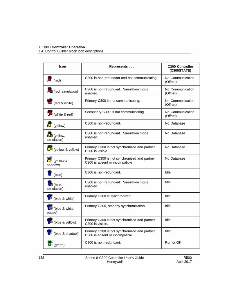
188 Series 8 C300 Controller User's Guide Honeywell
R500 April 2017
7. C300 Controller Operation 7.4. Control Builder block icon descriptions
Icon Represents . . . C300 Controller (C300STATE)
(red) C300 is non-redundant and not communicating. No Communication
(Offnet)
(red, simulation) C300 is non-redundant. Simulation mode enabled.
No Communication (Offnet)
(red & white) Primary C300 is not communicating. No Communication
(Offnet)
(white & red) Secondary C300 is not communicating. No Communication
(Offnet)
(yellow) C300 is non-redundant. No Database
(yellow, simulation)
C300 is non-redundant. Simulation mode enabled.
No Database
(yellow & yellow) Primary C300 is not synchronized and partner C300 is visible
No Database
(yellow & shadow)
Primary C300 is not synchronized and partner C300 is absent or incompatible
No Database
(blue) C300 is non-redundant. Idle
(blue, simulation)
C300 is non-redundant. Simulation mode enabled.
Idle
(blue & white) Primary C300 is synchronized. Idle
(blue & white, pause)
Primary C300, standby synchronization. Idle
(blue & yellow) Primary C300 is not synchronized and partner C300 is visible.
Idle
(blue & shadow) Primary C300 is not synchronized and partner C300 is absent or incompatible.
Idle
(green) C300 is non-redundant. Run or OK
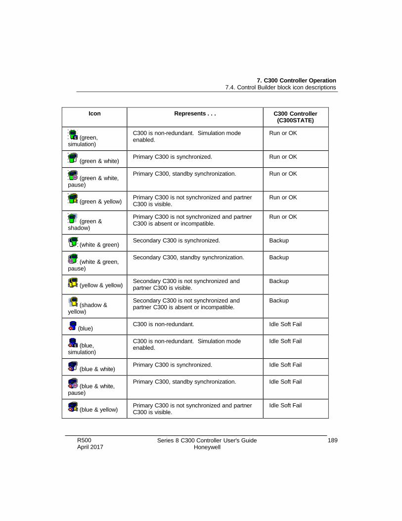
R500 April 2017
Series 8 C300 Controller User's Guide Honeywell
189
7. C300 Controller Operation 7.4. Control Builder block icon descriptions
Icon Represents . . . C300 Controller (C300STATE)
(green, simulation)
C300 is non-redundant. Simulation mode enabled.
Run or OK
(green & white) Primary C300 is synchronized. Run or OK
(green & white, pause)
Primary C300, standby synchronization. Run or OK
(green & yellow) Primary C300 is not synchronized and partner C300 is visible.
Run or OK
(green & shadow)
Primary C300 is not synchronized and partner C300 is absent or incompatible.
Run or OK
(white & green) Secondary C300 is synchronized. Backup
(white & green, pause)
Secondary C300, standby synchronization. Backup
(yellow & yellow) Secondary C300 is not synchronized and partner C300 is visible.
Backup
(shadow & yellow)
Secondary C300 is not synchronized and partner C300 is absent or incompatible.
Backup
(blue) C300 is non-redundant. Idle Soft Fail
(blue, simulation)
C300 is non-redundant. Simulation mode enabled.
Idle Soft Fail
(blue & white) Primary C300 is synchronized. Idle Soft Fail
(blue & white, pause)
Primary C300, standby synchronization. Idle Soft Fail
(blue & yellow) Primary C300 is not synchronized and partner C300 is visible.
Idle Soft Fail
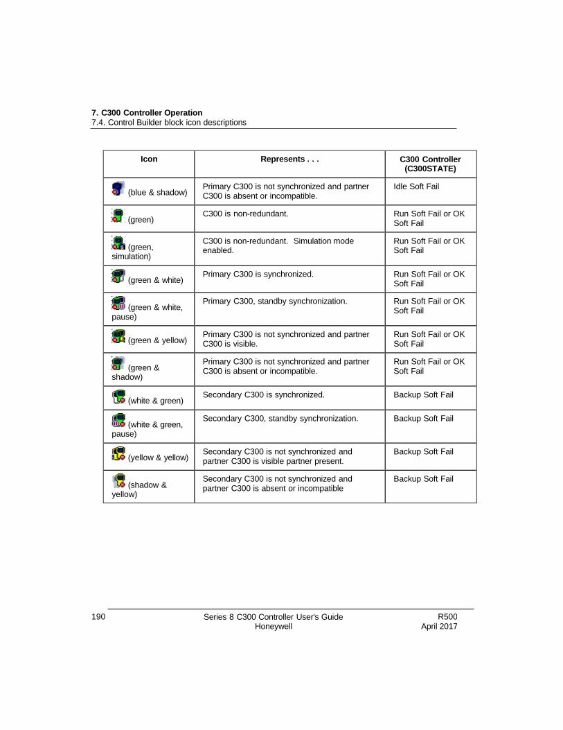
190 Series 8 C300 Controller User's Guide Honeywell
R500 April 2017
7. C300 Controller Operation 7.4. Control Builder block icon descriptions
Icon Represents . . . C300 Controller (C300STATE)
(blue & shadow) Primary C300 is not synchronized and partner C300 is absent or incompatible.
Idle Soft Fail
(green) C300 is non-redundant. Run Soft Fail or OK
Soft Fail
(green, simulation)
C300 is non-redundant. Simulation mode enabled.
Run Soft Fail or OK Soft Fail
(green & white) Primary C300 is synchronized. Run Soft Fail or OK
Soft Fail
(green & white, pause)
Primary C300, standby synchronization. Run Soft Fail or OK Soft Fail
(green & yellow) Primary C300 is not synchronized and partner C300 is visible.
Run Soft Fail or OK Soft Fail
(green & shadow)
Primary C300 is not synchronized and partner C300 is absent or incompatible.
Run Soft Fail or OK Soft Fail
(white & green) Secondary C300 is synchronized. Backup Soft Fail
(white & green, pause)
Secondary C300, standby synchronization. Backup Soft Fail
(yellow & yellow) Secondary C300 is not synchronized and partner C300 is visible partner present.
Backup Soft Fail
(shadow & yellow)
Secondary C300 is not synchronized and partner C300 is absent or incompatible
Backup Soft Fail
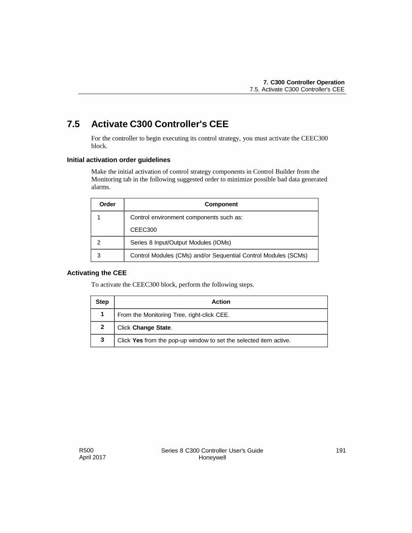
7. C300 Controller Operation 7.5. Activate C300 Controller's CEE
R500 April 2017
Series 8 C300 Controller User's Guide Honeywell
191
7.5 Activate C300 Controller's CEE
For the controller to begin executing its control strategy, you must activate the CEEC300
block.
Initial activation order guidelines
Make the initial activation of control strategy components in Control Builder from the
Monitoring tab in the following suggested order to minimize possible bad data generated
alarms.
Order Component
1 Control environment components such as:
CEEC300
2 Series 8 Input/Output Modules (IOMs)
3 Control Modules (CMs) and/or Sequential Control Modules (SCMs)
Activating the CEE
To activate the CEEC300 block, perform the following steps.
Step Action
1 From the Monitoring Tree, right-click CEE.
2 Click Change State.
3 Click Yes from the pop-up window to set the selected item active.
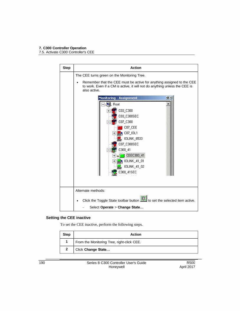
7. C300 Controller Operation 7.5. Activate C300 Controller's CEE
190 Series 8 C300 Controller User's Guide Honeywell
R500 April 2017
Step Action
The CEE turns green on the Monitoring Tree.
Remember that the CEE must be active for anything assigned to the CEE to work. Even if a CM is active, it will not do anything unless the CEE is also active.
Alternate methods:
Click the Toggle State toolbar button to set the selected item active.
Select Operate > Change State…
Setting the CEE inactive
To set the CEE inactive, perform the following steps.
Step Action
1 From the Monitoring Tree, right-click CEE.
2 Click Change State…

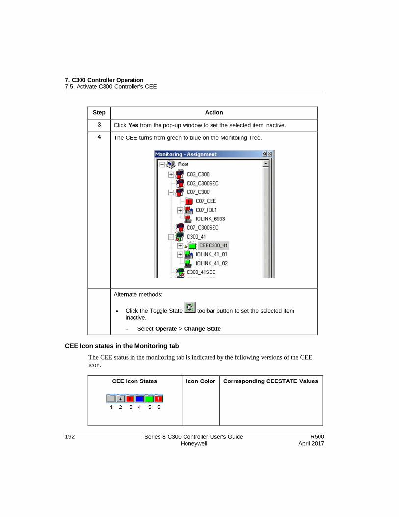
7. C300 Controller Operation 7.5. Activate C300 Controller's CEE
192 Series 8 C300 Controller User's Guide Honeywell
R500 April 2017
Step Action
3 Click Yes from the pop-up window to set the selected item inactive.
4 The CEE turns from green to blue on the Monitoring Tree.
Alternate methods:
Click the Toggle State toolbar button to set the selected item inactive.
Select Operate > Change State
CEE Icon states in the Monitoring tab
The CEE status in the monitoring tab is indicated by the following versions of the CEE
icon.
CEE Icon States
Icon Color Corresponding CEESTATE Values
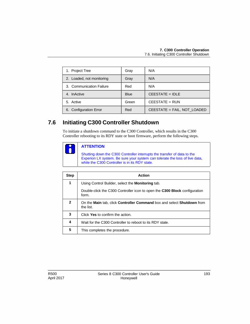
R500 April 2017
Series 8 C300 Controller User's Guide Honeywell
193
7. C300 Controller Operation 7.6. Initiating C300 Controller Shutdown
ATTENTION
Shutting down the C300 Controller interrupts the transfer of data to the Experion LX system. Be sure your system can tolerate the loss of live data, while the C300 Controller is in its RDY state.
1. Project Tree Gray N/A
2. Loaded, not monitoring Gray N/A
3. Communication Failure Red N/A
4. InActive Blue CEESTATE = IDLE
5. Active Green CEESTATE = RUN
6. Configuration Error Red CEESTATE = FAIL, NOT_LOADED
7.6 Initiating C300 Controller Shutdown
To initiate a shutdown command to the C300 Controller, which results in the C300
Controller rebooting to its RDY state or boot firmware, perform the following steps.
Step Action
1 Using Control Builder, select the Monitoring tab.
Double-click the C300 Controller icon to open the C300 Block configuration
form.
2 On the Main tab, click Controller Command box and select Shutdown from
the list.
3 Click Yes to confirm the action.
4 Wait for the C300 Controller to reboot to its RDY state.
5 This completes the procedure.
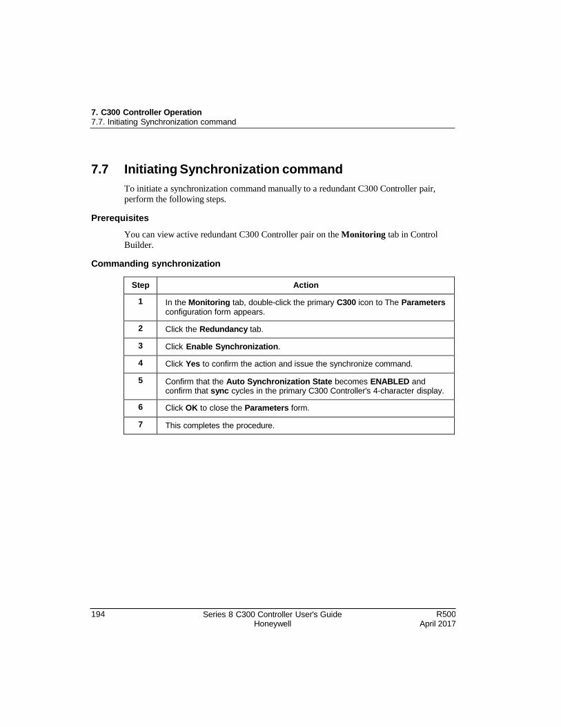
194 Series 8 C300 Controller User's Guide Honeywell
R500 April 2017
7. C300 Controller Operation 7.7. Initiating Synchronization command
7.7 Initiating Synchronization command
To initiate a synchronization command manually to a redundant C300 Controller pair,
perform the following steps.
Prerequisites
You can view active redundant C300 Controller pair on the Monitoring tab in Control
Builder.
Commanding synchronization
Step Action
1 In the Monitoring tab, double-click the primary C300 icon to The Parameters configuration form appears.
2 Click the Redundancy tab.
3 Click Enable Synchronization.
4 Click Yes to confirm the action and issue the synchronize command.
5 Confirm that the Auto Synchronization State becomes ENABLED and confirm that sync cycles in the primary C300 Controller's 4-character display.
6 Click OK to close the Parameters form.
7 This completes the procedure.
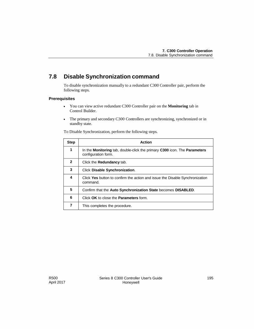
R500 April 2017
Series 8 C300 Controller User's Guide Honeywell
195
7. C300 Controller Operation 7.8. Disable Synchronization command
7.8 Disable Synchronization command
To disable synchronization manually to a redundant C300 Controller pair, perform the
following steps.
Prerequisites
You can view active redundant C300 Controller pair on the Monitoring tab in
Control Builder.
The primary and secondary C300 Controllers are synchronizing, synchronized or in standby state.
To Disable Synchronization, perform the following steps.
Step Action
1 In the Monitoring tab, double-click the primary C300 icon. The Parameters configuration form.
2 Click the Redundancy tab.
3 Click Disable Synchronization.
4 Click Yes button to confirm the action and issue the Disable Synchronization
command.
5 Confirm that the Auto Synchronization State becomes DISABLED.
6 Click OK to close the Parameters form.
7 This completes the procedure.
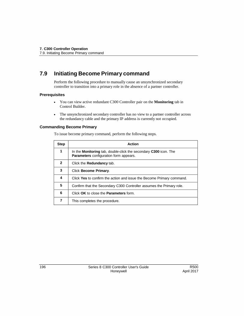
196 Series 8 C300 Controller User's Guide Honeywell
R500 April 2017
7. C300 Controller Operation 7.9. Initiating Become Primary command
7.9 Initiating Become Primary command
Perform the following procedure to manually cause an unsynchronized secondary
controller to transition into a primary role in the absence of a partner controller.
Prerequisites
You can view active redundant C300 Controller pair on the Monitoring tab in
Control Builder.
The unsynchronized secondary controller has no view to a partner controller across the redundancy cable and the primary IP address is currently not occupied.
Commanding Become Primary
To issue become primary command, perform the following steps.
Step Action
1 In the Monitoring tab, double-click the secondary C300 icon. The Parameters configuration form appears.
2 Click the Redundancy tab.
3 Click Become Primary.
4 Click Yes to confirm the action and issue the Become Primary command.
5 Confirm that the Secondary C300 Controller assumes the Primary role.
6 Click OK to close the Parameters form.
7 This completes the procedure.
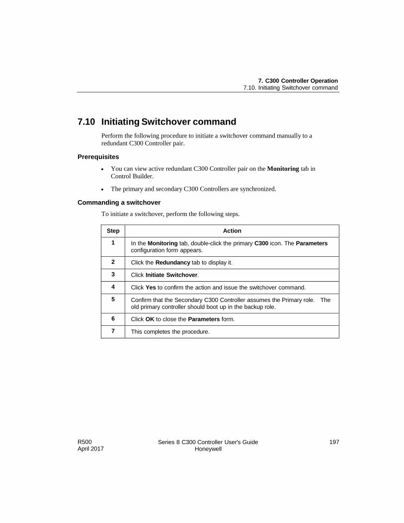
R500 April 2017
Series 8 C300 Controller User's Guide Honeywell
197
7. C300 Controller Operation 7.10. Initiating Switchover command
7.10 Initiating Switchover command
Perform the following procedure to initiate a switchover command manually to a
redundant C300 Controller pair.
Prerequisites
You can view active redundant C300 Controller pair on the Monitoring tab in
Control Builder.
The primary and secondary C300 Controllers are synchronized.
Commanding a switchover
To initiate a switchover, perform the following steps.
Step Action
1 In the Monitoring tab, double-click the primary C300 icon. The Parameters configuration form appears.
2 Click the Redundancy tab to display it.
3 Click Initiate Switchover.
4 Click Yes to confirm the action and issue the switchover command.
5 Confirm that the Secondary C300 Controller assumes the Primary role. The old primary controller should boot up in the backup role.
6 Click OK to close the Parameters form.
7 This completes the procedure.
198 Series 8 C300 Controller User's Guide Honeywell
R500 April 2017
7. C300 Controller Operation 7.11. Using Station displays
7.11 Using Station displays
Operation and status information as well as statistics for C300 Controllers can be
monitored through various displays located on Experion LX servers and stations. Some
of these displays are briefly described below. Refer to the Operator's Guide for more
information about system and detail displays in Station.
C300 Controller Point Detail displays
The Experion LX Server Station application includes pre-configured Detail displays for
the C300 Controller and function blocks. These displays are the default entries for the
Point Detail Display parameter on the Server Displays tab of the configuration form.
Once you establish communications with a C300 Controller you can begin monitoring
the status of any component that has been loaded as part of a control strategy to a C300
Controller with points registered in the Experion LX Server. The Detail displays let you
quickly view the component's current state, fault status and pertinent configuration data.
System Status Display
The System Status Display is part of the Alarm Management Displays in Station.
The C300 Controller is represented in the System Status Display using the same icon set
as is used in the Control Builder Monitor Tree.
Event and Alarm summary displays
Experion LX Station also provides Event and Alarm Summary displays that support
C300 Controller notifications and events. These displays are integrated with Experion
LX component data. Use the Event Summary to get a quick view of recent actions that
have taken place within the system.
Controller Detail displays
The Controller Status display provides a status of each controller and its type. Click on
the Controller name to call up the Controller's Detail display. This display shows
operating values and error statistics that indicate the 'health' of the controller.
FTE Status display
The C300 Controller is a single node on the FTE network. As one of the System Status
displays in Station, the FTE Status display provides status information for each node on
the associated network.
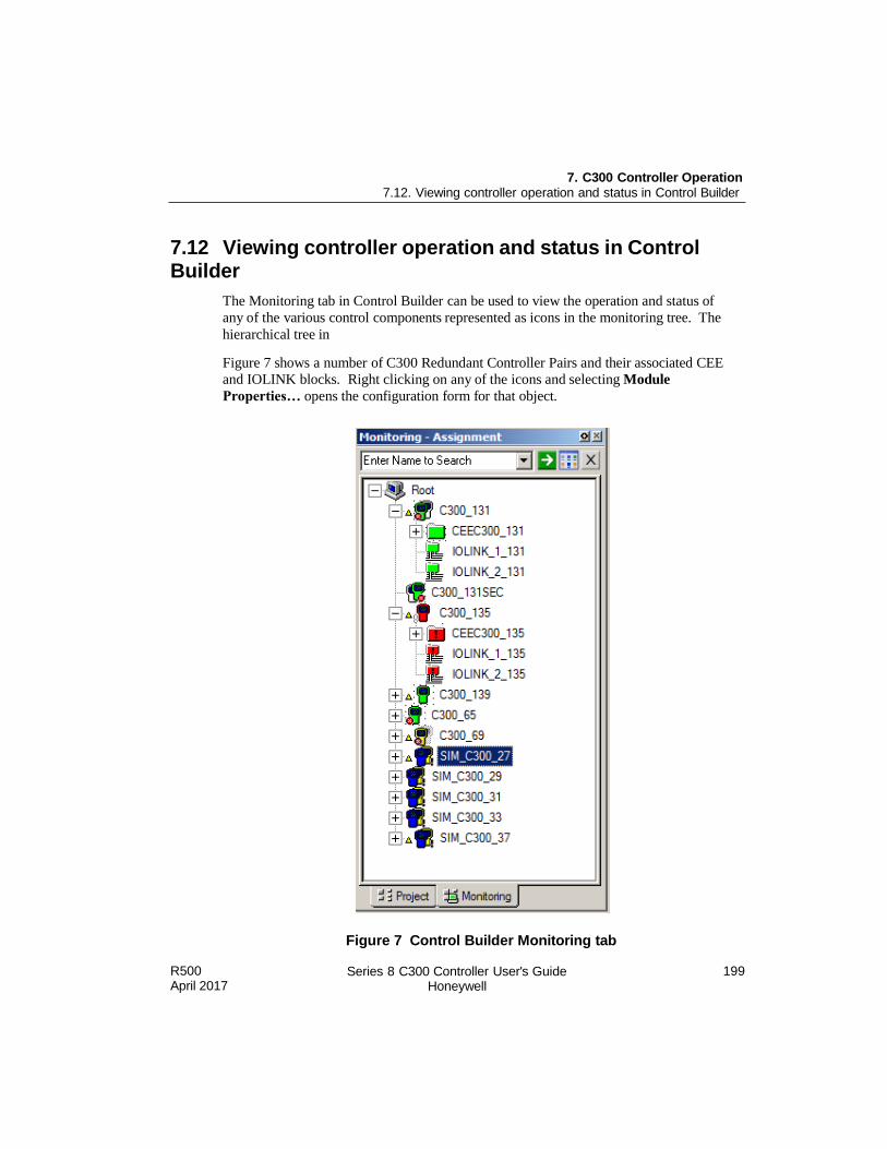
R500 April 2017
Series 8 C300 Controller User's Guide Honeywell
199
7. C300 Controller Operation 7.12. Viewing controller operation and status in Control Builder
7.12 Viewing controller operation and status in Control Builder
The Monitoring tab in Control Builder can be used to view the operation and status of
any of the various control components represented as icons in the monitoring tree. The
hierarchical tree in
Figure 7 shows a number of C300 Redundant Controller Pairs and their associated CEE
and IOLINK blocks. Right clicking on any of the icons and selecting Module
Properties… opens the configuration form for that object.
Figure 7 Control Builder Monitoring tab
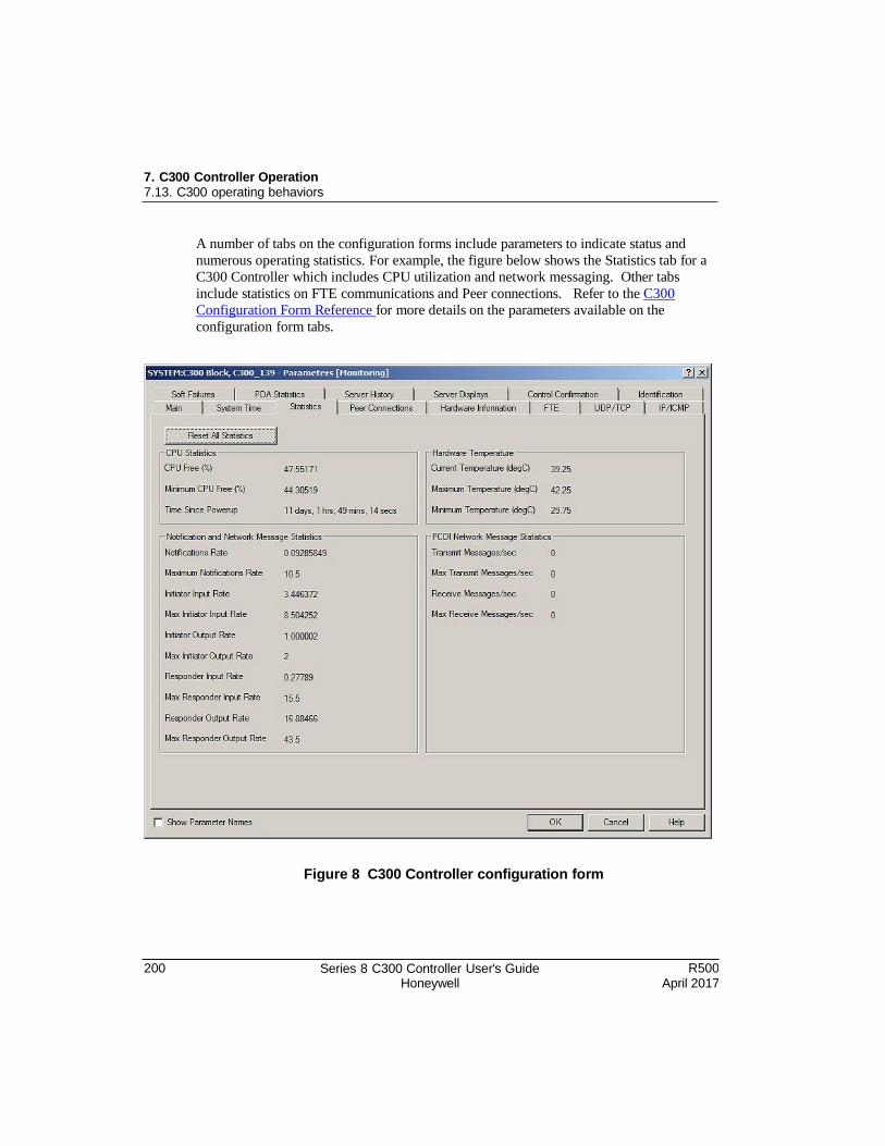
7. C300 Controller Operation 7.13. C300 operating behaviors
200 Series 8 C300 Controller User's Guide Honeywell
R500 April 2017
A number of tabs on the configuration forms include parameters to indicate status and
numerous operating statistics. For example, the figure below shows the Statistics tab for a
C300 Controller which includes CPU utilization and network messaging. Other tabs
include statistics on FTE communications and Peer connections. Refer to the C300
Configuration Form Reference for more details on the parameters available on the
configuration form tabs.
Figure 8 C300 Controller configuration form
R500 April 2017
Series 8 C300 Controller User's Guide Honeywell
201
7. C300 Controller Operation 7.13. C300 operating behaviors
7.13 C300 operating behaviors
This section describes some of the C300 Controller's features and operating behaviors
related to event and alarm reporting.
Time management in the C300 Controller
The C300 Controller requires a reliable and high quality time source to correlate events
from other devices in the system. Simple Network Time Protocol (SNTP), from a
dedicated Network Time Protocol (NTP) Server is the preferred time source for the
controller, although the controller can operate using other time sources, such as SNTP or
CDA from Experion LX Server.
The C300 synchronizes its local clock through NTP at startup and every minute. In the
absence of SNTP, the local clock is synchronized with CDA on first connection and every minute.
Refer to the Setting up time synchronization in the Supplementary Installation Tasks Guide for information on setting up a system time server.
Adjustments to time occur in the controller to maintain synchronization with the time
source. If the difference between the system time source and the controller's wall clock
time (WCT) is less than 5 minutes, then time is adjusted in increments. If the controller's
WCT differs by more than 5 minutes with the time source, controller time is set to match
the time source with an immediate correction. An information notification is generated
by the controller and sent to the events server.
Note that the controller’s WCT is lost during loss of power and cannot be restored in
RAM retention start scenario. Therefore, the controller will not have any information
regarding the WCT during the absence of Server. This affects the system planning and
controller usefulness. The time in the controller cannot be used reliably for control
applications.
Time synchronization between a primary and secondary C300 Controller is maintained
by the redundancy sub-system. The primary controller passes its WCT to the secondary
controller. Time adjustments are made to achieve time synchronization between the
redundant controller pair.
The C300 also maintains a Sequence Of Events (SOE) clock to synchronize to the system
time source (whenever one is available). Time adjustment occurs in a similar manner,
except that the SOE clock will be set to match the time source whenever a difference
between the source and the SOE clock exceeds 5 seconds.
Note that in the absence of an NTP time source, SOE event correlation is degraded across
a controller switchover. Events occurring before switchover are consistent, and events
7. C300 Controller Operation 7.13. C300 operating behaviors
202 Series 8 C300 Controller User's Guide Honeywell
R500 April 2017
occurring after switchover are consistent, but the timestamps of the two groups of
timestamps (before and after switchover) are degraded with respect to each other.
During normal operation the C300 Controller maintains a timeout on the current system
time source so that the controller can detect an interruption and switch to an alternative
time source. The controller will attempt periodically to re-establish a connection to a
better time source when it is not currently connected to its configured time source. If the
connection with the configured time source is lost, the controller will timeout after 90
seconds and will transition to use CDA - provided the controller remains connected to the
FTE network. The controller generates diagnostic and state notifications announcing the
change of the time source.
If the CDA time source becomes unavailable, the controller will continue to run and
execute control. The controller will use its internal Wall Clock Time as it time source
and will continue attempts to reconnect with its configured time source. The controller
generates diagnostic and state notifications announcing the change of the time source
Hardware Watchdog Timer
A Hardware Watchdog Timer is employed in conjunction with the Health Monitor and
the internal Memory Management Unit to ensure that a catastrophic failure which disrupts
the controller's internal instruction execution or timing results in the controller
achieving a fail-safe state. The timer is refreshed periodically during normal controller
operation. If a refresh does not occur within the required time interval, the controller
suspends control execution and is placed into a safe state. A hardware watchdog timeout
may cause the controller faceplate display to become blank and the Status LED will blink
red in ¼ second intervals. The controller will attempt to re-boot into the FAIL state.
A refresh of the watchdog timer later than expected in normal operation, but not late
enough to cause a timeout produces the soft failure condition: WDT Software Warning.
Critical Task Monitor
The Critical Task Monitor detects conditions for tasks executing within the controller
which are critical to proper control and view. Alarms and soft failures are generated when any of these tasks execute less frequently than expected.
Tasks critical to control
When a timeout occurs in the Critical Task Monitor for a task critical to performing
control, the controller asserts a hard failure, suspends normal operation and re-boots into
the FAIL state. If the controller is redundant and synchronized with the secondary
controller prior to the failure on the primary, a switchover occurs to allow the secondary
to assume control. If the controller is non-redundant or the controller is redundant but
was not synchronized with its secondary, the failed controller is placed into a fail safe
R500 April 2017
Series 8 C300 Controller User's Guide Honeywell
203
7. C300 Controller Operation 7.14. C300 Controller processing overload behavior
state. If capable, the controller will re-boot into the FAIL state. When a timeout of a
control-critical task occurs, the controller generates the appropriate alarms (Diagnostic
Alarm - Critical Task Watchdog Warning), but no other action is taken by the controller.
There is an exception to this behavior where a timeout occurs when the controller CPU is heavily loaded and the CPUFREE parameter indicates less than 5%. The controller does
not take any action and does not re-boot into a FAIL state.
Tasks critical to view
Tasks executing in the controller, which are critical to view, such as communication with
I/O, display or peer devices, may not execute as required due to excessive loading of the
CPU. The CPU overloading due to tasks other than executing control and result in a
sustained level of CPU Free at 0% (CPU usage is 100%) may cause a loss of view of the
controller.
When a timeout of a view-critical task occurs, the controller generates the appropriate
alarms (Diagnostic Alarm - Critical Task Watchdog Warning), but no other action is
taken by the controller.
7.14 C300 Controller processing overload behavior
The C300 Controller is able to handle controller processing overload conditions when the
controller is required to perform more work than it has time for. The execution of control
strategies or control processing usually demands the most resources in terms of processor
time and is the most likely cause of an overload condition in a controller, (although
other non-control processing causes can produce controller overloads). When
the C300 controller detects an overload, it will 'borrow' time from control execution by
suspending control processing in a defined and predictable manner. This allows the
controller to continue operation to provide control and maintain view and communication
under these conditions.
Controller operation is structured in terms of a 'base cycle' in which key processing tasks
are executed. An overload condition may occur when the controller is scheduled to
perform more tasks than can be completed within a base cycle. For example, a controller
is scheduled to execute more control processing tasks than is recommended, which may
include control, I/O and communications processing tasks. If the scheduled tasks cannot
be completed by the controller within the base cycle, a control overrun occurs.
Control overruns are reported as a diagnostic event in the C300CEE block as 'cycle
overruns', (CRCYCLEOVRN and LSCYCLEOVRN parameters). The controller
manages cycle overruns when the scheduled processing for a cycle does not finish by
85% of the ‘base cycle’ time in the following ways depending on the range of scheduled
processing time.
204 Series 8 C300 Controller User's Guide Honeywell
R500 April 2017
7. C300 Controller Operation 7.14. C300 Controller processing overload behavior
If the scheduled processing for a cycle is completed in more than 85% and less than
100% of the base cycle time, then cycle overrun will be logged and next cycle will be
skipped.
If the scheduled processing for a cycle is completed in more than 100% and less than 150% of the base cycle time, then unbudgeted tasks will be executed during the
remaining 50+ % time. Next cycle will continue scheduled processing.
If the scheduled processing for a cycle is completed in more than 150% of base cycle time next cycle will be skipped.
Cycle overruns in the controller result in that control degrades gracefully, in terms that
the latency in control loops increases. Also, a significant amount of processing time is
made available to the controller so that it can handle the backlog of tasks that result from
an overload.
Alarms and events are generated to alert operators to the cause of a controller overload so
that appropriate actions can be taken to remedy it.
Causes of controller overloading
Additional processing loads can be caused in many ways including, but not limited to:
Activation of additional CMs/SCMs/IOMs in the controller.
Load and activation of additional CMs/SCMs/IOMs to other controller.
Load and activation of additional CMs/SCMs to other controllers that impose added
peer-peer communication load on the controller of interest.
Call up of displays that collect data from the controller.
How to avoid controller overloading
Planning your control strategies will help to avoid overloading a C300 Controller.
Develop a performance model to determine whether or not a C300 Controller has the
resources to execute the planned strategy. Test the strategy before loading it to the
controller.
During operation acknowledge warning alarms associated with low values of 'CPU Free'
and overloads when control strategies are loaded incrementally to the controller. Take
appropriate steps to reduce CPU usage. Overloads also may occur when a large control
strategy is loaded at once, (such as a Checkpoint restore or a bulk load), rather than
incrementally.
The C300 block supports the following diagnostic alarms related to CPU Free:
R500 April 2017
Series 8 C300 Controller User's Guide Honeywell
205
7. C300 Controller Operation 7.14. C300 Controller processing overload behavior
CPU Free Low
Threshold defaults to 20% and is user configurable
Alarm is generated when CPU Free is less than the threshold.
CPU Free Low Low
Threshold is fixed at 10% and is not user configurable.
Alarm is generated when CPU Free is less than 10%.
Alarms and parameters that are associated with monitoring CPU use in the C300
Controller are CPUFREEAVG and CPUFREEMIN. These parameters are displayed on
the C300 Detail Display in Station and on the C300 properties form, (the Statistics tab of
the C300 block configuration form).
Parameters that measure the ability of the controller to execute loaded control strategies
are CPUCYCLEAVG and CRCYCLEOVRN. These and other related parameters are
displayed of the CPU Loading tab and the CPU Overruns tab of the CEEC300 block
configuration form.
Recovery from an overload
Recovery from a controller overload condition depends upon whether the overload is due
to a control processing (CEE Overrun - slipped cycle) or non-control processing (degraded or loss of view) overload condition.
ATTENTION When attempting recovery from an overload condition, you should determine the endpoint of this recovery process. Use these following guidelines:
The controller should operate in the steady state without persistent overload alarms of any type.
The controller should operate in the steady state without CPULMLOLO alarms.
The controller should operate in the steady state with an average CPUFREEAVG of at least 20%.
Control processing overloads indicated by CEE Cycle Overruns and 'control cycle slips' make enough processing time available so that adequate view of the controller is
maintained. Consider the following actions to lessen control processing overloads:
206 Series 8 C300 Controller User's Guide Honeywell
R500 April 2017
7. C300 Controller Operation 7.14. C300 Controller processing overload behavior
Change the execution period and/or phase of some selected Control Modules in order
to more evenly distribute control processing across all control cycles in the two (2)
second control macro-cycle.
If the action above does not lessen control processing overload, then delete some of the loaded control strategy. That is, inactivate and/or delete some number of Control
Modules (CMs). To perform this recovery process, first consider:
Which of the loaded CMs to delete from the C300 Controller in order to recover from the overloaded state.
Prepare for the selective loss of control that will result as individual CMs are placed in the Inactive state, and possibly deleted.
Then:
Begin by placing the least critical CMs in the Inactive state while monitoring
CPUFREE and the alarms that signaled the overload.
When the alarms indicating overload have 'returned-to-normal' and CPUFREE has
reached 5%, delete the CMs selected for deletion.
If a loss of view occurs due to non-control processing overload, then perform the
following actions:
Close displays requesting information from lost-view controller until view is restored.
If the loss of view is caused by an overload of display requests, it may be possible to
recover view by reducing the display request load to the controller.
If the C300 Controller is running as a redundant synchronized pair, Disable
Synchronization by clicking the 'Disable Synchronization' button on the secondary
C300 block properties form (if view exists to the secondary C300), or power off the
secondary controller. This will free up processor time that had been used to maintain
synchronization. The additional processor time may be sufficient to support
communication and view.
Shutdown controller and incrementally reload
Disconnect the battery from the affected C300 Controller.
Power cycle the unit.
Re-evaluate the size of the controller's planned configuration in light of the fact that an extreme overload previously occurred.
Incrementally load and activate the configuration of the controller while paying
attention to CPU Free data and CPU Free Low and Low Low alarms.
R500 April 2017
Series 8 C300 Controller User's Guide Honeywell
207
8. C300 Redundancy operation
This chapter describes the C300 Controller redundancy. The following table provides the
sections covered in this chapter. Click the topic to view it.
Topic
Redundancy description
Redundancy configuration restrictions
Partner (controller) compatibility
Synchronization states
Redundancy param eters
Conditions that result in a loss of sync
Switchover
Conditions that result in a switchover
Redundancy history
C300 redundancy-related notifications
Controller redundancy specifications
8.1 Description
The goal of controller redundancy is to improve the availability of the controller to
perform its assigned control functions. This is performed by providing a pair of C300
Controllers (Primary and Backup) so a component failure in one controller switches the
handling of the assigned control functions to the other controller. In this redundant
arrangement, the active or primary controller is considered to have a redundant partner or
backup controller which is available to take over control functions of the primary
controller in the event of a switchover. This is considered a dual redundant system, which
is characterized by the following two main redundancy states.
Primary - Refers to the controller executing the assigned control functions.
Backup or Secondary - Refers to the controller in some state of readiness to assume
the responsibilities of the Primary.
208 Series 8 C300 Controller User's Guide Honeywell
R500 April 2017
8. C300 Redundancy operation 8.2. Redundancy configuration restrictions
8.2 Redundancy configuration restrictions
There are a number of restrictions imposed to device configuration for the purpose of
providing device redundancy.
C300 Controller Device Index
The primary C300 Controller of a redundant controller pair and non-redundant C300
Controllers must be configured with an odd numbered Device Index. Control Builder
will enforce this restriction. The secondary C300 Controller of a redundant controller
pair is assigned an even Device Index (primary controller Device Index plus 1) upon the
configuration of the primary controller.
The Device Index switches on the primary and secondary controller IOTAs must be set
according to their configured Device Indexes. If the Device Index switches on a primary
or non-redundant C300 IOTA are set to an even number address or do not match the
configured Device Index, then an error is generated when loading the controller and the
load operation is aborted.
Refer to the section C300 Controller Configuration for details on controller configuration.
IOLINK interface considerations
In a C300 redundant controller pair, a C300 IOLINK function block which is configured
to support a specific IO Family, (IOLTYPE parameter set to SERIES_8_IO_TYPE) is
verified in the secondary controller by the primary controller. After the primary
controller synchronizes the configured IOTYPE, the primary uses the IOLink interface to
communicate with the secondary controller to verify that the associated IOLink interface
on the secondary is configured to support the same IO Family. If the IOLink cables are
not connected between the primary and secondary controllers, initial-sync failures will
result.
Series 8 FIM restrictions
The Series 8 FIM control hardware is available with a non-redundant IOTA that accepts a single
Series 8 FIM module and a redundant IOTA that contains connections for accepting two Series 8
FIM modules.
Non-redundant IOTA
A non-redundant Series 8 FIM module can be configured with either an odd or even Device
Index. The Device Index switches on the associated non-redundant IOTA must be set according
to the module's configured Device Index. A Series 8 FIM module installed on a non-redundant
IOTA cannot be configured as redundant. A status bit (RDNCAPABILITY parameter) indicates
R500 April 2017
Series 8 C300 Controller User's Guide Honeywell
209
8. C300 Redundancy operation 8.3. Partner (controller) compatibility
whether a Series 8 FIM module is installed in a non-redundant or redundant IOTA.
Redundant IOTA
Redundant Series 8 FIM modules are installed on a redundant Series 8 FIM IOTA. A redundant
Series 8 FIM IOTA contains only one set of switches in which to set the Device Index. The
Device Index switches on a redundant Series 8 FIM IOTA must be set to an odd number. This
will assign the odd number Device Index to the Series 8 FIM module installed in the upper
connector and an even Device Index (primary Device Index plus 1) to the secondary Series 8
FIM module. Note that Device Indexes for the Primary and secondary Series 8 FIM blocks must
be configured accordingly.
A Series 8 FIM module installed in the upper connector of a redundant IOTA can be
configured as non- redundant, which allows for future re-configuration to add
redundancy. However, a Series 8 FIM module installed in the lower connector of a
redundant IOTA cannot be configured as non-redundant.
A redundant Series 8 FIM IOTA shares a single connection to its H1 segments. It is not valid
to configure two non-redundant Series 8 FIM modules on the same redundant IOTA.
See the Series 8 Fieldbus Interface Module User's Guide for details on Series 8 FIM
configuration.
8.3 Partner (controller) compatibility
Controller redundancy is only possible when the primary controller has a compatible
secondary partner. Once the redundancy private path cable is connected to a running
partner, the primary controller periodically sends a partner compatibility message that
contains information necessary to perform the compatibility check, and the secondary
responds with its own compatibility message. Each module compares local information
against the supplied remote values to determine whether the partner module is
compatible or incompatible. If all of the compatibility criteria are satisfied, then the
partner module is compatible. Otherwise, if any of the compatibility criteria are not met,
then the partner module is incompatible and synchronization is not permitted. The
following criteria are compared:
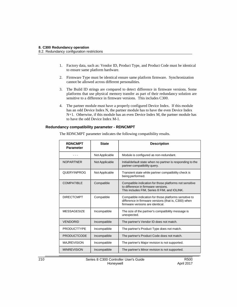
210 Series 8 C300 Controller User's Guide Honeywell
R500 April 2017
8. C300 Redundancy operation 8.2. Redundancy configuration restrictions
1. Factory data, such as: Vendor ID, Product Type, and Product Code must be identical
to ensure same platform hardware.
2. Firmware Type must be identical ensure same platform firmware. Synchronization
cannot be allowed across different personalities.
3. The Build ID strings are compared to detect difference in firmware versions. Some platforms that use physical memory transfer as part of their redundancy solution are
sensitive to a difference in firmware versions. This includes C300.
4. The partner module must have a properly configured Device Index. If this module
has an odd Device Index N, the partner module has to have the even Device Index
N+1. Otherwise, if this module has an even Device Index M, the partner module has
to have the odd Device Index M-1.
Redundancy compatibility parameter - RDNCMPT
The RDNCMPT parameter indicates the following compatibility results.
RDNCMPT Parameter
State Description
- - - Not Applicable Module is configured as non-redundant.
NOPARTNER Not Applicable Initial/default state when no partner is responding to the partner compatibility query.
QUERYINPROG Not Applicable Transient state while partner compatibility check is being performed.
COMPATIBLE Compatible Compatible indication for those platforms not sensitive to difference in firmware versions. This includes FIM, Series 8 FIM, and IOLINK.
DIRECTCMPT Compatible Compatible indication for those platforms sensitive to difference in firmware versions (that is, C300) when firmware versions are identical.
MESSAGESIZE Incompatible The size of the partner's compatibility message is unexpected.
VENDORID Incompatible The partner's Vendor ID does not match.
PRODUCTTYPE Incompatible The partner's Product Type does not match.
PRODUCTCODE Incompatible The partner's Product Code does not match.
MAJREVISION Incompatible The partner's Major revision is not supported.
MINREVISION Incompatible The partner's Minor revision is not supported.
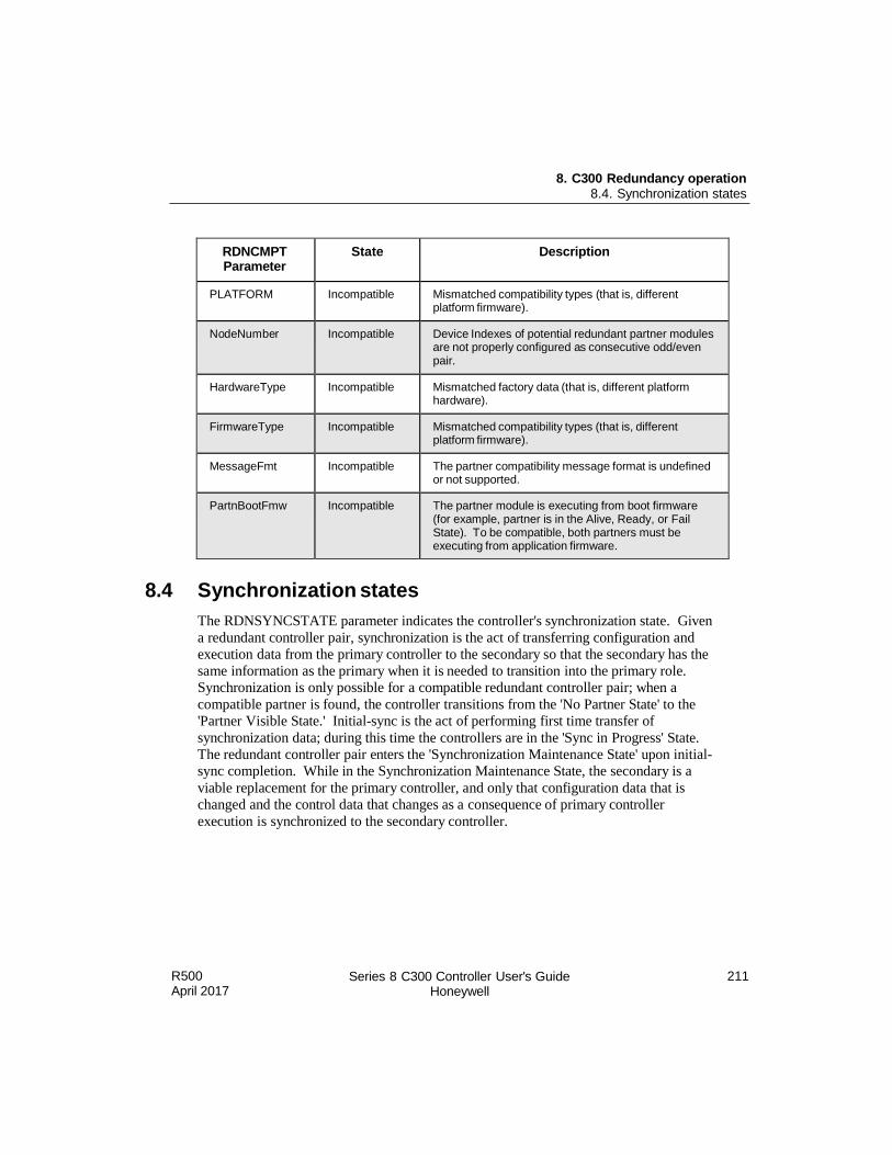
8. C300 Redundancy operation 8.4. Synchronization states
R500 April 2017
Series 8 C300 Controller User's Guide Honeywell
211
RDNCMPT Parameter
State Description
PLATFORM Incompatible Mismatched compatibility types (that is, different platform firmware).
NodeNumber Incompatible Device Indexes of potential redundant partner modules are not properly configured as consecutive odd/even pair.
HardwareType Incompatible Mismatched factory data (that is, different platform hardware).
FirmwareType Incompatible Mismatched compatibility types (that is, different platform firmware).
MessageFmt Incompatible The partner compatibility message format is undefined or not supported.
PartnBootFmw Incompatible The partner module is executing from boot firmware (for example, partner is in the Alive, Ready, or Fail State). To be compatible, both partners must be executing from application firmware.
8.4 Synchronization states
The RDNSYNCSTATE parameter indicates the controller's synchronization state. Given
a redundant controller pair, synchronization is the act of transferring configuration and
execution data from the primary controller to the secondary so that the secondary has the
same information as the primary when it is needed to transition into the primary role.
Synchronization is only possible for a compatible redundant controller pair; when a
compatible partner is found, the controller transitions from the 'No Partner State' to the
'Partner Visible State.' Initial-sync is the act of performing first time transfer of
synchronization data; during this time the controllers are in the 'Sync in Progress' State.
The redundant controller pair enters the 'Synchronization Maintenance State' upon initial-
sync completion. While in the Synchronization Maintenance State, the secondary is a
viable replacement for the primary controller, and only that configuration data that is
changed and the control data that changes as a consequence of primary controller
execution is synchronized to the secondary controller.
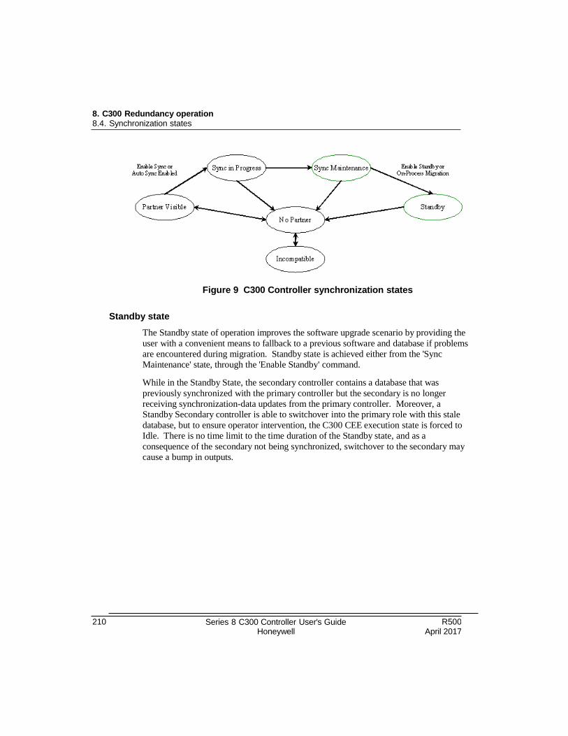
8. C300 Redundancy operation 8.4. Synchronization states
210 Series 8 C300 Controller User's Guide Honeywell
R500 April 2017
Figure 9 C300 Controller synchronization states
Standby state
The Standby state of operation improves the software upgrade scenario by providing the
user with a convenient means to fallback to a previous software and database if problems
are encountered during migration. Standby state is achieved either from the 'Sync
Maintenance' state, through the 'Enable Standby' command.
While in the Standby State, the secondary controller contains a database that was
previously synchronized with the primary controller but the secondary is no longer
receiving synchronization-data updates from the primary controller. Moreover, a
Standby Secondary controller is able to switchover into the primary role with this stale
database, but to ensure operator intervention, the C300 CEE execution state is forced to
Idle. There is no time limit to the time duration of the Standby state, and as a
consequence of the secondary not being synchronized, switchover to the secondary may
cause a bump in outputs.

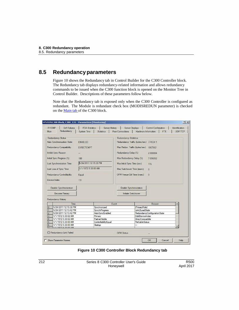
8. C300 Redundancy operation 8.5. Redundancy parameters
212 Series 8 C300 Controller User's Guide Honeywell
R500 April 2017
8.5 Redundancy parameters
Figure 10 shows the Redundancy tab in Control Builder for the C300 Controller block.
The Redundancy tab displays redundancy-related information and allows redundancy
commands to be issued when the C300 function block is opened on the Monitor Tree in
Control Builder. Descriptions of these parameters follow below.
Note that the Redundancy tab is exposed only when the C300 Controller is configured as
redundant. The Module is redundant check box (MODISREDUN parameter) is checked
on the Main tab of the C300 block.
Figure 10 C300 Controller Block Redundancy tab
8. C300 Redundancy operation 8.5. Redundancy parameters
R500 April 2017
Series 8 C300 Controller User's Guide Honeywell
213
Enable Synchronization - ENBLSYNCCMD
This command triggers an unsynchronized redundant module pair to attempt initial- synchronization. Additionally, the module's Auto-Synchronization State transitions to
ENABLED (if previously set to DISABLED).
Disable Synchronization - DSBLSYNCCMD
This command triggers a synchronizing/synchronized/standby redundant module pair to abort synchronization. Also, the module's Auto-Synchronization State to DISABLED.
Enable Standby - ENBLSTBYCMD
This command triggers a redundant controller pair in the Synchronization Maintenance
State to enter the Standby State. While in the Standby State, the secondary controller
contains a database that was previously synchronized with the primary controller but the
secondary is no longer receiving synchronization-data updates from the primary
controller. Specifically, after entering the Standby State, issue the switchover command,
and the controller with the stale database switches into the primary role with the CEE
execution state set to Idle. In the case where the Standby State was achieved through the
Enable Standby command, the Disable Synchronization command exits the Standby
State.
Auto-Synchronization State - RDNAUTOSYNC
Read-only parameter that reflects the current state of Auto-Synchronization as follows:
Enabled upon receipt of the Enable Synchronization command. When enabled, a
Primary Module automatically attempts to synchronize the Secondary, upon receipt
of any Auto-Synchronization trigger (in addition to the Enable Synchronization
command).
Disabled either upon receipt of the Disable Synchronization command or detection of
a persistent synchronization fault condition (such as, end-to-end checksum failure,
synchronization hardware failure, and so on). When disabled, user must explicitly
issue the Enable Synchronization command to reset any persistent fault condition and
(re)attempt initial-sync.
Auto synchronization triggers
When the primary controller has its Auto Synchronization State parameter set to enabled,
the redundant controller pair automatically commences initial-sync without user
intervention. More specifically, any action that results in the primary detecting a direct
compatible partner module triggers an initial sync attempt. Such as:
Reconnection of the redundancy cable.
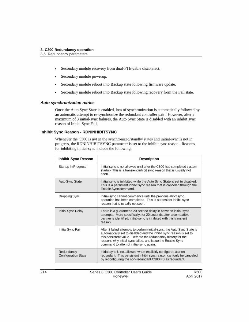
8. C300 Redundancy operation 8.5. Redundancy parameters
214 Series 8 C300 Controller User's Guide Honeywell
R500 April 2017
Secondary module recovery from dual-FTE-cable disconnect.
Secondary module powerup.
Secondary module reboot into Backup state following firmware update.
Secondary module reboot into Backup state following recovery from the Fail state.
Auto synchronization retries
Once the Auto Sync State is enabled, loss of synchronization is automatically followed by
an automatic attempt to re-synchronize the redundant controller pair. However, after a
maximum of 3 initial-sync failures, the Auto Sync State is disabled with an inhibit sync
reason of Initial Sync Fail.
Inhibit Sync Reason - RDNINHIBITSYNC
Whenever the C300 is not in the synchronized/standby states and initial-sync is not in
progress, the RDNINHIBITSYNC parameter is set to the inhibit sync reason. Reasons
for inhibiting initial-sync include the following:
Inhibit Sync Reason Description
Startup In Progress Initial sync is not allowed until after the C300 has completed system startup. This is a transient inhibit sync reason that is usually not seen.
Auto Sync State Initial sync is inhibited while the Auto Sync State is set to disabled. This is a persistent inhibit sync reason that is canceled through the Enable Sync command.
Dropping Sync Initial-sync cannot commence until the previous abort sync operation has been completed. This is a transient inhibit sync reason that is usually not seen.
Initial Sync Delay There is a guaranteed 20 second delay in between initial-sync attempts. More specifically, for 20 seconds after a compatible partner is identified, initial-sync is inhibited with this transient reason.
Initial Sync Fail After 3 failed attempts to perform initial-sync, the Auto Sync State is automatically set to disabled and the inhibit sync reason is set to this persistent value. Refer to the redundancy history for the reasons why initial-sync failed, and issue the Enable Sync command to attempt initial-sync again.
Redundancy Configuration State
Initial-sync is not allowed when explicitly configured as non- redundant. This persistent inhibit sync reason can only be canceled by reconfiguring the non-redundant C300 FB as redundant.
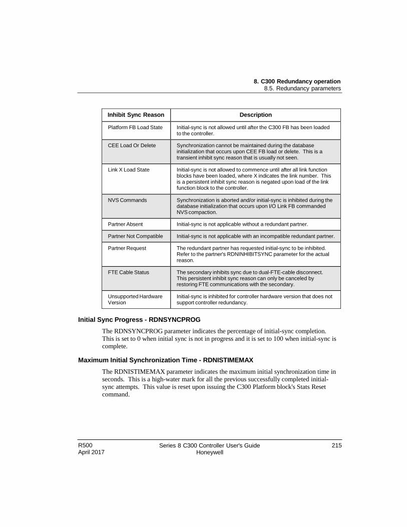
8. C300 Redundancy operation 8.5. Redundancy parameters
R500 April 2017
Series 8 C300 Controller User's Guide Honeywell
215
Inhibit Sync Reason Description
Platform FB Load State Initial-sync is not allowed until after the C300 FB has been loaded to the controller.
CEE Load Or Delete Synchronization cannot be maintained during the database initialization that occurs upon CEE FB load or delete. This is a transient inhibit sync reason that is usually not seen.
Link X Load State Initial-sync is not allowed to commence until after all link function blocks have been loaded, where X indicates the link number. This is a persistent inhibit sync reason is negated upon load of the link function block to the controller.
NVS Commands Synchronization is aborted and/or initial-sync is inhibited during the database initialization that occurs upon I/O Link FB commanded NVS compaction.
Partner Absent Initial-sync is not applicable without a redundant partner.
Partner Not Compatible Initial-sync is not applicable with an incompatible redundant partner.
Partner Request The redundant partner has requested initial-sync to be inhibited. Refer to the partner's RDNINHIBITSYNC parameter for the actual reason.
FTE Cable Status The secondary inhibits sync due to dual-FTE-cable disconnect. This persistent inhibit sync reason can only be canceled by restoring FTE communications with the secondary.
Unsupported Hardware Version
Initial-sync is inhibited for controller hardware version that does not support controller redundancy.
Initial Sync Progress - RDNSYNCPROG
The RDNSYNCPROG parameter indicates the percentage of initial-sync completion.
This is set to 0 when initial sync is not in progress and it is set to 100 when initial-sync is complete.
Maximum Initial Synchronization Time - RDNISTIMEMAX
The RDNISTIMEMAX parameter indicates the maximum initial synchronization time in
seconds. This is a high-water mark for all the previous successfully completed initial-
sync attempts. This value is reset upon issuing the C300 Platform block's Stats Reset
command.
8. C300 Redundancy operation 8.5. Redundancy parameters
216 Series 8 C300 Controller User's Guide Honeywell
R500 April 2017
Last Synchronization Time - SYNCTIMEBEG
The SYNCTIMEBEG parameter indicates the wall-clock time at which the redundant controller pair last transitioned into the Synchronization Maintenance State. This time
updates on every transition into the Synchronization Maintenance State.
Last Lost of Sync Time - SYNCTIMEEND
The SYNCTIMEEND parameter indicates the wall-clock time at which the redundant
controller pair last transitioned out of the Synchronization Maintenance State. This is
updated on every transition out of the Synchronization Maintenance State.
Redundancy Traffic
The RDNXFERAVG and RDNXFERMAX parameters indicate the average and
maximum redundancy traffic in bytes per second. These values are reset upon issuing the C300 Platform block's Stats Reset command.
Redundancy Delay
The RDNDELAYAVG and RDNDELAYMAX parameters indicate the average and
maximum redundancy delay as a percentage of control execution. This serves as a
measure of the secondary-to-primary back-pressure that varies with the secondary
controller's load of redundancy data to be processed. These are reset upon issuing the
C300 Platform block's Stats Reset command.
Conditions that result in loss of sync
Assuming a synchronized or standby redundant controller pair, the following conditions result in loss of synchronization.
Disable Sync command (from Primary or Secondary Platform FB).
Redundancy cable (private path) between Primary and Secondary controllers is lost.
Both IOL channels connected to Secondary C300 I/O Link X are lost where:
X is the I/O Link number (that is, equally applies to either I/O Link).
The IOLINK Type for this I/O Link has a value other than NONE.
Both IOL channels connected to Primary C300 I/O Link X are lost where:
X is the I/O Link number (that is, equally applies to either I/O Link).
The IOLINK Type for this I/O Link has a value other than NONE
R500 April 2017
Series 8 C300 Controller User's Guide Honeywell
217
8. C300 Redundancy operation 8.6. Switchover
There are no configured IOMs communicating on the I/O Link. In other words, it
appears to the primary controller that it has lost communication with the
Secondary I/O Link interface.
Both IOL channels connected to Primary and/or Secondary C300 I/O Link are lost
Loss of input power to Secondary controller.
Secondary controller failure.
Removing the powered Secondary controller module from its IOTA.
Conditions that do not result in loss of sync
Assuming a synchronized or standby redundant controller pair, the following conditions do not result in loss of synchronization.
Single FTE link to Primary and/or Secondary controller is lost.
Single IOL channel connected to Primary and/or Secondary C300 I/O Link is lost.
8.6 Switchover
A switchover describes the process where a Synchronized or Standby Secondary
controller assumes the role of the Primary controller. A switchover can be triggered
immediately upon the detection of a fault in the Primary or upon the receipt of an
operator command. Depending on the switchover trigger, the original Primary controller
attempts to reboot into the secondary role, but this controller is not immediately able to
participate in another switchover operation. Specifically, after the new secondary reboots
into the secondary role, it must first perform and complete initial-synchronization before
another switchover is allowed.
Initiate Switchover - SWITCHCMD
The Switchover command triggers a realistic switchover scenario. The original primary
controller reboots into the secondary role and the Synchronized or Standby Secondary controller assumes the primary role to continue control operations.
Max Switchover Time - RDNSOTIMEMAX
The RDNSOTIMEMAX parameter indicates the maximum switchover time in
milliseconds. This is a high-water mark for all the previous switchover occurrences. This value is reset upon issuing the C300 Platform block's Stats Reset command.
218 Series 8 C300 Controller User's Guide Honeywell
R500 April 2017
8. C300 Redundancy operation 8.6. Switchover
Conditions that result in switchover
The Secondary controller must be in either the Synchronized state or Standby state for a switchover to occur. The following conditions result in a switchover:
Execution of a Switchover command (from Primary or Secondary Platform FB).
Loss of both FTE links to Primary controller.
Loss of both IOL channels connected to Primary C300 I/O Link X,
where:
X is the I/O Link number (that is, equally applies to either I/O Link).
The IOLINK Type for this I/O Link has a value other than NONE.
There is at least one configured IOM communicating on the I/O Link.
ATTENTION Controller redundancy protects against all single faults and some dual faults. The Primary C300 Dual IOL Cable Disconnect switchover trigger is a dual fault that cannot be detected until after some control has been back-initialized with failsafe data. Although this dual fault affects control, switchover provides automatic recovery that does not require the operator to diagnose how to deal with a primary that has a complete loss of IOM view.
Loss of input power to Primary controller
Primary controller failure
Removal of the powered Primary controller module from its IOTA
In the case of an unsynchronized redundant controller pair with both controllers
experiencing a dual-FTE cable disconnect. The FTE reconnect to the secondary controller results in initial-sync followed by immediate switchover.
Conditions that do not result in a switchover
These conditions do not result in a switchover:
Loss of redundancy cable (private path) between Primary and Secondary controllers.
Loss of one or both FTE links to Secondary controller.
Loss of one or both IOL channels connected to Secondary C300 I/O LINK.
Loss of input power to Secondary controller.
R500 April 2017
Series 8 C300 Controller User's Guide Honeywell
219
8. C300 Redundancy operation 8.7. Redundancy history
Secondary controller failure.
Removal of the powered Secondary controller module from its IOTA.
Inserting any controller module into a powered Secondary IOTA.
Loss of a single FTE link to Primary controller.
Loss of a single IOL channel connected to Primary C300 I/O Link.
Data communication failures with Secondary controller during synchronization.
Become Primary command - BECMPRICMD
The Become Primary command is used to cause an unsynchronized secondary module to
transition into the primary role in the absence of a partner module. Specifically, this
command applies only if the unsynchronized secondary has no view to a partner module
across the redundancy cable and the primary IP address is not occupied.
8.7 Redundancy history
The C300 and Series 8 FIM support a table with 16 entries of redundancy history. There
are 3 columns representing redundancy history time, state, and reason. The controller
internally implements a circular list so that only the most recent 16 entries are retained
once the number of redundancy history exceeds 16.
RDNHISTTIME - Redundancy History Time. The system time captured at the time
the entry was added to the table.
RDNHISTSTATE - Redundancy History State. Indicates milestones with respect to
redundancy-related activities like redundancy role states, compatibility states,
synchronization states, user commands, sync abort indication, and role change
indication. Set to dashes "- - -" when entry not yet initialized.
RDNHISTREASON - Redundancy History Reason. Optionally indicates rationale
for the occurrence of the associated RDNHISTSTATE entries. Includes reason for
loss-of-sync, redundancy role change, commencing initial sync, and partner
incompatibility. Set to dashes "- - -" when entry not applicable (or entry not yet
initialized).
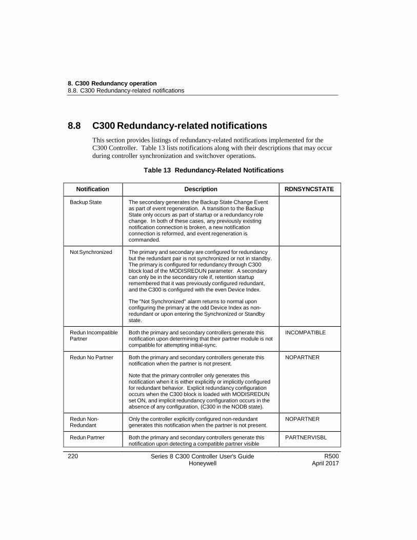
8. C300 Redundancy operation 8.8. C300 Redundancy-related notifications
220 Series 8 C300 Controller User's Guide Honeywell
R500 April 2017
8.8 C300 Redundancy-related notifications
This section provides listings of redundancy-related notifications implemented for the
C300 Controller. Table 13 lists notifications along with their descriptions that may occur
during controller synchronization and switchover operations.
Table 13 Redundancy-Related Notifications
Notification Description RDNSYNCSTATE
Backup State The secondary generates the Backup State Change Event as part of event regeneration. A transition to the Backup State only occurs as part of startup or a redundancy role change. In both of these cases, any previously existing notification connection is broken, a new notification connection is reformed, and event regeneration is commanded.
Not Synchronized The primary and secondary are configured for redundancy but the redundant pair is not synchronized or not in standby. The primary is configured for redundancy through C300 block load of the MODISREDUN parameter. A secondary can only be in the secondary role if, retention startup remembered that it was previously configured redundant, and the C300 is configured with the even Device Index.
The "Not Synchronized" alarm returns to normal upon configuring the primary at the odd Device Index as non- redundant or upon entering the Synchronized or Standby state.
Redun Incompatible Partner
Both the primary and secondary controllers generate this notification upon determining that their partner module is not compatible for attempting initial-sync.
INCOMPATIBLE
Redun No Partner Both the primary and secondary controllers generate this notification when the partner is not present.
Note that the primary controller only generates this notification when it is either explicitly or implicitly configured for redundant behavior. Explicit redundancy configuration occurs when the C300 block is loaded with MODISREDUN set ON, and implicit redundancy configuration occurs in the absence of any configuration, (C300 in the NODB state).
NOPARTNER
Redun Non- Redundant
Only the controller explicitly configured non-redundant generates this notification when the partner is not present.
NOPARTNER
Redun Partner Both the primary and secondary controllers generate this notification upon detecting a compatible partner visible
PARTNERVISBL
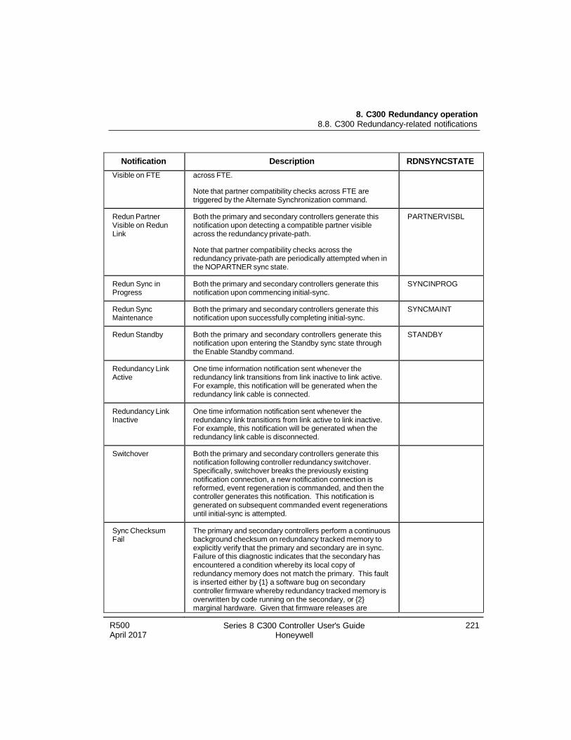
R500 April 2017
Series 8 C300 Controller User's Guide Honeywell
221
8. C300 Redundancy operation 8.8. C300 Redundancy-related notifications
Notification Description RDNSYNCSTATE
Visible on FTE across FTE.
Note that partner compatibility checks across FTE are triggered by the Alternate Synchronization command.
Redun Partner Visible on Redun Link
Both the primary and secondary controllers generate this notification upon detecting a compatible partner visible across the redundancy private-path.
Note that partner compatibility checks across the redundancy private-path are periodically attempted when in the NOPARTNER sync state.
PARTNERVISBL
Redun Sync in Progress
Both the primary and secondary controllers generate this notification upon commencing initial-sync.
SYNCINPROG
Redun Sync Maintenance
Both the primary and secondary controllers generate this notification upon successfully completing initial-sync.
SYNCMAINT
Redun Standby Both the primary and secondary controllers generate this notification upon entering the Standby sync state through the Enable Standby command.
STANDBY
Redundancy Link Active
One time information notification sent whenever the redundancy link transitions from link inactive to link active. For example, this notification will be generated when the redundancy link cable is connected.
Redundancy Link Inactive
One time information notification sent whenever the redundancy link transitions from link active to link inactive. For example, this notification will be generated when the redundancy link cable is disconnected.
Switchover Both the primary and secondary controllers generate this notification following controller redundancy switchover. Specifically, switchover breaks the previously existing notification connection, a new notification connection is reformed, event regeneration is commanded, and then the controller generates this notification. This notification is generated on subsequent commanded event regenerations until initial-sync is attempted.
Sync Checksum Fail
The primary and secondary controllers perform a continuous background checksum on redundancy tracked memory to explicitly verify that the primary and secondary are in sync. Failure of this diagnostic indicates that the secondary has encountered a condition whereby its local copy of redundancy memory does not match the primary. This fault is inserted either by {1} a software bug on secondary controller firmware whereby redundancy tracked memory is overwritten by code running on the secondary, or {2} marginal hardware. Given that firmware releases are
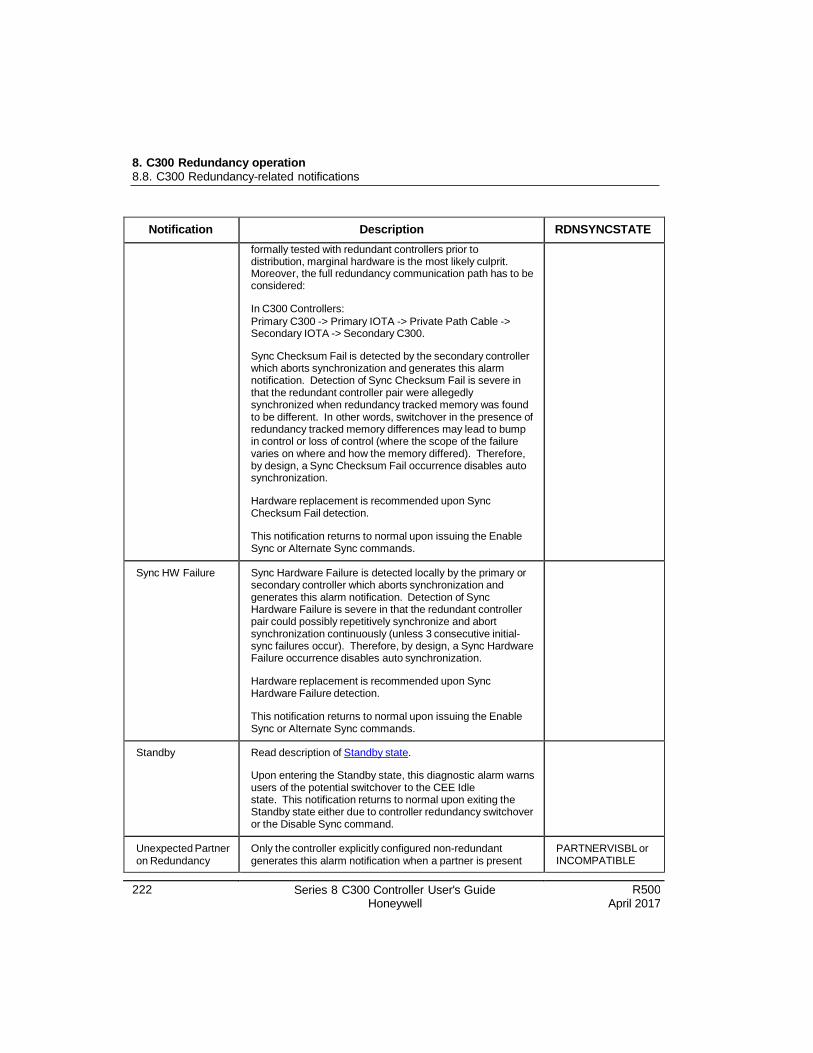
8. C300 Redundancy operation 8.8. C300 Redundancy-related notifications
222 Series 8 C300 Controller User's Guide Honeywell
R500 April 2017
Notification Description RDNSYNCSTATE
formally tested with redundant controllers prior to distribution, marginal hardware is the most likely culprit. Moreover, the full redundancy communication path has to be considered:
In C300 Controllers:
Primary C300 -> Primary IOTA -> Private Path Cable -> Secondary IOTA -> Secondary C300.
Sync Checksum Fail is detected by the secondary controller which aborts synchronization and generates this alarm notification. Detection of Sync Checksum Fail is severe in that the redundant controller pair were allegedly synchronized when redundancy tracked memory was found to be different. In other words, switchover in the presence of redundancy tracked memory differences may lead to bump in control or loss of control (where the scope of the failure varies on where and how the memory differed). Therefore, by design, a Sync Checksum Fail occurrence disables auto synchronization.
Hardware replacement is recommended upon Sync Checksum Fail detection.
This notification returns to normal upon issuing the Enable Sync or Alternate Sync commands.
Sync HW Failure Sync Hardware Failure is detected locally by the primary or secondary controller which aborts synchronization and generates this alarm notification. Detection of Sync Hardware Failure is severe in that the redundant controller pair could possibly repetitively synchronize and abort synchronization continuously (unless 3 consecutive initial- sync failures occur). Therefore, by design, a Sync Hardware Failure occurrence disables auto synchronization.
Hardware replacement is recommended upon Sync Hardware Failure detection.
This notification returns to normal upon issuing the Enable Sync or Alternate Sync commands.
Standby Read description of Standby state.
Upon entering the Standby state, this diagnostic alarm warns users of the potential switchover to the CEE Idle state. This notification returns to normal upon exiting the Standby state either due to controller redundancy switchover or the Disable Sync command.
Unexpected Partner on Redundancy
Only the controller explicitly configured non-redundant generates this alarm notification when a partner is present
PARTNERVISBL or INCOMPATIBLE
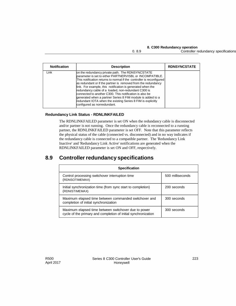
R500 April 2017
Series 8 C300 Controller User's Guide Honeywell
223
8. C300 Redundancy operation 0. 8.9 Controller redundancy specifications
Notification Description RDNSYNCSTATE
Link on the redundancy private path. The RDNSYNCSTATE parameter is set to either PARTNERVISBL or INCOMPATIBLE. This notification returns to normal if the controller is reconfigured as redundant or if the partner is removed from the redundancy link. For example, this notification is generated when the redundancy cable of a loaded, non-redundant C300 is connected to another C300. This notification is also be generated when a partner Series 8 FIM module is added to a redundant IOTA when the existing Series 8 FIM is explicitly configured as nonredundant.
Redundancy Link Status - RDNLINKFAILED
The RDNLINKFAILED parameter is set ON when the redundancy cable is disconnected
and/or partner is not running. Once the redundancy cable is reconnected to a running
partner, the RDNLINKFAILED parameter is set OFF. Note that this parameter reflects
the physical status of the cable (connected vs. disconnected) and in no way indicates if
the redundancy cable is connected to a compatible partner. The 'Redundancy Link
Inactive' and 'Redundancy Link Active' notifications are generated when the
RDNLINKFAILED parameter is set ON and OFF, respectively.
8.9 Controller redundancy specifications
Specification
Control processing switchover interruption time (RDNSOTIMEMAX)
500 milliseconds
Initial synchronization time (from sync start to completion) (RDNISTIMEMAX)
200 seconds
Maximum elapsed time between commanded switchover and completion of initial synchronization
300 seconds
Maximum elapsed time between switchover due to power cycle of the primary and completion of initial synchronization
300 seconds

8. C300 Redundancy operation 8.8. C300 Redundancy-related notifications
222 Series 8 C300 Controller User's Guide Honeywell
R500 April 2017

R500 April 2017
Series 8 C300 Controller User's Guide Honeywell
225
8. C300 Redundancy operation 0. 8.9 Controller redundancy specifications

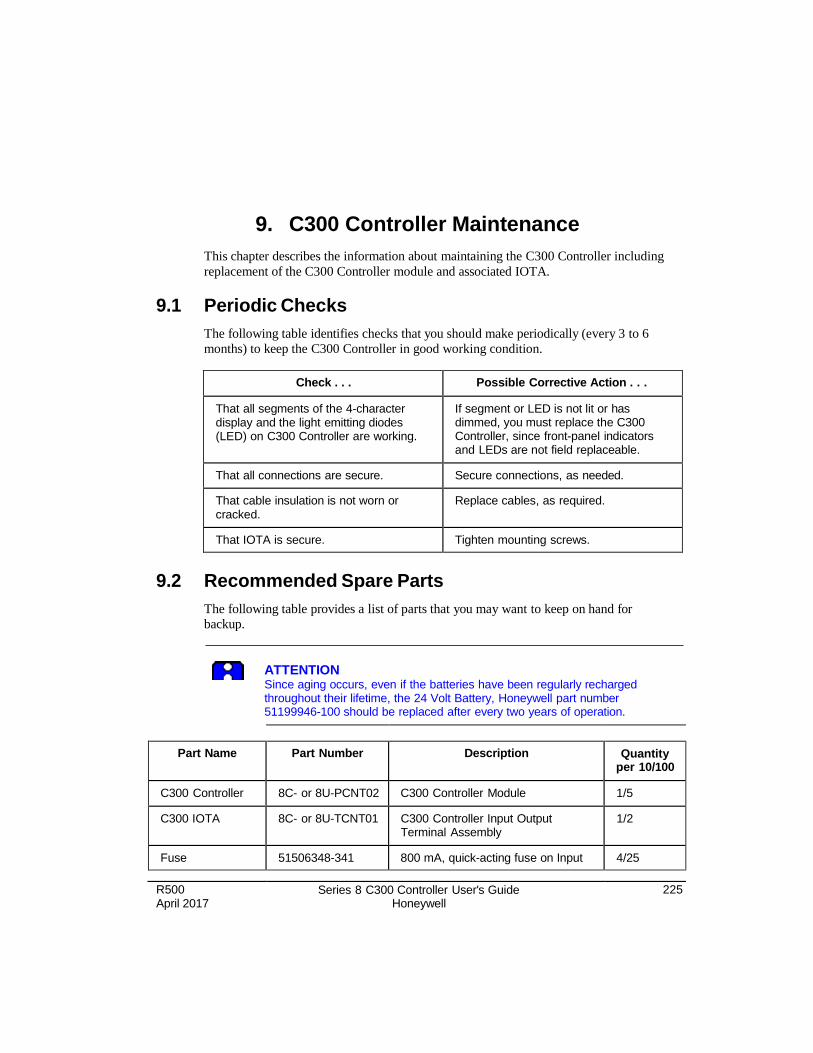
R500 April 2017
Series 8 C300 Controller User's Guide Honeywell
225
9. C300 Controller Maintenance
This chapter describes the information about maintaining the C300 Controller including
replacement of the C300 Controller module and associated IOTA.
9.1 Periodic Checks
The following table identifies checks that you should make periodically (every 3 to 6
months) to keep the C300 Controller in good working condition.
Check . . . Possible Corrective Action . . .
That all segments of the 4-character display and the light emitting diodes (LED) on C300 Controller are working.
If segment or LED is not lit or has dimmed, you must replace the C300 Controller, since front-panel indicators and LEDs are not field replaceable.
That all connections are secure. Secure connections, as needed.
That cable insulation is not worn or cracked.
Replace cables, as required.
That IOTA is secure. Tighten mounting screws.
9.2 Recommended Spare Parts
The following table provides a list of parts that you may want to keep on hand for
backup.
ATTENTION Since aging occurs, even if the batteries have been regularly recharged throughout their lifetime, the 24 Volt Battery, Honeywell part number 51199946-100 should be replaced after every two years of operation.
Part Name Part Number Description Quantity
per 10/100
C300 Controller 8C- or 8U-PCNT02 C300 Controller Module 1/5
C300 IOTA 8C- or 8U-TCNT01 C300 Controller Input Output Terminal Assembly
1/2
Fuse 51506348-341 800 mA, quick-acting fuse on Input 4/25
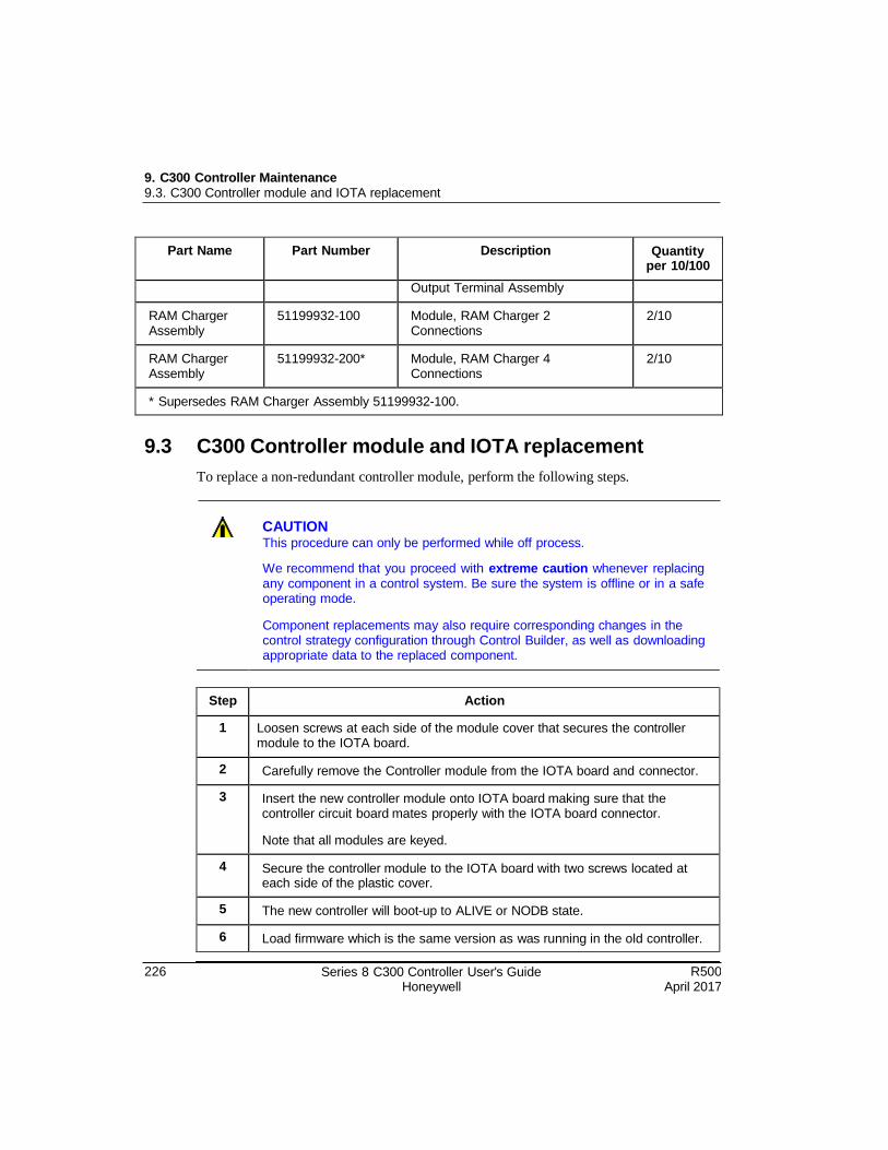
226 Series 8 C300 Controller User's Guide Honeywell
R500 April 2017
9. C300 Controller Maintenance 9.3. C300 Controller module and IOTA replacement
Part Name Part Number Description Quantity per 10/100
Output Terminal Assembly
RAM Charger Assembly
51199932-100 Module, RAM Charger 2 Connections
2/10
RAM Charger Assembly
51199932-200* Module, RAM Charger 4 Connections
2/10
* Supersedes RAM Charger Assembly 51199932-100.
9.3 C300 Controller module and IOTA replacement
To replace a non-redundant controller module, perform the following steps.
CAUTION This procedure can only be performed while off process.
We recommend that you proceed with extreme caution whenever replacing any component in a control system. Be sure the system is offline or in a safe operating mode.
Component replacements may also require corresponding changes in the control strategy configuration through Control Builder, as well as downloading appropriate data to the replaced component.
Step Action
1 Loosen screws at each side of the module cover that secures the controller module to the IOTA board.
2 Carefully remove the Controller module from the IOTA board and connector.
3 Insert the new controller module onto IOTA board making sure that the controller circuit board mates properly with the IOTA board connector.
Note that all modules are keyed.
4 Secure the controller module to the IOTA board with two screws located at each side of the plastic cover.
5 The new controller will boot-up to ALIVE or NODB state.
6 Load firmware which is the same version as was running in the old controller.
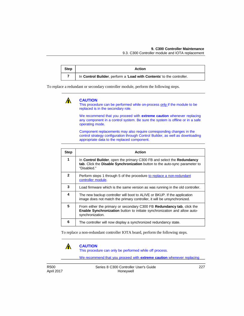
R500 April 2017
Series 8 C300 Controller User's Guide Honeywell
227
9. C300 Controller Maintenance 9.3. C300 Controller module and IOTA replacement
Step Action
7 In Control Builder, perform a 'Load with Contents' to the controller.
To replace a redundant or secondary controller module, perform the following steps.
CAUTION This procedure can be performed while on-process only if the module to be replaced is in the secondary role.
We recommend that you proceed with extreme caution whenever replacing
any component in a control system. Be sure the system is offline or in a safe operating mode.
Component replacements may also require corresponding changes in the control strategy configuration through Control Builder, as well as downloading appropriate data to the replaced component.
Step Action
1 In Control Builder, open the primary C300 FB and select the Redundancy tab. Click the Disable Synchronization button to the auto-sync parameter to
"Disabled."
2 Perform steps 1 through 5 of the procedure to replace a non-redundant controller module.
3 Load firmware which is the same version as was running in the old controller.
4 The new backup controller will boot to ALIVE or BKUP. If the application image does not match the primary controller, it will be unsynchronized.
5 From either the primary or secondary C300 FB Redundancy tab, click the Enable Synchronization button to initiate synchronization and allow auto-
synchronization.
6 The controller will now display a synchronized redundancy state.
To replace a non-redundant controller IOTA board, perform the following steps.
CAUTION This procedure can only be performed while off process.
We recommend that you proceed with extrem e caution whenever replacing
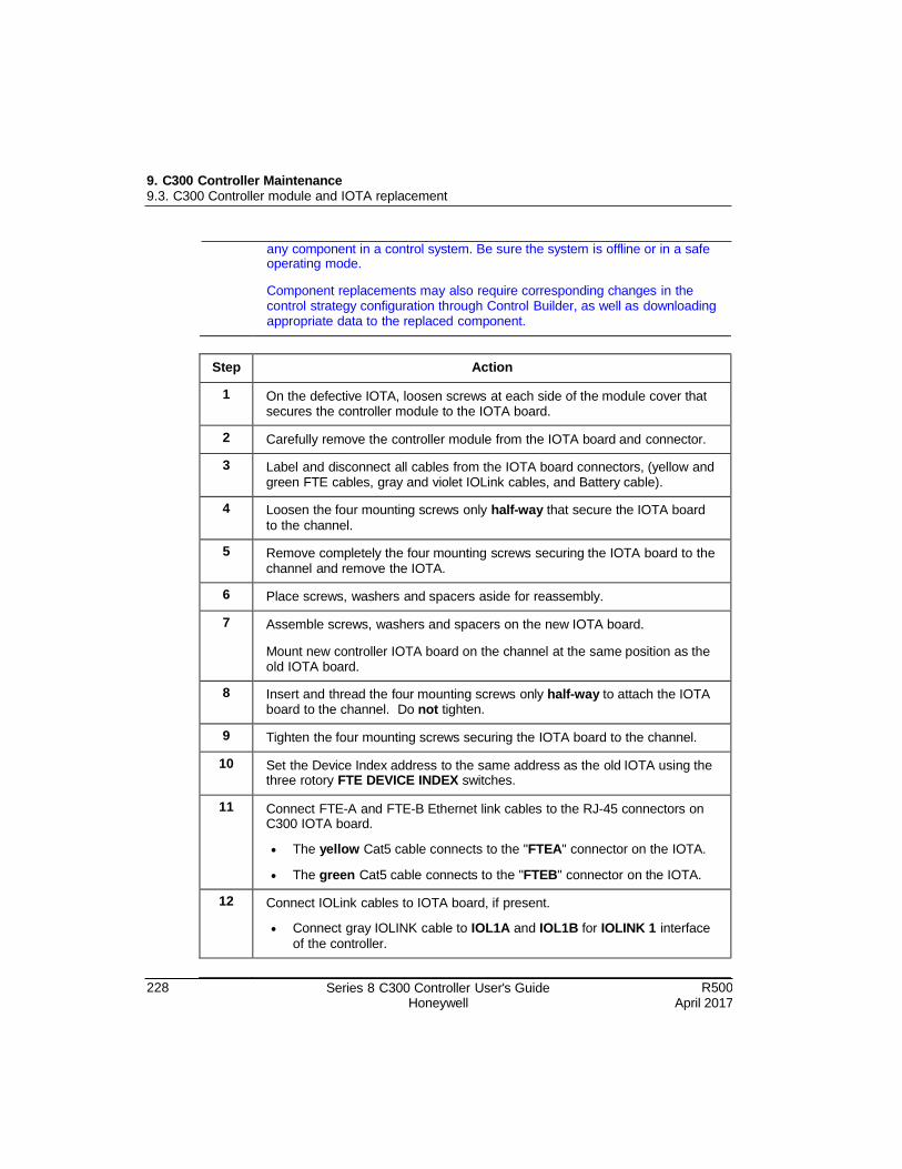
228 Series 8 C300 Controller User's Guide Honeywell
R500 April 2017
9. C300 Controller Maintenance 9.3. C300 Controller module and IOTA replacement
any component in a control system. Be sure the system is offline or in a safe operating mode.
Component replacements may also require corresponding changes in the control strategy configuration through Control Builder, as well as downloading appropriate data to the replaced component.
Step Action
1 On the defective IOTA, loosen screws at each side of the module cover that secures the controller module to the IOTA board.
2 Carefully remove the controller module from the IOTA board and connector.
3 Label and disconnect all cables from the IOTA board connectors, (yellow and green FTE cables, gray and violet IOLink cables, and Battery cable).
4 Loosen the four mounting screws only half-way that secure the IOTA board
to the channel.
5 Remove completely the four mounting screws securing the IOTA board to the channel and remove the IOTA.
6 Place screws, washers and spacers aside for reassembly.
7 Assemble screws, washers and spacers on the new IOTA board.
Mount new controller IOTA board on the channel at the same position as the old IOTA board.
8 Insert and thread the four mounting screws only half-way to attach the IOTA board to the channel. Do not tighten.
9 Tighten the four mounting screws securing the IOTA board to the channel.
10 Set the Device Index address to the same address as the old IOTA using the three rotory FTE DEVICE INDEX switches.
11 Connect FTE-A and FTE-B Ethernet link cables to the RJ-45 connectors on C300 IOTA board.
The yellow Cat5 cable connects to the "FTEA" connector on the IOTA.
The green Cat5 cable connects to the "FTEB" connector on the IOTA.
12 Connect IOLink cables to IOTA board, if present.
Connect gray IOLINK cable to IOL1A and IOL1B for IOLINK 1 interface
of the controller.
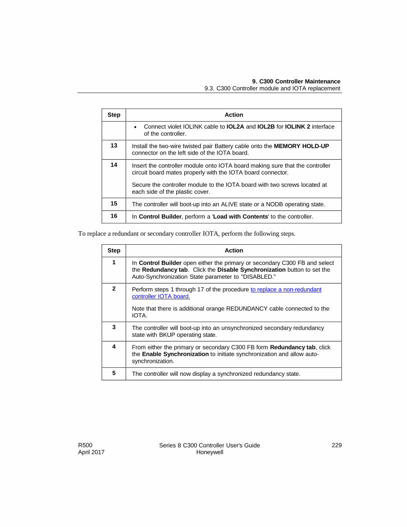
R500 April 2017
Series 8 C300 Controller User's Guide Honeywell
229
9. C300 Controller Maintenance 9.3. C300 Controller module and IOTA replacement
Step Action
Connect violet IOLINK cable to IOL2A and IOL2B for IOLINK 2 interface
of the controller.
13 Install the two-wire twisted pair Battery cable onto the MEMORY HOLD-UP connector on the left side of the IOTA board.
14 Insert the controller module onto IOTA board making sure that the controller circuit board mates properly with the IOTA board connector.
Secure the controller module to the IOTA board with two screws located at each side of the plastic cover.
15 The controller will boot-up into an ALIVE state or a NODB operating state.
16 In Control Builder, perform a 'Load with Contents' to the controller.
To replace a redundant or secondary controller IOTA, perform the following steps.
Step Action
1 In Control Builder open either the primary or secondary C300 FB and select the Redundancy tab. Click the Disable Synchronization button to set the
Auto-Synchronization State parameter to "DISABLED."
2 Perform steps 1 through 17 of the procedure to replace a non-redundant controller IOTA board.
Note that there is additional orange REDUNDANCY cable connected to the IOTA.
3 The controller will boot-up into an unsynchronized secondary redundancy state with BKUP operating state.
4 From either the primary or secondary C300 FB form Redundancy tab, click the Enable Synchronization to initiate synchronization and allow auto-
synchronization.
5 The controller will now display a synchronized redundancy state.

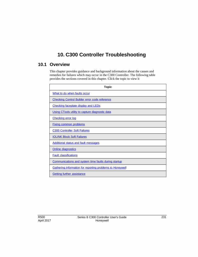
R500 April 2017
Series 8 C300 Controller User's Guide Honeywell
231
10. C300 Controller Troubleshooting
10.1 Overview
This chapter provides guidance and background information about the causes and remedies for failures which may occur in the C300 Controller. The following table
provides the sections covered in this chapter. Click the topic to view it
Topic
What to do when faults occur
Checking Control Builder error code reference
Checking faceplate display and LEDs
Using CTools utility to capture diagnostic data
Checking error log
Fixing common problems
C300 Controller Soft Failures
IOLINK Block Soft Failures
Additional status and fault messages
Online diagnostics
Fault classifications
Communications and system time faults during startup
Gathering information for reporting problems to Honeywell
Getting further assistance
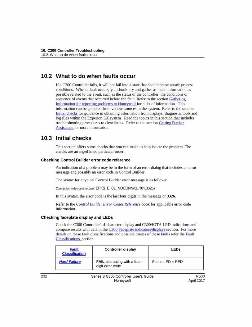
232 Series 8 C300 Controller User's Guide Honeywell
R500 April 2017
10. C300 Controller Troubleshooting 10.2. What to do when faults occur
10.2 What to do when faults occur
If a C300 Controller fails, it will not fail into a state that should cause unsafe process
conditions. When a fault occurs, you should try and gather as much information as
possible related to the event, such as the status of the controller, the conditions or
sequence of events that occurred before the fault. Refer to the section Gathering
Information for reporting problems to Honeywell for a list of information. This
information can be gathered from various sources in the system. Refer to the section
Initial checks for guidance in obtaining information from displays, diagnostic tools and
log files within the Experion LX system. Read the topics in this section that includes
troubleshooting procedures to clear faults. Refer to the section Getting Further
Assistance for more information.
10.3 Initial checks
This section offers some checks that you can make to help isolate the problem. The
checks are arranged in no particular order.
Checking Control Builder error code reference
An indication of a problem may be in the form of an error dialog that includes an error message and possibly an error code in Control Builder.
The syntax for a typical Control Builder error message is as follows:
Connection to device is not open EPKS_E_CL_NOCONN(6L.101.3326)
In this syntax, the error code is the last four digits in the message or 3326.
Refer to the Control Builder Error Codes Reference book for applicable error code
information.
Checking faceplate display and LEDs
Check the C300 Controller's 4-character display and C300/IOTA LED indications and
compare results with data in the C300 Faceplate indicators/displays section. For more
details on these fault classifications and possible causes of these faults refer the Fault
Classifications section.
Fault Classification
Controller display LEDs
Hard Failure FAIL alternating with a four-
digit error code Status LED = RED
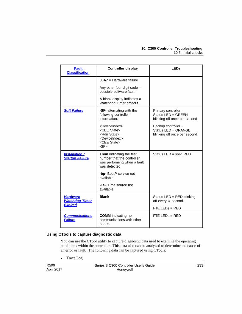
10. C300 Controller Troubleshooting 10.3. Initial checks
R500 April 2017
Series 8 C300 Controller User's Guide Honeywell
233
Fault Classification
Controller display LEDs
03A7 = Hardware failure
Any other four digit code = possible software fault
A blank display indicates a Watchdog Timer timeout.
Soft Failure -SF- alternating with the following controller information:
<DeviceIndex> <CEE State> <Rdn State> <DeviceIndex> <CEE State> -SF -
Primary controller -
Status LED = GREEN blinking off once per second
Backup controller -
Status LED = ORANGE blinking off once per second
Installation / Startup Failure
Tnnn indicating the test number that the controller was performing when a fault was detected.
-bp- BootP service not
available
-TS- Time source not
available.
Status LED = solid RED
Hardware Watchdog Timer Expired
Blank Status LED = RED blinking off every ¼ second.
FTE LEDs = RED
Communications Failure
COMM indicating no communications with other nodes.
FTE LEDs = RED
Using CTools to capture diagnostic data
You can use the CTool utility to capture diagnostic data used to examine the operating
conditions within the controller. This data also can be analyzed to determine the cause of
an error or fault. The following data can be captured using CTools:
Trace Log
234 Series 8 C300 Controller User's Guide Honeywell
R500 April 2017
10. C300 Controller Troubleshooting 10.4. Fixing common problems
Registers
SSP
Call Stack
Instructions
Viewing flash log
The Flash.txt log provides a list of firmware updates that have been initiated.
To view the log, navigate to this file location on the server:
C:\Program Files\Honeywell\Experion\Engineering Tools\system\bin\Flash.txt.
Viewing release information log
The ReleaseInfo.txt log provides a list of Experion LX software releases that have been
installed on the computer.
To view the log, navigate to this file location on the server:
C:\Program Files\Honeywell\Experion\Engineering Tools\system\bin\ReleaseInfo.txt.
Checking server point build log
The SvrPtBld_servername.txt log provides list of process (CB) points built in the server
database.
To check the log, navigate to this file location on the server: C:\Program
Files\Honeywell\Experion PKS\Engineering Tools\temp\SvrPtBld_servername.txt.
Checking server point build error log
The svrptblderr_servername.txt log provides list of any errors associated with process (CB) points built in the server database
To check the log, navigate to this file location on the server: C:\Program Files\Honeywell\Experion PKS\Engineering Tools\temp\svrptblderr_servername.txt.
Checking error log
The Errlog_n.txt log provides a running list of Control Builder detected errors in chronological order. The n represents any number that is assigned to the most recent log.
To check the log, navigate to this file location on the server:
C:\ProgramData\Honeywell\Experion PKS\ErrLog_n.txt.
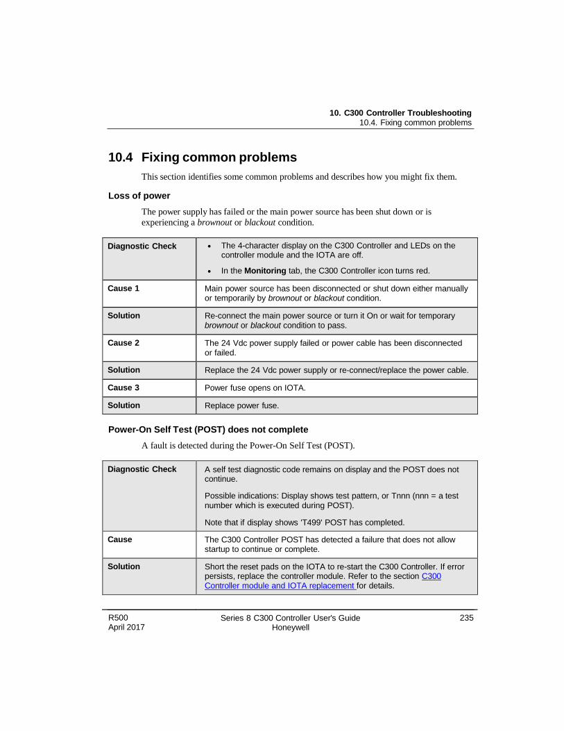
R500 April 2017
Series 8 C300 Controller User's Guide Honeywell
235
10. C300 Controller Troubleshooting 10.4. Fixing common problems
10.4 Fixing common problems
This section identifies some common problems and describes how you might fix them.
Loss of power
The power supply has failed or the main power source has been shut down or is
experiencing a brownout or blackout condition.
Diagnostic Check The 4-character display on the C300 Controller and LEDs on the controller module and the IOTA are off.
In the Monitoring tab, the C300 Controller icon turns red.
Cause 1 Main power source has been disconnected or shut down either manually or temporarily by brownout or blackout condition.
Solution Re-connect the main power source or turn it On or wait for temporary brownout or blackout condition to pass.
Cause 2 The 24 Vdc power supply failed or power cable has been disconnected or failed.
Solution Replace the 24 Vdc power supply or re-connect/replace the power cable.
Cause 3 Power fuse opens on IOTA.
Solution Replace power fuse.
Power-On Self Test (POST) does not complete
A fault is detected during the Power-On Self Test (POST).
Diagnostic Check A self test diagnostic code remains on display and the POST does not continue.
Possible indications: Display shows test pattern, or Tnnn (nnn = a test number which is executed during POST).
Note that if display shows 'T499' POST has completed.
Cause The C300 Controller POST has detected a failure that does not allow startup to continue or complete.
Solution Short the reset pads on the IOTA to re-start the C300 Controller. If error persists, replace the controller module. Refer to the section C300 Controller module and IOTA replacement for details.
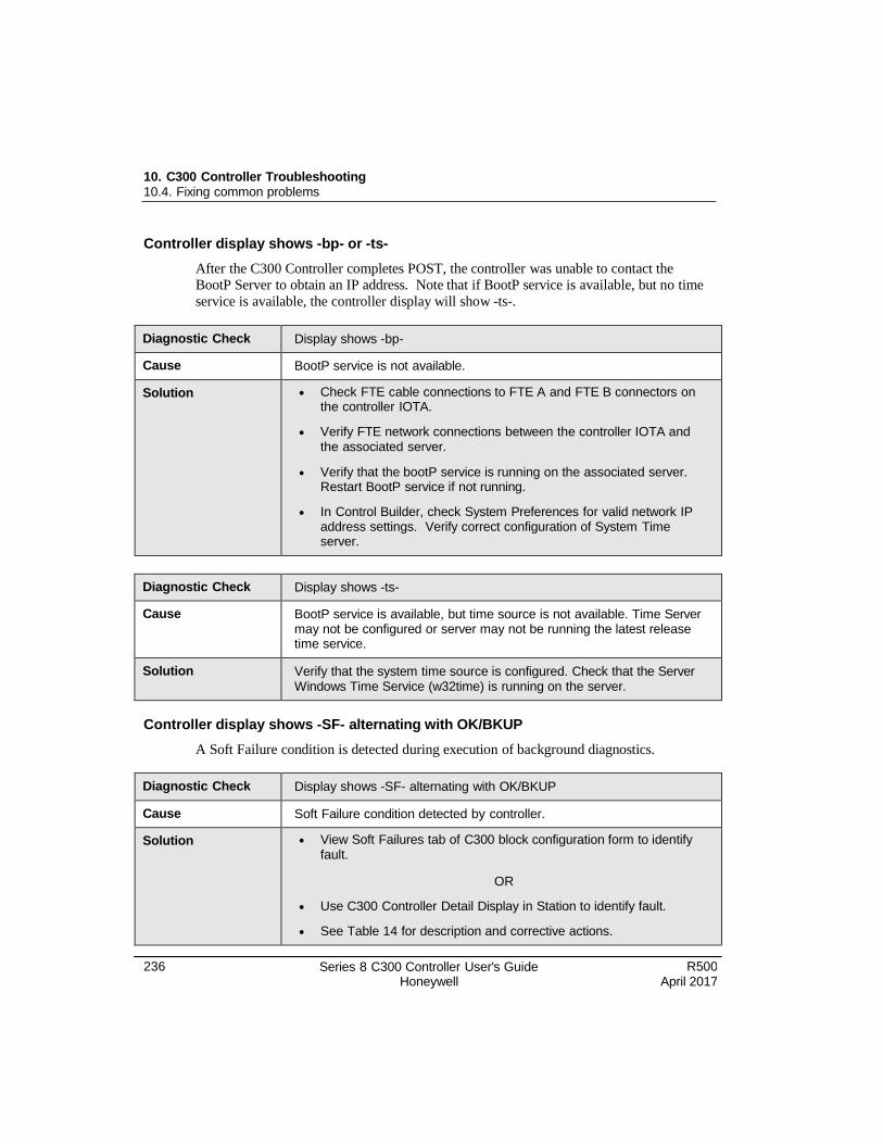
236 Series 8 C300 Controller User's Guide Honeywell
R500 April 2017
10. C300 Controller Troubleshooting 10.4. Fixing common problems
Controller display shows -bp- or -ts-
After the C300 Controller completes POST, the controller was unable to contact the BootP Server to obtain an IP address. Note that if BootP service is available, but no time
service is available, the controller display will show -ts-.
Diagnostic Check Display shows -bp-
Cause BootP service is not available.
Solution Check FTE cable connections to FTE A and FTE B connectors on the controller IOTA.
Verify FTE network connections between the controller IOTA and the associated server.
Verify that the bootP service is running on the associated server. Restart BootP service if not running.
In Control Builder, check System Preferences for valid network IP address settings. Verify correct configuration of System Time server.
Diagnostic Check Display shows -ts-
Cause BootP service is available, but time source is not available. Time Server may not be configured or server may not be running the latest release time service.
Solution Verify that the system time source is configured. Check that the Server Windows Time Service (w32time) is running on the server.
Controller display shows -SF- alternating with OK/BKUP
A Soft Failure condition is detected during execution of background diagnostics.
Diagnostic Check Display shows -SF- alternating with OK/BKUP
Cause Soft Failure condition detected by controller.
Solution View Soft Failures tab of C300 block configuration form to identify fault.
OR
Use C300 Controller Detail Display in Station to identify fault.
See Table 14 for description and corrective actions.
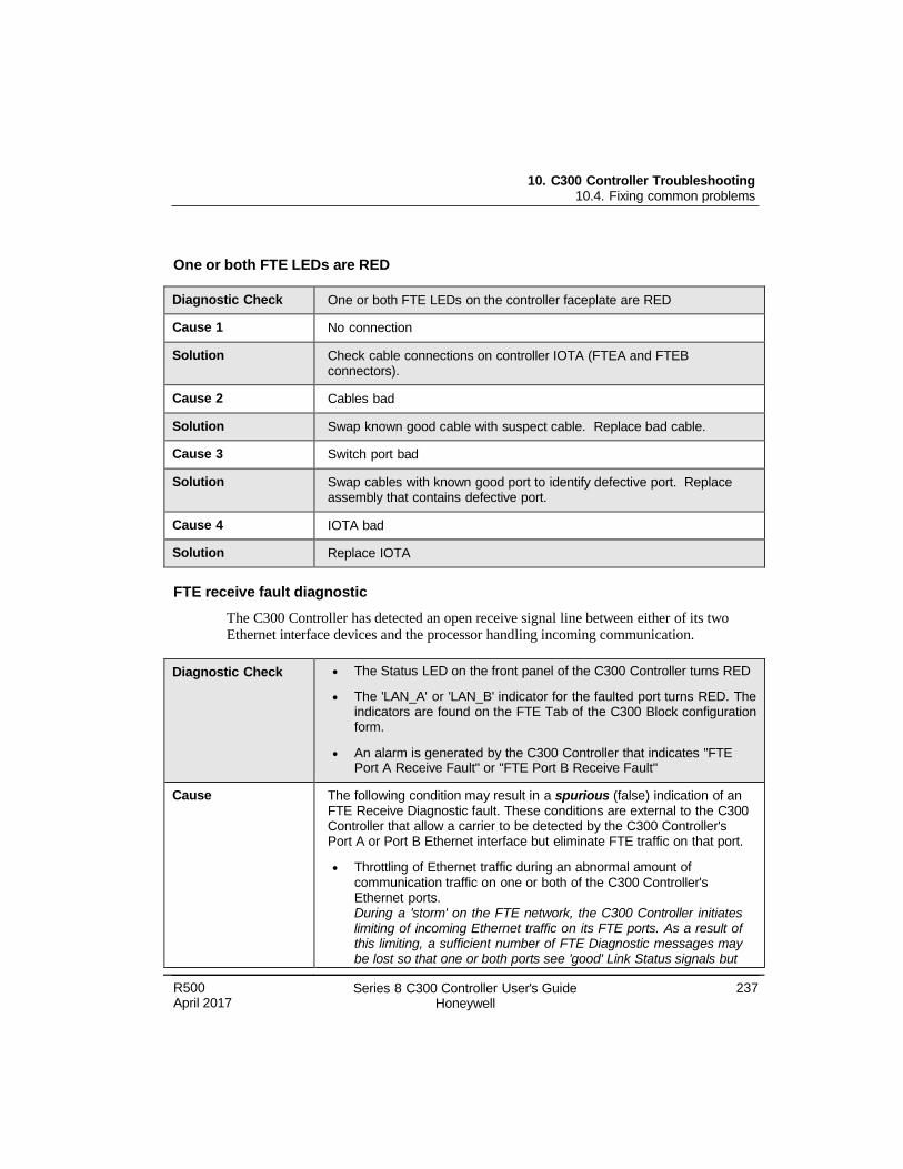
R500 April 2017
Series 8 C300 Controller User's Guide Honeywell
237
10. C300 Controller Troubleshooting 10.4. Fixing common problems
One or both FTE LEDs are RED
Diagnostic Check One or both FTE LEDs on the controller faceplate are RED
Cause 1 No connection
Solution Check cable connections on controller IOTA (FTEA and FTEB connectors).
Cause 2 Cables bad
Solution Swap known good cable with suspect cable. Replace bad cable.
Cause 3 Switch port bad
Solution Swap cables with known good port to identify defective port. Replace assembly that contains defective port.
Cause 4 IOTA bad
Solution Replace IOTA
FTE receive fault diagnostic
The C300 Controller has detected an open receive signal line between either of its two Ethernet interface devices and the processor handling incoming communication.
Diagnostic Check The Status LED on the front panel of the C300 Controller turns RED
The 'LAN_A' or 'LAN_B' indicator for the faulted port turns RED. The indicators are found on the FTE Tab of the C300 Block configuration form.
An alarm is generated by the C300 Controller that indicates "FTE Port A Receive Fault" or "FTE Port B Receive Fault"
Cause The following condition may result in a spurious (false) indication of an FTE Receive Diagnostic fault. These conditions are external to the C300 Controller that allow a carrier to be detected by the C300 Controller's Port A or Port B Ethernet interface but eliminate FTE traffic on that port.
Throttling of Ethernet traffic during an abnormal amount of communication traffic on one or both of the C300 Controller's Ethernet ports. During a 'storm' on the FTE network, the C300 Controller initiates limiting of incoming Ethernet traffic on its FTE ports. As a result of this limiting, a sufficient number of FTE Diagnostic messages may be lost so that one or both ports see 'good' Link Status signals but
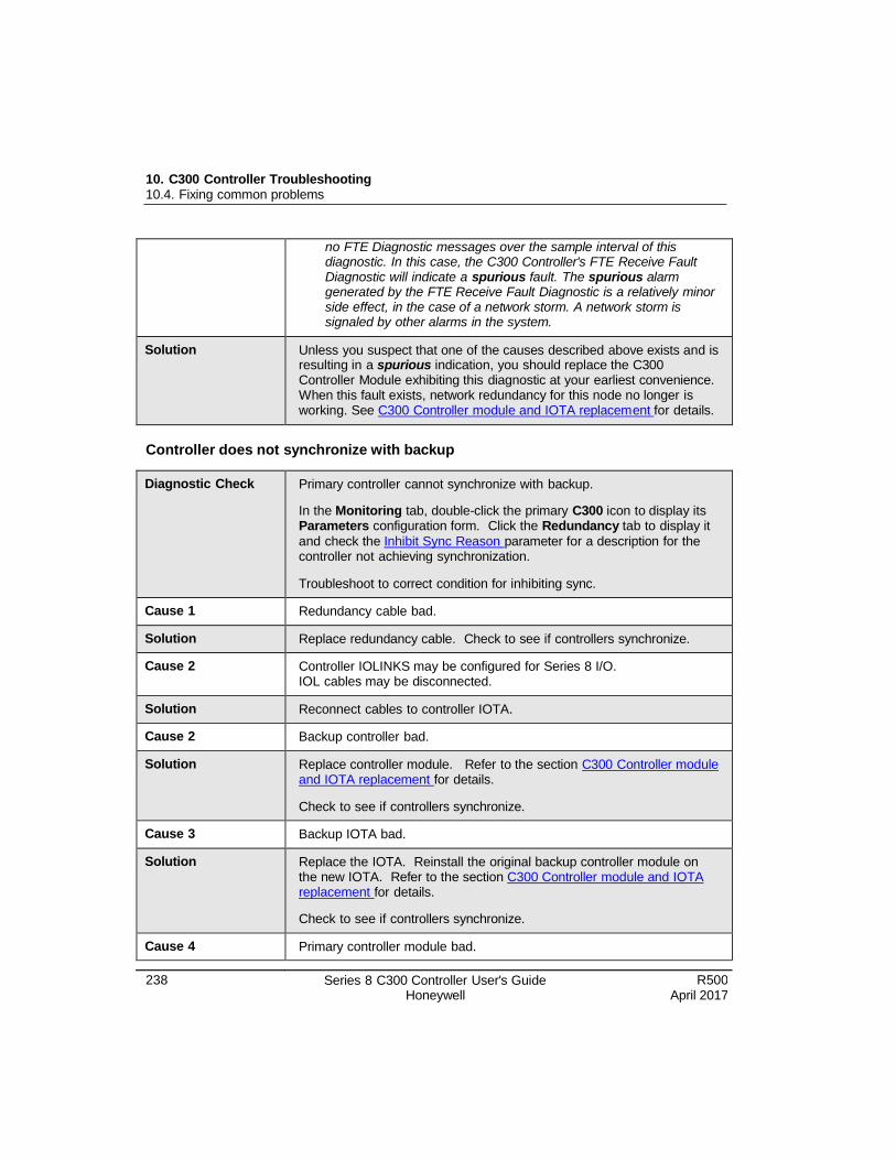
238 Series 8 C300 Controller User's Guide Honeywell
R500 April 2017
10. C300 Controller Troubleshooting 10.4. Fixing common problems
no FTE Diagnostic messages over the sample interval of this diagnostic. In this case, the C300 Controller's FTE Receive Fault Diagnostic will indicate a spurious fault. The spurious alarm generated by the FTE Receive Fault Diagnostic is a relatively minor side effect, in the case of a network storm. A network storm is signaled by other alarms in the system.
Solution Unless you suspect that one of the causes described above exists and is resulting in a spurious indication, you should replace the C300 Controller Module exhibiting this diagnostic at your earliest convenience. When this fault exists, network redundancy for this node no longer is working. See C300 Controller module and IOTA replacem ent for details.
Controller does not synchronize with backup
Diagnostic Check Primary controller cannot synchronize with backup.
In the Monitoring tab, double-click the primary C300 icon to display its Parameters configuration form. Click the Redundancy tab to display it
and check the Inhibit Sync Reason parameter for a description for the controller not achieving synchronization.
Troubleshoot to correct condition for inhibiting sync.
Cause 1 Redundancy cable bad.
Solution Replace redundancy cable. Check to see if controllers synchronize.
Cause 2 Controller IOLINKS may be configured for Series 8 I/O. IOL cables may be disconnected.
Solution Reconnect cables to controller IOTA.
Cause 2 Backup controller bad.
Solution Replace controller module. Refer to the section C300 Controller module and IOTA replacement for details.
Check to see if controllers synchronize.
Cause 3 Backup IOTA bad.
Solution Replace the IOTA. Reinstall the original backup controller module on the new IOTA. Refer to the section C300 Controller module and IOTA replacement for details.
Check to see if controllers synchronize.
Cause 4 Primary controller module bad.
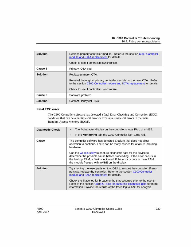
R500 April 2017
Series 8 C300 Controller User's Guide Honeywell
239
10. C300 Controller Troubleshooting 10.4. Fixing common problems
Solution Replace primary controller module. Refer to the section C300 Controller module and IOTA replacement for details.
Check to see if controllers synchronize.
Cause 5 Primary IOTA bad.
Solution Replace primary IOTA.
Reinstall the original primary controller module on the new IOTA. Refer to the section C300 Controller module and IOTA replacement for details.
Check to see if controllers synchronize.
Cause 6 Software problem.
Solution Contact Honeywell TAC.
Fatal ECC error
The C300 Controller software has detected a fatal Error Checking and Correction (ECC)
condition that can be a multiple-bit error or excessive single-bit errors in the main
Random Access Memory (RAM).
Diagnostic Check The 4-character display on the controller shows FAIL or mMBE.
In the Monitoring tab, the C300 Controller icon turns red.
Cause The controller software has detected a failure that does not allow operation to continue. There can be many causes for a failure including hardware.
Use the CTools utility to capture diagnostic data for the device to determine the possible cause before proceeding. If the error occurs in the backup RAM, a fault is indicated. If the error occurs in main RAM, the module freezes with mMBE on the display.
Solution Try shorting the reset pads on the IOTA to re-start the controller. If error persists, replace the controller. Refer to the section C300 Controller module and IOTA replacement for details.
Check the Trace log for breadcrumbs that occurred prior to the event. Refer to the section Using CTools for capturing diagnostic data for more information. Provide the results of the trace log to TAC for analysis.
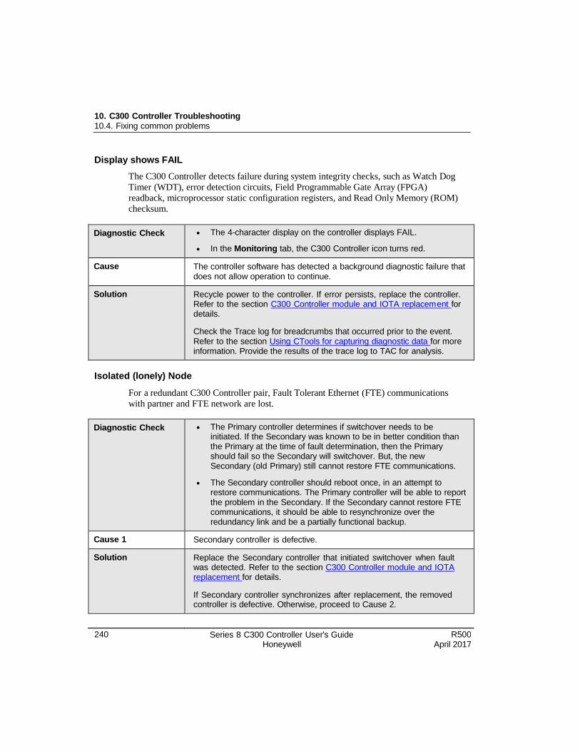
10. C300 Controller Troubleshooting 10.4. Fixing common problems
240 Series 8 C300 Controller User's Guide Honeywell
R500 April 2017
Display shows FAIL
The C300 Controller detects failure during system integrity checks, such as Watch Dog
Timer (WDT), error detection circuits, Field Programmable Gate Array (FPGA)
readback, microprocessor static configuration registers, and Read Only Memory (ROM)
checksum.
Diagnostic Check The 4-character display on the controller displays FAIL.
In the Monitoring tab, the C300 Controller icon turns red.
Cause The controller software has detected a background diagnostic failure that does not allow operation to continue.
Solution Recycle power to the controller. If error persists, replace the controller. Refer to the section C300 Controller module and IOTA replacem ent for details.
Check the Trace log for breadcrumbs that occurred prior to the event. Refer to the section Using CTools for capturing diagnostic data for more information. Provide the results of the trace log to TAC for analysis.
Isolated (lonely) Node
For a redundant C300 Controller pair, Fault Tolerant Ethernet (FTE) communications
with partner and FTE network are lost.
Diagnostic Check The Primary controller determines if switchover needs to be initiated. If the Secondary was known to be in better condition than the Primary at the time of fault determination, then the Primary should fail so the Secondary will switchover. But, the new Secondary (old Primary) still cannot restore FTE communications.
The Secondary controller should reboot once, in an attempt to restore communications. The Primary controller will be able to report the problem in the Secondary. If the Secondary cannot restore FTE communications, it should be able to resynchronize over the redundancy link and be a partially functional backup.
Cause 1 Secondary controller is defective.
Solution Replace the Secondary controller that initiated switchover when fault was detected. Refer to the section C300 Controller module and IOTA replacement for details.
If Secondary controller synchronizes after replacement, the removed controller is defective. Otherwise, proceed to Cause 2.
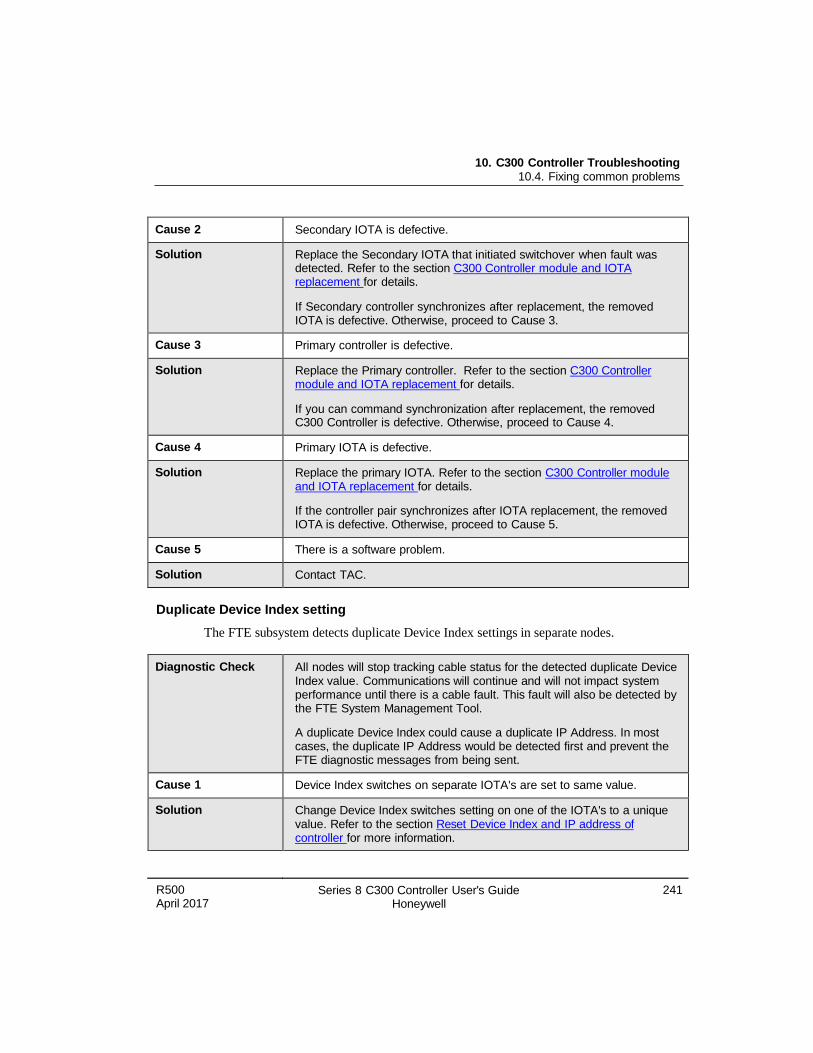
10. C300 Controller Troubleshooting 10.4. Fixing common problems
R500 April 2017
Series 8 C300 Controller User's Guide Honeywell
241
Cause 2 Secondary IOTA is defective.
Solution Replace the Secondary IOTA that initiated switchover when fault was detected. Refer to the section C300 Controller module and IOTA replacement for details.
If Secondary controller synchronizes after replacement, the removed IOTA is defective. Otherwise, proceed to Cause 3.
Cause 3 Primary controller is defective.
Solution Replace the Primary controller. Refer to the section C300 Controller module and IOTA replacement for details.
If you can command synchronization after replacement, the removed C300 Controller is defective. Otherwise, proceed to Cause 4.
Cause 4 Primary IOTA is defective.
Solution Replace the primary IOTA. Refer to the section C300 Controller module and IOTA replacement for details.
If the controller pair synchronizes after IOTA replacement, the removed IOTA is defective. Otherwise, proceed to Cause 5.
Cause 5 There is a software problem.
Solution Contact TAC.
Duplicate Device Index setting
The FTE subsystem detects duplicate Device Index settings in separate nodes.
Diagnostic Check All nodes will stop tracking cable status for the detected duplicate Device Index value. Communications will continue and will not impact system performance until there is a cable fault. This fault will also be detected by the FTE System Management Tool.
A duplicate Device Index could cause a duplicate IP Address. In most cases, the duplicate IP Address would be detected first and prevent the FTE diagnostic messages from being sent.
Cause 1 Device Index switches on separate IOTA's are set to same value.
Solution Change Device Index switches setting on one of the IOTA's to a unique value. Refer to the section Reset Device Index and IP address of controller for more information.
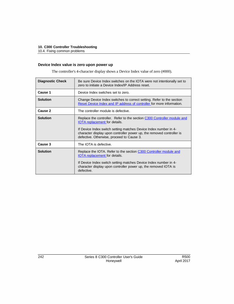
10. C300 Controller Troubleshooting 10.4. Fixing common problems
242 Series 8 C300 Controller User's Guide Honeywell
R500 April 2017
Device Index value is zero upon power up
The controller's 4-character display shows a Device Index value of zero (#000).
Diagnostic Check Be sure Device Index switches on the IOTA were not intentionally set to zero to initiate a Device Index/IP Address reset.
Cause 1 Device Index switches set to zero.
Solution Change Device Index switches to correct setting. Refer to the section Res et Device Index and IP address of controller for more information.
Cause 2 The controller module is defective.
Solution Replace the controller. Refer to the section C300 Controller module and IOTA replacement for details.
If Device Index switch setting matches Device Index number in 4- character display upon controller power up, the removed controller is defective. Otherwise, proceed to Cause 3.
Cause 3 The IOTA is defective.
Solution Replace the IOTA. Refer to the section C300 Controller module and IOTA replacement for details.
If Device Index switch setting matches Device Index number in 4- character display upon controller power up, the removed IOTA is defective.
R500 April 2017
Series 8 C300 Controller User's Guide Honeywell
243
10. C300 Controller Troubleshooting 10.5. C300 Controller soft failures
10.5 C300 Controller soft failures
Soft failures are indicated on the Soft Failures tab of the C300 block configuration form
shown in Figure 11.
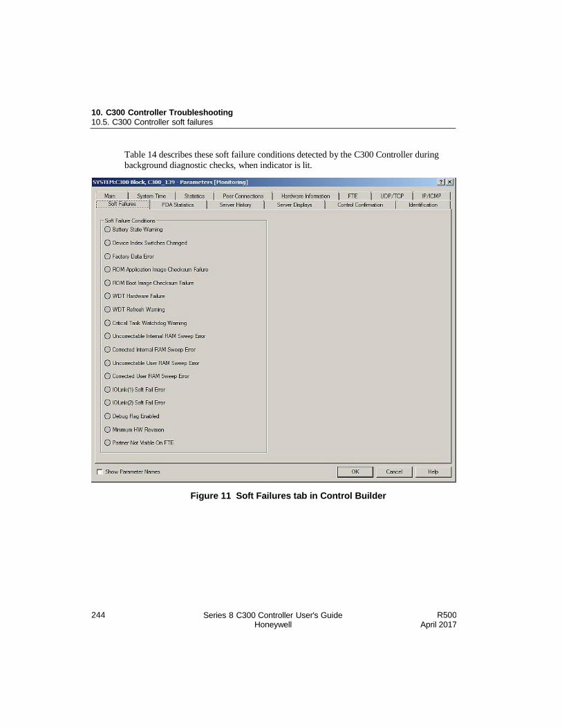
244 Series 8 C300 Controller User's Guide Honeywell
R500 April 2017
10. C300 Controller Troubleshooting 10.5. C300 Controller soft failures
Table 14 describes these soft failure conditions detected by the C300 Controller during
background diagnostic checks, when indicator is lit.
Figure 11 Soft Failures tab in Control Builder
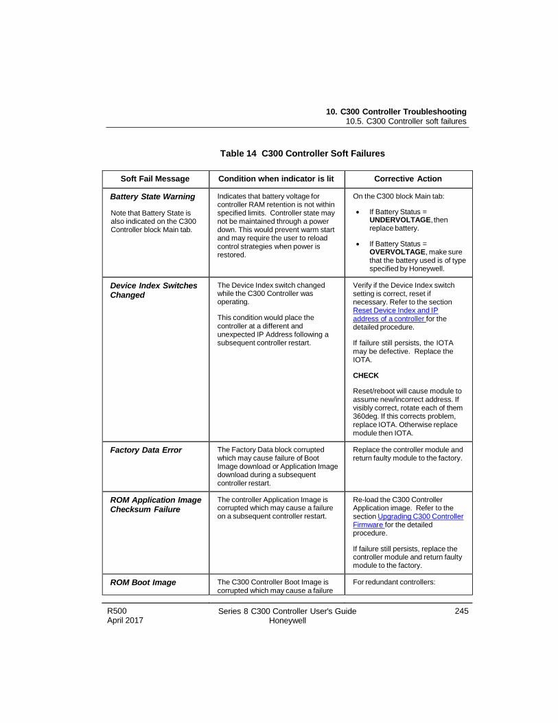
R500 April 2017
Series 8 C300 Controller User's Guide Honeywell
245
10. C300 Controller Troubleshooting 10.5. C300 Controller soft failures
Table 14 C300 Controller Soft Failures
Soft Fail Message Condition when indicator is lit Corrective Action
Battery State Warning
Note that Battery State is also indicated on the C300 Controller block Main tab.
Indicates that battery voltage for controller RAM retention is not within specified limits. Controller state may not be maintained through a power down. This would prevent warm start and may require the user to reload control strategies when power is restored.
On the C300 block Main tab:
If Battery Status = UNDERVOLTAGE, then replace battery.
If Battery Status = OVERVOLTAGE, make sure that the battery used is of type specified by Honeywell.
Device Index Switches Changed
The Device Index switch changed while the C300 Controller was operating.
This condition would place the controller at a different and unexpected IP Address following a subsequent controller restart.
Verify if the Device Index switch setting is correct, reset if necessary. Refer to the section Reset Device Index and IP address of a controller for the detailed procedure.
If failure still persists, the IOTA may be defective. Replace the IOTA.
CHECK
Reset/reboot will cause module to assume new/incorrect address. If visibly correct, rotate each of them 360deg. If this corrects problem, replace IOTA. Otherwise replace module then IOTA.
Factory Data Error The Factory Data block corrupted which may cause failure of Boot Image download or Application Image download during a subsequent controller restart.
Replace the controller module and return faulty module to the factory.
ROM Application Image Checksum Failure
The controller Application Image is corrupted which may cause a failure on a subsequent controller restart.
Re-load the C300 Controller Application image. Refer to the section Upgrading C300 Controller Firmwar e for the detailed procedure.
If failure still persists, replace the controller module and return faulty module to the factory.
ROM Boot Image The C300 Controller Boot Image is corrupted which may cause a failure
For redundant controllers:
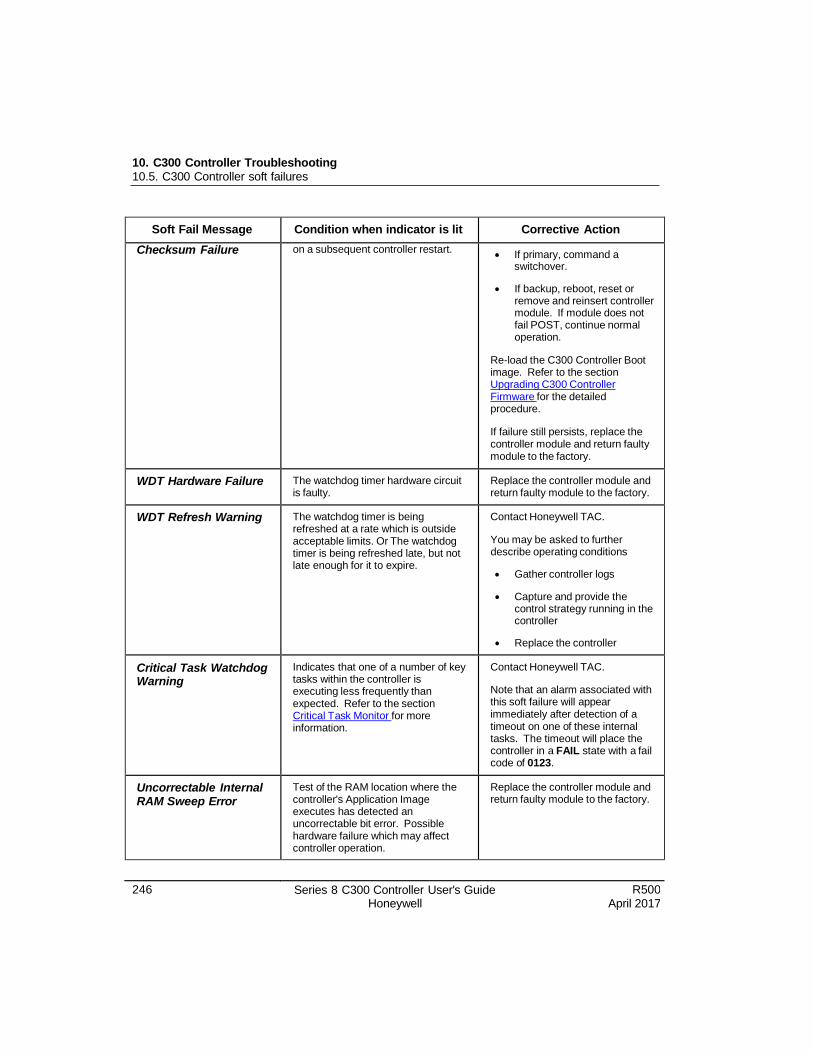
246 Series 8 C300 Controller User's Guide Honeywell
R500 April 2017
10. C300 Controller Troubleshooting 10.5. C300 Controller soft failures
Soft Fail Message Condition when indicator is lit Corrective Action
Checksum Failure on a subsequent controller restart. If primary, command a
switchover.
If backup, reboot, reset or remove and reinsert controller module. If module does not fail POST, continue normal operation.
Re-load the C300 Controller Boot image. Refer to the section Upgrading C300 Controller Firmware for the detailed procedure.
If failure still persists, replace the controller module and return faulty module to the factory.
WDT Hardware Failure The watchdog timer hardware circuit is faulty.
Replace the controller module and return faulty module to the factory.
WDT Refresh Warning The watchdog timer is being refreshed at a rate which is outside acceptable limits. Or The watchdog timer is being refreshed late, but not late enough for it to expire.
Contact Honeywell TAC.
You may be asked to further describe operating conditions
Gather controller logs
Capture and provide the control strategy running in the controller
Replace the controller
Critical Task Watchdog Warning
Indicates that one of a number of key tasks within the controller is executing less frequently than expected. Refer to the section Critical T ask Monitor for more information.
Contact Honeywell TAC.
Note that an alarm associated with this soft failure will appear immediately after detection of a timeout on one of these internal tasks. The timeout will place the controller in a FAIL state with a fail code of 0123.
Uncorrectable Internal RAM Sweep Error
Test of the RAM location where the controller's Application Image executes has detected an uncorrectable bit error. Possible hardware failure which may affect controller operation.
Replace the controller module and return faulty module to the factory.
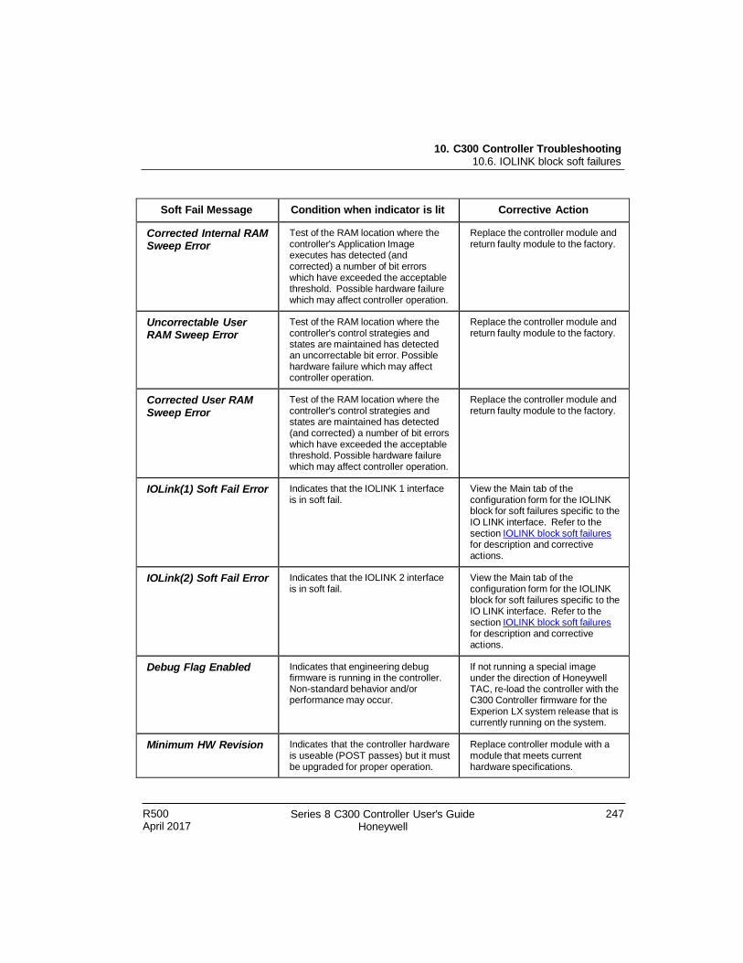
R500 April 2017
Series 8 C300 Controller User's Guide Honeywell
247
10. C300 Controller Troubleshooting 10.6. IOLINK block soft failures
Soft Fail Message Condition when indicator is lit Corrective Action
Corrected Internal RAM Sweep Error
Test of the RAM location where the controller's Application Image executes has detected (and corrected) a number of bit errors which have exceeded the acceptable threshold. Possible hardware failure which may affect controller operation.
Replace the controller module and return faulty module to the factory.
Uncorrectable User RAM Sweep Error
Test of the RAM location where the controller's control strategies and states are maintained has detected an uncorrectable bit error. Possible hardware failure which may affect controller operation.
Replace the controller module and return faulty module to the factory.
Corrected User RAM Sweep Error
Test of the RAM location where the controller's control strategies and states are maintained has detected (and corrected) a number of bit errors which have exceeded the acceptable threshold. Possible hardware failure which may affect controller operation.
Replace the controller module and return faulty module to the factory.
IOLink(1) Soft Fail Error Indicates that the IOLINK 1 interface is in soft fail.
View the Main tab of the configuration form for the IOLINK block for soft failures specific to the IO LINK interface. Refer to the section IOLINK block soft failures for description and corrective actions.
IOLink(2) Soft Fail Error Indicates that the IOLINK 2 interface is in soft fail.
View the Main tab of the configuration form for the IOLINK block for soft failures specific to the IO LINK interface. Refer to the section IOLINK block soft failures for description and corrective actions.
Debug Flag Enabled Indicates that engineering debug firmware is running in the controller. Non-standard behavior and/or performance may occur.
If not running a special image under the direction of Honeywell TAC, re-load the controller with the C300 Controller firmware for the Experion LX system release that is currently running on the system.
Minimum HW Revision Indicates that the controller hardware is useable (POST passes) but it must be upgraded for proper operation.
Replace controller module with a module that meets current hardware specifications.
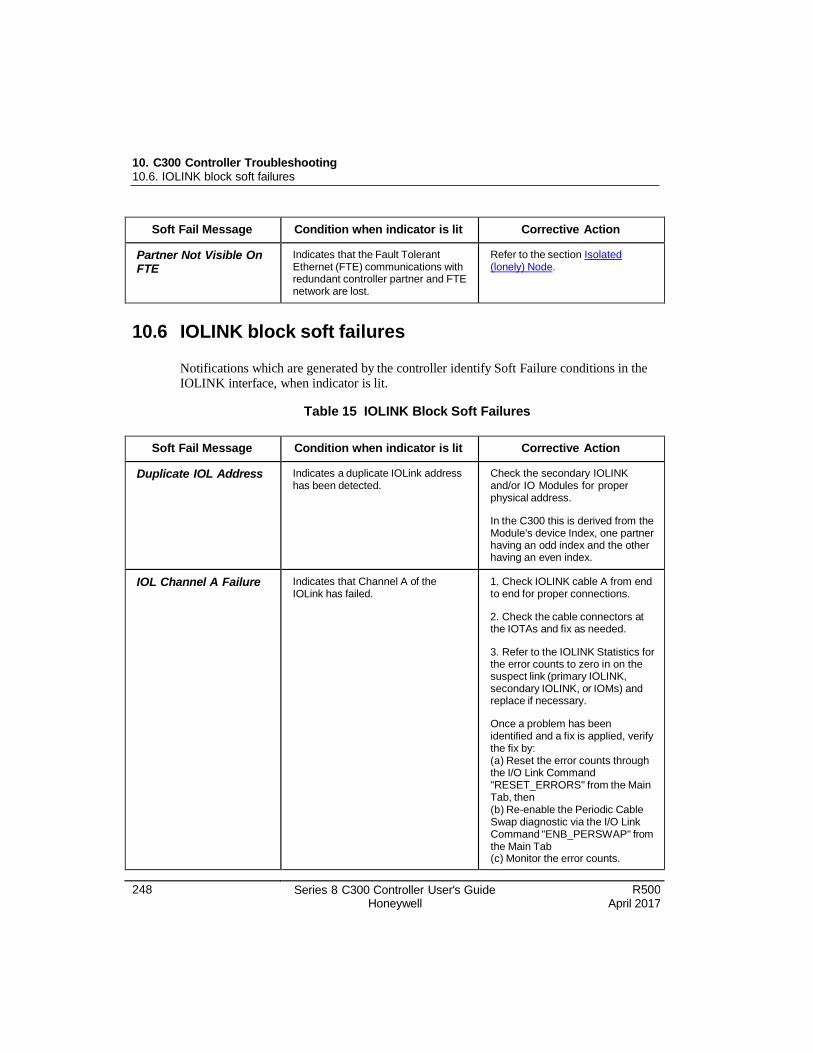
248 Series 8 C300 Controller User's Guide Honeywell
R500 April 2017
10. C300 Controller Troubleshooting 10.6. IOLINK block soft failures
Soft Fail Message Condition when indicator is lit Corrective Action
Partner Not Visible On FTE
Indicates that the Fault Tolerant Ethernet (FTE) communications with redundant controller partner and FTE network are lost.
Refer to the section Isolated (lonely) Node.
10.6 IOLINK block soft failures
Notifications which are generated by the controller identify Soft Failure conditions in the IOLINK interface, when indicator is lit.
Table 15 IOLINK Block Soft Failures
Soft Fail Message Condition when indicator is lit Corrective Action
Duplicate IOL Address Indicates a duplicate IOLink address has been detected.
Check the secondary IOLINK and/or IO Modules for proper physical address.
In the C300 this is derived from the Module's device Index, one partner having an odd index and the other having an even index.
IOL Channel A Failure Indicates that Channel A of the IOLink has failed.
1. Check IOLINK cable A from end to end for proper connections.
2. Check the cable connectors at the IOTAs and fix as needed.
3. Refer to the IOLINK Statistics for the error counts to zero in on the suspect link (primary IOLINK, secondary IOLINK, or IOMs) and replace if necessary.
Once a problem has been identified and a fix is applied, verify the fix by: (a) Reset the error counts through the I/O Link Command "RESET_ERRORS" from the Main Tab, then (b) Re-enable the Periodic Cable Swap diagnostic via the I/O Link Command "ENB_PERSWAP" from the Main Tab (c) Monitor the error counts.
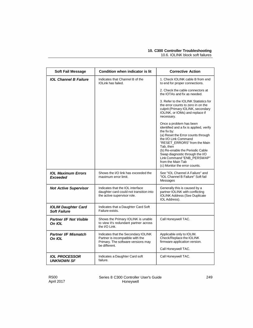
R500 April 2017
Series 8 C300 Controller User's Guide Honeywell
249
10. C300 Controller Troubleshooting 10.6. IOLINK block soft failures
Soft Fail Message Condition when indicator is lit Corrective Action
IOL Channel B Failure Indicates that Channel B of the IOLink has failed.
1. Check IOLINK cable B from end to end for proper connections.
2. Check the cable connectors at the IOTAs and fix as needed.
3. Refer to the IOLINK Statistics for the error counts to zero in on the culprit (Primary IOLINK, secondary IOLINK, or IOMs) and replace if necessary.
Once a problem has been identified and a fix is applied, verify the fix by: (a) Reset the Error counts through the I/O Link Command "RESET_ERRORS" from the Main Tab, then (b) Re-enable the Periodic Cable Swap diagnostic through the I/O Link Command "ENB_PERSWAP" from the Main Tab (c) Monitor the error counts.
IOL Maximum Errors Exceeded
Shows the I/O link has exceeded the maximum error limit.
See "IOL Channel A Failure" and "IOL Channel B Failure" Soft fail Messages
Not Active Supervisor Indicates that the IOL interface daughter card could not transition into the active supervisor role.
Generally this is caused by a partner IOLINK with conflicting IOLINK Address (See Duplicate IOL Address).
IOLIM Daughter Card Soft Failure
Indicates that a Daughter Card Soft Failure exists.
Partner I/F Not Visible On IOL
Shows the Primary IOLINK is unable to view it's redundant partner across the I/O Link.
Call Honeywell TAC.
Partner I/F Mismatch On IOL
Indicates that the Secondary IOLINK Partner is incompatible with the Primary. The software versions may be different.
Applicable only to IOLIM. Check/Replace the IOLINK firmware application version.
Call Honeywell TAC.
IOL PROCESSOR UNKNOWN SF
Indicates a Daughter Card soft failure.
Call Honeywell TAC.
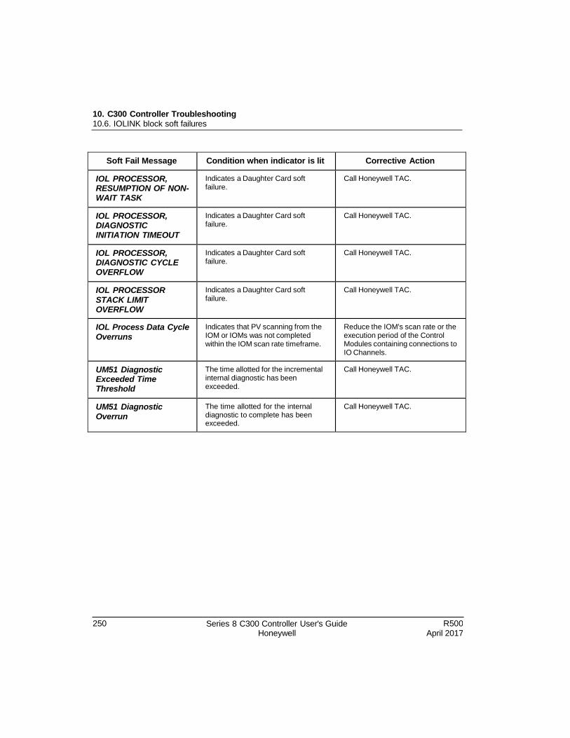
10. C300 Controller Troubleshooting 10.6. IOLINK block soft failures
250 Series 8 C300 Controller User's Guide Honeywell
R500 April 2017
Soft Fail Message Condition when indicator is lit Corrective Action
IOL PROCESSOR, RESUMPTION OF NON- WAIT TASK
Indicates a Daughter Card soft failure.
Call Honeywell TAC.
IOL PROCESSOR, DIAGNOSTIC INITIATION TIMEOUT
Indicates a Daughter Card soft failure.
Call Honeywell TAC.
IOL PROCESSOR, DIAGNOSTIC CYCLE OVERFLOW
Indicates a Daughter Card soft failure.
Call Honeywell TAC.
IOL PROCESSOR STACK LIMIT OVERFLOW
Indicates a Daughter Card soft failure.
Call Honeywell TAC.
IOL Process Data Cycle Overruns
Indicates that PV scanning from the IOM or IOMs was not completed within the IOM scan rate timeframe.
Reduce the IOM's scan rate or the execution period of the Control Modules containing connections to IO Channels.
UM51 Diagnostic Exceeded Time Threshold
The time allotted for the incremental internal diagnostic has been exceeded.
Call Honeywell TAC.
UM51 Diagnostic Overrun
The time allotted for the internal diagnostic to complete has been exceeded.
Call Honeywell TAC.
R500 April 2017
Series 8 C300 Controller User's Guide Honeywell
251
10. C300 Controller Troubleshooting 10.7. Additional status and fault messages
10.7 Additional status and fault messages
Redundancy-related notifications
Messages generated by the controller related to redundancy status and redundancy faults
are listed in the Redundancy section in Table 13.
10.8 Online diagnostics
Hardware diagnostics are executed within the controller during normal operations. Some
diagnostics execute frequently, but all diagnostics are designed to complete within eight
hours (the Diagnostic Test Interval). Once the controller's Power-On Self Test and
startup routines are completed successfully, these diagnostics execute to detect any of an
array of faults that might cause degradation in controller operation.
When a fault is detected by the controller, it identifies and reports the fault to the system
and acts to maintain control and view through a switchover, if required (in the case of
synchronized redundant controller pairs). Various actions are taken by the controller
depending upon the severity or type of fault (Fault classification). Even though some of
these detected faults do not cause a failure or an action (such as a switchover) by the
controller, the faults are reported to alert operators of a potential failure in the future if
not corrected.
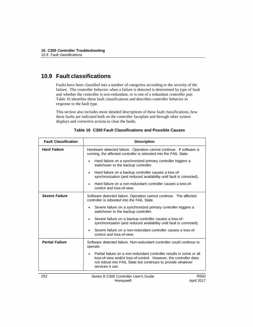
10. C300 Controller Troubleshooting 10.9. Fault classifications
252 Series 8 C300 Controller User's Guide Honeywell
R500 April 2017
10.9 Fault classifications
Faults have been classified into a number of categories according to the severity of the
failure. The controller behavior when a failure is detected is determined by type of fault
and whether the controller is non-redundant, or is one of a redundant controller pair.
Table 16 identifies these fault classifications and describes controller behavior in
response to the fault type.
This section also includes more detailed descriptions of these fault classifications, how
these faults are indicated both on the controller faceplate and through other system
displays and corrective actions to clear the faults.
Table 16 C300 Fault Classifications and Possible Causes
Fault Classification Description
Hard Failure Hardware detected failure. Operation cannot continue. If software is running, the affected controller is rebooted into the FAIL State.
Hard failure on a synchronized primary controller triggers a switchover to the backup controller.
Hard failure on a backup controller causes a loss-of- synchronization (and reduced availability until fault is corrected).
Hard failure on a non-redundant controller causes a loss-of- control and loss-of-view.
Severe Failure Software detected failure. Operation cannot continue. The affected controller is rebooted into the FAIL State.
Severe failure on a synchronized primary controller triggers a switchover to the backup controller.
Severe failure on a backup controller causes a loss-of- synchronization (and reduced availability until fault is corrected).
Severe failure on a non-redundant controller causes a loss-of- control and loss-of-view.
Partial Failure Software detected failure. Non-redundant controller could continue to operate.
Partial failure on a non-redundant controller results in some or all loss-of-view and/or loss-of-control. However, the controller does not reboot into FAIL State but continues to provide whatever services it can.
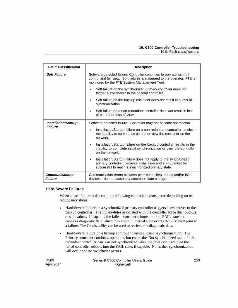
R500 April 2017
Series 8 C300 Controller User's Guide Honeywell
253
10. C300 Controller Troubleshooting 10.9. Fault classifications
Fault Classification Description
Soft Failure Software detected failure. Controller continues to operate with full control and full view. Soft failures are alarmed to the operator. FTE is monitored by the FTE System Management Tool.
Soft failure on the synchronized primary controller does not trigger a switchover to the backup controller.
Soft failure on the backup controller does not result in a loss-of-
synchronization.
Soft failure on a non-redundant controller does not result in loss- of-control or loss-of-view.
Installation/Startup Failure
Software detected failure. Controller may not become operational.
Installation/Startup failure on a non-redundant controller results in the inability to commence control or view the controller on the network.
Installation/Startup failure on the backup controller results in the inability to complete initial synchronization or view the controller on the network.
Installation/Startup failure does not apply to the synchronized primary controller, because installation and startup must be successful to reach a synchronized primary state.
Communications Failure
Communication errors between peer controllers, nodes and/or I/O devices - do not cause any controller state change.
Hard/Severe Failures
When a hard failure is detected, the following controller events occur depending on its
redundancy status:
Hard/Severe failure on a synchronized primary controller triggers a switchover to the
backup controller. The I/O modules associated with the controller force their outputs
to safe values. If capable, the failed controller reboots into the FAIL state and
captures diagnostic data which may contain internal state events that occurred prior to
a failure. The Ctools utility can be used to retrieve the diagnostic data.
Hard/Severe failure on a backup controller causes a loss-of-synchronization. The
Primary controller continues operation, but enters the 'Not synchronized' state. If the
redundant controller pair was not synchronized when the fault occurred, then the
failed controller reboots into the FAIL state, if capable. No further synchronization
will occur and no switchover occurs.
254 Series 8 C300 Controller User's Guide Honeywell
R500 April 2017
10. C300 Controller Troubleshooting 10.9. Fault classifications
Hard/Severe failure on a non-redundant controller causes a loss-of-control and loss-
of-view. The I/O modules associated with the controller force their outputs to safe
values. If capable, the failed controller reboots into the FAIL state and captures
diagnostic data which may contain internal state events that occurred prior to a
failure. The CTools utility can be used to retrieve the diagnostic data.
Alarm display and function block detail display
Usually a hard or severe failure results in a communication failure. Calling up the Alarm
Detail Display in Station or the Controller Block Detail Display will show this failure.
Control Builder indications and error log
Using Control Builder, you can view the current state of controllers in the system. In the
Control Builder monitor tab, a hard failure in the controller is denoted by a red controller
icon indicating no communication. Refer to the Control Builder icon descriptions for a
complete listing of the C300 Controller icons that may appear in Control Builder.
The Errlog_n.txt log provides a running list of Control Builder detected errors in
chronological order. The n represents any number that is assigned to the most recent log.
To check the log, navigate to this file location on the server: C:\Documents and Settings\All
Users\Application Data\Honeywell\Experion\Errlog_n.txt.
Soft Failures
Soft Failures are detected also through execution of the Controller's online (background)
diagnostics. Soft failures do not cause change in the state of the controller's execution
environments (CEEC300 or IOLINK blocks). There is no loss of control or loss of view
when a controller detects a soft failure.
In a redundant controller pair, a soft failure in a synchronized primary controller does not
cause a switchover to the backup controller. A soft failure in the backup controller does
not result in a loss of synchronization, if the redundant controller pair is synchronized.
Alarm displays and Control Builder forms
Soft failures are reported in the Alarm Summary and the C300 Controller Function Block
Detail displays in Station. In Control Builder, soft failure status is indicated on:
The Main tab of the configuration form for the associated C300 Controller block
(Soft Failures Present).
The Soft Failures tab of the controller block configuration form includes a list of the
possible soft failure conditions as shown in Figure 11. (A listing of the Soft Failures
with descriptions and corrective action is in
R500 April 2017
Series 8 C300 Controller User's Guide Honeywell
255
10. C300 Controller Troubleshooting 10.9. Fault classifications
Table 14.) An indicator next to each condition shows when the soft failure condition
is present.
The Control Builder monitor tab, soft failure in the controller is denoted by a controller icon with a small red circle with an 'x' inside the circle.
Soft Failure alarm return to normal
The alarm will return to normal once the on-line diagnostics detect that the soft failure
condition has been corrected. Note that on-line diagnostics run on a cycle and hence it
may take a period of time for the controller to perform the subsequent diagnostic check
for the condition, notice the change and then record it.
In some cases, online diagnostics may continue to assert the soft failure condition even
when it appears to have been corrected. This may happen when one occurrence of the
soft failure is considered sufficient to require action that requires replacement of
hardware. When the controller hardware is replaced, the alarm will return to normal
once the C300 Controller function block is deleted and reloaded.
Installation-Startup Failures
A fault that is detected during the C300 Controller's startup or Power-On Self Test
(POST) may prevent the controller from entering an operational state. The C300
Controller module executes a boot program and POST automatically when power is
applied to the controller module. These tests, verify the presence and integrity of the
controller module hardware. Refer to the section C300 Controller startup for more details
on startup and POST. Also, refer the section Communication and system time
startup fault scenarios for details on abnormal startup conditions and corrective actions to
clear them.
If a fault is detected during POST, the controller halts and shows the number of the test
that the controller was performing when it detected the fault on the faceplate display,
(Tnnn). Reset the controller by shorting the two RESET contacts on the controller
IOTA. If the fault persists, replace the controller module since a hardware failure is
indicated. Refer to the section C300 Controller module and IOTA replacement for
details.
A redundant controller that fails during startup or POST will not begin control or join the
FTE network. A backup controller that fails during startup or POST will not complete
initial synchronization with its primary or join the FTE network.
Hardware Watchdog Timer Expired
The watchdog timer in the controller employs an independent hardware circuit to ensure
that the controller and its connected I/O devices are brought to a safe state in case the
256 Series 8 C300 Controller User's Guide Honeywell
R500 April 2017
10. C300 Controller Troubleshooting 10.10. Communication and system time faults during startup
controller software becomes corrupted or stops executing. If a fault arises in the
hardware watchdog timer circuit, the controller would not be protected from corrupt
software execution. Therefore, a run-time diagnostic check verifies the watchdog timer
hardware integrity. If a fault is detected in the watchdog timer hardware circuit, a soft
failure condition occurs. Refer to the Hardware Watch dog Timer for more information.
The failed controller module does not contain any diagnostic data, although the
redundant partner module may contain some useful information.
Communications Failure
The FTE Status Server and FTE Auxiliary display includes detailed information on FTE
links monitored by the FTE Provider. Refer to the Fault Tolerant Ethernet Status Display User's Guide for more details.
10.10 Communication and system time faults during startup
The tables in this section help to provide guidance for determining the cause of abnormal startup conditions in the C300 Controller. These conditions may occur when the
controller
Cannot establish normal communication on the FTE network
Cannot obtain its network address from the system's BootP Server
Cannot obtain system time from the time source configured for the domain in which
it resides,
Finds that CDA services are not available.
Various indications on the controller's faceplate display or the state of the Control
Builder icon that represents the C300 Controller (if the controller had been loaded
previously) are described that point to an abnormal condition.
There are six tables that detail the abnormal conditions for both redundant and non-
redundant controller configurations and whether or not the controller memory has been
retained through the battery backup.
Corrective actions for resolving these conditions are found in the below mentioned
tables, (refer the Notes).
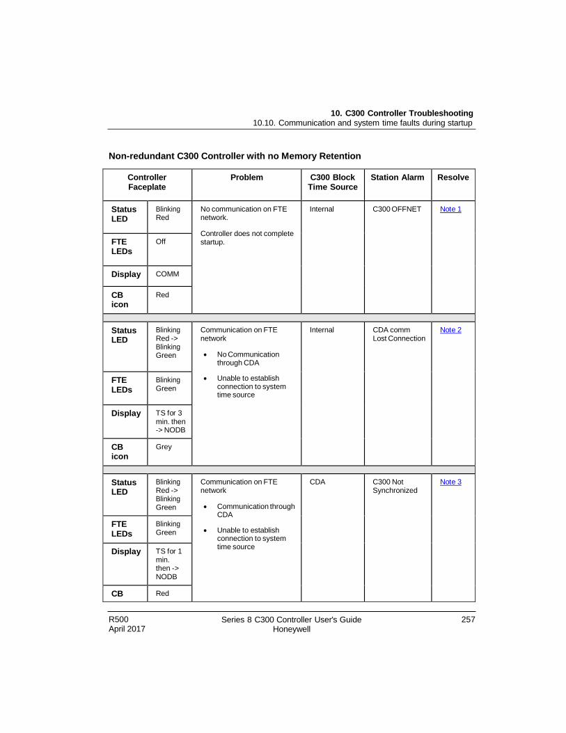
R500 April 2017
Series 8 C300 Controller User's Guide Honeywell
257
10. C300 Controller Troubleshooting 10.10. Communication and system time faults during startup
Non-redundant C300 Controller with no Memory Retention
Controller Faceplate
Problem C300 Block Time Source
Station Alarm Resolve
Status LED
Blinking Red
No communication on FTE network.
Controller does not complete startup.
Internal C300 OFFNET Not e 1
FTE LEDs
Off
Display COMM
CB icon
Red
Status LED
Blinking Red -> Blinking Green
Communication on FTE network
No Communication through CDA
Unable to establish connection to system time source
Internal CDA comm Lost Connection
Not e 2
FTE LEDs
Blinking Green
Display TS for 3 min. then -> NODB
CB icon
Grey
Status LED
Blinking Red -> Blinking Green
Communication on FTE network
Communication through CDA
Unable to establish connection to system time source
CDA C300 Not Synchronized
Not e 3
FTE LEDs
Blinking Green
Display TS for 1 min. then -> NODB
CB Red
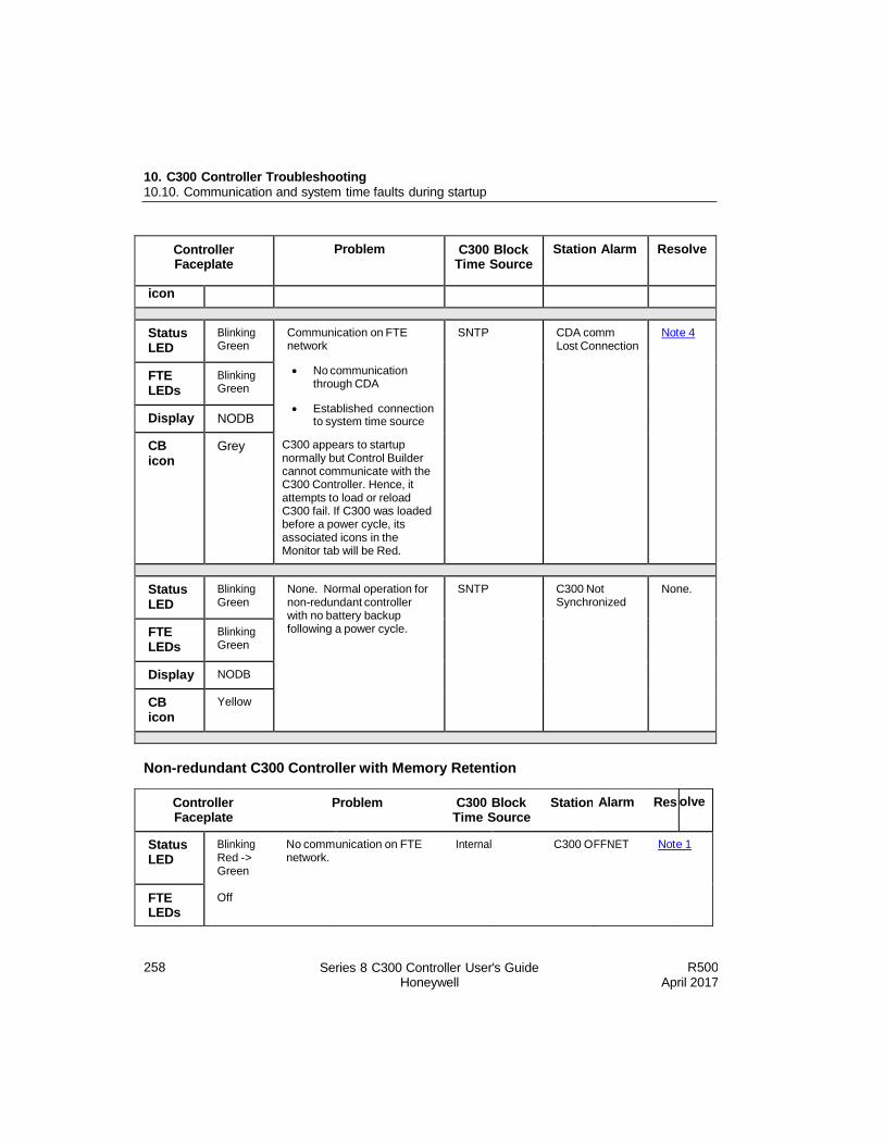
258 Series 8 C300 Controller User's Guide Honeywell
R500 April 2017
10. C300 Controller Troubleshooting 10.10. Communication and system time faults during startup
Controller Faceplate
Problem C300 Block Time Source
Station Alarm Resolve
icon
Status LED
Blinking Green
Communication on FTE network
No communication through CDA
Established connection to system time source
C300 appears to startup normally but Control Builder cannot communicate with the C300 Controller. Hence, it attempts to load or reload C300 fail. If C300 was loaded before a power cycle, its associated icons in the Monitor tab will be Red.
SNTP CDA comm Lost Connection
Not e 4
FTE LEDs
Blinking Green
Display NODB
CB icon
Grey
Status LED
Blinking Green
None. Normal operation for non-redundant controller with no battery backup following a power cycle.
SNTP C300 Not Synchronized
None.
FTE LEDs
Blinking Green
Display NODB
CB icon
Yellow
Non-redundant C300 Controller with Memory Retention
olve Controller Problem C300 Block Station Faceplate Time Source
Alarm Res
Status LED
Blinking No comm Red -> network. Green
unication on FTE Internal C300 O FFNET Not e 1
FTE LEDs
Off
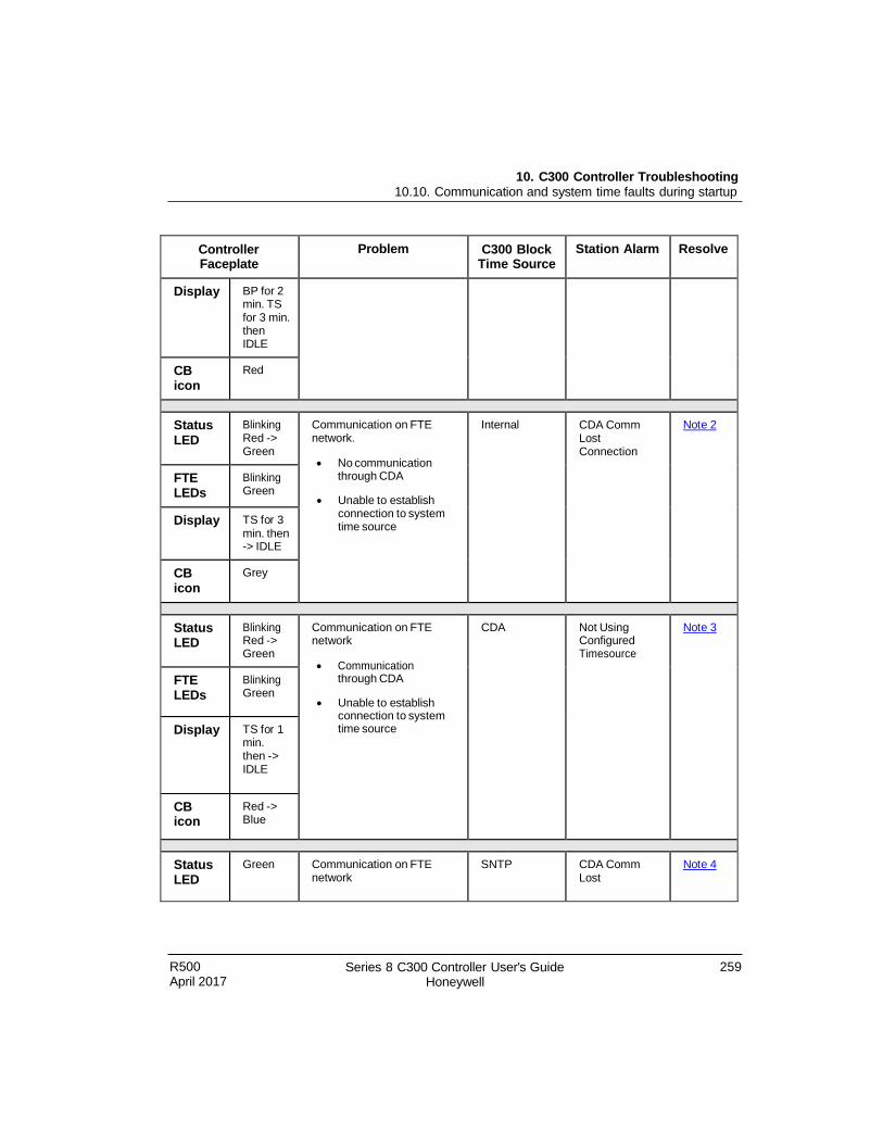
R500 April 2017
Series 8 C300 Controller User's Guide Honeywell
259
10. C300 Controller Troubleshooting 10.10. Communication and system time faults during startup
Controller Faceplate
Problem C300 Block Time Source
Station Alarm Resolve
Display BP for 2 min. TS for 3 min. then IDLE
CB icon
Red
Status LED
Blinking Red -> Green
Communication on FTE network.
No communication through CDA
Unable to establish connection to system time source
Internal CDA Comm Lost Connection
Not e 2
FTE LEDs
Blinking Green
Display TS for 3 min. then -> IDLE
CB icon
Grey
Status LED
Blinking Red -> Green
Communication on FTE network
Communication through CDA
Unable to establish connection to system time source
CDA Not Using Configured Timesource
Not e 3
FTE LEDs
Blinking Green
Display TS for 1 min. then -> IDLE
CB icon
Red -> Blue
Status LED
Green Communication on FTE network
SNTP CDA Comm Lost
Not e 4
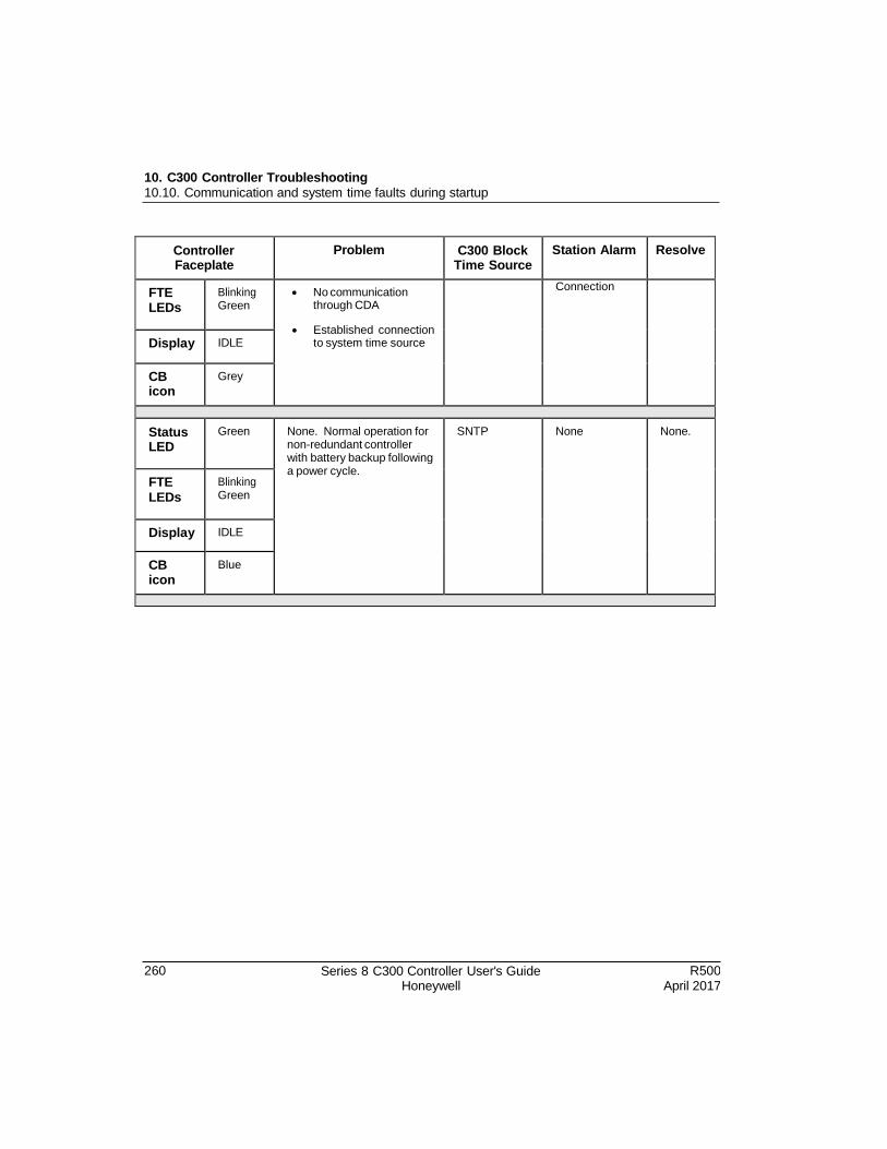
10. C300 Controller Troubleshooting 10.10. Communication and system time faults during startup
260 Series 8 C300 Controller User's Guide Honeywell
R500 April 2017
Controller Faceplate
Problem C300 Block Time Source
Station Alarm Resolve
FTE LEDs
Blinking Green
No communication through CDA
Established connection to system time source
Connection
Display IDLE
CB icon
Grey
Status LED
Green None. Normal operation for non-redundant controller with battery backup following a power cycle.
SNTP None None.
FTE LEDs
Blinking Green
Display IDLE
CB icon
Blue
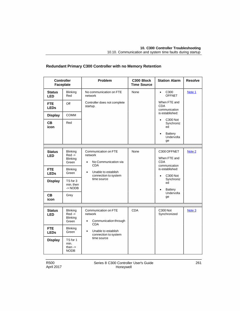
10. C300 Controller Troubleshooting 10.10. Communication and system time faults during startup
R500 April 2017
Series 8 C300 Controller User's Guide Honeywell
261
Redundant Primary C300 Controller with no Memory Retention
Controller Faceplate
Problem C300 Block Time Source
Station Alarm Resolve
Status LED
Blinking Red
No communication on FTE network
Controller does not complete startup.
None C300 OFFNET
When FTE and CDA communication is established:
C300 Not Synchroniz ed
Battery Undervolta ge
Not e 1
FTE LEDs
Off
Display COMM
CB icon
Red
Status LED
Blinking Red -> Blinking Green
Communication on FTE network
No Communication via CDA
Unable to establish connection to system time source
None C300 OFFNET
When FTE and CDA
communication is established:
C300 Not Synchroniz ed
Battery Undervolta ge
Not e 2
FTE LEDs
Blinking Green
Display TS for 3 min. then -> NODB
CB icon
Grey
Status LED
Blinking Red -> Blinking Green
Communication on FTE network
Communication through CDA
Unable to establish connection to system time source
CDA C300 Not Synchronized
Not e 3
FTE LEDs
Blinking Green
Display TS for 1 min. then -> NODB
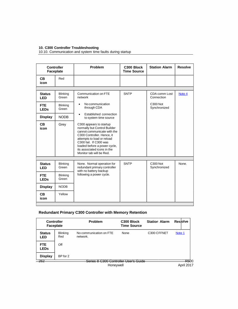
10. C300 Controller Troubleshooting 10.10. Communication and system time faults during startup
262 Series 8 C300 Controller User's Guide Honeywell
R500 April 2017
Controller Faceplate
Problem C300 Block Time Source
Station Alarm Resolve
CB icon
Red
Status LED
Blinking Green
Communication on FTE network
No communication through CDA
Established connection to system time source
C300 appears to startup normally but Control Builder cannot communicate with the C300 Controller. Hence, it attempts to load or reload C300 fail. If C300 was loaded before a power cycle, its associated icons in the Monitor tab will be Red.
SNTP CDA comm Lost Connection
C300 Not Synchronized
Not e 4
FTE LEDs
Blinking Green
Display NODB
CB icon
Grey
Status LED
Blinking Green
None. Normal operation for redundant primary controller with no battery backup following a power cycle.
SNTP C300 Not Synchronized
None.
FTE LEDs
Blinking Green
Display NODB
CB icon
Yellow
Redundant Primary C300 Controller with Memory Retention
olve
Controller Problem C300 Block Station Faceplate Time Source
Alarm Res
Status LED
Blinking No comm Red network.
unication on FTE None C300 O FFNET Not e 1
FTE LEDs
Off
Display BP for 2

10. C300 Controller Troubleshooting 10.10. Communication and system time faults during startup
R500 April 2017
Series 8 C300 Controller User's Guide Honeywell
263
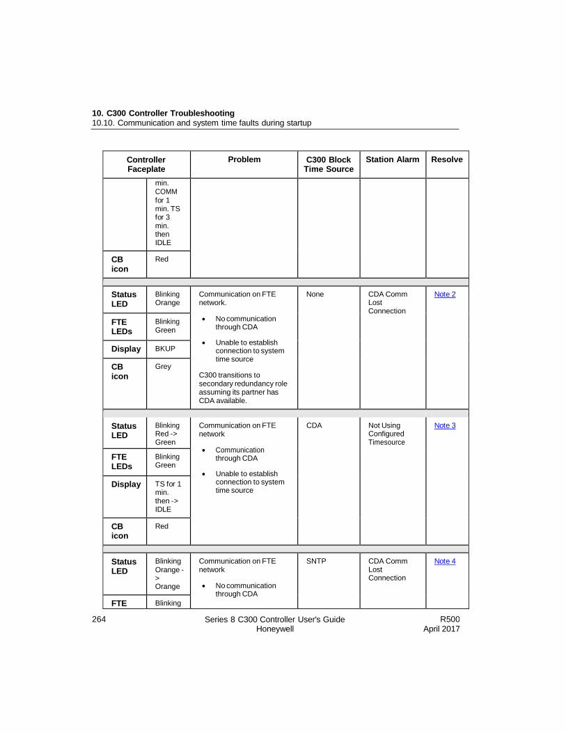
10. C300 Controller Troubleshooting 10.10. Communication and system time faults during startup
264 Series 8 C300 Controller User's Guide Honeywell
R500 April 2017
Controller Faceplate
Problem C300 Block Time Source
Station Alarm Resolve
min. COMM for 1 min. TS for 3 min. then IDLE
CB icon
Red
Status LED
Blinking Orange
Communication on FTE network.
No communication through CDA
Unable to establish connection to system time source
C300 transitions to secondary redundancy role assuming its partner has CDA available.
None CDA Comm Lost Connection
Not e 2
FTE LEDs
Blinking Green
Display BKUP
CB icon
Grey
Status LED
Blinking Red -> Green
Communication on FTE network
Communication through CDA
Unable to establish connection to system time source
CDA Not Using Configured Timesource
Not e 3
FTE LEDs
Blinking Green
Display TS for 1 min. then -> IDLE
CB icon
Red
Status LED
Blinking Orange - > Orange
Communication on FTE network
No communication through CDA
SNTP CDA Comm Lost Connection
Not e 4
FTE Blinking
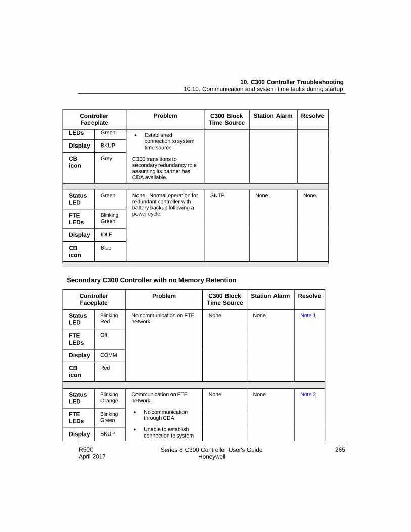
10. C300 Controller Troubleshooting 10.10. Communication and system time faults during startup
R500 April 2017
Series 8 C300 Controller User's Guide Honeywell
265
Controller Faceplate
Problem C300 Block Time Source
Station Alarm Resolve
LEDs Green Established
connection to system time source
C300 transitions to secondary redundancy role assuming its partner has CDA available.
Display BKUP
CB icon
Grey
Status LED
Green None. Normal operation for redundant controller with battery backup following a power cycle.
SNTP None None.
FTE LEDs
Blinking Green
Display IDLE
CB icon
Blue
Secondary C300 Controller with no Memory Retention
Controller Faceplate
Problem C300 Block Time Source
Station Alarm Resolve
Status LED
Blinking Red
No communication on FTE network.
None None Not e 1
FTE LEDs
Off
Display COMM
CB icon
Red
Status LED
Blinking Orange
Communication on FTE network.
No communication through CDA
Unable to establish connection to system
None None Not e 2
FTE LEDs
Blinking Green
Display BKUP

10. C300 Controller Troubleshooting 10.10. Communication and system time faults during startup
266 Series 8 C300 Controller User's Guide Honeywell
R500 April 2017
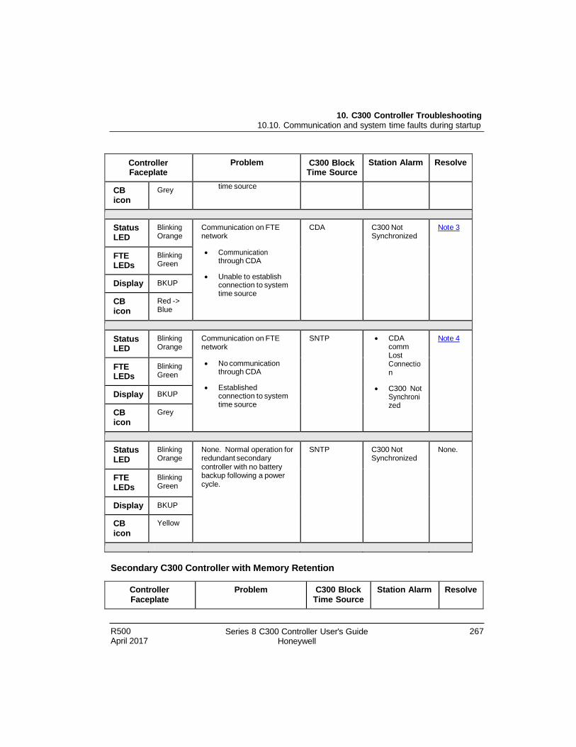
10. C300 Controller Troubleshooting 10.10. Communication and system time faults during startup
R500 April 2017
Series 8 C300 Controller User's Guide Honeywell
267
Controller Faceplate
Problem C300 Block Time Source
Station Alarm Resolve
CB icon
Grey time source
Status LED
Blinking Orange
Communication on FTE network
Communication through CDA
Unable to establish connection to system time source
CDA C300 Not Synchronized
Not e 3
FTE LEDs
Blinking Green
Display BKUP
CB icon
Red -> Blue
Status LED
Blinking Orange
Communication on FTE network
No communication through CDA
Established connection to system time source
SNTP CDA comm Lost Connectio n
C300 Not Synchroni zed
Not e 4
FTE LEDs
Blinking Green
Display BKUP
CB icon
Grey
Status LED
Blinking Orange
None. Normal operation for redundant secondary controller with no battery backup following a power cycle.
SNTP C300 Not Synchronized
None.
FTE LEDs
Blinking Green
Display BKUP
CB icon
Yellow
Secondary C300 Controller with Memory Retention
Controller Faceplate
Problem C300 Block Time Source
Station Alarm Resolve
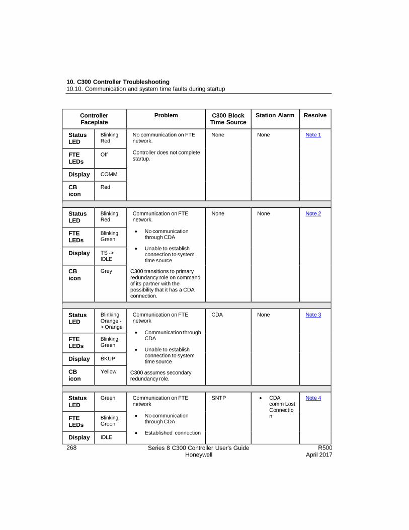
10. C300 Controller Troubleshooting 10.10. Communication and system time faults during startup
268 Series 8 C300 Controller User's Guide Honeywell
R500 April 2017
Controller Faceplate
Problem C300 Block Time Source
Station Alarm Resolve
Status LED
Blinking Red
No communication on FTE network.
Controller does not complete startup.
None None Not e 1
FTE LEDs
Off
Display COMM
CB icon
Red
Status LED
Blinking Red
Communication on FTE network.
No communication through CDA
Unable to establish connection to system time source
C300 transitions to primary redundancy role on command of its partner with the possibility that it has a CDA connection.
None None Not e 2
FTE LEDs
Blinking Green
Display TS -> IDLE
CB icon
Grey
Status LED
Blinking Orange - > Orange
Communication on FTE network
Communication through CDA
Unable to establish connection to system time source
C300 assumes secondary redundancy role.
CDA None Not e 3
FTE LEDs
Blinking Green
Display BKUP
CB icon
Yellow
Status LED
Green Communication on FTE network
No communication through CDA
Established connection
SNTP CDA comm Lost Connectio n
Not e 4
FTE LEDs
Blinking Green
Display IDLE
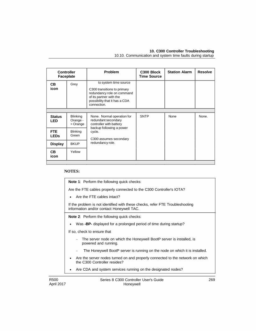
10. C300 Controller Troubleshooting 10.10. Communication and system time faults during startup
R500 April 2017
Series 8 C300 Controller User's Guide Honeywell
269
Controller Faceplate
Problem C300 Block Time Source
Station Alarm Resolve
CB icon
Grey to system time source
C300 transitions to primary redundancy role on command of its partner with the possibility that it has a CDA connection.
Status LED
Blinking Orange - > Orange
None. Normal operation for redundant secondary controller with battery backup following a power cycle.
C300 assumes secondary redundancy role.
SNTP None None.
FTE LEDs
Blinking Green
Display BKUP
CB icon
Yellow
NOTES:
Note 1: Perform the following quick checks:
Are the FTE cables properly connected to the C300 Controller's IOTA?
Are the FTE cables intact?
If the problem is not identified with these checks, refer FTE Troubleshooting information and/or contact Honeywell TAC.
Note 2: Perform the following quick checks:
Was -BP- displayed for a prolonged period of time during startup?
If so, check to ensure that
The server node on which the Honeywell BootP server is installed, is powered and running.
The Honeywell BootP server is running on the node on which it is installed.
Are the server nodes turned on and properly connected to the network on which the C300 Controller resides?
Are CDA and system services running on the designated nodes?
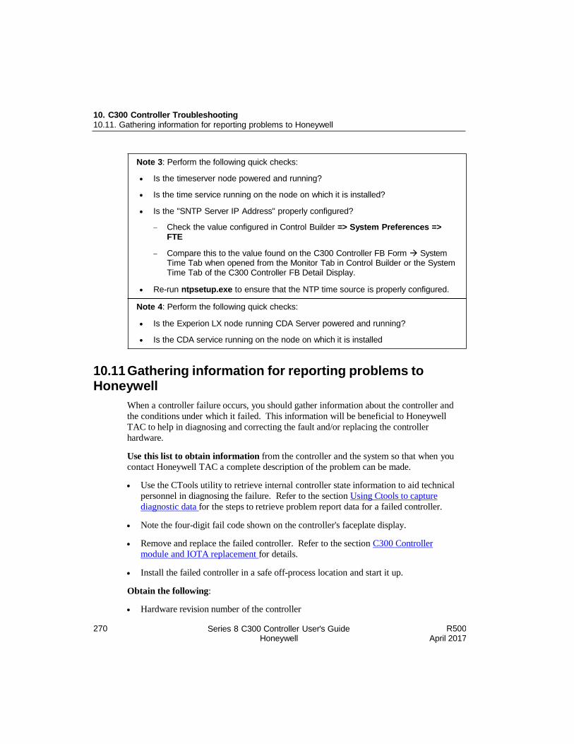
270 Series 8 C300 Controller User's Guide Honeywell
R500 April 2017
10. C300 Controller Troubleshooting 10.11. Gathering information for reporting problems to Honeywell
10.11 Gathering information for reporting problems to Honeywell
When a controller failure occurs, you should gather information about the controller and
the conditions under which it failed. This information will be beneficial to Honeywell
TAC to help in diagnosing and correcting the fault and/or replacing the controller
hardware.
Use this list to obtain information from the controller and the system so that when you
contact Honeywell TAC a complete description of the problem can be made.
Use the CTools utility to retrieve internal controller state information to aid technical
personnel in diagnosing the failure. Refer to the section Using Ctools to capture
diagnostic data for the steps to retrieve problem report data for a failed controller.
Note the four-digit fail code shown on the controller's faceplate display.
Remove and replace the failed controller. Refer to the section C300 Controller
module and IOTA replacement for details.
Install the failed controller in a safe off-process location and start it up.
Obtain the following:
Hardware revision number of the controller
Note 3: Perform the following quick checks:
Is the timeserver node powered and running?
Is the time service running on the node on which it is installed?
Is the "SNTP Server IP Address" properly configured?
Check the value configured in Control Builder => System Preferences => FTE
Compare this to the value found on the C300 Controller FB Form System Time Tab when opened from the Monitor Tab in Control Builder or the System Time Tab of the C300 Controller FB Detail Display.
Re-run ntpsetup.exe to ensure that the NTP time source is properly configured.
Note 4: Perform the following quick checks:
Is the Experion LX node running CDA Server powered and running?
Is the CDA service running on the node on which it is installed
R500 April 2017
Series 8 C300 Controller User's Guide Honeywell
271
10. C300 Controller Troubleshooting 10.11. Gathering information for reporting problems to Honeywell
Firmware revision, both the Boot image and Application image
The Experion LX System Release number in which the controller was operating
Additional information regarding the operating conditions of the controller and
sequence of events:
Was the controller operating in a redundant or non-redundant hardware
configuration?
What was the redundancy state of the controller at the time of the failure, if
redundant?
How many IOLinks did the controller support: 0, 1, or 2?
What I/O families were associated with the controller: Series 8?
If I/O was supported, were there any status indications given on the IOMs?
Any other status or fail indications on the controller's faceplate observed at the time
of the failure or following the event?
What were the Control Builder Monitor view indications at the time of the failure or
following the event?
What did the Alarm Status summary show for the time interval around the event?
Provide a detailed summary of the sequence of events leading up to the failure.
What operations preceded the event, such as: load, activate, change parameter, delete,
power cycle, synchronization, switchover, and so on?
10. C300 Controller Troubleshooting 10.12. Getting further assistance
270 Series 8 C300 Controller User's Guide Honeywell
R500 April 2017
10.12 Getting further assistance
Other troubleshooting sources
The following table lists other documents and sections that contain troubleshooting
information for other Experion LX subsystems.
Document/Section Comments
Control Builder Error Codes Reference Describes error codes generated from within Control Builder.
Guidelines for requesting support
If you cannot resolve a problem by using the above mentioned guides, you can request
support from your TAC. When requesting support, supply as many relevant details about
the problem by referring to Gathering information for reporting problems to Honeywell
section to obtain the problem-related information.

Honeywell Process Solutions 1860 W. Rose Garden Lane Phoenix, AZ 85027 USA