series ap500series ap500 single stage compact regulator for ultra high purity how to order ap5 02...
TRANSCRIPT

2
Operating Parameters
Delivery pressure
GasSource pressureProof pressure (Inlet)Burst pressureAmbient and operating temperatureCv
Leak rate
Across the seat leak Surface finishConnectionsSupply pressure effectInstallationInternal volumeMass
AP501mmA100 mm Hg absolute to 10 psig(-88 kPa to 0.07 MPa)
AP5010.5 to 10 psig
(0.0034 to 0.07 MPa)
AP5020.5 to 30 psig
(0.0034 to 0.2 MPa)
AP5061 to 60 psig
(0.007 to 0.4 MPa)Select compatible materials of construction for the gas
Vacuum to 150 psig (1.0 MPa)500 psig (3.4 MPa)1000 psig (6.9 MPa)
–40 to 160°F (–40 to 71 °C) (No freezing) ∗1)
0.062 x 10⁻¹¹ Pa·m3/sec
2 x 10⁻¹⁰ Pa·m3/sec ∗2)
4 x 10⁻⁹ Pa·m3/sec ∗2)
Ra max 15 µin. (0.4 µm) Option: 10 µin. (0.25 µm), 7 µin. (0.18 µm), 5 µin. (0.13 µm)Face seal, Tube weld
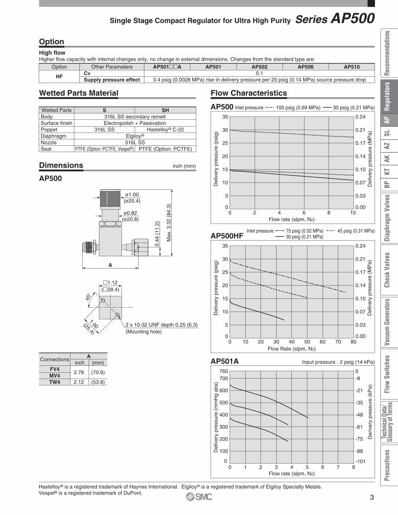
0.2 psig (0.0014 MPa) rise in delivery pressure per 20 psig (0.14 MPa) source pressure dropBottom mount
0.15 in3 (2.4 cm3)0.99 lbs (0.45 kg) ∗3)
AP5101 to 100 psig
(0.007 to 0.7 MPa)
Specifications
Porting Configuration (Top view)
e
qw
3PWG
w q
2PW
∗1) 14 to 194°F (–10 to 90 °C) for Vespel® seat.∗2) Tested with Helium gas inlet pressure 100 psig (0.7 MPa).∗3) Mass, including individual boxed weight, may vary depending on connections or options.
Inboard leakageOutboard leakage
Gauge port (Outlete)
No codeMV4FV4TW4V3L1
Connections or Pressure gauge ∗2)
psig/bar unit MPa unitNo gauge port1/4 inch face seal (Male)
1/4 inch face seal (Female)1/4 inch tube weld
Nopressuregauge
Withpressuregauge
-30in.Hg to 30psig-30in.Hg to 60psig-30in.Hg to 100psig
-0.1 to 0.2 MPa-0.1 to 0.4 MPa-0.1 to 0.7 MPa
Code
¡For UHP gas delivery¡Flow capacity Standard: to 15 slpm
HF (option): to 30 slpm¡Body material: 316L SS secondary remelt¡Hastelloy internals available for corrosion resistance¡Sub-atmospheric pressure delivery option
Series AP500
Single Stage Compact Regulator for Ultra High Purity
How to Order
AP5 S FV4 FV402 2PW
Surface finish
No codeMVX
Surface finish Ra max15 µin. (0.4 µm) Standard
10 µin. (0.25 µm)7 µin. (0.18 µm)5 µin. (0.13 µm)
Code
Ports
2PW3PWG
Ports2 ports3 ports
Code
Connections (Inletq, Outletw)
FV4MV4TW4
Connections1/4 inch face seal (Female)
1/4 inch face seal (Male)1/4 inch tube weld
Code
Range options∗1)
No codeA
SpecificationStandard
Sub-atmospheric
Code
∗1) Only available with AP501.
Port Numberq w e
Seat material
No codeTFVS
MaterialPCTFE (Standard)
PTFE ∗4)
Vespel® ∗5)
Code
∗4) PTFE recommended for applications suchas within a process tool.
∗5) Not available with SH material.
∗2) Refer to gauge guide (P.94) for gauge specifications.
No codeFIHF
SpecificationStandard
Friction dampener ∗6)
High flow ∗7)
Cv
0.06
0.1
Code
∗6) FI is friction dampener to slowresponse and reduce interactionwith MFC.
∗7) VS material not available with HFoption.
Pressure gauge unit∗3)
No codeMPA
Unitpsig/bar
MPa
Code
∗3) Pressure gauge unit MPa orpsig/bar selectable. Howeverunder Japanese regulation, onlyMPa is available in Japan.
316L SSsecondary
remelt
Material
S
SH
Body Poppet Diaphragm Nozzle
Hastelloy®
C-22
316L SSElgiloy® 316L SS
Code
Option
Delivery pressure
01
020610
Delivery pressure
0.5 to 30 psig (0.0034 to 0.2 MPa)1 to 60 psig (0.007 to 0.4 MPa)1 to 100 psig (0.007 to 0.7 MPa)
Code0.5 to 10 psig (0.0034 to 0.07 MPa)
Sub-atmospheric (A):100 mm Hg absolute to 10 psig
(-88 kPa to 0.07 MPa)
qIN wOUT eGauge port (Outlet)
2 x 10-32 UNF depth 0.25 (6.3)(Mounting hole)
45°
m1.12(m28.4)
0.44
(11.
2)
A
Max
.3.3
2(8
4.3)
ø0.82(ø20.8)
ø1.00(ø25.4)
1.00(25.4)
Option Other Parameters
HFCvSupply pressure effect
AP501mmA AP501 AP502 AP5060.1
0.4 psig (0.0028 MPa) rise in delivery pressure per 20 psig (0.14 MPa) source pressure drop
AP510
OptionHigh flowHigher flow capacity with internal changes only, no change in external dimensions. Changes from the standard type are:
Hastelloy® is a registered trademark of Haynes International. Elgiloy® is a registered trademark of Elgiloy Specialty Metals.Vespel® is a registered trademark of DuPont.
316L SS
PTFE (Option: PCTFE, Vespel®)
Hastelloy® C-22
PTFE (Option: PCTFE)
316L SS secondary remeltElectropolish + Passivation
Elgiloy®
316L SS
Wetted PartsBodySurface finishPoppetDiaphragmNozzleSeat
S SH
Wetted Parts Material
Connections
FV4MV4TW4
2.78
2.12
A
(70.6)
(53.8)
inch (mm)
Dimensions
AP500
Flow Characteristics
Single Stage Compact Regulator for Ultra High Purity Series AP500
inch (mm)
0
5
10
15
20
25
30
35
0 10 20 30 40 50 60 70 80Flow Rate (slpm, N2)
Del
iver
ypr
essu
re(p
sig)
0.00
0.03
0.07
0.10
0.14
0.17
0.21
0.24
Del
iver
ypr
essu
re(M
Pa)
0
5
10
15
20
25
30
35
0 2 4 6 8 10Flow rate (slpm, N2)
Del
iver
ypr
essu
re(p
sig)
0.00
0.03
0.07
0.10
0.14
0.17
0.21
0.24
Del
iver
ypr
essu
re(M
Pa)
0
100
200
300
400
500
600
700
0 1 2 3 4 5 6 7 8Flow rate (slpm, N2)
Del
iver
ypr
essu
re(m
mH
gab
s)
-101
-88
-75
-61
-48
-35
-21
-8
Der
iver
ypr
essu
re(k
Pa)
760 0
AP500HF75 psig (0.52 MPa)30 psig (0.21 MPa)
Inlet pressure: 45 psig (0.31 MPa)
AP500 100 psig (0.69 MPa)Inlet pressure: 30 psig (0.21 MPa)
AP501A Input pressure : 2 psig (14 kPa)
3
AZAK
KTBP
Diap
hrag
mVa
lves
Chec
kVa
lves
Vacu
umGe
nera
tors
Flow
Switc
hes
Tech
nica
lDat
a/Gl
ossa
ryof
Term
sPr
ecau
tions
SLAP
Reco
mm
enda
tions
Reg
ulat
ors

4
Operating Parameters
Delivery pressure
GasSource pressureProof pressure (Inlet)Burst pressureAmbient and operating temperatureCv
Leak rate
Across the seat leakSurface finishConnectionsBonnet portSupply pressure effectInstallationInternal volumeMass
AP10011 to 10 psig
(0.007 to 0.07 MPa)
AP10021 to 30 psig
(0.007 to 0.2 MPa)
AP10062 to 60 psig
(0.014 to 0.4 MPa)
AP10102 to 100 psig
(0.014 to 0.7 MPa)Select compatible materials of construction for the gas
5000 psig (34.5 MPa)10000 psig (69 MPa)
–40 to 160°F (–40 to 71°C) (No freezing) ∗2)
0.092 x 10⁻¹¹ Pa·m3/sec
2 x 10⁻¹⁰ Pa·m3/sec ∗3)
4 x 10⁻⁹ Pa·m3/sec ∗4)
Ra max 15 µin. (0.4 µm) Option: 10 µin. (0.25 µm), 7 µin. (0.18 µm), 5 µin. (0.13 µm)Face seal, Tube weld
NPT 1/8 inch ∗5)
0.38 psig (0.0026 MPa) rise in delivery pressure per 100 psig (0.7 MPa) source pressure dropBottom mount (Option: panel mount)
0.49 in3 (8 cm3)2.76 lbs (1.25 kg) ∗6)
AP10155 to 150 psig
(0.034 to 1.0 MPa)
∗1) Max 300 psig (2.1 MPa) for PTFE seat.∗2) 14 to 194°F (–10 to 90°C) for Vespel® seat.∗3) Tested with Helium gas inlet pressure 1500 psig (10.5 MPa).
Specifications
Porting Configuration
3PW
w q
r
2PW
w q
4PW
w q
r e
Vacuum to 3500 psig (24.1 MPa) ∗1)
∗4) Tested with Helium gas inlet pressure 1000 psig (7 MPa).∗5) On panel mount option, bonnet port is not threaded.∗6) Mass, including individual boxed weight, may vary depending on connections or options.
Inboard leakageOutboard leakage
Vacuum to 300 psig (2.1MPa)
Bonnet option
No codeP
BonnetStandard
Panel installation ∗6)
Code
¡For UHP gas delivery¡High inlet pressure type: Max. 3500 psig (24.1 MPa)¡Flow capacity Standard: to 30 slpm
HF (option): to 120 slpm¡Body material: 316L SS secondary remelt¡Hastelloy internals available for corrosion resistance
Series AP1000
Single Stage Regulator for Ultra High Purity
∗6) Panel mounting hole: dia 1.56inch (39.6 mm).
Pressure gauge unit ∗2)
No codeMPA
Unitpsig/bar
MPa
Code
∗2) Pressure gauge unit MPa or psig/barselectable. However under Japaneseregulation, only MPa is available in Japan.
How to Order
AP10 S FV4 FV401 2PW
Surface finish
No codeMVX
Surface finish Ra max15 µin. (0.4 µm) Standard
10 µin. (0.25 µm)7 µin. (0.18 µm)5 µin. (0.13 µm)
Code Ports
2PW3PW4PW
Ports2 ports3 ports4 ports
Code
Connections (Inletq, Outletw)
Seat material
No codeVSTF
MaterialPCTFE (Standard)
Vespel® ∗3)
PTFE ∗4) ∗5)
Code
∗3) Not available with SHP, SH, Hmaterials.
∗4) PTFE recommended for applications such as within a process tool.
∗5) Source pressure rating is limited to 300 psig (2.1 MPa) or less.
Port Numberq w e r
Delivery pressure
0102061015
Delivery pressure1 to 10 psig (0.007 to 0.07 MPa)1 to 30 psig (0.007 to 0.2 MPa)2 to 60 psig (0.014 to 0.4 MPa)2 to 100 psig (0.014 to 0.7 MPa)5 to 150 psig (0.034 to 1.0 MPa)
Code
Gauge port (Inlete, Outletr)
No code
0
V3L1H241040
No gauge port
-30 in.Hg to 30 psig-30 in.Hg to 60 psig-30 in.Hg to 100 psig-30 in.Hg to 160 psig
0 to 200 psig0 to 400 psig0 to 1000 psig0 to 4000 psig
-0.1 to 0.2 MPa-0.1 to 0.4 MPa-0.1 to 0.7 MPa-0.1 to 1.1 MPa0 to 1.4 MPa0 to 3 MPa0 to 7 MPa0 to 28 MPa
Pressure gauge ∗1)
psig/bar unit MPa unit
No pressure gauge(Connections: 1/4 inch face seal male)
Code
∗1) Refer to gauge guide (P.94) for gauge specifications.
qIN wOUT eGauge port (Inlet) rGauge port (Outlet)
2PW3PW3PW4PW
AP1001Se
1
w
FV4FV4FV4FV4
q
FV4FV4FV4FV4
r
0V3V3
MPAMPA
Sample Order NumberPort
Option
No codeHF
SpecificationStandard (Cv: 0.09)High flow (Cv: 0.15)
Code
Material
Hastelloy®
C-22
Nozzle
316L SS
Diaphragm316L SS
Hastelloy®
C-22
Poppet316L SS
Hastelloy®
C-22
316L SSsecondary
remelt
Body
Hastelloy®
C-22
SSHPSH
H
Code
FV4MV4TW4FV6MV6TW6
Connections1/4 inch face seal (Female)
1/4 inch face seal (Male)1/4 inch tube weld
3/8 inch face seal (Female) 3/8 inch face seal (Male)
3/8 inch tube weld
Code
Low to intermediate flow

Connections A
FV4MV4TW4FV6MV6TW6
(94.0)
(75.2)
(119.4)
(75.2)
3.70
2.96
4.70
2.96
(mm)inch
ø1.5 (ø38.1)
ø2.25 (ø57.2)
ø2.00 (ø50.8)
ø2.12 (ø53.8)
0.69
(17.
5)M
ax.5
.6(1
42.2
)
A
0.88 (22.4)
2 x 10-32 UNF depth 0.3 (7.6)(Mounting hole)
Option Other Parameters
HFCvSupply pressure effect
AP1001 AP1002 AP1006 AP10100.15
0.75 psig (0.0052 MPa) rise in delivery pressure per 100 psig (0.7 MPa) source pressure drop
AP1015
OptionHigh flowHigher flow capacity with internal changes only, no change in external dimensions. Changes from the standard type are:
Wetted PartsBodySurface finishPoppetDiaphragmNozzle
Seat
S316L SS secondary remeltElectropolish + Passivation
Hastelloy® C-22
SHP
PCTFE(Option: PTFE)
Hastelloy® C-22Electropolish
SH H
Hastelloy® C-22Hastelloy® C-22
Wetted Parts Material
316L SS316L SS
PCTFE(Option: Vespel®, PTFE)
Hastelloy® is a registered trademark of Haynes International.Vespel® is a registered trademark of DuPont.
Dimensions
AP1000
Flow Characteristics
Series AP1000Single Stage Regulator for Ultra High PurityLow to intermediate flow
inch (mm)
010
20
30
40
50
60
70
80
90
100
0 100 200 300 400Flow rate (slpm, N2)
Del
iver
ypr
essu
re(p
sig)
0.000.07
0.14
0.21
0.28
0.34
0.41
0.48
0.55
0.62
0.69
Del
iver
ypr
essu
re(M
Pa)
0
10
20
30
40
50
60
70
0 20 40 60 80 100 120 140 160 180 200Flow rate (slpm, N2)
Del
iver
ypr
essu
re(p
sig)
0.00
0.07
0.14
0.21
0.28
0.34
0.41
0.48
Del
iver
ypr
essu
re(M
Pa)
0
10
20
30
40
50
0 20 40 60 80Flow rate (slpm, N2)
Del
iver
ypr
essu
re(p
sig)
0.00
0.07
0.14
0.21
0.28
0.34
Del
iver
ypr
essu
re(M
Pa)
AP10002000-3000 psig (13.8-20.7 MPa)500 psig (3.4 MPa)
Inlet pressure: 1000 psig (6.9 MPa)200 psig (1.4 MPa)
AP1000HF100 psig (0.69 MPa)30 psig (0.21 MPa)
Inlet pressure: 50 psig (0.34 MPa)
AP1000100 psig (0.69 MPa)40 psig (0.28 MPa)
Inlet pressure: 80 psig (0.55 MPa)20 psig (0.14 MPa)
316L SS
5
AZAK
KTBP
Diap
hrag
mVa
lves
Chec
kVa
lves
Vacu
umGe
nera
tors
Flow
Switc
hes
Tech
nica
lDat
a/Gl
ossa
ryof
Term
sPr
ecau
tions
SLAP
Reco
mm
enda
tions
Reg
ulat
ors

Operating Parameters
Delivery pressure
GasSource pressureProof pressure (Inlet)Burst pressureAmbient and operating temperatureCv
Leak rate
Across the seat leak
Surface finish
ConnectionsBonnet port
Supply pressure effect
InstallationInternal volumeMass
AP12021 to 30 psig
(0.007 to 0.2 MPa)
AP12062 to 60 psig
(0.014 to 0.4 MPa)
Vacuum to 1700 psig (11.7 MPa)
AP12102 to 100 psig
(0.014 to 0.7 MPa)
AP1215 AP12255 to 150 psig (0.034 to 1.0 MPa)(Source pressure 1000psig or less) ∗1)
Preset to 250 psig(1.7 MPa) ∗2)
2550 psig (17.6 MPa)8000 psig (55.2 MPa)
–40 to 160°F (–40 to 71°C) (No freezing) ∗3)
0.652 x 10⁻¹¹ Pa·m3/sec
2 x 10⁻¹⁰ Pa·m3/sec ∗4)
4 x 10⁻⁹ Pa·m3/sec ∗5)
Face seal, Tube weldNPT 1/8 inch ∗6)
Bottom mount (Option: panel mount)1.07 in3 (17.6 cm3)4.4 lbs (2.0 kg) ∗7)
Specifications
Porting Configuration
3PW
w q
r
2PW
w q
4PW
w q
r e
Select compatible materials of construction for the gas
Inboard leakageOutboard leakage
∗1) Source pressure above 1000 psig(6.9 MPa) decreases maximumdelivery pressure to less than 150 psig (1 MPa) due to supply pressureeffect. When the source pressure is1700 psig (11.7 MPa), achievable delivery pressure is around 125 psig(0.86 MPa ) (HF and FC option 120psig (0.83 MPa)).
∗2) 250 psig outlet pressure preset at 800 psig (5.5MPa) inlet pressure. Custom inlet/outlet pressure settingsavailable. Please contact SMC.
∗3) 14 to 194°F (–10 to 90°C) for Vespel® seat.
∗4) Tested with Helium gas inlet pressure 1500 psig (10.5 MPa).
∗5) Tested with Helium gas inlet pressure 1000 psig (7 MPa).
∗6) On panel mount option, bonnet port isnot threaded.
∗7) Mass, including individual boxedweight, may vary depending onconnections or options.
Ra max 15 µin. (0.4 µm)Option: 10 µin. (0.25 µm), 7 µin. (0.18 µm), 5 µin. (0.13 µm)
3.5 psig (0.024 MPa) rise in delivery pressure per 100 psig (0.7 MPa)source pressure drop
¡For UHP gas delivery¡High inlet pressure type Standard: Max. 1700 psig(11.7 MPa)
HR(option): Max. 3000 psig (20.7 MPa)¡Flow capacity Standard: to 800 slpm
HF (option): to 1000 slpmFC (option): to 1500 slpm
¡Body material: 316L SSsecondary remelt
¡Hastelloy internals available for corrosion resistance¡Tied-diaphragm design
High flow(Tied-diaphragm)
Series AP1200
Single Stage Regulator for Ultra High Purity
How to Order
AP12 S FV8 FV802 2PW
Seat material
No codeVS
MaterialPCTFE (Standard)
Vespel® ∗3)
Code
∗3) Not available with SHP and SH materials.
Port Numberq w e r
Bonnet option
No codeP
SC
BonnetStandard
Panel installation ∗7)
Short type ∗8)
Code
∗7) Panel mounting hole: dia. 1.56 inch (39.6 mm).
∗8) Bonnet port is not threaded.SC option not available with FC or HR option.
Delivery pressure
0206101525
Delivery pressure1 to 30 psig (0.007 to 0.2 MPa)2 to 60 psig (0.014 to 0.4 MPa)2 to 100 psig (0.014 to 0.7 MPa)5 to 150 psig (0.034 to 1.0 MPa)
Preset to 250 psig (1.7 MPa)
Code
Material
Hastelloy®
C-22
Nozzle
316L SS
Diaphragm
Hastelloy®
C-22
Poppet316L SS
Hastelloy®
C-22
316L SSsecondary
remelt
BodyS
SHP
SH
Code
Option
No codeHF
FC
HR
SpecificationStandard (Cv: 0.9)High flow (Cv: 1.1)
High inlet pressure(Max. inlet pressure
3000 psig (20.7 MPa)) ∗4)∗6)
Force compensation(Cv: 0.65) ∗4)∗5)
Code
∗4) FC and HR options are not availablewith AP1202, AP1206 and AP1225.
∗5) FC option is available with connection size 1/2 or 3/4 inch.
∗6) 3/4 inch face seal fittings rated to 2400psig (16.5 MPa) maximum.
Pressure gauge unit ∗2)
No codeMPA
Unitpsig/bar
MPa
Code
∗2) Pressure gauge unit MPaor psig/bar selectable.Howeverunder Japanese regulation, only MPa is available in Japan.
Surface finish
No codeMVX
Surface finish Ra max15 µin. (0.4 µm) Standard
10 µin. (0.25 µm)7 µin. (0.18 µm)5 µin. (0.13 µm)
Code Ports
2PW3PW4PW
Ports2 ports3 ports4 ports
Code
Connections (Inletq, Outletw)
FV4MV4TW4FV6MV6TW6FV8MV8TW8FV12MV12TW12
Connections1/4 inch face seal (Female)
1/4 inch face seal (Male)1/4 inch tube weld
3/8 inch face seal (Female)3/8 inch face seal (Male)
3/8 inch tube weld1/2 inch face seal (Female)
1/2 inch face seal (Male)1/2 inch tube weld
3/4 inch face seal (Female)3/4 inch face seal (Male)
3/4 inch tube weld
Code
Gauge port (Inlete, Outletr)
No code
0
V3L1H241040
Pressure gauge ∗1)
No gauge portNo pressure gauge
(Connections: 1/4 inch face seal male)
Code
∗1) Refer to gauge guide (P.94) for gauge specifications.
2PW3PW3PW4PW
AP1210Se
40
w
FV8FV8FV8FV8
q
FV8FV8FV8FV8
r
011
MPAMPA
Sample Order NumberPort
psig/bar unit
-30 in.Hg to 30 psig-30 in.Hg to 60 psig-30 in.Hg to 100 psig-30 in.Hg to 160 psig
0 to 200 psig0 to 400 psig0 to 1000 psig0 to 4000 psig
-0.1 to 0.2 MPa-0.1 to 0.4 MPa-0.1 to 0.7 MPa-0.1 to 1.1 MPa0 to 1.4 MPa0 to 3 MPa0 to 7 MPa0 to 28 MPa
MPa unit
qIN wOUT eGauge port (Inlet) rGauge port (Outlet)
14
0.69
(17.
5)
B
øA
Max
.6.5
(165
.1)
(Whe
nse
lect
ing
the
optio
nco
deF
C)
Max
.5.6
(142
.2)
(Whe
nse
lect
ing
the
optio
nco
deS
C)
2 x 10-32 UNF depth 0.3 (7.6)(Mounting hole)
ø1.5 (ø38.1)
ø2.62 (ø66.5)
0.88 (22.4)
Max
.6.0
(152
.4)
ø2.12 (ø53.8)
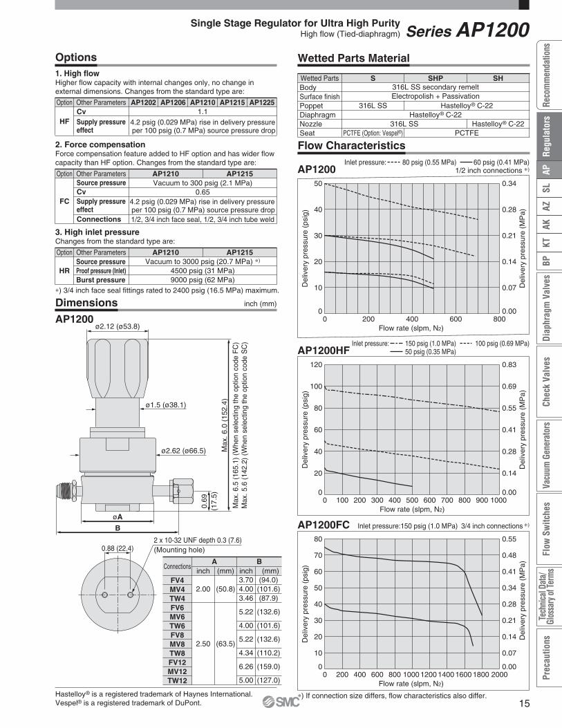
Option Other Parameters
HFCvSupply pressureeffect
AP1202 AP1206 AP1210 AP1215 AP12251.1
4.2 psig (0.029 MPa) rise in delivery pressure per 100 psig (0.7 MPa) source pressure drop
Other Parameters
FC
Source pressureCv
Connections
Supply pressureeffect
Vacuum to 300 psig (2.1 MPa)0.65
1/2, 3/4 inch face seal, 1/2, 3/4 inch tube weld
4.2 psig (0.029 MPa) rise in delivery pressure per 100 psig (0.7 MPa) source pressure drop
Other Parameters
HRSource pressureProof pressure (Inlet)Burst pressure
Vacuum to 3000 psig (20.7 MPa) ∗)
4500 psig (31 MPa)9000 psig (62 MPa)
Option
Option
AP1210 AP1215
AP1210 AP1215
DimensionsAP1200
316L SS secondary remeltElectropolish + Passivation
Hastelloy® C-22316L SS
PCTFE (Option: Vespel®)
Hastelloy® C-22
PCTFE316L SS Hastelloy® C-22
ConnectionsA B
FV4MV4TW4FV6MV6TW6FV8MV8TW8FV12MV12TW12
(50.8)
(63.5)
2.00
2.50
(94.0)(101.6)(87.9)
(132.6)
(101.6)
(132.6)
(110.2)
(159.0)
(127.0)
3.704.003.46
5.22
4.00
5.22
4.34
6.26
5.00
Options1. High flowHigher flow capacity with internal changes only, no change inexternal dimensions. Changes from the standard type are:
2. Force compensationForce compensation feature added to HF option and has wider flow capacity than HF option. Changes from the standard type are:
3. High inlet pressureChanges from the standard type are:
Flow Characteristics
Wetted Parts Material
Wetted PartsBodySurface finishPoppetDiaphragmNozzleSeat
S SH
Hastelloy® is a registered trademark of Haynes International.Vespel® is a registered trademark of DuPont.
SHP
∗) If connection size differs, flow characteristics also differ.
Series AP1200Single Stage Regulator for Ultra High PurityHigh flow (Tied-diaphragm)
inch (mm) inch (mm)
inch (mm)
0
20
40
60
80
100
120
0 100 200 300 400 500 600 700 800 900 1000Flow rate (slpm, N2)
Del
iver
ypr
essu
re(p
sig)
0.00
0.14
0.28
0.41
0.55
0.69
0.83
Del
iver
ypr
essu
re(M
Pa)
0
10
20
30
40
50
60
70
80
0 200 400 600 800 1000 1200 1400 1600 1800 2000Flow rate (slpm, N2)
Del
iver
ypr
essu
re(p
sig)
0.00
0.07
0.14
0.21
0.28
0.34
0.41
0.48
0.55
Del
iver
ypr
essu
re(M
Pa)
0
10
20
30
40
50
0 200 400 600 800Flow rate (slpm, N2)
Del
iver
ypr
essu
re(p
sig)
0.00
0.07
0.14
0.21
0.28
0.34
Del
iver
ypr
essu
re(M
Pa)
AP1200HF150 psig (1.0 MPa)50 psig (0.35 MPa)
Inlet pressure: 100 psig (0.69 MPa)
AP1200FC Inlet pressure:150 psig (1.0 MPa)
AP120080 psig (0.55 MPa)Inlet pressure: 60 psig (0.41 MPa)
1/2 inch connections ∗)
3/4 inch connections ∗)
∗) 3/4 inch face seal fittings rated to 2400 psig (16.5 MPa) maximum.
15
AZAK
KTBP
Diap
hrag
mVa
lves
Chec
kVa
lves
Vacu
umGe
nera
tors
Flow
Switc
hes
Tech
nica
lDat
a/Gl
ossa
ryof
Term
sPr
ecau
tions
SLAP
Reco
mm
enda
tions
Reg
ulat
ors

2.13
(54.
1)
9/16-18 UNF
ø2
(ø50
.7)
1.14 (29)
ø2.
28(ø
57.8
)
3/4 HEX
inch (mm)
inch (mm)
1.94
(49.
3)
ø2
(ø50
.7)
1.14 (29)
ø2.
28(ø
57.8
)
0.73 (18.5)
NPT 1/4
0.73(18.5)
Stainless steel / Lower mount
For AK/BP series (Installed before shipment / Order separately)
Model
-30 in.Hg to 30 psig-30 in.Hg to 60 psig-30 in.Hg to 100 psig-30 in.Hg to 160 psig
0 to 200 psig0 to 400 psig0 to 1000 psig0 to 4000 psig-0.1 to 0.2 MPa-0.1 to 0.4 MPa-0.1 to 0.7 MPa-0.1 to 1.1 MPa
0 to 1.4 MPa0 to 3 MPa0 to 7 MPa0 to 28 MPa
psig/bar ∗4)
MPa
00-8300002300-8300002600-8300002100-8300011600-8300002000-8300000700-8300002200-8300002400-8300030400-8300030500-8300030000-8300029700-8300029900-8300030100-8300030200-83000303
(No code)
MPA
V3L1H241040V3L1H241040
unitgauge portPressurerange Unit
Regulator Code ∗2)Part number ∗3)
Model
-30 in.Hg to 15 psig-30 in.Hg to 30 psig-30 in.Hg to 60 psig-30 in.Hg to 100 psig-30 in.Hg to 160 psig-30 in.Hg to 200 psig
0 to 200 psig0 to 400 psig0 to 1000 psig0 to 3000 psig0 to 4000 psig-0.1 to 0.1 MPa-0.1 to 0.2 MPa-0.1 to 0.4 MPa-0.1 to 0.7 MPa-0.1 to 1.1 MPa-0.1 to 1.4 MPa
0 to 1.5 MPa0 to 3 MPa0 to 7 MPa0 to 21 MPa0 to 28 MPa
psig/bar ∗4)
MPa
00-8300010200-8300018400-8300018100-8300018200-8300019600-8300003300-8300019300-8300019400-8300018700-8300023400-8300018300-8300028700-8300028800-8300028900-8300029000-8300029100-8300029200-8300028600-8300028500-8300028400-8300028300-83000282
(No code)
MPA
V15V3L1HV224103040
V15V3L1HV224103040
unitgauge portPressure range Unit
Regulator Code ∗2)Part number ∗3)
SSH
material
SpecificationsInstallation
Gas
ConnectionsTemperature range
Accuracy
CleanlinessNo oil
Material
Lower mount
NPT 1/4 inch–40 to 140°F (–40 to 60°C) (No freezing)
ASME B40.1 level IVNo oil
Stainless steelPolycarbonate
316L SS316L SS
25% to 75% of the scale: ±2%F.S.Other than above: ±3%F.S.
(ASME B40.1 Grade B or better)
CaseWindowSocketBourdon tube
For AP/SL/AZ series (Installed before shipment ∗1) / Order separately)SpecificationsInstallation
Gas
ConnectionsTemperature range
Accuracy
CleanlinessNo oil
Material
Lower mount
1/4 inch face seal (Female)–40 to 140°F (–40 to 60°C) (No freezing)
ASME B40.1 level IVNo oil
Stainless steelPolycarbonate
316L SS316L SS
CaseWindowSocketBourdon tube
25% to 75% of the scale: ±1%F.S.Other than above: ±2%F.S.
(ASME B40.1 Grade A)
Select compatible materialsof construction for the gas
Select compatible materialsof construction for the gas
Regulator
Pressure Gauges Guide
∗1) If one prefers shipment with the pressure gauges installed on the regulator, the material of gasket to be used on the connections will be Nickel(no plated). Please contact SMC for details if one prefers changing this material.
∗2) When pressure gauge needs to be assembled with regulator when shipment, put this code as gauge port in How to Order.
94
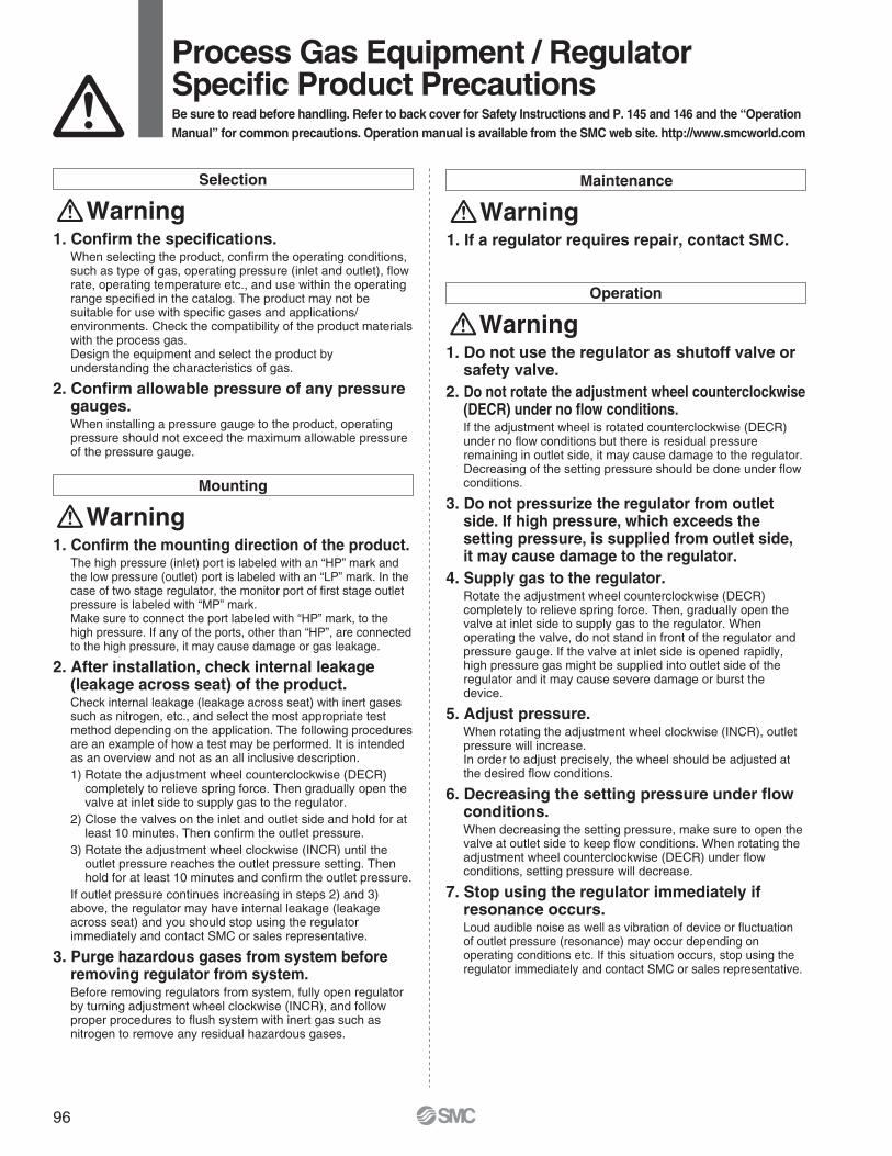
1. Do not use the regulator as shutoff valve orsafety valve.
2. Do not rotate the adjustment wheel counterclockwise (DECR) under no flow conditions.If the adjustment wheel is rotated counterclockwise (DECR) under no flow conditions but there is residual pressure remaining in outlet side, it may cause damage to the regulator.Decreasing of the setting pressure should be done under flowconditions.
3. Do not pressurize the regulator from outlet side. If high pressure, which exceeds the setting pressure, is supplied from outlet side, it may cause damage to the regulator.
4. Supply gas to the regulator.Rotate the adjustment wheel counterclockwise (DECR) completely to relieve spring force. Then, gradually open the valve at inlet side to supply gas to the regulator. Whenoperating the valve, do not stand in front of the regulator and pressure gauge. If the valve at inlet side is opened rapidly, high pressure gas might be supplied into outlet side of the regulator and it may cause severe damage or burst the device.
5. Adjust pressure.When rotating the adjustment wheel clockwise (INCR), outletpressure will increase.In order to adjust precisely, the wheel should be adjusted at the desired flow conditions.
6. Decreasing the setting pressure under flow conditions.When decreasing the setting pressure, make sure to open the valve at outlet side to keep flow conditions. When rotating theadjustment wheel counterclockwise (DECR) under flowconditions, setting pressure will decrease.
7. Stop using the regulator immediately if resonance occurs.Loud audible noise as well as vibration of device or fluctuation of outlet pressure (resonance) may occur depending on operating conditions etc. If this situation occurs, stop using theregulator immediately and contact SMC or sales representative.
Operation
Warning
Selection
Warning1. Confirm the specifications.
When selecting the product, confirm the operating conditions, such as type of gas, operating pressure (inlet and outlet), flowrate, operating temperature etc., and use within the operating range specified in the catalog. The product may not besuitable for use with specific gases and applications/environments. Check the compatibility of the product materialswith the process gas.Design the equipment and select the product byunderstanding the characteristics of gas.
2. Confirm allowable pressure of any pressuregauges.When installing a pressure gauge to the product, operating pressure should not exceed the maximum allowable pressureof the pressure gauge.
Mounting
Warning1. Confirm the mounting direction of the product.
The high pressure (inlet) port is labeled with an “HP” mark andthe low pressure (outlet) port is labeled with an “LP” mark. In thecase of two stage regulator, the monitor port of first stage outlet pressure is labeled with “MP” mark.Make sure to connect the port labeled with “HP” mark, to thehigh pressure. If any of the ports, other than “HP”, are connected to the high pressure, it may cause damage or gas leakage.
2. After installation, check internal leakage(leakage across seat) of the product.Check internal leakage (leakage across seat) with inert gasessuch as nitrogen, etc., and select the most appropriate testmethod depending on the application. The following proceduresare an example of how a test may be performed. It is intended as an overview and not as an all inclusive description.1) Rotate the adjustment wheel counterclockwise (DECR)
completely to relieve spring force. Then gradually open thevalve at inlet side to supply gas to the regulator.
2) Close the valves on the inlet and outlet side and hold for atleast 10 minutes. Then confirm the outlet pressure.
3) Rotate the adjustment wheel clockwise (INCR) until theoutlet pressure reaches the outlet pressure setting. Thenhold for at least 10 minutes and confirm the outlet pressure.
If outlet pressure continues increasing in steps 2) and 3)above, the regulator may have internal leakage (leakageacross seat) and you should stop using the regulatorimmediately and contact SMC or sales representative.
3. Purge hazardous gases from system beforeremoving regulator from system.Before removing regulators from system, fully open regulatorby turning adjustment wheel clockwise (INCR), and followproper procedures to flush system with inert gas such asnitrogen to remove any residual hazardous gases.
Maintenance
Warning1. If a regulator requires repair, contact SMC.
Process Gas Equipment / RegulatorSpecific Product PrecautionsBe sure to read before handling. Refer to back cover for Safety Instructions and P. 145 and 146 and the “Operation Manual” for common precautions. Operation manual is available from the SMC web site. http://www.smcworld.com
96

Operation
Warning1. Do not use the back pressure regulator as
shutoff valve or safety valve.2. Pressure control
1) Rotate the adjustment wheel counterclockwise completely to relieve spring force.
2) Partially open the valve at inlet side to supply gas to theback pressure regulator.
3) Increase the inlet pressure to the setting pressure by rotating the adjustment wheel clockwise.
4) Continue opening the valve at inlet side monitoring the inlet pressure. When the inlet pressure increases above thesetting pressure, rotate the adjustment wheel counterclockwise to relieve the inlet pressure to the setting pressure.
5) Open the valve at inlet side completely and confirm that the inlet pressure reaches the setting pressure.
3. Decreasing the setting pressure.When decreasing the setting pressure, make sure to gradually rotate the adjustment wheel counterclockwise until the inlet pressure reaches the setting pressure.
4. Stop using the regulator immediately if resonance occurs.Loud audible noise as well as vibration of device or fluctuationof outlet pressure (resonance) may occur depending on operating conditions, etc. If this situation occurs, stop usingthe regulator immediately and contact SMC or sales representative.
Selection
Warning1. Confirm the specifications.
When selecting the product, confirm the operating conditions, such as type of gas, operating pressure (inlet and outlet), flow rate, operating temperature etc., and use within the operating range specified in the catalog. Verify flow capacity of regulator and vent or return line, are large enough to vent off gas source without creating excessive backpressure. The product may not be suitable for use with specific gases andapplications/environments. Check the compatibility of the product materials with the process gas.Design the equipment and select the product by understanding the characteristics of gas.
2. Confirm allowable pressure of any pressuregauges.When installing pressure gauges to the product, operating pressure should not exceed the maximum allowable pressure of the pressure gauge.
Mounting
Warning1. Confirm the mounting direction of the product.
The high pressure (inlet) port is labeled with an “IN” mark and the low pressure (outlet) port is labeled with an “OUT” mark.Make sure to connect the port labeled with “IN” mark, to the high pressure. If any of the ports, other than “IN”, is connected to the high pressure, it may cause damage or gas leakage.
Maintenance
Warning1. If a back pressure regulator requires repair,
contact SMC.
Process Gas Equipment / Back Pressure RegulatorSpecific Product PrecautionsBe sure to read before handling. Refer to back cover for Safety Instructions and P. 145 and 146 and the “Operation Manual” for common precautions. Operation manual is available from the SMC web site. http://www.smcworld.com
97
AZAK
KTBP
Diap
hrag
mVa
lves
Chec
kVa
lves
Vacu
umGe
nera
tors
Flow
Switc
hes
Tech
nica
lDat
a/Gl
ossa
ryof
Term
sPr
ecau
tions
SLAP
Reco
mm
enda
tions
Reg
ulat
ors

Operating Parameters
Delivery pressure
GasSource pressureProof pressure (Inlet)Burst pressureAmbient and operating temperatureCv
Leak rate
Across the seat leakSurface finishConnectionsBonnet portSupply pressure effectInstallationInternal volumeMass
AP15021 to 30 psig
(0.007 to 0.2 MPa)
AP15062 to 60 psig
(0.014 to 0.4 MPa)
Vacuum to 3500 psig (24.1 MPa)
AP15102 to 100 psig
(0.014 to 0.7 MPa)
AP15155 to 150 psig
(0.034 to 1.0 MPa)Select compatible materials of construction for the gas
5000 psig (34.5 MPa)10000 psig (69MPa)
–40 to 160°F (–40 to 71 °C) (No freezing) ∗1)
0.092 x 10⁻¹¹ Pa·m3/sec
2 x 10⁻¹⁰ Pa·m3/sec ∗2)
4 x 10⁻⁹ Pa·m3/sec ∗3)
Ra max 15 µin. (0.4 µm) Option: 10 µin. (0.25 µm), 7 µin. (0.18 µm), 5 µin. (0.13 µm)Face seal, Tube weld
NPT 1/8 inch ∗4)
0.41 psig (0.0028 MPa) rise in delivery pressure per 100 psig (0.7 MPa) source pressure dropBottom mount (Option: panel mount)
0.51 in3 (8.4 cm3)2.8lbs (1.27 kg) ∗5)
∗1) 14 to 194°F (-10 to 90 °C) for Vespel® seat.∗2) Tested with Helium gas inlet pressure 1500 psig (10.5 MPa).∗3) Tested with Helium gas inlet pressure 1000 psig (7 MPa).
∗4) On panel mount option, bonnet port is not threaded.∗5) Mass, including individual boxed weight, may vary depending on connections or options.
Specifications
Porting Configuration
3PW
w q
r
2PW
w q
4PW
w q
r e
Inboard leakageOutboard leakage
¡For UHP gas delivery¡High inlet pressure type: Max. 3500 psig (24.1 MPa)¡Flow capacity : to 30 slpm¡Body material: 316L SS secondary remelt¡Hastelloy internals available for corrosion resistance¡Tied-diaphragm design
Low flow(Tied-diaphragm)
Series AP1500
Single Stage Regulator for Ultra High Purity
Bonnet option
No codeP
BonnetStandard
Panel installation ∗4)
Code
∗4) Panel mounting hole:dia. 1.56 inch (39.6 mm).
AP15 S FV4 FV402 2PW
Surface finish
No codeMVX
Surface finish Ra max15 µin. (0.4 µm) Standard
10 µin. (0.25 µm)7 µin. (0.18 µm)5 µin. (0.13 µm)
CodePorts
2PW3PW4PW
Ports2 port3 port4 port
Code
Connections (Inletq, Outletw)
FV4MV4TW4FV6MV6TW6
Connections1/4 inch face seal (Female)
1/4 inch face seal (Male)1/4 inch tube weld
3/8 inch face seal (Female)3/8 inch face seal (Male)
3/8 inch tube weld
Code
Seat material
No code
VS
MaterialPCTFE
(Standard)Vespel® ∗3)
Code
∗3) Not available with SHP,SH, H materials.
Port Numberq w e r
Delivery pressure
02061015
Delivery pressure1 to 30 psig (0.007 to 0.2 MPa)2 to 60 psig (0.014 to 0.4 MPa)2 to 100 psig (0.014 to 0.7 MPa)5 to 150 psig (0.034 to 1.0 MPa)
Code
Material
Hastelloy®
C-22
Nozzle
316L SS
Diaphragm316L SS
Hastelloy®
C-22
Poppet316L SS
Hastelloy®
C-22
316L SSsecondary
remelt
Body
Hastelloy®
C-22
SSHPSH
H
Code
Pressure gauge unit ∗2)
No codeMPA
Unitpsig/bar
MPa
Code
∗2) Pressure gauge unit MPa orpsig/bar selectable. Howeverunder Japanese regulation, onlyMPa is available in Japan.
qIN wOUT eGauge port (Inlet) rGauge port (Outlet)
Gauge port (Inlete, Outletr)
No code
0
V3L1H241040
No gauge port
-30 in.Hg to 30 psig-30 in.Hg to 60 psig-30 in.Hg to 100 psig-30 in.Hg to 160 psig
0 to 200 psig0 to 400 psig0 to 1000 psig0 to 4000 psig
-0.1 to 0.2 MPa-0.1 to 0.4 MPa-0.1 to 0.7 MPa-0.1 to 1.1 MPa0 to 1.4 MPa0 to 3 MPa0 to 7 MPa0 to 28 MPa
Pressure gauge ∗1)
psig/bar unit MPa unit
No pressure gauge(Connections: 1/4 inch face seal male)
Code
∗1) Refer to gauge guide (P.94) for gauge specifications.
2PW3PW3PW4PW
AP1510Se
40
w
FV4FV4FV4FV4
q
FV4FV4FV4FV4
r
011
MPAMPA
Sample Order NumberPort
How to Order
6

ø1.5 (ø38.1)
ø2.25 (ø57.2)
INOUT
ø2.00 (ø50.8)
0.69
(17.
5)M
ax.5
.6(1
42.2
)
A
2 x 10-32 UNF depth 0.3 (7.6)(Mounting hole)
0.88 (22.4)
ø2.12 (ø53.8)
Wetted PartsBodySurface finishPoppetDiaphragmNozzleSeat
S316L SS secondary remeltElectropolish + Passivation
SHP
316L SS
SH HHastelloy® C-22
ElectropolishHastelloy® C-22Hastelloy® C-22
Hastelloy® C-22PCTFE
316L SS316L SS
PCTFE (Option: Vespel®)
Wetted Parts Material
Hastelloy® is a registered trademark of Haynes International.Vespel® is a registered trademark of DuPont.
Flow Characteristics
Dimensions
AP1500
inch (mm)A
FV4MV4TW4FV6MV6TW6
3.70
2.96
4.70
2.96
(94.0)
(75.2)
(119.4)
(75.2)
Series AP1500Single Stage Regulator for Ultra High PurityLow flow (Tied-diaphragm)
inch (mm)
010
20
30
40
50
60
70
80
90
100
0 100 200 300 400Flow rate (slpm, N2)
Del
iver
ypr
essu
re(p
sig)
0.000.07
0.14
0.21
0.28
0.34
0.41
0.48
0.55
0.62
0.69
Del
iver
ypr
essu
re(M
Pa)
AP1500
0
10
20
30
40
50
0 20 40 60 80Flow rate (slpm, N2)
Del
iver
ypr
essu
re(p
sig)
0.00
0.07
0.14
0.21
0.28
0.34D
eliv
ery
pres
sure
(MP
a)
2000 to 3000 psig (13.8 to 20.7 MPa)500 psig (3.4 MPa)
Inlet pressure: 1000 psig (6.9 MPa)200 psig (1.4 MPa) AP1500
100 psig (0.69 MPa)40 psig (0.28 MPa)
Inlet pressure: 80 psig (0.55 MPa)20 psig (0.14 MPa)
7
AZAK
KTBP
Diap
hrag
mVa
lves
Chec
kVa
lves
Vacu
umGe
nera
tors
Flow
Switc
hes
Tech
nica
lDat
a/Gl
ossa
ryof
Term
sPr
ecau
tions
SLAP
Reco
mm
enda
tions
Reg
ulat
ors

Operating Parameters
Delivery pressure
Gas
Source pressure
Proof pressure (Inlet)Burst pressureAmbient and operating temperatureCv
Leak rate
Across the seat leakSurface finishConnectionsBonnet portSupply pressure effectInstallationInternal volumeMass
AP16011 to 10 psig
(0.007 to 0.07 MPa)
Vacuum to 100 psig(0.7 MPa)
AP16021 to 30 psig
(0.007 to 0.2 MPa)
AP16062 to 60 psig
(0.014 to 0.4 MPa)
AP16102 to 100 psig
(0.014 to 0.7 MPa)Select compatible materials of construction for the gas
4000 psig (27.6 MPa)8000 psig (55.2 MPa)
–40 to 160°F (–40 to 71 °C) (No freezing) ∗1)
0.132 x 10⁻¹¹ Pa·m3/sec
2 x 10⁻¹⁰ Pa·m3/sec ∗2)
4 x 10⁻⁹ Pa·m3/sec ∗3)
Ra max 15 µin. (0.4 µm) Option: 10 µin. (0.25 µm), 7 µin. (0.18 µm), 5 µin. (0.13 µm)Face seal, Tube weld
NPT 1/8 inch ∗4)
0.25 psig (0.0017 MPa) rise in delivery pressure per 100 psig (0.7 MPa) source pressure dropBottom mount (Option: panel mount)
0.82 in3 (13.5 cm3)3.39 lbs (1.54 kg) ∗5)
∗1) 14 to 194°F (-10 to 90°C) for Vespel® seat.∗2) Tested with Helium gas inlet pressure 1500 psig (10.5 MPa).∗3) Tested with Helium gas inlet pressure 500 psig (3.5 MPa).
∗4) On panel mount option, bonnet port is not threaded.∗5) Mass, including individual boxed weight, may vary depending on connections or options.
Specifications
Porting Configuration
3PW
w q
r
2PW
w q
4PW
w q
r e
Vacuum to 3500 psig (24.1 MPa)
Inboard leakageOutboard leakage
¡For UHP gas delivery¡High inlet pressure type: Max. 3500 psig (24.1 MPa)¡Flow capacity: to 100 slpm¡Body material: 316L SS secondary remelt¡Hastelloy internals available for corrosion resistance
Series AP1600
Single Stage Regulator for Ultra High Purity
Bonnet option
No codeP
BonnetStandard
Panel installation ∗4)
Code
∗4) Panel mounting hole:dia. 1.43 inch (36.3 mm).
AP16 S FV4 FV401 2PW
Surface finish
No codeMVX
Surface finish Ra max15 µin. (0.4 µm) Standard
10 µin. (0.25 µm)7 µin. (0.18 µm)5 µin. (0.13 µm)
CodePorts
2PW3PW4PW
Ports2 ports3 ports4 ports
Code
Connections (Inletq, Outletw)
FV4MV4TW4FV6MV6TW6
Connections1/4 inch face seal (Female)
1/4 inch face seal (Male)1/4 inch tube weld
3/8 inch face seal (Female)3/8 inch face seal (Male)
3/8 inch tube weld
Code
Seat material
No code
VS
MaterialPCTFE
(Standard)Vespel® ∗3)
Code
∗3) Not available with SH material.
Port Numberq w e r
Delivery pressure
01020610
Delivery pressure1 to 10 psig (0.007 to 0.07 MPa)1 to 30 psig (0.007 to 0.2 MPa)2 to 60 psig (0.014 to 0.4 MPa)2 to 100 psig (0.014 to 0.7 MPa)
Code
No code
0
V3L11040
Pressure gauge ∗1)
No gauge port
-30 in.Hg to 30 psig-30 in.Hg to 60 psig-30 in.Hg to 100 psig
0 to 1000 psig0 to 4000 psig
-0.1 to 0.2 MPa-0.1 to 0.4 MPa-0.1 to 0.7 MPa
0 to 7 MPa0 to 28 MPa
No pressure gauge(Connections: 1/4 inch face seal male)
Code
316L SSsecondary
remelt
Material
S
SH
Body Poppet316L SS
Diaphragm316L SS
Nozzle316L SS
Hastelloy®
C-22Hastelloy®
C-22Hastelloy®
C-22
Code
Pressure gauge unit ∗2)
No codeMPA
Unitpsig/bar
MPa
Code
Gauge port (Inlete, Outletr)
Low to intermediate flow
∗2) Pressure gauge unit MPa orpsig/bar selectable. Howeverunder Japanese regulation, only MPa is available in Japan.∗1) Refer to gauge guide (P.94) for gauge
specifications.
qIN wOUT eGauge port (Inlet) rGauge port (Outlet)
2PW3PW3PW4PW
AP1601Se
1
w
FV4FV4FV4FV4
q
FV4FV4FV4FV4
r
0V3V3 MPA
Sample Order NumberPort
psig/bar unit MPa unit
How to Order
8

ø1.5 (ø38.1)
ø2.62 (ø66.5)
0.69
(17.
5)
ø2.5 (ø63.5)
A
Max
.5.5
(139
.7)
2 x 10-32 UNF depth 0.3 (7.6)(Mounting hole)
0.88 (22.4)
INOUT
ø2.12 (ø53.8)
Wetted Parts Material
Hastelloy® is a registered trademark of Haynes International.Vespel® is a registered trademark of DuPont.
Flow Characteristics
Dimensions
AP1600
Connectionsinch (mm)
A
FV4MV4TW4FV6MV6TW6
4.30
3.46
5.22
4.00
(109.2)
(87.9)
(132.6)
(101.6)
Wetted PartsBodySurface finishPoppetDiaphragmNozzleSeat
S316L SS secondary remeltElectropolish + Passivation
316L SS316L SS316L SS
PCTFE (Option: Vespel®)
Hastelloy® C-22Hastelloy® C-22Hastelloy® C-22
PCTFE
SH
Series AP1600Single Stage Regulator for Ultra High PurityLow to intermediate flow
inch (mm)
010
20
30
40
50
60
70
80
90
100
0 100 200 300 400 500 600Flow rate (slpm, N2)
Del
iver
ypr
essu
re(p
sig)
0.000.07
0.14
0.21
0.28
0.34
0.41
0.48
0.55
0.62
0.69
Del
iver
ypr
essu
re(M
Pa)
0
10
20
30
40
50
60
0 50 100 150Flow rate (slpm, N2)
Del
iver
ypr
essu
re(p
sig)
0.00
0.07
0.14
0.21
0.28
0.34
0.41D
eliv
ery
pres
sure
(MP
a)
AP16002000 to 3000 psig (13.8 to 20.7 MPa)500 psig (3.4 MPa)
Inlet pressure: 1000 psig (0.69 MPa)200 psig (1.4 MPa) AP1600
100 psig (0.69 MPa)60 psig (0.41 MPa)
Inlet pressure: 80 psig (0.55 MPa)
9
AZAK
KTBP
Diap
hrag
mVa
lves
Chec
kVa
lves
Vacu
umGe
nera
tors
Flow
Switc
hes
Tech
nica
lDat
a/Gl
ossa
ryof
Term
sPr
ecau
tions
SLAP
Reco
mm
enda
tions
Reg
ulat
ors

Operating Parameters
Delivery pressure
GasSource pressureProof pressure (Inlet)Burst pressureAmbient and operating temperatureCv
Leak rate
Across the seat leakSurface finishConnectionsBonnet portSupply pressure effectInstallationInternal volumeMass
AP19011 to 10 psig
(0.007 to 0.07 MPa)
AP19021 to 30 psig
(0.007 to 0.2 MPa)
AP19062 to 60 psig
(0.014 to 0.4 MPa)
AP19102 to 100 psig
(0.014 to 0.7 MPa)Select compatible materials of construction for the gas
Vacuum to 3500 psig (24.1 MPa)4000 psig (27.6 MPa)8000 psig (55.2 MPa)
–40 to 160°F (–40 to 71 °C) (No freezing) ∗1)
0.132 x 10⁻¹¹ Pa·m3/sec
2 x 10⁻¹⁰ Pa·m3/sec ∗2)
4 x 10⁻⁹ Pa·m3/sec ∗3)
Ra max 15 µin. (0.4 µm) Option: 10 µin. (0.25 µm), 7 µin. (0.18 µm), 5 µin. (0.13 µm)Face seal, Tube weld
NPT 1/8 inch ∗4)
0.25 psig (0.0017 MPa) rise in delivery pressure per 100 psig (0.7 MPa) source pressure dropBottom mount (Option: panel mount)
0.82 in3 (13.5 cm3)3.39lbs (1.54 kg) ∗5)
AP19155 to 150 psig
(0.034 to 1.0 MPa)
∗1) 14 to 194°F (–10 to 90 °C) for Vespel® seat.∗2) Tested with Helium gas inlet pressure 1500 psig (10.5 MPa).∗3) Tested with Helium gas inlet pressure 1000 psig (7 MPa).
∗4) On panel mount option, bonnet port is not threaded.∗5) Mass, including individual boxed weight, may vary depending on connections or options.
Specifications
Porting Configuration
3PW
w q
r
2PW
w q
4PW
w q
r e
Inboard leakageOutboard leakage
¡For UHP gas delivery¡High inlet pressure type: Max. 3500 psig (24.1 MPa)¡Body material: 316L SS secondary remelt¡Hastelloy internals available for corrosion resistance¡Tied-diaphragm design
Low to intermediate flow(Tied-diaphragm)
Series AP1900
Single Stage Regulator for Ultra High Purity
Bonnet option
No codeP
BonnetStandard
Panel installation ∗4)
Code
∗4) Panel mounting hole: dia.1.43 inch (36.3 mm).
AP19 S FV4 FV401 2PW
Surface finish
No codeMVX
Surface finish Ra max15 µin. (0.4 µm) Standard
10 µin. (0.25 µm)7 µin. (0.18 µm)5 µin. (0.13 µm)
CodePorts
2PW3PW4PW
Ports2 ports3 ports4 ports
Code
Connections (Inletq, Outletw)
FV4MV4TW4FV6MV6TW6FV8MV8TW8
Connections1/4 inch face seal (Female)
1/4 inch face seal (Male)1/4 inch tube weld
3/8 inch face seal (Female)3/8 inch face seal (Male)
3/8 inch tube weld1/2 inch face seal (Female)
1/2 inch face seal (Male)1/2 inch tube weld
Code
Seat material
No codeVS
MaterialPCTFE (Standard)
Vespel® ∗3)
Code
∗3) Not available with SH material.
Port Numberq w e r
Delivery pressure
0102061015
Delivery pressure1 to 10 psig (0.007 to 0.07 MPa)1 to 30 psig (0.007 to 0.2 MPa)2 to 60 psig (0.014 to 0.4 MPa)2 to 100 psig (0.014 to 0.7 MPa)5 to 150 psig (0.034 to 1.0 MPa)
Code
Gauge port (Inlete, Outletr)
No code
0
V3L11040
Pressure gauge ∗1)
No gauge port
-30 in.Hg to 30 psig-30 in.Hg to 60 psig-30 in.Hg to 100 psig
0 to 1000 psig0 to 4000 psig
-0.1 to 0.2 MPa-0.1 to 0.4 MPa-0.1 to 0.7 MPa
0 to 7 MPa0 to 28 MPa
No pressure gauge(Connections: 1/4 inch face seal male)
Code
316L SSsecondary
remelt
Material
S
SH
Body Poppet316L SS
Diaphragm316L SS
Nozzle316L SS
Hastelloy®
C-22Hastelloy®
C-22Hastelloy®
C-22
Code Option
No codeHF
SpecificationStandard (Cv: 0.13)High flow (Cv: 0.16)
Code
Pressure gauge unit ∗2)
No codeMPA
Unitpsig/bar
MPa
Code
∗2) Pressure gauge unit MPa orpsig/bar selectable. Howeverunder Japanese regulation, only MPa is available in Japan.
∗1) Refer to gauge guide (P.94) for gauge specifications.
qIN wOUT eGauge port (Inlet) rGauge port (Outlet)qIN wOUT eGauge port (Inlet) rGauge port (Outlet)
2PW3PW3PW4PW
AP1901Se
40
w
FV4FV4FV4FV4
q
FV4FV4FV4FV4
r
0V3V3
MPAMPA
Sample Order NumberPort
psig/bar unit MPa unit
How to Order
10
ø1.5 (ø38.1)
ø2.62 (ø66.5)
ø2.5 (ø63.5)
0.69
(17.
5)
A
Max
.5.5
(139
.7)
2 x 10-32 UNF depth 0.3 (7.6)(Mounting hole)
0.88 (22.4)
INOUT
ø2.12 (ø53.8)
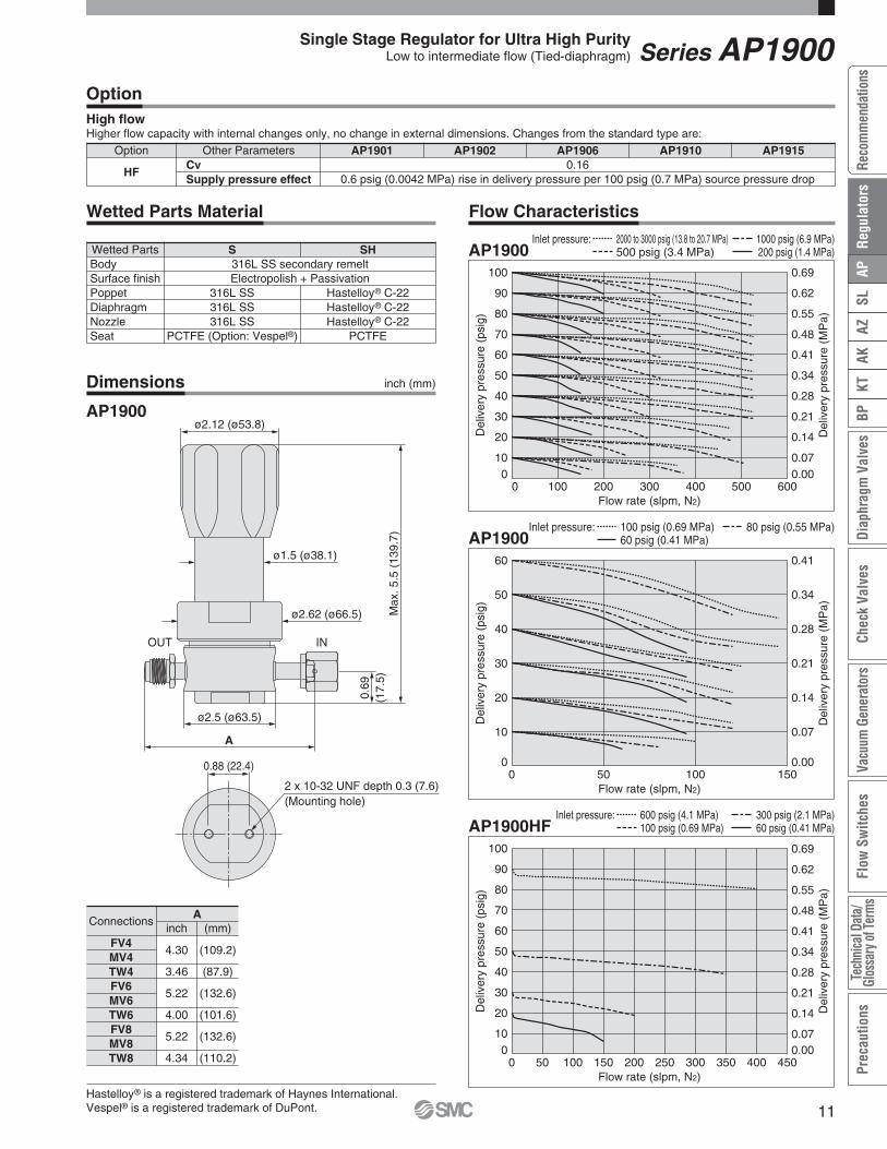
Option Other Parameters
HFCvSupply pressure effect
AP1901 AP1902 AP1906 AP19100.16
0.6 psig (0.0042 MPa) rise in delivery pressure per 100 psig (0.7 MPa) source pressure drop
AP1915
OptionHigh flowHigher flow capacity with internal changes only, no change in external dimensions. Changes from the standard type are:
Connectionsinch (mm)
A
FV4MV4TW4FV6MV6TW6FV8MV8TW8
4.30
3.46
5.22
4.00
5.22
4.34
(109.2)
(87.9)
(132.6)
(101.6)
(132.6)
(110.2)
Wetted PartsBodySurface finishPoppetDiaphragmNozzleSeat
S316L SS secondary remeltElectropolish + Passivation
SH
Hastelloy® C-22Hastelloy® C-22Hastelloy® C-22
PCTFE
Wetted Parts Material
316L SS316L SS316L SS
PCTFE (Option: Vespel®)
Hastelloy® is a registered trademark of Haynes International.Vespel® is a registered trademark of DuPont.
Dimensions
AP1900
Flow Characteristics
Series AP1900Single Stage Regulator for Ultra High PurityLow to intermediate flow (Tied-diaphragm)
inch (mm)
010
20
30
40
50
60
70
80
90
100
0 100 200 300 400 500 600Flow rate (slpm, N2)
Del
iver
ypr
essu
re(p
sig)
0.000.07
0.14
0.21
0.28
0.34
0.41
0.48
0.55
0.62
0.69
Del
iver
ypr
essu
re(M
Pa)
010
20
30
40
50
60
70
80
90
100
0 50 100 150 200 250 300 350 400 450Flow rate (slpm, N2)
Del
iver
ypr
essu
re(p
sig)
0.000.07
0.14
0.21
0.28
0.34
0.41
0.48
0.55
0.62
0.69
Del
iver
ypr
essu
re(M
Pa)
0
10
20
30
40
50
60
0 50 100 150Flow rate (slpm, N2)
Del
iver
ypr
essu
re(p
sig)
0.00
0.07
0.14
0.21
0.28
0.34
0.41
Del
iver
ypr
essu
re(M
Pa)
AP19002000 to 3000 psig (13.8 to 20.7 MPa)500 psig (3.4 MPa)
Inlet pressure: 1000 psig (6.9 MPa)200 psig (1.4 MPa)
AP1900100 psig (0.69 MPa)60 psig (0.41 MPa)
Inlet pressure: 80 psig (0.55 MPa)
AP1900HF600 psig (4.1 MPa)100 psig (0.69 MPa)
Inlet pressure: 300 psig (2.1 MPa)60 psig (0.41 MPa)
11
AZAK
KTBP
Diap
hrag
mVa
lves
Chec
kVa
lves
Vacu
umGe
nera
tors
Flow
Switc
hes
Tech
nica
lDat
a/Gl
ossa
ryof
Term
sPr
ecau
tions
SLAP
Reco
mm
enda
tions
Reg
ulat
ors

Porting Configuration
3PW
w q
r
2PW
w q
4PW
w q
r e
Operating Parameters
Delivery pressure
GasSource pressureProof pressure (Inlet)Burst pressureAmbient and operating temperatureCv
Leak rate
Across the seat leakSurface finishConnectionsBonnet portSupply pressure effectInstallationInternal volumeMass
AP1402TmmA100 mm Hg absolute to 30 psig
(-88kPa to 0.2MPa)
Vacuum to 300 psig (2.1 MPa)
AP1402T1 to 30 psig
(0.007 to 0.2 MPa)
AP1406T2 to 60 psig
(0.014 to 0.4 MPa)
AP1410T2 to 100 psig
(0.014 to 0.7 MPa)Select compatible materials of construction for the gas
4000 psig (27.6 MPa)8000 psig (55.2 MPa)
–40 to 160°F (–40 to 71°C) (No freezing) ∗2)
0.452 x 10⁻¹¹ Pa·m3/sec
2 x 10⁻¹⁰ Pa·m3/sec ∗3)
4 x 10⁻⁹ Pa·m3/sec ∗4)
Ra max 15 µin. (0.4 µm) Option: 10 µin. (0.25 µm), 7 µin. (0.18 µm), 5 µin. (0.13 µm)Face seal, Tube weld
NPT 1/8 inch ∗5)
1.6 psig(0.011 MPa) rise in delivery pressure per 100 psig (0.7 MPa) source pressure dropBottom mount (Option: panel mount)
1.06 in3 (17.4 cm3)4.5 lbs (2.04 kg) ∗6)
Vacuum to 2300 psig(15.9 MPa)
AP1415T5 to 150 psig (0.034 to 1.0 MPa)
(Source pressure 1000 psig or less) ∗1)
∗2) 14 to 194°F (–10 to 90°C) for Vespel® seat.∗3) Tested with Helium gas inlet pressure 1500 psig (10.5 MPa).∗4) Tested with Helium gas inlet pressure 1000 psig (7 MPa).∗5) On panel mount option, bonnet port is not threaded.∗6) Mass, including individual boxed weight, may vary depending on connections or options.
Specifications
Inboard leakageOutboard leakage
∗1) Source pressure above 1000 psig (6.9 MPa) decreases maximumdelivery pressure to less than 150 psig (1 MPa) due to supplypressure effect. When the source pressure is 2300 psig (15.9MPa), achievable delivery pressure is around 129 psig (0.89MPa).
¡For UHP gas delivery¡High inlet pressure type Standard: Max. 2300 psig(15.9 MPa)
HR(option): Max. 3000 psig (20.7 MPa)¡Flow capacity : to 400 slpm¡Body material: 316L SS secondary remelt¡Hastelloy internals standard
Intermediate flow(Tied-diaphragm)
Series AP1400T
Single Stage Regulator for Ultra High Purity
AP14 S FV4 FV402 2PW
Surface finish
No codeMVX
Surface finish Ra max15 µin. (0.4 µm) Standard
10 µin. (0.25 µm)7 µin. (0.18 µm)5 µin. (0.13 µm)
Code
Ports
2PW3PW4PW
Ports2 ports3 ports4 ports
Code
Connections (Inletq, Outletw)
FV4MV4TW4FV6MV6TW6FV8MV8TW8
Connections1/4 inch face seal (Female)
1/4 inch face seal (Male)1/4 inch tube weld
3/8 inch face seal (Female)3/8 inch face seal (Male)
3/8 inch tube weld1/2 inch face seal (Female)
1/2 inch face seal (Male)1/2 inch tube weld
Code
Seat material
No codeVS
MaterialPCTFE (Standard)
Vespel® ∗4)
Code
∗4) Not available with SH material.
Port Numberq w e r
Gauge port (Inlete, Outletr)
No code
0
V3L1H241040
Pressure gauge ∗2)
No gauge portNo pressure gauge
(Connections: 1/4 inch face seal male)
Code
∗2) Refer to gauge guide (P.94) for gauge specifications.
Delivery pressure
02
061015
Delivery pressure
2 to 60 psig (0.014 to 0.4 MPa)2 to 100 psig (0.014 to 0.7 MPa)5 to 150 psig (0.034 to 1.0 MPa)
Code1 to 30 psig (0.007 to 0.2 MPa)
Sub-atmospheric(A):100 mm Hg absolute to 30 psig (-88 kPa to 0.2 MPa)
T
Range options ∗1)
No codeA
RangeStandard
Sub-atmospheric
Code
∗1) Only available with AP1402T.
Bonnet option
∗6) Panel mounting hole: 1.56 inch (39.6 mm).
∗7) Bonnet port is not threaded.SC option not available with 1402TA option.
316L SSsecondary
remelt
Material
S
SH
Body Poppet Diaphragm Nozzle316L SS
Hastelloy®
C-22
Hastelloy®
C-22Hastelloy®
C-22
Code
Option
∗5) Not available withAP1402T and AP1406T.
Pressure gauge unit ∗3)
No codeMPA
Unitpsig/bar
MPa
Code
∗3) Pressure gauge unit MPa or psig/barselectable. However under Japaneseregulation, only MPa is available in Japan.
No codeP
SC
BonnetStandard
Panel installation ∗6)
Short type ∗7)
Code
No code
HR
SpecificationStandard
High inlet pressure(Max. inlet pressure
3000 psig (20.7MPa)) ∗5)
Code
qINwOUTeGauge port (Inlet)rGauge port (Outlet)
2PW3PW3PW4PW
AP1410Te
40
w
FV4FV4FV4FV4
q
FV4FV4FV4FV4
r
011
MPAMPA
Sample Order NumberPort
psig/bar unit
-30 in.Hg to 30 psig-30 in.Hg to 60 psig
-30 in.Hg to 100 psig-30 in.Hg to 160 psig
0 to 200 psig0 to 400 psig0 to 1000 psig0 to 4000 psig
-0.1 to 0.2 MPa-0.1 to 0.4 MPa-0.1 to 0.7 MPa-0.1 to 1.1 MPa
0 to 1.4 MPa0 to 3 MPa0 to 7 MPa0 to 28 MPa
MPa unit
¡Sub-atmospheric pressure delivery option¡Tied-diaphragm design
How to Order
12

0.69
(17.
5)
B
øA
Max
.6.0
(152
.4)
Max
.5.6
(142
.2)
(Whe
nse
lect
ing
the
optio
nco
deS
C)
2 x 10-32 UNF depth 0.3 (7.6)(Mounting hole)
ø1.5 (ø38.1)
ø2.62 (ø66.5)
0.88 (22.4)
ø2.12 (ø53.8)
Option Other Parameters
HRSource pressureProof pressure (Inlet)Burst pressure
AP1410TVacuum to 3000 psig (20.7 MPa)
4500 psig (31 MPa)9000 psig (62 MPa)
AP1415T
OptionHigh inlet pressureChanges from the standard type are:
Connections A B
FV4MV4TW4FV6MV6TW6FV8MV8TW8
3.704.003.46
5.22
4.00
5.22
4.34
(94.0)(101.6)(87.9)
(132.6)
(101.6)
(132.6)
(110.2)
2.00
2.50
(50.8)
(63.5)
Wetted PartsBodySurface finishPoppetDiaphragmNozzleSeat
S316L SS secondary remeltElectropolish + Passivation
Hastelloy® C-22Hastelloy® C-22
SH
Hastelloy® C-22PCTFE
Wetted Parts Material
316L SSPCTFE (Option: Vespel®)
Hastelloy® is a registered trademark of Haynes International.Vespel® is a registered trademark of DuPont.
Dimensions
AP1400T
Flow Characteristics
Series AP1400TSingle Stage Regulator for Ultra High PurityIntermediate flow (Tied-diaphragm)
inch (mm) inch (mm)
inch (mm)
0
100
200
300
400
500
600
700
0 1 2 3 4 5 6 7 8 9 10Flow rate (slpm, N2)
Del
iver
ypr
essu
re(m
mH
gab
s)
-101
-88
-75
-61
-48
-35
-21
-8
Del
iver
ypr
essu
re(k
Pa)
760 0
0
10
20
30
40
50
60
70
80
0 100 200 300 400 500 600 700 800Flow rate (slpm, N2)
Del
iver
ypr
essu
re(p
sig)
0.00
0.07
0.14
0.21
0.28
0.34
0.41
0.48
0.55
Del
iver
ypr
essu
re(M
Pa)
0
10
20
30
40
50
0 40 80 120 160 200Flow rate (slpm, N2)
Del
iver
ypr
essu
re(p
sig)
0.00
0.07
0.14
0.21
0.28
0.35
Del
iver
ypr
essu
re(M
Pa)
AP1402TA Inlet pressure: 0 psig (0 kPa)
AP1400T2000 psig (13.8 MPa)200 psig (1.4 MPa)
Inlet pressure: 600 psig (4.1 MPa)
AP1400T 80 psig (0.55 MPa)Inlet pressure: 60 psig (0.41 MPa)
13
AZAK
KTBP
Diap
hrag
mVa
lves
Chec
kVa
lves
Vacu
umGe
nera
tors
Flow
Switc
hes
Tech
nica
lDat
a/Gl
ossa
ryof
Term
sPr
ecau
tions
SLAP
Reco
mm
enda
tions
Reg
ulat
ors

Operating ParametersDelivery pressureGasSource pressureProof pressure (Inlet)Burst pressureAmbient and operating temperatureCv
Leak rate
Across the seat leakSurface finishConnectionsBonnet portInstallationInternal volumeMass
AP1101100 mm Hg absolute to 10 psig (-88 kPa to 0.07 MPa)Select compatible materials of construction for the gas
Vacuum to 300 psig (2.1 MPa)500 psig (3.4 MPa)
8000 psig (55.2 MPa)–40 to 160°F (–40 to 71°C) (No freezing)
0.052 x 10⁻¹¹ Pa·m3/sec
2 x 10⁻¹⁰ Pa·m3/sec ∗1)
4 x 10⁻⁹ Pa·m3/sec ∗1)
Ra max 15 µin. (0.4 µm) Option: 10 µin. (0.25 µm), 7 µin. (0.18 µm), 5 µin. (0.13 µm)Face seal, Tube weld
NPT 1/8 inch ∗2)
Bottom mount (Option: panel mount)0.49 in3 (8 cm3)
2.76 lbs (1.25 kg) ∗3)
∗1) Tested with Helium gas inlet pressure 300 psig (2.1 Mpa).∗2) On panel mount option, bonnet port is not threaded.
∗3) Mass, including individual boxed weight, may vary depending on connections or options.
Specifications
Porting Configuration
3PW
w q
r
2PW
w q
4PW
w q
r e
Inboard leakageOutboard leakage
¡For UHP gas delivery¡Sub-atmospheric to low positive pressure delivery¡Flow capacity : to 0.5 slpm¡Body material: 316L SS secondary remelt¡Hastelloy internals available for corrosion resistance
Series AP1100
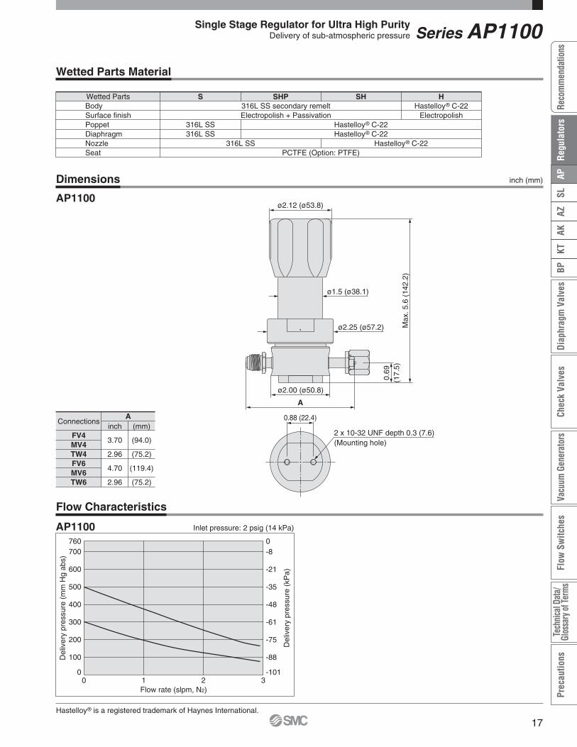
Delivery of sub-atmospheric pressureSingle Stage Regulator for Ultra High Purity
Bonnet option
No codeP
BonnetStandard
Panel installation ∗4)
Code
∗4) Panel mounting hole: dia 1.56inch (39.6 mm).
∗3) PTFE recommended for applications such as within a process tool.
How to Order
AP11 S FV4 FV401 2PW
Seat material
No codeTF
MaterialPCTFE (Standard)
PTFE ∗3)
Code
Surface finish
No codeMVX
Surface finish Ra max15 µin. (0.4 µm) Standard
10 µin. (0.25 µm)7 µin. (0.18 µm)5 µin. (0.13 µm)
Code
Ports
2PW3PW4PW
Ports2 ports3 ports4 ports
Code
Connections (Inletq, Outletw)
FV4MV4TW4FV6MV6TW6
Connections1/4 inch face seal (Female)
1/4 inch face seal (Male)1/4 inch tube weld
3/8 inch face seal (Female)3/8 inch face seal (Male)
3/8 inch tube weld
Code
Port Numberq w e r
Delivery pressure
01Delivery pressure
100 mm Hg absolute to 10 psig (-88 kPa to 0.07 MPa)Code
Gauge port (Inlete, Outletr)
No code
0
LV3
Pressure gauge ∗1)
No gauge portNo pressure gauge
(Connections: 1/4 inch face seal male)
Code psig/bar unit
-30 in.Hg to 60 psig-30 in.Hg to 30 psig
-0.1 to 0.4 MPa-0.1 to 0.2 MPa
MPa unit
Material
Hastelloy®
C-22
Nozzle
316L SS
Diaphragm316L SS
Hastelloy®
C-22
Poppet316L SS
Hastelloy®
C-22
316L SSsecondary
remelt
Body
Hastelloy®
C-22
SSHPSH
H
Code
Pressure gauge unit ∗2)
No codeMPA
Unitpsig/bar
MPa
Code
∗2) Pressure gauge unit MPa or psig/bar selectable.However under Japanese regulation, only MPa isavailable in Japan.
∗1) Other range available. Refer to gauge guide (P.94).
qIN wOUT eGauge port (Inlet)rGauge port (Outlet)
2PW3PW3PW4PW
AP1101Se
V3
w
FV4FV4FV4FV4
q
FV4FV4FV4FV4
r
0V3V3
MPAMPA
Sample Order NumberPort
16
ø2.25 (ø57.2)
ø2.00 (ø50.8)0.
69(1
7.5)
AM
ax.5
.6(1
42.2
)
2 x 10-32 UNF depth 0.3 (7.6)(Mounting hole)
ø1.5 (ø38.1)
0.88 (22.4)
ø2.12 (ø53.8)
Flow Characteristics
Dimensions
AP1100
Hastelloy® is a registered trademark of Haynes International.
Wetted Parts Material
Wetted PartsBodySurface finishPoppetDiaphragmNozzleSeat
S316L SS secondary remeltElectropolish + Passivation
SHP
316L SS
SH HHastelloy® C-22
ElectropolishHastelloy® C-22Hastelloy® C-22
Hastelloy® C-22PCTFE (Option: PTFE)
316L SS316L SS
Connectionsinch (mm)
A
FV4MV4TW4FV6MV6TW6
3.70
2.96
4.70
2.96
(94.0)
(75.2)
(119.4)
(75.2)
Series AP1100Single Stage Regulator for Ultra High PurityDelivery of sub-atmospheric pressure
inch (mm)
0
100
200
300
400
500
600
700
0 1 2 3Flow rate (slpm, N2)
Del
iver
ypr
essu
re(m
mH
gab
s)
-101
-88
-75
-61
-48
-35
-21
-8
Del
iver
ypr
essu
re(k
Pa)
760 0
AP1100 Inlet pressure: 2 psig (14 kPa)
17
AZAK
KTBP
Diap
hrag
mVa
lves
Chec
kVa
lves
Vacu
umGe
nera
tors
Flow
Switc
hes
Tech
nica
lDat
a/Gl
ossa
ryof
Term
sPr
ecau
tions
SLAP
Reco
mm
enda
tions
Reg
ulat
ors

Operating Parameters
Delivery pressure
GasSource pressureFirst stage pressureProof pressure (Inlet)Burst pressureAmbient and operating temperatureCv
Leak rate
Across the seat leakSurface finishConnectionsBonnet portSupply pressure effectInstallationInternal volumeMass
AP17021 to 30 psig
(0.007 to 0.2 MPa)
AP17062 to 60 psig
(0.014 to 0.4 MPa)
AP17102 to 100 psig
(0.014 to 0.7 MPa)Select compatible materials of construction for the gas
Vacuum to 3500 psig (24.1 MPa)175 psig (1.2 MPa)
4000 psig (27.6 MPa)8000 psig (55.2 MPa)
–40 to 160°F (–40 to 71°C) (No freezing) ∗1)
0.052 x 10⁻¹¹ Pa·m3/sec
2 x 10⁻¹⁰ Pa·m3/sec ∗2)
4 x 10⁻⁹ Pa·m3/sec ∗3)
Ra max 15 µin. (0.4 µm) Option: 10 µin. (0.25 µm), 7 µin. (0.18 µm), 5 µin. (0.13 µm)Face seal, Tube weld
NPT 1/8 inch ∗4)
0.05 psig (0.00035 MPa) rise in delivery pressure per 100 psig (0.7 MPa) source pressure dropOption: panel mount0.92 in3 (15.1cm3)
4.50 lbs (2.04 kg) ∗5)
∗1) 14 to 194°F (–10 to 90°C) for Vespel® seat.∗2) Tested with Helium gas inlet pressure 1500 psig (10.5 MPa).∗3) Tested with Helium gas inlet pressure 1000 psig (7 MPa).
∗4) On panel mount option, bonnet port is not threaded.∗5) Mass, including individual boxed weight, may vary depending on connections or options.
Specifications
Porting Configuration
2PW 4PW
w q w q
r e
Inboard leakageOutboard leakage
¡For UHP gas delivery¡High inlet pressure type: Max. 3500 psig (24.1 MPa)¡Body material: 316L SS secondary remelt¡Hastelloy internals available for corrosion resistance¡Minimizes supply pressure effect by two stage regulation¡Tied-diaphragm design
Series AP1700
Low flow(Tied-diaphragm)Two Stage Regulator for Ultra High Purity
Bonnet option
No codeP
BonnetStandard
Panel installation ∗4)
Code
∗4) Panel mounting hole: dia.1.56 inch (39.6 mm).
How to Order
AP17 S FV4 FV402 2PW
Surface finish
No codeMVX
Surface finish Ra max15 µin. (0.4 µm) Standard
10 µin. (0.25 µm)7 µin. (0.18 µm)5 µin. (0.13 µm)
Code
Ports
2PW4PW
Ports2 ports4 ports
Code
Connections (Inletq, Outletw)
FV4MV4TW4FV6MV6TW6
Connections1/4 inch face seal (Female)
1/4 inch face seal (Male)1/4 inch tube weld
3/8 inch face seal (Female)3/8 inch face seal (Male)
3/8 inch tube weld
Code
Seat material
No code
VS
MaterialPCTFE
(Standard)Vespel® ∗3)
Code
∗3) Not available withSH material.
Port Numberq w e r
Delivery pressure
020610
Delivery pressure1 to 30 psig (0.007 to 0.2 MPa)2 to 60 psig (0.014 to 0.4 MPa)
2 to 100 psig (0.014 to 0.7 MPa)
Code
Gauge port (Inlete, Outletr)
No code
0
V3L1H241040
Pressure gauge ∗1)
No gauge portNo pressure gauge
(Connections: 1/4 inch face seal male)
Code
316L SSsecondary
remelt
Material
S
SH
Body Poppet316L SS
Diaphragm316L SS
Nozzle316L SS
Hastelloy®
C-22Hastelloy®
C-22Hastelloy®
C-22
Code
Pressure gauge unit ∗2)
No codeMPA
Unitpsig/bar
MPa
Code
∗2) Pressure gauge unit MPa orpsig/bar selectable. Howeverunder Japanese regulation, only MPa is available inJapan.
∗1) Refer to gauge guide (P.94) for gauge specifications.
qIN wOUT eGauge port (Inlet)rGauge port (Outlet)
psig/bar unit
-30 in.Hg to 30 psig-30 in.Hg to 60 psig-30 in.Hg to 100 psig-30 in.Hg to 160 psig
0 to 200 psig0 to 400 psig0 to 1000 psig0 to 4000 psig
-0.1 to 0.2 MPa-0.1 to 0.4 MPa-0.1 to 0.7 MPa-0.1 to 1.1 MPa
0 to 1.4 MPa0 to 3 MPa0 to 7 MPa0 to 28 MPa
MPa unit
2PW4PW4PW
AP1702Se
040
w
FV4FV4FV4
q
FV4FV4FV4
r
0V3 MPA
Sample Order NumberPort
18

ø2.25 (ø57.2)
A
Max
.7.5
(190
.5)
2.36
(59.
9)
ø1.5 (ø38.1)
INOUT
ø2.12 (ø53.8)
Flow Characteristics
Dimensions
AP1700
Hastelloy® is a registered trademark of Haynes International.Vespel® is a registered trademark of DuPont.
Wetted Parts Material
Connections inch (mm)A
FV4MV4TW4FV6MV6TW6
3.70
2.96
4.70
2.96
(94.0)
(75.2)
(119.4)
(75.2)
Wetted PartsBodySurface finishPoppetDiaphragmNozzleSeat
S316L SS secondary remeltElectropolish + Passivation
316L SS316L SS316L SS
PCTFE (Option: Vespel®)
Hastelloy® C-22Hastelloy® C-22Hastelloy® C-22
PCTFE
SH
Series AP1700Two Stage Regulator for Ultra High PurityLow flow (Tied-diaphragm)
inch (mm)
010
20
30
40
50
60
70
80
90
100
0 50 100 150 200Flow rate (slpm, N2)
Del
iver
ypr
essu
re(p
sig)
0.000.07
0.14
0.21
0.28
0.34
0.41
0.48
0.55
0.62
0.69
Del
iver
ypr
essu
re(M
Pa)
AP1700 Inlet pressure: 200 to 3000 psig (1.4 to 20.7 MPa)
19
AZAK
KTBP
Diap
hrag
mVa
lves
Chec
kVa
lves
Vacu
umGe
nera
tors
Flow
Switc
hes
Tech
nica
lDat
a/Gl
ossa
ryof
Term
sPr
ecau
tions
SLAP
Reco
mm
enda
tions
Reg
ulat
ors

2PW 3PWQMP
MP4PW 5PWQ
Porting Configuration
w q
w qw q
r e r e
w q
Operating Parameters
Delivery pressure
GasSource pressureFirst stage pressureProof pressure (Inlet)Burst pressureAmbient and operating temperatureCv
Leak rate
Across the seat leakSurface finishConnectionsBonnet portSupply pressure effectInstallationInternal volumeMass
AP27021 to 30 psig
(0.007 to 0.2 MPa)Select compatible materials of construction for the gas
Vacuum to 3500 psig (24.1 MPa)200 psig (1.4 MPa)
4000 psig (27.6 MPa)8000 psig (55.2 MPa)
–40 to 160°C (–40 to 71°C) (No freezing) ∗1)
0.1052 x 10⁻¹¹ Pa·m3/sec
2 x 10⁻¹⁰ Pa·m3/sec ∗2)
4 x 10⁻⁹ Pa·m3/sec ∗3)
Ra max 15 µin. (0.4 µm) Option: 10 µin. (0.25 µm), 7 µin. (0.18 µm), 5 µin. (0.13 µm)Face seal, Tube weld
NPT 1/8 inch ∗4)
0.01 psig (0.00007 MPa) rise in delivery pressure per 100 psig (0.7 MPa) source pressure dropOption: panel mount1.87 in3 (30.6 cm3)5 lbs (2.27 kg) ∗5)
AP27062 to 60 psig
(0.014 to 0.4 MPa)
AP27102 to 100 psig
(0.014 to 0.7 MPa)
AP27123 to 120 psig
(0.021 to 0.8 MPa)
Specifications
∗1) 14 to 194°F (–10 to 90°C) for Vespel® seat.∗2) Tested with Helium gas inlet pressure 1500 psig (10.5 Mpa).∗3) Tested with Helium gas inlet pressure 1000 psig (7 MPa).
∗4) On panel mount option, bonnet port is not threaded.∗5) Mass, including individual boxed weight, may vary depending on connections or options.
Inboard leakageOutboard leakage
Series AP2700¡For UHP gas delivery¡High inlet pressure type: Max. 3500 psig (24.1 MPa)¡Flow capacity to 150 slpm (NF3)
to 900 slpm (H2)¡Body material: 316L SS secondary remelt¡Hastelloy internals available for corrosion resistance
¡Minimizes supply pressure effect by two stage regulation
¡Tied-diaphragm design
Bonnet option
No codeP
BonnetStandard
Panel installation ∗4)
Code
∗4) Panel mounting hole:dia. 1.56 inch (39.6 mm).
How to Order
AP27 S FV4 FV402 2PW
Surface finish
No codeMVX
Surface finish Ra max15 µin. (0.4 µm) Standard
10 µin. (0.25 µm)7 µin. (0.18 µm)5 µin. (0.13 µm)
Code
Ports
2PW
3PWQ
4PW
5PWQ
Ports2 ports
4 ports
3 ports(1 pressure monitor port (MP))
5 ports (1 pressure monitor port (MP))
Code
Connections (Inletq, Outletw)
FV4MV4TW4FV6MV6TW6
Connections1/4 inch face seal (Female)
1/4 inch face seal (Male)1/4 inch tube weld
3/8 inch face seal (Female)3/8 inch face seal (Male)
3/8 inch tube weld
Code
Seat material
No code
VS
MaterialPCTFE
(Standard)Vespel® ∗3)
Code
∗3) Not available withSH material.
Port Numberq w e r
Delivery pressure
02061012
Delivery pressure1 to 30 psig (0.007 to 0.2 MPa)2 to 60 psig (0.014 to 0.4 MPa)
2 to 100 psig (0.014 to 0.7 MPa)3 to 120 psig (0.021 to 0.8 MPa)
Code
316L SSsecondary
remelt
Material
S
SH
Body Poppet316L SS
Diaphragm Nozzle316L SS
Hastelloy®
C-22Hastelloy®
C-22
Code
Hastelloy®
C-22
Pressure gauge unit ∗2)
No codeMPA
Unitpsig/bar
MPa
Code
∗2) Pressure gauge unit MPa orpsig/bar selectable. Howeverunder Japanese regulation, only MPa is available inJapan.
Gauge port (Inlete, Outletr)
No code
0
V3L1H241040
Pressure gauge ∗1)
No gauge portNo pressure gauge
(Connections: 1/4 inch face seal male)
Code
Intermediate flow(Tied-diaphragm)Two Stage Regulator for Ultra High Purity
qIN wOUT eGauge port (Inlet)rGauge port (Outlet) MP=Monitoring gauge port
psig/bar unit MPa unit
-30 in.Hg to 30 psig-30 in.Hg to 60 psig-30 in.Hg to 100 psig-30 in.Hg to 160 psig
0 to 200 psig0 to 400 psig0 to 1000 psig0 to 4000 psig
-0.1 to 0.2 MPa-0.1 to 0.4 MPa-0.1 to 0.7 MPa-0.1 to 1.1 MPa
0 to 1.4 MPa0 to 3 MPa0 to 7 MPa0 to 28 MPa
2PW3PWQ4PW
5PWQ
AP2702Se
4040
FV4FV4FV4FV4
FV4FV4FV4FV4
r
V3V3
MPAMPA
Sample Order NumberPort
∗1) Refer to gauge guide (P.94) for gauge specifications.
20

Hastelloy® is a registered trademark of Haynes International.Vespel® is a registered trademark of DuPont.
Dimensions
AP2700
Flow Characteristics
Wetted PartsBodySurface finishPoppetDiaphragmNozzleSeat
S316L SS secondary remeltElectropolish + Passivation
316L SS316L SS / Hastelloy® C-22
316L SSPCTFE (Option: Vespel®)
Hastelloy® C-22Hastelloy® C-22Hastelloy® C-22
PCTFE
SH
Wetted Parts Material
Connectionsinch (mm)
A
FV4MV4TW4FV6MV6TW6
4.30
3.46
5.22
4.00
(109.2)
(87.9)
(132.6)
(101.6)
ø2.12 (ø53.8)
ø1.5 (ø38.1)
ø1.87 (ø47.5)
ø2.62 (ø66.5)
A
Max.10.95(278.1)
2.92
±0.04
(74.2
±1)
2.56
±0.04
(65.0
±1)
4.93
±0.05
(125.2
±1.3)
1.54
±0.04
(39.1
±1)
HPLP
Series AP2700Two Stage Regulator for Ultra High PurityIntermediate flow (Tied-diaphragm)
inch (mm)
0
20
40
60
80
100
0 50 100 150 200 250 300 350Flow rate (slpm, N2)
Deliverypressure(psig)
0.00
0.14
0.28
0.41
0.55
0.69
Deliverypressure(MPa)
AP2700 Inlet pressure: greater than 150 psig (1.0 MPa)
21
AZAK
KTBP
Diap
hrag
mVa
lves
Chec
kVa
lves
Vacu
umGe
nera
tors
Flow
Switc
hes
Tech
nica
lDat
a/Gl
ossa
ryof
Term
sPr
ecau
tions
SLAP
Reco
mm
enda
tions
Reg
ulat
ors

Porting Configuration
2PW 3PW
w q w
e
q
Series AP9000 & 9100
Bulk gas deliverySingle Stage Regulator for Ultra High Purity
¡For UHP gas delivery¡Inlet pressure AP9000: Max. 1700 psig (11.7 MPa) AP9100: Max. 800 psig (5.5 MPa)¡Flow capacity AP9000: to 2000 slpm
AP9100: to 5000 slpm
How to Order
AP9 S FV16 FV160 2PW
Surface finish
No codeM
Surface finish Ra max15 µin. (0.4 µm)10 µin. (0.25 µm)
CodePorts
2PW3PW
Ports2 ports3 ports
Code
Connections (Inletq, Outletw)
FV8MV8TW8FV12MV12TW12FV16MV16TW16
Connections1/2 inch face seal (Female)
1/2 inch face seal (Male)1/2 inch tube weld
3/4 inch face seal (Female)3/4 inch face seal (Male)
3/4 inch tube weld1 inch face seal (Female)
1 inch face seal (Male)1 inch tube weld
Code
Seat material
No codeVS
MaterialPCTFE (Standard)
Vespel®
Code
Port Numberq w e
Size
01
Cv34
Code
Gauge ports (Outlete)
No code
0
V3L1H4
Pressure gauge∗1)
No gauge port
Code
Material
SCode Material
316L SS
101530
Delivery pressure
5 to 100 psig (0.034 to 0.7 MPa)5 to 150 psig (0.034 to 1.0 MPa)
Preset to 300 psig (2.1 MPa)
Size0V
V
1VV
Code
No pressure gauge(Connections: 1/4 inch face seal male)
Operating Parameters
Delivery pressure
Gas
Source pressure
Proof pressure (Inlet)Burst pressureAmbient and operating temperatureCv
Leak rate
Across the seat leakSurface finishConnectionsBonnet port
Supply pressure effect
Internal volumeMass
Vacuum to 1700 psig(11.7 MPa)
5 to 100 psig(0.034 to 0.7 MPa)
AP9010
2550 psig (17.6 MPa)6800 psig (46.9 MPa)
–40 to 160°C (–40 to 71°C) (No freezing) ∗2)
2 x 10-11 Pa·m3/sec2 x 10-10 Pa·m3/sec ∗3)
4 x 10⁻⁹ Pa·m3/sec ∗3)
Ra max 15 µin (0.4 µm) or 10 µin (0.25 µm)Face seal, Tube weld
NPT 1/8 inch
12 in3 (197 cm3)13 lbs (5.9 kg) ∗4)
Preset to 300 psig(2.1 MPa) ∗1)
AP9030
Vacuum to 800 psig(5.5 MPa)
5 to 100 psig(0.034 to 0.7 MPa)
AP9110
Vacuum to 250 psig(1.7 MPa)
5 to 150 psig(0.034 to 1.0 MPa)
AP9115
Specifications
3.0 4.0
3.7 psig (0.026 MPa) rise in delivery pressure per100 psig (0.7 MPa) source pressure drop
5.4 psig (0.038 MPa) rise in delivery pressure per100 psig (0.7 MPa) source pressure drop
Pressure gauge unit ∗2)
No codeMPA
Unitpsig/bar
MPa
Code
Select compatible materials of construction for the gas
∗2) Pressure gauge unit MPa orpsig/bar selectable. Howeverunder Japanese regulation, onlyMPa is available in Japan.
∗1) Refer to gauge guide (P.94) for gauge specifications.
qIN wOUT eGauge port (Outlet)
∗1) At 800 psig (5.5 MPa) inlet pressure. Optional preset pressure available. Please contact SMC.∗2) 14 to 194°F (–10 to 90°C) for Vespel® seat.∗3) Tested with Helium gas inlet pressure 300 psig (2.1 MPa).∗4) Mass, including individual boxed weight, may vary depending on connections or options.
Inboard leakageOutboard leakage
2PW3PW
AP9010Se
H
w
FV12FV12
q
FV12FV12 MPA
Sample Order NumberPort
psig/bar unit
-30 in.Hg to 30 psig-30 in.Hg to 60 psig-30 in.Hg to 100 psig-30 in.Hg to 160 psig
0 to 400 psig
-0.1 to 0.2 MPa-0.1 to 0.4 MPa-0.1 to 0.7 MPa-0.1 to 1.1 MPa
0 to 3 MPa
MPa unit
10
Delivery pressure
¡Body material: 316L SS¡Tied-diaphragm design
22

ø4.00 (ø101.6)
ø3.5 (ø88.9)
1.5 (38.1)
AA
Max
.11.
2(2
84.5
)
5.38
(136
.7)
1.13
(28.
7)
2 x 1/4-20 UNC depth 0.35 (8.9)(Mounting hole)
HPLP
3.5 (89)
ø0.
75(ø
19)
Flow Characteristics
Hastelloy® is a registered trademark of Haynes International.Elgiloy® is a registered trademark of Elgiloy Specialty Metals.Vespel® is a registered trademark of DuPont.
Wetted Parts Material
Wetted PartsBodySurface finishPoppetBellowsNozzleSeatPoppet springBonnet seal
S316L SS
Electropolish + PassivationHastelloy® C-22Hastelloy® C-22
316L SSPCTFE (Option: Vespel®)
Elgiloy®
Nickel 200 ∗) (Silver plated)
Dimensions
AP9000 & 9100
Connectionsinch (mm)
A
FV8MV8TW8FV12MV12TW12FV16MV16TW16
3.11
4.75
3.64
4.75
3.92
4.75
(79.0)
(120.7)
(92.5)
(120.7)
(99.6)
(120.7)
Series AP9000 & 9100Single Stage Regulator for Ultra High PurityBulk gas delivery
inch (mm)
0
50
100
150
200
250
300
0 200 400 600 800 1000 1200 1400 1600 1800 2000Flow rate (slpm, N2)
Del
iver
ypr
essu
re(p
sig)
0.0
0.3
0.7
1.0
1.4
1.7
2.1
Del
iver
ypr
essu
re(M
Pa)
0
10
20
30
40
50
60
70
80
90
0 200 400 600 800 1000 1200 1400 1600 1800 2000Flow rate (slpm, N2)
Del
iver
ypr
essu
re(p
sig)
0.00
0.07
0.14
0.21
0.28
0.34
0.41
0.48
0.55
0.62
Del
iver
ypr
essu
re(M
Pa)
0
10
20
30
40
50
60
70
80
90
0 500 1000 1500 2000 2500 3000 3500 4000 4500 5000Flow rate (slpm, N2)
Del
iver
ypr
essu
re(p
sig)
0.00
0.07
0.14
0.21
0.28
0.34
0.41
0.48
0.55
0.62
Del
iver
ypr
essu
re(M
Pa)
AP9030 600 psig (4.1 MPa)Inlet pressure:
AP90101000 psig (6.9 MPa)200 psig (1.4 MPa)
Inlet pressure: 300 psig (2.1 MPa)75 psig (0.52 MPa)
AP9110 150 psig (1.0 MPa)Inlet pressure: 75 psig (0.52 MPa)
∗) 316 SS silver plated for AP9030
23
AZAK
KTBP
Diap
hrag
mVa
lves
Chec
kVa
lves
Vacu
umGe
nera
tors
Flow
Switc
hes
Tech
nica
lDat
a/Gl
ossa
ryof
Term
sPr
ecau
tions
SLAP
Reco
mm
enda
tions
Reg
ulat
ors