series boom & patient lift pendant (plp) system
TRANSCRIPT

Installation and Operation Instructions
Series Boom & Patient Lift Pendant (PLP) System

2 Amico Clinical Solutions Corp.
Contents
Introduction 3-5Symbols Used in this Manual 4Markings 4Amico Booms - Patient Lift Pendant (PLP), OR, and iCE Series Equipment Storage, Shipping, and Operating Environment 5
Patient Lift Pendant (PLP) System 6-8Operation of the Arm 7 Moving the Arm 8How the Brakes Operate 8Precautions When Repositioning the Arm 8
Maintenance of the Service Console 9-10Medical Gas Outlets 9 NFPA-99 (2005) 10 CSA – 9170 - 1 10Electrical Outlets 10
Maintenance of the Arm 11-27Anchor Plate 11Ceiling Bearing Flange 11Mounting Bolts 12End Caps 13Arms 14Electric Brake System 14-15Replacing the Electric Brake Handle 16-22 Replacing the Ribbon Cable 18-21Brake Pad Inspection 22-23Replacing the Adaptor/Console Brake Shoe 24Replacing the Ceiling Brake Shoe 24-25Adjusting Brake Shoe (Adapter/Console/Ceiling) 25-26Replacing the Ceiling Solenoid 26
Adapter and Console 27-29Adapter and Console 27Rotational Limiters 27Interior Hoses and Cabling 28Cleaning and Disinfection 28 Recommended Cleaning Agents 28Troubleshooting 28
Guidance and Manufacturer’s Declaration – Electromagnetic Emissions 30-32Electromagnetic Compliance Data for Amico Boom and Pendant 30-32Recommended Separation Distances Between Portable and Mobile RF Communications Equipment and the Equipment or System 32Disposal 32
Warranty Policy - Booms/Pendants 33

www.amico.com 3
Thank you for choosing the Amico iCE Series Boom or Patient Lift Pendant (PLP) System.
The Amico Clinical Solutions (ACS) Booms and PLP Systems are hospital grade medical pendants, intended for use in a non-classified (non-hazardous) indoor location, and permanently mounted to the building structure.
Essential Performance
The iCE Boom provides convenient connection to electrical power through medical grade outlets, medical-grade gases like medical air, oxygen, etc., and vacuum to other equipment (mountable on the aluminum channels provided on the four edges of the console using adapter brackets), when connected to appropriate sources generally available in hospitals. Essential performance is checked/tested following the tests specified by ISO 7396-1:2007.
Intended User Profile
• Amico Booms are intended to be used by trained medical practitioners in operating rooms, procedure rooms, emergency departments, and intensive care units.
• The user must be able to read the words in the mylar control and wall control to operate the Boom and Pendant.
• The user must be able to understand the Instructions for Use manual and the training provided by Amico sales staff (or other designated personnel).
• User has to be able to position the Amico Pendant by pressing the appropriate button on the handle.
Intended Use
• To provide the facility with convenient connection to electrical power (through medical grade outlets), medical gases and other equipment mounted on the shelves.
Patient Population
a. Age: newborn, bariatric, and geriatric
b. Weight: not relevant
c. Health: not relevant
d. Nationality: multiple
e. Patient state: patient is not a user
Application
a. Environment: the Amico Boom is intended to be used in the operating rooms, procedure rooms, emergency departments, and intensive care units.
b. Physical: see Environmental Conditions section.
c. Frequency of use: several times a day.
d. Mobility: central Axis is fixed to the supporting structure but the extension arm and spring arm can be move so as to position the surgical light to illuminate the operating field.
e. Training: training provided by Amico sales staff (or other designated personnel) via hands-on demonstration of the equipment along with the Instructions for Use. There are no known contradictions associated with the use of the Amico Series Boom and Pendant and its accessories provided they are used per our recommendations and guidelines.
Introduction

4 Amico Clinical Solutions Corp.
Introduction
Symbols Used in this Manual
Symbol Reference Title
! ISO 7000-0434A Caution - Risk of danger
TUV Certified by TUV
ISO-7010-M002 Refer to instruction manual/booklet
CE Certification of Conformity
! WARNING: Failure to adhere to these instructions may result in damages to equipment or injury to users.
Markings
The Amico Boom and Pendants are designed to comply with the following standards:
Standard(s): EMC to IEC 60601-1-2 4th edition
EN 60601-1:2006/A1:2013
EN ISO14971:2012
EN ISO 11197:2016
CAN/CSA-C22.2 No. 60601-1:2014:03
ANSI/AAMI ES60601-1:2005/A1:2012
Product: Amico Series Boom and Pendant
Brand Name: Amico
Models: LP, PLP
! WARNINGS
• Do not use this equipment prior to understanding the contents of this manual. Keep this manual for future reference.
• To avoid the risk of electric shock, this equipment must only be connected to supply mains with protective earth.
• Do not modify this equipment without authorization from ACS.
• Only connect accessories that are compatible with the Amico Boom and Pendant System.
• Connecting equipment to the Multiple Socket-Outlet (MSO) effectively leads to creating a Medical Equipment (ME) System and the result can be a reduced level of safety.
• Only personnel that have been trained by ACS may perform installation of this product.
• Maximum rating of fuses (breaker) used in supply mains is 20 A.
• To terminate the operation of the equipment, turn off the breaker at the panel.
• Do not locate an additional multiple socket item when provided as a separate item on the floor.
• Do not connect additional MSO or extension cords to the Boom and Pendant.
• Operator should not touch part mains and the patient simultaneously.

www.amico.com 5
RH20% - 90%
P700hPa - 1060hPa-10°C
(14°F)
+50°C(122°F)
Temperature range for
transport and storage
Atmospheric humidity for
transport and storage
700 hPa - 1060 hPa-10oC
Air pressure for transport and
storage
Introduction
Amico Booms - Patient Lift Pendant (PLP), OR, and iCE Series Equipment Storage, Shipping, and Operating Environment
Operation
Minimum Maximum
Temperature +10oC +30oC
Relative Atmospheric Humidity 30% 75%
Air Pressure 700 hPa 1060 hPa
Amico Equipment is designed to withstand the elements during its life installed in a controlled hospital environment. During storage, however, the environmental conditions can vary due to transportation and storage locations. Below are a set of rules that must be followed to prevent damage to the product and maximize product life:
1. Amico product must NOT be stored in a damp or wet environment with no protection against the elements. The Warranty will be void if these rules are not followed.
2. Always ensure the packaging is not damaged when storing product for long term. Patch the packaging (bubble wrap, shrink wrap) if punctured.
3. Storage/Transport conditions with length of period less than 1 month are as follows:
a. Temperature = +10oC to +40oC
b. Relative Humidity = 20% to 90%
+50oC

6 Amico Clinical Solutions Corp.
Patient Lift Pendant (PLP) System
Amico offers a PLP option that integrates Booms, Pendants and Safe Patient Handling into one comprehensive system. The unique design frees up ceiling space for proper pendant placement, and medical lighting. This system can safely lift up to 1000 lbs (454 kg).
The PLP integrates equipment rails positioned on the Boom and Pendant consoles. The end user is also able to choose from a wide range of accessories to enhance their pendant system.

www.amico.com 7
Equipment Transport System (ETS)
Operation of the Arm
Moving the Arm:
1. To begin moving Amico’s Boom arm, locate the electric brake handle that is mounted on the service console.
2. Press and hold button to move the boom.
3. The green LED light on the handle will illuminate to indicate you have successfully released the brake.
Electric Brake Handles
Press and hold Button Two 2 to release
the Second Arm of the Boom AND the Console.
Press and hold Button All All to release all Arms controlled by Buttons One 1 and Two 2 and the Console.
Button One
Button Two
Button All
First Arm
Second Arm & Console
All Arms & Console
1
1
2
2
All
All = +
Press and hold Button One 1 to release the First Arm of the Boom.

8 Amico Clinical Solutions Corp.
Equipment Transport System (ETS)
How the Brakes Operate
Amico Booms have one (1) solenoid mounted at each bearing. The solenoid disengages and re-engages the braking mechanism. When the arm is stationary with no buttons activated, the brake remains fully engaged. This prevents accidental repositioning of the console and arms.
In dual arm systems, in order to reposition the first arm, press and hold the “One (1)” button as indicated on the handle. A green LED light will then illuminate to indicate that the ceiling bearing brake has been released. When pressing the “Two (2)” button, the adapter bearing and service console bearing brakes will be released. To move “All” of the arm(s) and the service console, depress the ‘All’ button. This will allow the full system to be positioned freely.
Precautions When Repositioning the Arm
! WARNING:
1. Prior to moving the Boom, ensure ALL equipment is secured.
2. Be sure all obstacles are removed out of the path before moving the arm.
It is important to remember that even when the brake handle buttons are activated, once the unit has reached its maximum rotation, it will not move any further in that particular direction.
In the event of an emergency, the arms may be manually pushed out of the way without the requirement of pressing the brake release button.
! WARNING:
Amico highly recommends manual maneuvering of the arm is only done in the event of an emergency, as pushing the arms without releasing the brake will cause undue stress on the braking system.
NOTE: Do not conduct any maintenance/service of parts while the equipment is in use with a patient.
M16 Threaded Rod
Boom with Solenoid Mounted at Each Bearing
www.amico.com 9
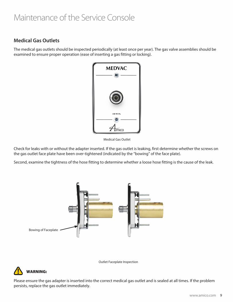
Medical Gas Outlets
The medical gas outlets should be inspected periodically (at least once per year). The gas valve assemblies should be examined to ensure proper operation (ease of inserting a gas fitting or locking).
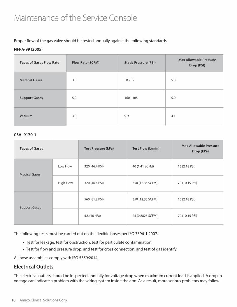
Check for leaks with or without the adapter inserted. If the gas outlet is leaking, first determine whether the screws on the gas outlet face plate have been over-tightened (indicated by the “bowing” of the face plate).
Second, examine the tightness of the hose fitting to determine whether a loose hose fitting is the cause of the leak.
! WARNING:
Please ensure the gas adapter is inserted into the correct medical gas outlet and is sealed at all times. If the problem persists, replace the gas outlet immediately.
Maintenance of the Service Console
Bowing of Faceplate
Medical Gas Outlet
Outlet Faceplate Inspection
10 Amico Clinical Solutions Corp.
Maintenance of the Service Console
Proper flow of the gas valve should be tested annually against the following standards:
NFPA-99 (2005)
Types of Gases Flow Rate Flow Rate (SCFM) Static Pressure (PSI)Max Allowable Pressure
Drop (PSI)
Medical Gases 3.5 50 - 55 5.0
Support Gases 5.0 160 - 185 5.0
Vacuum 3.0 9.9 4.1
CSA–9170-1
Types of Gases Test Pressure (kPa) Test Flow (L/min)Max Allowable Pressure
Drop (kPa)
Medical Gases
Low Flow 320 (46.4 PSI) 40 (1.41 SCFM) 15 (2.18 PSI)
High Flow 320 (46.4 PSI) 350 (12.35 SCFM) 70 (10.15 PSI)
Support Gases
560 (81.2 PSI) 350 (12.35 SCFM) 15 (2.18 PSI)
5.8 (40 kPa) 25 (0.8825 SCFM) 70 (10.15 PSI)
The following tests must be carried out on the flexible hoses per ISO 7396-1:2007.
• Test for leakage, test for obstruction, test for particulate contamination.
• Test for flow and pressure drop, and test for cross connection, and test of gas identify.
All hose assemblies comply with ISO 5359:2014.
Electrical Outlets
The electrical outlets should be inspected annually for voltage drop when maximum current load is applied. A drop in voltage can indicate a problem with the wiring system inside the arm. As a result, more serious problems may follow.
www.amico.com 11
Maintenance of the Arm
Anchor Plate
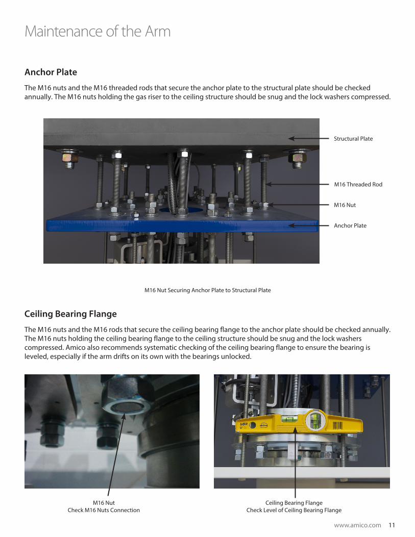
The M16 nuts and the M16 threaded rods that secure the anchor plate to the structural plate should be checked annually. The M16 nuts holding the gas riser to the ceiling structure should be snug and the lock washers compressed.
Ceiling Bearing Flange
The M16 nuts and the M16 rods that secure the ceiling bearing flange to the anchor plate should be checked annually. The M16 nuts holding the ceiling bearing flange to the ceiling structure should be snug and the lock washers compressed. Amico also recommends systematic checking of the ceiling bearing flange to ensure the bearing is leveled, especially if the arm drifts on its own with the bearings unlocked.
Structural Plate
Anchor Plate
M16 Nut
M16 Threaded Rod
Ceiling Bearing FlangeCheck Level of Ceiling Bearing Flange
M16 NutCheck M16 Nuts Connection
M16 Nut Securing Anchor Plate to Structural Plate

12 Amico Clinical Solutions Corp.
Mounting Bolts
Check all bolts in the adapter bearing holding the top and bottom arm.
To inspect for damages of the drop tube and the console, lift the console top cover upward by removing the nut from the threaded rods on the inside of the console. This method of inspection also ensures any gaps between the console flange and console top are eliminated. Should a gap occur, please ensure the screws mounting the console top to the console flange are fully tightened.
Maintenance of the Arm
M8 Allen Bolts ScrewsThe Screws Connecting the Service
Console to Drop Tube
Bolts Securing Bearing to Arm
Console Flange
Console Top
Checking for Gaps Between the Console Flange

www.amico.com 13
Maintenance of the Arm
End Caps
Attach one (1) end cap to one side of the arm and the other end cap to the other side of the arm. There are four (4) magnets inside the end cap. Ensure the magnets align with the two (2) bolts and the two (2) metal bars installed at each end of the arm. Additionally, a secure ring clip should also be placed around one of the gas hoses.
Two (2) Bolts
End Cap
Two (2) Metal Bars
Secure Ring Clip
Boom Arm with the End Cap Attached

14 Amico Clinical Solutions Corp.
Maintenance of the Arm
Arms
The bearings of the arms and service console should be checked annually for movement when the brake is activated. The arm should also be checked to ensure it is level.
Electric Brake System
Inspection for the wiring or the electric brake must be made on an annual basis to ensure proper connection. Systematic inspection of the electric brake will also reduce the potential of a short circuit to the system.
First Arm of Boom
Ensure the first Arm is leveled
Level
CEILING LINE
ADAPTER
CONSOLE
6A
ELECTRIC BRAKE POWER SUPPLY BOX SUPPLIED BY AMICO.EACH BOOM REQUIRES 6 AMP FOR OPERATION. 12 AMPS FORTWO BOOMS.POWER TO BE PROVIDED BY HOSPITAL
***NOT FOR CIRCUITS FOR CONSOLES ***
MAIN FEED JUNCTION BOX FORBOOM RECEPTACLES CIRCUITSPROVIDED & INSTALLED BYHOSPITAL
Distance off the edge of structure Min 1 ft Max 2ft
Distance above the ceilingMin 12" Max 18"
JUNCTIONBOX
CONSOLEDRAWINGS
BOOMPOWERSUPPLY
upper
lower
upper +
lower
ELEC
TRIC
BR
AKE
ELECTRIC WIRING DIAGRAM
PAGE:
-QUANTITY:
PROJECT NAME:
GENERIC DUAL PLATEANESTHESIA BOOM
EQUIP. TYPE:
-
ROOM TYPE/NO:
-QUOTE #:
-
w w w . a m i c o . c o m
Connect PE from junction box to the welded stud in the power supply box.
www.amico.com 15
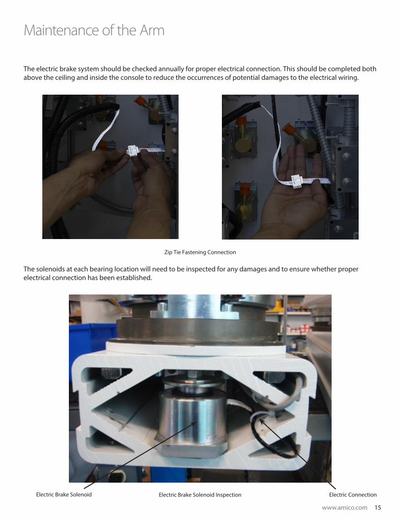
The electric brake system should be checked annually for proper electrical connection. This should be completed both above the ceiling and inside the console to reduce the occurrences of potential damages to the electrical wiring.
The solenoids at each bearing location will need to be inspected for any damages and to ensure whether proper electrical connection has been established.
Maintenance of the Arm
Zip Tie Fastening Connection
Electric Brake Solenoid InspectionElectric Brake Solenoid Electric Connection
16 Amico Clinical Solutions Corp.
Maintenance of the Arm
Replacing the Electric Brake Handle
To begin the electric brake handle replacement, please follow the steps below:
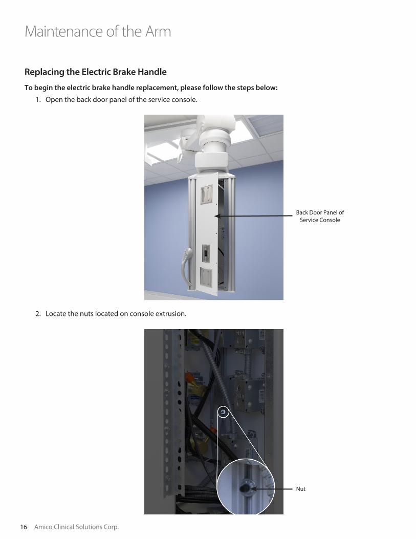
1. Open the back door panel of the service console.
2. Locate the nuts located on console extrusion.
Back Door Panel of Service Console
Nut

www.amico.com 17
3. Using 5/16 sockets, remove the two (2) nuts that are holding the assembly.
4. Pull the handle assembly out and disconnect the ribbon cable assembly from the mylar.
Maintenance of the Arm
5/16 Sockets

18 Amico Clinical Solutions Corp.
5. Locate the replacement handle.
Replacing the Ribbon Cable:
Maintenance of the Arm
To begin replacing the ribbon cable, please follow the steps below:
a. Cut the ribbon cable.
b. Pull the ribbon cable out of the corner extrusion.
Corner Extrusion
Ribbon Cable
Ribbon Cable to Handle

www.amico.com 19
Maintenance of the Arm
c. Locate the spare ribbon cable and connector assembly. Clean with Acetone.
d. Take the ribbon cable and pull it through the corner extrusion hole.
e. Once through, the next step is to crimp the second (2nd) connector onto the ribbon cable.
f. To ensure proper crimping, locate the notch.
Corner Extrusion Hole
Second (2nd) Connector
Spare Ribbon Cable
Corner Extrusion Hole
Notch
Grooves

20 Amico Clinical Solutions Corp.
g. Align the notch with the red/pink segment of the cable.
h. Using a crimping tool, squeeze the two (2) halves while ensuring ribbon cables are seeded in the grooves of the connector.
i. Reconnect the new handle ribbon cable to the main ribbon cable. Check to ensure solenoid actuation by pressing all three (3) buttons one after another.
Maintenance of the Arm
www.amico.com 21
Maintenance of the Arm
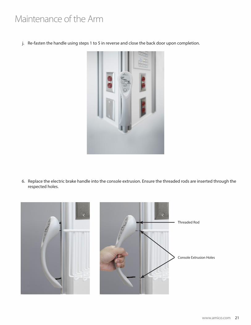
j. Re-fasten the handle using steps 1 to 5 in reverse and close the back door upon completion.
Threaded Rod
Console Extrusion Holes
6. Replace the electric brake handle into the console extrusion. Ensure the threaded rods are inserted through the respected holes.

22 Amico Clinical Solutions Corp.
7. Using the flat washer and nylon nut, fasten the handle onto the console extrusion.
8. Test to ensure full functionality.
9. Close the service console upon completion.
Maintenance of the Arm
Brake Pad Inspection
At each bearing location, the brake shoes must be disassembled to inspect the brake pad for any signs of damages.
Steps to disassemble the brake shoes are as follows:
1. Remove the bearing cover.
a. Remove the two (2) M3 screws.
M3 Screws

www.amico.com 23
b. Press at the seam to disassemble the bearing cover.
2. Carefully remove the spring with a spring tool.
3. Open the brake shoes to reveal the brake pad.
Maintenance of the Arm
Brake Pad

24 Amico Clinical Solutions Corp.
Replacing the Adaptor/Console Brake Shoe
1. On the adaptor/console remove the bearing cover (refer to step one (1) in Replacing Electric Brake Handle).
2. Carefully remove the spring with a spring tool (refer to step two (2) in Brake Pad Inspection).
3. Replace the brake shoes (refer to Adjusting Brake Shoes).
4. Clean the brake pad with Acetone
5. Inspect for cuts or rips in the brake pad.
6. If cuts or rips are observed, please document (through photos) and contact ACS for replacement and instructions on replacement of brake shoe. An example of a damaged brake shoe shown below.
7. Follow steps 1 through 3 in reverse to re-assemble the brake.
Replacing the Ceiling Brake Shoe
1. Access the ceiling brake shoes through the drop ceiling/access panel.
2. Carefully remove the spring with a spring tool.
3. Locate the shoulder bolts on brake hinge. Using a 4 mm Allen key remove one of the brake shoes.
Maintenance of the Arm
Shoulder Bolts

www.amico.com 25
Adjusting Brake Shoe (Adapter/Console/Ceiling)
1. Ensure brake shoes are closed and the spring is in place.
2. Confirm the set screws are loose.
3. By using a flathead screwdriver, begin to tighten the screw such that the head of the screw moves closer towards the slider assembly.
Maintenance of the Arm
Set Screw
4. Next, by using a 6 mm Allen key remove the two M8 screws holding the hinge down.
5. Remove the complete brake shoe assembly.
6. Locate the replacement shoes and following the steps 1 through 4 in reverse to re-assemble the brake.
26 Amico Clinical Solutions Corp.
Maintenance of the Arm
! NOTE:
If you have trouble turning the screw using the screwdriver or have an older style screw, please adjust by using a 10 mm wrench or spanner.
4. Discontinue turning once the screw is touching the slider body.
5. Repeat steps 2 to 4 for the second brake shoe.
6. Check for brake strength and movement of the arms. If movement of arm with the brakes disengaged is tight and or if a squeaking sound can be heard, turn screws closer in towards the slider body. Check for brake strength and movement and repeat this process until requirement is met.
! NOTE:
Ensure solenoid actuation is present. If not, turn the screw such that the head moves away from the slider body until actuation is present.
! NOTE:
If no solenoid actuation is present despite contact of screws to the slider body, check for magnetism of the solenoid by touching a steel component to the solenoid body. If no magnetism is present, contact Amico Clinical Solutions for assistance. Make sure finger is clear of solenoid before trying to activate.
7. Once the desired movement and strength is achieved, tighten the set screws and clean up any debris present.
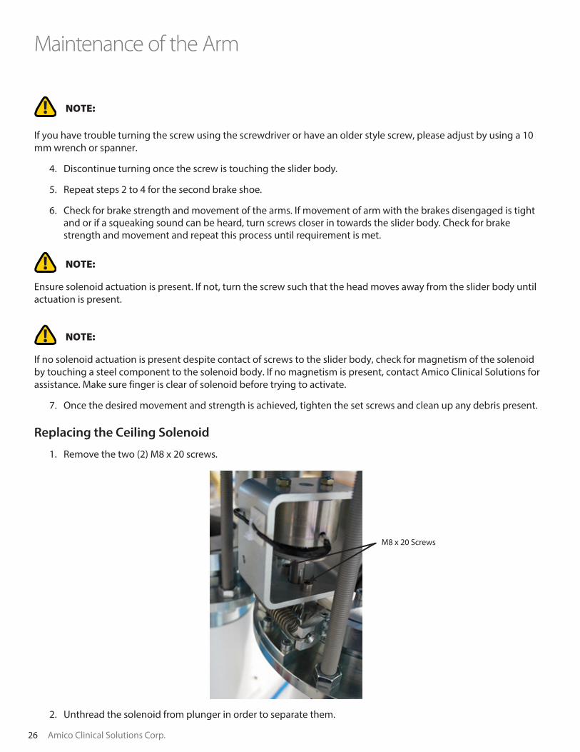
Replacing the Ceiling Solenoid
1. Remove the two (2) M8 x 20 screws.
2. Unthread the solenoid from plunger in order to separate them.
M8 x 20 Screws

www.amico.com 27
Adapter and Console
1. Remove the two (2) M8 screws that secure the solenoid in place.
2. Remove the sound absorbent pad.
3. Turn the solenoid plunger in counterclockwise direction until the rod is loose by squeezing the solenoid plunger closer to the solenoid body.
4. Replace the sound absorbent pad.
5. Replace the solenoid plunger by rotating it clockwise until the rod is tightened.
6. Replace the two (2) screws to secure the solenoid.
Rotational Limiters
The Allen set screws that hold the rotational limiters must be checked annually for wear and tear.
Adapter and Console
Solenoid Plunger
(Adapter)
Solenoid Plunger (Ceiling)
Rotational Limiter
Two (2) M8 screws
28 Amico Clinical Solutions Corp.
Adapter and Console
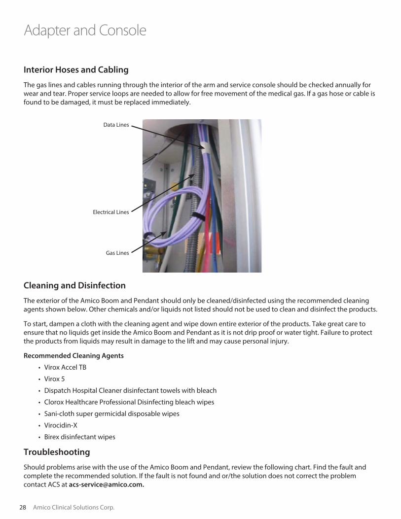
Interior Hoses and Cabling
The gas lines and cables running through the interior of the arm and service console should be checked annually for wear and tear. Proper service loops are needed to allow for free movement of the medical gas. If a gas hose or cable is found to be damaged, it must be replaced immediately.
Cleaning and Disinfection
The exterior of the Amico Boom and Pendant should only be cleaned/disinfected using the recommended cleaning agents shown below. Other chemicals and/or liquids not listed should not be used to clean and disinfect the products.
To start, dampen a cloth with the cleaning agent and wipe down entire exterior of the products. Take great care to ensure that no liquids get inside the Amico Boom and Pendant as it is not drip proof or water tight. Failure to protect the products from liquids may result in damage to the lift and may cause personal injury.
Recommended Cleaning Agents
• Virox Accel TB
• Virox 5
• Dispatch Hospital Cleaner disinfectant towels with bleach
• Clorox Healthcare Professional Disinfecting bleach wipes
• Sani-cloth super germicidal disposable wipes
• Virocidin-X
• Birex disinfectant wipes
Troubleshooting
Should problems arise with the use of the Amico Boom and Pendant, review the following chart. Find the fault and complete the recommended solution. If the fault is not found and or/the solution does not correct the problem contact ACS at [email protected].
Electrical Lines
Gas Lines
Data Lines

www.amico.com 29
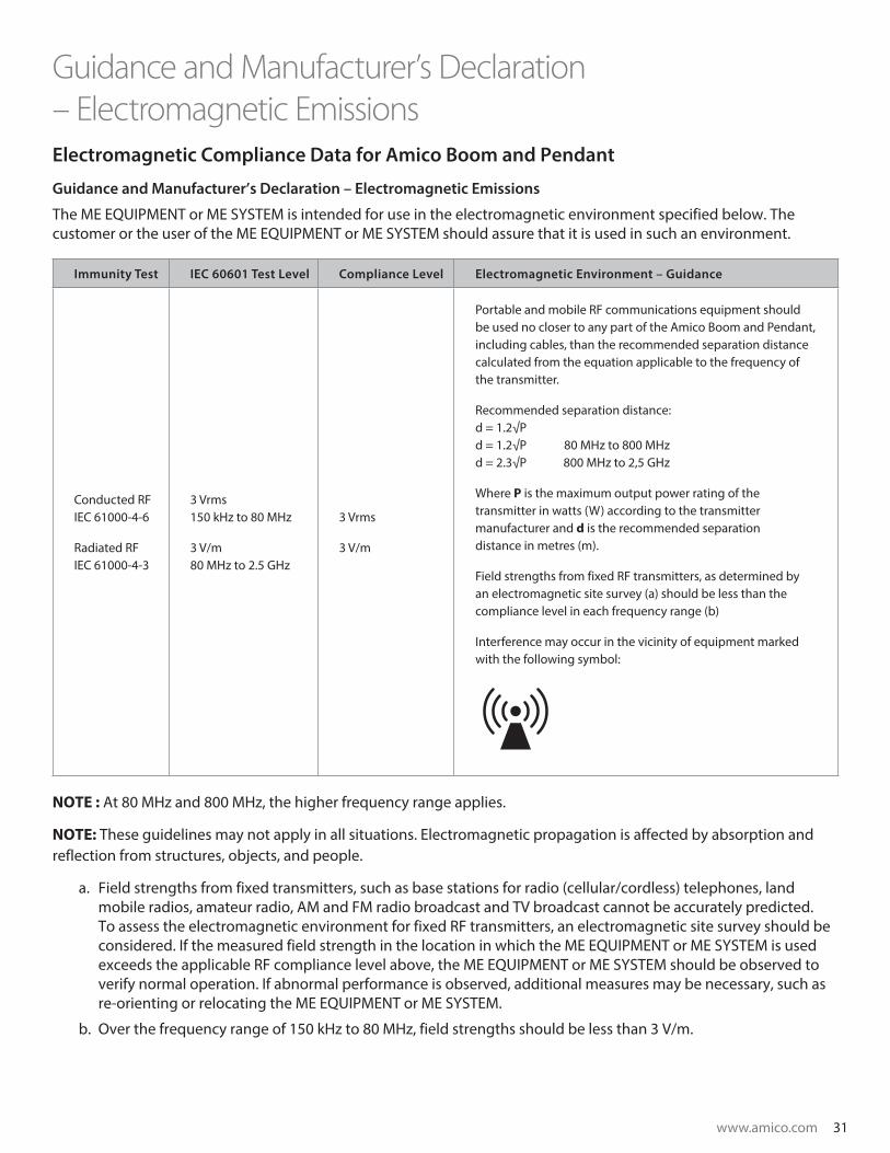
Electromagnetic Compliance Data for Amico Boom and Pendant
Guidance and Manufacturer’s Declaration – Electromagnetic Emissions
The equipment or system is intended for use in the electromagnetic environment specified below. The customer or the user of the equipment or system should assure that it is used in such an environment.
Fault Recommended Solution
If the handle controls fail to operate. In an emergency, move the arms with the brakes engaged.
If the brakes are not working properly. The pads may need to be replaced, if this is the case, contact ACS.
If there is a gas leak in the system. Shutdown power and perform a leak test.
Boom and Pendant is intended for use in the electromagnetic environment specified below. The customer or the user of the Amico Boom and Pendant should assure that it is used in such an environment.
Emissions Compliance Electromagnetic Environment - Guidance
RF Emissions
CISPR 11 Group 1
The Amico Boom and Pendant uses RF energy only for its internal
function. Therefore, its RF emissions are very low and are not likely to
cause any interference in nearby electronic equipment.
RF Emissions
CISPR 11 Class A
The Amico Boom and Pendant is suitable for use in all establishments
other than domestic establishments and those directly connected to
the public low-voltage power supply network that supplies buildings
used for domestic purposes.
Harmonic Emissions
IEC 61000-3-2 Class A
Voltage Fluctuations / Flicker
Emissions
IEC 61000-3-3
Complies
Guidance and Manufacturer’s Declaration – Electromagnetic Emissions

30 Amico Clinical Solutions Corp.
Electromagnetic Compliance Data for Amico Boom and Pendant
Guidance and Manufacturer’s Declaration – Electromagnetic Emissions
The Amico Boom and Pendant is intended for use in the electromagnetic environment specified below. The customer or the user of the Amico Boom and Pendant should assure that it is used in such an environment.
Immunity Test IEC 60601 Test Level Compliance Level Electromagnetic
Environment – Guidance
Electrostatic Discharge (ESD)IEC 61000-4-2
±6 kV contact
±8 kV air
±6 kV contact
±8 kV air
Floors should be wood, concrete, or ceramic tile. If floors are covered with synthetic material, the relative humidity should be at least 30%.
Electrical Fast Transient/Burst IEC 61000-4-4
±2 kV for power supply lines
±1 kV for input/output lines
±1 kV for power supply lines
±0.250 kV for input/output lines
The Main power supply quality should be that of a typical commercial or hospital environment.
Surge IEC 61000-4-5
±1 kV line(s) to line(s)
±2 kV line(s) to earth
±1 kV line(s) to line(s)
±2 kV line(s) to earth
Main power quality should be that of a typical commercial or hospital environment.
Voltage Dips, Short Interruptions, and Voltage Variations on Power Supply Input Lines IEC 61000-4-11
<5% UT (>95% dip in UT) for 0,5 cycle
40% UT (60% dip in UT) for 5 cycles
70% UT (30% dip in UT) for 25 cycles
<5% UT (>95% dip in UT) for 5 sec
<5 % UT (>95% dip in UT) for 0,5 cycle
40 % UT (60% dip in UT) for 5 cycles
70 % UT (30% dip in UT) for 25 cycles
<5 % UT (>95% dip in UT) for 5 sec
The Main power supply quality should be that of a typical commercial or hospital environment.
If the user of the Amico Boom and Pendant requires continued operation during main power interruptions, it is recommended that the Amico Boom and Pendant be powered from an interruptible power supply or a battery.
Power Frequency (50/60 Hz) Magnetic Field IEC 61000-4-8
3 A/m Not Applicable
Power frequency magnetic fields should be at levels characteristic of a typical commercial or hospital environment.
NOTE: UT is the A.C. mains voltage prior to application of the test level.
Guidance and Manufacturer’s Declaration – Electromagnetic Emissions
www.amico.com 31
Guidance and Manufacturer’s Declaration – Electromagnetic EmissionsElectromagnetic Compliance Data for Amico Boom and Pendant
Guidance and Manufacturer’s Declaration – Electromagnetic Emissions
The ME EQUIPMENT or ME SYSTEM is intended for use in the electromagnetic environment specified below. The customer or the user of the ME EQUIPMENT or ME SYSTEM should assure that it is used in such an environment.
Immunity Test IEC 60601 Test Level Compliance Level Electromagnetic Environment – Guidance
Conducted RFIEC 61000-4-6
Radiated RFIEC 61000-4-3
3 Vrms150 kHz to 80 MHz
3 V/m80 MHz to 2.5 GHz
3 Vrms
3 V/m
Portable and mobile RF communications equipment should be used no closer to any part of the Amico Boom and Pendant, including cables, than the recommended separation distance calculated from the equation applicable to the frequency of the transmitter.
Recommended separation distance:d = 1.2√P d = 1.2√P 80 MHz to 800 MHzd = 2.3√P 800 MHz to 2,5 GHz
Where P is the maximum output power rating of the transmitter in watts (W) according to the transmitter manufacturer and d is the recommended separation distance in metres (m).
Field strengths from fixed RF transmitters, as determined by an electromagnetic site survey (a) should be less than the compliance level in each frequency range (b)
Interference may occur in the vicinity of equipment marked with the following symbol:
NOTE : At 80 MHz and 800 MHz, the higher frequency range applies.
NOTE: These guidelines may not apply in all situations. Electromagnetic propagation is affected by absorption and reflection from structures, objects, and people.
a. Field strengths from fixed transmitters, such as base stations for radio (cellular/cordless) telephones, land mobile radios, amateur radio, AM and FM radio broadcast and TV broadcast cannot be accurately predicted. To assess the electromagnetic environment for fixed RF transmitters, an electromagnetic site survey should be considered. If the measured field strength in the location in which the ME EQUIPMENT or ME SYSTEM is used exceeds the applicable RF compliance level above, the ME EQUIPMENT or ME SYSTEM should be observed to verify normal operation. If abnormal performance is observed, additional measures may be necessary, such as re-orienting or relocating the ME EQUIPMENT or ME SYSTEM.
b. Over the frequency range of 150 kHz to 80 MHz, field strengths should be less than 3 V/m.

32 Amico Clinical Solutions Corp.
Recommended Separation Distances Between Portable and Mobile RF Communications Equipment and the Equipment or System
The Amico Boom and Pendant is intended for use in an electromagnetic environment in which radiated RF disturbances are controlled LED. The customer or the user of the Amico Boom and Pendant can help prevent electromagnetic interference by maintaining a minimum distance between portable and mobile RF communications equipment (transmitters) and the Amico Boom and Pendant as recommended below, according to the maximum output power of the communications equipment.
Rated maximum output
power of transmitter (W)
Separation distance according to frequency of transmitter (m)m
150 kHz to 80 MHz 80 MHz to 800 MHz 800 MHz to 2.5 GHz
d=1.2√P d=1.2√P d=2.3√P
0.01 0.12 0.12 0.23
0.1 0.38 0.38 0.73
1 1.2 1.2 2.3
10 3.8 3.8 7.3
100 12 12 23
For transmitters rated at a maximum output power not listed above, the recommended separation distance (d) in metres (m) can be estimated using the equation applicable to the frequency of the transmitter, where (P) is the maximum output power rating of the transmitter in watts (W) according to the transmitter manufacturer.
NOTE: At 80 MHz and 800 MHz, the separation distance for the higher frequency range applies.
NOTE: These guidelines may not apply in all situations. Electromagnetic propagation is affected by absorption and reflection from structures, objects, and people.
Disposal
• The Amico Boom and Pendant does not contain any dangerous goods
• The components of the Amico Boom and Pendant should be properly disposed at the end of its shelf-life
• Make sure that the materials are carefully separated
• The electrical conducting boards should be submitted to an appropriate recycling proceeding
• The rest of the components should be disposed according to the contained materials
Guidance and Manufacturer’s Declaration – Electromagnetic Emissions
www.amico.com 33
Guidance and Manufacturer’s Declaration – Electromagnetic Emissions
www.amico.com www.amico.com
Amico Clinical Solutions Corp. will warrant its manufactured equipment for up to five (5) years from date of installation. Amico Clinical Solutions Corp.’s warranty will not cover any disposable, sterilizable or single use products.
Pendant systems are warrantied to be free of defects for five (5) years from date of installation. During the first twelve (12) months after installation, Amico Clinical Solutions Corp. will, at its own cost, repair and/or replace any part on site or at the factory which has proven to be defective. After the first twelve (12) months, Amico Clinical Solutions Corp. will only provide replacement parts; shipping and installation costs will be borne by the customer.
Equipment Transport Systems (ETS) are warrantied to be free of defects for five (5) years from date of installation. During the first twelve (12) months after installation, Amico Clinical Solutions Corp. will, at its own cost, repair and/or replace any part on site or at the factory which has proven to be defective. After the first twelve (12) months, Amico Clinical Solutions Corp. will only provide replacement parts; shipping and installation costs will be borne by the customer.
Amico manufactured accessories are warrantied to be free of defects for five (5) years from date of installation. During the first twelve (12) months after installation, Amico Clinical Solutions Corp. will, at its own cost, repair and/or replace any part on site or at the factory which has proven to be defective. After the first twelve (12) months, Amico Clinical Solutions Corp. will only provide replacement parts; shipping and installation costs will be borne by the customer.
Integrated lifts are warrantied as per the warranty provided by the lift manufacturer selected by the customer or Amico Clinical Solutions Corp.
This warranty is valid only when the equipment described above has been properly installed as outlined in the Amico Clinical Solutions Corp. specifications. The validity of this warranty also depends on the proper usage and timely servicing of our equipment according to Amico Clinical Solutions Corp.’s recommendations. Amico Clinical Solutions Corp. does not cover damages as a result of shipment failures, accidents, misuse, abuse, neglect, mishandling, alteration, misapplication or damages which may be attributed to acts of God.
Amico Clinical Solutions Corp. shall not be liable for incidental or consequential damages resulting from the use/misuse of the equipment.
All claims for warranty must first be approved by Amico Clinical Solutions Corp.’s service department at: [email protected] or 1.877.462.6426. A valid Return Goods Authorization (RGA) number must be obtained from Amico Clinical Solution Corp. prior to commencement of any service work. Warranty work which has not been pre-authorized by Amico Clinical Solutions Corp. will not be reimbursed.
Amico Clinical Solutions Corp. 85 Fulton Way, Richmond Hill, ON L4B 2N4, Canada600 Prime Place, Hauppauge, NY 11788, USA
Tel: 905.764.0800 | Fax: 905.764.0862
Warranty Policy - Booms/Pendants

34 Amico Clinical Solutions Corp.
Notes

www.amico.com 35
Notes

www.amico.com
ACS-INSTAL-INSTR-ICE-BOOM-PLP-SYSTM 08.23.2021
Amico Clinical Solutions Corp. | 122-B East Beaver Creek Road, Richmond Hill, ON L4B 1G6, Canada 600 Prime Place, Hauppauge, NY 11788, USAToll Free Phone: 1.877.462.6426 | Toll Free Fax: 1.866.440.4986 | Tel: 905.764.0800 | Fax: 905.764.0862Email: [email protected] | www.amico.com