series ii kingfisher rs232-1 ps-11 cp-11 - j & s...
TRANSCRIPT
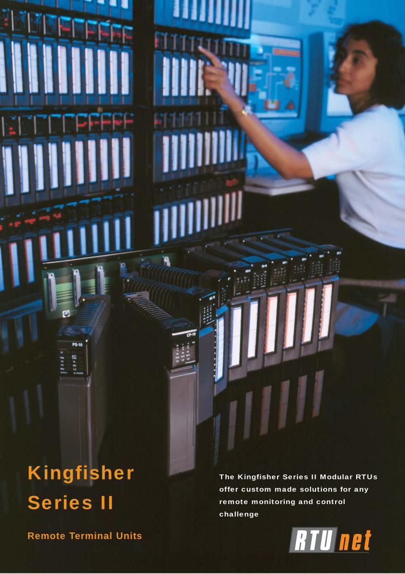
KingfisherSeries IIRemote Terminal Units
The Kingfisher Series II Modular RTUs
offer custom made solutions for any
remote monitoring and control
challenge
Creating an RTU Solution
Contact your local RTU-netrepresentative:
RTU-net (International) Ltd.,
www.rtu-net.comEmail: [email protected]
Kingf isher Series I IRTUs
Information subject to change without notice.© Copyright 2003 RTU-net Ltd.All rights reserved. Issue 05/03.
PS-11 CP-11 I/O & COMMS MODULES AS REQUIRED
RS232-1
OPTION
OPTION
Mains Input (90-260 VAC)
Aux. 24V Output (Optional)
12V Battery Output / Input
Aux. 12V Output
Earth
PS-11 CP-11
RS232-1
OPTION
OPTION
Optional redundant Power Supplies and / or Processor Modules
12 Slot Backplane
PS-11 CP-11 I/O & COMMS
Modules as Required
RS232-1
OPTION
OPTION
Mains Input (90-260 VAC)
Aux. 24V Output (Optional)
12V Battery Output / Input
Aux. 12V Output
Earth
6 Slot Backplane
PC-1 I/O & COMMSI/O & COMMS
Modules as Req'd
12V Battery Output / Input
Aux. 12V Output
Earth
RS232-1
Option
AC / DCPOWER SUPPLY
Typically 3A
Mains Input
12V DC Input
Aux. 24V Output (Optional)
4 Slot Backplane
1. Determine the number of inputs and outputs required. Select any combination of I/O modules to provide the necessary inputs and outputs. Selecting the minimum amount of I/O modules will minimise the cost of the RTU.
2. Choose the communications media (eg radio).
3. Determine the number and type of communication ports required. A PC-1 has one RS232 port andone option port. A CP-11/21 or an MC-11 has one RS232 port and two option ports.
4. Choose a Power Supply/Processor solution. EveryRTU must have one processor module and at least one power supply. - The PC-1 is a combined Power Supply/Processor
Module and requires an external AC/DC power supply- A seperate Power Supply Module (PS-11 or PS-21) is
used in conjunction with a Processor Module (CP-11 or CP-21).
Notes: The PC-1 module is a simpler processor and does not have the same speed, memory and functionality of aCP-x processor. A PC-1 is only used on a four slot backplane.
5. According to the number of modules required, selectone or more backplanes. Typical RTU layouts are shown below. Multiple backplanes can be linked together. Only one processor is required for the whole RTU, while one PS-x power supply is requiredfor each backplane in the RTU to provide the necessary I/O power.
6. Consider physical and environmental factors when choosing enclosures as well as other needs such as surge protection.
7. Decide on a communication strategy to determine how and when the RTUs will communicate and which RTU(s) will initiate data transfers.
8. Outline the RTU configuration requirements. Configure the RTU using TOOLKIT software.

powerful
expandable
The Kingfisher Series II Remote Terminal Unit design allows the user to create customsolutions by plugging a wide range of modules onto a backplane. This flexibility allowsRTUs to be constructed to meet the exact needs of each site.
Each RTU can have as few as four I/O and one communication port, to thousands of I/Oand sixteen communication ports.
Once your requirements are established, simply customise a Kingfisher Series II RTU tomeet your needs. Should your requirements grow in the future, just upgrade yourexisting RTU by plugging in new modules or downloading new firmware.
Now that’s true flexibility and future proofing!
Flexibility to create the perfect RTU solution
Kingfisher Series II individual modules can be assembled in almost any configuration toachieve the best solution. • 4 to >1000 I/O• 1 to 16 communication ports• Backplanes may be daisy chained to expand I/O and communication ports capacity• Multi I/O modules combine analog and digital I/Os (eg. 2xAI, 8xDI, 2xDO) in one module.
Easy upgrade path
The modular design of Kingfisher Series II RTUs allows its capacity to be expanded by pluggingin new modules and its capabilities increased by downloading new firmware and software.
Connects to a range of communication equipment
The Kingfisher Series II RTUs can connect to a wide range of media that include:• dedicated radio• packet radio• satellite• PSTN dial-up• cellular (voice grade and dedicated data)• two-wire and four-wire leased lines• ISDN• RS232/RS485/RS422• Ethernet• fibre optic
Kingfisher Series II RTUs can also initiate alphanumericmessages to pager receivers and mobile phones (SMS).
Processing power
Powerful Intel 32 bit processors, largememory capacity and a real-time operatingsystem provide the power for quick logicprocessing, communications and data storage.Kingfisher Series II RTUs provide control capabilitiesthat were previously only available in PLCs.
flexible
Features of Kingfisher Series II RTUs
Compatible with many devices and networks
Kingfisher Series II RTUs communicate using a wide range of protocolsthat provide connection to local devices such as PLCs, flow computers,shaft encoders, smart transducers, circuit breakers and pager radios.Connection to communication networks is also provided, includingsupport of the Hayes AT command set, DNP3 protocol, MODBUSprotocol, TCP/IP and emulation of other RTU and PLC manufacturers’protocols.
Easy configuration
TOOLBOX, a Microsoft Windows based RTU configuration anddiagnostic program offers on-line help, configuration examples, anddrag and drop capabilities. TOOLKIT features IEC 61131-3 compliant
editing and allows you to configure RTUs remotely or locally, on-line or off-line, and from RTU to RTU, or PC to RTU.
Control is implemented using ladder logic which is compiled and downloaded into the RTU.
The use of databases for definition of I/O and system variables allows the importing and exportingof configuration data to and from other SCADA system databases.
Advanced power management features
Power consumption can be reduced by up to 90%. Kingfisher Series II RTUs can shut down fieldpower between scans and maintain a low power idle state until woken by an event.
RTU self-configuration
The Series II RTU auto-detects the presence of modules plugged in the backplane(s), and willgenerate alarms if a module fails or is inserted in the wrong location.Modules can be ‘hot swapped’ or added while the RTU is running.
Plug it in and GO!
Kingfisher Series II RTUs are designed to plug in and go to work for you with a minimum of fuss.Our systems engineering experts can also assist with a packaged or boxed solution which iscustomised to your particular site, application and communication requirements.
Industries
water wastewater power mining oil gas
broadcasting transportation irrigation management
chemical telecommunications emergency services
construction substation monitoring
Series II RTUs can be customised to suit
any industry
Kingf isher Series I IRTUs

General Specifications
Inputs & OutputsMaximum I/O 1024Racks up to 4Total Modules up to 64I/O Per Rack up to 256I/O Configuration Automatic/ManualSlots Per Rack/Backplane 4 / 6 / 12Removable Connectors YesDigital Modules max. of 16 inputs or 16
outputs / moduleAnalog Modules max. of 16 inputs or 16
outputs / module
Processor UnitType 80C188 / 80C386Flash RAM 128 to 1024 kBytesRAM 128 to 2048 kBytesReal Time Clock YesBattery Backup RAM / RTCSerial Ports 1 (optional up to 3)RTU Address 1 to 255Radio Interface YesPrivate Line Interface YesPSTN (Dial-up / Answer) Yes
Scan RateDigital 0.5 mS / moduleAnalog 1.5 mS / modulePID 4 / second
Communications SupportedTotal Ports / RTU 16Line Modem Standards V22, V22BIS, V23, V32, V34Radio Modem Standards V23, MSK, GMSK, BELL 202Serial Standards RS 232 / 485 / 422Master / Slave YesPeer-to-Peer YesFall Back Levels YesPC Link YesProtocol Kingfisher, MODBUS, DNP3
Allen Bradley and many moreProtocol Emulation Yes
ConfigurationAuto YesLocal (Portable PC) YesNetwork Yes
Configuration TypesAnalog Value Test YesPID Control YesLadder Logic Yes
DiagnosticsPre-Programmed YesI/O Modules LEDsCPU Modules LEDsPower Supply Modules LEDsReport Via Network YesSoftware Yes
DebugLocal Watch Dog Timer YesCommunication Status YesConfiguration Display YesI/O Status YesDebug Yes
PowerAC Supply 90 to 260 VDC Supply 20 to 60 VSolar Supply 12 V DCPower Down Modes YesBattery Backup YesBattery Size VariousBattery Charging Option Yes
EnvironmentalAmbient Temperature -20oC to 70oCStorage Temperature -40oC to 85oCHumidity 5% to 98% non-condensingDielectric Strength 3000 V, 1 minNoise Immunity IEEE 472
Redundancy LevelsCPUs / RTU 2Power Supplies / Rack 2
Kingf isher Series I IRTUs
Information subject to change without notice.© Copyright 2003 RTUnet (Aust) Pty Ltd.
All rights reserved. Issue 07/03.

Modules for the Series II RTU
Kingf isher Series I IRTUs
I/O ModulesAI-10 High Performance Analog Input
8 channel (differential). Voltage Ranges: ±10V, ±5V or ±2.5VCurrent Ranges: ±40mA, ±20mA or ±10mAResolution: 16 bitAccuracy: 0.1%, 0-500CScan Rate: >100 reading per second
AO-2 Analog Current Output4 channel analog outputOutput Range: 4 to 20mA and 0 to 20mASupply Voltage: +5V and 24VDC backplaneResolution: 12 bit
DI-5 Digital Input - Dry Contact16 channel digital inputInput Voltage: 10 to 28V DCContact Current: 4mA (typical)Pulse Totalisation: (DI 1 to 4) 0-65535 pulsesPulse Rates: 255Hz or 10kHz (channels 1-4)
DI-10 Intelligent Digital Input - AC or DC16 channel digital input (pulse and SoE)Input Voltage: 6 to 130V DC, 20 to 260V ACContact Current: 4mA (typical)Pulse Totalisation: 0-65525 pulsesPulse Rates: 1kHz or 10kHz
DO-1 Isolated Relay Output, NO/NC8 channel digital outputRated Voltage: 24 / 48V DC, 120 / 240V ACMax. Load: 4A per output (20A max. per module)
DO-2 Relay Output, NO16 channel open collector outputsRated Voltage: 24V DC, 120 / 240V ACMax. Load: 2A per output (8A max. per common)
DO-5 Relay Driver Output16 channel relay driver ouptutOptional: External 16 point Double Pole Double Throw (DPDT) relay board (TEL/REL/001)
Mixed I/O ModulesIO-2 Combined Digital I/O Module
8 x DI + 8 x DOIO-3 Combined Analog / Digital I/O Module
4 x AI + 1 x AO + 4 DI + 4 x DOIO-4 Combined Analog /Digital I/O Module
2 x AI + 8 x DI + 2 x DOIO-2 / 3 / 4 Specifications:
Analog Inputs (IO-3 & 4 only):Voltage Ranges: 1 to 5V DCCurrent Ranges: 4 to 20mA and 0 to 20mAResolution: 12 bitAccuracy: 0.1%, 0-500CScan Rate: 2 mSec
Digital Inputs:Input Voltage: 0 to 30V AC/DCContact Current: 4mA (typical)
Digital Outputs:Rated Voltage: 24V DC, 120 / 240V ACMax. Load: 2A per output (8A max. per common)
Power Supply ModulesPS-11 AC Supply upply Input Module 90 to 260V ACPS-21 DC Supply Input Module 20 to 60V DCPS-11 / 21 Specifications:
Outputs: +5V, +12V, +24V (opt.), battery charging Total 70W max.Isolation: 3KV AC input / DC outputLED indicators: DC supply , Bat., Aux. converterConnectors: Removable AC/DC connectors
Processor & Communication ModulesCP-11 Processor Module - Low memory
1MB RAM,1 x RS232, 2 x option portsCP-21 Processor Module - High memory
2MB RAM, TCP/IP support, 1 x RS232, 2 x option ports
MC-11 Multi Communications ModuleAdditional ports, 1 x RS232, 2 x option ports
Communications Option Boards(for ports 2 & 3 of CP-11, CP-21, MC-11 modules)
‘S’ RS232 port‘I’ Isolated RS232 / 422 / 485 port‘D’ PSTN, V.34 33.6kbps dial up port‘L’ 2/4 wire V.23 FSK port‘H’ HART interface port‘F’ Fibre optic port‘E’ Ethernet port (port 2 of CP-21 only)‘V’ 2 channel video capture port
BackplanesBA-40 4 slot backplaneBA-6 6 slot backplaneBA-12 12 slot backplane (19” rack mountable)
Information subject to change without notice.© Copyright 2003 RTUnet (Aust) Pty Ltd.
All rights reserved. Issue 07/03.

KingfisherSeries IIRemote Terminal Units
The Kingfisher Series II Modular RTUs
offer custom made solutions for any
remote monitoring and control
challenge
Creating an RTU Solution
Kingf isher Series I IRTUs
Information subject to change without notice.© Copyright 2003 RTUnet (Aust) Pty Ltd.
All rights reserved. Issue 07/03.
PS-11 CP-11 I/O & COMMS MODULES AS REQUIRED
RS232-1
OPTION
OPTION
Mains Input (90-260 VAC)
Aux. 24V Output (Optional)
12V Battery Output / Input
Aux. 12V Output
Earth
PS-11 CP-11
RS232-1
OPTION
OPTION
Optional redundant Power Supplies and / or Processor Modules
12 Slot Backplane
PS-11 CP-11 I/O & COMMS
Modules as Required
RS232-1
OPTION
OPTION
Mains Input (90-260 VAC)
Aux. 24V Output (Optional)
12V Battery Output / Input
Aux. 12V Output
Earth
6 Slot Backplane
PC-1 I/O & COMMSI/O & COMMS
Modules as Req'd
12V Battery Output / Input
Aux. 12V Output
Earth
RS232-1
Option
AC / DCPOWER SUPPLY
Typically 3A
Mains Input
12V DC Input
Aux. 24V Output (Optional)
4 Slot Backplane
1. Determine the number of inputs and outputs required. Select any combination of I/O modules to provide the necessary inputs and outputs. Selecting the minimum amount of I/O modules will minimise the cost of the RTU.
2. Choose the communications media (eg radio).
3. Determine the number and type of communication ports required. A PC-1 has one RS232 port andone option port. A CP-11/21 or an MC-11 has one RS232 port and two option ports.
4. Choose a Power Supply/Processor solution. EveryRTU must have one processor module and at least one power supply. - The PC-1 is a combined Power Supply/Processor
Module and requires an external AC/DC power supply- A seperate Power Supply Module (PS-11 or PS-21) is
used in conjunction with a Processor Module (CP-11 or CP-21).
Notes: The PC-1 module is a simpler processor and does not have the same speed, memory and functionality of aCP-x processor. A PC-1 is only used on a four slot backplane.
5. According to the number of modules required, selectone or more backplanes. Typical RTU layouts are shown below. Multiple backplanes can be linked together. Only one processor is required for the whole RTU, while one PS-x power supply is requiredfor each backplane in the RTU to provide the necessary I/O power.
6. Consider physical and environmental factors when choosing enclosures as well as other needs such as surge protection.
7. Decide on a communication strategy to determine how and when the RTUs will communicate and which RTU(s) will initiate data transfers.
8. Outline the RTU configuration requirements. Configure the RTU using TOOLKIT software.