series mrk and mrm - schroedahl · series mrk and mrm the ultimate high ... bypass line to prevent...
TRANSCRIPT

Series MRK and MRMFor nominal pressures up to 640 bar /class 4500
Automatic Recirculation Valve for pump protection
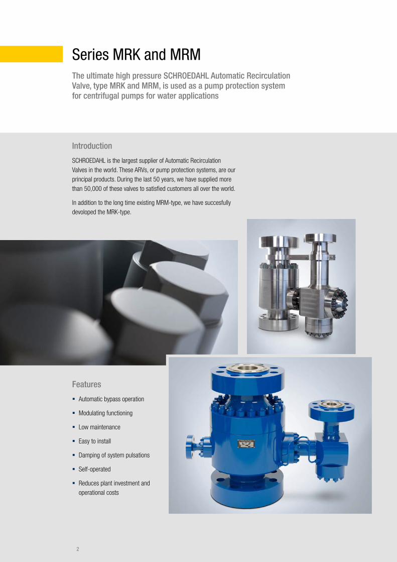
Series MRK and MRMThe ultimate high pressure SCHROEDAHL Automatic Recirculation Valve, type MRK and MRM, is used as a pump protection system for centrifugal pumps for water applications
Features
� Automatic bypass operation
� Modulating functioning
� Low maintenance
� Easy to install
� Damping of system pulsations
� Self-operated
� Reduces plant investment and operational costs
Introduction
SCHROEDAHL is the largest supplier of Automatic Recirculation Valves in the world. These ARVs, or pump protection systems, are our principal products. During the last 50 years, we have supplied more than 50,000 of these valves to satisfied customers all over the world.
In addition to the long time existing MRM-type, we have succesfully devoloped the MRK-type.
2

Function MRM
The check valve (item. 7, page 4) moves upwards with an increase in main flow and downwards with a decrease in flow. The movement of the check valve is transmitted directly via the lever (item. 13, page 4) to the bypass system. When the check valve is closed, the bypass is completely open and full bypass flow is allowed to the deaerator (suction tank).
Function MRK
The MRK valve system is compromised of a check valve and a special control and throttle device for the minimum flow recirculation system (bypass system). The general valve functioning is related to the process flow quantity (flow sensitive). The bypass system itself consists of a primary regulating device (multi-staged), which is controlled by the main check valve and also a secondary extra special multi-staged pressure regulator. The functioning of the complete bypass is therefore split into two parts. Both parts (primary and secondary part) have to work together to fulfil the required pressure drop function as declared in our data sheet. The secondary part is controlled via the outer-connected pressure piping on the bypass section
With increasing main flow, the check valve is lifted off its seat and moves upwards. Only when the bypass is completely closed, full flow to the system is allowed. The valve is set in the factory in such a way that the specified minimum flow is reached when the check valve is seated (this means that the main flow is zero).
The valve protects high pressure centrifugal pumps against overheating and cavitation problems by automatically maintaining a minimum flow when the system flow is at low load condition. At lower process flows, the check valve activates the bypass trim parts via a lever system, so that the pump is protected with the correct minimum flow. When the process/system flow starts (increases), the main check valve lifts off its seat and starts to operate (modulate) the bypass recirculation flow that returns to the system tank. When the check valve identifies enough system flow, the bypass closes automatically (switch point). If the system flow decreases again, then the bypass also starts to recirculate automatically.
3

Typical drawing: Automatic Recirculation Valve MRK and MRM
Design and number of stages depends on load conditions.
P = Pump end
R = Pipeline end
B = Bypass end
Fig. 1: Valve type MRM
Fig. 2: Valve type MRK
01
02
04
04
26
28
45
44
06
08
41
07.1
07.2
03.1
30
13 14 11 16 15 21 31
322729
3434.1 25
3535.1
3333.1
12 10 36 23
25.129.1
27.1
50
393737.1
3838.1
11.1
21
32.1
12.1
10.1
23.1
36.1
9.2
4748
9.109
07
B = Bypass end
R = Pipeline end
P = Pump end
B
R
P
P = Pump end
R = Pipeline end
B = Bypass end
4

MRM standard parts listItem Description01 02 03 03.1 04 06 07 07.1 07.2 08 09 09.1 09.2 10 10.1 11 12 12.1 13 14
Lower Body Upper Body Stem Guide Stem Guide Guide Bolt Spring Check Valve Cpl. Check Valve Stem Liner Bypass Housing Cpl. Flange Bypass Vortex Bushing Orifice Plate Plunger Vortex Plug Pin Lever Pin
MRM standard parts listItem Description15 16 20 21 22 23 23.1 23.2 24 24.1 25 26 27 28 29 30 31 31.1 32 33
Roller Link Nut Cotter Spring Gland O-Ring Step Seal Glyd Ring O-Ring Guide Ring Guide Ring Stud Bolt Stud Bolt Packing Bushing Packing Bushing Flange O-Ring O-Ring Support Ring Guide Ring Packing Ring
MRM standard parts listItem Description34 34.1 35 36 37 38 39 40 41 42 43 44 45 46 47 47.1 47.2 48 49 54
O-Ring Support Ring Guide Ring Cover Bushing O-Ring Stud Bolt Hexagon Nut Hexagon Nut Hexagon Nut Guide Ring Pin Ball Guide Ring O-Ring Step Seal Glyd Ring Guide Ring Guide Ring O-Ring
Valve sizes
The MRK and MRM type valves are available in sizes from DN 80 (3”) to DN 300 (12”). Special sizes are available on request.
Connections
Flanges in accordance with EN or ASME; flanges in accordance with other standards (ISO, BS, JIS, NF) or hub connections upon request. The valve in- and outlet can also be supplied with welding ends.
Materials
Standard housing materials available:
� Carbon steel ASTM A105, EN 1.0460
� Stainless steel ASTM A182, F316L, EN 1.4404 or ASTM A182 F347, EN 1.4550
� Duplex steel ASTM A479 (F51), EN 1.4462 or ASTM A479 (F55), EN 1.4501, plus materials for NORSOK applications.
The standard internals are made of stainless steel with a minimum chrome content of 13% (not valid for duplex housing material).
Other materials for housing and internals upon request.
Selection of the seal material according to medium and temperature conditions.
Selection of the housing material according to design pressure, design temperature and medium.
Parts list (example for MRM type)
5

Operation range definition for MRK and MRM
The following descriptions typically classify the pump protection application:
Standard Operation Range Application, which is more typical for lower pressure applications rather than the high pressure MRK and MRM type applications: The pump protection valves usually operate in the load range from 40% to 100% of the rated process flow. The automatic valve handles the typical time limited start-up and shut-down phase by automatically modulating the bypass control operation. MRK/MRM valves for high pressure services typically also need an adequately high bypass back pressure, e.g. an orifice restriction in the bypass line to prevent cavitation during the bypass flow phase.
MRK and MRM valves should follow the following classification:
Full Operation Range Application, which is typical for MRK/MRM applications: For high pressure MRK (also for MRM) applications with the explicit definition of the full load range from 0 % to 100 % process flow, it is mandatory before order placement to evaluate special design impacts on the valve. Otherwise, the application will be classified as a standard range type. For the high load range, depending on the existing bypass pressure level, it may be necessary to increase the bypass back pressure to prevent cavitation, also in the low load range where the bypass is in modulating action. Therefore, the installation of a special back pressure valve BPV is recommended for the full operation range application to ensure that the bypass pressure level is always at a suitable level.
6

7

Size code Pressure class code Connection code Configuration code
DN 80 (3") = 10
DN 100 (4") = 11
DN 125 (5") = 12
DN 150 (6") = 13
DN 200 (8") = 15
DN 250 (10") = 16
DN 300 (12") = 17
PN 63 Class 300 = 5
PN 100 Class 600 = 6
PN 160 Class 900 = 7
PN 250 Class 1500 = 8
PN 320 = 9
PN 400 Class 2500 = 0
PN 500 Class 3200 = A
PN 640 Class 4500 = B
F = EN Flanges
U = ASME Flanges
S = Welding Ends
V = Vertical Installation
H = Horizontal Installation
A = Manual Start-up
W = Oversized Bypass or
Start-up Connection
CS = Carbon Steel Body
SS = Stainless Steel Body
SD = Duplex Steel Body
Example of type description for MRK and MRM valves
MRM150UVW-CS: valve type MRM, 8", Class 2500, ASME flanges, vertical installation, carbon steel housing material, oversized bypass connection
Type description
8

Bypass lineTo System
ARV
Place for BPV orOrifice
Tank
Straight pipe run 5x NPS
1.) Best Distance: Zero!2.) maximum 5m with straight pipe run of: 2 x DN (no elbow)
P
R
B
Pump
Installation information
The Automatic Recirculation Valve should be installed as close as possible to the centrifugal pump discharge, preferably directly on the outlet of the pump.
To prevent low frequency shocks caused by pulsation of the medium, the distance between pump outlet and valve inlet should not exceed 5 m with a straight pipe run at the inlet. Exceptions have to be communicated to SCHROEDAHL.
Vertical installation is preferred, but horizontal installation is also possible upon request. MRK and MRM valves operate at a low noise level and ensure a high reliability due to their sturdy design.
The recommended filter at the pump inlet should have a maximum mesh size of 0.3 to 0.5 mm. During commissioning we recommend a smaller filter mesh size (e.g. 0.1 mm).
Maintenance, spares and testing
Maintenance instructions are available upon request or at www.schroedahl.com.
Typically we recommend an inspection after commissioning (a gasket set is then required); after two years of operation, we recommend a bypass set for your stock.
A complete valve performance test run is recommended to be done together with the original pump. The bypass Kv/Cv value test can be certified at our test facility. Please contact SCHROEDAHL for additional information.
9
Customer:
Enquiry no.:
Prior reference:
Order no.:
Project:
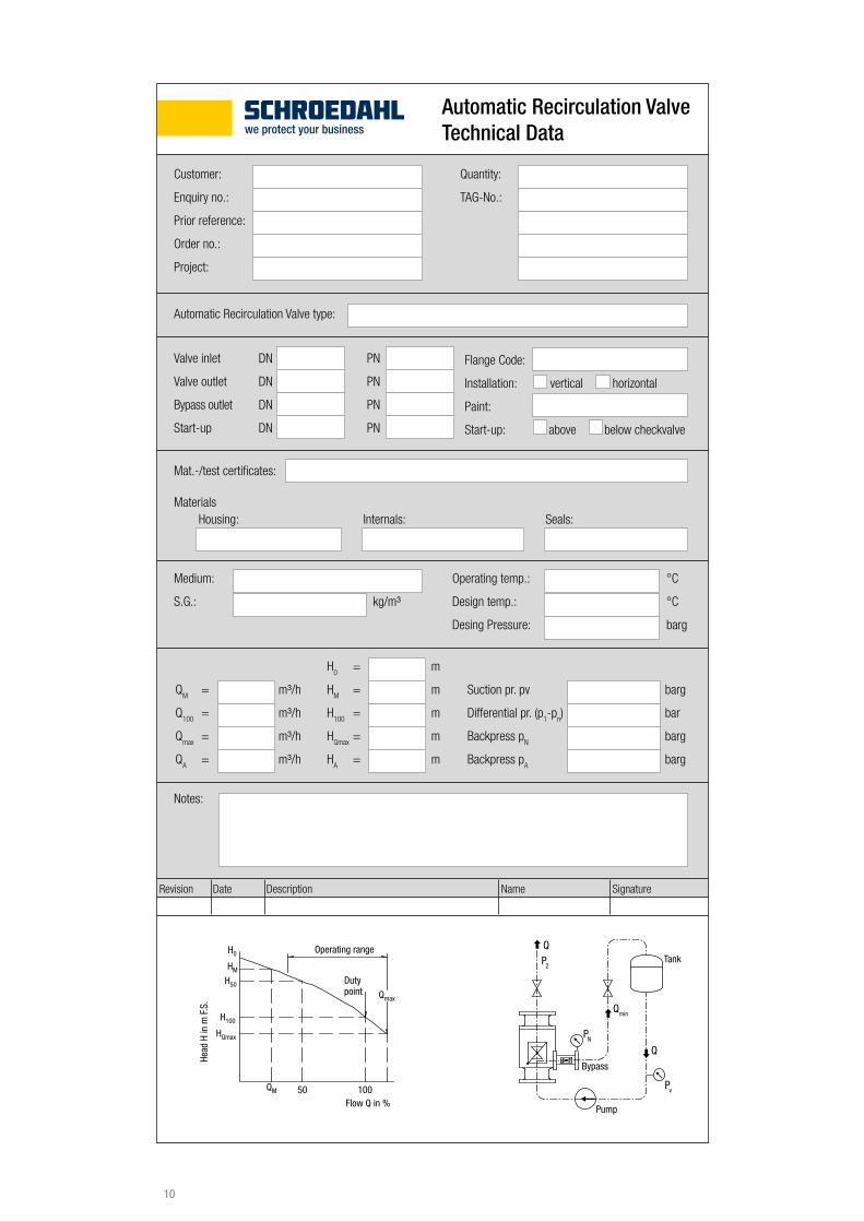
Automatic Recirculation Valve Technical Data
Quantity:
TAG-No.:
Automatic Recirculation Valve type:
Mat.-/test certificates:
MaterialsInternals: Seals:
Medium:
S.G.: kg/m³
Operating temp.: °C
Design temp.: °C
Desing Pressure: barg
QM = m³/h
Q100
= m³/h
Qmax
= m³/h
QA = m³/h
H0 = m
HM = m
H100
= m
HQmax
= m
HA = m
Suction pr. pv barg
Differential pr. (p1-p
n) bar
Backpress pN barg
Backpress pA barg
Notes:
Flange Code:
Installation: vertical horizontal
Paint:
Start-up: above below checkvalve
Revision Date Description Name Signature
Valve inlet DN PN
Valve outlet DN PN
Bypass outlet DN PN
Start-up DN PN
Pv
Qmin
Q
P2
Q
Pump
Tank
Duty point
Operating range
Flow Q in %
H0
HM
H50
H100
Qmax
QM 50 100
HQmax
Head
H in
m F
.S.
PN
Bypass
Housing:
10


©20
16 X
YQOM
Gm
bH · w
ww.xy
qom
.net /
rev.
2016
_UK_
005
SCHROEDAHL GmbH Alte Schönenbacher Str. 4 51580 Reichshof-Mittelagger GERMANY
Phone +49 2265 9927-0 Fax +49 2265 9927-927
www.schroedahl.com [email protected]