series-parallel ac networks · copyright ©2011 by pearson education, inc. publishing as pearson...
TRANSCRIPT

Copyright ©2011 by Pearson Education, Inc.
publishing as Pearson [imprint] Introductory Circuit Analysis, 12/e
Boylestad
Chapter 16
Series-Parallel ac
Networks

Introductory Circuit Analysis, 12/e
Boylestad
Copyright ©2011 by Pearson Education, Inc.
publishing as Pearson [imprint]
OBJECTIVES
• Develop confidence in the analysis of seriesparallel ac networks.
• Become proficient in the use of calculators and computer methods to support the analysis of ac series-parallel networks.
• Understand the importance of proper grounding in the operation of any electrical system.

Introductory Circuit Analysis, 12/e
Boylestad
Copyright ©2011 by Pearson Education, Inc.
publishing as Pearson [imprint]
INTRODUCTION
• In general, when working with series-parallel ac networks, consider the following approach: – Redraw the network, using block
impedances to combine obvious series and parallel elements, which will reduce the network to one that clearly reveals the fundamental structure of the system.
– Study the problem and make a brief mental sketch of the overall approach you plan to use. Doing this may result in time- and energy-saving shortcuts.

Introductory Circuit Analysis, 12/e
Boylestad
Copyright ©2011 by Pearson Education, Inc.
publishing as Pearson [imprint]
INTRODUCTION
– After the overall approach has been determined, it is usually best to consider each branch involved in your method independently before tying them together in seriesparallel combinations..
– When you have arrived at a solution, check to see that it is reasonable by considering the magnitudes of the energy source and the elements in the circuit.

Introductory Circuit Analysis, 12/e
Boylestad
Copyright ©2011 by Pearson Education, Inc.
publishing as Pearson [imprint]
ILLUSTRATIVE EXAMPLES
FIG. 16.1 Example 16.1.

Introductory Circuit Analysis, 12/e
Boylestad
Copyright ©2011 by Pearson Education, Inc.
publishing as Pearson [imprint]
ILLUSTRATIVE EXAMPLES
FIG. 16.2 Network in Fig. 16.1 after assigning
the block impedances.

Introductory Circuit Analysis, 12/e
Boylestad
Copyright ©2011 by Pearson Education, Inc.
publishing as Pearson [imprint]
ILLUSTRATIVE EXAMPLES
FIG. 16.3 Example 16.2. FIG. 16.4 Network in Fig. 16.3
after assigning the block
impedances.

Introductory Circuit Analysis, 12/e
Boylestad
Copyright ©2011 by Pearson Education, Inc.
publishing as Pearson [imprint]
ILLUSTRATIVE EXAMPLES
FIG. 16.5 Example 16.3.
FIG. 16.6 Network in Fig. 16.5 after
assigning the block
impedances.

Introductory Circuit Analysis, 12/e
Boylestad
Copyright ©2011 by Pearson Education, Inc.
publishing as Pearson [imprint]
ILLUSTRATIVE EXAMPLES
FIG. 16.7 Example 16.4. FIG. 16.8 Network in Fig. 16.7 after
assigning the block
impedances.

Introductory Circuit Analysis, 12/e
Boylestad
Copyright ©2011 by Pearson Education, Inc.
publishing as Pearson [imprint]
ILLUSTRATIVE EXAMPLES
FIG. 16.9 Determining the voltage Vab
for the network in Fig. 16.7.
FIG. 16.10 Basic transistor
amplifier.

Introductory Circuit Analysis, 12/e
Boylestad
Copyright ©2011 by Pearson Education, Inc.
publishing as Pearson [imprint]
ILLUSTRATIVE EXAMPLES
FIG. 16.11 Network in Fig. 16.10 following the
assignment of the block impedances.
Introductory Circuit Analysis, 12/e
Boylestad
Copyright ©2011 by Pearson Education, Inc.
publishing as Pearson [imprint]
ILLUSTRATIVE EXAMPLES
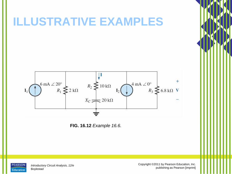
FIG. 16.12 Example 16.6.

Introductory Circuit Analysis, 12/e
Boylestad
Copyright ©2011 by Pearson Education, Inc.
publishing as Pearson [imprint]
ILLUSTRATIVE EXAMPLES
FIG. 16.13 Network in Fig. 16.12 following
the assignment of the subscripted
impedances.

Introductory Circuit Analysis, 12/e
Boylestad
Copyright ©2011 by Pearson Education, Inc.
publishing as Pearson [imprint]
ILLUSTRATIVE EXAMPLES
FIG. 16.14 Example 16.7.

Introductory Circuit Analysis, 12/e
Boylestad
Copyright ©2011 by Pearson Education, Inc.
publishing as Pearson [imprint]
ILLUSTRATIVE EXAMPLES
FIG. 16.15 Network in Fig. 16.14 following the assignment of the
subscripted impedances.

Introductory Circuit Analysis, 12/e
Boylestad
Copyright ©2011 by Pearson Education, Inc.
publishing as Pearson [imprint]
ILLUSTRATIVE EXAMPLES
FIG. 16.16 Finding the total admittance for the network in Fig. 16.14 using the TI-89
calculator.

Introductory Circuit Analysis, 12/e
Boylestad
Copyright ©2011 by Pearson Education, Inc.
publishing as Pearson [imprint]
ILLUSTRATIVE EXAMPLES
FIG. 16.17 Converting the rectangular form in Fig. 16.16 to polar form.

Introductory Circuit Analysis, 12/e
Boylestad
Copyright ©2011 by Pearson Education, Inc.
publishing as Pearson [imprint]
ILLUSTRATIVE EXAMPLES
FIG. 16.18 Example 16.8.

Introductory Circuit Analysis, 12/e
Boylestad
Copyright ©2011 by Pearson Education, Inc.
publishing as Pearson [imprint]
ILLUSTRATIVE EXAMPLES
FIG. 16.19 Network in Fig. 16.18 following the assignment of
the subscripted impedances.

Introductory Circuit Analysis, 12/e
Boylestad
Copyright ©2011 by Pearson Education, Inc.
publishing as Pearson [imprint]
ILLUSTRATIVE EXAMPLES
FIG. 16.20 Finding the total impedance for the network in Fig. 16.18 using the TI-89
calculator.

Introductory Circuit Analysis, 12/e
Boylestad
Copyright ©2011 by Pearson Education, Inc.
publishing as Pearson [imprint]
LADDER NETWORKS
FIG. 16.21 Ladder network.
Introductory Circuit Analysis, 12/e
Boylestad
Copyright ©2011 by Pearson Education, Inc.
publishing as Pearson [imprint]
LADDER NETWORKS
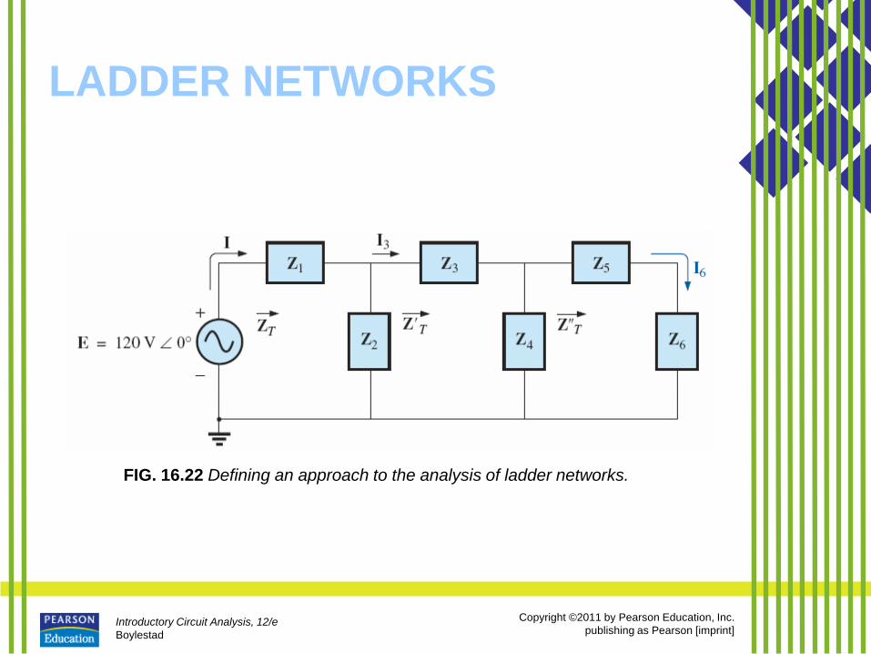
FIG. 16.22 Defining an approach to the analysis of ladder networks.

Introductory Circuit Analysis, 12/e
Boylestad
Copyright ©2011 by Pearson Education, Inc.
publishing as Pearson [imprint]
GROUNDING
• Ground potential is zero volts at every
point in a network that has a ground
symbol.
– An earth ground is one that is connected
directly to the earth by a low-impedance
connection.
– A second type is referred to as a chassis
ground, which may be floating or
connected directly to an earth ground.

Introductory Circuit Analysis, 12/e
Boylestad
Copyright ©2011 by Pearson Education, Inc.
publishing as Pearson [imprint]
GROUNDING
FIG. 16.23 Demonstrating the effect of the oscilloscope ground on the measurement of
the voltage across resistor R1.

Introductory Circuit Analysis, 12/e
Boylestad
Copyright ©2011 by Pearson Education, Inc.
publishing as Pearson [imprint]
GROUNDING
FIG. 16.24 Three-wire conductors: (a) extension cord; (b) home outlet.
Introductory Circuit Analysis, 12/e
Boylestad
Copyright ©2011 by Pearson Education, Inc.
publishing as Pearson [imprint]
GROUNDING
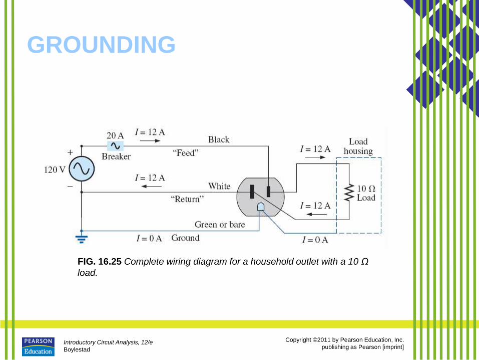
FIG. 16.25 Complete wiring diagram for a household outlet with a 10 Ω
load.

Introductory Circuit Analysis, 12/e
Boylestad
Copyright ©2011 by Pearson Education, Inc.
publishing as Pearson [imprint]
GROUNDING
FIG. 16.26 Demonstrating the importance of a properly grounded appliance:
(a) ungrounded; (b) ungrounded and undesirable contact; (c) grounded
appliance with undesirable contact.

Introductory Circuit Analysis, 12/e
Boylestad
Copyright ©2011 by Pearson Education, Inc.
publishing as Pearson [imprint]
APPLICATIONS
• The vast majority of the applications appearing throughout the text have been of the series-parallel variety.
• The following are series-parallel combinations of elements and systems used to perform important everyday tasks.
• The ground fault circuit interrupter outlet employs series protective switches and sensing coils and a parallel control system, while the ideal equivalent circuit for the coax cable employs a series-parallel combination of inductors and capacitors.

Introductory Circuit Analysis, 12/e
Boylestad
Copyright ©2011 by Pearson Education, Inc.
publishing as Pearson [imprint]
GFCI (Ground Fault Circuit
Interrupter)
FIG. 16.27 GFCI outlet: (a) wall-
mounted appearance; (b) basic
operation; (c) schematic.
Introductory Circuit Analysis, 12/e
Boylestad
Copyright ©2011 by Pearson Education, Inc.
publishing as Pearson [imprint]
GFCI (Ground Fault Circuit
Interrupter)
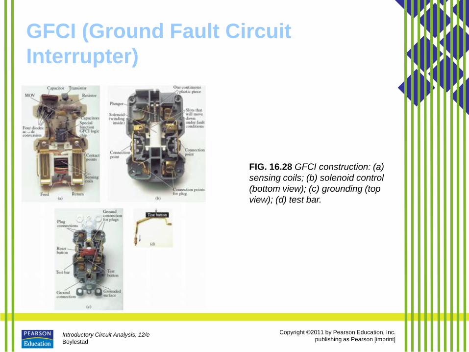
FIG. 16.28 GFCI construction: (a)
sensing coils; (b) solenoid control
(bottom view); (c) grounding (top
view); (d) test bar.

Introductory Circuit Analysis, 12/e
Boylestad
Copyright ©2011 by Pearson Education, Inc.
publishing as Pearson [imprint]
COMPUTER ANALYSIS PSpice
FIG. 16.29 Determining the voltage across R1 and R2 using the VPRINT
option of a PSpice analysis.
Introductory Circuit Analysis, 12/e
Boylestad
Copyright ©2011 by Pearson Education, Inc.
publishing as Pearson [imprint]
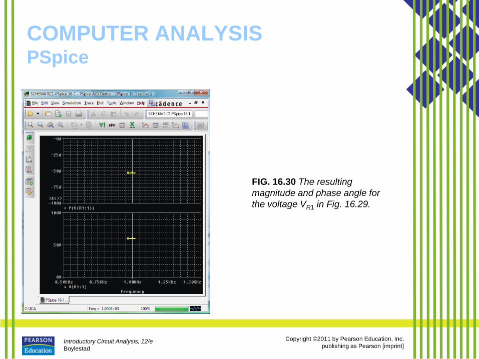
COMPUTER ANALYSIS PSpice
FIG. 16.30 The resulting
magnitude and phase angle for
the voltage VR1 in Fig. 16.29.

Introductory Circuit Analysis, 12/e
Boylestad
Copyright ©2011 by Pearson Education, Inc.
publishing as Pearson [imprint]
COMPUTER ANALYSIS PSpice
FIG. 16.31 The VPRINT1 (Vr1) and VPRINT2 1VR2 response for the network in Fig.
16.29.

Introductory Circuit Analysis, 12/e
Boylestad
Copyright ©2011 by Pearson Education, Inc.
publishing as Pearson [imprint]
COMPUTER ANALYSIS PSpice
FIG. 16.32 The PSpice
response for the voltage
between the two points above
resistors R1 and R2.
Introductory Circuit Analysis, 12/e
Boylestad
Copyright ©2011 by Pearson Education, Inc.
publishing as Pearson [imprint]
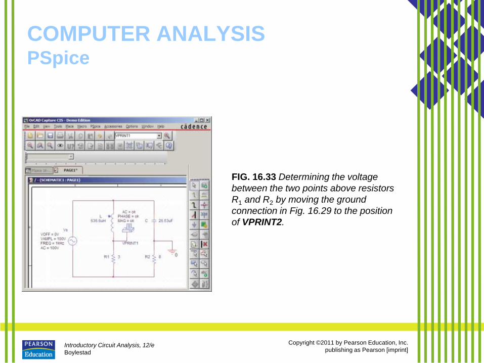
COMPUTER ANALYSIS PSpice
FIG. 16.33 Determining the voltage
between the two points above resistors
R1 and R2 by moving the ground
connection in Fig. 16.29 to the position
of VPRINT2.

Introductory Circuit Analysis, 12/e
Boylestad
Copyright ©2011 by Pearson Education, Inc.
publishing as Pearson [imprint]
COMPUTER ANALYSIS PSpice
FIG. 16.34 PSpice response
to the simulation of the
network in Fig. 16.33.

Introductory Circuit Analysis, 12/e
Boylestad
Copyright ©2011 by Pearson Education, Inc.
publishing as Pearson [imprint]
COMPUTER ANALYSIS Multisim
FIG. 16.35 Using the Multisim oscilloscope to determine
the voltage across the capacitor C2.

Introductory Circuit Analysis, 12/e
Boylestad
Copyright ©2011 by Pearson Education, Inc.
publishing as Pearson [imprint]
COMPUTER ANALYSIS Multisim
FIG. 16.36 Using Multisim to display the applied
voltage and voltage across the capacitor C2 for the
network in Fig. 16.35.

Introductory Circuit Analysis, 12/e
Boylestad
Copyright ©2011 by Pearson Education, Inc.
publishing as Pearson [imprint]
COMPUTER ANALYSIS Multisim
FIG. 16.37 Using the AC Analysis option in Multisim to determine the
magnitude and phase angle for the voltage VC2 for the network in Fig. 16.35.