series rooi43300€¦ · · 2012-08-03observe the locking snugs in clamping bush (5) and verify...
TRANSCRIPT

Member of JOST-World
ModellreiheSeriesType
RRRROOOOiiii444433330000Vollautomatische AnhängekupplungAutomatic Trailer CouplingAttelage de remorque entièrement automatique
Montage- und Betriebsanleitung
Installation and operating instructions
Instructions de montage et d’utilisation
D
GB
F

ROCKINGERMember of JOST-World 19
TTaabbllee ooff ccoonntteennttss RROOii443300
Series ROi430Technical release C, 0, 1 and 2i94/20ie1i00 – 0405; 0406
ECE R 55 E1-01045; 010406
Suitable for:– drawbar eyes 40
DIN 74054 and class S (EC)
!
GB
Safety Instructions 20
1. Fitting 21 – 24
1.1 Before installation 22
1.2 Installation 22 – 24
1.3 Verification 24
2. Operation 25 – 26
2.1 Hitching 25
2.1 Check 26
2.2 Closing coupling manually 26
3. Maintenance 27 – 30
3.1 Care 27
3.2 Testing 29 – 30
Technical data 31 – 33
Upgrade kits 34
Official noteWhen fitting the trailer coupling the regulations for fitting mechanicalfastening systems in accordance with Appendix VII of Directive94/20/EC appendix 7 ECE R 55 and the national regulations forcommercial vehicles must be observed.
Subject to technical changes without prior notice
The coupling must be installed by authorised personnel!
Read these instructions carefully before fitting!

ROCKINGERMember of JOST-World20
SSaaffeettyy iinnssttrruuccttiioonnss RROOii443300G
B
The safety instructions are summarised in a single chapter. Inany situation where the user of the trailer coupling is at risk,the safety instructions are repeated in the individual sections
and marked with the warning symbol shown here.
When handling hitches, prime movers and trailers the relevant safety regu-lations in the respective country must be observed (e.g. Berufsgenossen-schaft in Germany). Any safety instructions in the operating manual of thetractor vehicle and the trailer remain valid and must be observed.
For operation, maintenance and assembly the safety instructions listedbelow must be observed. Further safety instructions are then given in theindividual case which relate directly to the respective activity.
Safety instructions for operation
x The hitch may only be operated by authorised persons.
x The installation and operating instructions of the respective hitch retaintheir validity and must be observed.
x Only use the hitch and the towing eye of the trailer if they are in perfecttechnical condition.
x Only carry out hitching / unhitching operations on firm, level ground.
x During hitching, nobody may stand between the tractor vehicle and thetrailer.
x After every hitching operation the correct locked status of the trailercoupling must be checked by means of the control pin or the remoteindicator. Only drive the rig in the correctly locked status.
x The remote indicator does not exempt the driver from the obligation tocheck before driving off subject to StVZO (Regulations Authorising theUse of Vehicles for Road Traffic). Before driving off, among other things,the coupling status of the mechanical connection device for the tractorvehicle and the trailer must be checked.
Safety instructions for maintenance x For maintenance work, only use the prescribed lubricants.
x Maintenance work may only be carried out by qualified personnel.
Safety instructions for installation x Installation may only be carried out by authorised workshops.
x Installation must be carried out in compliance with the relevant accidentprevention regulations and the technical regulations for mechanicalequipment..
x Only original components may be used.
x Instructions and installation guidelines of the vehicle manufacturer mustbe observed, e.g. type of fastening, clearances etc.
x All screwed connections must be tightened with the prescribed tighteningtorque.
x Work may only be carried out on the trailer coupling when it is closed.Risk of injuries!
The installation of the hitch on the prime mover must be carried out inaccordance with Annex VII of EC Directive 94/20, Annex 7 of ECE R 55 andmust be checked accordingly. As applicable, the relevant licensing regulati-ons in the respective country must be observed. §§ 19, 20 and 21 StVZO apply in Germany. The mechanical remote controland the mechanical remote indicator are equipment with safety compo-nents. This is why the installation must be documented.
The hitch, the remote control and the remote indicator areconnection devices which require model approval and aresubject to the highest safety requirements.
Alterations of any kind shall cause the warranty to lapse and invalidate thetype approval, which in turn invalidates the vehicle operation permit.
!
!
ROCKINGERMember of JOST-World 21
11.. FFiittttiinngg RROOii443300
1
2
20
34
5
67
89
10
11
12
1314
15
17
1816
19
T
Druckluft-versorgung
Fig. 1
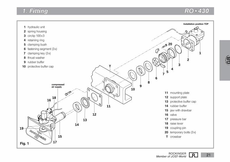
01 hydraulic unit02 spring housing03 circlip 100x304 retaining ring05 clamping bush06 fastening segment (3x)07 clamping key (3x)08 thrust washer09 rubber buffer10 protective buffer cap
11 mounting plate12 support plate13 protective buffer cap14 rubber buffer15 jaw with drawbar16 valve17 pressure bar18 raise lever19 coupling pin20 temporary bolts (3x)T crossbar
Installation position TOP
compressedair supply
GB
ROCKINGERMember of JOST-World22
11.. FFiittttiinngg RROOii443300
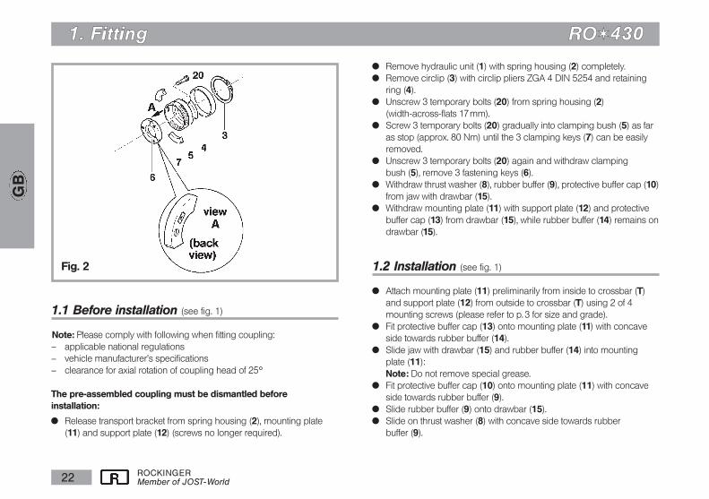
1.1 Before installation (see fig. 1)
Note: Please comply with following when fitting coupling:– applicable national regulations– vehicle manufacturer's specifications– clearance for axial rotation of coupling head of 25h
The pre-assembled coupling must be dismantled before installation:
x Release transport bracket from spring housing (2), mounting plate(11) and support plate (12) (screws no longer required).
x Remove hydraulic unit (1) with spring housing (2) completely.x Remove circlip (3) with circlip pliers ZGA 4 DIN 5254 and retaining
ring (4). x Unscrew 3 temporary bolts (20) from spring housing (2)
(width-across-flats 17mm).x Screw 3 temporary bolts (20) gradually into clamping bush (5) as far
as stop (approx. 80 Nm) until the 3 clamping keys (7) can be easilyremoved.
x Unscrew 3 temporary bolts (20) again and withdraw clamping bush (5), remove 3 fastening keys (6).
x Withdraw thrust washer (8), rubber buffer (9), protective buffer cap (10)from jaw with drawbar (15).
x Withdraw mounting plate (11) with support plate (12) and protectivebuffer cap (13) from drawbar (15), while rubber buffer (14) remains ondrawbar (15).
1.2 Installation (see fig. 1)
x Attach mounting plate (11) preliminarily from inside to crossbar (T)and support plate (12) from outside to crossbar (T) using 2 of 4mounting screws (please refer to p. 3 for size and grade).
x Fit protective buffer cap (13) onto mounting plate (11) with concaveside towards rubber buffer (14).
x Slide jaw with drawbar (15) and rubber buffer (14) into mounting plate (11): Note: Do not remove special grease.
x Fit protective buffer cap (10) onto mounting plate (11) with concaveside towards rubber buffer (9).
x Slide rubber buffer (9) onto drawbar (15).x Slide on thrust washer (8) with concave side towards rubber
buffer (9).
Fig. 2
GB

ROCKINGERMember of JOST-World 23
GB
11.. FFiittttiinngg RROOii443300
Fitting of fastening keys (see fig. 2)
Recommendation: Use fitting tool part no. 57351 (see fig. 3) for facilitating mounting when standard equipment
x Note: Locate fastening keys (6) in splines of drawbar (15): The inscribed surface in the direction of the hydraulic unit (2).
x Slide clamping bush (5) carefully over fastening keys (6) onto drawbar (15): Observe the locking snugs in clamping bush (5) and verify that boresof clamping bush (5) and fastening keys (6) mate.
x Lightly grease end face and thread of 3 temporary bolts (20), screwthem in by hand as far as stop and tighten alternately until slots inclamping bush (5) are free.
x Insert 3 clamping keys (7) into slots and hold in place.x Slide retaining ring (4) over clamping bush (5).x Fasten circlip (3) with circlip pliers ZGA 4 (see above).x Unscrew 3 temporary bolts (20) from clamping bush (5) and
fastening keys (6), generously grease and screw into spring housing (2) (required for later dismantling).
x Apply thorough coat of grease to retaining ring (4), clamping bush (5), fastening keys (6) and clamping keys (7) (to protectagainst corrosion).
x Unscrew 2 bolts from mounting plate (11).x Slide on hydraulic unit (1) with spring housing (2):
Caution: Take care not to damage bellows!x Fasten with (not supplied):
– 4 hexagon head cap screws to DIN 931, grade 8.8 or 10.9– 4 self-locking nuts to DIN 6925, grade 8 or 10Please see table for details of nut and screw size, and fig. 4 for screwlength.
�����������������Klemmlänge
Schraubenlänge
Flanschdicke
Stützplatte
Befestigungslager
4910
3
2
21
1
Federgehäuse3
Fig. 3
Fig. 4
ROCKINGERMember of JOST-World24
GB
11.. FFiittttiinngg RROOii443300
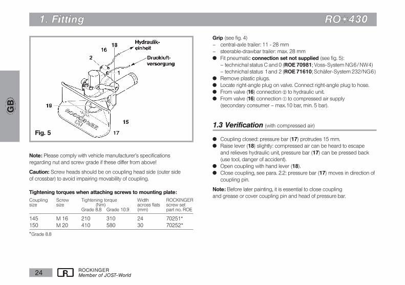
Grip (see fig. 4)– central-axle trailer: 11 - 28 mm– steerable-drawbar trailer: max. 28 mmx Fit pneumatic connection set not supplied (see fig. 5):
– technichal status C and 0 (ROE 70981; Voss-System NG6/ NW4)– technichal status 1and 2 (ROE 71610; Schäfer-System 232/NG6)
x Remove plastic plugs.x Locate right-angle plug on valve. Connect right-angle plug to hose.x From valve (16) connection Œ to hydraulic unit.x From valve (16) connection † to compressed air supply
(secondary consumer – max.10 bar, min. 5 bar).
1.3 Verification (with compressed air)
x Coupling closed: pressure bar (17) protrudes 15 mm.x Raise lever (18) slightly: compressed air can be heard to escape
and relieves hydraulic unit, pressure bar (17) can be pressed back(use tool, danger of accident).
x Open coupling with hand lever (18).x Close coupling, see para. 2.2: pressure bar (17) moves in direction of
coupling pin.
Note: Before later painting, it is essential to close coupling and grease or cover coupling pin and head of pressure bar.
Fig. 5
Note: Please comply with vehicle manufacturer's specifications regarding nut and screw grade if these differ from above!
Caution: Screw heads should be on coupling head side (outer side of crossbar) to avoid impairing movability of coupling.
Tightening torques when attaching screws to mounting plate:Coupling Screw Tightening torque Width ROCKINGERsize size (Nm) across flats screw set
Grade 8.8 Grade 10.9 (mm) part no. ROE
145 M 16 210 310 24 70251*150 M 20 410 580 30 70252*
*Grade 8.8

ROCKINGERMember of JOST-World 25
GB
22.. OOppeerraattiioonn RROOii443300
2.1 Hitching
Note: The regulations of the relevant employer's liability insurance association must be observed when hitching and unhitching.
x Push hand lever upwards (lever engages, residual area escapes via 16) for fully automatic hitching.
x Check whether funnel is locked.x Release brake on front axle of steerable-axle trailer (see fig. 6).
When hitching a central-axle trailer (see fig. 6) please note following:x Slowly reverse tractor unit.x Drawbar eye must mate with centre of funnel. If not,
this can result in damage to funnel, drawbar eye and support unit.
Fig. 6
Tractor unit with steerable-axle trailer
Tractor unit with rigid-drawbar trailer

ROCKINGERMember of JOST-World26
GB
22.. OOppeerraattiioonn RROOii443300
Check
After every hitching operation it is essential to check that the coupling is engaged as required by regulations.The check pin must be flush with its guide bush after hitching(see fig. 7/7a).If the check pin protrudes from its guide bush (this can also be established by touch if dark), this indicates that hitching has not been carried out correctly, and that you are at risk of an accident. The truck may not be driven with the trailer in this condition!
Remedy:– Advance tractor unit approx. 1 m and then reverse again.– Then check again.In-cab status indicator upgrade kit available for retrofitting.
2.2 Closing coupling manually
(e.g. for tow-rope)x Raise coupling pin with suitable tool.
orx Carefully strike hand lever knob briefly in opening direction with
heel of hand.
Fig. 7
Fig. 7a
O.K.
ROCKINGERMember of JOST-World 27
GB
33.. MMaaiinntteennaannccee RROOii443300
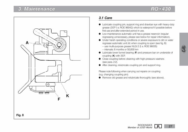
3.1 Care
x Lubricate coupling pin, support ring and drawbar eye with heavy-dutygrease (3EP f. e. ROE 96042) which is waterproof if possible beforefirst use and after extended period in use.
x Low-maintenance automatic unit has a grease reservoir (regularregreasing unnecessary, please see below for repair information).
x Under harsh operating conditions or severe exposure to dirt or waterregrease automatic unit (A) when coupling is open (see fig. 8):– use multi-purpose grease NLGI 2 (f. e. ROE 96035)– intervals: 6 months or 50,000 km
x Lubricate lower funnel bearing (F) and pressure bar on underside ofcoupling (K) with 3EP.
x Close coupling before cleaning with high-pressure washers (see para. 2.2).
x After cleaning, relubricate coupling pin and support ring.
Please note following when carrying out repairs on coupling (e.g. changing coupling pin):x Remove old grease and relubricate thoroughly (see above).
Fig. 8
ROCKINGERMember of JOST-World28
GB
33.. MMaaiinntteennaannccee RROOii443300
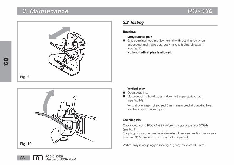
3.2 Testing
Bearings:
– Longitudinal playx Grip coupling head (not jaw funnel) with both hands when
uncoupled and move vigorously in longitudinal direction (see fig. 9):No longitudinal play is allowed.
– Vertical playx Open coupling. x Move coupling head up and down with appropriate tool
(see fig. 10):
Vertical play may not exceed 3 mm measured at coupling head (centre axis of coupling pin).
Coupling pin:
Check wear using ROCKINGER reference gauge (part no. 57026) (see fig. 11):Coupling pin may be used until diameter of crowned section has worn to less than 36.5 mm, after which it must be replaced.
Vertical play in coupling pin (see fig. 12) may not exceed 2 mm.
Fig. 9
Fig. 10
ROCKINGERMember of JOST-World 29
GB
33.. MMaaiinntteennaannccee RROOii443300
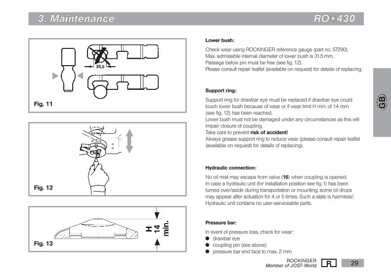
Lower bush:
Check wear using ROCKINGER reference gauge (part no. 57290).Max. admissible internal diameter of lower bush is 31.5 mm.Passage below pin must be free (see fig. 12).Please consult repair leaflet (available on request) for details of replacing.
Support ring:
Support ring for drawbar eye must be replaced if drawbar eye could touch lower bush because of wear or if wear limit H min. of 14 mm (see fig. 12) has been reached.Lower bush must not be damaged under any circumstances as this will impair closure of coupling.Take care to prevent risk of accident!Always grease support ring to reduce wear (please consult repair leaflet (available on request) for details of replacing).
Hydraulic connection:
No oil mist may escape from valve (16) when coupling is opened.In case a hydraulic unit (for installation position see fig.1) has been turned over/aside during transportation or mounting, some oil drops may appear after actuation for 4 or 5 times. Such a state is harmless!Hydraulic unit contains no user-serviceable parts.
Pressure bar:
In event of pressure loss, check for wear:x drawbar eyex coupling pin (see above)x pressure bar end face to max. 2 mm
Fig. 11
Fig. 12
Fig. 13
ı
ı
v
b

11.. FFiittttiinngg RROOii443300
ROCKINGERMember of JOST-World30
GB
M
Abb. 14
Abb. 13
R
H
R
Check lock of the funnel:
Note: The funnel must be locked in its central position when couplingis opened to be prepared for coupling on! x Push the funnel sidewardsx Move handlever in locking direction (up)x Release funnelx The funnel must swing back in central position and be locked againx If not, justify the central position by the lower unit as below.
Adjustment for technical release C and 0:
x Loosen screws (17) and bring the funnel in the central position: Spring surrounds retaining pin (M) on funnel
x Open coupling: Funnel lock should be insertedx Tighten screws (17) when the funnel is in the central position:
Tightening torque 30 Nmx Please, check the lock and movement of the funnel again
Adjustment for technical release 1 and 2:
x Loosen screws (17) and bring the funnel into the central position: x Open coupling: Funnel lock should be insertedx Tighten screws (17) – Tightening torque 30 Nm.x Both ends of torsion springs (R) must lie slack free (S) against the rib
of the funnel. Between the spring holder (H) and the lay-on points ofthe torsion springs should also be no gap.
x In case there is gap you can close it very easilyby bending the springholder with a screwdriver (M) (see fig. (S = 0).

ROCKINGERMember of JOST-World 31
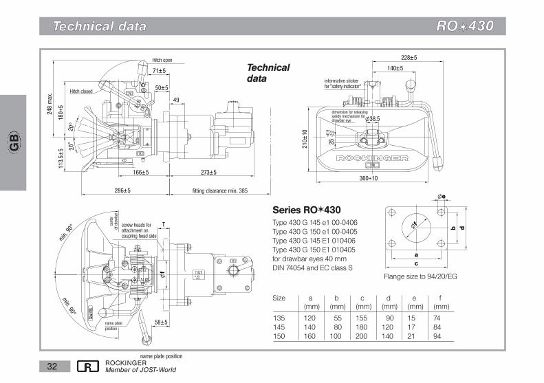
TTeecchhnniiccaall ddaattaa RROOii443300
Technicaldata
Flange size to 94/20/EG
Series ROi430Type 430 G 145 e1 00-0406Type 430 G 150 e1 00-0405 for drawbar eyes 40 mmDIN 74054 and EC class S
informative sticker for
“safety indicator”
e1 plate positionname plate
position
l38,5
24
+0,5
–2,2
360+10
210e
10
115
270e5
106e5coupling closed
name plate
coupling open
73e5
58e5
113,5e
5240 m
ax.
180+5
min
. 20h
min
.20h
166e5 273e5
fitting clearance min. 385
screw heads for attachmenton coupling head side
depositing positionfor mounting bolts
name plate position
e1 plate positionon the opposite side
286e5
GRIP T
10
min. 9
0h
cent
re li
ne
of d
raw
bar
min. 90h
49+2–1
Size a b c d e f(mm) (mm) (mm) (mm) (mm) (mm)
135 120 055 155 090 15 74145 140 080 180 120 17 84150 160 100 200 140 21 94
dimension for releasingsafety mechanism fordrawbar eye
GB
ROCKINGERMember of JOST-World32
TTeecchhnniiccaall ddaattaa RROOii443300
Technicaldata
Flange size to 94/20/EG
Size a b c d e f(mm) (mm) (mm) (mm) (mm) (mm)
135 120 055 155 090 15 74145 140 080 180 120 17 84150 160 100 200 140 21 94
GB
273±5166±5
286±5
113.5
±5180+
5
50±5
71±5
360+10
210±1
0
248 m
ax.
228±5
140±5
25
+0.5
-2.2
T
58±5
l38.5
min. 9
0°
min. 90°
20°
20°
49
lf
X XXXXX
23
1
1
2
Series ROi430Type 430 G 145 e1 00-0406Type 430 G 150 e1 00-0405 Type 430 G 145 E1 010406 Type 430 G 150 E1 010405 for drawbar eyes 40 mmDIN 74054 and EC class S
ac
lf
db
le
Hitch open
Hitch closed
informative sticker for ”safety indicator“
fitting clearance min. 385
name plate position
cent
erof
dra
wba
r
screw heads for attachment on coupling head side
dimension for releasingsafety mechanism fordrawbar eye
name plate
position

ROCKINGERMember of JOST-World 33
TTeecchhnniiccaall ddaattaa RROOii443300
part no. C E N T R A L - A X L E T R A I L E Rhand lever hand lever size hole pattern maximum maximum maximum static maximum weightupward downward D-value* Dc-value* vertical load** V-value*
(mm) (kN) (kN) (kg) (kN) (kg)
430A4500*** 430B4500*** 145 140x 80 100 91,5 1000 36 51430A5000*** 430B5000*** 150 160x 100 130 91,5 1000 36 52
*** Calculation see catalogue or internet
*** When using a central-axle trailer, the vertical load should amount to at least 4% of the trailer* **weight, in order to prevent increased wear caused by bouncing of the drawbar eye.
*** Valid for all technical status GB
ROCKINGERMember of JOST-World34
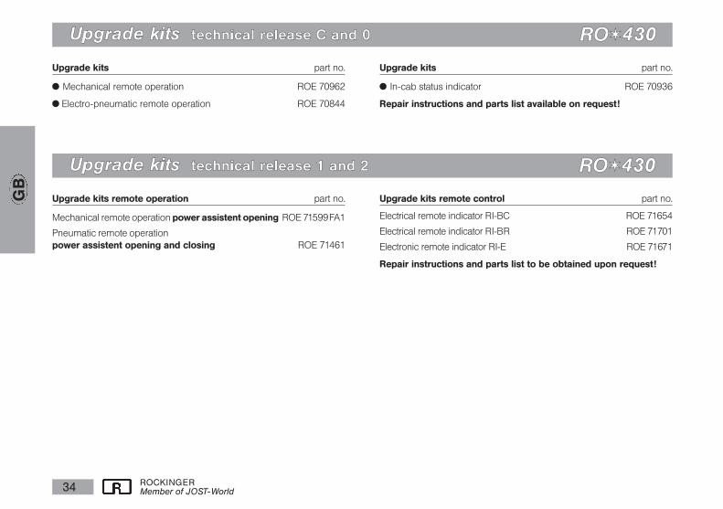
Upgrade kits part no.
x Mechanical remote operation ROE 70962
x Electro-pneumatic remote operation ROE 70844
Upgrade kits part no.
x In-cab status indicator ROE 70936
Repair instructions and parts list available on request!
UUppggrraaddee kkiittss tteecchhnniiccaall rreelleeaassee CC aanndd 00 RROOii443300
Upgrade kits remote operation part no.
Mechanical remote operation power assistent opening ROE 71599FA1
Pneumatic remote operationpower assistent opening and closing ROE 71461
Upgrade kits remote control part no.
Electrical remote indicator RI-BC ROE 71654
Electrical remote indicator RI-BR ROE 71701
Electronic remote indicator RI-E ROE 71671
Repair instructions and parts list to be obtained upon request!
UUppggrraaddee kkiittss tteecchhnniiccaall rreelleeaassee 11 aanndd 22 RROOii443300
GB
JOST-Werke · Siemensstr. 2, D-63263 Neu-Isenburg · Telefon +49(0)61 02 2 95-0 · Fax +49(0)61 02 2 95-298 · www.jost-world.comZDE 199 88 215-2-020 · 07/2011
8821
5-2-
020
KE
MA
071
1 D
/GB
/F