series sh/shg stainless steel hydraulic cylindersesmagroup.com/products/automation/parker atlas...
TRANSCRIPT
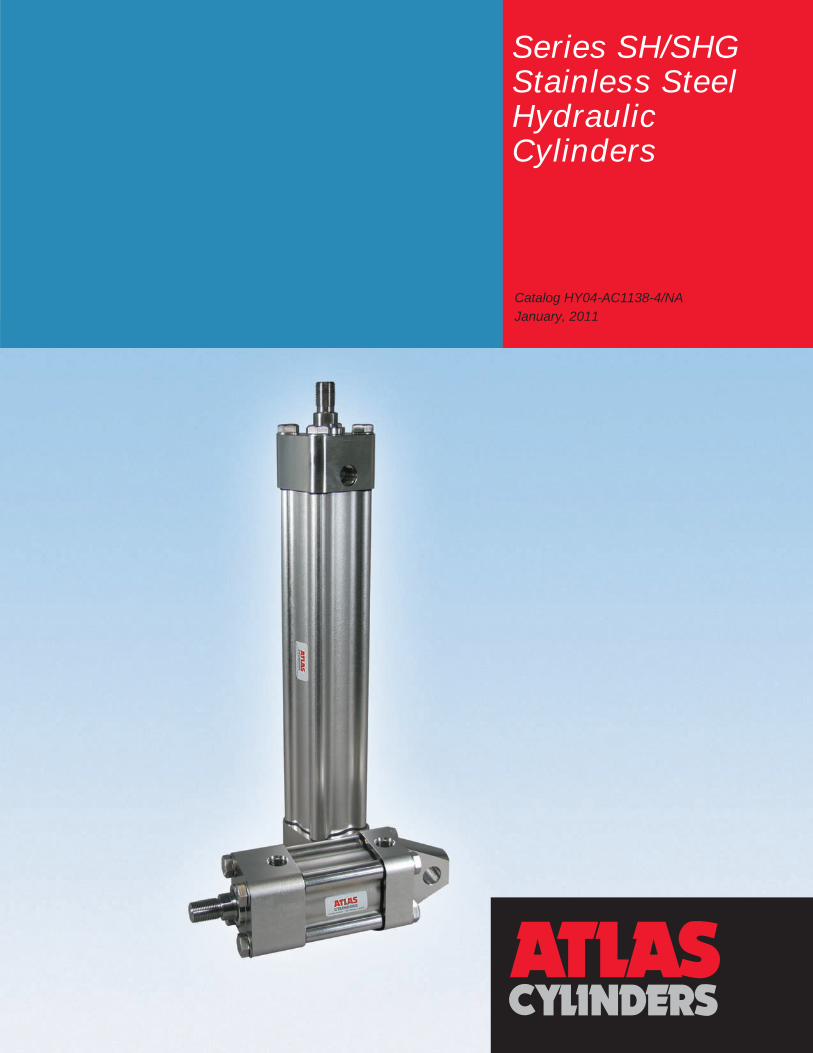
Series SH/SHGStainless Steel Hydraulic Cylinders
Catalog HY04-AC1138-4/NAJanuary, 2011
Heavy-Duty Stainless Steel Hydraulic CylindersSeries SH/SHG
Catalog HY04-AC1138-4/NA
� Atlas CylindersDes Plaines, IL USA
www.AtlasCylinders.com
Features, Benefits, Value
Atlas CylindersDes Plaines, IL USA
www.AtlasCylinders.com
Heavy-Duty Stainless Steel Hydraulic CylindersSeries SH/SHG
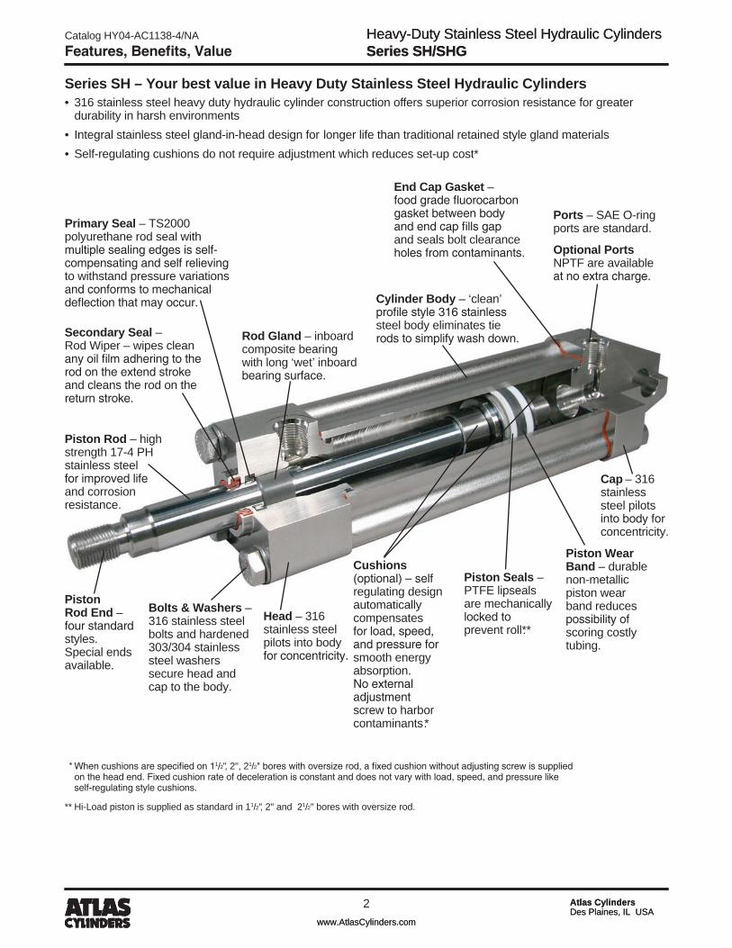
* When cushions are specified on 11/�", �", �1/�" bores with oversize rod, a fixed cushion without adjusting screw is supplied on the head end. Fixed cushion rate of deceleration is constant and does not vary with load, speed, and pressure like self-regulating style cushions.
** Hi-Load piston is supplied as standard in 11/�", �" and �1/�" bores with oversize rod.
Series SH – Your best value in Heavy Duty Stainless Steel Hydraulic Cylinders• 316stainlesssteelheavydutyhydrauliccylinderconstructionofferssuperiorcorrosionresistanceforgreater durabilityinharshenvironments• Integralstainlesssteelgland-in-headdesignforlongerlifethantraditionalretainedstyleglandmaterials• Self-regulatingcushionsdonotrequireadjustmentwhichreducesset-upcost*
Primary Seal – TS�000 polyurethane rod seal with multiple sealing edges is self-compensating and self relieving to withstand pressure variations and conforms to mechanical deflection that may occur.
Ports – SAE O-ring ports are standard.
Optional Ports NPTF are available at no extra charge.
Secondary Seal – Rod Wiper – wipes clean any oil film adhering to the rod on the extend stroke and cleans the rod on the return stroke.
Head – 316 stainless steel pilots into body for concentricity.
Rod Gland – inboard composite bearing with long ‘wet’ inboard bearing surface.
Piston Rod End – four standard styles. Special ends available.
Cylinder Body – ‘clean’ profile style 316 stainless steel body eliminates tie rods to simplify wash down.
Cushions (optional) – self regulating design automatically compensates for load, speed, and pressure for smooth energy absorption. No external adjustment screw to harbor contaminants.*
Cap – 316 stainless steel pilots into body for concentricity.
Bolts & Washers – 316 stainless steel bolts and hardened 303/304 stainless steel washers secure head and cap to the body.
Piston Rod – high strength 17-4 PH stainless steel for improved life and corrosion resistance.
Piston Wear Band – durable non-metallic piston wear band reduces possibility of scoring costly tubing.
Piston Seals – PTFE lipseals are mechanically locked to prevent roll**.
End Cap Gasket – food grade fluorocarbon gasket between body and end cap fills gap and seals bolt clearance holes from contaminants.

Catalog HY04-AC1138-4/NA
3
Heavy-Duty Stainless Steel Hydraulic CylindersSeries SH/SHG
Atlas CylindersDes Plaines, IL USA
www.AtlasCylinders.com
Features, Benefits, ValueFeatures, Benefits, Value
Series SHG – Your best value in heavy duty hydraulic cylinders for food processing applicationsIn addition to features of Series SH cylinders, Series SHG includes exterior surfaces that are electropolished, food grade wiperseal material, Stat-O-Seal™ washers under bolt heads for maximum protection against contamination, and assembly with H-1 rated lubricant.
Series SHG Feature Series SHG ValueBenefit
Rounded Corners on Head and Cap and “Clean” Profile Body
without Tie Rods
Material does not collect around cylinder tie rods or build up on head and cap surfaces.
Extruded construction simplifies repairability compared to tie rod style.
Wash down time is reduced with 'clean' profile style body and rounded head and cap corners.
Equipment down time for repair is reduced.
Standard PTFE Piston Seals with Non-Metallic
Piston Wear Band
PTFE piston seals have greater fluid and temperature resistance than elastomeric seals.
Non-metallic wear band for greater protection against scoring costly tubing.
Longer piston seal and tube life than typical cylinders used in food processing applications.
Self-Regulating Cushions
Automatic compensation for load, speed, and pressure ensures optimal cushion performance. Saves manual adjustment labor.
No needle or check valve cavities to collect contamination.
Time required for machine set-up, operational adjustments and cleaning is reduced.
Electropolished Cylinder Exterior
Electropolishing significantly improves corrosion resistance and improves surface condition to resist bacteria.
Reduced corrosion increases cylinder life and replacement interval.
Added bacterial resistance promotes better food handling practices.
Integral Gland with Food Grade Wiperseal
Integral stainless steel gland with inboard bearing is more corrosion resistant than traditional retained style gland materials. Food grade wiperseal accepts food contact.
Gland service interval is increased which reduces maintenance cost.
USDA H-1 Rated Fluid Used for Cylinder
Assembly Lubrication and Testing
Eliminates possibility of hydraulic system contamination by unknown lubricants from the cylinder.
Reduced setup time by eliminating need to purge cylinder.

Heavy-Duty Stainless Steel Hydraulic CylindersSeries SH/SHG
Catalog HY04-AC1138-4/NA
4 Atlas CylindersDes Plaines, IL USA
www.AtlasCylinders.com
Table of Contents
Table of Contents Page No.SH Cylinder Features ..................................................................................................................Inside Front Cover
SHG Cylinder Features ............................................................................................................................................1
Model Numbers – How to Develop and Decode Them .........................................................................................3
Standard Specifications ...........................................................................................................................................3
Theoretical Output, Maximum Pressures ...............................................................................................................4
Cylinder Weights ......................................................................................................................................................5
T, TB, TC, TD Mount Dimensions – Single Rod End .............................................................................................6
T, TB, TD Mount Dimensions – Double Rod End ..................................................................................................7
JJ Mount Dimensions – Single Rod End ................................................................................................................8
JJ Mount Dimensions – Double Rod End ...............................................................................................................9
HH Mount Dimensions – Single Rod End ............................................................................................................ 10
BE Mount Dimensions – Single Rod End ............................................................................................................ 11
F Mount Dimensions – Single Rod End ............................................................................................................... 1�
F Mount Dimensions – Double Rod End ............................................................................................................. 13
D Mount Dimensions – Single Rod End .............................................................................................................. 14
D Mount Dimensions – Double Rod End ............................................................................................................. 15
Mounting Accessories ..................................................................................................................................... 16, 17
Stop Tubing, Mounting Classes ........................................................................................................................... 18
Cylinder Stroke Chart ............................................................................................................................................ 19
Parts List ................................................................................................................................................................ �0
Thrust Key Mounting ............................................................................................................................................. �0
Parts Identification / Seal Kits ............................................................................................................................... �1
Cylinder Safety Guide ..................................................................................................................................... ��, �3
Offer of Sale........................................................................................................................................................... �4
Offer of SaleThe items described in this document are hereby offered for sale by The Company, its subsidiaries or its authorized distributors. This offer and its acceptance are governed by provisions stated on a separate page of the document entitled ‘Offer of Sale’.
WarningFAILURE OR IMPROPER SELECTION OR IMPROPER USE OF THE PRODUCTS AND/OR SYSTEMS DESCRIBED HEREIN OR RELATED ITEMS CAN CAUSE DEATH, PERSONAL INJURY AND PROPERTY DAMAGE.
This document and other information from The Company, its subsidiaries and authorized distributors provide product and/or system options for further investigation by users having technical expertise. It is important that you analyze all aspects of your application, including consequences of any failure and review the information concerning the product or system in the current product catalog. Due to the variety of operating conditions and applications for these products or systems, the user, through its own analysis and testing, is solely responsible for making the final selection of the products and systems and assuring that all performance, safety and warning requirements of the application are met.
The product described herein, including without limitation, product features, specifications, designs, availability and pricing, are subject to change by The Company and its subsidiaries at any time without notice.

Catalog HY04-AC1138-4/NA
5
Heavy-Duty Stainless Steel Hydraulic CylindersSeries SH/SHG
Atlas CylindersDes Plaines, IL USA
www.AtlasCylinders.com
Model Code & Standard Specifications
Standard Specifications• 6 Standard mounting styles• Bore sizes – 11/�" to 4"• Strokes – up to 72"• Piston Rod Diameters – 5/8" to �1/�"
• Working pressure up to 3000 psi• Single and double rod construction available• Temperature range – -10°F (-�3°C) to +�50°F (+1�1°C) (depending on seal class)
Seal Classes1 – Standard Nitrile, Polyurethane & PTFE
5 – Optional (At extra cost) Fluorocarbon Seals
Typical FluidsISO Grade 32 NSF / USDA H-1 Oils (Acceptable for use in Food Industry) – Approved products include Chevron FM32, Petro-Canada Purity FG AW32, Mobil DTE FM3�, ConocoPhillips �00Hydraulic Oil, MIL-H-5606 Oil
High Temperature
Note: Class 5 seals are not suitable for use with Skydrol fluid, but can be used with hydraulic oil if desired. Rod seal, wiperseal, and body o-rings are fluorocarbon; piston seals are spring loaded PTFE. Contact the factory before specifying Series SH or SHG for use with phosphate ester fluid.
Model Ordering Code for SH and SHG
Temperature Range-10°F (-�3°C) to +165°F (+74°C)
-10°F (-�3°C) to +�50°F (+1�1°C) Class 5 seals may be operated up to +400°F (+204°C) with reduced service life
Double Rod CylindersFor double rod cylinders, specify rod number and rod end symbols for both piston rods. A typical double rod model number would be:2" KJJ-SHGLT14A/14AX12"
2" C BE SHG L* T 1 4 A 12.000
BoreSize
CushionHead
Double Rod
CylinderMounting
Style
Series
Piston
Ports
Common Modifications
Piston Rod Number
Piston Rod Thread Style
Piston Rod Thread Type
Stroke
Specify bore size in inches
11/��
�1/�31/44
Use “K” only if double rod cylinder is required.
Specify: T = No tie rods extendedTB = Tie rods ext. headTC = Tie rods ext. capTD = Tie rods extended both ends JJ = Head rectangularHH = Cap rectangular BE = Cap eye F = Side tapped D = Head trunnion
SHG = Food Grade Stainless Steel CylinderSH = Standard Stainless Steel Cylinder
L = Lipseal Piston
Specify:T = SAE PortsU = NPTF PortsR = BSPP Ports
V = Fluorocarbon
For Single Rod Cylinders, select one rod number only. Refer to rod number listing on pages 6 thru 15. See Cylinder Stroke Chart on page 19 for minimum piston rod diameter.
Specify: 4 = Small Male 8 = Intermediate Male 9 = Female55 = Flange Coupler 3 = Special(see note below)
Specify:A = UNFM = Metric
Specify Stroke Length Required in inches.
* ‘K’ Hi-Load piston is supplied as standard for 11/�", �" & �1/�" bores with oversize rods and is not available in any other bore and rod combination.
Special Modifications
Use “S” for Special Modifica-tion other than rod end, and specify modification.
C
Cushion Cap
To order special thread specify “3” and give the desired dimensions for KK, A, and W (WD for D mount or WF for JJ mount) or furnish a dimensioned sketch.
Use “C” only if head end cushion is required.
Use “C” only if cap end cushion is required.

Heavy-Duty Stainless Steel Hydraulic CylindersSeries SH/SHG
Catalog HY04-AC1138-4/NA
6 Atlas CylindersDes Plaines, IL USA
www.AtlasCylinders.com
Theoretical Push and Pull Forces
Theoretical Push and Pull ForcesThe cylinder output forces are derived from this formula:
F = P x A
Where F = Force in pounds. P = Pressure at the cylinder in pounds per square inch. A = Effective area of cylinder piston in square inches.
To determine the bore size for the application, follow the steps below.
1. Select the Operating Pressure column closest to that desired.
2. In the same column, identify the force required to move the load (always rounding up). If the piston rod is in compression use the ‘Push’ row and if the piston rod is in tension use the ‘Pull’ row.
3. In the row to the left is the bore required. To select the correct rod diameter for the stroke required use the Piston Rod-Stroke Selection Chart on page 19.
If the cylinder envelope dimensions are too large for the application, increase the operating pressure to the maximum pressure in the table below, if possible, and repeat steps 1 - 3.
Pressure RatingsSeries SH and SHG hydraulic cylinders are recom-mended for pressures to 3000 psi for heavy-duty hydraulic service with hydraulic oil.
Maximum Pressure Ratings
1 1/2 5/8, 1 30002 1, 1 3/8 3000
2 1/2 1, 1 3/4 30003 1/4 1 3/8, 2 3000
4 1 3/4, 2 1/2 3000
Heavy Duty Service (psi)
RodØ
BoreØ
Push and Pull Force in Pounds
100 250 500 1000 2000 3000Push 1.767 177 442 884 1767 3534 5301Pull 1.460 146 365 730 1460 2920 4380
Push 1.767 177 442 884 1767 3534 5301Pull 0.982 98 246 491 982 1964 2946
Push 3.142 314 786 1571 3142 6284 9426Pull 2.357 236 589 1179 2357 4714 7071
Push 3.142 314 786 1571 3142 6284 9426Pull 1.652 165 413 826 1652 3304 4956
Push 4.909 491 1227 2455 4909 9818 14727Pull 4.124 412 1031 2062 4124 8248 12372
Push 4.909 491 1227 2455 4909 9818 14727Pull 2.499 250 625 1250 2499 4998 7497
Push 8.296 830 2074 4148 8296 16592 24888Pull 6.806 681 1702 3403 6806 13612 20418
Push 8.296 830 2074 4148 8296 16592 24888Pull 5.154 515 1289 2577 5154 10308 15462
Push 12.566 1257 3142 6283 12566 25132 37698Pull 10.156 1016 2539 5078 10156 20312 30468
Push 12.566 1257 3142 6283 12566 25132 37698Pull 7.656 766 1914 3828 7656 15312 22968
2
1 1/2
BoreØ
2 1/2
3 1/4
4
1 3/8
2
1
1 3/42 1/2
1 3/4
Piston Area (inches²)
Operating Pressure in psi
1
1 3/8
5/8
1
RodØ
OperatingDirection

Catalog HY04-AC1138-4/NA
7
Heavy-Duty Stainless Steel Hydraulic CylindersSeries SH/SHG
Atlas CylindersDes Plaines, IL USA
www.AtlasCylinders.com
Cylinder Weights
Cylinder WeightsTo determine the weight of a Series SH or SHG cylinder, first select the basic zero stroke weight for the mounting required, and then calculate the weight of the
cylinder stroke and add the results to the basic weight. For extra rod extension, use piston rod weights per inch in Table C.
Table A – Single Rod End SH & SHG Cylinder Weights in Pounds
T, TB, TC,TD, F
JJ D BE HH
5/8 7.3 9.1 7.8 7.7 8.4 0.71 8.2 10.0 8.6 8.6 9.3 0.81 11.8 14.8 13.1 12.9 13.4 1.1
1 3/8 13.3 16.3 14.5 14.4 14.8 1.31 17.1 20.7 18.3 18.6 19.0 1.6
1 3/4 20.7 24.3 21.9 22.2 22.6 2.01 3/8 33.5 40.2 36.0 36.3 37.1 2.4
2 37.6 44.4 40.2 40.5 41.2 2.91 3/4 45.8 53.8 48.2 51.8 49.9 3.22 1/2 53.4 61.4 55.8 59.4 57.5 3.9
Add PerInch
of Stroke
1 1/2
2
2 1/2
BoreØ
RodØ
Single Rod CylindersBasic Weight - Zero Stroke
3 1/4
4
Table B – Double Rod End SH & SHG Cylinder Weights in Pounds
KT, KTB,KTD, KF KJJ KD
5/8 8.7 10.5 9.2 0.81 10.5 12.3 11.0 1.11 14.7 17.7 16.0 1.3
1 3/8 17.6 20.6 18.8 1.71 20.8 24.4 22.1 1.8
1 3/4 28.0 31.6 29.2 2.71 3/8 40.8 47.6 43.4 2.8
2 49.2 55.9 51.7 3.81 3/4 56.9 65.0 59.3 3.92 1/2 72.1 80.2 74.5 5.3
2
2 1/2
BoreØ
Double Rod CylindersBasic Weight - Zero Stroke
Add PerInch
of Stroke
1 1/2
RodØ
3 1/4
4
Table C – Piston Rod Weights in PoundsRod
ØPiston Rod
Weight Per Inch5/8 0.091 0.22
1 3/8 0.421 3/4 0.68
2 0.892 1/2 1.40

Heavy-Duty Stainless Steel Hydraulic CylindersSeries SH/SHG
Catalog HY04-AC1138-4/NA
8 Atlas CylindersDes Plaines, IL USA
www.AtlasCylinders.com
T, TB, TC, TD Mount – Single Rod End
T, TB, TC, TD Mount Single Rod End – Envelope and Mounting Dimensions
“Special” Thread Style 3Special thread, extension, rod eye, blank, etc. are also available. To order, specify “Style 3” and give desired dimensions for KK, A, & W. If otherwise special furnish dimensional sketch.
T, TB, TC, TD Mount Single Rod End – Rod Dimensions
TD Mount – Single Rod End* 11/�" to 4" Bore Size
1
2
3
4
E
E R
RØ AA GBBDD
Ø MM
W LB + STROKE KEE
Y P + STROKEZJ + STROKEZB + STROKE
J BB
NPTF SAE LB P1 1/2 2.3 1 3/8 3/8-24 2 1/2 1/2 8 1 3/4 1 1/8 7/16 1.63 5 3 1/4
2 2.9 1 13/16 1/2-20 3 1/2 8 2 1 1/8 1/2 2.05 5 1/4 3 5/162 1/2 3.6 1 13/16 1/2-20 3 1/2 1/2 8 2 1 1/8 1/2 2.55 5 3/8 3 7/163 1/4 4.6 2 5/16 5/8-18 4 1/2 3/4 10 2 3/8 1 3/8 5/8 3.25 6 1/4 3 15/16
4 5.4 2 5/16 5/8-18 5 3/4 12 2 1/2 1 3/8 5/8 3.82 6 5/8 4 1/4
BBAABoreØ
G Add StrokeEEEDD J KMax
R
A AD AE AF AM B +.000-.002
C D NA V W WH
1 5/8 3/4 5/8 1/4 3/8 0.57 1.124 3/8 1/2 9/16 1/4 5/8 3/42 1 1 1/8 15/16 3/8 11/16 0.95 1.499 1/2 7/8 15/16 1/2 1 1 1/161 1 1 1/8 15/16 3/8 11/16 0.95 1.499 1/2 7/8 15/16 1/4 3/4 13/162 1 3/8 1 5/8 1 1/16 3/8 7/8 1.32 1.999 5/8 1 1/8 1 5/16 3/8 1 1 1/161 1 1 1/8 15/16 3/8 11/16 0.95 1.499 1/2 7/8 15/16 1/4 3/4 13/162 1 3/4 2 1 5/16 1/2 1 1/8 1.70 2.374 3/4 1 1/2 1 11/16 1/2 1 1/4 1 3/161 1 3/8 1 5/8 1 1/16 3/8 7/8 1.32 1.999 5/8 1 1/8 1 5/16 1/4 7/8 15/162 2 2 1/4 1 11/16 5/8 1 3/8 1.95 2.624 7/8 1 11/16 1 15/16 3/8 1 1/4 1 5/161 1 3/4 2 1 5/16 1/2 1 1/8 1.70 2.374 3/4 1 1/2 1 11/16 1/4 1 15/162 2 1/2 3 1 15/16 3/4 1 3/4 2.45 3.124 1 2 1/16 2 3/8 3/8 1 3/8 1 11/16
Rod Extensions and Pilot DimensionsMMRod
Ø
Rod No.BoreØ
1 1/2
2
2 1/2
3 1/4
4
Style 8CC
Style4 & 9KK
ZB ZJ Style 8CC
Style4 & 9KK
ZB ZJ
1 5/8 1/2-20 7/16-20 1 13/16 6 1/16 5 5/8 1 1 3/8 1 1/4-12 1-14 2 1/2 7 3/4 7 1/82 1 7/8-14 3/4-16 2 3/16 6 7/16 6 2 2 1 3/4-12 1 1/2-12 2 7/8 8 1/8 7 1/21 1 7/8-14 3/4-16 2 1/8 6 1/2 6 1 1 3/4 1 1/2-12 1 1/4-12 2 11/16 8 1/4 7 5/82 1 3/8 1 1/4-12 1-14 2 3/8 6 3/4 6 1/4 2 2 1/2 2 1/4-12 1 7/8-12 3 1/16 8 5/8 81 1 7/8-14 3/4-16 2 1/8 6 5/8 6 1/82 1 3/4 1 1/2-12 1 1/4-12 2 5/8 7 1/8 6 5/8
Add Stroke
1 1/2
2
2 1/2
MMRod
Ø
Y Add StrokeBoreØ
RodNo.
3 1/4
4
Thread YThread Bore Ø
RodNo.
MMRod
Ø
* Style T – no tie rods extended, Style TB – tie rods extended head end, and Style TC – tie rods extended cap end can be dimensioned from Style TD shown.
Rod End DimensionsThread Style 8 Thread Style 9Thread Style 4 Style 55
DWRENCH
FLATS
KK
Ø NA
A WC V
Ø B Ø MM
CC
V
Ø B
Ø NA
A W
C
Ø MM
DWRENCH
FLATS
KKØ B
WC
Ø NA
V
A
Ø MM
DWRENCH
FLATS R 1/16
Ø B
Ø AM
Ø AF
AE
AD WHV
Ø MM
Catalog HY04-AC1138-4/NA
9
Heavy-Duty Stainless Steel Hydraulic CylindersSeries SH/SHG
Atlas CylindersDes Plaines, IL USA
www.AtlasCylinders.com
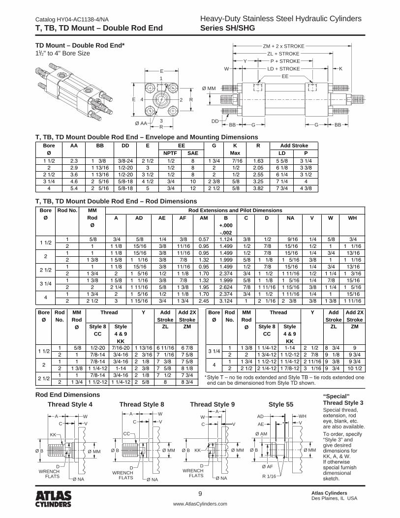
T, TB, TD Mount – Double Rod End
“Special” Thread Style 3Special thread, extension, rod eye, blank, etc. are also available. To order, specify “Style 3” and give desired dimensions for KK, A, & W. If otherwise special furnish dimensional sketch.
TD Mount – Double Rod End* 11/�" to 4" Bore Size
1
2
3
4
E
E
R
R
GØ AA G BBBB
Ø MM
WEE
LD + STROKE KP + STROKEY
ZM + 2 x STROKEZL + STROKE
DD
NPTF SAE LD P1 1/2 2.3 1 3/8 3/8-24 2 1/2 1/2 8 1 3/4 7/16 1.63 5 5/8 3 1/4
2 2.9 1 13/16 1/2-20 3 1/2 8 2 1/2 2.05 6 1/8 3 3/82 1/2 3.6 1 13/16 1/2-20 3 1/2 1/2 8 2 1/2 2.55 6 1/4 3 1/23 1/4 4.6 2 5/16 5/8-18 4 1/2 3/4 10 2 3/8 5/8 3.25 7 1/4 4
4 5.4 2 5/16 5/8-18 5 3/4 12 2 1/2 5/8 3.82 7 3/4 4 3/8
R Add StrokeEEEDD KMax
BoreØ
GBBAAT, TB, TD Mount Double Rod End – Envelope and Mounting Dimensions
T, TB, TD Mount Double Rod End – Rod Dimensions
A AD AE AF AM B +.000-.002
C D NA V W WH
1 5/8 3/4 5/8 1/4 3/8 0.57 1.124 3/8 1/2 9/16 1/4 5/8 3/42 1 1 1/8 15/16 3/8 11/16 0.95 1.499 1/2 7/8 15/16 1/2 1 1 1/161 1 1 1/8 15/16 3/8 11/16 0.95 1.499 1/2 7/8 15/16 1/4 3/4 13/162 1 3/8 1 5/8 1 1/16 3/8 7/8 1.32 1.999 5/8 1 1/8 1 5/16 3/8 1 1 1/161 1 1 1/8 15/16 3/8 11/16 0.95 1.499 1/2 7/8 15/16 1/4 3/4 13/162 1 3/4 2 1 5/16 1/2 1 1/8 1.70 2.374 3/4 1 1/2 1 11/16 1/2 1 1/4 1 3/161 1 3/8 1 5/8 1 1/16 3/8 7/8 1.32 1.999 5/8 1 1/8 1 5/16 1/4 7/8 15/162 2 2 1/4 1 11/16 5/8 1 3/8 1.95 2.624 7/8 1 11/16 1 15/16 3/8 1 1/4 1 5/161 1 3/4 2 1 5/16 1/2 1 1/8 1.70 2.374 3/4 1 1/2 1 11/16 1/4 1 15/162 2 1/2 3 1 15/16 3/4 1 3/4 2.45 3.124 1 2 1/16 2 3/8 3/8 1 3/8 1 11/16
Rod Extensions and Pilot DimensionsMMRod
Ø
Rod No.BoreØ
4
1 1/2
2
2 1/2
3 1/4
AddStroke
Add 2XStroke
AddStroke
Add 2XStroke
Style 8CC
Style4 & 9KK
ZL ZM Style 8CC
Style4 & 9KK
ZL ZM
1 5/8 1/2-20 7/16-20 1 13/16 6 11/16 6 7/8 1 1 3/8 1 1/4-12 1-14 2 1/2 8 3/4 92 1 7/8-14 3/4-16 2 3/16 7 1/16 7 5/8 2 2 1 3/4-12 1 1/2-12 2 7/8 9 1/8 9 3/41 1 7/8-14 3/4-16 2 1/8 7 3/8 7 5/8 1 1 3/4 1 1/2-12 1 1/4-12 2 11/16 9 3/8 9 3/42 1 3/8 1 1/4-12 1-14 2 3/8 7 5/8 8 1/8 2 2 1/2 2 1/4-12 1 7/8-12 3 1/16 9 3/4 10 1/21 1 7/8-14 3/4-16 2 1/8 7 1/2 7 3/42 1 3/4 1 1/2-12 1 1/4-12 2 5/8 8 8 3/4
2
2 1/2
MMRod
Ø
BoreØ
RodNo.
3 1/41 1/2
4
Thread YThread Bore Ø
RodNo.
MMRod
Ø
Y
* Style T – no tie rods extended and Style TB – tie rods extended one end can be dimensioned from Style TD shown.
Rod End DimensionsThread Style 8 Thread Style 9Thread Style 4 Style 55
DWRENCH
FLATS
KK
Ø NA
A WC V
Ø B Ø MM
CC
V
Ø B
Ø NA
A W
C
Ø MM
DWRENCH
FLATS
KKØ B
WC
Ø NA
V
A
Ø MM
DWRENCH
FLATS R 1/16
Ø B
Ø AM
Ø AF
AE
AD WHV
Ø MM

Heavy-Duty Stainless Steel Hydraulic CylindersSeries SH/SHG
Catalog HY04-AC1138-4/NA
10 Atlas CylindersDes Plaines, IL USA
www.AtlasCylinders.com
JJ Mount – Single Rod End
JJ Mount Single Rod End – Envelope and Mounting Dimensions
JJ Mount Single Rod End – Rod Dimensions
JJ Mount – Single Rod End 11/�" to 4" Bore Size
NPTF SAE LB P1 1/2 2 1/2 1/2 8 7/16 1 3/4 1 1/8 7/16 1.63 3 7/16 4 1/4 5 3 1/4
2 3 1/2 8 9/16 2 1 1/8 1/2 2.05 4 1/8 5 1/8 5 1/4 3 5/162 1/2 3 1/2 1/2 8 9/16 2 1 1/8 1/2 2.55 4 5/8 5 5/8 5 3/8 3 7/163 1/4 4 1/2 3/4 10 11/16 2 3/8 1 3/8 5/8 3.25 5 7/8 7 1/8 6 1/4 3 15/16
4 5 3/4 12 11/16 2 1/2 1 3/8 5/8 3.82 6 3/8 7 5/8 6 5/8 4 1/4
EBoreØ
Add StrokeEE FB KMax
RG J TF UF
1
2
3
4
TF
E
UF
R
E
Ø FB4 HOLES
Ø MM
G
WFYJ
EELB + STROKEP + STROKE
K
ZN + STROKE
J
A AD AE AF AM B +.000-.002
C D NA V WF WK
1 5/8 3/4 5/8 1/4 3/8 0.57 1.124 3/8 1/2 9/16 1/4 1 1 1/82 1 1 1/8 15/16 3/8 11/16 0.95 1.499 1/2 7/8 15/16 1/2 1 3/8 1 7/161 1 1 1/8 15/16 3/8 11/16 0.95 1.499 1/2 7/8 15/16 1/4 1 3/8 1 7/162 1 3/8 1 5/8 1 1/16 3/8 7/8 1.32 1.999 5/8 1 1/8 1 5/16 3/8 1 5/8 1 11/161 1 1 1/8 15/16 3/8 11/16 0.95 1.499 1/2 7/8 15/16 1/4 1 3/8 1 7/162 1 3/4 2 1 5/16 1/2 1 1/8 1.70 2.374 3/4 1 1/2 1 11/16 1/2 1 7/8 1 13/161 1 3/8 1 5/8 1 1/16 3/8 7/8 1.32 1.999 5/8 1 1/8 1 5/16 1/4 1 5/8 1 11/162 2 2 1/4 1 11/16 5/8 1 3/8 1.95 2.624 7/8 1 11/16 1 15/16 3/8 2 2 1/161 1 3/4 2 1 5/16 1/2 1 1/8 1.70 2.374 3/4 1 1/2 1 11/16 1/4 1 7/8 1 13/162 2 1/2 3 1 15/16 3/4 1 3/4 2.45 3.124 1 2 1/16 2 3/8 3/8 2 1/4 2 9/16
BoreØ
Rod Extensions and Pilot Dimensions
4
1 1/2
2
2 1/2
3 1/4
MMRod
Ø
RodNo.
Add Stroke Add StrokeStyle 8
CCStyle4 & 9KK
ZN Style 8CC
Style4 & 9KK
ZN
1 5/8 1/2-20 7/16-20 2 3/16 6 7/16 1 1 3/8 1 1/4-12 1-14 3 1/4 8 1/22 1 7/8-14 3/4-16 2 9/16 6 13/16 2 2 1 3/4-12 1 1/2-12 3 5/8 8 7/81 1 7/8-14 3/4-16 2 3/4 7 1/8 1 1 3/4 1 1/2-12 1 1/4-12 3 9/16 9 1/82 1 3/8 1 1/4-12 1-14 3 7 3/8 2 2 1/2 2 1/4-12 1 7/8-12 3 15/16 9 1/21 1 7/8-14 3/4-16 2 3/4 7 1/42 1 3/4 1 1/2-12 1 1/4-12 3 1/4 7 3/4
YJThread Thread
2 4
2 1/2
RodNo.
MMRod
Ø
BoreØ
RodNo.
MMRod
Ø
1 1/2
YJ Bore Ø
3 1/4
Rod End DimensionsThread Style 8 Thread Style 9Thread Style 4
“Special” Thread Style 3Special thread, extension, rod eye, blank, etc. are also available. To order, specify “Style 3” and give desired dimensions for KK, A, & WF. If otherwise special furnish dimensional sketch.
Style 55
DWRENCH
FLATS
KK
Ø NA
A WF
CV
Ø B Ø MM
V
Ø B
Ø NA
A WF
C
Ø MM
DWRENCH
FLATS
CC
KKØ B
WF
C
Ø NA
V
A
Ø MM
DWRENCH
FLATS R 1/16
Ø B
Ø AM
Ø AF
AE
AD WKV
Ø MM

Catalog HY04-AC1138-4/NA
11
Heavy-Duty Stainless Steel Hydraulic CylindersSeries SH/SHG
Atlas CylindersDes Plaines, IL USA
www.AtlasCylinders.com
JJ Mount – Double Rod End
JJ Mount – Double Rod End 11/�" to 4" Bore Size
JJ Mount Double Rod End – Envelope and Mounting Dimensions
JJ Mount Double Rod End – Rod Dimensions
1
2
3
4
UF
E R
TFØ FB4 HOLES
Ø MM
G
WF LD + STROKEEE
P + STROKEYJ
ZR + 2 x STROKE
G
E K
ZP + STROKE
NPTF SAE LD P1 1/2 2 1/2 1/2 8 7/16 1 3/4 7/16 1.63 3 7/16 4 1/4 5 5/8 3 1/4
2 3 1/2 8 9/16 2 1/2 2.05 4 1/8 5 1/8 6 1/8 3 3/82 1/2 3 1/2 1/2 8 9/16 2 1/2 2.55 4 5/8 5 5/8 6 1/4 3 1/23 1/4 4 1/2 3/4 10 11/16 2 3/8 5/8 3.25 5 7/8 7 1/8 7 1/4 4
4 5 3/4 12 11/16 2 1/2 5/8 3.82 6 3/8 7 5/8 7 3/4 4 3/8
BoreØ
Add StrokeEE FB KMax
RG TF UFE
A AD AE AF AM B +.000-.002
C D NA V WF WK
1 5/8 3/4 5/8 1/4 3/8 0.57 1.124 3/8 1/2 9/16 1/4 1 1 1/82 1 1 1/8 15/16 3/8 11/16 0.95 1.499 1/2 7/8 15/16 1/2 1 3/8 1 7/161 1 1 1/8 15/16 3/8 11/16 0.95 1.499 1/2 7/8 15/16 1/4 1 3/8 1 7/162 1 3/8 1 5/8 1 1/16 3/8 7/8 1.32 1.999 5/8 1 1/8 1 5/16 3/8 1 5/8 1 11/161 1 1 1/8 15/16 3/8 11/16 0.95 1.499 1/2 7/8 15/16 1/4 1 3/8 1 7/162 1 3/4 2 1 5/16 1/2 1 1/8 1.70 2.374 3/4 1 1/2 1 11/16 1/2 1 7/8 1 13/161 1 3/8 1 5/8 1 1/16 3/8 7/8 1.32 1.999 5/8 1 1/8 1 5/16 1/4 1 5/8 1 11/162 2 2 1/4 1 11/16 5/8 1 3/8 1.95 2.624 7/8 1 11/16 1 15/16 3/8 2 2 1/161 1 3/4 2 1 5/16 1/2 1 1/8 1.70 2.374 3/4 1 1/2 1 11/16 1/4 1 7/8 1 13/162 2 1/2 3 1 15/16 3/4 1 3/4 2.45 3.124 1 2 1/16 2 3/8 3/8 2 1/4 2 9/16
MMRod
Ø
RodNo.
Rod Extensions and Pilot DimensionsBoreØ
4
1 1/2
2
2 1/2
3 1/4
AddStroke
Add 2X Stroke
AddStroke
Add 2X Stroke
Style 8CC
Style4 & 9KK
ZP ZR Style 8CC
Style4 & 9KK
ZP ZR
1 5/8 1/2-20 7/16-20 2 3/16 7 1/16 7 1/4 1 1 3/8 1 1/4-12 1-14 3 1/4 9 1/2 9 3/42 1 7/8-14 3/4-16 2 9/16 7 7/16 8 2 2 1 3/4-12 1 1/2-12 3 5/8 9 7/8 10 1/21 1 7/8-14 3/4-16 2 3/4 8 8 1/4 1 1 3/4 1 1/2-12 1 1/4-12 3 9/16 10 1/4 10 5/82 1 3/8 1 1/4-12 1-14 3 8 1/4 8 3/4 2 2 1/2 2 1/4-12 1 7/8-12 3 15/16 10 5/8 11 3/81 1 7/8-14 3/4-16 2 3/4 8 1/8 8 3/82 1 3/4 1 1/2-12 1 1/4-12 3 1/4 8 5/8 9 3/8
2
2 1/2
Thread YJ
1 1/2
BoreØ
RodNo.
MMRod
Ø
3 1/4
4
YJBoreØ
RodNo.
MMRod
Ø
Thread
Rod End DimensionsThread Style 8 Thread Style 9Thread Style 4
“Special” Thread Style 3Special thread, extension, rod eye, blank, etc. are also available. To order, specify “Style 3” and give desired dimensions for KK, A, & WF. If otherwise special furnish dimensional sketch.
Style 55
DWRENCH
FLATS
KK
Ø NA
A WF
CV
Ø B Ø MM
V
Ø B
Ø NA
A WF
C
Ø MM
DWRENCH
FLATS
CC
KKØ B
WF
C
Ø NA
V
A
Ø MM
DWRENCH
FLATS R 1/16
Ø B
Ø AM
Ø AF
AE
AD WKV
Ø MM

Heavy-Duty Stainless Steel Hydraulic CylindersSeries SH/SHG
Catalog HY04-AC1138-4/NA
1� Atlas CylindersDes Plaines, IL USA
www.AtlasCylinders.com
HH Mount – Single Rod End
HH Mount Single Rod End – Envelope and Mounting Dimensions
HH Mount Single Rod End – Rod Dimensions
HH Mount – Single Rod End 11/�" to 4" Bore Size
1
2
3
4
E
E R
UFTF
Ø FB4 HOLES
EELB + STROKEP + STROKEY
XF + STROKE
W
Ø MM
G J
K
NPTF SAE LB P1 1/2 2 1/2 1/2 8 7/16 1 3/4 1 1/8 7/16 1.63 3 7/16 4 1/4 5 3 1/4
2 3 1/2 8 9/16 2 1 1/8 1/2 2.05 4 1/8 5 1/8 5 1/4 3 5/162 1/2 3 1/2 1/2 8 9/16 2 1 1/8 1/2 2.55 4 5/8 5 5/8 5 3/8 3 7/163 1/4 4 1/2 3/4 10 11/16 2 3/8 1 3/8 5/8 3.25 5 7/8 7 1/8 6 1/4 3 15/16
4 5 3/4 12 11/16 2 1/2 1 3/8 5/8 3.82 6 3/8 7 5/8 6 5/8 4 1/4
J TF UFEBoreAdd StrokeEE
FBMax
K RG
A AD AE AF AM B +.000-.002
C D NA V W WH
1 5/8 3/4 5/8 1/4 3/8 0.57 1.124 3/8 1/2 9/16 1/4 5/8 3/42 1 1 1/8 15/16 3/8 11/16 0.95 1.499 1/2 7/8 15/16 1/2 1 1 1/161 1 1 1/8 15/16 3/8 11/16 0.95 1.499 1/2 7/8 15/16 1/4 3/4 13/162 1 3/8 1 5/8 1 1/16 3/8 7/8 1.32 1.999 5/8 1 1/8 1 5/16 3/8 1 1 1/161 1 1 1/8 15/16 3/8 11/16 0.95 1.499 1/2 7/8 15/16 1/4 3/4 13/162 1 3/4 2 1 5/16 1/2 1 1/8 1.70 2.374 3/4 1 1/2 1 11/16 1/2 1 1/4 1 3/161 1 3/8 1 5/8 1 1/16 3/8 7/8 1.32 1.999 5/8 1 1/8 1 5/16 1/4 7/8 15/162 2 2 1/4 1 11/16 5/8 1 3/8 1.95 2.624 7/8 1 11/16 1 15/16 3/8 1 1/4 1 5/161 1 3/4 2 1 5/16 1/2 1 1/8 1.70 2.374 3/4 1 1/2 1 11/16 1/4 1 15/162 2 1/2 3 1 15/16 3/4 1 3/4 2.45 3.124 1 2 1/16 2 3/8 3/8 1 3/8 1 11/16
4
1 1/2
2
2 1/2
3 1/4
Rod Extensions and Pilot DimensionsMMRod
Ø
RodNo.
BoreØ
Add Stroke Add StrokeStyle 8
CCStyle4 & 9KK
XF Style 8CC
Style4 & 9KK
XF
1 5/8 1/2-20 7/16-20 1 13/16 5 5/8 1 1 3/8 1 1/4-12 1-14 2 1/2 7 1/82 1 7/8-14 3/4-16 2 3/16 6 2 2 1 3/4-12 1 1/2-12 2 7/8 7 1/21 1 7/8-14 3/4-16 2 1/8 6 1 1 3/4 1 1/2-12 1 1/4-12 2 11/16 7 5/82 1 3/8 1 1/4-12 1-14 2 3/8 6 1/4 2 2 1/2 2 1/4-12 1 7/8-12 3 1/16 81 1 7/8-14 3/4-16 2 1/8 6 1/82 1 3/4 1 1/2-12 1 1/4-12 2 5/8 6 5/8
Y
3 1/4
4
MMRod
Ø
ThreadBoreØ
RodNo.
MMRod
Ø
Thread
2 1/2
Y Bore Ø
RodNo.
1 1/2
2
Rod End DimensionsThread Style 8 Thread Style 9Thread Style 4
“Special” Thread Style 3Special thread, extension, rod eye, blank, etc. are also available. To order, specify “Style 3” and give desired dimensions for KK, A, & W. If otherwise special furnish dimensional sketch.
Style 55
DWRENCH
FLATS
KK
Ø NA
A WC V
Ø B Ø MM
CC
V
Ø B
Ø NA
A W
C
Ø MM
DWRENCH
FLATS
KKØ B
WC
Ø NA
V
A
Ø MM
DWRENCH
FLATS R 1/16
Ø B
Ø AM
Ø AF
AE
AD WHV
Ø MM
Catalog HY04-AC1138-4/NA
13
Heavy-Duty Stainless Steel Hydraulic CylindersSeries SH/SHG
Atlas CylindersDes Plaines, IL USA
www.AtlasCylinders.com
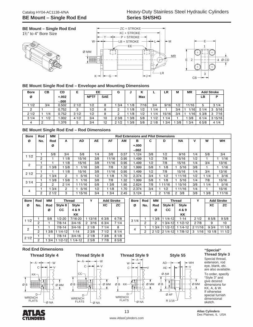
BE Mount – Single Rod End
BE Mount – Single Rod End 11/�" to 4" Bore Size
BE Mount Single Rod End – Envelope and Mounting Dimensions
BE Mount Single Rod End – Rod Dimensions
1
2
3
4
Ø MM
WEE
LB + STROKEP + STROKEY
XC + STROKEZC + STROKE
G J
L
K
E
E Ø CD
CB
M
LR
MR
NPTF SAE LB P
1 1/2 3/4 0.502 2 1/2 1/2 8 1 3/4 1 1/8 7/16 3/4 9/16 1/2 11/16 5 3 1/42 1 0.752 3 1/2 8 2 1 1/8 1/2 1 1/4 1 3/4 1 1/16 5 1/4 3 5/16
2 1/2 1 1/4 0.752 3 1/2 1/2 8 2 1 1/8 1/2 1 1/4 15/16 3/4 1 1/16 5 3/8 3 7/163 1/4 1 1/2 1.002 4 1/2 3/4 10 2 3/8 1 3/8 5/8 1 1/2 1 1/4 1 1 3/8 6 1/4 3 15/16
4 2 1.376 5 3/4 12 2 1/2 1 3/8 5/8 2 1/8 1 3/4 1 3/8 1 3/4 6 5/8 4 1/4
CD+.002-.000
CBBoreØ
J Add StrokeE KMax
L LREE G M MR
A AD AE AF AM B +.000-.002
C D NA V W WH
1 5/8 3/4 5/8 1/4 3/8 0.57 1.124 3/8 1/2 9/16 1/4 5/8 3/42 1 1 1/8 15/16 3/8 11/16 0.95 1.499 1/2 7/8 15/16 1/2 1 1 1/161 1 1 1/8 15/16 3/8 11/16 0.95 1.499 1/2 7/8 15/16 1/4 3/4 13/162 1 3/8 1 5/8 1 1/16 3/8 7/8 1.32 1.999 5/8 1 1/8 1 5/16 3/8 1 1 1/161 1 1 1/8 15/16 3/8 11/16 0.95 1.499 1/2 7/8 15/16 1/4 3/4 13/162 1 3/4 2 1 5/16 1/2 1 1/8 1.70 2.374 3/4 1 1/2 1 11/16 1/2 1 1/4 1 3/161 1 3/8 1 5/8 1 1/16 3/8 7/8 1.32 1.999 5/8 1 1/8 1 5/16 1/4 7/8 15/162 2 2 1/4 1 11/16 5/8 1 3/8 1.95 2.624 7/8 1 11/16 1 15/16 3/8 1 1/4 1 5/161 1 3/4 2 1 5/16 1/2 1 1/8 1.70 2.374 3/4 1 1/2 1 11/16 1/4 1 15/162 2 1/2 3 1 15/16 3/4 1 3/4 2.45 3.124 1 2 1/16 2 3/8 3/8 1 3/8 1 11/16
4
1 1/2
2
2 1/2
3 1/4
Rod Extensions and Pilot DimensionsMMRod
Ø
RodNo.
BoreØ
Style 8CC
Style4 & 9KK
XC ZC Style 8CC
Style4 & 9KK
XC ZC
1 5/8 1/2-20 7/16-20 1 13/16 6 3/8 6 7/8 1 1 3/8 1 1/4-12 1-14 2 1/2 8 5/8 9 5/82 1 7/8-14 3/4-16 2 3/16 6 3/4 7 1/4 2 2 1 3/4-12 1 1/2-12 2 7/8 9 101 1 7/8-14 3/4-16 2 1/8 7 1/4 8 1 1 3/4 1 1/2-12 1 1/4-12 2 11/16 9 3/4 11 1/82 1 3/8 1 1/4-12 1-14 2 3/8 7 1/2 8 1/4 2 2 1/2 2 1/4-12 1 7/8-12 3 1/16 10 1/8 11 1/21 1 7/8-14 3/4-16 2 1/8 7 3/8 8 1/82 1 3/4 1 1/2-12 1 1/4-12 2 5/8 7 7/8 8 5/8
1 1/2
2
2 1/2
Y Add StrokeBoreØ
RodNo.
MMRod
Ø
Thread
3 1/4
4
Y Add StrokeBoreØ
RodNo.
MMRod
Ø
Thread
Rod End Dimensions “Special” Thread Style 3Special thread, extension, rod eye, blank, etc. are also available. To order, specify “Style 3” and give desired dimensions for KK, A, & W. If otherwise special furnish dimensional sketch.
Thread Style 8 Thread Style 9Thread Style 4 Style 55
DWRENCH
FLATS
KK
Ø NA
A WC V
Ø B Ø MM
CC
V
Ø B
Ø NA
A W
C
Ø MM
DWRENCH
FLATS
KKØ B
WC
Ø NA
V
A
Ø MM
DWRENCH
FLATS R 1/16
Ø B
Ø AM
Ø AF
AE
AD WHV
Ø MM

Heavy-Duty Stainless Steel Hydraulic CylindersSeries SH/SHG
Catalog HY04-AC1138-4/NA
14 Atlas CylindersDes Plaines, IL USA
www.AtlasCylinders.com
F Mount – Single Rod End
F Mount Single Rod End – Envelope and Mounting Dimensions
F Mount Single Rod End – Rod Dimensions
F Mount – Single Rod End 11/�" to 4" Bore Size
1
2
3
4
TN
E
E
NT THREAD, ND DEEP4 TAPPED MTG. HOLES
Ø MM
W LB + STROKEEE
Y P + STROKEZB + STROKE
K
G
XT SN + STROKE
J
E2
- .005 - .010
NPTF SAE LB P SN1 1/2 2 1/2 1/2 8 1 3/4 1 1/8 7/16 3/8-16 3/4 5 3 1/4 2 7/8
2 3 1/2 8 2 1 1/8 1/2 1/2-13 15/16 5 1/4 3 5/16 2 7/82 1/2 3 1/2 1/2 8 2 1 1/8 1/2 5/8-11 1 5/16 5 3/8 3 7/16 33 1/4 4 1/2 3/4 10 2 3/8 1 3/8 5/8 3/4-10 1 1/2 6 1/4 3 15/16 3 1/2
4 5 3/4 12 2 1/2 1 3/8 5/8 1-8 2 1/16 6 5/8 4 1/4 4
Add StrokeEBoreØ
NTG TNEE J KMax
A AD AE AF AM B +.000-.002
C D NA V W WH
1 5/8 3/4 5/8 1/4 3/8 0.57 1.124 3/8 1/2 9/16 1/4 5/8 3/42 1 1 1/8 15/16 3/8 11/16 0.95 1.499 1/2 7/8 15/16 1/2 1 1 1/161 1 1 1/8 15/16 3/8 11/16 0.95 1.499 1/2 7/8 15/16 1/4 3/4 13/162 1 3/8 1 5/8 1 1/16 3/8 7/8 1.32 1.999 5/8 1 1/8 1 5/16 3/8 1 1 1/161 1 1 1/8 15/16 3/8 11/16 0.95 1.499 1/2 7/8 15/16 1/4 3/4 13/162 1 3/4 2 1 5/16 1/2 1 1/8 1.70 2.374 3/4 1 1/2 1 11/16 1/2 1 1/4 1 3/161 1 3/8 1 5/8 1 1/16 3/8 7/8 1.32 1.999 5/8 1 1/8 1 5/16 1/4 7/8 15/162 2 2 1/4 1 11/16 5/8 1 3/8 1.95 2.624 7/8 1 11/16 1 15/16 3/8 1 1/4 1 5/161 1 3/4 2 1 5/16 1/2 1 1/8 1.70 2.374 3/4 1 1/2 1 11/16 1/4 1 15/162 2 1/2 3 1 15/16 3/4 1 3/4 2.45 3.124 1 2 1/16 2 3/8 3/8 1 3/8 1 11/16
Rod Extensions and Pilot Dimensions
4
MMRod
Ø
RodNo.
BoreØ
1 1/2
2
2 1/2
3 1/4
AddStroke
AddStroke
Style 8CC
Style4 & 9KK
ZB Style 8CC
Style4 & 9KK
ZB
1 5/8 1/2-20 7/16-20 3/8 2 1 13/16 6 1/16 1 1 3/8 1 1/4-12 1-14 11/16 2 3/4 2 1/2 7 3/4 2 1 7/8-14 3/4-16 3/8 2 3/8 2 3/16 6 7/16 2 2 1 3/4-12 1 1/2-12 11/16 3 1/8 2 7/8 8 1/8 1 1 7/8-14 3/4-16 7/16 2 3/8 2 1/8 6 1/2 1 1 3/4 1 1/2-12 1 1/4-12 11/16 2 7/8 2 11/16 8 1/4 2 1 3/8 1 1/4-12 1-14 7/16 2 5/8 2 3/8 6 3/4 2 2 1/2 2 1/4-12 1 7/8-12 11/16 3 3/4 3 1/16 8 5/8 1 1 7/8-14 3/4-16 1/2 2 3/8 2 1/8 6 5/8 2 1 3/4 1 1/2-12 1 1/4-12 1/2 2 7/8 2 5/8 7 1/8
Y
1 1/2
2
2 1/2
BoreØ
RodNo.
MMRod
Ø
Thread ND XT
3 1/4
4
YBoreØ
RodNo.
MMRod
Ø
Thread ND XT
Rod End DimensionsThread Style 8 Thread Style 9Thread Style 4
“Special” Thread Style 3Special thread, extension, rod eye, blank, etc. are also available. To order, specify “Style 3” and give desired dimensions for KK, A, & W. If otherwise special furnish dimensional sketch.
Style 55
DWRENCH
FLATS
KK
Ø NA
A WC V
Ø B Ø MM
CC
V
Ø B
Ø NA
A W
C
Ø MM
DWRENCH
FLATS
KKØ B
WC
Ø NA
V
A
Ø MM
DWRENCH
FLATS R 1/16
Ø B
Ø AM
Ø AF
AE
AD WHV
Ø MM

Catalog HY04-AC1138-4/NA
15
Heavy-Duty Stainless Steel Hydraulic CylindersSeries SH/SHG
Atlas CylindersDes Plaines, IL USA
www.AtlasCylinders.com
F Mount – Double Rod End
F Mount – Double Rod End 11/�" to 4" Bore Size
F Mount Double Rod End – Envelope and Mounting Dimensions
F Mount Double Rod End – Rod Dimensions
1
2
3
4
E
E
TN
Ø MM
WY
EELD + STROKE
P + STROKEK
ZL + STROKEZM + 2 x STROKE
G G
XT SNK + STROKE
NT THREAD ND DEEP4 TAPPED MTG. HOLES
E2
- .005 - .010
NPTF SAE LD P SNK1 1/2 2 1/2 1/2 8 1 3/4 7/16 3/8-16 3/4 5 5/8 3 1/4 2 7/8
2 3 1/2 8 2 1/2 1/2-13 15/16 6 1/8 3 3/8 2 7/82 1/2 3 1/2 1/2 8 2 1/2 5/8-11 1 5/16 6 1/4 3 1/2 33 1/4 4 1/2 3/4 10 2 3/8 5/8 3/4-10 1 1/2 7 1/4 4 3 1/2
4 5 3/4 12 2 1/2 5/8 1-8 2 1/16 7 3/4 4 3/8 4
Add StrokeEBoreØ
NTG TNEE KMax
A AD AE AF AM B +.000-.002
C D NA V W WH
1 5/8 3/4 5/8 1/4 3/8 0.57 1.124 3/8 1/2 9/16 1/4 5/8 3/4 3/8 22 1 1 1/8 15/16 3/8 11/16 0.95 1.499 1/2 7/8 15/16 1/2 1 1 1/16 3/8 2 3/81 1 1 1/8 15/16 3/8 11/16 0.95 1.499 1/2 7/8 15/16 1/4 3/4 13/16 7/16 2 3/82 1 3/8 1 5/8 1 1/16 3/8 7/8 1.32 1.999 5/8 1 1/8 1 5/16 3/8 1 1 1/16 7/16 2 5/81 1 1 1/8 15/16 3/8 11/16 0.95 1.499 1/2 7/8 15/16 1/4 3/4 13/16 1/2 2 3/82 1 3/4 2 1 5/16 1/2 1 1/8 1.70 2.374 3/4 1 1/2 1 11/16 1/2 1 1/4 1 3/16 1/2 2 7/81 1 3/8 1 5/8 1 1/16 3/8 7/8 1.32 1.999 5/8 1 1/8 1 5/16 1/4 7/8 15/16 11/16 2 3/42 2 2 1/4 1 11/16 5/8 1 3/8 1.95 2.624 7/8 1 11/16 1 15/16 3/8 1 1/4 1 5/16 11/16 3 1/81 1 3/4 2 1 5/16 1/2 1 1/8 1.70 2.374 3/4 1 1/2 1 11/16 1/4 1 15/16 11/16 2 7/82 2 1/2 3 1 15/16 3/4 1 3/4 2.45 3.124 1 2 1/16 2 3/8 3/8 1 3/8 1 11/16 11/16 3 3/4
ND XTMMRod
Ø
RodNo.
BoreØ
Rod Extensions and Pilot Dimensions
4
1 1/2
2
2 1/2
3 1/4
AddStroke
Add 2XStroke
AddStroke
Add 2XStroke
Style 8CC
Style4 & 9KK
ZL ZM Style 8CC
Style4 & 9KK
ZL ZM
1 5/8 1/2-20 7/16-20 1 13/16 6 11/16 6 7/8 1 1 3/8 1 1/4-12 1-14 2 1/2 8 3/4 92 1 7/8-14 3/4-16 2 3/16 7 1/16 7 5/8 2 2 1 3/4-12 1 1/2-12 2 7/8 9 1/8 9 3/41 1 7/8-14 3/4-16 2 1/8 7 3/8 7 5/8 1 1 3/4 1 1/2-12 1 1/4-12 2 11/16 9 3/8 9 3/42 1 3/8 1 1/4-12 1-14 2 3/8 7 5/8 8 1/8 2 2 1/2 2 1/4-12 1 7/8-12 3 1/16 9 3/4 10 1/21 1 7/8-14 3/4-16 2 1/8 7 1/2 7 3/42 1 3/4 1 1/2-12 1 1/4-12 2 5/8 8 8 3/4
Y
3 1/4
4
YBoreØ
RodNo.
MMRod
Ø
Thread
1 1/2
2
2 1/2
ThreadBoreØ
RodNo.
MMRod
Ø
Rod End Dimensions “Special” Thread Style 3Special thread, extension, rod eye, blank, etc. are also available. To order, specify “Style 3” and give desired dimensions for KK, A, & W. If otherwise special furnish dimensional sketch.
Thread Style 8 Thread Style 9Thread Style 4 Style 55
DWRENCH
FLATS
KK
Ø NA
A WC V
Ø B Ø MM
CC
V
Ø B
Ø NA
A W
C
Ø MM
DWRENCH
FLATS
KKØ B
WC
Ø NA
V
A
Ø MM
DWRENCH
FLATS R 1/16
Ø B
Ø AM
Ø AF
AE
AD WHV
Ø MM

Heavy-Duty Stainless Steel Hydraulic CylindersSeries SH/SHG
Catalog HY04-AC1138-4/NA
16 Atlas CylindersDes Plaines, IL USA
www.AtlasCylinders.com
D Mount – Single Rod End
D Mount Single Rod End – Envelope and Mounting Dimensions
D Mount Single Rod End – Rod Dimensions
D Mount – Single Rod End 11/�" to 4" Bore Size
1
2
3
4
E
E
TLUT
TL
Ø MM
WDEE
LB + STROKEYD P + STROKE
ZS + STROKE
G
XGJ
K
Ø TD
NPTF SAE LB P
1 1/2 2 1/2 1/2 8 1 3/4 1 1/8 7/16 1.000 1 4 1/2 5 3 1/42 3 1/2 8 2 1 1/8 1/2 1.375 1 3/8 5 3/4 5 1/4 3 5/16
2 1/2 3 1/2 1/2 8 2 1 1/8 1/2 1.375 1 3/8 6 1/4 5 3/8 3 7/163 1/4 4 1/2 3/4 10 2 3/8 1 3/8 5/8 1.750 1 3/4 8 6 1/4 3 15/16
4 5 3/4 12 2 1/2 1 3/8 5/8 1.750 1 3/4 8 1/2 6 5/8 4 1/4
EBoreØ
TD+.000-.001
Add StrokeUTG TLEE J K Max
A AD AE AF AM B +.000-.002
C D NA V WD WJ
1 5/8 3/4 5/8 1/4 3/8 0.57 1.124 3/8 1/2 9/16 1/4 1 1 1/82 1 1 1/8 15/16 3/8 11/16 0.95 1.499 1/2 7/8 15/16 1/2 1 3/8 1 7/161 1 1 1/8 15/16 3/8 11/16 0.95 1.499 1/2 7/8 15/16 1/4 1 1/4 1 5/162 1 3/8 1 5/8 1 1/16 3/8 7/8 1.32 1.999 5/8 1 1/8 1 5/16 3/8 1 1/2 1 9/161 1 1 1/8 15/16 3/8 11/16 0.95 1.499 1/2 7/8 15/16 1/4 1 1/4 1 5/162 1 3/4 2 1 5/16 1/2 1 1/8 1.70 2.374 3/4 1 1/2 1 11/16 1/2 1 3/4 1 11/161 1 3/8 1 5/8 1 1/16 3/8 7/8 1.32 1.999 5/8 1 1/8 1 5/16 1/4 1 7/16 1 1/22 2 2 1/4 1 11/16 5/8 1 3/8 1.95 2.624 7/8 1 11/16 1 15/16 3/8 1 13/16 1 7/81 1 3/4 2 1 5/16 1/2 1 1/8 1.70 2.374 3/4 1 1/2 1 11/16 1/4 1 5/8 1 9/162 2 1/2 3 1 15/16 3/4 1 3/4 2.45 3.124 1 2 1/16 2 3/8 3/8 2 2 5/16
4
BoreØ
1 1/2
2
2 1/2
Rod Extensions and Pilot DimensionsMMRod
Ø
RodNo.
3 1/4
Add Stroke Add StrokeStyle 8
CCStyle4 & 9KK
ZS Style 8CC
Style4 & 9KK
ZS
1 5/8 1/2-20 7/16-20 1 7/8 2 3/16 6 7/16 1 1 3/8 1 1/4-12 1-14 2 5/8 3 1/16 8 5/162 1 7/8-14 3/4-16 2 1/4 2 9/16 6 13/16 2 2 1 3/4-12 1 1/2-12 3 3 7/16 8 11/161 1 7/8-14 3/4-16 2 1/4 2 5/8 7 1 1 3/4 1 1/2-12 1 1/4-12 2 7/8 3 5/16 8 7/82 1 3/8 1 1/4-12 1-14 2 1/2 2 7/8 7 1/4 2 2 1/2 2 1/4-12 1 7/8-12 3 1/4 3 11/16 9 1/41 1 7/8-14 3/4-16 2 1/4 2 5/8 7 1/82 1 3/4 1 1/2-12 1 1/4-12 2 3/4 3 1/8 7 5/8
3 1/4
4
XG YDBoreØ
RodNo.
MMRod
Ø
ThreadThread XG YD
1 1/2
MMRod
Ø
2
2 1/2
BoreØ
RodNo.
Rod End DimensionsThread Style 8 Thread Style 9Thread Style 4
“Special” Thread Style 3Special thread, extension, rod eye, blank, etc. are also available. To order, specify “Style 3” and give desired dimensions for KK, A, & WD. If otherwise special furnish dimensional sketch.
Style 55
DWRENCH
FLATS
KK
Ø NA
A WD
CV
Ø B Ø MM
V
Ø B
Ø NA
A WD
C
Ø MM
DWRENCH
FLATS
CC
KKØ B
WD
C
Ø NA
A
Ø MM
DWRENCH
FLATS
V
R 1/16
Ø B
Ø AM
Ø AF
AE
AD WJ
Ø MM
V

Catalog HY04-AC1138-4/NA
17
Heavy-Duty Stainless Steel Hydraulic CylindersSeries SH/SHG
Atlas CylindersDes Plaines, IL USA
www.AtlasCylinders.com
D Mount – Double Rod End
D Mount – Double Rod End 11/�" to 4" Bore Size
D Mount Double Rod End – Envelope and Mounting Dimensions
D Mount Double Rod End – Rod Dimensions
1
2
3
4
E
E
Ø TD
TL TLUT XG
G
Ø MM
WDEE
LD + STROKEYD P + STROKE
ZT + STROKEZW + 2 x STROKE
G
K
NPTF SAE LD P
1 1/2 2 1/2 1/2 8 1 3/4 7/16 1.000 1 4 1/2 5 5/8 3 1/42 3 1/2 8 2 1/2 1.375 1 3/8 5 3/4 6 1/8 3 3/8
2 1/2 3 1/2 1/2 8 2 1/2 1.375 1 3/8 6 1/4 6 1/4 3 1/23 1/4 4 1/2 3/4 10 2 3/8 5/8 1.750 1 3/4 8 7 1/4 4
4 5 3/4 12 2 1/2 5/8 1.750 1 3/4 8 1/2 7 3/4 4 3/8
BoreØ
TLE G Add StrokeUTEE MaxK
TD+.000-.001
A AD AE AF AM B +.000-.002
C D NA V WD WJ
1 5/8 3/4 5/8 1/4 3/8 0.57 1.124 3/8 1/2 9/16 1/4 1 1 1/8 1 7/8 2 3/162 1 1 1/8 15/16 3/8 11/16 0.95 1.499 1/2 7/8 15/16 1/2 1 3/8 1 7/16 2 1/4 2 9/161 1 1 1/8 15/16 3/8 11/16 0.95 1.499 1/2 7/8 15/16 1/4 1 1/4 1 5/16 2 1/4 2 5/82 1 3/8 1 5/8 1 1/16 3/8 7/8 1.32 1.999 5/8 1 1/8 1 5/16 3/8 1 1/2 1 9/16 2 1/2 2 7/81 1 1 1/8 15/16 3/8 11/16 0.95 1.499 1/2 7/8 15/16 1/4 1 1/4 1 5/16 2 1/4 2 5/82 1 3/4 2 1 5/16 1/2 1 1/8 1.70 2.374 3/4 1 1/2 1 11/16 1/2 1 3/4 1 11/16 2 3/4 3 1/81 1 3/8 1 5/8 1 1/16 3/8 7/8 1.32 1.999 5/8 1 1/8 1 5/16 1/4 1 7/16 1 1/2 2 5/8 3 1/162 2 2 1/4 1 11/16 5/8 1 3/8 1.95 2.624 7/8 1 11/16 1 15/16 3/8 1 13/16 1 7/8 3 3 7/161 1 3/4 2 1 5/16 1/2 1 1/8 1.70 2.374 3/4 1 1/2 1 11/16 1/4 1 5/8 1 9/16 2 7/8 3 5/162 2 1/2 3 1 15/16 3/4 1 3/4 2.45 3.124 1 2 1/16 2 3/8 3/8 2 2 5/16 3 1/4 3 11/16
YDRod Extensions and Pilot DimensionsMMRod
Ø
RodNo.
XGBoreØ
4
1 1/2
2
2 1/2
3 1/4
Add Stroke Add 2X Stroke Add Stroke Add 2X StrokeStyle 8
CCStyle4 & 9KK
ZT ZW Style 8CC
Style4 & 9KK
ZT ZW
1 5/8 1/2-20 7/16-20 7 1/16 7 1/4 1 1 3/8 1 1/4-12 1-14 9 5/16 9 9/162 1 7/8-14 3/4-16 7 7/16 8 2 2 1 3/4-12 1 1/2-12 9 11/16 10 5/161 1 7/8-14 3/4-16 7 7/8 8 1/8 1 1 3/4 1 1/2-12 1 1/4-12 10 10 3/82 1 3/8 1 1/4-12 1-14 8 1/8 8 5/8 2 2 1/2 2 1/4-12 1 7/8-12 10 3/8 11 1/81 1 7/8-14 3/4-16 8 8 1/42 1 3/4 1 1/2-12 1 1/4-12 8 1/2 9 1/4
2 1/2
Thread
3 1/4
4
BoreØ
RodNo.
MMRod
Ø
Thread
2
1 1/2
BoreØ
RodNo.
MMRod
Ø
Rod End DimensionsThread Style 8 Thread Style 9Thread Style 4
“Special” Thread Style 3Special thread, extension, rod eye, blank, etc. are also available. To order, specify “Style 3” and give desired dimensions for KK, A, & WD. If otherwise special furnish dimensional sketch.
Style 55
DWRENCH
FLATS
KK
Ø NA
A WD
CV
Ø B Ø MM
V
Ø B
Ø NA
A WD
C
Ø MM
DWRENCH
FLATS
CC
KKØ B
WD
C
Ø NA
A
Ø MM
DWRENCH
FLATS
V
R 1/16
Ø B
Ø AM
Ø AF
AE
AD WJ
Ø MM
V

Heavy-Duty Stainless Steel Hydraulic CylindersSeries SH/SHG
Catalog HY04-AC1138-4/NA
18 Atlas CylindersDes Plaines, IL USA
www.AtlasCylinders.com
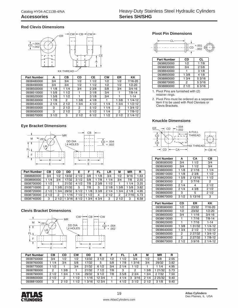
Cylinder AccessoriesType 316 Stainless Steel mounting accessories are offered to provide you a complete corrosion resistant cylinder mounting package. A Clevis Bracket and (17-4 SS) Pivot Pin are available for Mounting Style BE. Select the Clevis Bracket and Pin in the row to the right of the bore size cylinder required.
Rod End AccessoriesAccessories offered for the rod end of the cylinder include Rod Clevis, Knuckle, Eye Bracket, Clevis Bracket and (17-4 SS) Pivot Pin. To select the proper part number for any desired accessory, refer to the table below or on the opposite page and look in the row to the right of the rod thread in the first column. For economical accessory selection, it is recommended that rod end style 4 be specified on your cylinder order.
Accessory Load CapacityThe various accessories have been load rated for your convenience. The load capacity in lbs. is the recommended maximum load for that accessory based on a 4:1 design factor in tension. (Pivot pin is rated in shear). Before specifying, compare the actual load or the tension (pull) force at maximum operating pressure of the cylinder with the load capacity of the accessory you plan to use. If the load or pull force of the cylinder exceeds the accessory capacity, consult the factory.
All Accessories Include Electropolishing
Rod End Accessories
7/16-20 0938480000 2125 0938680000 2050 0938820000 80001/2-20 0938490000 2450 0938680000 2050 0938820000 80003/4-16 0938500000 5600 0938690000 5800 0938830000 179007/8-14 0938510000 9400 0938700000 12200 0938840000 319001-14 0938520000 9750 0938700000 12200 0938840000 31900
1 1/4-12 0938530000 22300 0938710000 12720 0938850000 605001 1/2-12 0938540000 30400 0938720000 32900 0938860000 980001 3/4-12 0938550000 43700 0938730000 46600 0938870000 1277001 7/8-12 0938560000 43700 0938730000 46600 0938870000 1277002 1/4-12 0938570000 65400 0938740000 62800 0938880000 199600
ThreadSize Part Number
Load Capacity(Lbs.)
Rod Clevis Eye Bracket
Part NumberLoad Capacity
(Lbs.)
Pivot Pin
Part NumberLoad Capacity
(Lbs.)
Cylinder Accessories
1 1/2 0938750000 3650 0938820000 80002, 2 1/2 0938760000 7000 0938830000 179003 1/4 0938770000 9600 0938840000 31900
4 0938780000 20120 0938850000 60500
BoreØ
Clevis Bracket Pivot Pin
Part NumberLoad Capacity
(Lbs.)Part Number
Load Capacity(Lbs.)
Accessories
Rod End Accessories
7/16-20 0938580000 2700 0938750000 3650 0938820000 80001/2-20 0938590000 3100 0938750000 3650 0938820000 80003/4-16 0938600000 7200 0938760000 7000 0938830000 179007/8-14 0938610000 7800 0938770000 9600 0938840000 319001-14 0938620000 13000 0938770000 9600 0938840000 31900
1 1/4-12 0938630000 20000 0938780000 20120 0938850000 605001 1/2-12 0938640000 30000 0938790000 20300 0938860000 980001 3/4-12 0938650000 35500 0938800000 19700 0938870000 1277001 7/8-12 0938660000 50000 0938800000 19700 0938870000 1277002 1/4-12 0938670000 65000 0938810000 20900 0938880000 199600
ThreadSize
Knuckle Clevis Bracket Pivot Pin
Part NumberLoad Capacity
(Lbs.)Part Number
Load Capacity(Lbs.)
Part NumberLoad Capacity
(Lbs.)
Catalog HY04-AC1138-4/NA
19
Heavy-Duty Stainless Steel Hydraulic CylindersSeries SH/SHG
Atlas CylindersDes Plaines, IL USA
www.AtlasCylinders.com
Accessories
Rod Clevis Dimensions
CBCW CWER
KK THREAD
+.004+.002CD
A
CE
Pivot Pin Dimensions
CL
CD +.001 -.002
Part Number CD CL0938820000 1/2 1 7/80938830000 3/4 2 5/80938840000 1 3 1/80938850000 1 3/8 4 1/80938860000 1 3/4 5 3/160938870000 2 5 3/160938880000 2 1/2 6 3/16
Eye Bracket Dimensions
MR
LR
RE
DD DIA4 HOLES
F
M 25°
FL
CB
+ .004+ .002
RE
CD
Part Number CB CD DD E F FL LR M MR R0968680000 3/4 1/2 13/32 2 1/2 3/8 1 1/8 3/4 1/2 9/16 1.630938690000 1 1/4 3/4 17/32 3 1/2 5/8 1 7/8 1 1/4 3/4 7/8 2.550938700000 1 1/2 1 21/32 4 1/2 7/8 2 3/8 1 1/2 1 1 1/4 3.250938710000 2 1 3/8 21/32 5 7/8 3 2 1/8 1 3/8 1 5/8 3.820938720000 2 1/2 1 3/4 29/32 6 1/2 1 1/8 3 3/8 2 1/4 1 3/4 2 1/8 4.950938730000 2 1/2 2 1 1/16 7 1/2 1 1/2 4 2 1/2 2 2 7/16 5.730938740000 3 2 1/2 1 3/16 8 1/2 1 3/4 4 3/4 3 2 1/2 3 6.58
Clevis Bracket Dimensions
25°MR
LR
RE
DD DIA4 HOLES
F
M
FL
CW CWCB
+ .004+ .002
RE
CD
Part Number CB CD CW DD E F FL LR M MR R0938750000 3/4 1/2 1/2 13/32 3 1/2 1/2 1 1/2 3/4 1/2 5/8 2.550938760000 1 1/4 3/4 5/8 17/32 5 5/8 1 7/8 1 3/16 3/4 29/32 3.820938770000 1 1/2 1 3/4 21/32 6 1/2 3/4 2 1/4 1 1/2 1 1 1/4 4.950938780000 2 1 3/8 1 21/32 7 1/2 7/8 3 2 1 3/8 1 21/32 5.730938790000 2 1/2 1 3/4 1 1/4 29/32 9 1/2 7/8 3 5/8 2 3/4 1 3/4 2 7/32 7.500938800000 2 1/2 2 1 1/2 1 1/16 12 3/4 1 4 1/4 3 3/16 2 1/4 2 25/32 9.400938810000 3 2 1/2 1 1/2 1 3/16 12 3/4 1 4 1/2 3 1/2 2 1/2 3 1/8 9.40
1. Pivot Pins are furnished with (2) retainer rings.�. Pivot Pins must be ordered as a separate item if to be used with Rod Clevises or Clevis Brackets.
Part Number A CB CD CE CW ER KK0938480000 3/4 3/4 1/2 1 1/2 1/2 1/2 7/16-200938490000 3/4 3/4 1/2 1 1/2 1/2 1/2 1/2-200938500000 1 1/8 1 1/4 3/4 2 3/8 5/8 3/4 3/4-160938510000 1 5/8 1 1/2 1 3 1/8 3/4 1 7/8-140938520000 1 5/8 1 1/2 1 3 1/8 3/4 1 1-140938530000 1 7/8 2 1 3/8 4 1/8 1 1 3/8 1 1/4-120938540000 2 1/4 2 1/2 1 3/4 4 1/2 1 1/4 1 3/4 1 1/2-120938550000 3 2 1/2 2 5 1/2 1 1/4 2 1 3/4-120938560000 3 2 1/2 2 5 1/2 1 1/4 2 1 7/8-120938570000 3 1/2 3 2 1/2 6 1/2 1 1/2 2 1/2 2 1/4-12
Knuckle Dimensions
CB
CDER +.004+.002
CD CA
CD
CDKK THREAD
A FULLTHREAD
Part Number A CA CB0938580000 3/4 1 1/2 3/40938590000 3/4 1 1/2 3/40938600000 1 1/8 2 1/16 1 1/40938610000 1 1/8 2 3/8 1 1/20938620000 1 5/8 2 13/16 1 1/20938630000 2 3 7/16 20938640000 2 1/4 4 2 1/20938650000 2 1/4 4 3/8 2 1/20938660000 3 5 2 1/20938670000 3 1/2 5 13/16 3
Part Number CD ER KK0938580000 1/2 23/32 7/16-200938590000 1/2 23/32 1/2-200938600000 3/4 1 1/16 3/4-160938610000 1 1 7/16 7/8-140938620000 1 1 7/16 1-140938630000 1 3/8 1 31/32 1 1/4-120938640000 1 3/4 2 1/2 1 1/2-120938650000 2 2 27/32 1 3/4-120938660000 2 2 27/32 1 7/8-120938670000 2 1/2 3 9/16 2 1/4-12

Heavy-Duty Stainless Steel Hydraulic CylindersSeries SH/SHG
Catalog HY04-AC1138-4/NA
�0 Atlas CylindersDes Plaines, IL USA
www.AtlasCylinders.com
Stop Tubing / Mounting Classes
FIXED MOUNTS which do not absorb force on the centerline.
For Thrust Loads Mtg. Style FFor Tension Loads Mtg. Style F
Heavy-Duty ServiceFor Thrust Loads Mtg. Style DFor Tension Loads Mtg. Styles BE, D
Group 3
Mounting ClassesStandard mountings for fluid power cylinders fall into three basic groups. The groups can be summarized as follows:Group 1 – Straight Line Force Transfer with fixed mounts which absorb force on cylinder centerline.Group 2 – Pivot Force Transfer. Pivot mountings permit a cylinder to change its alignment in one plane.Group 3 – Straight Line Force Transfer with fixed mounts which do not absorb force on cylinder centerline.Because a cylinder’s mounting directly affects the maximum pressure at which the cylinder can be used, the chart below should be helpful in selection of the proper mounting combination for your application. Stroke length, piston rod connection to load, extra piston rod length over standard, etc., should be considered for thrust loads. Alloy steel mounting bolts are recommended for all mounting styles, and thrust keys are recommended for Group 3.
Group 1 FIXED MOUNTS which absorb force on cylinder centerline.
For Thrust Loads Mtg. Styles HH, TCFor Tension Loads Mtg. Styles JJ, TB
Group 2 PIVOT MOUNTS which absorb force on cylinder centerline.
Stop TubingStop tube is recommended to lengthen the distance between the gland and piston to reduce bearing loads when the cylinder is fully extended. This is especially true of horizontally mounted and long stroke cylinders. Long stroke cylinders achieve additional stability through the use of a stop tube.
Drawing A
When specifying cylinders with long stroke and stop tube, be sure to call out the net stroke and the length of the stop tube. Machine design can be continued without delay by laying in a cylinder equivalent in length to the NET STROKE PLUS STOP TUBE LENGTH, which is referred to as GROSS STROKE.Refer to piston rod/stroke selection chart to determine stop tube length.
Drawing B
This design is supplied on all non cushion cylinders.
(HEAD END) PISTON ROD STOP TUBE (CAP END)PISTON
GROSS STROKE
NET STROKE STOPTUBELENGTH
LB + GROSS STROKE
(HEAD END) PISTON ROD STOP TUBE (CAP END)PISTON
GROSS STROKE
NET STROKE STOPTUBELENGTH
LB + GROSS STROKE

Catalog HY04-AC1138-4/NA
�1
Heavy-Duty Stainless Steel Hydraulic CylindersSeries SH/SHG
Atlas CylindersDes Plaines, IL USA
www.AtlasCylinders.com
Cylinder Stroke Chart
Recommended Mounting Styles for Rod End StrokeMaximum Stroke and Thrust Loads Connection Case Factor
Fixed and RigidlyGuided
Pivoted and RigidlyGuided
Supported but not Rigidly Guided
Pivoted and Rigidly Guided
Pivoted and Rigidly Guided
.50
.70
�.00
1.00
�.00
100 2 3 4 5 6 7 8 9 1000 2 3 4 5 6 7 8 9 10,000 2 3 4 5 6 7 8 9 100,000 2 310
20
30
40
50
60
300
200
100908070
THRUST–POUNDS
ROD DIAMETER
BA
SIC
LE
NG
TH–I
NC
HE
S
INC
HE
S O
F
STO
P T
UB
E
1
2
34567
CO
NS
ULT
FA
CTO
RY
58
1
134 2 21
2381
I
II
III
IV
V
How to Use the ChartThe selection of a piston rod for thrust (push) conditions requires the following steps:1. Determine the type of cylinder mounting style and rod end
connection to be used. Then consult the chart below and find the “stroke factor” that corresponds to the conditions used.
2. Using this stroke factor, determine the “basic length” from the equation:
The graph is prepared for standard rod extensions beyond the face of the head. For rod extensions greater than standard, add the increase to the stroke in arriving at the “basic length.”
3. Find the load imposed for the thrust application by multiplying the full bore area of the cylinder by the system pressure.
4. Enter the graph along the values of “basic length” and “thrust” as found above and note the point of intersection:
A) The correct piston rod size is read from the diagonally curved line labeled “Rod Diameter” next above the point of intersection.
B) The required length of stop tube is read from the right of the graph by following the shaded band in which the point of intersection lies.
C) If required length of stop tube is in the region labeled “consult factory,” submit the following information for an individual analysis:
1) Cylinder mounting style.2) Rod end connection and method of guiding load.3) Bore, required stroke, length of rod extension (Dim. “A” and “W”) if
greater than standard, and series of cylinder used.4) Mounting position of cylinder. (Note: If at an angle or vertical,
specify direction of piston rod.)5) Operating pressure of cylinder if limited to less than standard
pressure for cylinder selected.
WarningPiston rods are not normally designed to absorb bending moments or loads which are perpendicular to the axis of piston rod motion. These additional loads can cause the piston rod end to fail. If these types of additional loads are expected to be imposed on the piston rods, their magnitude should be made known to our Engineering Department so they may be properly addressed. Additionally, cylinder users should always make sure that the piston rod is securely attached to the machine member.
Basic = Actual x Stroke Length Stroke Factor
Piston Rod — Stroke Selection Chart
Groups 1 or 3Long stroke cylinders for thrust loads should be firmly fixed at one end and aligned to take the principal force. Additional mounting should be specified at the opposite end, which should be used for alignment and support. An intermediate support may also be desirable for long stroke cylinders mounted horizontally. Machine mounting pads can be adjustable for support mountings to achieve proper alignment.
Group 2Style D — Trunnion on Head
Style BE — Eye on Cap

Heavy-Duty Stainless Steel Hydraulic CylindersSeries SH/SHG
Catalog HY04-AC1138-4/NA
�� Atlas CylindersDes Plaines, IL USA
www.AtlasCylinders.com
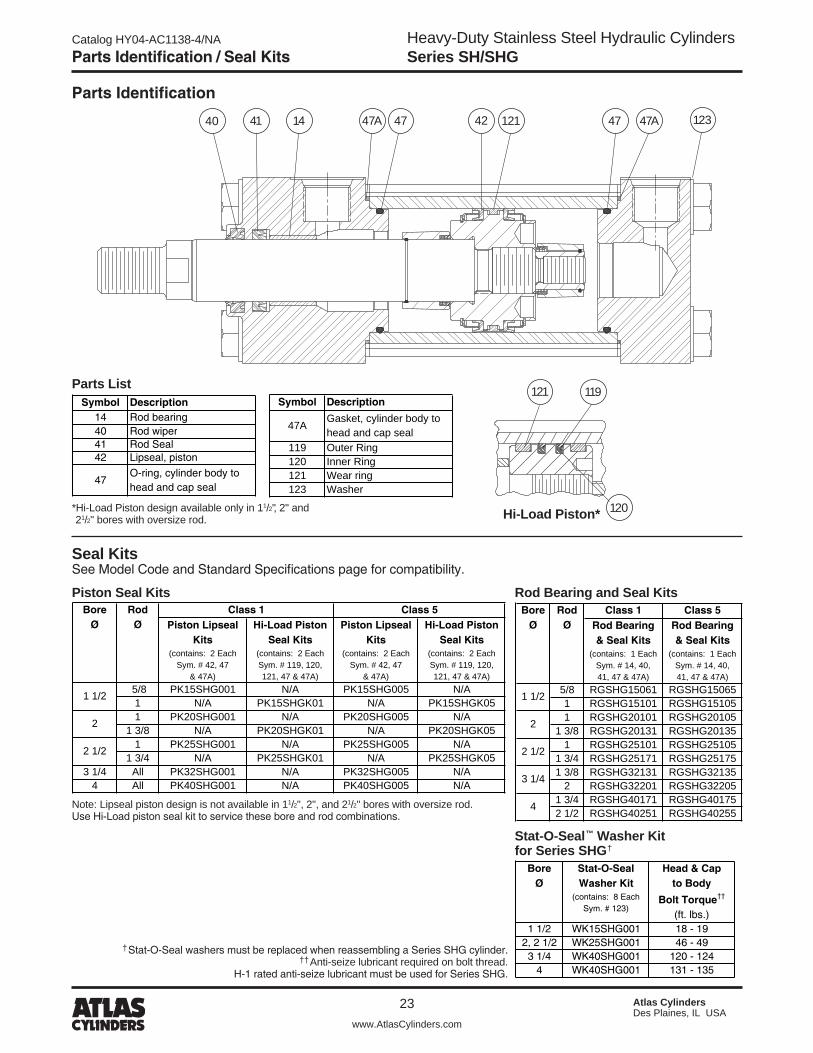
Parts List / Thrust Key Mounting
Parts List
Thrust Key Mounting In addition to mounting bolts, Style F cylinders should be keyed to the mounting surface with a thrust key.
PA FA TA
Piston and Rod Assemblies Factory assembled piston and rod assemblies (that include seals for the piston type specified) are recommended.
Symbol Description1 Head7 Cap15 Cylinder Body17 Piston, lipseal type18 Cushion sleeve, head end cushion
18A Cushion check spring, head end cushion18B Cushion retaining wire, head end cushion23 Bolt, head and cap to body37 Piston rod, single rod type42 Lipseal, piston44 Anti-roll ring, piston lipseal46 Retaining ring, piston lipseal47 O-ring, cylinder body to head and cap seal118 Piston, Hi-Load type*119 Outer ring120 Inner ring121 Wear ring123 Washer137 Cushion sleeve, cap end cushion
137A Cushion check spring, cap end cushion137B Cushion retaining wire, cap end cushion137C Cushion support, cap end cushion
An optional groove can be supplied in the head for installing a thrust key.
121 119
118
120Hi-Load Piston*
*Hi-Load Piston design available only in 11/�", �" and �1/�" bores with oversize rod.
Parts List
Bore
+.001-.000FA PA TA
1 1/2 0.312 5/32 5/82 0.375 3/16 3/4
2 1/2 0.375 3/16 3/43 1/4 0.500 1/4 7/8
4 0.500 1/4 7/8
123 123 47 18B 18 18A 42 44 46 47
37 15 137B137A 137 137C
7
17
Catalog HY04-AC1138-4/NA
�3
Heavy-Duty Stainless Steel Hydraulic CylindersSeries SH/SHG
Atlas CylindersDes Plaines, IL USA
www.AtlasCylinders.com
Parts Identification / Seal Kits
Seal Kits See Model Code and Standard Specifications page for compatibility.
Piston Seal Kits Rod Bearing and Seal Kits
121
120
119
Parts Identification
Hi-Load Piston**Hi-Load Piston design available only in 11/�", �" and �1/�" bores with oversize rod.
5/8 PK15SHG001 N/A PK15SHG005 N/A1 N/A PK15SHGK01 N/A PK15SHGK051 PK20SHG001 N/A PK20SHG005 N/A
1 3/8 N/A PK20SHGK01 N/A PK20SHGK051 PK25SHG001 N/A PK25SHG005 N/A
1 3/4 N/A PK25SHGK01 N/A PK25SHGK053 1/4 All PK32SHG001 N/A PK32SHG005 N/A
4 All PK40SHG001 N/A PK40SHG005 N/A
Hi-Load PistonSeal Kits
(contains: 2 Each Sym. # 119, 120,121, 47 & 47A)
BoreØ
Class 1RodØ
2
2 1/2
Class 5Piston Lipseal
Kits(contains: 2 Each
Sym. # 42, 47& 47A)
Hi-Load PistonSeal Kits
(contains: 2 Each Sym. # 119, 120,121, 47 & 47A)
1 1/2
Piston LipsealKits
(contains: 2 Each Sym. # 42, 47
& 47A)
Note: Lipseal piston design is not available in 11/�", �", and �1/�" bores with oversize rod. Use Hi-Load piston seal kit to service these bore and rod combinations.
1 1/2 WK15SHG001 18 - 192, 2 1/2 WK25SHG001 46 - 493 1/4 WK40SHG001 120 - 124
4 WK40SHG001 131 - 135
BoreØ
Stat-O-SealWasher Kit
(contains: 8 Each Sym. # 123)
Head & Capto Body
Bolt Torque††
(ft. lbs.)
Stat-O-Seal™ Washer Kit for Series SHG†
†Stat-O-Seal washers must be replaced when reassembling a Series SHG cylinder.††Anti-seize lubricant required on bolt thread.
H-1 rated anti-seize lubricant must be used for Series SHG.
Class 1 Class 5
5/8 RGSHG15061 RGSHG150651 RGSHG15101 RGSHG151051 RGSHG20101 RGSHG20105
1 3/8 RGSHG20131 RGSHG201351 RGSHG25101 RGSHG25105
1 3/4 RGSHG25171 RGSHG251751 3/8 RGSHG32131 RGSHG32135
2 RGSHG32201 RGSHG322051 3/4 RGSHG40171 RGSHG401752 1/2 RGSHG40251 RGSHG40255
3 1/4
4
RodØ
1 1/2
2
2 1/2
Rod Bearing& Seal Kits
(contains: 1 Each Sym. # 14, 40,41, 47 & 47A)
BoreØ Rod Bearing
& Seal Kits(contains: 1 Each
Sym. # 14, 40,41, 47 & 47A)
4140 47A 42 121 47 47A14 47 123
Symbol Description14 Rod bearing40 Rod wiper41 Rod Seal42 Lipseal, piston
47O-ring, cylinder body tohead and cap seal
Parts ListSymbol Description
47AGasket, cylinder body to head and cap seal
119 Outer Ring120 Inner Ring121 Wear ring123 Washer

Heavy-Duty Stainless Steel Hydraulic CylindersSeries SH/SHG
Catalog HY04-AC1138-4/NA
�4 Atlas CylindersDes Plaines, IL USA
www.AtlasCylinders.com
Cylinder Safety Guide
Before selecting or using Atlas (The Company) cylinders or related accessories, it is important that you read, understand and follow the following safety information. Training is advised before selecting and using The Company’s products.
1.0 General Instructions 1.1 Scope – This safety guide provides instructions for selecting and using
(including assembling, installing, and maintaining) cylinder products. This safety guide is a supplement to and is to be used with the specific Company publications for the specific cylinder products that are being considered for use.
1.2 Fail Safe – Cylinder products can and do fail without warning for many reasons. All systems and equipment should be designed in a fail-safe mode so that if the failure of a cylinder product occurs people and property won’t be endangered.
1.3 Distribution – Provide a free copy of this safety guide to each person responsible for selecting or using cylinder products. Do not select or use The Company’s cylinders without thoroughly reading and understanding this safety guide as well as the specific Company publications for the products considered or selected.
1.4 User Responsibility – Due to very wide variety of cylinder applications and cylinder operating conditions, The Company does not warrant that any particular cylinder is suitable for any specific application. This safety guide does not analyze all technical parameters that must be considered in select-ing a product. The hydraulic and pneumatic cylinders outlined in this catalog are designed to The Company’s design guidelines and do not necessarily meet the design guideline of other agencies such as American Bureau of Shipping, ASME Pressure Vessel Code etc. The user, through its own analysis and testing, is solely responsible for:
• Making the final selection of the cylinders and related accessories. • Determining if the cylinders are required to meet specific design require-
ments as required by the Agency(s) or industry standards covering the design of the user’s equipment.
• Assuring that the user’s requirements are met, OSHA requirements are met, and safety guidelines from the applicable agencies such as but not limited to ANSI are followed and that the use presents no health or safety hazards.
• Providing all appropriate health and safety warnings on the equipment on which the cylinders are used.
1.5 Additional Questions – Call the appropriate Company technical service department if you have any questions or require any additional information. See the Company publication for the product being considered or used, or call the number on the back cover of this catalog for the technical service department.
2.0 Cylinder and Accessories Selection 2.1 Seals – Part of the process of selecting a cylinder is the selection of
seal compounds. Before making this selection, consult the “seal information page(s)” of the publication for the series of cylinders of interest.
The application of cylinders may allow fluids such as cutting fluids, wash down fluids etc. to come in contact with the external area of the cylinder. These fluids may attack the piston rod wiper and or the primary seal and must be taken into account when selecting and specifying seal compounds.
Dynamic seals will wear. The rate of wear will depend on many operating factors. Wear can be rapid if a cylinder is mis-aligned or if the cylinder has been improperly serviced. The user must take seal wear into consideration in the application of cylinders.
2.2 Piston Rods – Possible consequences of piston rod failure or separation of the piston rod from the piston include, but are not limited to are:
• Piston rod and or attached load thrown off at high speed. • High velocity fluid discharge. • Piston rod extending when pressure is applied in the piston
retract mode.
Piston rods or machine members attached to the piston rod may move suddenly and without warning as a consequence of other conditions occurring to the machine such as, but not limited to:
• Unexpected detachment of the machine member from the piston rod.
• Failure of the pressurized fluid delivery system (hoses, fittings, valves, pumps, compressors) which maintain cylinder position.
• Catastrophic cylinder seal failure leading to sudden loss of pressurized fluid.
• Failure of the machine control system. Follow the recommendations of the “Piston Rod Selection Chart and Data”
in the publication for the series of cylinders of interest. The suggested piston rod diameter in these charts must be followed in order to avoid piston rod buckling.
Piston rods are not normally designed to absorb bending moments or loads which are perpendicular to the axis of piston rod motion. These additional loads can cause the piston rod to fail. If these types of additional loads are expected to be imposed on the piston rod, their magnitude should be made known to our engineering department.
The cylinder user should always make sure that the piston rod is securely attached to the machine member.
On occasion cylinders are ordered with double rods (a piston rod extended from both ends of the cylinder). In some cases a stop is threaded on to one of the piston rods and used as an external stroke adjuster. On occasions spacers are attached to the machine member connected to the piston rod and also used as a stroke adjuster. In both cases the stops will create a pinch point and the user should consider appropriate use of guards. If these external stops are not perpendicular to the mating contact surface, or if debris is trapped between the contact surfaces, a bending moment will be placed on the piston rod, which can lead to piston rod failure. An external stop will also negate the effect of cushioning and will subject the piston rod to impact loading. Those two (2) conditions can cause piston rod failure. Internal stroke adjusters are available with and without cushions. The use of external stroke adjusters should be reviewed with our engineering department.
The piston rod to piston and the stud to piston rod threaded connections are secured with an anaerobic adhesive. The strength of the adhesive decreases with increasing temperature. Cylinders which can be exposed to tempera-tures above +�50°F (+1�1°C) are to be ordered with a non studded piston rod and a pinned piston to rod joint.
2.3 Cushions – Cushions should be considered for cylinder applications when the piston velocity is expected to be over 4 inches/second.
Cylinder cushions are normally designed to absorb the energy of a linear applied load. A rotating mass has considerably more energy than the same mass moving in a linear mode. Cushioning for a rotating mass application should be review by our engineering department.
2.4 Cylinder Mountings – Some cylinder mounting configurations may have certain limitations such as but not limited to minimum stroke for side or foot mounting cylinders or pressure de-ratings for certain mounts. Carefully review the catalog for these types of restrictions.
Always mount cylinders using the largest possible high tensile alloy steel socket head cap screws that can fit in the cylinder mounting holes and torque them to the manufacturer’s recommendations for their size.
2.5 Port Fittings – Hydraulic cylinders applied with meter out or decelera-tion circuits are subject to intensified pressure at piston rod end.
The rod end pressure is approximately equal to:
operating pressure x effective cap end area effective rod end piston area
Contact your connector supplier for the pressure rating of individual connectors.
3.0 Cylinder and Accessories Installation and Mounting 3.1 Installation 3.1.1 – Cleanliness is an important consideration, and cylinders are
shipped with the ports plugged to protect them from contaminants enter-ing the ports. These plugs should not be removed until the piping is to be installed. Before making the connection to the cylinder ports, piping should be thoroughly cleaned to remove all chips or burrs which might have resulted from threading or flaring operations.
Safety Guide for Selecting and Using Hydraulic, Pneumatic Cylinders and Their Accessories
WARNING: FAILURE OF THE CYLINDER, ITS PARTS, ITS MOUNTING, ITS CONNECTIONS TO OTHER OBJECTS, OR ITS CONTROLS CAN RESULT IN: • Unanticipated or uncontrolled movement of the cylinder or objects connected to it. • Falling of the cylinder or objects held up by it. • Fluid escaping from the cylinder, potentially at high velocity.THeSe eVenTS COuld CauSe deaTH Or PerSOnal Injury By, FOr exaMPle, PerSOnS FallInG FrOM HIGH lOCaTIOnS, BeInG CruSHed Or STruCK By HeaVy Or FaST MOVInG OBjeCTS, BeInG PuSHed InTO DANGEROUS EQUIPMENT OR SITUATIONS, OR SLIPPING ON ESCAPED FLUID.

Catalog HY04-AC1138-4/NA
�5
Heavy-Duty Stainless Steel Hydraulic CylindersSeries SH/SHG
Atlas CylindersDes Plaines, IL USA
www.AtlasCylinders.com
Cylinder Safety Guide
3.1.2 – Cylinders operating in an environment where air drying materials are present such as fast-drying chemicals, paint, or weld splatter, or other hazardous conditions such as excessive heat, should have shields installed to prevent damage to the piston rod and piston rod seals.
3.1.3 – Proper alignment of the cylinder piston rod and its mating component on the machine should be checked in both the extended and retracted positions. Improper alignment will result in excessive rod gland and/or cylinder bore wear. On fixed mounting cylinders attaching the pis-ton rod while the rod is retracted will help in achieving proper alignment.
3.1.4 – Sometimes it may be necessary to rotate the piston rod in order to thread the piston rod into the machine member. This operation must always be done with zero pressure being applied to either side of the piston. Failure to follow this procedure may result in loosening the piston to rod-threaded connection. In some rare cases the turning of the piston rod may rotate a threaded piston rod gland and loosen it from the cylinder head. Confirm that this condition is not occurring. If it does, re-tighten the piston rod gland firmly against the cylinder head.
For double rod cylinders it is also important that when attaching or detaching the piston rod from the machine member that the torque be applied to the piston rod end of the cylinder that is directly attaching to the machine member with the opposite end unrestrained. If the design of the machine is such that only the rod end of the cylinder opposite to where the rod attaches to the machine member can be rotated, consult the factory for further instructions.
3.2 Mounting Recommendations 3.2.1 – Always mount cylinders using the largest possible high tensile
alloy steel socket head screws that can fit in the cylinder mounting holes and torque them to the manufacturer’s recommendations for their size.
3.2.2 – Side-Mounted Cylinders – In addition to the mounting bolts, cylinders of this type should be equipped with thrust keys or dowel pins located so as to resist the major load.
3.2.3 – Tie Rod Mounting – Cylinders with tie rod mountings are recom-mended for applications where mounting space is limited. The standard tie rod extension is shown as BB in dimension tables. Longer or shorter extensions can be supplied. Nuts used for this mounting style should be torqued to the same value as the tie rods for that bore size.
3.2.4 – Flange Mount Cylinders – The controlled diameter of the rod gland extension on head end flange mount cylinders can be used as a pilot to locate the cylinders in relation to the machine. After align-ment has been obtained, the flanges may be drilled for pins or dowels to prevent shifting.
3.2.5 – Trunnion Mountings – Cylinders require lubricated bearing blocks with minimum bearing clearances. Bearing blocks should be carefully aligned and rigidly mounted so the trunnions will not be subjected to bending moments. The rod end should also be pivoted with the pivot pin in line and parallel to axis of the trunnion pins.
3.2.6 – Clevis Mountings – Cylinders should be pivoted at both ends with centerline of pins parallel to each other. After cylinder is mounted, be sure to check to assure that the cylinder is free to swing through its working arc without interference from other machine parts.
4.0 Cylinder and Accessories Maintenance, Troubleshooting and Replacement
4.1 Storage – At times cylinders are delivered before a customer is ready to install them and must be stored for a period of time. When storage is required the following procedures are recommended.
4.1.1 – Store the cylinders in an indoor area which has a dry, clean and noncorrosive atmosphere. Take care to protect the cylinder from both internal corrosion and external damage.
4.1.2 – Whenever possible cylinders should be stored in a vertical posi-tion (piston rod up). This will minimize corrosion due to possible conden-sation which could occur inside the cylinder. This will also minimize seal damage.
4.1.3 – Port protector plugs should be left in the cylinder until the time of installation.
4.1.4 – If a cylinder is stored full of hydraulic fluid, expansion of the fluid due to temperature changes must be considered. Installing a check valve with free flow out of the cylinder is one method.
4.1.5 – When cylinders are mounted on equipment that is stored outside for extended periods, exposed unpainted surfaces, e.g. piston rod, must be coated with a rust-inhibiting compound to prevent corrosion.
4.2 Cylinder Trouble Shooting
4.2.1 – External Leakage 4.2.1.1 – Rod seal leakage can generally be traced to worn or
damaged seals. Examine the piston rod for dents, gouges or score marks, and replace piston rod if surface is rough.
Rod seal leakage could also be traced to gland wear. If clearance is excessive, replace rod bushing and seal. Rod seal leakage can also be traced to seal deterioration. If seals are soft or gummy or brittle, check compatibility of seal material with lubricant used if air cylinder, or operating fluid if hydraulic cylinder. Replace with seal material, which is compatible with these fluids. If the seals are hard or have lost elasticity, it is usually due to exposure to temperatures in excess of 165°F. (+74°C). Shield the cylinder from the heat source to limit temperature to 350°F. (+177°C.) and replace with fluorocarbon seals.
4.2.1.2 – Cylinder body seal leak can generally be traced to loose tie rods. Torque the tie rods to manufacturer’s recommendation for that bore size.
Excessive pressure can also result in cylinder body seal leak. Determine maximum pressure to rated limits. Replace seals and retorque tie rods as in paragraph above. Excessive pressure can also result in cylinder body seal leak. Determine if the pressure rating of the cylinder has been exceeded. If so, bring the operating pressure down to the rating of the cylinder and have the tie rods replaced.
Pinched or extruded cylinder body seal will also result in a leak. Replace cylinder body seal and retorque as in paragraph above.
Cylinder body seal leakage due to loss of radial squeeze which shows up in the form of flat spots or due to wear on the O.D. or I.D. – Either of these are symptoms of normal wear due to high cycle rate or length of service. Replace seals as per paragraph above.
4.2.2 – Internal Leakage 4.2.2.1 – Piston seal leak (by-pass) 1 to 3 cubic inches per minute
leakage is considered normal for piston ring construction. Virtually no static leak with lipseal type seals on piston should be expected. Piston seal wear is a usual cause of piston seal leakage. Replace seals as required.
4.2.2.2 – With lipseal type piston seals excessive back pressure due to over-adjustment of speed control valves could be a direct cause of rapid seal wear. Contamination in a hydraulic system can result in a scored cylinder bore, resulting in rapid seal wear. In either case, replace piston seals as required.
4.2.2.3 – What appears to be piston seal leak, evidenced by the fact that the cylinder drifts, is not always traceable to the piston. To make sure, it is suggested that one side of the cylinder piston be pressurized and the fluid line at the opposite port be disconnected. Observe leakage. If none is evident, seek the cause of cylinder drift in other component parts in the circuit.
4.2.3 – Cylinder Fails to Move the Load 4.2.3.1 – Pneumatic or hydraulic pressure is too low. Check the
pressure at the cylinder to make sure it is to circuit requirements. 4.2.3.2 – Piston Seal Leak – Operate the valve to cycle the cylinder
and observe fluid flow at valve exhaust ports at end of cylinder stroke. Replace piston seals if flow is excessive.
4.2.3.3 – Cylinder is undersized for the load – Replace cylinder with one of a larger bore size.
4.3 Erratic or Chatter Operation 4.3.1 – Excessive friction at rod gland or piston bearing due to load
misalignment – Correct cylinder-to-load alignment. 4.3.2 – Cylinder sized too close to load requirements – Reduce load or
install larger cylinder. 4.3.3 – Erratic operation could be traced to the difference between static
and kinetic friction. Install speed control valves to provide a back pres-sure to control the stroke.
4.4 Cylinder Modifications, repairs, or Failed Component – Cylinders as shipped from the factory are not to be disassembled and or modified. If cylinders require modifications, these modifications must be done at company locations or by The Company’s certified facilities. The Cylinder Division Engineering Department must be notified in the event of a mechani-cal fracture or permanent deformation of any cylinder component (excluding seals). This includes a broken piston rod, tie rod, mounting accessory or any other cylinder component. The notification should include all operation and application details. This information will be used to provide an engineered repair that will prevent recurrence of the failure.
It is allowed to disassemble cylinders for the purpose of replacing seals or seal assemblies. However, this work must be done by strictly following all the instructions provided with the seal kits.

Heavy-Duty Stainless Steel Hydraulic CylindersSeries SH/SHG
Catalog HY04-AC1138-4/NA
�6 Atlas CylindersDes Plaines, IL USA
www.AtlasCylinders.com
Printed in U.S.A.
Offer of Sale
The items described in this document and other documents or descriptions provided by the Company, its subsidiaries and its authorized distributors, are hereby offered for sale at prices to be established by the Company, its subsidiaries and its authorized distributors. This offer and its acceptance by any customer (“Buyer”) shall be governed by all of the following Terms and Conditions. Buyer’s order for any such item, when communicated to the Company, its subsidiaries or an authorized distributor (“Seller”) verbally or in writing, shall constitute acceptance of this offer.
1. Terms and Conditions of Sale: All descriptions, quotations, proposals, offers, acknowledgments, acceptances and sales of Seller’s products are subject to and shall be governed exclusively by the terms and conditions stated herein. Buyer’s acceptance of any offer to sell is limited to these terms and conditions. Any terms or conditions in addition to, or inconsistent with those stated herein, proposed by Buyer in any acceptance of an offer by Seller, are hereby objected to. No such additional, different or inconsistent terms and conditions shall become part of the contract between Buyer and Seller unless expressly accepted in writing by Seller. Seller’s acceptance of any offer to purchase by Buyer is expressly conditional upon Buyer’s assent to all the terms and conditions stated herein, including any terms in addition to, or inconsistent with those contained in Buyer’s offer. Acceptance of Seller’s products shall in all events constitute such assent.2. Payment: Payment shall be made by Buyer net 30 days from the date of delivery of the items purchased hereunder. Amounts not timely paid shall bear interest at the maximum rate permitted by law for each month or portion thereof that the Buyer is late in making payment. Any claims by Buyer for omissions or shortages in a shipment shall be waived unless Seller receives notice thereof within 30 days after Buyer’s receipt of the shipment.3. Delivery: Unless otherwise provided on the face hereof, delivery shall be made F.O.B. Seller’s plant. Regardless of the method of delivery, how-ever, risk of loss shall pass to Buyer upon Seller’s delivery to a carrier. Any delivery dates shown are approximate only and Seller shall have no liability for any delays in delivery.4. Warranty: Seller warrants that the items sold hereunder shall be free from defects in material or workmanship for a period of 18 months from date of shipment from the Company. THIS WARRANTY COMPRISES THE SOLE AND ENTIRE WARRANTY PERTAINING TO ITEMS PrOVIded Hereunder. Seller MaKeS nO OTHer WarranTy, GuaranTee, Or rePreSenTaTIOn OF any KInd WHaTSOeVer. ALL OTHER WARRANTIES, INCLUDING BUT NOT LIMITED TO, MERCHANTABILITY AND FITNESS FOR PURPOSE, WHETHER exPreSS, IMPlIed, Or arISInG By OPeraTIOn OF laW, Trade USAGE, OR COURSE OF DEALING ARE HEREBY DISCLAIMED.NOTWITHSTANDING THE FOREGOING, THERE ARE NO WARRAN-TIeS WHaTSOeVer On ITeMS BuIlT Or aCQuIred WHOlly Or PARTIALLY, TO BUYER’S DESIGN OR SPECIFICATIONS.5. Limitation of Remedy: SELLER’S LIABILITY ARISING FROM OR IN ANY WAY CONNECTED WITH THE ITEMS SOLD OR THIS CONTRACT SHall Be lIMITed exCluSIVely TO rePaIr Or rePlaCeMenT OF THE ITEMS SOLD OR REFUND OF THE PURCHASE PRICE PAID By Buyer, aT Seller’S SOle OPTIOn. In nO eVenT SHall SELLER BE LIABLE FOR ANY INCIDENTAL, CONSEQUENTIAL OR SPeCIal daMaGeS OF any KInd Or naTure WHaTSOeVer, INCLUDING BUT NOT LIMITED TO LOST PROFITS ARISING FROM OR IN ANY WAY CONNECTED WITH THIS AGREEMENT OR ITEMS SOLD HEREUNDER, WHETHER ALLEGED TO ARISE FROM BREACH OF COnTraCT, exPreSS Or IMPlIed WarranTy, Or In TOrT, INCLUDING WITHOUT LIMITATION, NEGLIGENCE, FAILURE TO WARN OR STRICT LIABILITY.6. Changes, Reschedules and Cancellations: Buyer may request to modify the designs or specifications for the items sold hereunder as well as the quantities and delivery dates thereof, or may request to cancel all or part of this order, however, no such requested modification or cancellation shall become part of the contract between Buyer and Seller unless accepted by Seller in a written amendment to this Agreement. Acceptance of any such requested modification or cancellation shall be at Seller’s discretion, and shall be upon such terms and conditions as Seller may require.7. Special Tooling: A tooling charge may be imposed for any special tooling, including without limitations, dies, fixtures, molds and patterns, acquired to manufacture items sold pursuant to this contract. Such special tooling shall be and remain Seller’s property notwithstanding payment of any charges by Buyer. In no event will Buyer acquire any interest in apparatus belonging to Seller which is utilized in the manufacture of the items sold hereunder, even if such apparatus has been specially converted or adapted for such manu-facture and notwithstanding any charges paid by Buyer. Unless otherwise agreed, Seller shall have the right to alter, discard or otherwise dispose of any special tooling or other property in its sole discretion at any time.
8. Buyer’s Property: Any designs, tools, patterns, materials, drawings, confidential information or equipment furnished by Buyer, or any other items which become Buyer’s property, may be considered obsolete and may be destroyed by Seller after two (2) consecutive years have elapsed without Buyer placing an order for the items which are manufactured using such property. Seller shall not be responsible for any loss or damage to such property while it is in Seller’s possession or control.9. Taxes: Unless otherwise indicated on the face hereof, all prices and charges are exclusive of excise, sales, use, property, occupational or like taxes which may be imposed by any taxing authority upon the manufacture, sale or delivery of the items sold hereunder. If any such taxes must be paid by Seller or if Seller is liable for the collection of such tax, the amount thereof shall be in addition to the amounts for the items sold. Buyer agrees to pay all such taxes or to reimburse Seller therefore upon receipt of its invoice. If Buyer claims exemption from any sales, use or other tax imposed by any taxing authority, Buyer shall save Seller harmless from and against any such tax, together with any interest or penalties thereon which may be assessed if the items are held to be taxable.10. Indemnity For Infringement of Intellectual Property Rights: Seller shall have no liability for infringement of any patents, trademarks, copyrights, trade dress, trade secrets or similar rights except as provided in this Part 10. Seller will defend and indemnify Buyer against allegations of infringe-ment of U.S. patents, U.S. trademarks, copyrights, trade dress and trade secrets (hereinafter “Intellectual Property Rights”). Seller will defend at its expense and will pay the cost of any settlement or damages awarded in an action brought against Buyer based on an allegation that an item sold pursuant to this contract infringes the Intellectual Property Rights of a third party. Seller’s obligation to defend and indemnify Buyer is contingent on Buyer notifying Seller within ten (10) days after Buyer becomes aware of such allegations of infringement, and Seller having sole control over the defense of any allegations or actions including all negotiations for settle-ment or compromise. If an item sold hereunder is subject to a claim that it infringes the Intellectual Property Rights of a third party, Seller may, at its sole expense and option, procure for Buyer the right to continue using said item, replace or modify said item so as to make it noninfringing, or offer to accept return of said item and return the purchase price less a reasonable allowance for depreciation. Notwithstanding the foregoing, Seller shall have no liability for claims of infringement based on information provided by Buyer, or directed to items delivered hereunder for which the designs are specified in whole or part by Buyer, or infringements resulting from the modification, combination or use in a system of any item sold hereunder. The foregoing provisions of this Part 10 shall constitute Seller’s sole and exclusive liability and Buyer’s sole and exclusive remedy for infringement of Intellectual Property Rights.If a claim is based on information provided by Buyer or if the design for an item delivered hereunder is specified in whole or in part by Buyer, Buyer shall defend and indemnify Seller for all costs, expenses or judgements resulting from any claim that such item infringes any patent, trademark, copyright, trade dress, trade secret or any similar right.11. Force Majeure: Seller does not assume the risk of and shall not be liable for delay or failure to perform any of Seller’s obligations by reason of circumstances beyond the reasonable control of Seller (hereinafter “Events of Force Majeure”). Events of Force Majeure shall include without limita-tion, accidents, acts of God, strikes or labor disputes, acts, laws, rules or regulations of any government or government agency, fires, floods, delays or failures in delivery of carriers or suppliers, shortages of materials and any other cause beyond Seller’s control.12. Entire Agreement/Governing Law: The terms and conditions set forth herein, together with any amendments, modifications and any different terms or conditions expressly accepted by Seller in writing, shall constitute the entire Agreement concerning the items sold, and there are no oral or other representations or agreements which pertain thereto. This Agree-ment shall be governed in all respects by the law of the State of Ohio. No actions arising out of sale of the items sold hereunder or this Agreement may be brought by either party more than two (2) years after the cause of action accrues.
Offer of Sale

Catalog HY04-AC1138-4/NA
�7
Heavy-Duty Stainless Steel Hydraulic CylindersSeries SH/SHG
Atlas CylindersDes Plaines, IL USA
www.AtlasCylinders.com

500 S. Wolf Rd.Des Plaines, IL 60016 USATel.: (847) �98-�400Fax: (800) 892-1008 [email protected] www.AtlasCylinders.com
Catalog HY04-AC1138-4/NA 01/11
© Copyright 2008, 2011 Parker Hannifin Corporation All rights reserved.