series xf v60 - 63 - dominion industrialdominion.com.mx/fichas/valvula-norgren-147.pdf ·...
TRANSCRIPT
11/00 N/** 5.4.314.1Our policy is one continued research and development. We therefore reserve the rightto amend, without notice, the specifications given in this document.
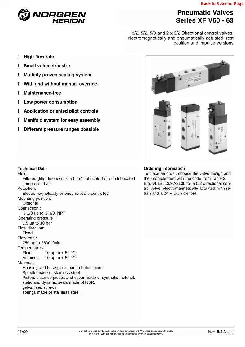
l High flow rate
l Small volumetric size
l Multiply proven sealing system
l With and without manual override
l Maintenance-free
l Low power consumption
l Application oriented pilot controls
l Manifold system for easy assembly
l Different pressure ranges possible
Technical DataFluid:
Filtered (filter fineness < 50 µm), lubricated or non-lubricatedcompressed air
Actuation:Electromagnetically or pneumatically controlled
Mounting position:Optional
Connection :G 1/8 up to G 3/8, NPT
Operating pressure :1.5 up to 10 bar
Flow direction:Fixed
Flow rate :750 up to 2600 l/min
Temperatures :Fluid: - 10 up to + 50 °CAmbient: - 10 up to + 50 °C
Material:Housing and base plate made of aluminium Spindle made of stainless steel,Piston, distance pieces and cover made of synthetic material,static and dynamic seals made of NBR, galvanised screws,springs made of stainless steel.
Pneumatic ValvesSeries XF V60 - 63
3/2, 5/2, 5/3 and 2 x 3/2 Directional control valves,electromagnetically and pneumatically actuated, rest
position and impulse versions
Ordering information To place an order, choose the valve design andthen complement with the code from Table 2.E.g. V61B513A-A213L for a 5/2 directional con-trol valve, electromagnetically actuated, with re-turn and a 24 V DC solenoid.

Symbol Type Size Pilot supply Pilot exhaust Solenoid Manual Flow Operating Pilot pressure Weight Dimensionalvariant override (l/min) pressure (bar) external (bar) (kg) drawing No.
V60A413A-A2*** XF5 G 1/8 internal not collected 1 with detent 750 2 - 8 – 0.22 M01V60A423A-A2*** XF5 G 1/8 external not collected 1 with detent 750 -0.9 - 8 3 - 8 0.22 M01V60A413D-C213A XF5 G 1/8 internal collected 2 with detent 750 2 - 10 – 0.21 M04V60A423D-C213A XF5 G 1/8 external collected 2 with detent 750 -0.9 - 10 3 - 10 0.21 M04V61B413A-A2*** XF8 G 1/4 internal not collected 1 with detent 1300 2 - 8 – 0.29 M01V61B423A-A2*** XF8 G 1/4 external not collected 1 with detent 1300 -0.9 - 8 3 - 8 0.29 M01V61B413D-C213A XF8 G 1/4 internal collected 2 with detent 1300 2 - 10 – 0.27 M04V61B423D-C213A XF8 G 1/4 external collected 2 with detent 1300 -0.9 - 10 3 - 10 0.27 M04V62C413A-A2*** XF13 G 3/8 internal not collected 1 with detent 2600 2 - 8 – 0.52 M01V62C423A-A2*** XF13 G 3/8 external not collected 1 with detent 2600 -0.9 - 8 3 - 8 0.52 M01V62C413D-C213A XF13 G 3/8 internal collected 2 with detent 2600 2 - 10 – 0.50 M04V62C423D-C213A XF13 G 3/8 external collected 2 with detent 2600 -0.9 - 10 3 - 10 0.50 M04V60A313A-A2*** XF5 G 1/8 internal not collected 1 with detent 750 2 - 8 – 0.22 M01V60A323A-A2*** XF5 G 1/8 external not collected 1 with detent 750 -0.9 - 8 3 - 8 0.22 M01V60A313D-C213A XF5 G 1/8 internal collected 2 with detent 750 2 - 10 – 0.21 M04V60A323D-C213A XF5 G 1/8 external collected 2 with detent 750 -0.9 - 10 3 - 10 0.21 M04V61B313A-A2*** XF8 G 1/4 internal not collected 1 with detent 1300 2 - 8 – 0.29 M01V61B323A-A2*** XF8 G 1/4 external not collected 1 with detent 1300 -0.9 - 8 3 - 8 0.29 M01V61B313D-C213A XF8 G 1/4 internal collected 2 with detent 1300 2 - 10 – 0.27 M04V61B323D-C213A XF8 G 1/4 external collected 2 with detent 1300 -0.9 - 10 3 - 10 0.27 M04V62C313A-A2*** XF13 G 3/8 internal not collected 1 with detent 2600 2 - 8 – 0.52 M01V62C323A-A2*** XF13 G 3/8 external not collected 1 with detent 2600 -0.9 - 8 3 - 8 0.52 M01V62C313D-C213A XF13 G 3/8 internal collected 2 with detent 2600 2 - 10 – 0.50 M04V62C323D-C213A XF13 G 3/8 external collected 2 with detent 2600 -0.9 - 10 3 - 10 0.50 M04V60A411A-A3*** XF5 G 1/8 internal not collected 1 without detent 750 1,5 - 8 – 0.30 M01V60A422A-A3*** XF5 G 1/8 external not collected 1 without detent 750 -0.9 - 8 3 - 8 0.30 M01V60A411D-C313A XF5 G 1/8 internal collected 2 without detent 750 1,5 - 10 – 0.20 M04V60A422D-C313A XF5 G 1/8 external collected 2 without detent 750 -0.9 - 10 3 - 10 0.20 M04V61B411A-A3*** XF8 G 1/4 internal not collected 1 without detent 1300 1,5 - 8 – 0.38 M01V61B422A-A3*** XF8 G 1/4 external not collected 1 without detent 1300 -0.9 - 8 3 - 8 0.38 M01V61B411D-C313A XF8 G 1/4 internal collected 2 without detent 1300 1,5 - 10 – 0.27 M04V61B422D-C313A XF8 G 1/4 external collected 2 without detent 1300 -0.9 - 10 3 - 10 0.27 M04V62C411A-A3*** XF13 G 3/8 internal not collected 1 without detent 2600 1,5 - 8 – 0.61 M01V62C422A-A3*** XF13 G 3/8 external not collected 1 without detent 2600 -0.9 - 8 3 - 8 0.61 M01V62C411D-C313A XF13 G 3/8 internal collected 2 without detent 2600 1,5 - 10 – 0.50 M04V62C422D-C313A XF13 G 3/8 external collected 2 without detent 2600 -0.9 - 10 3 - 10 0.50 M04
*** Insert voltage code from table, or 000 für version without solenoid.
XF V60 - 63
N/** 5.4.314.2 11/00Our policy is one continued research and development. We therefore reserve the rightto amend, without notice, the specifications given in this document.
Valve choice3/2 directional control valves, electropneumatically actuated
12 210
3 1
10 212
1 3
12 2 10
3 1
NC1)
NO1)
Voltage Code Power consumption Single solenoidInrush / Hold Type
22 mm Solenoid with plug interface DIN 43650 Form B12 V DC 12L 2 W V10626-A1224 V DC 13L 2 W V10626-A1324 V 50/60 Hz 14L 4 / 2.5 VA V10626-A1448 V 50/60 Hz 16L 4 / 2.5 VA V10626-A16110/120 V 50/60 Hz 18L 4 / 2.5 VA V10626-A18220/240 V 50/60 Hz 19L 6 / 5 VA V10626-A1922 mm Solenoid with plug interface “industrial standard”12 V DC 12J 2 W QM/48/160/2124 V DC 13J 2 W QM/48/127/2124 V 50/60 Hz 14J 4 / 2.5 VA QM/48/164/2148 V 50/60 Hz 16J 4 / 2.5 VA QM/48/165/21110/120 V 50/60 Hz 18J 4 / 2.5 VA QM/48/166/21220/240 V 50/60 Hz 19J 6 / 5 VA QM/48/167/21
Voltage Code Power consump. Manual Twin pilot cpl.Inrush / Hold override (with solenoids) Type
Twin pilot with plug interface DIN 43650 Form C (4 pin)24 V DC 13 A 2 W press 9031703 9000 024 00
detent 9031704 9000 024 00without 9031705 9000 024 00
Selection of solenoid and voltagePlease insert solenoid code instead of *** under Valve type.
Solenoid variant 1 Solenoid variant 2
Technical data for solenoid variants 1 + 2:Voltage tolerance: ±10%Rating: 100% EDProtection class: IP 65 with sealed plugs (ISO 6952)Connection plugs must be ordered separately – see page 13
Plug configuration, valve side / Twin pilot
Symbol Plug no. Function Actuation
1 (+) 12 (Solenoid 2)
2 (–) 12 + 14
3 (+) 14 (Solenoid 1)
PE (Ground)
123
PE

Dimensional drawings
01M
L
O
P
K
J
R S
1 (3) 3 (1)
A B
D
E
G
F H
External pilot supply
N
2
12(10)
10(12)
04
Type Version A B C D E F G H J K L M N O P R S T UXF5 V60 Rest position 35 16 – 3.2 6.5 17 G 1/8 22 16.2 28 – 114 25 25 4.5 26 35 – –
Impuls 35 – – 3.2 6.5 17 G 1/8 22 16.2 28 160 – 25 – 4.5 26 35 – –XF8 V61 Rest position 46 18 – 3.2 6.5 20 G 1/4 25 21 28 – 130 32 29 4.5 26 40 – –
Impuls 46 – – 3.2 6.5 20 G 1/4 25 21 28 179 – 32 – 4.5 26 40 – –XF13 V62 Rest position 54 21 – 4.5 8 28 G 3/8 34 24.4 44 – 146 12 36 4.5 36 55 – –
Impuls 54 – – 4.5 8 28 G 3/8 34 24.4 44 196 – 12 – 4.5 36 55 – –
Dimensional table 01
XF V60 - 63
11/00 N/** 5.4.314.3Our policy is one continued research and development. We therefore reserve the rightto amend, without notice, the specifications given in this document.
Solenoid 2 10(12)
Solenoid 1 12(10)
L
O
P
K
J
R S
1 (3) 3 (1)
A B
D
E
G
F H
External pilot supply
N
2
U
T
Pilot exhaust
Type Version A B C D E F G H J K L M N O P R S T UXF5 V60 Double pilot 35 16 – 3.2 6.5 17 G 1/8 22 16.2 28 119 – 25 25 4.5 26 35 45 15XF8 V61 Double pilot 46 18 – 3.2 6.5 20 G 1/4 25 21 28 133 – 32 29 4.5 26 40 45 15XF13 V62 Double pilot 54 21 – 4.5 8 28 G 3/8 34 24.4 44 148 – 12 36 4.5 36 55 45 15
Dimensional table 04

XF V60 - 63
N/** 5.4.314.4 11/00Our policy is one continued research and development. We therefore reserve the rightto amend, without notice, the specifications given in this document.
Valve choice2 x 3/2 directional control valves, electropneumatically actuated
*** Insert voltage code from table, or 000 für version without solenoid.1) NC – Normally closed, NO – Normally open
Symbol Type Size Pilot supply Pilot exhaust Solenoid Manual Flow Operating Pilot pressure Weight Dimensionalvariant override (l/min) pressure (bar) external (bar) (kg) drawing No.
V60AA11A-A2*** XF5 G 1/8 internal not collected 1 with detent 500 2 - 8 – 0.34 M02V60AA11D-C213A XF5 G 1/8 internal collected 2 with detent 500 2 - 10 – 0.24 M05V61BA11A-A2*** XF8 G 1/4 internal not collected 1 with detent 950 2 - 8 – 0.43 M02V61BA11D-C213A XF8 G 1/4 internal collected 2 with detent. 950 2 - 10 – 0.33 M05V62CA11A-A2*** XF13 G 3/8 internal not collected 1 with detent 1900 2 - 8 – 0.73 M02V62CA11D-C213A XF13 G 3/8 internal collected 2 with detent 1900 2 - 10 – 0.63 M05V60AB11A-A2*** XF5 G 1/8 internal not collected 1 with detent 500 2 - 8 – 0.34 M02V60AB11D-C213A XF5 G 1/8 internal collected 2 with detent 500 2 - 10 – 0.,24 M05V61BB11A-A2*** XF8 G 1/4 internal not collected 1 with detent 950 2 - 8 – 0.43 M02V61BB11D-C213A XF8 G 1/4 internal collected 2 with detent 950 2 - 10 – 0.33 M05V62CB11A-A2*** XF13 G 3/8 internal not collected 1 with detent 1900 2 - 8 – 0.73 M02V62CB11D-C213A XF13 G 3/8 internal collected 2 with detent 1900 2 - 10 – 0.63 M05V60AC11A-A2*** XF5 G 1/8 internal not collected 1 with detent 500 2 - 8 – 0.34 M02V60AC11D-C213A XF5 G 1/8 internal collected 2 with detent 500 2 - 10 – 0.24 M05V61BC11A-A2*** XF8 G 1/4 internal not collected 1 with detent 950 2 - 8 – 0.43 M02V61BC11D-C213A XF8 G 1/4 internal collected 2 with detent 950 2 - 10 – 0.33 M05V62CC11A-A2*** XF13 G 3/8 internal not collected 1 with detent 1900 2 - 8 – 0.73 M02V62CC11D-C213A XF13 G 3/8 internal collected 2 with detent 1900 2 - 10 – 0.63 M05
14 4 10
5 1
10 2 12
3
10 4 14
51
12
3
2 10
10 4 14
5
1
10 2 12
3
NC/NC1)
NO/NO1)
NO/NC1)
Voltage Code Power consumption Single solenoidInrush / Hold Type
22 mm Solenoid with plug interface DIN 43650 Form B12 V DC 12L 2 W V10626-A1224 V DC 13L 2 W V10626-A1324 V 50/60 Hz 14L 4 / 2.5 VA V10626-A1448 V 50/60 Hz 16L 4 / 2.5 VA V10626-A16110/120 V 50/60 Hz 18L 4 / 2.5 VA V10626-A18220/240 V 50/60 Hz 19L 6 / 5 VA V10626-A1922 mm Solenoid with plug interface “industrial standard”12 V DC 12J 2 W QM/48/160/2124 V DC 13J 2 W QM/48/127/2124 V 50/60 Hz 14J 4 / 2.5 VA QM/48/164/2148 V 50/60 Hz 16J 4 / 2.5 VA QM/48/165/21110/120 V 50/60 Hz 18J 4 / 2.5 VA QM/48/166/21220/240 V 50/60 Hz 19J 6 / 5 VA QM/48/167/21
Voltage Code Power consump. Manual Twin pilot cpl.Inrush / Hold override (with solenoids) Type
Twin pilot with plug interface DIN 43650 Form C (4 pin)24 V DC 13 A 2 W press 9031703 9000 024 00
detent 9031704 9000 024 00without 9031705 9000 024 00
Selection of solenoid and voltagePlease insert solenoid code instead of *** under Valve type.
Solenoid variant 1 Solenoid variant 2
Technical data for solenoid variants 1 + 2:Voltage tolerance: ±10%Rating: 100% EDProtection class: IP 65 with sealed plugs (ISO 6952)Connection plugs must be ordered separately – see page 13
Plug configuration, valve side / Twin pilot
Symbol Plug no. Function Actuation
1 (+) 12 (Solenoid 2)
2 (–) 12 + 14
3 (+) 14 (Solenoid 1)
PE (Ground)
123
PE
Dimensional drawings
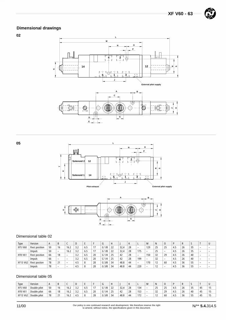
02
05
XF V60 - 63
11/00 N/** 5.4.314.5Our policy is one continued research and development. We therefore reserve the rightto amend, without notice, the specifications given in this document.
M
L
O
P
K
J
R S
1 5 3
C
D
E
G
F H
External pilot supply
N
A B
24
14 12
Type Version A B C D E F G H J K L M N O P R S T UXF5 V60 Rest position 50 16 16.2 3.2 6.5 17 G 1/8 22 32,4 28 – 129 25 25 4.5 26 35 – –
Impuls 50 – 16.2 3.2 6.5 17 G 1/8 22 32,4 28 175 – 25 – 4.5 26 35 – –XF8 V61 Rest position 66 18 – 3.2 6.5 20 G 1/4 25 42 28 – 150 32 29 4.5 26 40 – –
Impuls 66 – – 3.2 6.5 20 G 1/4 25 42 28 199 – 32 – 4.5 26 40 – –XF13 V62 Rest postion 78 21 – 4.5 8 28 G 3/8 34 48.8 44 – 170 12 60 4.5 36 55 – –
Impuls 78 – – 4.5 8 28 G 3/8 34 48.8 44 220 – 12 – 4.5 36 55 – –
Dimensional table 02
Solenoid 2 12
Solenoid 1 14
L
O
P
K
J
R S
A B
D
E
G
F H
External pilot supply
N
U
T
Pilot exhaust
1 5 3
24
Type Version A B C D E F G H J K L M N O P R S T UXF5 V60 Double pilot 50 16 16.2 3.2 6.5 17 G 1/8 22 32,4 28 134 – 25 25 4.5 26 35 45 15XF8 V61 Double pilot 66 18 16.2 3.2 6.5 20 G 1/4 25 42 28 153 – 32 29 4.5 26 40 45 15XF13 V62 Double pilot 78 21 16.2 4.5 8 28 G 3/8 34 48.8 44 172 – 12 60 4.5 36 55 45 15
Dimensional table 05

Symbol Type Size Pilot supply Pilot exhaust Solenoid Manual Flow Operating Pilot pressure Weight Dimensionalvariant override (l/min) pressure (bar) external (bar) (kg) drawing No.
V60A513A-A2*** XF5 G 1/8 internal not collected 1 with detent 750 2 - 8 – 0.24 M02V60A523A-A2*** XF5 G 1/8 external not collected 1 with detent 750 -0.9 - 8 3 - 8 0.24 M02V60A513D-C213A XF5 G 1/8 internal collected 2 with detent 750 2 - 10 – 0.23 M05V60A523D-C213A XF5 G 1/8 external collected 2 with detent 750 -0.9 - 10 3 - 10 0.23 M05V61B513A-A2*** XF8 G 1/4 internal not collected 1 with detent 1300 2 - 8 – 0.33 M02V61B523A-A2*** XF8 G 1/4 external not collected 1 with detent 1300 -0.9 - 8 3 - 8 0.33 M02V61B513D-C213A XF8 G 1/4 internal collected 2 with detent 1300 2 - 10 – 0.32 M05V61B523D-C213A XF8 G 1/4 external collected 2 with detent 1300 -0.9 - 10 3 - 10 0.32 M05V62C513A-A2*** XF13 G 3/8 internal not collected 1 with detent 2600 2 - 8 – 0.62 M02V62C523A-A2*** XF13 G 3/8 external not collected 1 with detent 2600 -0.9 - 8 3 - 8 0.62 M02V62C513D-C213A XF13 G 3/8 internal collected 2 with detent 2600 2 - 10 – 0.61 M05V62C523D-C213A XF13 G 3/8 external collected 2 with detent 2600 -0.9 - 10 3 - 10 0.61 M05V60A511A-A3*** XF5 G 1/8 internal not collected 1 without detent 750 2 - 8 – 0.33 M02V60A522A-A3*** XF5 G 1/8 external not collected 1 without detent 750 -0.9 - 8 3 - 8 0.33 M02V60A511D-C313A XF5 G 1/8 internal collected 2 without detent 750 2 - 10 – 0.23 M05V60A522D-C313A XF5 G 1/8 external collected 2 without detent 750 -0.9 - 10 3 - 10 0.23 M05V61B511A-A3*** XF8 G 1/4 internal not collected 1 without detent 1300 2 - 8 – 0.42 M02V61B522A-A3*** XF8 G 1/4 external not collected 1 without detent 1300 -0.9 - 8 3 - 8 0.42 M02V61B511D-C313A XF8 G 1/4 internal collected 2 without detent 1300 2 - 10 – 0.32 M05V61B522D-C313A XF8 G 1/4 external collected 2 without detent 1300 -0.9 - 10 3 - 10 0.32 M05V62C511A-A3*** XF13 G 3/8 internal not collected 1 without detent 2600 2 - 8 – 0.72 M02V62C522A-A3*** XF13 G 3/8 external not collected 1 without detent 2600 -0.9 - 8 3 - 8 0.72 M02V62C511D-C313A XF13 G 3/8 internal collected 2 without detent 2600 2 - 10 – 0.62 M05V62C522D-C313A XF13 G 3/8 external collected 2 without detent 2600 -0.9 - 10 3 - 10 0.62 M05
Valve choice5/2 directional control valves, electropneumatically actuated
14 4 212
5 1 3
14 4 2 12
5 1 3
*** Insert voltage code from table, or 000 für version without solenoid.
XF V60 - 63
N/** 5.4.314.6 11/00Our policy is one continued research and development. We therefore reserve the rightto amend, without notice, the specifications given in this document.
Voltage Code Power consumption Single solenoidInrush / Hold Type
22 mm Solenoid with plug interface DIN 43650 Form B12 V DC 12L 2 W V10626-A1224 V DC 13L 2 W V10626-A1324 V 50/60 Hz 14L 4 / 2.5 VA V10626-A1448 V 50/60 Hz 16L 4 / 2.5 VA V10626-A16110/120 V 50/60 Hz 18L 4 / 2.5 VA V10626-A18220/240 V 50/60 Hz 19L 6 / 5 VA V10626-A1922 mm Solenoid with plug interface “industrial standard”12 V DC 12J 2 W QM/48/160/2124 V DC 13J 2 W QM/48/127/2124 V 50/60 Hz 14J 4 / 2.5 VA QM/48/164/2148 V 50/60 Hz 16J 4 / 2.5 VA QM/48/165/21110/120 V 50/60 Hz 18J 4 / 2.5 VA QM/48/166/21220/240 V 50/60 Hz 19J 6 / 5 VA QM/48/167/21
Voltage Code Power consump. Manual Twin pilot cpl.Inrush / Hold override (with solenoids) Type
Twin pilot with plug interface DIN 43650 Form C (4 pin)24 V DC 13 A 2 W press 9031703 9000 024 00
detent 9031704 9000 024 00without 9031705 9000 024 00
Selection of solenoid and voltagePlease insert solenoid code instead of *** under Valve type.
Solenoid variant 1 Solenoid variant 2
Technical data for solenoid variants 1 + 2:Voltage tolerance: ±10%Rating: 100% EDProtection class: IP 65 with sealed plugs (ISO 6952)Connection plugs must be ordered separately – see page 13
Plug configuration, valve side / Twin pilot
Symbol Plug no. Function Actuation
1 (+) 12 (Solenoid 2)
2 (–) 12 + 14
3 (+) 14 (Solenoid 1)
PE (Ground)
123
PE

11/00 N/** 5.4.314.7Our policy is one continued research and development. We therefore reserve the rightto amend, without notice, the specifications given in this document.
XF V60 - 63
Dimensional drawings
02
05
M
L
O
P
K
J
R S
1 5 3
C
D
E
G
F H
External pilot supply
N
A B
24
14 12
Type Version A B C D E F G H J K L M N O P R S T UXF5 V60 Rest position 50 16 16.2 3.2 6.5 17 G 1/8 22 32,4 28 – 129 25 25 4.5 26 35 – –
Impuls 50 – 16.2 3.2 6.5 17 G 1/8 22 32,4 28 175 – 25 – 4.5 26 35 – –XF8 V61 Rest position 66 18 – 3.2 6.5 20 G 1/4 25 42 28 – 150 32 29 4.5 26 40 – –
Impuls 66 – – 3.2 6.5 20 G 1/4 25 42 28 199 – 32 – 4.5 26 40 – –XF13 V62 Rest position 78 21 – 4.5 8 28 G 3/8 34 48.8 44 – 170 12 60 4.5 36 55 – –
Impuls 78 – – 4.5 8 28 G 3/8 34 48.8 44 220 – 12 – 4.5 36 55 – –
Dimensional table 02
Solenoid 2 12
Solenoid 1 14
L
O
P
K
J
R S
A B
D
E
G
F H
External pilot supply
N
U
T
Pilot exhaust
1 5 3
24
Type Version A B C D E F G H J K L M N O P R S T UXF5 V60 Double pilot 50 16 16.2 3.2 6.5 17 G 1/8 22 32,4 28 134 – 25 25 4.5 26 35 45 15XF8 V61 Double pilot 66 18 16.2 3.2 6.5 20 G 1/4 25 42 28 153 – 32 29 4.5 26 40 45 15XF13 V62 Double pilot 78 21 16.2 4.5 8 28 G 3/8 34 48.8 44 172 – 12 60 4.5 36 55 45 15
Dimensional table 05

N/** 5.4.314.8 11/00Our policy is one continued research and development. We therefore reserve the rightto amend, without notice, the specifications given in this document.
XF V60 - 63
*** Insert voltage code from table, or 000 für version without solenoid.1) NC – Normally closed, NO – Normally open, 2+4 – Central open pressure
Symbol Type Size Pilot supply Pilot exhaust Solenoid Manual Flow Operating Pilot pressure Weight Dimensionalvariant override (l/min) pressure (bar) external (bar) (kg) drawing No.
V60A611A-A2*** XF5 G 1/8 internal not collected 1 with detent 500 3 - 8 – 0.35 M03V60A622A-A2*** XF5 G 1/8 external not collected 1 with detent 500 -0.9 - 8 3 - 8 0.35 M03V60A611D-C213A XF5 G 1/8 internal collected 2 with detent 500 3 - 10 – 0.25 M06V60A622D-C213A XF5 G 1/8 external collected 2 with detent 500 -0.9 - 10 3 - 10 0.25 M06V61B611A-A2*** XF8 G 1/4 internal not collected 1 with detent 950 3 - 8 – 0.47 M03V61B622A-A2*** XF8 G 1/4 external not collected 1 with detent 950 -0.9 - 8 3 - 8 0.47 M03V61B611D-C213A XF8 G 1/4 internal collected 2 with detent 950 3 - 10 – 0.37 M06V61B622D-C213A XF8 G 1/4 external collected 2 with detent 9500 -0.9 - 10 3 - 10 0.37 M06V62C611A-A2*** XF13 G 3/8 internal not collected 1 with detent 1900 3 - 8 – 0.81 M03V62C622A-A2*** XF13 G 3/8 external not collected 1 with detent 1900 -0.9 - 8 3 - 8 0.81 M03V62C611D-C213A XF13 G 3/8 internal collected 2 with detent 1900 3 - 10 – 0.71 M06V62C611D-C213A XF13 G 3/8 external collected 2 with detent 1900 -0.9 - 10 3 - 10 0.71 M06V60A711A-A2*** XF5 G 1/8 internal not collected 1 with detent 500 3 - 8 – 0.35 M03V60A722A-A2*** XF5 G 1/8 external not collected 1 with detent 500 -0.9 - 8 3 - 8 0.35 M03V60A711D-C213A XF5 G 1/8 internal collected 2 with detent 500 3 - 10 – 0.25 M06V60A722D-C213A XF5 G 1/8 external collected 2 with detent 500 -0.9 - 10 3 - 10 0.25 M06V61B711A-A2*** XF8 G 1/4 internal not collected 1 with detent 950 3 - 8 – 0.47 M03V61B722A-A2*** XF8 G 1/4 external not collected 1 with detent 950 -0.9 - 8 3 - 8 0.47 M03V61B711D-C213A XF8 G 1/4 internal collected 2 with detent 950 3 - 10 – 0.37 M06V61B722D-C213A XF8 G 1/4 external collected 2 with detent 950 -0.9 - 10 3 - 10 0.37 M06V62C711A-A2*** XF13 G 3/8 internal not collected 1 with detent 1900 3 - 8 – 0.81 M03V62C722A-A2*** XF13 G 3/8 external not collected 1 with detent 1900 -0.9 - 8 3 - 8 0.81 M03V62C711D-C213A XF13 G 3/8 internal collected 2 with detent 1900 3 - 10 – 0.71 M06V62C722D-C213A XF13 G 3/8 external collected 2 with detent 1900 -0.9 - 10 3 - 10 0.71 M06V60A811A-A2*** XF5 G 1/8 internal not collected 1 with detent 500 3 - 8 – 0.35 M03V60A822A-A2*** XF5 G 1/8 external not collected 1 with detent 500 -0.9 - 8 3 - 8 0.35 M03V60A811D-C213A XF5 G 1/8 internal collected 2 with detent 500 3 - 10 – 0.25 M06V60A822D-C213A XF5 G 1/8 external collected 2 with detent 500 -0.9 - 10 3 - 10 0.25 M06V61B811A-A2*** XF8 G 1/4 internal not collected 1 with detent 950 3 - 8 – 0.47 M03V61B822A-A2*** XF8 G 1/4 external not collected 1 with detent 950 -0.9 - 8 3 - 8 0.47 M03V61B811D-C213A XF8 G 1/4 internal collected 2 with detent 950 3 - 10 – 0.37 M06V61B822D-C213A XF8 G 1/4 external collected 2 with detent 950 -0.9 - 10 3 - 10 0.37 M06V62C811A-A2*** XF13 G 3/8 internal not collected 1 with detent 1900 3 - 8 – 0.81 M03V62C822A-A2*** XF13 G 3/8 external not collected 1 with detent 1900 -0.9 - 8 3 - 8 0.81 M03V62C811D-C213A XF13 G 3/8 internal collected 2 with detent 1900 3 - 10 – 0.71 M06V62C822D-C213A XF13 G 3/8 external collected 2 with detent 1900 -0.9 - 10 3 - 10 0.71 M06
Valve choice5/3 directional control valves, electropneumatically actuated
144 2
12
5 1 3
144 2
12
5 1 3
144 2
12
5 1 3
NC1)
NO1)
2+41)
Voltage Code Power consumption Single solenoidInrush / Hold Type
22 mm Solenoid with plug interface DIN 43650 Form B12 V DC 12L 2 W V10626-A1224 V DC 13L 2 W V10626-A1324 V 50/60 Hz 14L 4 / 2.5 VA V10626-A1448 V 50/60 Hz 16L 4 / 2.5 VA V10626-A16110/120 V 50/60 Hz 18L 4 / 2.5 VA V10626-A18220/240 V 50/60 Hz 19L 6 / 5 VA V10626-A1922 mm Solenoid with plug interface “industrial standard”12 V DC 12J 2 W QM/48/160/2124 V DC 13J 2 W QM/48/127/2124 V 50/60 Hz 14J 4 / 2.5 VA QM/48/164/2148 V 50/60 Hz 16J 4 / 2.5 VA QM/48/165/21110/120 V 50/60 Hz 18J 4 / 2.5 VA QM/48/166/21220/240 V 50/60 Hz 19J 6 / 5 VA QM/48/167/21
Voltage Code Power consump. Manual Twin pilot cpl.Inrush / Hold override (with solenoids) Type
Twin pilot with plug interface DIN 43650 Form C (4 pin)24 V DC 13 A 2 W press 9031703 9000 024 00
detent 9031704 9000 024 00without 9031705 9000 024 00
Selection of solenoid and voltagePlease insert solenoid code instead of *** under Valve type.
Solenoid variant 1 Solenoid variant 2
Technical data for solenoid variants 1 + 2:Voltage tolerance: ±10%Rating: 100% EDProtection class: IP 65 with sealed plugs (ISO 6952)Connection plugs must be ordered separately – see page 13
Plug configuration, valve side / Twin pilot
Symbol Plug no. Function Actuation
1 (+) 12 (Solenoid 2)
2 (–) 12 + 14
3 (+) 14 (Solenoid 1)
PE (Ground)
123
PE

XF V60 - 63
11/00 N/** 5.4.314.9Our policy is one continued research and development. We therefore reserve the rightto amend, without notice, the specifications given in this document.
Dimensional drawings
03
Solenoid 2 12
Solenoid 1 14
L
O
P
K
J
R S
A B
D
E
G
F H
External pilot valve
N
U
T
Pilot exhaust
1 5 3
24
06
Dimensional table 06
Type Version A B C D E F G H J K L M N O P R S T UXF5 V60 Double pilot 50 30 16.2 3.2 6.5 17 G 1/8 22 32,4 28 148 – 25 39 4.5 26 35 45 15XF8 V61 Double pilot 66 36 21 3.2 6.5 20 G 1/4 25 42 28 171 – 32 47 4.5 26 40 45 15XF13 V62 Double pilot 78 43 24.4 4.5 8 28 G 3/8 34 48.8 44 194 – 12 82 4.5 36 55 45 15
L
O
P
K
J
R S
1 5 3
C
D
E
G
F H
External pilot supply
N
A B
24
14 12
Dimensional table 03
Type Version A B C D E F G H J K L M N O P R S T UXF5 V60 Rest position 50 – 16.2 3.2 6.5 17 G 1/8 22 32,4 28 189 – 25 – 4.5 26 35 – –XF8 V61 Rest position 66 – 21 3.2 6.5 20 G 1/4 25 42 28 217 – 32 – 4.5 26 40 – –XF13 V62 Rest position 78 – 24.4 4.5 8 28 G 3/8 34 48.8 44 242 – 12 – 4.5 36 55 – –
XF V60 - 63
N/** 5.4.314.10 11/00Our policy is one continued research and development. We therefore reserve the rightto amend, without notice, the specifications given in this document.
Symbol Type Size Operator Operator Flow Operating Pilot pressure Weight Dimensional12 10 (l/min) pressure (bar) external (bar) (kg) drawing No.
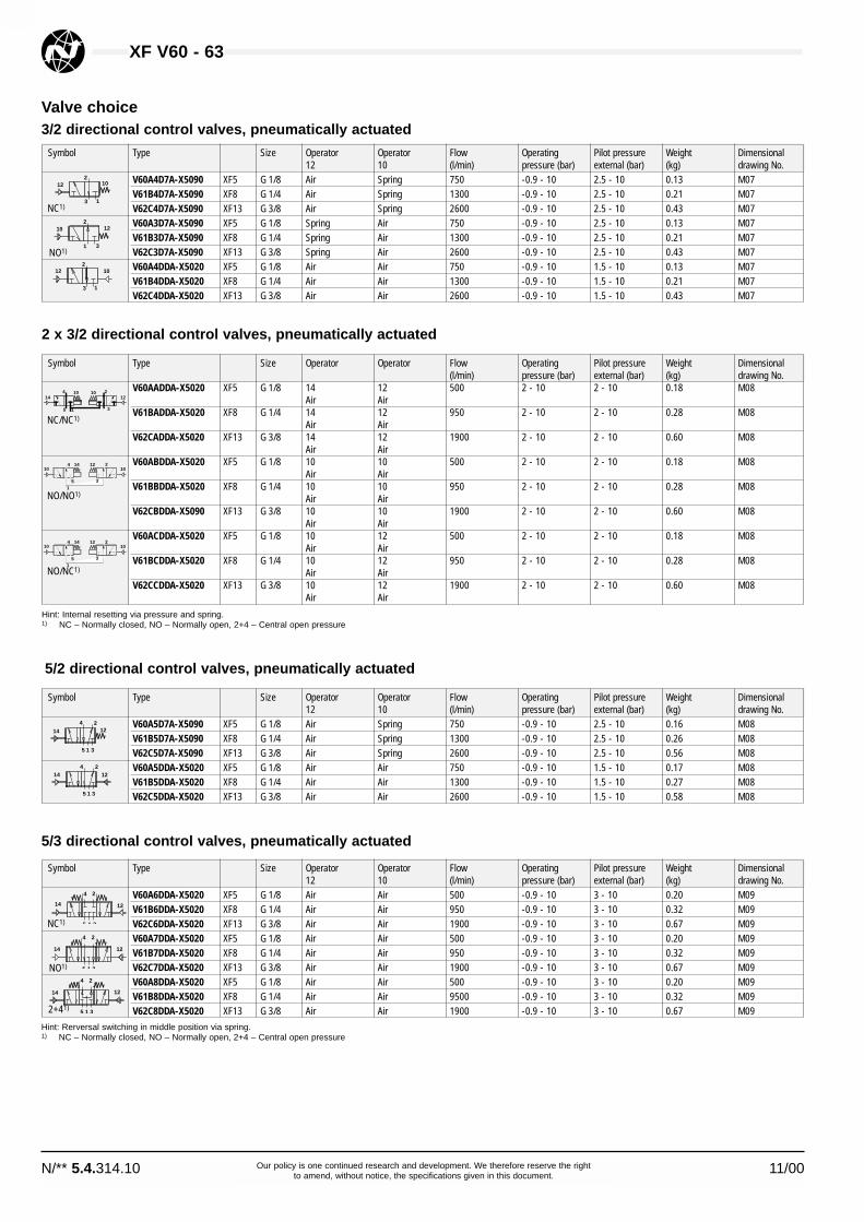
V60A4D7A-X5090 XF5 G 1/8 Air Spring 750 -0.9 - 10 2.5 - 10 0.13 M07V61B4D7A-X5090 XF8 G 1/4 Air Spring 1300 -0.9 - 10 2.5 - 10 0.21 M07V62C4D7A-X5090 XF13 G 3/8 Air Spring 2600 -0.9 - 10 2.5 - 10 0.43 M07V60A3D7A-X5090 XF5 G 1/8 Spring Air 750 -0.9 - 10 2.5 - 10 0.13 M07V61B3D7A-X5090 XF8 G 1/4 Spring Air 1300 -0.9 - 10 2.5 - 10 0.21 M07V62C3D7A-X5090 XF13 G 3/8 Spring Air 2600 -0.9 - 10 2.5 - 10 0.43 M07V60A4DDA-X5020 XF5 G 1/8 Air Air 750 -0.9 - 10 1.5 - 10 0.13 M07V61B4DDA-X5020 XF8 G 1/4 Air Air 1300 -0.9 - 10 1.5 - 10 0.21 M07V62C4DDA-X5020 XF13 G 3/8 Air Air 2600 -0.9 - 10 1.5 - 10 0.43 M07
Valve choice3/2 directional control valves, pneumatically actuated
122
10
3 1
102
12
1 3
122
10
3 1
NC1)
NO1)
Symbol Type Size Operator Operator Flow Operating Pilot pressure Weight Dimensional(l/min) pressure (bar) external (bar) (kg) drawing No.
V60AADDA-X5020 XF5 G 1/8 14 12 500 2 - 10 2 - 10 0.18 M08Air Air
V61BADDA-X5020 XF8 G 1/4 14 12 950 2 - 10 2 - 10 0.28 M08Air Air
V62CADDA-X5020 XF13 G 3/8 14 12 1900 2 - 10 2 - 10 0.60 M08Air Air
V60ABDDA-X5020 XF5 G 1/8 10 10 500 2 - 10 2 - 10 0.18 M08Air Air
V61BBDDA-X5020 XF8 G 1/4 10 10 950 2 - 10 2 - 10 0.28 M08Air Air
V62CBDDA-X5090 XF13 G 3/8 10 10 1900 2 - 10 2 - 10 0.60 M08Air Air
V60ACDDA-X5020 XF5 G 1/8 10 12 500 2 - 10 2 - 10 0.18 M08Air Air
V61BCDDA-X5020 XF8 G 1/4 10 12 950 2 - 10 2 - 10 0.28 M08Air Air
V62CCDDA-X5020 XF13 G 3/8 10 12 1900 2 - 10 2 - 10 0.60 M08Air Air
2 x 3/2 directional control valves, pneumatically actuated
144 10
5 1
10 212
3
51
10
3
104 14 12 2
51
10
3
104 14 12 2
NC/NC1)
NO/NO1)
NO/NC1)
Hint: Internal resetting via pressure and spring.1) NC – Normally closed, NO – Normally open, 2+4 – Central open pressure
Hint: Rerversal switching in middle position via spring.1) NC – Normally closed, NO – Normally open, 2+4 – Central open pressure
5/2 directional control valves, pneumatically actuated
Symbol Type Size Operator Operator Flow Operating Pilot pressure Weight Dimensional12 10 (l/min) pressure (bar) external (bar) (kg) drawing No.
V60A5D7A-X5090 XF5 G 1/8 Air Spring 750 -0.9 - 10 2.5 - 10 0.16 M08V61B5D7A-X5090 XF8 G 1/4 Air Spring 1300 -0.9 - 10 2.5 - 10 0.26 M08V62C5D7A-X5090 XF13 G 3/8 Air Spring 2600 -0.9 - 10 2.5 - 10 0.56 M08V60A5DDA-X5020 XF5 G 1/8 Air Air 750 -0.9 - 10 1.5 - 10 0.17 M08V61B5DDA-X5020 XF8 G 1/4 Air Air 1300 -0.9 - 10 1.5 - 10 0.27 M08V62C5DDA-X5020 XF13 G 3/8 Air Air 2600 -0.9 - 10 1.5 - 10 0.58 M08
144 2
12
5 1 3
144 2
12
5 1 3
Symbol Type Size Operator Operator Flow Operating Pilot pressure Weight Dimensional12 10 (l/min) pressure (bar) external (bar) (kg) drawing No.
V60A6DDA-X5020 XF5 G 1/8 Air Air 500 -0.9 - 10 3 - 10 0.20 M09V61B6DDA-X5020 XF8 G 1/4 Air Air 950 -0.9 - 10 3 - 10 0.32 M09V62C6DDA-X5020 XF13 G 3/8 Air Air 1900 -0.9 - 10 3 - 10 0.67 M09V60A7DDA-X5020 XF5 G 1/8 Air Air 500 -0.9 - 10 3 - 10 0.20 M09V61B7DDA-X5020 XF8 G 1/4 Air Air 950 -0.9 - 10 3 - 10 0.32 M09V62C7DDA-X5020 XF13 G 3/8 Air Air 1900 -0.9 - 10 3 - 10 0.67 M09V60A8DDA-X5020 XF5 G 1/8 Air Air 500 -0.9 - 10 3 - 10 0.20 M09V61B8DDA-X5020 XF8 G 1/4 Air Air 9500 -0.9 - 10 3 - 10 0.32 M09V62C8DDA-X5020 XF13 G 3/8 Air Air 1900 -0.9 - 10 3 - 10 0.67 M09
14
4 2
12
5 1 3
14
4 2
12
5 1 3
14
4 2
12
5 1 3
NC1)
NO1)
2+41)
5/3 directional control valves, pneumatically actuated

Dimensional drawings
07M
L
O
P
K
J
R S
1 (3) 3 (1)
A B
D
E
G
F H
N
2
14(12)
12(14)
T
M
L
O
P
K
J
R S
1 5 3
C
D
E
G
F H
N
U
A B
24
1214
T
08
Type Version A B C D E F G H J K L M N O P R S T UXF5 V60 3/2 Rest posit. 35 29 – 3.2 6.5 17 G 1/8 22 16.2 28 80 86 25 37 4.5 26 35 17 M5XF5 V60 3/2 Impuls 35 23 – 3.2 6.5 17 G 1/8 22 16.2 28 80 86 25 31 4.5 26 35 17 M5XF8 V61 3/2 Rest posit. 46 35 – 3.2 6.5 20 G 1/4 25 21 28 94 105 32 46 4.5 26 40 18 M5XF8 V61 3/2 Impuls 46 24 – 3.2 6.5 20 G 1/4 25 21 28 94 105 32 35 4.5 26 40 18 M5XF13 V62 3/2 Rest posit. 54 43 – 4.5 8 28 G 3/8 34 24.4 44 108 124 12 58 4.5 36 55 21 M5XF13 V62 3/2 Impuls 54 27 – 4.5 8 28 G 3/8 34 24.4 44 108 124 12 42 4.5 36 55 21 M5
Dimensional table 07
XF V60 - 63
11/00 N/** 5.4.314.11Our policy is one continued research and development. We therefore reserve the rightto amend, without notice, the specifications given in this document.
09 L
O
P
K
J
R S1 5 3
C
D
E
G
F H
External pilot supply
N
T A B
24
14 12
Type Version A B C D E F G H J K L M N O P R S T UXF5 V60 5/3 50 37 16.2 3.2 6.5 17 G 1/8 22 32.4 28 109 – 25 45 4.5 26 35 17 M5XF8 V61 5/3 66 42 21 3.2 6.5 20 G 1/4 25 42 28 132 – 32 53 4.5 26 40 18 M5XF13 V62 5/3 78 49 24.4 4.5 8 28 G 3/8 34 48.8 44 154 – 12 88 4.5 36 55 21 M5
Dimensional table 09
Type Version A B C D E F G H J K L M N O P R S T UXF5 V60 5/2 Rest pos. 50 29 16.2 3.2 6.5 17 G 1/8 22 32.4 28 95 101 25 37 4.5 26 35 17 M5XF5 V60 5/2 Imp.+2x3/2 50 23 16.2 3.2 6.5 17 G 1/8 22 32.4 28 95 101 25 31 4.5 26 35 17 M5XF8 V61 5/2 Rest pos. 66 35 21 3.2 6.5 20 G 1/4 25 42 28 114 125 32 46 4.5 26 40 18 M5XF8 V61 5/2 Imp.+2x3/2 66 24 21 3.2 6.5 20 G 1/4 25 42 28 114 125 32 35 4.5 26 40 18 M5XF13 V62 5/2 Rest pos. 78 43 24.4 4.5 8 28 G 3/8 34 48.8 44 132 148 12 82 4.5 36 55 21 M5XF13 V62 5/2 Imp.+2x3/2 78 27 24.4 4.5 8 28 G 3/8 34 48.8 44 132 148 12 66 4.5 36 55 21 M5
Dimensional table 08

XF V60 - 63
N/** 5.4.314.12 11/00Our policy is one continued research and development. We therefore reserve the rightto amend, without notice, the specifications given in this document.
Manifold plate 2fold + 3fold
GF E
AC
D
B
M
H
NKJ
U
O P RS
T
L
XF Manifold SystemManifold plate
* Necessary for separate supply of two different pressures.** For closing reserve valve ports.
Included in the delivery scope: seals and fastening screws.
Dimensional drawings
GF E
AB
CD
J K N
M
H
U
R
O P
T
L
Accessories
Valve ports XF5 / V60 XF8 / V61 XF13 / V62Type Weight (kg) Type Weight (kg) Type Weight (kg)
2 2221002 0000 000 00 0.23 2221102 0000 000 00 0.28 2221202 0000 000 00 0.503 2221003 0000 000 00 0.28 2221103 0000 000 00 0.45 2221203 0000 000 00 0.854 2221004 0000 000 00 0.61 2221104 0000 000 00 0.72 2221204 0000 000 00 1.256 2221006 0000 000 00 0.86 2221106 0000 000 00 1.02 2221206 0000 000 00 1.798 2221008 0000 000 00 1.11 2221108 0000 000 00 1.32 2221208 0000 000 00 2.3310 2221010 0000 000 00 1.36 2221110 0000 000 00 1.62 2221210 0000 000 00 2.8712 2221012 0000 000 00 1.61 2221112 0000 000 00 1.92 2221212 0000 000 00 3.4114 2221014 0000 000 00 1.86 2221114 0000 000 00 2.22 2221214 0000 000 00 3.9516 2221016 0000 000 00 2.11 2221116 0000 000 00 2.52 2221216 0000 000 00 4.4918 2221018 0000 000 00 2.36 2221118 0000 000 00 2.82 2221218 0000 000 00 5.0320 2221020 0000 000 00 2.61 2221120 0000 000 00 3.12 2221220 0000 000 00 5.57
For manifold Blanking plate complete** Pressure shut-off part for 2fold + 3fold* Pressure shut-off part for 4fold – 20fold*Type Type Type
XF5 / V60 0100561 0000 000 00 0701208 0000 000 00 0100567 0000 000 00XF8 / V61 0100563 0000 000 00 0701209 0000 000 00 0100569 0000 000 00XF13 / V62 0100565 0000 000 00 0701210 0000 000 00 0100571 0000 000 00
Manifold plate 4fold – 20fold
Type A B C D E F G H J K L M N O P R S T UXF5–2fold 49 98 30 16 8 11 21 32 11 35,5 46 G 1/8 G 1/4 6 86 18 23 for M5XF5–3-20fold 49 98 30 16 8 11 21 32 11 35,5 (x·23)+23 G 1/8 G 1/4 6 86 6.5 (x·23)+10 23 for M5XF8–2fold 52 104 26 9 8 13 20 33 10 35,5 52 G 1/8 G 3/8 40 24 26 26 for M5XF8–3-20fold 52 104 26 9 8 13 20 33 10 35,5 (x·26)+23 G 1/8 G 3/8 40 24 6.5 (x·26)+10 26 for M5XF13–2fold 60 120 29 9 8 15 22 38 13 35,5 70 G 1/8 G 1/2 44 32 35 35 for M6XF13–3-20fold 60 120 29 9 8 15 22 38 13 35,5 (x·35)+26 G 1/8 G 1/2 44 32 7 (x·35)+12 35 for M6
Dimensional table

XF V60 - 63
11/00 N/** 5.4.314.13Our policy is one continued research and development. We therefore reserve the rightto amend, without notice, the specifications given in this document.
Device plug connectors for actuating solenoids with protection class IP 65
Picture Designation Electrical circuit diagram Application temperature Operating voltage Type(°C) (V)
Connector acc. to industrial -40 ... +125 12 ... 250 DC/AC 0657868 0000 000 00standard, without cablewithout LED
Connector acc. to DIN 43650 -40 ... +125 12 ... 250 DC/AC 0680003 0000 000 00Form B, without cablewithout LED
Connector acc. to industrial -40 ... +100 15 ... 30 DC 0680000 0000 000 00standard, without cable, withLED and extinguished diode -40 ... +100 150 ... 250 DC/AC 0680001 0000 000 00or glow lamp
Connector acc. to DIN 43650 -40 ... +100 15 ... 30 DC 0664811 0000 000 00Form B, without cable, withLED and extinguished diode -40 ... +100 150 ... 250 DC/AC 0664812 0000 000 00or glow lamp
Connector acc. to DIN 43650 -40 ... +90 12 ... 250 DC/AC 0588666 0000 000 00Form C, without cable,without LED
+
--
+ 1
2
DC/AC1
2DC/AC