server development introduction - mechanical system
TRANSCRIPT
Server Development Introduction -
Mechanical System Integration Design- Mechanical, thermal, acoustic, structural, packaging -
Server Development Introduction -
Mechanical System Integration Design- Mechanical, thermal, acoustic, structural, packaging -
• 梁銓益 C.Y. Liang
• 2021.5.6
• AGENDA
• DESIGN REVIEW ITEMS
• MECHANICAL DESIGN PROCESS
• THERMAL/ACOUSTIC DESIGN PROCESS
• ACOUSTIC DESIGN
• DEVELOPMENT FACILITY
• STRUCTURAL DESIGN
• PACKAGE DESIGN
System Integration Capability
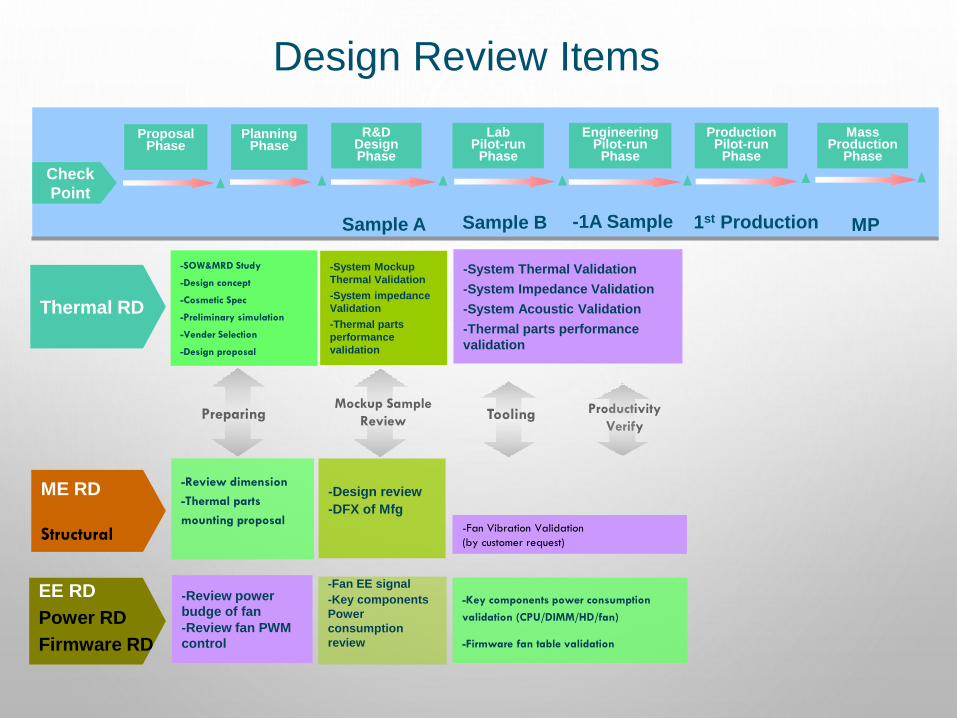
-Review dimension
-Thermal parts
mounting proposal
ME RD
Structural
-Design review
-DFX of Mfg
EE RD
Power RD
Firmware RD
-Review power
budge of fan
-Review fan PWM
control
-Fan EE signal
-Key components
Power
consumption
review
Design Review Items
Check
Point
ProposalPhase
PlanningPhase
R&DDesignPhase
LabPilot-run
Phase
EngineeringPilot-run
Phase
ProductionPilot-run
Phase
MassProduction
Phase
Sample A Sample B 1st Production MP-1A Sample
Thermal RD
-SOW&MRD Study
-Design concept
-Cosmetic Spec
-Preliminary simulation
-Vender Selection
-Design proposal
-System Mockup
Thermal Validation
-System impedance
Validation
-Thermal parts
performance
validation
ToolingMockup Sample
ReviewProductivity
Verify Preparing
-Fan Vibration Validation
(by customer request)
-System Thermal Validation
-System Impedance Validation
-System Acoustic Validation
-Thermal parts performance
validation
-Key components power consumption
validation (CPU/DIMM/HD/fan)
-Firmware fan table validation
MECHANICAL DESIGN PROCESS
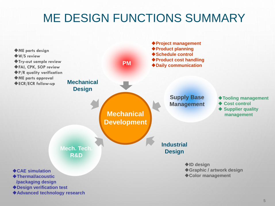
ME DESIGN FUNCTIONS SUMMARY
5
製造
PM
Mechanical
Development
Mechanical
Design
Mech. Tech.
R&D
Industrial
Design
Supply Base
Management
◆ME parts design
◆W/S review
◆Try-out sample review
◆FAI, CPK, SOP review
◆P/R quality verification
◆ME parts approval
◆ECR/ECR follow-up
◆Tooling management
◆ Cost control
◆ Supplier quality
management
◆CAE simulation
◆Thermal/acoustic
/packaging design
◆Design verification test
◆Advanced technology research
◆Project management
◆Product planning
◆Schedule control
◆Product cost handling
◆Daily communication
◆ID design
◆Graphic / artwork design
◆Color management
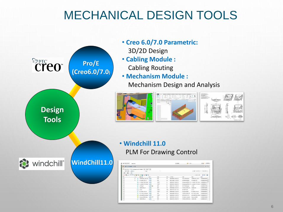
MECHANICAL DESIGN TOOLS
6
• Creo 6.0/7.0 Parametric: 3D/2D Design
• Cabling Module : Cabling Routing
• Mechanism Module : Mechanism Design and Analysis
• Windchill 11.0PLM For Drawing Control
DesignTools
Pro/E(Creo6.0/7.0)
WindChill11.0
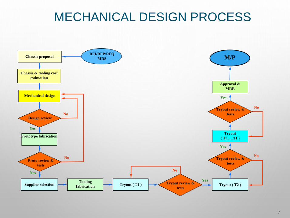
MECHANICAL DESIGN PROCESS
7
Chassis proposal
Mechanical design
Design review
Proto review &
tests
Supplier selection
Chassis & tooling cost
estimation
Yes
Yes
No
No
Tryout ( T1 ) Tryout review &
tests
Yes
Tryout ( T2 )
Tryout
( T3, …Tf )
Approval &
MRR
M/P
Prototype fabrication
Tryout review &
tests
Tooling
fabrication
Tryout review &
tests
No
No
Yes
No
Yes
RFI/RFP/RFQ
MRS

DESIGN QUALITY
8
• TA – Tolerance Analysis• Structure CAE simulation• DFMEA - Design Failure Mode
and Effect Analysis
• ME Design Check List• PCB Design Check List• Form Fit Check (Test Case)• Interference Check
• ME Weekly Review Meeting• Design Review By Function
Team• Design Review Tracking List
• Mockup Sample Review meeting
• ME Part control table
DesignQuality
DesignCheck
DesignReview
SampleReview
DesignAnalysis
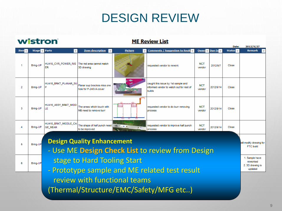
DESIGN REVIEW
9
Design Quality Enhancement
- Use ME Design Check List to review from Design stage to Hard Tooling Start
- Prototype sample and ME related test result review with functional teams
(Thermal/Structure/EMC/Safety/MFG etc..)

TA – TOLERANCE ANALYSIS
10
Optimize ME design , prevent interference
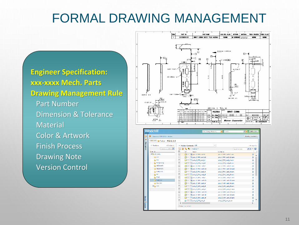
FORMAL DRAWING MANAGEMENT
11
Engineer Specification:
xxx-xxxx Mech. Parts
Drawing Management Rule
Part Number
Dimension & Tolerance
Material
Color & Artwork
Finish Process
Drawing Note
Version Control
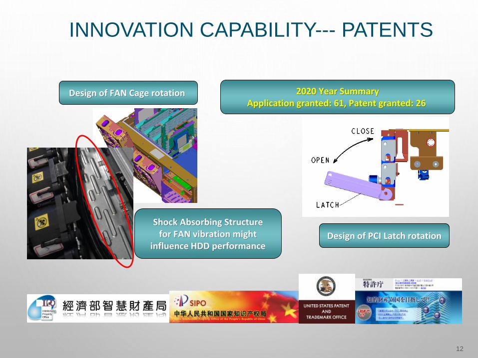
INNOVATION CAPABILITY--- PATENTS
12
Design of FAN Cage rotation
Design of PCI Latch rotation
2020 Year SummaryApplication granted: 61, Patent granted: 26
Shock Absorbing Structurefor FAN vibration might
influence HDD performance

THERMAL/ACOUSTIC DESIGN PROCESS
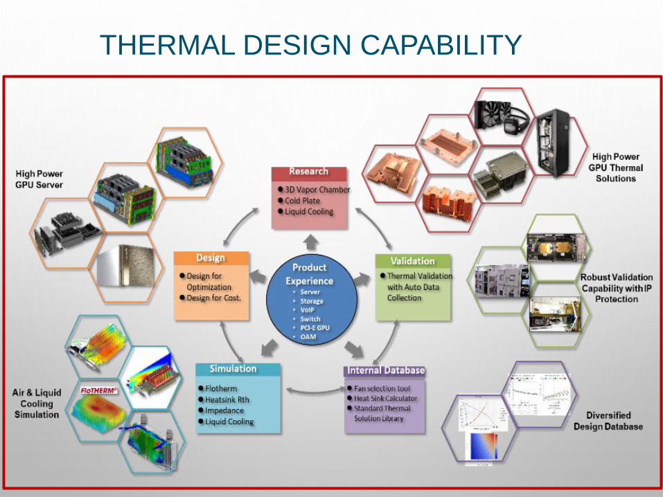
THERMAL DESIGN CAPABILITY
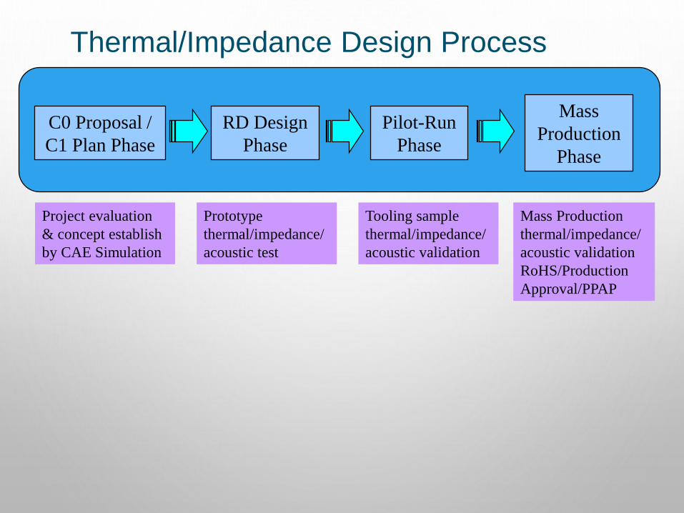
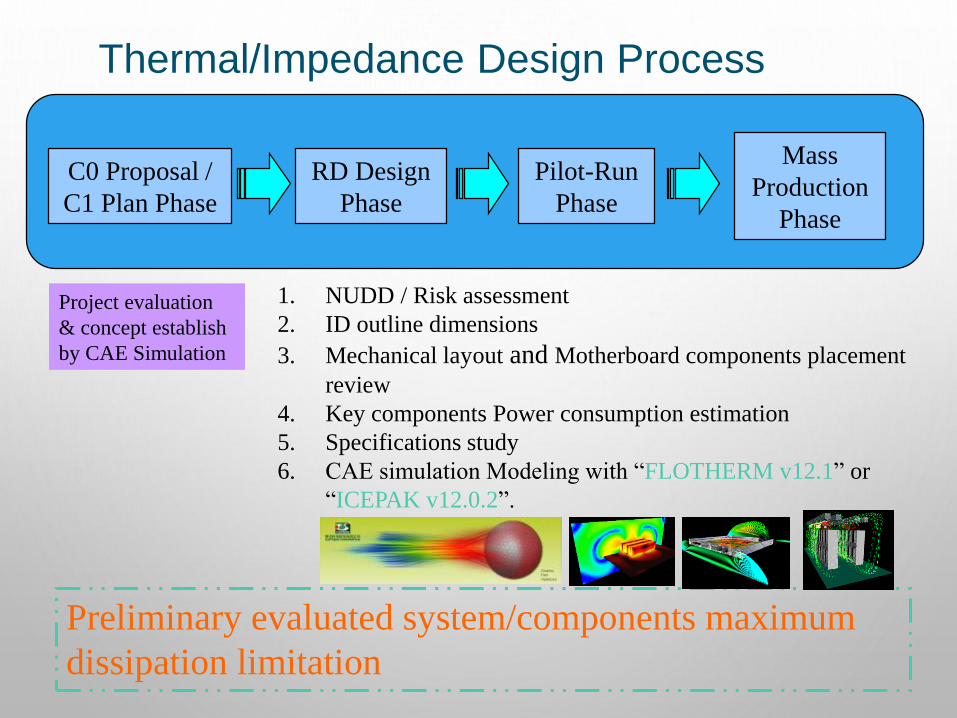
Thermal/Impedance Design Process
C0 Proposal /
C1 Plan Phase
RD Design
Phase
Pilot-Run
Phase
Mass
Production
Phase
Project evaluation
& concept establish
by CAE Simulation
Prototype
thermal/impedance/
acoustic test
Tooling sample
thermal/impedance/
acoustic validation
Mass Production
thermal/impedance/
acoustic validation
RoHS/Production
Approval/PPAP
Thermal/Impedance Design Process
C0 Proposal /
C1 Plan Phase
RD Design
Phase
Pilot-Run
Phase
Mass
Production
Phase
Project evaluation
& concept establish
by CAE Simulation
1. NUDD / Risk assessment
2. ID outline dimensions
3. Mechanical layout and Motherboard components placement
review
4. Key components Power consumption estimation
5. Specifications study
6. CAE simulation Modeling with “FLOTHERM v12.1” or
“ICEPAK v12.0.2”.
Preliminary evaluated system/components maximum
dissipation limitation
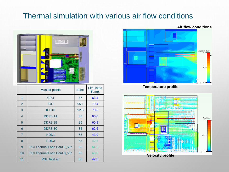
Thermal simulation with various air flow conditions
Air flow conditions
Temperature profile
Velocity profile
Monitor points Spec.Simulated
Temp.
1 CPU 67 63.4
2 IOH 95.1 79.4
3 ICH10 92.5 70.6
4 DDR3-1A 85 60.6
5 DDR3-2B 85 60.8
6 DDR3-3C 85 62.6
7 HDD1 55 43.9
8 HDD3 55 42.6
9 PCI Thermal Load Card 1_VR 95 64.2
10 PCI Thermal Load Card 3_VR 95 65.8
11 PSU Inlet air 50 42.3

Thermal/Impedance Design Process
Proposal/Plan
Phase
C2 RD
Design
Phase
Pilot-Run
Phase
Mass
Production
Phase
Prototype
thermal/impedance/
acoustic test
1. Prototype Chassis
2. Prototype motherboard with key
components TTV
3. Sampling heat-sink module and
flow generator choice by thermal
simulation results
4. Thermal/Acoustic/Impedance
validation and optimum
Develop optimum fan / heat-sink choice and make sure
cooling module system’s dissipated capability
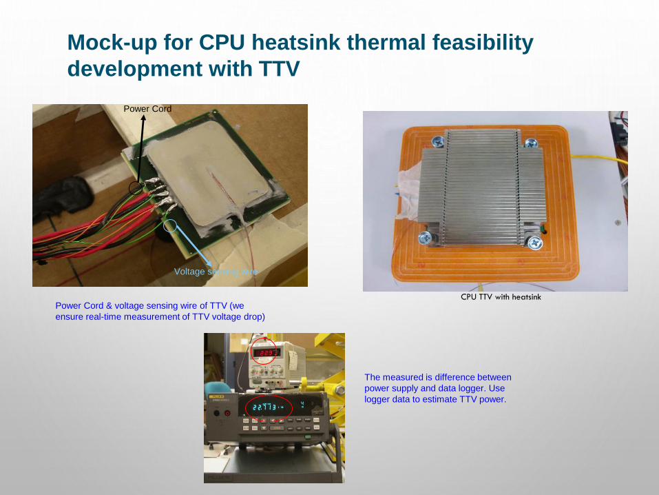
Mock-up for CPU heatsink thermal feasibility
development with TTV
Power Cord & voltage sensing wire of TTV (we
ensure real-time measurement of TTV voltage drop)
Power Cord
Voltage sensing wire
The measured is difference between
power supply and data logger. Use
logger data to estimate TTV power.
CPU TTV with heatsink
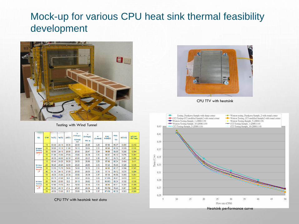
Mock-up for various CPU heat sink thermal feasibility
development
0.25
0.27
0.29
0.31
0.33
0.35
0.37
0.39
0.41
0.43
5 10 15 20 25 30 35 40 45 50
Flow rate (CFM)
The
ta (
℃/w
)
Dell Testing_Furukawa Sample with sharp corner Wistron testing_Furukawa Sample_2 with round cornerCCI Testing-CCI modified Sample2 with round corner Wistron Testing_CCI modified Sample2 with round cornerWistron Testing-Sample_1 (20081119) Wistron Testing-Sample_5 (20081119)Wistron Testing-Sample_10 (20081119) CCI Testing-Sample_1 (20081114)CCI Testing-Sample_5 (20081114) CCI Testing-Sample_10 (20081114)
CPU TTV with heatsink
CPU TTV with heatsink test data
Heatsink performance curve
Testing with Wind Tunnel
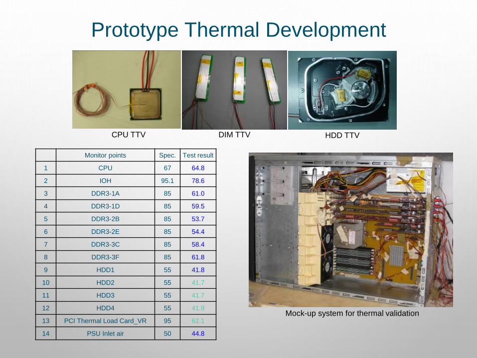
Monitor points Spec. Test result
1 CPU 67 64.8
2 IOH 95.1 78.6
3 DDR3-1A 85 61.0
4 DDR3-1D 85 59.5
5 DDR3-2B 85 53.7
6 DDR3-2E 85 54.4
7 DDR3-3C 85 58.4
8 DDR3-3F 85 61.8
9 HDD1 55 41.8
10 HDD2 55 41.7
11 HDD3 55 41.7
12 HDD4 55 41.9
13 PCI Thermal Load Card_VR 95 62.1
14 PSU Inlet air 50 44.8
HDD TTVDIM TTVCPU TTV
Mock-up system for thermal validation
Prototype Thermal Development
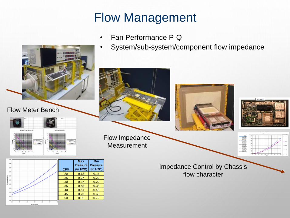
Flow Management
Flow Meter Bench
Flow Impedance
Measurement
Impedance Control by Chassis
flow characterCFM
Max
Pressure
(in H2O)
Min
Pressure
(in H2O)
20 0.18 0.14
25 0.27 0.22
30 0.37 0.29
35 0.48 0.38
40 0.61 0.48
45 0.75 0.60
50 0.92 0.72
• Fan Performance P-Q
• System/sub-system/component flow impedance
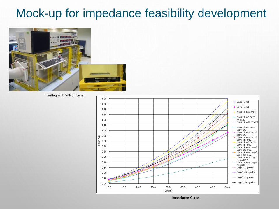
Mock-up for impedance feasibility development
0.00
0.10
0.20
0.30
0.40
0.50
0.60
0.70
0.80
0.90
1.00
1.10
1.20
1.30
1.40
1.50
1.60
10.0 15.0 20.0 25.0 30.0 35.0 40.0 45.0 50.0
Q(cfm)
Ps(i
n A
q)
Upper Limit
Lower Limit
pitch 1.6 no gesket
pitch 1.6 old bezel
no HDDpitch 1.6 with gesket
pitch 1.6 old bezel
with HDDpitch 1.6 new bezel
with HDDpitch 1.6 new bezel
with HDD traypitch 1.6 old bezel
with HDD traypitch 1.6 new cage1
with HDD traypitch 1.6 new cage2
with HDD traypitch 1.6 new cage1
origin HDDpitch 1.6 new cage2
origin HDDcage1 no gasket
cage1 with gasket
cage2 no gasket
cage2 with gasket
Testing with Wind Tunnel
Impedance Curve
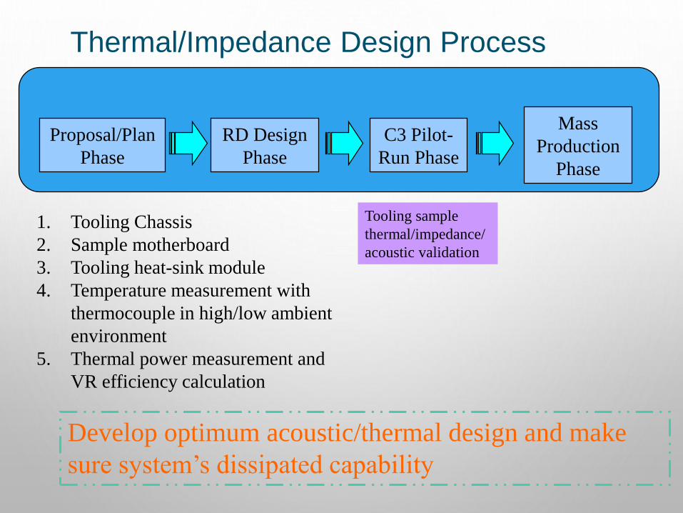
Proposal/Plan
Phase
RD Design
Phase
C3 Pilot-
Run Phase
Mass
Production
Phase
Tooling sample
thermal/impedance/
acoustic validation
1. Tooling Chassis
2. Sample motherboard
3. Tooling heat-sink module
4. Temperature measurement with
thermocouple in high/low ambient
environment
5. Thermal power measurement and
VR efficiency calculation
Develop optimum acoustic/thermal design and make
sure system’s dissipated capability
Thermal/Impedance Design Process
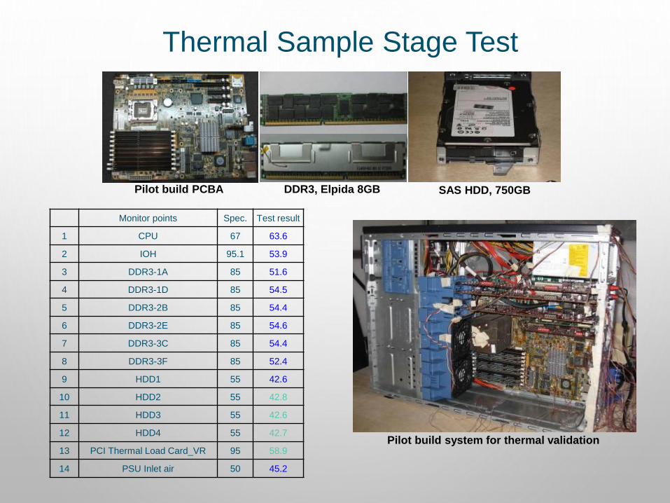
Thermal Sample Stage Test
Monitor points Spec. Test result
1 CPU 67 63.6
2 IOH 95.1 53.9
3 DDR3-1A 85 51.6
4 DDR3-1D 85 54.5
5 DDR3-2B 85 54.4
6 DDR3-2E 85 54.6
7 DDR3-3C 85 54.4
8 DDR3-3F 85 52.4
9 HDD1 55 42.6
10 HDD2 55 42.8
11 HDD3 55 42.6
12 HDD4 55 42.7
13 PCI Thermal Load Card_VR 95 58.9
14 PSU Inlet air 50 45.2
Pilot build system for thermal validation
Pilot build PCBA SAS HDD, 750GBDDR3, Elpida 8GB
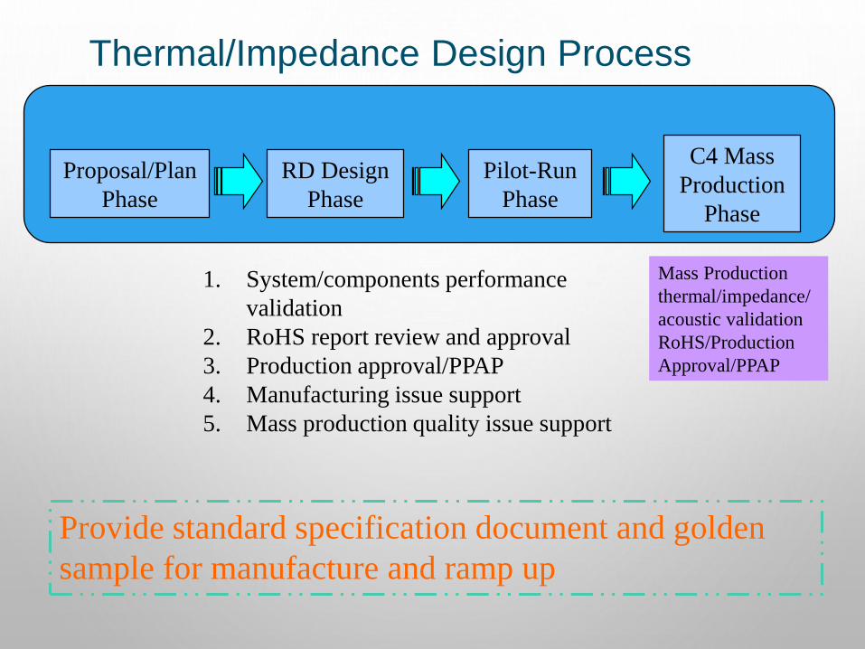
Proposal/Plan
Phase
RD Design
Phase
Pilot-Run
Phase
C4 Mass
Production
Phase
Mass Production
thermal/impedance/
acoustic validation
RoHS/Production
Approval/PPAP
1. System/components performance
validation
2. RoHS report review and approval
3. Production approval/PPAP
4. Manufacturing issue support
5. Mass production quality issue support
Provide standard specification document and golden
sample for manufacture and ramp up
Thermal/Impedance Design Process

Thermal Parts Approval
Passive Heat sinkAir-baffle
FAI
RoHS
Performance

ACOUSTIC DESIGN
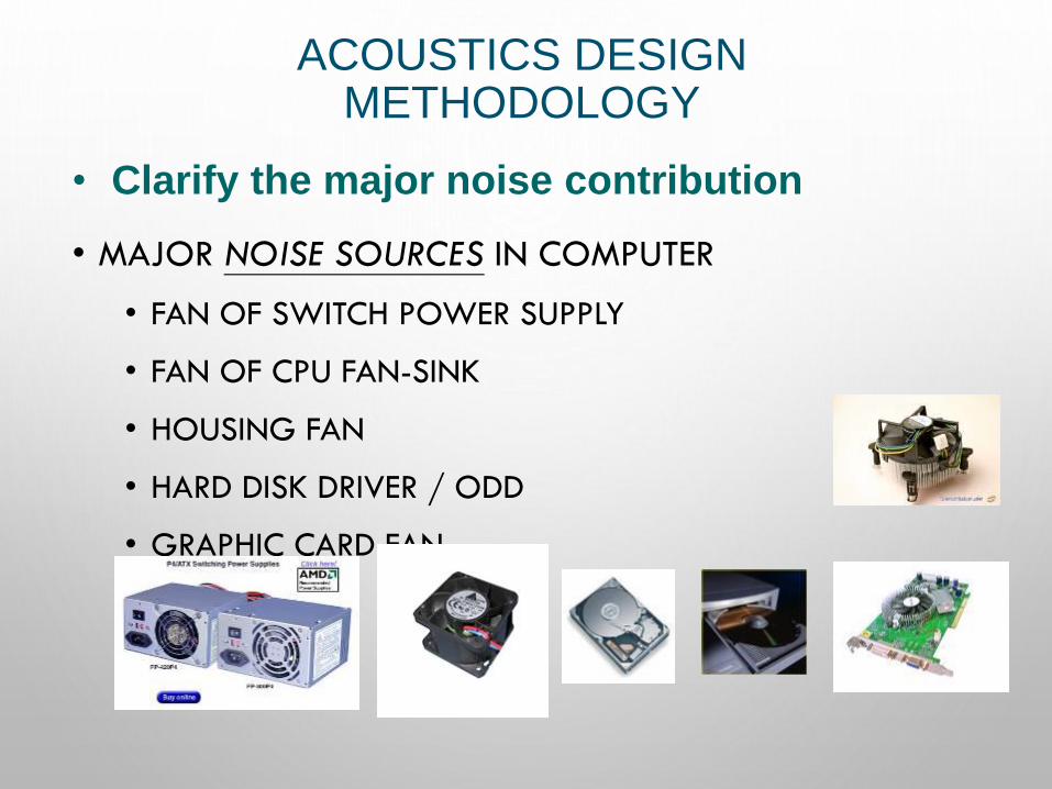
ACOUSTICS DESIGN METHODOLOGY
• MAJOR NOISE SOURCES IN COMPUTER
• FAN OF SWITCH POWER SUPPLY
• FAN OF CPU FAN-SINK
• HOUSING FAN
• HARD DISK DRIVER / ODD
• GRAPHIC CARD FAN
• Clarify the major noise contribution
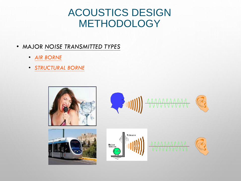
ACOUSTICS DESIGN METHODOLOGY
• MAJOR NOISE TRANSMITTED TYPES
• AIR BORNE
• STRUCTURAL BORNE
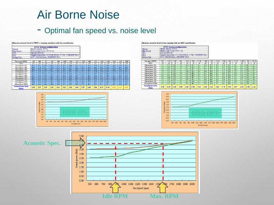
Air Borne Noise
- Optimal fan speed vs. noise level
Idle RPM Max. RPM
Acoustic Spec.
HDD ON HDD OFF
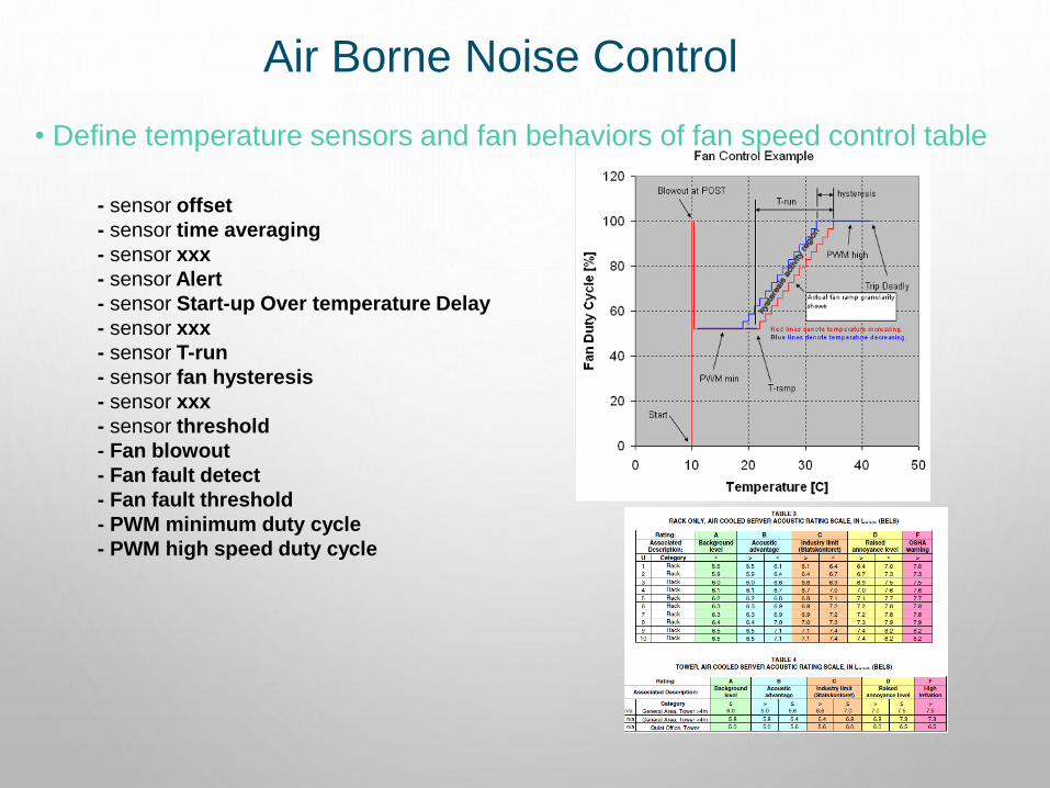
Air Borne Noise Control
• Define temperature sensors and fan behaviors of fan speed control table
- sensor offset
- sensor time averaging
- sensor xxx
- sensor Alert
- sensor Start-up Over temperature Delay
- sensor xxx
- sensor T-run
- sensor fan hysteresis
- sensor xxx
- sensor threshold
- Fan blowout
- Fan fault detect
- Fan fault threshold
- PWM minimum duty cycle
- PWM high speed duty cycle
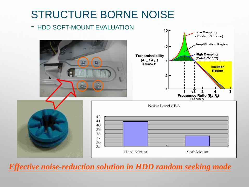
Effective noise-reduction solution in HDD random seeking mode
Noise Level dBA
35363738
39404142
Hard Mount Soft Mount
STRUCTURE BORNE NOISE- HDD SOFT-MOUNT EVALUATION
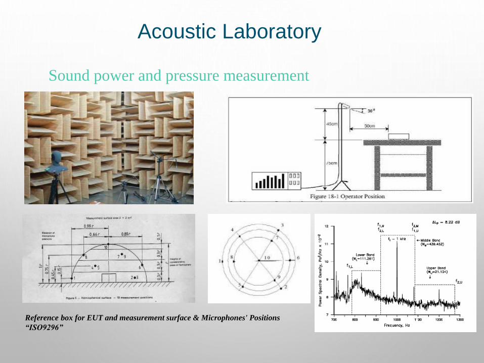
Acoustic Laboratory
Reference box for EUT and measurement surface & Microphones' Positions
“ISO9296”
Sound power and pressure measurement
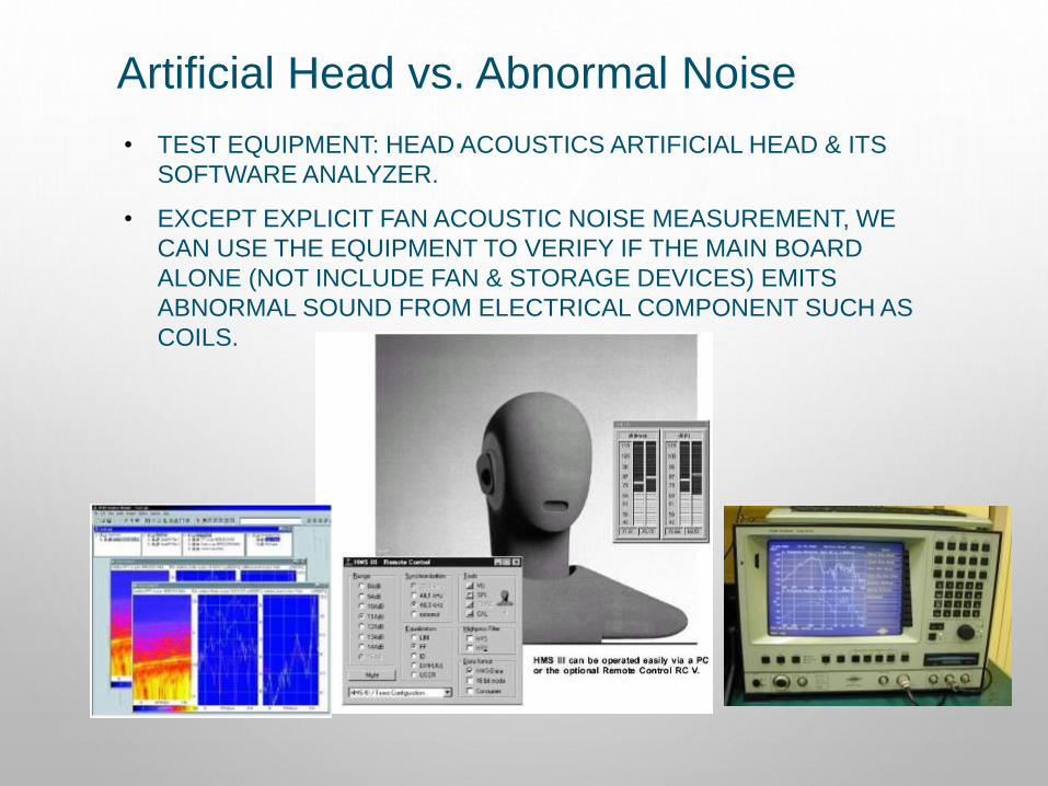
Artificial Head vs. Abnormal Noise
• TEST EQUIPMENT: HEAD ACOUSTICS ARTIFICIAL HEAD & ITS
SOFTWARE ANALYZER.
• EXCEPT EXPLICIT FAN ACOUSTIC NOISE MEASUREMENT, WE
CAN USE THE EQUIPMENT TO VERIFY IF THE MAIN BOARD
ALONE (NOT INCLUDE FAN & STORAGE DEVICES) EMITS
ABNORMAL SOUND FROM ELECTRICAL COMPONENT SUCH AS
COILS.

STRUCTURE DESIGN
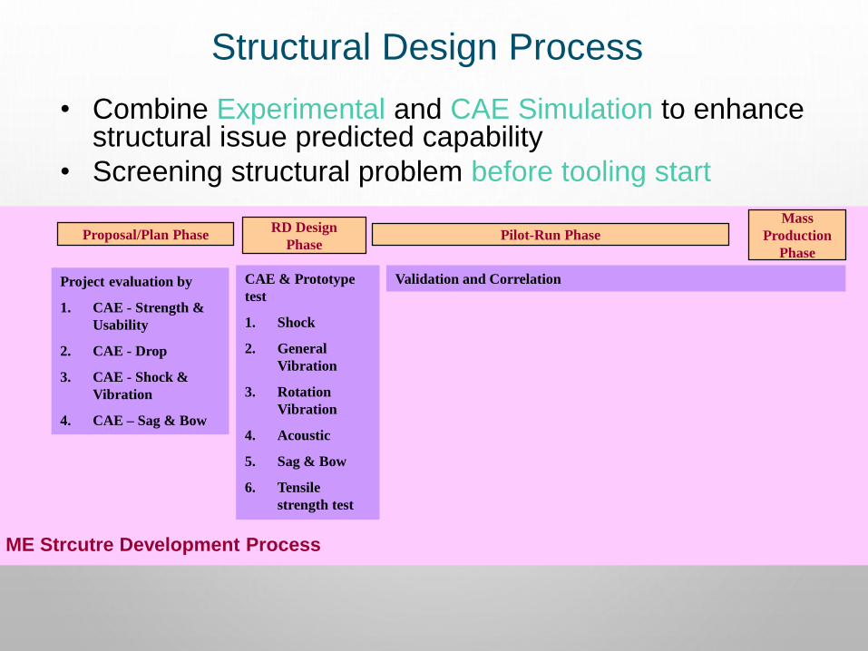
Structural Design Process
• Combine Experimental and CAE Simulation to enhance structural issue predicted capability
• Screening structural problem before tooling start
Proposal/Plan PhaseRD Design
PhasePilot-Run Phase
Mass
Production
Phase
Project evaluation by
1. CAE - Strength &
Usability
2. CAE - Drop
3. CAE - Shock &
Vibration
4. CAE – Sag & Bow
CAE & Prototype
test
1. Shock
2. General
Vibration
3. Rotation
Vibration
4. Acoustic
5. Sag & Bow
6. Tensile
strength test
Validation and Correlation
ME Strcutre Development Process
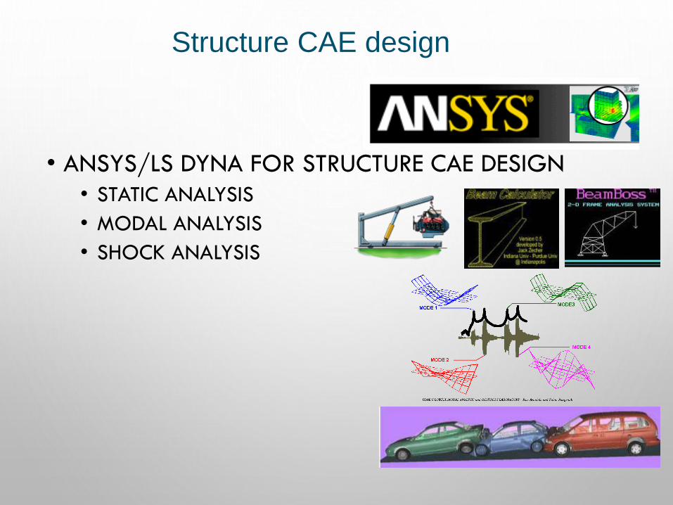
Structure CAE design
• ANSYS/LS DYNA FOR STRUCTURE CAE DESIGN
• STATIC ANALYSIS
• MODAL ANALYSIS
• SHOCK ANALYSIS
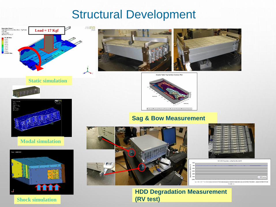
Structural Development
Sag & Bow Measurement
900
800
700
600
500
400
300
200
100
0
050
100150
200250
300350
450
-3.00-2.50-2.00-1.50-1.00-0.500.000.501.00
Depth (mm)
Width (mm)
Granite Table Top Surface Contour Plot
-3.00--2.50 -2.50--2.00 -2.00--1.50 -1.50--1.00 -1.00--0.50 -0.50-0.00 0.00-0.50 0.50-1.00
HDD Degradation Measurement
(RV test)
Load = 17 Kgf
Static simulation
Modal simulation
Shock simulation
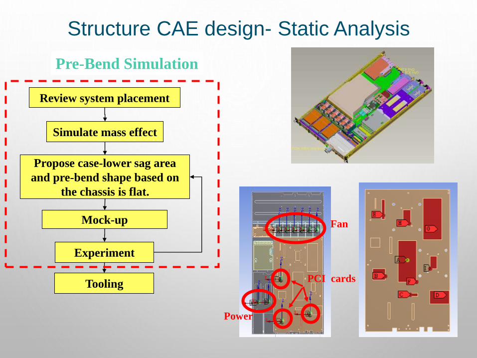
Structure CAE design- Static Analysis
Pre-Bend Simulation
Review system placement
Propose case-lower sag area
and pre-bend shape based on
the chassis is flat.
Simulate mass effect
Mock-up
Experiment
Tooling
Fan
Power
PCI cards
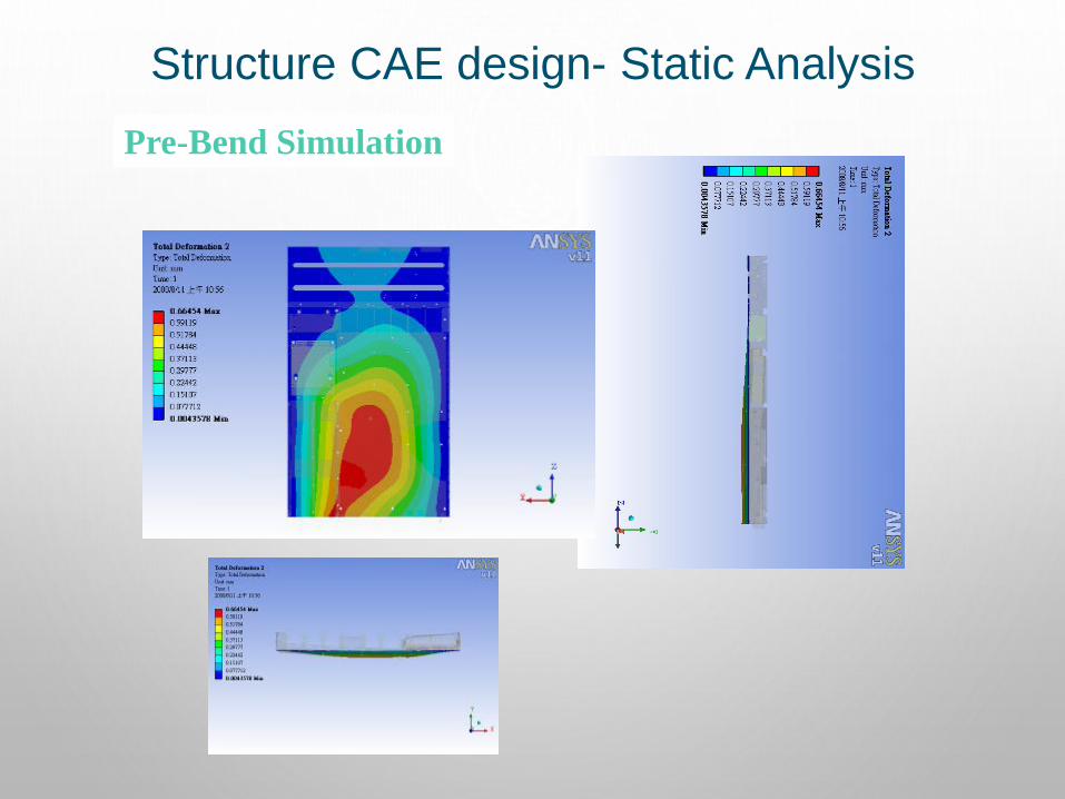
Structure CAE design- Static Analysis
Pre-Bend Simulation
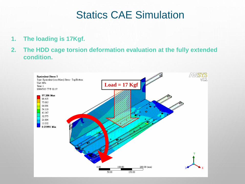
Statics CAE Simulation
1. The loading is 17Kgf.
2. The HDD cage torsion deformation evaluation at the fully extended
condition.
Load = 17 Kgf
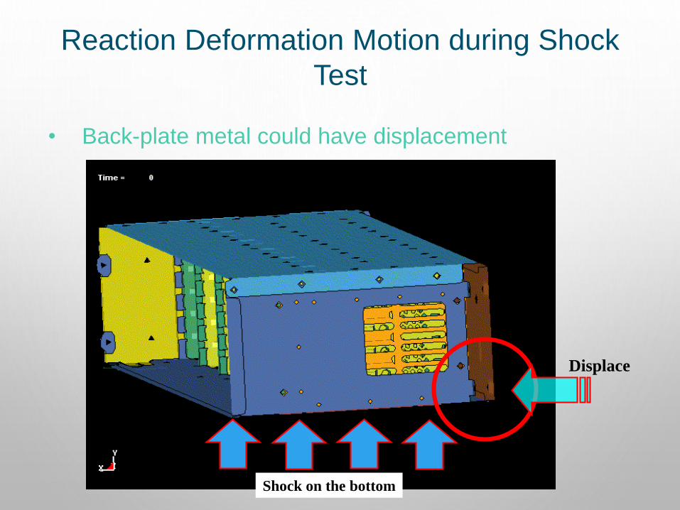
Reaction Deformation Motion during Shock
Test
• Back-plate metal could have displacement
Displace
Shock on the bottom
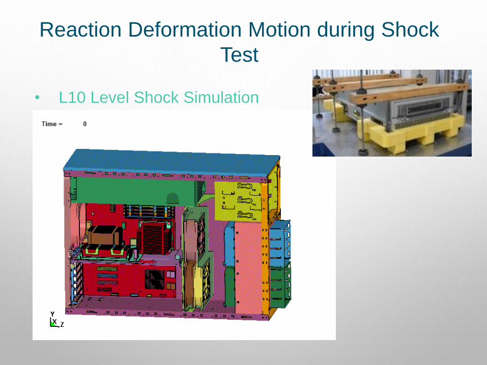
Reaction Deformation Motion during Shock
Test
• L10 Level Shock Simulation
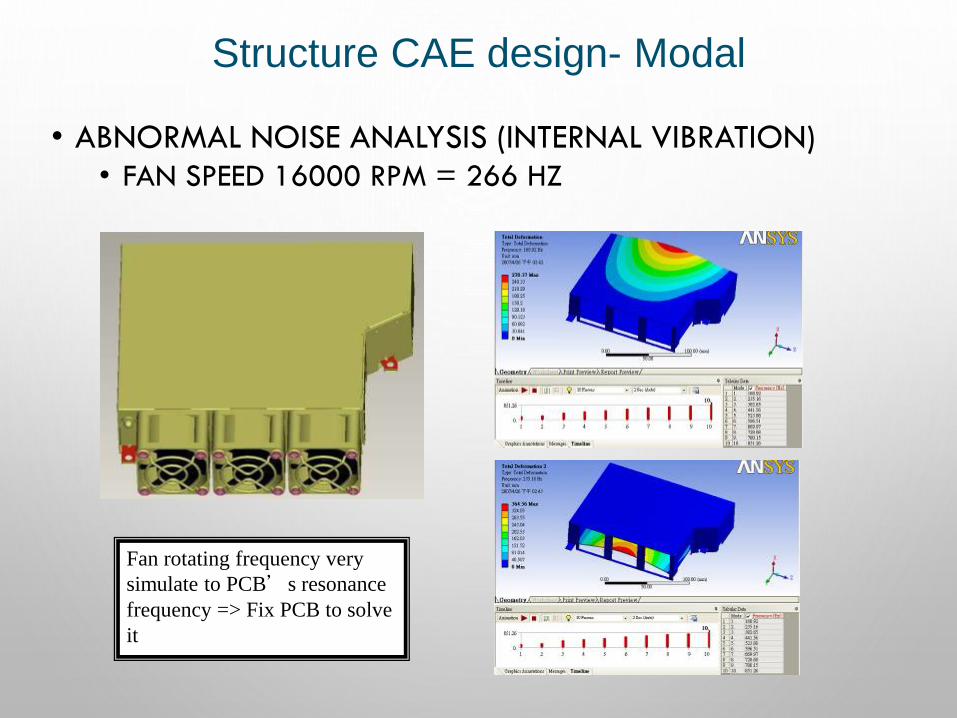
• ABNORMAL NOISE ANALYSIS (INTERNAL VIBRATION)• FAN SPEED 16000 RPM = 266 HZ
Structure CAE design- Modal
Fan rotating frequency very
simulate to PCB’s resonance
frequency => Fix PCB to solve
it

Structure CAE design- Shock
Square Wave
This area will deform very seriously cause
PSU follow the response. Need to improve
the cutting section stiffness.
• SHOCK CAUSES PSU BRACKET DEFORMED• ENHANCE SIDE CHASSIS CASE STRENGTH
The same deformation location
between CAE and experiment
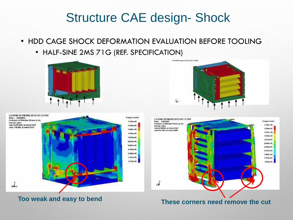
Structure CAE design- Shock
• HDD CAGE SHOCK DEFORMATION EVALUATION BEFORE TOOLING
• HALF-SINE 2MS 71G (REF. SPECIFICATION)
Too weak and easy to bendThese corners need remove the cut
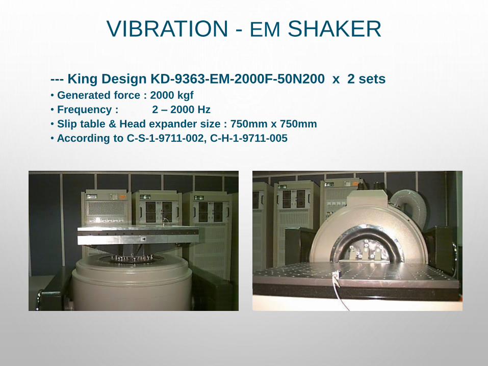
VIBRATION - EM SHAKER
--- King Design KD-9363-EM-2000F-50N200 x 2 sets• Generated force : 2000 kgf
• Frequency : 2 – 2000 Hz
• Slip table & Head expander size : 750mm x 750mm
• According to C-S-1-9711-002, C-H-1-9711-005
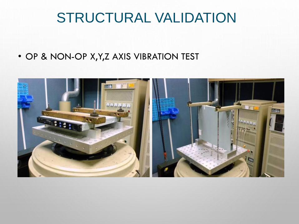
STRUCTURAL VALIDATION
• OP & NON-OP X,Y,Z AXIS VIBRATION TEST
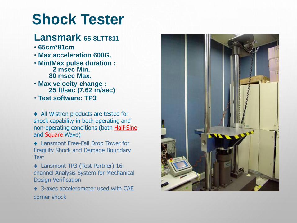
Shock TesterLansmark 65-8LTT811
• 65cm*81cm
• Max acceleration 600G.
• Min/Max pulse duration :2 msec Min.
80 msec Max.
• Max velocity change :25 ft/sec (7.62 m/sec)
• Test software: TP3
⧫ All Wistron products are tested for shock capability in both operating and non-operating conditions (both Half-Sineand Square Wave)
⧫ Lansmont Free-Fall Drop Tower for Fragility Shock and Damage Boundary Test
⧫ Lansmont TP3 (Test Partner) 16-channel Analysis System for Mechanical Design Verification
⧫ 3-axes accelerometer used with CAE
corner shock
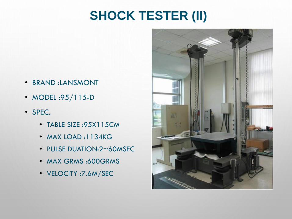
SHOCK TESTER (II)
• BRAND :LANSMONT
• MODEL :95/115-D
• SPEC.
• TABLE SIZE :95X115CM
• MAX LOAD :1134KG
• PULSE DUATION:2~60MSEC
• MAX GRMS :600GRMS
• VELOCITY :7.6M/SEC
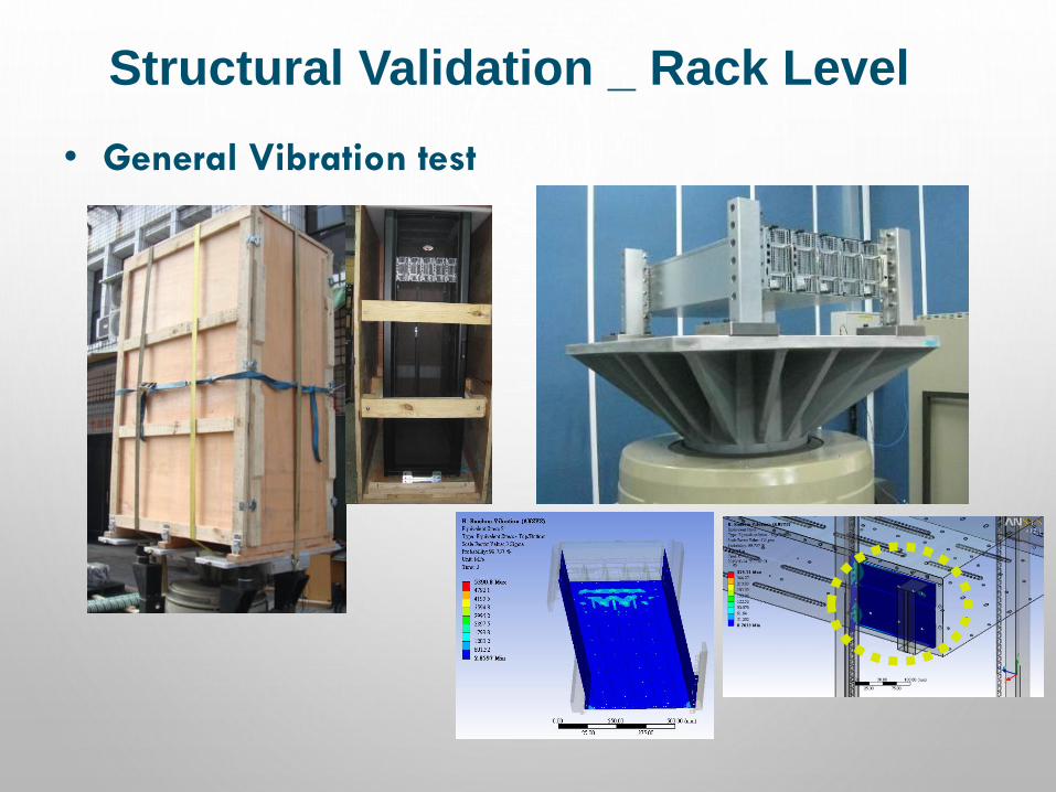
Structural Validation _ Rack Level
• General Vibration test

PACKAGE DESIGN
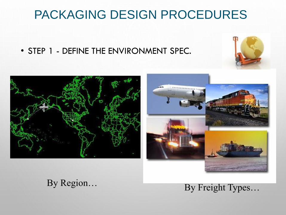
PACKAGING DESIGN PROCEDURES
• STEP 1 - DEFINE THE ENVIRONMENT SPEC.
By Region…By Freight Types…
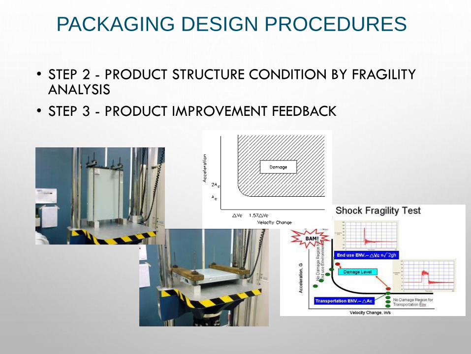
PACKAGING DESIGN PROCEDURES
• STEP 2 - PRODUCT STRUCTURE CONDITION BY FRAGILITY ANALYSIS
• STEP 3 - PRODUCT IMPROVEMENT FEEDBACK
PACKAGING DESIGN PROCEDURES
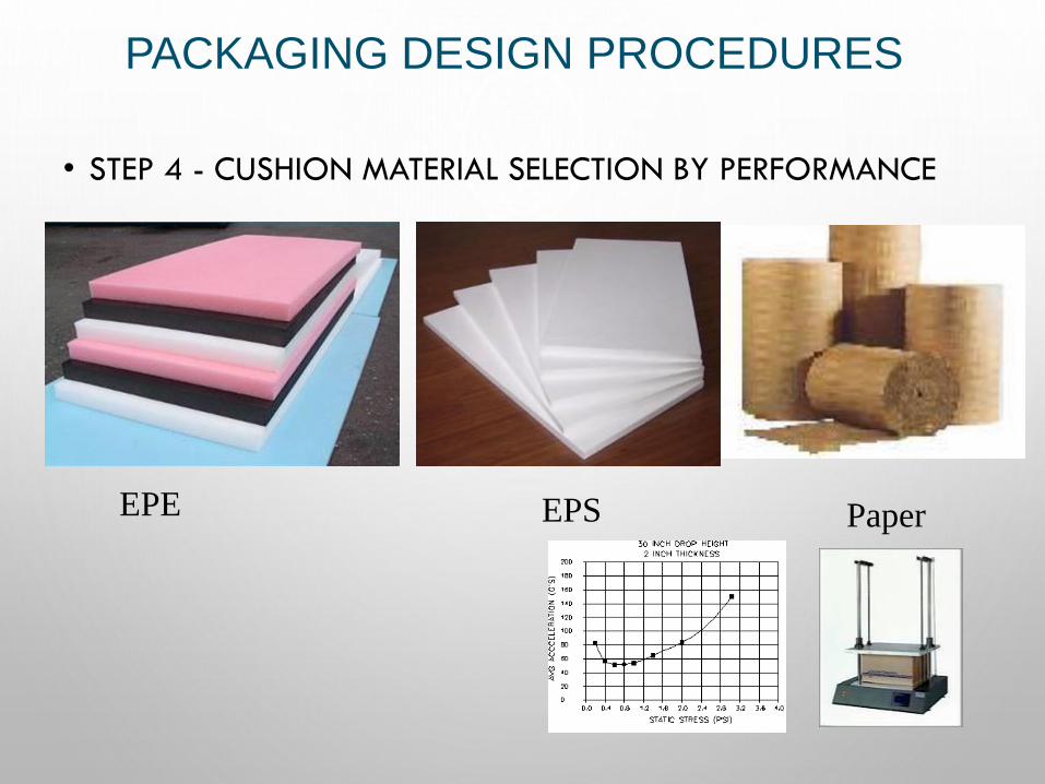
• STEP 4 - CUSHION MATERIAL SELECTION BY PERFORMANCE
EPE EPS Paper
PACKAGING DESIGN PROCEDURES
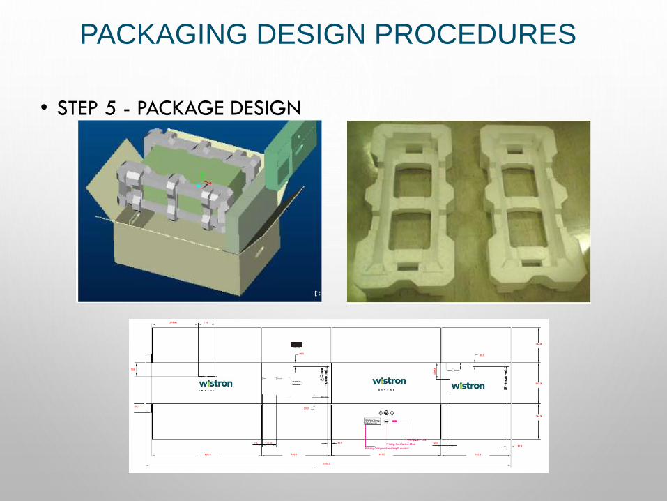
• STEP 5 - PACKAGE DESIGN
PACKAGING DESIGN PROCEDURES
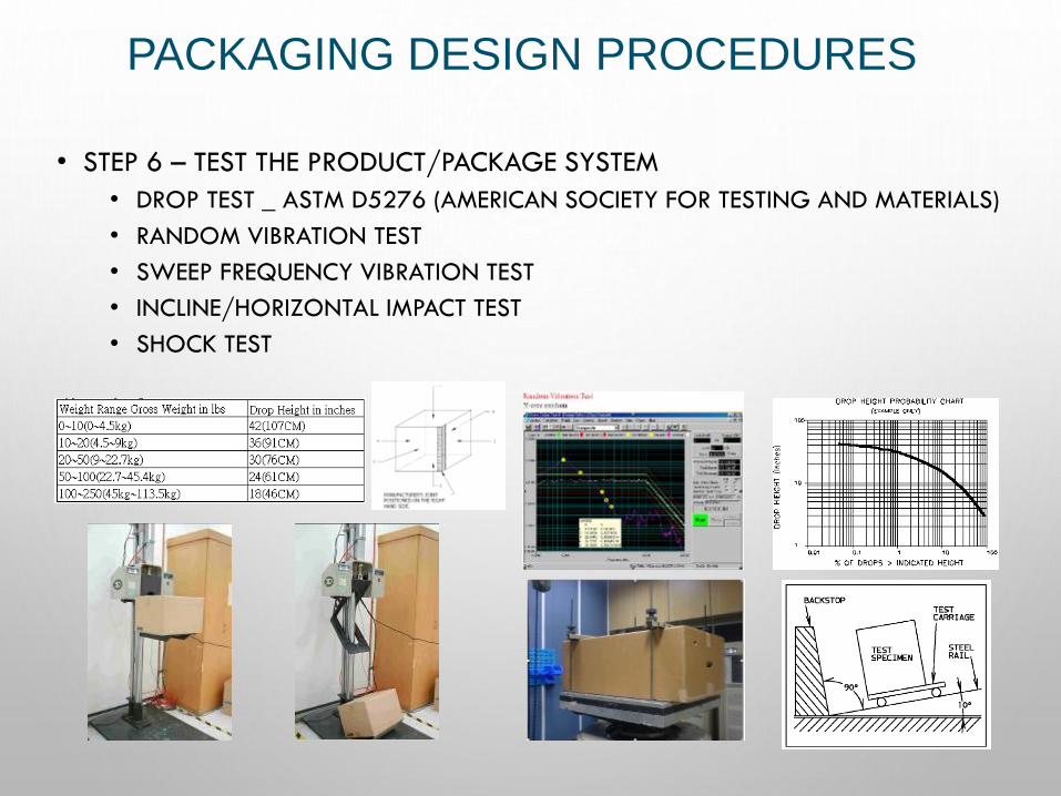
• STEP 6 – TEST THE PRODUCT/PACKAGE SYSTEM
• DROP TEST _ ASTM D5276 (AMERICAN SOCIETY FOR TESTING AND MATERIALS)
• RANDOM VIBRATION TEST
• SWEEP FREQUENCY VIBRATION TEST
• INCLINE/HORIZONTAL IMPACT TEST
• SHOCK TEST
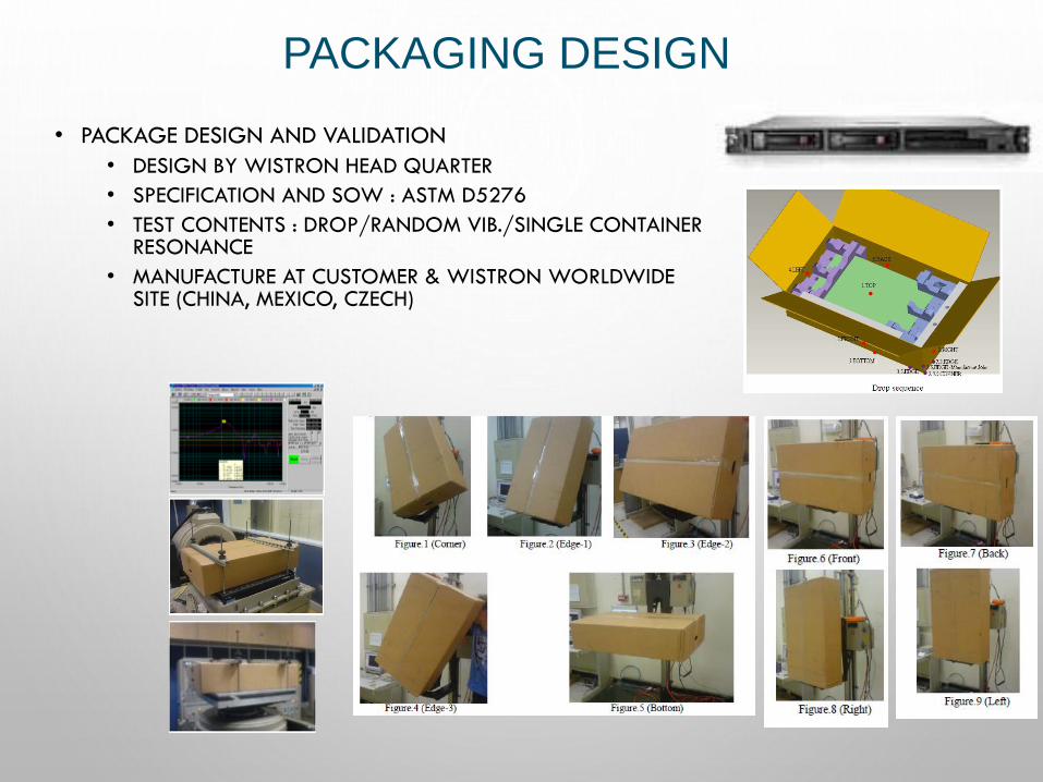
PACKAGING DESIGN
• PACKAGE DESIGN AND VALIDATION
• DESIGN BY WISTRON HEAD QUARTER
• SPECIFICATION AND SOW : ASTM D5276
• TEST CONTENTS : DROP/RANDOM VIB./SINGLE CONTAINER RESONANCE
• MANUFACTURE AT CUSTOMER & WISTRON WORLDWIDE SITE (CHINA, MEXICO, CZECH)
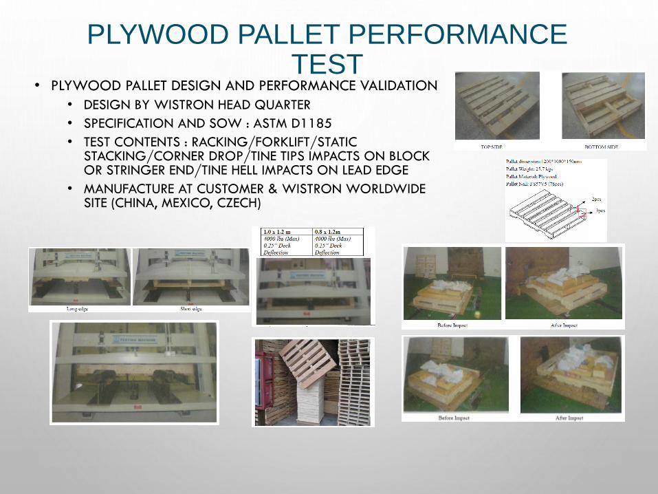
PLYWOOD PALLET PERFORMANCE TEST
• PLYWOOD PALLET DESIGN AND PERFORMANCE VALIDATION
• DESIGN BY WISTRON HEAD QUARTER
• SPECIFICATION AND SOW : ASTM D1185
• TEST CONTENTS : RACKING/FORKLIFT/STATIC STACKING/CORNER DROP/TINE TIPS IMPACTS ON BLOCK OR STRINGER END/TINE HELL IMPACTS ON LEAD EDGE
• MANUFACTURE AT CUSTOMER & WISTRON WORLDWIDE SITE (CHINA, MEXICO, CZECH)
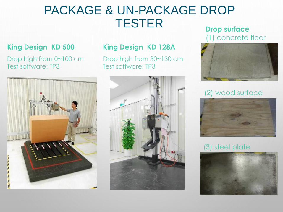
PACKAGE & UN-PACKAGE DROP TESTER
King Design KD 500
Drop high from 0~100 cm
Test software: TP3
Drop surface
(1) concrete floor
(2) wood surface
(3) steel plate
King Design KD 128A
Drop high from 30~130 cm
Test software: TP3

THANK YOU.