serveriron adx graphical user interface guide · the following brocade documents supplement the...
TRANSCRIPT

53-1001440-0115 May 09
®
ServerIron ADXGraphical User Interface Guide
Supporting ServerIron ADX 1000, ServerIron ADX 4000 and ServerIron ADX 8000

Copyright © 2009 Brocade Communications Systems, Inc. All Rights Reserved.
Brocade, the B-wing symbol, BigIron, DCX, Fabric OS, FastIron, IronPoint, IronShield, IronView, IronWare, JetCore, NetIron, SecureIron, ServerIron, StorageX, and TurboIron are registered trademarks, and DCFM, Extraordinary Networks, and SAN Health are trademarks of Brocade Communications Systems, Inc., in the United States and/or in other countries. All other brands, products, or service names are or may be trademarks or service marks of, and are used to identify, products or services of their respective owners.
Notice: This document is for informational purposes only and does not set forth any warranty, expressed or implied, concerning any equipment, equipment feature, or service offered or to be offered by Brocade. Brocade reserves the right to make changes to this document at any time, without notice, and assumes no responsibility for its use. This informational document describes features that may not be currently available. Contact a Brocade sales office for information on feature and product availability. Export of technical data contained in this document may require an export license from the United States government.
The authors and Brocade Communications Systems, Inc. shall have no liability or responsibility to any person or entity with respect to any loss, cost, liability, or damages arising from the information contained in this book or the computer programs that accompany it.
The product described by this document may contain “open source” software covered by the GNU General Public License or other open source license agreements. To find-out which open source software is included in Brocade products, view the licensing terms applicable to the open source software, and obtain a copy of the programming source code, please visit http://www.brocade.com/support/oscd.
Brocade Communications Systems, Incorporated
Document History
Corporate and Latin American HeadquartersBrocade Communications Systems, Inc.1745 Technology Drive San Jose, CA 95110 Tel: 1-408-333-8000 Fax: 1-408-333-8101 E-mail: [email protected]
Asia-Pacific HeadquartersBrocade Communications Systems China HK, Ltd.No. 1 Guanghua RoadChao Yang DistrictUnits 2718 and 2818Beijing 100020, ChinaTel: +8610 6588 8888Fax: +8610 6588 9999E-mail: [email protected]
European HeadquartersBrocade Communications Switzerland SàrlCentre SwissairTour B - 4ème étage29, Route de l'AéroportCase Postale 105CH-1215 Genève 15Switzerland Tel: +41 22 799 5640Fax: +41 22 799 5641E-mail: [email protected]
Asia-Pacific HeadquartersBrocade Communications Systems Co., Ltd. (Shenzhen WFOE)Citic PlazaNo. 233 Tian He Road NorthUnit 1308 – 13th FloorGuangzhou, ChinaTel: +8620 3891 2000Fax: +8620 3891 2111E-mail: [email protected]
Title Publication number Summary of changes Date
ServerIron ADX Graphical User Interface Guide
53-1001440-01 New document May 2009

Contents
About This Document
In this chapter . . . . . . . . . . . . . . . . . . . . . . . . . . . . . . . . . . . . . . . . . . . vii
Audience . . . . . . . . . . . . . . . . . . . . . . . . . . . . . . . . . . . . . . . . . . . . . . . vii
Supported hardware and software . . . . . . . . . . . . . . . . . . . . . . . . . . vii
Document conventions. . . . . . . . . . . . . . . . . . . . . . . . . . . . . . . . . . . . viiText formatting . . . . . . . . . . . . . . . . . . . . . . . . . . . . . . . . . . . . . . . viiiNotes, cautions, and danger notices . . . . . . . . . . . . . . . . . . . . . viii
Notice to the reader . . . . . . . . . . . . . . . . . . . . . . . . . . . . . . . . . . . . . . viii
Related publications . . . . . . . . . . . . . . . . . . . . . . . . . . . . . . . . . . . . . . . ix
Getting technical help or reporting errors . . . . . . . . . . . . . . . . . . . . . . ixWeb access . . . . . . . . . . . . . . . . . . . . . . . . . . . . . . . . . . . . . . . . . . ixE-mail access . . . . . . . . . . . . . . . . . . . . . . . . . . . . . . . . . . . . . . . . . ixTelephone access . . . . . . . . . . . . . . . . . . . . . . . . . . . . . . . . . . . . . x
Chapter 1 Getting Started with the GUI
In this chapter . . . . . . . . . . . . . . . . . . . . . . . . . . . . . . . . . . . . . . . . . . . . 1
The ServerIron ADX GUI . . . . . . . . . . . . . . . . . . . . . . . . . . . . . . . . . . . . 1
Accessing the GUI through HTTP . . . . . . . . . . . . . . . . . . . . . . . . . . . . . 3Step 1: Connect to the switch . . . . . . . . . . . . . . . . . . . . . . . . . . . . 3Step 2a: Log in with switch code . . . . . . . . . . . . . . . . . . . . . . . . . 3Step 2b: Log in with router code . . . . . . . . . . . . . . . . . . . . . . . . . . 3Step 3: Connect ServerIron to network . . . . . . . . . . . . . . . . . . . . 4Step 4: Open a browser (IE or FireFox) . . . . . . . . . . . . . . . . . . . . . 4
Accessing the GUI through HTTPS . . . . . . . . . . . . . . . . . . . . . . . . . . . . 6Step 1: Connect to the switch . . . . . . . . . . . . . . . . . . . . . . . . . . . . 6Step 2 . . . . . . . . . . . . . . . . . . . . . . . . . . . . . . . . . . . . . . . . . . . . . . . 6Step 3: SSL configuration . . . . . . . . . . . . . . . . . . . . . . . . . . . . . . . 7Step 4: Enabling HTTPS. . . . . . . . . . . . . . . . . . . . . . . . . . . . . . . . . 8Step 5: Connect ServerIron to network . . . . . . . . . . . . . . . . . . . . 8Step 6: Open a browser . . . . . . . . . . . . . . . . . . . . . . . . . . . . . . . . . 8
Configuring IP addresses . . . . . . . . . . . . . . . . . . . . . . . . . . . . . . . . . .12Configuring an IP address on switch code . . . . . . . . . . . . . . . . .12Configuring an IP address on router code . . . . . . . . . . . . . . . . .13
Configuring Source IP addresses . . . . . . . . . . . . . . . . . . . . . . . . . . . .13Configuring Source IP, Source NAT IP and Source Standby IPon switch code . . . . . . . . . . . . . . . . . . . . . . . . . . . . . . . . . . . . . . .13Configuring Source IP addresses on router code . . . . . . . . . . . 16
Displaying the Dashboard. . . . . . . . . . . . . . . . . . . . . . . . . . . . . . . . . . 17
ServerIron ADX Graphical User Interface Guide iii53-1001440-01

Displaying the Front Panel . . . . . . . . . . . . . . . . . . . . . . . . . . . . . . . . .18
Defining Global System settings . . . . . . . . . . . . . . . . . . . . . . . . . . . .18
Displaying and saving the running configuration . . . . . . . . . . . . . . .19
Chapter 2 Configuring a Real Server and a Real Server Port
In this chapter . . . . . . . . . . . . . . . . . . . . . . . . . . . . . . . . . . . . . . . . . . . 21
Create a basic real server. . . . . . . . . . . . . . . . . . . . . . . . . . . . . . . . . . 21
Create a real server port. . . . . . . . . . . . . . . . . . . . . . . . . . . . . . . . . . .22
Enabling and disabling real server. . . . . . . . . . . . . . . . . . . . . . . . . . .23Enable at Summary tab. . . . . . . . . . . . . . . . . . . . . . . . . . . . . . . .23Disable at Summary tab . . . . . . . . . . . . . . . . . . . . . . . . . . . . . . . 24Enable at Basic tab . . . . . . . . . . . . . . . . . . . . . . . . . . . . . . . . . . . 24Disable at Basic tab. . . . . . . . . . . . . . . . . . . . . . . . . . . . . . . . . . .25
Enabling and disabling real server port. . . . . . . . . . . . . . . . . . . . . . .25Enable at Summary tab. . . . . . . . . . . . . . . . . . . . . . . . . . . . . . . .26Disable at Summary tab . . . . . . . . . . . . . . . . . . . . . . . . . . . . . . . 27Enable at Port tab . . . . . . . . . . . . . . . . . . . . . . . . . . . . . . . . . . . . 27Disable at Port tab . . . . . . . . . . . . . . . . . . . . . . . . . . . . . . . . . . . .28
Cloning a real server . . . . . . . . . . . . . . . . . . . . . . . . . . . . . . . . . . . . . .28
Defining advanced parameters for real servers . . . . . . . . . . . . . . . .30
Viewing real server summary information. . . . . . . . . . . . . . . . . . . . . 31Real server status indicators . . . . . . . . . . . . . . . . . . . . . . . . . . .32Real server port status indicators . . . . . . . . . . . . . . . . . . . . . . .32Viewing real server summary information . . . . . . . . . . . . . . . . .32
Chapter 3 Configuring a Virtual Server and a Virtual Server Port
In this chapter . . . . . . . . . . . . . . . . . . . . . . . . . . . . . . . . . . . . . . . . . . .35
Create a virtual server . . . . . . . . . . . . . . . . . . . . . . . . . . . . . . . . . . . .35
Create virtual server port . . . . . . . . . . . . . . . . . . . . . . . . . . . . . . . . . .36
Bind the virtual server port. . . . . . . . . . . . . . . . . . . . . . . . . . . . . . . . .38
Enabling or disabling a virtual server . . . . . . . . . . . . . . . . . . . . . . . .39Enable at Summary tab. . . . . . . . . . . . . . . . . . . . . . . . . . . . . . . .39Disable at Summary tab . . . . . . . . . . . . . . . . . . . . . . . . . . . . . . .40Enable at Basic tab . . . . . . . . . . . . . . . . . . . . . . . . . . . . . . . . . . .40Disable at Basic tab. . . . . . . . . . . . . . . . . . . . . . . . . . . . . . . . . . . 41
Enabling or disabling virtual server port . . . . . . . . . . . . . . . . . . . . . . 41Enable at Summary tab. . . . . . . . . . . . . . . . . . . . . . . . . . . . . . . . 41Disable at Summary tab . . . . . . . . . . . . . . . . . . . . . . . . . . . . . . .42Enable at Port tab . . . . . . . . . . . . . . . . . . . . . . . . . . . . . . . . . . . .43Disable at Port tab . . . . . . . . . . . . . . . . . . . . . . . . . . . . . . . . . . . .44
Defining advanced virtual server parameters. . . . . . . . . . . . . . . . . .45
iv ServerIron ADX Graphical User Interface Guide53-1001440-01

Chapter 4 Configuring Health Checks
In this chapter . . . . . . . . . . . . . . . . . . . . . . . . . . . . . . . . . . . . . . . . . . . 47
Configure health check for real server . . . . . . . . . . . . . . . . . . . . . . . 47
Enabling Layer 2-4 health checks . . . . . . . . . . . . . . . . . . . . . . . . . . .50
Disabling Layer 2-4 health checks. . . . . . . . . . . . . . . . . . . . . . . . . . . 51
Create a port profile . . . . . . . . . . . . . . . . . . . . . . . . . . . . . . . . . . . . . . 51
Create a port policy . . . . . . . . . . . . . . . . . . . . . . . . . . . . . . . . . . . . . . .54
Configuring Element health check. . . . . . . . . . . . . . . . . . . . . . . . . . .56Configuring TCP or UDP health check policy . . . . . . . . . . . . . . .56Configuring ICMP health check policy . . . . . . . . . . . . . . . . . . . .58Configuring Boolean health check policy . . . . . . . . . . . . . . . . . .59
Configure a match list policy . . . . . . . . . . . . . . . . . . . . . . . . . . . . . . .60
Chapter 5 Configure VLAN, ACLs, and Routes
In this chapter . . . . . . . . . . . . . . . . . . . . . . . . . . . . . . . . . . . . . . . . . . .63
Configuring VLANs. . . . . . . . . . . . . . . . . . . . . . . . . . . . . . . . . . . . . . . .63Configuring a VLAN on switch code . . . . . . . . . . . . . . . . . . . . . .63Configuring a VLAN on router code. . . . . . . . . . . . . . . . . . . . . . .64
Configuring Standard Access Control List . . . . . . . . . . . . . . . . . . . . .65
Configuring a Static Route on router code . . . . . . . . . . . . . . . . . . . .66
Chapter 6 Configuring High Availability
In this chapter . . . . . . . . . . . . . . . . . . . . . . . . . . . . . . . . . . . . . . . . . . .67
High Availability modes . . . . . . . . . . . . . . . . . . . . . . . . . . . . . . . . . . . .67
Configuring Hot Standby mode on switch code . . . . . . . . . . . . . . . .67
Configuring Symmetric Active-Standby Mode . . . . . . . . . . . . . . . . . .70
Configuring Symmetric Active-Active mode . . . . . . . . . . . . . . . . . . . .73
Displaying High Availability Summary . . . . . . . . . . . . . . . . . . . . . . . .75Displaying Hot Standby Summary. . . . . . . . . . . . . . . . . . . . . . . .75Displaying Symmetric Active-Standby and Symmetric Active-Active Summary . . . . . . . . . . . . . . . . . . . . . . . 76
Chapter 7 Configuring Layer 7 Switching
In this chapter . . . . . . . . . . . . . . . . . . . . . . . . . . . . . . . . . . . . . . . . . . . 77
Creating a Layer 7 Switching Rule (Request) . . . . . . . . . . . . . . . . . . 77Creating a Nested Rule . . . . . . . . . . . . . . . . . . . . . . . . . . . . . . . .79
Creating a Layer 7 Request Policy . . . . . . . . . . . . . . . . . . . . . . . . . . .80
Enabling Layer 7 Switching (HTTP Requests) . . . . . . . . . . . . . . . . . .82
Displaying Layer 7 Summary (HTTP Requests) . . . . . . . . . . . . . . . . .82
Creating Layer 7 Rules for HTTP Response. . . . . . . . . . . . . . . . . . . .83
ServerIron ADX Graphical User Interface Guide v53-1001440-01

Creating Layer 7 Policies for HTTP Responses . . . . . . . . . . . . . . . . .84Configuring Response Rewrite on HTTP Header . . . . . . . . . . . .85Configuring Response Rewrite on HTTP Body . . . . . . . . . . . . . .86
Enabling Layer 7 Switching for HTTP Responses . . . . . . . . . . . . . . . 87
Displaying Layer 7 Summary of Response Rules, Policiesand Associated virtual service . . . . . . . . . . . . . . . . . . . . . . . . . . . . . .88
Using the L7 Switching Request Wizard . . . . . . . . . . . . . . . . . . . . . .89Launch the Wizard . . . . . . . . . . . . . . . . . . . . . . . . . . . . . . . . . . . .89Wizard 1: Traffic Forwarding based on URL Prefix. . . . . . . . . . .90Step 1: Creating a Rule . . . . . . . . . . . . . . . . . . . . . . . . . . . . . . . .90Step 2: Creating a policy . . . . . . . . . . . . . . . . . . . . . . . . . . . . . . . 91Enabling L7 Switching . . . . . . . . . . . . . . . . . . . . . . . . . . . . . . . . .92Wizard 2: Traffic Forwarding based on URL Suffix. . . . . . . . . . .93
Chapter 8 Displaying Statistics
In this chapter . . . . . . . . . . . . . . . . . . . . . . . . . . . . . . . . . . . . . . . . . . .95
Statistics Overview . . . . . . . . . . . . . . . . . . . . . . . . . . . . . . . . . . . . . . .95
Viewing System Resources. . . . . . . . . . . . . . . . . . . . . . . . . . . . . . . . .96
Displaying Traffic Statistics for a real server . . . . . . . . . . . . . . . . . . . 97Current Connection Rate . . . . . . . . . . . . . . . . . . . . . . . . . . . . . . .98Current Connections . . . . . . . . . . . . . . . . . . . . . . . . . . . . . . . . . .99Connection Distribution among Application Ports. . . . . . . . . .100Total Accumulated Connections to Server . . . . . . . . . . . . . . . .100Total Accumulated Connections per Application Port . . . . . . .101Received and Transmitted Packets among ApplicationPorts . . . . . . . . . . . . . . . . . . . . . . . . . . . . . . . . . . . . . . . . . . . . . .101
Displaying Statistics for a real server port. . . . . . . . . . . . . . . . . . . .102Current Connections on Ports. . . . . . . . . . . . . . . . . . . . . . . . . .102Total Accumulated Connections on Ports. . . . . . . . . . . . . . . . .103Received and Transmitted Packets on Ports . . . . . . . . . . . . . .103
Displaying Statistics for a virtual server . . . . . . . . . . . . . . . . . . . . .104Connection Distribution among Application Ports. . . . . . . . . .105Total Accumulated Connections to Server . . . . . . . . . . . . . . . .105Total Accumulated Connections per Port . . . . . . . . . . . . . . . . .106
Displaying Statistics for virtual server port . . . . . . . . . . . . . . . . . . .106Current Connections on Ports. . . . . . . . . . . . . . . . . . . . . . . . . .107Current Connection Distribution among Real Servers . . . . . .108Total Accumulated Connections . . . . . . . . . . . . . . . . . . . . . . . .108Total Accumulated Connection Distribution among Real Servers. . . . . . . . . . . . . . . . . . . . . . . . . . . . . . . . . .109
Displaying Global Traffic Statistics. . . . . . . . . . . . . . . . . . . . . . . . . .110
Displaying Interface Statistics . . . . . . . . . . . . . . . . . . . . . . . . . . . . .110
Viewing Syslog entries . . . . . . . . . . . . . . . . . . . . . . . . . . . . . . . . . . .114
vi ServerIron ADX Graphical User Interface Guide53-1001440-01
About This Document
In this chapter•Audience. . . . . . . . . . . . . . . . . . . . . . . . . . . . . . . . . . . . . . . . . . . . . . . . . . . . . . vii
•Supported hardware and software. . . . . . . . . . . . . . . . . . . . . . . . . . . . . . . . . vii
•Document conventions . . . . . . . . . . . . . . . . . . . . . . . . . . . . . . . . . . . . . . . . . . vii
•Notice to the reader . . . . . . . . . . . . . . . . . . . . . . . . . . . . . . . . . . . . . . . . . . . . viii
•Related publications . . . . . . . . . . . . . . . . . . . . . . . . . . . . . . . . . . . . . . . . . . . . . ix
•Getting technical help or reporting errors . . . . . . . . . . . . . . . . . . . . . . . . . . . . ix
AudienceThis document is designed for system administrators with a working knowledge of Layer 2 and Layer 3 switching and routing.
If you are using a Brocade Layer 3 Switch, you should be familiar with the following protocols if applicable to your network – IP, RIP, OSPF, BGP, ISIS, IGMP, PIM, DVMRP, and VRRP.
Supported hardware and softwareAlthough many different software and hardware configurations are tested and supported by Brocade Communications Systems, Inc. for 12.0.00 documenting all possible configurations and scenarios is beyond the scope of this document.
The following hardware platforms are supported by this release of this guide:
• ServerIron ADX 1000
• ServerIron ADX 4000
• ServerIron ADX 8000
Document conventionsThis section describes text formatting conventions and important notice formats used in this document.
ServerIron ADX Graphical User Interface Guide vii53-1001440-01

In this chapter
Text formattingThe narrative-text formatting conventions that are used are as follows:
For readability, command names in the narrative portions of this guide are presented in bold: for example, show version.
Notes, cautions, and danger noticesThe following notices and statements are used in this manual. They are listed below in order of increasing severity of potential hazards.
NOTEA note provides a tip, guidance or advice, emphasizes important information, or provides a reference to related information.
CAUTION
A Caution statement alerts you to situations that can be potentially hazardous to you or cause damage to hardware, firmware, software, or data.
DANGER
A Danger statement indicates conditions or situations that can be potentially lethal or extremely hazardous to you. Safety labels are also attached directly to products to warn of these conditions or situations.
Notice to the readerThis document may contain references to the trademarks of the following corporations. These trademarks are the properties of their respective companies and corporations.
These references are made for informational purposes only.
bold text Identifies command names
Identifies the names of user-manipulated GUI elements
Identifies keywords
Identifies text to enter at the GUI or CLI
italic text Provides emphasis
Identifies variables
Identifies document titles
code text Identifies CLI output
viii ServerIron ADX Graphical User Interface Guide53-1001440-01

In this chapter
Related publicationsThe following Brocade documents supplement the information in this guide:
• Release Notes for ServerIron ADX Switch and Router Software TrafficWorks 12.0.00• ServerIron ADX TrafficWorks Graphical User Interface• ServerIron ADX TrafficWorks Server Load Balancing Guide• ServerIron ADX TrafficWorks Advanced Server Load Balancing Guide• ServerIron ADX TrafficWorks Global Server Load Balancing Guide• ServerIron ADX TrafficWorks Security Guide• ServerIron ADX TrafficWorks Administration Guide• ServerIron ADX TrafficWorks Switching and Routing Guide• ServerIron ADX Firewall Load Balancing Guide• ServerIron ADX Hardware Installation Guide• IronWare MIB Reference
NOTEFor the latest edition of these documents, which contain the most up-to-date information, see Product Manuals at kp.foundrynet.com.
Getting technical help or reporting errorsBrocade is committed to ensuring that your investment in our products remains cost-effective. If you need assistance, or find errors in the manuals, contact Brocade using one of the following options:
Web accessGo to kp.foundrynet.com and log in to the Knowledge Portal (KP) to obtain more information about a product, or to report documentation errors. To report errors, click on Cases > Create a New Ticket. Make sure you specify the document title in the ticket description.
E-mail accessSend an e-mail to [email protected]
Corporation Referenced Trademarks and Products
Microsoft Corporation Internet Explorer
Mozilla Corporation Mozilla Firefox
Sun Microsystems Java Runtime Environment
ServerIron ADX Graphical User Interface Guide ix53-1001440-01

In this chapter
Telephone accessUnited States: 1.800-752-8061
·Europe, Middle East & Africa (Not Toll Free): +1 800-AT FIBREE (+1 800 28 34 27 33)
·Asia Pacific (Not Toll Free): +1 800-AT FIBREE (+1 800 28 34 27 33)
For areas unable to access 800 numbers: +1-408-333-6061
x ServerIron ADX Graphical User Interface Guide53-1001440-01

ServerIron ADX Graphical User Interface Guide53-1001440-01
Chapter
1
Getting Started with the GUIIn this chapter•The ServerIron ADX GUI. . . . . . . . . . . . . . . . . . . . . . . . . . . . . . . . . . . . . . . . . . . 1
•Accessing the GUI through HTTP . . . . . . . . . . . . . . . . . . . . . . . . . . . . . . . . . . . 3
•Accessing the GUI through HTTPS . . . . . . . . . . . . . . . . . . . . . . . . . . . . . . . . . . 6
•Configuring IP addresses . . . . . . . . . . . . . . . . . . . . . . . . . . . . . . . . . . . . . . . . 12
•Configuring Source IP addresses . . . . . . . . . . . . . . . . . . . . . . . . . . . . . . . . . . 13
•Displaying the Dashboard . . . . . . . . . . . . . . . . . . . . . . . . . . . . . . . . . . . . . . . . 17
•Displaying the Front Panel . . . . . . . . . . . . . . . . . . . . . . . . . . . . . . . . . . . . . . . 18
•Defining Global System settings. . . . . . . . . . . . . . . . . . . . . . . . . . . . . . . . . . . 18
•Displaying and saving the running configuration . . . . . . . . . . . . . . . . . . . . . 19
The ServerIron ADX GUIThis guide describes the Graphical User Interface (GUI) of the Brocade ServerIron ADX devices.
NOTEFeatures or options not documented in this guide are not supported through GUI.
This section describes the basic components that you need to know to navigate through the ServerIron ADX GUI and how to access the ServerIron ADX using both non-secure (HTTP) and secure (HTTPS) communication methods.
NOTEThe ServerIron ADX GUI has been tested with Internet Explorer and Firefox Web browsers. Also, you must have the latest version of Java Runtime Environment (JRE) installed on your system to be able to view some of the graphics on the GUI. Obtain the latest JRE version from the Sun Microsystems Java Web site.
1

The ServerIron ADX GUI1
NOTEThe circular arrow in the right hand corner of the content window refreshes the screen. The file save button saves the content you enter. The "help button" (?) in the right hand corner of the content window links to the help.
32 41
1 The context bars allow you to access the main functions by clicking on the background. The main functions are: Overview, System, Traffic Management, L7 Traffic Management, Security, and Network.
2 The option tabs allow you to access the detailed functions by clicking on the tab on top of the respective content area; for example: IP Address, and VLAN.
3 The content area allows you to configure, monitor, or troubleshoot the detailed functions; for example, a Real Server.
4 The Log Out button allows you to log out from any window in the application.
2 ServerIron ADX Graphical User Interface Guide53-1001440-01

Accessing the GUI through HTTP 1
Accessing the GUI through HTTPThe steps below vary depending on whether you are running switch code or router code.
Step 1: Connect to the switch1. Connect your PC to the ServeIron console connector using the serial cable.
2. Press Enter to bring up the command line prompt.
3. If you are using switch code go to Step 2a, for Router code go to Step 2b.
Step 2a: Log in with switch codeIf you are using switch code, enter the following commands.
1. Enable configuration mode.
ServerIron>ServerIron> enableNo password has been assigned yet...ServerIron#ServerIron# config term
2. Assign an IP address and default gateway.
ServerIron(config)# ip address 1.1.1.1 255.255.255.0ServerIron(config)# ip default-gateway 1.1.1.254ServerIron(config)# ^Z
3. Write memory.
ServerIron# write memory.Write startup-config in progress..Write startup-config done.ServerIron#
Step 2b: Log in with router codeIf you are using router code, enter the following commands.
1. Enable configuration mode.
ServerIron>ServerIron> enableNo password has been assigned yet...ServerIron#ServerIron# config term
2. Configure an interface.
ServerIron(config)# interface ethernet 1
3. Assign an IP address.
ServerIron(config-if-e1000-1)# ip address 1.1.1.1/24ServerIron(config-if-e1000-1)# exit
4. Configure a default route.
ServerIron(config)# ip route 0.0.0.0/0 1.1.1.254
ServerIron ADX Graphical User Interface Guide 353-1001440-01

Accessing the GUI through HTTP1
5. Write memory.
ServerIron(config)# ^ZServerIron# write memory.Write startup-config in progress..Write startup-config done.ServerIron#
Step 3: Connect ServerIron to network1. Connect ServerIron ADX to your network infrastructure.
2. Check to see if ping access to ServerIron IP address is working.
Step 4: Open a browser (IE or FireFox)1. Type the IP address into the address bar of the browser.
Exp: http://1.1.1.1
2. Press Enter.
The Login window appears.
3. Click the HTTP button.
The User Name and Password window appears.
NOTEThe default built-in User name/Password is admin/brocade. The password can be edited for greater security.
4 ServerIron ADX Graphical User Interface Guide53-1001440-01

Accessing the GUI through HTTP 1
4. Enter username and password and click OK.
The home page for ServerIron web interface is displayed.
ServerIron ADX Graphical User Interface Guide 553-1001440-01

Accessing the GUI through HTTPS1
Accessing the GUI through HTTPSThe steps below vary depending on whether you are running switch code or router code.
Step 1: Connect to the switch1. Connect your PC to the ServeIron console connector using the serial cable.
2. Press Enter to bring up the command line prompt.
3. If you are using switch code go to Step 2a, for Router code go to Step 2b.
Step 2Follow Step 2a if you are using switch code. Follow Step 2b if you are using router code.
Step 2a: Log in with switch codeIf you are using switch code, enter the following commands.
1. Enable configuration mode.
ServerIron>ServerIron> enableNo password has been assigned yet...ServerIron#ServerIron# config term
2. Assign an IP address and default gateway.
ServerIron(config)# ip address 1.1.1.1 255.255.255.0ServerIron(config)# ip default-gateway 1.1.1.254ServerIronconfig)# ^Z
3. Write memory.
ServerIron# write memory.Write startup-config in progress..Write startup-config done.ServerIron#
Step 2b: Log in with router codeIf you are using router code, enter the following commands.
1. Enable configuration mode.
ServerIron>ServerIron> enableNo password has been assigned yet...ServerIron#ServerIron# config term
2. Configure an interface.
ServerIron(config)# interface ethernet 1
3. Assign an IP address.
6 ServerIron ADX Graphical User Interface Guide53-1001440-01

Accessing the GUI through HTTPS 1
ServerIron(config-if-e1000-1)# ip address 1.1.1.1/24ServerIron(config-if-e1000-1)# exit
4. Configure a default route.
ServerIron(config)# ip route 0.0.0.0/0 1.1.1.254
5. Write memory.
ServerIron(config)#^ZServerIron# write memory.Write startup-config in progress..Write startup-config done.ServerIron#
Step 3: SSL configurationThe ServerIron ADX supports secure socket layer (SSL) for enabling HTTPS access. When enabled, SSL protocol uses digital certificate & public-private keypair to establish secure connection to ServerIron. Digital certificate serve to prove identity of participating entities, and public-private key pair provide means to encrypt data that is sent between two entities.
The SSL certificate/key for HTTPS access to ServerIron can either be imported from an external device or self-generated by ServerIron.
Follow step 3a if you are importing the certificate/key file or step 3b if you are generating a default certificate on ServerIron.
Step 3a: Importing digital certificates and private key filesTo import digital certificate using TFTP, enter the following command:
ServerIron(config)# ip ssl certificate-data-file tftp <ip address> <certificate file-name>
To import a private key using TFTP, enter the following command:
ServerIron(config)# ip ssl private-key-file tftp <ip address> <key file-name>
After you have imported the digital certificate, reformat/prepare the SSL certificate for use by HTTPS access by entering the following command:
ServerIron(config)# crypto-ssl certificate generate
NOTES:
• Imported certificates can be no larger than 2048 bytes.
• Encrypted private key files (DES, DES3 or other ciphers) are not supported. Private key files must be unencrypted; private keys greater than 1024 bits are not supported; and private key files must be either 512 or 1024 bits.
Step 3b: Generating a default SSL certificateTo generate a default SSL certificate, enter the following command:
ServerIron(config)# crypto-ssl certificate generate default_cert
ServerIron ADX Graphical User Interface Guide 753-1001440-01

Accessing the GUI through HTTPS1
Step 4: Enabling HTTPS To enable HTTPS access, use the following command:
ServerIron(config)#web-management httpsServerIron(config)# exit ServerIron# write memory.Write startup-config in progress..Write startup-config done.ServerIron#
Syntax: ServerIron(config)# [no] web-management https
Step 5: Connect ServerIron to network1. Connect ServerIron to your network infrastructure.
2. Check to see if ping access to ServerIron IP address is working.
Step 6: Open a browser This procedure applies to the Internet Explorer or FireFox browsers.
1. Type the IP address into the address bar of the browser.
Exp: http://1.1.1.1
2. Press Enter.
The Login window appears.
8 ServerIron ADX Graphical User Interface Guide53-1001440-01

Accessing the GUI through HTTPS 1
3. Click the HTTPS button.
The system prompts you for certificate verification.
4. Select Yes.
The system prompts for username and password.
ServerIron ADX Graphical User Interface Guide 953-1001440-01

Accessing the GUI through HTTPS1
NOTEThe default built-in User name/Password is admin/brocade. This password can be edited for greater security.
5. Enter username and password and click OK.
The home page for ServerIron web interface is displayed. A lock image displayed on the top right corner indicates that the current connection is secure HTTPS connection.
10 ServerIron ADX Graphical User Interface Guide53-1001440-01

Accessing the GUI through HTTPS 1
Notice the lock button on top right side of the home screen. The lock signifies secure connection.
6. To log out, click on Log Out in the upper right corner of any window.
The message You are successfully logged out is displayed.
ServerIron ADX Graphical User Interface Guide 1153-1001440-01

Configuring IP addresses1
Configuring IP addresses
Configuring an IP address on switch codeTo configure an IP address on a ServerIron that runs switch code, follow these steps.
1. Click System button on the context bar of the GUI page and select IP/VLAN/Source IP.
2. Click the IP Address tab.
3. Enter the information for the following fields:
• Management IP: Enter the IP address.
• Subnet Mask: Enter the subnet mask.
• Default Gateway: Enter the default gateway.
4. Click on Apply.
12 ServerIron ADX Graphical User Interface Guide53-1001440-01

Configuring Source IP addresses 1
Configuring an IP address on router code1. Click System button from context bar of the GUI page and select IP/VLAN/Source IP.
2. Click the IP Address tab.
3. Select a router interface from the Interface drop down list.
4. Enter the information for the following fields:
• IP Address: The management IP address
• Subnet Mask: Enter the subnet mask.
• Default Gateway: Enter the default gateway.
NOTEYou can configure a secondary IP address for an interface using the GUI.
Configuring Source IP addressesYou can configure source IP, source NAT IP, and source standby IP addresses using the GUI.
Configuring Source IP, Source NAT IP and Source Standby IPon switch codeYou can configure the following addresses on a ServerIron running switch code:
• Source IP
• Source NAT IP
ServerIron ADX Graphical User Interface Guide 1353-1001440-01

Configuring Source IP addresses1
• Source Standby IP
Defining Source IP addresses1. Click the System button, then the IP/VLAN/Source IP link.
2. Click the Source IP tab.
3. Select the Source IP radio button for type.
4. Provide the following information:
• Type: Select the Source IP radio button (as in the figure above).
• IP address: Enter the IP address.
• Subnet Mask: Enter the subnet mask.
• Default Gateway: Enter the default gateway.
• Use this IP for SSL [Terminate/Proxy] Traffic (Optional): If you want to use this source IP address for SSL terminate or proxy traffic, place a check mark in this box.
• Allocate Source Port per Real Server (Optional): Place a check mark in this box if source port is to be allocated on the real server.
5. Click Add to add the source IP. The new source IP is shown in the summary table.
Defining Source NAT IP1. Click the System button, then the IP/VLAN/Source IP link.
2. Click the Source IP tab.
3. Provide the following information:
• IP address: Enter the IP address.
• Subnet Mask: Enter the subnet mask.
14 ServerIron ADX Graphical User Interface Guide53-1001440-01

Configuring Source IP addresses 1
• Default Gateway: Enter the default gateway.
• Source Port Range: Select Lower Port Range or Higher Port Range.
• Use this IP for SSL [Terminate/Proxy] Traffic (Optional): If you want to use this source IP address for SSL terminate or proxy traffic, place a check mark in this box.
• Allocate Source Port per Real Server (Optional): Place a check mark in this box if source port is to be allocated on the real server.
4. Click Add to add the source NAT IP. The new source NAT IP address is shown in the summary table.
Defining Source Standby IP 1. Click the System button, then the IP/VLAN/Source IP link.
2. Click the Source IP tab.
3. Select the Source Standby IP radio button for Type.
4. Provide the following information:
• IP address: Enter the IP address.
• Subnet Mask: Enter the subnet mask.
• Default Gateway: Enter the default gateway.
5. Click Add to add the source standby IP. The new source standby IP address is shown in the summary table.
ServerIron ADX Graphical User Interface Guide 1553-1001440-01

Configuring Source IP addresses1
Configuring Source IP addresses on router codeOnly source NAT IP addresses configuration is applicable on ServerIrons running router code.
1. Click the System button, then click the IP/VLAN/Source IP link.
2. Click the Source IP tab.
3. Provide the following information:
• IP address: Enter the IP address.
• Subnet Mask: Enter the subnet mask.
• Default Gateway: Enter the default gateway.
• Source Port Range: Select Lower Port Range or Higher Port Range.
• Use this IP for SSL [Terminate/Proxy] Traffic (Optional): If you want to use this source IP address for SSL terminate or proxy traffic, place a check mark in this box.
• Allocate Source Port per Real Server (Optional): Place a check mark in this box if source port is to be allocated on the real server.
4. Click Add to add the source NAT IP. The new source NAT IP address is shown in the summary table.
16 ServerIron ADX Graphical User Interface Guide53-1001440-01

Displaying the Dashboard 1
Displaying the DashboardServerIron GUI introduces a new home page, the ServerIron Dashboard. Click Overview > Dashboard to view it. By default, the Dashboard is displayed when you first log in to the ServerIron GUI.
The Dashboard shows CPU utilization for the management processor, available and used memory in the management processor, CPU Utilization by the barrel processors and number of used and available sessions in the barrel processors.
The dashboard additionally provides status of fans, power supplies and system temperature. It also shows software images installed on the system.
ServerIron ADX Graphical User Interface Guide 1753-1001440-01

Displaying the Front Panel1
Displaying the Front Panel To dynamically display the frontal view of ServerIron hardware, click the Front Panel link in the Overview button from the context bar of the home page. An example is shown below.
Defining Global System settingsYou can modify global settings from the Global Settings page.
1. Click the System button.
2. Click the Global Settings link.
3. You can change one or more of the following parameters:
• Load Balancing Predictor: Select the predictor to be used by the ServerIron from the drop down list.
• TCP Age: Enter the number of minutes for TCP Age.
• UDP Age: Enter the number of minutes for UDP Age.
• Sticky Age: Enter the number of minutes for Sticky Age.
• Clock Scale: Enter a value from 1 to 24 for Clock Scale.
• Max Sessions Per BP: Enter the maximum number of sessions allowed for each BP.
NOTEIf you change this setting, you must reload the ServerIron from the CLI.
18 ServerIron ADX Graphical User Interface Guide53-1001440-01

Displaying and saving the running configuration 1
• Source NAT: Place a check mark in this box to globally enable source NAT on the system.
4. Click Apply to accept your changes.
Displaying and saving the running configurationTo display the running configuration of the ServerIron ADX, click the Running Configuration link in the Overview button on the context bar.
Scroll down the display to view the running configuration.
To save the configuration to a file, click the Download button. A file download dialog box appears. For example:
ServerIron ADX Graphical User Interface Guide 1953-1001440-01

Displaying and saving the running configuration1
Click Save to save the configuration file.
20 ServerIron ADX Graphical User Interface Guide53-1001440-01

ServerIron ADX Graphical User Interface Guide53-1001440-01
Chapter
2
Configuring a Real Server and a Real Server PortIn this chapter•Create a basic real server . . . . . . . . . . . . . . . . . . . . . . . . . . . . . . . . . . . . . . . . 21
•Create a real server port . . . . . . . . . . . . . . . . . . . . . . . . . . . . . . . . . . . . . . . . . 22
•Enabling and disabling real server . . . . . . . . . . . . . . . . . . . . . . . . . . . . . . . . . 23
•Enabling and disabling real server port . . . . . . . . . . . . . . . . . . . . . . . . . . . . . 25
•Cloning a real server . . . . . . . . . . . . . . . . . . . . . . . . . . . . . . . . . . . . . . . . . . . . 28
•Defining advanced parameters for real servers . . . . . . . . . . . . . . . . . . . . . . 30
•Viewing real server summary information . . . . . . . . . . . . . . . . . . . . . . . . . . . 31
Create a basic real serverTo configure a Basic Real Server, follow these steps.
1. Click the Traffic Management button.
The Traffic Management functions are displayed below.
2. Click the Real Server link.
21

Create a real server port2
The content area for configuring the Real Server is displayed on the right side of the window. The Summary tab displays a list of the existing real servers in the system.
3. Click the Basic tab at the top of the window.
The Basic Real Server window is displayed.
4. Click on the New button, if "New" is not already displayed.
5. Enter the following information:
• Real Server Name: For example, real1
• Server IP: For example, 10.10.10.1
6. Click Enable for Admin Status. Enable is the default option.
7. Click Apply.
The message operation was successful is displayed.
Create a real server port To configure a Real Server Port, follow these steps.
NOTEThis scenario assumes the following path: Traffic Management > Real Server >
22 ServerIron ADX Graphical User Interface Guide53-1001440-01

Enabling and disabling real server 2
1. Click the Port tab.
2. In the Applications panel, select HTTP and click Add to enter a new application type.
3. In the Characteristics panel, click Enable for Admin Status (Enable is the default option).
4. Optionally configure other port level parameters.
5. Click Update.
The message operation was successful is displayed.
Enabling and disabling real serverYou can enable or disable a real server using the Summary or Basic window:
• “Enable at Summary tab” on page 23
• “Disable at Summary tab” on page 24
• “Enable at Basic tab” on page 24
• “Disable at Basic tab” on page 25
Enable at Summary tabTo enable a Real Server at the Summary window, follow these steps.
ServerIron ADX Graphical User Interface Guide 2353-1001440-01

Enabling and disabling real server2
NOTEThis scenario assumes the following path: Traffic Management > Real Server >
1. Click the Summary tab.
The list of real servers in the system is displayed.
2. Find the Real Server in the Real Server Name column.
In the example above, "real1" is in "Disabled State".
3. Click the drop down button in the Status column and select Enable.
4. Click the Apply button in the User Action column.
The Running State now shows Enabled.
Disable at Summary tabTo disable a Real Server at the Summary window, follow these steps.
NOTEThis scenario assumes the following path: Traffic Management > Real Server >
1. Click the Summary tab.
The list of the real servers in the system is displayed.
2. Click the drop down button in the Status column for your device and select Disable.
3. Click the Apply button in the User Action column.
Enable at Basic tabTo enable a Real Server, follow these steps.
24 ServerIron ADX Graphical User Interface Guide53-1001440-01

Enabling and disabling real server port 2
NOTEThis scenario assumes the following path: Traffic Management > Real Server >
1. Click the Basic tab.
The Basic Real Server window is displayed.
2. Click on the drop down button, and select a Real Server.
3. Click Enable for Admin Status.
4. Click Apply.
Disable at Basic tabTo disable a Real Server at the Basic window, follow these steps.
NOTEThis scenario assumes the following path: Traffic Management > Real Server >
1. Click the Basic tab.
2. Click on the drop down button, and select a Real Server.
3. Click Disable for Admin Status.
4. Click Apply.
Enabling and disabling real server portYou can enable or disable a Real Server Port using the Summary or Port Tabs:
• “Enable at Summary tab” on page 26
• “Disable at Summary tab” on page 27
• “Enable at Port tab” on page 27
• “Disable at Port tab” on page 28
ServerIron ADX Graphical User Interface Guide 2553-1001440-01

Enabling and disabling real server port2
Enable at Summary tabTo enable a Real Server Port at the Summary window, follow these steps.
NOTEThis scenario assumes the following path: Traffic Management > Real Server >
1. Click the Summary tab.
The list of real servers in the system is displayed.
2. Find the Real Server in the Real Server Name column.
In the above example, "real1" is in "Enable State".
3. Click the arrow in the Port column to view list of configured ports.
The DNS port for “real1” is Disabled.
4. Click the drop down in the Port row and select Enable.
5. Click the Apply button.
Status should now show Active.
26 ServerIron ADX Graphical User Interface Guide53-1001440-01

Enabling and disabling real server port 2
Disable at Summary tabTo disable a Real Server at the Summary window, follow these steps.
NOTEThis scenario assumes the following path: Traffic Management > Real Server >
1. Click the Summary tab.
The list of the devices in the system is displayed.
2. Find the Real Server in the Real Server Name column.
In the example above, "real1" is in "Enable State".
3. Click the arrow in the Port column to view list of configured ports.
4. Click the drop down in the Port row and select Disable.
5. Click the Apply button.
Status should now show Disabled.
Enable at Port tabTo enable a Port, follow these steps.
NOTEThis scenario assumes the following path: Traffic Management > Real Server >
1. Click the Port tab.
The Port window is displayed.
ServerIron ADX Graphical User Interface Guide 2753-1001440-01

Cloning a real server2
2. Click on the drop down button, and select a Real Server and click the port.
3. Click Enable for Admin Status.
4. Click Update.
Disable at Port tabTo disable a Real Server at the Port window, follow these steps.
NOTEThis scenario assumes the following path: Traffic Management > Real Server >
1. Click the Port tab.
2. Click on the drop down button, and select a Real Server and click the port.
3. Click Disable for Admin Status.
4. Click Apply.
Cloning a real serverTo clone a Real Server, follow these steps.
NOTEThis scenario assumes the following path: Traffic Management > Real Server >
28 ServerIron ADX Graphical User Interface Guide53-1001440-01

Cloning a real server 2
1. Click the Cloning tab.
The Clone Real Server window is displayed.
2. Click on the Real Server Name drop down list, and select a Real Server.
3. Specify a Base IP and the number of clones you want, then click Preview.
The number of clones you specified are displayed.
ServerIron ADX Graphical User Interface Guide 2953-1001440-01

Defining advanced parameters for real servers2
4. You can edit clone names and IP addresses.
5. Click Create Clones to create the clones.
The operation was successful should be displayed at the top of the window.
Defining advanced parameters for real serversTo define additional optional parameters for Real Servers, do the following.
NOTEThis scenario assumes the following path: Traffic Management > Real Server >
30 ServerIron ADX Graphical User Interface Guide53-1001440-01

Viewing real server summary information 2
1. Click the Advanced tab.
2. Provide the requested information.
3. Click Apply to accept your entries.
Viewing real server summary information• “Real server status indicators” on page 32
• “Real server port status indicators” on page 32
• “Viewing real server summary information” on page 32
ServerIron ADX Graphical User Interface Guide 3153-1001440-01

Viewing real server summary information2
Real server status indicatorsReal Servers display their status by using different colors:
• Enabled => Amber Light
• Disabled => Red Light
• Failed => Red Light
• Testing => Amber Light
• Suspect => Amber Light
• Shutting-down => Amber Light
• Active => Green Light
Real server port status indicatorsReal Server Ports display their status by using different colors:
• Enabled => Green Light
• Disabled => Red Light
Viewing real server summary information• “Sorted by IP Address” on page 32
• “Sorted by Running State” on page 33
• “Sorted by Real Server Name” on page 33
Sorted by IP AddressTo view real server status sorted by IP Address, follow these steps.
1. Click Summary tab
2. Click IP Address column heading.
The real server information sorted by IP is displayed.
32 ServerIron ADX Graphical User Interface Guide53-1001440-01

Viewing real server summary information 2
Sorted by Running StateTo view real server status sorted by Running State, follow these steps.
1. Click Summary tab
2. Click Running State column heading.
The real server information sorted by Running State is displayed.
Sorted by Real Server NameTo view real server status sorted by Real Server Name, follow these steps.
1. Click Summary tab
2. Click Real Server Name column heading.
The real server information sorted by Real Server Name is displayed.
ServerIron ADX Graphical User Interface Guide 3353-1001440-01

Viewing real server summary information2
34 ServerIron ADX Graphical User Interface Guide53-1001440-01

ServerIron ADX Graphical User Interface Guide53-1001440-01
Chapter
3
Configuring a Virtual Server and a Virtual Server PortIn this chapter•Create a virtual server. . . . . . . . . . . . . . . . . . . . . . . . . . . . . . . . . . . . . . . . . . . 35
•Create virtual server port . . . . . . . . . . . . . . . . . . . . . . . . . . . . . . . . . . . . . . . . 36
•Bind the virtual server port . . . . . . . . . . . . . . . . . . . . . . . . . . . . . . . . . . . . . . . 38
•Enabling or disabling a virtual server. . . . . . . . . . . . . . . . . . . . . . . . . . . . . . . 39
•Enabling or disabling a virtual server. . . . . . . . . . . . . . . . . . . . . . . . . . . . . . . 39
•Defining advanced virtual server parameters . . . . . . . . . . . . . . . . . . . . . . . . 45
Create a virtual serverTo configure a Basic Virtual Server, follow these steps.
1. Click the Traffic Management button.
The Traffic Management functions are displayed below.
2. Click the Virtual Server link.
The content area for configuring the Virtual Server is displayed on the right side of the window. The Summary tab displays a list of the virtual servers in the system.
3. Click the Basic tab at the top of the window.
The Basic Virtual Server window is displayed.
35

Create virtual server port3
4. Click on the New button, if "New" is not already displayed.
5. Enter the following information:
• Virtual Server Name: For example, vip13
• Server IP: For example, 20.0.0.13
6. Click Enable for Admin Status (Enable is the default option).
7. Select a Predictor: For example, "Least Connection" (Optionally modify).
8. Click Apply.
The message operation was successful is displayed.
Create virtual server port To configure a Virtual Server Port, follow these steps.
NOTEThis scenario assumes the following path: Traffic Management > Virtual Server >
1. Click the Port tab.
The Virtual Server Port window is displayed.
36 ServerIron ADX Graphical User Interface Guide53-1001440-01

Create virtual server port 3
2. In the Applications panel, select port and click add to enter a new application type.
ServerIron ADX Graphical User Interface Guide 3753-1001440-01

Bind the virtual server port3
3. In the Characteristics panel, select Enable for Admin Status. (Enabled is the default option.)
Optionally specify other port level items.
4. Click Update.
The message operation was successful is displayed.
Bind the virtual server port To bind a virtual server port to a real port, follow these steps.
NOTEThis scenario assumes the following path: Traffic Management > Virtual Server >
1. Click the Bind tab.
The Virtual Server Bind window is displayed.
38 ServerIron ADX Graphical User Interface Guide53-1001440-01

Enabling or disabling a virtual server 3
2. Enter the following information:
• Select the virtual server name from the Virtual Server drop down list.
• Select the virtual server port name from the Port drop down list.
• Select the real server name from the Real Server drop down list.
• Select the real server port name from the Port drop down list.
3. Click the Bind button.
4. Repeat the above steps for binding additional real servers.
Enabling or disabling a virtual serverYou can enable or disable a Virtual server using the Summary or Basic windows:
• “Enable at Summary tab” on page 39
• “Disable at Summary tab” on page 40
• “Enable at Basic tab” on page 40
• “Disable at Summary tab” on page 40
Enable at Summary tabTo enable a Virtual Server at the Summary window, follow these steps.
NOTEThis scenario assumes the following path: Traffic Management > Virtual Server >
1. Click the Summary tab.
The list of the virtual servers in the system is displayed.
ServerIron ADX Graphical User Interface Guide 3953-1001440-01

Enabling or disabling a virtual server3
2. Find the Virtual Server in the Name column.
In the example above, "vip1".
3. Click the drop down button in the Admin column and select Enable.
4. Click the Apply button in the User Action column.
The Running State should now show Enabled and the Running State button should be green.
Disable at Summary tabTo disable a Virtual Server at the Summary window, follow these steps.
NOTEThis scenario assumes the following path: Traffic Management > Virtual Server >
1. Click the Summary tab.
The list of the virtual servers in the system is displayed.
2. Select a virtual server.
3. Click the drop down button in the Admin column and select Disable.
4. Click the Apply button in the User Action column.
The Running State should now show Disabled.
Enable at Basic tabTo enable a Virtual Server, follow these steps.
NOTEThis scenario assumes the following path: Traffic Management > Virtual Server >
1. Click the Basic tab.
The Basic Virtual Server window is displayed.
40 ServerIron ADX Graphical User Interface Guide53-1001440-01

Enabling or disabling virtual server port 3
2. Click Enable for Admin Status.
3. Click Apply.
Disable at Basic tabTo disable a Virtual Server at the Basic window, follow these steps.
NOTEThis scenario assumes the following path: Traffic Management > Virtual Server >
1. Click the Basic tab.
2. Click Disable for Admin Status.
3. Click Apply.
Enabling or disabling virtual server portYou can enable or disable a Virtual Server Port using the Summary or Port Tabs:
• “Enable at Summary tab” on page 41
• “Disable at Summary tab” on page 42
• “Enable at Port tab” on page 43
• “Disable at Port tab” on page 44
Enable at Summary tabTo enable a Virtual Server Port at the Summary window, follow these steps.
NOTEThis scenario assumes the following path: Traffic Management > Virtual Server >
1. Click the Summary tab.
The list of the virtual servers in the system is displayed.
ServerIron ADX Graphical User Interface Guide 4153-1001440-01

Enabling or disabling virtual server port3
2. Find the Virtual Server in the Name column.
3. Click the arrow in the Port column to view list of virtual ports.
The DNS port for vip1 is Disabled.
4. Click the drop down in the Port row and select Enable.
5. Click Apply.
The Port status should now show Enable.
Disable at Summary tabTo disable a Virtual Server at the Summary window, follow these steps.
NOTEThis scenario assumes the following path: Traffic Management > Virtual Server >
1. Click the Summary tab.
The list of the virtual servers in the system is displayed.
2. Find the Virtual Server in the Name column.
3. Click the arrow in the Port column to view list of virtual ports.
The DNS port for vip1 is Enabled.
42 ServerIron ADX Graphical User Interface Guide53-1001440-01

Enabling or disabling virtual server port 3
4. Click the drop down in the Port row and select Disable.
5. Click Apply.
The Port status should now show Disable.
Enable at Port tabTo enable a Port, follow these steps.
NOTEThis scenario assumes the following path: Traffic Management > Virtual Server >
1. Click the Port tab.
The Virtual Server Port window is displayed.
ServerIron ADX Graphical User Interface Guide 4353-1001440-01

Enabling or disabling virtual server port3
2. Click on the drop down button, and select a Virtual Server and Virtual Port.
3. Click Enable for Admin Status.
4. Click Update.
Disable at Port tabTo disable a Virtual Server at the Port window, follow these steps.
NOTEThis scenario assumes the following path: Traffic Management > Virtual Server >
1. Click the Port tab.
2. Click on the drop down button, and select a Virtual Server and Virtual Port.
3. Click Disable for Admin Status.
Click Update.
44 ServerIron ADX Graphical User Interface Guide53-1001440-01

Defining advanced virtual server parameters 3
Defining advanced virtual server parametersYou can define additional optional parameters for a virtual server by doing the following.
NOTEThis scenario assumes the following path: Traffic Management > Virtual Server >
1. Click the Advanced tab.
2. Provide the following information:
• Virtual Server Name: Select a virtual server from the drop down list.
• Description: Enter a description for the virtual server
• Track Group: Place a check mark in this box if you want to enable track group.
• Track Port: Place a check mark in this box if you want to enable track port.
• Master Port: Select the master port from the drop down list.
• TCP Age: Enter the TCP age.
• UDP Age: Enter the UDP age.
• Sticky Age: Enter the sticky age:
• Rate Limiting, Client Connection Limit: Select the maximum number of client connections allowed for the virtual server.
• Rate Limiting, Transaction Rate Limit: Select the maximum number of TCP, UDP, and ICMP transactions allowed for the virtual server.
3. Click Apply to accept your entries.
ServerIron ADX Graphical User Interface Guide 4553-1001440-01

Defining advanced virtual server parameters3
46 ServerIron ADX Graphical User Interface Guide53-1001440-01
ServerIron ADX Graphical User Interface Guide53-1001440-01
Chapter
4
Configuring Health ChecksIn this chapter•Configure health check for real server. . . . . . . . . . . . . . . . . . . . . . . . . . . . . . 47
•Enabling Layer 2-4 health checks . . . . . . . . . . . . . . . . . . . . . . . . . . . . . . . . . 50
•Disabling Layer 2-4 health checks . . . . . . . . . . . . . . . . . . . . . . . . . . . . . . . . . 51
•Create a port profile . . . . . . . . . . . . . . . . . . . . . . . . . . . . . . . . . . . . . . . . . . . . 51
•Create a port policy . . . . . . . . . . . . . . . . . . . . . . . . . . . . . . . . . . . . . . . . . . . . . 54
•Configuring Element health check . . . . . . . . . . . . . . . . . . . . . . . . . . . . . . . . . 56
•Configure a match list policy. . . . . . . . . . . . . . . . . . . . . . . . . . . . . . . . . . . . . . 60
Configure health check for real serverTo configure health check for a individual real server, follow these steps.
NOTEThis scenario assumes the following path: Traffic Management > Health Checks >
1. Click the Summary tab.
The Summary tab displays links to configure global health check settings and individual real server health checks.
47

Configure health check for real server4
2. Follow links available under Step 1 (Optional): Define global health check settings to create or modify system level health check containers such as port profiles, port policies, element health checks and match lists, or modify global health checks settings.
3. Under Step 2: Configure Health Check panel, select the real server name from the Select Real Server drop down list.
4. Select the port name from the Select Real Port drop down list.
5. Click the Open Port Health Check configuration page link.
The system will open a new dialog window for displaying port configurations under selected real server.
48 ServerIron ADX Graphical User Interface Guide53-1001440-01

Configure health check for real server 4
6. Under the Health Check panel, enter the following information:
• Click the Enable check box to enable periodic health check for the real server.
• Click the L4 Check Only check box to enable layer 4 check.
• Enter the bringup health check interval range in the L4 and L7 fields.
• Click Update.
7. Close the dialog box and Click Finish on the parent window.
ServerIron ADX Graphical User Interface Guide 4953-1001440-01

Enabling Layer 2-4 health checks4
Enabling Layer 2-4 health checksTo globally enable Layer 2, Layer 3, and Layer 4 health checks, follow these steps.
NOTEThis scenario assumes the following path: Traffic Management > Health Checks >
1. Click the Generic tab.
or
Click Summary > Generic link.
The Generic Health Checks window is displayed.
2. Click Enable for Periodic ARP to enable Layer 2 ARP Check. Enable is the default option.
3. Click Enable for Real Server and Remote Server to enable Layer 3 PING Check. Enable is the default option.
4. Click Enable for Layer 4 Health Check and Fast Port Bring-up to enable Layer 4 TCP/UDP Check. Enable is the default option.
5. Click Apply.
50 ServerIron ADX Graphical User Interface Guide53-1001440-01

Disabling Layer 2-4 health checks 4
Disabling Layer 2-4 health checksTo globally disable Layer 2, Layer 3, and Layer 4 health checks, follow these steps.
NOTEThis scenario assumes the following path: Traffic Management > Health Checks >
1. Click the Generic tab.
or
Click Summary > Generic link.
2. Click Disable for Periodic ARP to disable Layer 2 ARP Check.
3. Click Disable for Real Server and Remote Server to disable Layer 3 PING Check.
4. Click Disable for Layer 4 Health Check and Fast Port Bring-up to disable Layer 4 TCP/UDP Check.
5. Click Apply.
Create a port profileDefine port profile to globally configure the port’s parameters and configure the keepalive health check.
To create a port profile, follow these steps.
1. Click the Traffic Management button.
The Traffic Management functions are displayed below.
2. Click the Health Checks link.
The content area for configuring the Health Checks is displayed on the right side of the window. The Summary tab displays links to configure global health check settings and individual real server health checks.
ServerIron ADX Graphical User Interface Guide 5153-1001440-01

Create a port profile4
3. Click the Port Profile tab.
or
Click Summary > Port Profile link.
The Port Profile Health Checks window is displayed.
52 ServerIron ADX Graphical User Interface Guide53-1001440-01

Create a port profile 4
4. Click on the New button, if "New" is not already displayed.
5. Enter the well-known port name or port number in the Port field.
6. Select the protocol from the Protocol drop-down list.
7. Select Enable for Status to enable health check for the port.
8. Select TCP or UDP for Type to globally define the type for this port and enter the following information:
• Age: You can edit the default age value.
• Periodic HC: Select Enable or Disable. (This option is available only for TCP type).
ServerIron ADX Graphical User Interface Guide 5353-1001440-01

Create a port policy4
• Interval: You can edit the default interval value.
• Retries: You can edit the default Retries value.
NOTEThe ServerIron assumes that ports for which it does not know the type are UDP ports.
9. Select the L4 Check Only check box to enable only L4 checks. This selection disables layer 7 checks if applicable.
10. Select Enable for Session Sync to enable session synchronization for the port in high availability designs.
11. Click Apply.
The port profile is listed in the Summary table. You can click the Edit button in the table to modify the profile or select it from the drop down list at the top of the page, next to the New button. You can also delete the port profile from the Summary table. However, you cannot edit or delete port profiles if they are in use.
Create a port policyTo create a port policy, follow these steps.
NOTEThis scenario assumes the following path: Traffic Management > Health Checks >
1. Click the Port Policy tab.
or
Click Summary > Port Policy link.
The Port Policy Health Checks window is displayed.
54 ServerIron ADX Graphical User Interface Guide53-1001440-01

Create a port policy 4
2. Click on the New button, if "New" is not already displayed.
3. Enter the name of the port policy in the Name field.
4. Edit the default health check interval value in the HC Interval field.
5. Edit the default health check retries in the HC Retries field.
6. Select the L4 Check Only check box to enable only L4 checks. This selection disables layer 7 checks if applicable.
7. Optionally select the port from the Port drop-down list.
8. Select the protocol from the HC Protocol drop-down list. The port value is displayed in the text box next to the drop down list.
9. Depending on the selected HC Protocol, the display changes and the system asks for additional information.
10. Provide the required additional information and click Apply.
The port policy is listed in the table at the bottom of the page. You can click the Edit button in the table to modify the port policy or select it from the drop down list at the top of the page, next to the New button. You can also delete the port policy from the table. However, you cannot edit or delete port policies if they are in use.
ServerIron ADX Graphical User Interface Guide 5553-1001440-01

Configuring Element health check4
Configuring Element health checkYou can configure health of an individual server or group several health checks together from under Element HC tab.
You can create Element Health checks for the following Types:
• TCP
• UDP
• ICMP
• Boolean
Configuring TCP or UDP health check policyTo configure TCP or UDP health check policy follow these steps.
NOTEThis scenario assumes the following path: Traffic Management > Health Checks >
1. Click Element HC tab.
The Element HC window is displayed.
56 ServerIron ADX Graphical User Interface Guide53-1001440-01

Configuring Element health check 4
2. Click on the New button, if "New" is not already displayed.
3. Enter the name for the health check in the Name field.
4. Select TCP or UDP for Type.
5. Enter the following information:
• Destination IP: Enter the destination IP address.
• State: Select Enable or Disable state.
• HC Interval: You can edit the default interval value.
• HC Retries: You can edit the default retries value.
• Port: Select the port from the drop down list. The port value is displayed in the adjacent field.
• HC Protocol: Select the protocol from the drop-down list. The port value is displayed in the text box next to the drop down list. Depending on the selected HC Protocol, the display changes and the system asks for additional information.
• L4 Check: Select Enable or Disable.
• L7 Check: Select Enable or Disable.
ServerIron ADX Graphical User Interface Guide 5753-1001440-01

Configuring Element health check4
6. Click Apply.
The details are listed in the table at the bottom of the page. You can click the Edit button in the table to modify the TCP or UDP health check policy or select it from the drop down list at the top of the page, next to the New button. You can also delete the health check policy from the table. However, you cannot edit or delete port policies if they are in use.
Configuring ICMP health check policyTo configure ICMP health check policy follow these steps.
NOTEThis scenario assumes the following path: Traffic Management > Health Checks >
1. Click Element HC tab.
The Element HC window is displayed..
2. Click on the New button, if "New" is not already displayed.
3. Enter the name for the health check in the Name field.
4. Click ICMP for Type.
5. Enter the destination IP address in the Destination IP field.
6. Click Apply.
The details are listed in the table at the bottom of the page. You can click the Edit button in the table to modify the ICMP health check policy or select it from the drop down list at the top of the page, next to the New button. You can also delete the ICMP policy from the table. However, you cannot edit or delete if they are in use.
58 ServerIron ADX Graphical User Interface Guide53-1001440-01

Configuring Element health check 4
Configuring Boolean health check policyTo configure ICMP health check policy follow these steps.
NOTEThis scenario assumes the following path: Traffic Management > Health Checks >
1. Click Element HC tab.
The Element HC window is displayed.
2. Click on the New button, if "New" is not already displayed.
3. Enter the name for the health check in the Name field.
4. Click Boolean for Type.
5. Enter the following information:
• Select an Element Health-check policy from Element HC #1 drop down list.
• Select a boolean operator from Operator drop down list.
• Select an Element Health-check policy from Element HC #2 drop down list.
6. Click Apply.
The details are listed in the table at the bottom of the page. You can click the Edit button in the table to modify the Boolean health check policy or select it from the drop down list at the top of the page, next to the New button. You can also delete the policy from the table. However, you cannot edit or delete if they are in use.
ServerIron ADX Graphical User Interface Guide 5953-1001440-01

Configure a match list policy4
Configure a match list policyYou can configure a match list policy to mark the server port up or down when the rule defined in the match list is met.
To create a match list, follow these steps.
NOTEThis scenario assumes the following path: Traffic Management > Health Checks >
1. Click the Match List tab.
The Match List Health Checks window is displayed.
2. Click on the New button, if "New" is not already displayed.
3. Enter the name of the match list in the Name field.
4. Select Up or Down state from the Health State drop down list.
5. Select one of the following condition from Match Condition drop down list to define a rule:
• Select String Starts With condition and enter the string in the String field.
• Select String Ends With condition and enter the string in the String field.
• Select Simple String Match condition and enter the following details:
60 ServerIron ADX Graphical User Interface Guide53-1001440-01

Configure a match list policy 4
• Enter the string in the String field.
• Select the Log check box.
• Select Compound String Match condition and enter the following details:
• Enter the string start text in the Starts With field.
• Enter the string end text in the Ends With field.
• Select the Log check box.
6. Click Add.
The rule is displayed in the table below Add button. You can click the Edit button in the table to modify the rule. You can also delete the rule from the table.
7. Repeat step 4 to step 6 to define additional match conditions.
8. Select Up or Down for Default health state.
9. Click Apply.
The configured match list is listed in the table at the bottom of the page. You can click the Edit button in the table to modify the match list. You can also delete the match list from the table.
ServerIron ADX Graphical User Interface Guide 6153-1001440-01

Configure a match list policy4
62 ServerIron ADX Graphical User Interface Guide53-1001440-01

ServerIron ADX Graphical User Interface Guide53-1001440-01
Chapter
5
Configure VLAN, ACLs, and RoutesIn this chapter•Configuring VLANs . . . . . . . . . . . . . . . . . . . . . . . . . . . . . . . . . . . . . . . . . . . . . . 63
•Configuring Standard Access Control List . . . . . . . . . . . . . . . . . . . . . . . . . . . 65
•Configuring a Static Route on router code. . . . . . . . . . . . . . . . . . . . . . . . . . . 66
Configuring VLANs
Configuring a VLAN on switch codeTo configure a VLAN on a ServerIron that runs switch code, follow these steps.
1. Click the System button on the left of GUI screen and select IP/VLAN/Source IP.
63

Configuring VLANs5
2. Click the VLAN tab.
3. Select New from the drop-down list.
4. Enter the information for the following fields:
• VLAN #
• VLAN Name
5. To assign VLAN port membership do the following:
• Click the Tag check box if the port is expected to be a tagged port and carry multiple VLANs.
• Click Show All Ports check box if you want to see all ports on the system.
• Use Add Port and Remove buttons to assign ports to VLAN.
6. Click on Apply.
Configuring a VLAN on router codeTo configure an IP address on a ServerIron that runs router code, follow these steps.
1. Click the System button from left of the GUI page and select IP/VLAN/Source IP.
64 ServerIron ADX Graphical User Interface Guide53-1001440-01

Configuring Standard Access Control List 5
2. Click the VLAN tab.
3. Select New from the drop-down list.
4. Enter the information for the following fields:
• VLAN #
• VLAN Name
• Router Interface: Define a virtual routing interface, if necessary
5. To assign VLAN port membership do the following:
• Click the Tag check box if the port is expected to be a tagged port and carry multiple VLANs.
• Click Show All Ports check box if you want to see all ports on the system.
• Use Add Port and Remove buttons to assign ports to VLAN.
6. Click on Apply.
Configuring Standard Access Control List To configure a standard ACL on a ServerIron that runs switch code, follow these steps.
1. On the GUI home page, click ACL on the Security button.
The Standard ACL window appears.
2. Select New from the drop-down list.
3. Select either the ID# or Name radio button and enter the number or name of standard ACL.
ServerIron ADX Graphical User Interface Guide 6553-1001440-01

Configuring a Static Route on router code5
4. Select an Action: Permit or Deny.
5. Enter the information for the following fields:
• Source IP Address:Enter the IP address.
• Subnet Mask: Enter the subnet mask.
• Remark (optional)
• Log (optional)
6. Click on Apply.
Configuring a Static Route on router codeTo configure a static route on a ServerIron that runs router code, follow these steps.
1. On the left side of the GUI window, click Static Route on the Network button.
2. Enter the information for the following fields:
• Destination Network <ip address>
• Subnet Mask <mask>
• Gateway <ip address> or Interface <port>
• Metric
• Distance
3. Click on Apply.
66 ServerIron ADX Graphical User Interface Guide53-1001440-01

ServerIron ADX Graphical User Interface Guide53-1001440-01
Chapter
6
Configuring High AvailabilityIn this chapter•High Availability modes . . . . . . . . . . . . . . . . . . . . . . . . . . . . . . . . . . . . . . . . . . 67
•Configuring Hot Standby mode on switch code. . . . . . . . . . . . . . . . . . . . . . . 67
•Configuring Symmetric Active-Standby Mode . . . . . . . . . . . . . . . . . . . . . . . . 70
•Configuring Symmetric Active-Active mode . . . . . . . . . . . . . . . . . . . . . . . . . . 73
•Displaying High Availability Summary . . . . . . . . . . . . . . . . . . . . . . . . . . . . . . 75
High Availability modesThe web GUI allows configuration of three high availability modes.
1. Hot Standby
2. Symmetric Active-Standby
3. Symmetric Active-Active
Configuring Hot Standby mode on switch codeHot Standby allows you to configure two ServerIrons to serve as a redundant pair. One ServerIron is always active while the other ServerIron is always standby. If the active ServerIron fails, the idle standby ServerIron assumes the active duties and becomes the new active device.
NOTEHot standby is supported only in Switch Code and not in Router Code.
To configure Hot Standby feature on a ServerIron that runs switch code, follow these steps.
1. Click the System button on the context bar.
2. Click the High Availability link.
The content area for configuring High Availability is displayed on the right side of the window. The Summary tab displays the configured ServerIron services.
67

Configuring Hot Standby mode on switch code6
3. Click the Configuration tab.
Basic panel provides the minimum required configuration for Hot Standby mode.
68 ServerIron ADX Graphical User Interface Guide53-1001440-01
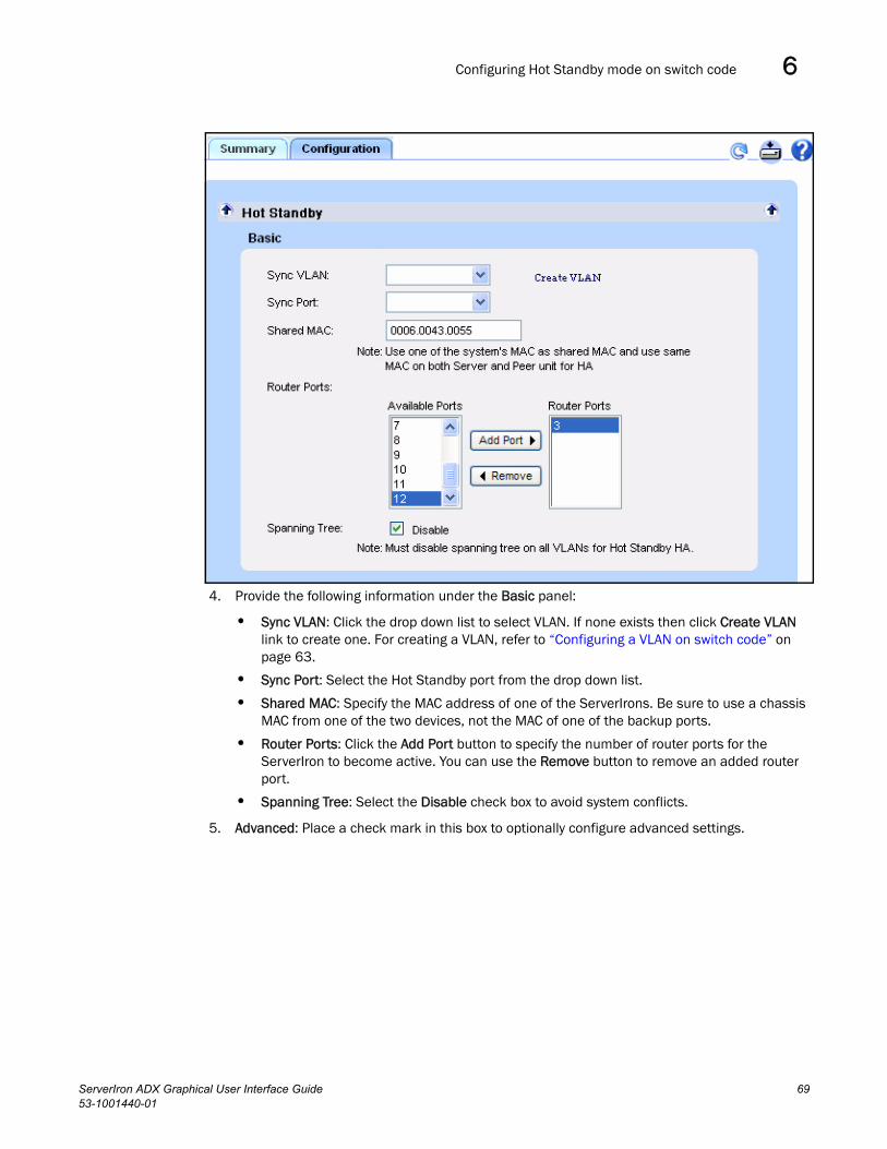
Configuring Hot Standby mode on switch code 6
4. Provide the following information under the Basic panel:
• Sync VLAN: Click the drop down list to select VLAN. If none exists then click Create VLAN link to create one. For creating a VLAN, refer to “Configuring a VLAN on switch code” on page 63.
• Sync Port: Select the Hot Standby port from the drop down list.
• Shared MAC: Specify the MAC address of one of the ServerIrons. Be sure to use a chassis MAC from one of the two devices, not the MAC of one of the backup ports.
• Router Ports: Click the Add Port button to specify the number of router ports for the ServerIron to become active. You can use the Remove button to remove an added router port.
• Spanning Tree: Select the Disable check box to avoid system conflicts.
5. Advanced: Place a check mark in this box to optionally configure advanced settings.
ServerIron ADX Graphical User Interface Guide 6953-1001440-01

Configuring Symmetric Active-Standby Mode6
Provide the following information under the Advanced panel:
• Backup Preference: Enter the number of minutes for the ServerIron to wait before assuming the active role.
• Track Active VIP Count: Click this check box to include active VIP count in failover decision.
• Track Trunk Port Count: Click this check box to include router port count in failover decision.
• Backup Timer: Enter a value between 5-100 in units of 100 milliseconds to set the timer. The default value is 10.
• Backup Group: Enter the backup group value.
6. Click Apply.
The message operation was successful is displayed.
Configuring Symmetric Active-Standby ModeSymmetric Active-Stand by service is a active-standby VIP. Both ServerIrons handle traffic, but the active VIP handles the L4-7 and the standby VIP serves only as a standby. Each ServerIron is the active ServerIron for a specific set of VIPs, while the other ServerIron is the backup for the same set of VIPs.
NOTESymmetric Active-Stand by mode is supported in both Switch code and Router code. Use of router code is highly recommended.
To configure the Symmetric Active-Standby mode on a ServerIron, follow these steps.
1. Click the System button on the left of GUI screen and select High Availability.
2. Click the Configuration tab.
3. Click the Symmetric Active-Active / Symmetric Active-Standby down arrow to display the parameters to be configured.
70 ServerIron ADX Graphical User Interface Guide53-1001440-01

Configuring Symmetric Active-Standby Mode 6
4. Symmetric Active-Stand by configuration is a six step process in which step2 to step 6 are optional.
5. For Step 1: Assign Sym-Priority & Enable Session Synchronization enter the information for the following fields:
• Sym Priority: Enter the priority value for the ServerIron. The range is 0-225
• Dyn Sym Pri Factor (optional): Specify the value for the dynamic priority.
• Session Sync: Click the image button under this column to enable session synchronization for a specific port. If a port profile is not available a new port profile will be created.
6. For Step 2: (Optional) Enable Symmetric Active-Active HA, by default Disable radio button is selected. Select this button if you wish to enable Symmetric Active-Active HA mode.
7. For Step 3: (Optional) Define Synchronization (Symmetric) Port, enter the following information:
• Select Sync VLAN from the drop down list or click Create VLAN link to create one. For creating a VLAN see “Configuring VLANs” on page 63.
• Click Sync Port drop down list to select the port.
8. For Step 5: (Optional) Create VIP group & associate with VRRP / VRRPE, select New from the drop down list to create a VIP group.
ServerIron ADX Graphical User Interface Guide 7153-1001440-01

Configuring Symmetric Active-Standby Mode6
Enter the information in the following fields:
• VIP Group ID: Enter the VIP group id.
• Member VIPs: Click Add button to include available VIP as a member of this group. You can use Remove button to remove an added VIP.
• Select Interface: Select the required interface from the drop down list.
• Associate VRRE-E VRID: Enter the VRRE-E VRID.
9. For Step 6: (Optional) Advanced Settings, enter the following information:
• Symmetric PDU Rate
For Discover Multiplier, specify the multiplier for the SSLB send and wait interval. You can specify a multiplier from 1 – 60. The default is 1.
For Wait Time Multiplier specify how many multiples of the wait interval the ServerIron will wait for an SSLB discovery packet. You can specify a multiplier from 1 – 60. The default is 20.
72 ServerIron ADX Graphical User Interface Guide53-1001440-01

Configuring Symmetric Active-Active mode 6
• Delay Symmetric: Click the Enable check box and enter the minutes you want the recovered ServerIron to wait before becoming active again.
• Group ID: Enter the group id.
10. Click Apply.
The message operation was successful is displayed.
Configuring Symmetric Active-Active modeSymmetric Active-Active mode both the ServerIrons handle traffic (active-active), and both ServerIrons are active for the same VIP on both ServerIrons.
NOTESymmetric Active-Active mode is supported in both Switch code and Router code. Use of router code is highly recommended.
To configure Symmetric Active-Active mode on a ServerIron follow these steps.
1. Click the System button on the left of GUI screen and select High Availability.
2. Click the Configuration tab.
3. Click the Symmetric Active-Active / Symmetric Active-Standby down arrow. The window displays the configuration details in a step by step process.
ServerIron ADX Graphical User Interface Guide 7353-1001440-01

Configuring Symmetric Active-Active mode6
4. For Step 1: Assign Sym-Priority & Enable Session Synchronization enter the information for the following fields:
• Sym Priority: Enter the priority value for the ServerIron. The range is 0-225
• Dyn Sym Pri Factor (optional): Specify the value for the dynamic priority.
• Session Sync: Click the image button under this column to enable session synchronization for a specific port. If a port profile is not available a new port profile will be created.
5. For Step 2: (Optional) Enable Symmetric Active-Active HA, click the Enable radio button.
6. For Step 4: (Optional) Define Active-Active Port, enter the following information:
• Select VLAN from the Sync VLAN drop down list or click Create VLAN link to create one. For creating a VLAN see “Configuring VLANs” on page 63.
• Select the required port from the Active-Active Port drop down list.
7. Optionally configure other parameters.
8. Click Apply.
The message operation was successful is displayed.
74 ServerIron ADX Graphical User Interface Guide53-1001440-01

Displaying High Availability Summary 6
NOTEYou can only enable one of the three HA modes on ServerIron.
Displaying High Availability SummaryYou can display the details of the following from the Summary tab:
• Displaying Hot Standby Summary
• Displaying Symmetric Active-Standby and Symmetric Active-Active Summary
Displaying Hot Standby SummaryTo display hot standby summary, follow these steps.
1. Click the System button on the left of GUI screen and select High Availability.
2. Click the Summary tab.
3. Click Hot Standby down arrow to display the configuration details for the Hot Standby mode configured on a ServerIron.
For switch code if this mode is configured then the details will appear as shown in the image below.
NOTEFor router code this mode is not applicable and hence the message Hot Standby High Availability mode is not enabled will be displayed.
ServerIron ADX Graphical User Interface Guide 7553-1001440-01

Displaying High Availability Summary6
Displaying Symmetric Active-Standby and Symmetric Active-Active SummaryTo display the Symmetric Active-Standby and Symmetric Active-Active summary, follow these steps.
1. Click the System button on the left of GUI screen and select High Availability.
2. Click the Summary tab.
3. Click Symmetric Active-standby / Active-Active down arrow to display the configuration details for the Symmetric Active-Stand by and Symmetric Active-Active mode configured on a ServerIron.
The Summary window is displayed.
76 ServerIron ADX Graphical User Interface Guide53-1001440-01

ServerIron ADX Graphical User Interface Guide53-1001440-01
Chapter
7
Configuring Layer 7 SwitchingIn this chapter•Creating a Layer 7 Switching Rule (Request). . . . . . . . . . . . . . . . . . . . . . . . . 77
•Creating a Layer 7 Request Policy . . . . . . . . . . . . . . . . . . . . . . . . . . . . . . . . . 80
•Enabling Layer 7 Switching (HTTP Requests) . . . . . . . . . . . . . . . . . . . . . . . . 82
•Displaying Layer 7 Summary (HTTP Requests) . . . . . . . . . . . . . . . . . . . . . . . 82
•Creating Layer 7 Rules for HTTP Response . . . . . . . . . . . . . . . . . . . . . . . . . . 83
•Creating Layer 7 Policies for HTTP Responses . . . . . . . . . . . . . . . . . . . . . . . 84
•Enabling Layer 7 Switching for HTTP Responses . . . . . . . . . . . . . . . . . . . . . 87
•Displaying Layer 7 Summary of Response Rules, Policies and Associated virtual service 88
•Using the L7 Switching Request Wizard . . . . . . . . . . . . . . . . . . . . . . . . . . . . 89
Creating a Layer 7 Switching Rule (Request)1. Click the L7 Traffic Management button on the context bar.
The L7 Traffic Management functions are displayed below.
2. Click the L7 Switching (Request) link to display the configuration tabs.
77

Creating a Layer 7 Switching Rule (Request)7
3. Click the Req. Rule tab.
4. Select New from the drop down list.
5. Provide the following information:
• Name: Enter a name for the rule.
• Type: Select the type of rule from the drop down list.
The appropriate parameters are displayed depending on what Type you selected. Fill in the values for the parameters displayed.
• Case Insensitive: Check this box if you want the rule to be case insensitive.
6. Click Apply.
78 ServerIron ADX Graphical User Interface Guide53-1001440-01

Creating a Layer 7 Switching Rule (Request) 7
The rule is listed in the Rule Summary table. You can click the Edit button in the table to modify the rule or select it from the drop down list at the top of the page, next to the New button. You can also delete the rule from the Rule Summary table. However, you cannot edit or delete rules if they are in use.
Click the arrow next to rule name in Rule Summary table to display its details.
Creating a Nested RuleThe following describes how to create a Nested Rule.
1. Click the Nested Rules down arrow to display the parameters for nested rules.
2. Specify the Name for the nested rule.
3. Identify individual rules and select the appropriate operator (AND, OR) from the drop down menu.
ServerIron ADX Graphical User Interface Guide 7953-1001440-01

Creating a Layer 7 Request Policy7
You can use the NOT operator by placing a check mark in the NOT box.
ServerIron starts generating an expression for the Nested Rule, which will be visible in grey color in the Input Expression field.
4. To add brackets to an expression, select the radio button for the Input Expression field and build your own custom expression.
5. Click Apply when you have finished.
The nested rule is created and is listed in the Rule Summary table.
Creating a Layer 7 Request Policy1. With the L7 Switching (Request) selected from the L7 Traffic Management button, click the
Req. Policy tab.
2. Select New from the drop down list.
3. Enter the name of the Layer 7 policy.
4. Click Add.
The fields to define the policy are displayed.
80 ServerIron ADX Graphical User Interface Guide53-1001440-01

Creating a Layer 7 Request Policy 7
5. Select a rule from the Rule drop down list. If a rule is not created already, then you can define one by clicking the Create New Rule link.
6. Select an action from the Action drop down list.
Depending on the selected Action, the display changes and the system asks for additional information.
7. Provide the required additional information and click Add Rule to Policy.
8. Repeat step 4 to step 7 if you wish to add more rules to this policy. You can also add a default rule to the policy.
The Rule is listed in the policy table. You can delete a rule from the policy table by clicking Del. You can also click the down arrows to display details for a rule.
ServerIron ADX Graphical User Interface Guide 8153-1001440-01

Enabling Layer 7 Switching (HTTP Requests)7
Enabling Layer 7 Switching (HTTP Requests)1. With the L7 Switching (Request) selected from the L7 Traffic Management button, click the L7
Switching tab.
2. Select a virtual server from the Virtual Server drop down list or click the Create Virtual Server link to create one.
3. Select a virtual port from the Virtual Port drop down list or click the Add Virtual Port link to create one.
4. Select Enable to enable Layer 7 switching under the selected VIP and VIP port; select Disable to disable Layer 7 switching.
5. Select a request policy from the Request Policy drop down list or click the Create New Policy link to create one.
6. Click Apply.
Displaying Layer 7 Summary (HTTP Requests) To display a summary of L7 request rules, policies and switching definitions, click the Summary tab on the L7 Switching (Request) page.
82 ServerIron ADX Graphical User Interface Guide53-1001440-01

Creating Layer 7 Rules for HTTP Response 7
Click the Request Rules button to display summary of Layer 7 rules for HTTP requests. Click the down arrow next to the rule name to display details for that rule. Rules that are not in use can be modified or deleted.
Click the Request Policies button to display a summary Layer 7 policies for HTTP requests. Click the down arrow next to the policy name to display its details. You can edit or delete polices from the summary.
Click the L7 Switching button to display the summary of VIPs that are enabled with Layer 7 switching for HTTP requests. Click the down arrow next to the policy name to view its details. You can also click Edit to modify the policy or Unbind to remove the policy from the virtual server.
For example, the following shows a summary of the Layer 7 rules for HTTP requests.
Creating Layer 7 Rules for HTTP Response1. Click the L7 Switching (Response) link from the L7 Traffic Management button.
2. Click the Resp. Rule tab.
3. Click New from the drop down list.
4. Provide the following information:
• Name: Name of the response rule.
• Type: Identify the type of the response rule: response status code, response header or response body. Select from the drop down list.
ServerIron ADX Graphical User Interface Guide 8353-1001440-01

Creating Layer 7 Policies for HTTP Responses7
The display changes depending on the selected rule type. Fill in the requested data.
5. Click Apply.
The new rule is listed in the Rule Summary table. You can edit or delete rules.
Creating Layer 7 Policies for HTTP Responses1. With the L7 Switching (Response) selected from the L7 Traffic Management button, click the
Resp. Policy tab.
2. Select New from the drop down list.
3. Enter the name of the Layer 7 policy for HTTP response.
4. Click Add.
84 ServerIron ADX Graphical User Interface Guide53-1001440-01

Creating Layer 7 Policies for HTTP Responses 7
There are two types of L7 HTTP response policies - HTTP header rewrite, HTTP body rewrite:
• For HTTP header rewrite policy, click the down arrow next to Response Rewrite on HTTP Header and configure as described in “Configuring Response Rewrite on HTTP Header” on page 85.
• For HTTP body rewrite policy, click the down arrow next to Response Rewrite on HTTP Body and configure as described in “Configuring Response Rewrite on HTTP Body” on page 86.
Configuring Response Rewrite on HTTP Header1. L7 policy creation for HTTP header rewrite is a two step process. In the first step, select the L7
response rule that identifies the status code in the response packets on which the L7 response policy should act upon. In the second step, select the rule and action for the header rewrite.
2. For Step 1: under the Response Rewrite on HTTP Header, select the HTTP Response Status Code Rule which identifies the response packets on which L7 policy should act upon. If the rule is not present, then click the Create New Rule link to create a new rule.
3. Click Add to add the rule.
ServerIron ADX Graphical User Interface Guide 8553-1001440-01

Creating Layer 7 Policies for HTTP Responses7
4. For Step 2 under the Response Rewrite on HTTP Header, select a rule from the drop down list that identifies an HTTP response header name and the string that needs to be rewritten. If the rule is not present, then click the Create New Rule to create a new one.
5. Enter a New String Value. The Offset and Length parameters are automatically filled in.
6. Click Add Rules to Policy.
The new Layer 7 Response Policy is added to the Policy table. You can click Del to delete a rules from inside the policy.
Configuring Response Rewrite on HTTP Body1. To create HTTP body rewrite policy then click the down arrow next to Response Rewrite on HTTP
Body and follow the steps below:
L7 policy creation for HTTP body rewrite is a two step process. In the first step, select the L7 request rule that identifies the flow whose response needs L7 rewrite. In the second step, select the rule and action for the body rewrite.
2. For Step 1 under the Response Rewrite on HTTP Body, select the HTTP Request Rule whose response packet needs to be acted upon or select HTTP Response Rule to identify if the response packet needs to be acted upon. If rule is not present then click the Create New Rule link to create a new rule.
3. For step 2 under Response Rewrite on HTTP Body, select the HTTP Response Body String Rule. If the rule is not present then click the Create New Rule link to create a new rule.
4. After selecting the rule, its old value is displayed. If necessary, enter the new value for any of the fields displayed.
5. Click Add Rules to Policy.
The new Layer 7 Response Policy is added to the Policy table. You can click Del to delete a rules from inside the policy.
86 ServerIron ADX Graphical User Interface Guide53-1001440-01

Enabling Layer 7 Switching for HTTP Responses 7
Enabling Layer 7 Switching for HTTP ResponsesBefore enabling Layer 7 Switching for HTTP Responses, you need to define the following in the ServerIron:
• Virtual Server
• Virtual Server Port
• Layer 7 Response Policy
If these objects are not defined, then links are provided from the Layer 7 Switching tab to create new ones.
To enable Layer 7 switching for HTTP responses:
1. Select theL7 Switching (Response) from the L7 Traffic Management button.
2. Click the L7 Switching tab.
ServerIron ADX Graphical User Interface Guide 8753-1001440-01

Displaying Layer 7 Summary of Response Rules, Policies and Associated virtual service7
3. Provide the following information:
• Virtual Server: Select the virtual server for which you wish to enable Layer 7 switching from the drop down list. If none exists, then click the Create Virtual Server link to create one.
• Virtual Port: Select one from the drop down list or click Add Virtual Port to create one.
• Response Policy: Select one from the drop down list or click the Create New Policy link to create one.
4. Click Apply.
Displaying Layer 7 Summary of Response Rules, Policiesand Associated virtual service
You can display summaries of Layer 7 rules, response policies and associated virtual servers from the Summary tab. Select L7 Switching (Response) > Summary tab.
Click the Response Rules radio button to display the summary of response rules. Click the down arrow next to the rule name to display details for that rule. Rules that are not in use can be modified or deleted.
Click the Response Policies radio button to display a summary of a response policy. Click the down arrow next to the policy name to display its details. Click the Edit button if you wish to make changes, or Delete button to delete the policy.
Click the L7 Switching radio button to display virtual servers that have Layer 7 response policies associated with them. Click the down arrow next to the policy name to view its details. You can also click Edit to modify the policy or Unbind to remove the policy from the virtual server.
88 ServerIron ADX Graphical User Interface Guide53-1001440-01

Using the L7 Switching Request Wizard 7
For example, the following shows a summary for Response Rules.
You can click the down arrow to the right of Name to display details for a rule.
NOTEA rule in use cannot be edited or deleted.
Using the L7 Switching Request WizardThe L7 Switching Wizard page provides simple, step-by-step instructions for creating a sample L7 switching configuration. You can choose from one of the pre-designed sample scenarios and the GUI will navigate you through rule creation, policy creation and policy association pages.
Launch the WizardTo launch the Wizard, do the following.
1. Click the L7 Switching (Request) link to display the configuration tabs.
2. Click the Wizard tab.
3. When the start page for the Wizard displays, select a scenario from the drop down list and click Start.
ServerIron ADX Graphical User Interface Guide 8953-1001440-01

Using the L7 Switching Request Wizard7
4. The Wizard guides you through the steps for creating a Layer 7 switching configuration.
Wizard 1: Traffic Forwarding based on URL PrefixThe following steps describe how to configure Traffic Forwarding Based on a URL Prefix by following these steps:
Step 1: Creating a Rule – In this step, the rule is named and the Type, Operator, and Value are defined.
Step 2: Creating a Policy – In this step, the policy is named and defined.
Step 3: Enabling L7 Switching – In this step, the Virtual Server and Virtual Port are enabled for L7 Switching and the L7 Policy is applied.
Step 1: Creating a RuleSelecting the Traffic forwarding based on URL Prefix scenario, displays the Create Rule page as shown in the following:
90 ServerIron ADX Graphical User Interface Guide53-1001440-01

Using the L7 Switching Request Wizard 7
1. Enter a name for the rule. The type and the operator with this rule would be URL and Prefix respectively. Click Case Insensitive if case sensitivity is not required.
2. Click the Create button to create the rule. This rule will then be displayed under Rule summary table.
3. Repeat step 1 & step 2 within this procedure if you wish to create additional rules.
4. Click the >> button to continue to the next step.
Step 2: Creating a policyThe second step is to create a policy for the rule.
1. On the Create Policy page, enter a name for the policy, select the rule to which the policy will be applied, select an action, and provide any information required for the policy.
2. Click Add Rule to Policy. The new policy is listed in the Policy Summary table.
ServerIron ADX Graphical User Interface Guide 9153-1001440-01

Using the L7 Switching Request Wizard7
3. Repeat step 1 & step 2 within this procedure if you wish to create additional rules.
4. Click the >> button to continue to the next step.
Enabling L7 SwitchingThe last step is to enable the rule.
When the Enable Switching page appears, the virtual server to which the rule will be enabled, the virtual server port, and the selected request policy are displayed.
1. Select the Virtual Server and Virtual Port for which you wish to enable L7 switching.
2. Click the Enable radio button to enable the rule.
3. Select the L7 policy from Request Policy drop-down list.
4. Click Apply. The L7 switching details are now displayed in Summary table.
92 ServerIron ADX Graphical User Interface Guide53-1001440-01

Using the L7 Switching Request Wizard 7
5. Click Finish to complete the procedure.
Wizard 2: Traffic Forwarding based on URL SuffixTraffic Forwarding Based on URL Suffix is configured using the same procedure as "Wizard 1:" as described in “Wizard 1: Traffic Forwarding based on URL Prefix” on page 90.
ServerIron ADX Graphical User Interface Guide 9353-1001440-01

Using the L7 Switching Request Wizard7
94 ServerIron ADX Graphical User Interface Guide53-1001440-01

ServerIron ADX Graphical User Interface Guide53-1001440-01
Chapter
8
Displaying StatisticsIn this chapter•Statistics Overview . . . . . . . . . . . . . . . . . . . . . . . . . . . . . . . . . . . . . . . . . . . . . 95
•Viewing System Resources . . . . . . . . . . . . . . . . . . . . . . . . . . . . . . . . . . . . . . . 96
•Displaying Traffic Statistics for a real server . . . . . . . . . . . . . . . . . . . . . . . . . 97
•Displaying Statistics for a real server port . . . . . . . . . . . . . . . . . . . . . . . . . . 102
•Displaying Statistics for a virtual server. . . . . . . . . . . . . . . . . . . . . . . . . . . . 104
•Displaying Statistics for virtual server port . . . . . . . . . . . . . . . . . . . . . . . . . 106
•Displaying Global Traffic Statistics . . . . . . . . . . . . . . . . . . . . . . . . . . . . . . . . 110
•Displaying Interface Statistics . . . . . . . . . . . . . . . . . . . . . . . . . . . . . . . . . . . 110
•Viewing Syslog entries. . . . . . . . . . . . . . . . . . . . . . . . . . . . . . . . . . . . . . . . . . 114
Statistics OverviewThe ServerIron GUI displays information about system CPU and memory resources; traffic statistics for real servers, virtual server and ports; details on system interfaces, ARP and MAC tables; and system resources.
1. Click the Overview button on the context bar.
2. Click the Statistics link to view system statistics.
By default, real server statistics is displayed.
95

Viewing System Resources8
Viewing System ResourcesInformation about the available system resources can be viewed from the Dashboard link on the Overview button or from the System Resources tab of the Statistics page.
To view system resources from the Statistics page, click Overview > Statistics > and the System Resources tab.
96 ServerIron ADX Graphical User Interface Guide53-1001440-01

Displaying Traffic Statistics for a real server 8
The System Resources page displays CPU and memory utilization of the management processor (MP), and CPU and session utilization of barrel processors (BP).
Displaying Traffic Statistics for a real serverTo display traffic statistics for a real server, follow these steps.
1. Click the Traffic Statistics tab.
2. By default, Traffic Statistics for the first real server is displayed.
3. From the drop down list under the Real Server and Real Port links, select a real server. Select the desired real server using one of the following methods:
• Click the drop down list and select a real server.
• Click the left or right arrow to the sides of the real server drop down list.
ServerIron ADX Graphical User Interface Guide 9753-1001440-01

Displaying Traffic Statistics for a real server8
4. You can select how often the display is refreshed by selecting a value from the Refresh Interval drop down box of the Live Chart bar. The default refresh interval is 10 seconds and it can be adjusted from 5 seconds to 2 minutes.
5. By default, auto-refresh is enabled. You can stop Auto-refresh by clicking the Stop button. Resume the refresh by clicking the Start button again, or start over by clicking the Reset button.
The top portion of the display shows a summary for the real server. The remainder of the page contains several charts that shows the statistical information for the real server:
• “Current Connection Rate” on page 98
• “Current Connections” on page 99
• “Connection Distribution among Application Ports” on page 100
• “Total Accumulated Connections to Server” on page 100
• “Total Accumulated Connections per Application Port” on page 101
• “Received and Transmitted Packets among Application Ports” on page 101
The charts show live client connections to the real servers and the number of packets that have been sent or received by the real server.
Current Connection RateThe Current Connection Rate live chart shows the rate at which the current connections are made to a selected real server.
The X-axis displays the time interval, based on your selection for Refresh Interval. For example, if you select 1-minute interval, one-minute increments are displayed on the X-axis.
The Y-axis shows the connection rate.
98 ServerIron ADX Graphical User Interface Guide53-1001440-01

Displaying Traffic Statistics for a real server 8
Current Connections The Current Connections live chart shows the current connections to a selected real server.
The X-axis displays the time interval, based on your selection for Refresh Interval. For example, if you selected 1-minute intervals, one-minute increments are displayed on the X-axis.
The Y-axis shows the number of connections.
ServerIron ADX Graphical User Interface Guide 9953-1001440-01

Displaying Traffic Statistics for a real server8
Connection Distribution among Application PortsThe Connection Distribution Among Application Ports chart shows the number of current connections for each application port and also displays the peak number of connections for each of these application ports..
Total Accumulated Connections to ServerThe Total Accumulated Connections to Server chart shows the total number of connections that are serviced by a given real server over a period of time.
100 ServerIron ADX Graphical User Interface Guide53-1001440-01

Displaying Traffic Statistics for a real server 8
Total Accumulated Connections per Application PortThe Total Accumulated Connections Per Ports chart shows the total number of connections serviced by a given real server over a period of time for a given application port since the last time the statistics were cleared using the CLI.
Received and Transmitted Packets among ApplicationPortsThe RX & TX Packets Among Application Ports chart shows the number of packets received and transmitted by a real server for a given application port since the last time statistics were cleared using the CLI.
ServerIron ADX Graphical User Interface Guide 10153-1001440-01

Displaying Statistics for a real server port8
Displaying Statistics for a real server port1. Click the Traffic Statistics tab.
2. Click the Real Port link under the tabs.
3. From the drop down list under the Real Server, select the real server name.
4. From the drop down list under the Real Port, select a real server port.
The table at the top of the page displays information about the selected real server port.
5. To view statistics on the Live Chart, select the refresh rate from the Refresh Interval drop down list.
6. Click Start to start or resume the data display, Stop to stop it, or Reset to start over again.
The following charts are displayed:
• “Current Connections on Ports” on page 102
• “Total Accumulated Connections on Ports” on page 103
• “Received and Transmitted Packets on Ports” on page 103
Current Connections on PortsThe Current Connections on Port <port> chart shows the current connection count of a given port on a given real server.
102 ServerIron ADX Graphical User Interface Guide53-1001440-01

Displaying Statistics for a real server port 8
Total Accumulated Connections on PortsThe Total Accumulated Connections on Port <port> chart shows the total number of connections serviced over a period of time by given a real server on a given application port.
Received and Transmitted Packets on PortsThe Rx and Tx Packets on Port <port> chart shows the total number of received and transmitted packets for a given port on a given real server.
ServerIron ADX Graphical User Interface Guide 10353-1001440-01

Displaying Statistics for a virtual server8
Displaying Statistics for a virtual server1. Click the Traffic Statistics tab.
2. Click the Virtual Server link under the tabs.
3. Select the virtual server by using one of the following methods:
• Click the drop down list and select a virtual server.
• Click the left or right arrow to the sides of the virtual server drop down list.
The top portion of the display shows a summary of the statistics for the virtual server.
4. You can select how often the display is refreshed by selecting a value from the Refresh Interval drop down box of the Live Chart bar.
5. Click Start to begin or resume the statistics display. Click Stop to stop it or Reset to start over.
104 ServerIron ADX Graphical User Interface Guide53-1001440-01

Displaying Statistics for a virtual server 8
The page displays the following charts:
• “Connection Distribution among Application Ports” on page 105
• “Total Accumulated Connections to Server” on page 105
• “Total Accumulated Connections per Port” on page 106
Connection Distribution among Application PortsThe Connection Distribution Among Application Ports chart shows the number of current connections to the virtual server for each application port at a given point of time.
Total Accumulated Connections to Server The Total Accumulated Connections to Server chart shows the total number of connections that are serviced by the virtual server over a given period of time since the last reboot.
ServerIron ADX Graphical User Interface Guide 10553-1001440-01

Displaying Statistics for virtual server port8
Total Accumulated Connections per PortThe Total Accumulated Connections per Port shows the total number of connections serviced by a given virtual server on a given application port over a period of time.
Displaying Statistics for virtual server port1. Click the Traffic Statistics tab.
2. Click the Virtual Port link under the tabs.
3. From the Virtual Server drop down list, select a virtual server. Use one of the following methods:
106 ServerIron ADX Graphical User Interface Guide53-1001440-01

Displaying Statistics for virtual server port 8
• Click the drop down list and select a virtual server.
• Click the left or right arrow to the sides of the virtual server drop down list.
4. From the Virtual Port drop down list, select a virtual port. Use one of the following methods:
• Click the drop down list and select a virtual port.
• Click the left or right arrow to the sides of the virtual port drop down list.
The top portion of the display shows the summary of statistics for the virtual server port.
5. You can select how often the display is refreshed by selecting a value from the Refresh Interval drop down box of the Live Chart bar.
6. Click Start to start or resume the statistics display. Click Stop to stop it or Reset to start over.
The page shows the following charts:
• “Current Connections on Ports” on page 107
• “Current Connection Distribution among Real Servers” on page 108
• “Total Accumulated Connections” on page 108
• “Total Accumulated Connection Distribution among Real Servers” on page 109
Current Connections on PortsThe Current Connections on Port <port> shows the number of current connections being serviced on a given virtual server at a given point of time.
ServerIron ADX Graphical User Interface Guide 10753-1001440-01

Displaying Statistics for virtual server port8
Current Connection Distribution among Real ServersThe Current Connection Distribution Among Real Servers shows the distribution of connections among backend real servers that are bound to a given virtual server on a given virtual port.
Total Accumulated ConnectionsThe Total Accumulated Connections on Port <port> shows the total number of connections serviced on a given virtual port by a given virtual server over a period of time since the last system reboot.
108 ServerIron ADX Graphical User Interface Guide53-1001440-01

Displaying Statistics for virtual server port 8
Total Accumulated Connection Distribution among Real Servers The Total Accumulated Connection Distribution Among Real Servers shows the distribution among real servers for the total number of connections that are serviced on a given virtual port by a given virtual server over a period of time since last system reboot. Each column or bar indicates the total number of connections serviced by the associated real server on it corresponding real port.
ServerIron ADX Graphical User Interface Guide 10953-1001440-01

Displaying Global Traffic Statistics8
Displaying Global Traffic Statistics1. Click the Traffic Statistics tab.
2. Click the Traffic link under the tabs.
Global traffic statistics for the device is displayed.
Displaying Interface StatisticsTo display statistics for an interface:
1. Click the Overview button on the context bar.
2. Click the Statistics link to display the tabs for the feature.
3. Click the Interface / IP tab.
4. Click the I/F Summary link to display a quick summary of all the interfaces on the ServerIron.
110 ServerIron ADX Graphical User Interface Guide53-1001440-01

Displaying Interface Statistics 8
5. Click the I/F Details link to view more details for an interface.
The Interface Details page provides data for the interface attributes, its utilization and errors on the interface.
6. Click the IP link to display ICMP, IP, TCP, and UDP protocol statistics.
ServerIron ADX Graphical User Interface Guide 11153-1001440-01

Displaying Interface Statistics8
7. Click the ARP link to view information about the entries in the ARP Cache.
The ARP table shows IP to MAC address association.
8. Click the MAC link to display Layer 2 MAC table information. The MAC table shows the association between a MAC address and a system port.
112 ServerIron ADX Graphical User Interface Guide53-1001440-01

Displaying Interface Statistics 8
ServerIron ADX Graphical User Interface Guide 11353-1001440-01

Viewing Syslog entries8
Viewing Syslog entriesClick the System Log tab to view the entries in the Syslog. The System Log page shows the date and time when the entry was generated, the severity of the entry, and the generated message.
114 ServerIron ADX Graphical User Interface Guide53-1001440-01