service bulletin sb685 - thermo king · evolution software version 1.7 was released. they were to...
TRANSCRIPT
Service Bulletin
SB685
Date: 8/18/2017
Subject: TriPac EVOLUTION Communications Update
Bulletin Location: TSA Info Central\Service Bulletins
Units: All TriPac EVOLUTION
Summary: This bulletin updates and replaces TT760. Computers with Microsoft Windows 10, Version 1607 and later, are not able to communicate with TriPac EVOLUTION through TK Monitor or previous service tool software. A new EVOLUTION Service Tool R2 has been released to allow all Windows computers to communicate with the TriPac EVOLUTION Base Controller. The EVOLUTION Service Tool R2 will be installed on the service computer. It retains all the features found in TK Monitor. The EVOLUTION Service Tool R2 software is available on Thermo King Info Central and will be on the www.thermoking.com Website. Uninstall and delete the previous version of EVOLUTION Service Tool.
Discussion: Thermo King TriPac EVOLUTION units have TK Monitor communication software built into the Base Controller of each unit. It allowed PC type computers to establish two way communications with the EVOLUTION control system without special software being loaded on the computer. Microsoft Windows 10, 8 and updated 7 computers would not communicate with TK Monitor. In 2015 Thermo King developed the first EVOLUTION Service Tool. In 2016 TriPac EVOLUTION software Version 1.7 was released. They were to re-establish communication with Microsoft Windows 10 through Version 1511. When Windows 10 Version 1607 was released communication issues with TK Monitor returned.
The EVOLUTION Service Tool R2 software application has been developed to allow all Windows based computers to communicate with the TriPac EVOLUTION Base Controller. This application software is installed on the service computer. It will communicate directly with the EVOLUTION Base Controller. We are moving toward using a service tool on the service computer as standard. This will allow communication that is not threatened by software changes made by Microsoft.
The EVOLUTION Service Tool R2 is a full function communication tool. It will allow all the features found in TK Monitor. These include setup and run-in of units after installation. It will also allow viewing and clearing of alarms, viewing real time diagnostic information, performing software updates and operation of all Service Test modes. It will also perform datalogger downloads and system restarts.
Availability: The EVOLUTION Service Tool R2 software can be downloaded from TSA Info Central/Software and Downloads/APU/EVOLUTION Service Tool R2. We plan to make it available
2
on the www.thermoking.com Website. The downloaded zip file must be extracted and saved on the service computer. Uninstall and delete the previous version of EVOLUTION Service Tool.
Communication Using EVOLUTION Service Tool R2
Where Used
All TriPac EVOLUTION units if the Microsoft Windows service computer is having difficulty communicating with the TriPac EVOLUTION Base Controller.
Purpose
External communication with the Base Controller on the TriPac EVOLUTION Interface Board through TK Monitor is not possible when using a Microsoft Windows 10 Version1607 computer. The EVOLUTION Service Tool R2 will be installed on the service computer to allow access to the Base Controller using a proprietary interface. The EVOLUTION Service Tool R2 will use the USB plug (J39) on the Interface Board and a USB cable with a Mini B connector (P/N 204-2000). Communication will require the use of an IBM compatible PC service computer. The EVOLUTION Service Tool R2 is not dependent on Microsoft Internet Explorer and will work with all versions of Microsoft Windows.
The EVOLUTION Service Tool R2 will retrieve real time information from the TriPac EVOLUTION Base Controller and display it on the service computer. The EVOLUTION Service Tool R2 will provide a system interface to flash load system upgrades, program system features, view real time system information, initiate Service Test Modes and allow alarm clearing capabilities. It will also allow a data logger down load and Cold Restart.
Materials Required
PC type computer. EVOLUTION Service Tool R2 software installed on service computer. USB to Mini B interconnect cable. (204-2000)
Unable to Communicate Using EVOLUTION Service Tool R2
If the service computer is not able to communicate with the TriPac EVOLUTION Base Controller using the EVOLUTION Service Tool R2 perform the following:
1. Verify TriPac EVOLUTION system is turned on at the HMI.
2. Remove the cover from the system control box.
3. Check the status of the green ON LED on the interface board.
a. Blinking once per second = Normal. Controller is communicating. Check service computer for proper connections.
3
b. Off = Controller is not reacting to the ON signal from the HMI. Refer to Diagnostic Manual Section 5, HMI Control Panel Diagnosis.
c. Blinking more than once per second = Controller is stuck in boot mode and not communicating. Refer to Diagnostic Manual, Section 6, A57A, Power Cycle Base Controller.
Menus
The following menu choices are on tabs at the top of the screen. They allow direct access to desired system features:
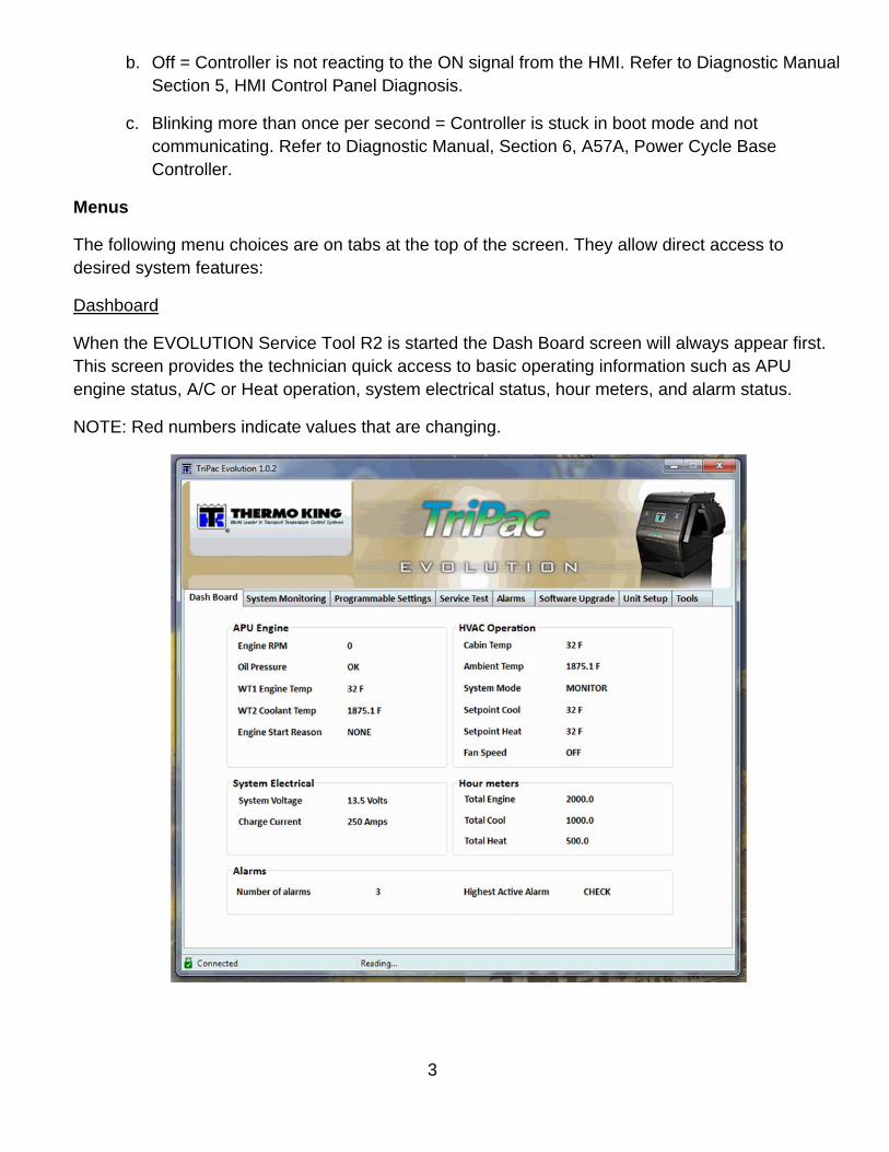
Dashboard
When the EVOLUTION Service Tool R2 is started the Dash Board screen will always appear first. This screen provides the technician quick access to basic operating information such as APU engine status, A/C or Heat operation, system electrical status, hour meters, and alarm status.
NOTE: Red numbers indicate values that are changing.
4
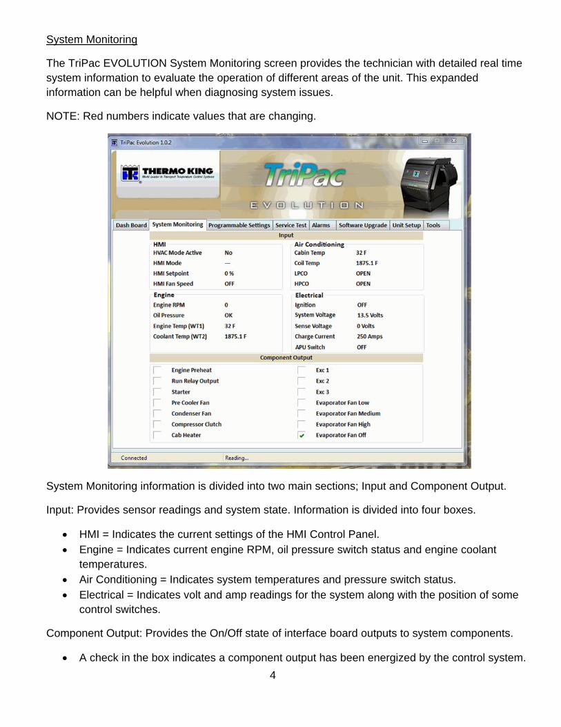
System Monitoring
The TriPac EVOLUTION System Monitoring screen provides the technician with detailed real time system information to evaluate the operation of different areas of the unit. This expanded information can be helpful when diagnosing system issues.
NOTE: Red numbers indicate values that are changing.
System Monitoring information is divided into two main sections; Input and Component Output.
Input: Provides sensor readings and system state. Information is divided into four boxes.
HMI = Indicates the current settings of the HMI Control Panel. Engine = Indicates current engine RPM, oil pressure switch status and engine coolant
temperatures. Air Conditioning = Indicates system temperatures and pressure switch status. Electrical = Indicates volt and amp readings for the system along with the position of some
control switches.
Component Output: Provides the On/Off state of interface board outputs to system components.
A check in the box indicates a component output has been energized by the control system.

5
Programmable Settings
This screen provides a central location to view or change the value for all of the programmable features. Refer to Diagnostic Manual Section 3, Software Description for information about the available programmable features. Select a feature. Click on the arrows to scroll up or down to the desired setting. New settings for multiple features may be selected. If Set System Clock is checked the controller real time clock will be set to match system time of the connected computer. All changes will be saved when the Update Setup button is clicked.
NOTE: System will not accept changes if Password Protection is set to YES. Enter password and retry. The Password boxes near the bottom of the screen will be greyed out and inactive unless the Password Protection feature is programmed Yes.
6
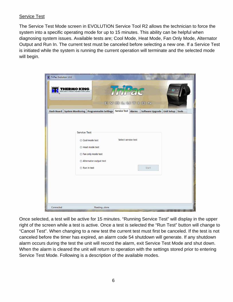
Service Test
The Service Test Mode screen in EVOLUTION Service Tool R2 allows the technician to force the system into a specific operating mode for up to 15 minutes. This ability can be helpful when diagnosing system issues. Available tests are; Cool Mode, Heat Mode, Fan Only Mode, Alternator Output and Run In. The current test must be canceled before selecting a new one. If a Service Test is initiated while the system is running the current operation will terminate and the selected mode will begin.
Once selected, a test will be active for 15 minutes. “Running Service Test” will display in the upper right of the screen while a test is active. Once a test is selected the “Run Test” button will change to “Cancel Test”. When changing to a new test the current test must first be canceled. If the test is not canceled before the timer has expired, an alarm code 54 shutdown will generate. If any shutdown alarm occurs during the test the unit will record the alarm, exit Service Test Mode and shut down. When the alarm is cleared the unit will return to operation with the settings stored prior to entering Service Test Mode. Following is a description of the available modes.
7
While operating in a Service Test Mode the Dashboard, System Monitoring and Alarm screens are available. This will allow the technician to gather real time diagnostic information. Shutdown alarms are still actively protecting the system.
NOTE: Operator should wait for system response before selecting new setting or changing to a new screen.
Cool Mode Test:
Use to check operation of air conditioning system where cool ambient conditions prevent normal activation. The APU engine will start or continue to run. The compressor, evaporator fan and condenser fan are turned on. The evaporator fan will run at the driver selected speed (default minimum low speed). Fan speed may be changed at the HMI while in the test. Setpoint and cab temperature are not monitored. The compressor may start and stop during the test based on the Low Pressure Cutout (LPCO) or evaporator coil temperature below 32 F. The functions of heat mode are disabled. When the optional 120 amp alternator is installed and 120 Amps option selected during Unit Setup, load management is required as in regular cool mode. See Diagnostic Manual Cool Section 4, Engine Load Management.
Heat Mode Test:
Use to check operation of the cab heater where warm ambient conditions prevent normal activation. The interface board heat output circuit (YEL, J13-2) is turned on. The HMI setpoint setting is set to maximum (90 F [32 C]). If cab temperature is higher than maximum setpoint the heater will not start. The other functions of Fan and Cool modes are disabled. The APU engine will not run. When Heat Mode Test is terminated the heater will enter a cool down mode.
Fan Only Mode Test:
Use to check operation of system fans. Evaporator, condenser and pre-cooler fans are on. Evaporator fan speed can be changed at the HMI. The other functions of Heat and Cool modes are disabled. The APU engine will not run. This is the only way to force the pre-cooler fan to run.

8
Alternator Output Test:
Use to check 120 amp alternator output while ambient and cab temperatures are high. The APU engine will start or continue to run. Air conditioning compressor operation is disabled. Engine Load Management system is temporarily disabled. The FLD1 circuit will be grounded. Without Load Management active the optional 120 amp alternator is allowed to charge at the full output requested by the voltage regulator, even in high ambient conditions. Has no effect on the 65 amp charging system.
NOTE: The test does not force the alternator to maximum output. It is not “Full Field”.
Run In Test:
Use after new unit installation to perform the required 10 hour run in. This test allows the air conditioning system to continue operating to load the engine when ambient and/or cab temperature is low. This is done by allowing the heater to run while air conditioning. The test does not guarantee the APU engine will run for 10 hours. It creates conditions to help the engine run with a load when ambient temperature is below normal air conditioning range.
The test mode will initiate a 10 hour timer. The engine will start or continue to run. The air conditioning system will be activated. Cool setpoint will be set to 60 F. Evaporator Coil and Cab Temperature sensors along with pressure switches are functional. Compressor may cycle based on setpoint, cab temperature, coil temperature and system pressure. Heat system will also be activated. Heat setpoint will be set to 80 F. It is intended the heater will help keep cab temperature high enough for the air conditioning system to operate.
When ambient temperature is below 60 F the heater begins to have difficulty keeping the cab temperature above setpoint. The compressor may cycle on/off based on setpoint or the Coil Temperature sensor. If system suction pressure is low the LPCO may open, temporarily stopping the air conditioning function. If this occurs three times in an hour an alarm code 93 may generate. Air conditioner operation will stop. The Run In test does not force the engine to run. As ambient temperature falls so will engine run time during the 10 hour Run In Test. If cab temperature remains below setpoint for more than eight minutes the engine may cycle off. Cab temperature must rise more than three degrees above setpoint before the engine will restart. Engine Load Management will be active if the 120 Amps option was selected during Unit Setup.
EVOLUTION Service Tool R2 may be turned off and computer disconnected while Run In Test is running. At the end of the 10 hour run in period the system will shut down with an alarm in the [ENG] group. It will be a code 54, Test Mode Timeout. Turning system off at the HMI will clear the alarm. Best practice would be to reconnect EVOLUTION Service Tool R2. Verify there are no additional alarms and that the hour meter reads some engine run time. The code 54 should be cleared.
NOTE: Changing system mode at HMI or entering Standby mode will cancel the Run In test. Do not start and move truck once Run In test has been started.

9
Alarms
The Alarms screen allows the technician to view alarm history and clear alarms. Alarms that are cleared by turning the HMI OFF/ON will remain on the list as inactive and can be cleared along with the active alarms through the Alarm screen. The screen will indicate the level of each alarm. It will also allow alarms to be cleared. Cleared alarms remain in data logger memory. Alarm history may be viewed in a download.
NOTE: Active alarms cleared from the alarm list by the EVOLUTION Service Tool R2 will not be reset until the system is turned Off at the HMI.
Refer to Diagnostic Manual Section 5, Diagnostics, Alarm Codes for additional information.

10
Software Upgrade
The currently installed software revisions for Controller, HMI and TK Monitor will be listed. Software upgrades can be flash loaded for the Controller or HMI. Software for TK Monitor can also be upgraded through this screen. For detailed information about specific system software features refer to Diagnostic Manual Section 3, Software Description. Also review the Service Bulletin published at the time of software release.
NOTE: System will not accept changes if Password Protection is set to YES. Enter password and retry.

11
Unit Setup
This screen provides access to unit configuration and identification settings. These settings will typically be made when the unit is installed. Failure to setup the unit to match the hardware configuration will cause operating issues. Failure to program unit information will make datalogger files difficult to identify. Refer to Diagnostic Manual Section 3, Software Description for information about all available configuration settings.
NOTE: System will not accept changes if Password Protection is set to YES. Enter password and retry.

12
Tools
This is a technician access Tools screen. It provides access to advanced system service functions. Click on the Tools tab. A box will appear that says “Tools Password”. Type 4444 in the Password box, click OK.
NOTE: During normal system monitoring and diagnosis it is not necessary to enter this screen.
Download Datalogger
Selecting the Download datalogger button will allow downloading the information recorded in the controller memory to the attached PC computer. TriPac EVOLUTION data logger files are BIN format and cannot be directly viewed. A file converter is required. See Diagnostic Manual, Service Procedure A50A, TriPac EVOLUTION Data Logger in the TriPac EVOLUTION Diagnostic Manual.
Restarts
Warm Restart: Performing a Warm Restart will reboot the Base Controller on the Interface Board. This is a “soft” restart that is equivalent to power cycling the Interface board (turning system off at the HMI or removing power from #2 terminal). Hour meters, data logger and programmable settings are retained. A Warm Restart may be required after installing a software update.

13
Cold Restart: Performing a Cold Restart will reboot the Base Controller on the Interface Board and reset the Programmable Settings to their default value. Data logger information will be lost. Any active alarms will be cleared and alarm history will be lost. Hour meters are retained. Unit Setup settings are retained. Before performing a Cold Restart the programmable feature settings should be recorded and data logger downloaded if possible.
NOTE: A Cold Restart is not a standard service procedure. It should not be performed unless directed by Minneapolis Service Department or as part of a published service procedure.

14
Operation Instructions
Connect to EVOLUTION Service Tool R2 Page 15
Disconnect from EVOLUTION Service Tool R2 Page 16
View and Clear Alarms Page 17
Record or Setup Programmable Features Page 18
Unit Setup Page 19
Set Real Time Clock Page 20
Check Software Revision Page 21
Upgrade System Software Page 21
Operate Service Test Mode Page 23
Controller Cold Restart Page 25
Download Data Logger Page 26
Reset Hour Meters Page 28
Set a Password Page 29
Change a Password Page 30
Bypass the Password Page 31

15
Connect To EVOLUTION Service Tool R2
Step Action Result Comments
1 Remove cover from the
Control Box
2 Connect the EVOLUTION
Service Tool R2 Adapter
Harness (P/N 204-2000) to
the J39 plug on the
Interface board.
May use USB cable with
Mini B connector.
Do not connect to PC
computer at this time.
3 Turn system on at HMI. Wait for selected mode icon to stop
flashing.
4 Verify the green LED
indicator on the Interface
board is flashing.
Should be flashing about once per
second.
On power up LED will flash
rapidly for a few seconds
then rate should return to
normal.
5 Start the PC computer. Wait for the computer to
complete the startup
process.
8 Use “My Computer” or
“Windows Explorer” to
locate the EVOLUTION
Service Tool R2.exe file
downloaded from Thermo
King Info Central. Double
click to start program.
EVOLUTION Service Tool R2 should
open with the Dashboard screen.
There will be no data in any
of the fields.
A “Controller Not
Connected” box will display.
6 Connect the EVOLUTION
Service Tool R2 Adapter
Harness to a USB port on
the service computer.
Click OK in the “Controller Not
Connected” box. Current data will fill in
the fields.
Red numbers indicate
values that are changing
16
Step Action Result Comments
7 Disregard any new data
drive. It is not used with
EVOLUTION Service Tool
R2.
If a new drive window opens you should
close it.
Do not click on any file in
this new drive.
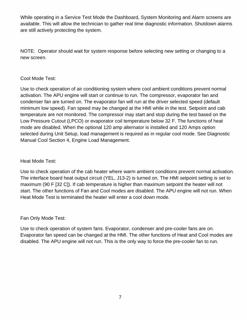
Disconnect From EVOLUTION Service Tool R2
Step Action Result Comments
If operating in Service Test
Mode select Cancel Test in
the Service Test screen.
Returns TriPac EVOLUTION system to
normal operation.
1 Disconnect the Adapter
Harness from the computer
USB port.
A “Lost Communication” box will
appear. Unit will continue to operate.
Service Test Run In will continue if
selected.
Unit data will not be
displayed.
2 Exit EVOLUTION Service
Tool R2 by closing the
program window.
Click X in upper right corner of window. It does not matter if the
Service Tool is closed or
adapter harness is
disconnected first.
3 Disconnect the Adapter
Harness from the Interface
board.
Optional: The Adapter Harness may
remain connected to the interface
board. It should be routed and secured
to an easily accessible location.
4 Shutdown the PC
computer.
5 Replace the Control Box
cover.
6 Verify proper unit operation.
17
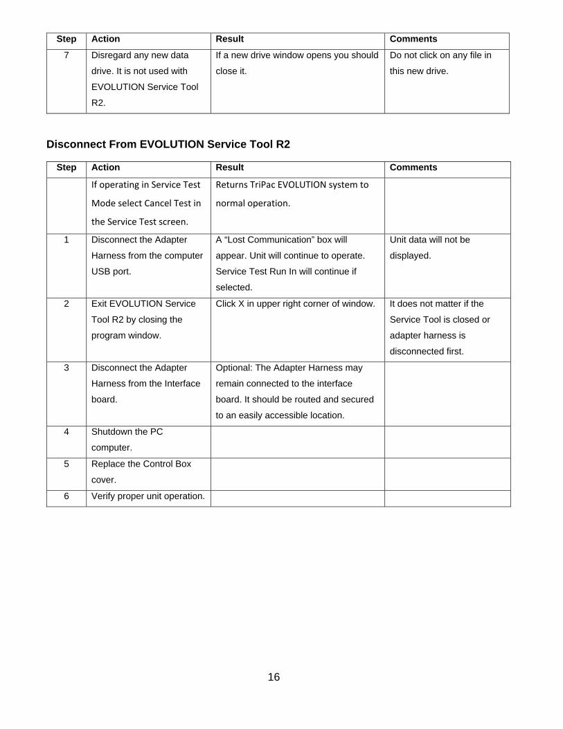
View and Clear Alarms
Step Action Result Comments
1 Connect to EVOLUTION
Service Tool R2.
2 In the tabs on the top of the
EVOLUTION Service Tool
R2 screen select Alarms.
Alarms screen should open. It will
display the Alarm Code, Type and Title
of the listed alarms.
If there are no alarms the
screen will show “No Active
Alarms”. The grid will not
display.
3 Record the listed alarms. Red = Active, Shutdown
Yellow = Active, Check or Log
Gray = Inactive, cleared at HMI
Refer to Diagnostic Manual
Section 5, Alarm Code
Diagnosis.
4 Clear individual alarms by
selecting an alarm. Click
the Clear Selected button.
The alarm will be removed from the list. Alarm may return if alarm
condition still exists.
5 Clear entire alarm list by
selecting the Clear All
button.
NOTE: Active Check or Shutdown
alarms cleared from the list will remain
active until the system is tuned off at the
HMI.
Some alarms may return if
alarm conditions still exists.
6 Alarms have been cleared. Select a new function from the tabs on
the top or refer to Disconnect From
EVOLUTION Service Tool R2.
All alarms are recorded by
the data logger as they
occur.

18
Record or Setup Programmable Features
Step Action Result Comments
1 Connect to EVOLUTION
Service Tool R2.
2 In the tabs on the top of the
EVOLUTION Service Tool
R2 screen select
Programmable Settings.
Programmable Settings screen should
open.
Programmable Feature
setup should be done as
part of new unit installation.
It will setup the software
settings to match customer
requirements and set Real
Time Clock.
3 Note the programmable
feature settings.
If correct: select a new function from the
tabs on the top or refer to Disconnect
From EVOLUTION Service Tool R2.
If incorrect: proceed to next step.
Refer to Diagnostic Manual
Section 3, Software
Description, Programmable
Features.
4 To change setting:
Select the desired setting.
Press up/down arrow to scroll through
options.
Do not select Update Setup
until all desired changes
have been selected.
5 Note Real Time Clock. If correct: proceed to next step.
If incorrect: Select the check box next to
Set System Clock.
The Real Time Clock will be
reset to match the
connected computer. There
is no ability to set a different
time.
6 Select Update Settings The controller will restart. A “Lost Communication”
message will display.
7 Disconnect the Adapter
Harness from the computer.
Refer to Disconnect From
EVOLUTION Service Tool
R2.

19
Unit Setup
Step Action Result Comments
1 Connect to EVOLUTION
Service Tool R2.
2 In the tabs on the top of the
EVOLUTION Service Tool
R2 screen select Unit
Setup.
Unit Setup screen should open. Unit setup should be done
as part of new unit
installation. It will setup the
software to match the
system hardware.
3 Note the programmable
feature settings.
If correct: select a new function from the
tabs on the top or refer to Disconnect
From EVOLUTION Service Tool R2.
If incorrect: proceed to next step.
Refer to Diagnostic Manual
Section 3, Software
Description, Unit Setup.
4 Change setting for
Alternator Capacity and
Engine cooling Option.
Select the desired setting. Press
up/down arrow to scroll through options.
Do not select Update
Settings until all desired
changes have been
selected.
5 Enter unit identification
information.
Click on Unit Serial Number box, type in
serial number.
Click on Unit ID box, type in truck
number.
Serial number from unit
serial plate. Unit ID of any
six numbers or letters,
typically truck number.
NOTE: Must use all six
characters.
6 Select Update Settings The controller will restart. A “Lost Communication”
message will display.
7 Disconnect the Adapter
Harness from the computer.
Refer to Disconnect From
EVOLUTION Service Tool
R2.
20
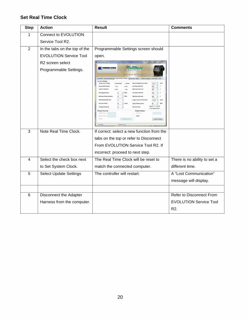
Set Real Time Clock
Step Action Result Comments
1 Connect to EVOLUTION
Service Tool R2.
2 In the tabs on the top of the
EVOLUTION Service Tool
R2 screen select
Programmable Settings.
Programmable Settings screen should
open.
3 Note Real Time Clock. If correct: select a new function from the
tabs on the top or refer to Disconnect
From EVOLUTION Service Tool R2. If
incorrect: proceed to next step.
4 Select the check box next
to Set System Clock.
The Real Time Clock will be reset to
match the connected computer.
There is no ability to set a
different time.
5 Select Update Settings The controller will restart. A “Lost Communication”
message will display.
6 Disconnect the Adapter
Harness from the computer.
Refer to Disconnect From
EVOLUTION Service Tool
R2.

21
Check Software Revision
Step Action Result Comments
1 Connect to EVOLUTION
Service Tool R2.
2 In the tabs on the top of the
EVOLUTION Service Tool
R2 screen select Software
Upgrade.
Software Upgrade screen should open.
3 Under Current Version,
note the installed
component software
revisions.
If correct: select a new function from the
tabs on the top or refer to Disconnect
From EVOLUTION Service Tool R2..
If incorrect: proceed to Upgrade System
Software.
Refer to Diagnostic Manual
Section 3, Software
Description.
Controller = 41.xx
HMI = 42.xx
TK Monitor = 43.xx
Upgrade System Software
Step Action Result Comments
1 Download software
upgrade ZIP file from
Thermo King Info Central.
Save software upgrade file to the PC
computer. Extract and save three
extracted files to a known location.
These will be the actual flash load files.
Recommendation: Create a
file folder dedicated to
TriPac EVOLUTION
software upgrade files.
2 Copy extracted flash load
files to the service
computer to be used for the
software update procedure
Refer to the Service Bulletin about the
planned software upgrade for actual
flash load file names.
Recommendation: Create a
file folder dedicated to
TriPac EVOLUTION
software upgrade files.
3 Connect to EVOLUTION
Service Tool R2.
Refer to Connect to
EVOLUTION Service Tool
R2.

22
Step Action Result Comments
4 In the tabs on top of the
EVOLUTION Service Tool
R2 screen select
Programmable Settings.
Record the current value of
the Programmable Settings.
Will be used to verify correct settings
after software upgrade.
Refer to Record or Setup
Programmable Settings.
5 In the tabs on the top of the
EVOLUTION Service Tool
R2 screen select Software
Upgrade.
Software Upgrade screen will open.
6 Verify current software
revisions to determine if a
software upgrade is
required.
Refer to Service Bulletin for
the planned software
upgrade.
7 Click the Select file button. A file search dialog box will open.
Locate the software upgrade files
extracted and saved in step 1.
NOTE: Only the software
for one component;
Controller, HMI or TK
Monitor can be flash loaded
at one time. Perform
upgrades in the following
order:
Controller
HMI
TK Monitor
8 Click Upgrade software
button to open the selected
software upgrade file.
Upgrade process will begin. NOTE: System will not
accept changes if Password
Protection is set to YES.
Enter password and retry.
9 A “Progress Bar” will be
visible on the Software
Upgrade screen.
Indicates progress of the flashloading
process.
Flash load of each
component should take 20
to 45 seconds. Green LED
may flash rapidly.

23
Step Action Result Comments
10 A “Software Upgrade
Complete” message will
display.
A prompt will display “Do you want to
upgrade another Software? Click Yes to
continue, No to restart.” If you click No,
“Lost Communication” will display. Click
OK.
NOTE: When HMI software
is updated, the controller
will turn off. You will have to
turn the system on by
pressing the HMI power
button.
11 EVOLUTION Service Tool
R2 will restart at the
Dashboard. Go to Software
Upgrade to verify updated
revision.
Software revision numbers should have
changed to the expected level.
Refer to Service Bulletin for
the planned software
upgrade.
12 Verify the value of the
Programmable Settings
match those previously
recorded.
Update programmable settings if
necessary.
Refer to Record or Setup
Programmable Features
and Unit Setup.
13 Verify proper unit operation.
14 Close EVOLUTION Service
Tool R2 or continue with
other tasks.
Refer to Disconnect From
EVOLUTION Service Tool
R2.
Operate Service Test Mode
Step Action Result Comments
Enter Service Test Mode
1 Connect to EVOLUTION
Service Tool R2.
2 In the tabs on the top of the
EVOLUTION Service Tool
R2 screen select Service
Test.
Service Test screen will open.
24
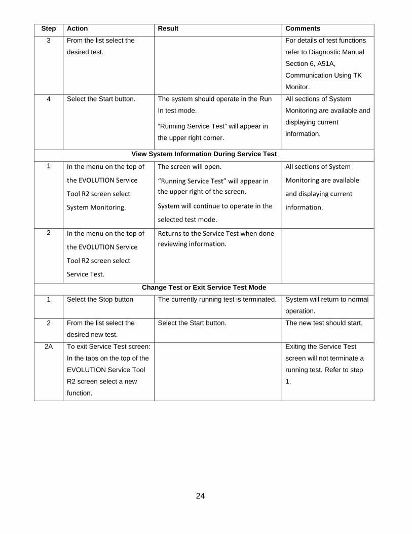
Step Action Result Comments
3 From the list select the
desired test.
For details of test functions
refer to Diagnostic Manual
Section 6, A51A,
Communication Using TK
Monitor.
4 Select the Start button. The system should operate in the Run
In test mode.
“Running Service Test” will appear in
the upper right corner.
All sections of System
Monitoring are available and
displaying current
information.
View System Information During Service Test
1 In the menu on the top of
the EVOLUTION Service
Tool R2 screen select
System Monitoring.
The screen will open.
“Running Service Test” will appear in
the upper right of the screen.
System will continue to operate in the
selected test mode.
All sections of System
Monitoring are available
and displaying current
information.
2 In the menu on the top of
the EVOLUTION Service
Tool R2 screen select
Service Test.
Returns to the Service Test when done
reviewing information.
Change Test or Exit Service Test Mode
1 Select the Stop button The currently running test is terminated. System will return to normal
operation.
2 From the list select the
desired new test.
Select the Start button. The new test should start.
2A To exit Service Test screen:
In the tabs on the top of the
EVOLUTION Service Tool
R2 screen select a new
function.
Exiting the Service Test
screen will not terminate a
running test. Refer to step
1.
25
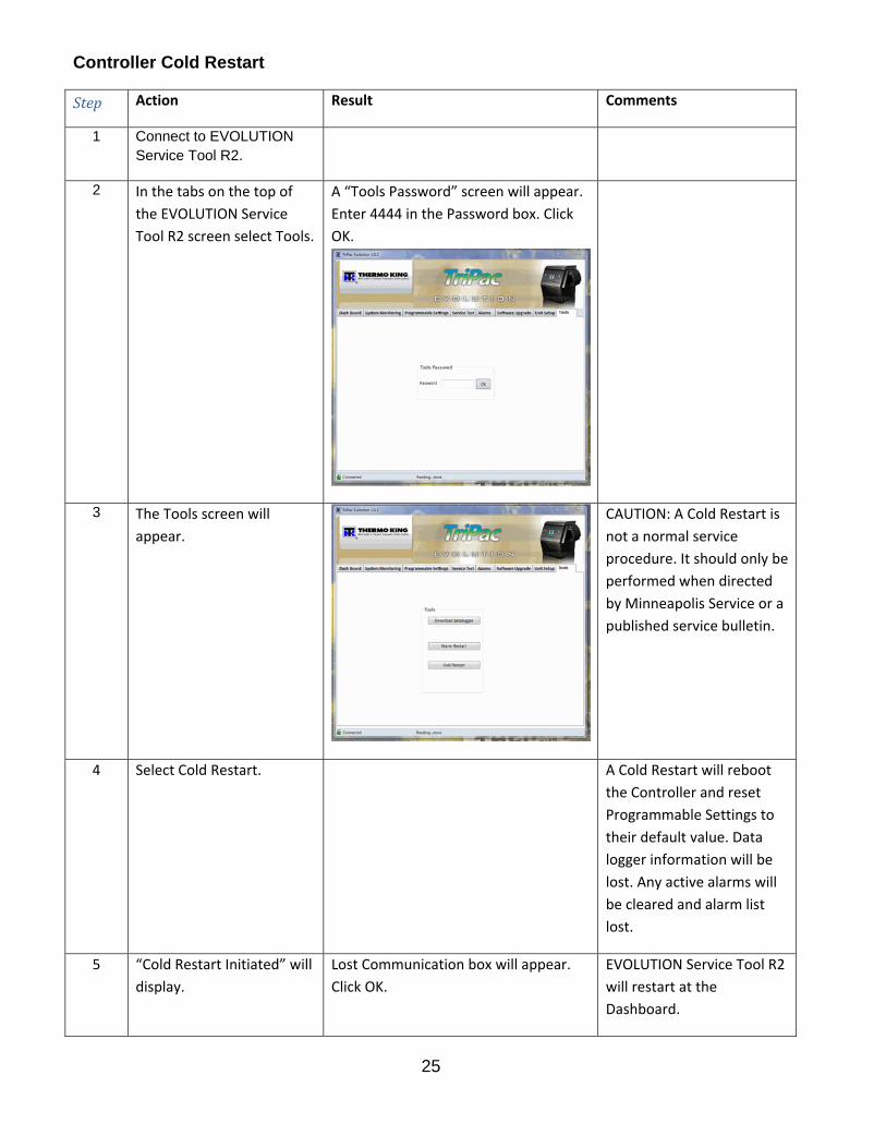
Controller Cold Restart
Step Action Result Comments
1 Connect to EVOLUTION Service Tool R2.
2 In the tabs on the top of
the EVOLUTION Service
Tool R2 screen select Tools.
A “Tools Password” screen will appear.
Enter 4444 in the Password box. Click
OK.
3 The Tools screen will
appear.
CAUTION: A Cold Restart is
not a normal service
procedure. It should only be
performed when directed
by Minneapolis Service or a
published service bulletin.
4 Select Cold Restart. A Cold Restart will reboot
the Controller and reset
Programmable Settings to
their default value. Data
logger information will be
lost. Any active alarms will
be cleared and alarm list
lost.
5 “Cold Restart Initiated” will
display.
Lost Communication box will appear.
Click OK.
EVOLUTION Service Tool R2
will restart at the
Dashboard.

26
Step Action Result Comments
6 Disconnect the Adapter
Harness from the
computer.
Refer to Disconnect From
EVOLUTION Service Tool
R2.
Download Datalogger
Step Action Result Comments
1 Connect to EVOLUTION Service Tool R2.
2 In the tabs on the top of
the EVOLUTION Service
Tool R2 screen select Tools.
A “Tools Password” screen will appear.
Enter 4444 in the Password box. Click
OK.
3 The Tools screen will
appear.
4 Select “Download
datalogger”
Downloading, please wait.
27
Step Action Result Comments
5 System will generate a
datalogger file.
Download complete. Please Warm Start
before next download.
The file will be a *.BIN file.
EVOLUTION Service Tool R2
cannot display these files. A
file converter is required.
See A50A.
6 A “Save Datalogger”
window will display.
Choose a file name and
save location.
File may be renamed with a short
descriptive name with no spaces. File
extension must remain .BIN. Save to a
location that you can find again.
Recommendation: Create a
file folder dedicated to
TriPac EVOLUTION data
logger files. Default file
name is TT4DLFxx.bin or the
Unit ID programmed during
Unit setup.
7 Click “Warm Restart”. Lost Communication box will appear.
Click OK.
EVOLUTION Service Tool R2 will restart in Dashboard.
8 Disconnect the Adapter
Harness from the
computer.
Refer to Disconnect From
EVOLUTION Service Tool
R2.
28
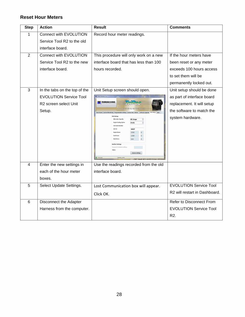
Reset Hour Meters
Step Action Result Comments
1 Connect with EVOLUTION
Service Tool R2 to the old
interface board.
Record hour meter readings.
2 Connect with EVOLUTION
Service Tool R2 to the new
interface board.
This procedure will only work on a new
interface board that has less than 100
hours recorded.
If the hour meters have
been reset or any meter
exceeds 100 hours access
to set them will be
permanently locked out.
3 In the tabs on the top of the
EVOLUTION Service Tool
R2 screen select Unit
Setup.
Unit Setup screen should open. Unit setup should be done
as part of interface board
replacement. It will setup
the software to match the
system hardware.
4 Enter the new settings in
each of the hour meter
boxes.
Use the readings recorded from the old
interface board.
5 Select Update Settings. Lost Communication box will appear.
Click OK.
EVOLUTION Service Tool
R2 will restart in Dashboard.
6 Disconnect the Adapter
Harness from the computer.
Refer to Disconnect From
EVOLUTION Service Tool
R2.
29
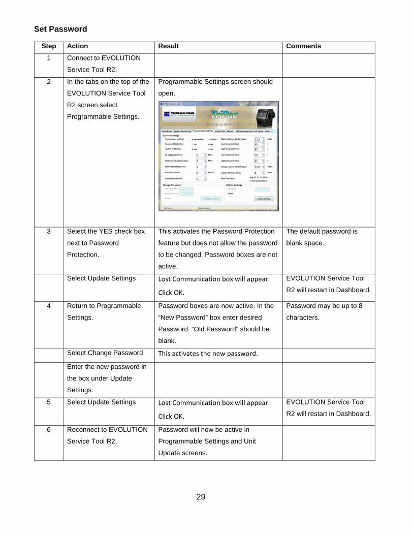
Set Password
Step Action Result Comments
1 Connect to EVOLUTION
Service Tool R2.
2 In the tabs on the top of the
EVOLUTION Service Tool
R2 screen select
Programmable Settings.
Programmable Settings screen should
open.
3 Select the YES check box
next to Password
Protection.
This activates the Password Protection
feature but does not allow the password
to be changed. Password boxes are not
active.
The default password is
blank space.
Select Update Settings Lost Communication box will appear.
Click OK.
EVOLUTION Service Tool
R2 will restart in Dashboard.
4 Return to Programmable
Settings.
Password boxes are now active. In the
“New Password” box enter desired
Password. “Old Password” should be
blank.
Password may be up to 8
characters.
Select Change Password This activates the new password.
Enter the new password in
the box under Update
Settings.
5 Select Update Settings Lost Communication box will appear.
Click OK.
EVOLUTION Service Tool
R2 will restart in Dashboard.
6 Reconnect to EVOLUTION
Service Tool R2.
Password will now be active in
Programmable Settings and Unit
Update screens.

30
Change Password
Step Action Result Comments
1 Connect to EVOLUTION
Service Tool R2.
2 In the tabs on the top of the
EVOLUTION Service Tool
R2 screen select
Programmable Settings.
Programmable Settings screen should
open.
4 Enter current password in
the “Old Password” box.
Password boxes are now active. In the
“New Password” box enter desired
Password. “Old Password” should be
blank.
Password may be up to 8
characters.
Enter new password in the
“New Password “box.
Select Change Password This activates the new password.
Enter the new password in
the box under Update
Settings.
5 Select Update Settings Lost Communication box will appear.
Click OK.
EVOLUTION Service Tool
R2 will restart in Dashboard.
6 Reconnect to EVOLUTION
Service Tool R2.
Password will now be active in
Programmable Settings and Unit
Update screens.

31
Bypass the Password
Step Action Result Comments
1 Connect to EVOLUTION Service Tool R2.
2 In the tabs on the top of the EVOLUTION Service Tool R2 screen select Programmable Settings.
Programmable Settings screen should
open.
3 The YES check box next to
Password Protection is
selected. A Password box is
active at the bottom of the
screen.
A password is required to make
changes to Programmable Settings or
Unit Setup values.
4 The password is not known
and is not available.
The password can only be bypassed by
performing a Cold Restart.
CAUTION: A Cold Restart will
return Programmable
Settings to default values,
erase the data logger and
erase alarm history
5 Record value of all
programmable settings.
Record all alarms. Download
the data logger.
Will be used to re‐enter customer
settings.

32
Step Action Result Comments
2 In the tabs on the top of the
EVOLUTION Service Tool R2
screen select Tools.
A “Tools Password” screen will appear.
Enter 4444 in the Password box. Click
OK.
3 The Tools screen will appear. CAUTION: A Cold Restart is
not a normal service
procedure. It should only be
performed when directed by
Minneapolis Service or a
published service bulletin.
4 Select Cold Restart. A Cold Restart will reboot
the Controller and reset
Programmable Settings to
their default value. Data
logger information will be
lost. Any active alarms will
be cleared and alarm list
lost.
5 “Cold Restart Initiated” will
display.
Lost Communication box will appear.
Click OK.
EVOLUTION Service Tool R2
will restart at the
Dashboard.
10 Go to Record or Setup
Programmable Settings
Make changes as required.
11 Go to Unit Setup. Verify correct settings.

33
Step Action Result Comments
12 Verify proper unit operation.
13 Disconnect the Adapter
Harness from the computer.
Refer to Disconnect From EVOLUTION Service Tool R2.