service graph design with cisco application centric ...® application centric infrastructure (cisco...
TRANSCRIPT

© 2017 Cisco and/or its affiliates. All rights reserved. This document is Cisco Public Information. Page 1 of 101
White Paper
Service Graph Design with Cisco Application Centric
Infrastructure

© 2017 Cisco and/or its affiliates. All rights reserved. This document is Cisco Public Information. Page 2 of 101
Contents
Introduction .............................................................................................................................................................. 4 When to Use the Service Graph ........................................................................................................................... 4 Service Insertion with Cisco ACI ........................................................................................................................... 7 Service Graphs, Functions, and Rendering .......................................................................................................... 7 L4-L7 Parameters ............................................................................................................................................... 10 Management Model ............................................................................................................................................ 12
Design Choices for Bridge Domains, VRF Instances, and EPGs ...................................................................... 14 Bridge Domain and VRF Provisioning ................................................................................................................. 14 Layer 2 and Layer 3 Forwarding in Cisco ACI..................................................................................................... 16 Bridge Domain Tuning Considerations ............................................................................................................... 17 Bridge Domain Tuning for Service Graph with Policy Based Redirect (PBR) ..................................................... 19 IP Routing Considerations .................................................................................................................................. 20 VRF Design Considerations for Go-To and Go-Through Mode Deployments .................................................... 23 Using L3Out for Routing to the L4-L7 Device...................................................................................................... 27 EPGs, Contracts, and Connectors ...................................................................................................................... 30
Device Selection Policy .................................................................................................................................. 31 Graph Connector Properties .......................................................................................................................... 31 Deploying the Graph Template on Multiple EPG Pairs ................................................................................... 32
Deployment Modes ................................................................................................................................................ 35 Routed Mode (Go-To Mode) ............................................................................................................................... 35
Routed Mode with L3Out and NAT ................................................................................................................. 36 Routed Mode with L3Out Routing to the L4-L7 Device .................................................................................. 37 Routed Mode with PBR to the L4-L7 Device .................................................................................................. 38
Transparent Mode (Go-Through Mode) .............................................................................................................. 40 Transparent Mode with Outside Layer 2 Bridge Domain ................................................................................ 41
One-Arm Mode ................................................................................................................................................... 42
Physical Topology Choices .................................................................................................................................. 43 Management Traffic ............................................................................................................................................ 44 Data Traffic ......................................................................................................................................................... 45 Physical Appliances (Managed Mode) ................................................................................................................ 45 Physical Appliances (Unmanaged Mode) ........................................................................................................... 46 Virtual Appliances (Managed Mode and Unmanaged Mode) .............................................................................. 46 Failover Traffic .................................................................................................................................................... 47
High-Availability Design and Configuration ........................................................................................................ 48 High-Availability Connectivity from the Physical Appliance to the Fabric ............................................................ 48 High-Availability Connectivity from the Virtual Appliance to the Fabric ............................................................... 49 Deploying Redundant Physical Appliances ......................................................................................................... 50
Primary Cisco ASA Configuration (Performed by Cisco APIC) ...................................................................... 52 Secondary Cisco ASA Configuration (Performed by Cisco APIC) .................................................................. 53 Failover Status (Primary) ................................................................................................................................ 54 Failover Status (Secondary) ........................................................................................................................... 54
Deploying Redundant Virtual Appliances ............................................................................................................ 55 Primary Cisco ASA Configuration (Performed by Cisco APIC) ...................................................................... 57 Secondary Cisco ASA Configuration (Performed by Cisco APIC) .................................................................. 58
Deploying Clustering for Physical Appliances (Cisco ASA Cluster) .................................................................... 58
Design for Sharing L4-L7 Appliances .................................................................................................................. 61 Multiple Tenants: Using a Cisco ASA Physical Appliance .................................................................................. 61 Multiple Tenants: Using an F5 BIG-IP Physical Appliance .................................................................................. 62 Sharing L4-L7 Devices with Another Tenant ....................................................................................................... 63
Example 1: Share Consumer Interface (Virtual Appliance) ............................................................................ 64 Example 2: DMZ (Virtual Appliance) .............................................................................................................. 66 Example 3: Share Consumer Interface (Physical Appliance) ......................................................................... 67

© 2017 Cisco and/or its affiliates. All rights reserved. This document is Cisco Public Information. Page 3 of 101
Service Graph and Function Profile Reuse ......................................................................................................... 69 Service Graph Template Reuse ..................................................................................................................... 70
L4-L7 Parameters Best Practices ......................................................................................................................... 72 Where L4-L7 Parameters Are Stored .................................................................................................................. 72 Defining Common Parameters ............................................................................................................................ 74
Sample Tenant Configuration ......................................................................................................................... 78
Example .................................................................................................................................................................. 89 Management Configuration on Cisco ASA and ASAv ......................................................................................... 89 Fabric and Access Policy Configuration .............................................................................................................. 89 Data Path Configuration for Transparent Mode .................................................................................................. 90 L4-L7 Parameters for Transparent Mode ............................................................................................................ 91 XML Configuration for Cisco ASAv Deployed in Transparent Mode ................................................................... 92
Creating the Tenant ........................................................................................................................................ 92 Creating the Contract ..................................................................................................................................... 92 Creating CDev and LDev ............................................................................................................................... 93 Creating the Service Graph Template ............................................................................................................ 94 Configuring Device Selection Policy ............................................................................................................... 96 Configuring the Provider EPG with L4-L7 Parameters ................................................................................... 97 Attaching the Graph to the Contract ............................................................................................................. 100
Conclusion ........................................................................................................................................................... 100
For More Information ........................................................................................................................................... 100

© 2017 Cisco and/or its affiliates. All rights reserved. This document is Cisco Public Information. Page 4 of 101
Introduction
Cisco®
Application Centric Infrastructure (Cisco ACI™
) technology enables you to insert Layer 4 through Layer 7
(L4-L7) functions using a concept called a service graph. This document describes the service graph concept and
how to design for service insertion using the service graph.
With the service graph, Cisco ACI introduces innovations at both the data-plane and management levels.
Using the service graph, Cisco ACI can redirect traffic between security zones to a firewall or a load balancer,
without the need for the firewall or the load balancer to be the default gateway for the servers. Cisco ACI can
selectively send traffic to L4-L7 devices based, for instance, on the protocol and the Layer 4 port. Firewall
inspection can be transparently inserted in a Layer 2 domain with almost no modification to existing routing and
switching configurations. Cisco ACI also allows you to increase the capacity of L4-L7 devices by creating a pool of
devices to which Cisco ACI can distribute traffic.
With the service graph, Cisco ACI introduces changes in the operation model. A configuration can now include not
only network connectivity—VLANs, IP addresses, and so on—but also the configuration of Access Control Lists
(ACLs), load-balancing rules, and so on.
This approach differs from the traditional operation model of service insertion. Prior to Cisco ACI, the fabric
configuration consisted only of connectivity for firewalls and load balancers. With Cisco ACI and the service
graph, it can include the configuration of firewalls and load balancers.
With the service graph, security and load-balancing administrators can define security and load-balancing policies
using the management tool of their preferred vendor. The Cisco Application Policy Infrastructure Controller (APIC)
administrator can then associate these policies with the traffic path that the administrator defined in Cisco ACI.
When to Use the Service Graph
You can deploy firewalls and load balancers with Cisco ACI with or without a service graph. To decide whether or
not you should use the service graph technology, you need to understand the problem that the service graph
solves and the available operational models.
Cisco designed the service graph technology to automate the deployment of an L4-L7service in the network. Cisco
ACI doesn’t provision the L4-L7 device itself, but it can configure it as part of the same configuration that creates
tenants, bridge domains, and Endpoint Groups (EPGs).
Cisco ACI offers three management models for the service graph:
● Network policy mode (or unmanaged mode): In this mode, Cisco ACI configures only the network portion of
the service graph on the Cisco ACI fabric, which means that Cisco ACI doesn't push configurations to the
L4-L7 device.
● Service policy mode (or managed mode): In this mode, Cisco ACI configures the fabric and the L4-L7
device VLANs, and the APIC administrator enters the L4-L7 device configurations through APIC.
● Service manager mode: In this mode, the firewall or load-balancer administrator defines the L4-L7 policy,
Cisco ACI configures the fabric and the L4-L7 device VLANs, and the APIC administrator associates the L4-
L7 policy with the networking policy.

© 2017 Cisco and/or its affiliates. All rights reserved. This document is Cisco Public Information. Page 5 of 101
You may find the service graph useful if you want to create a portal from which administrators can create and
decommission network infrastructure, including firewalls and load balancers. In this case, Cisco ACI can help
automate the configuration of the firewalls and load balancers so long as they already exist as either physical or
virtual devices. For this use case, you may want to use the service policy mode or service manager mode.
With the service graph in service policy mode, the configuration of the L4-L7 device is part of the configuration of
the entire network infrastructure, so you need to consider the security and load-balancing rules at the time that you
configure network connectivity for the L4-L7 device. This approach is different from that of traditional service
insertion in that if you don’t use the service graph, you can configure the security and load-balancing rules at a
different time than when you configure network connectivity.
With the service manager mode, the interactions with the L4-L7 device depend on the vendor management tool.
Cisco ACI references a policy defined on the L4-L7 management tool. This tool may let you make changes to the
firewall or load-balancer configurations without the need to redeploy the service graph.
If all you need is a topology with a perimeter firewall that controls access to the data center, and if this firewall is
not decommissioned and provisioned again periodically, you should use the network policy mode deployment.
The service graph concept is considered an extension to the concept of a contract, so by default it operates with
the model of an external and an internal interface. If you need to use the service graph for a firewall with multiple
network edges (or DMZs), you need to reuse the service graph multiple times between each pair of interfaces.
For this type of deployment you may find it more convenient to integrate the firewall without using the service
graph.
The service graph offers several advantages and some disadvantages. Two of the biggest advantages are the
capability to redirect traffic (which works in all deployment modes: network policy mode, service policy mode, and
service manager mode) and the capability to automate VLAN allocation between the L4-L7 device and the fabric.
Service graph redirect offers many advantages:
● It eliminates the need to make the firewall or load balancers the default gateway.
● It avoids the need for more complex types of designs such as the Virtual Routing and Forwarding (VRF)
instance–L4-L7–VRF design.
● It avoids to need to split Layer 2 domains (bridge domains) to insert, for instance, a firewall in the path.
● It allows you to redirect only a subset of the traffic based on the protocol and port.
● It allows you to filter traffic between security zones in the same Layer 2 domain (bridge domain).
● It allows you to scale the performance of the L4-L7 device by distributing traffic to multiple devices.
The service graph offers these advantages:
● The service graph can redirect traffic to L4-L7 devices, eliminating the need for more complex designs.
● The service graph automatically manages VLAN assignments.
● The service graph automatically connects virtual Network Interface Cards (vNICs).
● The configuration template can be reused multiple times.
● The service graph provides a more logical view and offers an application-related view of services.
● The service graph provides a better model for sharing a device across multiple departments.
● The service graph collects health scores from the device or service.

© 2017 Cisco and/or its affiliates. All rights reserved. This document is Cisco Public Information. Page 6 of 101
● The service graph collects statistics from the device.
● The service graph updates ACLs and pools automatically with endpoint discovery.
The service graph in service policy mode has some disadvantages:
● The operational model is orientated toward automation.
● The number of configuration parameters that the APIC administrator needs to manage can be
overwhelming and not practical for deployments that require frequent configuration adjustments.
In summary, when choosing whether to use a service graph or traditional bridge-domain stitching, you need to take
into account the following points:
● Do I need the firewall and load balancers to be configured dynamically through the APIC, or should a
different administrator configure them? In the second case, you should use network policy mode or service
manager mode.
● Do I need to be able to commission, use, and decommission a firewall or a load balancer frequently, as in a
cloud service, or will these services be used in the same way for a long period of time? In the first case, you
should use service policy mode or service manager mode. In the second case, you should use network
policy mode or service manager mode.
● Does my design require only two interfaces for load balancers and firewalls, or does it require a multiple-leg
and multiple-DMZ configuration? In the second case, you may find it more convenient not to use the service
graph, but to instead perform service insertion based on manual configuration of EPGs and bridge domains.
The flowchart in Figure 1 shows how to choose the service graph deployment method.
Figure 1. Service Graph Decision Flowchart

© 2017 Cisco and/or its affiliates. All rights reserved. This document is Cisco Public Information. Page 7 of 101
Service Insertion with Cisco ACI
In Cisco ACI, you also can configure service insertion without a service graph.
To do so, you need to create multiple bridge domains that operate just like VLANs, and you can configure EPGs to
connect virtual or physical appliances.
Figure 2 shows a simple multinode service insertion design. The configuration consists of multiple bridge domains
and EPGs. Bridge Domain 1 has an EPG to which the router and the firewall outside interface connect. Bridge
Domain 2 has one EPG to connect the inside interface of the firewalls and the client-side interface of the
Application Delivery Controller (ADC) device. Bridge Domain 3 has an EPG for the server-side interface of the ADC
device and multiple EPGs for the servers, and the EPGs are connected through contracts.
Figure 2. Manual Configuration of Service Insertion
Service Graphs, Functions, and Rendering
The concept of a service graph differs from the concept of service insertion. The service graph specifies that the
path from one EPG to another EPG must pass through certain functions:
● With service graph redirect, the service graph effectively steers traffic to the L4-L7 device.
● With the other service graph deployment modes, the service graph doesn't steer traffic to the L4-L7 device,
but it creates contracts to prevent the traffic from going directly from one EPG to the other. Only traffic that
goes through the L4-L7 device is allowed.
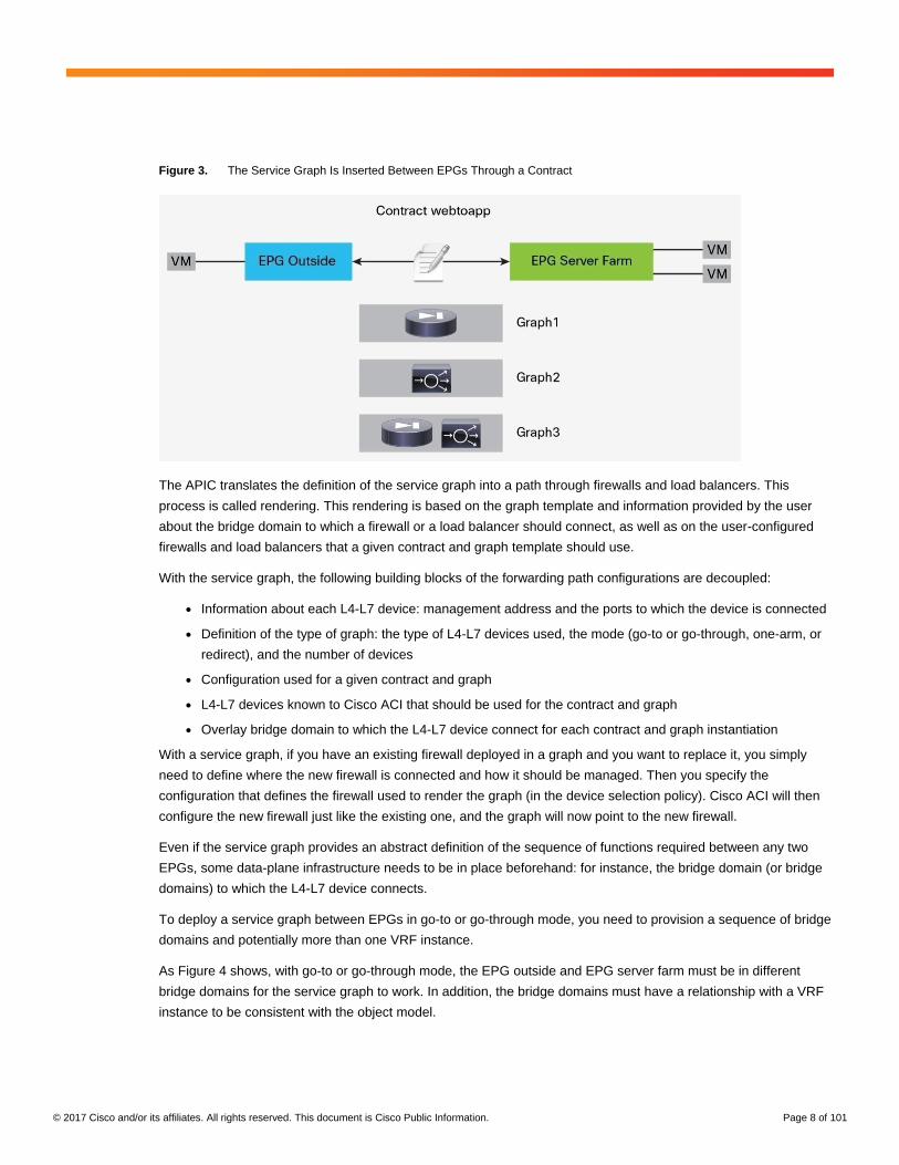
As Figure 3 illustrates, the service graph is associated with a contract between two EPGs. In the figure, the
contract webtoapp can be associated with Graph1, which consists of a single firewall device; or with Graph2, which
consists of a single ADC device; or with Graph3, which consists of a sequence of a firewall and an ADC device.
A contract could also have a single contract with multiple "subjects" (that is, combinations of Layer 4 ports), each
associated with a different graph.
© 2017 Cisco and/or its affiliates. All rights reserved. This document is Cisco Public Information. Page 8 of 101
Figure 3. The Service Graph Is Inserted Between EPGs Through a Contract
The APIC translates the definition of the service graph into a path through firewalls and load balancers. This
process is called rendering. This rendering is based on the graph template and information provided by the user
about the bridge domain to which a firewall or a load balancer should connect, as well as on the user-configured
firewalls and load balancers that a given contract and graph template should use.
With the service graph, the following building blocks of the forwarding path configurations are decoupled:
● Information about each L4-L7 device: management address and the ports to which the device is connected
● Definition of the type of graph: the type of L4-L7 devices used, the mode (go-to or go-through, one-arm, or
redirect), and the number of devices
● Configuration used for a given contract and graph
● L4-L7 devices known to Cisco ACI that should be used for the contract and graph
● Overlay bridge domain to which the L4-L7 device connect for each contract and graph instantiation
With a service graph, if you have an existing firewall deployed in a graph and you want to replace it, you simply
need to define where the new firewall is connected and how it should be managed. Then you specify the
configuration that defines the firewall used to render the graph (in the device selection policy). Cisco ACI will then
configure the new firewall just like the existing one, and the graph will now point to the new firewall.
Even if the service graph provides an abstract definition of the sequence of functions required between any two
EPGs, some data-plane infrastructure needs to be in place beforehand: for instance, the bridge domain (or bridge
domains) to which the L4-L7 device connects.
To deploy a service graph between EPGs in go-to or go-through mode, you need to provision a sequence of bridge
domains and potentially more than one VRF instance.
As Figure 4 shows, with go-to or go-through mode, the EPG outside and EPG server farm must be in different
bridge domains for the service graph to work. In addition, the bridge domains must have a relationship with a VRF
instance to be consistent with the object model.

© 2017 Cisco and/or its affiliates. All rights reserved. This document is Cisco Public Information. Page 9 of 101
Figure 4. With the L4-L7 Device in Go-To or Go-Through Mode, EPGs Must Be in Different Bridge Domains
The rendering involves allocation of the necessary VLANs between the L4-L7 device and the bridge domains, and
the forwarding mode of the bridge domains must be compatible with the forwarding mode of the L4-L7 device.
Cisco ACI creates EPGs to which the L4-L7 device connects, and it creates contracts to enable communication to
and from the L4-L7 device (Figure 5).
Figure 5. ACI Creates Shadow EPGs and Contracts to Allow Communication with the L4-L7 Device
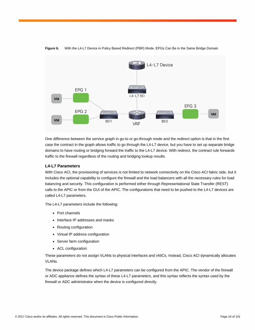
When you use service graph redirect, the L4-L7 device doesn't need to be connected directly to the bridge domains
in which the endpoints reside. In addition, the endpoints do not need to be in different bridge domains for the traffic
to traverse a L4-L7 device. Figure 6 shows a firewall connected to the L4-L7 bridge domain. Virtual machines are
on BD1 and BD2. With service graph redirect, you can configure traffic from EPG1 to EPG2 to be sent through the
firewall first, as well as traffic from EPG1 or EPG 2 to EPG3. You can also define a rule that says that only traffic on
port 80 between EPG1 and EPG2 has to go through the firewall, whereas other traffic can go directly between
EPG1 and EPG2.
© 2017 Cisco and/or its affiliates. All rights reserved. This document is Cisco Public Information. Page 10 of 101
Figure 6. With the L4-L7 Device in Policy Based Redirect (PBR) Mode, EPGs Can Be in the Same Bridge Domain
One difference between the service graph in go-to or go-through mode and the redirect option is that in the first
case the contract in the graph allows traffic to go through the L4-L7 device, but you have to set up separate bridge
domains to have routing or bridging forward the traffic to the L4-L7 device. With redirect, the contract rule forwards
traffic to the firewall regardless of the routing and bridging lookup results.
L4-L7 Parameters
With Cisco ACI, the provisioning of services is not limited to network connectivity on the Cisco ACI fabric side, but it
includes the optional capability to configure the firewall and the load balancers with all the necessary rules for load
balancing and security. This configuration is performed either through Representational State Transfer (REST)
calls to the APIC or from the GUI of the APIC. The configurations that need to be pushed to the L4-L7 devices are
called L4-L7 parameters.
The L4-L7 parameters include the following:
● Port channels
● Interface IP addresses and masks
● Routing configuration
● Virtual IP address configuration
● Server farm configuration
● ACL configuration
These parameters do not assign VLANs to physical interfaces and vNICs. Instead, Cisco ACI dynamically allocates
VLANs.
The device package defines which L4-L7 parameters can be configured from the APIC. The vendor of the firewall
or ADC appliance defines the syntax of these L4-L7 parameters, and this syntax reflects the syntax used by the
firewall or ADC administrator when the device is configured directly.

© 2017 Cisco and/or its affiliates. All rights reserved. This document is Cisco Public Information. Page 11 of 101
The configuration of L4-L7 parameters from the APIC can be tedious, so Cisco ACI provides the function profile
feature, which allows you to define a collection of L4-L7 parameters that you can use when you apply a service
graph template. Function profiles can also be prepopulated by the management system of the L4-L7 device
vendor.
When you use the service graph function of Cisco ACI in service policy mode, you enter all the configurations for
the fabric and for the service device as part of the same L4-L7 configuration process. As a result, you must enter
L4-L7 parameters that configure the firewall and the load balancer. This process can be time consuming,
particularly if you want to decommission a device and redeploy it in a different way. The function profile solves this
problem.
With a function profile, you can create a collection of L4-L7 configuration parameters that you can use when you
apply a service graph template.
If you are using the service graph with a device package, the APIC communicates with the L4-L7 device to
configure it as part of the rendering of the graph.
The APIC communicates with the firewalls or load balancers to render the graph defined by the user. For Cisco
ACI to be able to talk to firewalls and load balancers, it needs to speak to their APIs. The administrator needs to
install plug-ins called device packages on the APIC to enable this communication.
As shown in Figure 7, the device package includes a description of the device and lists the parameters it is
exposing for the APIC configuration. The device package includes the scripts that allow Cisco ACI to talk to this
device.
Figure 7. The Device Package Enables Communication from Cisco APIC to the L4-L7 Device

© 2017 Cisco and/or its affiliates. All rights reserved. This document is Cisco Public Information. Page 12 of 101
With the device package, the vendor of the L4-L7 device makes certain settings configurable through the APIC. For
instance, these settings may be the most used functions of the L4-L7 device. With this type of device package, the
L4-L7 device can be configured almost entirely from the APIC. An example of such an implementation is the Cisco
Adaptive Security Appliance (ASA) device package with policy orchestration and fabric insertion.
The APIC will clear any device global configuration that is supported from APIC that has not been pushed from
the APIC. For instance, the APIC does not clear the management IP address, login credentials, or any
configuration that the device needs to be operational that is not supported through the APIC.
Certain device packages make only network configurations available through the APIC, leaving L4-L7
configurations to be managed directly on the device. An example of this type of device package is the Cisco ASA
device package that allows fabric insertion only.
Management Model
The service graph introduces multiple operational models for deploying L4-L7 services.
The service graph in network policy mode follows a traditional operational model in which the configuration of L4-
L7 devices consists of the following steps:
● The network administrator configures the ports and VLANs to connect the firewall or the load balancer.
● The firewall administrator configures the ports and VLANs.
● The firewall administrator configures the ACLs and other components.
As shown in Figure 8, with the Cisco ACI service graph in network policy mode, the network administrator
configures the fabric but not necessarily the firewall.
Figure 8. Cisco ACI Service Graph with the Network Policy Mode Deployment Type: The Network Administrator Manages the Fabric but Not the Firewall or Load Balancer
In addition, with the Cisco ACI service graph in network policy mode, the security administrator administers the
firewall through a management tool designed for the L4-L7 device (Figure 9).

© 2017 Cisco and/or its affiliates. All rights reserved. This document is Cisco Public Information. Page 13 of 101
Figure 9. With the Network Policy Mode, the Security Administrator Manages the Firewall Directly or Through a Management Tool
With the Cisco ACI service graph in service policy mode, the management model changes as illustrated in Figure
10.
The network administrator needs to apply the configuration for the network as well as for the firewall through the
APIC, and the L4-L7 administrator needs to provide the L4-L7 configuration to the network administrator. This
configuration is then assembled as a function profile.
The APIC then programs both the fabric and the L4-L7 device. The L4-L7 administrator can read the configuration
from the L4-L7 management tool but cannot make changes to the configuration directly.
Figure 10. Cisco ACI Operational Model with Service Policy Mode: Network and L4-L7 Configuration Are Managed Through APIC
With the Cisco ACI service graph in service manager mode, the L4-L7 administrator defines the L4-L7
configurations through the L4-L7 management tool instead of configuring function profiles with L4-L7 parameters.
The APIC administrator configures the service graph and references the L4-L7 policy defined by the L4-L7
administrator. Figure 11 illustrates this concept.

© 2017 Cisco and/or its affiliates. All rights reserved. This document is Cisco Public Information. Page 14 of 101
Figure 11. Cisco ACI Operational Model with Service Manager Mode
Design Choices for Bridge Domains, VRF Instances, and EPGs
When deploying a service graph, you can choose among options such as the following:
● Transparent mode: Deploy the L4-L7 device in transparent mode when the L4-L7 device is bridging the two
bridge domains. In Cisco ACI, this mode is called go-through mode.
● Routed mode: Deploy the L4-L7 device in routed mode when the L4-L7 device is routing between the two
bridge domains. In Cisco ACI, this mode is called go-to mode.
● One-arm mode: Deploy the L4-L7 device in one-arm mode when a load balancer is located on a dedicated
bridge domain with one single interface.
● Policy Based Redirect (PBR): Deploy the L4-L7 device on a separate bridge domain than the clients or the
servers and redirect traffic to it based on protocol and port number.
Your first design choice is to identify the number of bridge domains and VRF instances that you need and the
number of EPGs and contracts.
Bridge Domain and VRF Provisioning
Typically, you need to provision one bridge domain for the outside (or client-side or consumer-side) interface, and
one bridge domain for the inside (or server-side or provider-side) interface.
Bridge domains have many configurable options. The main choices that you need to make are whether to enable
the following:
● Unknown unicast flooding or hardware proxy
● Address Resolution Protocol (ARP) flooding
● Routing
● Subnet IP address
© 2017 Cisco and/or its affiliates. All rights reserved. This document is Cisco Public Information. Page 15 of 101
The next section discusses how to tune these options to optimize flooding.
The default configuration, which works for most deployments, sets the parameters as follows:
● Unknown unicast flooding
● ARP flooding
● No routing (except if this bridge domain needs to be the default gateway for the servers or for the L4-L7
device)
● No subnet (except if this bridge domain needs to be the default gateway for the servers or for the L4-L7
device)
Each bridge domain also requires a relationship to a VRF instance. Whether you should allocate one or two VRF
instances depends on your design choice.
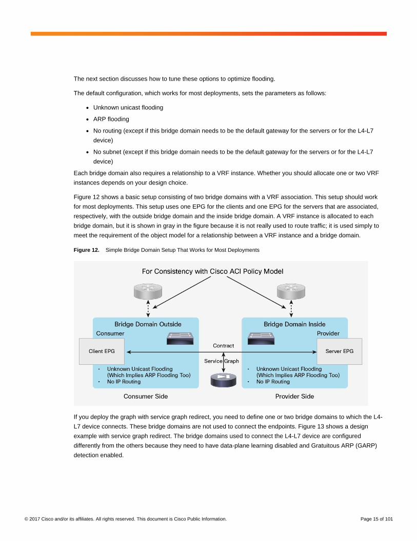
Figure 12 shows a basic setup consisting of two bridge domains with a VRF association. This setup should work
for most deployments. This setup uses one EPG for the clients and one EPG for the servers that are associated,
respectively, with the outside bridge domain and the inside bridge domain. A VRF instance is allocated to each
bridge domain, but it is shown in gray in the figure because it is not really used to route traffic; it is used simply to
meet the requirement of the object model for a relationship between a VRF instance and a bridge domain.
Figure 12. Simple Bridge Domain Setup That Works for Most Deployments
If you deploy the graph with service graph redirect, you need to define one or two bridge domains to which the L4-
L7 device connects. These bridge domains are not used to connect the endpoints. Figure 13 shows a design
example with service graph redirect. The bridge domains used to connect the L4-L7 device are configured
differently from the others because they need to have data-plane learning disabled and Gratuitous ARP (GARP)
detection enabled.

© 2017 Cisco and/or its affiliates. All rights reserved. This document is Cisco Public Information. Page 16 of 101
Figure 13. Bridge Domain Setup for Service Graph with Policy Based Redirect (PBR)
Layer 2 and Layer 3 Forwarding in Cisco ACI
Cisco ACI forwards traffic by using Virtual Extensible LAN (VXLAN) encapsulation. The way that packets are sent
to the VXLAN Tunnel Endpoint (VTEP) at which the destination MAC or IP address is located depends on the
bridge domain settings. Cisco ACI can forward traffic based on either the destination MAC address of the packet
prior to VXLAN encapsulation or the destination IP address of the packet prior to VXLAN encapsulation.
In Cisco ACI, routed traffic is traffic whose destination MAC address is the router MAC address: that is, the subnet
MAC address in the bridge domain. Layer 2, or bridged, traffic is traffic whose destination MAC address is not the
router MAC address.
Layer 2 traffic forwarding can be based on the MAC address–to–VTEP mapping learned as a result of flooding
along the multicast tree of each bridge domain, or it can be based on the mapping database that discovers
endpoints. The first forwarding mechanism is the classic VXLAN forwarding approach. It is enabled by setting the
bridge domain to perform unknown unicast flooding. With the second mechanism, the leaf switch discovers new
endpoints and populates the mapping database. The MAC address–to–VTEP mapping information is always
maintained in the mapping database that is stored in the spine proxy switch. If you want the Layer 2 forwarding to
be based on the mapping database, you need to enable the hardware-proxy option.
Routed traffic always is forwarded based on the mapping database. This approach requires a lookup of the IP
address–to–VTEP mapping information. The endpoint IP address is learned through the leaf switch. The leaf
switch discovers the endpoint IP address from the ARP requests of the endpoint or from the data-plane traffic from
an endpoint that is sending traffic to the destination MAC address of the router.
Note: This behavior can be disabled in the bridge domain, but this should be done only for a L4-L7 bridge
domain used with service graph redirect.

© 2017 Cisco and/or its affiliates. All rights reserved. This document is Cisco Public Information. Page 17 of 101
When routing is configured on the bridge domain, the bridge domain learns the IP addresses of the endpoints
regardless of the subnet to which their IP address belongs. You should and can configure the bridge domain to
learn only the IP addresses of the endpoints that belong to the subnet defined in the bridge domain as a default
gateway. This option is called Limit IP Learning to Subnet or Subnet Check.
In summary, the following configurations enable the use of the mapping database for forwarding:
● Hardware-proxy: Enables the use of the MAC address–to–VTEP database for Layer 2 forwarding
● IP routing: Enables the learning of the IP address–to–VTEP mapping and the use of the IP address–to–
VTEP database for Layer 3 forwarding
The example in Figure 14 shows where Cisco ACI performs Layer 2 forwarding and where it performs Layer 3
forwarding.
In BD3, the default gateway for the servers is the load balancer; hence, traffic is switched at Layer 2. In BD2, the
next hop of the load balancer for outbound traffic is the firewall, and the next hop of the firewall for inbound traffic is
the load balancer, so traffic is switched at Layer 2. On BD1, if a subnet is configured in the bridge domain and the
default gateway for the firewall is the bridge domain subnet IP address, then traffic is switched at Layer 3.
Note: If Limit IP Learning to Subnet is not enabled on BD1, the mapping database can learn the IP addresses of
the endpoints from BD3 as if they were in BD1.
Figure 14. Service Graph Example Showing on Which Bridge Domains Cisco ACI Performs Layer 2 and Layer 3 Forwarding
Bridge Domain Tuning Considerations
You can tune the bridge domain to reduce the amount of flooding in the domain. Two main options are available to
reduce flooding:
● Hardware proxy (instead of unknown unicast flooding): This option forwards bridged unknown unicast MAC
addresses to the spine-proxy database. This option provides benefits only in the event of bridged traffic.
This option has no influence on routed traffic (that is, traffic in which the destination MAC address is the BD
MAC address).
● No ARP flooding: This option transforms broadcast ARP requests into unicast packets. For this feature to
work, you need to enable IP routing because the mapping database must be populated with the IP
addresses of the endpoints. Hardware proxy must be enabled too.

© 2017 Cisco and/or its affiliates. All rights reserved. This document is Cisco Public Information. Page 18 of 101
In deciding whether to use these features, consider the following:
● Some L4-L7 devices in transparent (go-through) mode rely on flooding to build the forwarding tables just
like a transparent bridge does.
● When a L4-L7 device fails over, the IP address of that device may or may not change the MAC address too.
If it does change the MAC address, the Gratuitous ARP (GARP) traffic generated by the L4-L7 device must
reach the ARP cache of the adjacent devices. For this to happen, ARP flooding must be enabled (that is,
the ARP flooding optimization option must be off).
You can decide whether to use these features to reduce flooding with the L4-L7 device that you are using.
However, if you deploy a service graph in go-through mode, Cisco ACI automatically changes the bridge domain
settings to enable unknown unicast flooding and ARP flooding. In other words, with go-through mode Cisco ACI
doesn’t try to optimize flooding on the bridge domains attached to the L4-L7 device. Therefore, if you use a service
graph deployment (managed or unmanaged), you can choose whether to optimize flooding only when you are
using the go-to mode.
Assuming a service graph deployment with L4-L7 devices in go-to mode, you also need to consider where flood
removal would provide some benefits. Figure 15 illustrates this point. The figure shows a multinode graph. Flooding
optimization is useful on BD3 because it has several virtual machines and servers connected to it. The usefulness
of flooding optimization on BD1 and BD2 is negligible because BD1 has only the firewall interface and potentially a
router interface, and BD2 has only the interfaces of the firewall and the load balancer. Therefore, the only bridge
domain for which you may want to optimize flooding is BD3.
Figure 15. Scenarios in Which Hardware Proxy Provides Benefits
You may want to enable hardware proxy on BD3 and maybe on BD1 (if many client virtual machines are connected
to BD1), you need to decide whether to optimize unknown unicast MAC address flooding and also ARP flooding.
Figure 16 shows where ARP flooding is needed. With hardware proxy and no ARP flooding, GARP traffic for
firewall or load-balancer failover is not flooded. If a service device fails over, the endpoints don’t see the update of
the IP address–to–MAC address mapping. This behavior may be acceptable if the L4-L7 device allows you to
configure the same MAC address for both L4-L7 devices in the high-availability pair; otherwise, you need to keep
ARP flooding enabled.

© 2017 Cisco and/or its affiliates. All rights reserved. This document is Cisco Public Information. Page 19 of 101
Figure 16. Tuning ARP Flooding
The capability to disable ARP flooding depends on the configuration of hardware proxy and IP routing as follows:
● If hardware proxy is turned off, then ARP flooding is on and cannot be turned off.
● If hardware proxy is turned on but IP routing is turned off, ARP flooding is on and cannot be turned off.
● If hardware proxy is turned on and IP routing is turned on, then you can disable ARP flooding.
You may consider ARP flooding to be necessary because of silent hosts, but this is not completely true. It is true
that disabling ARP flooding requires the mapping database to know the endpoint IP address, and for this IP routing
must be turned on. But even if the endpoint had been silent, Cisco ACI can resolve the endpoint IP address by
sending ARP messages from the subnet IP address of the bridge domain. This feature is called ARP gleaning, and
it requires the bridge domain to be configured with a subnet IP address.
In summary, if you want to reduce ARP flooding (you can’t completely remove it all the time), you need to configure
the bridge domain as follows:
● Hardware proxy must be turned on.
● The ARP flooding option must be disabled.
● IP routing must be turned on.
● The subnet IP address must be configured.
● You should use Limit IP Learning to Subnet (also called Subnet Check)
For most deployments, you should keep ARP flooding on.
Bridge Domain Tuning for Service Graph with Policy Based Redirect (PBR)
When you use service graph redirect, the L4-L7 device is not directly connected to the endpoints. Therefore, the
configuration of the bridge domains to which the virtual machines or the physical servers are connected (BD1 and
BD2 in Figure 17) can be performed without having to consider the requirements of the L4-L7 device. In most
cases, you can use hardware proxy, and in certain cases you can also optimize ARP flooding.
The bridge domain that connects to the L4-L7 device must instead be configured as follows:
● IP routing should be enabled.
● Subnet should be configured.
● GARP-based detection should be on.
● Data-plane learning should be disabled.
© 2017 Cisco and/or its affiliates. All rights reserved. This document is Cisco Public Information. Page 20 of 101
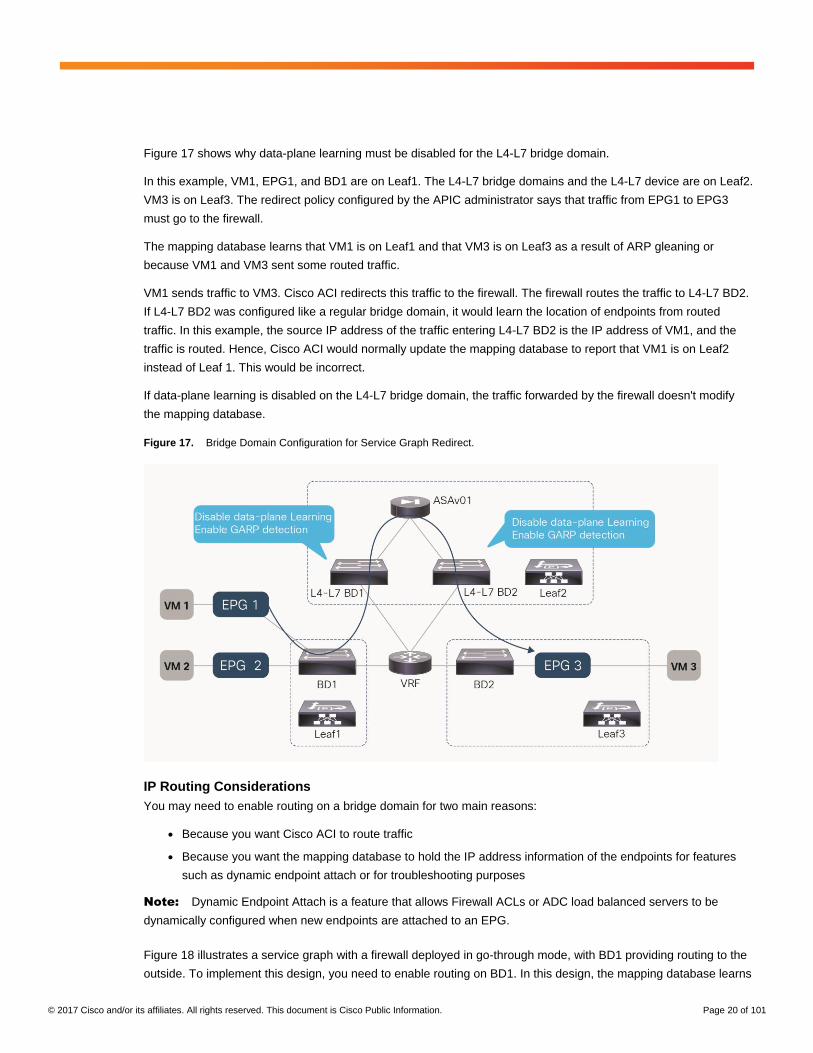
Figure 17 shows why data-plane learning must be disabled for the L4-L7 bridge domain.
In this example, VM1, EPG1, and BD1 are on Leaf1. The L4-L7 bridge domains and the L4-L7 device are on Leaf2.
VM3 is on Leaf3. The redirect policy configured by the APIC administrator says that traffic from EPG1 to EPG3
must go to the firewall.
The mapping database learns that VM1 is on Leaf1 and that VM3 is on Leaf3 as a result of ARP gleaning or
because VM1 and VM3 sent some routed traffic.
VM1 sends traffic to VM3. Cisco ACI redirects this traffic to the firewall. The firewall routes the traffic to L4-L7 BD2.
If L4-L7 BD2 was configured like a regular bridge domain, it would learn the location of endpoints from routed
traffic. In this example, the source IP address of the traffic entering L4-L7 BD2 is the IP address of VM1, and the
traffic is routed. Hence, Cisco ACI would normally update the mapping database to report that VM1 is on Leaf2
instead of Leaf 1. This would be incorrect.
If data-plane learning is disabled on the L4-L7 bridge domain, the traffic forwarded by the firewall doesn't modify
the mapping database.
Figure 17. Bridge Domain Configuration for Service Graph Redirect.
IP Routing Considerations
You may need to enable routing on a bridge domain for two main reasons:
● Because you want Cisco ACI to route traffic
● Because you want the mapping database to hold the IP address information of the endpoints for features
such as dynamic endpoint attach or for troubleshooting purposes
Note: Dynamic Endpoint Attach is a feature that allows Firewall ACLs or ADC load balanced servers to be
dynamically configured when new endpoints are attached to an EPG.
Figure 18 illustrates a service graph with a firewall deployed in go-through mode, with BD1 providing routing to the
outside. To implement this design, you need to enable routing on BD1. In this design, the mapping database learns

© 2017 Cisco and/or its affiliates. All rights reserved. This document is Cisco Public Information. Page 21 of 101
the IP addresses of the endpoints attached to BD2 as if they were in BD1. The MAC addresses of the endpoints
that are in BD2 are learned on both BD1 and BD2.
Figure 18. Enabling Routing on a Bridge Domain to Route the Traffic to the Outside
You also may want to enable routing on the bridge domain to which the servers are attached. You may want to do
this not because you want the bridge domain to be the default gateway, but because the mapping database needs
to learn the IP addresses of the servers. Figure 19 illustrates this use case.
The mapping database in BD3 learns the endpoint IP addresses from the ARP requests originated by the hosts.
No data-plane learning of the host IP addresses happens because the traffic is destined for the MAC address of
the load balancer.
Figure 19. Enabling Routing on the Server-Side Bridge Domain to Use Endpoint Attachment
When enabling routing, keep in mind that you must enable it in two places in the service graph:
● The bridge domain
● The graph connector

© 2017 Cisco and/or its affiliates. All rights reserved. This document is Cisco Public Information. Page 22 of 101
Figure 20 illustrates this point.
Figure 20. When Enabling Routing on a Bridge Domain, Make Sure That the Graph Template Connectors Are Set for Routing
In general, these connectors are set to unicast routing by default. This setting makes the final state of the bridge
domain dependent only on the routing configuration on the bridge domain.
If the connector is associated with a bridge domain that provides the Layer 3 outside (L3Out) interface function, in
addition to verifying that the unicast routing option is set to true, you need to make sure that the adjacency is set to
Layer 3, not Layer 2, as in Figure 21.
Figure 21. To Help Ensure That the Switch Virtual Interface Is Enabled on the Bridge Domain with L3Out, Set Adjacency to Layer 3
In summary, IP routing may be necessary in bridge domains that meet the following criteria:
● Bridge domains that provide routing to bridge domains that provide routing to another bridge domain or to
the outside
● Bridge domains to which servers are connected, if you plan to use endpoint attachment

© 2017 Cisco and/or its affiliates. All rights reserved. This document is Cisco Public Information. Page 23 of 101
VRF Design Considerations for Go-To and Go-Through Mode Deployments
In Cisco ACI, every bridge domain must have a relationship to a VRF instance. The question is whether the same
VRF instance can be used for multiple bridge domains, or whether each bridge domain should use a different VRF
instance, as illustrated in Figure 22.
As the upper portion of the figure shows, you may have a service graph with two bridge domains associated with
the same VRF instance. Alternatively, you may need two separate VRF instances, one for each bridge domain, as
in the bottom portion of the figure. The figure shows the VRF instances in gray because they are configured only to
meet the object tree requirement to have a VRF instance associated with a bridge domain. However, no bridge
domain in this figure is used to route the traffic, so the VRF instance is not doing much from the perspective of the
data plane.
Figure 22. The Bridge Domain Requires a Relationship with a VRF Instance, and in Some Designs You May Need to Allocate One VRF Instance per Bridge Domain
Figure 23 shows a simple design in which a single VRF instance is sufficient, and the instance does not need to be
split because IP routing is not enabled for either BD1 or BD2. With this design, the mapping database is just
learning MAC addresses in both bridge domains; hence, traffic entering from BD1 cannot reach BD2 by bypassing
the L4-L7 device. No NAT configuration is required on the L4-L7 device.
Figure 23. Design Using Bridge Domains Without Routing
(Note: The VRF instance is shown in gray to indicate that this relationship is needed just to meet object tree
requirements.)

© 2017 Cisco and/or its affiliates. All rights reserved. This document is Cisco Public Information. Page 24 of 101
Figure 24 shows another design that doesn’t require two VRF instances. In this case, routing is enabled on BD1
only (hence, the VRF instance is shown in color for the relationship with BD1 and in gray for the relationship with
BD2).
There are two possible scenarios to make this design work:
● Subnet check is not enabled on BD1: The endpoint IP addresses of the hosts from BD2 are learned on BD1
and associated with the L4-L7 device’s MAC address. In this design, the IP addresses of VM7 and VM8 are
learned on BD1 with the MAC address of the firewall or the load balancer. The traffic therefore can be
routed to VM7 and VM8 from an L3Out interface. However, this design is not recommended. If you were to
enable IP routing on BD2, the mapping database would be confused because the same IP address could
appear on both BD1 and BD2.
● Subnet check is enabled, but the L4-L7 device uses NAT: If subnet check is enabled on BD1, the VM7 and
VM8 IP addresses are not learned in BD1 (which is desirable). To make sure that the servers are
reachable, the L4-L7 device must apply NAT to them so that BD1 learns the NAT addresses of VM7 and
VM8. With this design, you can also enable IP routing on BD2, and because of the use of NAT on the L4-L7
device and the subnet check on BD1, the VM7 and VM8 endpoint IP addresses will be learned only in BD2.
Figure 24. Design with Routing Enabled on Bridge Domain with L4-L7 Device in Go-To Mode
(Note: This design is for explanation purposes only; this is not a design recommendation. Also, the part of the VRF
instance associated with BD2 is shown in gray to indicate that this relationship is needed just to meet object tree
requirements.)
Now imagine a different scenario in which you deploy a transparent device with two bridge domains that are both
enabled for routing. This scenario is just theoretical because the service graph wizard will not let you apply a go-
through graph template to two bridge domains that are both enabled for routing; however, you could potentially
design a service insertion topology like this one if you were not using the service graph feature.

© 2017 Cisco and/or its affiliates. All rights reserved. This document is Cisco Public Information. Page 25 of 101
Figure 25 shows BD1 and BD2 both configured for routing. The servers’ default gateway is on BD1; hence, the part
of the VRF instance associated with BD1 is shown in color. The subnet IP address on BD2 will not be used by the
servers as their default gateway; hence, the part of the VRF instance associated with BD2 is shown in gray.
Figure 25. If Routing is Enabled in Both Bridge Domains, in Some Scenarios like the One in This Picture, the VRF Instance Will Need to Be Split.
(Note: The design in this figure is not recommended; it is provided only as an example to explain the use of a split
VRF instance. Also, the part of the VRF instance associated with BD2 is shown in gray to indicate that this
relationship is needed just to meet object tree requirements.)
Assuming that you could deploy such a service graph as shown in the preceding example, the mapping database
would be confused, because the same endpoint would appear in two bridge domains for the same VRF instance.
In the example in Figure 25, the IP address of VM7 and VM8 would be learned on BD1 and BD2: the routing
decision may try to forward traffic directly to BD2, while the service graph contracts would prevent this direct path.
For this reason, if you try to deploy a go-through service graph with two bridge domains configured for routing, you
will receive a fault message, and the graph will not be deployed.
The theoretical solution, provided for educational purposes only, is to split the VRF instance so that each bridge
domain has its own address space, as shown in Figure 26.
Figure 26. In This Theoretical Design, with a Go-Through Device Placed Between Two Bridge Domains That Have Routing Enabled, You Would Have to Create Two Separate VRF Instances to Avoid Confusing the Mapping Database
(Note: This is not a design recommendation. Also, the VRF instance associated with BD2 is shown in gray to
indicate that this relationship is needed just to meet object tree requirements.)

© 2017 Cisco and/or its affiliates. All rights reserved. This document is Cisco Public Information. Page 26 of 101
For this design to work (assuming that the service graph would let you deploy it), you need the following
configuration:
● Because the subnet is identical on both bridge domains, you need to provide a different subnet IP address
on both bridge domains and change the default MAC address so that the addresses don’t conflict.
● Configure subnet check, even though subnet check will not make much difference because the 30.0.0.x
network will exist in both bridge domains.
● Define the contracts scope as tenant or global instead of VRF instance.
Figure 27 shows a valid design in which IP routing is enabled on both bridge domains. The L4-L7 device is
configured for Network Address Translation (NAT). There is no need to use two separate VRFs because even if a
device were trying to send traffic to the original address of an endpoint in BD2, the service graph contracts would
prevent it.
Figure 27. Design with L4-L7 Device Performing NAT and IP Routing Enabled on Both Bridge Domains; Only One VRF Instance Is Needed for Both Bridge Domains
(Note: The part of the VRF instance associated with BD2 is displayed in gray to indicate that this relationship is
needed just to meet object tree requirements.)

© 2017 Cisco and/or its affiliates. All rights reserved. This document is Cisco Public Information. Page 27 of 101
In all the designs in which IP routing is enabled on the bridge domain connected to the L4-L7 device as with BD1,
Cisco ACI learns the IP address of the endpoints of BD2 associated with the L4-L7 device MAC address on BD1.
Two important considerations apply:
● Maximum number of IP addresses per MAC address that are supported: At the time of this writing, Cisco
ACI supports a maximum of 1024 IP addresses associated with the same MAC address, so you need to
make sure that, with or without NAT, the maximum number of IP addresses learned on BD1 from the L4-L7
device interface stays within this limit.
● Capability for Cisco ACI to age the individual IP addresses: If Cisco ACI learns multiple IP addresses for the
same MAC address as in the case of BD1, they are considered to refer to the same endpoint. To help
ensure that Cisco ACI ages out each NAT IP address individually, you need to enable an option called IP
Aging under Fabric > Access Policies > Global Policies > IP Aging Policy.
In summary, when using designs that require interconnection of multiple bridge domains with IP routing enabled,
you should follow these guidelines:
● Enable Limit IP Learning to Subnet to avoid learning the endpoint IP addresses of other bridge domains.
● When using a L4-L7 go-through design, do not enable routing on both the bridge domains that the
transparent L4-L7 device connects.
● When deploying a L4-L7 device in go-to mode, you can enable routing on both bridge domains if you
perform NAT on the L4-L7 device. With this type of deployment, you should also configure IP Aging Policy
to age the NAT IP addresses individually.
Using L3Out for Routing to the L4-L7 Device
If you don't use NAT on the L4-L7 device and you want to send traffic whose destination IP address is the endpoint
IP address through a firewall or a load balancer, you can use service graph redirect or you need to configure
dynamic or static routing to the L4-L7 device through a L3Out connection.
Cisco ACI doesn't let you configure routing on the bridge domain directly. The building block for dynamic and static
routing configurations is L3Out.
An L3Out policy is used to configure the interfaces, protocols, and protocol parameters necessary to provide IP
connectivity to external routing devices. An L3Out connection is always associated with a VRF instance. L3Out
connections are configured using the External Routed Networks option on the Networking menu for a tenant.
Part of the L3Out configuration also involves defining an external network (also known as an external EPG) for the
purpose of access list filtering. The external network is used to define the subnets that are potentially accessible
through the Layer 3 routed connection.
When using L3Out to route to the L4-L7 device, you normally define a L3Out connection based on the Switch
Virtual Interfaces (SVIs) to which the L4-L7 device connects. For this you need to define multiple logical interface
profiles with the same encapsulation. The logical interface profiles are the path to the L4-L7 device interface. The
path can also consist of a virtual Port Channel (vPC). Using the same encapsulation, you are creating an external
bridge domain that switches traffic between the L3Out connection and the L4-L7 device. You are also helping
ensure Layer 2 adjacency between active-standby L4-L7 devices connected to the same L3Out connection with
the same encapsulation.

© 2017 Cisco and/or its affiliates. All rights reserved. This document is Cisco Public Information. Page 28 of 101
Static and dynamic routing both work on the L3Out SVI with vPC. If you are using static routing, you would also
define a secondary IP address as part of the SVI and vPC configuration. The secondary IP address would be used
in the L4-L7 static routing configuration as the next hop (Figure 28).
Figure 28. Design with L3Out to the L4-L7 Device with SVIs and vPC
The Layer 3 external or external network defined in the L3Out connection is equivalent to an EPG, so you use this
to connect the service graph.
Depending on the hardware used for the leaf nodes and on the software release, using more than two leaf nodes
as part of the same L3Out connection in Cisco ACI may have restrictions. Restrictions apply if:
● The L3Out connection consists of more than two leaf nodes with the SVI in the same encapsulation (VLAN)
● The border leaf nodes are configured with static routing to the external device
● The connectivity from the outside device to the fabric is vPC based
These restrictions arise because traffic may be routed to a L3Out connection and then bridged on the external
bridge domain to another L3Out connection.
The left side of Figure 29 shows a topology that works with both first- and second-generation leaf switches. The
right side shows a topology that works with only Cisco Nexus® 9300 EX and FX platform switches. In the topology,
Cisco ACI is configured for static routing to an external active-standby firewall pair. The L3Out connection uses the
same encapsulation on all the border leaf nodes to allow static routing from any border leaf to the active firewall.
The dotted line highlights the border leaf nodes.

© 2017 Cisco and/or its affiliates. All rights reserved. This document is Cisco Public Information. Page 29 of 101
Note: First generation Cisco ACI leaf switches are the Cisco Nexus 9332PQ, 9372PX-E, 9372TX-E, 9372PX,
9372TX, 9396PX, 9396TX, 93120TX, and Cisco Nexus 93128TX Switches.
Figure 29. Design Considerations with Static Routing L3Out with SVI and vPC
With topologies consisting of more than two first-generation border leaf switches, the preferred approach is to use
dynamic routing and a different VLAN encapsulation per vPC pair on the L3Out SVI. This approach is preferred
because the fabric can route the traffic to the L3Out connection that has reachability to the external prefix without
the need to perform bridging on an outside bridge domain.
Regardless of which hardware is used on the leaf configured for L3Out, if you are using first-generation leaf
switches in the fabric, you also need to consider whether there are servers connected to the same leaf configured
for L3Out to an L4-L7 device (Figure 30).
The recommendations related to this design take into account the policy Content Addressable Memory (CAM)
filtering optimization called ingress filtering, which is controlled by the configurable option Policy Control
Enforcement Direction in the VRF configuration. See https://www.cisco.com/c/en/us/solutions/collateral/data-
center-virtualization/application-centric-infrastructure/white-paper-c11-737909.html#_Toc478773999.

© 2017 Cisco and/or its affiliates. All rights reserved. This document is Cisco Public Information. Page 30 of 101
Figure 30. Design Considerations When Attaching Endpoints to Leaf Nodes Configured with L3Out
The following considerations apply to this design:
● Attaching endpoints to border leaf switches is fully supported when the leaf switches are all Cisco Nexus
9300 EX and FX platform switches. You should use Cisco ACI Release 2.2(2e) and you should configure
Fabric > Access Policies > Global Policies > Fabric Wide Setting Policy by selecting Disable Remote EP
Learn.
● If the computing leaf switches, that is, the leaf switches to which the servers are connected, are first-
generation leaf switches, you need to consider the following options:
◦ If VRF ingress policy is enabled (the default and recommended setting), you need to verify that the
software is Cisco ACI Release 2.2(2e) or later. You also should configure the option to disable endpoint
learning on the border leaf switches. You can disable remote IP address endpoint learning on the border
leaf switch from Fabric > Access Policies > Global Policies > Fabric Wide Setting Policy by selecting
Disable Remote EP Learn.
◦ You can also configure the VRF instance for egress policy by selecting the Policy Control Enforcement
Direction option Egress under Tenants > Networking > VRFs.
EPGs, Contracts, and Connectors
As previously mentioned, the service graph is not attached directly to two bridge domains, but it is associated with
a contract that is established between two EPGs, with each EPG is associated with a bridge domain. The example
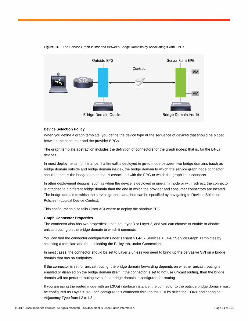
in Figure 31 shows that the service graph is not attached directly to bridge domains but through EPGs.
© 2017 Cisco and/or its affiliates. All rights reserved. This document is Cisco Public Information. Page 31 of 101
Figure 31. The Service Graph Is Inserted Between Bridge Domains by Associating It with EPGs
Device Selection Policy
When you define a graph template, you define the device type or the sequence of devices that should be placed
between the consumer and the provider EPGs.
The graph template abstraction includes the definition of connectors for the graph nodes: that is, for the L4-L7
devices.
In most deployments, for instance, if a firewall is deployed in go-to mode between two bridge domains (such as
bridge domain outside and bridge domain inside), the bridge domain to which the service graph node connector
should attach is the bridge domain that is associated with the EPG to which the graph itself connects.
In other deployment designs, such as when the device is deployed in one-arm mode or with redirect, the connector
is attached to a different bridge domain than the one in which the provider and consumer connectors are located.
The bridge domain to which the service graph is attached can be specified by navigating to Devices Selection
Policies > Logical Device Context.
This configuration also tells Cisco ACI where to deploy the shadow EPG.
Graph Connector Properties
The connector also has two properties: it can be Layer 3 or Layer 2, and you can choose to enable or disable
unicast routing on the bridge domain to which it connects.
You can find the connector configuration under Tenant > L4-L7 Services > L4-L7 Service Graph Templates by
selecting a template and then selecting the Policy tab, under Connections.
In most cases, the connector should be set to Layer 2 unless you need to bring up the pervasive SVI on a bridge
domain that has no endpoints.
If the connector is set for unicast routing, the bridge domain forwarding depends on whether unicast routing is
enabled or disabled on the bridge domain itself. If the connector is set to not use unicast routing, then the bridge
domain will not perform routing even if the bridge domain is configured for routing.
If you are using the routed mode with an L3Out interface instance, the connector to the outside bridge domain must
be configured as Layer 3. You can configure this connector through the GUI by selecting CON1 and changing
Adjacency Type from L2 to L3.

© 2017 Cisco and/or its affiliates. All rights reserved. This document is Cisco Public Information. Page 32 of 101
You can set the adjacency type through REST calls as follows:
<vnsAbsConnection name = "CON1" adjType=L3>
<vnsRsAbsConnectionConns tDn="uni/tn-Sales/AbsGraph-WebGraph/AbsTermNodeCon-
Consumer/AbsTConn" />
<vnsRsAbsConnectionConns tDn="uni/tn-Sales/AbsGraph-WebGraph/AbsNode-Virtual-
Server/AbsFConn-external" />
</vnsAbsConnection>
Deploying the Graph Template on Multiple EPG Pairs
The service graph is always associated with a contract between two EPGs.
A L4-L7 device can be connected through a service graph to multiple EPGs. Because the interfaces of the L4-L7
devices are the same, Cisco ACI allocates a different VLAN for the L4-L7 interface and the associated shadow
EPG each time the consumer-side or provider-side EPG is in a different bridge domain.
Figure 32 illustrates this point. In this figure, the graph template is applied one time between the EPG outside and
the EPG web interfaces, and it is applied a second time between the EPG outside and EPG appliance interfaces.
The EPG web and EPG appliance interfaces are in the same bridge domain; hence, the L4-L7 appliance interfaces
are associated with two shadow EPGs: one for BD1 and one for BD2.
Even if the graph template is applied to more EPGs in BD1 or BD2, the L4-L7 appliance is still connected only to
the two shadow EPGs.
Figure 32. When the Service Graph Is Used Between Multiple EPGs on Two Bridge Domains, the L4-L7 Appliance Always Is Attached to Two Shadow EPGs
If the graph template is applied to EPGs in different bridge domains, Cisco ACI will configure more shadow EPGs
(one per bridge domain), as shown in Figure 33. In this example, the L4-L7 appliance has the server-side NIC
configured to trunk multiple VLANs (VLAN 20 for the shadow EPG in BD2, and VLAN 30 for the shadow EPG in
BD3). With a L4-L7 deployment with a device package, Cisco ACI assigns the VLAN to the L4-L7 device interface
and to the shadow EPGs, making sure that they match.

© 2017 Cisco and/or its affiliates. All rights reserved. This document is Cisco Public Information. Page 33 of 101
Figure 33. When the Service Graph Is Used Between Multiple EPGs in Three Bridge Domains, the L4-L7 Appliance Is Attached to Three Shadow EPGs, and the NICs on the Appliance Trunk Multiple VLANs
You can also change the device selection policies (logical device contexts) to select a different NIC for each EPG
to which that the graph template is applied.
Assume that you had defined these logical interfaces:
<vnsLDevVip name="ASAv01-cluster">
<vnsCDev name="ASAv01-active" vmName="ASAv01" vcenterName="line1" >
<vnsCIf name="Gig0/0" vnicName="Network adapter 2"/>
<vnsCIf name="Gig0/1" vnicName="Network adapter 3"/>
<vnsCIf name="Gig0/2" vnicName="Network adapter 4"/>
</vnsCDev>
<vnsLIf name="external">
<vnsRsMetaIf tDn="uni/infra/mDev-CISCO-ASA-1.2/mIfLbl-external"/>
<vnsRsCIfAtt tDn="uni/tn-TenantName/lDevVip-ASAv01-cluster/cDev-ASAv01-
active/cIf-[Gig0/0]"/>
</vnsLIf>
<vnsLIf name="internal">
<vnsRsMetaIf tDn="uni/infra/mDev-CISCO-ASA-1.2/mIfLbl-internal"/>
<vnsRsCIfAtt tDn="uni/tn-TenantName/lDevVip-ASAv01-cluster/cDev-ASAv01-
active/cIf-[Gig0/1]"/>
</vnsLIf>
<vnsLIf name="internal2">
<vnsRsMetaIf tDn="uni/infra/mDev-CISCO-ASA-1.2/mIfLbl-internal"/>
<vnsRsCIfAtt tDn="uni/tn-TenantName/lDevVip-ASAv01-cluster/cDev-ASAv01-
active/cIf-[Gig0/2]"/>
</vnsLIf>
<vnsLIf name="internal3">
<vnsRsMetaIf tDn="uni/infra/mDev-CISCO-ASA-1.2/mIfLbl-internal"/>
<vnsRsCIfAtt tDn="uni/tn-TenantName/lDevVip-ASAv01-cluster/cDev-ASAv01-
active/cIf-[Gig0/3]"/>
</vnsLIf>

© 2017 Cisco and/or its affiliates. All rights reserved. This document is Cisco Public Information. Page 34 of 101
Assume that you defined three contracts as in the following XML script:
<vzBrCP name="c1">
<vzSubj name="http">
<vzRsSubjGraphAtt tnVnsAbsGraphName="g1"/>
</vzSubj>
</vzBrCP>
<vzBrCP name="c2">
<vzSubj name="http">
<vzRsSubjGraphAtt tnVnsAbsGraphName="g1"/>
</vzSubj>
</vzBrCP>
<vzBrCP name="c3">
<vzSubj name="http">
<vzRsSubjGraphAtt tnVnsAbsGraphName="g1"/>
</vzSubj>
You can then define a logical device selection policy like the one shown here that selects the same outside
interface for each contract (c1, c2, and c3), but a different inside interface for each contract:
<vnsLDevCtx ctrctNameOrLbl="c1" graphNameOrLbl="any" nodeNameOrLbl="any">
<vnsRsLDevCtxToLDev tDn="uni/tn-TenantName/lDevVip-ASAv01-cluster"/>
<vnsLIfCtx connNameOrLbl="external">
<vnsRsLIfCtxToLIf tDn="uni/tn-TenantName/lDevVip-ASAv01-cluster/lIf-
external"/>
<vnsRsLIfCtxToBD tDn="uni/tn-TenantName/BD-consBD1"/>
</vnsLIfCtx>
<vnsLIfCtx connNameOrLbl="internal">
<vnsRsLIfCtxToLIf tDn="uni/tn-TenantName/lDevVip-ASAv01-cluster/lIf-
internal"/>
<vnsRsLIfCtxToBD tDn="uni/tn-TenantName/BD-provBD1"/>
</vnsLIfCtx>
</vnsLDevCtx>
<vnsLDevCtx ctrctNameOrLbl="c2" graphNameOrLbl="any" nodeNameOrLbl="any">
<vnsRsLDevCtxToLDev tDn="uni/tn-TenantName/lDevVip-ASAv01-cluster"/>
<vnsLIfCtx connNameOrLbl="external">
<vnsRsLIfCtxToLIf tDn="uni/tn-TenantName/lDevVip-ASAv01-cluster/lIf-
external"/>
<vnsRsLIfCtxToBD tDn="uni/tn-TenantName/BD-consBD1"/>
</vnsLIfCtx>
<vnsLIfCtx connNameOrLbl="internal">
<vnsRsLIfCtxToLIf tDn="uni/tn-TenantName/lDevVip-ASAv01-cluster/lIf-
internal2"/>
<vnsRsLIfCtxToBD tDn="uni/tn-TenantName/BD-provBD2"/>
</vnsLIfCtx>
</vnsLDevCtx>
<vnsLDevCtx ctrctNameOrLbl="c3" graphNameOrLbl="any" nodeNameOrLbl="any">
<vnsRsLDevCtxToLDev tDn="uni/tn-TenantName/lDevVip-ASAv01-cluster"/>

© 2017 Cisco and/or its affiliates. All rights reserved. This document is Cisco Public Information. Page 35 of 101
<vnsLIfCtx connNameOrLbl="external">
<vnsRsLIfCtxToLIf tDn="uni/tn-TenantName/lDevVip-ASAv01-cluster/lIf-
external"/>
<vnsRsLIfCtxToBD tDn="uni/tn-TenantName/BD-consBD1"/>
</vnsLIfCtx>
<vnsLIfCtx connNameOrLbl="internal">
<vnsRsLIfCtxToLIf tDn="uni/tn-TenantName/lDevVip-ASAv01-cluster/lIf-
internal3"/>
<vnsRsLIfCtxToBD tDn="uni/tn-TenantName/BD-provBD3"/>
</vnsLIfCtx>
</vnsLDevCtx>
Deployment Modes
Cisco ACI supports these deployment modes for L4-L7 devices with the service graph:
● Go-to mode (also known as routed mode): In this mode, the default gateway for the servers is the L4-L7
device.
● Go-to mode with service graph redirect: In this mode, the default gateway for the servers is the Cisco ACI
bridge domain, and traffic is sent to the L4-L7 device based on the contract configuration between EPGs.
Service graph redirect is the preferred deployment mode for the service graph when Cisco Nexus 9300 EX
and FX platform switches are used.
● Go-through mode (also known as transparent mode or bridged mode): In this mode, the default gateway for
the servers is the client-side bridge domain, and the L4-L7 device bridges the client-side bridge domain and
the server-side bridge domain.
● One-arm mode: in this mode, the default gateway for the servers is the server-side bridge domain, and the
L4-L7 device is configured for source NAT (SNAT).
Routed Mode (Go-To Mode)
The simplest way to deploy a service graph in routed mode is to use NAT on the L4-L7 device. Cisco ACI also
supports service devices deployed in routed mode with either static or dynamic routing by connecting the L4L7
device to a L3Out as described in “Using L3Out for Routing to the L4-L7 Device”.
This design requires two bridge domains: one for the client-side, or outside, interface; and one for the server-side,
or inside, interface. The default gateway for the servers is the service appliance internal or server-side interface IP
address.
The routing from the outside (clients) to the service device to the inside (servers) can be provided by the fabric
itself (through a VRF instance) or by an external router.
This document divides the routed mode designs into these categories:
● Routed mode with outside Layer 2 bridge domain: In this design, the outside of the service graph connects
to a Layer 2 bridge domain. The routing to the service device is implemented with an external routing
device.
● Routed mode with L3Out and NAT: In this design, the service graph connects to the outside network
through routing provided by the Cisco ACI fabric. This design can be implemented if the service device
implements NAT, as in the case of a load balancer or in the case of a firewall that is translating the internal
IP addresses.
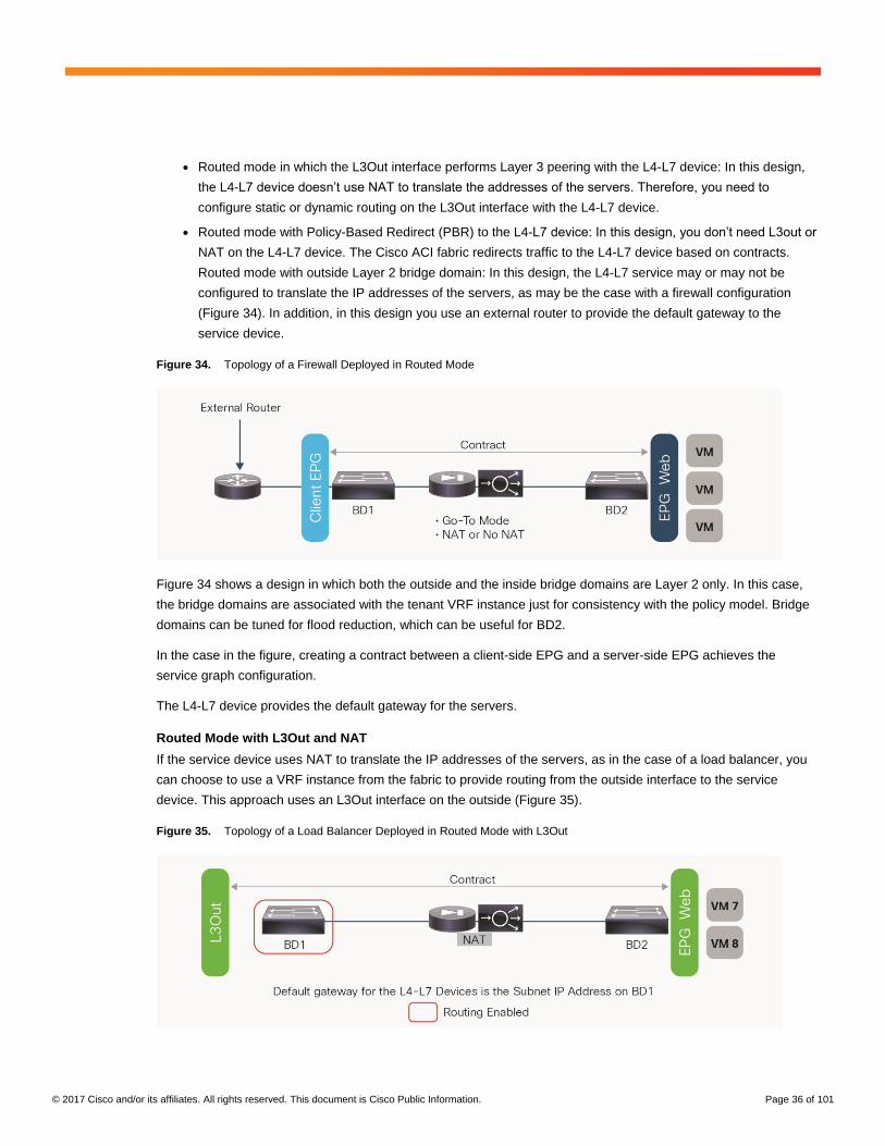
© 2017 Cisco and/or its affiliates. All rights reserved. This document is Cisco Public Information. Page 36 of 101
● Routed mode in which the L3Out interface performs Layer 3 peering with the L4-L7 device: In this design,
the L4-L7 device doesn’t use NAT to translate the addresses of the servers. Therefore, you need to
configure static or dynamic routing on the L3Out interface with the L4-L7 device.
● Routed mode with Policy-Based Redirect (PBR) to the L4-L7 device: In this design, you don’t need L3out or
NAT on the L4-L7 device. The Cisco ACI fabric redirects traffic to the L4-L7 device based on contracts.
Routed mode with outside Layer 2 bridge domain: In this design, the L4-L7 service may or may not be
configured to translate the IP addresses of the servers, as may be the case with a firewall configuration
(Figure 34). In addition, in this design you use an external router to provide the default gateway to the
service device.
Figure 34. Topology of a Firewall Deployed in Routed Mode
Figure 34 shows a design in which both the outside and the inside bridge domains are Layer 2 only. In this case,
the bridge domains are associated with the tenant VRF instance just for consistency with the policy model. Bridge
domains can be tuned for flood reduction, which can be useful for BD2.
In the case in the figure, creating a contract between a client-side EPG and a server-side EPG achieves the
service graph configuration.
The L4-L7 device provides the default gateway for the servers.
Routed Mode with L3Out and NAT
If the service device uses NAT to translate the IP addresses of the servers, as in the case of a load balancer, you
can choose to use a VRF instance from the fabric to provide routing from the outside interface to the service
device. This approach uses an L3Out interface on the outside (Figure 35).
Figure 35. Topology of a Load Balancer Deployed in Routed Mode with L3Out

© 2017 Cisco and/or its affiliates. All rights reserved. This document is Cisco Public Information. Page 37 of 101
Figure 35 shows a design in which the load balancer is placed between an L3Out instance and the servers. The
internal Bridge Domain (BD2) doesn’t offer any routing for the servers. The VRF instance of the tenant is
associated with the internal bridge domain just for consistency with the Cisco ACI object model. Because you need
to create a VRF (or private network) for a given tenant, you do not need to create another one explicitly for the
service graph; you can simply use the existing tenant VRF instance for the bridge domains used by the service
graph.
The L4-L7 device provides the default gateway for the servers.
The routing on the L4-L7 device uses static routes pointing to the subnet of the outside bridge domain.
The outside bridge domain in this figure offers routing for the service appliance. The subnet address of the outside
bridge domain is the default gateway of the service appliance. The VRF instance of the tenant is associated with
the outside bridge domain. The routing to the outside is implemented by configuring an L3Out instance.
Because BD1 has routing enabled, you need to make sure that BD1 learns only the NAT addresses of the virtual
machines by configuring Limit IP Learning to Subnet (which was previously called Subnet Check). You also need
to make sure that a maximum of 1024 IP addresses are learned on this interface (based on the verified scalability
limits for Cisco ACI Release 2.3), and that the IP addresses are aged independently by configuring IP Aging.
In the case of this design, the service graph configuration is achieved by creating a contract between the L3Out
EPG (L3InstP) and the server EPG.
Routed Mode with L3Out Routing to the L4-L7 Device
This design consists of two VRF instances: one to provide route peering with the outside of the Cisco ACI fabric
and to the outside or client-side interface of a firewall or a load balancer, and another for the server farm. Note that
you don’t need to use two bridge domains for this design; you can have only one for the servers.
The bridge domain doesn’t need to be configured for routing. The server default gateway then would be the L4-L7
device.
Figure 36 illustrates this design.
Figure 36. Topology of a Routed L4-L7 Deployment with Static or Dynamic Routing to the L4-L7 Device

© 2017 Cisco and/or its affiliates. All rights reserved. This document is Cisco Public Information. Page 38 of 101
The VRF outside instance has two L3Out interfaces: one configured for routing to the WAN, and one configured for
routing to the firewall. The contract for this service graph is established between the L3Out interface to the WAN
and the server EPG. The consumer connector of the service graph is configured to be associated with the L3Out
external network interface to the firewall.
The outside connector of the service graph must also be configured for adjacency type Layer 3 and for unicast
routing.
You can find the connector configuration under Tenant > L4-L7 Services > L4-L7 Service Graph Templates by
selecting a template and then selecting the Policy tab, under Connections.
In this design, you may want to tune BD2 to reduce flooding.
If the active-standby L4-L7 device pair is connected to first-generation leaf switches with vPC and static routing,
make sure that the active and standby devices both connect to the same leaf pairs. If instead they are connected to
Cisco Nexus 9300 EX or FX platform switches, make sure that you use Cisco ACI Release 2.3 or later and
configure Fabric > Access Policies > Global Policies > Fabric Wide Setting Policy in order to select the option
called Disable Remote EP Learn.
If the active-standby L4-L7 device pair is connected to a fabric that includes both first- and second-generation leaf
switches, and if servers are connected to the same leaf switches as the L4-L7 devices, you should configure one of
these options:
● You can configure VRF outside for egress filtering.
● Alternatively, if the fabric is running Cisco ACI Release 2.2(2e) or later, you should disable remote endpoint
learning for the border leaf switches by going to Fabric > Access Policies > Global Policies > Fabric Wide
Setting Policy and selecting Disable Remote EP Learn.
For more information, refer to the section "Using L3Out for Routing to the L4L7 Device."
Routed Mode with PBR to the L4-L7 Device
Another deployment model you can use is PBR. Unlike previous design options, PBR doesn’t require L3Out for the
service node, two VRF instances, or NAT. Using PBR, Cisco ACI fabric can route traffic to the service node based
on the source EPG, the destination EPG, and contract filter matching. The bridge domain needs to be configured
for routing. The server default gateway and service node (PBR node) gateway must be a Cisco ACI fabric bridge
domain subnet (Figure 37).

© 2017 Cisco and/or its affiliates. All rights reserved. This document is Cisco Public Information. Page 39 of 101
Figure 37. Topology of a Routed L4-L7 Deployment with PBR to the L4-L7 Device
The PBR node has two interfaces: one configured for the consumer side and one configured for the provider side.
Both PBR node connectors must be in a bridge domain and must not be in the consumer or provider bridge
domain. You thus need a service bridge domain, and the connectors must be configured for unicast routing. This
service bridge domain requirement will be removed in Cisco ACI Release 3.1.
PBR requires a service graph, and the PBR node must be in go-to mode. PBR can be used in a one-arm mode
deployment as well (Figure 38).
Note: For one-arm deployments make sure that your firewall allows traffic to be routed in and out the same
security zone interface.
Figure 38. Topology of a Routed L4-L7 Deployment with PBR One-Arm Mode
PBR also can be used in a two-VRF-instance design with route leaking. You can place a PBR device between
consumer and provider VRF instances or in either of them, as in Figure 39.

© 2017 Cisco and/or its affiliates. All rights reserved. This document is Cisco Public Information. Page 40 of 101
Figure 39. Topology of a Routed L4-L7 Deployment with PBR in Two VRF Instances
For more information about PBR, see the Layer 4 to Layer 7 services deployment guide at
https://www.cisco.com/c/en/us/td/docs/switches/datacenter/aci/apic/sw/1-x/L4-
L7_Services_Deployment/guide/b_L4L7_Deploy_ver211.html.
Transparent Mode (Go-Through Mode)
The design requires two bridge domains. In transparent mode, the L4-L7 device is deployed in pass-through
(go-through) mode. The service device doesn’t provide the default gateway for the servers. The servers’ default
gateway is either the subnet on the outside bridge domain or an external router. The routing from the outside
(clients) to the inside (servers) interfaces can be provided by the fabric itself (through a VRF instance) or by an
external router.
With go-through mode, Cisco ACI doesn’t let you configure IP routing on both bridge domains, and even if you
configure hardware proxy, Cisco ACI will set the bridge domain for unknown unicast flooding and ARP flooding.

© 2017 Cisco and/or its affiliates. All rights reserved. This document is Cisco Public Information. Page 41 of 101
This document divides the transparent mode designs into two categories:
● Transparent mode with outside Layer 2 bridge domain: In this design, the outside of the service graph
connects to a Layer 2 bridge domain. The routing to the service device is implemented with an external
routing device.
● Transparent mode with L3Out: In this design, the service graph connects to the outside network through
routing provided by the Cisco ACI fabric.
Transparent Mode with Outside Layer 2 Bridge Domain
Figure 40 shows a transparent mode deployment with routing provided by an external router.
The design requires two bridge domains. The default gateway for the servers is the IP address of the external
router. Tuning the bridge domains for flooding reduction is not possible because the service graph ensures that
Layer 2 unknown unicast flooding is enabled.
Figure 40. Firewall Deployed in Transparent Mode with Routing Outside the Fabric
Figure 41 shows a transparent mode deployment with routing provided by the Cisco ACI fabric.
This design requires two bridge domains. The default gateway for the servers is the IP address of the subnet of the
outside bridge domain. Because IP routing is enabled on BD1, the IP addresses of the endpoints in BD2 are
learned as if they were in BD1, and they are associated with the MAC address of the L4-L7 device.
Because BD1 has routing enabled, you need to make sure that BD1 learns only the addresses of the subnet that
you defined. Thus, you should configure Limit IP Learning to Subnet (which was previously called Subnet Check).
You also need to make sure that a maximum of 1024 IP addresses are learned on this interface (based on the
verified scalability limits for Cisco ACI Release 2.3), and that the IP addresses are aged independently by
configuring IP Aging.

© 2017 Cisco and/or its affiliates. All rights reserved. This document is Cisco Public Information. Page 42 of 101
Figure 41. Firewall Deployed in Transparent Mode with Routing Provided by the Cisco ACI Fabric
One-Arm Mode
Figure 42 shows a one-arm mode deployment with the classic networking constructs. Figure 43 shows the same
topology in Cisco ACI.
In one-arm mode, the default gateway for the servers is the router upstream. The load balancer is connected with
one VLAN to the router as well, which is the default gateway for the load balancer itself. The load balancer uses
source NAT for the traffic from the clients to the servers to help ensure receipt of the return traffic.
The default gateway for the servers is the subnet on BD2. The default gateway for the load balancer is the subnet
on BD3.
The contract is established between the external EPG and the server EPG, and it is associated with the service
graph.
This topology has three bridge domains: one bridge domain for the outside, or client side (BD1); one bridge domain
for the inside, or server side (BD2); and one bridge domain for connectivity with the load balancer (BD3). The VRF
instance is associated with all three bridge domains. With this setup, you can optimize flooding on BD2.
On BD3 the load balancer forwards traffic from the clients to the servers by routing it through the Cisco ACI fabric.
Therefore, you need to make sure that the only addresses learned in BD3 are the ones that belong to the BD3
subnet: that is, the virtual addresses announced by the load balancer and the NAT addresses.
You should configure Limit IP Learning to Subnet (which was previously called Subnet Check) on BD3. You also
need to make sure that a maximum of 1024 IP addresses are learned on this interface (based on the verified
scalability limits for Cisco ACI Release 2.3), and that the IP addresses are aged independently by configuring IP
Aging.

© 2017 Cisco and/or its affiliates. All rights reserved. This document is Cisco Public Information. Page 43 of 101
Figure 42. Deployment of a Load Balancer in One-Arm Mode
Figure 43. Load Balancer Deployed in One-Arm Mode in Cisco ACI
Physical Topology Choices
Typically, a service device carries three types of traffic:
● Management traffic between the APIC and the service node
● Data traffic
● Failover traffic between service nodes (if service-node high availability is needed)
This section describes the topology choices for this traffic (Figure 44).

© 2017 Cisco and/or its affiliates. All rights reserved. This document is Cisco Public Information. Page 44 of 101
Figure 44. Physical Topology
Management Traffic
To push policy from the APIC to the service node, management connectivity between the nodes is needed. Cisco
ACI fabric supports out-of-band management and in-band management, and both options are supported in an L4-
L7 device configuration (Figure 45):
● Out-of-band management: Use the APIC out-of-band management interface for communication with service
nodes. In this case, the management network is placed outside the Cisco ACI fabric.
● In-band management: Use the APIC in-band management interface for communication with service nodes.
In this case, the management network is placed within the Cisco ACI fabric.
Figure 45. Management Network

© 2017 Cisco and/or its affiliates. All rights reserved. This document is Cisco Public Information. Page 45 of 101
By default, out-of-band management is selected. If you select in-band management, you need to create an EPG for
the service node management interface and select it in the L4-L7 device configuration (Figure 46).
Figure 46. L4-L7 Device Configuration
Note: If the APIC has both out-of-band and in-band management IP addresses, the default route using in-band
management is preferred. If the APIC has both addresses and you want to use out-of-band management for
communication with the L4-L7 device, you need to make sure that the L4-L7 management IP address and the
APIC out-of-band management IP address are in the same subnet.
Data Traffic
To set up end-to-end connectivity between EPGs through the service node, you need to create data path networks
for service nodes. This process is performed automatically during service graph rendering. This section describes
domain and VLAN pool configuration for data traffic on both physical and virtual service devices.
Physical Appliances (Managed Mode)
For the physical domain in managed mode, use dynamic allocation mode for the VLAN range for the L4-L7 device
(Figure 47). The APIC will select VLANs from the VLAN range, configure the Cisco ACI fabric, and configure the
service device with the VLANs accordingly during service graph rendering.
The physical domain can contain a VLAN range set with static allocation mode, but the VLAN range specified with
dynamic allocation mode will be used for service graph deployment.
For L3Out route peering, the APIC will select the VLAN in the L3Out logical interface profile configuration.

© 2017 Cisco and/or its affiliates. All rights reserved. This document is Cisco Public Information. Page 46 of 101
Figure 47. Physical Appliance Configuration (Managed Mode)
Physical Appliances (Unmanaged Mode)
In unmanaged mode, specify the physical domain with the static allocation mode for the VLAN range for the L4-L7
device.
Specify the path and VLAN ID in the cluster interface, which are similar to the specifications for static path bindings
for the EPG (Figure 48).
Figure 48. Physical Appliance Configuration (Unmanaged Mode)
Virtual Appliances (Managed Mode and Unmanaged Mode)
For virtual appliances in both managed and unmanaged modes, specify the Virtual Machine Manager (VMM)
domain using the dynamic allocation mode for the VLAN range for the L4-L7 device (Figure 49). The APIC will
select VLANs from the VLAN range, configure the Cisco ACI fabric, create port groups for the service node
connector, and change the vNIC configuration of the virtual appliance during service graph rendering.

© 2017 Cisco and/or its affiliates. All rights reserved. This document is Cisco Public Information. Page 47 of 101
The VMM domain can also contain a VLAN range that uses static allocation mode, but the VLAN range specified
with dynamic allocation mode will be used for service graph deployment.
For L3Out route peering, the APIC selects the VLAN that is used in the L3Out logical interface profile configuration.
Figure 49. Virtual Appliance Configuration
Note: As of this writing, automatic vNIC placement is supported for the virtual appliance running in the VMware
VMM domain only. Trunk port groups are not supported. You thus need to create a different vNIC on the virtual
appliance for each connector for different cluster interfaces (a shadow EPG).
Failover Traffic
Each service device vendor has different failover link options and mechanisms (Figure 50). Typical options are
listed here:
● Dedicated physical interface for failover traffic (for example, F5 devices): The service device has a
dedicated physical interface for failover traffic only.
● Created failover VLAN and interface (for example, Cisco ASA devices): The service device doesn’t have a
dedicated physical interface. You need to create a failover VLAN or choose interfaces for failover traffic,
which typically are created on different physical interfaces, with one for data traffic.
● Shared (not dedicated) VLAN and logical interface (for example, Citrix devices): Failover traffic is
exchanged over the same VLAN as data traffic.
Typically, use of a dedicated physical interface and a directly cabled pair of failover devices is recommended. If
failover interfaces are connected to each service device directly, Cisco ACI fabric doesn’t have to manage the
failover network. If you prefer to in-band failover traffic within Cisco ACI fabric, you need to create an EPG for
failover traffic.

© 2017 Cisco and/or its affiliates. All rights reserved. This document is Cisco Public Information. Page 48 of 101
Figure 50. Failover Network Design Option
High-Availability Design and Configuration
This section describes high-availability design and configuration for both physical and virtual appliances: in
particular, ASA appliances. ASA appliances don’t have dedicated physical interfaces for failover traffic, so you
need to create failover interfaces: a failover link and a stateful failover link. These interfaces are for failover
communication only and are commonly used as individual interfaces.
For detailed information about ASA failover, please see document at
https://www.cisco.com/c/en/us/td/docs/security/asa/asa95/configuration/general/asa-95-general-config/ha-
failover.html.
If failover traffic is within the Cisco ACI fabric (in band), you need to configure an EPG for failover traffic. If the
service device is a virtual appliance, you also need to configure vNICs for the virtual appliance, because the APIC
doesn’t do this automatically.
High-Availability Connectivity from the Physical Appliance to the Fabric
ASA doesn’t allow user data traffic and failover traffic to share interfaces, even with different subinterfaces. You
must use a separate dedicated interface for the failover link. On the Cisco ACI fabric, you need to create an EPG
with static bindings for failover traffic. You can use different EPGs for the failover link and the stateful failover link
(Figure 51).

© 2017 Cisco and/or its affiliates. All rights reserved. This document is Cisco Public Information. Page 49 of 101
Figure 51. Physical Appliance Connectivity
High-Availability Connectivity from the Virtual Appliance to the Fabric
You need to create an EPG for the VMM domain for failover traffic (Figure 52), which create port-groups for the
EPG. Then you need to configure vNICs for the virtual appliance. You can use an EPG with static bindings if you
don’t want to use the VMware VMM domain. In this case, you manually create a port group for failover traffic and
configure static bindings for the EPG.
Figure 52. Virtual Appliance Connectivity
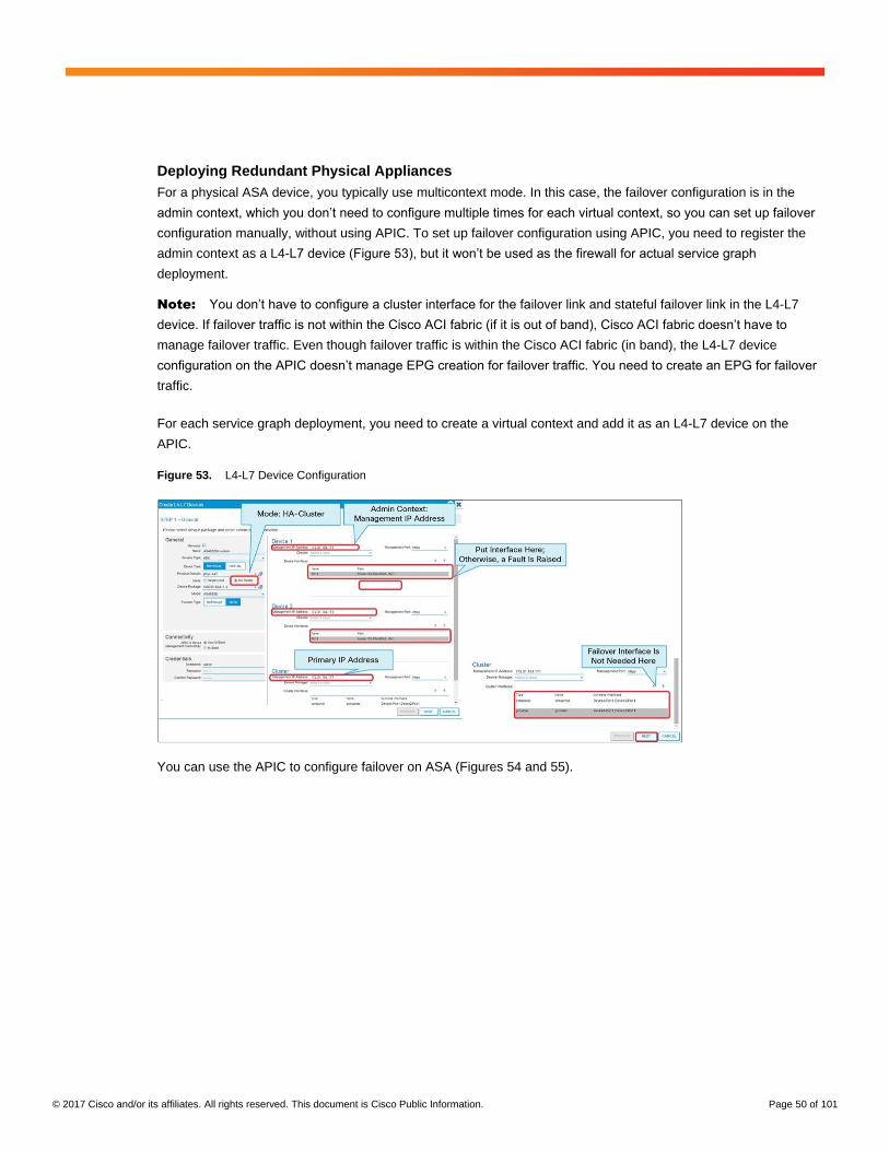
© 2017 Cisco and/or its affiliates. All rights reserved. This document is Cisco Public Information. Page 50 of 101
Deploying Redundant Physical Appliances
For a physical ASA device, you typically use multicontext mode. In this case, the failover configuration is in the
admin context, which you don’t need to configure multiple times for each virtual context, so you can set up failover
configuration manually, without using APIC. To set up failover configuration using APIC, you need to register the
admin context as a L4-L7 device (Figure 53), but it won’t be used as the firewall for actual service graph
deployment.
Note: You don’t have to configure a cluster interface for the failover link and stateful failover link in the L4-L7
device. If failover traffic is not within the Cisco ACI fabric (if it is out of band), Cisco ACI fabric doesn’t have to
manage failover traffic. Even though failover traffic is within the Cisco ACI fabric (in band), the L4-L7 device
configuration on the APIC doesn’t manage EPG creation for failover traffic. You need to create an EPG for failover
traffic.
For each service graph deployment, you need to create a virtual context and add it as an L4-L7 device on the
APIC.
Figure 53. L4-L7 Device Configuration
You can use the APIC to configure failover on ASA (Figures 54 and 55).

© 2017 Cisco and/or its affiliates. All rights reserved. This document is Cisco Public Information. Page 51 of 101
Figure 54. Stateful Failover Link Configuration
Figure 55. Failover Link Configuration
You also must configure a secondary management IP address. Otherwise, the APIC can’t access the secondary
ASA (Figure 56).

© 2017 Cisco and/or its affiliates. All rights reserved. This document is Cisco Public Information. Page 52 of 101
Figure 56. Secondary Management IP Address Configuration
You can also configure a port channel (Figure 57). This configuration is optional.
Figure 57. Port-Channel Configuration
When you successfully complete the configuration, you can see failover configuration on both ASA devices.
Primary Cisco ASA Configuration (Performed by Cisco APIC)
interface GigabitEthernet0/0
channel-group 11 mode active
!

© 2017 Cisco and/or its affiliates. All rights reserved. This document is Cisco Public Information. Page 53 of 101
interface GigabitEthernet0/1
channel-group 11 mode active
interface GigabitEthernet0/6
description LAN Failover Interface
!
interface GigabitEthernet0/7
description STATE Failover Interface
!
failover
failover lan unit primary
failover lan interface failover-lan GigabitEthernet0/6
failover polltime unit 3 holdtime 9
failover link failover-link GigabitEthernet0/7
failover interface ip failover-lan 10.1.2.1 255.255.255.0 standby 10.1.2.2
failover interface ip failover-link 10.1.1.1 255.255.255.0 standby 10.1.1.2
interface Management0/0
management-only
nameif management
security-level 100
ip address 172.31.184.171 255.255.252.0 standby 172.31.184.172
Secondary Cisco ASA Configuration (Performed by Cisco APIC)
interface GigabitEthernet0/0
channel-group 11 mode active
!
interface GigabitEthernet0/1
channel-group 11 mode active
interface GigabitEthernet0/6
description LAN Failover Interface
!
interface GigabitEthernet0/7
description STATE Failover Interface
!
failover
failover lan unit secondary
failover lan interface failover-lan GigabitEthernet0/6
failover polltime unit 3 holdtime 9
failover link failover-link GigabitEthernet0/7
failover interface ip failover-lan 10.1.2.1 255.255.255.0 standby 10.1.2.2
failover interface ip failover-link 10.1.1.1 255.255.255.0 standby 10.1.1.2

© 2017 Cisco and/or its affiliates. All rights reserved. This document is Cisco Public Information. Page 54 of 101
interface Management0/0
management-only
nameif management
security-level 100
ip address 172.31.184.171 255.255.252.0 standby 172.31.184.172
Failover Status (Primary)
ASA5525X-1# show failover
Failover On
Failover unit Primary
Failover LAN Interface: failover-lan GigabitEthernet0/6 (up)
Reconnect timeout 0:00:00
Unit Poll frequency 3 seconds, holdtime 9 seconds
Interface Poll frequency 5 seconds, holdtime 25 seconds
Interface Policy 1
Monitored Interfaces 1 of 216 maximum
MAC Address Move Notification Interval not set
Version: Ours 9.5(2), Mate 9.5(2)
Last Failover at: 14:37:06 UTC Feb 5 2016
This host: Primary - Active
Active time: 8781 (sec)
slot 0: ASA5525 hw/sw rev (1.0/9.5(2)) status (Up Sys)
admin Interface management (172.31.184.171): Normal (Monitored)
slot 1: SFR5525 hw/sw rev (N/A/5.3.1-152) status (Up/Up)
ASA FirePOWER, 5.3.1-152, Up, (Monitored)
Other host: Secondary - Standby Ready
Active time: 0 (sec)
slot 0: ASA5525 hw/sw rev (1.0/9.5(2)) status (Up Sys)
admin Interface management (172.31.184.172): Normal (Monitored)
slot 1: SFR5525 hw/sw rev (N/A/5.3.1-152) status (Up/Up)
ASA FirePOWER, 5.3.1-152, Up, (Monitored)
<snip>
Failover Status (Secondary)
ASA5525X-1(config)# show failover
Failover On
Failover unit Secondary
Failover LAN Interface: failover-lan GigabitEthernet0/6 (up)
Reconnect timeout 0:00:00
Unit Poll frequency 3 seconds, holdtime 9 seconds
Interface Poll frequency 5 seconds, holdtime 25 seconds
Interface Policy 1
Monitored Interfaces 1 of 216 maximum
MAC Address Move Notification Interval not set

© 2017 Cisco and/or its affiliates. All rights reserved. This document is Cisco Public Information. Page 55 of 101
Version: Ours 9.5(2), Mate 9.5(2)
Last Failover at: 14:16:36 UTC Feb 5 2016
This host: Secondary - Standby Ready
Active time: 0 (sec)
slot 0: ASA5525 hw/sw rev (1.0/9.5(2)) status (Up Sys)
admin Interface management (172.31.184.172): Normal (Monitored)
slot 1: SFR5525 hw/sw rev (N/A/5.3.1-152) status (Up/Up)
ASA FirePOWER, 5.3.1-152, Up, (Monitored)
Other host: Primary - Active
Active time: 8700 (sec)
slot 0: ASA5525 hw/sw rev (1.0/9.5(2)) status (Up Sys)
admin Interface management (172.31.184.171): Normal (Monitored)
slot 1: SFR5525 hw/sw rev (N/A/5.3.1-152) status (Up/Up)
ASA FirePOWER, 5.3.1-152, Up, (Monitored)
<snip>
Deploying Redundant Virtual Appliances
Regardless of whether you are using in-band or out-of-band failover traffic, you need to create a port group for
failover traffic and attach the vNIC to the port group. The device interface and cluster interface for failover traffic
should be configured in the L4-L7 device (Figures 58 and 59).
Figure 58. L4-L7 Device Configuration
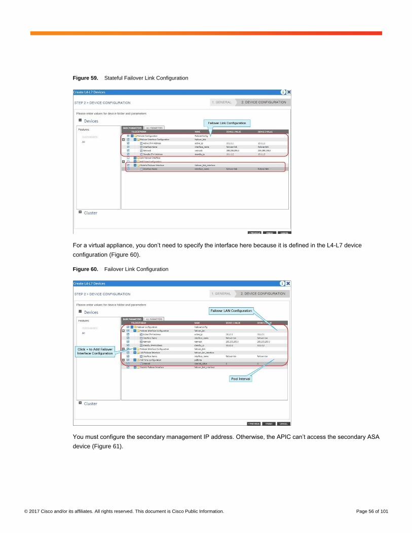
© 2017 Cisco and/or its affiliates. All rights reserved. This document is Cisco Public Information. Page 56 of 101
Figure 59. Stateful Failover Link Configuration
For a virtual appliance, you don’t need to specify the interface here because it is defined in the L4-L7 device
configuration (Figure 60).
Figure 60. Failover Link Configuration
You must configure the secondary management IP address. Otherwise, the APIC can’t access the secondary ASA
device (Figure 61).

© 2017 Cisco and/or its affiliates. All rights reserved. This document is Cisco Public Information. Page 57 of 101
Figure 61. Secondary Management IP Address Configuration
After you’ve completed the configuration successfully, you can see the failover configuration on both Cisco
Adaptive Security Virtual Appliance (ASAv) devices.
Primary Cisco ASA Configuration (Performed by Cisco APIC)
interface GigabitEthernet0/2
description LAN Failover Interface
!
interface GigabitEthernet0/3
description STATE Failover Interface
!
interface Management0/0
management-only
nameif management
security-level 0
ip address 172.31.184.223 255.255.252.0 standby 172.31.184.224
failover
failover lan unit primary
failover lan interface failover-lan GigabitEthernet0/2
failover polltime unit 3 holdtime 9
failover link failover-link GigabitEthernet0/3

© 2017 Cisco and/or its affiliates. All rights reserved. This document is Cisco Public Information. Page 58 of 101
failover interface ip failover-lan 10.1.2.1 255.255.255.0 standby 10.1.2.2
failover interface ip failover-link 10.1.1.1 255.255.255.0 standby 10.1.1.2
Secondary Cisco ASA Configuration (Performed by Cisco APIC)
interface GigabitEthernet0/2
description LAN Failover Interface
!
interface GigabitEthernet0/3
description STATE Failover Interface
!
interface Management0/0
management-only
nameif management
security-level 0
ip address 172.31.184.223 255.255.252.0 standby 172.31.184.224
failover
failover lan unit secondary
failover lan interface failover-lan GigabitEthernet0/2
failover polltime unit 3 holdtime 9
failover link failover-link GigabitEthernet0/3
failover interface ip failover-lan 10.1.2.1 255.255.255.0 standby 10.1.2.2
failover interface ip failover-link 10.1.1.1 255.255.255.0 standby 10.1.1.2
Deploying Clustering for Physical Appliances (Cisco ASA Cluster)
Cisco ASA clustering allows you to group multiple ASA nodes together as a single logical device to provide high
availability and scalability. ASA clustering also can be integrated with Cisco ACI. ASA clustering has two modes:
spanned EtherChannel mode (recommended) and individual interface mode. This document focuses on the
spanned EtherChannel mode because it is the recommended choice.
One member of the cluster is elected as the master switch. The master switch handles the configuration, which is
replicated on the slave switches. In spanned EtherChannel mode, all ASA devices in the cluster use the same port
channel, and traffic is load-balanced as part of the port-channel operation. From the perspective of the Cisco ACI
fabric, the cluster is a single logical device connected to the Cisco ACI fabric through one port channel (Figure 62).

© 2017 Cisco and/or its affiliates. All rights reserved. This document is Cisco Public Information. Page 59 of 101
Figure 62. Cisco ASA Clustering
For more information about ASA clustering, see the Cisco ASA cluster section in the Cisco ASA configuration
guide at https://www.cisco.com/c/en/us/td/docs/security/asa/asa97/configuration/general/asa-97-general-config/ha-
cluster.html.
Note: As of this writing, for spanned EtherChannel mode, ASA devices in the same ASA cluster must be
connected to the Cisco ACI fabric through the same vPC or port channel. The reason for this requirement is that
Cisco ACI fabric will learn the same endpoint from different port-channel interfaces, which may cause endpoint
flapping if you use different port channels. Thus, ASA clustering across pods is not supported. The Cisco ACI fabric
capabilities will be enhanced handle this situation in Q2CY18.
For L4-L7 device configuration, note that Cisco ASA clustering is supported on physical ASA devices only, not
virtual ASA devices. As in the physical appliance example in the previous section, you need to create a virtual
context and add it as an L4-L7 device on the APIC. However, you need to use the Single Node mode, because
from the perspective of Cisco ACI, the cluster is one big logical device. The APIC needs to communicate with the
master switch to push the configuration to the ASA devices in the cluster.
In a L4-L7 device configuration, the device management address is the master management IP address in the
virtual context. The cluster management IP address is the master management IP address in the administration
context (Figures 63 and 64).

© 2017 Cisco and/or its affiliates. All rights reserved. This document is Cisco Public Information. Page 60 of 101
Figure 63. L4-L7 Device Configuration
Figure 64. L4-L7 Device Configuration (Optional)
Note that ASA clustering must be configured beforehand. Clustering configuration is not supported during L4-L7
device creation on the APIC using a device package. To set up ASA clustering, you need separate port channels
for the cluster control plane in addition to the spanned EtherChannel for cluster data plane (Figure 65).
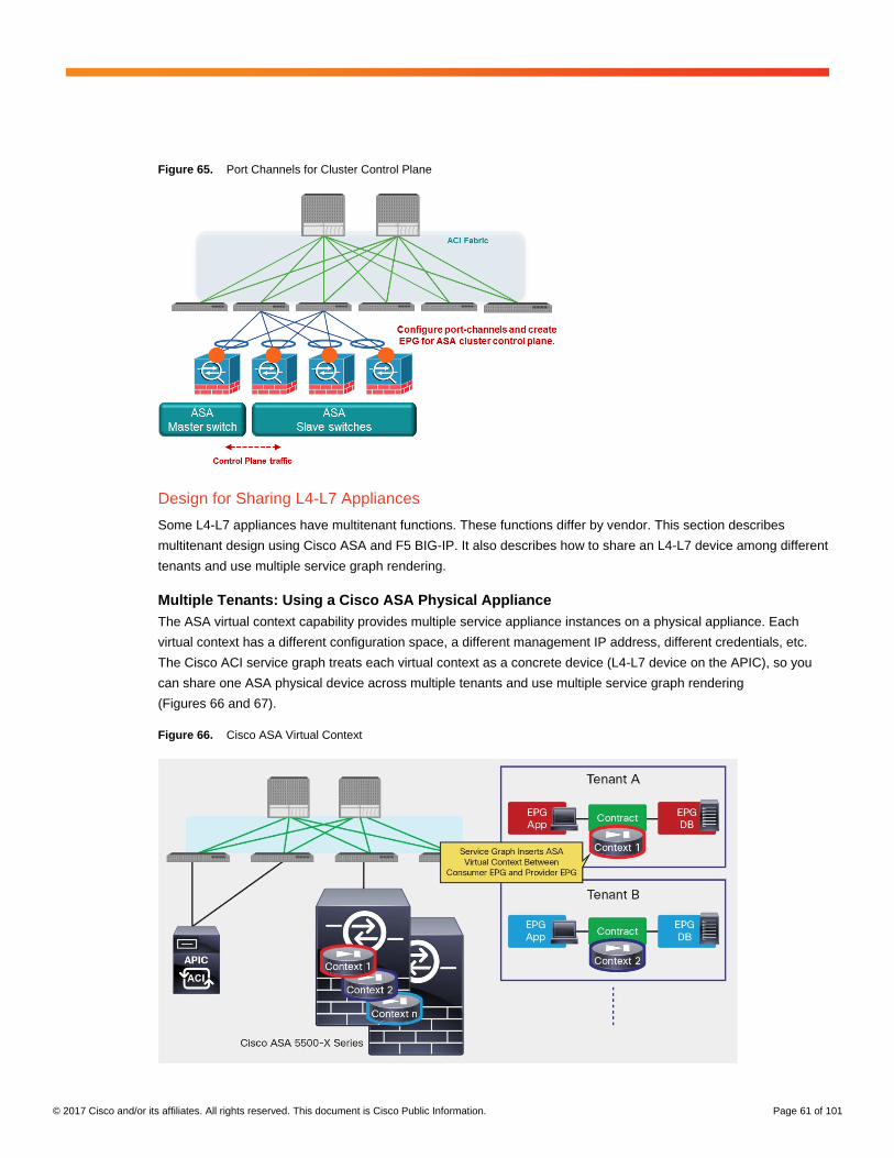
© 2017 Cisco and/or its affiliates. All rights reserved. This document is Cisco Public Information. Page 61 of 101
Figure 65. Port Channels for Cluster Control Plane
Design for Sharing L4-L7 Appliances
Some L4-L7 appliances have multitenant functions. These functions differ by vendor. This section describes
multitenant design using Cisco ASA and F5 BIG-IP. It also describes how to share an L4-L7 device among different
tenants and use multiple service graph rendering.
Multiple Tenants: Using a Cisco ASA Physical Appliance
The ASA virtual context capability provides multiple service appliance instances on a physical appliance. Each
virtual context has a different configuration space, a different management IP address, different credentials, etc.
The Cisco ACI service graph treats each virtual context as a concrete device (L4-L7 device on the APIC), so you
can share one ASA physical device across multiple tenants and use multiple service graph rendering
(Figures 66 and 67).
Figure 66. Cisco ASA Virtual Context

© 2017 Cisco and/or its affiliates. All rights reserved. This document is Cisco Public Information. Page 62 of 101
Figure 67. L4-L7 Device Configuration on Cisco APIC
The cluster IP address should be the ASA admin context IP address, so the APIC can allocate the interface in the
system context and configure it in the virtual context during service graph rendering.
Note: As of this writing, the APIC doesn’t manage ASA virtual context creation, so you need to create the virtual
context beforehand.
Multiple Tenants: Using an F5 BIG-IP Physical Appliance
F5 BIG-IP Local Traffic Manager (LTM) has a route domain capability similar to VRF. It provides routing table
isolation, but all partitions are in the same service device and share the same management IP address, which is
different from the ASA multi-context capability. The Cisco ACI service graph treats a BIG-IP LTM physical
appliance, which hosts multiple partitions, as one concrete device. It can be exported to multiple tenants and can
be used in multiple service graph rendering. During service graph rendering, the APIC creates new partitions
automatically, so you don’t have to create partitions and add concrete devices beforehand (Figure 68).
Note: Some BIG-IP LTM platforms support virtual clustered multiprocessing (vCMP), which is similar to the ASA
virtual context. vCMP allows you to run multiple instances of the BIG-IP software on a single hardware platform.
For details, please see the F5 documentation.
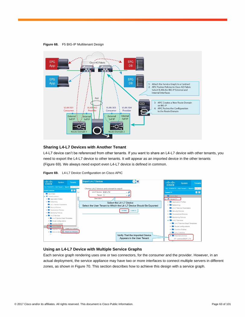
© 2017 Cisco and/or its affiliates. All rights reserved. This document is Cisco Public Information. Page 63 of 101
Figure 68. F5 BIG-IP Multitenant Design
Sharing L4-L7 Devices with Another Tenant
L4-L7 device can’t be referenced from other tenants. If you want to share an L4-L7 device with other tenants, you
need to export the L4-L7 device to other tenants. It will appear as an imported device in the other tenants
(Figure 69). We always need export even L4-L7 device is defined in common.
Figure 69. L4-L7 Device Configuration on Cisco APIC
Using an L4-L7 Device with Multiple Service Graphs
Each service graph rendering uses one or two connectors, for the consumer and the provider. However, in an
actual deployment, the service appliance may have two or more interfaces to connect multiple servers in different
zones, as shown in Figure 70. This section describes how to achieve this design with a service graph.

© 2017 Cisco and/or its affiliates. All rights reserved. This document is Cisco Public Information. Page 64 of 101
Figure 70. Using an L4-L7 Device with Multiple Service Graphs
The main point is that you can create multiple cluster interfaces on a concrete device and then specify which
cluster interface defined in the L4-L7 device will be used for the connector in the device selection policy. This
cluster interface can be shared by using multiple service graph rendering.
Example 1: Share Consumer Interface (Virtual Appliance)
The example in Figure 70 has three EPGs, two service graphs, and one concrete virtual service device. You create
three cluster interfaces in the L4-L7 device (Figure 71).
Figure 71. Cluster Interface (Virtual Appliance)
In the device selection policy, you specify which cluster interface defined in the L4-L7 device will be used for the
connector. This cluster interface can be shared by multiple service graph rendering (Figures 72 and 73). In this
example, cluster interface “external” is used twice:
● Service-Graph1 uses cluster interface “external” as the consumer connector and “internal1” as the provider
connector.

© 2017 Cisco and/or its affiliates. All rights reserved. This document is Cisco Public Information. Page 65 of 101
● Service-Graph2 uses cluster interface “external” as the consumer connector and “internal2” as the provider
connector.
Figure 72. Device Selection Policy for Service-Graph1 (Virtual Appliance)
Figure 73. Device Selection Policy for Service-Graph2 (Virtual Appliance)
Note: As of this writing, the VMware port group created by the APIC doesn’t support trunk mode, so if the bridge
domain of the connector is different for each service graph rendering, you need to a separate interface on the
virtual appliance.

© 2017 Cisco and/or its affiliates. All rights reserved. This document is Cisco Public Information. Page 66 of 101
Example 2: DMZ (Virtual Appliance)
The example in Figure 74 has three EPGs, two service graphs, and one concrete virtual service device. You create three cluster interfaces in the L4-L7 device.
Figure 74. Cluster Interface (Virtual Appliance)
The ASA DMZ interface (192.168.2.1) is the consumer and also the provider, so you use the “consumer and
provider” options for the cluster interface (Figure 75).
Figure 75. Configuring the Options for the Cluster Interface
In this example, the cluster interface “DMZ” is used twice (Figures 76 and 77):
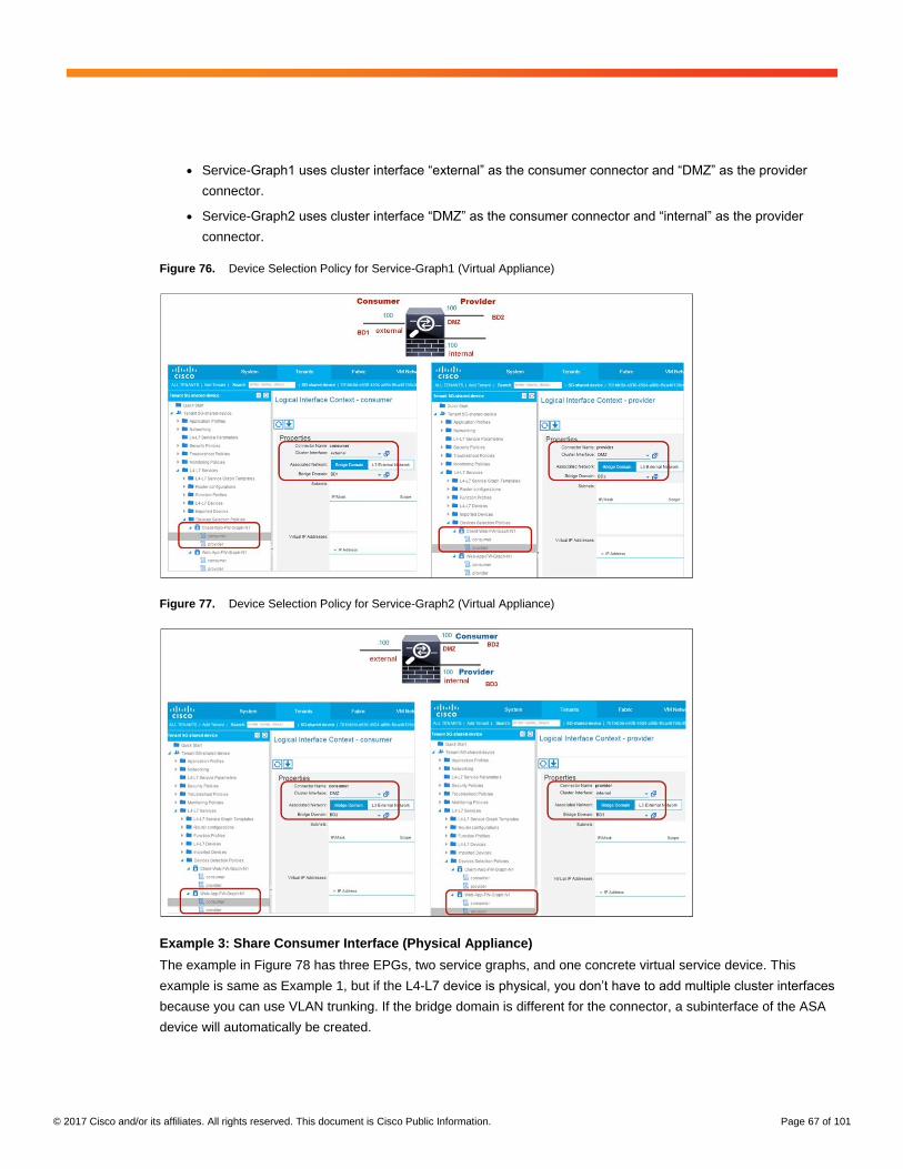
© 2017 Cisco and/or its affiliates. All rights reserved. This document is Cisco Public Information. Page 67 of 101
● Service-Graph1 uses cluster interface “external” as the consumer connector and “DMZ” as the provider
connector.
● Service-Graph2 uses cluster interface “DMZ” as the consumer connector and “internal” as the provider
connector.
Figure 76. Device Selection Policy for Service-Graph1 (Virtual Appliance)
Figure 77. Device Selection Policy for Service-Graph2 (Virtual Appliance)
Example 3: Share Consumer Interface (Physical Appliance)
The example in Figure 78 has three EPGs, two service graphs, and one concrete virtual service device. This
example is same as Example 1, but if the L4-L7 device is physical, you don’t have to add multiple cluster interfaces
because you can use VLAN trunking. If the bridge domain is different for the connector, a subinterface of the ASA
device will automatically be created.

© 2017 Cisco and/or its affiliates. All rights reserved. This document is Cisco Public Information. Page 68 of 101
Figure 78. Cluster Interface (Physical Appliance)
In this example, you use the same cluster interface for both service graphs, but the Bridge Domain (BD) for the
provider side is different, so a different subinterface is created on the service device (Figures 79 and 80):
● Service-Graph1 uses cluster interface “consumer” as the consumer connector and “provider” as the
provider connector. The provider side is BD2.
● Service-Graph2 uses cluster interface “external” as the consumer connector and “internal” as the provider
connector. The provider side is BD3.
Figure 79. Device Selection Policy for Service-Graph1 (Physical Appliance)
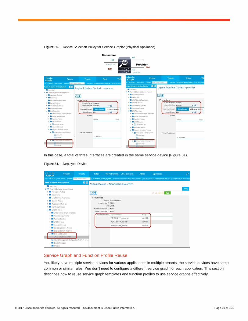
© 2017 Cisco and/or its affiliates. All rights reserved. This document is Cisco Public Information. Page 69 of 101
Figure 80. Device Selection Policy for Service-Graph2 (Physical Appliance)
In this case, a total of three interfaces are created in the same service device (Figure 81).
Figure 81. Deployed Device
Service Graph and Function Profile Reuse
You likely have multiple service devices for various applications in multiple tenants, the service devices have some
common or similar rules. You don’t need to configure a different service graph for each application. This section
describes how to reuse service graph templates and function profiles to use service graphs effectively.

© 2017 Cisco and/or its affiliates. All rights reserved. This document is Cisco Public Information. Page 70 of 101
Service Graph Template Reuse
Service graph templates can be applied to multiple contracts (Figure 82). If multiple service devices have the same
or similar configurations, reuse of the service graph template is an efficient and easy approach to deployment. The
location where the service graph template is defined determines who can use the service graph template:
● A service graph template defined in the user tenant can be referenced only by the specific user tenant.
● A service graph template defined in the common tenant can be referenced by all user tenants.
Therefore, if you want to reuse a service graph template for contracts in multiple tenants, you need to define the
service graph template in the common tenant.
Figure 82. Use Service Graph Template for Multiple Contracts
Function Profile Reuse
In creating a service graph template, you select from existing function profiles, which are collections of L4-L7
configuration parameters. Using a function profile, you can avoid having to specify L4-L7 parameters multiple times
for each service graph rendering. Some function profiles with L4-L7 parameters are predefined in device packages.
Users also can create function profiles meet specific design needs.
A function profile can be referenced from the user tenants in the location at which the function profile is defined. By
reusing function profiles in multiple service graph templates, you can more easily deploy multiple service nodes
that have the same or similar configurations (Figure 83).
Figure 83. Use Function Profile for Multiple Service Graph Templates

© 2017 Cisco and/or its affiliates. All rights reserved. This document is Cisco Public Information. Page 71 of 101
Note, though, that some L4-L7 parameters differ depending on the L4-L7 deployment. Some parameters can be
reused, but some cannot.
The values defined in a function profile are the default values, and you can change these for each service graph
instance, which provides flexibility and enhances usability. To provide flexibility, function profiles also have options
for managing parameters (Figure 84).
Figure 84. Function Profile
● Mandatory: If this option is set to true, the configuration item is mandatory. For example, if the administrator
wants to force the user to specify a value for a parameter, the administrator should set this option to true. If
the parameter is set as mandatory in the device model that is defined in the device package, the function
profile cannot override this mandatory setting.
● Locked: If this option is set to true, the parameter value set under the EPG, bridge domain, application
profile, or tenant will not be used for service graph rendering. For example, if the administrator wants to use
the value in the function profile at any time, the administrator should set this option to true (Figure 85).
● Shared: If this option is set to true, the parameter value in the function profile will be used if no parameter
value is set under the EPG, bridge domain, application profile, or tenant. If a parameter is defined under the
EPG, bridge domain, application profile, or tenant, the value in the function profile will not be used. For
example, if the administrator wants to use the value in the function profile as the default, the administrator
should set this option to true (Figure 86).

© 2017 Cisco and/or its affiliates. All rights reserved. This document is Cisco Public Information. Page 72 of 101
Figure 85. Locked Attribute: True
Figure 86. Shared Attribute: True
L4-L7 Parameters Best Practices
The flexibility of being able to keep L4-L7 parameters inside various managed objects allows the administrator to
configure a single service graph and then reuse the graph for different tenants or EPGs with a different
configuration. This section describes where you can place L4-L7 parameters.
Where L4-L7 Parameters Are Stored
L4-L7 parameters can be stored under the provider EPG, bridge domain, application profile, or tenant. When a
graph is instantiated, the APIC resolves the needed configuration for a service graph by looking up the parameters
in various places (Figure 87).

© 2017 Cisco and/or its affiliates. All rights reserved. This document is Cisco Public Information. Page 73 of 101
Figure 87. Locations of L4-L7 Parameters
Note: This document focuses on the parameters in the function profile and under the provider EPG, application
profile, and tenant for the following reasons:
● Parameters under the provider-side EPG, application profile, and tenant are used by default. The knob to
change this behavior is not exposed in the GUI.
● The knob to modify the AbsNode parameter is not exposed in the GUI.
Service graph rendering looks for parameters in this order: function profile > AbsNode > EPG > application profile >
tenant. By default, L4-L7 parameters are placed under the provider EPG if you use the Apply Service Graph
Template wizard.
If the tenant contains multiple service graph instances with different provider EPGs, the L4-L7 parameters are
stored in different places by default. You can place them in one easy-to-find place (under the application profile or
tenant). For example, if you use the same ASA service graph on the same ASA appliance for multiple contracts,
the L4-L7 parameters are placed under the Web1 EPG and the Web2 EPG (Figure 88), which are different APIC
GUI locations.
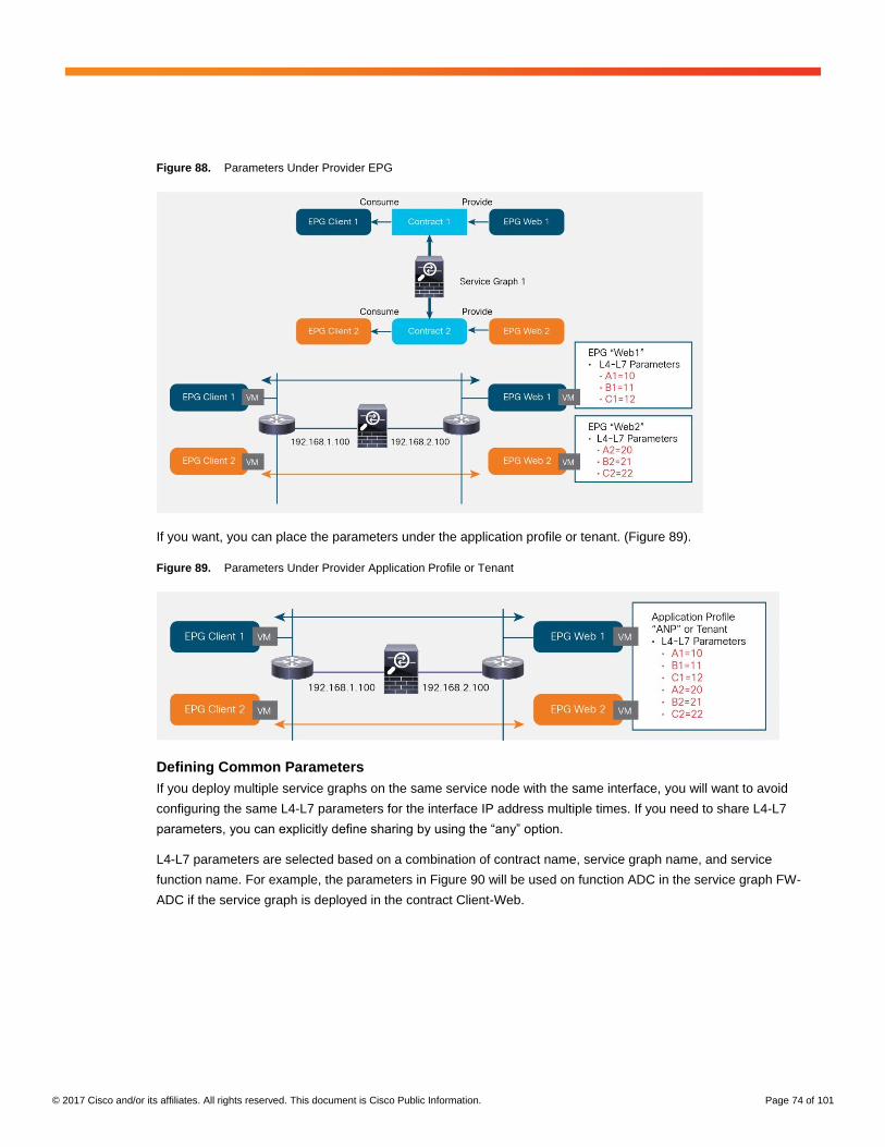
© 2017 Cisco and/or its affiliates. All rights reserved. This document is Cisco Public Information. Page 74 of 101
Figure 88. Parameters Under Provider EPG
If you want, you can place the parameters under the application profile or tenant. (Figure 89).
Figure 89. Parameters Under Provider Application Profile or Tenant
Defining Common Parameters
If you deploy multiple service graphs on the same service node with the same interface, you will want to avoid
configuring the same L4-L7 parameters for the interface IP address multiple times. If you need to share L4-L7
parameters, you can explicitly define sharing by using the “any” option.
L4-L7 parameters are selected based on a combination of contract name, service graph name, and service
function name. For example, the parameters in Figure 90 will be used on function ADC in the service graph FW-
ADC if the service graph is deployed in the contract Client-Web.

© 2017 Cisco and/or its affiliates. All rights reserved. This document is Cisco Public Information. Page 75 of 101
Figure 90. L4-L7 Parameter
You can use the “any” option for common parameters. In the example in Figure 91, regardless of the contract
name, the parameters will be used in function N1 in service graph NS-ADC. You can also use the “any” option with
the service graph and service function name.
Figure 91. Using the “Any” Parameter
Note: As of this writing, you can’t configure the “any” option from the GUI. You need to use the API to configure
this option.
Examples
In this example, you have a three-tier application with a load balancer, and you want to use the same load balancer
interface for different virtual IP addresses (Figure 92).
Figure 92. EPG, Contract, Service Graph Template, and L4-L7 Device Configuration

© 2017 Cisco and/or its affiliates. All rights reserved. This document is Cisco Public Information. Page 76 of 101
In this example (Figure 93):
● You use three contracts with the same service graph template.
● You deploy one virtual IP address for each service graph instance (three virtual IP addresses total).
● The interface configuration on the load balancer is common. The IP address is 192.168.3.200, and the
default gateway is 192.168.3.254.
Figure 93. Bridge Domain and VRF Configuration
By configuring the “any” option for the parameters for interface IP address 192.168.3.200 and default gateway
192.168.3.254, you don’t have to enter these values multiple times. Also, even if you remove the service graph
from one of contracts, the interface configuration remains. Other parameters, for example, the virtual IP address,
are deployed during each service graph rendering (Figure 94).
Figure 94. L4-L7 Parameters Under Application Profile Using the “any” Option
Figure 95 shows an example of deployment output. In this example, the service graph template is reused for three
contracts, and these all share the same interface.
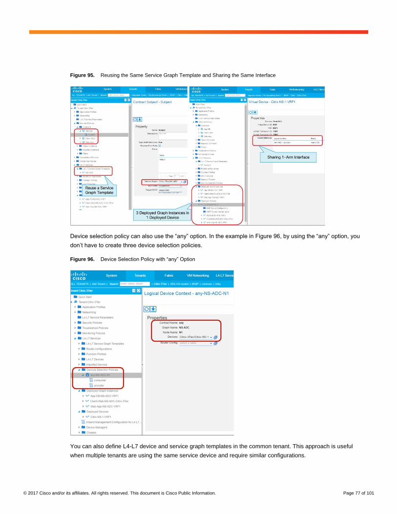
© 2017 Cisco and/or its affiliates. All rights reserved. This document is Cisco Public Information. Page 77 of 101
Figure 95. Reusing the Same Service Graph Template and Sharing the Same Interface
Device selection policy can also use the “any” option. In the example in Figure 96, by using the “any” option, you
don’t have to create three device selection policies.
Figure 96. Device Selection Policy with “any” Option
You can also define L4-L7 device and service graph templates in the common tenant. This approach is useful
when multiple tenants are using the same service device and require similar configurations.

© 2017 Cisco and/or its affiliates. All rights reserved. This document is Cisco Public Information. Page 78 of 101
Sample Tenant Configuration
<?xml version="1.0" encoding="UTF-8"?>
<imdata totalCount="1">
<fvTenant descr="Multiple VIPs, multiple EPGs" dn="uni/tn-Citrix-3Tier"
name="Citrix-3Tier" ownerKey="" ownerTag="">
<vnsLDevCtx ctrctNameOrLbl="any" descr="" graphNameOrLbl="NS-ADC"
name="" nodeNameOrLbl="N1">
<vnsRsLDevCtxToLDev tDn="uni/tn-Citrix-3Tier/lDevVip-Citrix-NS-
1"/>
<vnsLIfCtx connNameOrLbl="provider" descr="" name="provider">
<vnsRsLIfCtxToBD tDn="uni/tn-Citrix-3Tier/BD-BD3"/>
<vnsRsLIfCtxToLIf tDn="uni/tn-Citrix-3Tier/lDevVip-Citrix-
NS-1/lIf-provider"/>
</vnsLIfCtx>
<vnsLIfCtx connNameOrLbl="consumer" descr="" name="">
<vnsRsLIfCtxToBD tDn="uni/tn-Citrix-3Tier/BD-BD3"/>
<vnsRsLIfCtxToLIf tDn="uni/tn-Citrix-3Tier/lDevVip-Citrix-
NS-1/lIf-provider"/>
</vnsLIfCtx>
</vnsLDevCtx>
<vzBrCP descr="" name="Client-Web" ownerKey="" ownerTag=""
prio="unspecified" scope="tenant" targetDscp="unspecified">
<vzSubj consMatchT="AtleastOne" descr="" name="Subject"
prio="unspecified" provMatchT="AtleastOne" revFltPorts="yes"
targetDscp="unspecified">
<vzRsSubjFiltAtt tnVzFilterName="default"/>
<vzRsSubjGraphAtt tnVnsAbsGraphName="NS-ADC"/>
</vzSubj>
</vzBrCP>
<vzBrCP descr="" name="Web-App" ownerKey="" ownerTag=""
prio="unspecified" scope="context" targetDscp="unspecified">
<vzSubj consMatchT="AtleastOne" descr="" name="Subject"
prio="unspecified" provMatchT="AtleastOne" revFltPorts="yes"
targetDscp="unspecified">
<vzRsSubjFiltAtt tnVzFilterName="default"/>
<vzRsSubjGraphAtt tnVnsAbsGraphName="NS-ADC"/>
</vzSubj>
</vzBrCP>
<vzBrCP descr="" name="App-DB" ownerKey="" ownerTag=""
prio="unspecified" scope="context" targetDscp="unspecified">
<vzSubj consMatchT="AtleastOne" descr="" name="Subject"
prio="unspecified" provMatchT="AtleastOne" revFltPorts="yes"
targetDscp="unspecified">
<vzRsSubjFiltAtt tnVzFilterName="default"/>
<vzRsSubjGraphAtt tnVnsAbsGraphName="NS-ADC"/>
</vzSubj>
</vzBrCP>
<drawCont>

© 2017 Cisco and/or its affiliates. All rights reserved. This document is Cisco Public Information. Page 79 of 101
<drawInst info="{'{fvNetworking/vrf}-
{VRF1}':{'x':0,'y':0,'relPos':0,'prevPos':0}}" oDn="uni/tn-Citrix-3Tier"/>
</drawCont>
<vnsAbsGraph descr="" name="NS-ADC" ownerKey="" ownerTag=""
uiTemplateType="UNSPECIFIED">
<vnsAbsTermNodeCon descr="" name="T1" ownerKey="" ownerTag="">
<vnsAbsTermConn attNotify="no" descr="" name="1"
ownerKey="" ownerTag=""/>
<vnsInTerm descr="" name=""/>
<vnsOutTerm descr="" name=""/>
</vnsAbsTermNodeCon>
<vnsAbsTermNodeProv descr="" name="T2" ownerKey="" ownerTag="">
<vnsAbsTermConn attNotify="no" descr="" name="1"
ownerKey="" ownerTag=""/>
<vnsInTerm descr="" name=""/>
<vnsOutTerm descr="" name=""/>
</vnsAbsTermNodeProv>
<vnsAbsConnection adjType="L2" connDir="provider"
connType="external" descr="" name="C1" ownerKey="" ownerTag=""
unicastRoute="yes">
<vnsRsAbsConnectionConns tDn="uni/tn-Citrix-
3Tier/AbsGraph-NS-ADC/AbsTermNodeCon-T1/AbsTConn"/>
<vnsRsAbsConnectionConns tDn="uni/tn-Citrix-
3Tier/AbsGraph-NS-ADC/AbsNode-N1/AbsFConn-consumer"/>
</vnsAbsConnection>
<vnsAbsConnection adjType="L2" connDir="provider"
connType="external" descr="" name="C2" ownerKey="" ownerTag=""
unicastRoute="yes">
<vnsRsAbsConnectionConns tDn="uni/tn-Citrix-
3Tier/AbsGraph-NS-ADC/AbsTermNodeProv-T2/AbsTConn"/>
<vnsRsAbsConnectionConns tDn="uni/tn-Citrix-
3Tier/AbsGraph-NS-ADC/AbsNode-N1/AbsFConn-provider"/>
</vnsAbsConnection>
<vnsAbsNode descr="" funcTemplateType="ADC_ONE_ARM"
funcType="GoTo" managed="yes" name="N1" ownerKey="" ownerTag=""
sequenceNumber="0" shareEncap="no">
<vnsAbsFuncConn attNotify="no" descr="" name="consumer"
ownerKey="" ownerTag="">
<vnsRsMConnAtt tDn="uni/infra/mDev-Citrix-
NetScaler-1.0/mFunc-LoadBalancing/mConn-external"/>
</vnsAbsFuncConn>
<vnsAbsFuncConn attNotify="no" descr="" name="provider"
ownerKey="" ownerTag="">
<vnsRsMConnAtt tDn="uni/infra/mDev-Citrix-
NetScaler-1.0/mFunc-LoadBalancing/mConn-internal"/>
</vnsAbsFuncConn>
<vnsRsNodeToAbsFuncProf tDn="uni/tn-
common/absFuncProfContr/absFuncProfGrp-Citrix-FP/absFuncProf-Citrix-oneARM-FP"/>
<vnsRsNodeToLDev tDn="uni/tn-Citrix-3Tier/lDevVip-Citrix-
NS-1"/>

© 2017 Cisco and/or its affiliates. All rights reserved. This document is Cisco Public Information. Page 80 of 101
<vnsRsNodeToMFunc tDn="uni/infra/mDev-Citrix-NetScaler-
1.0/mFunc-LoadBalancing"/>
</vnsAbsNode>
</vnsAbsGraph>
<fvBD arpFlood="no" descr="" epMoveDetectMode=""
limitIpLearnToSubnets="no" llAddr="::" mac="00:22:BD:F8:19:FF"
multiDstPktAct="bd-flood" name="BD1" ownerKey="" ownerTag="" unicastRoute="yes"
unkMacUcastAct="proxy" unkMcastAct="flood" vmac="not-applicable">
<fvRsBDToNdP tnNdIfPolName=""/>
<fvRsCtx tnFvCtxName="VRF1"/>
<fvRsIgmpsn tnIgmpSnoopPolName=""/>
<fvSubnet ctrl="" descr="" ip="192.168.1.254/24" name=""
preferred="no" scope="private" virtual="no"/>
<fvRsBdToEpRet resolveAct="resolve" tnFvEpRetPolName=""/>
</fvBD>
<fvBD arpFlood="no" descr="" epMoveDetectMode=""
limitIpLearnToSubnets="no" llAddr="::" mac="00:22:BD:F8:19:FF"
multiDstPktAct="bd-flood" name="BD3" ownerKey="" ownerTag="" unicastRoute="yes"
unkMacUcastAct="proxy" unkMcastAct="flood" vmac="not-applicable">
<fvRsBDToNdP tnNdIfPolName=""/>
<fvRsCtx tnFvCtxName="VRF1"/>
<fvRsIgmpsn tnIgmpSnoopPolName=""/>
<fvSubnet ctrl="" descr="" ip="192.168.3.254/24" name=""
preferred="no" scope="private" virtual="no"/>
<fvRsBdToEpRet resolveAct="resolve" tnFvEpRetPolName=""/>
</fvBD>
<fvBD arpFlood="no" descr="" epMoveDetectMode=""
limitIpLearnToSubnets="no" llAddr="::" mac="00:22:BD:F8:19:FF"
multiDstPktAct="bd-flood" name="BD2" ownerKey="" ownerTag="" unicastRoute="yes"
unkMacUcastAct="proxy" unkMcastAct="flood" vmac="not-applicable">
<fvRsBDToNdP tnNdIfPolName=""/>
<fvRsCtx tnFvCtxName="VRF1"/>
<fvRsIgmpsn tnIgmpSnoopPolName=""/>
<fvSubnet ctrl="" descr="" ip="192.168.2.254/24" name=""
preferred="no" scope="private" virtual="no"/>
<fvRsBdToEpRet resolveAct="resolve" tnFvEpRetPolName=""/>
</fvBD>
<fvCtx descr="" knwMcastAct="permit" name="VRF1" ownerKey=""
ownerTag="" pcEnfDir="ingress" pcEnfPref="enforced">
<fvRsBgpCtxPol tnBgpCtxPolName=""/>
<fvRsCtxToExtRouteTagPol tnL3extRouteTagPolName=""/>
<fvRsOspfCtxPol tnOspfCtxPolName=""/>
<vzAny descr="" matchT="AtleastOne" name=""/>
<fvRsCtxToEpRet tnFvEpRetPolName=""/>
</fvCtx>
<fvAp descr="" name="ANP" ownerKey="" ownerTag="" prio="unspecified">
<fvAEPg descr="" isAttrBasedEPg="no" matchT="AtleastOne"
name="Web" pcEnfPref="unenforced" prio="unspecified">
<fvRsCons prio="unspecified" tnVzBrCPName="Web-App"/>

© 2017 Cisco and/or its affiliates. All rights reserved. This document is Cisco Public Information. Page 81 of 101
<fvRsDomAtt encap="unknown" instrImedcy="lazy"
primaryEncap="unknown" resImedcy="immediate" tDn="uni/vmmp-VMware/dom-ACI_vDS"/>
<fvRsBd tnFvBDName="BD2"/>
<fvRsCustQosPol tnQosCustomPolName=""/>
<fvRsProv matchT="AtleastOne" prio="unspecified"
tnVzBrCPName="Client-Web"/>
</fvAEPg>
<fvAEPg descr="" isAttrBasedEPg="no" matchT="AtleastOne"
name="Client" pcEnfPref="unenforced" prio="unspecified">
<fvRsCons prio="unspecified" tnVzBrCPName="Client-Web"/>
<fvRsDomAtt encap="unknown" instrImedcy="lazy"
primaryEncap="unknown" resImedcy="immediate" tDn="uni/vmmp-VMware/dom-ACI_vDS"/>
<fvRsBd tnFvBDName="BD1"/>
<fvRsCustQosPol tnQosCustomPolName=""/>
</fvAEPg>
<fvAEPg descr="" isAttrBasedEPg="no" matchT="AtleastOne"
name="App" pcEnfPref="unenforced" prio="unspecified">
<fvRsCons prio="unspecified" tnVzBrCPName="App-DB"/>
<fvRsDomAtt encap="unknown" instrImedcy="lazy"
primaryEncap="unknown" resImedcy="immediate" tDn="uni/vmmp-VMware/dom-ACI_vDS"/>
<fvRsBd tnFvBDName="BD2"/>
<fvRsCustQosPol tnQosCustomPolName=""/>
<fvRsProv matchT="AtleastOne" prio="unspecified"
tnVzBrCPName="Web-App"/>
</fvAEPg>
<fvAEPg descr="" isAttrBasedEPg="no" matchT="AtleastOne"
name="DB" pcEnfPref="unenforced" prio="unspecified">
<fvRsDomAtt encap="unknown" instrImedcy="lazy"
primaryEncap="unknown" resImedcy="immediate" tDn="uni/vmmp-VMware/dom-ACI_vDS"/>
<fvRsBd tnFvBDName="BD2"/>
<fvRsCustQosPol tnQosCustomPolName=""/>
<fvRsProv matchT="AtleastOne" prio="unspecified"
tnVzBrCPName="App-DB"/>
</fvAEPg>
<vnsFolderInst cardinality="unspecified" ctrctNameOrLbl="Client-
Web" devCtxLbl="" graphNameOrLbl="NS-ADC" key="lbvserver" locked="no"
name="lbvserver-web" nodeNameOrLbl="N1" scopedBy="epg">
<vnsParamInst cardinality="unspecified" key="ipv46"
locked="no" mandatory="no" name="ipv46" validation="" value="192.168.3.110"/>
<vnsParamInst cardinality="unspecified" key="port"
locked="no" mandatory="no" name="port" validation="" value="80"/>
<vnsParamInst cardinality="unspecified" key="name"
locked="no" mandatory="no" name="name" validation="" value="web1"/>
<vnsParamInst cardinality="unspecified" key="servicetype"
locked="no" mandatory="no" name="servicetype" validation="" value="TCP"/>
<vnsFolderInst cardinality="unspecified"
ctrctNameOrLbl="Client-Web" devCtxLbl="" graphNameOrLbl="NS-ADC"
key="lbvserver_servicegroup_binding" locked="no"
name="lbvserver_servicegroup_binding" nodeNameOrLbl="N1" scopedBy="epg">

© 2017 Cisco and/or its affiliates. All rights reserved. This document is Cisco Public Information. Page 82 of 101
<vnsCfgRelInst cardinality="unspecified"
key="servicename" locked="no" mandatory="no" name="servicename"
targetName="servicegroup_web"/>
</vnsFolderInst>
</vnsFolderInst>
<vnsFolderInst cardinality="unspecified" ctrctNameOrLbl="Web-
App" devCtxLbl="" graphNameOrLbl="NS-ADC" key="mFCngservice" locked="no"
name="mFCngservice-app" nodeNameOrLbl="N1" scopedBy="epg">
<vnsCfgRelInst cardinality="unspecified" key="service_key"
locked="no" mandatory="no" name="service_key" targetName="service-app"/>
</vnsFolderInst>
<vnsFolderInst cardinality="unspecified" ctrctNameOrLbl="App-DB"
devCtxLbl="" graphNameOrLbl="NS-ADC" key="servicegroup" locked="no"
name="servicegroup_DB" nodeNameOrLbl="N1" scopedBy="epg">
<vnsParamInst cardinality="unspecified" key="usip"
locked="no" mandatory="no" name="usip" validation="" value="NO"/>
<vnsParamInst cardinality="unspecified" key="port"
locked="no" mandatory="no" name="port" validation="" value="6001"/>
<vnsParamInst cardinality="unspecified"
key="servicegroupname" locked="no" mandatory="no" name="servicegroupname"
validation="" value="DB"/>
<vnsParamInst cardinality="unspecified" key="servicetype"
locked="no" mandatory="no" name="servicetype" validation="" value="TCP"/>
<vnsFolderInst cardinality="unspecified"
ctrctNameOrLbl="App-DB" devCtxLbl="" graphNameOrLbl="NS-ADC"
key="servicegroup_servicegroupmember_binding" locked="no"
name="servicegroup_servicegroupmember_binding" nodeNameOrLbl="N1" scopedBy="epg">
<vnsParamInst cardinality="unspecified" key="ip"
locked="no" mandatory="no" name="ip" validation="" value="192.168.2.30"/>
<vnsParamInst cardinality="unspecified" key="port"
locked="no" mandatory="no" name="port" validation="" value="6001"/>
</vnsFolderInst>
</vnsFolderInst>
<vnsFolderInst cardinality="unspecified" ctrctNameOrLbl="Web-
App" devCtxLbl="" graphNameOrLbl="NS-ADC" key="lbvserver" locked="no"
name="lbvserver-app" nodeNameOrLbl="N1" scopedBy="epg">
<vnsParamInst cardinality="unspecified" key="ipv46"
locked="no" mandatory="no" name="ipv46" validation="" value="192.168.3.120"/>
<vnsParamInst cardinality="unspecified" key="port"
locked="no" mandatory="no" name="port" validation="" value="5001"/>
<vnsParamInst cardinality="unspecified" key="name"
locked="no" mandatory="no" name="name" validation="" value="app1"/>
<vnsParamInst cardinality="unspecified" key="servicetype"
locked="no" mandatory="no" name="servicetype" validation="" value="TCP"/>
<vnsFolderInst cardinality="unspecified"
ctrctNameOrLbl="Web-App" devCtxLbl="" graphNameOrLbl="NS-ADC"
key="lbvserver_servicegroup_binding" locked="no"
name="lbvserver_servicegroup_binding" nodeNameOrLbl="N1" scopedBy="epg">
<vnsCfgRelInst cardinality="unspecified"
key="servicename" locked="no" mandatory="no" name="servicename"
targetName="servicegroup_app"/>
</vnsFolderInst>

© 2017 Cisco and/or its affiliates. All rights reserved. This document is Cisco Public Information. Page 83 of 101
</vnsFolderInst>
<vnsFolderInst cardinality="unspecified" ctrctNameOrLbl="Web-
App" devCtxLbl="" graphNameOrLbl="NS-ADC" key="mFCnglbvserver" locked="no"
name="mFCnglbvserver-app" nodeNameOrLbl="N1" scopedBy="epg">
<vnsCfgRelInst cardinality="unspecified"
key="lbvserver_key" locked="no" mandatory="no" name="lbvserver_key"
targetName="lbvserver-app"/>
</vnsFolderInst>
<vnsFolderInst cardinality="unspecified" ctrctNameOrLbl="Client-
Web" devCtxLbl="" graphNameOrLbl="NS-ADC" key="mFCngservicegroup" locked="no"
name="mFCngservicegroup-web" nodeNameOrLbl="N1" scopedBy="epg">
<vnsCfgRelInst cardinality="unspecified"
key="servicegroup_key" locked="no" mandatory="no" name="servicegroup_key"
targetName="servicegroup_web"/>
</vnsFolderInst>
<vnsFolderInst cardinality="unspecified" ctrctNameOrLbl="Client-
Web" devCtxLbl="" graphNameOrLbl="NS-ADC" key="mFCnglbvserver" locked="no"
name="mFCnglbvserver-web" nodeNameOrLbl="N1" scopedBy="epg">
<vnsCfgRelInst cardinality="unspecified"
key="lbvserver_key" locked="no" mandatory="no" name="lbvserver_key"
targetName="lbvserver-web"/>
</vnsFolderInst>
<vnsFolderInst cardinality="unspecified" ctrctNameOrLbl="App-DB"
devCtxLbl="" graphNameOrLbl="NS-ADC" key="Network" locked="no" name="network-DB"
nodeNameOrLbl="N1" scopedBy="epg">
<vnsFolderInst cardinality="unspecified"
ctrctNameOrLbl="App-DB" devCtxLbl="" graphNameOrLbl="NS-ADC" key="nsip"
locked="no" name="vip" nodeNameOrLbl="N1" scopedBy="epg">
<vnsParamInst cardinality="unspecified"
key="dynamicrouting" locked="no" mandatory="no" name="dynamicRouting"
validation="" value="DISABLED"/>
<vnsParamInst cardinality="unspecified"
key="ipaddress" locked="no" mandatory="no" name="ipaddress" validation=""
value="192.168.3.130"/>
<vnsParamInst cardinality="unspecified"
key="hostroute" locked="no" mandatory="no" name="hostroute" validation=""
value="DISABLED"/>
<vnsParamInst cardinality="unspecified"
key="netmask" locked="no" mandatory="no" name="netmask2" validation=""
value="255.255.255.0"/>
<vnsParamInst cardinality="unspecified" key="type"
locked="no" mandatory="no" name="type" validation="" value="VIP"/>
</vnsFolderInst>
</vnsFolderInst>
<vnsFolderInst cardinality="unspecified" ctrctNameOrLbl="Web-
App" devCtxLbl="" graphNameOrLbl="NS-ADC" key="service" locked="no"
name="service-app" nodeNameOrLbl="N1" scopedBy="epg">
<vnsParamInst cardinality="unspecified" key="ip"
locked="no" mandatory="no" name="ip" validation="" value="192.168.2.20"/>
<vnsParamInst cardinality="unspecified" key="port"
locked="no" mandatory="no" name="port" validation="" value="5001"/>
<vnsParamInst cardinality="unspecified" key="name"
locked="no" mandatory="no" name="name" validation="" value="app1"/>

© 2017 Cisco and/or its affiliates. All rights reserved. This document is Cisco Public Information. Page 84 of 101
<vnsParamInst cardinality="unspecified" key="servicetype"
locked="no" mandatory="no" name="servicetype" validation="" value="TCP"/>
</vnsFolderInst>
<vnsFolderInst cardinality="unspecified" ctrctNameOrLbl="Client-
Web" devCtxLbl="" graphNameOrLbl="NS-ADC" key="mFCngservice" locked="no"
name="mFCngservice-web" nodeNameOrLbl="N1" scopedBy="epg">
<vnsCfgRelInst cardinality="unspecified" key="service_key"
locked="no" mandatory="no" name="service_key" targetName="service-web"/>
</vnsFolderInst>
<vnsFolderInst cardinality="unspecified" ctrctNameOrLbl="Web-
App" devCtxLbl="" graphNameOrLbl="NS-ADC" key="servicegroup" locked="no"
name="servicegroup_app" nodeNameOrLbl="N1" scopedBy="epg">
<vnsParamInst cardinality="unspecified" key="usip"
locked="no" mandatory="no" name="usip" validation="" value="NO"/>
<vnsParamInst cardinality="unspecified" key="port"
locked="no" mandatory="no" name="port" validation="" value="5001"/>
<vnsParamInst cardinality="unspecified"
key="servicegroupname" locked="no" mandatory="no" name="servicegroupname"
validation="" value="app"/>
<vnsParamInst cardinality="unspecified" key="servicetype"
locked="no" mandatory="no" name="servicetype" validation="" value="TCP"/>
<vnsFolderInst cardinality="unspecified"
ctrctNameOrLbl="Web-App" devCtxLbl="" graphNameOrLbl="NS-ADC"
key="servicegroup_servicegroupmember_binding" locked="no"
name="servicegroup_servicegroupmember_binding" nodeNameOrLbl="N1" scopedBy="epg">
<vnsParamInst cardinality="unspecified" key="ip"
locked="no" mandatory="no" name="ip" validation="" value="192.168.2.20"/>
<vnsParamInst cardinality="unspecified" key="port"
locked="no" mandatory="no" name="port" validation="" value="5001"/>
</vnsFolderInst>
</vnsFolderInst>
<vnsFolderInst cardinality="unspecified" ctrctNameOrLbl="Client-
Web" devCtxLbl="" graphNameOrLbl="NS-ADC" key="service" locked="no"
name="service-web" nodeNameOrLbl="N1" scopedBy="epg">
<vnsParamInst cardinality="unspecified" key="ip"
locked="no" mandatory="no" name="ip" validation="" value="192.168.2.10"/>
<vnsParamInst cardinality="unspecified" key="port"
locked="no" mandatory="no" name="port" validation="" value="80"/>
<vnsParamInst cardinality="unspecified" key="name"
locked="no" mandatory="no" name="name" validation="" value="web1"/>
<vnsParamInst cardinality="unspecified" key="servicetype"
locked="no" mandatory="no" name="servicetype" validation="" value="TCP"/>
</vnsFolderInst>
<vnsFolderInst cardinality="unspecified" ctrctNameOrLbl="Web-
App" devCtxLbl="" graphNameOrLbl="NS-ADC" key="Network" locked="no"
name="network-app" nodeNameOrLbl="N1" scopedBy="epg">
<vnsFolderInst cardinality="unspecified"
ctrctNameOrLbl="Web-App" devCtxLbl="" graphNameOrLbl="NS-ADC" key="nsip"
locked="no" name="vip" nodeNameOrLbl="N1" scopedBy="epg">
<vnsParamInst cardinality="unspecified"
key="dynamicrouting" locked="no" mandatory="no" name="dynamicRouting"
validation="" value="DISABLED"/>

© 2017 Cisco and/or its affiliates. All rights reserved. This document is Cisco Public Information. Page 85 of 101
<vnsParamInst cardinality="unspecified"
key="ipaddress" locked="no" mandatory="no" name="ipaddress" validation=""
value="192.168.3.120"/>
<vnsParamInst cardinality="unspecified"
key="hostroute" locked="no" mandatory="no" name="hostroute" validation=""
value="DISABLED"/>
<vnsParamInst cardinality="unspecified"
key="netmask" locked="no" mandatory="no" name="netmask2" validation=""
value="255.255.255.0"/>
<vnsParamInst cardinality="unspecified" key="type"
locked="no" mandatory="no" name="type" validation="" value="VIP"/>
</vnsFolderInst>
</vnsFolderInst>
<vnsFolderInst cardinality="unspecified" ctrctNameOrLbl="Client-
Web" devCtxLbl="" graphNameOrLbl="NS-ADC" key="mFCngNetwork" locked="no"
name="mFCngnetwork-web" nodeNameOrLbl="N1" scopedBy="epg">
<vnsCfgRelInst cardinality="unspecified" key="Network_key"
locked="no" mandatory="no" name="Network_key" targetName="network-web/vip"/>
</vnsFolderInst>
<vnsFolderInst cardinality="unspecified" ctrctNameOrLbl="App-DB"
devCtxLbl="" graphNameOrLbl="NS-ADC" key="mFCngNetwork" locked="no"
name="mFCngnetwork-DB" nodeNameOrLbl="N1" scopedBy="epg">
<vnsCfgRelInst cardinality="unspecified" key="Network_key"
locked="no" mandatory="no" name="Network_key" targetName="network-DB/vip"/>
</vnsFolderInst>
<vnsFolderInst cardinality="unspecified" ctrctNameOrLbl="Client-
Web" devCtxLbl="" graphNameOrLbl="NS-ADC" key="Network" locked="no"
name="network-web" nodeNameOrLbl="N1" scopedBy="epg">
<vnsFolderInst cardinality="unspecified"
ctrctNameOrLbl="Client-Web" devCtxLbl="" graphNameOrLbl="NS-ADC" key="nsip"
locked="no" name="vip" nodeNameOrLbl="N1" scopedBy="epg">
<vnsParamInst cardinality="unspecified"
key="dynamicrouting" locked="no" mandatory="no" name="dynamicRouting"
validation="" value="DISABLED"/>
<vnsParamInst cardinality="unspecified"
key="ipaddress" locked="no" mandatory="no" name="ipaddress" validation=""
value="192.168.3.110"/>
<vnsParamInst cardinality="unspecified"
key="hostroute" locked="no" mandatory="no" name="hostroute" validation=""
value="DISABLED"/>
<vnsParamInst cardinality="unspecified"
key="netmask" locked="no" mandatory="no" name="netmask2" validation=""
value="255.255.255.0"/>
<vnsParamInst cardinality="unspecified" key="type"
locked="no" mandatory="no" name="type" validation="" value="VIP"/>
</vnsFolderInst>
</vnsFolderInst>
<vnsFolderInst cardinality="unspecified" ctrctNameOrLbl="any"
devCtxLbl="" graphNameOrLbl="NS-ADC" key="Network" locked="no" name="network"
nodeNameOrLbl="N1" scopedBy="epg">
<vnsFolderInst cardinality="unspecified"
ctrctNameOrLbl="any" devCtxLbl="" graphNameOrLbl="NS-ADC" key="route" locked="no"
name="route" nodeNameOrLbl="N1" scopedBy="epg">

© 2017 Cisco and/or its affiliates. All rights reserved. This document is Cisco Public Information. Page 86 of 101
<vnsParamInst cardinality="unspecified"
key="netmask" locked="no" mandatory="no" name="netmask" validation=""
value="255.255.0.0"/>
<vnsParamInst cardinality="unspecified"
key="network" locked="no" mandatory="no" name="network" validation=""
value="192.168.0.0"/>
<vnsParamInst cardinality="unspecified"
key="gateway" locked="no" mandatory="no" name="gateway" validation=""
value="192.168.3.254"/>
</vnsFolderInst>
<vnsFolderInst cardinality="unspecified"
ctrctNameOrLbl="any" devCtxLbl="" graphNameOrLbl="NS-ADC" key="nsip" locked="no"
name="internal_snip" nodeNameOrLbl="N1" scopedBy="epg">
<vnsParamInst cardinality="unspecified"
key="dynamicrouting" locked="no" mandatory="no" name="dynamicRouting"
validation="" value="DISABLED"/>
<vnsParamInst cardinality="unspecified"
key="ipaddress" locked="no" mandatory="no" name="ipaddress" validation=""
value="192.168.3.200"/>
<vnsParamInst cardinality="unspecified"
key="hostroute" locked="no" mandatory="no" name="hostroute" validation=""
value="DISABLED"/>
<vnsParamInst cardinality="unspecified"
key="netmask" locked="no" mandatory="no" name="netmask" validation=""
value="255.255.255.0"/>
<vnsParamInst cardinality="unspecified" key="type"
locked="no" mandatory="no" name="type" validation="" value="SNIP"/>
</vnsFolderInst>
</vnsFolderInst>
<vnsFolderInst cardinality="unspecified" ctrctNameOrLbl="any"
devCtxLbl="" graphNameOrLbl="NS-ADC" key="internal_network" locked="no"
name="internal_network" nodeNameOrLbl="N1" scopedBy="epg">
<vnsCfgRelInst cardinality="unspecified"
key="internal_network_key" locked="no" mandatory="no" name="internal_network_key"
targetName="network/internal_snip"/>
</vnsFolderInst>
<vnsFolderInst cardinality="unspecified" ctrctNameOrLbl="App-DB"
devCtxLbl="" graphNameOrLbl="NS-ADC" key="lbvserver" locked="no" name="lbvserver-
DB" nodeNameOrLbl="N1" scopedBy="epg">
<vnsParamInst cardinality="unspecified" key="ipv46"
locked="no" mandatory="no" name="ipv46" validation="" value="192.168.3.130"/>
<vnsParamInst cardinality="unspecified" key="port"
locked="no" mandatory="no" name="port" validation="" value="6001"/>
<vnsParamInst cardinality="unspecified" key="name"
locked="no" mandatory="no" name="name" validation="" value="DB1"/>
<vnsParamInst cardinality="unspecified" key="servicetype"
locked="no" mandatory="no" name="servicetype" validation="" value="TCP"/>
<vnsFolderInst cardinality="unspecified"
ctrctNameOrLbl="App-DB" devCtxLbl="" graphNameOrLbl="NS-ADC"
key="lbvserver_servicegroup_binding" locked="no"
name="lbvserver_servicegroup_binding" nodeNameOrLbl="N1" scopedBy="epg">
<vnsCfgRelInst cardinality="unspecified"
key="servicename" locked="no" mandatory="no" name="servicename"
targetName="servicegroup_DB"/>

© 2017 Cisco and/or its affiliates. All rights reserved. This document is Cisco Public Information. Page 87 of 101
</vnsFolderInst>
</vnsFolderInst>
<vnsFolderInst cardinality="unspecified" ctrctNameOrLbl="App-DB"
devCtxLbl="" graphNameOrLbl="NS-ADC" key="mFCngservicegroup" locked="no"
name="mFCngservicegroup-DB" nodeNameOrLbl="N1" scopedBy="epg">
<vnsCfgRelInst cardinality="unspecified"
key="servicegroup_key" locked="no" mandatory="no" name="servicegroup_key"
targetName="servicegroup_DB"/>
</vnsFolderInst>
<vnsFolderInst cardinality="unspecified" ctrctNameOrLbl="App-DB"
devCtxLbl="" graphNameOrLbl="NS-ADC" key="service" locked="no" name="service-DB"
nodeNameOrLbl="N1" scopedBy="epg">
<vnsParamInst cardinality="unspecified" key="ip"
locked="no" mandatory="no" name="ip" validation="" value="192.168.2.30"/>
<vnsParamInst cardinality="unspecified" key="port"
locked="no" mandatory="no" name="port" validation="" value="6001"/>
<vnsParamInst cardinality="unspecified" key="name"
locked="no" mandatory="no" name="name" validation="" value="DB1"/>
<vnsParamInst cardinality="unspecified" key="servicetype"
locked="no" mandatory="no" name="servicetype" validation="" value="TCP"/>
</vnsFolderInst>
<vnsFolderInst cardinality="unspecified" ctrctNameOrLbl="Client-
Web" devCtxLbl="" graphNameOrLbl="NS-ADC" key="servicegroup" locked="no"
name="servicegroup_web" nodeNameOrLbl="N1" scopedBy="epg">
<vnsParamInst cardinality="unspecified" key="usip"
locked="no" mandatory="no" name="usip" validation="" value="NO"/>
<vnsParamInst cardinality="unspecified" key="port"
locked="no" mandatory="no" name="port" validation="" value="80"/>
<vnsParamInst cardinality="unspecified"
key="servicegroupname" locked="no" mandatory="no" name="servicegroupname"
validation="" value="web"/>
<vnsParamInst cardinality="unspecified" key="servicetype"
locked="no" mandatory="no" name="servicetype" validation="" value="TCP"/>
<vnsFolderInst cardinality="unspecified"
ctrctNameOrLbl="Client-Web" devCtxLbl="" graphNameOrLbl="NS-ADC"
key="servicegroup_servicegroupmember_binding" locked="no"
name="servicegroup_servicegroupmember_binding" nodeNameOrLbl="N1" scopedBy="epg">
<vnsParamInst cardinality="unspecified" key="ip"
locked="no" mandatory="no" name="ip" validation="" value="192.168.2.10"/>
<vnsParamInst cardinality="unspecified" key="port"
locked="no" mandatory="no" name="port" validation="" value="80"/>
</vnsFolderInst>
</vnsFolderInst>
<vnsFolderInst cardinality="unspecified" ctrctNameOrLbl="App-DB"
devCtxLbl="" graphNameOrLbl="NS-ADC" key="mFCnglbvserver" locked="no"
name="mFCnglbvserver-DB" nodeNameOrLbl="N1" scopedBy="epg">
<vnsCfgRelInst cardinality="unspecified"
key="lbvserver_key" locked="no" mandatory="no" name="lbvserver_key"
targetName="lbvserver-DB"/>
</vnsFolderInst>

© 2017 Cisco and/or its affiliates. All rights reserved. This document is Cisco Public Information. Page 88 of 101
<vnsFolderInst cardinality="unspecified" ctrctNameOrLbl="App-DB"
devCtxLbl="" graphNameOrLbl="NS-ADC" key="mFCngservice" locked="no"
name="mFCngservice-DB" nodeNameOrLbl="N1" scopedBy="epg">
<vnsCfgRelInst cardinality="unspecified" key="service_key"
locked="no" mandatory="no" name="service_key" targetName="service-DB"/>
</vnsFolderInst>
<vnsFolderInst cardinality="unspecified" ctrctNameOrLbl="Web-
App" devCtxLbl="" graphNameOrLbl="NS-ADC" key="mFCngNetwork" locked="no"
name="mFCngnetwork-app" nodeNameOrLbl="N1" scopedBy="epg">
<vnsCfgRelInst cardinality="unspecified" key="Network_key"
locked="no" mandatory="no" name="Network_key" targetName="network-app/vip"/>
</vnsFolderInst>
<vnsFolderInst cardinality="unspecified" ctrctNameOrLbl="Web-
App" devCtxLbl="" graphNameOrLbl="NS-ADC" key="mFCngservicegroup" locked="no"
name="mFCngservicegroup-app" nodeNameOrLbl="N1" scopedBy="epg">
<vnsCfgRelInst cardinality="unspecified"
key="servicegroup_key" locked="no" mandatory="no" name="servicegroup_key"
targetName="servicegroup_app"/>
</vnsFolderInst>
</fvAp>
<fvRsTenantMonPol tnMonEPGPolName=""/>
<vnsLDevVip contextAware="single-Context" devtype="VIRTUAL"
funcType="GoTo" managed="yes" mode="legacy-Mode" name="Citrix-NS-1"
svcType="ADC">
<vnsCCred name="username" value="nsroot"/>
<vnsRsMDevAtt tDn="uni/infra/mDev-Citrix-NetScaler-1.0"/>
<vnsCCredSecret name="password"/>
<vnsCMgmt host="172.31.185.3" name="" port="80"/>
<vnsRsALDevToDomP tDn="uni/vmmp-VMware/dom-ACI_vDS"/>
<vnsCDev devCtxLbl="" name="Citrix-NS-1_Device_1"
vcenterName="vCenter-5.5" vmName="Citrix-NS-1">
<vnsCCred name="username" value="nsroot"/>
<vnsCCredSecret name="password"/>
<vnsCMgmt host="172.31.185.3" name="" port="80"/>
<vnsCIf name="1_1" vnicName="Network adapter 2"/>
<vnsCIf name="1_2" vnicName="Network adapter 3"/>
<vnsRsCDevToCtrlrP tDn="uni/vmmp-VMware/dom-ACI_vDS/ctrlr-
vCenter-5.5"/>
</vnsCDev>
<vnsLIf encap="unknown" name="provider">
<vnsRsMetaIf isConAndProv="no" tDn="uni/infra/mDev-Citrix-
NetScaler-1.0/mIfLbl-inside"/>
<vnsRsCIfAttN tDn="uni/tn-Citrix-3Tier/lDevVip-Citrix-NS-
1/cDev-Citrix-NS-1_Device_1/cIf-[1_2]"/>
</vnsLIf>
<vnsLIf encap="unknown" name="consumer">
<vnsRsMetaIf isConAndProv="no" tDn="uni/infra/mDev-Citrix-
NetScaler-1.0/mIfLbl-outside"/>
<vnsRsCIfAttN tDn="uni/tn-Citrix-3Tier/lDevVip-Citrix-NS-
1/cDev-Citrix-NS-1_Device_1/cIf-[1_1]"/>

© 2017 Cisco and/or its affiliates. All rights reserved. This document is Cisco Public Information. Page 89 of 101
</vnsLIf>
</vnsLDevVip>
</fvTenant>
</imdata>
Example
This section provides an example that shows how to deploy a service graph with a Cisco ASA firewall. The
previous sections presented the steps for configuring an L4-L7 service graph common to all L4-L7 services and
that also applies to the ASA firewall. This section completes the previous section with information specific to ASA.
Figure 97 illustrates the deployment example.
Figure 97. Cisco ASA Deployed in Transparent Mode
Management Configuration on Cisco ASA and ASAv
Perform the following steps on the ASA or ASAv:
1. Verify that HTTP and HTTPS management is defined.
2. Verify that Secure Shell (SSH) access is configured.
3. Verify that you can log in to the ASA through SSH.
The ASA doesn’t use the concept of a management VRF instance, so you should use the routing table on the ASA
for traffic forwarding, not for management traffic. Therefore, you should have a management station on the same
subnet as the management port of the ASA, or you should use the instructions for in-band management.
Fabric and Access Policy Configuration
Perform the following steps in Cisco ACI:
● If you are using a physical ASA device, define the physical domain for the ASA ports with a dynamic VLAN
pool.
● If you are using ASAv, define the virtual domain with a dynamic VLAN pool.
As with the other Cisco ACI configurations, you should define the Attachable Entity Profile (AEP), the policy group,
and so on.
If you are using a physical ASA, you likely will want to use a vPC to connect it to Cisco ACI. In this case, you need
to create a policy group type of vPC.

© 2017 Cisco and/or its affiliates. All rights reserved. This document is Cisco Public Information. Page 90 of 101
Make sure that the Link Aggregation Control Protocol (LACP) policy defines the maximum LACP value as 8
(at the time of this writing, an error in the device package on the ASA side requires the maximum LACP value to be
set to 8).
Data Path Configuration for Transparent Mode
As previously explained, you need to configure the data path for transparent mode as follows:
● Create two bridge domains.
● Configure unknown unicast flooding, ARP flooding, and unicast routing as necessary.
The following list shows the configurations for an ASA deployed in transparent mode:
● Bridge domain outside or client facing (consumer side)
◦ Enable unicast routing.
◦ Enable unknown unicast flooding.
◦ Enable ARP flooding.
◦ The subnet definition on the bridge domain is the default gateway for the servers.
● Bridge domain internal or server facing (provider side):
◦ Disable unicast routing.
◦ Enable unknown unicast flooding.
◦ Enable ARP flooding.
◦ The subnet definition on the bridge domain is irrelevant.
You need to associate both bridge domains with a VRF instance to make the Cisco ACI object model consistent.
You then create EPGs for the client and server sides, create a template, apply the template, and provide the L4-L7
parameters.
The next section explains which parameters to configure.
After you apply the service graph template, if you expect the outside bridge domain to perform the default gateway
function for the firewall, you need to change the adjacency type for the connector of the external interface of the
ASA to Layer 3. You also need to enable unicast routing. You need to take these steps to bring up the Switch
Virtual Interface (SVI) on the bridge domain (Figure 98).

© 2017 Cisco and/or its affiliates. All rights reserved. This document is Cisco Public Information. Page 91 of 101
Figure 98. Configuration of the Layer 3 Connector
L4-L7 Parameters for Transparent Mode
Even if all the required parameters are listed on the Required Parameters tab, you should select the All Parameters
tab (Figure 99). Here you should configure externalIf and internalIf.
Figure 99. Entering L4-L7 Parameters for Cisco ASA
You then need to create a bridge group to implement transparent mode, and you need to define an IP address for
the bridge group. You can perform this configuration from the All Parameters tab. The IP address and mask that
you configure in the parameters must follow the format used in this example: 10.10.10.5/255.255.255.128. The
format is “/” without spaces, followed by the mask and not just a mask length (for example, not just /25).

© 2017 Cisco and/or its affiliates. All rights reserved. This document is Cisco Public Information. Page 92 of 101
XML Configuration for Cisco ASAv Deployed in Transparent Mode
This section shows the XML configuration for the ASAv deployed in transparent mode.
Creating the Tenant
<polUni>
<fvTenant name="Sales">
<!-- Creates VRF -->
<fvCtx name="Salesctx1"/>
<!-- bridge domain -->
<fvBD name="SalesBDOutside" arpFlood="yes" unicastRoute="yes"
unkMacUcastAct="flood" unkMcastAct="flood">
<fvRsCtx tnFvCtxName="Salesctx1" />
<fvSubnet ip="30.0.0.2/24" />
</fvBD>
<!-- bridge domain -->
<fvBD name="SalesBDInside" arpFlood="yes" unicastRoute="no"
unkMacUcastAct="flood" unkMcastAct="flood">
<fvRsCtx tnFvCtxName="Salesctx1" />
</fvBD>
<fvAp name="orderingtool">
<fvAEPg matchT="AtleastOne" name="app" >
<fvRsDomAtt instrImedcy="lazy" resImedcy="immediate" tDn="uni/vmmp-
VMware/dom-vCenterACI2">
</fvRsDomAtt>
<fvRsBd tnFvBDName="SalesBDInside"/>
</fvAEPg>
</fvAp>
</fvTenant>
</polUni>
Creating the Contract
<polUni>
<fvTenant dn="uni/tn-Sales" name="Sales">
<!-- setting scope to Tenant so that the contract can also be used across
VRFs if needed -->
<vzBrCP name="webtoapp" scope="tenant">
<vzSubj name="alltraffic" provMatchT="AtleastOne" revFltPorts="yes">
<vzRsSubjFiltAtt tnVzFilterName="default"/>
</vzSubj>
</vzBrCP>
<fvAp name="orderingtool">
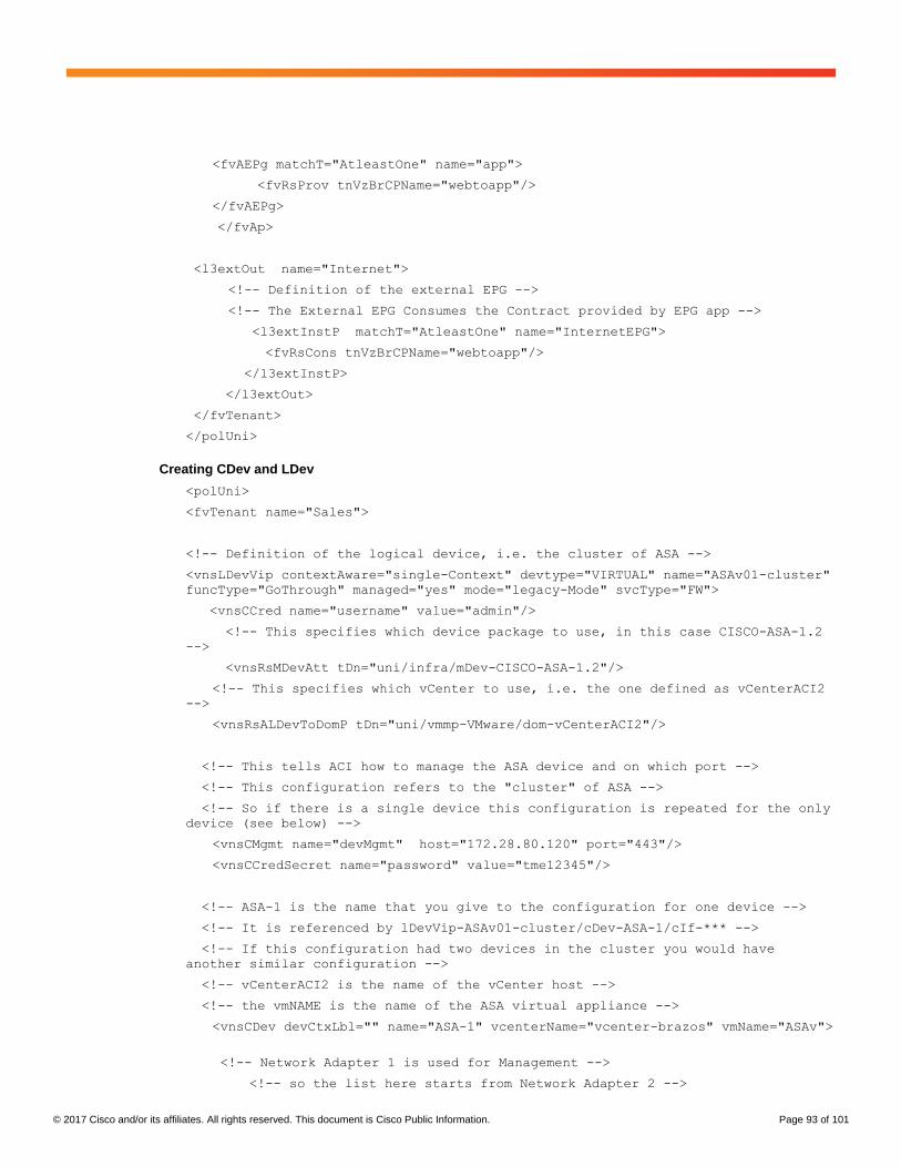
© 2017 Cisco and/or its affiliates. All rights reserved. This document is Cisco Public Information. Page 93 of 101
<fvAEPg matchT="AtleastOne" name="app">
<fvRsProv tnVzBrCPName="webtoapp"/>
</fvAEPg>
</fvAp>
<l3extOut name="Internet">
<!-- Definition of the external EPG -->
<!-- The External EPG Consumes the Contract provided by EPG app -->
<l3extInstP matchT="AtleastOne" name="InternetEPG">
<fvRsCons tnVzBrCPName="webtoapp"/>
</l3extInstP>
</l3extOut>
</fvTenant>
</polUni>
Creating CDev and LDev
<polUni>
<fvTenant name="Sales">
<!-- Definition of the logical device, i.e. the cluster of ASA -->
<vnsLDevVip contextAware="single-Context" devtype="VIRTUAL" name="ASAv01-cluster"
funcType="GoThrough" managed="yes" mode="legacy-Mode" svcType="FW">
<vnsCCred name="username" value="admin"/>
<!-- This specifies which device package to use, in this case CISCO-ASA-1.2
-->
<vnsRsMDevAtt tDn="uni/infra/mDev-CISCO-ASA-1.2"/>
<!-- This specifies which vCenter to use, i.e. the one defined as vCenterACI2
-->
<vnsRsALDevToDomP tDn="uni/vmmp-VMware/dom-vCenterACI2"/>
<!-- This tells ACI how to manage the ASA device and on which port -->
<!-- This configuration refers to the "cluster" of ASA -->
<!-- So if there is a single device this configuration is repeated for the only
device (see below) -->
<vnsCMgmt name="devMgmt" host="172.28.80.120" port="443"/>
<vnsCCredSecret name="password" value="tme12345"/>
<!-- ASA-1 is the name that you give to the configuration for one device -->
<!-- It is referenced by lDevVip-ASAv01-cluster/cDev-ASA-1/cIf-*** -->
<!-- If this configuration had two devices in the cluster you would have
another similar configuration -->
<!-- vCenterACI2 is the name of the vCenter host -->
<!-- the vmNAME is the name of the ASA virtual appliance -->
<vnsCDev devCtxLbl="" name="ASA-1" vcenterName="vcenter-brazos" vmName="ASAv">
<!-- Network Adapter 1 is used for Management -->
<!-- so the list here starts from Network Adapter 2 -->

© 2017 Cisco and/or its affiliates. All rights reserved. This document is Cisco Public Information. Page 94 of 101
<!-- GigabitEthernet0/0 is not an arbitrary name, it indicates the
inteface from ASA -->
<!-- This is telling ACI that interface Network Adapter 2 is mapped to
Gig0/0 in ASA -->
<vnsCIf name="GigabitEthernet0/0" vnicName="Network adapter 2"/>
<!-- GigabitEthernet0/1 is not an arbitrary name, it indicates the
inteface from ASA -->
<!-- This is telling ACI that interface Network Adapter 3 is mapped to
Gig0/1 in ASA -->
<vnsCIf name="GigabitEthernet0/1" vnicName="Network adapter 3"/>
<!-- Because there's a single device in this cluster this configuration is
identical to the previous one -->
<vnsCMgmt name="devMgmt" host="172.28.80.120" port="443"/>
<vnsCCred name="username" value="admin"/>
<vnsCCredSecret name="password" value="tme12345"/>
</vnsCDev>
<!-- The logical interface is the abstraction of the interface that represents
the cluster -->
<!-- in the case of a cluster with a single device, the logical interface
includes -->
<!-- the interface of the "concrete" device -->
<vnsLIf name="ASAClusterExt">
<vnsRsMetaIf tDn="uni/infra/mDev-CISCO-ASA-1.2/mIfLbl-external"/>
<!-- lDevVip-ASAv01-cluster uses the name of the LDev that you previously
defined -->
<vnsRsCIfAtt tDn="uni/tn-Sales/lDevVip-ASAv01-cluster/cDev-ASA-1/cIf-
[GigabitEthernet0/0]"/>
</vnsLIf>
<vnsLIf name="ASAClusterInt">
<vnsRsMetaIf tDn="uni/infra/mDev-CISCO-ASA-1.2/mIfLbl-internal"/>
<!-- lDevVip-ASAv01-cluster uses the name of the LDev that you previously
defined -->
<vnsRsCIfAtt tDn="uni/tn-Sales/lDevVip-ASAv01-cluster/cDev-ASA-1/cIf-
[GigabitEthernet0/1]"/>
</vnsLIf>
</vnsLDevVip>
</fvTenant>
</polUni>
Creating the Service Graph Template
<polUni>
<fvTenant name="Sales">
<!-- This is the name of the graph -->
<!-- it is referenced when you associate with the contract -->

© 2017 Cisco and/or its affiliates. All rights reserved. This document is Cisco Public Information. Page 95 of 101
<vnsAbsGraph name="FW-bridged">
<!-- This is the Outside "connector" of the graph -->
<!-- The name is referenced by AbsTermNodeProv-ServerSide/AbsTConn -->
<vnsAbsTermNodeCon name="OutsideTerminalConnector">
<vnsAbsTermConn attNotify="no" name="1"/>
<vnsInTerm name="input-terminal"/>
<vnsOutTerm name="output-terminal"/>
</vnsAbsTermNodeCon>
<!-- This is the Inside "connector" of the graph -->
<!-- The name is referenced by AbsTermNodeCon-ClientSide/AbsTConn -->
<vnsAbsTermNodeProv name="InsideTerminalConnector">
<vnsAbsTermConn attNotify="no" name="1" />
<vnsInTerm name="input-terminal"/>
<vnsOutTerm name="output-terminal"/>
</vnsAbsTermNodeProv>
<!-- This defines the name of the node in the graph -->
<!-- The name is referenced by "AbsNode-ASA-1-node/AbsFConn-****" -->
<vnsAbsNode funcTemplateType="FW_TRANS" funcType="GoThrough" name="ASA-1-
node">
<!-- This specifies which function this is -->
<vnsRsNodeToMFunc tDn="uni/infra/mDev-CISCO-ASA-1.2/mFunc-Firewall"/>
<!-- This is the name of the connectivity point of the node -->
<!-- the name is referenced by AbsNode-ASA-1-node/AbsFConn-ASAnodeoutside -->
<vnsAbsFuncConn attNotify="no" name="ASAnodeoutside">
<!-- This is the Metadevice information i.e. the mConnector -->
<!-- "external" is not an arbitrary name, it is the definition of the type of
interface -->
<!-- and it has a precise meaning in the meta device -->
<vnsRsMConnAtt tDn="uni/infra/mDev-CISCO-ASA-1.2/mFunc-Firewall/mConn-
external"/>
</vnsAbsFuncConn>
<!-- This is the name of the connectivity point of the node -->
<!-- the name is referenced by "AbsNode-ASA-1-node/AbsFConn-ASAnodeinside" -->
<vnsAbsFuncConn attNotify="no" name="ASAnodeinside">
<!-- This is the Metadevice information i.e. the mConnector -->
<!-- "internal" is not an arbitrary name, it is the definition of the
type of interface -->
<!-- and it has a precise meaning in the meta device -->

© 2017 Cisco and/or its affiliates. All rights reserved. This document is Cisco Public Information. Page 96 of 101
<vnsRsMConnAtt tDn="uni/infra/mDev-CISCO-ASA-1.2/mFunc-Firewall/mConn-
internal"/>
</vnsAbsFuncConn>
</vnsAbsNode>
<!-- Makes it possible to enable routing on the BD that it connects to -->
<vnsAbsConnection adjType="L3" connType="external" name="ArbitraryName1"
unicastRoute="yes">
<vnsRsAbsConnectionConns tDn="uni/tn-Sales/AbsGraph-FW-bridged/AbsNode-ASA-1-
node/AbsFConn-ASAnodeoutside"/>
<vnsRsAbsConnectionConns tDn="uni/tn-Sales/AbsGraph-FW-
bridged/AbsTermNodeCon-OutsideTerminalConnector/AbsTConn"/>
</vnsAbsConnection>
<vnsAbsConnection adjType="L2" connType="external" name="ArbitraryName2"
unicastRoute="no">
<vnsRsAbsConnectionConns tDn="uni/tn-Sales/AbsGraph-FW-bridged/AbsNode-ASA-1-
node/AbsFConn-ASAnodeinside"/>
<vnsRsAbsConnectionConns tDn="uni/tn-Sales/AbsGraph-FW-
bridged/AbsTermNodeProv-InsideTerminalConnector/AbsTConn"/>
</vnsAbsConnection>
</vnsAbsGraph>
</fvTenant>
</polUni>
Configuring Device Selection Policy
<polUni>
<fvTenant name="Sales">
<!-- here we need to match the contract name -->
<!-- the graph name -->
<!-- the node name in the graph -->
<!-- and indicate which interface maps to which BD -->
<!-- nodeNameOrLbl refers to the name of the node as defined the Abstract Graph
-->
<vnsLDevCtx ctrctNameOrLbl="webtoapp" graphNameOrLbl="FW-bridged"
nodeNameOrLbl="ASA-1-node">
<!-- ASAv01-cluster is the name of the Logical Device i.e. of the Cluster of ASAv
-->
<vnsRsLDevCtxToLDev tDn="uni/tn-Sales/lDevVip-ASAv01-cluster"/>
<!-- Connector name is defined in the Abstract Graph -->
<!-- It is the function connector -->
<vnsLIfCtx connNameOrLbl="ASAnodeoutside" name="line1">
<!-- ASAv01-cluster is the name of the Logical Device -->

© 2017 Cisco and/or its affiliates. All rights reserved. This document is Cisco Public Information. Page 97 of 101
<!-- The Lif is the "cluster" interface name, i.e. the abstract interface -->
<!-- that can map to either ASAv in the cluster -->
<vnsRsLIfCtxToLIf tDn="uni/tn-Sales/lDevVip-ASAv01-cluster/lIf-
ASAClusterExt"/>
<!-- This is the outside BD-->
<vnsRsLIfCtxToBD tDn="uni/tn-Sales/BD-SalesBDOutside"/>
</vnsLIfCtx>
<vnsLIfCtx connNameOrLbl="ASAnodeinside" name="line2">
<vnsRsLIfCtxToLIf tDn="uni/tn-Sales/lDevVip-ASAv01-cluster/lIf-
ASAClusterInt"/>
<vnsRsLIfCtxToBD tDn="uni/tn-Sales/BD-SalesBDInside"/>
</vnsLIfCtx>
</vnsLDevCtx>
</fvTenant>
</polUni>
Configuring the Provider EPG with L4-L7 Parameters
<polUni>
<fvTenant name="Sales">
<!-- Application Profile -->
<fvAp name="orderingtool">
<!-- Inside: app -->
<fvAEPg name="app">
<!-- RELATION TO THE EXTERNAL AND INTERNAL INTERFACES -->
<vnsFolderInst ctrctNameOrLbl="webtoapp" graphNameOrLbl="FW-bridged"
key="ExIntfConfigRelFolder" name="ExtConfig" nodeNameOrLbl="ASA-1-node" >
<vnsCfgRelInst key="ExIntfConfigRel" name="ExtConfigrel"
targetName="externalIf"/>
</vnsFolderInst>
<vnsFolderInst ctrctNameOrLbl="webtoapp" graphNameOrLbl="FW-bridged"
key="InIntfConfigRelFolder" name="IntConfig" nodeNameOrLbl="ASA-1-node" >
<vnsCfgRelInst key="InIntfConfigRel" name="InConfigrel"
targetName="internalIf"/>
</vnsFolderInst>
<!-- ACL DEFINITION, ACL NAME "access-list-inbound" -->
<vnsFolderInst ctrctNameOrLbl="webtoapp" graphNameOrLbl="FW-bridged"
key="AccessList" name="access-list-inbound" nodeNameOrLbl="ASA-1-node" >
<!-- ACE "permit-ssh" -->
<vnsFolderInst ctrctNameOrLbl="webtoapp" graphNameOrLbl="FW-bridged"
key="AccessControlEntry" name="permit-ssh" nodeNameOrLbl="ASA-1-node" >
<vnsParamInst key="order" name="order1" value="10"/>

© 2017 Cisco and/or its affiliates. All rights reserved. This document is Cisco Public Information. Page 98 of 101
<!-- protocol -->
<vnsFolderInst ctrctNameOrLbl="webtoapp" graphNameOrLbl="FW-bridged"
key="protocol" name="tcp" nodeNameOrLbl="ASA-1-node" >
<vnsParamInst key="name_number" name="tcp" value="tcp"/>
</vnsFolderInst>
<!-- source address -->
<vnsFolderInst ctrctNameOrLbl="webtoapp" graphNameOrLbl="FW-bridged"
key="source_address" name="src-address" nodeNameOrLbl="ASA-1-node" >
<vnsParamInst key="any" name="any" value="any"/>
</vnsFolderInst>
<!-- destination address -->
<vnsFolderInst ctrctNameOrLbl="webtoapp" graphNameOrLbl="FW-bridged"
key="destination_address" name="dest-address" nodeNameOrLbl="ASA-1-node" >
<vnsParamInst key="any" name="any" value="any"/>
</vnsFolderInst>
<!-- destination L4 port -->
<vnsFolderInst ctrctNameOrLbl="webtoapp" graphNameOrLbl="FW-bridged"
key="destination_service" name="dest-service" nodeNameOrLbl="ASA-1-node" >
<vnsParamInst key="operator" name="op" value="eq"/>
<vnsParamInst key="low_port" name="port" value="22"/>
</vnsFolderInst>
<!-- action permit or deny -->
<vnsParamInst key="action" name="action-permit" value="permit"/>
</vnsFolderInst>
<!-- ACE "permit-icmp" -->
<vnsFolderInst ctrctNameOrLbl="webtoapp" graphNameOrLbl="FW-bridged"
key="AccessControlEntry" name="permit-icmp" nodeNameOrLbl="ASA-1-node" >
<vnsParamInst key="order" name="order1" value="10"/>
<!-- protocol -->
<vnsFolderInst ctrctNameOrLbl="webtoapp" graphNameOrLbl="FW-bridged"
key="protocol" name="icmp" nodeNameOrLbl="ASA-1-node" >
<vnsParamInst key="name_number" name="icmp" value="icmp"/>
</vnsFolderInst>
<!-- source address -->
<vnsFolderInst ctrctNameOrLbl="webtoapp" graphNameOrLbl="FW-bridged"
key="source_address" name="src-address" nodeNameOrLbl="ASA-1-node" >
<vnsParamInst key="any" name="any" value="any"/>
</vnsFolderInst>
<!-- destination address -->
<vnsFolderInst ctrctNameOrLbl="webtoapp" graphNameOrLbl="FW-bridged"
key="destination_address" name="dest-address" nodeNameOrLbl="ASA-1-node" >
<vnsParamInst key="any" name="any" value="any"/>
</vnsFolderInst>
<!-- action -->
<vnsParamInst key="action" name="action-permit" value="permit"/>
</vnsFolderInst>
</vnsFolderInst>

© 2017 Cisco and/or its affiliates. All rights reserved. This document is Cisco Public Information. Page 99 of 101
<!-- BRIDGE-GROUP 1 -->
<vnsFolderInst ctrctNameOrLbl="webtoapp" graphNameOrLbl="FW-bridged"
key="BridgeGroupIntf" name="1" nodeNameOrLbl="ASA-1-node" scopedBy="epg">
<vnsParamInst key="ipv6_nd_dad_attempts" name="ipv6_nd_dad_attempts"
validation="" value="1"/>
<!-- IP ADDRESS-->
<vnsFolderInst ctrctNameOrLbl="webtoapp" graphNameOrLbl="FW-bridged"
key="IPv4Address" name="IPv4Address" nodeNameOrLbl="ASA-1-node" scopedBy="epg">
<vnsParamInst key="ipv4_address" name="ipv4_address" validation=""
value="30.0.0.254/255.255.255.0"/>
</vnsFolderInst>
</vnsFolderInst>
<!-- EXTERNAL INTERFACE -->
<vnsFolderInst ctrctNameOrLbl="webtoapp" graphNameOrLbl="FW-bridged"
key="Interface" name="externalIf" nodeNameOrLbl="ASA-1-node" >
<vnsFolderInst ctrctNameOrLbl="webtoapp" graphNameOrLbl="FW-bridged"
key="InterfaceConfig" name="externalIfCfg" nodeNameOrLbl="ASA-1-node" >
<!-- BRIDGE-GROUP CONFIGURATION -->
<vnsCfgRelInst key="bridge_group" name="extbridge" targetName="1"/>
<!-- security level -->
<vnsParamInst key="security_level" name="external_security_level"
value="50"/>
</vnsFolderInst>
<!-- access-group -->
<vnsFolderInst ctrctNameOrLbl="webtoapp" graphNameOrLbl="FW-bridged"
key="AccessGroup" name="ExtAccessGroup" nodeNameOrLbl="ASA-1-node" >
<vnsCfgRelInst key="inbound_access_list_name" name="name"
targetName="access-list-inbound"/>
</vnsFolderInst>
</vnsFolderInst>
<vnsFolderInst ctrctNameOrLbl="webtoapp" graphNameOrLbl="FW-bridged"
key="Interface" name="internalIf" nodeNameOrLbl="ASA-1-node" >
<vnsFolderInst ctrctNameOrLbl="webtoapp" graphNameOrLbl="FW-bridged"
key="InterfaceConfig" name="internalIfCfg" nodeNameOrLbl="ASA-1-node" >
<!-- BRIDGE-GROUP CONFIGURATION -->
<vnsCfgRelInst key="bridge_group" name="intbridge" targetName="1"/>
<!-- security level -->
<vnsParamInst key="security_level" name="internal_security_level"
value="100"/>
</vnsFolderInst>
</vnsFolderInst>
</fvAEPg>
</fvAp>
</fvTenant>
</polUni>

© 2017 Cisco and/or its affiliates. All rights reserved. This document is Cisco Public Information. Page 100 of 101
Attaching the Graph to the Contract
<polUni>
<fvTenant name="Sales">
<vzBrCP name="webtoapp">
<vzSubj name="alltraffic" provMatchT="AtleastOne" revFltPorts="yes">
<vzRsSubjFiltAtt tnVzFilterName="default"/>
<vzRsSubjGraphAtt tnVnsAbsGraphName="FW-bridged"/>
</vzSubj>
</vzBrCP>
</fvTenant>
</polUni>
Conclusion
Cisco ACI enables you to automate the provisioning of L4-L7 network connectivity and L4-L7 configurations in the
data center. It also enables you to insert L4-L7 devices in the traffic path while keeping the Cisco ACI fabric as the
default gateway for the servers.
Cisco ACI can also be used to configure the L4-L7 device for the entirety of the configuration or for only the
networking portion.
Three operational models are available:
● Network policy mode, for cases in which the L4-L7 device is managed by a different administrator and Cisco
ACI should configure only network connectivity
● Service policy mode, for full automation through the APIC
● Service manager mode, for cases in which the APIC administrator defines the networking configuration of
the L4-L7 device through the APIC while the L4-L7 administrator defines the L4-L7 policy through a different
management tool
These functions can be implemented using the GUI or programmatically in Python and can be automated using the
REST API.
For More Information
For more information about Cisco ACI and service graphs, please refer to:
● https://www.cisco.com/go/aci
● https://www.cisco.com/c/en/us/solutions/data-center-virtualization/unified-fabric/aci_ecosystem.html.

© 2017 Cisco and/or its affiliates. All rights reserved. This document is Cisco Public Information. Page 101 of 101
Printed in USA C11-734298-04 10/17