service guide - ibmpublib.boulder.ibm.com/systems/hardware_docs/pdf/380515.pdf · or marketing...
TRANSCRIPT
RS/6000 7025 F40 Series IBM
Service Guide
SA38-0515-01

Second Edition (June 1997)
The following paragraph does not apply to the United Kingdom or any country wheresuch provisions are inconsistent with local law: THIS PUBLICATION IS PROVIDED “ASIS” WITHOUT WARRANTY OF ANY KIND, EITHER EXPRESS OR IMPLIED, INCLUDING,BUT NOT LIMITED TO, THE IMPLIED WARRANTIES OF MERCHANTABILITY OR FITNESSFOR A PARTICULAR PURPOSE. Some states do not allow disclaimer of express or impliedwarranties in certain transactions, therefore, this statement may not apply to you.
This publication could include technical inaccuracies or typographical errors. Changes areperiodically made to the information herein; these changes will be incorporated in new editionsof the publication. The manufacturer may make improvements and/or changes in theproduct(s) and/or the program(s) described in this publication at any time, without notice.
It is possible that this publication may contain reference to, or information about, products(machines and programs), programming, or services that are not announced in your country.Such references or information must not be construed to mean that these products,programming, or services will be announced in your country. Any reference to a specificlicensed program in this publication is not intended to state or imply that you can use only thatlicensed program. You can use any functionally equivalent program instead.
Requests for technical information about products should be made to your authorized reselleror marketing representative.
International Business Machines Corporation 1996, 1997. All rights reserved.Note to U.S. Government Users -- Documentation related to restricted rights -- Use,duplication or disclosure is subject to restrictions set forth is GSA ADP Schedule Contract withIBM Corp.

Contents
Communications Statements . . . . . . . . . . . . . . . . . . . . . . . . . . . . . . viiFederal Communications Commission (FCC) Statement . . . . . . . . . . . . . . . viiEuropean Union (EU) Statement . . . . . . . . . . . . . . . . . . . . . . . . . . . . viiiInternational Electrotechnical Commission (IEC) Statement . . . . . . . . . . . . . viiiUnited Kingdom Telecommunications Safety Requirements . . . . . . . . . . . . . viiiAvis de conformité aux normes du ministère des Communications du Canada . . ixCanadian Department of Communications Compliance Statement . . . . . . . . . . ixVCCI Statement . . . . . . . . . . . . . . . . . . . . . . . . . . . . . . . . . . . . . . . ixRadio Protection for Germany . . . . . . . . . . . . . . . . . . . . . . . . . . . . . . . xFederal Communications Commission (FCC) Statement . . . . . . . . . . . . . . . xiEuropean Union (EU) Statement . . . . . . . . . . . . . . . . . . . . . . . . . . . . . xiInternational Electrotechnical Commission (IEC) Statement . . . . . . . . . . . . . . xiiUnited Kingdom Telecommunications Safety Requirements . . . . . . . . . . . . . . xiiAvis de conformité aux normes du ministère des Communications du Canada . . xiiCanadian Department of Communications Compliance Statement . . . . . . . . . . xiiVCCI Statement . . . . . . . . . . . . . . . . . . . . . . . . . . . . . . . . . . . . . . xiiiRadio Protection for Germany . . . . . . . . . . . . . . . . . . . . . . . . . . . . . . xiv
Safety Notices . . . . . . . . . . . . . . . . . . . . . . . . . . . . . . . . . . . . . . . xvElectrical Safety . . . . . . . . . . . . . . . . . . . . . . . . . . . . . . . . . . . . . . . xvLaser Safety Information . . . . . . . . . . . . . . . . . . . . . . . . . . . . . . . . . xvii
About This Book . . . . . . . . . . . . . . . . . . . . . . . . . . . . . . . . . . . . . xixISO 9000 . . . . . . . . . . . . . . . . . . . . . . . . . . . . . . . . . . . . . . . . . . xixRelated Publications . . . . . . . . . . . . . . . . . . . . . . . . . . . . . . . . . . . xix
Chapter 1. Reference Information . . . . . . . . . . . . . . . . . . . . . . . . . . 1-1System Unit Locations . . . . . . . . . . . . . . . . . . . . . . . . . . . . . . . . . . 1-1Specifications . . . . . . . . . . . . . . . . . . . . . . . . . . . . . . . . . . . . . . 1-11Power Cables . . . . . . . . . . . . . . . . . . . . . . . . . . . . . . . . . . . . . . 1-13Service Inspection Guide . . . . . . . . . . . . . . . . . . . . . . . . . . . . . . . . 1-14
Chapter 2. System Unit Maintenance Analysis Procedures (MAPs) . . . . . 2-1Entry MAP . . . . . . . . . . . . . . . . . . . . . . . . . . . . . . . . . . . . . . . . . 2-1MAP 1020: Problem Determination . . . . . . . . . . . . . . . . . . . . . . . . . . . 2-5MAP 1520: Power . . . . . . . . . . . . . . . . . . . . . . . . . . . . . . . . . . . . . 2-9MAP 1540: Minimum Configuration . . . . . . . . . . . . . . . . . . . . . . . . . . 2-14
Chapter 3. SSA Problem Determination Procedures . . . . . . . . . . . . . . . 3-1Disk Drive Module Power-On Self-Tests (POSTs) . . . . . . . . . . . . . . . . . . 3-1Adapter Power-On Self-Tests (POSTs) . . . . . . . . . . . . . . . . . . . . . . . . 3-2
Preface iii
Service Request Numbers (SRNs) . . . . . . . . . . . . . . . . . . . . . . . . . . . 3-3SSA Loop Configurations That Are Not Valid . . . . . . . . . . . . . . . . . . . . 3-14SSA Maintenance Analysis Procedures (MAPs) . . . . . . . . . . . . . . . . . . 3-15MAP 2010: SSA Hot-Swap Disk Drive–Start . . . . . . . . . . . . . . . . . . . . 3-16
Chapter 4. Error Code to FRU Index . . . . . . . . . . . . . . . . . . . . . . . . 4-1POST Error Codes . . . . . . . . . . . . . . . . . . . . . . . . . . . . . . . . . . . . 4-2Firmware Error Codes . . . . . . . . . . . . . . . . . . . . . . . . . . . . . . . . . . 4-4Firmware Checkpoints . . . . . . . . . . . . . . . . . . . . . . . . . . . . . . . . . 4-19Firmware Location Codes . . . . . . . . . . . . . . . . . . . . . . . . . . . . . . . 4-25
Chapter 5. Loading the System Diagnostics . . . . . . . . . . . . . . . . . . . 5-1Service Mode Boot: Loading Diagnostics . . . . . . . . . . . . . . . . . . . . . . . 5-2Standalone vs. Online Diagnostics . . . . . . . . . . . . . . . . . . . . . . . . . . . 5-4
Chapter 6. System Management Services . . . . . . . . . . . . . . . . . . . . . 6-1Graphical System Management Services . . . . . . . . . . . . . . . . . . . . . . . 6-1Config . . . . . . . . . . . . . . . . . . . . . . . . . . . . . . . . . . . . . . . . . . . . 6-4Boot . . . . . . . . . . . . . . . . . . . . . . . . . . . . . . . . . . . . . . . . . . . . . 6-7Utilities . . . . . . . . . . . . . . . . . . . . . . . . . . . . . . . . . . . . . . . . . . . 6-9Password . . . . . . . . . . . . . . . . . . . . . . . . . . . . . . . . . . . . . . . . . 6-11Audio . . . . . . . . . . . . . . . . . . . . . . . . . . . . . . . . . . . . . . . . . . . 6-15Error Log . . . . . . . . . . . . . . . . . . . . . . . . . . . . . . . . . . . . . . . . . 6-16RIPL . . . . . . . . . . . . . . . . . . . . . . . . . . . . . . . . . . . . . . . . . . . . 6-17SCSI ID . . . . . . . . . . . . . . . . . . . . . . . . . . . . . . . . . . . . . . . . . . 6-21Update . . . . . . . . . . . . . . . . . . . . . . . . . . . . . . . . . . . . . . . . . . 6-22Text-Based System Management Services . . . . . . . . . . . . . . . . . . . . . 6-24
Chapter 7. Removal and Replacement Procedures . . . . . . . . . . . . . . . 7-1Handling Static–Sensitive Devices . . . . . . . . . . . . . . . . . . . . . . . . . . . 7-2Covers . . . . . . . . . . . . . . . . . . . . . . . . . . . . . . . . . . . . . . . . . . . 7-3Power Supply . . . . . . . . . . . . . . . . . . . . . . . . . . . . . . . . . . . . . . 7-13CD-ROM Drive, Tape Drive, Diskette Drive . . . . . . . . . . . . . . . . . . . . . 7-24Non Hot Swap Disk Drive . . . . . . . . . . . . . . . . . . . . . . . . . . . . . . . 7-25Backplane . . . . . . . . . . . . . . . . . . . . . . . . . . . . . . . . . . . . . . . . 7-29System Board Cover . . . . . . . . . . . . . . . . . . . . . . . . . . . . . . . . . . 7-31Adapters . . . . . . . . . . . . . . . . . . . . . . . . . . . . . . . . . . . . . . . . . 7-32Memory Module . . . . . . . . . . . . . . . . . . . . . . . . . . . . . . . . . . . . . 7-36System Board . . . . . . . . . . . . . . . . . . . . . . . . . . . . . . . . . . . . . . 7-38CPU Card . . . . . . . . . . . . . . . . . . . . . . . . . . . . . . . . . . . . . . . . 7-42Service Processor . . . . . . . . . . . . . . . . . . . . . . . . . . . . . . . . . . . . 7-44Battery . . . . . . . . . . . . . . . . . . . . . . . . . . . . . . . . . . . . . . . . . . 7-46Fans . . . . . . . . . . . . . . . . . . . . . . . . . . . . . . . . . . . . . . . . . . . . 7-49Operator Panel Display . . . . . . . . . . . . . . . . . . . . . . . . . . . . . . . . . 7-51
iv Service Guide

Operator Panel Control Assembly . . . . . . . . . . . . . . . . . . . . . . . . . . . 7-52Serial Cable . . . . . . . . . . . . . . . . . . . . . . . . . . . . . . . . . . . . . . . 7-53Parallel Cable . . . . . . . . . . . . . . . . . . . . . . . . . . . . . . . . . . . . . . 7-54POWER GXT1000 Internal Graphics Accelerator . . . . . . . . . . . . . . . . . . 7-55Logic Boards and RSS Memory . . . . . . . . . . . . . . . . . . . . . . . . . . . . 7-69
Chapter 8. Parts Information . . . . . . . . . . . . . . . . . . . . . . . . . . . . . 8-1Power Cables . . . . . . . . . . . . . . . . . . . . . . . . . . . . . . . . . . . . . . . 8-7
Appendix A. Service Processor Progress Codes . . . . . . . . . . . . . . . . . A-1SSA Hot-Swap Disk Drive Reported Errors . . . . . . . . . . . . . . . . . . . . . . A-1
Index . . . . . . . . . . . . . . . . . . . . . . . . . . . . . . . . . . . . . . . . . . . . X-1
Preface v

vi Service Guide
Communications Statements
The following statement applies to this product. The statement for other productsintended for use with this product appears in their accompanying manuals.
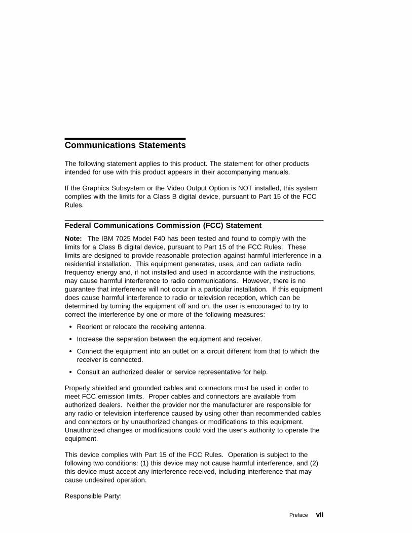
If the Graphics Subsystem or the Video Output Option is NOT installed, this systemcomplies with the limits for a Class B digital device, pursuant to Part 15 of the FCCRules.
Federal Communications Commission (FCC) Statement
Note: The IBM 7025 Model F40 has been tested and found to comply with thelimits for a Class B digital device, pursuant to Part 15 of the FCC Rules. Theselimits are designed to provide reasonable protection against harmful interference in aresidential installation. This equipment generates, uses, and can radiate radiofrequency energy and, if not installed and used in accordance with the instructions,may cause harmful interference to radio communications. However, there is noguarantee that interference will not occur in a particular installation. If this equipmentdoes cause harmful interference to radio or television reception, which can bedetermined by turning the equipment off and on, the user is encouraged to try tocorrect the interference by one or more of the following measures:
� Reorient or relocate the receiving antenna.
� Increase the separation between the equipment and receiver.
� Connect the equipment into an outlet on a circuit different from that to which thereceiver is connected.
� Consult an authorized dealer or service representative for help.
Properly shielded and grounded cables and connectors must be used in order tomeet FCC emission limits. Proper cables and connectors are available fromauthorized dealers. Neither the provider nor the manufacturer are responsible forany radio or television interference caused by using other than recommended cablesand connectors or by unauthorized changes or modifications to this equipment.Unauthorized changes or modifications could void the user's authority to operate theequipment.
This device complies with Part 15 of the FCC Rules. Operation is subject to thefollowing two conditions: (1) this device may not cause harmful interference, and (2)this device must accept any interference received, including interference that maycause undesired operation.
Responsible Party:
Preface vii

International Business Machines CorporationOld Orchard RoadArmonk, New York 10504Telephone: (919) 543-2193
European Union (EU) Statement
This product is in conformity with the protection requirements of EU Council Directive89/336/EEC on the approximation of the laws of the Member States relating toelectromagnetic compatibility. The manufacturer cannot accept responsibility for anyfailure to satisfy the protection requirements resulting from a non-recommendedmodification of the product, including the fitting of option cards supplied by thirdparties. Consult with your dealer or sales representative for details on your specifichardware.
This product has been tested and found to comply with the limits for Class BInformation Technology Equipment according to CISPR 22 / European Standard EN55022. The limits for Class B equipment were derived for typical residentialenvironments to provide reasonable protection against interference with licensedcommunication devices.
International Electrotechnical Commission (IEC) Statement
This product has been designed and built to comply with IEC Standard 950.
United Kingdom Telecommunications Safety Requirements
This equipment is manufactured to the International Safety Standard EN60950 andas such is approved in the UK under the General Approval NumberNS/G/1234/J/100003 for indirect connection to the public telecommunication network.
The network adapter interfaces housed within this equipment are approvedseparately, each one having its own independent approval number. These interfaceadapters, supplied by the manufacturer, do not use or contain excessive voltages.An excessive voltage is one which exceeds 70.7 V peak ac or 120 V dc. Theyinterface with this equipment using Safe Extra Low Voltages only. In order tomaintain the separate (independent) approval of the manufacturer's adapters, it isessential that other optional cards, not supplied by the manufacturer, do not usemain voltages or any other excessive voltages. Seek advice from a competentengineer before installing other adapters not supplied by the manufacturer.
viii Service Guide
Avis de conformité aux normes du ministère des Communications duCanada
Cet appareil numérique de la classe B respecte toutes les exigences du Réglementsur le matériel brouilleur du Canada.
Canadian Department of Communications Compliance Statement
This Class B digital apparatus meets the requirements of the CanadianInterference-Causing Equipment Regulations.
VCCI Statement
The following is a summary of the VCCI Japanese statement in the box above.
This equipment is in the Class 2 category (information equipment to be used in aresidential area or an adjacent area thereto) and conforms to the standards set bythe Voluntary Control Council For Interference by Data Processing Equipment andElectronic Office Machines aimed at preventing radio interference in such residentialarea.
When used near a radio or TV receiver, it may become the cause of radiointerference.
Read the instructions for correct handling.
Preface ix
Radio Protection for Germany
Dieses Gerät ist berechtigt in Übereinstimmung mit dem deutschen EMVG vom9.Nov.92 das EG–Konformitätszeichen zu führen.
Der Aussteller der Konformitätserklärung ist die IBM Germany.
Dieses Gerät erfüllt die Bedingungen der EN 55022 Klasse B.
x Service Guide

If the Graphics Subsystem (Feature Code 7252 or 7253) or the Video Output Option(Feature Code 7254) IS installed, this system complies with the limits for a Class Adigital device, pursuant to Part 15 of the FCC Rules.
Federal Communications Commission (FCC) Statement
Note: This equipment has been tested and found to comply with the limits for aClass A digital device, pursuant to Part 15 of the FCC Rules. These limits aredesigned to provide reasonable protection against harmful interference when theequipment is operated in a commercial environment. This equipment generates,uses, and can radiate radio frequency energy and, if not installed and used inaccordance with the instruction manual, may cause harmful interference to radiocommunications. Operation of this equipment in a residential area is likely to causeharmful interference in which case the user will be required to correct theinterference at his own expense.
Properly shielded and grounded cables and connectors must be used in order tomeet FCC emission limits. Neither the provider nor the manufacturer are responsiblefor any radio or television interference caused by using other than recommendedcables and connectors or by unauthorized changes or modifications to thisequipment. Unauthorized changes or modifications could void the user's authority tooperate the equipment.
This device complies with Part 15 of the FCC Rules. Operation is subject to thefollowing two conditions: (1) this device may not cause harmful interference,and (2)this device must accept any interference received, including interference that maycause undesired operation.
European Union (EU) Statement
This product is in conformity with the protection requirements of EU Council Directive89/336/EEC on the approximation of the laws of the Member States relating toelectromagnetic compatibility. The manufacturer cannot accept responsibility for anyfailure to satisfy the protection requirements resulting from a non-recommendedmodification of the product, including the fitting of option cards supplied by thirdparties. Consult with your dealer or sales representative for details on your specifichardware.
This product has been tested and found to comply with the limits for Class AInformation Technology Equipment according to CISPR 22 / European Standard EN55022. The limits for Class A equipment were derived for commercial and industrialenvironments to provide reasonable protection against interference with licensedcommunication equipment.
Preface xi
Attention: This is a Class A product. In a domestic environment this product maycause radio interference in which case the user may be required to take adequatemeasures.
International Electrotechnical Commission (IEC) Statement
This product has been designed and built to comply with IEC Standard 950.
United Kingdom Telecommunications Safety Requirements
This equipment is manufactured to the International Safety Standard EN60950 andas such is approved in the UK under the General Approval NumberNS/G/1234/J/100003 for indirect connection to the public telecommunication network.
The network adapter interfaces housed within this equipment are approvedseparately, each one having its own independent approval number. These interfaceadapters, supplied by the manufacturer, do not use or contain excessive voltages.An excessive voltage is one which exceeds 70.7 V peak ac or 120 V dc. Theyinterface with this equipment using Safe Extra Low Voltages only. In order tomaintain the separate (independent) approval of the manufacturer's adapters, it isessential that other optional cards, not supplied by the manufacturer, do not usemain voltages or any other excessive voltages. Seek advice from a competentengineer before installing other adapters not supplied by the manufacturer.
Avis de conformité aux normes du ministère des Communications duCanada
Cet appareil numérique de la classe A respecte toutes les exigences du Réglementsur le matériel brouilleur du Canada.
Canadian Department of Communications Compliance Statement
This Class A digital apparatus meets the requirements of the CanadianInterference–Causing Equipment Regulations.
xii Service Guide
VCCI Statement
The following is a summary of the VCCI Japanese statement in the box above.
This equipment is in the Class 1 category (information equipment to be used incommercial and/or industrial areas) and conforms to the standards set by theVoluntary Control Council For Interference by Data Processing Equipment andElectronic Office Machines aimed at preventing radio interference in commercialand/or industrial areas.
Consequently, when used in a residential area or in an adjacent area thereto, radiointerference may be caused to radios and TV receivers, etc.
Read the instructions for correct handling. VCCI-1.
Preface xiii

Radio Protection for Germany
Dieses Gerät ist berechtigt in Übereinstimmung mit dem deutschen EMVG vom9.Nov.92 das EG–Konformitätszeichen zu führen.
Der Aussteller der Konformitätserklärung ist die IBM Germany.
Dieses Gerät erfüllt die Bedingungen der EN 55022 Klasse A. Für diese vonGeräten gilt folgende Bestimmung nach dem EMVG:
Geräte dürfen an Orten, für die sie nicht ausreichend entstört sind, nur mitbesonderer Genehmigung des Bundesministers für Post und Telekommunikationoder des Bundesamtes für Post und Telekommunikation betrieben werden. DieGenehmigung wird erteilt, wenn keine elektromagnetischen Störungen zu erwartensind.
(Auszug aus dem EMVG vom 9.Nov.92, Para.3, Abs.4)
Hinweis
Dieses Genehmigungsverfahren ist von der Deutschen Bundespost noch nichtveröffentlicht worden.
xiv Service Guide
Safety Notices
A danger notice indicates the presence of a hazard that has the potential of causingdeath or serious personal injury.
A caution notice indicates the presence of a hazard that has the potential of causingmoderate or minor personal injury.
Electrical Safety
Observe the following safety instructions any time you are connecting ordisconnecting devices attached to the workstation.
DANGER
An electrical outlet that is not correctly wired could place hazardousvoltage on metal parts of the system or the devices that attach to thesystem. It is the responsibility of the customer to ensure that the outletis correctly wired and grounded to prevent an electrical shock.
Before installing or removing signal cables, ensure that the powercables for the system unit and all attached devices are unplugged.
When adding or removing any additional devices to or from the system,ensure that the power cables for those devices are unplugged beforethe signal cables are connected. If possible, disconnect all powercables from the existing system before you add a device.
Use one hand, when possible, to connect or disconnect signal cablesto prevent a possible shock from touching two surfaces with differentelectrical potentials.
During an electrical storm, do not connect cables for display stations,printers, telephones, or station protectors for communication lines.
CAUTION:This product is equipped with a three–wire power cable and plug for the user'ssafety. Use this power cable with a properly grounded electrical outlet to avoidelectrical shock.
Preface xv

DANGER
To prevent electrical shock hazard, disconnect the power cable fromthe electrical outlet before relocating the system.
xvi Service Guide
Laser Safety Information
The optical drive in this system unit is a laser product. The optical drive has a labelthat identifies its classification. The label, located on the drive, is shown below.
CLASS 1 LASER PRODUCTLASER KLASSE 1LUOKAN 1 LASERLAITEAPPAREIL A LASER DE CLASSE 1
IEC 825:1984 CENELEC EN 60 825:1991
The optical drive in this system unit is certified in the U.S. to conform to therequirements of the Department of Health and Human Services 21 Code of FederalRegulations (DHHS 21 CFR) Subchapter J for Class 1 laser products. Elsewhere,the drive is certified to conform to the requirements of the InternationalElectrotechnical Commission (IEC) 825 (1st edition 1984) and CENELEC EN 60825:1991 for Class 1 laser products.
CAUTION:A class 3 laser is contained in the device. Do not attempt to operate the drivewhile it is disassembled. Do not attempt to open the covers of the drive as itis not serviceable and is to be replaced as a unit.
Class 1 laser products are not considered to be hazardous. The optical drivecontains internally a Class 3B gallium-arsenide laser that is nominally 30 milliwatts at830 nanometers. The design incorporates a combination of enclosures, electronics,and redundant interlocks such that there is no exposure to laser radiation above aClass 1 level during normal operation, user maintenance, or servicing conditions.
Preface xvii

xviii Service Guide
About This Book
This book provides maintenance information that is specific to the system unit,adapters, and attached devices that do not have their own service information. It alsocontains Maintenance Analysis Procedures (MAPs) that are not common to othersystems.
MAPs that are common to all systems are contained in the RS/6000 DiagnosticInformation for Multiple Bus Systems.
This book is used by the service technician to repair system failures. This bookassumes that the service technician has had training on the system unit.
ISO 9000
ISO 9000 registered quality systems were used in the development andmanufacturing of this product.
Related Publications
The following publications are available for purchase:
� The IBM RS/6000 7025 F40 Series User's Guide contains information to helpusers set up, install options, configure, modify, and solve minor problems.
� The RS/6000 Diagnostic Information for Multiple Bus Systems contains commondiagnostic procedures, error codes, service request numbers, and failing functioncodes. This manual is intended for trained service technicians.
� The RS/6000 Adapter, Device, and Cable Information for Multiple Bus Systemscontains information about adapters, external devices, and cabling. This manualis intended to supplement information found in the RS/6000 DiagnosticInformation for Multiple Bus Systems.
� The Site and Hardware Planning Information contains information to help youplan your installation.
Preface xix

xx Service Guide
Chapter 1. Reference Information
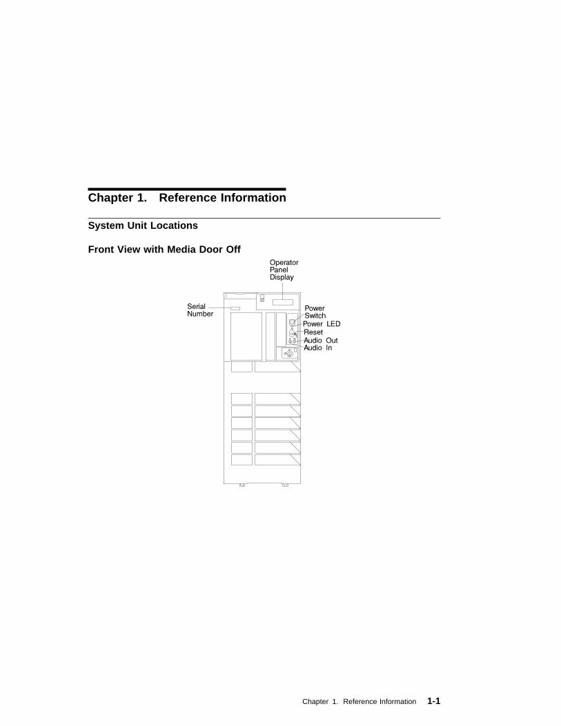
System Unit Locations
Front View with Media Door Off
Chapter 1. Reference Information 1-1
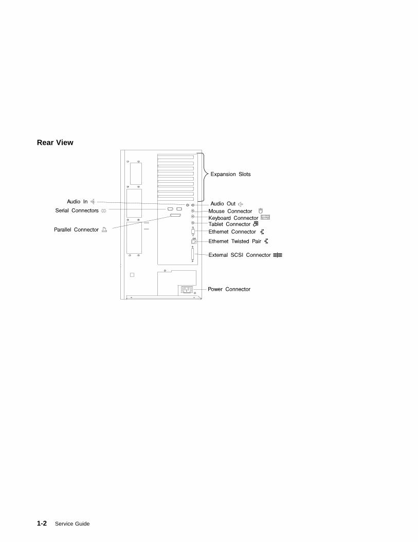
Rear View
1-2 Service Guide
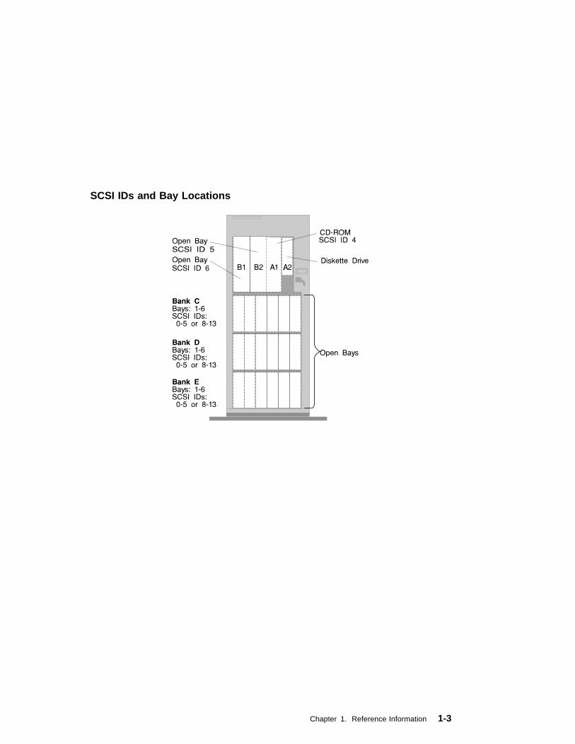
SCSI IDs and Bay Locations
Chapter 1. Reference Information 1-3
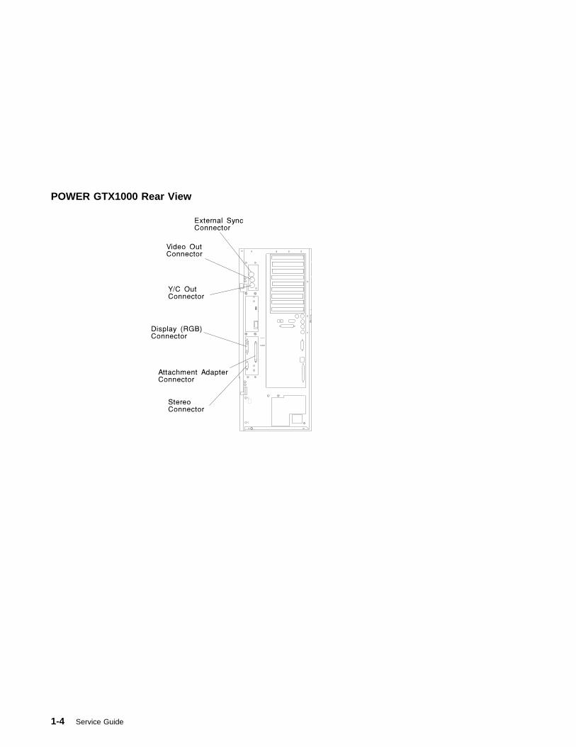
POWER GTX1000 Rear View
1-4 Service Guide

Logic Boards
GPSS Board
Chapter 1. Reference Information 1-5

RSS Board
1-6 Service Guide
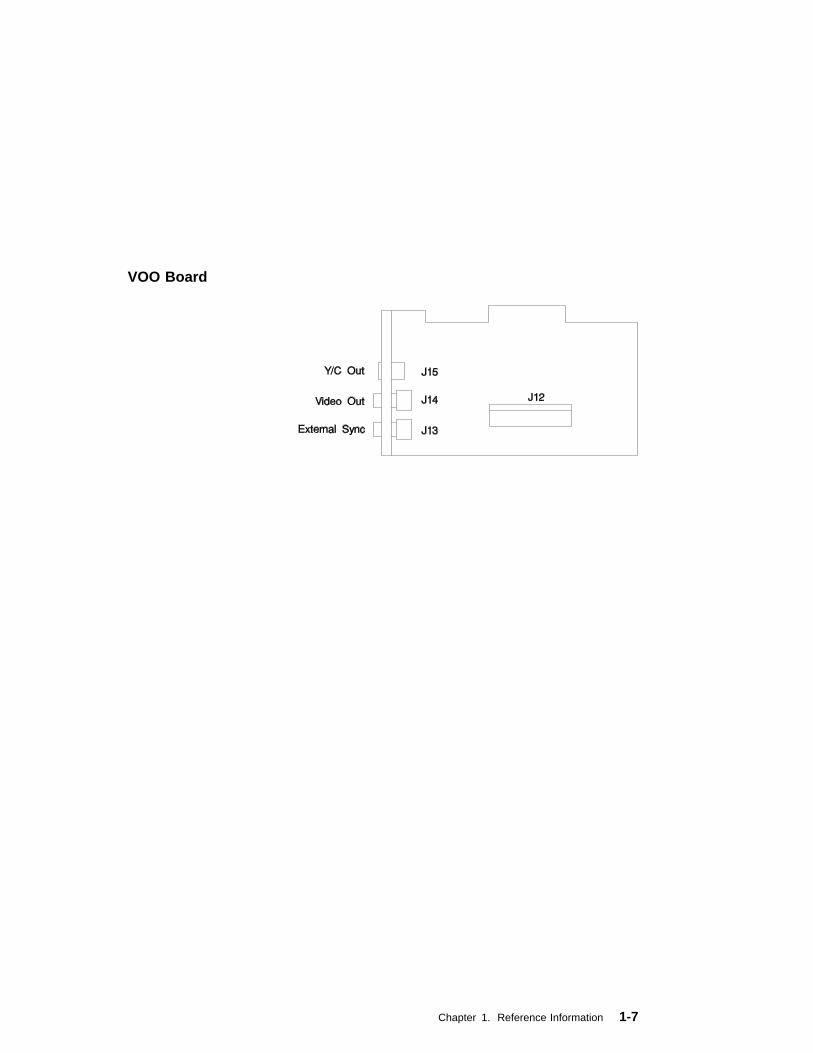
VOO Board
Chapter 1. Reference Information 1-7
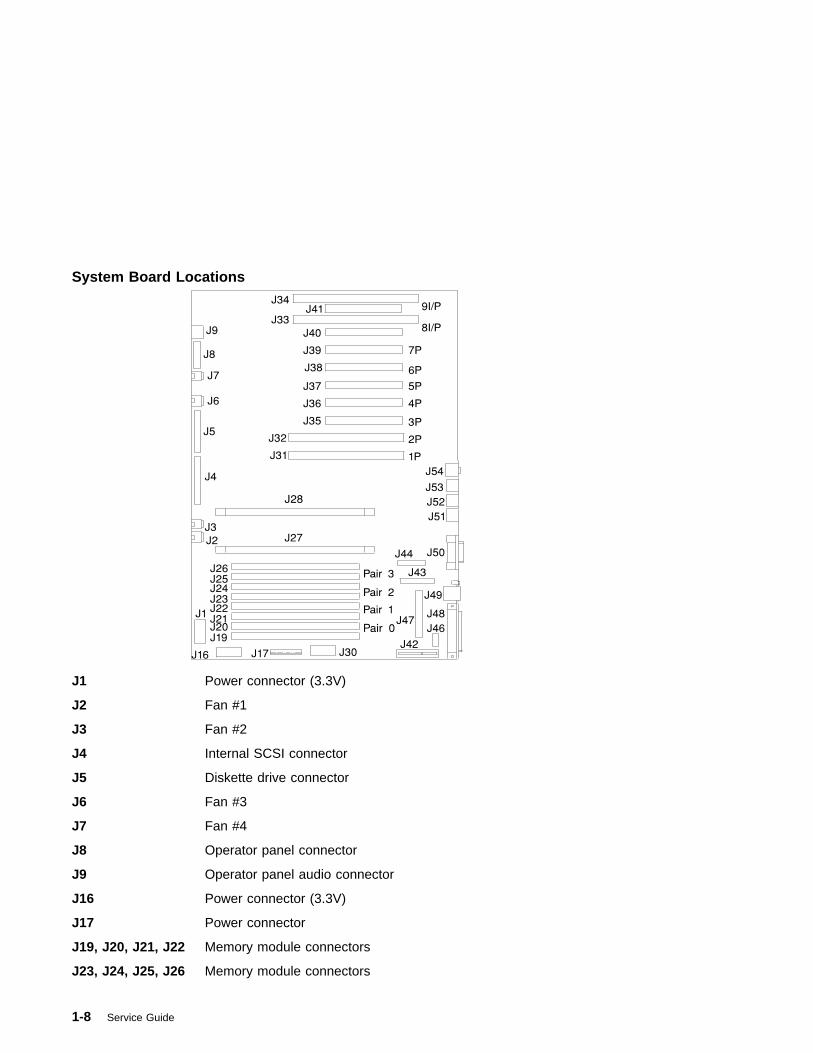
System Board Locations
J1 Power connector (3.3V)
J2 Fan #1
J3 Fan #2
J4 Internal SCSI connector
J5 Diskette drive connector
J6 Fan #3
J7 Fan #4
J8 Operator panel connector
J9 Operator panel audio connector
J16 Power connector (3.3V)
J17 Power connector
J19, J20, J21, J22 Memory module connectors
J23, J24, J25, J26 Memory module connectors
1-8 Service Guide

J27 CPU #0 connector
J28 CPU #1 connector
J30 Power connector (5.0V)
J31, J32 64-bit PCI connectors
J33, J34 ISA connectors
J35, J36, J37, J38 32-bit PCI connectors
J39, J40, J41 32-bit PCI connectors
J42 Service processor connector
J43 Parallel connector
J44 Serial connector
J46 SCSI security jumpers
J47 Internal SCSI connector
J48 External SCSI connector
J49 Ethernet connector (twisted pair)
J50 Ethernet connector (thick)
J51 Tablet connector
J52 Keyboard connector
J53 Mouse connector
J54 Audio connectors
Chapter 1. Reference Information 1-9

Operator Panel
1-10 Service Guide
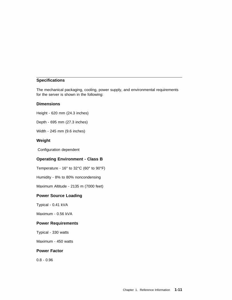
Specifications
The mechanical packaging, cooling, power supply, and environmental requirementsfor the server is shown in the following:
Dimensions
Height - 620 mm (24.3 inches)
Depth - 695 mm (27.3 inches)
Width - 245 mm (9.6 inches)
Weight
Configuration dependent
Operating Environment - Class B
Temperature - 16° to 32°C (60° to 90°F)
Humidity - 8% to 80% noncondensing
Maximum Altitude - 2135 m (7000 feet)
Power Source Loading
Typical - 0.41 kVA
Maximum - 0.56 kVA
Power Requirements
Typical - 330 watts
Maximum - 450 watts
Power Factor
0.8 - 0.96
Chapter 1. Reference Information 1-11

Operating Voltage
100 to 127V ac; 50 to 60 Hz
200 to 240V ac; 50 to 60 Hz
Heat Output (Maximum)
Typical - 1125 BTU/hr
Maximum - 1535 BTU/hr
Acoustics
5.8 Bels operating
5.5 Bels idle
1-12 Service Guide

Power Cables
To avoid electrical shock, a power cable with a grounded attachment plug isprovided. Use only properly grounded outlets.
Power cables used in the United States and Canada are listed by Underwriter'sLaboratories (UL) and certified by the Canadian Standards Association (CSA).These power cords consist of:
� Electrical cables, Type SVT or SJT.
� Attachment plugs complying with National Electrical Manufacturers Association(NEMA) 5-15P. That is:
"For 115 V operation, use a UL listed cable set consisting of a minimum 18 AWG,Type SVT or SJT three-conductor cord a maximum of 15 feet in length and a parallelblade, grounding type attachment plug rated at 15 A, 125 V."
"For 230 V operation in the United States use a UL listed cable set consisting of aminimum 18 AWG, Type SVT or SJT three-conductor cable a maximum of 15 feet inlength, and a tandem blade, grounding type attachment plug rated at 15 A, 250 V."
� Appliance couplers complying with International Electrotechnical Commission(IEC) Standard 320, Sheet C13.
Power cables used in other countries consist of the following:
� Electrical cables, Type HD21.
� Attachment plugs approved by the appropriate testing organization for thespecific countries where they are used.
"For units set at 230 V (outside of U.S.): use a cable set consisting of a minimum 18AWG cable and grounding type attachment plug rated 15 A, 250 V. The cable setshould have the appropriate safety approvals for the country in which the equipmentwill be installed and should be marked HAR'."
Refer to Chapter 8, “ Parts Information” on page 8-1 to find the power cables thatare available.
Chapter 1. Reference Information 1-13
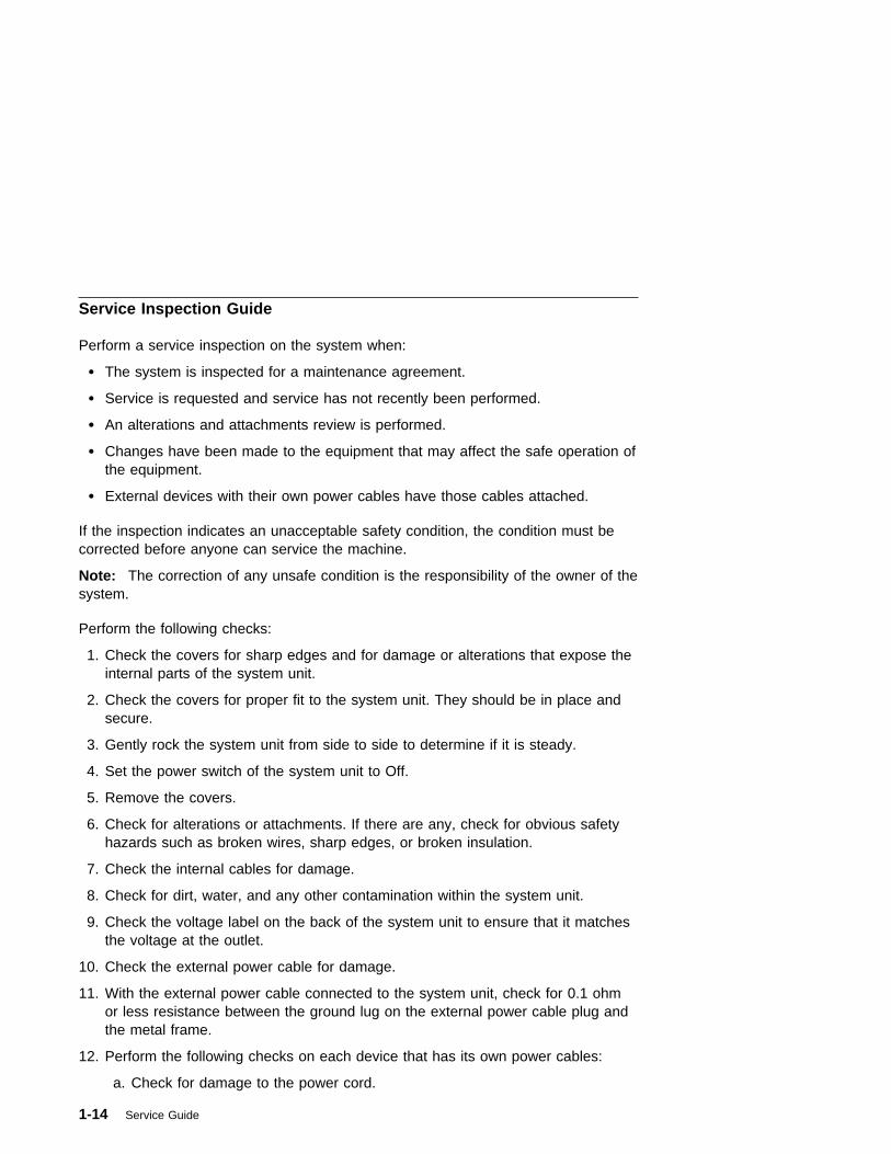
Service Inspection Guide
Perform a service inspection on the system when:
� The system is inspected for a maintenance agreement.
� Service is requested and service has not recently been performed.
� An alterations and attachments review is performed.
� Changes have been made to the equipment that may affect the safe operation ofthe equipment.
� External devices with their own power cables have those cables attached.
If the inspection indicates an unacceptable safety condition, the condition must becorrected before anyone can service the machine.
Note: The correction of any unsafe condition is the responsibility of the owner of thesystem.
Perform the following checks:
1. Check the covers for sharp edges and for damage or alterations that expose theinternal parts of the system unit.
2. Check the covers for proper fit to the system unit. They should be in place andsecure.
3. Gently rock the system unit from side to side to determine if it is steady.
4. Set the power switch of the system unit to Off.
5. Remove the covers.
6. Check for alterations or attachments. If there are any, check for obvious safetyhazards such as broken wires, sharp edges, or broken insulation.
7. Check the internal cables for damage.
8. Check for dirt, water, and any other contamination within the system unit.
9. Check the voltage label on the back of the system unit to ensure that it matchesthe voltage at the outlet.
10. Check the external power cable for damage.
11. With the external power cable connected to the system unit, check for 0.1 ohmor less resistance between the ground lug on the external power cable plug andthe metal frame.
12. Perform the following checks on each device that has its own power cables:
a. Check for damage to the power cord.
1-14 Service Guide
b. Check for the correct grounded power cable.
c. With the external power cable connected to the device, check for 0.1 ohm orless resistance between the ground lug on the external power cable themetal frame of the device.
13. Install the covers.
Chapter 1. Reference Information 1-15

1-16 Service Guide

Chapter 2. System Unit Maintenance Analysis Procedures(MAPs)
Entry MAP
Use the following table to determine your starting point.
Notes:
1. If more than eight digits are displayed in the operator panel, use only the firsteight digits to find the error in the tables. The digits that display beyond the firsteight digits are location codes that can assist you in diagnosing the problem. See“Firmware Location Codes” on page 4-25.
2. Licensed programs frequently rely on network configuration, and systeminformation stored on the VPD on the operator panel control assembly. If theMAPs indicate that the Operator Panel Control Assembly should be replaced,swap the VPD from the old operator panel control assembly to the new one. Ifthe old VPD module has to be replaced call technical support for recoveryinstructions. If recovery is not possible, notify the system owner that new keysfor licensed programs may be required.
3. If a network adapter or the system board is replaced, the network administratormust be notified so that the client IP addresses used by the server can bechanged. In addition, the operating system configuration of the networkcontroller may need to be changed in order to enable system startup.
Symptom Action
Service Actions
You have parts to exchange or a correctiveaction to perform.
1. Go to the Removal and ReplacementProcedures.
2. Go to the Repair Checkout Procedure in theRS/6000 Diagnostic Information for MultipleBus Systems.
You need to verify that a part exchange orcorrective action corrected the problem.
Go to the Repair Checkout Procedure in theRS/6000 Diagnostic Information for Multiple BusSystems.
You need to verify correct system operation. Go to the System Checkout Procedure in theRS/6000 Diagnostic Information for Multiple BusSystems.
Symptom Analysis
You do not have a determined symptom. Go to “MAP 1020: Problem Determination” onpage 2-5.
Chapter 2. Maintenance Analysis Procedures 2-1

Symptom Action
You have an 8-digit error code displayed. Record the error code. Go to Chapter 4, “ErrorCode to FRU Index” on page 4-1.
You have an SRN. Go to the Fast Path MAP in the RS/6000Diagnostic Information for Multiple Bus Systems.
The system POST indicators are displayed onthe system console, the system pauses andthen restarts. The term "POST indicators" referto the icons (graphic display) or devicemnemonics (ASCII terminal) that appear duringthe power-on self-test (POST).
Go to “Fxx Code Boot Problems” on page 4-22.
The system stops and POST indicators aredisplayed on the system console. The term"POST indicators" refer to the icons (graphicdisplay) or device mnemonics (ASCII terminal)that appear during the power-on self-test(POST).
1. Use MAP 1540 to isolate the problem.
The system stops and the message "STARTINGSOFTWARE PLEASE WAIT..." is displayed on
ASCII terminal, the boot indicator ( ) isdisplayed on a graphics terminal.
Go to “Firmware Checkpoints” on page 4-19.
The system will not respond to the passwordbeing entered or the system login prompt isdisplayed when booting in service mode.
Verify that the password is being entered fromthe ASCII terminal or keyboard defined as thesystem console. If so, then the keyboard or itscontroller may be faulty.
1. If entering the password from the keyboardwhich is attached to the system, replace thekeyboard. If replacing the keyboard does notfix the problem, replace the system board.(See notes on 2-1.)
2. If entering the password from a keyboardwhich is attached to a ASCII terminal,suspect the ASCII terminal. Use theProblem Determination Procedures for theterminal. Replace the system board if theseprocedures do not reveal a problem.
Nothing is displayed on the system console, andthe operator panel is blank.
1. If using a graphic display, go to the ProblemDetermination Procedures for the display.
2. If you do not find a problem then replace thedisplay adapter.
3. Go to “MAP 1540: Minimum Configuration”on page 2-14.
2-2 Service Guide

Symptom Action
All display problems. 1. If using a graphics display, go to theProblem Determination Procedures for thedisplay.
2. If you do not find a problem then replace thedisplay adapter.
3. If the problem is with the ASCII terminal:
a. Make sure that the ASCII terminal isconnected to S1.
b. If problems persist, go to the ProblemDetermination Procedures for theterminal.
4. If you do not find a problem then suspectthe system board. Go to “MAP 1540:Minimum Configuration” on page 2-14.
A flashing 888 is displayed in the control panelfollowed by a additional error codes.
Go to the Fast Path MAP in the RS/6000Diagnostic Information for Multiple Bus Systems.
The system stops and a 3-digit number isdisplayed in the operator panel display.
If the number displayed begins with thecharacter "A" or "F" then go to “FirmwareCheckpoints” on page 4-19.
For all other numbers record SRN 101-xxx,where xxx is the three-digit number displayed inthe operator panel, then go to the Fast PathMAP in the RS/6000 Diagnostic Information forMultiple Bus Systems.
The power light does not come on, or stay on. Go to “MAP 1520: Power” on page 2-9.
No codes are displayed on the operator panelwithin a few seconds of turning on the system.
Reseat the operator panel cable.
If problem not resolved, replace in order:
1. Operator panel display.
2. Operator panel control assembly.
3. System board (See notes on 2-1.)
Chapter 2. Maintenance Analysis Procedures 2-3
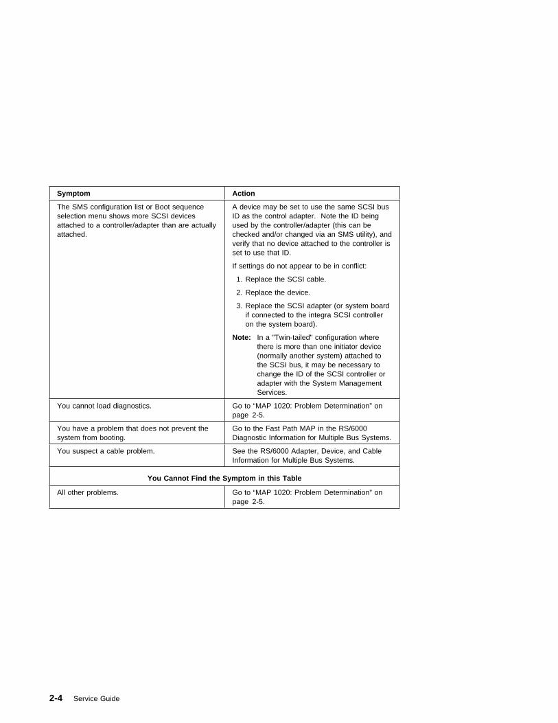
Symptom Action
The SMS configuration list or Boot sequenceselection menu shows more SCSI devicesattached to a controller/adapter than are actuallyattached.
A device may be set to use the same SCSI busID as the control adapter. Note the ID beingused by the controller/adapter (this can bechecked and/or changed via an SMS utility), andverify that no device attached to the controller isset to use that ID.
If settings do not appear to be in conflict:
1. Replace the SCSI cable.
2. Replace the device.
3. Replace the SCSI adapter (or system boardif connected to the integra SCSI controlleron the system board).
Note: In a "Twin-tailed" configuration wherethere is more than one initiator device(normally another system) attached tothe SCSI bus, it may be necessary tochange the ID of the SCSI controller oradapter with the System ManagementServices.
You cannot load diagnostics. Go to “MAP 1020: Problem Determination” onpage 2-5.
You have a problem that does not prevent thesystem from booting.
Go to the Fast Path MAP in the RS/6000Diagnostic Information for Multiple Bus Systems.
You suspect a cable problem. See the RS/6000 Adapter, Device, and CableInformation for Multiple Bus Systems.
You Cannot Find the Symptom in this Table
All other problems. Go to “MAP 1020: Problem Determination” onpage 2-5.
2-4 Service Guide
MAP 1020: Problem Determination
Purpose of This MAP
Use this MAP to get an error code if you were not provided one by the customer oryou are unable to load diagnostics. If you are able to load the diagnostics, go toMAP 0020 in the RS/6000 Diagnostic Information for Multiple Bus Systems.
Be prepared to record code numbers and use those numbers in the course ofanalyzing a problem. Go to “Step 1020-1.”
Step 1020-1
The following steps analyze a failure to load the diagnostic programs.
Note: You are asked questions regarding the operator panel display You are alsoasked to perform certain actions based on displayed POST indicators.Please be observant of these conditions.
1. Insert the diagnostic CD-ROM disc into the CD-ROM drive.
2. Turn the power off.
3. Turn the power on.
4. If the keyboard indicator is displayed (the word keyboard on an ASCII terminalor the keyboard and hand icon on a graphical display), press the F5 key on thedirectly-attached keyboard or the number 5 key on an ASCII terminal.
Chapter 2. Maintenance Analysis Procedures 2-5

5. Enter any requested passwords.
6. Wait until the diagnostics are loaded or the system appears to stop.
7. Find your symptom in the following table; then follow the instructions given in theAction column.
Symptom Action
The diskette LED is blinking rapidly, or FEA orFEB is displayed on the operator panel.
The flash EPROM data is corrupted. Therecovery procedure for the flash EPROM shouldbe executed. See “Firmware Recovery” onpage 6-23.
The system stops with a prompt to enter apassword.
Enter the password. You are not allowed tocontinue until a correct password has beenentered. When you have entered a validpassword go to the beginning of this table andwait for one of the other conditions to occur.
The diagnostics loaded. Go to MAP 0020 in the RS/6000 DiagnosticInformation for Multiple Bus Systems.
The system login prompt is displayed. You may not have pressed the correct key oryou may not have pressed the key soon enoughwhen you were to indicate a Service Mode IPLof the diagnostic programs. If this was the casestart over at the beginning of this Step.
Note: Perform the systems shutdownprocedure before turning off the system.
If you are sure you pressed the correct key in atimely manner, go to “Step 1020-2” onpage 2-7.
The system does not respond when thepassword is entered.
Go to “Step 1020-2” on page 2-7.
The system stopped and a POST indicator isdisplayed on the system console and aneight-digit error code is not displayed.
If the POST indicator represents:
� memory, record error code M0MEM002.
� keyboard, record error code M0KBD000.
� SCSI, record error code M0CON000.
� network, record error code M0NET000.
� speaker (audio), record error codeM0BT0000.
Go to “Step 1020-3” on page 2-7.
All other symptoms. If you were directed here from the Entry MAP,go to “MAP 1540: Minimum Configuration” onpage 2-14. Otherwise, find the symptom in the“Entry MAP” on page 2-1.
2-6 Service Guide

Step 1020-2
There is a problem with the keyboard.
Find the type of keyboard you are using in the following table; then follow theinstructions given in the Action column.
Step 1020-3
Take the following actions:
1. Find the eight-digit error code in Chapter 4, “Error Code to FRU Index” onpage 4-1.
Note: If the eight-digit error code is not listed in Chapter 4, “Error Code to FRUIndex,” look for it in the following:
� Any supplemental service manual for the device
� The diagnostic problem report screen for additional information
� The Service Hints service aid
� The CEREADME file (by using the Service Hints service aid).
2. Perform the action listed.
Keyboard Type Action
Type 101 keyboard (U.S.). Identify by the size ofthe Enter key. The Enter key is in only onehorizontal row of keys.
Record error code M0KBD001; then go to “Step1020-3.”
Type 102 keyboard (W.T.). Identify by the sizeof the Enter key. The Enter key extends into twohorizontal rows.
Record error code M0KBD002; then go to “Step1020-3.”
Type 106 keyboard. (Identify by the Japanesecharacters.)
Record error code M0KBD003; then go to “Step1020-3.”
ASCII terminal keyboard Go to the documentation for this type of ASCIIterminal and continue problem determination.
Chapter 2. Maintenance Analysis Procedures 2-7
Step 1020-4
1. Turn off, then turn on the system unit.
2. When the keyboard indicator appears, press the F1 key on a directly attachedkeyboard or the 1 key on an ASCII terminal. If the keyboard indicator does notappear, go to “MAP 1540: Minimum Configuration” on page 2-14.
3. When the System Management Services appear, check the error log for anyerrors.
� Choose Utilities
� Choose Error Log
� If an error is logged, check the time stamp.
� If the error was logged during the current boot attempt, record it.
� Look up the error in the Chapter 4, “Error Code to FRU Index” on page 4-1and do the listed action.
� If no recent error is logged in the error log, go to “MAP 1540: MinimumConfiguration” on page 2-14.
2-8 Service Guide
MAP 1520: Power
Note: This is not a start of call MAP. Use this Power MAP only if you have beendirected here from a MAP step in the RS/6000 Diagnostic Information for MultipleBus Systems.
This procedure is used to locate power problems in system units. If a problem isdetected, this procedure helps you isolate the problem to a failing unit.
Observe the following safety notice during service procedures.
DANGER
An electrical outlet that is not correctly wired could place hazardousvoltage on metal parts of the system or the devices that attach to thesystem. It is the responsibility of the customer to ensure that the outletis correctly wired and grounded to prevent and electrical shock.
Before installing or removing signal cables, ensure that the powercables for the system unit and all attached devices are unplugged.
When adding or removing any additional devices to or from the system,ensure that the power cables for those devices are unplugged beforethe signal cables are connected. If possible, disconnect all powercables from the existing system before you add a device.
Use on hand, when possible, to connect or disconnect signal cables toprevent a possible shock from touching two surfaces with differentelectrical potentials.
During an electrical storm, do not connect cables for display stations,printers, telephones, or station protectors for communication lines.
CAUTION:This product is equipped with a three–wire power cable and plug for the user'ssafety. Use this power cable with a properly grounded electrical outlet to avoidelectrical shock.
DANGER
To prevent electrical shock hazard, disconnect the power cable fromthe electrical outlet before relocating the system.
Chapter 2. Maintenance Analysis Procedures 2-9
Step 1520-1
You may be directed to this MAP for several reasons:
1. There is no indication of activity when the start/stop switch is pressed. None ofthe LEDs light and none of the fans, including the fan in the power supply, startto turn.
Go to “Step 1520-2.”
2. When the start/stop switch is pressed, the system begins to power on, but thepower LED does not stay on.
Go to “Step 1520-3” on page 2-11.
Step 1520-2
1. Turn the power off.
2. Check that the external power cable to the system unit has continuity.
3. Check that the power outlet has been wired correctly with the correct voltage.
4. Check that the external power cable is plugged into both the system unit and thepower outlet.
Did you find a problem?
NO Go to “Step 1520-3” on page 2-11.
YES Correct the problem. Go to "Map 0410: Repair Checkout" in the RS/6000Diagnostic Information for Multiple Bus Systems.
2-10 Service Guide
Step 1520-3
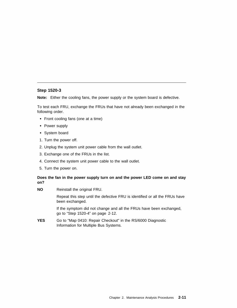
Note: Either the cooling fans, the power supply or the system board is defective.
To test each FRU, exchange the FRUs that have not already been exchanged in thefollowing order.
� Front cooling fans (one at a time)
� Power supply
� System board
1. Turn the power off.
2. Unplug the system unit power cable from the wall outlet.
3. Exchange one of the FRUs in the list.
4. Connect the system unit power cable to the wall outlet.
5. Turn the power on.
Does the fan in the power supply turn on and the power LED come on and stayon?
NO Reinstall the original FRU.
Repeat this step until the defective FRU is identified or all the FRUs havebeen exchanged.
If the symptom did not change and all the FRUs have been exchanged,go to “Step 1520-4” on page 2-12.
YES Go to "Map 0410: Repair Checkout" in the RS/6000 DiagnosticInformation for Multiple Bus Systems.
Chapter 2. Maintenance Analysis Procedures 2-11

Step 1520-4
1. Turn the power off.
2. Unplug the system unit power cable from the wall outlet.
3. Record the slot numbers of all the ISA and PCI adapters. Label and record thelocation of any cables attached to the adapters. Remove all the adapters.
4. Remove all pairs of the memory modules.
5. Remove the CPU card(s).
6. Unplug the power cables from all the SCSI devices.
7. Unplug all the fans, except the fan in the power supply.
8. Connect the system unit power cable to the wall outlet.
9. Turn the power on.
Does the fan in the power supply turn on and the power LED come on and stayon?
NO Replace the system board. Go to "Map 0410: Repair Checkout" in theRS/6000 Diagnostic Information for Multiple Bus Systems
YES Go to “Step 1520-5” on page 2-13.
2-12 Service Guide
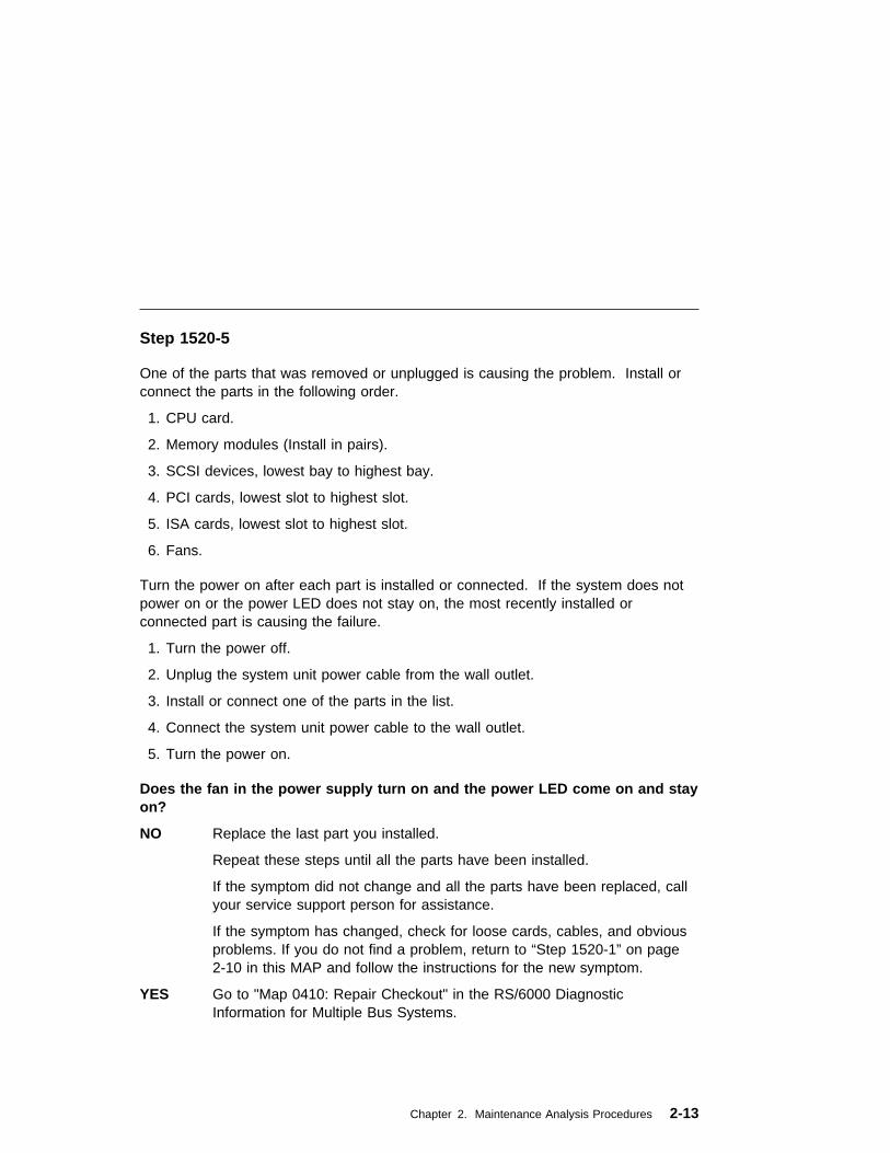
Step 1520-5
One of the parts that was removed or unplugged is causing the problem. Install orconnect the parts in the following order.
1. CPU card.
2. Memory modules (Install in pairs).
3. SCSI devices, lowest bay to highest bay.
4. PCI cards, lowest slot to highest slot.
5. ISA cards, lowest slot to highest slot.
6. Fans.
Turn the power on after each part is installed or connected. If the system does notpower on or the power LED does not stay on, the most recently installed orconnected part is causing the failure.
1. Turn the power off.
2. Unplug the system unit power cable from the wall outlet.
3. Install or connect one of the parts in the list.
4. Connect the system unit power cable to the wall outlet.
5. Turn the power on.
Does the fan in the power supply turn on and the power LED come on and stayon?
NO Replace the last part you installed.
Repeat these steps until all the parts have been installed.
If the symptom did not change and all the parts have been replaced, callyour service support person for assistance.
If the symptom has changed, check for loose cards, cables, and obviousproblems. If you do not find a problem, return to “Step 1520-1” on page2-10 in this MAP and follow the instructions for the new symptom.
YES Go to "Map 0410: Repair Checkout" in the RS/6000 DiagnosticInformation for Multiple Bus Systems.
Chapter 2. Maintenance Analysis Procedures 2-13

MAP 1540: Minimum Configuration
Notes:
1. This MAP assumes that a CD-ROM drive is installed and connected to theintegrated SCSI adapter, and a Diagnostics CD-ROM disc is available.
2. If a power-on password or privileged-access password is installed, you areprompted to enter the password before the diagnostic CD-ROM can load.
3. The term "POST indicators" refer to the icons (graphic display) or devicemnemonics (ASCII terminal) that appear during the power-on self-test (POST).
Purpose of this MAP
This MAP is used to locate defective FRUs not found by normal diagnostics. For thisprocedure, diagnostics are run on a minimally-configured system. If a failure isdetected on the minimally-configured system, the remaining FRUs are exchangedone at a time until the failing FRU is identified. If a failure is not detected, FRUs areadded back until the failure occurs. The failure is then isolated to the failing FRU.
Step 1540-1
1. Ensure that the diagnostics and the operating system are shut down.
2. Insert the diagnostic CD-ROM into the CD-ROM drive.
3. Turn the power off.
4. Turn the power on.
5. When the keyboard indicator is displayed (the word keyboard on an ASCIIterminal or the keyboard and hand icon on a graphical display), press the F5 keyon the directly-attached keyboard or the number 5 key on an ASCII terminal.
6. If the Console Selection screen is displayed, choose the system console.
7. Enter the appropriate password when prompted to do so.
Is the "Please define the System Console" screen displayed?
NO Go to “Step 1540-2” on page 2-15.
YES Go to “Step 1540-12” on page 2-26.
2-14 Service Guide
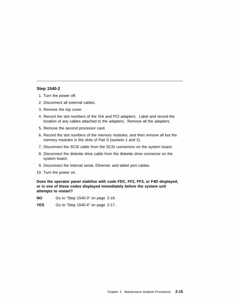
Step 1540-2
1. Turn the power off.
2. Disconnect all external cables.
3. Remove the top cover.
4. Record the slot numbers of the ISA and PCI adapters. Label and record thelocation of any cables attached to the adapters. Remove all the adapters.
5. Remove the second processor card.
6. Record the slot numbers of the memory modules, and then remove all but thememory modules in the slots of Pair 0 (sockets 1 and 2).
7. Disconnect the SCSI cable from the SCSI connectors on the system board.
8. Disconnect the diskette drive cable from the diskette drive connector on thesystem board.
9. Disconnect the internal serial, Ethernet, and tablet port cables.
10. Turn the power on.
Does the operator panel stabilize with code FDC, FF2, FF3, or F4D displayed,or is one of these codes displayed immediately before the system unitattempts to restart?
NO Go to “Step 1540-3” on page 2-16.
YES Go to “Step 1540-4” on page 2-17.
Chapter 2. Maintenance Analysis Procedures 2-15

Step 1540-3
One of the FRUs remaining in the system unit is defective.
If the following steps call for a system board to be replaced, see notes on page 2-1.
1. If F24 is displayed in the operator panel, turn the power off and exchange thefollowing FRUs in order:
a. Memory modules (pair)
b. System board (see notes on page 2-1.)
2. If F24 is NOT displayed in the operator panel, turn the power off and exchangethe following FRUs in order:
a. Processor cards
b. Memory modules (pair)
c. System board (see notes on page 2-1.)
Does the operator panel stabilize with code FDC, FF2, FF3, or F4D displayed,or is one of these codes displayed immediately before the system unitattempts to restart?
NO Reinstall the original FRU.
Repeat the FRU replacement steps until the defective FRU is identified orall the FRUs have been exchanged.
If the symptom did not change and all the FRUs have been exchanged,call your service support person for assistance.
If the symptom has changed, check for loose cards, cables, and obviousproblems. If you do not find a problem, return to “Step 1540-1” on page2-14 in this MAP and follow the instructions for the new symptom.
YES Go to "Map 0410: Repair Checkout" in the RS/6000 DiagnosticInformation for Multiple Bus Systems.
2-16 Service Guide
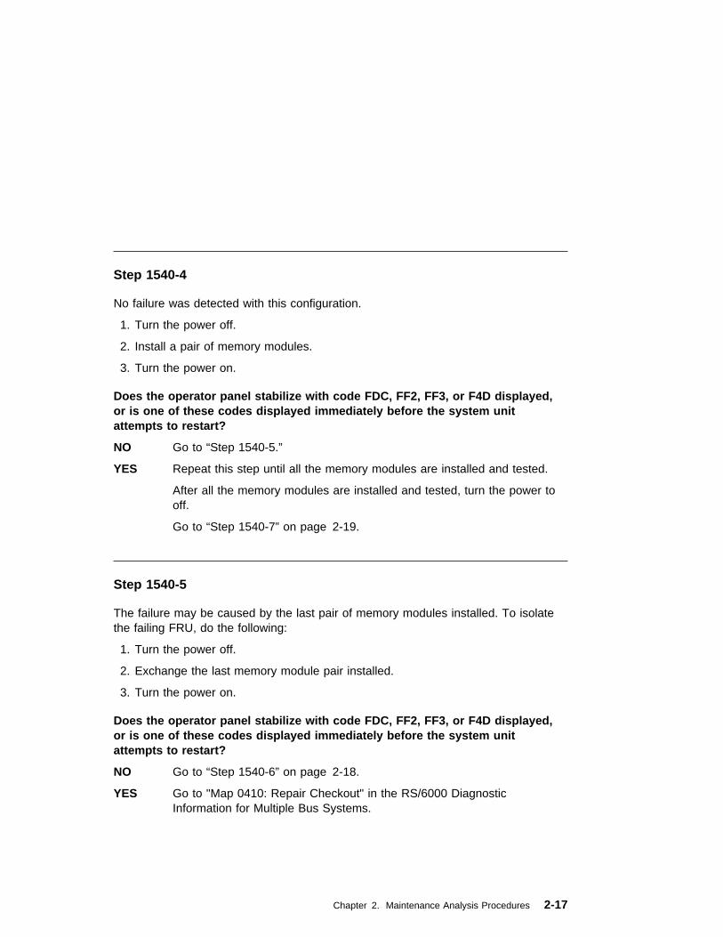
Step 1540-4
No failure was detected with this configuration.
1. Turn the power off.
2. Install a pair of memory modules.
3. Turn the power on.
Does the operator panel stabilize with code FDC, FF2, FF3, or F4D displayed,or is one of these codes displayed immediately before the system unitattempts to restart?
NO Go to “Step 1540-5.”
YES Repeat this step until all the memory modules are installed and tested.
After all the memory modules are installed and tested, turn the power tooff.
Go to “Step 1540-7” on page 2-19.
Step 1540-5
The failure may be caused by the last pair of memory modules installed. To isolatethe failing FRU, do the following:
1. Turn the power off.
2. Exchange the last memory module pair installed.
3. Turn the power on.
Does the operator panel stabilize with code FDC, FF2, FF3, or F4D displayed,or is one of these codes displayed immediately before the system unitattempts to restart?
NO Go to “Step 1540-6” on page 2-18.
YES Go to "Map 0410: Repair Checkout" in the RS/6000 DiagnosticInformation for Multiple Bus Systems.
Chapter 2. Maintenance Analysis Procedures 2-17

Step 1540-6
One of the FRUs remaining in the system unit is defective.
1. Turn the power off.
2. Exchange the following FRUs the order listed.
a. System board (See notes on 2-1.)
b. Power supply.
3. Turn the power on.
Does the operator panel stabilize with code FDC, FF2, FF3, or F4D displayed,or is one of these codes displayed immediately before the system unitattempts to restart?
NO Reinstall the original FRU.
Repeat this step until the defective FRU is identified or all the FRUs havebeen exchanged.
If the symptom did not change and all the FRUs have been exchanged,call your service support person for assistance.
If the symptom has changed, check for loose cards, cables, and obviousproblems. If you do not find a problem, return to “Step 1540-1” onpage 2-14 in this MAP, and follow the instructions for the new symptom.
YES Go to "Map 0410: Repair Checkout" in the RS/6000 DiagnosticInformation for Multiple Bus Systems.
2-18 Service Guide
Step 1540-7
1. Turn the power off.
2. Reconnect the system console.
Notes:
a. If an ASCII terminal has been defined as the system console, attach theASCII terminal cable to the to the S1 connector on the rear of the systemunit. Also connect the internal serial and Ethernet cables to the systemboard.
b. If a display attached to a display adapter has been defined as the systemconsole, install the display adapter and connect the display to it. Plug thekeyboard into the keyboard connector on the rear of the system unit.
3. Turn the power on.
4. If the ASCII terminal or graphics display (including display adapter) areconnected differently than before, the Console Selection screen appears andrequires that a new console be selected.
5. When the keyboard indicator is displayed, press the F1 key on the directlyattached keyboard or the number 1 key on an ASCII terminal. This triggers theSMS.
6. Enter the appropriate password when prompted to do so.
7. Wait until the SMS screen is displayed or the system appears to stop.
Chapter 2. Maintenance Analysis Procedures 2-19

Is the SMS screen displayed?
NO One of the FRUs remaining in the system unit is defective.
In the following order, exchange the FRUs that have not been exchanged:
1. Go to the Problem Determination Procedures (test procedures) for thedevice attached to the S1 serial port or the display attached to thegraphics adapter, and test those devices. If a problem is found,follow the procedures for correcting the problem on that device.
2. Graphics adapter (if installed).
3. Cable (async or graphics, including internal async cable).
4. System board. (see notes on page 2-1.)
Repeat this step until the defective FRU is identified or all the FRUs havebeen exchanged.
If the symptom did not change and all the FRUs have been exchanged,call your service support person for assistance.
If the symptom changed, check for loose cards and obvious problems. Ifyou do not find a problem, return to “Step 1540-1” on page 2-14 andfollow the instructions for the new symptom.
YES Go to “Step 1540-8” on page 2-21.
2-20 Service Guide
Step 1540-8
1. Make sure the diagnostic CD-ROM is inserted into the CD-ROM drive.
2. Turn the power off.
3. Plug the internal SCSI cable into the SCSI connector on the system board.
4. Disconnect the signal and power connectors from all the SCSI devices exceptthe CD-ROM drive.
5. Turn the power on.
6. After the keyboard indicator is displayed, press the F5 key on thedirectly-attached keyboard or the number 5 key on an ASCII terminal keyboard.
7. Enter the appropriate password when prompted to do so.
Chapter 2. Maintenance Analysis Procedures 2-21

Is the "Please define the System Console" screen displayed?
NO One of the FRUs remaining in the system unit is defective.
In the following order, exchange the FRUs that have not been exchanged:
1. SCSI cable
2. Last SCSI device connected (CD-ROM drive, tape drive, etc.)
3. The graphics adapter, if the system console is defined as a graphicaldisplay.
4. System board (see notes on page 2-1.)
5. Processor card
6. Power Supply.
Repeat this step until the defective FRU is identified or all the FRUs havebeen exchanged.
If the symptom did not change and all the FRUs have been exchangedcall your service support person for assistance.
If the symptom has changed, check for loose cards, cables, and obviousproblems. If you do not find a problem, return to “Step 1540-1” onpage 2-14 in this MAP and follow the instructions for the new symptom.
YES Repeat this step, adding one SCSI device at a time, until all the SCSIdevices that were attached to the integrated SCSI adapter are connectedand tested.
Go to “Step 1540-9” on page 2-23.
2-22 Service Guide

Step 1540-9
The system is working correctly with this configuration. One of the FRUs (adapters)that you removed is probably defective.
1. Make sure the diagnostic CD-ROM disc is inserted into the CD-ROM drive.
2. Turn the power off.
3. Plug the diskette drive cable into the diskette drive connector on the systemboard.
4. Turn the power on.
5. After the keyboard indicator is displayed, press the F5 key on thedirectly-attached keyboard or the number 5 key on an ASCII terminal keyboard.
6. Enter the appropriate password when prompted to do so.
Is the "Please define the System Console" screen displayed?
NO One of the FRUs remaining in the system is defective.
In the following order, exchange the FRUs that have not been exchanged.
1. Diskette drive
2. Diskette drive cable
3. System board (see notes on page 2-1).
4. Power supply
Repeat this step until the defective FRU is identified or all the FRUs havebeen exchanged.
If the symptom did not change and all the FRUs have been exchanged,call your service support person for assistance.
If the symptom has changed check for loose cards, cables, and obviousproblems. If you do not find a problem return to “Step 1540-1” onpage 2-14 in this MAP and follow the instructions for the new symptom.
YES Go to “Step 1540-10” on page 2-24.
Chapter 2. Maintenance Analysis Procedures 2-23

Step 1540-10
The system is working correctly with this configuration. One of the FRUs (adapters)that you removed is probably defective,
1. Turn the power off.
2. Install the second CPU card if one was removed. If a second CPU card was notremoved, or has already been reinstalled and verified, install a FRU (adapter)and connect any cables and devices that were attached to it.
3. Turn the power on.
4. If the Console Selection screen displays, choose the system console.
5. After the keyboard indicator displayeds, press the F5 key on the directly-attachedkeyboard or the number 5 key on an ASCII terminal keyboard.
6. Enter the appropriate password when prompted to do so.
Is the "Please define the System Console" screen displayed?
NO Go to “Step 1540-11” on page 2-25.
YES Repeat this step until all of the FRUs (adapters) are installed, then go tothe Repair Checkout Procedure in the RS/6000 Diagnostic Information forMultiple Bus Systems.
2-24 Service Guide

Step 1540-11
The last FRU installed or one of its attached devices is probably defective.
1. Make sure the diagnostic CD-ROM disc is inserted into the CD-ROM drive.
2. Turn the power off.
3. Starting with the last installed adapter, disconnect one attached device andcable.
4. Turn the power on.
5. If the Console Selection screen is displayed, choose the system console.
6. After the keyboard indicator appears, press the F5 key on the directly-attachedkeyboard or the number 5 key on an ASCII terminal keyboard.
7. Enter the appropriate password when prompted to do so.
Is the "Please define the System Console" screen displayed?
NO Repeat this step until the defective device or cable is identified or all thedevices and cables have been disconnected.
If all the devices and cables have been removed, then one of the FRUsremaining in the system unit is defective.
To test each FRU, exchange the FRUs in the following order:
1. Adapter (last one installed)
2. System board
If the system board or a network adapter is replaced, see notes onpage 2-1.
3. Power supply.
If the symptom did not change and all the FRUs have been exchanged,call your service support person for assistance.
If the symptom has changed check for loose cards, cables, and obviousproblems. If you do not find a problem return to “Step 1540-1” onpage 2-14 in this MAP and follow the instructions for the new symptom.
YES The last device or cable that you disconnected is defective.
Exchange the defective device or cable.
Go to "Map 0410: Repair Checkout" in the RS/6000 DiagnosticInformation for Multiple Bus Systems.
Chapter 2. Maintenance Analysis Procedures 2-25

Step 1540-12
1. Follow the instructions on the screen to select the system console.
2. When the DIAGNOSTIC OPERATING INSTRUCTIONS screen is displayed,press Enter.
3. If the terminal type has not been defined, you must use the Initial Terminal optionon the FUNCTION SELECTION menu to initialize the AIX operating systemenvironment before you can continue with the diagnostics. This is a separate anddifferent operation than selecting the console display.
4. Select Advanced Diagnostic Routines.
5. When the DIAGNOSTIC MODE SELECTION menu displays, select SystemVerification.
6. Start with the first item on the list and test all the adapters and devices.
Did you get an SRN?
NO Go to “Step 1540-14” on page 2-27.
YES Go to “Step 1540-13.”
Step 1540-13
Look at the FRU part numbers associated with the SRN.
Have you exchanged all the FRUs that correspond to the failing functioncodes?
NO Exchange the FRU with the highest failure percentage that has not beenchanged.
Repeat this step until all the FRUs associated with the SRN have beenexchanged or diagnostics run with no trouble found. Run diagnostics aftereach FRU is exchanged.
If the system board or a network adapter is replaced, see notes on page2-1.
Go to "Map 0410: Repair Checkout" in the RS/6000 DiagnosticInformation for Multiple Bus Systems.
YES If the symptom did not change and all the FRUs have been exchanged,call your service support person for assistance.
2-26 Service Guide

Step 1540-14
Consult the ISA and PCI adapter configuration documentation for your operatingsystem to verify that all installed adapters are configured correctly.
Go to "MAP 0410: Repair Checkout" in the RS/6000 Diagnostic Information forMultiple Bus Systems.
If the symptom did not change and all the FRUs have been exchanged, call yourservice support person for assistance.
Chapter 2. Maintenance Analysis Procedures 2-27

2-28 Service Guide
Chapter 3. SSA Problem Determination Procedures
Problem determination procedures are provided by power-on self-tests (POSTs),service request numbers (SRNs), and maintenance analysis procedures (MAPs).Some of these procedures use the using system service aids that are described inthe system unit User's Guide.
Disk Drive Module Power-On Self-Tests (POSTs)
Attention: Disk drive modules are fragile. Handle them with care. Follow allESD-sensitive parts procedures when handling disk drive modules. For ESDinformation, see “Handling Static–Sensitive Devices” on page 7-2.
The disk drive module POSTs start each time the module is switched on or when aSend Diagnostic command is received from the SSA adapter. They check whetherthe disk drive module is working correctly. The POSTs also help verify a repair aftera FRU has been exchanged.
There are two power-on self-tests: POST-1 and POST-2.
POST-1 runs immediately after the ‘power-on reset’ line goes inactive, and beforethe disk drive module motor starts. POST-1 includes tests of the:
� Microprocessor � ROM � Safety circuits
If POST-1 completes successfully, POST-2 is enabled.
If POST-1 fails, the disk drive module check light stays on, and the disk drive moduleis not configured into the SSA network.
POST-2 runs after the disk drive module motor has started. POST-2 includes testsof:
� Motor control � Servo control� Read and write on the diagnostic cylinder (repeated for all heads)� Error checking and correction (ECC)
If POST-2 completes successfully, the disk drive module is ready for use by theusing system.
Chapter 3. SSA Problem Determination Procedures 3-1
Adapter Power-On Self-Tests (POSTs)
Two power-on self-tests (POSTs) are resident in the SSA adapter. The tests arePOST-1 and POST-2.
POST-1 tests all the functions that are necessary to enable the adapter tocommunicate with the Micro Channel. POST-1 can fail for either of two reasons:
� A hardware error has been detected. In such instances, the POST code entersa tight loop, and does not put the identification of the SSA adapter into theprogrammable option select (POS) registers. If this error occurs, the SSAadapter must be exchanged for a new one.
� The flash erasable programmable read-only memory (EPROM) has a check sumthat is not valid. This error can be caused if the power fails while microcode isbeing downloaded. In such instances, the POST checks all the hardware that isneeded to download the microcode. If all the hardware is correct, the POST setsthe ROS level to zero, puts the identification of the SSA adapter into POS 0-1,and puts error data into the adapter status register.
To recover from this type of error, microcode must be downloaded to the SSAadapter. If the using system can have an initial program load (IPL) without theadapter, the configuration code detects the down-level ROS code and downloadsthe latest level of code. The configuration code then uses control register bit 7 toreset the adapter and restart POST-1.
If no error is detected during POST-1, the identification of the SSA adapter is put intothe POS registers, and POST-2 is started.
POST-2 tests the remaining hardware on the SSA adapter card and tests the otherFRUs that are attached to the adapter. If this test fails, an error code is saved andsent to the using-system error log when the error logger becomes available. Aninternal health check continues to send the error code at regular intervals.
3-2 Service Guide

Service Request Numbers (SRNs)
Service request numbers (SRNs) are generated for the SSA Hot-Swap Disk Drive bythe system error-log analysis, system configuration code, diagnostics, and customerproblem-determination procedures. SRNs help you to identify the cause of aproblem, the failing field-replaceable units (FRUs), and the service actions that mightbe needed to solve the problem.
The SRN Table
Table 3-1 on page 3-5 lists the SRNs and describes the actions you should perform.The table columns are:
SRN The service reference number
FRU list The FRU or FRUs that might be causing the problem (see also “FRUNames Used in the SRN Table” on page 3-4)
% How likely it is (by percentage) that the FRU is causing the problem
Problem A description of the problem and the action you must take
Abbreviations used in the table are:
DMA Direct memory access
FRU Field-replaceable unit
IOCC Input/output channel controller
POS Programmable option select (POS registers)
POST Power-on self-test
PAA P = adapter port numberAA = SSA address
Using the SRN Table
1. Locate the SRN in the table. If you cannot find the SRN, you have a problemwith the diagnostics, the microcode, or the documentation. Call your supportcenter for assistance.
2. Read carefully the “Action” you must perform for the problem. Do not exchangeFRUs unless you are instructed to do so.
3. Normally exchange only one FRU at a time, starting from the top of the FRU listfor that SRN. Always use instructions given in the page reference whenexchanging FRUs. After each FRU is exchanged, go to "MAP 410: RepairCheckout" in RS/6000 Diagnostic Information for Multiple Bus Systems to verifythe repair.
Chapter 3. SSA Problem Determination Procedures 3-3
Software and Microcode Errors
Some SRNs indicate that a problem might have been caused by a software error orby a microcode error. If you have one of these SRNs, perform the following actions:
1. Make a note of the contents of the error log for the device that has the problem.
2. Go to the using-system service aids and select Display Vital Product Data todisplay the VPD of the failing system. Make a note of the VPD for all the SSAadapters and disk drive modules.
3. Report the problem to your support center. The center can tell you whether youhave a known problem and can, if necessary, provide you with a correction forthe software or microcode.
FRU Names Used in the SRN Table
This section provides a glossary of the FRU names used.
FRU Name in Table Definition
Backplane assembly The disk drive modules, blank disk drive modules, andinternal SSA cables, are connected to the backplaneassembly.
Disk drive module A disk drive assembly to a carrier that plugs into thebackplane in the system unit.
Blank Disk drive module This module must be installed in a slot that does notcontain a disk drive module. This completes the SSAloop through the system unit.
External SSA cable A cable that connects the bulkhead to the SSA adapteror to an SSA subsystem.
Internal SSA cable Attaches the backplane to the SSA adapter card.
SSA adapter card The SSA adapter card, which is located in the usingsystem.
3-4 Service Guide
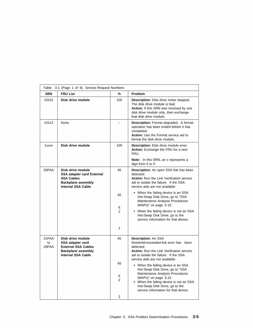
Table 3-1 (Page 1 of 9). Service Request Numbers
SRN FRU List % Problem
10101 Disk drive module 100 Description: Disk drive motor stopped.The disk drive module is bad.Action: If this SRN was received by onedisk drive module only, then exchangethat disk drive module.
10112 None – Description: Format degraded. A formatoperation has been ended before it hascompleted.Action: Use the Format service aid toformat the disk drive module.
1xxxx Disk drive module 100 Description: Disk drive module error.Action: Exchange the FRU for a newFRU.
Note: In this SRN, an x represents adigit from 0 to F.
20PAA Disk drive moduleSSA adapter card ExternalSSA CablesBackplane assemblyInternal SSA Cable
45
45 62 2
Description: An open SSA link has beendetected.Action: Run the Link Verification serviceaid to isolate the failure. If the SSAservice aids are not available:
� When the failing device is an SSAHot-Swap Disk Drive, go to “SSAMaintenance Analysis Procedures(MAPs)” on page 3-15.
� When the failing device is not an SSAHot-Swap Disk Drive, go to theservice information for that device.
21PAAto
29PAA
Disk drive moduleSSA adapter cardExternal SSA CablesBackplane assemblyInternal SSA Cable
45
45 62 2
Description: An SSAthreshold-exceeded-link error has beendetected.Action: Run the Link Verification serviceaid to isolate the failure. If the SSAservice aids are not available:
� When the failing device is an SSAHot-Swap Disk Drive, go to “SSAMaintenance Analysis Procedures(MAPs)” on page 3-15.
� When the failing device is not an SSAHot-Swap Disk Drive, go to theservice information for that device.
Chapter 3. SSA Problem Determination Procedures 3-5
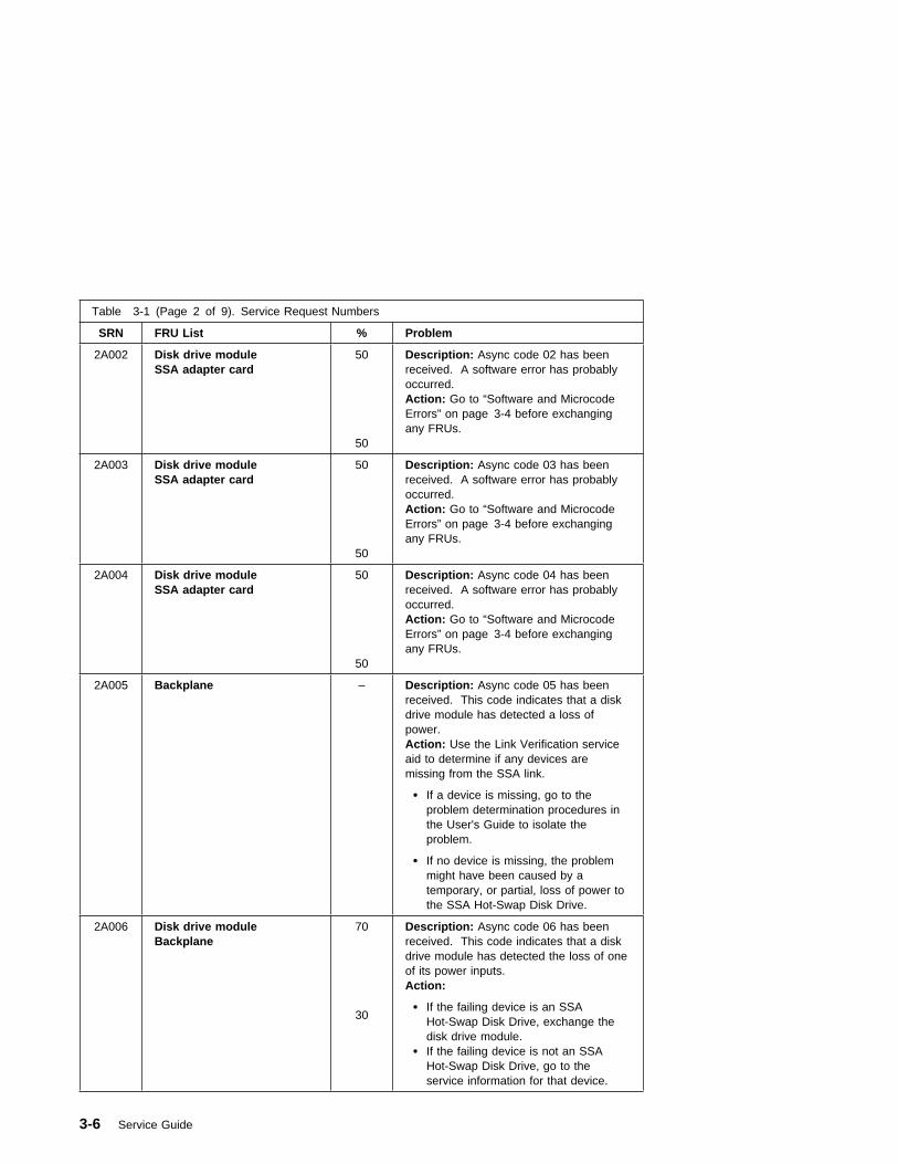
Table 3-1 (Page 2 of 9). Service Request Numbers
SRN FRU List % Problem
2A002 Disk drive moduleSSA adapter card
50
50
Description: Async code 02 has beenreceived. A software error has probablyoccurred.Action: Go to “Software and MicrocodeErrors” on page 3-4 before exchangingany FRUs.
2A003 Disk drive moduleSSA adapter card
50
50
Description: Async code 03 has beenreceived. A software error has probablyoccurred.Action: Go to “Software and MicrocodeErrors” on page 3-4 before exchangingany FRUs.
2A004 Disk drive moduleSSA adapter card
50
50
Description: Async code 04 has beenreceived. A software error has probablyoccurred.Action: Go to “Software and MicrocodeErrors” on page 3-4 before exchangingany FRUs.
2A005 Backplane – Description: Async code 05 has beenreceived. This code indicates that a diskdrive module has detected a loss ofpower.Action: Use the Link Verification serviceaid to determine if any devices aremissing from the SSA link.
� If a device is missing, go to theproblem determination procedures inthe User's Guide to isolate theproblem.
� If no device is missing, the problemmight have been caused by atemporary, or partial, loss of power tothe SSA Hot-Swap Disk Drive.
2A006 Disk drive moduleBackplane
70
30
Description: Async code 06 has beenreceived. This code indicates that a diskdrive module has detected the loss of oneof its power inputs.Action:
� If the failing device is an SSAHot-Swap Disk Drive, exchange thedisk drive module.
� If the failing device is not an SSAHot-Swap Disk Drive, go to theservice information for that device.
3-6 Service Guide

Table 3-1 (Page 3 of 9). Service Request Numbers
SRN FRU List % Problem
2A106 Backplane assembly 100 Description: Async code 06 has beenreceived. This code indicates that multipledisk drive modules have detected the lossof one of its their power inputs.Action:
� If the failing devices are SSAHot-Swap Disk Drives, exchange thebackplane.
� If the failing devices are not SSAHot-Swap Disk Drives, go to theservice information for those devices.
2A206 Disk drive module 100 Description: A disk drive module hasdetected that one of its SSA links hasfailed the POSTs.Action:
1. Use the Link Verification service aid todetermine where the SSA link isbroken.
2. Run diagnostics in the systemverification mode to the two disk drivemodules that are nearest to, and oneach side of, the place where the linkis broken. The diagnostics showwhich disk drive module detected theproblem.
2FFFF None – Description: An async code that is notvalid has been received.Action: Go to “Software and MicrocodeErrors” on page 3-4.
300C0 Backplane 100 Description: A disk drive module hasdetected the loss of one of its powerinputs.Action:
� If the failing device is an SSAHot-Swap Disk Drive, exchange thebackplane.
� If the failing device is not an SSAHot-Swap Disk Drive, go to theservice information for that device.
Chapter 3. SSA Problem Determination Procedures 3-7

Table 3-1 (Page 4 of 9). Service Request Numbers
SRN FRU List % Problem
301C0 Backplane assembly 100 Description: Multiple disk drive moduleshave detected the loss of one of theirpower inputs.Action:
� If the failing devices are SSAHot-Swap Disk Drives, exchange thebackplane.
� If the failing devices are not SSAHot-Swap Disk Drives, go to theservice information for those devices.
303FF Disk drive module 100 Description: An SCSI status that is notvalid has been received.Action: Go to “Software and MicrocodeErrors” on page 3-4 before exchangingany FRUs.
40000 SSA adapter card 100 Description: The SSA adapter card hasfailed.Action: Exchange the FRU for a newFRU.
43PAA Disk drive moduleSSA adapter card
90
10
Description: An SSA device on the link ispreventing the completion of the linkconfiguration.Action: If the SSA service aids areavailable, run the Link Verification serviceaid to determine which device ispreventing configuration. (That device isthe one beyond the last-configured deviceon an open SSA link.)
44PAA Disk drive module 100 Description: A disk drive module hasfailed.Action: If the SSA service aids areavailable, run the Link Verification serviceaid to find the failing disk drive module.Before you exchange the failing disk drivemodule, run diagnostics in the systemverification mode to the module todetermine the cause of the problem.
3-8 Service Guide

Table 3-1 (Page 5 of 9). Service Request Numbers
SRN FRU List % Problem
45PAA Disk drive module ExternalSSA Cables Backplaneassembly
40
4020
Description: The SSA adapter hasdetected an open SSA link. This problemis caused either by a disk drive modulethat is failing, or by a disk drive modulethat has been switched off from anotherusing system on the same SSA link.(That using system has itself beenswitched off.)Action: If the SSA service aids areavailable, run the Link Verification serviceaid to determine which device ispreventing configuration. (That device isthe one beyond the last-configured deviceon an open SSA link.)
48000 None – Description: The SSA adapter hasdetected a link configuration resource thatis not valid.Action: See “SSA Loop ConfigurationsThat Are Not Valid” on page 3-14.
50000 SSA adapter card 100 Description: The SSA adapter failed torespond to the device driver.Action: Exchange the FRU for a newFRU.
50001 SSA adapter card 100 Description: A data parity error hasoccurred.Action: Exchange the FRU for a newFRU.
50002 SSA adapter card 100 Description: An SSA adapter directmemory access (DMA) error has occurred.Action: Exchange the FRU for a newFRU.
50004 SSA adapter card 100 Description: A channel check hasoccurred.Action: Exchange the FRU for a newFRU.
50005 SSA adapter card 100 Description: A software error hasoccurred.Action: Go to “Software and MicrocodeErrors” on page 3-4 before exchangingthe FRU.
50006 SSA adapter card 100 Description: A channel check hasoccurred.Action: Exchange the FRU for a newFRU.
Chapter 3. SSA Problem Determination Procedures 3-9
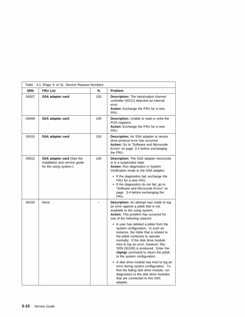
Table 3-1 (Page 6 of 9). Service Request Numbers
SRN FRU List % Problem
50007 SSA adapter card 100 Description: The input/output channelcontroller (IOCC) detected an internalerror.Action: Exchange the FRU for a newFRU.
50008 SSA adapter card 100 Description: Unable to read or write thePOS registers.Action: Exchange the FRU for a newFRU.
50010 SSA adapter card 100 Description: An SSA adapter or devicedrive protocol error has occurred.Action: Go to “Software and MicrocodeErrors” on page 3-4 before exchangingthe FRU.
50012 SSA adapter card (See theinstallation and service guidefor the using system.)
100 Description: The SSA adapter microcodeis in a suspended state.Action: Run diagnostics in SystemVerification mode to the SSA adapter.
� If the diagnostics fail, exchange theFRU for a new FRU.
� If the diagnostics do not fail, go to“Software and Microcode Errors” onpage 3-4 before exchanging theFRU.
50100 None – Description: An attempt was made to logan error against a pdisk that is notavailable to the using system.Action: This problem has occurred forone of the following reasons:
� A user has deleted a pdisk from thesystem configuration. In such aninstance, the hdisk that is related tothe pdisk continues to operatenormally. If the disk drive moduletries to log an error, however, thisSRN (50100) is produced. Enter thecfgmgr command to return the pdiskto the system configuration.
� A disk drive module has tried to log anerror during system configuration. Tofind the failing disk drive module, rundiagnostics to the disk drive modulesthat are connected to this SSAadapter.
3-10 Service Guide

Table 3-1 (Page 7 of 9). Service Request Numbers
SRN FRU List % Problem
60000 SSA adapter card 100 Description: The SSA adapter is missingfrom the expected configuration.Action: Verify that the SSA adapter cardis installed in the expected slot of theusing-system.
� If it is in the expected slot, exchangethe FRU for a new FRU.
� If it is not in the expected slot, enterthe diag -a command, and answer thequestions that are displayed.
7xxxx Disk drive moduleBackplane assembly
80
Description: An SSA Hot-Swap DiskDrive module is missing from the expectedconfiguration of the SSA loop.Action: Replace the FRUs one at a time.Go to "MAP 410: Repair Checkout" inRS/6000 Diagnostic Information forMultiple Bus Systems to verify eachrepair.
D0000 Disk drive module 100 Description: The using system cannotconfigure the disk drive module. This isprobably a software problem.Action:
1. Try again to configure the disk drivemodule.
2. If the problem remains, go to“Software and Microcode Errors” onpage 3-4 before exchanging the FRU.
D0100 Disk drive module 100 Description: Unable to clear a disk drivemodule reservation.Action: Exchange the FRU for a newFRU.
D0101 Disk drive module 100 Description: The disk drive module hasbeen reserved since the diagnosticsstarted. The disk drive module is in use.Action: Release the disk drive module,and run the diagnostics again.
D0200 Disk drive module 100 Description: The disk drive module timedout while the diagnostics were running.Action: Rerun the diagnostics. If theproblem remains, exchange the FRU for anew FRU.
D0300 Disk drive module 100 Description: The disk drive module failedthe diagnostic test.Action: Exchange the FRU for a newFRU.
Chapter 3. SSA Problem Determination Procedures 3-11

Table 3-1 (Page 8 of 9). Service Request Numbers
SRN FRU List % Problem
D0400 Disk drive module 100 Description: The disk drive module is notready while the diagnostics are running.Action: Rerun the diagnostics. If theproblem remains, exchange the FRU for anew FRU.
D0450 None – Description: A format operation is inprogress. The format operation that wasstarted on this disk drive module has notyet finished. A format operation can takeup to 30 minutes to run.Action: Wait for the format operation tofinish before you run the diagnosticsagain. You can observe the progress ofthe Format operation by running theFormat service aid again on this disk drivemodule.
D0460 None – Description: A format operation has beendegraded. The format operation that wasstarted on this disk drive module did notfinish. Possibly, the disk drive modulewas switched off while the formatoperation was running.Action: Run the Format service aid toformat this disk drive module.
D4000 SSA adapter card 100 Description: The diagnostics cannotconfigure the SSA adapter.Action: Exchange the FRU for a newFRU.
D4100 SSA adapter card 100 Description: The diagnostics cannot openthe SSA adapter.Action: Exchange the FRU for a newFRU.
D4300 SSA adapter card 100 Description: The diagnostics havedetected an SSA adapter POST failure.Action: Exchange the FRU for a newFRU.
D44xx SSA adapter card 100 Description: The diagnostics havedetected that the SSA adapter hascorrupted the microcode, but cannotdownload a new version of the microcode.Action: Exchange the FRU for a newFRU.
Note: In this SRN, an x represents adigit 0 through F.
3-12 Service Guide
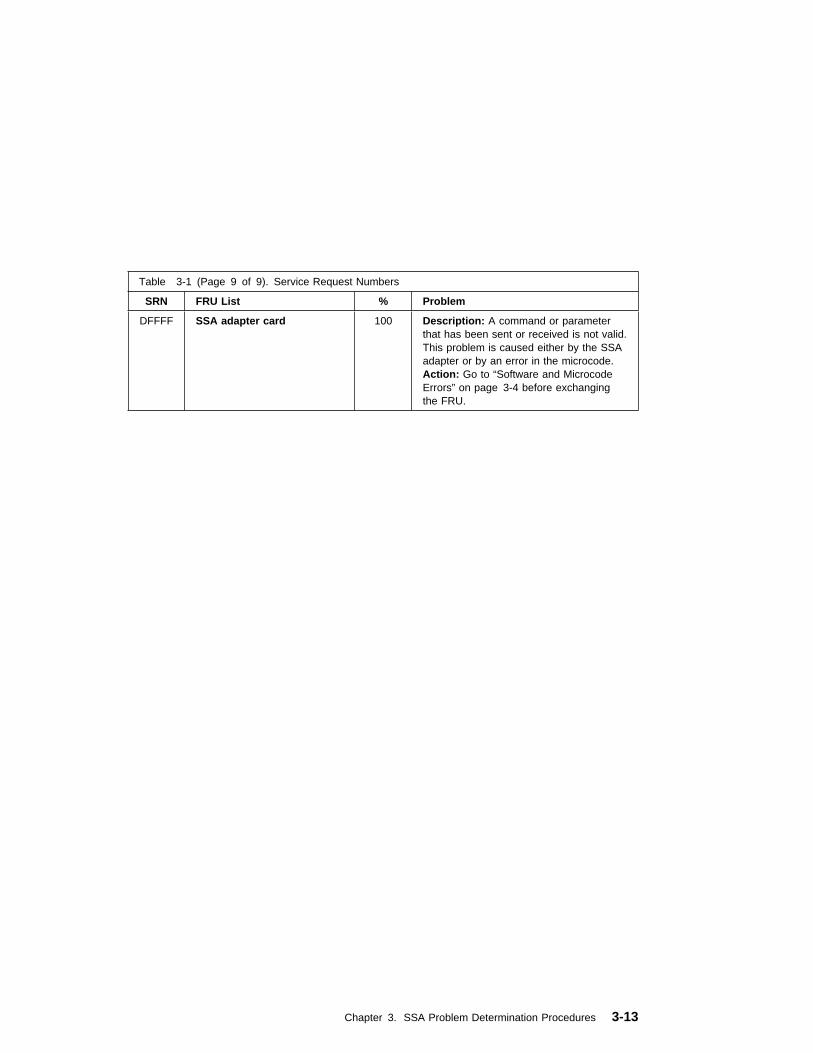
Table 3-1 (Page 9 of 9). Service Request Numbers
SRN FRU List % Problem
DFFFF SSA adapter card 100 Description: A command or parameterthat has been sent or received is not valid.This problem is caused either by the SSAadapter or by an error in the microcode.Action: Go to “Software and MicrocodeErrors” on page 3-4 before exchangingthe FRU.
Chapter 3. SSA Problem Determination Procedures 3-13
SSA Loop Configurations That Are Not Valid
Note: This section is related to SRN 48000.
SRN 48000 shows that the SSA loop contains more devices or adapters than areallowed. The following condition exist: the loop contains more than 48 devices.
If the SRN occurred when either you or the customer switched on the using system:
1. Switch off the using system.
2. Review the configuration that you are trying to make, and determine why thatconfiguration is not valid.
3. Correct your configuration by reconfiguring the SSA cables or by removing theexcess devices or adapters from the loop.
4. Switch on the using system.
If the SRN occurred because additional devices or adapters were added to a workingSSA loop:
1. Remove the additional devices or adapters that are causing the problem, and putthe loop back into its original, working configuration.
Note: It is important that you perform these actions, because they enable theconfiguration code to reset itself from the effects of the error.
2. Review the configuration that you are trying to make, and determine why thatconfiguration is not valid.
3. Correct your system to a valid configuration.
3-14 Service Guide
SSA Maintenance Analysis Procedures (MAPs)
These maintenance analysis procedures (MAPs) describe how to analyze acontinuous failure that has occurred in a system that contains two or more disk drivemodules. Failing field-replaceable units (FRUs) of the system unit can be isolatedwith these MAPs.
How to Use These MAPs
Attention: Switching off the power to an SSA Hot-Swap Disk Drive can cause asystem fault unless you first make the SSA Hot-Swap Disk Drive modulesunavailable to the system unit. To do this:
1. Use the system-management task menus to make the disk drive modulesunavailable.
2. If the system unit has more than one SSA adapter, make the SSA Hot-SwapDisk Drive modules unavailable to the system for each of the paths to the SSAHot-Swap Disk Drive.
Attention: Unless the system unit needs to be switched off for some other reason,do not switch off the power to the system unit when servicing an SSA Hot-Swap DiskDrive or the external SSA cable.
� To isolate the FRUs associated with in the failing SSA Hot-Swap Disk Drive,perform the actions and answer the questions given in this MAP.
� When instructed to exchange two or more FRUs in sequence:
1. Exchange the first FRU in the list for a new one.
2. Verify that the problem is solved. For some problems, verification meansrunning the diagnostic programs (see the using-system service procedures).
3. If the problem remains:
a. Reinstall the original FRU.
b. Exchange the next FRU in the list for a new one.
4. Repeat steps 2 and 3 until either the problem is solved, or all the relatedFRUs have been exchanged.
5. Perform the next action indicated by the MAP.
Chapter 3. SSA Problem Determination Procedures 3-15

MAP 2010: SSA Hot-Swap Disk Drive–Start
This MAP is the entry point to the MAPs for the SSA Hot-Swap Disk Drive. If youare not familiar with these MAPs, read “How to Use These MAPs” on page 3-15 first.
You might have been sent here because:
� The system problem determination procedures sent you here.
� Action from an SRN list sent you here.
� A problem occurred during the installation of an SSA Hot-Swap Disk Drivemodule.
� Another MAP sent you here.
� A customer observed a problem that was not detected by the system problemdetermination procedures.
Step 2010-1
Have you been sent to this MAP from the Configuration Verification service aid?
Yes Go to “Step 2010-2” on page 3-17.
No Go to “Step 2010-3” on page 3-18.
3-16 Service Guide
Step 2010-2
One of the following conditions exist. Take the action described.
1. You have an hdisk that has no associated pdisk.
a. Issue the system cfgmgr command.
b. Retry the Configuration Verification service aid.
c. If the problem remains, a software error has probably occurred. Call yoursupport center for assistance.
2. You have a pdisk that has no associated hdisk.
a. Run diagnostics (using system verification mode) to the pdisk.
b. If you get an SRN, go to Table 3-1 on page 3-5 and follow the actionsdescribed.
If you do not get an SRN, the disk formatting may be incompatible with thesystem (the disk was formatted on a different type of using system, that is,not an RS 6000).
1) Format the pdisk.
2) Issue the system cfgmgr command
3) Retry the Configuration Verification service aid.
3. If the problem remains, a software error has probably occurred. Call yoursupport center for assistance.
Chapter 3. SSA Problem Determination Procedures 3-17

Step 2010-3
Have the system diagnostics or problem determination procedures given you an SRNfor the SSA Hot-Swap Disk Drive?
No Go to “Step 2010-4.”
Yes Go to “Service Request Numbers (SRNs)” on page 3-3.
Step 2010-4
If the system diagnostics are available, go to “Step 2010-5.”
If the stand-alone diagnostics are available, but the system diagnostics are notavailable, run them, then go to “Step 2010-5.”
If the system diagnostics and stand-alone diagnostics are not available, go to “Step2010-1” on page 3-16.
Step 2010-5
Run the diagnostics in the problem determination mode.
Note: Do not run the advanced diagnostics, because errors are logged on otherusing systems that share the same loop.
Did the diagnostics give you an SRN for the SSA Hot-Swap Disk Drive?
No Go to “Step 2010-6” on page 3-19.
Yes Go to “Service Request Numbers (SRNs)” on page 3-3.
3-18 Service Guide

Step 2010-6
Are all LED's on the drives in a 6 pack off?
Yes Go to “Step 2010-7.”
No Go to step “Step 2010-9.”
Step 2010-7
Are any power cables loose or in need of replacement?
No Go to “Step 2010-8.”
Yes Fix or replace the power cables as required. Go to "MAP 410: RepairCheckout" in RS/6000 Diagnostic Information for Multiple Bus Systems toverify the repair.
Step 2010-8
Replace the backplane. Go to "MAP 410: Repair Checkout" in RS/6000 DiagnosticInformation for Multiple Bus Systems to verify the repair.
Step 2010-9
Is there only one drive with no LED's on?
No Go to step “Step 2010-10” on page 3-20.
Yes Replace the the following FRU's:
1. Backplane
2. Disk drive assembly
Go to "MAP 410: Repair Checkout" in RS/6000 Diagnostic Information forMultiple Bus Systems to verify the repair.
Chapter 3. SSA Problem Determination Procedures 3-19
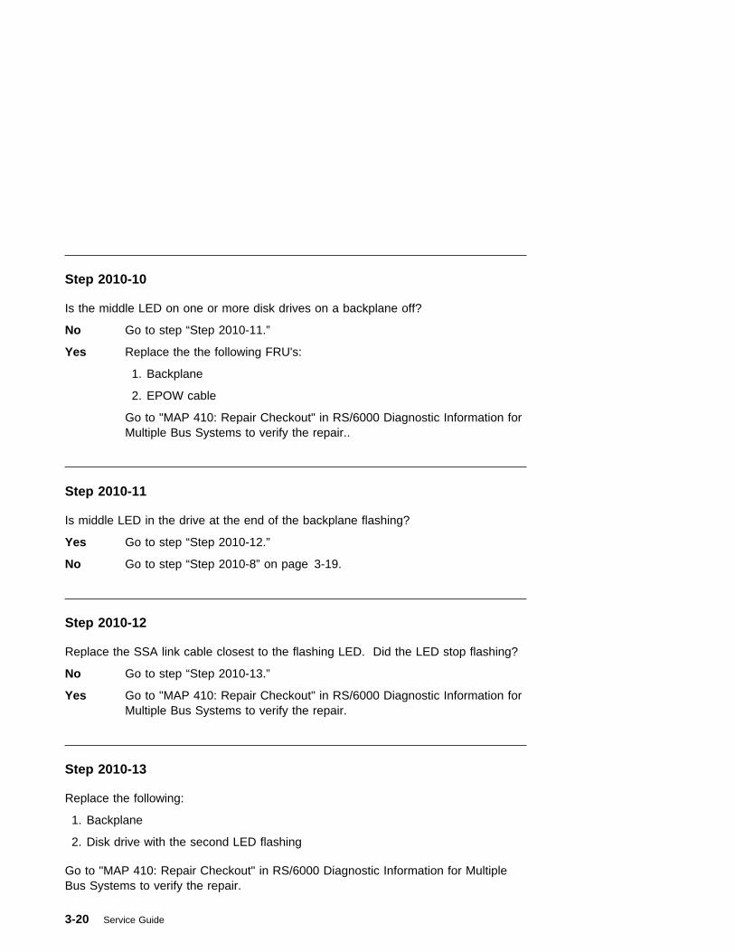
Step 2010-10
Is the middle LED on one or more disk drives on a backplane off?
No Go to step “Step 2010-11.”
Yes Replace the the following FRU's:
1. Backplane
2. EPOW cable
Go to "MAP 410: Repair Checkout" in RS/6000 Diagnostic Information forMultiple Bus Systems to verify the repair..
Step 2010-11
Is middle LED in the drive at the end of the backplane flashing?
Yes Go to step “Step 2010-12.”
No Go to step “Step 2010-8” on page 3-19.
Step 2010-12
Replace the SSA link cable closest to the flashing LED. Did the LED stop flashing?
No Go to step “Step 2010-13.”
Yes Go to "MAP 410: Repair Checkout" in RS/6000 Diagnostic Information forMultiple Bus Systems to verify the repair.
Step 2010-13
Replace the following:
1. Backplane
2. Disk drive with the second LED flashing
Go to "MAP 410: Repair Checkout" in RS/6000 Diagnostic Information for MultipleBus Systems to verify the repair.
3-20 Service Guide

Chapter 4. Error Code to FRU Index
The Error Code to FRU Index lists error symptoms and possible causes. The mostlikely cause is listed first. Use this index to help you decide which FRUs to replacewhen servicing the system.
If the codes in the following tables indicate a device which is present more than oncein the system unit, a location code is needed to specify which device generated theerror. Go to “Step 1020-4” on page 2-8 to display the System Management Serviceserror log and obtain a location code. Location code descriptions can be found under“Firmware Location Codes” on page 4-25.
If more than eight digits are displayed in the operator panel, use only the first eightdigits to find the error in the tables. The digits that display beyond the first eight digitsare location codes that can assist you in diagnosing the problem. See “FirmwareLocation Codes” on page 4-25.
Notes:
1. Licensed programs frequently rely on network configuration or system boardinformation to authorize program use. If the following tables indicate that thesystem board or network adapter should be replaced, notify the system ownerthat new keys for licensed programs may be required.
2. If a network adapter or the system board is replaced, the network administratormust be notified so that the client IP addresses used by the server can bechanged. In addition, the operating system configuration of the network controllermay need to be changed in order to enable system startup.
If you replace FRUs and the problem is still not corrected, go to MAP 0030 in theRS/6000 Diagnostic Information for Multiple Bus Systems unless otherwise indicatedin the tables.
Chapter 4. Error Code to FRU Index 4-1
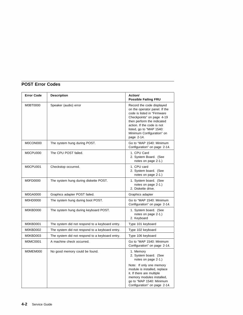
POST Error Codes
Error Code Description Action/Possible Failing FRU
M0BT0000 Speaker (audio) error Record the code displayedon the operator panel. If thecode is listed in “FirmwareCheckpoints” on page 4-19then perform the indicatedaction. If the code is notlisted, go to “MAP 1540:Minimum Configuration” onpage 2-14.
M0CON000 The system hung during POST. Go to “MAP 1540: MinimumConfiguration” on page 2-14.
M0CPU000 The CPU POST failed. 1. CPU Card 2. System Board. (See
notes on page 2-1.)
M0CPU001 Checkstop occurred. 1. CPU card 2. System board. (See
notes on page 2-1.)
M0FD0000 The system hung during diskette POST. 1. System board. (Seenotes on page 2-1.)
2. Diskette drive.
M0GA0000 Graphics adapter POST failed. Graphics adapter
M0HD0000 The system hung during boot POST. Go to “MAP 1540: MinimumConfiguration” on page 2-14.
M0KBD000 The system hung during keyboard POST. 1. System board. (Seenotes on page 2-1.)
2. Keyboard
M0KBD001 The system did not respond to a keyboard entry. Type 101 keyboard
M0KBD002 The system did not respond to a keyboard entry. Type 102 keyboard
M0KBD003 The system did not respond to a keyboard entry. Type 106 keyboard
M0MC0001 A machine check occurred. Go to “MAP 1540: MinimumConfiguration” on page 2-14.
M0MEM000 No good memory could be found. 1. Memory 2. System board. (See
notes on page 2-1.)
Note: If only one memorymodule is installed, replaceit. If there are multiplememory modules installed,go to “MAP 1540: MinimumConfiguration” on page 2-14.
4-2 Service Guide

Error Code Description Action/Possible Failing FRU
M0MEM001 No good memory could be found. 1. Memory 2. System board. (See
notes on page 2-1.)
M0MEM002 The system hung during memory POST. Go to “MAP 1540: MinimumConfiguration” on page 2-14.
M0NET000 Network error Record the code displayedon the operator panel. If thecode is listed in “FirmwareCheckpoints” on page 4-19,then perform the indicatedaction. If the code is notlisted, go to “MAP 1540:Minimum Configuration” onpage 2-14.
M0PS0000 Power failure. Go to “MAP 1520: Power” onpage 2-9.
M0SCSI00 Unable to load diagnostics. Go to “MAP 1540: MinimumConfiguration” on page 2-14.
M0SCSI01 Unable to load diagnostics. Go to “MAP 1540: MinimumConfiguration” on page 2-14.
M0SPK000 A continuous beep is heard from the system. System board. (See noteson page 2-1.)
M0SPK001 The system does not beep. 1. Speaker 2. System board. (See
notes on page 2-1.)
Chapter 4. Error Code to FRU Index 4-3
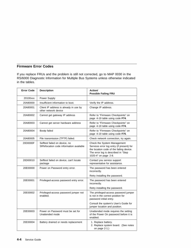
Firmware Error Codes
If you replace FRUs and the problem is still not corrected, go to MAP 0030 in theRS/6000 Diagnostic Information for Multiple Bus Systems unless otherwise indicatedin the tables.
Error Code Description Action/Possible Failing FRU
20100xxx Power Supply
20A80000 Insufficient information to boot. Verify the IP address.
20A80001 Client IP address is already in use byother network device
Change IP address.
20A80002 Cannot get gateway IP address Refer to “Firmware Checkpoints” onpage 4-19 table using code F74.
20A80003 Cannot get server hardware address Refer to “Firmware Checkpoints” onpage 4-19 table using code F74.
20A80004 Bootp failed Refer to “Firmware Checkpoints” onpage 4-19 table using code F75.
20A80005 File transmission (TFTP) failed. Check network connection, try again.
20D0000F Selftest failed on device, noSRN/location code information available
Check the System ManagementServices error log entry (if present) forthe location code of the failing device.The error log is described in “Step1020-4” on page 2-8.
20D00010 Selftest failed on device, can't locatepackage
Contact you service supportrepresentative for assistance.
20E00000 Power on Password entry error. The password has been enteredincorrectly.
Retry installing the password.
20E00001 Privileged-access password entry error. The password has been enteredincorrectly.
Retry installing the password.
20E00002 Privileged-access password jumper notenabled.
The privileged-access password jumperis not in the correct position forpassword initial entry.
Consult the system's User's Guide forjumper location and position.
20E00003 Power on Password must be set forUnattended mode
Unattended mode requires the settingof the Power On password before it isenabled.
20E00004 Battery drained or needs replacement 1. Replace battery.2. Replace system board. (See notes
on page 2-1.)
4-4 Service Guide
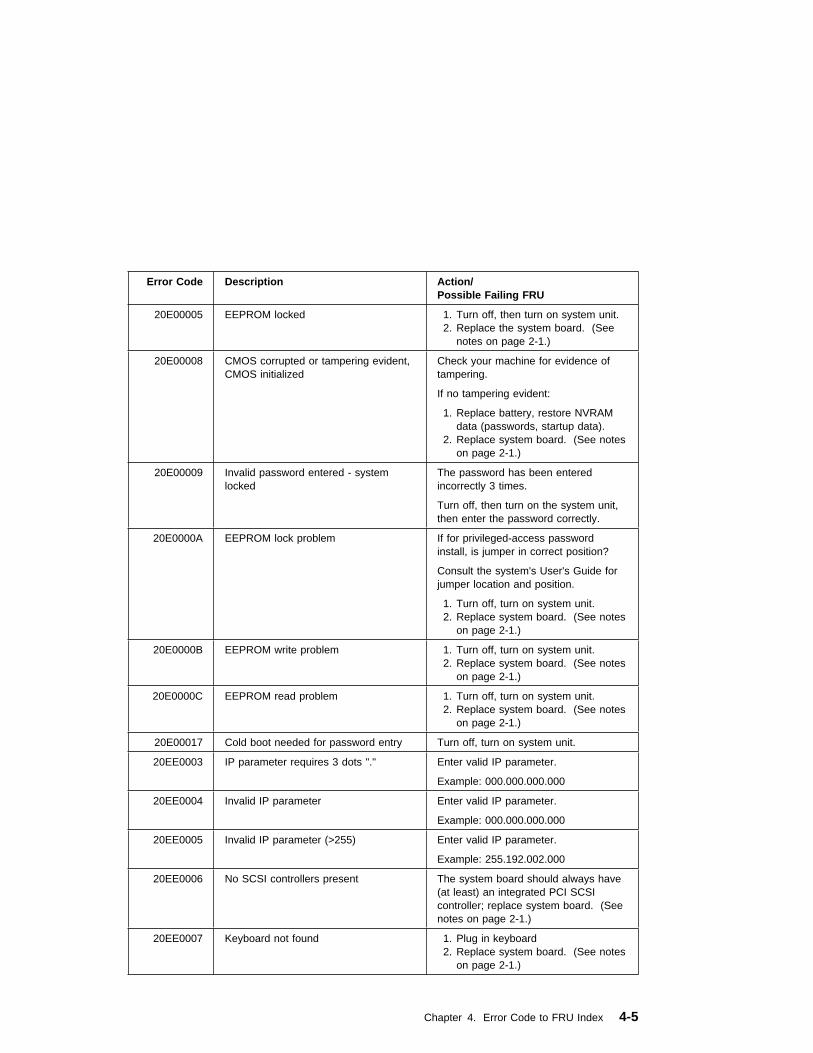
Error Code Description Action/Possible Failing FRU
20E00005 EEPROM locked 1. Turn off, then turn on system unit.2. Replace the system board. (See
notes on page 2-1.)
20E00008 CMOS corrupted or tampering evident,CMOS initialized
Check your machine for evidence oftampering.
If no tampering evident:
1. Replace battery, restore NVRAMdata (passwords, startup data).
2. Replace system board. (See noteson page 2-1.)
20E00009 Invalid password entered - systemlocked
The password has been enteredincorrectly 3 times.
Turn off, then turn on the system unit,then enter the password correctly.
20E0000A EEPROM lock problem If for privileged-access passwordinstall, is jumper in correct position?
Consult the system's User's Guide forjumper location and position.
1. Turn off, turn on system unit.2. Replace system board. (See notes
on page 2-1.)
20E0000B EEPROM write problem 1. Turn off, turn on system unit.2. Replace system board. (See notes
on page 2-1.)
20E0000C EEPROM read problem 1. Turn off, turn on system unit.2. Replace system board. (See notes
on page 2-1.)
20E00017 Cold boot needed for password entry Turn off, turn on system unit.
20EE0003 IP parameter requires 3 dots "." Enter valid IP parameter.
Example: 000.000.000.000
20EE0004 Invalid IP parameter Enter valid IP parameter.
Example: 000.000.000.000
20EE0005 Invalid IP parameter (>255) Enter valid IP parameter.
Example: 255.192.002.000
20EE0006 No SCSI controllers present The system board should always have(at least) an integrated PCI SCSIcontroller; replace system board. (Seenotes on page 2-1.)
20EE0007 Keyboard not found 1. Plug in keyboard2. Replace system board. (See notes
on page 2-1.)
Chapter 4. Error Code to FRU Index 4-5

Error Code Description Action/Possible Failing FRU
20EE0008 No configurable adapters found in thesystem
This warning occurs when the selectedSMS function cannot locate anydevices/adapters supported by thefunction. If a supported device isinstalled:
1. Replace the device or adapter
2. Replace riser card
3. Replace system board (See noteson page 2-1.)
21A00xxx SCSI disk drive Notes:
1. Before replacing any systemcomponents:
a. Ensure that the controller andeach device on the SCSI bus isassigned a unique SCSI ID.
b. Ensure SCSI bus is properlyterminated: SCSI cableplugged into system boardinternal SCSI port.
c. Ensure SCSI signal and powercables are securely connectedand not damaged.
2. The location code information isrequired to identify the ID of SCSIdevice failures as well as toindicate the location of thecontroller to which the device isattached.
xxx = 001 Test Unit Ready Failed - hardwareerror
1. SCSI device 2. SCSI cable 3. SCSI backplane 4. SCSI controller
xxx = 002 Test Unit Ready Failed - sense dataavailable
1. Media (Removable media devices) 2. SCSI device
xxx = 003 Send Diagnostic Failed SCSI device
xxx = 004 Send Diagnostic Failed - DevOfl cmd SCSI device
21E00xxx SCSI Tape Refer to 21A00xxx (SCSI disk drive) forxxx definitions.
21ED0xxx SCSI Changer Refer to 21A00xxx (SCSI disk drive) forxxx definitions.
21EE0xxx Other SCSI device type Refer to 21A00xxx (SCSI disk drive) forxxx definitions.
4-6 Service Guide

Error Code Description Action/Possible Failing FRU
21F00xxx SCSI CDROM Refer to 21A00xxx (SCSI disk drive) forxxx definitions.
21F20xxx SCSI Read/Write Optical Refer to 21A00xxx (SCSI disk drive) forxxx definitions.
25010xxx Flash
xxx = 000 No diskette in drive Insert diskette containing firmwareimage.
xxx = 001 Diskette seek error 1. Retry function.2. Replace diskette drive.3. Replace diskette cable.4. Replace system board. (See notes
on page 2-1.)
xxx = 002 Diskette in drive does not contain an*.IMG file.
Insert diskette with firmware update file.
xxx = 003 Cannot open OPENPROM package Replace system board. (See notes onpage 2-1.)
xxx = 004 Cannot find OPENPROM node Replace system board. (See notes onpage 2-1.)
xxx = 006 System id does not match imagesystem id
Make sure correct firmware updatediskette is being used with this system.
xxx = 007 Image has bad CRC Replace firmware updated diskette.
xxx = 008 Flash is write protected, updatecancelled
1. Turn off, turn on system unit andretry.
2. Replace system board. (See noteson page 2-1.)
xxx = 009 Flash module is unsupported or notrecognized
Make sure correct firmware updatediskette is being used with this system.
xxx = 00A Flash write protected. 1. Turn off, turn on system unit, retry.2. Replace system board. (See notes
on page 2-1.)
25A0xxy0 Cache L2 controller failure Refer to Error code 2B2xxyrr for adescription of the “xx” and “y” values.
1. CPU card2. System board.(See notes on page
2-1.)
Chapter 4. Error Code to FRU Index 4-7

Error Code Description Action/Possible Failing FRU
25A1xxy0 Cache L2 SRAM failure Refer to Error code 2B2xxyrr for adescription of the “xx” and “y” values.
1. CPU card2. System board. (See notes on
page 2-1.)
25A80xxx NVRAM Note: Errors reported against NVRAMcan be caused by low Battery voltageand (more rarely) power outages thatoccur during normal system usage.With the exception of the 25A80000error, these errors are warnings thatthe NVRAM data content had to bere-established and do not require anyFRU replacement unless the error ispersistent. When one of these errorsoccurs, any system customization (eg.boot device list) information has beenlost, the system may need to bere-configured.
If the error is persistent, replace thebattery.
If the error is persistent after batteryreplacement, or the error code is25A80000, replace the system board.(See notes on page 2-1.)
xxx = 000 Initialization failed, device test failed
xxx = 001 Init-nvram invoked, all of NVRAMinitialized
xxx = 002 Init-nvram invoked, GE area preserved,remaining areas initialized
xxx = 011 Data corruption detected, ALL ofNVRAM initialized
xxx = 012 Data corruption detected, GE areapreserved, remaining areas initialized
xxx = 100 NVRAM data validation check failed. Turn off, turn on system unit and retrythe operation.
4-8 Service Guide
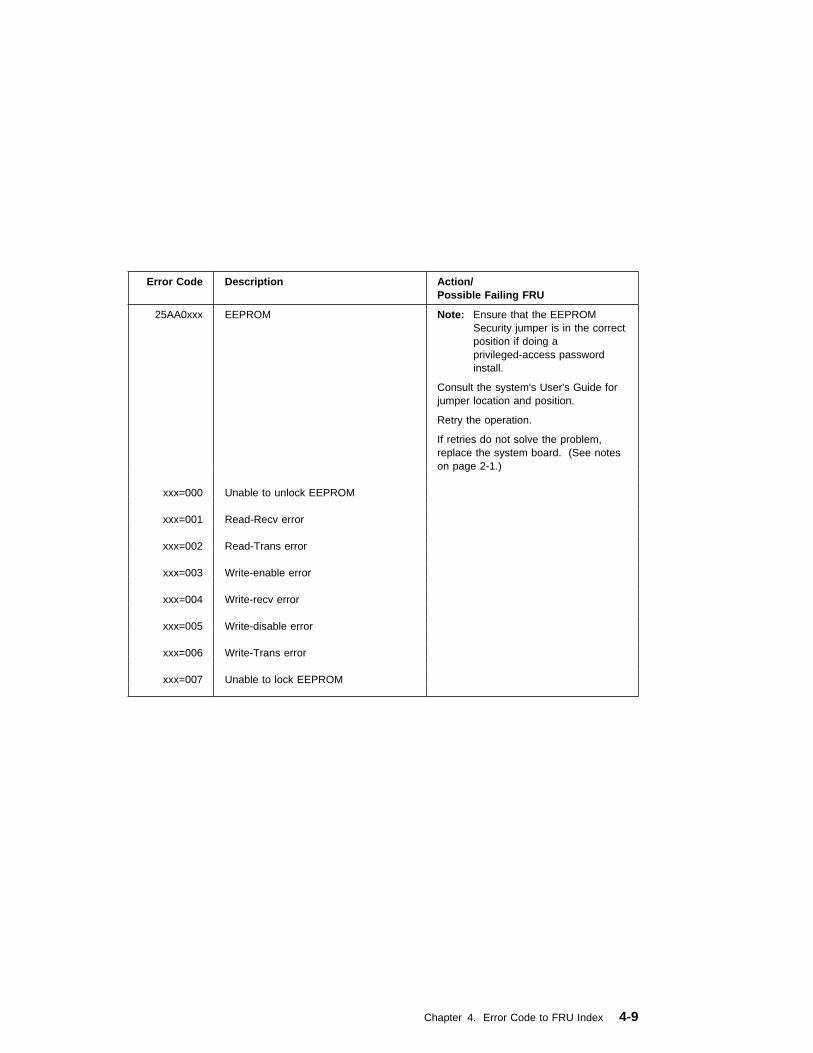
Error Code Description Action/Possible Failing FRU
25AA0xxx EEPROM Note: Ensure that the EEPROMSecurity jumper is in the correctposition if doing aprivileged-access passwordinstall.
Consult the system's User's Guide forjumper location and position.
Retry the operation.
If retries do not solve the problem,replace the system board. (See noteson page 2-1.)
xxx=000 Unable to unlock EEPROM
xxx=001 Read-Recv error
xxx=002 Read-Trans error
xxx=003 Write-enable error
xxx=004 Write-recv error
xxx=005 Write-disable error
xxx=006 Write-Trans error
xxx=007 Unable to lock EEPROM
Chapter 4. Error Code to FRU Index 4-9

Error Code Description Action/Possible Failing FRU
25Cyycsr Memory See “Memory PD Bits” on page 4-18for definition of "yy".
c = Memory card number (Always 0 forDIMM sockets on system planar.)
s = DIMM socket number (hex 0through F).
r = 1 DIMM fails memory test. For more information:
1. Use the location code obtainedfrom the SMS Error Log utility(described in “Step 1020-4” onpage 2-8) to identify which DIMMis defective.
2. The "yy" values specify type ofmemory causing error. See“Memory PD Bits” on page 4-18 fordefinition of "yy."
Note: There may be 2 DIMM relatedmemory errors reported to indicate aDIMM pair. One of the 2 indicatedDIMMs may be good, when replacingmemory on this system replace 1DIMM at a time, not both.
r = 2 DIMM is not supported. 1. Remove unsupported DIMM.2. The "yy" values specify type of
memory causing error. See“Memory PD Bits” on page 4-18 fordefinition of "yy."
Note: Memory DIMMs must beinstalled/removed in pairs.
4-10 Service Guide
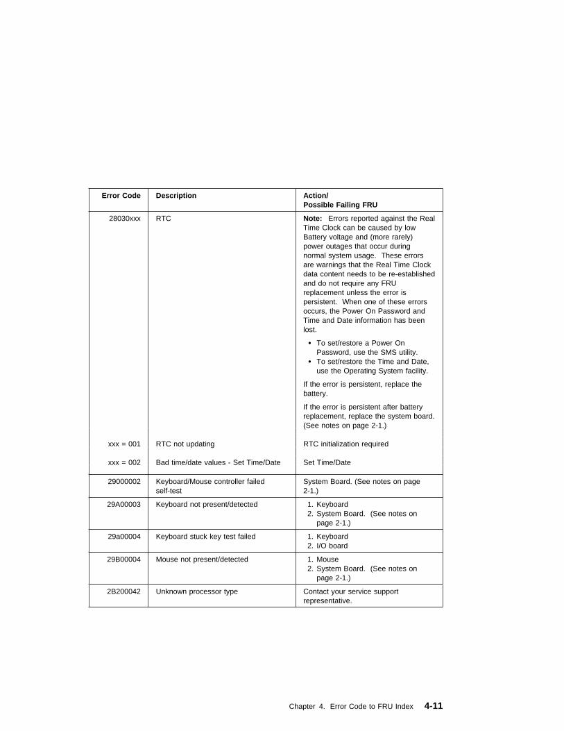
Error Code Description Action/Possible Failing FRU
28030xxx RTC Note: Errors reported against the RealTime Clock can be caused by lowBattery voltage and (more rarely)power outages that occur duringnormal system usage. These errorsare warnings that the Real Time Clockdata content needs to be re-establishedand do not require any FRUreplacement unless the error ispersistent. When one of these errorsoccurs, the Power On Password andTime and Date information has beenlost.
� To set/restore a Power OnPassword, use the SMS utility.
� To set/restore the Time and Date,use the Operating System facility.
If the error is persistent, replace thebattery.
If the error is persistent after batteryreplacement, replace the system board.(See notes on page 2-1.)
xxx = 001 RTC not updating RTC initialization required
xxx = 002 Bad time/date values - Set Time/Date Set Time/Date
29000002 Keyboard/Mouse controller failedself-test
System Board. (See notes on page2-1.)
29A00003 Keyboard not present/detected 1. Keyboard2. System Board. (See notes on
page 2-1.)
29a00004 Keyboard stuck key test failed 1. Keyboard 2. I/O board
29B00004 Mouse not present/detected 1. Mouse2. System Board. (See notes on
page 2-1.)
2B200042 Unknown processor type Contact your service supportrepresentative.
Chapter 4. Error Code to FRU Index 4-11
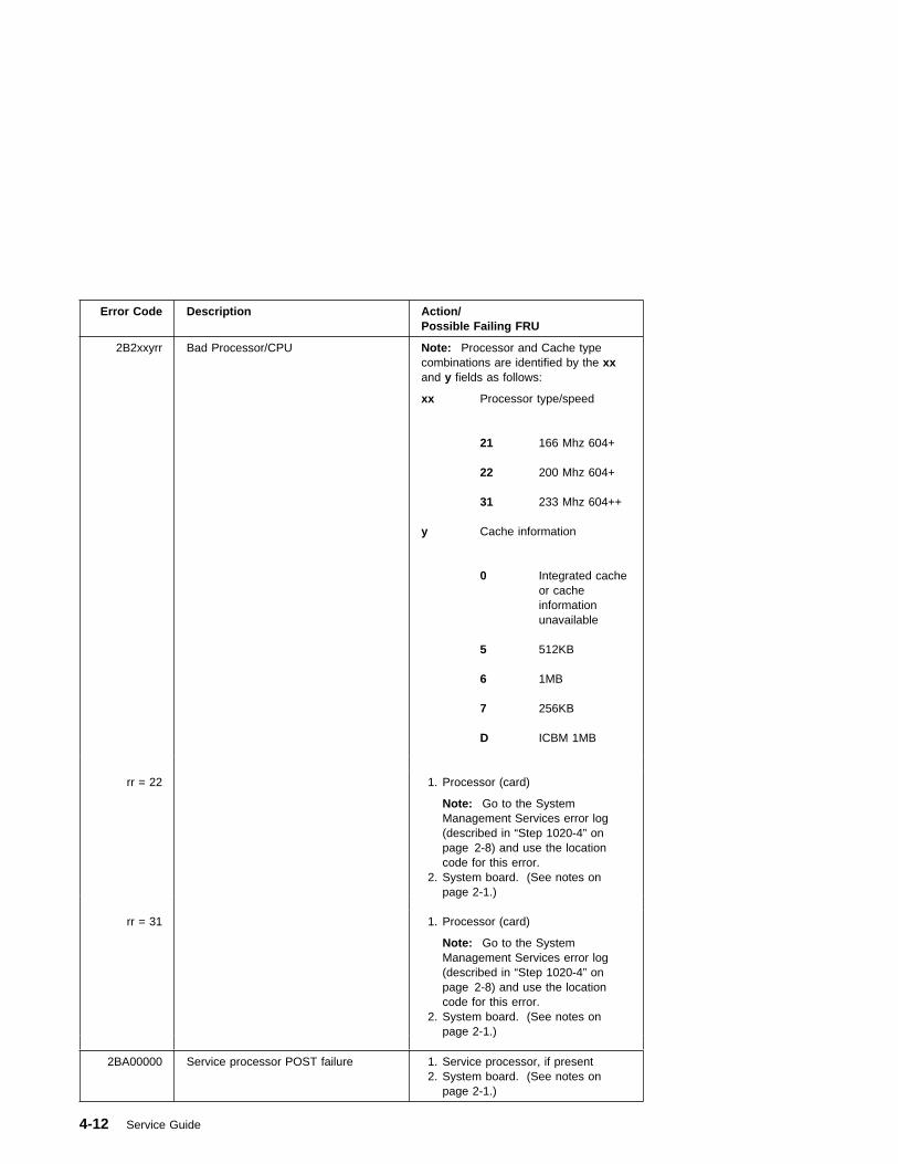
Error Code Description Action/Possible Failing FRU
2B2xxyrr Bad Processor/CPU Note: Processor and Cache typecombinations are identified by the xxand y fields as follows:
xx Processor type/speed
21 166 Mhz 604+
22 200 Mhz 604+
31 233 Mhz 604++
y Cache information
0 Integrated cacheor cacheinformationunavailable
5 512KB
6 1MB
7 256KB
D ICBM 1MB
rr = 22 1. Processor (card)
Note: Go to the SystemManagement Services error log(described in “Step 1020-4” onpage 2-8) and use the locationcode for this error.
2. System board. (See notes onpage 2-1.)
rr = 31 1. Processor (card)
Note: Go to the SystemManagement Services error log(described in “Step 1020-4” onpage 2-8) and use the locationcode for this error.
2. System board. (See notes onpage 2-1.)
2BA00000 Service processor POST failure 1. Service processor, if present2. System board. (See notes on
page 2-1.)
4-12 Service Guide
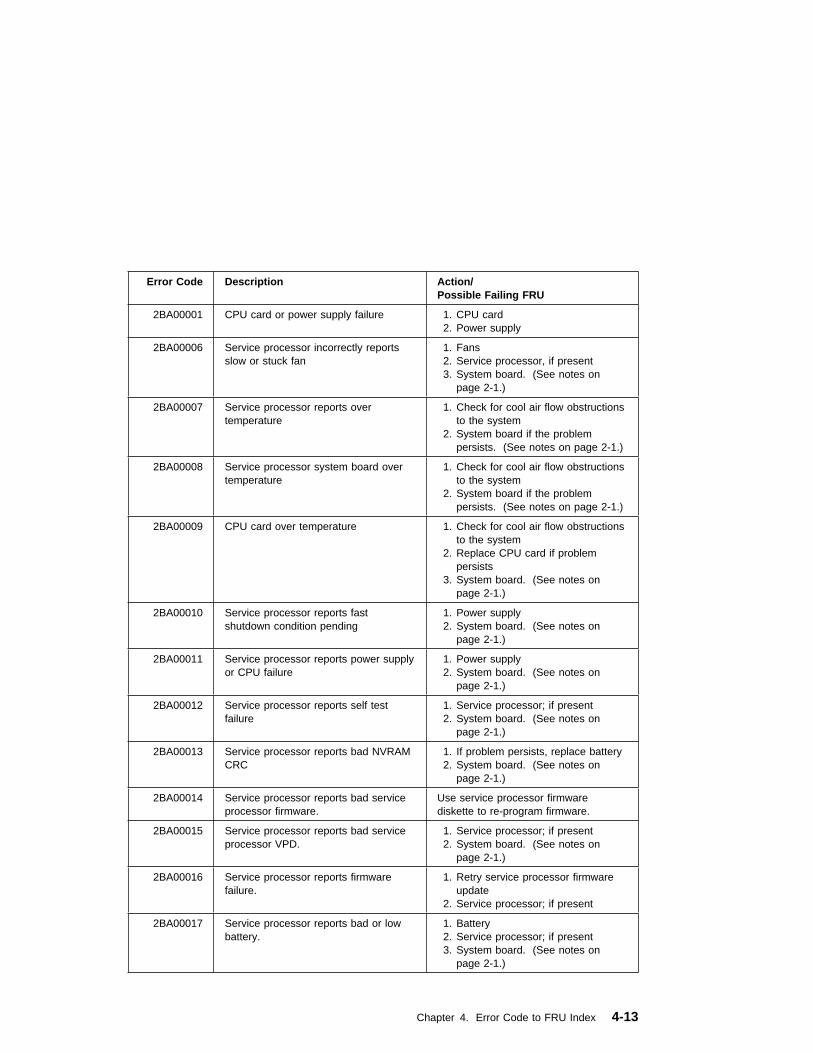
Error Code Description Action/Possible Failing FRU
2BA00001 CPU card or power supply failure 1. CPU card 2. Power supply
2BA00006 Service processor incorrectly reportsslow or stuck fan
1. Fans2. Service processor, if present3. System board. (See notes on
page 2-1.)
2BA00007 Service processor reports overtemperature
1. Check for cool air flow obstructionsto the system
2. System board if the problempersists. (See notes on page 2-1.)
2BA00008 Service processor system board overtemperature
1. Check for cool air flow obstructionsto the system
2. System board if the problempersists. (See notes on page 2-1.)
2BA00009 CPU card over temperature 1. Check for cool air flow obstructionsto the system
2. Replace CPU card if problempersists
3. System board. (See notes onpage 2-1.)
2BA00010 Service processor reports fastshutdown condition pending
1. Power supply2. System board. (See notes on
page 2-1.)
2BA00011 Service processor reports power supplyor CPU failure
1. Power supply2. System board. (See notes on
page 2-1.)
2BA00012 Service processor reports self testfailure
1. Service processor; if present2. System board. (See notes on
page 2-1.)
2BA00013 Service processor reports bad NVRAMCRC
1. If problem persists, replace battery2. System board. (See notes on
page 2-1.)
2BA00014 Service processor reports bad serviceprocessor firmware.
Use service processor firmwarediskette to re-program firmware.
2BA00015 Service processor reports bad serviceprocessor VPD.
1. Service processor; if present2. System board. (See notes on
page 2-1.)
2BA00016 Service processor reports firmwarefailure.
1. Retry service processor firmwareupdate
2. Service processor; if present
2BA00017 Service processor reports bad or lowbattery.
1. Battery2. Service processor; if present3. System board. (See notes on
page 2-1.)
Chapter 4. Error Code to FRU Index 4-13
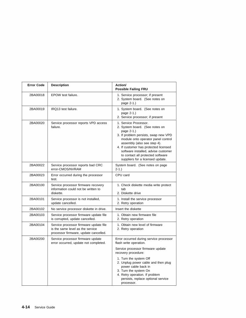
Error Code Description Action/Possible Failing FRU
2BA00018 EPOW test failure. 1. Service processor; if present2. System board. (See notes on
page 2-1.)
2BA00019 IRQ13 test failure. 1. System board. (See notes onpage 2-1.)
2. Service processor; if present
2BA00020 Service processor reports VPD accessfailure.
1. Service Processor.2. System board. (See notes on
page 2-1.)3. If problem persists, swap new VPD
module onto operator panel controlassembly (also see step 4).
4. If customer has protected licensedsoftware installed, advise customerto contact all protected softwaresuppliers for a licensed update.
2BA00022 Service processor reports bad CRCerror-CMOS/NVRAM
System board. (See notes on page2-1.)
2BA00023 Error occurred during the processortest.
CPU card
2BA00100 Service processor firmware recoveryinformation could not be written todiskette.
1. Check diskette media write protecttab
2. Diskette drive
2BA00101 Service processor is not installed,update cancelled.
1. Install the service processor 2. Retry operation
2BA00102 No service processor diskette in drive. Insert the diskette
2BA00103 Service processor firmware update fileis corrupted, update cancelled.
1. Obtain new firmware file 2. Retry operation
2BA00104 Service processor firmware update fileis the same level as the serviceprocessor firmware, update cancelled.
1. Obtain new level of firmware 2. Retry operation
2BA00200 Service processor firmware updateerror occurred, update not completed.
Error occurred during service processorflash write operation.
Service processor firmware updaterecovery procedure:
1. Turn the system Off2. Unplug power cable and then plug
power cable back in3. Turn the system On4. Retry operation. If problem
persists, replace optional serviceprocessor.
4-14 Service Guide
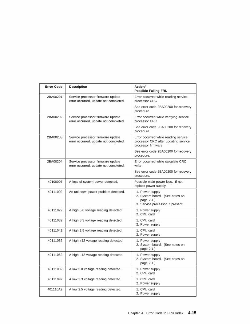
Error Code Description Action/Possible Failing FRU
2BA00201 Service processor firmware updateerror occurred, update not completed.
Error occurred while reading serviceprocessor CRC
See error code 2BA00200 for recoveryprocedure.
2BA00202 Service processor firmware updateerror occurred, update not completed.
Error occurred while verifying serviceprocessor CRC
See error code 2BA00200 for recoveryprocedure.
2BA00203 Service processor firmware updateerror occurred, update not completed.
Error occurred while reading serviceprocessor CRC after updating serviceprocessor firmware
See error code 2BA00200 for recoveryprocedure.
2BA00204 Service processor firmware updateerror occurred, update not completed.
Error occurred while calculate CRCwrite
See error code 2BA00200 for recoveryprocedure.
40100005 A loss of system power detected. Possible main power loss. If not,replace power supply.
40111002 An unknown power problem detected. 1. Power supply2. System board. (See notes on
page 2-1.)3. Service processor, if present
40111022 A high 5.0 voltage reading detected. 1. Power supply 2. CPU card
40111032 A high 3.3 voltage reading detected. 1. CPU card 2. Power supply
40111042 A high 2.5 voltage reading detected. 1. CPU card 2. Power supply
40111052 A high +12 voltage reading detected. 1. Power supply2. System board. (See notes on
page 2-1.)
40111062 A high −12 voltage reading detected. 1. Power supply2. System board. (See notes on
page 2-1.)
40111082 A low 5.0 voltage reading detected. 1. Power supply 2. CPU card
40111092 A low 3.3 voltage reading detected. 1. CPU card 2. Power supply
401110A2 A low 2.5 voltage reading detected. 1. CPU card 2. Power supply
Chapter 4. Error Code to FRU Index 4-15
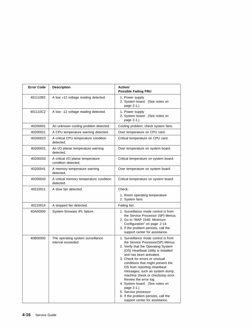
Error Code Description Action/Possible Failing FRU
401110B2 A low +12 voltage reading detected. 1. Power supply2. System board. (See notes on
page 2-1.)
401110C2 A low −12 voltage reading detected. 1. Power supply2. System board. (See notes on
page 2-1.)
40200001 An unknown cooling problem detected. Cooling problem; check system fans.
40200021 A CPU temperature warning detected. Over temperature on CPU card.
40200023 A critical CPU temperature conditiondetected.
Critical temperature on CPU card.
40200031 An I/O planar temperature warningdetected.
Over temperature on system board.
40200033 A critical I/O planar temperaturecondition detected.
Critical temperature on system board.
40200041 A memory temperature warningdetected.
Over temperature on system board.
40200043 A critical memory temperature conditiondetected.
Critical temperature on system board.
40210011 A slow fan detected. Check:
1. Room operating temperature 2. System fans
40210014 A stopped fan detected. Failing fan.
40A00000 System firmware IPL failure. 1. Surveillance mode control is fromthe Service Processor (SP) Menus.
2. Go to “MAP 1540: MinimumConfiguration” on page 2-14.
3. If the problem persists, call thesupport center for assistance.
40B00000 The operating system surveillanceinterval exceeded.
1. Surveillance mode control is fromthe Service Processor(SP) Menus.
2. Verify that the Operating System(OS) Heartbeat Utility is installedand has been activated.
3. Check for errors or unusualconditions that might prevent theOS from reporting Heartbeatmessages; such as system dump,machine check or checkstop error.Review the error log.
4. System board. (See notes onpage 2-1.)
5. Service processor6. If the problem persists, call the
support center for assistance.
4-16 Service Guide

Error Code Description Action/Possible Failing FRU
40D00003 An unknown slow shutdowncommanded.
Critical cooling problem.
40D00004 An unknown fast shutdowncommanded.
Locked fan failure detected.
4B201000 Checkstop. 1. CPU2. System board (See notes on page
2-1.)3. Go to “MAP 1540: Minimum
Configuration” on page 2-14. 4. Software problem 5. Firmware problem6. If the problem persists, call the
support center for assistance.
4B201010 Machine check. 1. CPU2. System board (See notes on page
2-1.) 3. Software problem 4. Firmware problem5. If the problem persists, call the
support center for assistance.
4B201020 TEA (transfer error acknowledge). 1. CPU2. System board (See notes on page
2-1.) 3. Software problem 4. Firmware problem5. If the problem persists, call the
support center for assistance.
Chapter 4. Error Code to FRU Index 4-17

Memory PD Bits
The following table expands the firmware error code 25Cyyxxx on page 4-10, whereyy is the PD values in the table below. Use these values to identify the type ofmemory that generated the error.
If you replace FRUs and the problem is still not corrected, go to MAP 0030 in theRS/6000 Diagnostic Information for Multiple Bus Systems unless otherwise indicatedin the tables.
PDvalue
Size
Speed(nsecs)
Parity/ECC
Single/Dual
64 8MB 60 ECC Single
69 16MB 60 ECC Single
6B 32MB 60 ECC Single
6D 64MB 60 ECC Single
6F 128MB 60 ECC Single
4-18 Service Guide

Firmware Checkpoints
The following Fxx code checkpoints occur during system startup, and can be usedfor diagnostic purposes.
If you replace FRUs and the problem is still not corrected, go to MAP 0030 in theRS/6000 Diagnostic Information for Multiple Bus Systems unless otherwise indicatedin the tables.
Checkpoint Description Action/Possible Failing FRU
A11 CPU reset failure Replace in the following order:
1. CPU card
2. Service Processor
3. System board. (See notes onpage 2-1.)
F05 Transfer control to OperatingSystem (normal boot).
See “Fxx Code Boot Problems” onpage 4-22.
F22 No memory detected (systemlockup) Note: Disk drive light is oncontinuously.
1. Memory modules2. System board. (See page 2-1.)
F4D Loading boot image See “Fxx Code Boot Problems” onpage 4-22.
F4F NVRAM initialization Refer to error code 25A80xxx in“Firmware Error Codes” onpage 4-4.
F51 Probing primary PCI bus 1. PCI Adapters 2. System board.
If a network adapter or systemboard is replaced, see page 2-1.
F52 Probing for adapter FCODE,evaluate if present
1. PCI Adapters 2. System board.
If a network adapter or systemboard is replaced, see page 2-1.
F55 Probing PCI bridge secondary bus 1. PCI Adapters 2. System board.
If a network adapter or systemboard is replaced, see page 2-1.
F5B Transferring control to OperatingSystem (service mode boot)
See “Fxx Code Boot Problems” onpage 4-22.
Chapter 4. Error Code to FRU Index 4-19

Checkpoint Description Action/Possible Failing FRU
F5F Probing for adapter FCODE,evaluate if present
1. PCI Adapters 2. System board.
If a network adapter or systemboard is replaced, see page 2-1.
F74 Establishing host connection Refer to “Fxx Code Boot Problems”on page 4-22 for generalconsiderations.
F75 BootP request Refer to “Fxx Code Boot Problems”on page 4-22 for generalconsiderations.
1. Turn off then on, and retry theboot operation.
2. Verify the network connection(network could be down).
3. Have network administratorverify the server configurationfor this client.
F9E Real time clock (RTC) initialization Refer to error code 28030xxx in“Firmware Error Codes” onpage 4-4.
FDC Dynamic console selection. Refer to “Fxx Code ConsoleProblems” on page 4-24.
FDD Processor exception System board (See notes on page2-1.)
FDE Alternating pattern of FDE and FADindicates a processor exception hasbeen detected.
System board (See notes on page2-1.)
FEA Firmware flash corrupted, load fromdiskette.
Ensure that the diskette installedcontains recovery image appropriatefor this system unit.
The System Management Servicesrecovery procedure for the flashEEPROM should be executed. See“Update” on page 6-22.
If the diskette is installed with thecorrect recovery image, thensuspect:
1. Diskette 2. Diskette drive 3. Diskette cable4. System board. (See notes on
page 2-1.)
4-20 Service Guide

Checkpoint Description Action/Possible Failing FRU
FEB Firmware flash corrupted, load fromdiskette.
Ensure that the diskette installedcontains recovery image appropriatefor this system unit.
The System Management Servicesrecovery procedure for the flashEEPROM should be executed. See“Update” on page 6-22.
If the diskette is installed with thecorrect recovery image, thensuspect:
1. Diskette 2. Diskette drive 3. Diskette cable4. System board. (See notes on
page 2-1.)
FF2 Power-On Password prompt. If a console is attached but nothingis displayed on it, go to the “EntryMAP” on page 2-1 with thesymptom "All display problems."
FF3 Privileged-Access Password prompt If a console is attached but nothingis displayed on it, go to the “EntryMAP” on page 2-1 with thesymptom "All display problems."
FFD The operator panel alternatesbetween the code FFD and anotherFxx code, where Fxx is the point atwhich the error occurred.
If the Fxx is not listed in this table,go to “MAP 1540: MinimumConfiguration” on page 2-14.
Fxx Problem not listed here Go to “MAP 1540: MinimumConfiguration” on page 2-14.
Chapter 4. Error Code to FRU Index 4-21
Fxx Code Boot Problems: Depending on the boot device, a checkpoint may bedisplayed on the operator panel for an extended period of time while the boot imageis retrieved from the device. This is particularly true for Tape and Network bootattempts. If the checkpoint/code is displayed for an extended time there may be aproblem loading the boot image from the device. If booting from CDROM or Tape,watch for “activity” on the drive's LED indicator. A blinking LED means that theloading of either the boot image or additional information required by the operatingsystem being booted is still in progress.
For network boot attempts, if the system is not connected to an active network or ifthe target server is inaccessible (this can also result from incorrect IP parametersbeing supplied), the system still attempts to boot and because time-out durations arenecessarily long to accommodate retries, the system may appear to be hung.
1. Restart the system and get to the Firmware SMS utilities. In the utilities check:� Is the intended boot device correctly specified in the boot sequence?� For network boot attempts:
– Are the IP parameters correct?– Attempt to “Ping” the target server using the SMS “Ping” utility.
2. If the checkpoint F05 or F5B is displayed for an extended time, there may be aproblem with the integrity of the boot image.� Try to boot and run standalone diagnostics against the system, particularly
against the intended boot device. If the diagnostics are successful, it may benecessary to perform an operating system specific recovery process, orreinstall the operating system.
3. If attempting to boot from a disk drive, CDROM, or tape drive:a. Try a different CD/Tape (unless booting from disk drive)b. Verify proper SCSI bus terminationc. Replace SCSI cabled. It is possible that another attached SCSI device is causing the problem.
Disconnect any other SCSI devices attached to the same controller as theone the boot device is attached to and retry the boot operation. If this issuccessful, one of the devices removed is causing the problem, re-attachdevices one by one and retry the boot operation until the problem recurs andreplace the device that caused the problem.
e. Replace SCSI adapter (if drive is attached to a card rather than the systemboard)
f. Replace SCSI driveg. It is possible that another installed adapter is causing the problem.
Remove all installed adapters except the one the boot device is attached to,try to boot the standalone diagnostics from a CDROM drive attached to theSCSI controller on the system board, and run the diagnostics against thesystem.
4-22 Service Guide
If this is successful, re-install adapters (and attached devices as applicable)that were removed, one at a time, and run the standalone diagnosticsagainst the system. If problem recurs, replace the last installed device oradapter.
h. Replace system board4. If attempting to boot from a Network controller:
a. Turn power Off then On and retry the boot operationb. Verify the network connection (network could be down)c. Verify that IP parameters are correctd. Try to “Ping” the target servere. Have network administrator verify the server configuration for this clientf. Replace network cableg. Replace network adapter (unless trying to boot using the ethernet controller
on the system board)h. It is possible that another installed adapter is causing the problem.
Remove all installed adapters except the one you are trying to boot, and tryto boot the standalone diagnostics from a CDROM drive attached to theSCSI controller on the system board. If this is successful, run the diagnosticsagainst the system, particularly against the target network bootcontroller/adapter.
If this is successful, re-install adapters (and attached devices as applicable)that were removed, one at a time, and run the diagnostics against thesystem. If problem recurs, replace the last installed device or adapter.
i. Replace system board (if not replaced in previous step)5. If you replaced the indicated FRUs and the problem is still not corrected, or the
above descriptions did not address your particular situation, go to "MAP 1540:Minimum Configuration".
Chapter 4. Error Code to FRU Index 4-23
Fxx Code Console Problems: If a console is attached but nothing is displayedon it, follow the steps associated with “All display problems” in the “Entry MAP” onpage 2-1. If the console selection screens can be seen on the terminals but there isno response to attempts to select the console:
1. If selecting the console with a keyboard attached to the system, replace thekeyboard. If replacing the keyboard does not fix the problem, replace the systemboard. (See notes on page 2-1.)
2. If selecting the console with an ASCII terminal, suspect the ASCII terminal. Usethe Problem Determination Procedures for the terminal. Replace the systemboard (See notes on page 2-1.) if these procedures do not reveal a problem.
Note: Terminal settings should be set to: � 9600 Baud � No Parity� 8 Data bits� 1 Stop bit
4-24 Service Guide
Firmware Location Codes
These codes can be found in the System Management Services error log asdescribed in “Step 1020-4” on page 2-8.
Location codes vary in length depending on the device being referenced. In general,if a location code is referring to an adapter or controller, the location code is 4 digits(eg. 04-01 identifies the device/controller /adapter on the PCI bus, in physical slot 1).If a device is optional and plugs into an adapter/controller, it is normally 8 digits (eg.01-C0-00-00 is identifying the first diskette drive).
Location Code format
The basic format of the location code is:
� For non-SCSI devices/drives AB-CD-EF-GH� For SCSI devices/drives (not controllers/adapters)
AB-CD-EF-G,H
“G” is the SCSI bus ID (PUN) of the device and “H” is the Logical UnitNumber (LUN).
The “AB” value identifies the bus type as follows:
The “CD” value depends on whether the device is integrated or a plug in adapter.For plug in adapters, the value is a decimal number in the range of 01 to 99 thatidentifies the system slot. For integrated devices (eg. the integrated PCI Ethernetcontroller), the value of “G” is an uppercase alphabetic character in the range from Ato Z and is generated based on the device “discovery” order as specified in the OpenFirmware 1275 specification for the “probe” process which translates into “DeviceTree” order.
The “EF” value, as generated by the firmware, is always 00.
The “GH” value (except for SCSI devices) is a subsystem dependent “index” valueindicating subordinate devices of the parent identified by the “AB-CD-EF” value.
Examples:
00 Processor bus01 ISA bus04 PCI bus05 PCMCIA bus
Chapter 4. Error Code to FRU Index 4-25

Note: The values used in the examples are representative of the format andrelationships described above.
00-00 System board00-00-00-00 Memory SIMM/DIMM in socket 101-A0 ISA bus Diskette Controller01-A0-00-01 2nd ISA bus Diskette drive00-00 2nd ISA bus Serial Port (Error code differentiates between 1st and 2nd)04-01 PCI Adapter in system slot 104-01-00-13,0 SCSI device at SCSI bus ID 13 (decimal) attached to the PCI SCSI controller in
system slot 104-D0 Integrated PCI Ethernet controller04-E0 1st Integrated PCI SCSI controller04-C0-00-13,0 SCSI device at SCSI bus ID 13 (decimal) attached to the first PCI SCSI
controller integrated on the system board.00-00 1st Processor (Proc 0)00-01 2nd Processor (Proc 1)04-F0 2nd Integrated PCI SCSI controller
4-26 Service Guide

Chapter 5. Loading the System Diagnostics
If no keys are pressed after the system unit power is turned on, the system unitsearches a list of devices (the default boot list) for a bootable image. If a bootableimage is found, then the system unit loads and starts the operating system. This iscalled a normal boot.
The system unit can also be booted from a custom boot list, which can be changedthrough the System Management Services.
If certain keys are pressed during system startup, the system unit searches thedefault or custom boot list for a bootable image to start in service mode instead ofnormal mode. After a successful service mode boot, the diagnostic programs arestarted automatically.
The following pages describe the default and custom boot lists, and how to boot fromthese in either normal or service mode.
Default Boot List
The default boot list is composed of the first device found of each of the followingtypes:
1. Diskette drive
2. CD-ROM drive
3. Disk Drive
4. Network device
If this default boot list is used during system startup, the system unit attempts to bootfrom the diskette drive, then the first CD-ROM drive encountered, then the first diskdrive encountered, and finally the first network connection encountered.
Custom Boot List
The contents of the custom boot list can be defined by using the graphical SystemManagement Services (see “Boot” on page 6-7) or the text-based SystemManagement Services (see “Select Boot Devices” on page 6-27). When the customboot list is utilized during system startup, system unit attempts to boot in turn fromeach specific device in the custom boot list.
Note: Only the specific devices contained in the custom boot list are checked for abootable image. Other devices of the same type are not searched for abootable image unless they are also specified in the custom boot list.
Chapter 5. Loading the System Diagnostics 5-1
If no bootable image is found in the custom boot list, then the system restarts andattempts to boot again.
If the custom boot list is discovered to be corrupted, the system rebuilds the customboot list according to the default boot list.
Service Mode Boot: Loading Diagnostics
The system unit can be booted in service mode (instead of normal mode) fromeither the default boot list or custom boot list. After a successful service mode boot,the diagnostic programs are started automatically.
Booting in Service Mode from the Default Boot List
To boot in service mode from the default boot list, do the following:
1. Verify with the system administrator and users that all programs will be stopped,then do so.
2. Insert the diagnostic CD-ROM into the CD-ROM drive, if you intend to runstandalone diagnostics.
3. Turn off the system.
4. Wait 30 seconds, then turn on the system.
5. When the keyboard indicator appears during startup, press the F5 key if thesystem console is a directly-attached keyboard, or the 5 key if the systemconsole is an ASCII terminal.
6. Enter any passwords.
Diagnostics loaded from CD-ROM are called standalone diagnostics. Since thedefault boot list checks the CD-ROM drive before the disk drive, this procedure isused to start standalone diagnostics.
Booting in Service Mode from the Custom Boot List
To boot in service mode from the custom boot list, do the following:
1. Verify with the system administrator and users that all programs will be stopped,then do so.
2. Turn off the system.
3. Wait 30 seconds, then turn on the system.
5-2 Service Guide

4. When the keyboard indicator appears during startup, press the F6 key if thesystem console is a directly-attached keyboard, or the 6 key if the systemconsole is an ASCII terminal.
5. Enter any passwords.
Diagnostics loaded from a disk drive or network are called online diagnostics.(Online diagnostics can be used only if AIX is installed.) Since the custom boot listshould list the disk drive or network device before the CD-ROM drive, this procedureis used to start online diagnostics. To ensure that using the custom boot list startsonline diagnostics, do not insert the diagnostics CD-ROM.
Chapter 5. Loading the System Diagnostics 5-3

Standalone vs. Online Diagnostics
When the system unit attempts to boot in service mode (from either the default orcustom boot list) and locates a diagnostics CD-ROM before any other bootableimage, then the system unit starts standalone diagnostics.
Standalone diagnostics can be used on system units installed with any supportedoperating system.
When the system unit attempts to boot in service mode (from either the default orcustom boot list) and first locates a bootable image on disk drive or networkconnection, then the system unit starts online diagnostics.
Online diagnostics can only be used on system units installed with the AIX operatingsystem.
Because the type of diagnostics started (standalone or online) depends on thesource from which they are loaded, changing the boot list used during system startupcan affect which diagnostics are run.
Recommended Boot Options
The procedures under “Service Mode Boot: Loading Diagnostics” on page 5-2produce the following recommended results:
� Default boot list (F5 or 5 key) with diagnostics CD-ROM inserted loadsStandalone Diagnostics.
� Custom boot list (F6 or 6 key) without diagnostics CD-ROM inserted loadsOnline Diagnostics, if AIX is installed on a device in the custom boot list.
5-4 Service Guide
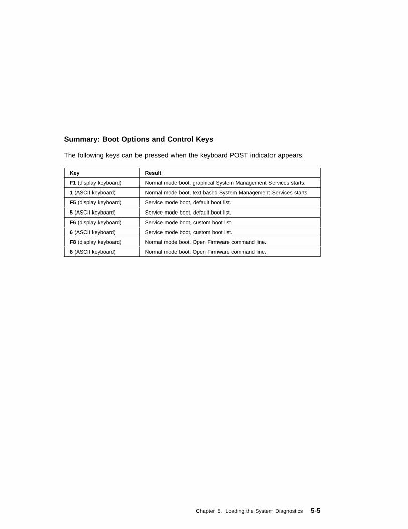
Summary: Boot Options and Control Keys
The following keys can be pressed when the keyboard POST indicator appears.
Key Result
F1 (display keyboard) Normal mode boot, graphical System Management Services starts.
1 (ASCII keyboard) Normal mode boot, text-based System Management Services starts.
F5 (display keyboard) Service mode boot, default boot list.
5 (ASCII keyboard) Service mode boot, default boot list.
F6 (display keyboard) Service mode boot, custom boot list.
6 (ASCII keyboard) Service mode boot, custom boot list.
F8 (display keyboard) Normal mode boot, Open Firmware command line.
8 (ASCII keyboard) Normal mode boot, Open Firmware command line.
Chapter 5. Loading the System Diagnostics 5-5

5-6 Service Guide
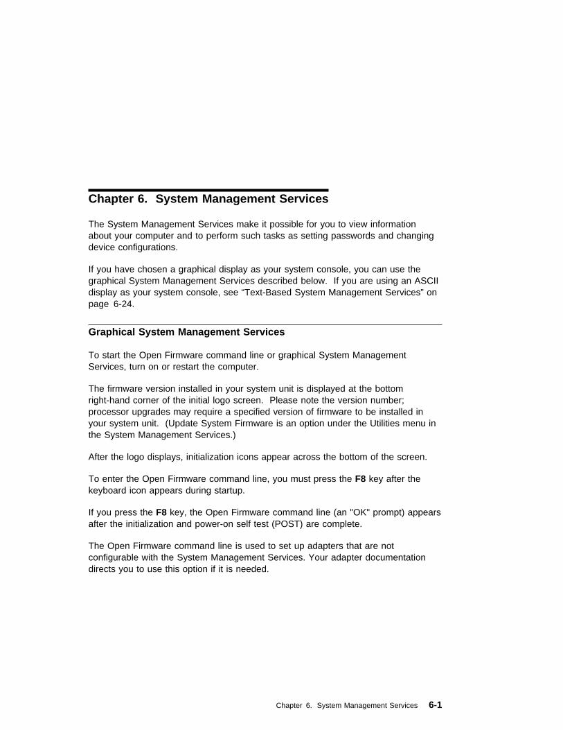
Chapter 6. System Management Services
The System Management Services make it possible for you to view informationabout your computer and to perform such tasks as setting passwords and changingdevice configurations.
If you have chosen a graphical display as your system console, you can use thegraphical System Management Services described below. If you are using an ASCIIdisplay as your system console, see “Text-Based System Management Services” onpage 6-24.
Graphical System Management Services
To start the Open Firmware command line or graphical System ManagementServices, turn on or restart the computer.
The firmware version installed in your system unit is displayed at the bottomright-hand corner of the initial logo screen. Please note the version number;processor upgrades may require a specified version of firmware to be installed inyour system unit. (Update System Firmware is an option under the Utilities menu inthe System Management Services.)
After the logo displays, initialization icons appear across the bottom of the screen.
To enter the Open Firmware command line, you must press the F8 key after thekeyboard icon appears during startup.
If you press the F8 key, the Open Firmware command line (an "OK" prompt) appearsafter the initialization and power-on self test (POST) are complete.
The Open Firmware command line is used to set up adapters that are notconfigurable with the System Management Services. Your adapter documentationdirects you to use this option if it is needed.
Chapter 6. System Management Services 6-1
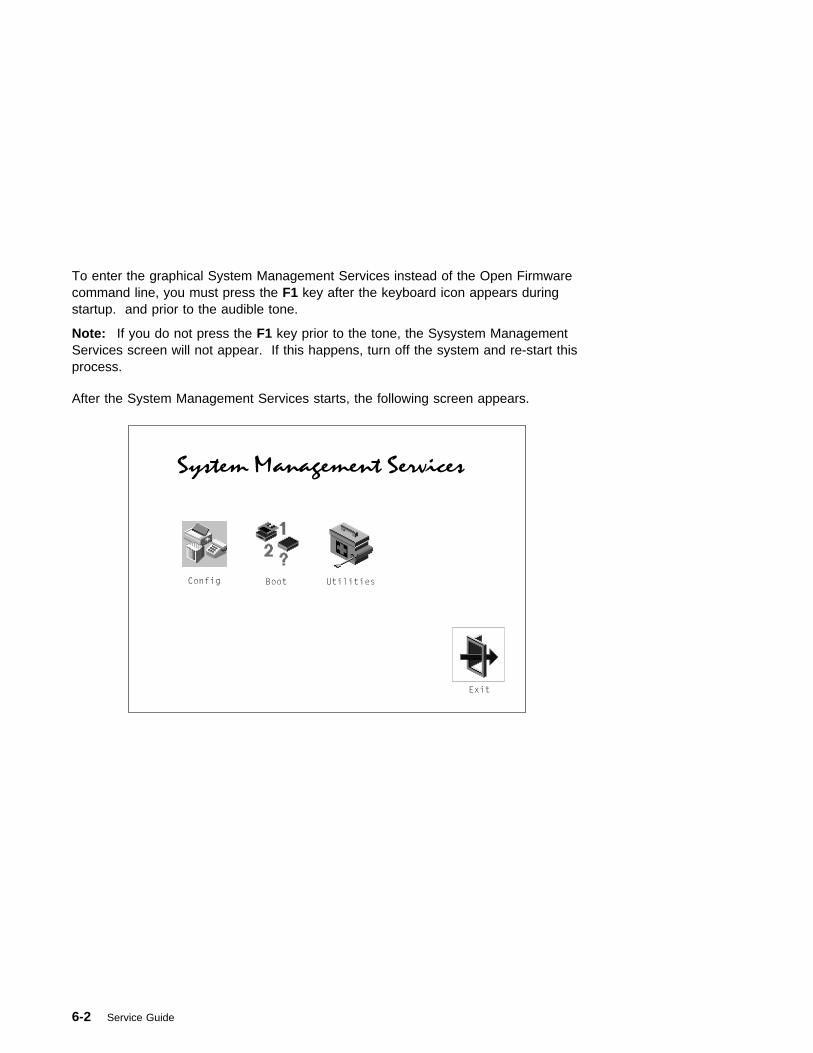
To enter the graphical System Management Services instead of the Open Firmwarecommand line, you must press the F1 key after the keyboard icon appears duringstartup. and prior to the audible tone.
Note: If you do not press the F1 key prior to the tone, the Sysystem ManagementServices screen will not appear. If this happens, turn off the system and re-start thisprocess.
After the System Management Services starts, the following screen appears.
6-2 Service Guide
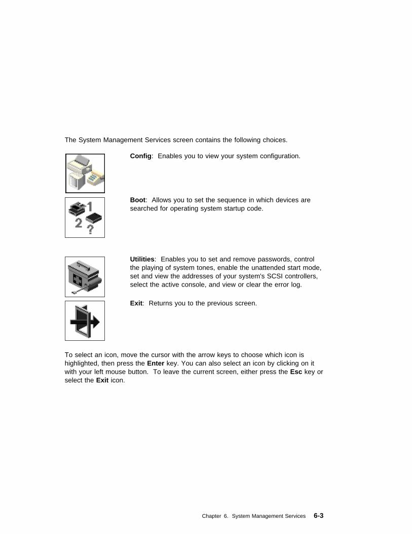
The System Management Services screen contains the following choices.
Config: Enables you to view your system configuration.
Boot: Allows you to set the sequence in which devices aresearched for operating system startup code.
Utilities: Enables you to set and remove passwords, controlthe playing of system tones, enable the unattended start mode,set and view the addresses of your system's SCSI controllers,select the active console, and view or clear the error log.
Exit: Returns you to the previous screen.
To select an icon, move the cursor with the arrow keys to choose which icon ishighlighted, then press the Enter key. You can also select an icon by clicking on itwith your left mouse button. To leave the current screen, either press the Esc key orselect the Exit icon.
Chapter 6. System Management Services 6-3
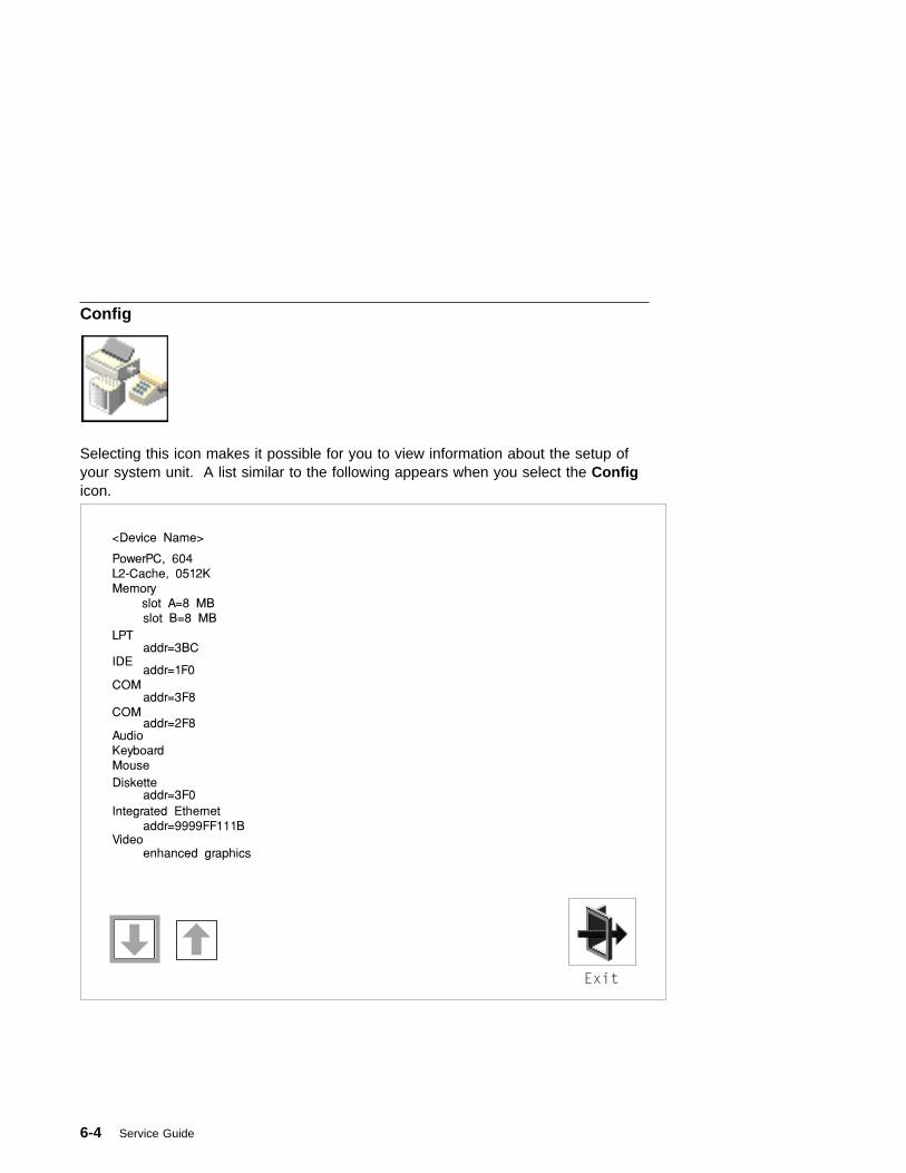
Config
Selecting this icon makes it possible for you to view information about the setup ofyour system unit. A list similar to the following appears when you select the Configicon.
6-4 Service Guide

Selecting the down arrow displays the next configuration screen, which lists yourcomputer's firmware version, the date of its development, and the firmware partnumber.
The following screen appears if you DO NOT have a service processor in yoursystem.
Chapter 6. System Management Services 6-5
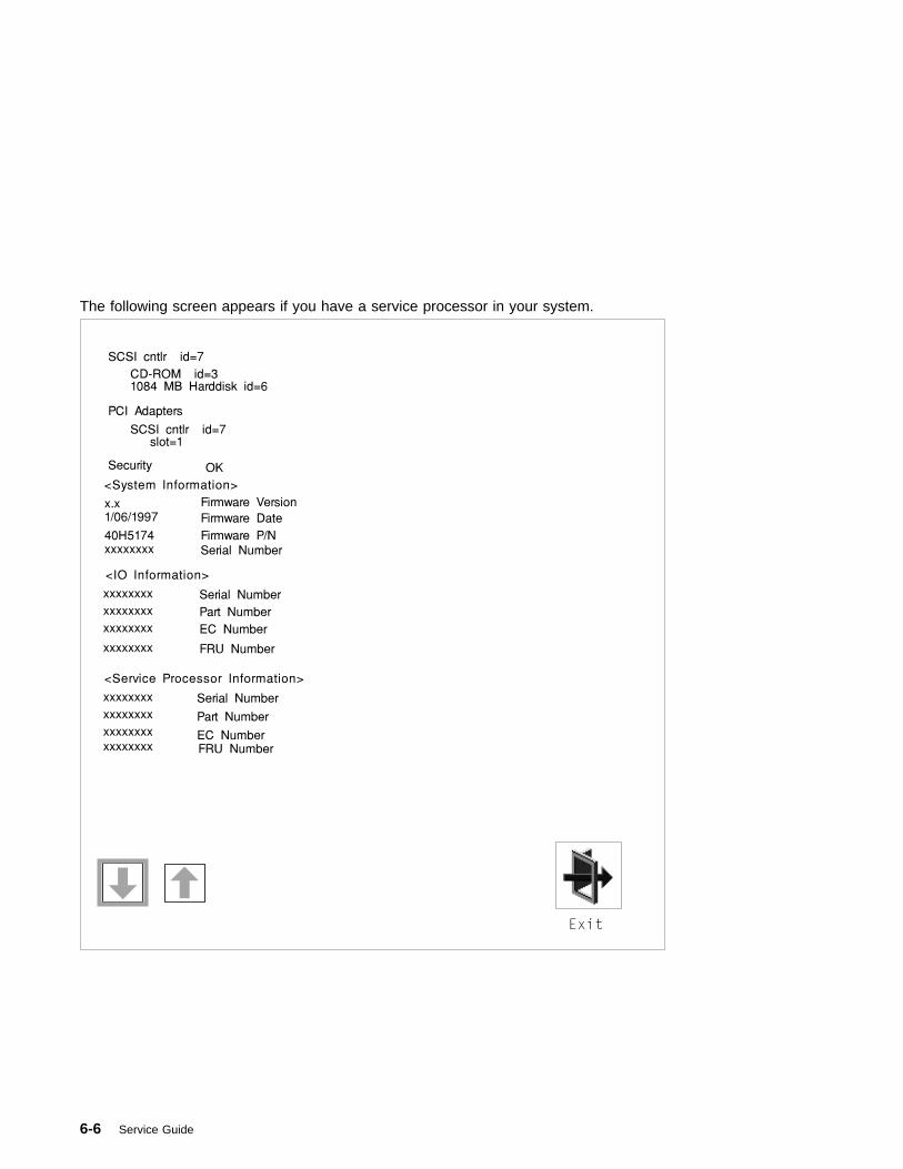
The following screen appears if you have a service processor in your system.
6-6 Service Guide

Boot
This selection enables you to view and change the custom boot list (the sequence inwhich devices are searched for operating system startup code).
Attention: If you change your startup sequence, you must be extremely carefulwhen performing write operations (for example, copying, saving, or formatting). Youcan accidentally overwrite data or programs if you select the wrong drive.
The default boot sequence is:
� The primary diskette drive
� CD-ROM drive
� Hard disk drive
� Network device.
Chapter 6. System Management Services 6-7
To change the custom boot list, enter a new order in the New column, then selectSave. The List of Boot Devices is updated to reflect the order you have chosen.
You can choose 1 to 4 devices for the custom boot list. To change the bootsequence back to the default values, select Default. (The default sequence isautomatically saved.)
6-8 Service Guide
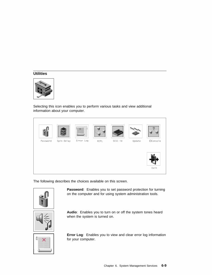
Utilities
Selecting this icon enables you to perform various tasks and view additionalinformation about your computer.
The following describes the choices available on this screen.
Password: Enables you to set password protection for turningon the computer and for using system administration tools.
Audio: Enables you to turn on or off the system tones heardwhen the system is turned on.
Error Log: Enables you to view and clear error log informationfor your computer.
Chapter 6. System Management Services 6-9
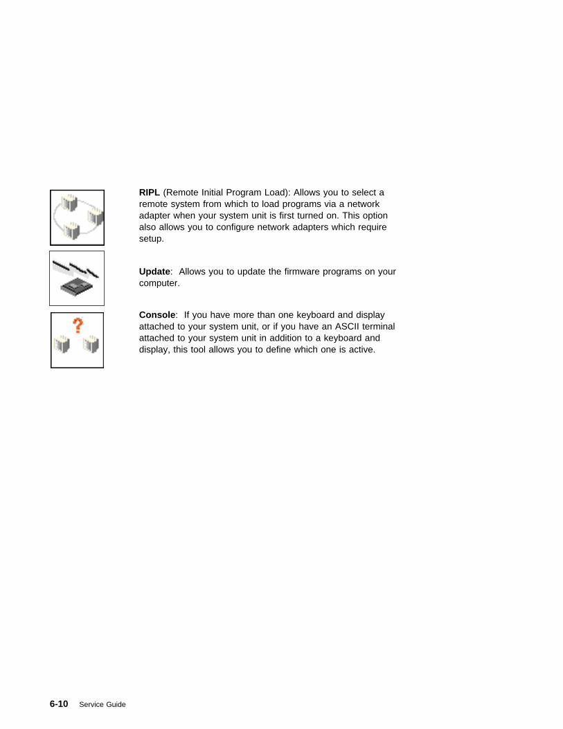
RIPL (Remote Initial Program Load): Allows you to select aremote system from which to load programs via a networkadapter when your system unit is first turned on. This optionalso allows you to configure network adapters which requiresetup.
Update: Allows you to update the firmware programs on yourcomputer.
Console: If you have more than one keyboard and displayattached to your system unit, or if you have an ASCII terminalattached to your system unit in addition to a keyboard anddisplay, this tool allows you to define which one is active.
6-10 Service Guide

Password
When you select this icon, the following screen is displayed.
Power-On Password: Setting a power-on password helps protect information storedin your computer. If a power-on password is set for your computer, the Power Onicon is shown in the locked position; if a power-on password is not set, then thePower On icon is shown in the unlocked position (as in the screen above).
When you select the Entry icon, a screen with 8 empty boxes appears. Type yourpassword in these boxes. You can use any combination of up to eight characters(A–Z, a–z, and 0–9) for your password. As you type a character, a key appears inthe box.
Enter Password
Chapter 6. System Management Services 6-11

Press Enter when you are finished; you are required to type the password again forverification.
Verify Password
If you make a mistake, press the Esc key and start again.
After you have entered and verified the password, the power-on password iconflashes and changes to the locked position to indicate that the power-on password isset.
If you previously had set a power-on password and want to remove it, select theRemove icon.
Note: If you forget the power-on password, you must remove the battery for at least30 seconds to disable this password. See “Battery” on page 7-46 for details.
A password can be set only after the system is turned off and on again.
6-12 Service Guide
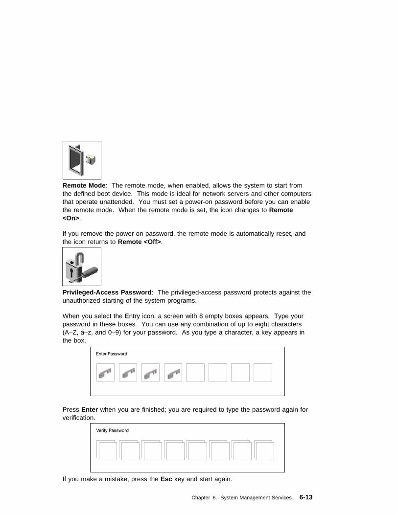
Remote Mode: The remote mode, when enabled, allows the system to start fromthe defined boot device. This mode is ideal for network servers and other computersthat operate unattended. You must set a power-on password before you can enablethe remote mode. When the remote mode is set, the icon changes to Remote<On>.
If you remove the power-on password, the remote mode is automatically reset, andthe icon returns to Remote <Off>.
Privileged-Access Password: The privileged-access password protects against theunauthorized starting of the system programs.
When you select the Entry icon, a screen with 8 empty boxes appears. Type yourpassword in these boxes. You can use any combination of up to eight characters(A–Z, a–z, and 0–9) for your password. As you type a character, a key appears inthe box.
Enter Password
Press Enter when you are finished; you are required to type the password again forverification.
Verify Password
If you make a mistake, press the Esc key and start again.
Chapter 6. System Management Services 6-13

After you have entered and verified the password, the privileged-access passwordicon flashes and changes to the locked position to indicate that your computer nowrequires the password you just entered before running system programs.
Note: If you forget the privileged-access password, you must remove the battery forat least 30 seconds to disable this password. See “Battery” on page 7-46 fordetails.
6-14 Service Guide
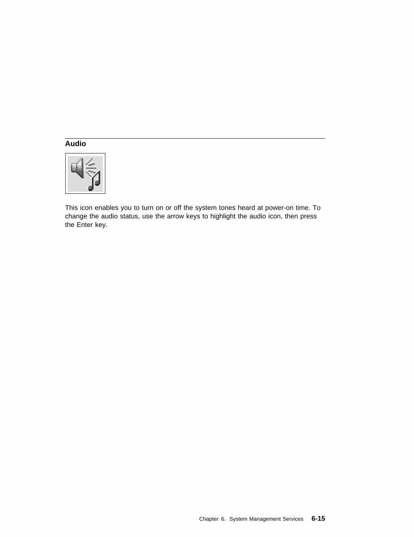
Audio
This icon enables you to turn on or off the system tones heard at power-on time. Tochange the audio status, use the arrow keys to highlight the audio icon, then pressthe Enter key.
Chapter 6. System Management Services 6-15

Error Log
Selecting this icon displays the log of the first and the last errors your computer hasencountered during operations.
Clear
System Error Log
Exit
2. No entry
1. 00/04/13 00:51:32 25C38005 P1-M1.10
Date Time Error Code Location
Selecting the Clear icon erases the entries in this log.
6-16 Service Guide
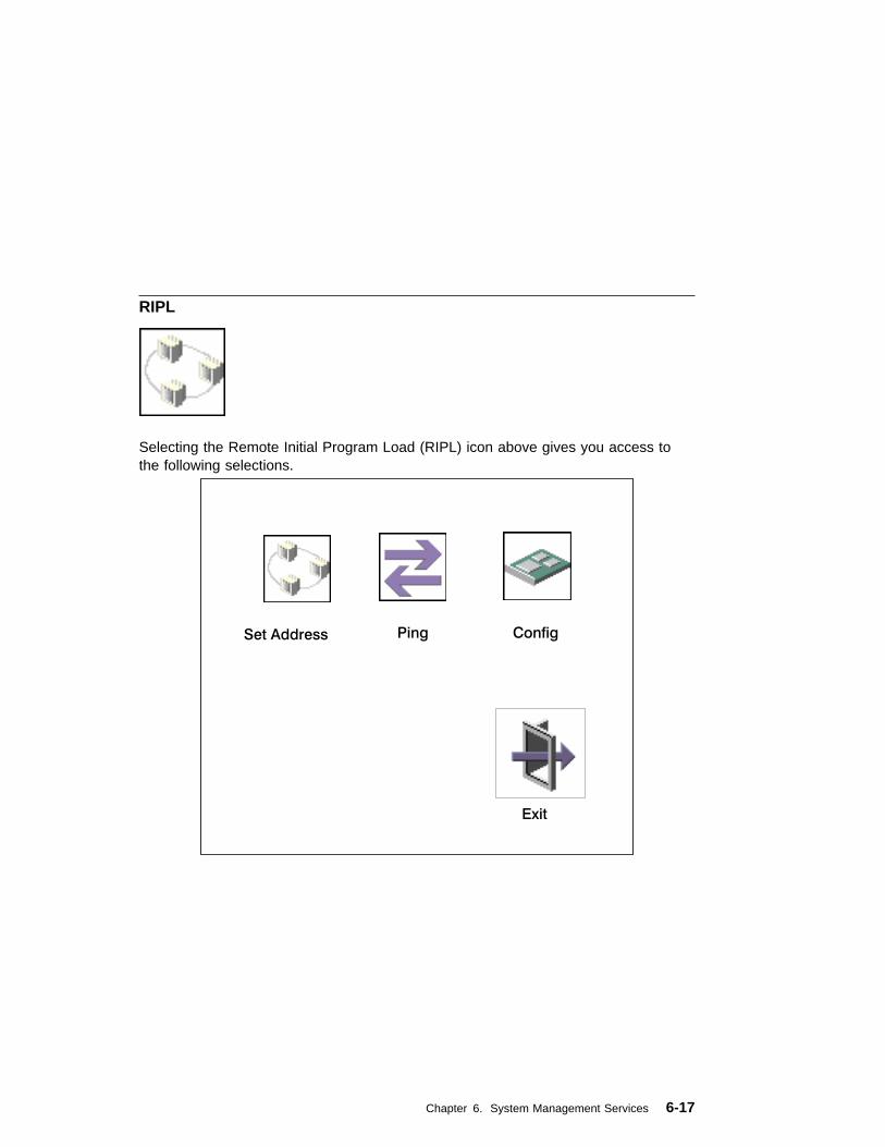
RIPL
Selecting the Remote Initial Program Load (RIPL) icon above gives you access tothe following selections.
Set Address
Exit
Ping Config
Chapter 6. System Management Services 6-17

The Set Address icon allows you to define addresses from which your computer canreceive RIPL code.
Notes:
1. Those addresses indicated with an (*) are required.
2. Some applications may require that IP addresses contain leading zeroes fornumbers less than 100. For example, 129.132.4.20 may need to be entered as123.132.004.020. If you are using the NIM application, do not specify leadingzeroes in the IP parameters section. Leading zeroes can cause subsequentattempts to initiate a network boot to fail.
If any of the addresses is incomplete or contains a number other than 0 to 255, anerror message is displayed when you select the Save icon. To clear this error,change the improper address and select Save again.
6-18 Service Guide

The Ping icon allows you to confirm that a specified address is valid by sending atest transmission to that address.
After choosing the Ping option, you may be asked to indicate which communicationsadapter (Token Ring or Ethernet) should be used to send the test transmission.
Chapter 6. System Management Services 6-19

The Config icon allows you to configure network adapters which require setup.Selecting the Config icon presents a list of the adapters requiring configuration. Usethe arrow keys to highlight an adapter, press the spacebar to select the adapter, thenhighlight the OK icon and press the Enter key.
The next screen allows you to select the type of adapter you have just chosen (orallow the system to select the type automatically). You can also select thecommunications mode of the chosen adapter (or allow the system to select thecommunications mode automatically). As on the previous screen, use the arrowkeys to highlight, press the space bar to select, then highlight the OK icon and pressenter.
After choosing the adapter to configure, you can select the communications mode ofthe chosen adapter (or allow the system to select the communications modeautomatically). As on the previous screen, use the arrow keys or mouse to highlight,then press the spacebar to select. When you have selected the communicationsmode, highlight the OK icon and press the Enter key.
6-20 Service Guide
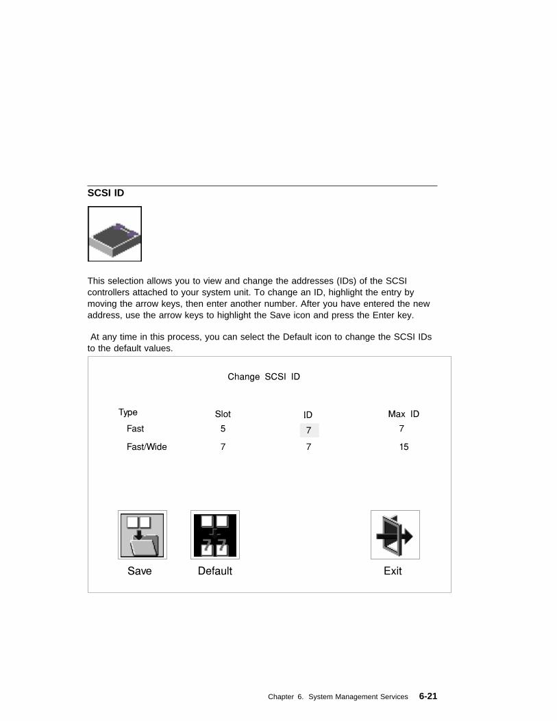
SCSI ID
This selection allows you to view and change the addresses (IDs) of the SCSIcontrollers attached to your system unit. To change an ID, highlight the entry bymoving the arrow keys, then enter another number. After you have entered the newaddress, use the arrow keys to highlight the Save icon and press the Enter key.
At any time in this process, you can select the Default icon to change the SCSI IDsto the default values.
Chapter 6. System Management Services 6-21

Update
System Without Service Processor
System With Service Processor
This selection allows you to update the firmware in your system unit from an imageon a 3.5 inch diskette.
In order to create a firmware diskette with the latest level of firmware available, see
http://www.rs6���.ibm.com/support/micro
After choosing the Update option in the System Management Services, andconfirming this choice, you must insert the diskette containing the firmware image.
ATTENTION: While the new firmware image is being copied into your system unit,you must not turn off the system unit. Turning off the system unit during theupdate process may render your system unit inoperable.
After the flash update is complete, the system unit restarts.
If the flash update does not complete successfully or the system unit does not restartafter the flash update, contact your authorized reseller or marketing representative.
6-22 Service Guide

Firmware Recovery
If a troubleshooting procedure has indicated that the firmware information in yoursystem unit has been corrupted, then you must perform a firmware recovery.
To perform a firmware recovery, do the following:
1. Locate your firmware update diskette.
2. Using another system unit, rename the *.img file on the firmware update disketteto precover.img.
3. Make sure your system unit is turned off.
4. Insert the firmware recovery diskette into your system unit.
5. Turn on your system unit.
6. When the keyboard indicator appears, press the 1 key if the system console isan ASCII terminal, or the F1 key if the system console is a directly-attachedkeyboard.
7. When the System Management Services appear, choose Utilities and perform aFirmware Update as described under “Update” on page 6-22.
Chapter 6. System Management Services 6-23
Text-Based System Management Services
The text-based Open Firmware command line and System Management Services areavailable if an ASCII terminal is attached to your system unit. The text-based OpenFirmware command line allows you to configure some adapters, and the SystemManagement Services makes it possible for you to view information about yoursystem unit and to perform such tasks as setting passwords and changing deviceconfigurations.
To enter the Open Firmware command line, you must press the 8 key after thekeyboard text symbol appears during startup.
If you have pressed the 8 key, the Open Firmware command line (an "OK" prompt)appears after the initialization and power-on self tests (POST) are complete.
The Open Firmware command line can be used to set up adapters that are notconfigurable with the System Management Services. Your adapter documentationdirects you to use this option if it is needed.
To start the text-based System Management Services instead of the Open Firmwarecommand line, press 1 on the ASCII terminal keyboard when the keyboard textsymbol appears during startup.
6-24 Service Guide

After the text-based System Management Services starts, the following screenappears:
The firmware version installed in your system unit is displayed at the top of eachscreen in the text-based System Management Services. Please note the versionnumber; processor upgrades may require a specified version of firmware to beinstalled in your system unit. (Update System Firmware is an option under theUtilities menu in the System Management Services.)
� �
System Management Services
1. Display Configuration
2. Select Boot Devices
3. Utilities
4. Select Language
.------.
|X=Exit|
------'
====>
1 2
Selecting the numbered options provide capabilities described on the followingpages.
After you have finished using the text-based System Management Services, enteringx (for exit) boots your computer.
Chapter 6. System Management Services 6-25
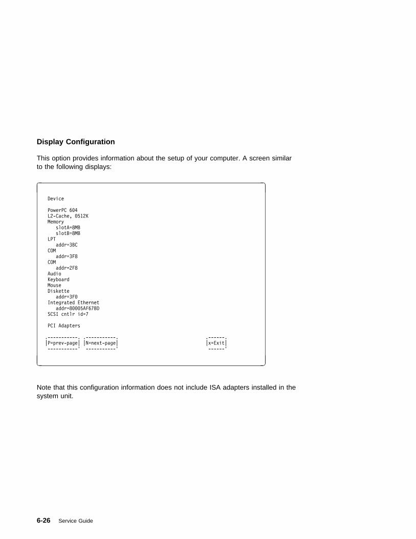
Display Configuration
This option provides information about the setup of your computer. A screen similarto the following displays:
� �
Device
PowerPC 6�4
L2-Cache, �512K
Memory
slotA=8MB
slotB=8MB
LPT
addr=3BC
COM
addr=3F8
COM
addr=2F8
Audio
Keyboard
Mouse
Diskette
addr=3F�
Integrated Ethernet
addr=8���5AF67BD
SCSI cntlr id=7
PCI Adapters
.-----------. .-----------. .------.
|P=prev-page| |N=next-page| |x=Exit|
-----------' -----------' ------'
1 2
Note that this configuration information does not include ISA adapters installed in thesystem unit.
6-26 Service Guide

Select Boot Devices
This selection enables you to view and change the custom boot list, which is thesequence of devices read at startup time.
� �Select Boot Devices
1. Display Current Settings
2. Restore Default Settings
3. Configure 1st Boot Device
4. Configure 2nd Boot Device
5. Configure 3rd Boot Device
6. Configure 4th Boot Device
.------.
|X=Exit|
------'
====>
1 2
Selecting the Display Current Settings option lists the current order of devices in theboot list. The following screen shows an example of this display.
� �Current Boot Sequence
1. Diskette
2. Ethernet (Integrated)
3. SCSI CD-ROM id=3 (slot=1)
4. SCSI 5��MB Hard Disk id=6 (slot=1)
.------.
|X=Exit|
------'
===>
1 2
Chapter 6. System Management Services 6-27
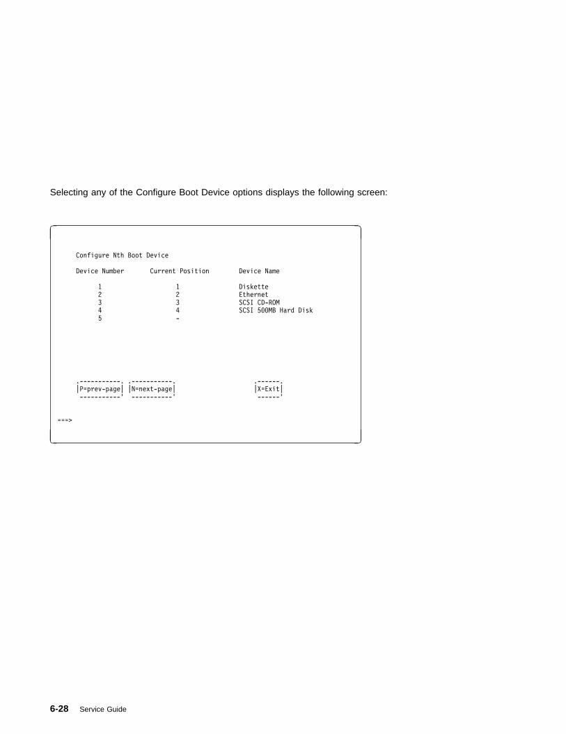
Selecting any of the Configure Boot Device options displays the following screen:
� �
Configure Nth Boot Device
Device Number Current Position Device Name
1 1 Diskette
2 2 Ethernet
3 3 SCSI CD-ROM
4 4 SCSI 5��MB Hard Disk
5 -
.-----------. .-----------. .------.
|P=prev-page| |N=next-page| |X=Exit|
-----------' -----------' ------'
===>
1 2
6-28 Service Guide

Utilities
The Utilities screen enables you to select from the following system managementtools.
The following screen appears if you DO NOT have a service processor installed inyour system:
� �
Utilities
1. Set Password and Unattended Start Mode
2. Audio <ON>
3. Display Error Log
4. Remote Initial Program Load Setup
5. Change SCSI id
6. Update System Firmware
7. Select Console
.------.
|X=Exit|
------'
===>
1 2
The following screen appears if you have a service processor installed in yoursystem:
� �
Utilities
1. Set Password and Unattended Start Mode
2. Audio <ON>
3. Display Error Log
4. Remote Initial Program Load Setup
5. Change SCSI id
6. Update System Firmware
7. Update Service Processor
8. Select Console
.------.
|X=Exit|
------'
===>
1 2
Chapter 6. System Management Services 6-29

Set Password and Unattended Start Mode: Entering this selection permitsaccess to the following options:
� �
Password Utilities
1. Set Power On Password
2. Remove Power On Password
3. Unattended Start Mode <OFF>
4. Set Privileged-Access Password
5. Remove Privileged-Access Password
.------.
|X=Exit|
------'
===>
1 2
Set Power On Password: Setting a power-on password helps protect informationstored in your computer. You can use any combination of up to eight characters(A–Z, a–z, and 0–9) for your password. The password you type is not displayed onthe screen. Press Enter when you are finished; you are required to type thepassword again for verification.
If you previously had set a power-on password and wanted to remove it, selectRemove Power-On Password.
Note: If you forget your password, you must shut down the computer and removethe battery for at least 30 seconds to disable the password. See “Battery” onpage 7-46 for details.
A password can be set only after the system is turned off and on again.
6-30 Service Guide

Set Privileged-Access Password: The privileged-access password protects againstthe unauthorized starting of the system programs.
If you previously had set a privileged-access password and want to remove it, selectRemove Privileged-Access Password.
Note: If you forget your password, you must shut down the computer and removethe battery for at least 30 seconds to disable the password. See “Battery” onpage 7-46 for details.
Audio: Selecting this utility turns on or off the system tones heard at power-ontime.
Remote Initial Program Load Setup: This option allows you to enable and setup the remote startup capability of your computer. First, you are asked to specify thenetwork parameters.
� �
Network Parameters
1. IP Parameters
2. Adapter Parameters
3. Ping
.------.
|X=Exit|
------'
===>
1 2
Note: Some applications may require that IP addresses contain leading zeroes fornumbers less than 100. For example, 129.132.4.20 may need to be entered as123.132.004.020.
Chapter 6. System Management Services 6-31

Selecting the IP Parameters option displays the following screen.
� �IP Parameters
1. Client IP Address ���.���.���.���
2. Server IP Address ���.���.���.���
3. Gateway IP Address ���.���.���.���
4. Subnet Mask ���.���.���.���
.------.
|X=Exit|
------'
===>
1 2
Selecting the Adapter Parameters option allows you to view an adapter's hardwareaddress as well as configure network adapters that require setup.
� �
Adapter Parameters
Device HW Address
1. 3Com,3C9�5 8���5AFC67BD
2. Token-Ring 8���32E54A12
.------.
|X=Exit|
------'
1 2
6-32 Service Guide
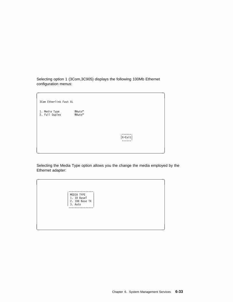
Selecting option 1 (3Com,3C905) displays the following 100Mb Ethernetconfiguration menus:
� �
3Com Etherlink Fast XL
1. Media Type fflAuto“
2. Full Duplex fflAuto“
.------.
|X=Exit|
------'
1 2
Selecting the Media Type option allows you the change the media employed by theEthernet adapter:
� �
.----------------.
| MEDIA TYPE |
| 1. 1� BaseT |
| 2. 1�� Base TX |
| 3. Auto |
----------------'
1 2
Chapter 6. System Management Services 6-33

Selecting the Full Duplex option allows you to change how the Ethernet adaptercommunicates with the network:
� �
.----------------.
| Full Duplex |
| 1. Yes |
| 2. No |
| 3. Auto |
----------------'
1 2
Ping, the last option available from the Network Parameters menu, allows you to testa connection to a remote system unit. After selecting the Ping option, you mustchoose which adapter communicates with the remote system.
� �
Interface
1. Ethernet (Integrated)
2. Token Ring (Slot=3)
===>
1 2
6-34 Service Guide

After choosing which adapter to use to ping the remote system, you must provide theaddresses needed to communicate with the remote system.
� �Ping
1. Client IP Address 129.132.4.2�
2. Server IP Address 129.132.4.1�
3. Gateway IP Address 129.132.4.3�
4. Subnet Mask 255.255.255.�
.---------. .------.
|E=Execute| |X=Exit|
---------' ------'
===>
1 2
Display Error Log: A screen similar to the following is displayed when you selectthis option. Here, you can view or clear your computer's error log.
� �
.----------------------------------------------------------.
| Error Log |
| |
| Date Time ErrorCode Location |
| Entry 1. 96/�4/�1 12:13:22 25A8��11 ��-�� |
| Entry 2. no error logged |
----------------------------------------------------------'
.-----------------. .------.
|C=Clear Error Log| |X=Exit|
-----------------' ------'
1 2
Change SCSI ID: This option allows you to view and change the addresses of theSCSI controllers attached to you computer.
Chapter 6. System Management Services 6-35
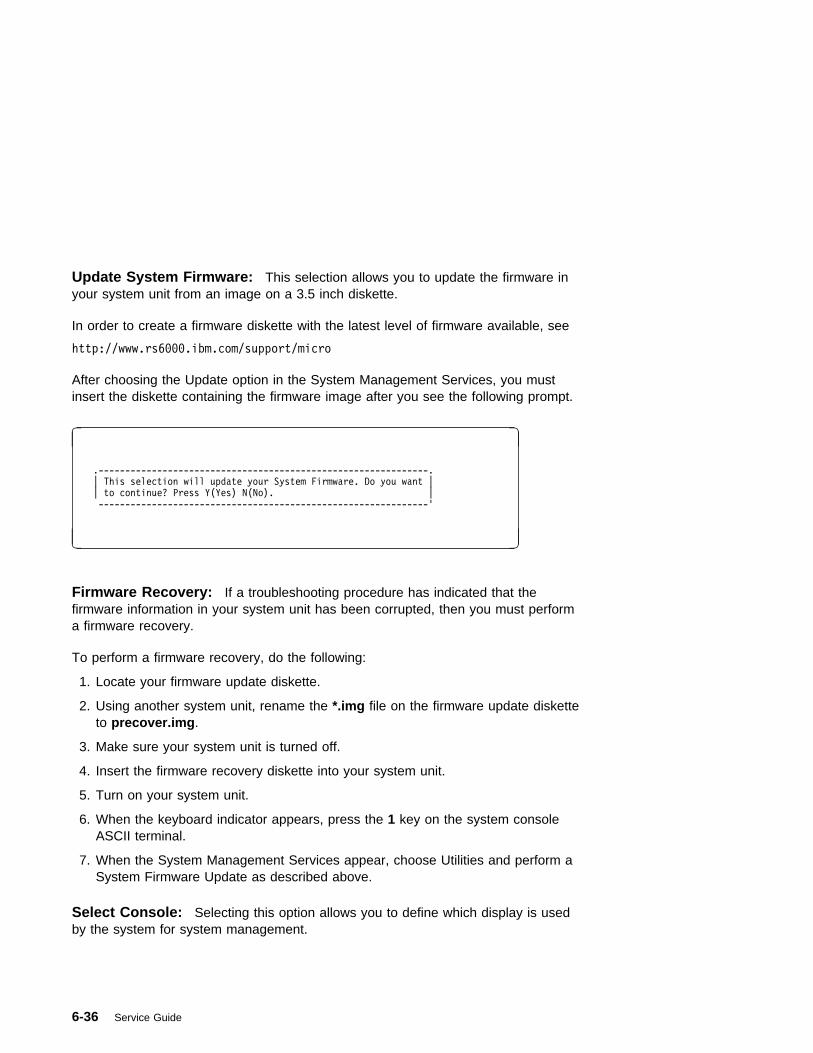
Update System Firmware: This selection allows you to update the firmware inyour system unit from an image on a 3.5 inch diskette.
In order to create a firmware diskette with the latest level of firmware available, see
http://www.rs6���.ibm.com/support/micro
After choosing the Update option in the System Management Services, you mustinsert the diskette containing the firmware image after you see the following prompt.
� �
.--------------------------------------------------------------.
| This selection will update your System Firmware. Do you want |
| to continue? Press Y(Yes) N(No). |
--------------------------------------------------------------'
1 2
Firmware Recovery: If a troubleshooting procedure has indicated that thefirmware information in your system unit has been corrupted, then you must performa firmware recovery.
To perform a firmware recovery, do the following:
1. Locate your firmware update diskette.
2. Using another system unit, rename the *.img file on the firmware update disketteto precover.img.
3. Make sure your system unit is turned off.
4. Insert the firmware recovery diskette into your system unit.
5. Turn on your system unit.
6. When the keyboard indicator appears, press the 1 key on the system consoleASCII terminal.
7. When the System Management Services appear, choose Utilities and perform aSystem Firmware Update as described above.
Select Console: Selecting this option allows you to define which display is usedby the system for system management.
6-36 Service Guide
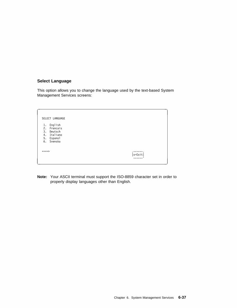
Select Language
This option allows you to change the language used by the text-based SystemManagement Services screens:
� �
SELECT LANGUAGE
1. English
2. Francais
3. Deutsch
4. Italiano
5. Espanol
6. Svenska
====> .------.
|x=Exit|
------'
1 2
Note: Your ASCII terminal must support the ISO-8859 character set in order toproperly display languages other than English.
Chapter 6. System Management Services 6-37

6-38 Service Guide
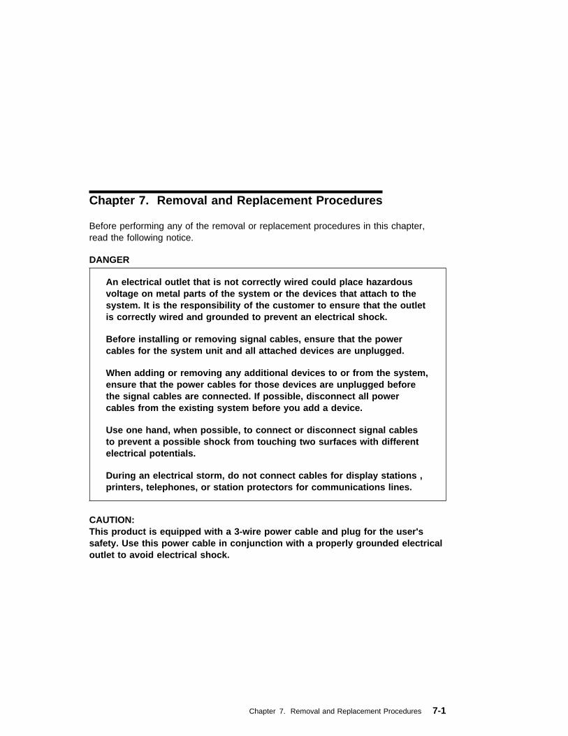
Chapter 7. Removal and Replacement Procedures
Before performing any of the removal or replacement procedures in this chapter,read the following notice.
DANGER
An electrical outlet that is not correctly wired could place hazardousvoltage on metal parts of the system or the devices that attach to thesystem. It is the responsibility of the customer to ensure that the outletis correctly wired and grounded to prevent an electrical shock.
Before installing or removing signal cables, ensure that the powercables for the system unit and all attached devices are unplugged.
When adding or removing any additional devices to or from the system,ensure that the power cables for those devices are unplugged beforethe signal cables are connected. If possible, disconnect all powercables from the existing system before you add a device.
Use one hand, when possible, to connect or disconnect signal cablesto prevent a possible shock from touching two surfaces with differentelectrical potentials.
During an electrical storm, do not connect cables for display stations ,printers, telephones, or station protectors for communications lines.
CAUTION:This product is equipped with a 3-wire power cable and plug for the user'ssafety. Use this power cable in conjunction with a properly grounded electricaloutlet to avoid electrical shock.
Chapter 7. Removal and Replacement Procedures 7-1
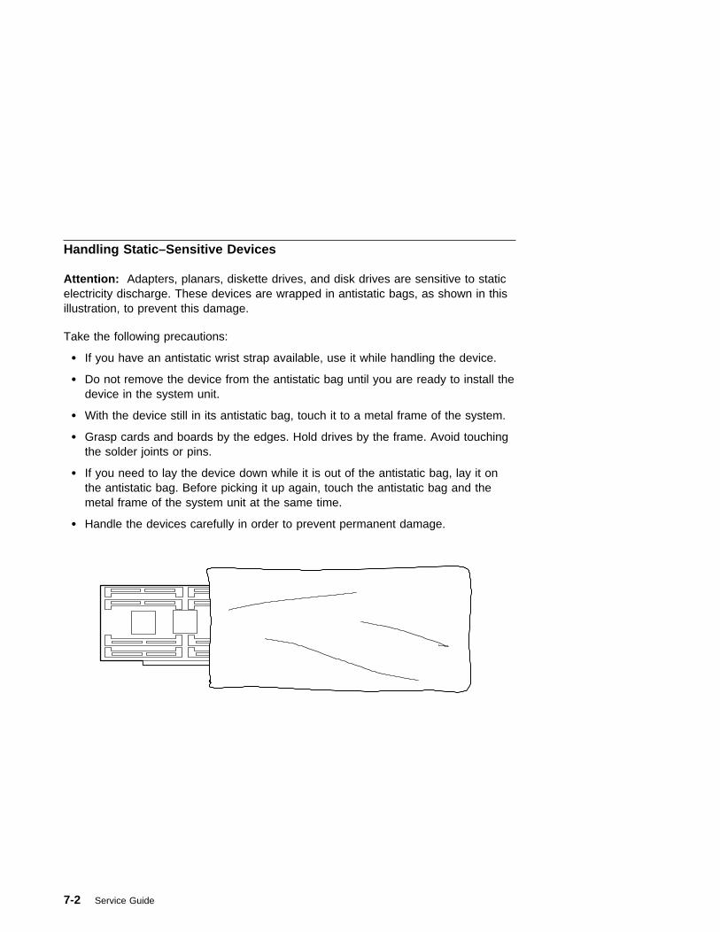
Handling Static–Sensitive Devices
Attention: Adapters, planars, diskette drives, and disk drives are sensitive to staticelectricity discharge. These devices are wrapped in antistatic bags, as shown in thisillustration, to prevent this damage.
Take the following precautions:
� If you have an antistatic wrist strap available, use it while handling the device.
� Do not remove the device from the antistatic bag until you are ready to install thedevice in the system unit.
� With the device still in its antistatic bag, touch it to a metal frame of the system.
� Grasp cards and boards by the edges. Hold drives by the frame. Avoid touchingthe solder joints or pins.
� If you need to lay the device down while it is out of the antistatic bag, lay it onthe antistatic bag. Before picking it up again, touch the antistatic bag and themetal frame of the system unit at the same time.
� Handle the devices carefully in order to prevent permanent damage.
7-2 Service Guide

Covers
Removal
1. Open the door.
Chapter 7. Removal and Replacement Procedures 7-3

2. Remove the door by carefully lifting it up and off the hinges. Store it in a safeplace.
3. Remove all media (diskettes, CDs, optical discs, or tapes) from drives; then turnthe power off to the system and all attached devices.
4. Shutdown the operating system.
5. Turn off power to the system and all attached options.
7-4 Service Guide
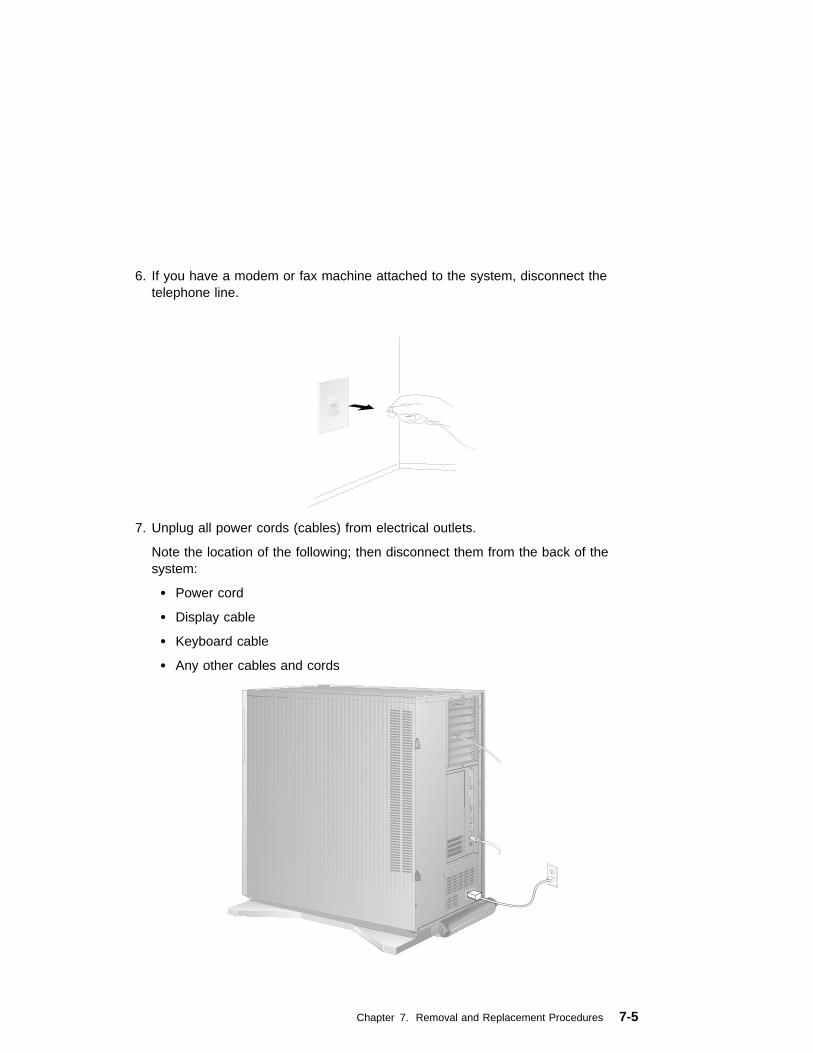
6. If you have a modem or fax machine attached to the system, disconnect thetelephone line.
7. Unplug all power cords (cables) from electrical outlets.
Note the location of the following; then disconnect them from the back of thesystem:
� Power cord
� Display cable
� Keyboard cable
� Any other cables and cords
Chapter 7. Removal and Replacement Procedures 7-5
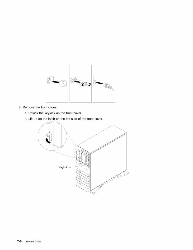
8. Remove the front cover:
a. Unlock the keylock on the front cover.
b. Lift up on the latch on the left side of the front cover.
7-6 Service Guide
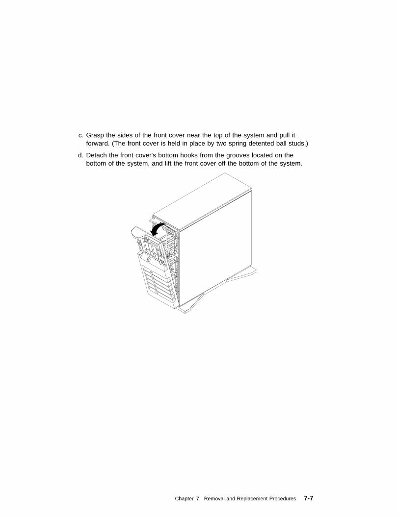
c. Grasp the sides of the front cover near the top of the system and pull itforward. (The front cover is held in place by two spring detented ball studs.)
d. Detach the front cover's bottom hooks from the grooves located on thebottom of the system, and lift the front cover off the bottom of the system.
Chapter 7. Removal and Replacement Procedures 7-7

9. Remove the side cover:
a. Open the side cover to a 90 degree angle.
b. Remove the cover by carefully lifting it up and off the hinges. Store it in asafe place.
7-8 Service Guide
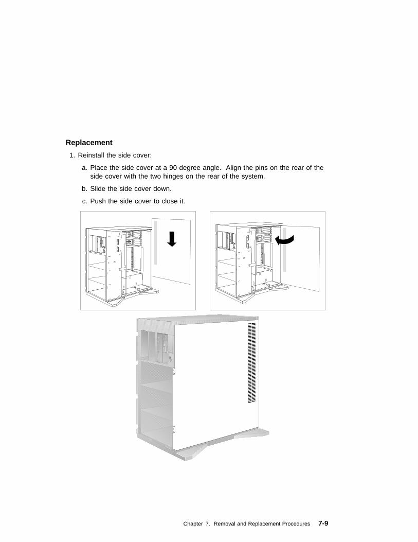
Replacement
1. Reinstall the side cover:
a. Place the side cover at a 90 degree angle. Align the pins on the rear of theside cover with the two hinges on the rear of the system.
b. Slide the side cover down.
c. Push the side cover to close it.
Chapter 7. Removal and Replacement Procedures 7-9
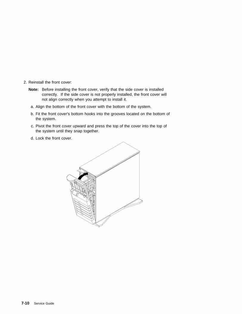
2. Reinstall the front cover:
Note: Before installing the front cover, verify that the side cover is installedcorrectly. If the side cover is not properly installed, the front cover willnot align correctly when you attempt to install it.
a. Align the bottom of the front cover with the bottom of the system.
b. Fit the front cover's bottom hooks into the grooves located on the bottom ofthe system.
c. Pivot the front cover upward and press the top of the cover into the top ofthe system until they snap together.
d. Lock the front cover.
7-10 Service Guide
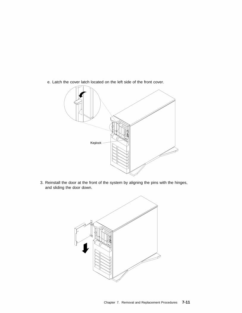
e. Latch the cover latch located on the left side of the front cover.
3. Reinstall the door at the front of the system by aligning the pins with the hinges,and sliding the door down.
Chapter 7. Removal and Replacement Procedures 7-11

4. Close the door.
7-12 Service Guide

Power Supply
DANGER
Do not attempt to open the covers of the power supply. Power suppliesare not serviceable and are to be replaced as a unit.
Note: The power supply assembly may consist of one or two power supplies, abase supply and an optional supply. You can replace either supply separately.
Removal
1. If you have not already done so, remove the covers as described in “Covers” onpage 7-3.
2. If your system has only a base supply installed, complete steps 1 through 7 only.If your system has both the base and optional supplies installed, complete all ofthe removal steps.
3. Disconnect the four cables from system board connectors J1, J16, J17 and J30.
Chapter 7. Removal and Replacement Procedures 7-13
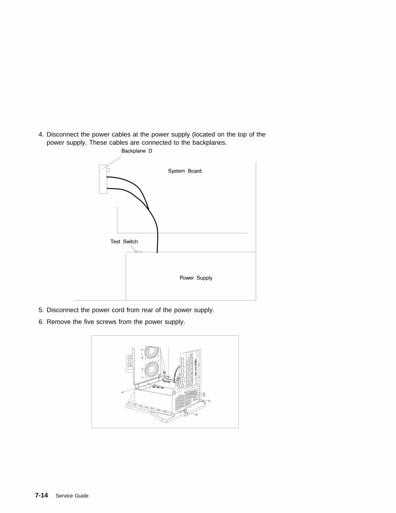
4. Disconnect the power cables at the power supply (located on the top of thepower supply. These cables are connected to the backplanes.
5. Disconnect the power cord from rear of the power supply.
6. Remove the five screws from the power supply.
7-14 Service Guide
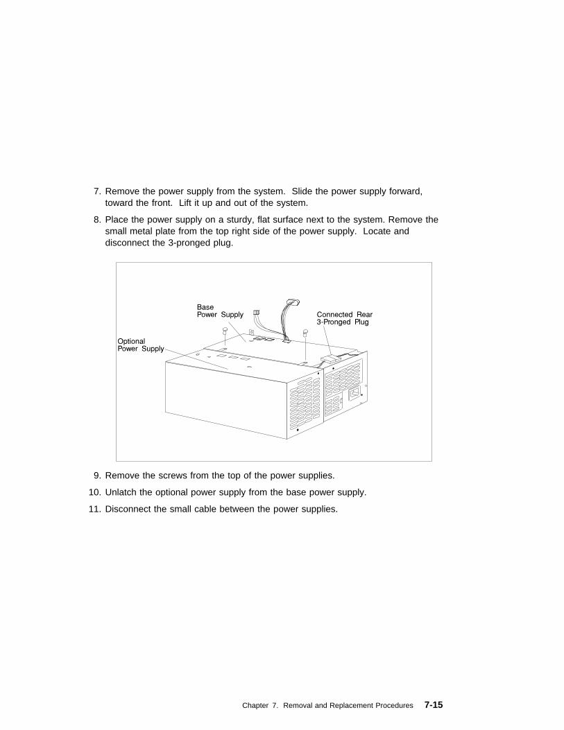
7. Remove the power supply from the system. Slide the power supply forward,toward the front. Lift it up and out of the system.
8. Place the power supply on a sturdy, flat surface next to the system. Remove thesmall metal plate from the top right side of the power supply. Locate anddisconnect the 3-pronged plug.
9. Remove the screws from the top of the power supplies.
10. Unlatch the optional power supply from the base power supply.
11. Disconnect the small cable between the power supplies.
Chapter 7. Removal and Replacement Procedures 7-15

Replacement
1. If your system had only the base supply installed, go to step 9 on page 7-22. Ifyour system has both the base and optional supplies installed, go to the nextstep.
2. Replace the defective power supply.
3. Rotate the base power supply so that the latching hooks are facing up.
7-16 Service Guide

4. Locate the optional power supply.
5. Connect the lower front cable from the optional power supply to the left lowerside of the base power supply.
Attention: Push the excess cable into the side cavity of the optional powersupply. This prevents the cable from pinching and allows the two power suppliesto connect properly.
Chapter 7. Removal and Replacement Procedures 7-17

6. Connect the power supplies to each other by sliding the latching hooks on theoptional power supply into the matching slots on the base power supply.
7-18 Service Guide

Rotate the two power supplies back to their normal position for installing into thebottom of the system.
a. Install the screws connecting the power supplies as shown.
b. Connect the rear three-prong plug from the optional power supply to thebase power supply.
Chapter 7. Removal and Replacement Procedures 7-19

7. Install the small metal plate that you removed in step 8 on page 7-15.
7-20 Service Guide
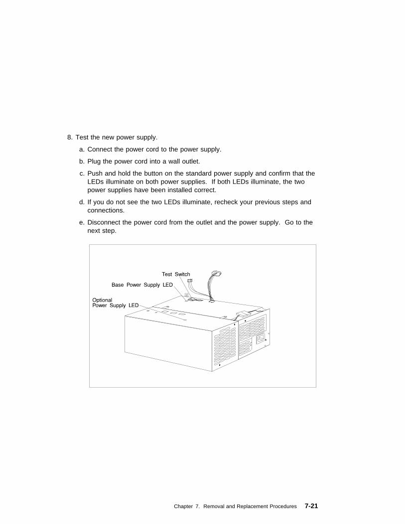
8. Test the new power supply.
a. Connect the power cord to the power supply.
b. Plug the power cord into a wall outlet.
c. Push and hold the button on the standard power supply and confirm that theLEDs illuminate on both power supplies. If both LEDs illuminate, the twopower supplies have been installed correct.
d. If you do not see the two LEDs illuminate, recheck your previous steps andconnections.
e. Disconnect the power cord from the outlet and the power supply. Go to thenext step.
Chapter 7. Removal and Replacement Procedures 7-21

9. Place the power supply assembly in the bottom of the system. Slide the powersupply backward, toward the rear of the system.
10. Secure the power-supply assembly by installing the five screws that you removedin step 6 on page 7-14.
11. Reconnect the cables.
a. Reconnect the power supply cables between the power supplies andbackplanes that were removed in step 4 on page 7-14.
7-22 Service Guide
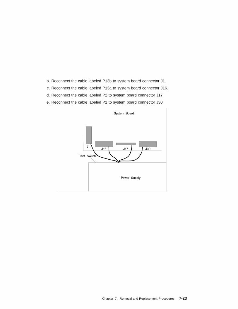
b. Reconnect the cable labeled P13b to system board connector J1.
c. Reconnect the cable labeled P13a to system board connector J16.
d. Reconnect the cable labeled P2 to system board connector J17.
e. Reconnect the cable labeled P1 to system board connector J30.
Chapter 7. Removal and Replacement Procedures 7-23

CD-ROM Drive, Tape Drive, Diskette Drive
CAUTION:Do not open the drive; no user adjustments or serviceable parts are inside.
Removal
1. If you have not already done so, remove the covers as described in “Covers” onpage 7-3.
2. Disconnect the power and signal cables to the drive you are removing.
3. Slide the drive forward to remove.
Replacement
Replace in reverse order.
7-24 Service Guide
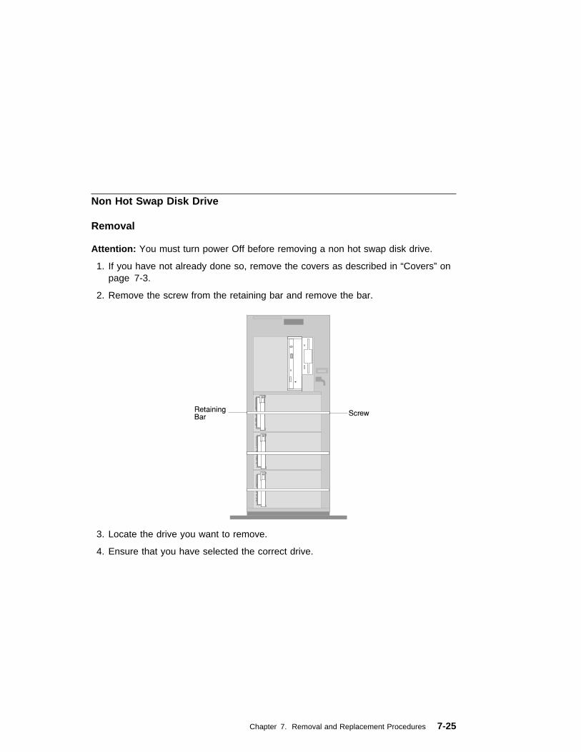
Non Hot Swap Disk Drive
Removal
Attention: You must turn power Off before removing a non hot swap disk drive.
1. If you have not already done so, remove the covers as described in “Covers” onpage 7-3.
2. Remove the screw from the retaining bar and remove the bar.
3. Locate the drive you want to remove.
4. Ensure that you have selected the correct drive.
Chapter 7. Removal and Replacement Procedures 7-25

5. Unlock the drive by turning the carrier latch 90 degrees clockwise to the openposition.
6. Disconnect the drive from the connector on the backplane, by grasping thehandle on the drive tray and carefully pulling the drive out of the system. Storethe drive in a safe place.
Attention: Handle the disk drive with care as it is very fragile and can be easilydamaged if exposed to shock, ESD, or rough handling.
7-26 Service Guide

Replacement
Attention: Handle the disk drive with care as it is very fragile and can be easilydamaged if exposed to shock, electrostatic discharge, or rough handling.
Attaching SCSI address jumpers on the drive rather than using the automatic IDfurnished by the backplane is not advised. Attaching jumpers can cause serviceproblems, multiple drives at the same address, or confusion locating the correctdrive.
1. Rotate the carrier latch to the open position.
2. Position the drive carrier assembly vertically, with the connector facing the rear ofthe system.
Chapter 7. Removal and Replacement Procedures 7-27

3. Align the side of the carrier with the raised guides on the bottom of the bay.
4. Slide the carrier into the bay gently to keep from damaging the disk drive. Slidethe carrier to the rear of the bay until it stops.
5. Move the carrier latch to the locked position. If the carrier will not lock, check thatthe drive carrier is fully seated in the backplane. When the drive carrier is fullyseated and power is turned on, the green LED on the drive carrier will illuminate.
7-28 Service Guide

Backplane
Removal
1. If you have not already done so, remove the covers as described in “Covers” onpage 7-3.
2. Remove the screw from the backplane.
3. Slide the backplane out to gain cable access.
4. Disconnect the signal cable and the power cable from the backplane.
5. Remove the backplane.
Chapter 7. Removal and Replacement Procedures 7-29
Replacement
Check the jumpers on the new backplane for proper setting. The jumpers should beset the same as on the backplane you removed.
Replace in reverse order.
7-30 Service Guide
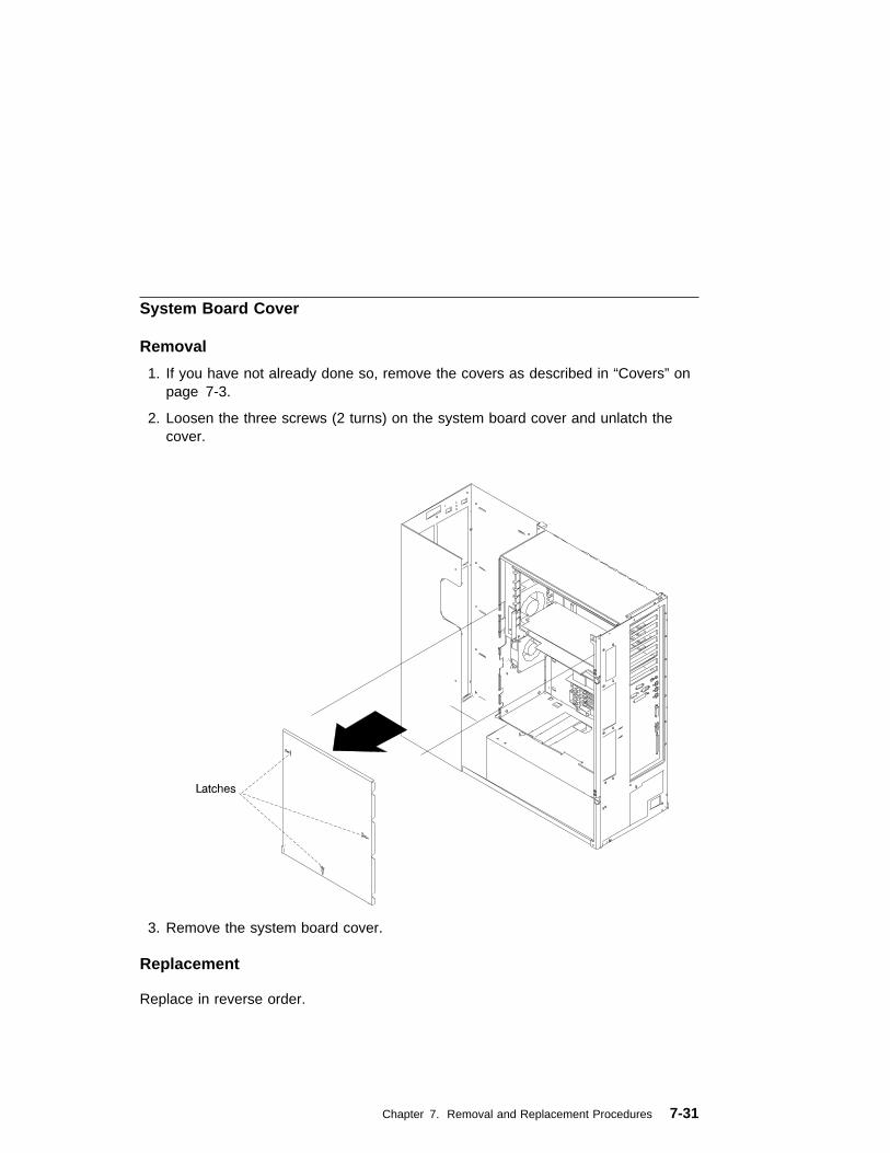
System Board Cover
Removal
1. If you have not already done so, remove the covers as described in “Covers” onpage 7-3.
2. Loosen the three screws (2 turns) on the system board cover and unlatch thecover.
3. Remove the system board cover.
Replacement
Replace in reverse order.
Chapter 7. Removal and Replacement Procedures 7-31
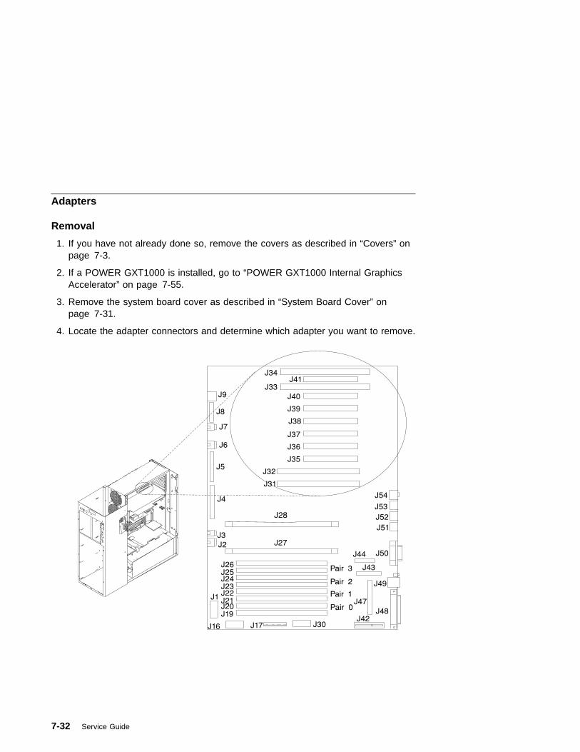
Adapters
Removal
1. If you have not already done so, remove the covers as described in “Covers” onpage 7-3.
2. If a POWER GXT1000 is installed, go to “POWER GXT1000 Internal GraphicsAccelerator” on page 7-55.
3. Remove the system board cover as described in “System Board Cover” onpage 7-31.
4. Locate the adapter connectors and determine which adapter you want to remove.
7-32 Service Guide
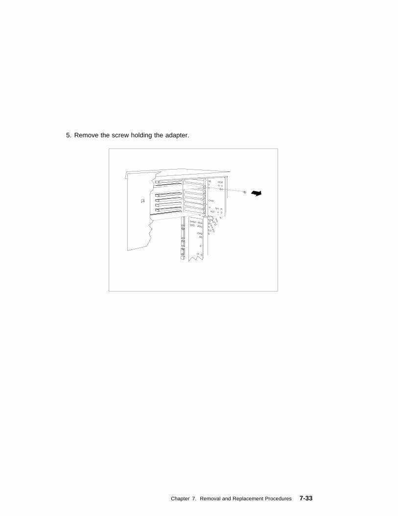
5. Remove the screw holding the adapter.
Chapter 7. Removal and Replacement Procedures 7-33
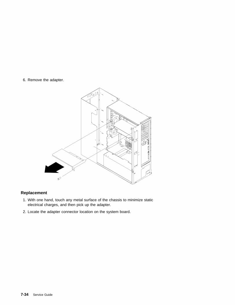
6. Remove the adapter.
Replacement
1. With one hand, touch any metal surface of the chassis to minimize staticelectrical charges, and then pick up the adapter.
2. Locate the adapter connector location on the system board.
7-34 Service Guide
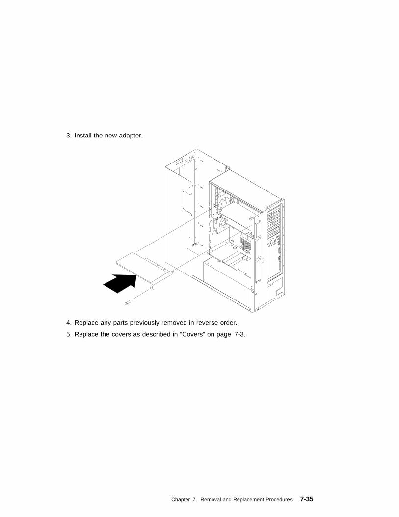
3. Install the new adapter.
4. Replace any parts previously removed in reverse order.
5. Replace the covers as described in “Covers” on page 7-3.
Chapter 7. Removal and Replacement Procedures 7-35
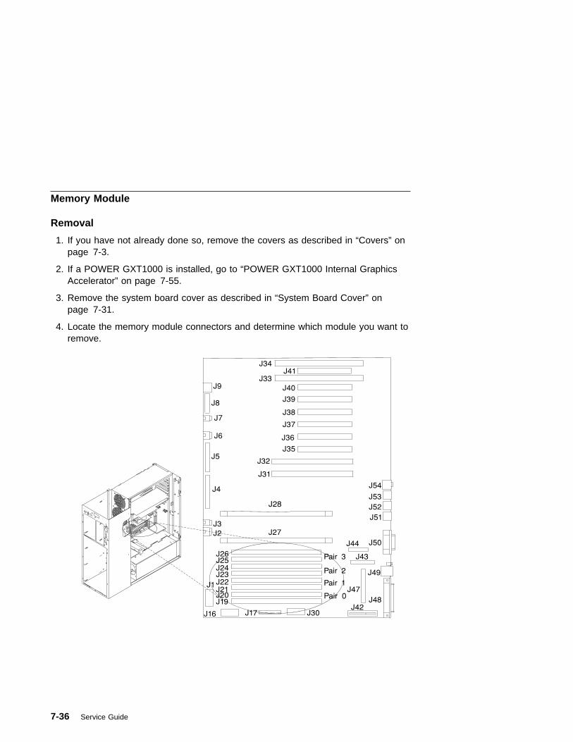
Memory Module
Removal
1. If you have not already done so, remove the covers as described in “Covers” onpage 7-3.
2. If a POWER GXT1000 is installed, go to “POWER GXT1000 Internal GraphicsAccelerator” on page 7-55.
3. Remove the system board cover as described in “System Board Cover” onpage 7-31.
4. Locate the memory module connectors and determine which module you want toremove.
7-36 Service Guide

5. Remove the memory module by pushing the tabs out on the memory connectors.
Push Locking TabsOut to Release MemoryModule
1
2
1
Replacement
1. With one hand, touch any metal surface of the chassis to minimize staticelectrical charges, and then pick up a memory module.
2. Locate the memory module connector location on the system board.
3. Install the new memory module.
4. Replace the covers as described in “Covers” on page 7-3.
Chapter 7. Removal and Replacement Procedures 7-37

System Board
1. If you have not already done so, remove the covers as described in “Covers” onpage 7-3.
2. If a POWER GXT1000 is installed, go to “POWER GXT1000 Internal GraphicsAccelerator” on page 7-55.
3. Remove the system board cover as described in “System Board Cover” onpage 7-31.
Note: Adapter cables should be labeled to insure correct installation of cablesto adapters slots. Rearranging the order of the SCSI slots to the disk drive bankswill cause errors.
7-38 Service Guide

4. Remove all adapter cards.
Chapter 7. Removal and Replacement Procedures 7-39
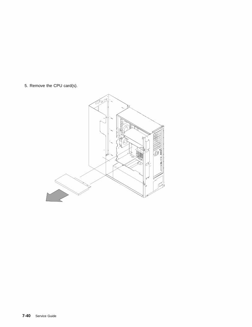
5. Remove the CPU card(s).
7-40 Service Guide

6. Remove all memory modules.
7. Disconnect all cables from the connectors on the system board.
8. Remove eight screws connecting the system board to the rear of the system.Note that the screws in the SCSI connector are black.
9. Remove 13 screws from the system board.
10. Remove system board.
Replacement
Replace in reverse order.
Note: Be sure to install the two black screws in the SCSI connector.
Verify that the security jumpers (J46) are in the correct position (same as thereplaced system board.
Chapter 7. Removal and Replacement Procedures 7-41
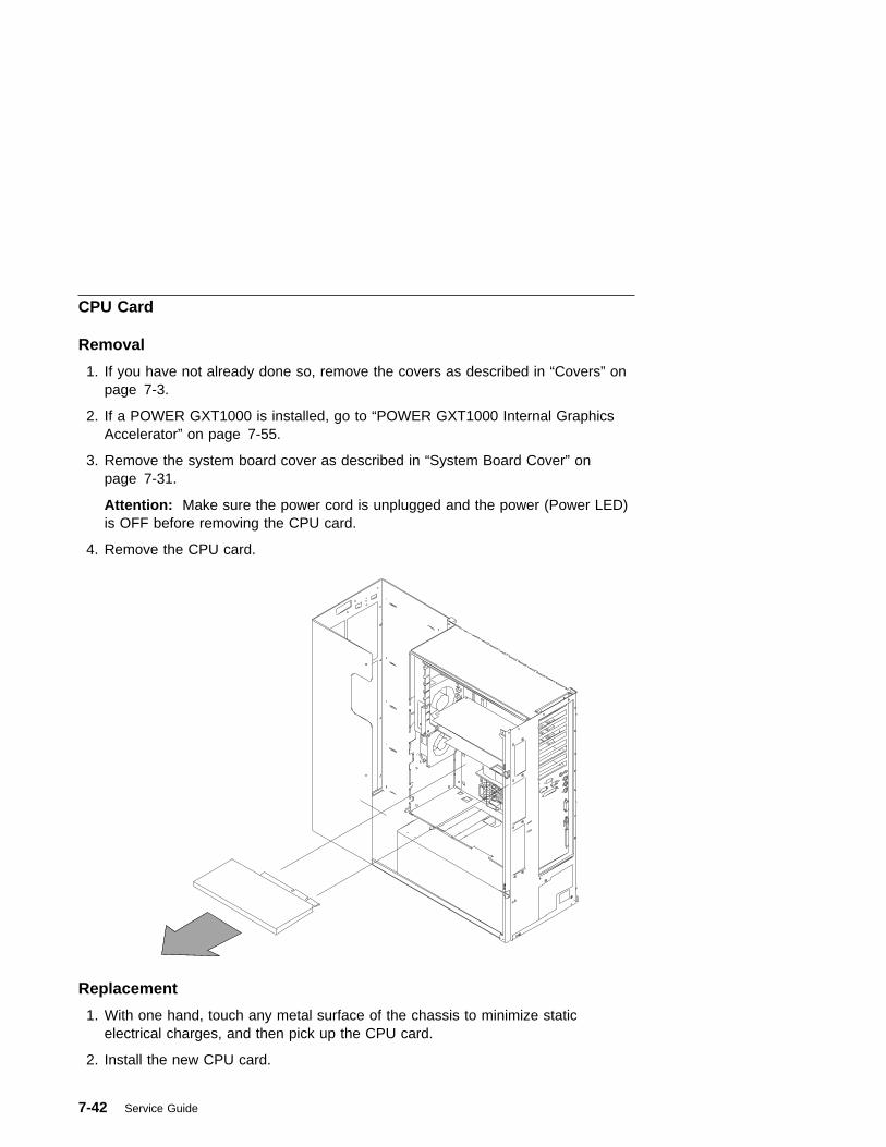
CPU Card
Removal
1. If you have not already done so, remove the covers as described in “Covers” onpage 7-3.
2. If a POWER GXT1000 is installed, go to “POWER GXT1000 Internal GraphicsAccelerator” on page 7-55.
3. Remove the system board cover as described in “System Board Cover” onpage 7-31.
Attention: Make sure the power cord is unplugged and the power (Power LED)is OFF before removing the CPU card.
4. Remove the CPU card.
Replacement
1. With one hand, touch any metal surface of the chassis to minimize staticelectrical charges, and then pick up the CPU card.
2. Install the new CPU card.
7-42 Service Guide
3. Replace any parts previously removed in reverse order.
4. Replace the covers as described in “Covers” on page 7-3.
Chapter 7. Removal and Replacement Procedures 7-43
Service Processor
Removal
1. If you have not already done so, remove the covers as described in “Covers” onpage 7-3.
2. If a POWER GXT1000 is installed, go to “POWER GXT1000 Internal GraphicsAccelerator” on page 7-55.
3. Remove the system board cover as described in “System Board Cover” onpage 7-31.
Attention: Make sure the power cord is unplugged and the power LED is OFFbefore removing the service processor.
4. Remove the service processor.
7-44 Service Guide

Replacement
To replace the service processor, perform the removal steps in the reverse order.
Chapter 7. Removal and Replacement Procedures 7-45
Battery
CAUTION:A lithium battery can cause fire, explosion, or a severe burn. Do not recharge,disassemble, heat above 100°C (212°F), solder directly to the cell, incinerate, orexpose cell contents to water. Keep away from children. Replace only with thepart number specified for your system. Use of another battery may present arisk of fire or explosion.
The battery connector is polarized; do not attempt to reverse polarity.
Dispose of the battery according to local regulations.
Removal
1. If you have not already done so, remove the covers as described in “Covers” onpage 7-3.
2. If a POWER GXT1000 is installed, go to “POWER GXT1000 Internal GraphicsAccelerator” on page 7-55.
3. Remove the system board cover as described in “System Board Cover” onpage 7-31. unlatch the cover.
4. Locate the battery on the system board.
7-46 Service Guide

Chapter 7. Removal and Replacement Procedures 7-47
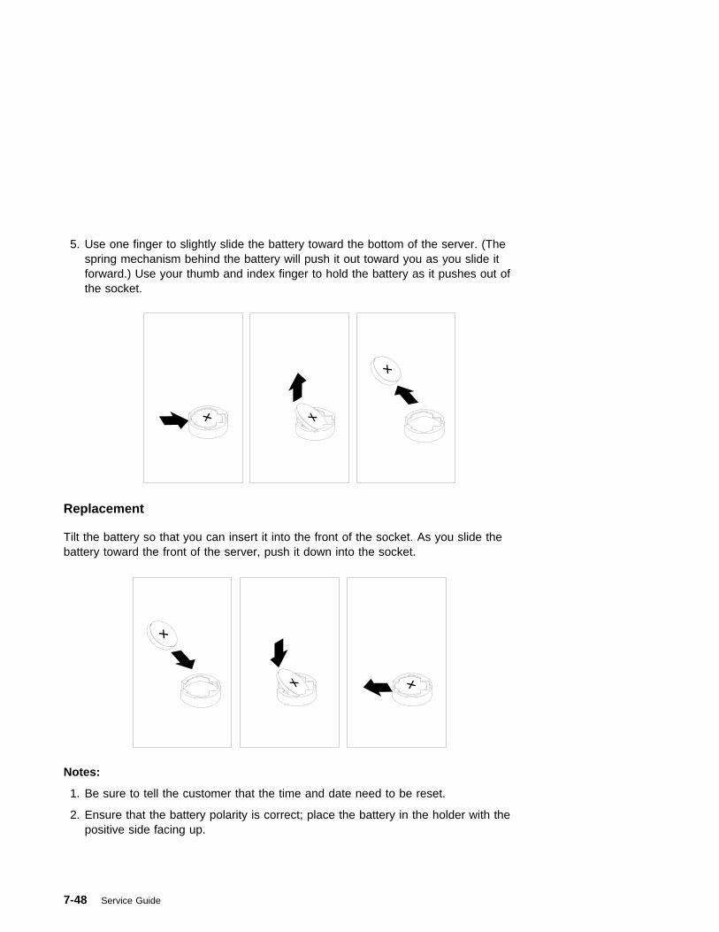
5. Use one finger to slightly slide the battery toward the bottom of the server. (Thespring mechanism behind the battery will push it out toward you as you slide itforward.) Use your thumb and index finger to hold the battery as it pushes out ofthe socket.
Replacement
Tilt the battery so that you can insert it into the front of the socket. As you slide thebattery toward the front of the server, push it down into the socket.
Notes:
1. Be sure to tell the customer that the time and date need to be reset.
2. Ensure that the battery polarity is correct; place the battery in the holder with thepositive side facing up.
7-48 Service Guide

Fans
Removal
1. Do the cover removal procedure in “Covers” on page 7-3.
2. If removing one of the two upper fans, remove the three screws from the adaptercard bracket and remove the bracket.
3. Disconnect the fan cable from the system board.
4. Pull the shock mounts out of their mounting holes.
5. Remove the fan.
Chapter 7. Removal and Replacement Procedures 7-49

Replacement
Replace in reverse order.
7-50 Service Guide

Operator Panel Display
Removal
1. If you have not already done so, remove the front covers as described in“Covers” on page 7-3.
2. Press the snap in detent on the right side of the display card mounting bracketand remove the display card.
3. Rotate the display forward and out of the mounting bracket.
4. Disconnect the display cable from the connector on the display assembly.
Replacement
Replace in reverse order. Ensure that the grounding clips located inside themounting bracket are not bent or damaged and that they are positioned correctly.
Chapter 7. Removal and Replacement Procedures 7-51
Operator Panel Control Assembly
Removal
1. Do the cover removal procedure in “Covers” on page 7-3.
2. Remove the assembly by compressing the spring clip at the top and bottom ofthe assembly and pulling out toward the rear of the system.
3. Unplug the LCD cable from the assembly.
4. Unplug the audio cable from the system board.
5. Unplug the control card cable from the system board.
Replacement
Replace in reverse order.
7-52 Service Guide

Serial Cable
Removal
1. If you have not already done so, remove the covers as described in “Covers” onpage 7-3.
2. Remove the serial cable from the system board connector J44.
3. Remove the four screws from the S1 and S2 connectors on the rear of thesystem.
Replacement
Replace in reverse order.
Connect the serial cables as follows:
P1 J44 (system board)P2 S1 connectorP3 S2 connector
Chapter 7. Removal and Replacement Procedures 7-53
Parallel Cable
Removal
1. If you have not already done so, remove the covers as described in “Covers” onpage 7-3.
2. Remove the parallel cable from the system board connector J43.
3. Remove the two screws from the parallel connector on the rear of the system.
Replacement
Replace in reverse order.
7-54 Service Guide

POWER GXT1000 Internal Graphics Accelerator
Attention: Your POWER GXT1000 enclosure is very sensitive. Handle it verycarefully.
Removal
1. If you have not already done so, remove the covers as described in “Covers” onpage 7-3.
2. Unplug the external cables attached.
Chapter 7. Removal and Replacement Procedures 7-55

3. Remove the four POWER GTX1000 mounting screws from the rear of thesystem. Place the screws in a safe place, you need them when you reinstall theenclosure.
7-56 Service Guide
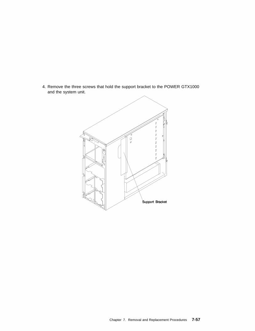
4. Remove the three screws that hold the support bracket to the POWER GTX1000and the system unit.
Chapter 7. Removal and Replacement Procedures 7-57
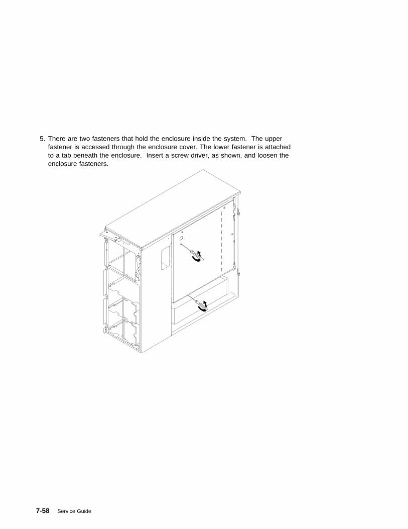
5. There are two fasteners that hold the enclosure inside the system. The upperfastener is accessed through the enclosure cover. The lower fastener is attachedto a tab beneath the enclosure. Insert a screw driver, as shown, and loosen theenclosure fasteners.
7-58 Service Guide
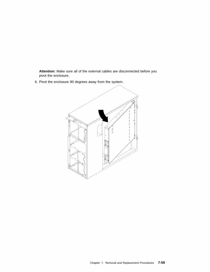
Attention: Make sure all of the external cables are disconnected before youpivot the enclosure.
6. Pivot the enclosure 90 degrees away from the system.
Chapter 7. Removal and Replacement Procedures 7-59

7. Disconnect cables that are attached to the bottom on the enclosure:
a. Disconnect the 2 fan cables.
b. Disconnect the 2 power supply cables.
8. The power supply cables are attached to the bottom on the enclosure.Disconnect the 2 power supply cables and the 2 fan cables.
7-60 Service Guide
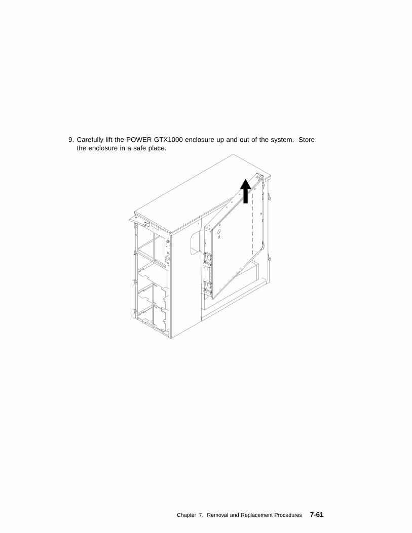
9. Carefully lift the POWER GTX1000 enclosure up and out of the system. Storethe enclosure in a safe place.
Chapter 7. Removal and Replacement Procedures 7-61
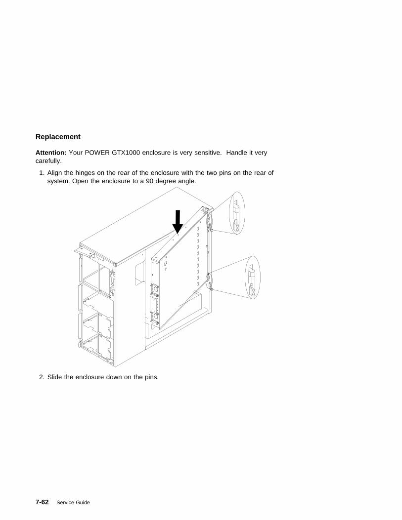
Replacement
Attention: Your POWER GTX1000 enclosure is very sensitive. Handle it verycarefully.
1. Align the hinges on the rear of the enclosure with the two pins on the rear ofsystem. Open the enclosure to a 90 degree angle.
2. Slide the enclosure down on the pins.
7-62 Service Guide
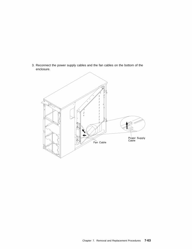
3. Reconnect the power supply cables and the fan cables on the bottom of theenclosure.
Chapter 7. Removal and Replacement Procedures 7-63

4. Carefully push the enclosure into the system.
7-64 Service Guide
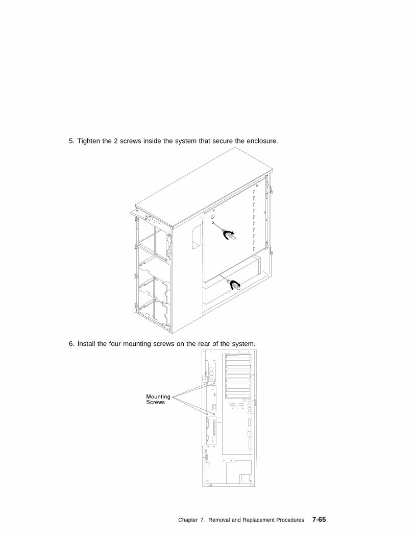
5. Tighten the 2 screws inside the system that secure the enclosure.
6. Install the four mounting screws on the rear of the system.
Chapter 7. Removal and Replacement Procedures 7-65
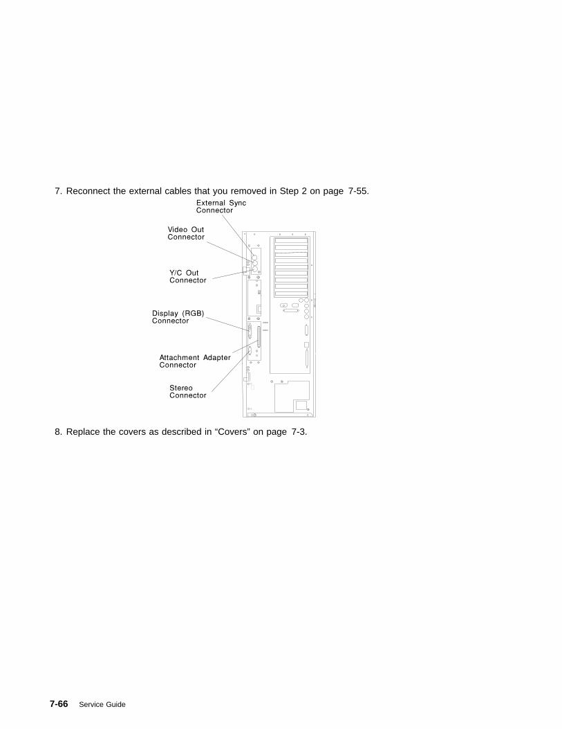
7. Reconnect the external cables that you removed in Step 2 on page 7-55.
8. Replace the covers as described in “Covers” on page 7-3.
7-66 Service Guide
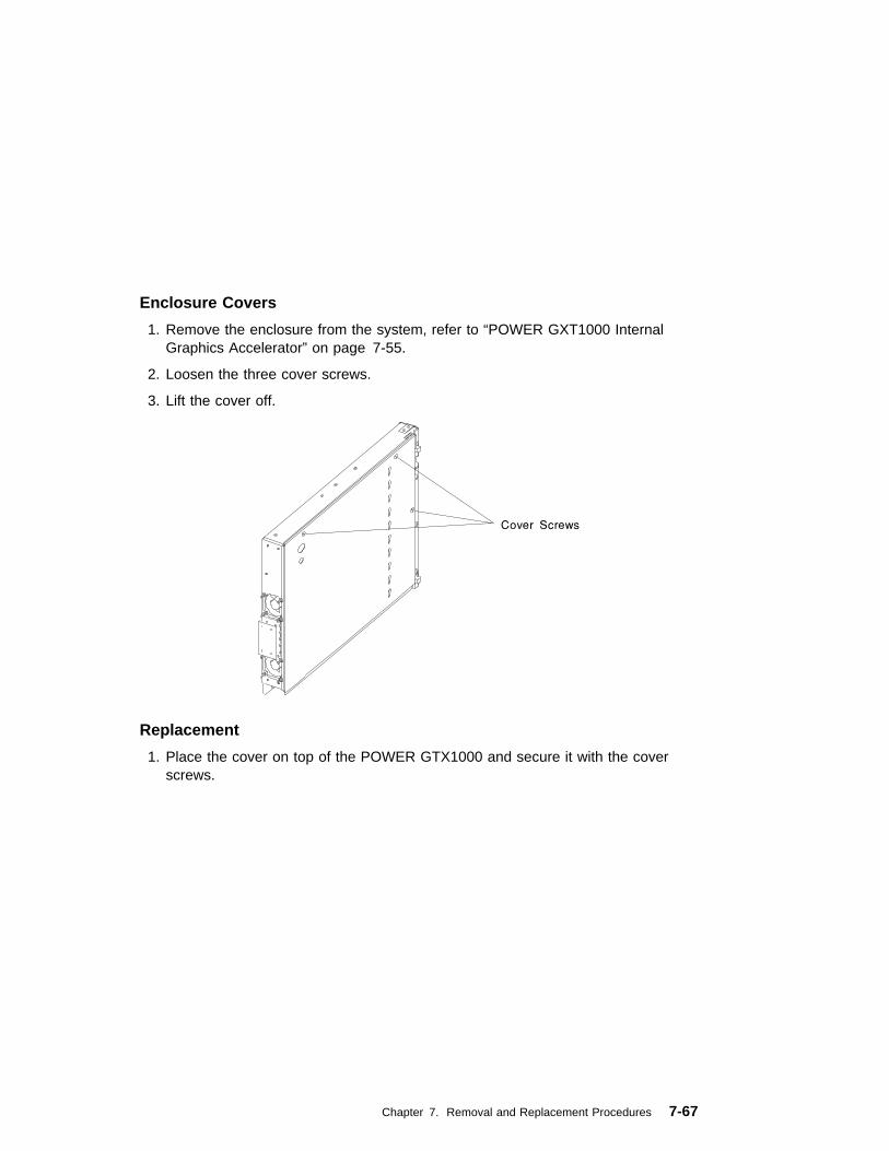
Enclosure Covers
1. Remove the enclosure from the system, refer to “POWER GXT1000 InternalGraphics Accelerator” on page 7-55.
2. Loosen the three cover screws.
3. Lift the cover off.
Replacement
1. Place the cover on top of the POWER GTX1000 and secure it with the coverscrews.
Chapter 7. Removal and Replacement Procedures 7-67

Fan Assembly
Removal
1. Remove the enclosure cover, refer to “Enclosure Covers” on page 7-67.
2. Remove the Cross-Over card and Shield. Grasp the cross-over at both sidesand pull toward the front of the enclosure.
3. Remove the five screws securing the fan assembly and lift out.
Replacement: Replace the fan assembly in reverse order.
7-68 Service Guide

Logic Boards and RSS Memory
Refer to “Handling Static–Sensitive Devices” on page 7-2 before removing orinstalling logic boards.
VOO Board
Removal
1. Remove the enclosure cover, refer to “Enclosure Covers” on page 7-67.
2. Remove the two VOO mounting screws securing it to the card cage assembly.
3. Remove the VOO/RSS cable from the VOO board. Squeeze both cable sideclips to release the cable from the board.
4. Pull the VOO board toward the front of the POWER GTX1000 to remove it fromthe card cage assembly.
Replacement: Replace the VOO board in reverse order.
Chapter 7. Removal and Replacement Procedures 7-69
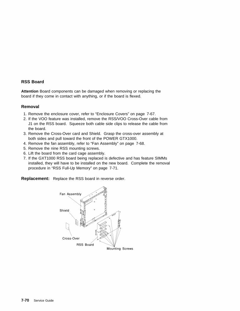
RSS Board
Attention Board components can be damaged when removing or replacing theboard if they come in contact with anything, or if the board is flexed.
Removal
1. Remove the enclosure cover, refer to “Enclosure Covers” on page 7-67.2. If the VOO feature was installed, remove the RSS/VOO Cross-Over cable from
J1 on the RSS board. Squeeze both cable side clips to release the cable fromthe board.
3. Remove the Cross-Over card and Shield. Grasp the cross-over assembly atboth sides and pull toward the front of the POWER GTX1000.
4. Remove the fan assembly, refer to “Fan Assembly” on page 7-68.5. Remove the nine RSS mounting screws.6. Lift the board from the card cage assembly.7. If the GXT1000 RSS board being replaced is defective and has feature SIMMs
installed, they will have to be installed on the new board. Complete the removalprocedure in “RSS Full-Up Memory” on page 7-71.
Replacement: Replace the RSS board in reverse order.
7-70 Service Guide
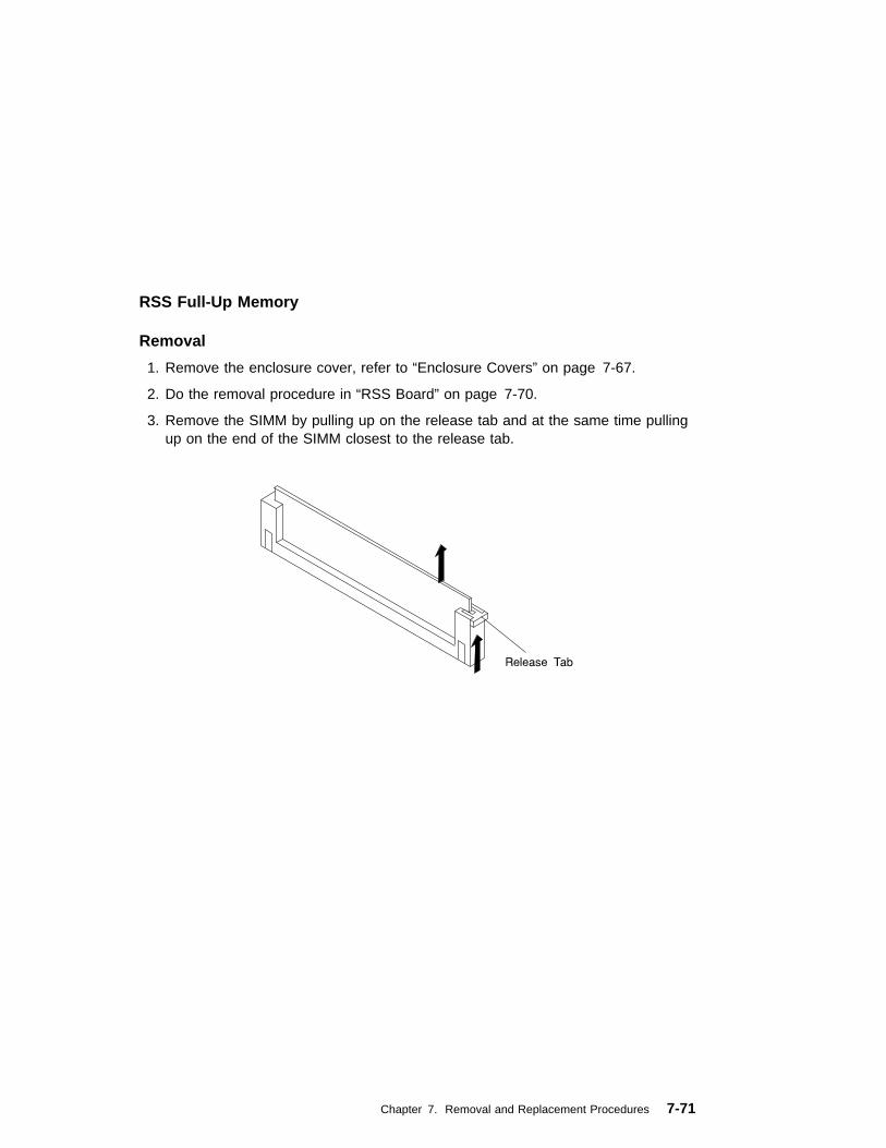
RSS Full-Up Memory
Removal
1. Remove the enclosure cover, refer to “Enclosure Covers” on page 7-67.
2. Do the removal procedure in “RSS Board” on page 7-70.
3. Remove the SIMM by pulling up on the release tab and at the same time pullingup on the end of the SIMM closest to the release tab.
Chapter 7. Removal and Replacement Procedures 7-71

Replacement
1. Ensure the RSS board is on a flat, level surface.
2. Install the SIMM with the notch closest to the release tab.
3. Push down on both ends of the SIMM until it is firmly seated in the socket.
4. Replace any components you removed in reverse order.
7-72 Service Guide
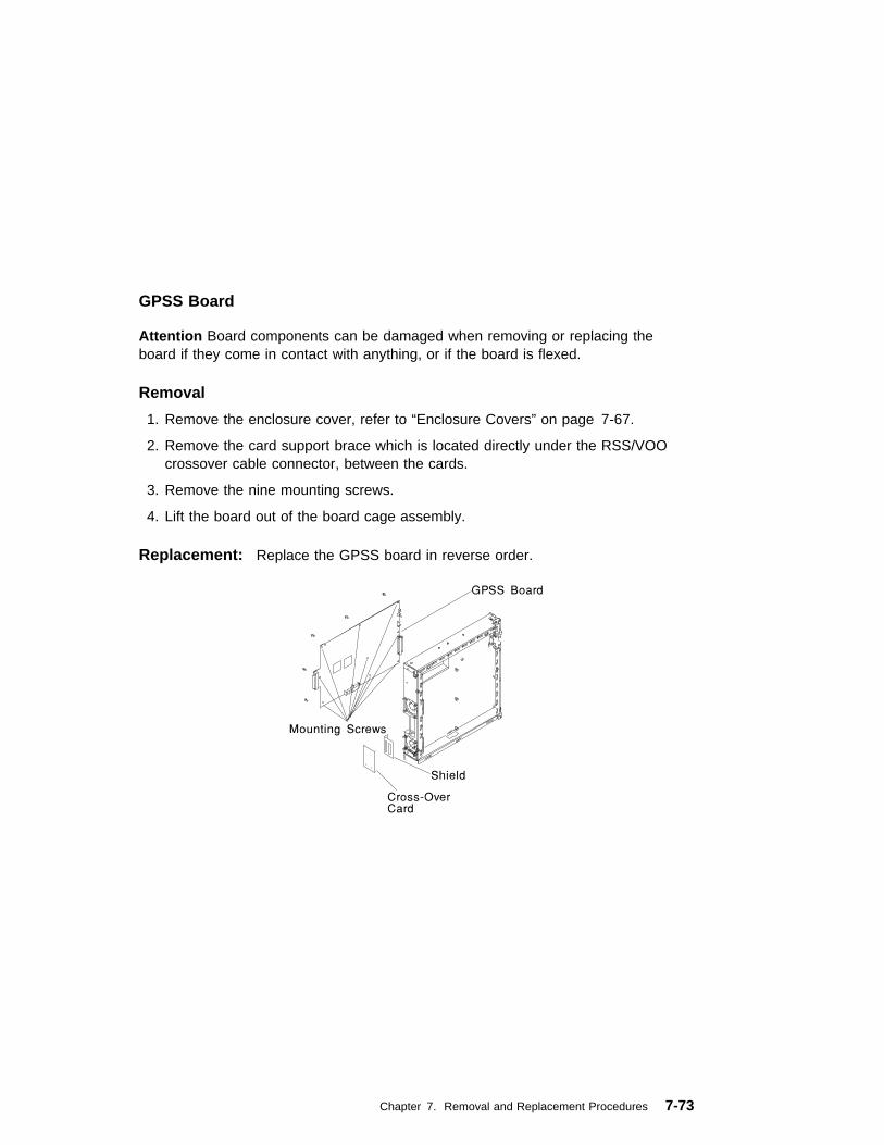
GPSS Board
Attention Board components can be damaged when removing or replacing theboard if they come in contact with anything, or if the board is flexed.
Removal
1. Remove the enclosure cover, refer to “Enclosure Covers” on page 7-67.
2. Remove the card support brace which is located directly under the RSS/VOOcrossover cable connector, between the cards.
3. Remove the nine mounting screws.
4. Lift the board out of the board cage assembly.
Replacement: Replace the GPSS board in reverse order.
Chapter 7. Removal and Replacement Procedures 7-73

7-74 Service Guide
Chapter 8. Parts Information
Chapter 8. Parts Information 8-1

8-2 Service Guide

Note: See RS/6000 Diagnostic Information for Multiple Bus Systems for partnumbers.
Index Part Number Units Per Description
1 93H8544 1 Chassis assembly (includes covers andside door)
2 73H0898 1 EMC clip3 82G3614 1 Display panel4 93H1816 1 Cable (Display)5 93H8494 1 Operator panel control assembly6 93H8652 1 System board7 06H7697 13 Standoff8 33F8354 1 Battery9 93H6280 1 Cable (EPOW)10 40H1424 2 Fan (#1 and #3)
40H1423 1 Fan (#2)40H1433 1 Fan (#4)
11 40H2247 1 Service processor12 42H2771 Up to 8 8MB memory module
42H2772 Up to 8 16MB memory module42H2773 Up to 8 32MB memory module42H2774 Up to 8 64MB memory module93H6821 Up to 8 128MB memory module
13 See note Up to 10 Adapter card14 11H7517 1 CPU card (166 Mhz)
93H5163 1 CPU card (233 Mhz)15 93H3144 1 EMC gasket (I/O connectors)16 93H3145 1 EMC gasket (Ext. SCSI connector)17 40H0114 1 SCSI backplane (Hot swap)
40H1432 1 SCSI backplane (Non hot swap)93H6321 1 SSA backplane
18 40H4937 1 System board cover19 40H5023 1 Base power supply (575 watts)
06H3237 1 Optional DASD power supply (220 watts)40H3137 1 Optional POWER GXT1000 power
supply (226 watts)20 40H4936 1 Adapter card bracket21 See note 1 CD-ROM drive22 11H8156 1 Pedestal and wheel23 73H1881 1 Front cover24 93H2490 1 Logo25 See Note 1 Diskette drive26 06H2792 1 Plate assembly27 40H4941 1 Bezel (Operator panel)28 See note Up to 2 Media device29 06H7946 1 Bracket (Display panel)30 See note Up to 18 Disk drive31 See note Up to 18 Disk drive carrier assembly
Chapter 8. Parts Information 8-3

Index Part Number Units Per Description
1 2596293 3 Cable clamp2 73H1894 1 Cable (diskette)3 93H3490 1 Cable (SCSI 4-drop)4 39H9994 1 Cable (Power 2-drop)5 82G4799 1 Cable (Serial)6 8185219 1 Cable (Parallel)7 93H3580 1 Cable (CD-ROM audio)
92F1294 A/R Screw (3.5 x 6)
8-4 Service Guide

Index Part Number Units Per Description
1 73H1960 1 Top Cover2 11H8490 1 RSS base memory
11H4436 1 RSS Full Memory (AG Option)3 73H1888 1 Base4 73H4034 1 GPSS Board5 73H1958 1 Fan Assembly6 73H1962 1 Shield7 40H3160 1 Cross-over Card8 32G1547 18 Mounting Screw9 33G3907 4 Mounting Screw10 92F1294 5 Mounting Screw11 73H1887 1 Attachment Adapter Signal Cable12 65G4887 1 VOO Board
Chapter 8. Parts Information 8-5

Index Part Number Units Per Description
1 82G3278 1 Keyboard, United States English 1391402 1 Keyboard, French 1393395 1 Keyboard, Italian 1391403 1 Keyboard, German/Austrian 1391406 1 Keyboard, United Kingdom English 1391405 1 Keyboard, Spanish 79F0167 1 Keyboard, Japanese 64F7707 1 Keyboard, Brazilian Portuguese 82G3279 1 Keyboard, Canadian French 1391526 1 Keyboard, Belgian French/Dutch 1391411 1 Keyboard, Finnish 1391407 1 Keyboard, Danish 1399583 1 Keyboard, Bulgarian 1395881 1 Keyboard, Swiss French 1385882 2 Keyboard, Swiss German 1391409 1 Keyboard, Norwegian 1391511 1 Keyboard, Dutch 1391410 1 Keyboard, Portuguese 1399046 1 Keyboard, Greek 1391408 1 Keyboard, Hebrew 1399581 1 Keyboard, Hungarian 1391407 1 Keyboard, Icelanic 1399580 1 Keyboard, Polish 1399582 1 Keyboard, Romanian 1399571 1 Keyboard, Slovakian 1399570 1 Keyboard, Czechoslovakian 1393286 1 Keyboard, Turkish (ID 179) 8125409 1 Keyboard, Turkish (ID 440) 8131596 1 Keyboard, Arabic 06H5286 1 Keyboard, Korean 1393990 1 Keyboard, Chinese 006H3048 1 Keyboard, United States (OEM)2 11H4878 1 Mouse, 3-button
8-6 Service Guide

Power Cables
1 2 3 4
5 6 7
8 9 10 11
Index Part Number Country
1 1838574 Bahamas, Barbados, Bolivia, Brazil, Canada, Costa Rica,Dominican Republic, El Salvador, Ecuador, Guatemala, Guyana,Haiti, Honduras, Jamaica, Japan, Netherlands Antilles, Panama,Peru, Philippines, Taiwan, Thailand, Trinidad, Tobago, U.S.A.(except Chicago), Venezuela
2 6952300 Bahamas, Barbados, Bermuda, Bolivia, Brazil, Canada, CaymanIslands, Colombia, Costa Rica, Dominican Republic, Ecuador, ElSalvador, Guatemala, Guyana, Haiti, Honduras, Jamaica, Japan,Korea (South), Mexico, Netherlands Antilles, Nicaragua, Panama,Peru, Philippines, Puerto Rico, Saudi Arabia, Suriname, Trinidad,Taiwan, U.S.A. (except Chicago), Venezuela
2 62X1045 Chicago, U.S.A.
3 6952311 Argentina, Australia, New Zealand
4 13F9979 Abu Dhabi, Austria, Belgium, Bulgaria, Botswana, Egypt, Finland,France, Germany, Greece, Iceland, Indonesia, Korea (South),Lebanon, Luxembourg, Macau, Netherlands, Norway, Portugal,Saudi Arabia, Spain, Sudan, Sweden, Turkey, Yugoslavia
5 13F9997 Denmark
6 14F0015 Bangladesh, Burma, Pakistan, South Africa, Sri Lanka
7 14F0033 Bahrain, Bermuda, Brunei, Channel Islands, Cyprus, Ghana,Hong Kong, India, Iraq, Ireland, Jordan, Kenya, Kuwait, Malawi,Malaysia, Nigeria, Oman, People's Republic of China, Qatar,Sierra Leone, Singapore, Tanzania, Uganda, United ArabEmirates (Dubai), United Kingdom, Zambia
Chapter 8. Parts Information 8-7

Index Part Number Country
8 14F0051 Liechtenstein, Switzerland
9 14F0069 Chile, Ethiopia, Italy
10 14F0087 Israel
11 6952291 Paraguay, Colombia, Uruguay
8-8 Service Guide

Appendix A. Service Processor Progress Codes
SSA Hot-Swap Disk Drive Reported Errors
The following progress codes may be displayed as the Service Processor isinitialized during system startup.
A0A Service Processor detected hardware error; attempting Call-out.
A01 Setting up default Service Processor values
A02 Service Processor configuring NVRAM parameters
A04 Service Processor detected environmental failure; attempting Call-out.
A05 Service Processor disconnecting modem
A07 Service Processor configuring modem
A08 Service Processor detected system firmware surveillance failure; attempting Call-out
A09 Service Processor detected operating system surveillance failure; attempting Call-out
Appendix A. Service Processor Progress Codes A-1

A-2 Service Guide
Index
Aabout this book xixadapter
POSTs (power-on self-tests) 3-2adapters
removal and replacement 7-32aids, diagnostic
adapter POSTs (power-onself-tests) 3-2
disk drive module POSTs (power-onself-tests) 3-1
SRNs (service requestnumbers) 3-3, 3-4
Bbackplane
removal and replacement 7-29battery
removal and replacement 7-46boot list 5-1
Ccables
power 1-13, 8-7CD-ROM drive
removal and replacement 7-24cfgmgr command 3-17commands
cfgmgr 3-17diag -a 3-11send diagnostic 3-1
configurationinvalid SSA loop 3-14
continuous failure 3-15
coversenclosure 7-67removal and replacement 7-3
CPU cardremoval and replacement 7-42
Ddefinition of FRU names used in the
SRN table 3-4devices, handling static–sensitive 7-2devices, startup 6-7diag -a command 3-11diagnostic aids
adapter POSTs (power-onself-tests) 3-2
disk drive module POSTs (power-onself-tests) 3-1
SRNs (service requestnumbers) 3-3, 3-4
diskformatting, incompatible with the
system 3-17disk drive module
POSTs (power-on self-tests) 3-1diskette drive
removal and replacement 7-24
Eentry point, MAPs 3-16EPROM (programmable read-only
memory) 3-2error
microcode and software 3-4error code to FRU index 4-1error codes
POST 4-1
Index X-1
errorsSSA Hot-Swap Disk Drive
reported A-1
Ffailure
continuous 3-15fans
POWER GTX1000 7-68removal and replacement 7-49
fragility of disk drive modules 3-1FRU
names used in the SRN table 3-4used in the SRN table 3-4
Gglossary of FRU names used in the
SRN table 3-4GPSS
removal and replacement 7-69,7-73
GPSS boardcomponents 1-5
Hhandling static–sensitive devices 7-2how to use MAPs 3-15
Iindex, error code to FRU 4-1inside view
logic boards 1-5invalid SSA loop configurations 3-14iso 9000 statement xix
L
laser safety information xviilocations
system board 1-8system unit 1-1
logic boardsGPSS 7-69locations 1-5RSS 7-69VOO 7-69
loopconfigurations, SSA, invalid 3-14
Mmaintenance analysis procedures
(MAPs) 2-1, 3-15minimum configuration Map 2-14power MAP 2-9problem determination MAP 2-5
MAPs (maintenance analysisprocedures)
starting 3-16using 3-15
memory moduleremoval and replacement 7-36
microcodesoftware errors 3-4
minimum configuration Map 2-14module, disk drive
power-on self-tests (POSTs) 3-1
Nnames used in the SRN table 3-4numbers, service request
description of 3-3software and microcode errors 3-4table 3-5
X-2 Service Guide
Ooperator panel 1-10operator panel control assembly
operator panel controlassembly 7-52
removal and replacement 7-52operator panel display
removal and replacement 7-51
Pparallel cable
removal and replacement 7-54parts information 8-1pdisk
with no associated hdisk 3-17POS (programmable option
select) 3-2POST error codes 4-1POSTs (power-on self-tests) 3-1power cables 1-13, 8-7POWER GTX1000 rear view 1-4power MAP 2-9power supply
removal and replacement 7-13power-on self-tests (POSTs) 3-1, 3-2preface xixproblem determination
POSTs, adapter 3-2POSTs, disk drive module 3-1SRNs (service request
numbers) 3-3problem determination MAP 2-5programmable option select
(POS) 3-2programmable read-only memory
(EPROM) 3-2progress codes, Service
Processor A-1
Rrelated publications xixremoval and replacement
covers 7-67fans 7-68GPSS 7-73logic boards 7-69memory, RSS 7-71non hot swap disk drive 7-25RSS 7-70VOO 7-69
removal and replacementprocedures 7-1
adapters 7-32backplane 7-29battery 7-46CD-ROM drive 7-24covers 7-3CPU card 7-42diskette drive 7-24fan 7-49memory module 7-36operator panel display 7-51parallel cable 7-54power supply 7-13serial cable 7-53service processor 7-44system board 7-38system board cover 7-31tape drive 7-24
RSSremoval and replacement 7-69,
7-70RSS board
components 1-6
Ssafety
electrical xv
Index X-3
safety notices xvsend diagnostic command 3-1sequence, startup 6-7serial cable
removal and replacement 7-53service inspection guide 1-14service processor 7-44
removal and replacement 7-44Service Processor progress codes A-1service request numbers (SRNs)
description of 3-3software and microcode errors 3-4table 3-5
software and microcode errors 3-4specifications, system unit 1-11SRNs (service request numbers) 3-3,
3-4, 3-5SSA (serial storage architecture)
loopconfigurations, invalid 3-14
SSA Hot-Swap Disk Drive reportederrors A-1
Start Up program 6-7starting
MAPs 3-16starting system programs 6-1, 6-24Sys Config program 6-4system board
removal and replacement 7-38system board cover
removal and replacement 7-31system board locations 1-8system programs 6-1
Start Up 6-7starting 6-1, 6-24Sys Config 6-4Utilities 6-9
system unit locations 1-1
Ttable
service request numbers(SRNs) 3-5
tape driveremoval and replacement 7-24
UUnplug all power cords (cables) 7-5using
MAPs 3-15SRN table 3-3
Utilities program 6-9
VVOO
removal and replacement 7-69VOO board
components 1-7
X-4 Service Guide

Index X-5
IBM
Part Number: 93H5364
Printed in the United States of Americaon recycled paper containing 10%recovered post-consumer fiber.
SA38-�515-�1
93H5364

+++ Duplicate ID CAUT3 was ignored on SPOT tag. (Page 7-1 File: A4AI3RRR)'.EDF@ID' WAS IMBEDDED AT LINE 100 OF '.EDFSPOT''.EDFSPOT' WAS IMBEDDED AT LINE 59 OF 'A4AI3RRR''A4AI3RRR' WAS IMBEDDED AT LINE 64 OF 'A4AI3BAS'STARTING PASS 2 OF 4.STARTING PASS 3 OF 4.STARTING PASS 4 OF 4.