service instructions aluminized steel heat exchanger, aluminized inshot burners, lonox, gas and...
TRANSCRIPT
RS6610003January 2007
ServiceInstructions
80% GDT, GMP, GMPE, GMPH,GMPV, GMT, GMTH, GPD90% GMNT, GMNTE, GMNV, GMPN, GSM,GSMS, GSU
This Forced Air Central Unit Design Complies WithRequirements Embodied in The American NationalStandard / National Standard of Canada Shown Below.
ANSI Z21.47•CSA-2.3 Central Furnaces
® This manual is to be used by qualified, professionally trained HVAC technicians only.Goodman does not assume any responsibility for property damage or personal injurydue to improper service procedures or services performed by an unqualified person.
Copyright © 2000-2007 Goodman Manufacturing Company, L.P.
Models listedon pages 4-6

2
IMPORTANT INFORMATIONPride and workmanship go into every product to provide our customers with quality products. It is possible, however,that during its lifetime a product may require service. Products should be serviced only by a qualified servicetechnician who is familiar with the safety procedures required in the repair and who is equipped with the proper tools,parts, testing instruments and the appropriate service manual. REVIEW ALL SERVICE INFORMATION IN THEAPPROPRIATE SERVICE MANUAL BEFORE BEGINNING REPAIRS.
IMPORTANT NOTICES FOR CONSUMERS AND SERVICERSRECOGNIZE SAFETY SYMBOLS, WORDS AND LABELS
IMPORTANT INFORMATION ........................... 2-3PRODUCT INFORMATION ........................... 4-12SPECIFICATIONS ....................................... 13-23DIMENSIONS ............................................... 24-27MAINTENANCE .................................................. 28
SERVICING .................................................. 30-56SERVICING TABLE OF CONTENTS ................ 32TROUBLESHOOTING ....................................... 46WIRING DIAGRAMS .................................... 58-77
WARNING
THIS UNIT SHOULD NOT BE CONNECTED TO, OR USED IN CONJUNCTION WITH, ANY DEVICES THAT ARE NOT DESIGN CERTIFIED FOR USE WITH THIS UNIT OR HAVE NOT BEENTESTED AND APPROVED BY GOODMAN. SERIOUS PROPERTY DAMAGE OR PERSONAL INJURY, REDUCED UNIT PERFORMANCE AND/OR HAZARDOUS CONDITIONS MAY RESULTFROM THE USE OF DEVICES THAT HAVE NOT BEEN APPROVED OR CERTIFED BY GOODMAN.
WARNING
TO PREVENT THE RISK OF PROPERTY DAMAGE, PERSONAL INJURY, OR DEATH,DO NOT STORE COMBUSTIBLE MATERIALS OR USE GASOLINE OR OTHERFLAMMABLE LIQUIDS OR VAPORS IN THE VICINITY OF THIS APPLIANCE.
WARNING
HIGH VOLTAGEDISCONNECT ALL POWER BEFORE SERVICING OR INSTALLING THIS UNIT. MULTIPLE POWER SOURCES MAY BE PRESENT. FAILURETO DO SO MAY CAUSE PROPERTY DAMAGE, PERSONAL INJURY OR DEATH.
WARNING
GOODMAN WILL NOT BE RESPONSIBLE FOR ANY INJURY OR PROPERTY DAMAGE ARISING FROM IMPROPER SERVICE OR SERVICE PROCEDURES.IF YOU INSTALL OR PERFORM SERVICE ON THIS UNIT, YOU ASSUME RESPONSIBILITY FOR ANY PERSONAL INJURY OR PROPERTY DAMAGE WHICHMAY RESULT. MANY JURISDICTIONS REQUIRE A LICENSE TO INSTALL OR SERVICE HEATING AND AIR CONDITIONING EQUIPMENT.
TABLE OF CONTENTS

3
To locate an authorized servicer, please consult your telephone book or the dealer from whom you purchased thisproduct. For further assistance, please contact:
CONSUMER INFORMATION LINEGOODMAN® BRAND PRODUCTS
TOLL FREE 1-877-254-4729 (U.S. only)email us at: [email protected]
fax us at: (731) 856-1821(Not a technical assistance line for dealers.)
Outside the U.S., call 1-713-861-2500.(Not a technical assistance line for dealers.) Your telephone company will bill you for the call.
IMPORTANT INFORMATION
WARNING
IF THE INFORMATION IN THESE INSTRUCTIONS IS NOT FOLLOWED EXACTLY, AFIRE OR EXPLOSION MAY RESULT CAUSING PROPERTY DAMAGE, PERSONALINJURY OR LOSS OF LIFE.
– DO NOT STORE OR USE GASOLINE OR OTHER FLAMMABLE VAPORS AND
LIQUIDS IN THE VICINITY OF THIS OR ANY OTHER APPLIANCE.
– WHAT TO DO IF YOU SMELL GAS:
• DO NOT TRY TO LIGHT ANY APPLIANCE.
• DO NOT TOUCH ANY ELECTRICAL SWITCH; DO NOT USE ANY
PHONE IN YOUR BUILDING.
• IMMEDIATELY CALL YOUR GAS SUPPLIER FROM A NEIGHBOR’S
PHONE. FOLLOW THE GAS SUPPLIER’S INSTRUCTIONS.
• IF YOU CANNOT REACH YOUR GAS SUPPLIER, CALL THE FIRE
DEPARTMENT.– INSTALLATION AND SERVICE MUST BE PERFORMED BY A QUALIFIED INSTALLER,
SERVICE AGENCY OR THE GAS SUPPLIER.
WARNING
SHOULD OVERHEATING OCCUR OR THE GAS SUPPLY FAIL TO SHUT OFF, TURN
OFF THE MANUAL GAS SHUTOFF VALVE EXTERNAL TO THE FURNACE BEFORE
TURNING OFF THE ELECTRICAL SUPPLY.
CARBON MONOXIDE POISONING HAZARD
-
Special Warning for Installation of Furnace or Air Handling Units inEnclosed Areas such as Garages, Utility Rooms or Parking Areas
Carbon monoxide producing devices (such as an automobile, spaceheater, gas water heater, etc.) should not be operated in enclosed areassuch as unventilated garages, utility rooms or parking areas because ofthe danger of carbon monoxide (CO) poisoning resulting from the exhaustemissions. If a furnace or air handler is installed in an enclosed area suchas a garage, utility room or parking area and a carbon monoxide producingdevice is operated therein, there must be adequate, direct outsideventilation.
This ventilation is necessary to avoid the danger of CO poisoning whichcan occur if a carbon monoxide producing device continues to operate inthe enclosed area. Carbon monoxide emissions can be (re)circulatedthroughout the structure if the furnace or air handler is operating in anymode.
CO can cause serious illness including permanent brain damage or death.
B10259-216
4
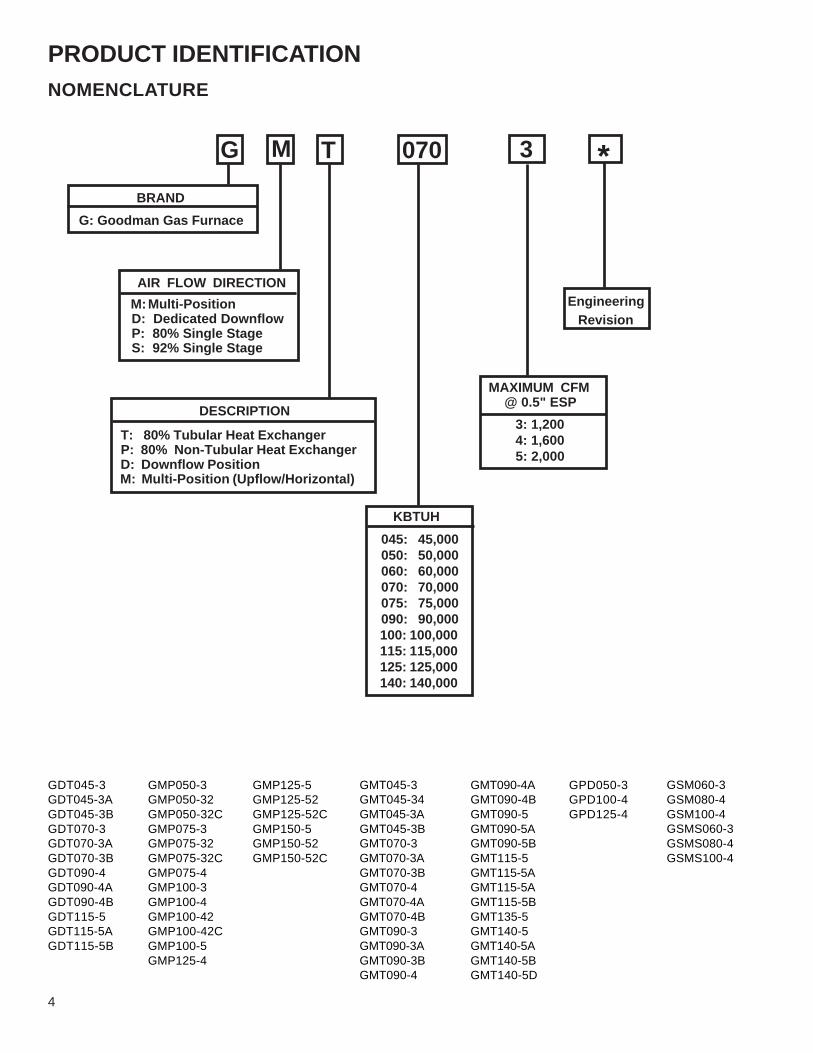
PRODUCT IDENTIFICATIONNOMENCLATURE
Engineering Revision
BRAND G: Goodman Gas Furnace
AIR FLOW DIRECTION
DESCRIPTION
T: 80% Tubular Heat Exchanger P: 80% Non-Tubular Heat Exchanger D: Downflow Position M: Multi-Position (Upflow/Horizontal)
G M T 3 * 070
MAXIMUM CFM @ 0.5" ESP 3: 1,200 4: 1,600 5: 2,000
KBTUH
GMT045-3GMT045-34GMT045-3AGMT045-3BGMT070-3GMT070-3AGMT070-3BGMT070-4GMT070-4AGMT070-4BGMT090-3GMT090-3AGMT090-3BGMT090-4
GMT090-4AGMT090-4BGMT090-5GMT090-5AGMT090-5BGMT115-5GMT115-5AGMT115-5AGMT115-5BGMT135-5GMT140-5GMT140-5AGMT140-5BGMT140-5D
GDT045-3GDT045-3AGDT045-3BGDT070-3GDT070-3AGDT070-3BGDT090-4GDT090-4AGDT090-4BGDT115-5GDT115-5AGDT115-5B
GMP050-3GMP050-32GMP050-32CGMP075-3GMP075-32GMP075-32CGMP075-4GMP100-3GMP100-4GMP100-42GMP100-42CGMP100-5GMP125-4
GMP125-5GMP125-52GMP125-52CGMP150-5GMP150-52GMP150-52C
GPD050-3GPD100-4GPD125-4
GSM060-3GSM080-4GSM100-4GSMS060-3GSMS080-4GSMS100-4
M: Multi-Position D: Dedicated Downflow P: 80% Single Stage S: 92% Single Stage
045: 45,000 050: 50,000 060: 60,000 070: 70,000 075: 75,000 090: 90,000 100: 100,000 115: 115,000 125: 125,000 140: 140,000

PRODUCT IDENTIFICATION
5
NOMENCLATURE
BRAND G: Goodman Gas Furnace
AIR FLOW DIRECTION M: Multi-Position D: Dedicated Downflow
DESCRIPTION
T: 80% Tubular Heat Exchanger P: 80% Non-Tubular Heat Exchanger
G M P
KBTUH
045: 45,000 070: 70,000 075: 75,000 090: 90,000 100: 100,000 115: 115,000 125: 125,000 140: 140,000
Engineering Revision
3 * 070
MAXIMUM CFM @ 0.5" ESP
BLOWER TYPE
V: Variable Speed - Single Stage E: Variable Speed - Two Stage H: High Air Flow
V
GMPV075-1.5GMPV075-3GMPV100-3GMPV100-5GMPV125-3GMPV125-5
GMPE075-3GMPE075-3AGMPE100-4GMPE100-4AGMPE125-5GMPE125-5A
GMTH045-3GMTH045-3AGMTH045-3BGMTH070-4GMTH070-4AGMTH070-4BGMTH090-5GMTH090-5BGMTH115-5
GMPH050-3GMPH075-4GMPH080-5GMPH120-5
3: 1,200 4: 1,600 5: 2,000

6
PRODUCT IDENTIFICATIONNOMENCLATURE
BRAND G: Goodman Gas Furnace
AIR FLOW DIRECTION
M: Upflow/Horizontal P: Position N: 92.6% Condensing
G M P
KBTUH
Engineering Revision
3 * 070
MAXIMUM CFM @ 0.5" ESP
N: 90% Condensing Furnace S: Single Stage Operation T: Single Stage - Tubular Heat Exchanger TE: Two-stage/Variable Speed - Tubular Heat Exchanger
N
GMPN040-3GMPN060-3GMPN080-4GMPN100-4GMPN120-5
GMNT040-3GMNT040-3BGMNT045-3BGMNT060-3GMNT060-3BGMNT080-4GMNT080-4BGMNT090-5AGMNT100-4GMNT100-4BGMNT120-5GMNT120-5BGMNT120-5D
GSMS060-3GSMS080-4GSMS100-4
GMNTE060-3GMNTE080-4GMNTE100-4GMNTE120-5
M: Multi-Position D: Dedicated Downflow S: 90+ Condensing Furnace
DESCRIPTION
BLOWER TYPE
3: 1,200 4: 1,600 5: 2,000
040: 40,000 060: 60,000 080: 80,000 100: 100,000 120: 120,000

PRODUCT IDENTIFICATION
7
Model # Description
GDT
80% AFUE. Downflow application, single stage, induced draft motor, psc multi-speed motor, integrated control module with diagnostics, hot surface ignition system, multiple roll out switches, pressure switches, aluminized tubular steel heat exchanger, aluminized inshot burners.
GMT
80% AFUE. Multi-position (Upflow, Horizontal Left or Right), single stage, induced draft motor, psc multi-speed motor, integrated control module with diagnostics, hot surface ignition system, roll out switches, pressure switches, aluminized tubular steel heat exchanger and inshot burners.
GMTH
80% AFUE. Multi-position (Upflow, Horizontal Left or Right), single stage, multi-position induced draft motor, psc multi-speed motor, integrated control module with diagnostics, hot surface ignition system, multiple roll out switches, pressure switches, a rotating combustion blower motor that allows venting the furnace through the top panel, right hand side panel and left hand side panel, aluminized steel heat exchanger and inshot burners.
GMP
80% AFUE. Multi-position (Upflow, Downflow, Horizontal Left or Right), single stage, induced draft motor, psc multi-speed motor, integrated control module with diagnostics, hot surface ignition system, multiple roll out switches, pressure switches, aluminized steel heat exchanger, aluminized inshot burners, LoNox.
GMPE
80% AFUE. Multi-position (Upflow, Downflow, Horizontal Left or Right), two-stage gas valve, multi-position induced draft motor, variable-speed ECM motor, integrated control module with diagnostics, hot surface ignition system, multiple roll out switches, outlet air limit switch and LoNox approved.
GMPH
80% AFUE. Multi-position (Upflow, Downflow, Horizontal Left or Right), single stage, induced draft motor, psc multi-speed motor, integrated control module with diagnostics, hot surface ignition system, multiple roll out switches, pressure switches, aluminized steel heat exchanger and inshot burners.
GMPV
80% AFUE. Multi-position (Upflow, Downflow, Horizontal Left or Right), single stage, induced draft motor, variable speed ECM motor, integrated control module with diagnostics, hot surface ignition system, multiple roll out switches, pressure switches, aluminized steel heat exchanger, aluminized inshot burners.
GPD
80% AFUE. Downflow application. Single stage, induced draft motor, psc multi-speed motor, integrated control module with diagnostics, hot surface ignition system, multiple roll out switches, pressure switches, aluminized steel heat exchanger, aluminized inshot burners, LoNox, gas and electric connections can be made on the left or right side.

8
PRODUCT IDENTIFICATIONModel # Description
GMNV90% AFUE. Multi-position (Upflow or Horizontal), single stage, induced draft motor, variable speed motor, hot surface ignition system, roll out switch, pressure switch, aluminized steel heat exchanger and aluminized inshot burners.
GMNT
92.6% AFUE. Multi-position (Upflow, Horizontal Left or Right), induced draft, psc multi-speed motor, integrated control module with diagnostics, hot surface ignition system, multiple roll out switches, pressure switches, multi-position induced draft motor, tubular heat exchanger (primary) and aluminized inshot burners.
GMNTE
92.6% AFUE. Multi-position (Upflow, Horizontal Left or Right), two-stage gas valve, two-stage induced draft motor, variable speed blower motor, integrated control module with diagnostics, hot surface ignition system, roll out switches, pressure switches, tubular heat exchanger (primary) and aluminized inshot burners, LoNOx.
GMPN
92.6% AFUE. Multi-position (Upflow, Downflow, Horizontal), single stage, induced draft motor, psc multi-speed motor, integrated control module with diagnostics, hot surface ignition system, multiple roll out switches, pressure switches, aluminized steel heat exchanger and aluminized inshot burners.
GSM92.6% AFUE. Multi-position (Upflow, Horizontal), two-stage gas valve, two-stage induced draft motor, psc multi-speed motor, integrated control module with diagnostics, hot surface ignition system, multiple roll out switches, pressure switches, aluminized
GSMS
92.6% AFUE. Multi-position (Upflow, Horizontal Left or Right), single-stage application, induced draft, psc multi-speed motor, integrated control module with diagnostics, hot surface ignition system, multiple roll out switches, pressure switches, aluminized steel heat exchanger and inshot burners.
GSU
92.6% AFUE. (Upflow Only), two0stage gas valve, induced draft motor, psc multi-speed motor, integrated control module with diagnostics, hot surface ignition system, flame roll-out switch, pressure switches, aluminized stell heat exchanger, stainless steel secondary heat exchanger and aluminized inshot burners.

9
ACCESSORIES
PLPT
-00A
LPM
-01
LPM
-03
LPM
-04
LPT-
01/0
1A
LPT-
00/0
0A
HA
-02
SVB
-80
SBM
CVK
Hon
eyw
ell S
prin
g B
1880
006
Whi
te-R
odge
rs S
prin
g B
1880
007
Orif
ice
(0.5
5) B
4089
955
Hon
eyw
ell S
prin
g B
1880
006
Whi
te-R
odge
rs S
prin
g B
1880
004
Orif
ice
(0.5
5) B
2589
900
LP G
as V
alve
B12
8261
8H
oney
wel
l Spr
ing
B18
8000
6W
hite
-Rod
gers
Spr
ing
B18
8000
7O
rific
e (1
.25)
B25
8991
25
2-S
tage
LP
Gas
Val
ve B
1282
624
Hon
eyw
ell S
prin
g B
1880
006
Whi
te-R
odge
rs S
prin
g B
1880
007
Orif
ice
(1.2
5) B
2589
9125
Hon
eyw
ell S
prin
g B
1880
006
Whi
te-R
odge
rs S
prin
g B
1880
007
Orif
ice
(1.2
5) B
4089
9125
Hon
eyw
ell S
prin
g B
1880
006
Whi
te-R
odge
rs S
prin
g B
1880
007
Orif
ice
(0.5
5) B
4089
955
Orif
ices
(6 e
a./P
AC
K)
(0.4
3) B
2589
901
/ (0.
44) B
2589
902
(0.4
5) B
2589
903
/ (0.
46) B
2589
904
(0.4
7) B
2589
905
/ (0.
48) B
2589
906
(0.4
9) B
2589
907
/ (0.
55) B
2589
900
(0.5
6) B
2589
908
/ (0.
57) B
2589
909
(0.5
8) B
2589
910
Sid
ewal
l Ven
ting
Com
bust
ible
Flo
or B
ase
Con
vent
ric V
ent K
it
GMT X X X XGMP X X X X XGDT X X XGMPH X X XGMTH X X X XGPD X X X XGMPV X X X X XGMPE X XGSM X XGSU X XGMPN X X XGMNT X XGMNTE X XGSMS X XGMPH X X X X XGMNV XGSU X X X
ModelNumberWhereUsed
ACCESSORIES
Not used in this application

10
PRODUCT IDENTIFICATION LIGHTING INSTRUCTIONSGMT
TO TURN OFF GAS TO APPLIANCE
3. Remove control access panel.appliance if service is to be performed.
or any other appliance.other flammable vapors and liquids in the vicinity of thisFOR YOUR SAFETY
6. Move the gas control switch or knob
GAS CONTROL
5. Remove control access panel.
Do not store or use gasoline or
4. Move the gas control switch or knob
follow the instructions "To Turn Off Gas
to "OFF". Do not force.5. Replace control access panel.
GAS CONTROL
technician or gas supplier.
or other reproductiveharm.This product contains
contains a chemical
expose you to subst-
acturer's instructions,
tion which can causeances in fuel combus-
cancer, birth defects
ess and which are
this product could
OPERATING INSTRUCTIONS
B. BEFORE OPERATING smell around
smell next to the floor because some gas
Do not touch any electric switch;
WHAT TO DO IF YOU SMELL GAS
the gas suppliers instructions.
gas, go to the next step.
9. Replace control access panel.
8. Move the gas control switch or knob
the control system and any gas control
tools. If the gas control switch or knobcontrol switch or knob. Never use
which has been under water.
If not ins-
ce with the manufac-
WARNING:
turers instructions
this furnace. For ass-
the user's information
This furnace must be
vice agency or thegas supplier.
ent, alteration, service
cause injury or prop-
ImproperWARNING:
FOR YOUR SAFETY READ BEFORE OPERATING
Force or attempted repair may result in
to "OFF".
PGB & PGJFor outdoor install-

PRODUCT IDENTIFICATION
11
LIGHTING INSTRUCTIONS
GMP, GMPE, GMPN, GMNT, GMTH
10. Turn on all electric power to theatically lights the burners. Do not try to
3. Remove control access panel.
1. Set the thermostat to its lowest setting.
appliance if service is to be performed.2. Turn off all electric power to the
or any other appliance.other flammable vapors and liquids in the vicinity of thisFOR YOUR SAFETY
6. Move the gas control switch or knob
GAS CONTROL
KNOB
light the burners by hand.
5. Remove control access panel.
Do not store or use gasoline or
4. Move the gas control switch or knob
follow the instructions "To Turn Off Gas
to "OFF". Do not force.
5. Replace control access panel.
GAS CONTROLSWITCH SHOWN IN "ON" POSITION
To Appliance" and call your service
12. If the appliance will not operate,
11. Set the thermostat to the desired
technician or gas supplier.
setting.
appliance.
ON
OF
F
1. STOP! Read the safety information
2. Set the thermostat to lowest setting.
3. Turn off all electric power to the appl-
4. This appliance is equipped with an automatic ignition system which autom-
A. This appliance does not have a pilot. Itis equipped with an ignition device whichautomatically lights the burners. Do not
B. BEFORE OPERATING smell aroundthe appliance area for gas. Be sure to smell next to the floor because some gasis heavier than air and will settle on the
from a neighbor's phone. Follow
do not use any telephone in yourDo not touch any electric switch;Do not try to light any appliance.
WHAT TO DO IF YOU SMELL GAS
iance.
above on this label.
the gas suppliers instructions.
try to light the burners by hand.
building.Immediately call your supplier
floor.
call a qualified service technician. will not operate, don't try to repair it,
gas. If you then smell gas, STOP!
gas, go to the next step.
9. Replace control access panel.
8. Move the gas control switch or knob
above on this label. If you don't smellFollow "B" in the safety information
7. Wait five (5) minutes to clear out any
the control system and any gas controlthe appliance and to replace any part ofa qualified service technician to inspect has been under water. Immediately callD. Do not use this appliance if any part
tools. If the gas control switch or knobcontrol switch or knob. Never useC. Use only your hand to move the gas
which has been under water.
installed in accordan-
codes follow the
ce with the manufac-
National Fuel Gas Code, ANSI Z223.1.
the absence of localand local codes. Inturers instructions
This furnace must be
If you do not follow these instructions exactly, a fire or explosion may result causing property
If you cannot reach your gas supplier,
damage, personal injury or loss of life.
call the fire department.
For indoor installation.
a fire or explosion.Force or attempted repair may result in
to "OFF".
to "ON".
SWITCH SHOWN IN "ON" POSITION
GAS CONTROL
WARNING
WARNING: Improperinstallation, adjustm-ent, alteration, serviceor maintenance cancause injury or prop-erty damage. Refer tothe user's information manual provided with this furnace. For ass-istance or additionalinformation consult a qualified installer, ser-vice agency or thegas supplier.
WARNING: If not inst-alled, operated andmaintained in accord-ance with the manuf-acturer's instructions,this product couldexpose you to subst-ances in fuel combus-tion which can causedeath or serious illn-ess and which are known to the State ofCalifornia to causecancer, birth defectsor other reproductiveharm.This product containsfiberglass insulation.Fiberglass insulationcontains a chemicalknown by the State ofCalifornia to cause cancer.
PGB & PGJFor outdoor install-ation only.
OPERATING INSTRUCTIONS
TO TURN OFF GAS TO APPLIANCE
FOR YOUR SAFETY READ BEFORE OPERATING
WARNING

12
PRODUCT IDENTIFICATION
GMP, GMPE, GMPNLIGHTING INSTRUCTIONS
10. Turn on all electric power to theatically lights the burners. Do not try to
3. Remove control access panel.
1. Set the thermostat to its lowest setting.
appliance if service is to be performed.2. Turn off all electric power to the
or any other appliance.other flammable vapors and liquids in the vicinity of thisFOR YOUR SAFETY
6. Move the gas control switch or knob
light the burners by hand.
5. Remove control access panel.
Do not store or use gasoline or
4. Move the gas control switch or knob
follow the instructions "To Turn Off Gas
to "OFF". Do not force.
5. Replace control access panel.
To Appliance" and call your service
12. If the appliance will not operate,
11. Set the thermostat to the desired
technician or gas supplier.
setting.
appliance.
1. STOP! Read the safety information
2. Set the thermostat to lowest setting.
3. Turn off all electric power to the appl-
4. This appliance is equipped with an automatic ignition system which autom-
A. This appliance does not have a pilot. Itis equipped with an ignition device whichautomatically lights the burners. Do not
B. BEFORE OPERATING smell aroundthe appliance area for gas. Be sure to smell next to the floor because some gasis heavier than air and will settle on the
from a neighbor's phone. Follow
do not use any telephone in yourDo not touch any electric switch;Do not try to light any appliance.
WHAT TO DO IF YOU SMELL GAS
iance.
above on this label.
the gas suppliers instructions.
try to light the burners by hand.
building.Immediately call your supplier
floor.
call a qualified service technician. will not operate, don't try to repair it,
gas. If you then smell gas, STOP!
gas, go to the next step.
9. Replace control access panel.
8. Move the gas control switch or knob
above on this label. If you don't smellFollow "B" in the safety information
7. Wait five (5) minutes to clear out any
the control system and any gas controlthe appliance and to replace any part ofa qualified service technician to inspect has been under water. Immediately callD. Do not use this appliance if any part
tools. If the gas control switch or knobcontrol switch or knob. Never useC. Use only your hand to move the gas
which has been under water.
installed in accordan-
codes follow the
ce with the manufac-
National Fuel Gas Code, ANSI Z223.1.
the absence of localand local codes. Inturers instructions
This furnace must be
If you do not follow these instructions exactly, a fire or explosion may result causing property
If you cannot reach your gas supplier,
damage, personal injury or loss of life.
call the fire department.
For indoor installation.
a fire or explosion.Force or attempted repair may result in
to "OFF".
to "ON".
PGB & PGJFor outdoor install-ation only.
HIX
F
L O
R
ON
F
SC
WE
RC
EP
XXX
P,M
CO
GAS CONTROL
IN "ON" POSITIONSWITCH SHOWN
WARNING
OPERATING INSTRUCTIONS
TO TURN OFF GAS TO APPLIANCE
FOR YOUR SAFETY READ BEFORE OPERATINGWARNING: Improperinstallation, adjustm-ent, alteration, serviceor maintenance cancause injury or prop-erty damage. Refer tothe user's information manual provided with this furnace. For ass-istance or additionalinformation consult a qualified installer, ser-vice agency or thegas supplier.
WARNING: If not inst-alled, operated andmaintained in accord-ance with the manuf-acturer's instructions,this product couldexpose you to subst-ances in fuel combus-tion which can causedeath or serious illn-ess and which are known to the State ofCalifornia to causecancer, birth defectsor other reproductiveharm.This product containsfiberglass insulation.Fiberglass insulationcontains a chemicalknown by the State ofCalifornia to cause cancer.
WARNING

SPECIFICATIONS
13
GMTMODEL GMT045-3 GMT070-3 GMT070-4 GMT090-3 GMT090-5 GMT090-5 GMT115-5 GMT135-5
Btuh Input (US) Natural Gas 45,000 70,000 70,000 90,000 90,000 90,000 115,000 140,000
Output (US) Natural Gas 36,000 56,000 56,000 72,000 72,000 72,000 92,000 108,000
Btuh Input (US) LP Gas 40,000 60,000 60,000 80,000 80,000 80,000 100,000 120,000
Output (US) LP Gas 32,000 48,000 48,000 64,000 64,000 64,000 80,000 96,000
A.F.U.E. 80% 80% 80% 80% 80% 80% 80% 80%
Rated External Static (" w.c.) .10 - .50 .10 - .50 .10 - .50 .10 - .50 .10 - .50 .10 - .50 .10 - .50 .10 - .50
Temperature Rise (°F) 25 - 55 25 - 55 20 - 50 35 - 65 35 - 65 35 - 65 35 - 65 45 - 75
Pressure Switch Trip Point (" w.c.) -0.60 -0.60 -0.60 -0.60 -0.60 -0.70 -0.70 -0.75
Blower Wheel (D" x W") 10 X 6 10 X 6 10 X 8 10 X 8 10 X 8 10 X 10 10 X 10 11 x 10
Blower Horsepower 1/3 1/3 1/2 1/3 1/2 1/2 1/2 3/4
Blower Speeds 3 3 3 3 3 3 3 3
Max CFM @ 0.5 E.S.P. 1438 1165 1518 1400 1532 1875 1988 2209
Power Supply 115-60-1 115-60-1 115-60-1 115-60-1 115-60-1 115-60-1 115-60-1 115-60-1
Minimum Circuit Ampacity (MCA) 5.2 5.2 7.8 5.2 7.8 7.8 7.8 9.6
Maximum Overcurrent Device 15.0 15.0 15.0 15.0 15.0 15.0 15.0 15.0
Transformer (VA) 40 40 40 40 40 40 40 40
Primary Limit Setting (°F) 300 180 170 210 210 320 220 160
Auxiliary Limit Setting (°F) 120 120 120 120 120 120 120 120
Rollout Limit Setting (°F) 300 300 300 300 300 300 300 300
Fan Delay On Heating 30 secs. 30 secs. 30 secs. 30 secs. 30 secs. 30 secs. 30 secs. 30 secs.
Off Heating * 150 secs. 150 secs. 150 secs. 150 secs. 150 secs. 150 secs. 150 secs. 150 secs.
Fan Delay On Cooling 5 secs. 5 secs. 5 secs. 5 secs. 5 secs. 5 secs. 5 secs. 5 secs.
Off Cooling 60 secs. 60 secs. 60 secs. 60 secs. 60 secs. 60 secs. 60 secs. 60 secs.
Fan Delay On - Fan Only 5 secs. 5 secs. 5 secs. 5 secs. 5 secs. 5 secs. 5 secs. 5 secs.
Gas Supply Pressure (Natural/Propane) (" w.c.) 7 / 11 7 / 11 7 / 11 7 / 11 7 / 11 7 / 11 7 / 11 7 / 11
Manifold Pressure (Natural/Propane) (" w.c.) 3.5 / 10 3.5 /10 3.5 /10 3.5 / 10 3.5 / 10 3.5 / 10 3.5 / 10 3.5 / 10
Orifice Size (Natural/Propane) #43 / #55 #43 / #55 #43 / #55 #43 / #55 #43 / #55 #43 / #55 #43 / #55 #43 / #55
Number of Burners 2 3 3 4 4 4 5 6
Filter Size (in2.) Permanent 290 290 385 290 385 480 480 480
Disposable 580 580 770 580 770 960 960 960
Vent Connector Diameter (inches) 4 4 4 4 4 4 4 4
Shipping Weight (lbs.) 114 124 136 146 146 156 166 176
* Off Heating - This fan delay timing is adjustable (90, 120 or 150 seconds), 150 seconds as shipped.
1 Vent and combustion air diameters may vary depending upon vent length. Refer to furnace installation instructions.2 Minimum Circuit Ampacity = (1.25 x Circulator Blow er Amps) + ID Blow er amps.3 Maximum Overcurrent Protection refers to maximum recommended fuse or circuit breaker size.NOTES:1. All furnaces are manufactured for use on 115 VAC, 60 Hz, single phase electrical supply.2. Gas Service Connection 1/2" FPT.3. Important: It is required to size fuses and w ires properly and make electrical connections in accordance w ith the National Electrical Code and/or all existing local codes.

14
SPECIFICATIONSMODEL GMT045-3A/B GMT070-3A/B GMT070-4A/B GMT090-3A/B GMT090-4A/B GMT090-5A/B GMT115-5A/B GMT140-5A/B
Btuh Input (US) Natural Gas 45,000 70,000 70,000 90,000 90,000 90,000 115,000 140,000
Output (US) Natural Gas 36,000 56,000 56,000 72,000 72,000 72,000 92,000 112,000
Btuh Input (US) LP Gas 40,000 60,000 60,000 80,000 80,000 80,000 100,000 120,000
Output (US) LP Gas 32,000 48,000 48,000 64,000 64,000 64,000 80,000 96,000
A.F.U.E. 80% 80% 80% 80% 80% 80% 80% 80%
Rated External Static (" w.c.) .10 - .50 .10 - .50 .10 - .50 .10 - .50 .10 - .50 .10 - .50 .10 - .50 .10 - .50
Temperature Rise (°F) 25 - 55 25 - 55 20 - 50 35 - 65 35 - 65 35 - 65 35 - 65 40 - 70
Pressure Switch Trip Point (" w.c.) -0.60 -0.60 -0.60 -0.60 -0.60 -0.70 -0.70 -0.75
Blower Wheel (D" x W") 10 X 6 10 X 6 10 X 8 10 X 8 10 X 8 10 X 10 10 X 10 11 x 10
Blower Horsepower 1/3 1/3 1/2 1/3 1/2 1/2 1/2 3/4
Blower Speeds 3 3 3 3 3 3 3 3
Max CFM @ 0.5 E.S.P. 1438 1165 1518 1400 1532 1875 1809 1987
Power Supply 115-60-1 115-60-1 115-60-1 115-60-1 115-60-1 115-60-1 115-60-1 115-60-1
Minimum Circuit Ampacity (MCA) 5.2 5.2 7.8 5.2 7.8 7.8 7.8 9.6
Maximum Overcurrent Device 15.0 15.0 15.0 15.0 15.0 15.0 15.0 15.0
Transformer (VA) 40 40 40 40 40 40 40 40
Primary Limit Setting (°F) 300 180 170 210 210 320 220 160
Auxiliary Limit Setting (°F) 120 120 120 120 120 120 120 120
Rollout Limit Setting (°F) 300 300 300 300 300 300 300 300
Fan Delay On Heating 30 secs. 30 secs. 30 secs. 30 secs. 30 secs. 30 secs. 30 secs. 30 secs.
Off Heating * 150 secs. 150 secs. 150 secs. 150 secs. 150 secs. 150 secs. 150 secs. 150 secs.
Fan Delay On Cooling 5 secs. 5 secs. 5 secs. 5 secs. 5 secs. 5 secs. 5 secs. 5 secs.
Off Cooling 60 secs. 60 secs. 60 secs. 60 secs. 60 secs. 60 secs. 60 secs. 60 secs.
Fan Delay On - Fan Only 5 secs. 5 secs. 5 secs. 5 secs. 5 secs. 5 secs. 5 secs. 5 secs.
Gas Supply Pressure (Natural/Propane) (" w.c.) 7 / 11 7 / 11 7 / 11 7 / 11 7 / 11 7 / 11 7 / 11 7 / 11
Manifold Pressure (Natural/Propane) (" w.c.) 3.5 / 10 3.5 /10 3.5 /10 3.5 / 10 3.5 / 10 3.5 / 10 3.5 / 10 3.5 / 10
Orifice Size (Natural/Propane) #43 / #55 #43 / #55 #43 / #55 #43 / #55 #43 / #55 #43 / #55 #43 / #55 #43 / #55
Number of Burners 2 3 3 4 4 4 5 6
Filter Size (in2.) Permanent 290 290 385 290 385 480 480 480
Disposable 580 580 770 580 770 960 960 960
Vent Connector Diameter (inches) 4 4 4 4 4 4 4 4
Shipping Weight (lbs.) 120 130 143 153 153 163 163 183
* Off Heating - This fan delay timing is adjustable (90, 120 or 150 seconds), 150 seconds as shipped.
1 Vent and combustion air diameters may vary depending upon vent length. Refer to furnace installation instructions.2 Minimum Circuit Ampacity = (1.25 x Circulator Blower Amps) + ID Blower amps.3 Maximum Overcurrent Protection refers to maximum recommended fuse or circuit breaker size.NOTES:1. All furnaces are manufactured for use on 115 VAC, 60 Hz, single phase electrical supply.2. Gas Service Connection 1/2" FPT.3. Important: It is required to size fuses and wires properly and make electrical connections in accordance with the National Electrical Code and/or all existing local codes.
GMT*A/B

SPECIFICATIONS
15
GMTMODEL GMT045-3 GMT070-3 GMT070-4 GMT090-3 GMT090-5 GMT090-5 GMT115-5 GMT135-5
Btuh Input (US) Natural Gas 45,000 70,000 70,000 90,000 90,000 90,000 115,000 140,000
Output (US) Natural Gas 36,000 56,000 56,000 72,000 72,000 72,000 92,000 108,000
Btuh Input (US) LP Gas 40,000 60,000 60,000 80,000 80,000 80,000 100,000 120,000
Output (US) LP Gas 32,000 48,000 48,000 64,000 64,000 64,000 80,000 96,000
A.F.U.E. 80% 80% 80% 80% 80% 80% 80% 80%
Rated External Static (" w.c.) .10 - .50 .10 - .50 .10 - .50 .10 - .50 .10 - .50 .10 - .50 .10 - .50 .10 - .50
Temperature Rise (°F) 25 - 55 25 - 55 20 - 50 35 - 65 35 - 65 35 - 65 35 - 65 45 - 75
Pressure Switch Trip Point (" w.c.) -0.60 -0.60 -0.60 -0.60 -0.60 -0.70 -0.70 -0.75
Blower Wheel (D" x W") 10 X 6 10 X 6 10 X 8 10 X 8 10 X 8 10 X 10 10 X 10 11 x 10
Blower Horsepower 1/3 1/3 1/2 1/3 1/2 1/2 1/2 3/4
Blower Speeds 3 3 3 3 3 3 3 3
Max CFM @ 0.5 E.S.P. 1438 1165 1518 1400 1532 1875 1988 2209
Power Supply 115-60-1 115-60-1 115-60-1 115-60-1 115-60-1 115-60-1 115-60-1 115-60-1
Minimum Circuit Ampacity (MCA) 5.2 5.2 7.8 5.2 7.8 7.8 7.8 9.6
Maximum Overcurrent Device 15.0 15.0 15.0 15.0 15.0 15.0 15.0 15.0
Transformer (VA) 40 40 40 40 40 40 40 40
Primary Limit Setting (°F) 300 180 170 210 210 320 220 160
Auxiliary Limit Setting (°F) 120 120 120 120 120 120 120 120
Rollout Limit Setting (°F) 300 300 300 300 300 300 300 300
Fan Delay On Heating 30 secs. 30 secs. 30 secs. 30 secs. 30 secs. 30 secs. 30 secs. 30 secs.
Off Heating * 150 secs. 150 secs. 150 secs. 150 secs. 150 secs. 150 secs. 150 secs. 150 secs.
Fan Delay On Cooling 5 secs. 5 secs. 5 secs. 5 secs. 5 secs. 5 secs. 5 secs. 5 secs.
Off Cooling 60 secs. 60 secs. 60 secs. 60 secs. 60 secs. 60 secs. 60 secs. 60 secs.
Fan Delay On - Fan Only 5 secs. 5 secs. 5 secs. 5 secs. 5 secs. 5 secs. 5 secs. 5 secs.
Gas Supply Pressure (Natural/Propane) (" w.c.) 7 / 11 7 / 11 7 / 11 7 / 11 7 / 11 7 / 11 7 / 11 7 / 11
Manifold Pressure (Natural/Propane) (" w.c.) 3.5 / 10 3.5 /10 3.5 /10 3.5 / 10 3.5 / 10 3.5 / 10 3.5 / 10 3.5 / 10
Orifice Size (Natural/Propane) #43 / #55 #43 / #55 #43 / #55 #43 / #55 #43 / #55 #43 / #55 #43 / #55 #43 / #55
Number of Burners 2 3 3 4 4 4 5 6
Filter Size (in2.) Permanent 290 290 385 290 385 480 480 480
Disposable 580 580 770 580 770 960 960 960
Vent Connector Diameter (inches) 4 4 4 4 4 4 4 4
Shipping Weight (lbs.) 114 124 136 146 146 156 166 176
* Off Heating - This fan delay timing is adjustable (90, 120 or 150 seconds), 150 seconds as shipped.
1 Vent and combustion air diameters may vary depending upon vent length. Refer to furnace installation instructions.2 Minimum Circuit Ampacity = (1.25 x Circulator Blow er Amps) + ID Blow er amps.3 Maximum Overcurrent Protection refers to maximum recommended fuse or circuit breaker size.NOTES:1. All furnaces are manufactured for use on 115 VAC, 60 Hz, single phase electrical supply.2. Gas Service Connection 1/2" FPT.3. Important: It is required to size fuses and w ires properly and make electrical connections in accordance w ith the National Electrical Code and/or all existing local codes.

16
SPECIFICATIONSMODEL GMT045-3A/B GMT070-3A/B GMT070-4A/B GMT090-3A/B GMT090-4A/B GMT090-5A/B GMT115-5A/B GMT140-5A/B
Btuh Input (US) Natural Gas 45,000 70,000 70,000 90,000 90,000 90,000 115,000 140,000
Output (US) Natural Gas 36,000 56,000 56,000 72,000 72,000 72,000 92,000 112,000
Btuh Input (US) LP Gas 40,000 60,000 60,000 80,000 80,000 80,000 100,000 120,000
Output (US) LP Gas 32,000 48,000 48,000 64,000 64,000 64,000 80,000 96,000
A.F.U.E. 80% 80% 80% 80% 80% 80% 80% 80%
Rated External Static (" w.c.) .10 - .50 .10 - .50 .10 - .50 .10 - .50 .10 - .50 .10 - .50 .10 - .50 .10 - .50
Temperature Rise (°F) 25 - 55 25 - 55 20 - 50 35 - 65 35 - 65 35 - 65 35 - 65 40 - 70
Pressure Switch Trip Point (" w.c.) -0.60 -0.60 -0.60 -0.60 -0.60 -0.70 -0.70 -0.75
Blower Wheel (D" x W") 10 X 6 10 X 6 10 X 8 10 X 8 10 X 8 10 X 10 10 X 10 11 x 10
Blower Horsepower 1/3 1/3 1/2 1/3 1/2 1/2 1/2 3/4
Blower Speeds 3 3 3 3 3 3 3 3
Max CFM @ 0.5 E.S.P. 1438 1165 1518 1400 1532 1875 1809 1987
Power Supply 115-60-1 115-60-1 115-60-1 115-60-1 115-60-1 115-60-1 115-60-1 115-60-1
Minimum Circuit Ampacity (MCA) 5.2 5.2 7.8 5.2 7.8 7.8 7.8 9.6
Maximum Overcurrent Device 15.0 15.0 15.0 15.0 15.0 15.0 15.0 15.0
Transformer (VA) 40 40 40 40 40 40 40 40
Primary Limit Setting (°F) 300 180 170 210 210 320 220 160
Auxiliary Limit Setting (°F) 120 120 120 120 120 120 120 120
Rollout Limit Setting (°F) 300 300 300 300 300 300 300 300
Fan Delay On Heating 30 secs. 30 secs. 30 secs. 30 secs. 30 secs. 30 secs. 30 secs. 30 secs.
Off Heating * 150 secs. 150 secs. 150 secs. 150 secs. 150 secs. 150 secs. 150 secs. 150 secs.
Fan Delay On Cooling 5 secs. 5 secs. 5 secs. 5 secs. 5 secs. 5 secs. 5 secs. 5 secs.
Off Cooling 60 secs. 60 secs. 60 secs. 60 secs. 60 secs. 60 secs. 60 secs. 60 secs.
Fan Delay On - Fan Only 5 secs. 5 secs. 5 secs. 5 secs. 5 secs. 5 secs. 5 secs. 5 secs.
Gas Supply Pressure (Natural/Propane) (" w.c.) 7 / 11 7 / 11 7 / 11 7 / 11 7 / 11 7 / 11 7 / 11 7 / 11
Manifold Pressure (Natural/Propane) (" w.c.) 3.5 / 10 3.5 /10 3.5 /10 3.5 / 10 3.5 / 10 3.5 / 10 3.5 / 10 3.5 / 10
Orifice Size (Natural/Propane) #43 / #55 #43 / #55 #43 / #55 #43 / #55 #43 / #55 #43 / #55 #43 / #55 #43 / #55
Number of Burners 2 3 3 4 4 4 5 6
Filter Size (in2.) Permanent 290 290 385 290 385 480 480 480
Disposable 580 580 770 580 770 960 960 960
Vent Connector Diameter (inches) 4 4 4 4 4 4 4 4
Shipping Weight (lbs.) 120 130 143 153 153 163 163 183
* Off Heating - This fan delay timing is adjustable (90, 120 or 150 seconds), 150 seconds as shipped.
1 Vent and combustion air diameters may vary depending upon vent length. Refer to furnace installation instructions.2 Minimum Circuit Ampacity = (1.25 x Circulator Blower Amps) + ID Blower amps.3 Maximum Overcurrent Protection refers to maximum recommended fuse or circuit breaker size.NOTES:1. All furnaces are manufactured for use on 115 VAC, 60 Hz, single phase electrical supply.2. Gas Service Connection 1/2" FPT.3. Important: It is required to size fuses and wires properly and make electrical connections in accordance with the National Electrical Code and/or all existing local codes.
GMT*A/B

SPECIFICATIONS
17
GDTMODEL GDT045-3 GDT070-3 GDT090-4 GDT115-5
Btuh Input (US) Natural Gas 45,000 70,000 100,000 115,000
Output (US) Natural Gas 36,000 56,000 80,000 100,000
Btuh Input (US) LP Gas 40,000 60,000 80,000 100,000
Output (US) LP Gas 32,000 48,000 64,000 80,000
A.F.U.E. 80% 80% 80% 80%
Rated External Static (" w.c.) .10 - .50 .10 - .50 .10 - .50 .10 - .50
Temperature Rise (°F) 25 - 55 30 - 60 40 - 70 45 - 75
Pressure Switch Trip Point (" w.c.) -0.60 -0.60 -0.60 -0.70
Blower Wheel (D" x W") 10 X 6 10 X 6 10 X 8 10 X 10
Blower Horsepower 1/3 1/3 1/2 1/2
Blower Speeds 3 3 3 3
Max CFM @ 0.5 E.S.P. 1340 1225 1670 1965
Power Supply 115-60-1 115-60-1 115-60-1 115-60-1
Minimum Circuit Ampacity (MCA) 5.2 5.2 7.8 7.8
Maximum Overcurrent Device 15.0 15.0 15.0 15.0
Transformer (VA) 40 40 40 40
Primary Limit Setting (°F) 300 240 250 220
Auxiliary Limit Setting (°F) 120 120 120 120
Rollout Limit Setting (°F) 300 300 300 300
Fan Delay On Heating 30 secs. 30 secs. 30 secs. 30 secs.
Off Heating * 150 secs. 150 secs. 150 secs. 150 secs.
Fan Delay On Cooling 5 secs. 5 secs. 5 secs. 5 secs.
Off Cooling 60 secs. 60 secs. 60 secs. 60 secs.
Fan Delay On - Fan Only 5 secs. 5 secs. 5 secs. 5 secs.
Gas Supply Pressure (Natural/Propane) (" w.c.) 7 / 11 7 / 11 7 / 11 7 / 11
Manifold Pressure (Natural/Propane) (" w.c.) 3.5 / 10 3.5 /10 3.5 / 10 3.5 / 10
Orifice Size (Natural/Propane) #43 / #55 #43 / #55 #43 / #55 #43 / #55
Number of Burners 2 3 4 5
Filter Size (in2.) Permanent 290 290 385 480
Disposable 580 580 770 960
Vent Connector Diameter (inches) 4 4 4 4
Shipping Weight (lbs.) 114 124 146 168
* Off Heating - This fan delay timing is adjustable (90, 120 or 150 seconds), 150 seconds as shipped.
Minimum Circuit Ampacity = (1.25 x Circulator Blower Amps) + ID Blower amps.3 Maximum Overcurrent Protection refers to maximum recommended fuse orcircuit breaker size.NOTES: 1. All furnaces are manufactured for use on 115 VAC, 60 Hz, single phase electrical supply.
2. Gas Service Connection 1/2" FPT.3. Important: It is required to size fuses and wires properly and make electrical connections in accordance with the National Electrical Code
and/or all existing local codes.

18
SPECIFICATIONS GDT-AMODEL GDT045-3A GDT070-3A GDT090-4A GDT115-5A
Btuh Input (US) Natural Gas 45,000 70,000 100,000 115,000
Output (US) Natural Gas 36,000 56,000 72,000 100,000
Btuh Input (US) LP Gas 40,000 60,000 80,000 100,000
Output (US) LP Gas 32,000 48,000 64,000 80,000
A.F.U.E. 80% 80% 80% 80%
Rated External Static (" w.c.) .10 - .50 .10 - .50 .10 - .50 .10 - .50
Temperature Rise (°F) 25 - 55 30 - 60 35 - 65 40 - 70
Pressure Switch Trip Point (" w.c.) -0.60 -0.60 -0.60 -0.70
Blower Wheel (D" x W") 10 X 6 10 X 6 10 X 8 10 X 10
Blower Horsepower 1/3 1/3 1/2 1/2
Blower Speeds 3 3 3 3
Max CFM @ 0.5 E.S.P. 1340 1225 1670 1965
Power Supply 115-60-1 115-60-1 115-60-1 115-60-1
Minimum Circuit Ampacity (MCA) 5.2 5.2 7.8 7.8
Maximum Overcurrent Device 15.0 15.0 15.0 15.0
Transformer (VA) 40 40 40 40
Primary Limit Setting (°F) 300 240 250 220
Auxiliary Limit Setting (°F) 120 120 120 120
Rollout Limit Setting (°F) 300 300 300 300
Fan Delay On Heating 30 secs. 30 secs. 30 secs. 30 secs.
Off Heating * 150 secs. 150 secs. 150 secs. 150 secs.
Fan Delay On Cooling 5 secs. 5 secs. 5 secs. 5 secs.
Off Cooling 60 secs. 60 secs. 60 secs. 60 secs.
Fan Delay On - Fan Only 5 secs. 5 secs. 5 secs. 5 secs.
Gas Supply Pressure (Natural/Propane) (" w.c.) 7 / 11 7 / 11 7 / 11 7 / 11
Manifold Pressure (Natural/Propane) (" w.c.) 3.5 / 10 3.5 /10 3.5 / 10 3.5 / 10
Orifice Size (Natural/Propane) #43 / #55 #43 / #55 #43 / #55 #43 / #55
Number of Burners 2 3 4 5
Filter Size (in2.) Permanent 290 290 385 480
Disposable 580 580 770 960
Vent Connector Diameter (inches) 4 4 4 4
Shipping Weight (lbs.) 120 130 153 175
* Off Heating - This fan delay timing is adjustable (90, 120 or 150 seconds), 150 seconds as shipped.
Minimum Circuit Ampacity = (1.25 x Circulator Blower Amps) + ID Blower amps.3 Maximum Overcurrent Protection refers to maximum recommended fuse orcircuit breaker size.NOTES: 1. All furnaces are manufactured for use on 115 VAC, 60 Hz, single phase electrical supply.
2. Gas Service Connection 1/2" FPT.3. Important: It is required to size fuses and wires properly and make electrical connections in accordance with the National Electrical Code
and/or all existing local codes.

SPECIFICATIONS
19
GDT-BMODEL GDT045-3B GDT070-3B GDT090-4B GDT115-5B
Btuh Input (US) Natural Gas 45,000 70,000 100,000 115,000
Output (US) Natural Gas 36,000 56,000 72,000 92,000
Btuh Input (US) LP Gas 40,000 60,000 80,000 100,000
Output (US) LP Gas 32,000 48,000 64,000 80,000
A.F.U.E. 80% 80% 80% 80%
Rated External Static (" w.c.) .10 - .50 .10 - .50 .10 - .50 .10 - .50
Temperature Rise (°F) 20 - 50 30 - 60 35 - 65 40 - 70
Pressure Switch Trip Point (" w.c.) -0.60 -0.60 -0.60 -0.70
Blower Wheel (D" x W") 10 X 6 10 X 6 10 X 8 10 X 10
Blower Horsepower 1/3 1/3 1/2 1/2
Blower Speeds 4 4 4 4
Max CFM @ 0.5 E.S.P. 1262 1262 1844 2134
Power Supply 115-60-1 115-60-1 115-60-1 115-60-1
Minimum Circuit Ampacity (MCA) 8.1 8.1 12.5 12.5
Maximum Overcurrent Device 15.0 15.0 15.0 15.0
Transformer (VA) 40 40 40 40
Primary Limit Setting (°F) 300 240 250 220
Auxiliary Limit Setting (°F) 120 120 120 120
Rollout Limit Setting (°F) 300 300 300 300
Fan Delay On Heating 30 secs. 30 secs. 30 secs. 30 secs.
Off Heating * 150 secs. 150 secs. 150 secs. 150 secs.
Fan Delay On Cooling 5 secs. 5 secs. 5 secs. 5 secs.
Off Cooling 60 secs. 60 secs. 60 secs. 60 secs.
Fan Delay On - Fan Only 5 secs. 5 secs. 5 secs. 5 secs.
Gas Supply Pressure (Natural/Propane) (" w.c.) 7 / 11 7 / 11 7 / 11 7 / 11
Manifold Pressure (Natural/Propane) (" w.c.) 3.5 / 10 3.5 /10 3.5 / 10 3.5 / 10
Orifice Size (Natural/Propane) #43 / #55 #43 / #55 #43 / #55 #43 / #55
Number of Burners 2 3 4 5
Filter Size (in2.) Permanent 290 290 385 480
Disposable 580 580 770 960
Vent Connector Diameter (inches) 4 4 4 4
Shipping Weight (lbs.) 120 130 153 175
* Off Heating - This fan delay timing is adjustable (90, 120 or 150 seconds), 150 seconds as shipped.
Minimum Circuit Ampacity = (1.25 x Circulator Blower Amps) + ID Blower amps.3 Maximum Overcurrent Protection refers to maximum recommended fuse orcircuit breaker size.NOTES: 1. All furnaces are manufactured for use on 115 VAC, 60 Hz, single phase electrical supply.
2. Gas Service Connection 1/2" FPT.3. Important: It is required to size fuses and wires properly and make electrical connections in accordance with the National Electrical Code
and/or all existing local codes.

20
SPECIFICATIONS GMTHMODEL GMTH045-3 GMTH070-3 GMTH115-5
Btuh Input (US) Natural Gas 45,000 70,000 115,000
Output (US) Natural Gas 36,000 56,000 92,000
Btuh Input (US) LP Gas 40,000 60,000 100,000
Output (US) LP Gas 32,000 48,000 80,000
A.F.U.E. 80% 80% 80%
Rated External Static (" w.c.) .10 - .50 .10 - .50 .10 - .50
Temperature Rise (°F) 15 - 45 20 - 50 35 - 65
Pressure Switch Trip Point (" w.c.) -0.60 -0.60 -1.00
Blower Wheel (D" x W") 10 X 6 11 X 8 11 X 10
Blower Horsepower 1/3 3/4 3/4
Blower Speeds 3 3 3
Max CFM @ 0.5 E.S.P. 1490 1891 2188
Power Supply 115-60-1 115-60-1 115-60-1
Minimum Circuit Ampacity (MCA) 7.8 9.6 9.6
Maximum Overcurrent Device 15.0 15.0 15.0
Transformer (VA) 40 40 40
Primary Limit Setting (°F) 230 240 300
Auxiliary Limit Setting (°F) 120 120 120
Rollout Limit Setting (°F) 300 300 300
Fan Delay On Heating 30 secs. 30 secs. 30 secs.
Off Heating * 150 secs. 150 secs. 150 secs.
Fan Delay On Cooling 5 secs. 5 secs. 5 secs.
Off Cooling 60 secs. 60 secs. 60 secs.
Fan Delay On - Fan Only 5 secs. 5 secs. 5 secs.
Gas Supply Pressure (Natural/Propane) (" w.c.) 7 / 11 7 / 11 7 / 11
Manifold Pressure (Natural/Propane) (" w.c.) 3.5 / 10 3.5 /10 3.5 / 10
Orifice Size (Natural/Propane) #43 / #55 #43 / #55 #43 / #55
Number of Burners 2 3 5
Filter Size (in2.) Permanent 290 385 480
Disposable 580 770 960
Vent Connector Diameter (inches) 4 4 4
Shipping Weight (lbs.) 114 140 170
* Off Heating - This fan delay timing is adjustable (90, 120 or 150 seconds), 150 seconds as shipped.
Minimum Circuit Ampacity = (1.25 x Circulator Blower Amps) + ID Blower amps.3 Maximum Overcurrent Protection refers to maximum recommended fuse orcircuit breaker size.NOTES: 1. All furnaces are manufactured for use on 115 VAC, 60 Hz, single phase electrical supply.
2. Gas Service Connection 1/2" FPT.3. Important: It is required to size fuses and wires properly and make electrical connections in accordance with the National Electrical Code
and/or all existing local codes.

SPECIFICATIONS
21
GMTH-A/BMODEL GMTH045-3A/B GMTH070-3A/B GMTH090-5A/B
Btuh Input (US) Natural Gas 45,000 70,000 90,000
Output (US) Natural Gas 36,000 56,000 72,000
Btuh Input (US) LP Gas 40,000 60,000 80,000
Output (US) LP Gas 32,000 48,000 64,000
A.F.U.E. 80% 80% 80%
Rated External Static (" w.c.) .10 - .50 .10 - .50 .10 - .50
Temperature Rise (°F) 15 - 45 20 - 50 35 - 65
Pressure Switch Trip Point (" w.c.) -0.60 -0.60 -0.70
Blower Wheel (D" x W") 10 X 6 10 X 8 11 X 10
Blower Horsepower 1/3 3/4 3/4
Blower Speeds 4 3 3
Max CFM @ 0.5 E.S.P. 1499 1773 2134
Power Supply 115-60-1 115-60-1 115-60-1
Minimum Circuit Ampacity (MCA) 12.5 11.8 11.8
Maximum Overcurrent Device 15.0 15.0 15.0
Transformer (VA) 40 40 40
Primary Limit Setting (°F) 230 240 240
Auxiliary Limit Setting (°F) 120 120 120
Rollout Limit Setting (°F) 300 300 300
Fan Delay On Heating 30 secs. 30 secs. 30 secs.
Off Heating * 150 secs. 150 secs. 150 secs.
Fan Delay On Cooling 5 secs. 5 secs. 5 secs.
Off Cooling 60 secs. 60 secs. 60 secs.
Fan Delay On - Fan Only 5 secs. 5 secs. 5 secs.
Gas Supply Pressure (Natural/Propane) (" w.c.) 7 / 11 7 / 11 7 / 11
Manifold Pressure (Natural/Propane) (" w.c.) 3.5 / 10 3.5 /10 3.5 /10
Orifice Size (Natural/Propane) #43 / #55 #43 / #55 #43 / #55
Number of Burners 2 3 4
Filter Size (in2.) Permanent 290 385 480
Disposable 580 770 960
Vent Connector Diameter (inches) 4 4 4
Shipping Weight (lbs.) 120 130 153
* Off Heating - This fan delay timing is adjustable (90, 120 or 150 seconds), 150 seconds as shipped.
Minimum Circuit Ampacity = (1.25 x Circulator Blower Amps) + ID Blower amps.3 Maximum Overcurrent Protection refers to maximum recommended fuse orcircuit breaker size.NOTES: 1. All furnaces are manufactured for use on 115 VAC, 60 Hz, single phase electrical supply.
2. Gas Service Connection 1/2" FPT.3. Important: It is required to size fuses and wires properly and make electrical connections in accordance with the National Electrical Code
and/or all existing local codes.

22
SPECIFICATIONS
Btuh Btuh
GMP050-3 45,000 36,000 80.0 25 - 55
GMP075-3 75,000 60,000 80.0 35 - 65
GMP075-4 75,000 60,000 80.0 25 - 55
GMP100-3 100,000 80,000 80.0 45 - 75
GMP100-4 100,000 80,000 80.0 35 - 65
GMP100-5 100,000 80,000 80.0 35 - 65
GMP125-4 125,000 100,000 80.0 45 - 75
GMP125-5 125,000 100,000 80.0 45 - 75
GMP150-5 140,000 112,000 80.0 35 - 65
Natural GasHeating Capacity DOE**
AFUE
Temperature Rise Range
(°F)
ModelNumber
Natural GasInput
PERFORMANCE RATINGS
SPECIFICATION DATA
BEFORE PURCHASING THIS APPLIANCE, READ IMPORTANT ENERGY COST AND EFFICIENCY INFORMATION AVAILABLE FROM YOUR RETAILER.
Circulator Blower Filter Size (in2.)4
Size(D"xW") HP No. of
Speeds Permanent
GMP050-3 10 X 6 1/3 4 4 14 X 25 5.2 15.0 114
GMP075-3 10 X 6 1/3 4 4 14 X 25 5.2 15.0 124
GMP075-4 10 X 8 1/2 3 4 16 X 25 7.8 15.0 136
GMP100-3 10 X 8 1/3 4 4 16 X 25 5.2 15.0 146
GMP100-4 10 X 8 1/2 3 4 16 X 25 7.8 15.0 146
GMP100-5 11 X 10 3/4 3 4 20 X25 8.2 15.0 156
GMP125-4 10 x 10 1/2 3 4 20 X 25 7.8 15.0 166
GMP125-5 11 X 10 3/4 3 4 20 X 25 8.2 15.0 166
GMP150-5 10 X 6(2) 3/4 3 4* 24 X 25 9.6 15.0 176
Ship. Wt.(lbs)
MaximumOvercurrentProtection3
(Amps)
MinimumCircuit
Ampacity2
(Amps)
VentDiameter1
(in.)
ModelNumber
1 Vent and combustion air diameters may vary depending upon vent length. Refer to furnace installation instructions.2 Minimum Circuit Ampacity = (1.25 x Circulator Blower Amps) + ID Blower amps.3 Maximum Overcurrent Protection refers to maximum recommended fuse or circuit breaker size.4 Filter dimensions for bottom application. All models require 18" x 25" filter(s) for side air installations. Permanent air filters recommended. Both sides or bottom inlet(s) must be used for applications over 1800 cfm.* GMP150-5 requires 5" diameter vent in downflow configuration.NOTES:1. All furnaces are manufactured for use on 115 VAC, 60 Hz, single phase electrical supply.2. Gas Service Connection 1/2" FPT.3. Important: It is required to size fuses and wires properly and make electrical connections in accordance with the National Electrical Code and/or all existing local codes.
GMP
SPECIFICATIONS
23
Circulator Blower Filter Size (in2.)
Size(D"xW") HP No. of
Speeds Permanent
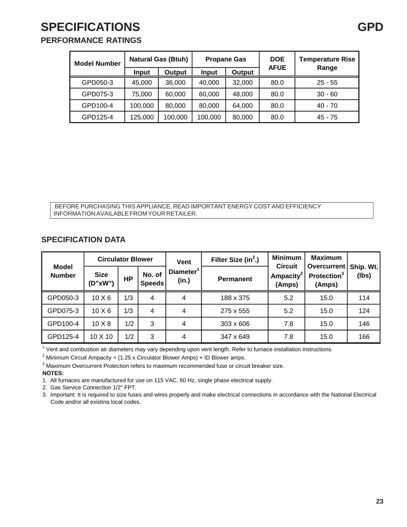
GPD050-3 10 X 6 1/3 4 4 188 x 375 5.2 15.0 114
GPD075-3 10 X 6 1/3 4 4 275 x 555 5.2 15.0 124
GPD100-4 10 X 8 1/2 3 4 303 x 606 7.8 15.0 146
GPD125-4 10 X 10 1/2 3 4 347 x 649 7.8 15.0 166
Ship. Wt.(lbs)
MaximumOvercurrentProtection3
(Amps)
MinimumCircuit
Ampacity2
(Amps)
VentDiameter1
(in.)
ModelNumber
1 Vent and combustion air diameters may vary depending upon vent length. Refer to furnace installation instructions.2 Minimum Circuit Ampacity = (1.25 x Circulator Blower Amps) + ID Blower amps.3 Maximum Overcurrent Protection refers to maximum recommended fuse or circuit breaker size.NOTES:1. All furnaces are manufactured for use on 115 VAC, 60 Hz, single phase electrical supply.2. Gas Service Connection 1/2" FPT.3. Important: It is required to size fuses and wires properly and make electrical connections in accordance with the National Electrical Code and/or all existing local codes.
Input Output Input OutputGPD050-3 45,000 36,000 40,000 32,000 80.0 25 - 55
GPD075-3 75,000 60,000 60,000 48,000 80.0 30 - 60
GPD100-4 100,000 80,000 80,000 64,000 80.0 40 - 70
GPD125-4 125,000 100,000 100,000 80,000 80.0 45 - 75
Temperature RiseRange
Natural Gas (Btuh)Model Number Propane Gas DOEAFUE
BEFORE PURCHASING THIS APPLIANCE, READ IMPORTANT ENERGY COST AND EFFICIENCY INFORMATION AVAILABLE FROM YOUR RETAILER.
PERFORMANCE RATINGS
SPECIFICATION DATA
GPD

24
DIMENSIONS
1-3/8"
3-1/4"
GAS INLET
LOW VOLTAGE
ELEC.
GAS INLET
LOW VOLTAGE
ELEC.
39"
2"
12-3/4"8"
13-1/4"
A
B
14-1/4"
28"
19-5/8" 3-1/4"
3/4"
3/4" 3-1/8"
5-1/16"
10-1
/4"
Model Number A B
GMT045-3*GMT070-3* 14" 12 1/2"
GMT070-4*GMT090-3*GMT090-4*
17-1/2" 16"
GMT090-5*GMT115-5* 21" 19-1/2"
GMT140-5* 24-1/2" 23"
SW B1 0 3 6 1 1
MINIMUM CLEARANCES TO COMBUSTIBLE MATERIALS (INCHES)
*36" clearance for serviceability recommended.
Vent**Sides Rear Front*
Approved for line contact in the horizontal position.
Top
**Single Wall Vent (SW) to be used only as a connector. Refer to the venting tables outlined in the Installation Manual for additional venting requirements.
GMT

DIMENSIONS
25
4-3/8"
GAS INLET
LOW VOLTAGE
ELEC.
39"
A
B
28"
19-5/8" 3/4"
3/4"
1-3/8"
8-5/8"
GAS INLET
11-3/8"
1-7/8"
10-1/4"
14-1/4"
Model Number A B Non CombustibleFloor Base
GDT045-3*GDT070-3* 14" 12-1/2" SBT14
GDT090-4* 17-1/2" 16" SBT17
GDT115-5* 21" 19-1/2" SBT21
SW B1 0 3 6 1 1
**Single Wall Vent (SW) to be used only as a connector. Refer to the venting tables outlined in the Installation Manual for additional venting requirements.
MINIMUM CLEARANCES TO COMBUSTIBLE MATERIALS (INCHES)
*36" clearance for serviceability recommended.
Vent**Sides Rear Front* Top
GDT

26
DIMENSIONS
` 71.123.49
25.88
10.16
31.2799.06
11.59
20.16
51.4343.501.91
1.91
1.911.911.91
A
B
7.94
13.18
10.16
25.88
58.42
10.0012.38 (TYP)
38
SW B Horizontal Upflow1 0 3 6 1 8 1
Top
**Single Wall Vent (SW) to be used only as a connector. Refer to the venting tables outlined in the Installation Manual for additional venting requirements.
MINIMUM CLEARANCES TO COMBUSTIBLE MATERIALS (INCHES)
*36" clearance for serviceability recommended.
Vent**Sides Rear Front*
GMP
Model Number A B Non CombustibleFloor Base
GMP050-32GMP075-32 14" 12-1/2" SBM14
GMP100-42 17-1/2" 16" SBM17
GMP125-52 21.0" 19.5" SBGM21
GMP150-52 25 23 SBM24

DIMENSIONS
27
GMPE
10 3/16"
1 3/8" (TYP)28"
4"
12 5/16" 39"
4 9/16"
7 15/16"
20 1/4"
17 1/8" 3/4"
3/4"
A
B 3/4" 45º
3/4"
3/4"
C
10 3/16"
4"
5 3/16"
3 1/8"
3 15/16"(TYP)
4 7/8"(TYP)
15"
23"
Model Number A B C Non CombustibleFloor Base
GMPE075-3 17.5" 16.0" 16.0" SBM17
GMPE100-4GMPE125-5 21.0" 19.5" 19.5" SBM21
SW B1 0 3 6 1 1
**Single Wall Vent (SW) to be used only as a connector. Refer to the venting tables outlined in the Installation Manual for additional venting requirements.
MINIMUM CLEARANCES TO COMBUSTIBLE MATERIALS (INCHES)
*36" clearance for serviceability recommended.
Vent**Sides Rear Front* Top

28
MAINTENANCE
MAIN BURNER ADJUSTMENT1. The main burners should not need adjustment in most
instances. However, burner air shutters on some mod-els are provided should adjustment be necessary. Afterthe furnace has been in operation for at least five (5)minutes loosen the air shutter locking screws and closethe shutter until yellow tipped flames appear. Slowly openthe shutter until the yellow disappears. Retighten thelocking screw.
MOTOR LUBRICATION AND MAINTENANCE1. The circulating air blower is equipped with bearings that
are permanently lubricated by the motor manufacturerand require no lubrication. At the time of the monthlyfilter inspection clean the exterior of the circulating mo-tor, especially around the perimeter air holes to preventthe possibility of overheating due to an accumulation ofdust or dirt on the windings and motor casing. Dirty fil-ters will restrict the air flow over the motor windings andpossibly cause an overheating condition.
2. The induced draft vent motors are prelubricated by themotor manufacturer and require no attention.
INSPECTING / CLEANING HEAT EXCHANGERSNOTE: It is the obligation of the installer to advise the userto have the furnace inspected and cleaned annually. To cleanthe heat exchanger perform the following:1. Adjust the room thermostat to its lowest setting.2. Turn off the gas and electric supply to the furnace.
3 Remove the access control door.4. Disconnect the gas supply line attached to the gas valve.5. Remove the wire connected to the gas valve.6. Remove the burner box assembly. Care must be exer-
cised to avoid damage to any components.7. Inshot burners should not require cleaning. However, if
they exhibit signs of corrosion they can be cleaned bybrushing with a stiff wire brush.
8. Remove the vent from the furnace venter blower.9. Remove the venter blower and collector box.10. With a stiff wire brush on a flexible handle and remove
any loose scale from the heat exchanger at both theflue and burner openings.
11. With a vacuum remove any loose scale dislodged andany additional debris found in the heat exchanger.
12. Visually inspect the heat exchanger cells for any fail-ures using a bright light. If any failures are discov-ered it is important to disable the furnace and no-tify the end user that it remains inoperable untilrepairs are implemented.
13. Reassemble the furnace in the reverse order. Note: Noadditional screws or wires are supplied. All componentsmust be reassembled to avoid an unsafe condition.
14. Reconnect gas supply and check for leaks using a soapsolution. If a flexible gas line is used examine it for cracksor weakness. Replace if necessary.
15. Restore electrical power.
16. Follow the lighting instructions to place the furnace intooperation.
AIR FILTERS
1. Prior to inspecting air filters, turn off the electric supplyto the appliance. Instructions for replacing filters can befound in the Installation and Operating Instructions. Donot operate the furnace without air filters in place.
2. Inspect filters monthly. Failure to change air filters regu-larly can result in permanent damage to the circulatingblower motor and adversely effect the furnace perfor-mance.

MAINTENANCE
29
IGNITION SYSTEM
1. Integrated control boards are not field servicable.2. Check for tight wire connections on the integrated con-
trol board.3. Turn off electrical power to furnace before tightening any
electrical connections.
VENT AND COMBUSTION AIR INSPECTION1. Check that the vent and vent connector are securely
attached to the furnace and show no signs of deteriora-tion or sagging.
2. Check for leaks around the fittings or joints.3. Check for proper vent pipe clearance from combustible
materials. Check vent pipe for proper venting to the out-side of the structure. Follow all local code requirementsfor proper vent piping, termination and required clear-ances.
DRAIN SYSTEM (Condensing Furnaces Only)1. Inspect the drain system during the normal monthly fil-
ter change. Any blockages should be corrected to in-sure proper operation of the furnace.
GENERAL FURNACE INSPECTIONThe preceding sections cover specific areas of maintenance;however, on a regular basis the following should be inspected:1. Return air connection(s) must be sealed to the furnace
and terminate outside the furnace room.2. The return air plenum(s) must be free of holes or other
openings and show no signs of distortion.3. The seal between the furnace and the base or flooring to
which the furnace is mounted should show no signs ofdeterioration, sags, cracks or gaps and must provide adefinite seal between the base or flooring and the fur-nace.

30
SERVICING
CUBIC FEET
1 02
34
5 6
8
7
9 1 0
23
45 6
8
7
912
34
56
8
7
9 123
45
6
8
7
9
1 Million 100 Thousand 10 Thousand 1 Thousand
One
Foot
Quarter
Foot
GAS RATE -- CUBIC FEET PER HOURSize of Test Dial Size of Test Dial
Secondsfor One
Revolution
1/4cu/ft
1/2cu/ft
1cu/ft
2cu/ft
5cu/ft
Secondsfor One
Revolution
1/4cu/ft
1/2cu/ft
1cu/ft
2cu/ft
5cu/ft
10 90 180 360 720 1800 36 25 50 100 200 50011 82 164 327 655 1636 37 -- -- 97 195 48612 75 150 300 600 1500 38 23 47 95 189 47413 69 138 277 555 1385 39 -- -- 92 185 46214 64 129 257 514 1286 40 22 45 90 180 45015 60 120 240 480 1200 41 -- -- -- 176 43916 56 113 225 450 1125 42 21 43 86 172 42917 53 106 212 424 1059 43 -- -- -- 167 41918 50 100 200 400 1000 44 -- 41 82 164 40919 47 95 189 379 947 45 20 40 80 160 40020 45 90 180 360 900 46 -- -- 78 157 39121 43 86 171 343 857 47 19 38 76 153 38322 41 82 164 327 818 48 -- -- 75 150 37523 39 78 157 313 783 49 -- -- -- 147 36724 37 75 150 300 750 50 18 36 72 144 36025 36 72 144 288 720 51 -- -- -- 141 35526 34 69 138 277 692 52 -- -- 69 138 34627 33 67 133 265 667 53 17 34 -- 136 34028 32 64 129 257 643 54 -- -- 67 133 33329 31 62 124 248 621 55 -- -- -- 131 32730 30 60 120 240 600 56 16 32 64 129 32131 -- -- 116 232 581 57 -- -- -- 126 31632 28 56 113 225 563 58 -- 31 62 124 31033 -- -- 109 218 545 59 -- -- -- 122 30534 26 53 106 212 529 60 15 30 60 120 30035 -- -- 103 206 514

SERVICING
31
Complaint No Heat Unsatisfactory Heat
POSSIBLE CAUSE
DOTS IN ANALYSISGUIDE INDICATE
"POSSIBLE CAUSE"SY
MPT
OM
Sys
tem
Will
Not
Sta
rt
Bur
ner W
on't
Igni
te
Bur
ner I
gnite
s-Lo
cks
Out
Bur
ner S
huts
Off
prio
r to
T'S
tat b
eing
Sat
isfie
d
Sho
rt C
ycle
s
Long
Cyc
les
Soo
t and
/or F
umes
Too
Muc
h H
eat
Not
Eno
ugh
Hea
t
Test MethodRemedy
See
Serv
ice
Proc
edur
e R
efer
ence
Power Failure • Test Voltage S-1
Blown Fuse • Test Voltage S-4
Loose Connection • Check Wiring S-2
Shorted or Broken Wires • Check Wiring S-3
No Low Voltage • Check Transformer S-4
Faulty Thermostat • • • • Check Thermostat S-3
Faulty Transformer • Check Transformer S-4
Poor or High Resistance Ground • Measure Ground Resistance S-13
Improper Heat Anticipator Setting • • • • Adjust Heat Anticipator Setting S-3
Improper Thermostat Location • • • • Relocate Thermostat
Faulty Limit or Roll Out Switch • • Test Control S-5 & 7
Faulty Flame Sensor • Test Flame Sensor S-14
Faulty Ignition Control • • Test Control S-13
Gas Valve or Gas Supply Shut Off • Turn Valves to On Position S-11
Faulty Induced Draft Blower • • Test Blower S-9
Broken or Shorted Ignitor • Test Ignitor S-12
Dirty Flame Sensor, Low uA • Clean Flame Sensor S-14
Flame Sensor not in Flame, Low uA • Test/Adjust Position of Flame Sensor S-14
Faulty Gas Valve • • • Replace Gas Valve S-11
Open Auxiliary Limit • • Reset Control S-6
Improper Air Flow or Distribution • • Check Duct Static S-21
Cycling on Limit • • • Check Controls & Temperature Rise S-5 & 22
Delayed Ignition • Test for Delayed Ignition S-19
Flashback • Test for Flashback S-20
Orifice Size • • • Check Orifices S-16
Gas Pressure • • • • Check Gas Pressure S-18
Cracked Heat Exchanger • Check Burner Flames S-15
Stuck Gas Valve • • • Replace Gas Valve S-11
Furnace Undersized • Replace with Proper Size Furnace
Faulty Pressure Switch • • • Test Pressure Switch S-8
Blocked or Restricted Flue • Check Flue/Drawdown Pressure S-8
Open Roll Out Switch • • Test Control S-7
Bouncing On Pressure Switch • Test Negative Pressure S-8
GAS HEATING - SERVICE ANALYSIS GUIDE

32
SERVICINGSERVICING SECTION INDEX
S-1 Checking Voltage ......................................................................................................... 33
S-2 Checking Wiring ........................................................................................................... 33
S-3A Thermostat and Wiring ................................................................................................ 33
S-3B Heating Anticipator ....................................................................................................... 34
S-3C Cooling Anticipator ....................................................................................................... 34
S-4 Checking Transformer and Control Circuit .................................................................. 34
S-5 Checking Primary Limit Control ................................................................................... 37
S-6 Checking Auxiliary Limit Control ................................................................................... 38
S-7 Checking Flame Rollout Control .................................................................................. 39
S-8 Checking Pressure Control .......................................................................................... 41
S-9 Checking Air Circulator Blower Motor or Induced Draft Blower Motor .......................... 44
S-9A Checking Variable Speed Air Circulator Blower Motor.................................................. 44
S-10 Checking Capacitor ...................................................................................................... 48
S-10A Resistance Check ........................................................................................................ 49
S-11 Checking Gas Valve ..................................................................................................... 49
S-12 Checking Hot Surface Ignitor ........................................................................................ 50
S-13 Checking Integrated Ignition Controls ........................................................................... 50
S-14 Checking Flame Sensor............................................................................................... 56
S-15 Checking Main Burners ................................................................................................ 57

SERVICING
33
S-1 CHECKING VOLTAGE
1. Remove the burner door on 80% furnace or blower com-partment door on 90% furnace to gain entry to JunctionBox.
2. Remove cover from Junction Box and gain access toincoming power lines.
With Power ON:
3. Using a voltmeter, measure the voltage across the hotand neutral connections.
NOTE: To energize the furnace, the Door Interlock Switchmust be engaged at this point.4. No reading - indicates open wiring, open fuse, no power,
or etc. from unit to fused disconnect service. Repair asneeded.
5. With ample voltage at line voltage connectors, energizethe furnace blower motor by jumpering terminals R to Gon the integrated ignition control.
6. With the blower motor in operation, the voltage shouldbe 115 volts ± 10 percent.
7. If the reading falls below the minimum voltage, checkthe line wire size. Long runs of undersized wire can causelow voltage. If wire size is adequate, notify the local powercompany of the condition.
8. After completing check and/or repair, replace JunctionBox cover and reinstall burner compartment door on 80%or blower compartment door on 90% furnace.
9. Turn on electrical power and verify proper unit operation.
S-2 CHECKING WIRING
1. Check wiring visually for signs of overheating, damagedinsulations and loose connections.
2. Using an ohmmeter to check continuity of any suspectedopen wires.
3. If any wires must be replaced, replace with AWM, 105°C.4/64 thick insulation of the same gauge or its equivalent.
S-3 CHECKING THERMOSTAT, WIRING ANDANTICIPATOR
S-3A Thermostat and Wiring
1. Remove the blower compartment door to gain access tothe thermostat low voltage wires located at the furnaceintegrated control module terminals.
2. Remove the thermostat low voltage wires at the furnacecontrol panel terminal board.
3. Jumper terminals R to W (W1 and W2) on the integratedignition control.
With Power On (and Door Interlock Switch closed):
4. Induced Draft Motor must run and pull in pressure switch.5. If the hot surface ignitor heats and at the end of the this
ignitor warm-up period the gas valve opens and the burn-ers ignite, the trouble is in the thermostat or wiring.
6. With power off, check the continuity of the thermostatand wiring. Repair or replace as necessary.
If checking the furnace in the air conditioning mode, pro-ceed as follows.7. With power off, Jumper terminals R to Y to G.8. Turn on the power.9. If the furnace blower motor starts and the condensing
unit runs, then the trouble is in the thermostat or wiring.Repair or replace as necessary.
10. After completing check and/or repair of wiring and checkand/or replacement of thermostat, reinstall blower com-partment door.
11. Turn on electrical power and verify proper unit operation.
S-3B Heating AnticipatorThe heating anticipator is a wire wound adjustable heaterwhich is energized during the "ON" cycle to help preventoverheating of the conditioned space.The anticipator is a part of the thermostat and if it should failfor any reason, the thermostat must be replaced.

34
SERVICINGThe heating anticipator setting for furnaces covered in thismanual is 0.70 Amps.If the anticipator current draw is unknown, then an amp drawshould be taken to determine the anticipator setting. Usean amprobe as shown in the following drawing.
10 TURNS OFTHERMOSTAT WIRE(From "W" on thermostat)
STATIONARY JAWOF AMPROBE
READS 4 AMPSCURRENT DRAWWOULD BE .4 AMPS
Checking Heating Anticipator Current (Amp) Draw
S-3C Cooling AnticipatorThe cooling anticipator is a small heater (resistor) in thethermostat. During the "OFF" cycle it heats the bimetal el-ement helping the thermostat call for the next cooling cycle.This prevents the room temperature from rising too high be-fore the system is restarted. A properly sized anticipatorshould maintain room temperature within 1 1/2 to 2 degreesrange.The anticipator is fixed in the subbase and is not to be re-placed. If the anticipator should fail for any reason, the sub-base must be changed.
S-4 CHECKING TRANSFORMER AND CON-TROL CIRCUIT
A step-down transformer 120 volt primary to 24 volt second-ary, 40 VA (Heating and Cooling Models) supplies amplecapacity of power for either operation.
1. Remove blower compartment door to gain access to thethermostat low voltage wires located at the furnace inte-grated control module.
2. Remove the thermostat low voltage wires at the furnaceintegrated control module terminals.
With Power On (and Door Interlock Switch closed):5. Check transformer primary voltage at incoming line volt-
age connections, fuse, splices, and blower door inter-lock switch.
6. If line voltage is available to the primary side of trans-former and not at secondary side, the transformer isinoperative. Replace.
7. After completing check and/or replacement of trans-former and check and/or repair of control circuit, rein-stall blower compartment door.
8. Turn on electrical power and verify proper unit opera-tion.
S-5 CHECKING PRIMARY LIMIT CONTROLThe 80% furnaces use nonadjustable, automatic reset, pri-mary limits part # B13701(87-99) and B13709*. The illustra-tion below shows how to test limit controls. See the follow-ing note BEFORE replacing the limit control.NOTE: The following service problems could cause the pri-mary limit to open up and should be checked first:1. Low air flow. Check for dirty evaporator coil, dirty
blower wheel, blower motor not running or turning tooslow, high duct static pressure (duct system under-sized), high static air filters, return air duct or return grillesundersized.
1. Remove burner compartment door to gain access to theprimary limit.
2. Remove low voltage wires at limit control terminals.3. With an ohmmeter, test between these two terminals
as shown in the following drawing. Should read continu-ous unless heat exchanger temperature is above limitcontrol setting. If not as above, replace the control.
VOLT / OHM METER

SERVICING
35
4. After completing check and/or replacement of primarylimit control, reinstall burner compartment door.
5. Turn on electrical power and verify proper unit operation.As shown in the following drawing, limit control should readcontinuous unless the heat exchanger temperature is abovelimit control setting. If not as above, replace the control
Volt / Ohm Meter
COLORIDENTIFYING SLEEVES
Testing Primary Limit Control(GMP, GMPN Furnaces)
VOLT / OHM METER
COLORIDENTIFYING TAB
Testing Primary Limit Control(GMNT, GMT Furnaces)
6. After completing check and/or replacement of primarylimit control, reinstall burner compartment door.
7. Turn on electrical power and verify proper unit operation.To aid in identifying these controls, refer to the followingPrimary Limit Charts for temperature setting and length speci-fications.

36
SERVICING
Part Number B1370902 B1370903 B1370905 B1370908 B1370910 B1370911 B1370912 B1370914 B1370915
Open Setting °F 210 240 290 160 170 220 240 220 230
Length (Inches) 3" 3" 3" 7" 7" 3" 7" 7" 3"GMP 050-3* --- --- --- --- --- --- 1 --- ---GMP 075-3* --- --- --- 1 --- --- --- --- ---GMP 075-4* --- --- --- --- --- 1GMP 100-3* --- --- 1 --- --- --- --- --- ---GMP 100-4* --- --- 1 --- --- --- --- --- ---GMP 100-5* 1 --- --- --- --- --- --- ---GMP 125-4* 1 --- --- --- --- --- --- --- ---GMP 125-5* --- --- --- --- --- --- 1 --- ---GMP 150-5* --- --- --- --- --- --- --- 1 ---
GMPE 075-3* --- --- --- --- 1 --- --- --- ---GMPE 100-4* --- --- --- --- --- --- 1 --- ---GMPE 125-5 --- --- --- 1 --- --- --- --- ---
GMPH 050-3* --- 1 --- --- --- --- --- --- ---GMPH 075-3* --- 1 --- --- --- --- --- --- ---GMPH 080-5* --- --- --- --- 1 --- --- --- ---GMPH 120-5* --- --- --- --- --- --- --- 1 ---
GPD 050-3* --- --- --- --- --- --- 1 --- ---GPD 075-3* 1 --- --- --- --- --- --- --- ---GPD 100-4* --- --- --- --- --- --- --- --- 1GPD 125-4* --- --- --- --- --- 1 --- --- ---
80% Primary Limit ( GMP - GMPE - GMPH - GPD )
Part Number B1370187 B1370190 B1370191 B1370192 B1370193 B1370194 b1370195 B1370196 B1370919 B1370920 B1370921
Open Setting °F 160 210 220 230 240 250 300 320 170 F 180 F 240 F
Length (Inches) 3" 3" 3" 3" 3" 3" 3" 3" 7" 7" 7"GDT 045-3* --- --- --- --- --- --- 1 --- --- --- ---GDT 070-3* --- --- --- --- 1 --- --- --- --- --- ---GDT 090-4* --- --- --- --- --- 1 --- --- --- --- ---GDT 115-5* --- --- 1 --- --- --- --- --- --- --- ---
GMT 045-3* --- --- --- --- --- --- 1 --- --- --- ---GMT 070-3* --- --- --- --- --- --- --- --- 1 ---GMT 070-4* --- --- --- --- --- --- --- --- 1 --- ---GMT 090-3* --- 1 --- --- --- --- --- --- --- --- ---GMT 090-4* --- 1 --- --- --- --- --- --- --- --- ---GMT 090-5* --- --- --- --- --- --- --- 1 --- --- ---GMT 115-5* --- --- 1 --- --- --- --- --- --- --- ---GMT 135-5* 1 --- --- --- --- --- --- --- --- --- ---GMT 140-5* 1 --- --- --- --- --- --- --- --- --- ---
GMTH 045-3* --- --- --- 1 --- --- --- --- --- --- ---GMTH 070-4* --- --- --- --- --- --- --- --- --- --- 1GMTH 090-5* --- --- --- --- 1 --- --- --- --- --- ---GMTH 115-5* --- --- --- --- --- --- 1 --- --- --- ---
80% Primary Limit ( GDT - GMT - GMTH )

SERVICING
37
Part Number B1370187 B1370188 B1370189 B1370190 B1370906 B1370908 B1370909 B1370910Open Setting °F 160 170 200 210 150 160 160 170Length (Inches) 3" 3" 3" 3" 7" 7" 3" 7"GMPN 040-3* --- --- --- --- 1 --- --- ---GMPN 060-3* --- --- --- --- --- 1 --- ---GMPN 080-4* --- --- --- --- --- 1 --- ---GMPN 100-4* --- --- --- --- --- --- --- 1GMPN 120-5* --- --- --- --- --- 1 --- ---
GSM 060-3 --- --- --- --- --- --- 1 ---GSM 080-4 --- --- --- --- --- 1 --- ---GSM 100-4 --- --- --- --- --- --- --- 1
GSMS 060-3 --- --- --- --- --- --- 1 ---GSMS 080-3 --- --- --- --- --- 1 --- ---GSMS 100-4 --- --- --- --- --- --- --- 1
GMNT 040-3* --- 1 --- --- --- --- --- ---GMNT 060-3* 1 --- --- --- --- --- --- ---GMNT 080-4* --- --- 1 --- --- --- --- ---GMNT 100-4* --- 1 --- --- --- --- --- ---GMNT 120-5* --- 1 --- --- --- --- --- ---
GMNTE 060-3* --- 1 --- --- --- --- --- ---GMNTE 080-4* --- 1 --- --- --- --- --- ---GMNTE 100-4* --- --- --- 1 --- --- --- ---GMNTE 120-5* --- --- --- 1 --- --- --- ---
90% Primary Limit

38
SERVICINGS-6 CHECKING AUXILIARY LIMIT CONTROLThe auxiliary limit switch (B13701-55) is a safety controlthat senses high temperature within the furnace or duct work.This control is preset to open at 120°F and close at 90°F. Itis not adjustable and automatically resets. The control islocated in the blower compartment of the furnace on theblower housing. Auxiliary limits may be on the side or frontof the blower housing.
Part Number B13701-55Open Setting °F 120GDT 045-3* 1GDT 070-3* 1GDT 090-4* 1GDT 115-5* 1
GMP 050-3* 1GMP 075-3* 1GMP 075-4* 1GMP 100-3* 1GMP 100-4* 1GMP 100-5* 1GMP 125-4* 1GMP 125-5* 1GMP 150-5* 1
GMPE 075-3* 1GMPE 100-4* 1GMPE 125-5* 1
GMPH 050-3* 1GMPH 075-3* 1GMPH 080-5* 1GMPH 120-5* 1
GMT 045-3* 1GMT 070-3* 1GMT 070-4* 1GMT 090-3* 1GMT 090-4* 1GMT 090 -5* 1GMT 115-5* 1GMT 135-5* 1GMT 140-5* 1
GMTH 045-3* 1GMTH 070-4* 1GMTH 090-5* 1GMTH115-5* 1
GPD 050-3* 1GPD 075-3* 1GPD 100-4* 1GPD 125-4* 1
80% Auxiliary Limit
Part Number B13701-55Open Setting °F 120GMPN 040-3* NAGMPN 060-3* NAGMPN 080-4* NAGMPN 100-4* NAGMPN 120-5* NA
GSM 060-3 NAGSM 080-4 NAGSM 100-4 NA
GSMS 060-3 NAGSMS 080-3 NAGSMS 100-4 NA
GMNT 040-3* 1GMNT 060-3* 1GMNT 080-4* 1GMNT 100-4* 1GMNT 120-5* 1
GMNTE 060-3* 1GMNTE 080-4* 1GMNTE 100-4* 1GMNTE 120-5* 1
90% Auxiliary Limit
AUXILIARY LIMIT CONTROL
AUXILIARY LIMIT CONTROL
BLOWER HOUSING
Auxiliary Limit Control Location(Side location shown)
GMP furnace with the edge card control board is connectedin series with the primary limit which connects to the inte-grated ignition control. Interruption of the circuit will cause a(4) flash code on the control board. These symptoms areidentical to a trip of the primary limit control. The air circula-tion blower will run continuously.

SERVICING
39
GDP, GDT, GMP, GMPE, GMNT, GMT, GMTH and GPDfurnaces using the 9-pin connector on the control board isconnected in series through the rollout switches. Interrup-tion of the circuit will cause a (1) flash code of ignitionfailure. If its temperature should be exceeded, it will open,interrupting the voltage to the gas valve causing it to close.The auxiliary limit control is designed to prevent furnaceoperation in case of main blower failure. It may also openif the power supply is interrupted while the furnace is fir-ing.
1. Remove blower compartment door to gain access tothe auxiliary limit control which is located on the blowerhousing or on the blower deck.
2. Remove the wires from the auxiliary limit control ter-minals.
3. Use an ohmmeter, test for continuity across the twoterminals (refer to the following auxiliary limit controlfigure). No reading indicates the control is open.
4. Verify proper operation of blower motor and staticpressure of duct system. Problem could be causedby a dirty evaporator coil.
VOLT / OHM METER
Testing Auxiliary Limit Control
S-7 CHECKING FLAME ROLLOUT CONTROLA temperature activated manual reset control is mountedto the manifold assembly as shown in the following illus-tration. Locations of the rollout switch may vary.
ROLLOUT SWITCH
Flame Rollout Switch Location(80% Upflow Furnace Shown, Downflow Similar)
The control is designed to open should a flame roll out occur.An over firing condition or flame impingement on the heatshield may also cause the control to open.On some models the ignition control diagnostic light will flash(1) one time indicating a trip of the rollout switch. These symp-toms are identical to a trip of the auxiliary limit control.On other models the ignition controls diagnostic light will flash(4) four times indicating an open primary limit, rollout switch,auxiliary switch or stack overtemp switch open. Check theflash codes for the model you are working on.The circuit between the ignition control and gas valve will beinterrupted when the rollout switch opens up.Refer to the Rollout Limit Charts on the next page for tem-perature settings and part numbers.
1. Remove the burner compartment door to gain access tothe rollout switch(es) mounted to burner bracket.
The servicer should reset the ignition control by opening andclosing the thermostat circuit. Then look for the ignitor glow-ing which indicates there is power to the ignition control.Measure the voltage between each side of the rollout controland ground while the ignition control tries to power the gasvalve.2. Measure the voltage between each side of the rollout con-
trol and ground during the ignition attempt. Refer to thefollowing figure.
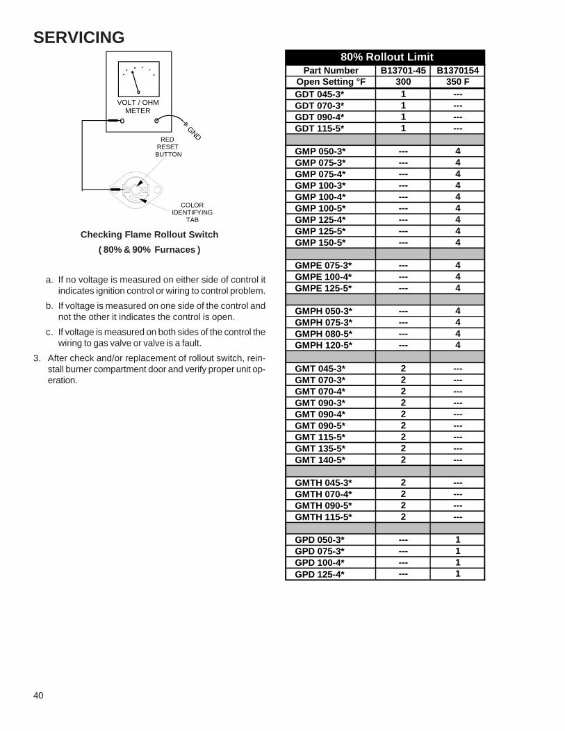
40
SERVICING
VOLT / OHM METER
GND RED RESETBUTTON
COLORIDENTIFYING TAB
Checking Flame Rollout Switch( 80% & 90% Furnaces )
a. If no voltage is measured on either side of control itindicates ignition control or wiring to control problem.
b. If voltage is measured on one side of the control andnot the other it indicates the control is open.
c. If voltage is measured on both sides of the control thewiring to gas valve or valve is a fault.
3. After check and/or replacement of rollout switch, rein-stall burner compartment door and verify proper unit op-eration.
Part Number B13701-45 B1370154Open Setting °F 300 350 FGDT 045-3* 1 ---GDT 070-3* 1 ---GDT 090-4* 1 ---GDT 115-5* 1 ---
GMP 050-3* --- 4GMP 075-3* --- 4GMP 075-4* --- 4GMP 100-3* --- 4GMP 100-4* --- 4GMP 100-5* --- 4GMP 125-4* --- 4GMP 125-5* --- 4GMP 150-5* --- 4
GMPE 075-3* --- 4GMPE 100-4* --- 4GMPE 125-5* --- 4
GMPH 050-3* --- 4GMPH 075-3* --- 4GMPH 080-5* --- 4GMPH 120-5* --- 4
GMT 045-3* 2 ---GMT 070-3* 2 ---GMT 070-4* 2 ---GMT 090-3* 2 ---GMT 090-4* 2 ---GMT 090-5* 2 ---GMT 115-5* 2 ---GMT 135-5* 2 ---GMT 140-5* 2 ---
GMTH 045-3* 2 ---GMTH 070-4* 2 ---GMTH 090-5* 2 ---GMTH 115-5* 2 ---
GPD 050-3* --- 1GPD 075-3* --- 1GPD 100-4* --- 1GPD 125-4* --- 1
80% Rollout Limit

SERVICING
41
Part Number B13701-45 B1370154Open Setting °F 300 350 FGMPN 040-3* 4 ---GMPN 060-3* 4 ---GMPN 080-4* 4 ---GMPN 100-4* 4 ---GMPN 120-5* 4 ---
GSM 060-3 --- 2GSM 080-3 --- 2GSM 100-4 --- 2
GSMS 060-3 --- 2GSMS 080-4 --- 2GSMS 100-4 --- 2
GMNT 040-3* 4 ---GMNT 060-3* 4 ---GMNT 080-4* 4 ---GMNT 100-4* 4 ---GMNT 120-5* 4 ---
GMNTE 060-3* 4 ---GMNTE 080-4* 4 ---GMNTE 100-4* --- 4GMNTE 120-5* 4 ---
90% Rollout Limit
S-8 CHECKING PRESSURE CONTROLThe pressure control is a safety device to prevent the com-bustion cycle from occurring with inadequate venting causedby a restricted or blocked vent pipe on the 80% and 90%furnaces.
1. Remove burner compartment door to gain access to pres-sure switch(es).
2. Remove wires from the pressure switch(es) electricalterminals.
3. Using a VOM check from common terminal to NC (Nor-mally Closed) - should read closed. Check from Com-mon to NO (Normally Open) - should read open.
If switch reads as above proceed to Step 4, otherwise re-place control.4. Remove the pressure control hose from the control and
interconnect with an inclined manometer as shown inthe following figures.
INDUCED DRAFT BLOWER PRESSURE SWITCH
PRESSURE SWITCHHOSE
1/4" TEE
HOSE TO INDUCED DRAFT BLOWER TAP
INCLINED MANOMETER
OPEN TO ATMOSPHERE
INDUCEDDRAFT
BLOWER
ID Blower Pressure SwitchNegative Pressure Measurement
(80% Furnace shown for illustration purposes)
OPEN TOATMOSPHERE
INCLINED MANOMETER
HOSE TO INDUCED DRAFT BLOWER TAP
1/4" TEE
INDUCED DRAFT BLOWERPRESSURE SWITCH
PRESSURE SWITCHHOSE
INDUCEDDRAFT
BLOWER
*
*
*
* *
*
*
M 1
2
3P
C
ON
OFF
COIL COVERPRESSURE SWITCH
ID Blower Pressure SwitchNegative Pressure Measurement
(90% Furnace shown for illustration purposes)
Reconnect pressure switch electrical wires.
4. Energize furnace for heating cycle. The induced draftblower motor will begin to run. The inclined manometershould read a negative pressure.
5. Remove and check the two electrical wires and usingthe VOM check from Common to NC (Normally Closed)- should read open. Check from Common to NO (Nor-mally Open) - should read closed. If not as above, re-place control.
6. Reconnect wires to the control and place in a heatingcycle.
NOTE: See the following pages for the pressure switch trippoints and usage charts.

42
SERVICING
Low FireNegative Pressure Part # High Fire
Negative Pressure Part #
GSM 060-3 -0.38 B13701-57 -1.40 B13701-56
GSM 080-4GSM 100-4
-0.38 B13701-57 -1.10 B13701-59
PRESSURE SWITCH TRIP POINTS AND USAGE CHART
Trip Point Inches Water Column (" w.c.)
0 to 8,000 ft.MODEL
Low FireNegative Pressure
High FireNegative Pressure Part #
GMNTE 060-3* -0.60 -1.25 B13702-01
GMNTE 080-4* -0.55 -0.95 B13702-04
GMNTE 100-4* -0.35 -0.85 B13702-02
GMNTE 120-5* -0.40 -0.75 B13702-03
Trip Point Inches Water Column (" w.c.)
0 to 8,000 ft.
PRESSURE SWITCH TRIP POINTS AND USAGE CHART
MODEL
Negative Pressure Part #
GMT/GMTH/GDT 045-3*GMT/GMTH/GDT 070-3*
GMT 070-4*GMT 090-3*
GMT/GDT 090-4*
-0.60 B13701-42
GMT/GMTH 090-5*GMT/GDT 115-5*
-0.70 B13701-58
GMTH 115-5* -0.85 B13701-50
GMT 140-5* -0.75 B13701-79
PRESSURE SWITCH TRIP POINTS AND USAGE CHART
MODEL 0 to 8,000 ft.
Trip Point Inches Water Column (" w.c.)

SERVICING
43
Negative Pressure Part #
GSMS 060-3 / 080-4 / 100-4 -0.38 B13701-57
GMPN/GMNT 040-3*GMPN 060-3*
-1.19 B13701-48
GMNT 060-3*GMPN 080-4*
GMPN/GMNT 100-4*GMPN 120-5*
-0.85 B13701-50
GMNT 080-4* -1.10 B13701-59
GMNT 120-5* -0.75 B13701-79
PRESSURE SWITCH TRIP POINTS AND USAGE CHART
MODEL
Trip Point Inches Water Column (" w.c.)
0 to 8,000 ft.
Negative Pressure Part #
GMP/GMPH/GPD 050-3*GMPH 080-5GMP 100-3*
GMP/GMPE/GPD 100-4*GMP 100-5*
GMPH 120-5*GMP/GPD 125-4*
GMP/GMPE 125-5*
-0.40 B13701-26
GMP/GMPE/GPD 070-3GMP/GMPH 075-4*
-0.35 B13701-33
GMP 150-5 -0.60 B13701-42
PRESSURE SWITCH TRIP POINTS AND USAGE CHART
MODEL
Trip Point Inches Water Column (" w.c.)
0 to 8,000 ft.

44
SERVICINGS-9 CHECKING AIR CIRCULATOR BLOWER
MOTOR OR INDUCED DRAFT BLOWERMOTOR
1. Remove blower compartment door to gain access to thecirculator blower motor and induced draft blower motorwire leads connected at integrated ignition control.
2. Disconnect the motor wire leads from its connection pointat integrated ignition control module and capacitor if ap-plicable.
3. Using and ohmmeter, test for continuity between eachof the motor leads.
4. Touch one probe of the ohmmeter to the motor frame(ground) and the other probe in turn to each lead.
If the windings do not test continuous or a reading is ob-tained to ground, replace the motor.5. After completing check and/or replacement of circulator
blower motor or induced draft blower motor, reinstallblower compartment door.
6. Turn on electrical power and verify proper unit operation.
S-9A CHECKING VARIABLE SPEED AIR CIRCU-LATOR BLOWER MOTOR
Variable Speed furnaces incorporate the GE© ICM or vari-able speed blower motors for greater efficiency. ECM/ICMmotors vary the motor RPMs to provide a set volume of airover a wide range of conditions. These motors use an elec-tronic control module attached to the motors end bell tocontrol motor operation. Some unique features of thesemotors are:1. Constant Airflow. These motors will maintain constant
airflow in excess of .80 static. In other words, as thestatic increases so does the motors RPM so that a con-stant CFM is maintained.
NOTE: The motor in these units will move more air underhigher static conditions than a similar sized unit using aPSC motor. Because this motor does not load up and re-duce airflow like a PSC motor, in some undersized ductinstallations this may cause noise or high airflow complaints.2. Ramp-up/Ramp-down feature. These motors ramp up
and down at the beginning or end of a cycle to reduceair rush noise.
3. High voltage is present at these motors all the time.Motor operation is controlled through the low voltagemotor interface board.
ECM/ICM Control ConnectionsControl functions (G, Y, W, W1, W2) may be active at lessthan 1/2 control voltage. (i.e. 12 volts). Relay contacts oncontrol functions must reliably switch low currents (less than5 MA). Some thermostats (with triac switches) and SolidState Relays may allow enough "leakage" current to turnon "G". Thermostats that "steal" power thru "Y" or otherfunctions are not compatible.The ECM control interface can be as simple as a directconnection to the thermostat. For example: "R" to "G" willcause the fan to come at "Fan-Only" CFM, "R" to "G" to "Y"will cause the fan to come on at Cooling speed and R to Gto W will cause the fan to come on at heating speed. TheECM/ICM control requires a common connection from thetransformer (transformer common to C1, C2 on control). Intypical applications C1 and C2 will be tied together.
Checking ECM/ICM MotorsECM/ICM motors connect directly to the AC Line Voltage.DO NOT insert contactors in series with the ECM/ICM Mo-tor AC Line. The control is powered continuously to insurereliable start-up. The connector plug is polarized, verify andreverify correct connector orientation before applying power.DO NOT force plug into motor and make sure power is offbefore inserting power connector. DO NOT apply voltage toterminals 1 or 2.
Check for line voltage on terminals 4 and 5. Verify terminal3 is ground. terminals. Terminals 1 and 2 are jumpered inthe harness for 120VAC operation.
5
4
3
2
1
Lines 1 and 2 will be connected for 120VAC Power Connector applications only
Gnd
AC Line Neutral Connection
AC Line Hot Connection
}
POWER CONNECTOR(1/2 HP MOTORS)
"Motor Half“(Viewed from Plug End)

SERVICING
45
5
4
3
2
1
Lines 1 and 2 will be connected for 120VAC Power Connector applications only
Gnd
AC Line Neutral Connection
AC Line Hot Connection
}
inductor
POWER CONNECTOR(3/4 & 1 HP MOTORS)
"Motor Half“(Viewed from Plug End)
8
7
6
5
4
3
2
1
16
15
14
13
12
11
10
9
OUT -
ADJUST +/-
Y 1
COOL
DELAY
COMMON 2
W/W1
COMMON 1
OUT +
G (fan)
Y/Y2
EM HT/W2
24VAC (R)
HEAT
BK/Pwm (Speed)
O (Rev Valve)
CONTROL CONNECTOR"Motor Half“
(Viewed from connector end)
Do not apply 24 volts to terminals "Out +" or "Out -".Make sure connector is fully seated.Make sure pins are fully seated in connector housing.Verify C1 and C2 are connected to transformer common.Verify "R" is connected to transformer hot.
After verifying above connections, motor can be tested byapplying 24 volts to control pins. Example: R to G will causethe fan to come at "Fan-Only" CFM, R to G to Y will causethe fan to come on at cooling speed and R to G to W willcause the fan to come on at heating speed.If motor does not respond as noted, ICM control unit is badand should be replaced.

46
SERVICING
NO
TE:
You
mus
t use
the
corre
ct re
plac
emen
t con
trol m
otor
mod
ule
sinc
e th
ey a
re fa
ctor
y pr
ogra
mm
ed fo
r spe
cific
ope
ratin
g m
odes
. Eve
nth
ough
they
look
alik
e, d
iffer
ent m
odul
esm
ay h
ave
com
plet
ely d
iffer
ent f
unct
iona
lity. T
he E
CM
varia
ble
spee
d m
otor
s are
curre
ntly
the
only
mot
ors t
hat c
an h
ave
the
mot
or/c
ontro
l mod
ule
repl
aced
.
IMPO
RTA
NT
NO
TE: U
sing
the
wro
ng m
otor
/con
trol m
odul
e vo
ids
all p
rodu
ct w
arra
ntie
s an
d m
ay p
rodu
ce u
nexp
ecte
d re
sults
.
*MO
ISTU
RE
CH
ECK
:-
Con
nect
ors a
re o
rient
ed "d
own"
(or a
s rec
omm
ende
dby
equ
ipm
ent m
anuf
actu
rer).
-Ar
rang
e ha
rnes
ses
with
"drip
loop
" und
er m
otor
.
-Is
con
dens
ate
drai
n pl
ugge
d?
-C
heck
for l
ow a
irflo
w (t
oo m
uch
late
nt c
apac
ity).
-C
heck
for u
nder
char
ged
cond
ition.
-C
heck
and
plu
g le
aks
in re
turn
duc
ts, c
abin
et.
Sym
ptom
Faul
t Des
crip
tion(
s)Po
ssib
le C
ause
sC
orre
ctiv
e Ac
tion
Cau
tions
and
Not
es
- M
otor
rock
s
slig
htly
whe
n st
artin
g.
- Th
is is
nor
mal
sta
rt-up
for
v
aria
ble
spee
d m
otor
.---
----
----
-
- N
o m
ovem
ent.
- M
anua
l dis
conn
ect s
witc
h of
f or
do
or s
witc
h op
en.
- B
low
n fu
se o
r circ
uit b
reak
er.
- 24
Vac
wire
s m
isw
ired.
- U
nsea
ted
pins
in w
iring
harn
ess
conn
ecto
rs.
- B
ad m
otor
/con
trol m
odul
e. -
Moi
stur
e pr
esen
t in
mot
or o
r con
trol m
odul
e.
- C
heck
230
Vac
pow
er a
t mot
or.
- C
heck
low
vol
tage
(24
Vac
R to
C) a
t mot
or.
- C
heck
low
vol
tage
con
nect
ions
(G
, Y, W
, R, C
) at m
otor
. -
Che
ck fo
r uns
eate
d pi
ns in
con
nect
ors
on
mot
or h
arne
ss.
- Te
st w
ith a
tem
pora
ry ju
mpe
r bet
wee
n R
- G
. -
- Tu
rn p
ower
OFF
prio
r to
repa
ir.
W
ait 5
min
utes
afte
r
dis
conn
ectin
g po
wer
bef
ore
o
peni
ng m
otor
. -
Han
dle
elec
troni
c m
otor
/con
trol w
ith c
are.
- M
otor
rock
s,
but w
on't
star
t.
- Lo
ose
mot
or m
ount
. -
Blo
wer
whe
el n
ot ti
ght o
n m
otor
sha
ft. -
Bad
mot
or/c
ontro
l mod
ule.
- C
heck
for l
oose
mot
or m
ount
. -
Mak
e su
re b
low
er w
heel
is ti
ght o
n sh
aft.
- P
erfo
rm m
otor
/con
trol r
epla
cem
ent c
heck
,
EC
M m
otor
s on
ly.
- Tu
rn p
ower
OFF
prio
r to
repa
ir.
W
ait 5
min
utes
afte
r
dis
conn
ectin
g po
wer
bef
ore
o
peni
ng m
otor
. -
Han
dle
elec
troni
c m
otor
/con
trol w
ith c
are.
- M
otor
osci
llate
s up
&
do
wn
whi
le
bein
g te
sted
off o
f blo
wer
.
- It
is n
orm
al fo
r mot
or to
os
cilla
te w
ith
no lo
ad o
n sh
aft.
----
----
----
- Va
ries
up a
nd d
own
or
inte
rmitt
ent.
- V
aria
tion
in 2
30 V
ac to
mot
or.
- U
nsea
ted
pins
in w
iring
har
ness
conn
ecto
rs.
- E
rratic
CFM
com
man
d fro
m
"BK
" ter
min
al.
- Im
prop
er th
erm
osta
t con
nect
ion
or s
ettin
g. -
Moi
stur
e pr
esen
t in
mot
or/c
ontro
l mod
ule.
- C
heck
line
vol
tage
for v
aria
tion
or "s
ag".
- C
heck
low
vol
tage
con
nect
ions
(G
, Y, W
, R, C
) at
m
otor
, uns
eate
d pi
ns in
mot
or
harn
ess
conn
ecto
rs.
- C
heck
-out
sys
tem
con
trols
- Th
erm
osta
t. -
Per
form
Moi
stur
e C
heck
.*
- Tu
rn p
ower
OFF
prio
r to
repa
ir.
- "H
unts
" or "
puffs
" at
hi
gh C
FM (s
peed
).
- In
corre
ct o
r dirt
y fil
ter(s
). -
Inco
rrect
sup
ply
or re
turn
duc
twor
k. -
Inco
rrect
blo
wer
spe
ed s
ettin
g.
- D
oes
rem
ovin
g pa
nel o
r filt
er
redu
ce "p
uffin
g"?
- C
heck
/repl
ace
filte
r. -
Che
ck/c
orre
ct d
uct r
estri
ctio
ns.
- A
djus
t to
corre
ct b
low
er s
peed
set
ting.
- Tu
rn p
ower
OFF
prio
r to
repa
ir.
Trou
bles
hoot
ing
Cha
rt fo
r EC
M V
aria
ble
Spee
d Ai
r Circ
ulat
or B
low
er M
otor
s
- M
otor
won
't
star
t.
- M
otor
sta
rts,
bu
t run
s
erra
tical
ly.
THIS
CH
AR
T C
ON
TIN
UED
ON
NEX
T PA
GE

SERVICING
47
NO
TE:
You
mus
t use
the
corre
ct re
plac
emen
t con
trol m
otor
mod
ule
sinc
e th
ey a
re fa
ctor
y pr
ogra
mm
ed fo
r spe
cific
ope
ratin
g m
odes
. Eve
nth
ough
they
look
alik
e, d
iffer
ent m
odul
esm
ay h
ave
com
plet
ely d
iffer
ent f
unct
iona
lity. T
he E
CM
varia
ble
spee
d m
otor
s are
curre
ntly
the
only
mot
ors t
hat c
an h
ave
the
mot
or/c
ontro
l mod
ule
repl
aced
.
IMPO
RTA
NT
NO
TE: U
sing
the
wro
ng m
otor
/con
trol m
odul
e vo
ids
all p
rodu
ct w
arra
ntie
s an
d m
ay p
rodu
ce u
nexp
ecte
d re
sults
.
*MO
ISTU
RE
CH
ECK
:-
Con
nect
ors a
re o
rient
ed "d
own"
(or a
s rec
omm
ende
dby
equ
ipm
ent m
anuf
actu
rer).
-Ar
rang
e ha
rnes
ses
with
"drip
loop
" und
er m
otor
.
-Is
con
dens
ate
drai
n pl
ugge
d?
-C
heck
for l
ow a
irflo
w (t
oo m
uch
late
nt c
apac
ity).
-C
heck
for u
nder
char
ged
cond
ition.
-C
heck
and
plu
g le
aks
in re
turn
duc
ts, c
abin
et.
THIS
CH
AR
T C
ON
TIN
UED
FR
OM
PR
EVIO
US
PAG
E
Sym
ptom
Faul
t Des
crip
tion(
s)Po
ssib
le C
ause
sC
orre
ctiv
e Ac
tion
Cau
tions
and
Not
es
- S
tays
at l
ow C
FM d
espi
te
syst
em c
all f
or c
ool
or
hea
t CFM
.
- 24
Vac
wire
s m
isw
ired
or lo
ose.
- "R
" mis
sing
/not
con
nect
ed a
t mot
or.
- Fa
n in
del
ay m
ode.
- C
heck
low
vol
tage
(The
rmos
tat)
w
ires
and
conn
ectio
ns.
- V
erify
fan
is n
ot in
del
ay m
ode
-
wai
t unt
il de
lay
com
plet
e. -
Per
form
mot
or/c
ontro
l rep
lace
men
t
chec
k, E
CM
mot
ors
only
.
- Tu
rn p
ower
OFF
prio
r to
repa
ir.
W
ait 5
min
utes
afte
r
dis
conn
ectin
g po
wer
bef
ore
o
peni
ng m
otor
. -
Han
dle
elec
troni
c m
otor
/con
trol
w
ith c
are.
- S
tays
at h
igh
CFM
. -
"R" m
issi
ng/n
ot c
onne
cted
at m
otor
. -
Fan
in d
elay
mod
e.
- Is
fan
in d
elay
mod
e? -
wai
t unt
il de
lay
time
com
plet
e. -
Per
form
mot
or/c
ontro
l rep
lace
men
t che
ck, E
CM
m
otor
s on
ly.
- Tu
rn p
ower
OFF
prio
r to
repa
ir.
W
ait 5
min
utes
afte
r
dis
conn
ectin
g po
wer
bef
ore
o
peni
ng m
otor
. -
Han
dle
elec
troni
c m
otor
/con
trol
w
ith c
are.
- B
low
er w
on't
shut
off.
- C
urre
nt le
akag
e fro
m c
ontro
ls
into
G, Y
, or W
. -
Che
ck fo
r Tria
c sw
itche
d t's
tat
or
sol
id s
tate
rela
y. -
Turn
pow
er O
FF p
rior t
o re
pair.
- A
ir no
ise.
- H
igh
stat
ic c
reat
ing
high
blo
wer
spe
ed.
- In
corre
ct s
uppl
y or
retu
rn d
uctw
ork.
- In
corre
ct o
r dirt
y fil
ter(
s).
- In
corre
ct b
low
er s
peed
set
ting.
- C
heck
/repl
ace
filte
r. -
Che
ck/c
orre
ct d
uct r
estri
ctio
ns.
- A
djus
t to
corr
ect b
low
er s
peed
set
ting.
- Tu
rn p
ower
OFF
prio
r to
repa
ir.
- N
oisy
blo
wer
or c
abin
et.
- Lo
ose
blow
er h
ousi
ng, p
anel
s, e
tc.
- H
igh
stat
ic c
reat
ing
high
blo
wer
sp
eed.
- A
ir le
aks
in d
uctw
ork,
cab
inet
s,
or p
anel
s.
- C
heck
for l
oose
blo
wer
hou
sing
,
pane
ls, e
tc.
- C
heck
for a
ir w
hist
ling
thru
sea
ms
in
duct
s, c
abin
ets
or p
anel
s. -
Che
ck fo
r cab
inet
/duc
t def
orm
atio
n.
- Tu
rn p
ower
OFF
prio
r to
repa
ir.
- "H
unts
" or "
puffs
" at
hi
gh C
FM (s
peed
).
- H
igh
stat
ic c
reat
ing
high
blo
wer
spe
ed.
- In
corre
ct o
r dirt
y fil
ter(
s).
- In
corre
ct s
uppl
y or
retu
rn d
uctw
ork.
- In
corre
ct b
low
er s
peed
set
ting.
- D
oes
rem
ovin
g pa
nel o
r filt
er
redu
ce "p
uffin
g"?
- C
heck
/repl
ace
filte
r. -
Che
ck/c
orre
ct d
uct r
estri
ctio
ns.
- A
djus
t to
corr
ect b
low
er s
peed
set
ting.
- Tu
rn p
ower
OFF
prio
r to
repa
ir.
- E
vide
nce
of
Moi
stur
e.
- M
otor
failu
re o
r
mal
func
tion
has
oc
curre
d an
d m
oist
ure
is
pre
sent
.
- M
oist
ure
in m
otor
/con
trol m
odul
e. -
Rep
lace
mot
or a
nd p
erfo
rm
Moi
stur
e C
heck
.*
- Tu
rn p
ower
OFF
prio
r to
repa
ir.
W
ait 5
min
utes
afte
r
dis
conn
ectin
g po
wer
bef
ore
o
peni
ng m
otor
. -
Han
dle
elec
troni
c m
otor
/con
trol
w
ith c
are.
- E
xces
sive
no
ise.
Trou
bles
hoot
ing
Cha
rt fo
r EC
M V
aria
ble
Spee
d Ai
r Circ
ulat
or B
low
er M
otor
s
- M
otor
sta
rts,
bu
t run
s
erra
tical
ly.

48
SERVICINGReplacing ECM™ Control ModuleUse the following steps to replace the control module forthe GE© variable speed indoor blower motor.1. You must have the correct replacement module. The
controls are factory programmed for specific operatingmodes. Even though they look alike, different modulesmay have completely different functionality. Using thewrong control module voids all product warranties andmay produce unexpected results.
2. Remove all power from the unit being serviced.
Do NOT work on the motor with power applied. Wait atleast 5 minutes after disconnecting power from the equip-ment before opening the motor.
3. It is usually not necessary to remove the motor from theblower assembly. However it is recommended that thewhole blower assembly, with the motor, be removed.Unplug the two cable connectors to the motor. Thereare latches on each connector. Do not pull on the wires.The plugs remove easily when properly released.
4. Observe the flat end of the motor control module castingand located the two standard ¼" hex head bolts. Re-move these bolts from the motor while holding the con-trol module. Do not remove the two torx head screws.
5. The control module is now free of the motor but still at-tacked by a plug and cable. Carefully rotate the controlso as to gain access to the plug on the end of the cable.Squeeze the release latch and gently pull the plug outof the control module. Do not pull on the wires. Grip theplug only.
6. The control module is now completely detached from themotor. Verify with a standard ohmmeter that the resis-tance from each motor lead (in the motor plug just re-moved) to the motor shell is greater than 100k ohms.(Measure resistance to unpainted motor end plate). Ifany motor lead fails this test do not proceed to installthe control module. The motor is defective and must bereplaced. Installing the new control module will cause itto fail also.
7. Verify that the replacement control module is correct foryour application. If so, orient the new module next to themotor and carefully insert the plug removed in step 5.Be sure the plug latches. It will click when properly in-serted.
8. Install the new control module back on the motor beingcareful to engage the locating pin into the appropriatemating motor hole. Replace the two 1/4" hex head bolts.Tighten the bolts snugly. It is not necessary to over-tighten.
Note: Before replacing the blower/motor assembly, it is im-portant to look at the installation to see if some applicationfault has caused the motor to fail.Is there any evidence of water damage to the failed control?(Corrosion on the inside or outside of the casting.) If yes, domoisture check.9. Re-install the blower/motor assembly into the furnace.10. Plug the 16-pin control plug into the motor. The plug is
keyed. Make sure the connector is properly seated andlatched.
11. Plug the 5 pin power connector into the motor even thoughthe plug is keyed, observe the proper orientation. Do notforce the connector. It plugs in very easily when prop-erly oriented. Reversing this plug will cause imme-diate failure of the control module.
12. Final installation check. Make sure the motor is installedas follows:a. As far into the blower housing as possible.b. Belly bands not covering vent holes or on the control
module.c. Motor connectors should oriented as to prevent the
accumulation of moisture in the control.d. Use wire ties to create a drip loop in the motor cables.
13. The installation is now complete. Reapply power to thefurnace and verify that the new motor control module isworking properly.
S-10 CHECKING CAPACITORThe direct drive motors are of the (psc) permanent split ca-pacitor design. A run capacitor is wired across the auxiliaryand a portion of the main windings. The capacitors primaryfunction is to reduce the line current while greatly improvingthe torque characteristics of a motor. This is accomplishedby using the 90° phase relationship between the capacitorcurrent and voltage in conjunction with the motor windingsso that the motor will give two phase operation when con-nected to a single phase circuit. The capacitor also reducesthe line current to the motor by improving the power factorto the load.

SERVICING
49
Two quick ways to test a capacitor are a resistance and acapacitance check. Refer to the next two figures for propermeter connections for the resistance and capacitance test-ing of the capacitor.
S-10A Resistance Check
CAPACITOR
VOLT / OHM METER
Testing Capacitor Resistance
1. Remove blower compartment door to gain access to ca-pacitor.
2. Discharge capacitor and remove wire leads.3. Set an ohmmeter on its highest ohm scale and connect
the leads to the capacitor. A digital meter with built-incapacitance can be used or an analog meter shownabove.
a. Good Condition - indicator swings to zero andslowly returns toward infinity.
b. Shorted - indicator swings to zero and stops there- replace.
c. Open - no reading - replace. Reverse leads. Checkagain no reading - replace.
d. Reverse leads and recheck.
S-10B Capacitance Check
15 AMP FUSE
VOLT / OHM METER
AMMETER
With power On (and Door Interlock Switch closed):
Using a hookup as shown above, take the amperage andvoltage readings and use them in the formula:Capacitance (MFD)= 2650 x Amperage/Voltage4. After completing check and/or replacement of capaci-
tor, reinstall blower compartment door.5. Turn on electrical power and verify proper unit operation.
S-11 CHECKING GAS VALVEGas valves provide control of main burner gas flow, pressureregulation, and 100 percent safety shut-off.Gas valve should have 24 volts with a call for heat. If youhave 24 volts at the gas valve and it will not open, replace.No voltage at the gas valve indicates a problem somewhereelse in the system.Gas pressure on the inlet and outlet side of the gas valveshould be checked and adjusted when needed.

50
SERVICINGS-12 CHECKING HOT SURFACE IGNITORThe igniter most commonly used is the (B1401018S) 120Vsilicone carbide resistive element ignitor for ignition.
1. Remove burner compartment door to gain access to theignitor.
2. Disconnect the ignitor from the Ignition Control.3. Using an ohmmeter measure the resistance of the igni-
tor.4. Ignitor cool should read between 40 to 75 ohms.5. Reconnect ignitor.
6. Place unit in heating cycle, measure current draw ofignitor during preheat cycle.Should read approximately 4 to 4.5 amps.
7. If ignitor is receiving 115 Volts and will not light, replace.8. After check and/or replacement of hot surface ignitor,
reinstall burner compartment door and verify proper unitoperation.
B1401018S
S-13 CHECKING INTEGRATED IGNITIONCONTROLS
The furnaces are equipped with a combination ignition mod-ule and fan control. This device ignites the burners upon acall for heat. It also controls the venter blower and the vari-ous speed selections and timings of the circulating air blower.This control is located in the circulating air blower compart-ment. Upon a demand for heat the venter motor is ener-gized. After a short purge, the electronic ignition device isenergized. The burners are ignited and after a short delay,the burner flame is proven. The circulating air blower is en-ergized approximately (30) seconds after the burners areignited. A field selectable fan off timer will turn the circulat-ing air blower off.THIS CONTROL IS NOT FIELD SERVICABLE.
NOTE: Failure to earth ground the furnace, reversing theneutral and hot wire connection to the line (polarity), or ahigh resistance connection in the neutral line may causethe control to lockout due to failure to sense flame.
The ground wire must run from the furnace all the way backto the electrical panel. Proper grounding can be confirmedby disconnecting the electrical power and measuring resis-tance between the neutral (white) connection and the burnerclosest to the flame sensor. Resistance should be less than10 ohms.The ignition control is a combination electronic and electro-mechanical device and is not field repairable. Complete unitmust be replaced.
These tests must be completed within a given time framedue to the operation of the ignition control. Refer to Se-quence of Operation section of this manual.The ignition control is capable of diagnosing many furnacefailures to speed troubleshooting. A flashing red diagnosticindicator light on the control flashes a code for any discov-ered failures.When the control is powered up normally, the light will besolid red for normal operation. This can be used to test for115 volts and 24 volts to the control since both must bepresent for the light to flash. If this step fails, check for 115volts to the control, check the fuse and check the trans-former and its associated wiring.See the flash codes shown on the following pages of thismanual.

SERVICING
51
CLOSED PRESSURE
INSTALLER/SERVICEMAN
STUCK CLOSED
FLAME SENSOR
GAS PRESSURE
VENT BLOCKAGE
AUX. LIMIT OPENMAIN LIMIT OPEN
PRESSURE SWITCH
REVERSE TRANSFORMER
STICKING GAS VALVE
PRESSURE SWITCH
SECONDARY LEADSREVERSE PRIMARY
WARNING
STATUS LIGHT
RAPID CONTINUOUS
5 BLINKS
4 BLINKS
3 BLINKS
2 BLINKS
1 BLINK
ON
ADVERTISSEMENT
INCORRECT PRIMARY
FALSE FLAME SENSED
OPEN LIMIT SWITCH
FAILURE TO CLOSE
INCORRECT TWINNING
POLARITY WIRES
PRESSURE SWITCH
NORMAL OPERATION
IGNITION FAILURE
EQUIP. PROBLEM
SWITCH
GAS FLOW
GAS VALVE
VENTER
CHECK-
18" X 25"
18" X 25"
18" X 25"
18" X 25"
SIDE AIRINSTALLATION
DISCONNECT THE ELECTRICPOWER BEFORE SEVICING.
21"
24.5" 24" X 25"
20" X 25"
SIZE
17.5"
14"
DU BATIDIMENIONS
CHASSIS
16" X 25"
14" X 25"
BOTTOMAPPLICATION
THE STATUS LIGHT ON THE FURNACE CONTROL MAYBE USED AS A GUIDE TO TROUBLESHOOTING THISAPPLIANCE. STATUS LIGHT CODES ARE AS FOLLOWS:
DECONNECTER DU CIRCUIT D'ALIMENTATION ELECTRIQUE AVANT L'ENTRETIEN.INSPECTER LES FILTRES CHAQUE MOIS ET REMPLACER SI NECESSAIRE.TOUS LES FILTRES À AIR DOIVENT ÊTRE APPROUVÉS PAR LESULC OU LEUR EQUIVALENT. ON RECÒMMANDE D'UTILISER DES FILTRES ÀAIR PERMANTS. UTILISER LE TABLEAU SUIVANT POUR REMPLACER LES FILTRES ÀAIR.
INSPECT FILTERS MONTHLY ANDREPLACE WHEN NECESSARY.ALL AIR FILTERS MUST BE CERTIFIED BY ULC OR EQUIVALENT. PERMANENT AIRFILTERS ARE RECOMMENDED.WHEN REPLACING AIR FILTERS,USE THE FOLLOWING CHART:
INSTALLÉSUR DESSOUS
INSTALLÉSUR LE CÔTÉ
GDT, GMNT, GMP, GMPN, GMT, GMTH, GMNT, GSMSFLASH CODES

52
SERVICING
STUCK CLOSED
FLAME SENSOR
GAS PRESSURE
VENT BLOCKAGE
MAIN, ROLLOUT, AUX,
PRESSURE SWITCH
115 V POLARITY
PRESSURE SWITCH
STATUS LIGHT
6 BLINKS
4 BLINKS
3 BLINKS
2 BLINKS
1 BLINK
ON
115 V POWER REVERSED
OPEN LIMIT SWITCH
FAILURE TO CLOSEPRESSURE SWITCH
FAILED CONTROL BOARD
CLOSED LOW FIRE
IGNITION FAILURE
EQUIP. PROBLEM
PRESSURE SWITCH
GAS FLOW
GAS VALVE
VENTER
CHECK
LOW FIRE
REPLACE CONTROL
OR STACK OVERTEMP OPEN
7 BLINKS LOW FLAME SENSE FLAME SENSOR
8 BLINKS IGNITER/UNIT GROUND IGNITER/UNIT GROUND
9 BLINKS HIGH FIRE VENTER
CONTINUOUS BLINKS FALSE FLAME SENSED STICKING GAS VALVE
PRESSURE SWITCHVENT BLOCKAGEFAILURE TO CLOSE
PRESSURE SWITCH
18" X 25"
18" X 25"
INSTALLATION
18" X 25"
18" X 25"
SIDE AIR
21"
24.5" 24" X 25"
20" X 25"
SIZE
17.5"
14"
DU BATIDIMENSIONS
CHASSISAPPLICATION
16" X 25"
14" X 25"
BOTTOM
INSTALLÉSUR DESSOUS
INSTALLÉSUR LE CÔTÉ
ADVERTISSEMENTDECONNECTER DU CIRCUIT D'ALIMENTATION ELECTRIQUE AVANT L'ENTRETIEN.INSPECTER LES FILTRES CHAQUE MOIS ET REMPLACER SI NECESSAIRE.TOUS LES FILTRES À AIR DOIVENT ÊTRE APPROUVÉS PAR LESULC OU LEUR EQUIVALENT. ON RECÒMMANDE D'UTILISER DES FILTRES ÀAIR PERMANTS. UTILISER LE TABLEAU SUIVANT POUR REMPLACER LES FILTRES ÀAIR.
INSTALLER/SERVICEMANTHE STATUS LIGHT ON THE FURNACE CONTROL MAYBE USED AS A GUIDE TO TROUBLESHOOTING THISAPPLIANCE. STATUS LIGHT CODES ARE AS FOLLOWS:
WARNINGDISCONNECT THE ELECTRIC
POWER BEFORE SEVICING.
INSPECT FILTERS MONTHLY ANDREPLACE WHEN NECESSARY.ALL AIR FILTERS MUST BE CERTIFIED BY ULC OR EQUIVALENT. PERMANENT AIRFILTERS ARE RECOMMENDED.WHEN REPLACING AIR FILTERS,USE THE FOLLOWING CHART:
GMNTEFLASH CODES

SERVICING
53
GMPEFLASH CODES
INCORRECT TWINNINGREVERSED POLARITY
MODELSIZE
FILTER
SUPPLY LEADSREVERSE TRANS.
REVERSE POWER
SECONDARY LEADS
FAILURE TO DETECT
NORMAL OPERATION
EQUIP. PROBLEM
CLOSED PRESSURE
PRESSURE SWITCHFAILURE TO CLOSE
OPEN LIMIT SWITCH
FALSE FLAME SENSED
FLAME SENSE
2 BLINKS
3 BLINKS
4 BLINKS
5 BLINKS
SWITCH
1 BLINK
STATUS LIGHTON
GAS PRESSURE
FLAME SENSOR
PRESSURE SWITCHSTUCK CLOSED
GAS VALVE
MAIN LIMIT OPENAUX. LIMIT OPENSTICKING GAS
VENT BLOCKAGEPRESSURE SWITCH
VALVE
VENTER
GAS FLOW
CHECK
INSTALLER/SERVICEMANTHE STATUS LIGHT ON THE FURNACE CONTROL MAYBE USED AS A GUIDE TO TROUBLESHOOTING THISAPPLIANCE. STATUS LIGHT CODES ARE AS FOLLOWS:
DISCONNECT THE ELECTRIC POWER BEFORE SEVICING.
INSPECT FILTERS MONTHLY AND REPLACE WHEN NECESSARY.ALL AIR FILTERS MUST BE CERTIFIED BY U.L. OR EQUIVALENT.PERMANENT AIR FILTERS ARE RECOMMENDED. WHEN REPLACINGAIR FILTERS USE THE FOLLOWING CHART:
GMPE075-1.5/3GMPE100-2.5/4GMPE125-3/5
18" X 25"18" X 25"18" X 25"
RAPID CONTINUOUS
WARNING
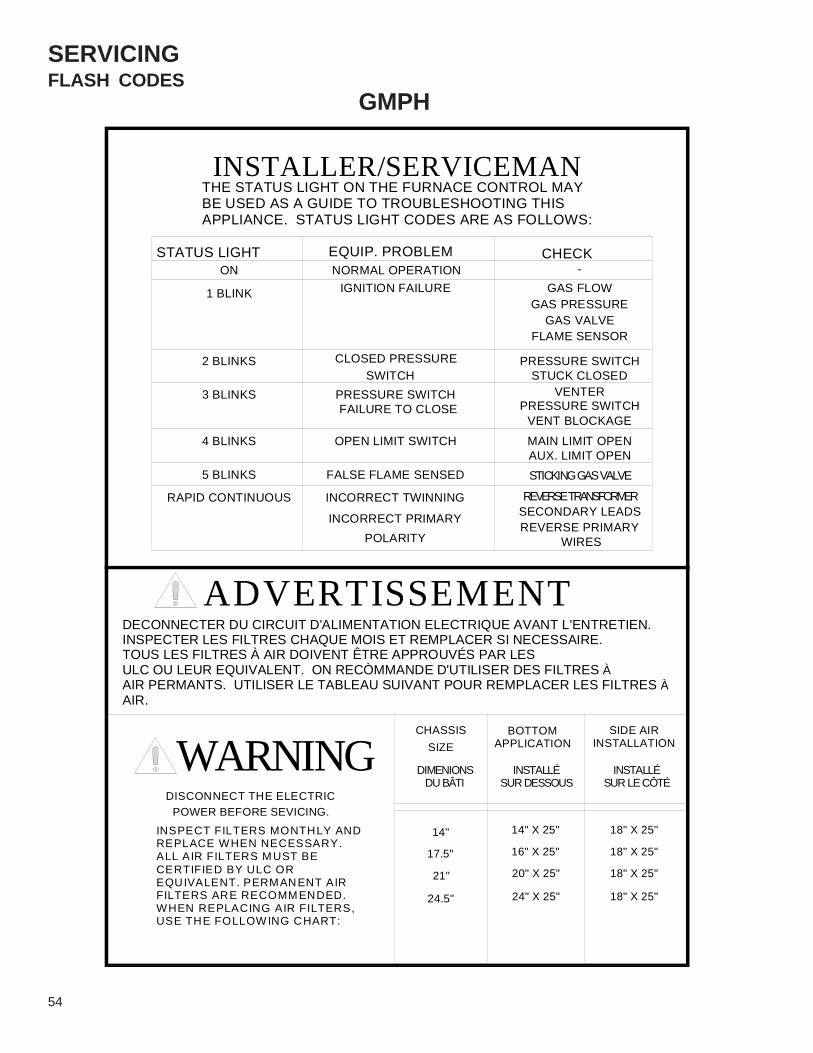
54
SERVICING
GMPHFLASH CODES
POLARITY
FALSE FLAME SENSED
OPEN LIMIT SWITCH
FAILURE TO CLOSEPRESSURE SWITCH
CLOSED PRESSURE
EQUIP. PROBLEMNORMAL OPERATION
IGNITION FAILURE
INCORRECT PRIMARY
INCORRECT TWINNING
3 BLINKS
5 BLINKS
4 BLINKS
STATUS LIGHTON
2 BLINKS
1 BLINK
SWITCHVENTER
SECONDARY LEADSREVERSE PRIMARY
WIRES
REVERSE TRANSFORMER
STICKING GAS VALVE
PRESSURE SWITCHVENT BLOCKAGE
AUX. LIMIT OPENMAIN LIMIT OPEN
GAS FLOW
GAS VALVE
STUCK CLOSEDPRESSURE SWITCH
FLAME SENSOR
GAS PRESSURE
CHECK-
CHASSIS
18" X 25"
18" X 25"
24" X 25"
20" X 25"
24.5"
21"
SIDE AIRINSTALLATION
18" X 25"
18" X 25"
SIZE
16" X 25"
14" X 25"
17.5"
14"
BOTTOMAPPLICATION
INSTALLER/SERVICEMANTHE STATUS LIGHT ON THE FURNACE CONTROL MAYBE USED AS A GUIDE TO TROUBLESHOOTING THISAPPLIANCE. STATUS LIGHT CODES ARE AS FOLLOWS:
DECONNECTER DU CIRCUIT D'ALIMENTATION ELECTRIQUE AVANT L'ENTRETIEN.INSPECTER LES FILTRES CHAQUE MOIS ET REMPLACER SI NECESSAIRE.TOUS LES FILTRES À AIR DOIVENT ÊTRE APPROUVÉS PAR LESULC OU LEUR EQUIVALENT. ON RECÒMMANDE D'UTILISER DES FILTRES ÀAIR PERMANTS. UTILISER LE TABLEAU SUIVANT POUR REMPLACER LES FILTRES ÀAIR.
DISCONNECT THE ELECTRICPOWER BEFORE SEVICING.
INSPECT FILTERS MONTHLY ANDREPLACE WHEN NECESSARY.ALL AIR FILTERS MUST BE CERTIFIED BY ULC OR EQUIVALENT. PERMANENT AIRFILTERS ARE RECOMMENDED.WHEN REPLACING AIR FILTERS,USE THE FOLLOW ING CHART:
RAPID CONTINUOUS
INSTALLÉSUR DESSOUS
INSTALLÉSUR LE CÔTÉ
DIMENIONSDU BÂTI
ADVERTISSEMENT
WARNING

SERVICING
55
GSUFLASH CODES
STUCK CLOSED
FLAME SENSOR
GAS PRESSURE
MAIN LIMIT OPEN
PRESSURE SWITCH
GAS VALVE STICKING
STATUS LIGHT
5 BLINKS
4 BLINKS
3 BLINKS
2 BLINKS
1 BLINK
ON
FALSE FLAME SENSED
OPEN LIMIT SWITCH
NORMAL OPERATION
CLOSED
IGNITION FAILURE
EQUIP. PROBLEM
PRESSURE SWITCH
GAS FLOW
GAS VALVE
CHECK
FAILURE TO CLOSEPRESSURE SWITCH
LOW FIRE
---
6 BLINKS
RAPID CONTINOUS
NO LIGHT IGNITION CONTROL FAILURE CHECK FUSE & TRANSFORMERCHECK FOR 115V at Control Board
18" X 25"
18" X 25"
INSTALLATION
18" X 25"
18" X 25"
SIDE AIR
21"
24.5" 24" X 25"
20" X 25"
SIZE
17.5"
14"
DU BATIDIMENSIONS
CHASSISAPPLICATION
16" X 25"
14" X 25"
BOTTOM
INSTALLÉSUR DESSOUS
INSTALLÉSUR LE CÔTÉ
ADVERTISSEMENTDECONNECTER DU CIRCUIT D'ALIMENTATION ELECTRIQUE AVANT L'ENTRETIEN.INSPECTER LES FILTRES CHAQUE MOIS ET REMPLACER SI NECESSAIRE.TOUS LES FILTRES À AIR DOIVENT ÊTRE APPROUVÉS PAR LESULC OU LEUR EQUIVALENT. ON RECÒMMANDE D'UTILISER DES FILTRES ÀAIR PERMANTS. UTILISER LE TABLEAU SUIVANT POUR REMPLACER LES FILTRES ÀAIR.
INSTALLER/SERVICEMANTHE STATUS LIGHT ON THE FURNACE CONTROL MAYBE USED AS A GUIDE TO TROUBLESHOOTING THISAPPLIANCE. STATUS LIGHT CODES ARE AS FOLLOWS:
WARNINGDISCONNECT THE ELECTRIC
POWER BEFORE SEVICING.
INSPECT FILTERS MONTHLY ANDREPLACE WHEN NECESSARY.ALL AIR FILTERS MUST BE CERTIFIED BY ULC OR EQUIVALENT. PERMANENT AIRFILTERS ARE RECOMMENDED.WHEN REPLACING AIR FILTERS,USE THE FOLLOWING CHART:
VENT BLOCKAGEPRESSURE SWITCH
VENTER MOTOR
PRESSURE PORT TAP STOPPED UP
FAILURE TO CLOSEPRESSURE SWITCH
HIGH FIRE
VENT BLOCKAGEPRESSURE SWITCH
VENTER MOTOR
PRESSURE PORT TAP STOPPED UP
SWAP L1 & L2 LEADS SWAP SEC. TRANSFORMER LEADS CHECK POLARITY
INCORRECT TWINNING

56
SERVICINGS-14 CHECKING FLAME SENSORA flame sensing device is used in conjunction with the igni-tion control module to prove combustion. If proof of flame isnot present the control will de-energize the gas valve and"retry" for ignition or lockout.The following drawing illustrated from a bottom view, theapproximate distances for the ignitor and flame sensor tothe gas inshot burner. This may vary on different models.You will note they are in the main burner stream.
1/4± .1/16
3/8" ± .1/16"
IGNITOR FLAME SENSOR
Models with Integrated IgnitionControl & Flame Sensor Probe
1. Disconnect the flame sensor wire from the sensor ter-minal.
2. Connect a micro-amp meter in series with this wire andthe sensor terminal. See next illustration.
3. Be sure the negative side of the meter is connected tothe wire and the positive side of the meter is to sensorterminal.
2.0Digital Meter
DC
FLAME SENSOR
WIRE FROM CONTROL BOARD
4. Place the unit into a heating cycle.5. As soon as flame is established a micro-amp reading
should be evident once proof of flame (micro-amp read-ing) is established, the hot surface ignitor will be de-energized.
6. The Integrated Ignition controls will have 1 to 4 micro-amps. If the micro-amp reading is less .8uA (micro-ampDC). Check for high resistance wiring connections, sen-sor to burner gap, dirty flame sensor, or poor grounding.
7. Clean flame sensor with steel wool or emery cloth be-fore replacing any components. DO NOT use sandpa-per. See note below.
NOTE: Contaminated fuel or combustion air can create anearly invisible coating on the flame sensor. This coatingworks as an insulator causing a loss in the flame sensesignal. If this situation occurs the flame sensor must becleaned with steel wool or emery cloth.

SERVICING
57
S-15 CHECKING MAIN BURNERSThe main burners are used to provide complete combustionof various fuels in a limited space, and transfer this heat ofthe burning process to the heat exchanger.Proper ignition, combustion, and extinction are primarily dueto burner design, orifice sizing, gas pressure, primary andsecondary air, vent and proper seating of burners.We have used several in shot burner designs over the yearsand illustrated in the following illustrations.
.023" - .027"
(Beckett Burner - New Style)
In checking main burners, look for signs of rust, oversizedand undersized carry over ports restricted with foreign ma-terial, etc, refer to previous drawing.Other older main burners (shown below) should not needadjustment in most instances. However, burner air shuttersare provided should adjustment be necessary. After thefurnace has been in operation for at least five (5) minutesloosen the air shutter locking screws and close theshutter until yellow tipped flames appear. Now slowlyopen the shutter until the yellow disappears. Retightenthe locking screw.

58
WIRING DIAGRAMS
Wiring is subject to change. Always refer to the wiring diagram on the unit for the most up-to-date wiring.
HIGH VOLTAGE!DISCONNECT ALL POWER BEFORE SERVICING OR INSTALLING THISUNIT. MULTIPLE POWER SOURCES MAY BE PRESENT. FAILURE TODO SO MAY CAUSE PROPERTY DAMAGE, PERSONAL INJURY OR DEATH.
GMTH, GMT
NO
TE:
THE
LEA
DS
FR
OM
TH
E M
OTO
RM
AY B
E C
HAN
GED
TO
TH
ER
EQ
UIR
ED S
PEE
D.
*MED
-LO
- O
RAN
GE
*LO
W -
RED
*HI -
BLA
CK
*MED
- BL
UE
HEAT
IDBR
1
SO
G W
PS1
RLSPV
R
IDBR
1
PS2
ROS
PVR
HSIR
IDBR
2
ROS
GV
FUSE
HSI
IDBR
2 HSIR
COO
L
C
P.V
.
I.D.B
.
DS
115
/ 60
/ 1PO
WER
SUP
PLY
ROS
98
7
32
65
1 4
B
P
GV
PRO
S
BL
G
W
DS
PRO
SP
ROS
Y
PPS
2SO
PS1
Y
RLS
P
CAP
ACIT
OR
FS
BR
G
BR
HIG
H
IDB
OR
W B
W
W
W
BL LOW
MED
R
B
B
T'S
TAT
TO 1
15/1
/60 G
B
POW
ER S
UPP
LY
CO
ND
ENSI
NG
UN
IT
CH
ASSI
S G
RO
UN
DFR
OM
FU
RN
ACE
R24
V
BL R
BR
FS
LIMIT
GVPSO
PSI
LIMIT
W
WW G R
YG R
W G
TWIN
HEA
T
NEU
TRAL
S
IND
L2
FS
HSIM2
M1
COO
L
P.V
.M
OTO
R
HSI
BLPR
ITR
ANS
LS
LIM
IT S
WIT
CH
PVR
PO
WER
VE
NT
RE
LAY
PS1
PR
ES
SUR
E S
WIT
CH
, FIR
E
RO
S R
OLL
OU
T SW
ITC
HSO
ST
ACK
OV
ERTE
MP
SW
ITC
H
PV
PO
WER
VEN
TOR
PS2
PR
ES
SUR
E S
WIT
CH
, CO
MB
. BO
X
FS F
LAM
E SE
NSO
RG
V G
AS V
ALV
E
HS
IR
HO
T S
UR
FAC
E IG
NTI
ON
REL
AY
IDB
R1
IND
OO
R B
LOW
ER
HE
AT
RE
LAY
DS
DO
OR
SW
ITC
HC
OM
PON
ENT
LEG
EN
D
HS
I H
OT
SU
RFA
CE
IGN
ITO
R
IDB
IN
DO
OR
BLO
WE
R
IDB
R2
IND
OO
R B
LOW
ER
CO
OL
RE
LAY
WIR
ING
F
IELD
INST
ALLE
D P
OW
ER
F
IELD
INST
ALLE
D C
ON
TRO
L
L
INE
VO
LTAG
E
L
OW
VO
LTAG
E
W
IRE
SPLI
CE
M
AR
KED
TER
MIN
AL
U
NM
AR
KED
TER
MIN
AL
BR
BR
OW
N
PK
PIN
KPU
P
UR
PLE
R
RED
W
WH
ITE
Y
YELL
OW
G
GR
EEN
O
OR
ANG
E
WIR
E C
OD
E
B
BLAC
KBL
BL
UE
(1)
(4)
(7)
(8 (6)
(9)
(5)
(2)
(0)
(3)
NO
TES
1. R
EPLA
CE
ME
NT
WIR
E M
UST
B
E TH
E SA
ME
SIZ
E A
ND
TY
PE
OF
INSU
LATI
ON
AS
OR
IGIN
AL.(1
05ºF
).
2. W
ARN
ING
: C
ABIN
ET M
US
T BE
P
ERM
ANE
NTL
Y G
RO
UN
DED
AN
D
CO
NFO
RM
TO
N.E
.C. &
LO
CAL
CO
DE
S.
3. T
HE
LEA
DS
FRO
M T
HE
MO
TOR
MA
Y
BE
CH
AN
GED
TO
REQ
UIR
ED S
PEE
D.
B149
33-2
23

WIRING DIAGRAMSHIGH VOLTAGE!DISCONNECT ALL POWER BEFORE SERVICING OR INSTALLING THISUNIT. MULTIPLE POWER SOURCES MAY BE PRESENT. FAILURE TODO SO MAY CAUSE PROPERTY DAMAGE, PERSONAL INJURY OR DEATH.
Wiring is subject to change. Always refer to the wiring diagram on the unit for the most up-to-date wiring.59
GMNT
LS
LIM
IT S
WIT
CH
PVR
P
OW
ER V
EN
T R
ELA
Y
PS1
PR
ESS
UR
E SW
ITC
H, F
IRE
RO
S R
OLL
OU
T SW
ITC
HSO
ST
ACK
OV
ER
TEM
P S
WIT
CH
PV
PO
WER
VEN
TOR
PS2
PR
ESS
UR
E SW
ITC
H, C
OM
B. B
OX
FS F
LAM
E SE
NSO
RG
V G
AS V
ALVE
HS
IR
HO
T S
UR
FAC
E IG
NTI
ON
REL
AY
IDBR
1 IN
DO
OR
BLO
WE
R H
EAT
REL
AY
DS
DO
OR
SW
ITC
HC
OM
PO
NEN
T LE
GE
ND
HS
I H
OT
SU
RFA
CE
IGN
ITO
R
IDB
IN
DO
OR
BLO
WE
R
IDBR
2 IN
DO
OR
BLO
WE
R C
OO
L R
ELA
Y
WIR
ING
F
IELD
INST
ALLE
D P
OW
ER
F
IELD
INST
ALLE
D C
ON
TRO
L
L
INE
VOLT
AGE
L
OW
VO
LTAG
E
W
IRE
SPL
ICE
M
AR
KE
D T
ER
MIN
AL
U
NM
AR
KE
D T
ER
MIN
AL
BR
BR
OW
N
PK
PIN
KPU
P
UR
PLE
R
RE
DW
W
HIT
EY
YE
LLO
W
G
GR
EEN
O
OR
ANG
E
WIR
E C
OD
E
B
BLAC
KBL
BL
UE
(1)
(4)
(7)
(8)
(6)
(9)
(5)
(2)
(0)
(3)
NO
TES
1. R
EPLA
CE
ME
NT
WIR
E M
UST
B
E T
HE
SA
ME
SIZ
E A
ND
TY
PE
OF
INSU
LATI
ON
AS
OR
IGIN
AL.(1
05ºF
).
2. W
ARN
ING
: C
ABIN
ET M
US
T B
E
PE
RM
AN
ENTL
Y G
RO
UN
DED
AN
D
CO
NFO
RM
TO
N.E
.C. &
LO
CA
L C
OD
ES.
3. T
HE
LEA
DS
FRO
M T
HE
MO
TOR
MA
Y
BE
CH
AN
GED
TO
REQ
UIR
ED S
PEE
D.
B149
33-2
26
HEAT
IDBR
1
SO
G W
PS
RLSPV
R
IDBR
1
ROS
ROS
PVR
HSIR
IDBR
2
ROS
GV
FUSE
HSI
IDBR
2
HSI
R
COO
L
C
P.V.
I.D.B
.
DS
115
/ 60
/ 1PO
WER
SUP
PLY
ROS
98
7
32
65
1 4
B
P
GV
PRO
S
BLHS
I
G
WP
.V.
MO
TOR
DS
PRO
SP
ROS
Y
PRO
SSO
PS
Y
RLS
P
CA
PAC
ITO
R
FS
BR
G
BR
HIG
H
IDB
OR
W B
W
W
W
BL
LOW
MED
RB
B
T'S
TAT
TO 1
15/1
/60
GB
PO
WE
R S
UP
PLY
CO
ND
EN
SIN
GU
NIT
CH
ASS
IS G
RO
UN
DFR
OM
FU
RN
AC
E
R24
V
BL RBL
BR
FS
LIMIT
GVPSO
PSI
LIMIT
W
WW G R
YG
R
W G
TWIN
HEA
T
NEU
TRA
LS
IND
L2TR
ANS
PRI
FS
HSI
M2M1
COO
L

60
WIRING DIAGRAMS
Wiring is subject to change. Always refer to the wiring diagram on the unit for the most up-to-date wiring.
HIGH VOLTAGE!DISCONNECT ALL POWER BEFORE SERVICING OR INSTALLING THISUNIT. MULTIPLE POWER SOURCES MAY BE PRESENT. FAILURE TODO SO MAY CAUSE PROPERTY DAMAGE, PERSONAL INJURY OR DEATH.
GMNT
LS
LIM
IT S
WIT
CH
PVR
P
OW
ER V
EN
T R
ELA
Y
PS1
PR
ESS
UR
E SW
ITC
H, F
IRE
RO
S
RO
LLO
UT
SWIT
CH
SO
STAC
K O
VER
TEM
P S
WIT
CH
PV
PO
WER
VEN
TOR
PS2
PR
ESS
UR
E SW
ITC
H, C
OM
B. B
OX
FS F
LAM
E SE
NSO
RG
V G
AS V
ALVE
HS
IR
HO
T S
UR
FAC
E IG
NTI
ON
REL
AY
IDBR
1 IN
DO
OR
BLO
WE
R H
EAT
REL
AY
DS
DO
OR
SW
ITC
H
CO
MPO
NE
NT
LEG
EN
D
HS
I H
OT
SU
RFA
CE
IGN
ITO
R
IDB
IN
DO
OR
BLO
WE
R
IDBR
2 IN
DO
OR
BLO
WE
R C
OO
L R
ELA
Y
WIR
ING
F
IELD
INST
ALLE
D P
OW
ER
F
IELD
INST
ALLE
D C
ON
TRO
L
L
INE
VO
LTAG
E
L
OW
VO
LTAG
E
W
IRE
SPLI
CE
M
AR
KED
TER
MIN
AL
U
NM
AR
KED
TER
MIN
AL
BR
BR
OW
N
PK
PIN
KPU
P
UR
PLE
R
RED
W
WH
ITE
Y
YELL
OW
G
GR
EEN
O
OR
ANG
E
WIR
E C
OD
E
B
BLAC
KBL
BL
UE
(1)
(4)
(7)
(8)
(6)
(9)
(5)
(2)
(0)
(3)
NO
TES
1. R
EPLA
CE
ME
NT
WIR
E M
UST
B
E TH
E SA
ME
SIZ
E A
ND
TY
PE
O
F IN
SULA
TIO
N A
S O
RIG
INAL
.(105
ºF).
2. W
ARN
ING
: C
ABIN
ET M
UST
BE
P
ERM
ANEN
TLY
GR
OU
ND
ED A
ND
C
ON
FOR
M T
O N
.E.C
. & L
OC
AL C
OD
ES.
3. T
HE
LEA
DS
FRO
M T
HE
MO
TOR
MA
Y
BE
CH
AN
GED
TO
REQ
UIR
ED S
PEE
D.
B149
33-2
27
HEA
TID
BR1
SO
G W
PS1
RLSPV
R
IDBR
1
ROS
PVR
HSIR
IDBR
2
ROS
GV
FUSE
HSI
IDBR
2
HSIR
CO
OL
C
P.V.
I.D.B
.
DS
115
/ 60
/ 1PO
WE
R SU
PPLY
RO
SAL
SRO
S
98
7
32
65
1 4
B
PG
VP
ROS
BLHS
I
G
W
DS
PRO
SP
ROS
Y
PSO
PS1
Y
RLS
P
CA
PAC
ITO
R
FS
BR
G
BR
HIG
H
IDB
OR
W B
W
W
W
BL LOW
MED
R
B
B
T'S
TAT
TO 1
15/1
/60
GB
PO
WE
R S
UP
PLY
CO
ND
EN
SIN
GU
NIT
CH
ASS
IS G
RO
UN
DFR
OM
FU
RN
AC
E
R24
V
BL RBL
BR
FS
LIMIT
GVPSO
PSI
LIMIT
W
WW G R
YG
R
W G
TWIN
HEAT
NEU
TRAL
S
IND
L2TR
ANS
PRI
FS
HSIM2
M1
COOL
ALS
PRO
S
P.V
.M
OTO
R
ALS
AU
XILI
AR
Y LI
MIT
SW
ITC
H

WIRING DIAGRAMSHIGH VOLTAGE!DISCONNECT ALL POWER BEFORE SERVICING OR INSTALLING THISUNIT. MULTIPLE POWER SOURCES MAY BE PRESENT. FAILURE TODO SO MAY CAUSE PROPERTY DAMAGE, PERSONAL INJURY OR DEATH.
Wiring is subject to change. Always refer to the wiring diagram on the unit for the most up-to-date wiring.61
1. R
EPLA
CEM
ENT
WIR
E M
UST
B
E TH
E S
AME
SIZE
AN
D T
YP
E
OF
INSU
LATI
ON
AS
OR
IGIN
AL
(1
05°C
).
2. W
ARN
ING
CA
BIN
ET
MU
ST
BE
P
ER
MA
NEN
TLY
GR
OU
ND
ED
AN
D
CO
NFO
RM
TO
N.E
.C. &
LO
CA
L
CO
DES
.
3. A
LL U
NU
SED
MO
TOR
S
PEED
LEA
DS
GE
T
PLA
CE
D O
N M
1, M
2 O
R C
AP
PE
D.
NO
TE:
THE
LEA
DS
FRO
M T
HE
MO
TOR
MAY
BE
CH
ANG
ED T
O T
HE
RE
QU
IRED
SP
EED
.
NO
TES:
WIR
ING
CO
DE
FAC
TOR
Y W
IRIN
GH
IGH
VO
LTA
GE
LOW
VO
LTA
GE
B485
78-0
2*M
ED-L
O -
OR
ANG
E*L
OW
- R
ED
*HI -
BLA
CK
*MED
- BL
UE
98
7
32
65
1 4
B
P
GV
PRO
S
BL
G
W
DS
PRO
SP
ROS
Y
PPS
2SO
PS1
Y
RLS
P
CAP
ACIT
OR
FS
BR
G
BR
HIGH
IDB
OR
W B
W
W
W
BL LOW
MED
R
B
B
T'ST
AT
TO 1
15/1
/60 G
B
POW
ER S
UPP
LY
CO
ND
ENSI
NG
UN
IT
CH
ASSI
S G
RO
UN
DFR
OM
FU
RN
ACE
R24
V
BL R
BR
FS
LIMIT
GVPSO
PSI
LIMIT
W
WW G R
YG R
W G
TWIN
HEA
T
NEU
TRAL
S
IND
L2
FS
HSI
M2
M1
COO
L
P.V
.M
OTO
R
HSI
BLPR
ITR
ANS
HEAT
IDBR
1
SO
G W
PS1
RLSPV
R
IDBR
1
PS2
ROS
PVR
HSIR
IDBR
2
ROS
GV
FUSE
HSI
IDBR
2 HSIR
COO
L
P.V.
I.D.B
.
DS
115
/ 60
/ 1PO
WER
SUP
PLY
ROS
FRS
PFC
FS
HSI
DS
GV
ICB
LS
MC
P
S
TR
P
V
IDB
ID
BR
P
VRC
R
H
R
ALS
A
UX
. LIM
IT S
WIT
CH
BLW
R. D
OO
R S
WIT
CH
PO
WE
R F
AC
TOR
TR
ANS.
FLAM
E S
ENSO
RFL
AME
RO
LL-O
UT
SWIT
CH
GAS
VAL
VEH
OT
SU
RFA
CE
IGN
ITO
RIG
NIT
ION
CO
NTR
OL
BO
AR
DM
AIN
LIM
IT S
WIT
CH
MO
TOR
CO
NTR
OLL
ER
PR
ESS
UR
E SW
ITC
HTR
ANS
FOR
ME
RP
OW
ER
VEN
TER
IND
OO
R B
LOW
ER
IND
OO
R B
LWR
RE
LAY
PO
WE
R V
ENT
RE
LAY
CO
OL
REL
AY
HEA
T R
ELA
Y
WIR
E C
OD
E
B
BLAC
KBL
BL
UE
BR
BR
OW
NG
G
REE
NO
O
RAN
GE
PK
PIN
KPU
P
UR
PLE
R
RED
W
WH
ITE
Y
YELL
OW
(1)
(4)
(7)
(8 (6)
(9)
(5)
(2)
(0)
(3)
GMNT B SERIES

62
WIRING DIAGRAMS
Wiring is subject to change. Always refer to the wiring diagram on the unit for the most up-to-date wiring.
HIGH VOLTAGE!DISCONNECT ALL POWER BEFORE SERVICING OR INSTALLING THISUNIT. MULTIPLE POWER SOURCES MAY BE PRESENT. FAILURE TODO SO MAY CAUSE PROPERTY DAMAGE, PERSONAL INJURY OR DEATH.
GMNT B SERIES
LS
LIM
IT S
WIT
CH
PVR
PO
WER
VE
NT
RE
LAY
PS1
PR
ES
SUR
E S
WIT
CH
, FIR
E
RO
S R
OLL
OU
T SW
ITC
HSO
ST
ACK
OV
ERTE
MP
SW
ITC
H
PV
PO
WER
VEN
TOR
PS2
PR
ES
SUR
E S
WIT
CH
, CO
MB
. BO
X
FS F
LAM
E SE
NSO
RG
V G
AS V
ALV
E
HS
IR
HO
T S
UR
FAC
E IG
NTI
ON
REL
AY
IDB
R1
IND
OO
R B
LOW
ER
HE
AT
RE
LAY
DS
DO
OR
SW
ITC
H
CO
MPO
NEN
T LE
GE
ND
HS
I H
OT
SU
RFA
CE
IGN
ITO
R
IDB
IN
DO
OR
BLO
WE
R
IDB
R2
IND
OO
R B
LOW
ER
CO
OL
RE
LAY
WIR
ING
F
IELD
INST
ALLE
D P
OW
ER
F
IELD
INST
ALLE
D C
ON
TRO
L
L
INE
VO
LTAG
E
L
OW
VO
LTAG
E
W
IRE
SPLI
CE
M
AR
KED
TER
MIN
AL
U
NM
AR
KED
TER
MIN
AL
BR
BR
OW
N
PK
PIN
KPU
P
UR
PLE
R
RED
W
WH
ITE
Y
YELL
OW
G
GR
EEN
O
OR
ANG
E
WIR
E C
OD
E
B
BLAC
KBL
BL
UE
(1)
(4)
(7)
(8)
(6)
(9)
(5)
(2)
(0)
(3)
NO
TES
1. R
EPLA
CE
ME
NT
WIR
E M
UST
B
E TH
E SA
ME
SIZ
E A
ND
TY
PE
OF
INSU
LATI
ON
AS
OR
IGIN
AL.(1
05ºF
).
2. W
ARN
ING
: C
ABIN
ET M
US
T BE
P
ERM
ANE
NTL
Y G
RO
UN
DED
AN
D
CO
NFO
RM
TO
N.E
.C. &
LO
CAL
CO
DE
S.
3. T
HE
LEA
DS
FRO
M T
HE
MO
TOR
MA
Y
BE
CH
AN
GED
TO
REQ
UIR
ED S
PEE
D.
4. A
LL U
NU
SED
MO
TOR
LEA
DS
GET
PLA
CE
D
ON
M1
AND
M2
OR
CA
PPED
.
B149
33-2
34
ALS
AU
XILI
AR
Y L
IMIT
SW
ITC
H
HEAT
IDBR
1
SO
G W
PS1
RLSPV
R
IDBR
1
ROS
PVR
HSIR
IDBR
2
ROS
GV
FUSE
HSI
IDBR
2
HSIR
COO
L
P.V.
I.D.B
.
DS
115
/ 60
/ 1PO
WER
SUP
PLY
RO
SAL
SRO
S
45
6
89
7
23
1
RO
SG
VPHS
IBL
W
*MED
-LO
- O
RAN
GE
*LO
W -
RED
*HI -
BLA
CK
*MED
- BL
UE
ROS
ROS
PP
RO
S
PP
SOAL
SP
FS
LS
PS
B
YY
G
MO
TOR
P.V
.
R
BW
R
P
O
W
CAP
ACIT
OR
BR B
RIDB
G
*R
*BL
*O
*B
PO
WE
R S
UP
PLY
TO 1
15/1
/60
CO
ND
EN
SIN
G
BUN
IT
L2
FRO
M F
UR
NA
CE
BL
DS
G
W
BLR
B
T'S
TAT
Y
24V
R
W RGW G R
FS
W
GV
LIMIT
PSI
PSO
LIMIT
NEUT
RALS
PRI
TRA
NS
CH
ASS
IS G
RO
UN
D
G R
W
WTW
IN
FS
B
IND
HEAT
M1
M2 HSI
COO
L

WIRING DIAGRAMSHIGH VOLTAGE!DISCONNECT ALL POWER BEFORE SERVICING OR INSTALLING THISUNIT. MULTIPLE POWER SOURCES MAY BE PRESENT. FAILURE TODO SO MAY CAUSE PROPERTY DAMAGE, PERSONAL INJURY OR DEATH.
Wiring is subject to change. Always refer to the wiring diagram on the unit for the most up-to-date wiring.63
GMNTE
FS F
LAM
E SE
NS
OR
GV
GA
S V
ALVE
HS
IR
HO
T S
UR
FAC
E IG
NTI
ON
REL
AY
DS
DO
OR
SW
ITC
H
CO
MPO
NEN
T LE
GE
ND
HS
I H
OT
SU
RFA
CE
IGN
ITO
R
IDB
IN
DO
OR
BLO
WE
R
LS
LIM
IT S
WIT
CH
PVR
1 P
OW
ER V
EN
T R
ELA
Y, L
OW
FIR
E
PS1
PR
ESS
UR
E S
WIT
CH
, LO
W F
IRE
RO
S R
OLL
OU
T SW
ITC
HSO
ST
AC
K O
VER
TEM
P S
WIT
CH
PV
PO
WER
VEN
TOR
PS2
PR
ESS
UR
E S
WIT
CH
, HIG
H F
IRE
PFC
PO
WER
FA
CTO
R C
HO
KE
WIR
ING
F
IELD
INST
ALLE
D P
OW
ER
F
IELD
INST
ALLE
D C
ON
TRO
L
L
INE
VOLT
AGE
L
OW
VO
LTAG
E
W
IRE
SPLI
CE
M
AR
KED
TER
MIN
AL
U
NM
AR
KED
TE
RM
INA
L
BR
BR
OW
N
PK
PIN
KPU
P
UR
PLE
R
RE
DW
W
HIT
EY
Y
ELLO
W
G
GR
EEN
O
OR
AN
GE
WIR
E C
OD
E
B
BLA
CK
BL
BLU
E(1
)(4
)(7
)(8
)(6
)(9
)(5
)(2
)(0
)(3
)
NO
TES
1. R
EPLA
CE
ME
NT
WIR
E M
UST
B
E TH
E SA
ME
SIZ
E A
ND
TY
PE
OF
INSU
LATI
ON
AS
OR
IGIN
AL.(
105º
F).
2. W
AR
NIN
G:
CA
BIN
ET M
UST
BE
P
ERM
ANEN
TLY
GR
OU
ND
ED A
ND
C
ON
FOR
M T
O N
.E.C
. & L
OC
AL C
OD
ES.
3. P
OW
ER F
ACTO
RY
CH
OKE
PR
ESE
NT
O
NLY
ON
UN
ITS
WIT
H 3
/4 A
ND
1
HP
IND
OO
R B
LOW
ERS
.
B149
33-2
35
ALS
AU
XILI
AR
Y LI
MIT
SW
ITC
H
*MED
-LO
- O
RAN
GE
*LO
W -
RE
D
*HI -
BLA
CK
*MED
- B
LUE
GYLO YW2
W1R
FAN
LOW
HE
AT
LOW
CO
OL
HIG
H CO
OL
IDB
PS2HI
GH
SOLS
ROR
ORO
FUSE
HSI
R
FS
HIG
H HE
AT
PS1
RO
HSIR
HIG
H
PVR
2
GV
ALS
LOW
PVR1
C
HSI
PVR1
DS
LOW
MO
DEL
SPF
CNO
T AL
L
PVR2
POW
ER S
UPPL
Y11
5 / 6
0 / 1
PV
IDB
XFM
R
EAC
BL
24V
B W
FSALS
R
R
P
BR
R
PS
G
P
YY
LINE
XFMR
EAC
CIRC
HUM
HUM
XFMR
LINE
NOT
ALL
MO
DELS
TO 1
15/1
/60
POW
ER S
UPPL
Y
BG
W
PFC
HSI
W
HO
TN
EUTR
ALS
B
WB
W
R
B
G
HI
LOW
COM
BLP
GV
P
PP
LS
SO
BLO
PS
P
O
RO
S
RO
SP
RO
SRO
SP
P
W
IDB
PV
DS
XFM
R T
RA
NSF
OR
ME
R
PVR
2 P
OW
ER V
EN
T R
ELA
Y, H
IGH
FIR
E

64
WIRING DIAGRAMS
Wiring is subject to change. Always refer to the wiring diagram on the unit for the most up-to-date wiring.
HIGH VOLTAGE!DISCONNECT ALL POWER BEFORE SERVICING OR INSTALLING THISUNIT. MULTIPLE POWER SOURCES MAY BE PRESENT. FAILURE TODO SO MAY CAUSE PROPERTY DAMAGE, PERSONAL INJURY OR DEATH.
GMPN
*
12
3
45
6
78
9
*
1. R
EPLA
CEM
EN
T W
IRE
MU
ST
BE
TH
E S
AM
E SI
ZE A
ND
TY
PE
O
F IN
SU
LATI
ON
AS
OR
IGIN
AL
(1
05°C
).
2. W
ARN
ING
CAB
INET
MU
ST B
E
PER
MAN
EN
TLY
GR
OU
ND
ED A
ND
C
ON
FOR
M T
O N
.E.C
. & L
OC
AL
C
OD
ES.
THE
LEA
DS
FR
OM
TH
E M
OTO
RM
AY B
E C
HAN
GE
D T
O T
HE
RE
QU
IRE
D S
PEE
D.
* M
ED H
I - Y
ELLO
WM
ED L
OW -
ORA
NG
E
POW
ER
SU
PPL
YTO
115
/1/6
024
V
B
BP
.V.
MO
TOR G
W
G
BRBR
WIR
E C
OLO
R C
OD
E
B BL BR G OO
RAN
GE
GR
EEN
BR
OW
N
BLU
EB
LAC
KP
INK
PU
RP
LEW
HIT
EY
ELLO
WR
EDRYWPK
NO
TE:
P.V
.
I.D.B
.
NO
TES:
WIR
ING
CO
DE
FAC
TOR
Y W
IRIN
GH
IGH
VO
LTAG
ELO
W V
OLT
AGE
B
MED
R
HIG
H
B
LOW
BL
BL
115
/ 60
/ 1
HEAT
COO
L
LSR G W
PS
IDB
- IN
DOO
R BL
OW
ER
LS -
LIM
IT S
WIT
CH
DS -
DO
OR
SWIT
CH
PVR
- POW
ER V
ENT
RELA
YRO
S - R
OLLO
UT S
WIT
CH
GV
- GA
S VA
LVE
HSI -
HO
T SU
RFA
CE
IGNI
TOR
IDBR
2
IDBR
- IN
DOO
R BL
OW
ER R
ELAY
PV -
POW
ER V
ENTO
R
FS -
FLAM
E SE
NSO
R
PS
LS
DS
IDB
GV
FS
HSI
SO
W
COO
L
HEA
T
M1
M2
HSI
IND
NEU
TRAL
SPR
ITR
ANS
W G R
L2
W
W
R
LIMIT
PSI
PSO
GVFS
LIMIT
Y
R
R
Y
CAP
AC
ITO
R
P
BL
PVR
ROS
GV
IDBR
1
IDBR
2PV
R
HSIR
HOT
SUR
FAC
E IG
NITI
ON
REL
AY
HSI
FUSE
W G R
ROS
B
W
R
O
B
P
FS
TWIN
ROS
P
BL
PS -
PRE
SSUR
E SW
ITCH
SO -
STAC
K OV
ERTE
MP
SWIT
CH
W RGY
CO
ND
EN
SIN
GU
NIT
SO
T'S
TAT
W
R
G
HSIR
HSIR
POW
ER S
UPPL
Y
ROS
ROS
ROS
PP
P
IDBR
1
BL
ROS
P
ROS
FRO
M F
UR
NAC
EC
HAS
SIS
GR
OU
ND
(1)
(4)
(7)
(8)
(6)
(0)
(2)
(3)
(5)
(9)
B285
7804

WIRING DIAGRAMSHIGH VOLTAGE!DISCONNECT ALL POWER BEFORE SERVICING OR INSTALLING THISUNIT. MULTIPLE POWER SOURCES MAY BE PRESENT. FAILURE TODO SO MAY CAUSE PROPERTY DAMAGE, PERSONAL INJURY OR DEATH.
Wiring is subject to change. Always refer to the wiring diagram on the unit for the most up-to-date wiring.65
GMPE
12
3
45
6
78
9
POW
ER S
UPP
LY11
5/1/
60
{1.
RE
PLA
CE
ME
NT
WIR
E M
US
T
BE
TH
E S
AME
SIZ
E A
ND
TY
PE
O
F IN
SU
LATI
ON
AS
OR
IGIN
AL
(1
05°C
).
2. W
ARN
ING
CA
BIN
ET M
UST
BE
P
ER
MA
NE
NTL
Y G
RO
UN
DED
AN
D
CO
NFO
RM
TO
N.E
.C. &
LO
CAL
C
OD
ES
.
3. P
FC U
SED
ON
G
MP
E10
0 &
125
MO
DE
LS
ON
LY.
TO T
HER
MO
STAT
WH
ITE=
W1
BROW
N=W
2G
REEN
=GR
ED=R
YELL
OW
=Y
B25
5780
6
24V
P.V
.
WIR
E C
OLO
R C
OD
E
B BL
BR
G OO
RA
NG
EG
RE
EN
BR
OW
NB
LUE
BLA
CK
PIN
KP
UR
PLE
WH
ITE
YEL
LOW
RED
RYWPK
P.V
.
I.D.B
.
NO
TES
:W
IRIN
G C
OD
E
FAC
TOR
Y W
IRIN
GH
IGH
VO
LTA
GE
LOW
VO
LTA
GE
HIG
H V
OLT
AG
EFI
ELD
WIR
ING
B
L 1
L 2
LS
R G W1
PS
AL
IDB
- IN
DO
OR
BLO
WER
LS -
LIM
IT S
WIT
CH
HR
- HE
AT R
ELAY
PVR
- PO
WER
VEN
T RE
LAY
RO
S - R
OLL
OU
T SW
ITC
H
GV
- G
AS V
ALVE
HSI
- HO
T SU
RFA
CE
IGNI
TOR
IDBR
IDBR
- IN
DOO
R B
LOW
ER R
ELA
Y
PV -
POW
ER V
ENTO
R
FS -
FLAM
E SE
NSO
R
PS
LS
DS
IDB
LO
FS
HSI
ROS
CO
OL
HEA
T
M1
M2
HSI
IND
NEU
TRAL
S
W G R
L2
WR
ROS
ROS
R
P
PBL
PVR
ROS
RO
S
GV
PVR
ICB
- IN
TER
GR
ATED
CIR
CUIT
BO
ARD
HSI
FUSE
ALS
ROS
ROS
P
P
FS
TWIN
ROS
PS -
PR
ESSU
RE S
WIT
CH
CR
- CO
OL R
ELAY
OTC
OT1
OT2
OHUM
C1 C2W
1/W
2W
2E R Y1
Y/Y2 G
BL
J3J2
BLY
GY
RW
R
G
W
R
YY
P
P
O
B
W
W
B
B
W
W
B
W
BL
P
B
BL
ICB
MC
- M
OTO
R C
ONT
ROLL
ERTR
- TR
ANSF
OR
MER
ALS
- AU
XILI
ARY
LIM
IT S
WIT
CH
DS
- DO
OR
SW
ITC
H
MC
G
BL
O
31
2
4
COM
HI
GV
BR
BL
W
BR
BR
W2
B
BR
B
115V
PFC
IDBR
IDBR
PFC
DS
HEA
T
CO
OL
PFC
- PO
WER
-FAC
TOR
CH
OKE
TRA
NSF
OR
MER
W2R
HSI
R
HSI
R - H
OT
SURF
ACE
IGN
ITO
R R
ELAY
W2R
- W
2 R
ELAY
W2
REL
AY
SEE
NO
TE#3
W2R
6
27
TO CO
NDE
NSI
NG
UN
IT

66
WIRING DIAGRAMS
Wiring is subject to change. Always refer to the wiring diagram on the unit for the most up-to-date wiring.
HIGH VOLTAGE!DISCONNECT ALL POWER BEFORE SERVICING OR INSTALLING THISUNIT. MULTIPLE POWER SOURCES MAY BE PRESENT. FAILURE TODO SO MAY CAUSE PROPERTY DAMAGE, PERSONAL INJURY OR DEATH.
GMPE
FS F
LAM
E SE
NSO
R
GV
GAS
VAL
VE
DS
DO
OR
SW
ITC
H
CO
MPO
NEN
T LE
GE
ND
HS
I H
OT
SU
RFA
CE
IGN
ITO
RIC
B
IGN
ITIO
N C
ON
TRO
L BO
AR
DLS
LI
MIT
SW
ITC
H
IDB
IN
DO
OR
BLO
WE
R
PS
PR
ESSU
RE
SW
ITC
H
PVR
PO
WER
VE
NT
RE
LAY
CR
C
OO
L R
ELA
Y
PV
PO
WER
VEN
TOR
TR
TRAN
SFO
RM
ER
WIR
ING
F
IELD
INST
ALLE
D P
OW
ER
F
IELD
INST
ALLE
D C
ON
TRO
L
L
INE
VO
LTAG
E
L
OW
VO
LTAG
E
W
IRE
SPLI
CE
M
AR
KED
TER
MIN
AL
U
NM
AR
KED
TER
MIN
AL
BR
BR
OW
N
PK
PIN
KPU
P
UR
PLE
R
RED
W
WH
ITE
Y
YELL
OW
G
GR
EEN
O
OR
ANG
E
WIR
E C
OD
E
B
BLAC
KBL
BL
UE
NO
TES
1. R
EPLA
CE
ME
NT
WIR
E M
UST
B
E TH
E SA
ME
SIZ
E A
ND
TY
PE
OF
INSU
LATI
ON
AS
OR
IGIN
AL.(1
05ºF
).
2. W
ARN
ING
: C
ABIN
ET M
US
T BE
P
ERM
ANE
NTL
Y G
RO
UN
DED
AN
D
CO
NFO
RM
TO
N.E
.C. &
LO
CAL
CO
DE
S.
3. P
FC U
SED
ON
GM
PE10
0 &
125
MO
DEL
S
ON
LY.
B149
33-1
84
ALS
AU
XILI
AR
Y L
IMIT
SW
ITC
H
*MED
-LO
- O
RAN
GE
*LO
W -
RED
*HI -
BLA
CK
*MED
- BL
UE
IDB
R
IND
OO
R B
LOW
ER R
ELAY
W2
AL
PVR
PSLS
FUSE
L 1
PVR
IDBR
HSIR
COOL
IDBR
DS
HEAT
W2R
W2R
IDBR
ROS
HSI
GV
PFC
P.V
.
I.D.B
.
L 2
W1GR
ROS
ROS
ROS
BL
POW
ER S
UPPL
Y
RBL
B
ROS
BLLO CO
M
HI
P
P
GV
ROS
P
ROS
B
BRROS
PB
115/
1/60
DSW
G
B
WHS
I
FS
PS
BL
Y
P
ALS
Y
LSR
RP
O
89
7
W P.V
.
W
BL
115V
BBR
B
PFC
W
B
NEUT
RALS
IND
L2
#3SEE
NO
TE
J2
Y1
J3
GY/
Y2
FS
W
B
BL
R24
V
52
63
41TWIN
ICB
HEAT
HSI
M2M1
COO
L
OT1
O
OTC
EC1 C2 W2
W1/
W2
OHUM
OT2
COND
ENSI
NG
UNI
T
TOY
1 BL
3RE
LAY
2
BR 4
W2
IDB
W
MC
BR
G
WR
Y
TO T
HERM
OSTA
T
{
GW
RGW
FSR
FLA
ME
RO
LLO
UT
SW
ITC
H
MC
M
AST
ER
CO
NTR
OLL
ER
HR
H
EAT
REL
AY

WIRING DIAGRAMSHIGH VOLTAGE!DISCONNECT ALL POWER BEFORE SERVICING OR INSTALLING THISUNIT. MULTIPLE POWER SOURCES MAY BE PRESENT. FAILURE TODO SO MAY CAUSE PROPERTY DAMAGE, PERSONAL INJURY OR DEATH.
Wiring is subject to change. Always refer to the wiring diagram on the unit for the most up-to-date wiring.67
GMPH
FS F
LAM
E SE
NSO
RG
V G
AS V
ALVE
DS
DO
OR
SW
ITC
H
CO
MPO
NEN
T LE
GE
ND
HS
I H
OT
SU
RFA
CE
IGN
ITO
RIC
B I
NTE
GR
ATED
CIR
CU
IT B
OAR
D
LS
LIM
IT S
WIT
CH
IDB
IN
DO
OR
BLO
WE
R
PS
PR
ESSU
RE
SWIT
CH
PVR
PO
WER
VE
NT
RE
LAY
RO
S R
OLL
OU
T SW
ITC
H
PV
PO
WER
VEN
TOR
TR
TRAN
SFO
RM
ER
WIR
ING
F
IELD
INST
ALLE
D P
OW
ER
F
IELD
INST
ALLE
D C
ON
TRO
L
L
INE
VOLT
AGE
L
OW
VO
LTAG
E
W
IRE
SPLI
CE
M
AR
KED
TER
MIN
AL
U
NM
AR
KED
TER
MIN
AL
BR
BR
OW
N
PK
PIN
KPU
P
UR
PLE
R
RED
W
WH
ITE
Y
YELL
OW
G
GR
EEN
O
OR
ANG
E
WIR
E C
OD
E
B
BLAC
KBL
BL
UE
NO
TES
1. R
EPLA
CE
ME
NT
WIR
E M
UST
B
E TH
E SA
ME
SIZ
E A
ND
TY
PE
OF
INSU
LATI
ON
AS
OR
IGIN
AL.(1
05ºF
).
2. W
ARN
ING
: C
ABIN
ET M
UST
BE
P
ERM
ANEN
TLY
GR
OU
ND
ED A
ND
C
ON
FOR
M T
O N
.E.C
. & L
OC
AL C
OD
ES.
B149
33-1
75
ALS
AU
XILI
AR
Y LI
MIT
SW
ITC
H
IDBR
IN
DO
OR
BLO
WER
REL
AY
SO
STAC
K O
VER
ALS
PS
RLSPV
R
HSIR
ROS
ROSPV
R
ROS
HSIR
FUSE
IDBR
1
ROS
IDBR
2
GV
HSI
115
/ 60
/ 1PO
WER
SUP
PLY
IDBR
2
IDBR
1
COO
L
HEAT
I.D.B
.
P.V
.
G W
89
7
63
54
21
*
*
R
BR
BR
CAP
AC
ITO
R
GVPS
HSI
ROS
Y
PRO
S
Y
PROS
FS
PROS
PG
IDB
MED
IND
G
G B
MO
TOR
W
P.V.
BL
B
DS
R
LS
W B
P
ALS
O
W
W
RY
W
Y
B
RBL
BL
LIMITLIMIT
FSGV
PSOPSI
NEUT
RALS
L2TR
ANS
PRI
GW RO
PTIO
NAL
CON
DEN
SIN
G
TO 1
15/1
/60
POW
ER
SUP
PLY
B
UN
IT
Y
T'ST
AT
Y
FURN
ACE
CH
ASSI
S G
ND.
24V
BL
R
RG
GBL W
R
WTW
IN
FS
M1
HEAT HS
I
M2
COOL
LOW
HIG
H
RB
BL
B
TEM
P S
WIT
CH

68
WIRING DIAGRAMS
Wiring is subject to change. Always refer to the wiring diagram on the unit for the most up-to-date wiring.
HIGH VOLTAGE!DISCONNECT ALL POWER BEFORE SERVICING OR INSTALLING THISUNIT. MULTIPLE POWER SOURCES MAY BE PRESENT. FAILURE TODO SO MAY CAUSE PROPERTY DAMAGE, PERSONAL INJURY OR DEATH.
GMT & GMT A SERIES
*
12
3
45
6
78
9
*
THE
LEAD
S FR
OM
TH
E M
OTO
R M
AY B
E C
HAN
GED
TO
TH
E R
EQU
IRE
D S
PEED
.
1. R
EPLA
CEM
ENT
WIR
E M
UST
BE T
HE
SA
ME
SIZE
AN
D T
YPE
OF
INSU
LATI
ON
AS
OR
IGIN
AL
(105
°C.)
2. W
ARN
ING
CAB
INET
MU
ST B
EPE
RM
AN
EN
TLY
GR
OU
ND
ED
AN
DC
ON
FOR
M T
O N
.E.C
. & L
OC
ALC
OD
ES.
3. F
OR
MO
DEL
GM
T140
-5
SEE
FIG
#1.
4. A
LL U
NU
SED
MO
TOR
SPE
EDLE
ADS
GE
T PL
AC
ED O
NM
I AN
D M
2.
B405
7802
POW
ER
SU
PPL
YTO
115
/1/6
024
V
B
BP.
V.M
OTO
R G
W
G
BRBR
WIR
E C
OLO
R C
OD
E
B BL
BR
G OO
RAN
GE
GR
EEN
BR
OW
NB
LUE
BLA
CK
PIN
KPU
RPL
EW
HIT
EYE
LLO
WR
ED
RYWPK
P.V.
I.D.B
.
NO
TES:
WIR
ING
CO
DE
FAC
TOR
Y W
IRIN
GH
IGH
VO
LTAG
ELO
W V
OLT
AGE
B
MED
R
HIG
H
B
LOWBL
BL
HEAT
COO
L
LSR G W
PS
IDB
- IN
DOO
R BL
OW
ER
LS -
LIM
IT S
WIT
CH
DS
- DO
OR
SWIT
CH
PVR
- PO
WER
VEN
T RE
LAY
ROS
- RO
LLO
UT S
WIT
CH
GV
- GA
S VA
LVE
HSI
- HO
T SU
RFAC
E IG
NITO
R
IDBR
2
IDBR
- IN
DOO
R B
LOW
ER R
ELAY
PV -
POW
ER V
ENTO
R
FS -
FLAM
E SE
NSO
R
PS
LS
DS
IDB
GV
FS
HSI
W
COOL
HEAT
M1
M2
HSI
IND
NEUT
RAL
SPR
ITR
ANS
W G R
L2
W
WR
LIMIT
PSI
PSO
GVFS
LIMIT
ROS
Y
R
R
Y
CAP
AC
ITO
R
P
PVR
ROS
GV
IDBR
1
IDBR
2
PVR
HSI
FUSE
W G R
BL
ROS
ROS
B
W
BL
B
YY
R
R
O
B
P
FS
TWIN
P
BL
PS -
PRE
SSUR
E SW
ITCH
P
W RGY
Y
UN
ITT'
STA
T
G
HSIR HS
IR
FUR
NAC
E C
HAS
SIS
GN
D.
IDBR
1
POW
ER S
UPPL
Y
115
/ 60
/ 1
OPT
ION
AL
CO
ND
ENSI
NG
BL
HSI
R - H
OT
SURF
ACE
IGNI
TOR
REL
AY
(1)
(4)
(7)
(8)
(6)
(3)
(2)
(0)
(5)
(9)
NO
TE:
*MED
- BL
UE
*LO
W -
RE
D
*MED
-LO
- Y
ELL
OW
*MED
-HI -
OR
ANG
E
HEAT
M1
M2
COOL
BLR
B
25
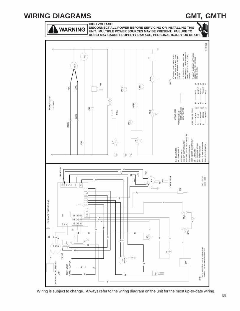
WIRING DIAGRAMSHIGH VOLTAGE!DISCONNECT ALL POWER BEFORE SERVICING OR INSTALLING THISUNIT. MULTIPLE POWER SOURCES MAY BE PRESENT. FAILURE TODO SO MAY CAUSE PROPERTY DAMAGE, PERSONAL INJURY OR DEATH.
Wiring is subject to change. Always refer to the wiring diagram on the unit for the most up-to-date wiring.69
GMT, GMTH
*
12
3
45
6
78
9
*
THE
LEA
DS
FR
OM
TH
E M
OTO
R M
AY B
E C
HA
NG
ED T
O T
HE
REQ
UIR
ED S
PEE
D.
1. R
EPLA
CEM
EN
T W
IRE
MU
STBE
TH
E SA
ME
SIZE
AN
D T
YPE
OF
INSU
LATI
ON
AS
OR
IGIN
AL(1
05°C
).
2. W
ARN
ING
CAB
INE
T M
UST
BE
PER
MAN
EN
TLY
GR
OU
ND
ED A
ND
CO
NFO
RM
TO
N.E
.C. &
LO
CAL
CO
DE
S.
3. M
OD
EL G
MT1
40-5
USE
S H
IGH
SPEE
D (B
LK) F
OR
HEA
TIN
G
AN
D C
OO
LIN
G.
B40
5780
1
POW
ER
SU
PPL
YTO
115
/1/6
024
V
B
BP
.V.
MO
TOR G
W
G
BRBR
WIR
E C
OLO
R C
OD
E
B BL BR G OO
RAN
GE
GR
EEN
BRO
WN
BLU
EBL
AC
KPI
NK
PUR
PLE
WH
ITE
YELL
OW
RE
DRYWPK
P.V.
I.D.B
.
NO
TES:
WIR
ING
CO
DE
FAC
TOR
Y W
IRIN
GH
IGH
VO
LTAG
ELO
W V
OLT
AGE
B
MED
R
HIG
H
B
LOWBL
BL
HEAT
COO
L
LSR G W
PS
IDB
- IND
OO
R BL
OW
ER
LS -
LIM
IT S
WIT
CH
DS -
DO
OR
SWIT
CH
PVR
- POW
ER V
ENT
RELA
Y
ROS
- ROL
LOU
T SW
ITCH
GV
- GA
S VA
LVE
HSI -
HO
T SU
RFA
CE
IGNI
TOR
IDBR
2
IDBR
- IN
DOO
R BL
OW
ER R
ELAY
PV -
POW
ER V
ENTO
R
FS -
FLAM
E SE
NSO
R
PS
LS
DS
IDB
GV
FS
HSI
W
COO
L
HEAT
M1
M2
HSI
IND
NEU
TRAL
SPR
ITR
ANS
W G R
L2
W
WR
LIMIT
PSI
PSO
GVFS
LIMIT
ROS
Y
R
R
Y
CAP
AC
ITO
R
P
PVR
ROS
GV
IDBR
1
IDBR
2
PVR
HSI
FUSE
W G R
BL
ROS
ROS
B
W
BL
B
YY
R
R
O
B
P
FS
TWIN
P
BL
PS -
PRE
SSUR
E SW
ITCH
P
W RGY
Y
UN
ITT'
STA
T
G
HSIR HS
IR
FUR
NAC
E C
HAS
SIS
GN
D.
IDBR
1
POW
ER S
UPPL
Y
115
/ 60
/ 1O
PTIO
NA
L C
ON
DEN
SIN
G
BL
HSIR
- HO
T SU
RFAC
E IG
NITO
R R
ELAY
(1)
(4)
(7)
(8)
(6)
(3)
(2)
(0)
(5)
(9)
NO
TE:
*ME
D -
BLU
E*L
OW
- R
ED
SEE N
OTE #
3
10
17

70
WIRING DIAGRAMS
Wiring is subject to change. Always refer to the wiring diagram on the unit for the most up-to-date wiring.
HIGH VOLTAGE!DISCONNECT ALL POWER BEFORE SERVICING OR INSTALLING THISUNIT. MULTIPLE POWER SOURCES MAY BE PRESENT. FAILURE TODO SO MAY CAUSE PROPERTY DAMAGE, PERSONAL INJURY OR DEATH.
GMT
FS F
LAM
E S
EN
SOR
GV
GA
S V
ALV
E
DS
DO
OR
SW
ITC
HC
OM
PON
ENT
LEG
EN
D
HS
I H
OT
SU
RFA
CE
IGN
ITO
RH
SIR
H
OT
SU
RFA
CE
IGN
ITO
R R
ELAY
LS
LIM
IT S
WIT
CH
IDB
IN
DO
OR
BLO
WE
R
PS
P
RE
SSU
RE
SWIT
CH
PV
R
POW
ER V
EN
T R
ELA
YR
OS
RO
LLO
UT
SWIT
CH
PV
P
OW
ER
VEN
TOR
WIR
ING
F
IELD
INST
ALLE
D P
OW
ER
F
IELD
INST
ALLE
D C
ON
TRO
L
L
INE
VOLT
AGE
L
OW
VO
LTA
GE
W
IRE
SPLI
CE
M
AR
KED
TE
RM
INA
L
U
NM
AR
KED
TER
MIN
AL
BR
B
RO
WN
PK
P
INK
PU
P
UR
PLE
R
RED
W
WH
ITE
Y
YEL
LOW
G
GR
EEN
O
OR
ANG
E
WIR
E C
OD
E
B
BLA
CK
BL
BLU
E
NO
TES
1. R
EPLA
CE
ME
NT
WIR
E M
US
T
BE
THE
SA
ME
SIZ
E A
ND
TY
PE
O
F IN
SULA
TIO
N A
S O
RIG
INA
L.(1
05ºF
).
2. W
ARN
ING
: C
ABIN
ET
MU
ST B
E
PER
MAN
ENTL
Y G
RO
UN
DE
D A
ND
C
ON
FOR
M T
O N
.E.C
. & L
OC
AL
CO
DE
S.
3. M
OD
EL G
MT1
40-5
US
ES H
IGH
SPE
ED
(BLK
)
FO
R H
EAT
ING
AN
D C
OO
LIN
G.
B149
33-2
30
IDBR
IN
DO
OR
BLO
WER
RE
LAY
WGRFU
SE
ROS
PSLS
PVR
ROS
IDBR
1
IDBR
2
HSIR
GV
I.D.B
.ID
BR2
PVR
IDBR
1
COO
L
HSIR
HSI
HEAT
115
/ 60
/ 1
POW
ER S
UPPL
Y
P.V
.
96
74
85
31
2
*
*
TRAN
S
HSI
P
ROS
PS
GV
P
Y
B
YLS
ROS
R
P
OP
TIO
NAL
CO
ND
ENS
ING
TO 1
15/1
/60
POW
ER
SU
PPLY
W
BL
BUN
IT
R
G
MO
TOR
P.V
.
R
W B
DS
W
O
W
W
R
BY
Y
B
G
BLBL
BL
24V
R
Y
T'ST
AT
YG RW
GW
R
BL
PSO
LIMIT
PSI
LIMIT
RG
NEUT
RAL
S
FS
FSGV
PRI
FUR
NAC
E C
HAS
SIS
GN
D.
WTW
IN
FS
CA
PAC
ITO
R
HIG
H
BRBR
GID
B
BL LOW
MED
R
B
B
IND
L2
HSI
M2M1
HEAT
COOL

WIRING DIAGRAMSHIGH VOLTAGE!DISCONNECT ALL POWER BEFORE SERVICING OR INSTALLING THISUNIT. MULTIPLE POWER SOURCES MAY BE PRESENT. FAILURE TODO SO MAY CAUSE PROPERTY DAMAGE, PERSONAL INJURY OR DEATH.
Wiring is subject to change. Always refer to the wiring diagram on the unit for the most up-to-date wiring.71
GMT, GMTH, & GMTH A SERIES
FS F
LAM
E SE
NSO
RG
V G
AS V
ALVE
DS
DO
OR
SW
ITC
HC
OM
PON
ENT
LEG
EN
D
HS
I H
OT
SU
RFA
CE
IGN
ITO
RH
SIR
H
OT
SU
RFA
CE
IGN
ITO
R R
ELA
Y
LS
LIM
IT S
WIT
CH
IDB
IN
DO
OR
BLO
WE
R
PS
PR
ESSU
RE
SWIT
CH
PVR
PO
WER
VE
NT
RE
LAY
RO
S
RO
LLO
UT
SWIT
CH
PV
PO
WER
VEN
TOR
WIR
ING
F
IELD
INST
ALLE
D P
OW
ER
F
IELD
INST
ALLE
D C
ON
TRO
L
L
INE
VO
LTAG
E
L
OW
VO
LTAG
E
W
IRE
SPLI
CE
M
AR
KED
TER
MIN
AL
U
NM
AR
KED
TE
RM
INA
L
BR
BR
OW
N
PK
PIN
KPU
P
UR
PLE
R
RED
W
WH
ITE
Y
YEL
LOW
G
GR
EEN
O
OR
ANG
E
WIR
E C
OD
E
B
BLA
CK
BL
BLU
E
NO
TES
1. R
EPLA
CE
ME
NT
WIR
E M
US
T
BE
THE
SA
ME
SIZ
E A
ND
TY
PE
O
F IN
SULA
TIO
N A
S O
RIG
INA
L.(1
05ºF
).
2. W
ARN
ING
: C
AB
INET
MU
ST B
E
PER
MA
NEN
TLY
GR
OU
ND
ED
AN
D
CO
NFO
RM
TO
N.E
.C. &
LO
CAL
CO
DE
S.
3. F
OR
MO
DE
L G
MT1
40-5
, SE
E FI
G. #
1.
4. A
LL U
NU
SED
MO
TOR
SPE
ED
LE
ADS
G
ET P
LAC
ED O
N M
1 A
ND
M2.
B149
33-2
31
IDBR
IN
DO
OR
BLO
WER
REL
AY
WGRFU
SE
RO
S
PS
LS
PVR
ROS
IDBR
1
IDBR
2
HSIR
GV
C
I.D.B
.ID
BR2
PVR
IDB
R1
COO
L
HSIR
HSI
HEAT
115
/ 60
/ 1
POW
ER S
UPPL
Y
P.V
.
*
*
56
89
23
4 71
BL
W
W HSI
BL
LS
GVP
B
PS
YY
ROS
P
ROS
R
P
G
MO
TO
RP
.V.
BW
DS
W
BL
R
YY
WR
B
R
LIMIT
PSIPSOGV
LIMIT
FS
NEU
TRA
LS
O
BR
CA
PAC
ITO
R
FS
BR
GID
B
HIGH
LOW
MED
B
BL
R
L2P
RITR
ANS
B
FUR
NAC
E C
HA
SSIS
GN
D.
UN
ITO
PTIO
NAL
CO
NDEN
SIN
G
B
POW
ER S
UPP
LYTO
115
/1/6
0
BL
T'ST
AT
G
BR
24V
Y
RGWY
R
W G
TW
IN
BL
W
FS
CO
OL
COO
L
FIG
# 1
G R
HEA
T
M1
M2
HSI
IND
HEA
T
M1
M2
BLR
B

72
WIRING DIAGRAMS
Wiring is subject to change. Always refer to the wiring diagram on the unit for the most up-to-date wiring.
HIGH VOLTAGE!DISCONNECT ALL POWER BEFORE SERVICING OR INSTALLING THISUNIT. MULTIPLE POWER SOURCES MAY BE PRESENT. FAILURE TODO SO MAY CAUSE PROPERTY DAMAGE, PERSONAL INJURY OR DEATH.
GMT, GMTH
FS F
LAM
E SE
NS
OR
GV
GA
S VA
LVE
DS
DO
OR
SW
ITC
HC
OM
PON
ENT
LEG
EN
D
HS
I H
OT
SU
RF
ACE
IGN
ITO
RH
SIR
H
OT
SU
RFA
CE
IGN
ITO
R R
ELA
Y
LS
LIM
IT S
WIT
CH
IDB
IN
DO
OR
BLO
WE
R
PS
P
RE
SSU
RE
SWIT
CH
PV
R
POW
ER V
EN
T R
ELA
YR
OS
RO
LLO
UT
SWIT
CH
PV
P
OW
ER
VEN
TOR
WIR
ING
F
IELD
INST
ALL
ED
PO
WE
R
FIE
LD IN
STA
LLE
D C
ON
TRO
L
L
INE
VO
LTAG
E
L
OW
VO
LTA
GE
W
IRE
SPL
ICE
M
AR
KE
D T
ERM
INA
L
UN
MA
RKE
D T
ERM
INA
L
BR
BR
OW
N
PK
PIN
KPU
P
UR
PLE
R
RE
DW
W
HIT
EY
Y
ELLO
W
G
GR
EEN
O
OR
ANG
E
WIR
E C
OD
E
B
BLA
CK
BL
BLU
E
NO
TES
1. R
EPL
AC
EM
EN
T W
IRE
MU
ST
BE
TH
E SA
ME
SIZ
E A
ND
TY
PE
OF
INSU
LATI
ON
AS
OR
IGIN
AL.
(105
ºF).
2. W
ARN
ING
: C
AB
INET
MU
ST B
E
PE
RM
ANE
NTL
Y G
RO
UN
DED
AN
D
CO
NFO
RM
TO
N.E
.C. &
LO
CAL
CO
DE
S.
B149
33-1
97
IDBR
IN
DO
OR
BLO
WE
R R
ELA
Y
WGRFU
SE
ROS
PSLS
PVR
ROS
IDBR
1
IDBR
2
HSIR
GV
C
I.D.B
.ID
BR2
PVR
IDBR
1
COO
L
HSIR
HSI
HEAT
115
/ 60
/ 1
POW
ER S
UPPL
Y
P.V
.
*
*
98
65
74
32
1
BLW
O
GV
PRO
S
ROS
P
W B
HSI
PS
B
W
G
MO
TO
RP.
V.
Y Y
LSR
P
R
W
FS
CA
PAC
ITO
R
BRBR
IDB
G
HIG
H
R
MED
LOWBL
B
TRAN
S
BL
DS
BG
BL
TO 1
15/1
/60
POW
ER
SU
PPLY
OP
TIO
NAL
CO
ND
ENS
ING
UN
ITT'
STAT
B
24V
Y
YW RG
B
W
YR
Y
RBL
FS
LIMIT
PSI
LIMIT
FS
GV
PSO
NEU
TRAL
SPR
I
TWIN
FUR
NAC
E C
HAS
SIS
GN
D.
R
G RW
BL
R
W G
B
IND
L2
HEA
T
M2M1
HSI
COO
L

WIRING DIAGRAMSHIGH VOLTAGE!DISCONNECT ALL POWER BEFORE SERVICING OR INSTALLING THISUNIT. MULTIPLE POWER SOURCES MAY BE PRESENT. FAILURE TODO SO MAY CAUSE PROPERTY DAMAGE, PERSONAL INJURY OR DEATH.
Wiring is subject to change. Always refer to the wiring diagram on the unit for the most up-to-date wiring.73
12
3
45
6
78
9
THE
LEA
DS
FR
OM
TH
E M
OTO
RM
AY B
E C
HAN
GE
D T
O T
HE
RE
QU
IRE
D S
PEE
D.
1. R
EPLA
CEM
EN
T W
IRE
MU
STBE
TH
E SA
ME
SIZE
AN
D T
YPE
OF
INS
ULA
TIO
N A
S O
RIG
INAL
(105
°C).
2. W
ARN
ING
CAB
INET
MU
ST B
EPE
RM
ANE
NTL
Y G
RO
UN
DED
AN
DC
ON
FOR
M T
O N
.E.C
. & L
OC
ALC
OD
ES.
POW
ER
SU
PPL
YTO
115
/1/6
024
V
B
BP
.V.
MO
TOR
BRBR
WIR
E C
OLO
R C
OD
E
B BL G OO
RAN
GE
(6)
GR
EEN
(8)
BLU
E (4
)B
LAC
K (1
)P
UR
PLE
(5)
WH
ITE
(0)
YEL
LOW
(3)
RED
(2)
RYWN
OTE
:
P.V
.
I.D.B
.
NO
TES:
WIR
ING
CO
DE
FAC
TOR
Y W
IRIN
GH
IGH
VO
LTAG
ELO
W V
OLT
AGE
BBL
HEAT
COO
L
LSR G W
PS
ALS
IDB
- IN
DOO
R BL
OW
ER
LS -
LIM
IT S
WIT
CH
DS -
DO
OR
SWIT
CH
PVR
- POW
ER V
ENT
RELA
Y
ROS
- ROL
LOUT
SW
ITC
H
GV
- GA
S VA
LVE
HSI -
HO
T SU
RFA
CE
IGNI
TOR
IDBR
2
IDBR
- IN
DOO
R BL
OW
ER R
ELAY
PV -
POW
ER V
ENTE
R
FS -
FLAM
E SE
NSO
R
PS
LS
DS
IDB
GV
FS
HSI
ROS
W
MED
LO
- O
RAN
GE
COOL
HEAT
M1
M2
HSI
IND
NEU
TRAL
SPR
ITR
ANS
W G R
L2
W
WR
YY
CAP
AC
ITO
R
P
BL
PVR
ROS
GV
IDBR
1
IDBR
2
PVR
HSI
FUSE
W G R
BL
B
W
RR
O
FS
TWIN
P
PS -
PRE
SSUR
E SW
ITCH
ALS
- AU
XILI
ARY
LIM
IT S
WIT
CH
W RGY
Y
UN
ITT'
STA
T
W
G
HSIR HS
IR
FUR
NAC
E C
HAS
SIS
GN
D.
IDBR
1
POW
ER S
UPPL
Y
115
/ 60
/ 1O
PTIO
NA
L C
ON
DEN
SIN
G
MED
-
BLUE
LO -
RED
MED
HI
- Y
ELLO
WHI
-
BLA
CK
ALS
FS
G
B255
78-0
4
(3)
(4)
(5)
(6)
(7)
(8) (9)
(1)
(2)
GPD, GDT, GDT A & B SERIES

74
WIRING DIAGRAMS
Wiring is subject to change. Always refer to the wiring diagram on the unit for the most up-to-date wiring.
HIGH VOLTAGE!DISCONNECT ALL POWER BEFORE SERVICING OR INSTALLING THISUNIT. MULTIPLE POWER SOURCES MAY BE PRESENT. FAILURE TODO SO MAY CAUSE PROPERTY DAMAGE, PERSONAL INJURY OR DEATH.
GSM
*
1. R
EPLA
CEM
EN
T W
IRE
MU
ST
BE T
HE
SAM
E S
IZE
AN
D T
YPE
OF
INSU
LATI
ON
AS
OR
IGIN
AL
(105
°C).
2. W
AR
NIN
G C
ABIN
ET
MU
ST B
EPE
RM
AN
ENT
LY G
RO
UN
DED
TO
CO
NFO
RM
TO
N.E
.C. &
LO
CA
LC
OD
ES.
OV
ER
CU
RR
EN
TP
RO
TEC
TIO
ND
EV
ICE
PO
WE
R S
UP
PLY
TO 1
15/1
/60
24V
B
P.V
.M
OTO
R G
G
BR B
R
WIR
E C
OLO
R C
OD
E
B BL BR G OO
RA
NG
EG
RE
ENBR
OW
NBL
UE
BLA
CK
PUR
PLE
WH
ITE
YELL
OW
RED
RYW
I.D.B
.
NO
TES
:W
IRIN
G C
OD
E
HIG
H V
OLT
AG
E
LOW
VO
LTA
GE
B
MED
BL
HIG
H
B
LOW
R
BL
L1L2
HEA
T - F
IRST
STA
GE
CO
OL
LSR G W
1
PS1
IDB
- IND
OO
R B
LOW
ER
LS -
LIM
IT S
WIT
CH
DS
- DO
OR
SW
ITCH
PVR
- PO
WER
VEN
T RE
LAY
RO
S - R
OLL
OU
T SW
ITCH
GV
- G
AS V
ALVE
HSI
- HO
T SU
RFA
CE IG
NIT
OR
IDBR
(ON
IGM
)
IDBR
- IN
DO
OR
BLO
WER
REL
AY
PV -
POW
ER V
ENTE
R
FS -
FLAM
E SE
NSO
R
PS1
LS
DS
IDB
HSI
SO
W
COO
L
HT. M
ED
HT. L
O
HSI
IND
LO
NEUT
RALS
PRI
TRAN
S
G R
L2
W
W
R
Y
P
R
R
Y
THER
MO
STAT
CA
PA
CIT
OR
P
SO
IGM
IGM
IGM
- IG
NIT
ION
MO
DUL
E
HSI
FUSE
BR G R
BLFU
RNAC
E C
HAS
SIS
GRO
UND
.
B
W
BL
B
YY
RR
PP
(ON
IGM
)
PVR
(ON
IGM
)
SO -
STAC
K O
VERT
EMP
PS3
- PRE
SSU
RE S
WIT
CH
CO
MB.
BO
X
C
DS
BL
PCB
- PR
INTE
D C
IRCU
IT B
OAR
D
GV
RO
SP
RO
SPS
3
PS3
FS
RO
O
P
PS2
BL
BL
R
O
O
B
IND
HI
R
B
W
W1
W
PS1
- PRE
SSU
RE S
WIT
CH
LO F
IRE
PS2
- PRE
SSU
RE S
WIT
CH
HI F
IRE
IGM
IGM
LO S
PD.
HI S
PD
PV
IGM
HEA
T - S
ECO
ND
STA
GE
W2
PVR
(ON
IGM
)
GV
PS2
LO CO
M
HI
W2
PKPI
NK
G
Y
Y
CO
NDE
NSI
NG
UNI
T
W1
W2 G R
RO
S
RO
S
B285
78-0
9
115V
24V
22 23 24 25
17
31
129
6
85
2
47
10
3
11
1
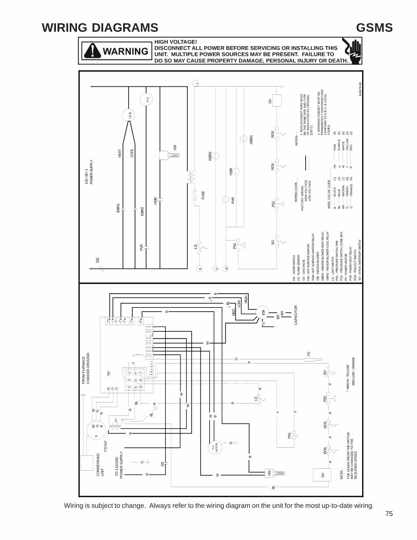
WIRING DIAGRAMSHIGH VOLTAGE!DISCONNECT ALL POWER BEFORE SERVICING OR INSTALLING THISUNIT. MULTIPLE POWER SOURCES MAY BE PRESENT. FAILURE TODO SO MAY CAUSE PROPERTY DAMAGE, PERSONAL INJURY OR DEATH.
Wiring is subject to change. Always refer to the wiring diagram on the unit for the most up-to-date wiring.75
*
12
3
45
6
78
9
*
THE
LEA
DS
FRO
M T
HE
MO
TOR
MAY
BE
CH
ANG
ED T
O T
HE
RE
QU
IRED
SP
EED
.
1. R
EPL
ACEM
ENT
WIR
E M
UST
BE T
HE
SAM
E S
IZE
AND
TYP
EO
F IN
SULA
TIO
N A
S O
RIG
INAL
(105
°C).
2. W
ARN
ING
CA
BIN
ET M
UST
BE
PER
MAN
EN
TLY
GR
OU
ND
ED A
ND
CO
NFO
RM
TO
N.E
.C. &
LO
CA
LC
OD
ES.
POW
ER
SUP
PLY
TO 1
15/1
/60
24V
B
BP.
V.
MO
TOR G
W
G
BRBR
WIR
E C
OLO
R C
OD
E
B BL BR G OO
RA
NG
EG
REE
NB
RO
WN
BLU
EBL
ACK
PIN
KPU
RPL
EW
HIT
EYE
LLO
WR
EDRYWP
K
NO
TE:
P.V.
I.D.B
.
NO
TES:
WIR
ING
CO
DE
FAC
TOR
Y W
IRIN
GH
IGH
VO
LTA
GE
LOW
VO
LTAG
E
B
MED
R
HIG
H
B
LOWBL
BL
115
/ 60
/ 1
HEAT
COO
L
LSC
R G W
PS1
IDB
- IND
OOR
BLO
WER
LS -
LIM
IT S
WIT
CH
DS -
DO
OR
SWIT
CH
PVR
- POW
ER V
ENT
RELA
YRO
S - R
OLLO
UT S
WIT
CH
GV
- GA
S VA
LVE
HSI -
HO
T SU
RFAC
E IG
NITO
R
IDBR
2
IDBR
1 - I
NDOO
R BL
OW
ER H
EAT
RELA
Y
PV -
POW
ER V
ENTO
R
FS -
FLAM
E SE
NSO
R
PS1
LS
DS
IDB
GV
FS
HSI
SO
W
* M
ED H
I - Y
ELLO
W
MED
LOW
- O
RANG
E
COOL
HEAT
M1
M2
HSI
IND
NEU
TRAL
SPR
ITR
ANS
W G R
L2
W
W
R
LIMIT
PSI
PSO
GVFS
LIMIT
Y
R
R
Y
CAP
AC
ITO
R
P
PVR
ROS
GV
IDBR
1
IDBR
2PV
R
HSIR
HOT
SU
RFAC
E IG
NITI
ON
RELA
Y
HSI
FUSE
W G R
B
W
R
O
B
P
FS
TWIN
P
BL
PS1
- PR
ESSU
RE S
WIT
CH, F
IRE
SO -
STAC
K OV
ERTE
MP
SWIT
CH
W RGY
CO
ND
ENS
ING
UN
IT
SO
T'S
TAT
W
G
HSIR
HSIR
POW
ER S
UPPL
Y
P
IDBR
1
BL
ROS
P
FRO
M F
UR
NAC
EC
HAS
SIS
GR
OU
ND
(1)
(4)
(7)
(8)
(6)
(0)
(2)
(3)
(5)
(9)
PS2
- PR
ESSU
RE S
WIT
CH, C
OM
B. B
OX
IDBR
2 - I
NDOO
R BL
OW
ER C
OOL
REL
AY
PS2
PS2
DS
ROS
P
ROS
B28
578-
08
GSMS

76
TWINNING DIAGRAMSHIGH VOLTAGE!DISCONNECT ALL POWER BEFORE SERVICING OR INSTALLING THISUNIT. MULTIPLE POWER SOURCES MAY BE PRESENT. FAILURE TODO SO MAY CAUSE PROPERTY DAMAGE, PERSONAL INJURY OR DEATH.
Wiring is subject to change. Always refer to the wiring diagram on the unit for the most up-to-date wiring.
GSU & GSMTW
INN
ING
DIA
GR
AM
GSU
& G
SMS
TWO
-STA
GE
THER
MO
STAT
NO
TE 1
: MU
ST U
SE O
NE
SOU
RC
E O
F PO
WER
FO
R B
OTH
FU
RN
AC
ES.
ISO
LATI
ON
RE
LAY
ISO
LATI
ON
RE
LAY
RO
OM
TH
ER
MO
STAT
FUR
NA
CE
2FU
RN
AC
E 1
3A ATO
3A ATO
NEUT
RALS
TRNS
SEC
24VA
CCO
M
L1MI
PSO
PSI
L1MO
FS
GV
F1
PSI2
N/U
N/U
N/U
GND
PSO2
GVHI
STAT
US
HI
PRI
TRNS
L2
INDU
CER
LOHSI
MED LOHI
BLOW
ER
M1
24VA
CCO
M
SEC
TRNS
GV
L1MO
L1MI
PSI
PSO
N/U
FS
N/U
N/U
GND
GVHI
PSI2
PSO2
NEUT
RALS
TRNS
PRI
L2
F1
STAT
US
INDU
CER
LOHIHSI
LOMED
BLOW
ERHIM1
W1
W2 G R
TWIN
G RW1
W2
TWIN
W1
W2
RG
Y
BLU
EB
LUE
WH
ITE
BR
OW
NG
REE
NR
ED
CO
ND
EN
SE
RB
LUE
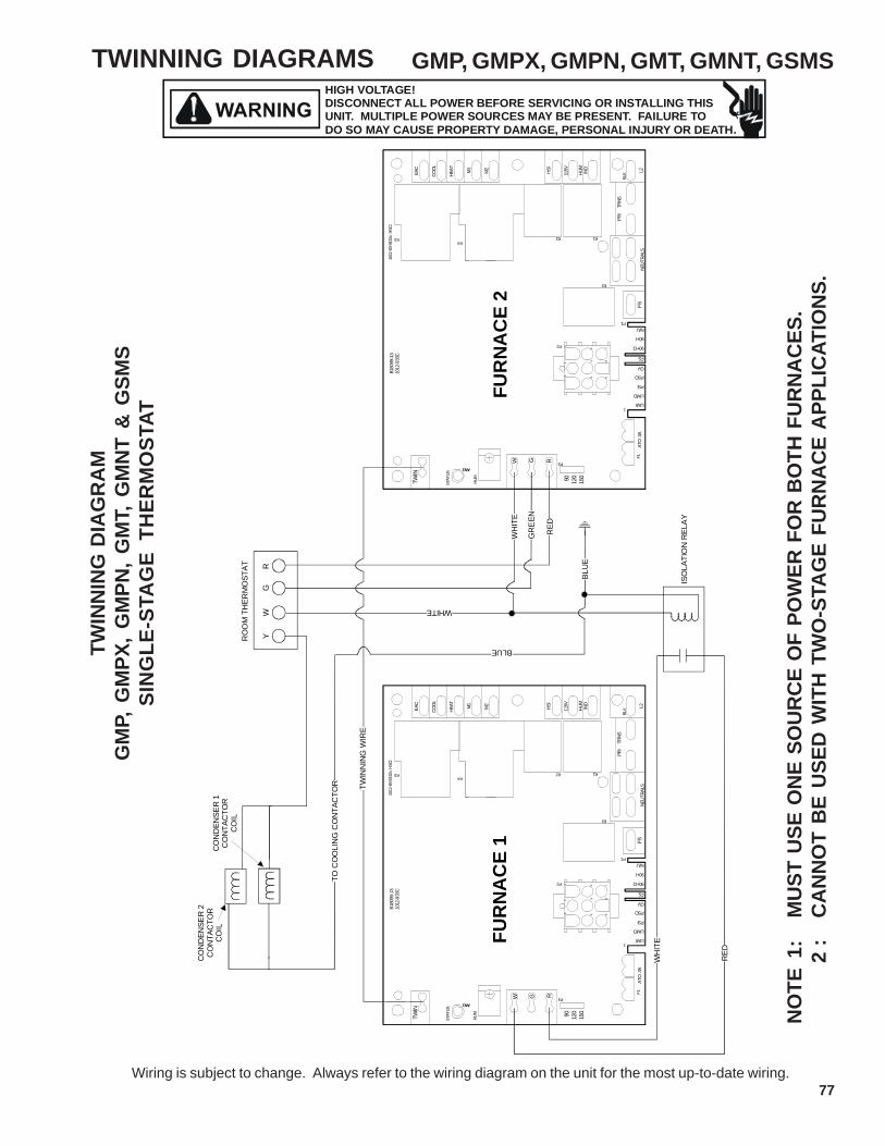
77
TWINNING DIAGRAMS
Wiring is subject to change. Always refer to the wiring diagram on the unit for the most up-to-date wiring.
HIGH VOLTAGE!DISCONNECT ALL POWER BEFORE SERVICING OR INSTALLING THISUNIT. MULTIPLE POWER SOURCES MAY BE PRESENT. FAILURE TODO SO MAY CAUSE PROPERTY DAMAGE, PERSONAL INJURY OR DEATH.
NO
TE 1
:M
UST
USE
ON
E SO
UR
CE
OF
POW
ER F
OR
BO
TH F
UR
NA
CES
.2
:C
AN
NO
T B
E U
SED
WIT
H T
WO
-STA
GE
FUR
NA
CE
APP
LIC
ATIO
NS.
TWIN
NIN
G D
IAG
RA
MG
MP,
GM
PX,
GM
PN,
GM
T, G
MN
T &
GSM
SSI
NG
LE-S
TAG
E TH
ERM
OST
AT
GMP, GMPX, GMPN, GMT, GMNT, GSMS
YW
GR
RO
OM
TH
ERM
OST
AT
WH
ITE
GR
EEN
RED
ISO
LATI
ON
REL
AY
TWIN
NIN
G W
IRE
TRNS
12
3
ATO
3A
LIMI
LIMO
GV
PSI
PSO
FS
150
1
89
56
N/U
90+I
90+O
NEUT
RALS
74
PRI
90 120
BLK
1012
-83-
9332
x H
SCI
B180
99-1
310
12-9
33C
STAT
US
K4
F1FS
K3
P1
K1
P3RGW
AN1
HUM
P2
K2
L2IND
HUM
115VHS
I
M1
M2
TWIN
K5
COOL
HEAT
EAC
FUR
NA
CE
1
TRNS
12
3
ATO
3A
LIMI
LIMO
GV
PSI
PSO
FS
150
1
89
56
N/U
90+I
90+O
NEUT
RALS
74
PRI
90 120
BLK
1012
-83-
9332
x H
SCI
B180
99-1
310
12-9
33C
STAT
US
K4
F1FS
K3
P1
K1
P3RGW
AN1
HUM
P2
K2
L2IND
HUM
115VHS
I
M1
M2
TWIN
K5
COOL
HEAT
EAC
FUR
NA
CE
2
WH
ITE
RED
BLU
E
CO
ND
ENSE
R 1
CO
NTA
CTO
RC
OIL
CO
ND
ENSE
R 2
CO
NTA
CTO
RC
OIL
TO C
OO
LIN
G C
ON
TAC
TOR
BLUE
WHITE