service level definitions implementation agreement...
TRANSCRIPT
Service Level Definitions Implementation Agreement
FRF. 13
Frame Relay Forum Technical CommitteeAugust 4, 1998
Note: The user’s attention is called to the possibility that implementation of the frame relay implementationagreement contained herein may require the use of inventions covered by patent rights held by third parties. Bypublication of this frame relay implementation agreement the Frame Relay Forum makes no representation that theimplementation of the specification will not infringe on any third party rights. The Frame Relay Forum take noposition with respect to any claim that has been or may be asserted by any third party, the validity of any patentrights related to any such claims, or the extent to which a license to use any such rights may not be available.
Editor:
Kenneth RehbehnVisual Networks
For more information contact:
The Frame Relay ForumSuite 30739355 California StreetFremont, CA 94538 USA
Phone: +1 (510) 608-5920FAX: +1 (510) 608-5917E-Mail: [email protected]: http://www.frforum.com
Copyright © Frame Relay Forum 1998. All Rights Reserved.
This document and translations of it may be copied and furnished to others, and works thatcomment on or otherwise explain it or assist in its implementation may be prepared, copied,published and distributed, in whole or in part, without restriction of any kind, provided that theabove copyright notice and this paragraph are included on all such copies and derivative works.However, this document itself may not be modified in any way, such as by removing the copyrightnotice or references to the Frame Relay Forum, except as needed for the purpose of developingFrame Relay standards (in which case the procedures for copyrights defined by the Frame RelayForum must be followed), or as required to translate it into languages other than English.
This document and the information contained herein is provided on an "AS IS" basis and THEFRAME RELAY FORUM DISCLAIMS ALL WARRANTIES, EXPRESS OR IMPLIED,INCLUDING BUT NOT LIMITED TO ANY WARRANTY THAT THE USE OF THEINFORMATION HEREIN WILL NOT INFRINGE ANY RIGHTS OR ANY IMPLIEDWARRANTIES OF MERCHANTABILITY OR FITNESS FOR A PARTICULAR PURPOSE.
Service Level Definitions Implementation Agreement FRF.13
August 4, 1998 Page i
Table of Contents
1 INTRODUCTION .................................................................................................................................. 1
1.1 PURPOSE........................................................................................................................................... 11.2 DEFINITIONS..................................................................................................................................... 21.3 TERMINOLOGY.................................................................................................................................. 21.4 ACRONYM LIST................................................................................................................................. 21.5 RELEVANT STANDARDS..................................................................................................................... 3
2 REFERENCE MODEL ......................................................................................................................... 4
2.1 CONNECTION COMPONENTS.............................................................................................................. 42.2 FRAME TRANSFER REFERENCE EVENTS............................................................................................. 52.3 CONNECTION PATH REFERENCE POINTS............................................................................................. 52.4 SERVICE LEVEL DEFINITION MEASUREMENT DOMAIN ........................................................................ 7
2.4.1 Edge-to-Edge Interface ............................................................................................................. 72.4.2 Edge-to-Edge Egress Queue...................................................................................................... 82.4.3 End-to-End............................................................................................................................... 8
3 DELAY................................................................................................................................................... 9
3.1 PARAMETER DEFINITION ................................................................................................................... 93.2 MEASUREMENT METHODOLOGY........................................................................................................ 93.3 MEASUREMENT AGGREGATION....................................................................................................... 10
4 FRAME DELIVERY RATIO.............................................................................................................. 11
4.1 PARAMETER DEFINITION ................................................................................................................. 114.2 MEASUREMENT METHODOLOGY...................................................................................................... 114.3 MEASUREMENT AGGREGATION....................................................................................................... 13
5 DATA DELIVERY RATIO................................................................................................................. 14
5.1 PARAMETER DEFINITION ................................................................................................................. 145.2 MEASUREMENT METHODOLOGY...................................................................................................... 145.3 MEASUREMENT AGGREGATION....................................................................................................... 15
6 SERVICE AVAILABILITY ................................................................................................................ 16
6.1 PARAMETER DEFINITION ................................................................................................................. 166.2 MEASUREMENT METHODOLOGY...................................................................................................... 176.3 MEASUREMENT AGGREGATION....................................................................................................... 18
A INFORMATIVE ANNEX - SOURCES OF EGRESS QUEUE CONGESTION ............................... 19
A.1 COMMITTED TRAFFIC OVERSUBSCRIPTION....................................................................................... 19A.2 EXCESS TRAFFIC OVERSUBSCRIPTION.............................................................................................. 20
B INFORMATIVE ANNEX - EXAMPLES OF SERVICE LEVEL PARAMETER AGGREGATION21
B.1 DELAY............................................................................................................................................ 21B.2 FRAME DELIVERY RATIO ................................................................................................................ 21B.3 DATA DELIVERY RATIO .................................................................................................................. 21B.4 SERVICE AVAILABILITY .................................................................................................................. 21
FRF.13 Service Level Definitions Implementation Agreement
Page ii August 4, 1998
List of TablesTable 1 Locations for delay measurement ...............................................................................................................9Table 2 Classification of failures...........................................................................................................................17
List of FiguresFigure 1 Single public network ...............................................................................................................................4Figure 2 Connection over two public networks........................................................................................................5Figure 3 Connection via intermediate transit network ..............................................................................................5Figure 4 Reference points for calculation of service level definitions.......................................................................6Figure 5 Service level definition reference model ....................................................................................................8Figure 6 Frame delivery adjustments.....................................................................................................................12Figure 7 Oversubscription with multiple connections ............................................................................................19Figure 8 Mismatched interface speeds...................................................................................................................20
Service Level Definitions Implementation Agreement FRF.13
August 4, 1998 Page iii
Revision History
Version Change DateFRF.13 Document Approved August 4, 1998

FRF.13 Service Level Definitions Implementation Agreement
Page iv August 4, 1998
This Page Left Blank Intentionally
Service Level Definitions Implementation Agreement FRF.13
August 4, 1998 Page 1
1 Introduction
1.1 PurposeFrame relay service offerings are available from a wide variety of network service providers. Each providerdescribes the offering by specifying user information transfer parameters. End-users of frame relay services utilizethese parameters to:
• Compare different frame relay network service providers,
• Measure the quality of specific frame relay service offerings, and
• Enforce contractual commitments.
Network service providers and equipment vendors also utilize these parameters to plan, describe, and evaluate framerelay products and service offerings.
This document establishes a Frame Relay Forum Implementation Agreement on the definitions of transferparameters that describe frame relay service performance. These parameters are suitable for reference by networkService Level Agreement (SLA) documents established between the network service provider and the customer.They also are suitable for reference by SLA documents established between network service providers. Theseparameters may be applied to the information transfer phase of PVC or SVC implementations and services.
The definitions of these parameters reflect common industry practice. Where appropriate, the principles documentedin ITU Recommendation X.144, User Information Transfer Performance Parameters for Data Networks ProvidingInternational Frame Relay PVC Service, are applied. The frame relay service is described in [2], [3], [4], [5], [6],[7], [8] and [9].
The parameters address the following characteristics of frame relay service:
• Frame transfer delay,
• Frame delivery ratio,
• Data delivery ratio, and
• Service availability.
The focus of this agreement is the definition of these parameters. An implementation or service may claimcompliance to this agreement when the following conditions are met:
a) Whenever any of the parameters identified in Section 1.3 are referenced, they are used as defined withinthis agreement, and
b) Whenever any of the parameters identified in Section 1.3 are referenced, all applicable requirements ofthe appropriate section of this agreement are met.
This IA is organized as follows:
• Section 2 defines a reference model that provides a basis for performance parameter definition.
• Section 3 defines VC frame-based delay parameters,
• Section 4 defines VC frame-based delivery ratio parameters,
• Section 5 defines VC data delivery ratio parameters,
• Section 6 defines VC service availability parameters, and
• Appendix A and Appendix B to provide additional information.
FRF.13 Service Level Definitions Implementation Agreement
Page 2 August 4, 1998
1.2 DefinitionsMust, Shall, or Mandatory — the item is an absolute requirement of the implementation agreement.
Should — the item is highly desirable.
May or Optional — the item is not compulsory and may be followed or ignored according to the needs of theimplementor.
1.3 TerminologyFrame Transfer Delay (FTD) — Refer to Section 3 for definition.
Frame Delivery Ratio (FDR, FDRc, FDRe) — Refer to Section 4 for definition.
Data Delivery Ratio (DDR, DDRc, DDRe) — Refer to Section 5 for definition.
Service Availability (FRVCA, FRMTTR, FRMTBSO) — Refer to Section 6 for definition.
1.4 Acronym ListACS Access Circuit Section
ANS Access Network Section
Be Excess Burst
CIR Committed Information Rate
CPE Customer Premises Equipment
DDR Data Delivery Ratio
DesRP Destination Reference Point
DLCI Data Link Connection Identifier
DTE Data Terminal Equipment
EqiRP Egress Queue Input Reference Point
EqoRP Egress Queue Output Reference Point
FCS Frame Check Sequence
FDR Frame Delivery Ratio
FO Fault Outage
FRMTBSO Frame Relay Mean Time Between Service Outages
FRMTTR Frame Relay Mean Time to Repair
FRVCA Frame Relay Virtual Connection Availability
FTD Frame Transfer Delay
IA Implementation Agreement
ICS Internetwork Circuit Section
IngRP Ingress Reference Point
L1 Layer 1 – Physical Layer of OSI Reference Model

Service Level Definitions Implementation Agreement FRF.13
August 4, 1998 Page 3
L2 Layer 2 – Link Layer of OSI Reference Model
kbps kilobits per second
Mbps Megabits per second
OA&M Operations, Administration, and Maintenance
PVC Permanent Virtual Connection
SLA Service Level Agreement
SrcRP Source Reference Point
SVC Switched Virtual Connection
TNS Transit Network Section
TpRP Traffic Policing Reference Point
UNI User Network Interface
VC Virtual Connection
1.5 Relevant StandardsThe following is a list of standards on which these implementation agreements are based:
[1] X.144 ITU-T. Recommendation X.144 (1995), User information transfer performanceparameters for data networks providing international frame relay PVC service.
[2] I.122 ITU-T. Recommendation I.122 (1988), Framework for providing additional packet modebearer services.
[3] I.233 ITU-T. Recommendation I.233 (1991), Frame mode bearer services.
[4] I.233.1 ITU-T. Recommendation I.233.1 (1991), ISDN frame relaying bearer service.
[5] I.370 ITU-T. Recommendation I.370 (1991), Congestion management for the ISDN framerelaying bearer service.
[6] X.36 ITU-T. Recommendation X.36 (1994), Interface between Data Terminal Equipment(DTE) and Data circuit-terminating Equipment for public data networks providing framerelay data transmission service by dedicated circuit.
[7] X.76 ITU-T. Recommendation X.76 (1995), Network-to-network interface between public datanetworks providing the frame relay data transmission service.
[8] Q.922 ITU-T. Recommendation Q.922, ISDN Data Link Layer Specification for Frame ModeBearer Services.
[9] Q.933 ITU-T. Recommendation Q.933, ISDN Signaling Specification for Frame Mode BearerServices.
[10] NMF 701 Network Management Forum. Performance Reporting Definitions Document, Issue 1.0,April 1997.
FRF.13 Service Level Definitions Implementation Agreement
Page 4 August 4, 1998
2 Reference ModelThis agreement addresses user information transfer performance parameters that apply to a point-to-point framerelay connection (i.e., a VC – either a PVC or the data transfer part of a SVC) section or a concatenated set ofconnection sections.
2.1 Connection ComponentsSection 4 of X.144 defines the basic component types of an end-to-end connection. These connection section typesare:
• The Access Circuit Section (ACS),
• The Internetwork Circuit Section (ICS),
• The Access Network Section (ANS), and
• The Transit Network Section (TNS).
These sections provide building blocks for representing the structure of any end-to-end connection. This agreementapplies to the uni-directional transfer of user information on either a single section or a series of concatenatedsections.
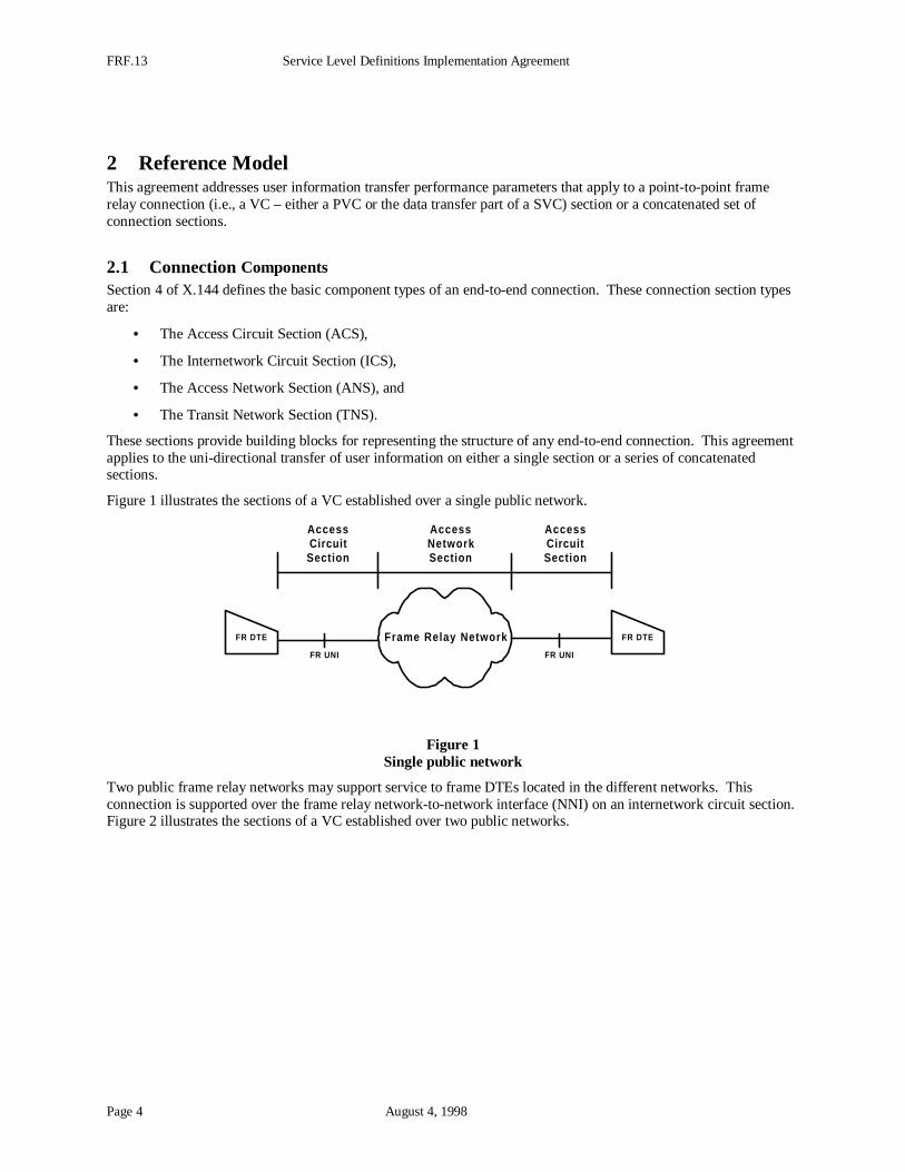
Figure 1 illustrates the sections of a VC established over a single public network.
Frame Relay Network
AccessCircuitSection
FR DTE
FR UNI
FR DTE
FR UNI
AccessNetworkSection
AccessCircuitSection
Figure 1Single public network
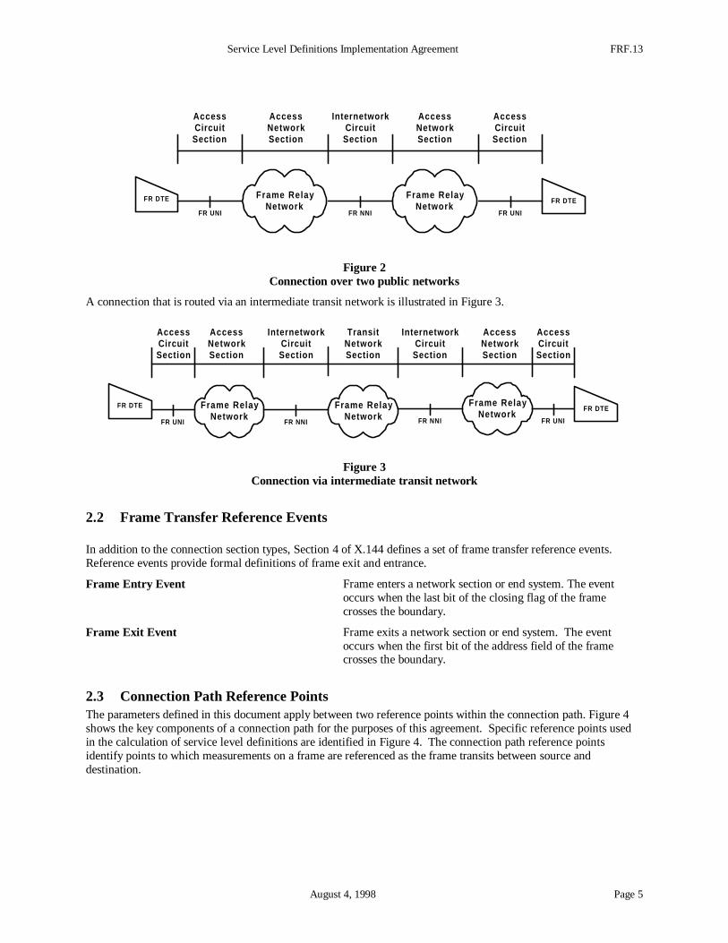
Two public frame relay networks may support service to frame DTEs located in the different networks. Thisconnection is supported over the frame relay network-to-network interface (NNI) on an internetwork circuit section.Figure 2 illustrates the sections of a VC established over two public networks.
Service Level Definitions Implementation Agreement FRF.13
August 4, 1998 Page 5
Frame RelayNetwork
FR DTEFR DTE
FR UNI FR NNI
Frame RelayNetwork
FR UNI
AccessCircuitSection
AccessNetworkSection
AccessNetworkSection
AccessCircuitSection
InternetworkCircuitSection
Figure 2Connection over two public networks
A connection that is routed via an intermediate transit network is illustrated in Figure 3.
Frame RelayNetwork
FR UNI
FR DTE Frame RelayNetwork
Frame RelayNetwork
FR UNI
FR DTE
FR NNI FR NNI
AccessCircuitSection
AccessNetworkSection
AccessCircuitSection
InternetworkCircuitSection
InternetworkCircuitSection
TransitNetworkSection
AccessNetworkSection
Figure 3Connection via intermediate transit network
2.2 Frame Transfer Reference Events
In addition to the connection section types, Section 4 of X.144 defines a set of frame transfer reference events.Reference events provide formal definitions of frame exit and entrance.
Frame Entry Event Frame enters a network section or end system. The eventoccurs when the last bit of the closing flag of the framecrosses the boundary.
Frame Exit Event Frame exits a network section or end system. The eventoccurs when the first bit of the address field of the framecrosses the boundary.
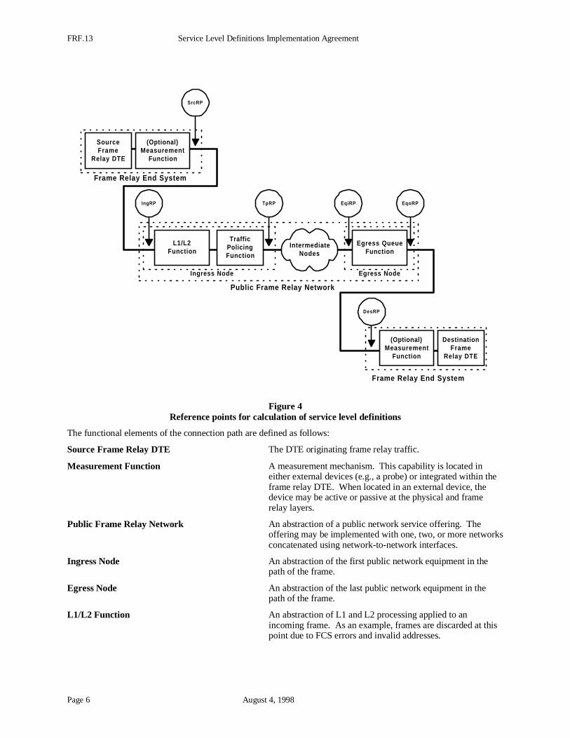
2.3 Connection Path Reference PointsThe parameters defined in this document apply between two reference points within the connection path. Figure 4shows the key components of a connection path for the purposes of this agreement. Specific reference points usedin the calculation of service level definitions are identified in Figure 4. The connection path reference pointsidentify points to which measurements on a frame are referenced as the frame transits between source anddestination.
FRF.13 Service Level Definitions Implementation Agreement
Page 6 August 4, 1998
Frame Relay End System
Frame Relay End System
Ingress Node Egress Node
Public Frame Relay Network
Egress QueueFunction
IntermediateNodes
L1/L2Function
TrafficPolicingFunction
SourceFrame
Relay DTE
(Optional)Measurement
Function
TpRP
SrcRP
EqiRP EqoRP
DesRP
IngRP
DestinationFrame
Relay DTE
(Optional)Measurement
Function
Figure 4Reference points for calculation of service level definitions
The functional elements of the connection path are defined as follows:
Source Frame Relay DTE The DTE originating frame relay traffic.
Measurement Function A measurement mechanism. This capability is located ineither external devices (e.g., a probe) or integrated within theframe relay DTE. When located in an external device, thedevice may be active or passive at the physical and framerelay layers.
Public Frame Relay Network An abstraction of a public network service offering. Theoffering may be implemented with one, two, or more networksconcatenated using network-to-network interfaces.
Ingress Node An abstraction of the first public network equipment in thepath of the frame.
Egress Node An abstraction of the last public network equipment in thepath of the frame.
L1/L2 Function An abstraction of L1 and L2 processing applied to anincoming frame. As an example, frames are discarded at thispoint due to FCS errors and invalid addresses.
Service Level Definitions Implementation Agreement FRF.13
August 4, 1998 Page 7
Traffic Policing Function An abstraction of traffic policing functions applied to anincoming frame. As an example, some network equipmentdiscards frames at this point when traffic exceeds burst excesslimitations of the connection.
Egress Queue Function An abstraction of a physical interface transmission queue. Allframes for all connections are queued here. Someimplementations support an aggregation of connection CIRcommitments in excess of the bandwidth available on aninterface (refer to Annex A for additional information). Insuch implementations, frames may be discarded by the egressqueue function when queue growth exceeds the system'sresources.
Destination Frame Relay DTE The DTE receiving frames.
The reference points of the connection path are defined as follows:
Source Reference Point (SrcRP) Measurement point at source end system.
Ingress Reference Point (IngRP) Measurement point at the ingress to the ingress node
Destination Reference Point (DesRP) Measurement point at destination end system.
Traffic Policing Reference Point (TpRP) Measurement point after L1/L2 and traffic policing functionshave processed a frame.
Egress Queue Input Reference Point (EqiRP) Measurement point prior to interface transmission queue.
Egress Queue Output Reference Point (EqoRP) Measurement point after interface transmission queue.
2.4 Service Level Definition Measurement DomainService level definitions apply to connection sections as described in the applicable service level agreement. Thescope of coverage can include the following measurement domains:
• Edge-to-Edge Interface
• Edge-to-Edge Egress Queue
• End-to-End
The characteristics of measurement domain are described in the following sections.
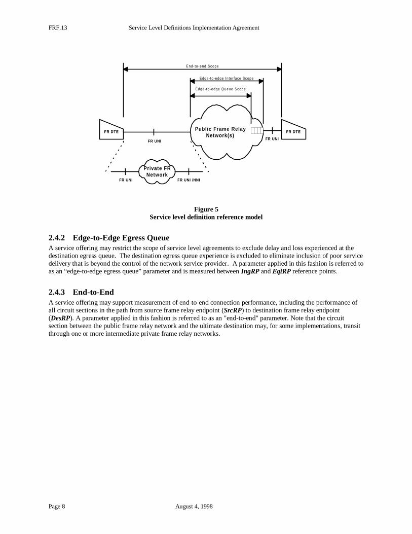
2.4.1 Edge-to-Edge InterfaceA service offering may restrict measurement to connection sections for which the carrier has direct control. Thus,the parameter applies from one edge of a frame relay network cloud to the other edge as shown in Figure 5. Aparameter applied in this fashion is referred to as an "edge-to-edge" interface parameter and is measured betweenIngRP and EqoRP reference points.
FRF.13 Service Level Definitions Implementation Agreement
Page 8 August 4, 1998
FR DTE
FR UNI FR UNI
Publ ic Frame RelayNetwork(s)
FR DTE
Private FRNetwork
FR UNI FR UNI /NNI
End- to -end Scope
Edge- to -edge Queue Scope
Edge- to -edge In te r face Scope
Figure 5Service level definition reference model
2.4.2 Edge-to-Edge Egress QueueA service offering may restrict the scope of service level agreements to exclude delay and loss experienced at thedestination egress queue. The destination egress queue experience is excluded to eliminate inclusion of poor servicedelivery that is beyond the control of the network service provider. A parameter applied in this fashion is referred toas an “edge-to-edge egress queue” parameter and is measured between IngRP and EqiRP reference points.
2.4.3 End-to-EndA service offering may support measurement of end-to-end connection performance, including the performance ofall circuit sections in the path from source frame relay endpoint (SrcRP) to destination frame relay endpoint(DesRP). A parameter applied in this fashion is referred to as an "end-to-end" parameter. Note that the circuitsection between the public frame relay network and the ultimate destination may, for some implementations, transitthrough one or more intermediate private frame relay networks.
Service Level Definitions Implementation Agreement FRF.13
August 4, 1998 Page 9
3 Delay
3.1 Parameter DefinitionFrame Transfer Delay parameters report the time required to transport frame relay data through the network. Theframe transfer delay service level parameter is the difference in milliseconds between the time a frame exits a sourceand the time the same frame enters the destination. The formal definition of frame transfer delay is as follows:
12 ttFTD −=
Where:
t1 is the time in milliseconds when a frame left the source (i.e., frame exit event), and
t2 is the time in milliseconds when a frame arrived at the destination (i.e., frame entryevent.
The source and destination locations where delay measurements are made must be specified as part of a service levelagreement. Delay measurements may be structured to produce end-to-end, edge-to-edge interface, or edge-to-edgeegress queue parameters. For the edge-to-edge egress queue measurement domain the destination arrival time isrecorded when the frame arrives at the egress queue function servicing the destination interface.
Table 1 identifies the applicable reference points of Figure 4 for each type of delay measurement.
Measurement Domain Source Destination
End-to-end SrcRP DesRP
Edge-to-edge Interface IngRP EqoRP
Edge-to-edge Egress Queue IngRP EqiRP
Table 1Locations for delay measurement
Delay jitter parameters are not addressed in this agreement. Support for delay jitter service level parametersincluding the associated measurement and aggregation methodologies are for further study.
3.2 Measurement MethodologyThe mechanism used to perform the measurement of delay is not specified in this agreement. Definition of a framerelay OA&M mechanism that tracks delay is for further study. Mechanisms that depend on a round-trip delaymeasurement may derive the one-way measurement by dividing a round-trip delay measurement by two.
Delay must be measured using consistent frame sizes. Delay measurements are made using a default 128 octetreference frame (payload without address field or FCS), unless otherwise specified in the service level agreement.
Service level agreements must describe the following:
• measurement domain,
• applicable reference points,
• delay measurement mechanism,
• identification of connections subject to measurement,
• measurement frequency, and
• frame size.
FRF.13 Service Level Definitions Implementation Agreement
Page 10 August 4, 1998
Specification of the delay measurement mechanism may address issues such as:
• the use of specially generated delay measurement frames or the use of customer originated frames and
• the use of special connections dedicated to service level monitoring.
3.3 Measurement AggregationService level agreements may aggregate delay measurements. Aggregation may include components such asfrequency of delay measurement, the number of connections aggregated, and the time period reported. Section B.1provides example delay aggregation mechanisms.
The methodology applied by a service level agreement to aggregate delay measurements is outside the scope of thisagreement.
Service level agreements using aggregation must describe the measurement aggregation methodology. Thesedescriptions must specify how aggregation is processed over the following:
• the object dimension (e.g., on a per VC basis, on an interface basis, on a per customer network basis, etc.),and
• the time dimension (e.g., day, week, month, 24-hour day versus business day, 7-day weeks versus businessday weeks, etc.).
Service Level Definitions Implementation Agreement FRF.13
August 4, 1998 Page 11
4 Frame Delivery Ratio
4.1 Parameter DefinitionThe Frame Delivery Ratio (FDR) service level parameter reports the network's effectiveness in transporting anoffered frame relay load in one direction of a single virtual connection. The FDR is a ratio of successful framereceptions to attempted frame transmissions. Attempted frame transmissions are referred to as Frames Offered.Successfully delivered frames are referred to as Frames Delivered. These loads may be further differentiated asbeing within the committed information rate or as burst excess.
Three frame relay ratios may be reported:
FDR Frame Delivery Ratio:
( )( ) ec
ec
ec
ec
redFramesOffe
veredFramesDeli
redFramesOfferedFramesOffe
veredFramesDeliveredFramesDeliFDR
+
+=
++=
FDRc Frame Delivery Ratio for load consisting of frames within the committed information rate:
c
cc
redFramesOffe
veredFramesDeliFDR =
FDRe Frame Delivery Ratio for load in excess of the committed information rate:
e
ee
redFramesOffe
veredFramesDeliFD =R
Where,
FramesDeliveredc Successfully delivered frames within committed information rate,
FramesDeliverede Successfully delivered frames in excess of CIR,
FramesDeliveredc+e Successfully delivered total frames, including those within committedinformation rate and those in excess of CIR,
FramesOfferedc Attempted frame transmissions within committed information rate,
FramesOfferede Attempted frame transmissions in excess of CIR, and
FramesOfferedc+e Attempted total frame transmissions, including those within committedinformation rate and those in excess of CIR.
An independent set of frame delivery ratios exists for each direction of a full duplex connection.
4.2 Measurement MethodologyThe mechanism used to perform the measurement of frame delivery ratio is not specified in this agreement.However, the quantities FramesDelivered and FramesOffered identified in Section 4.1 are associated with aspecified measurement interval and should correspond to the same set of frames. Thus, the received frames countedby FramesDelivered correspond to the sent frames counted by FramesOffered. The Frame Relay Forum isstudying the definition of a frame relay delivery measurement mechanism using Operations, Administration, andMaintenance (OA&M) frames.
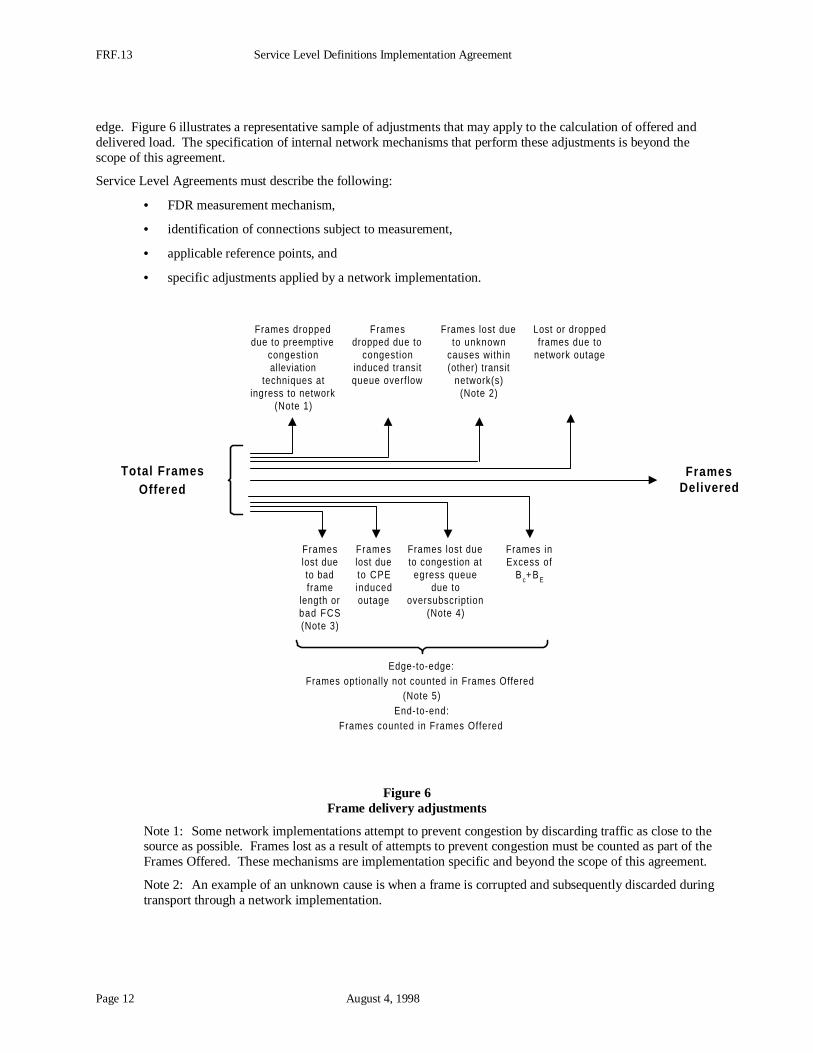
Network implementations may adjust the Frames Offered parameter to eliminate frames from a delivery ratiocalculation. Adjustments may be applied depending on the type of service level agreement: end-to-end or edge-to-
FRF.13 Service Level Definitions Implementation Agreement
Page 12 August 4, 1998
edge. Figure 6 illustrates a representative sample of adjustments that may apply to the calculation of offered anddelivered load. The specification of internal network mechanisms that perform these adjustments is beyond thescope of this agreement.
Service Level Agreements must describe the following:
• FDR measurement mechanism,
• identification of connections subject to measurement,
• applicable reference points, and
• specific adjustments applied by a network implementation.
Frameslost dueto badframe
length orbad FCS(Note 3)
Frameslost dueto CPEinducedoutage
Frames lost dueto congestion at
egress queuedue to
oversubscription(Note 4)
Edge-to-edge:Frames optionally not counted in Frames Offered
(Note 5)End-to-end:
Frames counted in Frames Offered
Frames droppeddue to preemptive
congestionalleviation
techniques atingress to network
(Note 1)
Framesdropped due to
congestioninduced transitqueue overflow
Frames lost dueto unknown
causes within(other) transit
network(s)(Note 2)
Lost or droppedframes due to
network outage
Frames inExcess of
B c+ BE
FramesDelivered
Total FramesOffered
Figure 6Frame delivery adjustments
Note 1: Some network implementations attempt to prevent congestion by discarding traffic as close to thesource as possible. Frames lost as a result of attempts to prevent congestion must be counted as part of theFrames Offered. These mechanisms are implementation specific and beyond the scope of this agreement.
Note 2: An example of an unknown cause is when a frame is corrupted and subsequently discarded duringtransport through a network implementation.
Service Level Definitions Implementation Agreement FRF.13
August 4, 1998 Page 13
Note 3: This adjustment is applied to invalid frames received from the customer equipment at IngRP.Invalid frames cannot be attributed to the Frames Offered for a specific DLCI. Implementations must trackthis loss by incrementing loss counters associated with the interface rather than a virtual connection.
Note 4: Some network implementations may have the ability to track frame loss due to customer over-subscription1 of the egress interface. For example, if an egress interface is over-subscribed and queuegrowth occurs at the egress queue, frames might be discarded at EqiRP or some earlier reference point.These mechanisms are implementation specific and beyond the scope of this agreement.
Note 5: Edge-to-edge service level agreements may include these statistics.
4.3 Measurement AggregationService level agreements aggregate frame delivery ratio measurements. Aggregation may have components thatinclude the number of connections aggregated and the time period reported. Section B.2 provides example framedelivery ratio aggregation mechanisms.
The methodology applied by a service level agreement to aggregate frame delivery ratios is outside the scope of thisagreement.
Service level agreements using aggregation must define the measurement aggregation methodology. Thesedescriptions must specify how aggregation is processed over the following:
• the object dimension (e.g., on a per VC basis, on an interface basis, on a per customer network basis, etc.),and
• the time dimension (e.g., day, week, month, 24-hour day versus business day, 7-day weeks versus businessday weeks, etc.).
1 See Section A
FRF.13 Service Level Definitions Implementation Agreement
Page 14 August 4, 1998
5 Data Delivery Ratio
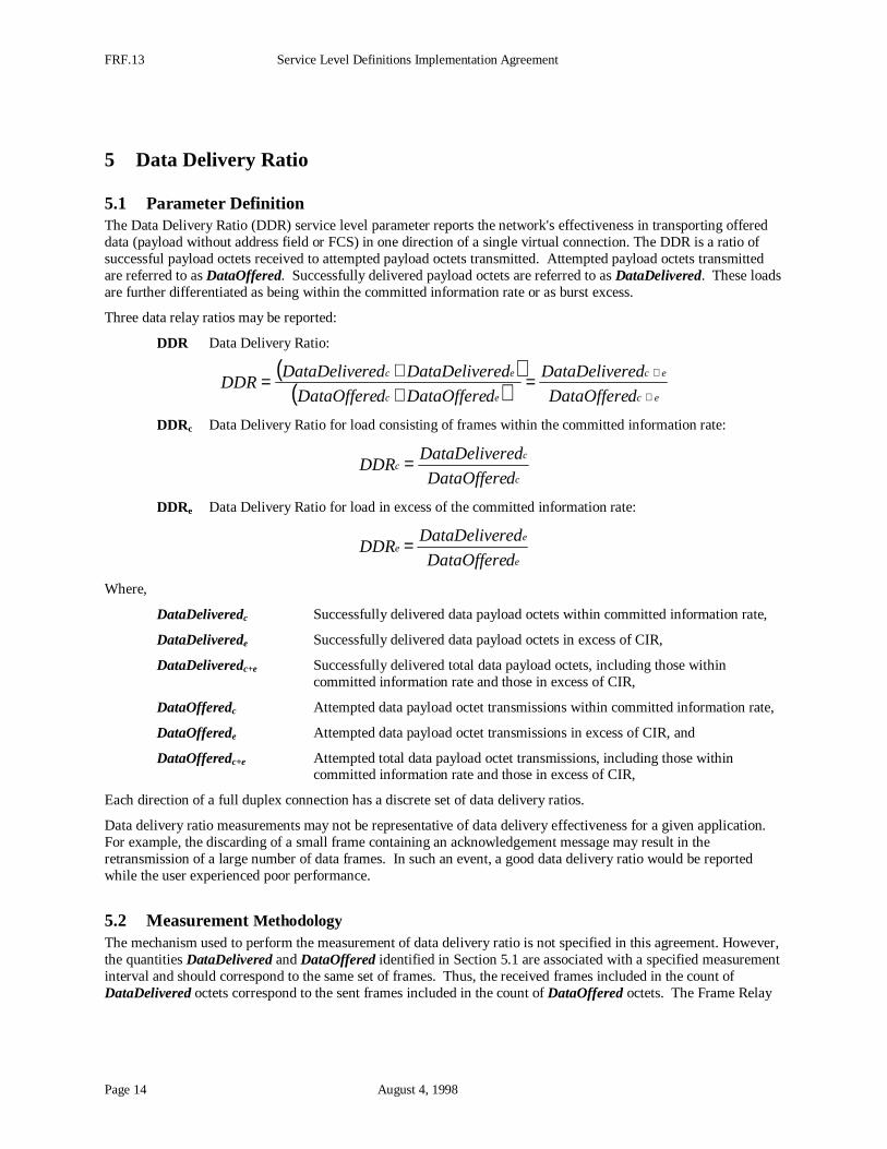
5.1 Parameter DefinitionThe Data Delivery Ratio (DDR) service level parameter reports the network's effectiveness in transporting offereddata (payload without address field or FCS) in one direction of a single virtual connection. The DDR is a ratio ofsuccessful payload octets received to attempted payload octets transmitted. Attempted payload octets transmittedare referred to as DataOffered. Successfully delivered payload octets are referred to as DataDelivered. These loadsare further differentiated as being within the committed information rate or as burst excess.
Three data relay ratios may be reported:
DDR Data Delivery Ratio:
( )( ) ec
ec
ec
ec
dDataOffere
redDataDelive
dDataOfferedDataOffere
redDataDeliveredDataDeliveDDR
+
+=
++=
DDRc Data Delivery Ratio for load consisting of frames within the committed information rate:
c
cc
dDataOffere
redDataDeliveDDR =
DDRe Data Delivery Ratio for load in excess of the committed information rate:
e
ee
dDataOffere
redDataDeliveDDR =
Where,
DataDeliveredc Successfully delivered data payload octets within committed information rate,
DataDeliverede Successfully delivered data payload octets in excess of CIR,
DataDeliveredc+e Successfully delivered total data payload octets, including those withincommitted information rate and those in excess of CIR,
DataOfferedc Attempted data payload octet transmissions within committed information rate,
DataOfferede Attempted data payload octet transmissions in excess of CIR, and
DataOfferedc+e Attempted total data payload octet transmissions, including those withincommitted information rate and those in excess of CIR,
Each direction of a full duplex connection has a discrete set of data delivery ratios.
Data delivery ratio measurements may not be representative of data delivery effectiveness for a given application.For example, the discarding of a small frame containing an acknowledgement message may result in theretransmission of a large number of data frames. In such an event, a good data delivery ratio would be reportedwhile the user experienced poor performance.
5.2 Measurement MethodologyThe mechanism used to perform the measurement of data delivery ratio is not specified in this agreement. However,the quantities DataDelivered and DataOffered identified in Section 5.1 are associated with a specified measurementinterval and should correspond to the same set of frames. Thus, the received frames included in the count ofDataDelivered octets correspond to the sent frames included in the count of DataOffered octets. The Frame Relay
Service Level Definitions Implementation Agreement FRF.13
August 4, 1998 Page 15
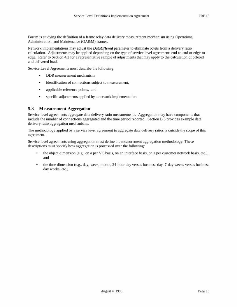
Forum is studying the definition of a frame relay data delivery measurement mechanism using Operations,Administration, and Maintenance (OA&M) frames.
Network implementations may adjust the DataOffered parameter to eliminate octets from a delivery ratiocalculation. Adjustments may be applied depending on the type of service level agreement: end-to-end or edge-to-edge. Refer to Section 4.2 for a representative sample of adjustments that may apply to the calculation of offeredand delivered load.
Service Level Agreements must describe the following:
• DDR measurement mechanism,
• identification of connections subject to measurement,
• applicable reference points, and
• specific adjustments applied by a network implementation.
5.3 Measurement AggregationService level agreements aggregate data delivery ratio measurements. Aggregation may have components thatinclude the number of connections aggregated and the time period reported. Section B.3 provides example datadelivery ratio aggregation mechanisms.
The methodology applied by a service level agreement to aggregate data delivery ratios is outside the scope of thisagreement.
Service level agreements using aggregation must define the measurement aggregation methodology. Thesedescriptions must specify how aggregation is processed over the following:
• the object dimension (e.g., on a per VC basis, on an interface basis, on a per customer network basis, etc.),and
• the time dimension (e.g., day, week, month, 24-hour day versus business day, 7-day weeks versus businessday weeks, etc.).
FRF.13 Service Level Definitions Implementation Agreement
Page 16 August 4, 1998
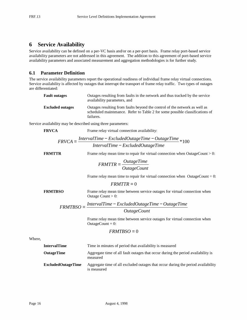
6 Service AvailabilityService availability can be defined on a per-VC basis and/or on a per-port basis. Frame relay port-based serviceavailability parameters are not addressed in this agreement. The addition to this agreement of port-based serviceavailability parameters and associated measurement and aggregation methodologies is for further study.
6.1 Parameter DefinitionThe service availability parameters report the operational readiness of individual frame relay virtual connections.Service availability is affected by outages that interrupt the transport of frame relay traffic. Two types of outagesare differentiated:
Fault outages Outages resulting from faults in the network and thus tracked by the serviceavailability parameters, and
Excluded outages Outages resulting from faults beyond the control of the network as well asscheduled maintenance. Refer to Table 2 for some possible classifications offailures.
Service availability may be described using three parameters:
FRVCA Frame relay virtual connection availability:
100*tageTimeExcludedOumeIntervalTi
OutageTimetageTimeExcludedOumeIntervalTiFRVCA
−−−=
FRMTTR Frame relay mean time to repair for virtual connection when OutageCount > 0:
tOutageCoun
OutageTimeFRMTTR=
Frame relay mean time to repair for virtual connection when OutageCount = 0:
0=FRMTTR
FRMTBSO Frame relay mean time between service outages for virtual connection whenOutage Count > 0:
tOutageCoun
OutageTimetageTimeExcludedOumeIntervalTiFRMTBSO
−−=
Frame relay mean time between service outages for virtual connection whenOutageCount = 0:
0=FRMTBSO
Where,
IntervalTime Time in minutes of period that availability is measured
OutageTime Aggregate time of all fault outages that occur during the period availability ismeasured
ExcludedOutageTime Aggregate time of all excluded outages that occur during the period availabilityis measured
Service Level Definitions Implementation Agreement FRF.13
August 4, 1998 Page 17
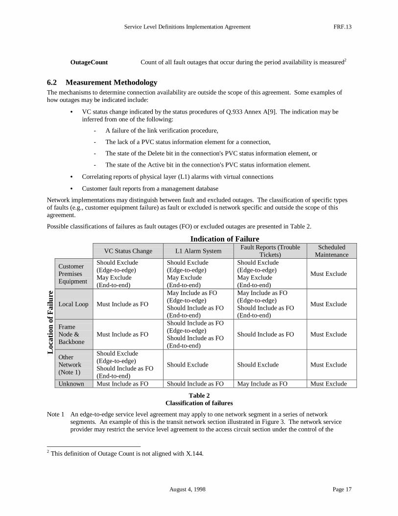
OutageCount Count of all fault outages that occur during the period availability is measured2
6.2 Measurement MethodologyThe mechanisms to determine connection availability are outside the scope of this agreement. Some examples ofhow outages may be indicated include:
• VC status change indicated by the status procedures of Q.933 Annex A[9]. The indication may beinferred from one of the following:
- A failure of the link verification procedure,
- The lack of a PVC status information element for a connection,
- The state of the Delete bit in the connection's PVC status information element, or
- The state of the Active bit in the connection's PVC status information element.
• Correlating reports of physical layer (L1) alarms with virtual connections
• Customer fault reports from a management database
Network implementations may distinguish between fault and excluded outages. The classification of specific typesof faults (e.g., customer equipment failure) as fault or excluded is network specific and outside the scope of thisagreement.
Possible classifications of failures as fault outages (FO) or excluded outages are presented in Table 2.
Indication of Failure
VC Status Change L1 Alarm SystemFault Reports (Trouble
Tickets)Scheduled
Maintenance
CustomerPremisesEquipment
Should Exclude(Edge-to-edge)May Exclude(End-to-end)
Should Exclude(Edge-to-edge)May Exclude(End-to-end)
Should Exclude(Edge-to-edge)May Exclude(End-to-end)
Must Exclude
Local Loop Must Include as FO
May Include as FO(Edge-to-edge)Should Include as FO(End-to-end)
May Include as FO(Edge-to-edge)Should Include as FO(End-to-end)
Must Exclude
FrameNode &Backbone
Must Include as FO
Should Include as FO(Edge-to-edge)Should Include as FO(End-to-end)
Should Include as FO Must Exclude
OtherNetwork(Note 1)
Should Exclude(Edge-to-edge)Should Include as FO(End-to-end)
Should Exclude Should Exclude Must Exclude
Loca
tion
of F
ailu
re
Unknown Must Include as FO Should Include as FO May Include as FO Must Exclude
Table 2Classification of failures
Note 1 An edge-to-edge service level agreement may apply to one network segment in a series of networksegments. An example of this is the transit network section illustrated in Figure 3. The network serviceprovider may restrict the service level agreement to the access circuit section under the control of the
2 This definition of Outage Count is not aligned with X.144.
FRF.13 Service Level Definitions Implementation Agreement
Page 18 August 4, 1998
provider. In that case, failures in the adjacent transit network section and distant access network sectionmay be excluded from consideration as outages.
Transient service outages may be excluded from the computation of FRMTTR and FRMTBSO. In such cases, thecomputation of FRMTTR and FRMTBSO is restricted to fault outages that exceed a minimum duration threshold.
Service Level Agreements must describe the following:
• mechanisms used to determine connection availability,
• policies for classification of faults as qualified or excluded,
• minimum fault outage threshold for FRMTTR/FRMTBSO computation, and
• identification of connections subject to measurement.
6.3 Measurement AggregationService level agreements aggregate frame relay connection availability measurements. Aggregation may havecomponents that include the number of connections aggregated and the time period reported. Section B.4 providesexample availability aggregation mechanisms.
The methodology applied by a service level agreement to aggregate frame relay connection availability is outsidethe scope of this agreement.
Service level agreements must describe the availability aggregation methodology. These descriptions must specifyhow aggregation is processed over the following:
• the object dimension (e.g., on a per VC basis, on an interface basis, on a per customer network basis, etc.),and
• the time dimension (e.g., day, week, month, 24-hour day versus business day, 7-day weeks versus businessday weeks, etc.).
Service Level Definitions Implementation Agreement FRF.13
August 4, 1998 Page 19
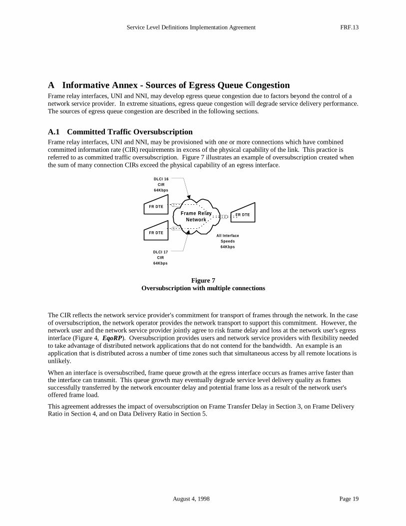
A Informative Annex - Sources of Egress Queue CongestionFrame relay interfaces, UNI and NNI, may develop egress queue congestion due to factors beyond the control of anetwork service provider. In extreme situations, egress queue congestion will degrade service delivery performance.The sources of egress queue congestion are described in the following sections.
A.1 Committed Traffic OversubscriptionFrame relay interfaces, UNI and NNI, may be provisioned with one or more connections which have combinedcommitted information rate (CIR) requirements in excess of the physical capability of the link. This practice isreferred to as committed traffic oversubscription. Figure 7 illustrates an example of oversubscription created whenthe sum of many connection CIRs exceed the physical capability of an egress interface.
FR DTE
Frame RelayNetwork
FR DTE
FR DTE
All InterfaceSpeeds64Kbps
DLCI 16CIR
64Kbps
DLCI 17CIR
64Kbps
Figure 7Oversubscription with multiple connections
The CIR reflects the network service provider's commitment for transport of frames through the network. In the caseof oversubscription, the network operator provides the network transport to support this commitment. However, thenetwork user and the network service provider jointly agree to risk frame delay and loss at the network user's egressinterface (Figure 4, EqoRP). Oversubscription provides users and network service providers with flexibility neededto take advantage of distributed network applications that do not contend for the bandwidth. An example is anapplication that is distributed across a number of time zones such that simultaneous access by all remote locations isunlikely.
When an interface is oversubscribed, frame queue growth at the egress interface occurs as frames arrive faster thanthe interface can transmit. This queue growth may eventually degrade service level delivery quality as framessuccessfully transferred by the network encounter delay and potential frame loss as a result of the network user'soffered frame load.
This agreement addresses the impact of oversubscription on Frame Transfer Delay in Section 3, on Frame DeliveryRatio in Section 4, and on Data Delivery Ratio in Section 5.
FRF.13 Service Level Definitions Implementation Agreement
Page 20 August 4, 1998
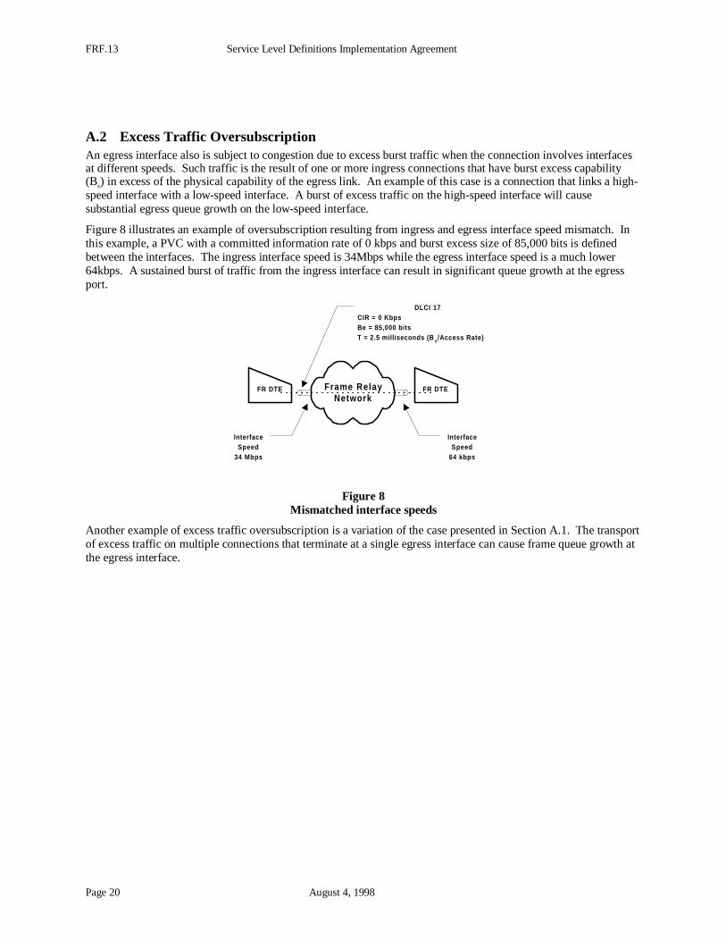
A.2 Excess Traffic OversubscriptionAn egress interface also is subject to congestion due to excess burst traffic when the connection involves interfacesat different speeds. Such traffic is the result of one or more ingress connections that have burst excess capability(Be) in excess of the physical capability of the egress link. An example of this case is a connection that links a high-speed interface with a low-speed interface. A burst of excess traffic on the high-speed interface will causesubstantial egress queue growth on the low-speed interface.
Figure 8 illustrates an example of oversubscription resulting from ingress and egress interface speed mismatch. Inthis example, a PVC with a committed information rate of 0 kbps and burst excess size of 85,000 bits is definedbetween the interfaces. The ingress interface speed is 34Mbps while the egress interface speed is a much lower64kbps. A sustained burst of traffic from the ingress interface can result in significant queue growth at the egressport.
Frame RelayNetwork
FR DTEFR DTE
DLCI 17CIR = 0 KbpsBe = 85,000 bitsT = 2.5 milliseconds (B e/Access Rate)
InterfaceSpeed
34 Mbps
InterfaceSpeed
64 kbps
Figure 8Mismatched interface speeds
Another example of excess traffic oversubscription is a variation of the case presented in Section A.1. The transportof excess traffic on multiple connections that terminate at a single egress interface can cause frame queue growth atthe egress interface.
Service Level Definitions Implementation Agreement FRF.13
August 4, 1998 Page 21
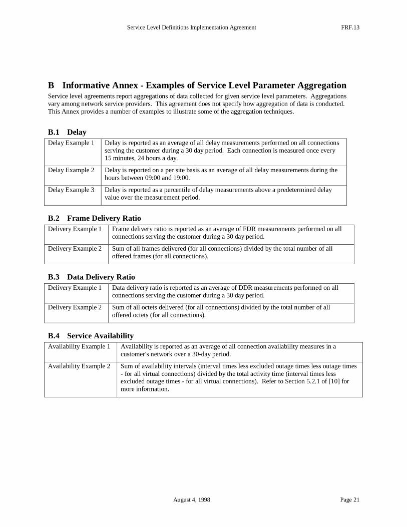
B Informative Annex - Examples of Service Level Parameter AggregationService level agreements report aggregations of data collected for given service level parameters. Aggregationsvary among network service providers. This agreement does not specify how aggregation of data is conducted.This Annex provides a number of examples to illustrate some of the aggregation techniques.
B.1 DelayDelay Example 1 Delay is reported as an average of all delay measurements performed on all connections
serving the customer during a 30 day period. Each connection is measured once every15 minutes, 24 hours a day.
Delay Example 2 Delay is reported on a per site basis as an average of all delay measurements during thehours between 09:00 and 19:00.
Delay Example 3 Delay is reported as a percentile of delay measurements above a predetermined delayvalue over the measurement period.
B.2 Frame Delivery RatioDelivery Example 1 Frame delivery ratio is reported as an average of FDR measurements performed on all
connections serving the customer during a 30 day period.
Delivery Example 2 Sum of all frames delivered (for all connections) divided by the total number of alloffered frames (for all connections).
B.3 Data Delivery RatioDelivery Example 1 Data delivery ratio is reported as an average of DDR measurements performed on all
connections serving the customer during a 30 day period.
Delivery Example 2 Sum of all octets delivered (for all connections) divided by the total number of alloffered octets (for all connections).
B.4 Service AvailabilityAvailability Example 1 Availability is reported as an average of all connection availability measures in a
customer's network over a 30-day period.
Availability Example 2 Sum of availability intervals (interval times less excluded outage times less outage times- for all virtual connections) divided by the total activity time (interval times lessexcluded outage times - for all virtual connections). Refer to Section 5.2.1 of [10] formore information.