service ll. - squarespace ll. iual , w ... name plate attached to it. the model and serial numbers...
TRANSCRIPT

EL EC TRI - SPREAD" PICK-UP SANDERS
SERIES II
Parts List &
Service LL. iual , w
MFR By: SMITH METAL WORKS OF NEWARK INC. RT 31 EAST NEWARK, NEW YORK STATE 145 13 PHONE: 315-331-1651 FAX: 31 5-331-0910
All *@Electri-Spread" Pick-up Sanders come equipped with a name plate attached to it. The model and serial numbers are stamped on the name plate. Always use t h e model and serial numbers in all correspondence regarding parts and or operation. All "Electri-Spreadqt Pick-up Sanders use either a 7 0 inch long conveyor frame (1/2 yd. and 1 yd.) or a 92 inch long conveyor frame (1 3 / 4 yd. and larger) . 10/2002

S/S SERIES I/ SANDERS PARTS LIST
DESRICPTION QIY 48T Sprocket (Elect) 1 24T Sprocket (Hyd) 1 8" V Pulley wlEiect. Clutch 1
12VDC Electric Motor 1 Hydraulic Motor 1 Gasoline Motor 10.5hp 1 Gasoline Motor 1 l hp Honda 1 Gearbox (HUBCITY W300) 1 Gearbox (DURST A21) start ser #4562 t Motor Mount 1 Drivelldler Sprocket 4 1" Pillow Block Brg 6 Replaceable Plastic Slider Bed 1-314&3Y( 1 Replaceable Plastic Slider Bed 112&1Yd 1 Conveyor Drag Chain 1-314 & 3Yd 1 Conveyor Drag Chain 112 & 3Yd 1 Hopper Flapper 1 Raurn Wipm 1 Skirt 1 Front Deflector (plastic) 1 Hinged Deflector 3 Rear Support Bracket 1 Gear Box Mount 1 Main Chain Cover 1-314 & 3 Yd 2 Main Chain Cover fYd 2 Main Chain Cover 112Yd 2 Hopper Door 1 Door Handle 1 Door Handle Clamping Nut 1 ElectlHyd Motor Mount Adapter 1 Motor Adapter-1 O.5hp Gas 1 Motor Adapter -Dual Hyd. 1 Bearing Bracket 3 Gearbox input shaft Ext. 1 Inverted V 1-314 & 3Yd 1 Inverted V 1Yd 1 Conveyor Shaft (Drive& Idler) 2 Spinner ShaR 1 Spinner Shaft - Extended 1 Spinner 1 Spinner Hub 7 Elmric Mtr. Sprocket 14T 1 Hydraulic Mtr. Sprocket 24T 1 Gasoline Mtr. Pulley 2 Dia. 1
16T Sprocket ( Elect.) 16T Sprocket (Hyd) 16T Sprocket (Gas)
Hopper Screen state size
24T Sprocket ( Elect.) 16T Sprocket ( Hyd ) 24T Sprocket ( Gas )
Spinner Chain (Elect.) 64 Pitches 1 Spinner Chain (Hyd) 50 Pitches 1 Spinner V-Belt (Gas) 112"x32" 1
Gearbox Chain Elect.) 74 Pitches 1 Gearbox Chain (Hyd) 74 Pitches 1 Gearbox Chain ( Gas ) 74 Pitches 1
Motor Cover 1,l-314 &3Yd Motor Cover 112 Yd
Rear Chain Cover
Installation Kit (Elect.) Installation Kit (Hyd) Installation Kit (Gas)
12" Spinner Extension Kit Complete 1 Brg. Plate Ass'y. (for above kit) 1 Chute Extension (for above) 1 Shaft Extension (for above) 1
Electric Throttle Motor (only ) 1 Electric Throttle Kit wlcontrols 1 6' Molded .Wire Connector (for motor) 1 25' Molded Wire Connector (for supply) 1 Replacement Caps (for above connector 1


I I I I ICtIARGE SUBASSEMBLY WITH .SINGLE HYDRAULIC MOTOR
d
B
1
I
# . \ I
120- 26-05 1 - I
. . Sm&h Metal Works Series I1 I ~ M W I N G 50 -:&/' 7: ;.,
. -3ib 3

, - Smith Metal Works Series II : I ~ G NO. SM 1 20 - A3
4

DISCHARGE SUBASSEMBLY WITH DUAL HYDRAULIC MOTOR I

Smith Metal Works Series I1 I D R A W ~ D NO. SMW120-B .MA,-. -.- - ,
R b.
. .
HOPPER SUBASSEMBLY 3

Smith Metal Works Series II

r
Smith Metal Works Series I1 ]DRAWING NO. SMW120-D L


SAFETY
1. Insure that a l l personnel involved with operation and maintenance of this equipment are properly* . - =
instructed.
2. Always disconnect all power sourcbs when servicing the unit.
3 . Avoid bodily contact and keep.al1 lmse clothing clear of moving parts when observing unit in operation.
4 . When loading and unloading unit ~ s e the list rings provided on the hopper s ides . Only a t t a p t to lift the unit when the hopper is empty. As always, NEVER STAND BENEATH a machine being lifted.
POWER REQUIREMENTS
Electric Models - A fully loaded "Electri-Spreadw Pick-up Sander will draw approximately 30-35 amperes. A 100 Amp, dual battery system is recommended.
Hydraulic Models - Minimum hydraulic source - 10 GFB! lS00 P s i Line size - 1/211 pressure, 3/41F return line.

INSTALLATION
PLACEMENT OF S A N D IN TRUCK All SERIES I1 "ELECTRI-SPREADB* SAPJDWS are shipped with two hardwood planks bolted to the bottom of the chassis. We recommend leaving these planks attached to the sander. They provide a surface to block against and help the conveyor return chain (or belt) remain clear of spillage.
Attach lifting chains or cable to the lift rings provided on the hopper sides. Place the sander on the truck centered and as far forward as possible. Use wood blocking to keep the sander from shifting on the truck bed. T i e down the sander with chains, using the turnbuckles provided with the u n i t . Note: over- tightening of turnbuckles m y cause distort ion of the sander.
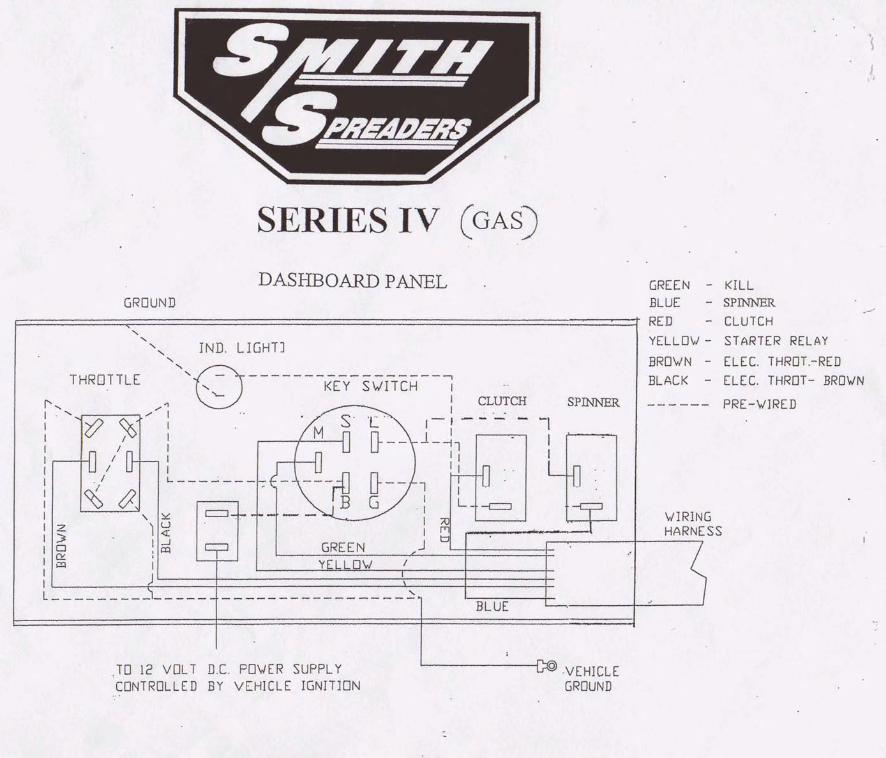
"HOOK-UP" INSTRUCTIONS
ELECTRIC MOTOR POWERED - Each "Electri-SpreadM Pick-Up Sander is sold w i t h an installation kit, complete with all el-rical components required for hook-up. Follow the instructions and wiring diagram included in the installation k i t and illustrated below.
GAS EHCINE POWERED - See instruction sheet enclos&d' in insta-llation kit.
HYDRAULIC MOTOR POWERED - Attach a l / Z m * hydraulic line to one hydraulic motor port. Attach a 3 / 4 " hydraulic line to the return port of the hydraulic motor, (If the motor runs in reverse, simply reverse the hoses.)


OPERATION
Once your "Ele~tri-Spread@~ Pick-Up Sander is properly installed, we recommend a "dry rantB with the h-per empty. Check for any obvious poor or faulty operation.
Load the hopper with your desired material and adjust the machine for proper "spread". Volume is controlled by the sluice gate opening, while direction and range is controlled by position of the internal chute and external deflectors. Always observe all safety rules when performing adjustments.
An inverted "VW is included as standard equipment. The purpose of the inverted taVw is t~ reduce load down pressure on the conveyor there*'lby-;e&sing start- up power requirements. If the laad exhibits excessive "bridging", the operator may elect to remove the inverted "Vut sacrificing power consumptian for improved product flow. In order to reduce power consumption on start-ups it is recommended that pay- load not be left in hopper over an extended period. (This might cause material freeze up.)
MAINTENANCE
Proper scheduled and perfo&ed dperatbr ma3ntenance is the key for successful operation.
Proper lubrication consists of keeping all grease fittings serviced. Also insure that the lubricant level in the gearbox is at tho &CIS plug level, (Use a Non-detergent 10 w e i g l l t in60@.'~&1 i n #e gearbox) I ,:
Frequent lubrication of the roller chains is also recommended.
Cleanliness of the unit helps minimLee friction. Always flush off the unit after operation to prevent build-up and binding.
Proper adjustments will keep the unit operating freely, Provide only the necessary chain and/or V- belt tension and conveyor tension to maintain smooth operation. Excessive tensions will only result in overloading the motor.

OFF-SEASON MAINTENANCE (SUMMER STORAGE)
Thoroughly flush tho entire uni t c16an af sa l t and sand. Lube a l l bearings and check geagbox lube level. we strongly recommend removal of alk'xaller chains and conveyor chain a@ store i m e d d - i n oil. Failure to remove and thoroughly lubricate chains will result in an inoperative sander next season!
WARRANTY SMITH METAL WORKS warrants our products to be free from defects in material and workmanship for a period of 1 (one) year from t i m e of purchase. This warranty is limited to the repair or replacement of products failing under normal use and operation of equipment. The defective part(s) and a copy af the original paid invoice or bill of sale must be returned to the factory for repair ar replacement.

CANIMEX 8039 GEARBOX - HOLLOW BORE PARTS LIST

DURST A21 GEARBOX PARTS LIST
PART # 1 2012%
1 2 3
8 .- ,
- . 9 10 I1 12 13 14 15 16 17 18 19 20 21
DESCRIPTION
HOUSING 1 COVER 1 WORM GEAR 1
- worn 1 BEARING CONE (TIMKEN 15101) 4 BEARING CUP (TIMKEN 15245) 4 S N A P RING, INPUT (5422) 1 SNAP RING, INPUT & O ~ U T (1208-8) 4 CAP SCREW (3/8-16 X 3/4) 4 SHAFT, INBUT 1 WOODRUFF KEY (807) 114 X 7/8 I WOODRUFF KEY (809) 1/4 X 1 118 1 SEAL, INPUT & OUTPUT (NOK AEl452E) 2 PLUG, DRAIN & LEVEL 2 GASKET, COVER 1 PLUG, VENT 1 m3WNGSWIEL;n 1 CAP, INPUT &'OUTPUT 2 GREASE ZERK 1 NILOS RING, INPUT 1 SHIM (-020) rn
1/8-27 NPTF
~ l . 0 @ StiA71 WITH 8 6 0 EX~INSlON
775 FJLI DEPTH 1 / 1 * 1/6 K E I V A Y
S C T I O N A - A