service manual - avengrid · basic principles of operation and work proce-dures. they may not...
TRANSCRIPT

SE
RV
ICE
MA
NU
AL
99000-94310
SERVICE MANUAL
HYOSUNG MOTORS & MACHINERY INC.
CHASSIS
ELECTRICAL SYSTEM
GGRROOUUPP IINNDDEEXX
GENERAL INFORMATION 1
PERIODIC MAINTENANCE 2
ENGINE 3
FUEL SYSTEM 4
5
6
SERVICING INFORMATION 7
� This manual has been prepared on the basis of the latest specification at the time of publica-tion.If modification has been made since then, dif-ference may exist between the content of thismanual and the actual vehicle.
� Illustrations in this manual are used to show the basic principles of operation and work proce-dures.They may not represent the actual vehicle exactlyin detail.
� This manual is intended for those who haveenough knowledge and sk i l ls for serv ic ing HYOSUNG vehicles. Without such knowledge andskills, you should not attempt servicing by relyingon this manual only.Instead, please contact your nearby authorizedHYOSUNG motorcycle dealer.
� COPYRIGHT HYOSUNG MOTORS & MACHINERY INC. 2001.
HYOSUNG MOTORS & MACHINERY INC. Overseas Technical Department
FFOORREEWWOORRDD
This manual contains an introductory description on HYOSUNG 『 』and procedures for its inspection/service and overhaul of its main components.Other information considered as generally known isnot included.Read GENERAL INFORMATION section to familiarizeyourself with out l ine of the vehicle and MAINTE-NANCE and other sect ions to use as a guide forproper inspection and service.This manual will help you know the vehicle better sothat you can assure your customers of your optimum and quick service.
COPYRIGHTED

HHOOWW TTOO UUSSEE TTHHIISS MMAANNUUAALL
TO LOCATE WHAT YOU ARELOOKING FOR:1. The text of this manual is divided into sections.2. As the title of these sections are listed on the previous
page as GROUP INDEX, select the section where you are look-ing for.
3. Holding the manual as shown at the right will allow you to findthe first page of the section easily.
4. On the first page of each section, its contents are listed. Findthe item and page you need.
SYMBOLListed in the table below are the symbols indicating instructions and other information necessary for servicing and meaning associated with them respectively.
Apply THREAD LOCK “1324”.
Apply or use brake fluid.
Measure in voltage range.
Measure in resistance range.
Measure in current range.
Use special tool.
Torque control required.Data beside it indicates specified torque.
Apply oil. Use engine oil unless otherwisespecified.
Apply SUPER GREASE “A”.
Apply SILICONE GREASE.
Apply MOLY PASTE.
Apply BOND “1215”.
DEFINITIONSYMBOL DEFINITIONSYMBOL
Apply SUPER GREASE “C”.COPYRIGHTED

①
③
④
⑤⑤
⑧⑦
⑧⑦
④
②
⑥
⑥
�
�
�
�
��
�
COMPONENT PARTS AND WORK TO BE DONE
Under the name of each system or unit, its exploded view is provided with work instruction and other service informationsuch as the tightening torque, lubricating points and looking agent points.
Example : STEERING AND FRONT SUSPENSION
TIGHTENING TORQUE
ITEM N∙∙m
18 ~ 28
18.4 ~ 28.6 1.84 ~ 2.86
22.4 ~ 35.7
40 ~ 50
80 ~ 100
22 ~ 35
22 ~ 35
40 ~ 60
� : ASSEMBLING APPLY GREASE� : ASSEMBLING APPLY GREASE� : APPLY GREASE TO LIPS � : APPLY GREASE� : ASSEMBLING APPLY GREASE
1.8 ~ 2.8
2.24 ~ 3.57
4.0 ~ 5.0
8.0 ~ 10.0
2.2 ~ 3.5
2.2 ~ 3.5
4.0 ~ 6.0
kg∙∙m
①
②
③
④
⑤
⑥
⑦
⑧
COPYRIGHTED

COPYRIGHTED

GGEENNEERRAALL IINNFFOORRMMAATTIIOONN
INFORMATION LABELS 1-1
GENERAL PRECAUTIONS 1-1
SERIAL NUMBER LOCATION 1-4
FUEL AND OIL RECOMMENDATIONS 1-5
EXTERIOR ILLUSTRATION 1-6
SPECIFICATIONS 1-7
CONTENTS
1
COPYRIGHTED

1-1 GENERAL INFORMATION
Indicates a potential hazard that could result in vehicle damage.
NOTE :Indicates special information to make maintenance easier or instructions cleaner.
Please note, however, that the WARNING and CAUTION contained in this manual cannot possibly cover all potential hazards relating to the servicing, or lack of servicing, of the motorcycle. In addition to the WARNING and CAUTION stated, you must use good judgement and basic mechanical safety principles. If you are unsure about how to perform aparticular service operation, ask a more experienced mechanic for advice.
GENERAL PRECAUTIONS
CAUTION
WARNING
WARNING / CAUTION / NOTE
Please read this manual and follow its instructions carefully. To emphasize special information, the symbol and the words WARNING, CAUTION and NOTE have special meanings. Pay special attention to the messages highlighted by these signal words.
� Proper service and repair procedures are important for the safety of the service machanic and the safetyand reliability of the vehicle.
� When 2 or more persons work together, pay attention to the safety of each other.� When it is necessary to run the engine indoors, make sure that exhaust gas is forced outdoors.� When working with toxic or flammable materials, make sure that the area you work in is well-ventilated
and that you follow all off the material manufacturer’s instructions.� Never use gasoline as a cleaning solvent.� To avoid getting burned, do not touch the engine, engine oil or exhaust system during or for a while
after engine operation.� After servicing fuel, oil, exhaust or brake systems, check all lines and fittings related to the system for
leaks.
WARNING
Indicates a potential hazard that could result in death or injury.
COPYRIGHTED

GENERAL INFORMATION 1-2
� If parts replacement is necessary, replace the parts with HYOSUNG Genuine Parts or their equivalent.� When removing parts that are to be reused, keep them arranged in an orderly manner so that they may be
reinstalled in the proper order and orientation.� Be sure to use special tools when instructed.� Make sure that all parts used in reassembly are clean, and also lubricated when specified.� When use of a certain type of lubricant, bond, or sealant is specified, be sure to use the specified type.� When removing the battery, disconnect the negative cable first and then positive cable. When reconnect-
ing the battery, connect the positive cable first and then negative cable, and replace the terminal cover on the positive terminal.
� When performing service to electrical parts, if the service procedures do not require use of bat-tery power, diconnect the negative cable at the battery.
� Tighten cylinder head and case bolts and nuts, beginning with larger diameter and ending with smaller diameter, from inside to outside diagonally, to the specified tightening torque.
� Whenever you remove oil seals, gaskets, packing, O-rings, locking washers, cotter pins, circlips, andcertain other parts as specified, be sure to replace them with new ones. Also, before installing these new parts, be sure to remove any left over material from the mating surfaces.
� Never reuse a circlip. When installing a new circlip, take care not to expand the end gap larger thanrequired to slip the circlip over the shaft. After installing a circlip, always ensure that it is completely seat-ed in its groove and securely fitted.
� Do not use self-locking nuts a few times over.� Use a torque wrench to tighten fasteners to the torque values when specified. Wipe off grease or oil
if a thread is smeared with them.� After reassembly, check parts for tightness and operation.
� To protect environment, do not unlawfully dispose of used motor oil and other fluids: batteries, and tires.� To protect Earth’s natural resouces, properly dispose of used vehicles and parts.
CAUTION
COPYRIGHTED

1-3 GENERAL INFORMATION
HYOSUNG
NOTE :Difference between photographs and actual vehicles depends on the markets.
COPYRIGHTED

GENERAL INFORMATION 1-4
SERIAL NUMBER LOCATION
The frame serial number or V.I.N. (Vehicle Identification Number) is stamped on the front frame member. The engine seri-al number is stamped on the right side of crankcase assembly.These numbers are required especially for registering the machine and ordering spare parts.
◉ FRAME SERIAL NUMBER
◉ ENGINE SERIAL NUMBER
COPYRIGHTED

Grade
SF or SG
10W/30 or 10W/40
Classification system
API
SAE
� If an SAE 10W/40 motor oil is not available, select an alternative according to the following chart.
FUEL AND OIL RECOMMENDATIONS
◉ FUELGasoline used should be graded 85~95 octane or higher. An unleaded type gasoline is recommended. Ifengine pinging is experienced, substitute another brand as there are differences between brands.
◉ ENGINE OILUse HYOSUNG HYPOL OIL HS.I f they are not available, use a good quality TWO-STROKE engine oil.
◉ TRANSMISSION OILUse a good quality SAE 10W/30 or 10W/40 multigrade motor oil.
1- 5 GENERAL INFORMATION
COPYRIGHTED

EXTERIOR ILLUSTRATION
GENERAL INFORMATION 1- 6(H
EIG
HT)
(WID
TH
)
(WHEEL BASE)
(LENGTH)
658
670
820
865
658
825
120
645
950
1,355
COPYRIGHTED
1- 7 GENERAL INFORMATION
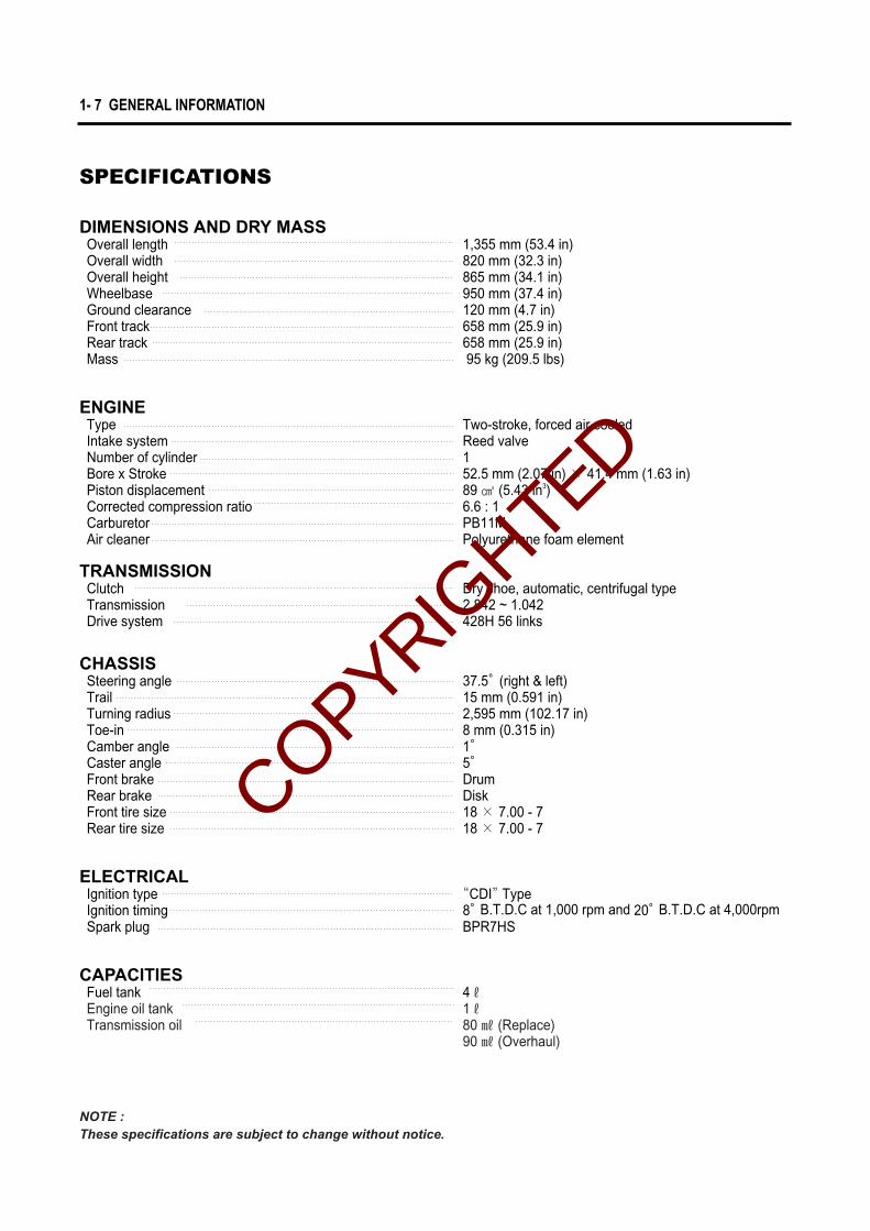
SPECIFICATIONS
DIMENSIONS AND DRY MASSOverall length 1,355 mm (53.4 in) Overall width 820 mm (32.3 in)Overall height 865 mm (34.1 in)Wheelbase 950 mm (37.4 in)Ground clearance 120 mm (4.7 in)Front track 658 mm (25.9 in)Rear track 658 mm (25.9 in)Mass 95 kg (209.5 lbs)
ENGINEType Two-stroke, forced air cooledIntake system Reed valveNumber of cylinder 1Bore x Stroke 52.5 mm (2.07 in) × 41.4 mm (1.63 in)Piston displacement 89 ㎤ (5.43 in3)Corrected compression ratio 6.6 : 1Carburetor PB11MAir cleaner Polyurethane foam element
TRANSMISSIONClutch Dry shoe, automatic, centrifugal typeTransmission 2.842 ~ 1.042Drive system 428H 56 links
CHASSISSteering angle 37.5。(right & left)Trail 15 mm (0.591 in)Turning radius 2,595 mm (102.17 in)Toe-in 8 mm (0.315 in)Camber angle 1。Caster angle 5。Front brake DrumRear brake DiskFront tire size 18 × 7.00 - 7Rear tire size 18 × 7.00 - 7
ELECTRICALIgnition type “CDI”TypeIgnition timing 8。B.T.D.C at 1,000 rpm and 20。B.T.D.C at 4,000rpmSpark plug BPR7HS
CAPACITIESFuel tank 4ℓEngine oil tank 1ℓTransmission oil 80 ㎖ (Replace)
90 ㎖ (Overhaul)
NOTE : These specifications are subject to change without notice.
COPYRIGHTED

PERIODIC MAINTENANCE SCHEDULE 2- 1
PERIODIC MAINTENANCE CHART 2- 1
LUBRICATION POINTS 2- 2
MAINTENANCE PROCEDURES 2- 3
AIR CLEANER 2- 3
CYLINDER HEAD NUTS 2- 4
CYLINDER HEAD AND CYLINDER 2- 4
SPARK PLUG 2- 5
CARBURETOR 2- 6
FUEL LINE 2- 6
TRANSMISSION OIL 2- 7
BRAKES 2- 7
DRIVE CHAIN 2-10
TIRE 2-11
STEERING 2-12
CHASSIS BOLTS AND NUTS 2-12
CCOONNTTEENNTTSS
2
PPEERRIIOODDIICC MMAAIINNTTEENNAANNCCEE
COPYRIGHTED
2-1 PERIODIC MAINTENANCE
ItemInitial 1 month Every 3 months Every 6 months page
Interval
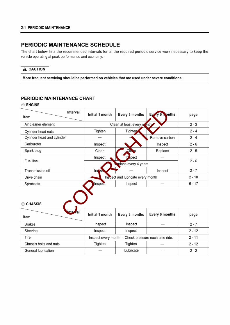
Air cleaner element
Cylinder head nuts
Cylinder head and cylinder
Carburetor
Spark plug
Fuel line
Transmission oil
Drive chain
Sprockets
Replace every 4 years
Inspect and lubricate every month
ItemInitial 1 month Every 3 months Every 6 months page
Interval
Brakes
Steering
Tire
Chassis bolts and nuts
General lubrication
Inspect
Inspect
Tighten
─
Inspect
Inspect
Tighten
Lubricate
─
─
─
─
Inspect every month ∙Check pressure each time ride.
◉ CHASSIS
2 - 7
2 - 12
2 - 11
2 - 12
2 - 2
PERIODIC MAINTENANCE SCHEDULEThe chart below lists the recommended intervals for all the required periodic service work necessary to keep the vehicle operating at peak performance and economy.
PERIODIC MAINTENANCE CHART◉ ENGINE
Clean at least every month
More frequent servicing should be performed on vehicles that are used under severe conditions.
CAUTION
Tighten
─
Inspect
Clean
Inspect
Inspect
Inspect
Tighten
─ Remove carbon
Inspect
Replace
─
Inspect
─
2 - 4
2 - 6
2 - 5
2 - 6
2 - 7
2 - 10
6 - 17
2 - 4
2 - 3
─
─
Clean
Inspect
─
Inspect
COPYRIGHTED

NOTE :� Before lubricating each part, clean off any rusty spots and wipe off any grease, oil, dirt or grime.� Lubricate exposed parts which are subject to rust, with either motor oil or grease whenever the vehicle has
been operated under wet or rainy condition.
PERIODIC MAINTENANCE 2-2
LUBRICATION POINTSProper lubrication is important for smooth operation and long life of each working part of the vehicle.Major lubrication points are indicated below.
① King pin② Front wheel bearing③ Steering shaft holder ④ Drive chain ⑤ Rear axle housing⑥ Rear brake cable
⑦ Front brake cable⑧ Throttle cable⑨ Throttle lever⑩ Front brake cam shaft
O - Motor oil, G - Grease
COPYRIGHTED

2-3 PERIODIC MAINTENANCE
MAINTENANCE PROCEDURES
AIR CLEANER
NOTE :Clean at least Every month.
If the air cleaner is clogged with dust, intake resis-tance wi l l increased with a resultant decrease inoutput and an increase in fuel consumption.Check and clean the element in the following man-ner.
● Stand the vehicle in the standing position.
● Remove the four bolts ①.
● Remove the clamp screw ②.● Remove the air cleaner case ⑤.● Remove the element ④ from the cap ③.● Fill a washing pan of a proper size with nonflammable
cleaning solvent. Immerse the element in the cleaningsolvent and wash it clean.
● Squeeze the cleaning solvent out of the washed elementby pressing it between the palms of both hands : do nottwist or wring the element or it will develop tears.
● Immerse the element in HYOSUNG genuine oil andsqueeze the oil out of the element leaving it slightly wetwith oil.
● Fit the cleaner element to frame properly.
��Before and during the cleaning operation,inspect the element for tears. A torn elementmust be replaced.
�� Be sure to position the element snugly and cor-rectly, so that no incoming air will bypass it.Remember, rapid wear of piston rings andcylinder bore is often caused by a defective orpoorly fitted element.
CAUTION
� Non-flammable cleaning solvent� 2-stroke engine oil.
COPYRIGHTED

PERIODIC MAINTENANCE 2-4
CYLINDER HEAD NUTS
NOTE :Tighten Initial 1 month and Every 3 months.
Cylinder head nuts, when they are not tightened tothe specif ied torque, may result in leakage of thecompressed mixture and reduce output.First loosen the nuts and tighten the 4 nuts evenlyone by one in stages until each one is tightened tothe specified torque. Tighten the nuts in the orderindicated.
Cylinder head nut : 18~28 N∙m (1.8~2.8 kg∙m)
CYLINDER HEAD AND CYLINDER
NOTE :Remove carbon Every 6 months.
Carbon deposi ts in the combust ion chamber andthe cylinder head wil l raise the compression ratioand may cause pre-ignition or overheating. Carbondeposited at the exhaust port of the cyl inder wi l lprevent the f low of exhaust gases, reducing theoutput. Remove carbon deposits periodically.
COPYRIGHTED

TYPE SPARK PLUG SPECIFICATION
2-5 PERIODIC MAINTENANCE
● Check spark plug for burnt condition. If abnormal,replace the plug as indicated below.
BPR6HS
BPR7HS
BPR8HS
Hot type
Standard type
Cold type
Thickness gauge : 09900-20804
Spark plug : 25~30 N∙m (2.5~3.0 kg∙m)
SPARK PLUG
NOTE :Inspect Initial 1 month and Every 3 months,Replace Every 6 months.
Neglecting the spark plug maintenance eventuallyleads to difficult starting and poor performance. If thespark plug is used for a long period, the electrode grad-ually burns away and carbon builds up along the insidepart. In accordance with the Periodic Inspection Chart,the plug should be removed for inspection, cleaningand resetting the gap.● Carbon deposits on the spark plug will prevent good
sparking and cause misfiring. Clean the deposits offperiodically.
● If the center electrode is fairly worn down, the plugshould be replaced and the plug gap set to the speci-fied gap using a thickness gauge.
0.6�0.7 mm(0.024~0.028 in)
Spark plug gap
●● To check the spark plug, first make sure that thefuel used is unleaded gasoline, and if plug iseither sooty with carbon or burnt white, replaceit.
●● Confirm the thread size and reach when replac-ing the plug.
CAUTION
0.6�0.7 mm(0.024~0.028 in)
COPYRIGHTED
PERIODIC MAINTENANCE 2-6
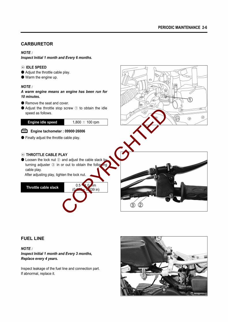
CARBURETOR
FUEL LINE
NOTE :Inspect Initial 1 month and Every 3 months,Replace every 4 years.
Inspect leakage of the fuel line and connection part.If abnormal, replace it.
Engine tachometer : 09900-26006
1,800 ± 100 rpmEngine idle speed
0.5 ~ 1.0 mm(0.020 ~ 0.039 in)Throttle cable slack
◉ IDLE SPEED● Adjust the throttle cable play.● Warm the engine up.
NOTE : Inspect Initial 1 month and Every 6 months.
NOTE :A warm engine means an engine has been run for10 minutes.
● Remove the seat and cover.● Adjust the throttle stop screw ① to obtain the idle
speed as follows.
● Finally adjust the throttle cable play.
◉ THROTTLE CABLE PLAY● Loosen the lock nut ② and adjust the cable slack by
turning adjuster ③ in or out to obtain the followingcable play.After adjusting play, tighten the lock nut.
COPYRIGHTED

2-7 PERIODIC MAINTENANCE
After a long period of use, the transmission oil qual-ities will deteriorate and quicken the wear of slidingand interlocking surfaces. Replace the transmissionoil periodically following the procedure below.● Start the engine to warm up the oil, this will facilitate
draining of oil.● Unscrew the oil filler cap ① and drain plug ②, and
drain the oil completely.● Tighten the drain plug.● Supply a good quality SAE 10W/30 or 10W/40 multi-
grade motor oil.
BRAKES
NOTE :Inspect Initial 1 month and Every 3 months.
◉ FRONT BRAKE
■■ BRAKE ADJUSTMENT
Adjust the free play ④ to 5 ~ 15mm (0.197 ~ 0.591 in)by screwing in or out the front brake adjust nut ⑤.
TRANSMISSION OIL
NOTE :Inspect Initial 1 month and Every 6 months.
TRANSMISSION OIL CAPACITY
80 ㎖90 ㎖
Change
Overhaul
5 ~ 15 mm (0.197 ~ 0.591 in)
Front brake lever play
● Check the oil level with the oil level screw ③ .
5 ~ 15 mm (0.197 ~ 0.591 in)
COPYRIGHTED
PERIODIC MAINTENANCE 2-8
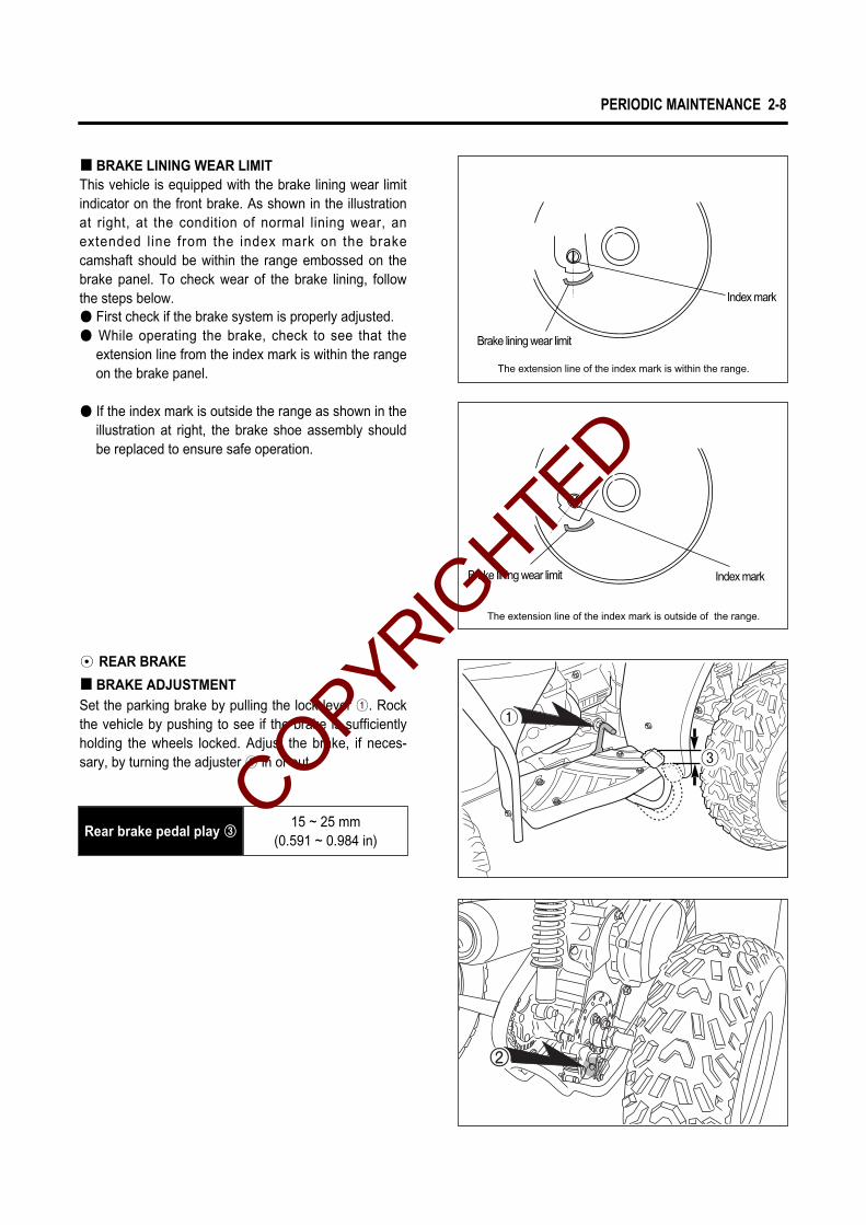
◉ REAR BRAKE
■■ BRAKE ADJUSTMENTSet the parking brake by pulling the lock lever ①. Rockthe vehicle by pushing to see if the brake is sufficientlyholding the wheels locked. Adjust the brake, if neces-sary, by turning the adjuster ② in or out.
■■ BRAKE LINING WEAR LIMITThis vehicle is equipped with the brake lining wear limitindicator on the front brake. As shown in the illustrationat right, at the condition of normal lining wear, anextended line from the index mark on the brakecamshaft should be within the range embossed on thebrake panel. To check wear of the brake lining, followthe steps below.● First check if the brake system is properly adjusted.● While operating the brake, check to see that the
extension line from the index mark is within the rangeon the brake panel.
● If the index mark is outside the range as shown in theillustration at right, the brake shoe assembly shouldbe replaced to ensure safe operation.
15 ~ 25 mm (0.591 ~ 0.984 in)
Rear brake pedal play ③③
Brake lining wear limit
The extension line of the index mark is within the range.
The extension line of the index mark is outside of the range.
Index mark
Brake lining wear limit Index mark
①
③
COPYRIGHTED

2-9 PERIODIC MAINTENANCE
■■ BRAKE PAD WEARThe extend of brake pad wear can be checked by observ-ing the grooved limit � on the pad. When the wearexceeds the grooved limit, replace the pads with newones.
■■ REAR BRAKE PAD REPLACEMENT
● Remove the brake caliper.● Remove the brake pads.● To reassmble, reverse the above sequence.
Replace the brake pad as a set, otherwise brakingperformance will be adversely affected.
CAUTION
Rear brake caliper mounting bolt: 5.0~7.0 N∙m (0.5~0.7 kg∙m)
�
COPYRIGHTED

PERIODIC MAINTENANCE 2-10
DRIVE CHAIN
NOTE :Inspect and lubricate Every month.
Visually check the drive chain for the possible defects listedbelow.
1. Loosen pins2. Damaged rollers3. Dry or rusted links4. Kinked or binding links5. Excessive wearIf any defects are found, the drive chain must bereplaced.
◉◉ LUBRICATING THE DRIVE CHAINDirt hastens wear of drive chain and sprockets.Lubricate the drive chain with chain lube or motor oil fre-quently. Every 1 month or more frequently, wash thechain clean in a pool of solvent and lubricate it withchain lube or motor oil. In a dusty area, this serviceshould be given at shorter intervals.
◉ DRIVE CHAIN REPLACEMENTThe drive chain is checked when its slack (between twosprockets) is within 5~15 mm (0.197~0.591 in) range.
When refitting the drive chain, be sure to installthe chain joint clip as shown : the slit end facescounter to turning direction.
CAUTION
5 ~ 15 mm (0.197 ~ 0.591 in)
Drive chain slack
If the drive chain slack exceeds the specification, thechain must be replaced.
5~15 mm
(0.197~0.591 in)
COPYRIGHTED

2-11 PERIODIC MAINTENANCE
◉TIRE TREAD CONDITIONOperating the vehicle with excessively worn tires willdecrease riding stability and consequently invite a dan-gerous situation. It is highly recommended to replacethe tire when the remaining depth of tire tread reachesthe following specifications.
TIRE
NOTE :Inspect Every month. Check pressure each timeride.
◉TIRE PRESSUREIf the tire pressure is too high, the vehicle will tend toride stiffly, have poor traction. Conversely, if the tirepressure is too low, stability will be adversely affected.Therefore, maintain the correct tire pressure for goodtraction and prolonging tire life.
Front
Rear
COLD INFLATION TIRE PRESSURE
The standard tire fitted on this 『『ATV』』is 18×7.00 -7 for front and rear. The use of a tire other than thestandard may cause handling instability. It is high-ly recommended to use a HYOSUNG Genuine Tire.
CAUTION
kPa
25
25
kgf/㎠
0.25
0.25
psi
3.6
3.6
Service limit
10 mm (0.394 in)Front and rear tire tread depth
COPYRIGHTED

PERIODIC MAINTENANCE 2-12
STEERING
NOTE :Inspect Initial 1 month and Every 3 months.
Steering system should be adjusted properly forsmooth manipulation of handlebars and safe running.
CHASSIS BOLTS AND NUTS
NOTE :Tighten Initial 1 month and Every 3 months.
Check that all chassis bolts and nuts are tightened totheir specified torque. (Refer to page 7-9)
◉ TOE-IN● Place the vehicle on the level ground.● Make sure that the tire pressure is within speci-
fication.(Refer to page 2-11)
8.0 mm(0.315 in)
Toe - in
● The front wheels are set in straight-ahead position.● Measure the distance (A and B in illustration) of
front wheels with a gauge as shown in illustra-tion and calculate the difference between A andB.
● If the toe-in is off the specification, bring it intothe specified range. (Refer to page 6-11)
ForwardCOPYRIGHTED

COPYRIGHTED

EENNGGIINNEE
3
ENGINE REMOVAL AND REINSTALLATION 3- 1
ENGINE REMOVAL 3- 1
ENGINE REINSTALLATION 3- 5
ENGINE DISASSEMBLY 3- 6
ENGINE COMPONENTS INSPECTION AND SERVICING 3-16
BEARINGS 3-16
OIL SEALS 3-16
CRANKSHAFT 3-16
AUTOMATIC CLUTCH INSPECTION 3-17
CYLINDER HEAD 3-20
CYLINDER 3-21
PISTON 3-21
REED VALVE 3-24
ENGINE REASSEMBLY 3-24
OIL SEALS 3-24
BEARINGS 3-25
BUSHINGS 3-25
CRANKSHAFT 3-26
CRANKCASE 3-27
TRANSMISSION 3-28
STARTER PINION, STARTER DRIVEN GEAR AND
STARTER MOTOR 3-30
MOVABLE DRIVEN AND CLUTCH 3-32
MOVABLE DRIVE 3-36
MAGNETO 3-38
PISTON 3-39
OIL PUMP AND INTAKE PIPE 3-41
COOLING FAN 3-42
MUFFLER 3-43
CONTENTS
COPYRIGHTED

3-1 ENGINE
ENGINE REMOVAL AND REINSTALLATION
ENGINE REMOVAL
Before taking the engine out of the frame, thoroughlyclean the engine with a suitable cleaner and drain trans-mission oil, etc. The procedure of engine removal issequentially explained in the following steps, and enginereinstallation is effected by reversing the removal proce-dure.
● Place an oil pan under the engine and remove the oilfiller cap and the oil drain plug to drain out transmis-sion oil.
● Remove the seat and frame cover.
● Turn the fuel cock to “OFF”position.
● Remove the fuel hoses from the fuel cock andremove the fuel tank by removing mounting bolts.
● Remove the muffler and exhaust pipe.
COPYRIGHTED

ENGINE 3-2
● Remove the engine ground lead wire ①.
● Remove the spark plug cap ②.
● Remove the starter motor lead wire ③.
● Disconnect the magneto coil lead wire ④.
COPYRIGHTED

3-3 ENGINE
● Remove the carburetor assembly from the intakepipe.
● Disconnect the oil hose and oil pump cable from theoil pump.
● Disconnect the thermoelement coupler ①.
● Remove the air cleaner ② and air cleaner chamber ③.
COPYRIGHTED
ENGINE 3-4
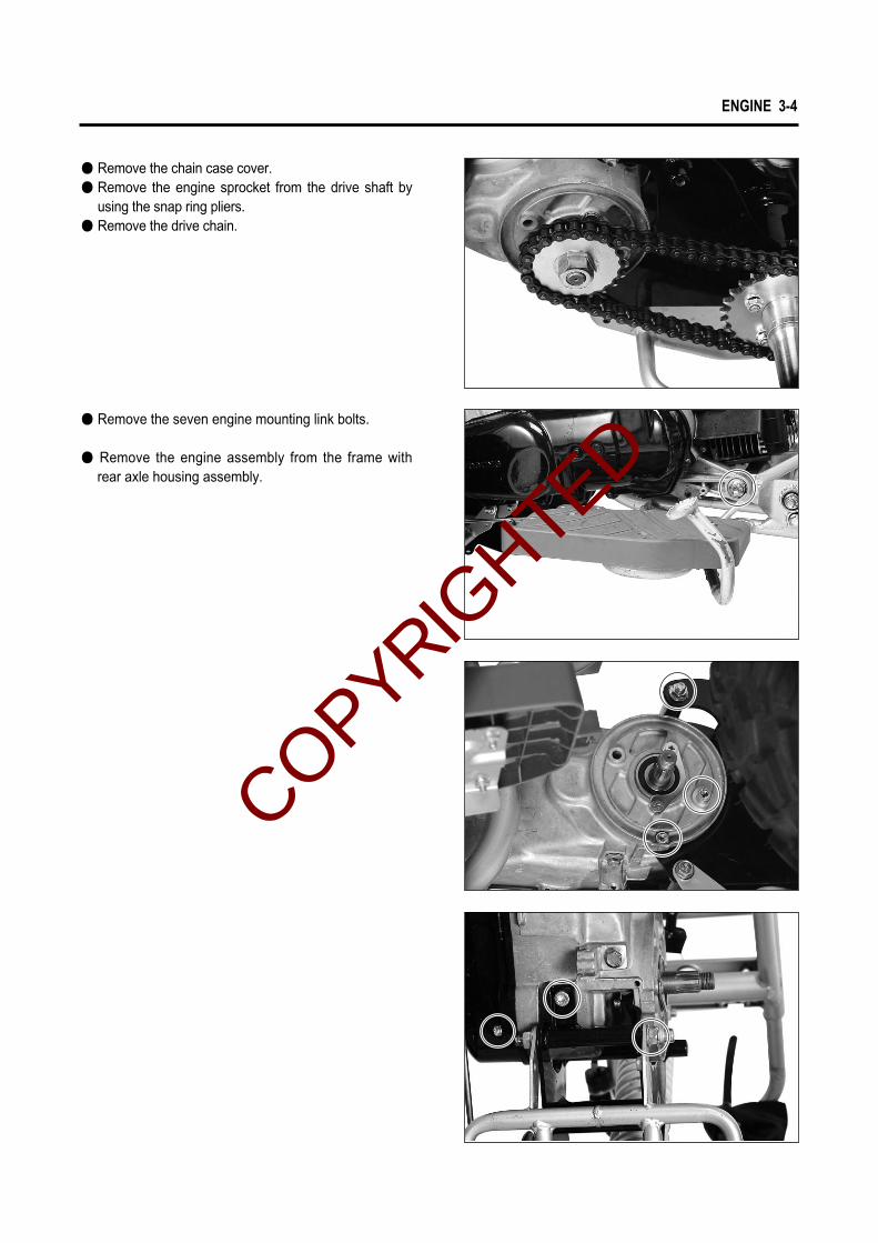
● Remove the seven engine mounting link bolts.
● Remove the engine assembly from the frame withrear axle housing assembly.
● Remove the chain case cover.● Remove the engine sprocket from the drive shaft by
using the snap ring pliers.● Remove the drive chain.
COPYRIGHTED

� Throttle cable Refer to page 2- 6 � Idling adjustment Refer to page 2- 6 � Front brake cable Refer to page 2- 7 � Rear brake cable Refer to page 2- 8 � Drive chain Refer to page 2-10
Engine mounting link bolt: 70 ~ 100 N∙m (7.0 ~ 10.0 kg∙m)
3-5 ENGINE
ENGINE REINSTALLATION
For remount ing eng ine , reverse the o rder o fengine removal and take the following additionalsteps.
● Install the engine mounting link bolts.(Refer to page 3-4)
● Install 90ml of transmission oil SAE 10W/30 or10W/40 multi-grade motor oil when engine is over-hauled, check the oil level.
● Set the fuel cock to “ON”position and start theengine.
● After remounting the engine, route wiring harnessand cables properly by referring to the sections,wire routing and cable routing, and adjust the fol-lowing items to the specification.
90 mlTransmission oil capacity(when overhauling engine)
COPYRIGHTED

ENGINE 3-6
ENGINE DISASSEMBLY
◉ MUFFLER● Remove the muffler removing the bolts.
◉ CYLINDER● Remove the cylinder cowling.● Remove the cylinder head ① and cylinder ②.
◉ PISTON● Place a cloth beneath the piston and remove the pis-
ton pin circlip ③ with a long-nose pliers.● Remove the piston pin ④ and piston ⑤.● Remove the piston pin bearing ⑥.
7①
②
COPYRIGHTED

3-7 ENGINE
● Remove the oil pump driven gear ④.
● Remove the reed valve ③.
◉ MAGNETO● Remove the cooling fan.● Remove the magneto rotor nut with the special tool.
Conrod holder : 09910-20115
◉ INTAKE PIPE AND OIL PUMP● Remove the intake pipe ① and oil pump ②.
②
④COPYRIGHTED

ENGINE 3-8
◉ MOVABLE DRIVE FACE● Remove the clutch cover.
● Remove the fixed drive face ② and V-belt ③.● Disassemble the movable drive face ④.
● Remove the fixed drive face nut ① with the specialtool.
This nut has left-hand thread.
CAUTION
Conrod holder : 09910-20115
● Remove the magneto rotor with the special tool.
● Remove the magneto stator and key.
Rotor remover sliding shaft : 09930-30102Rotor remover : 09930-30163
COPYRIGHTED
3-9 ENGINE
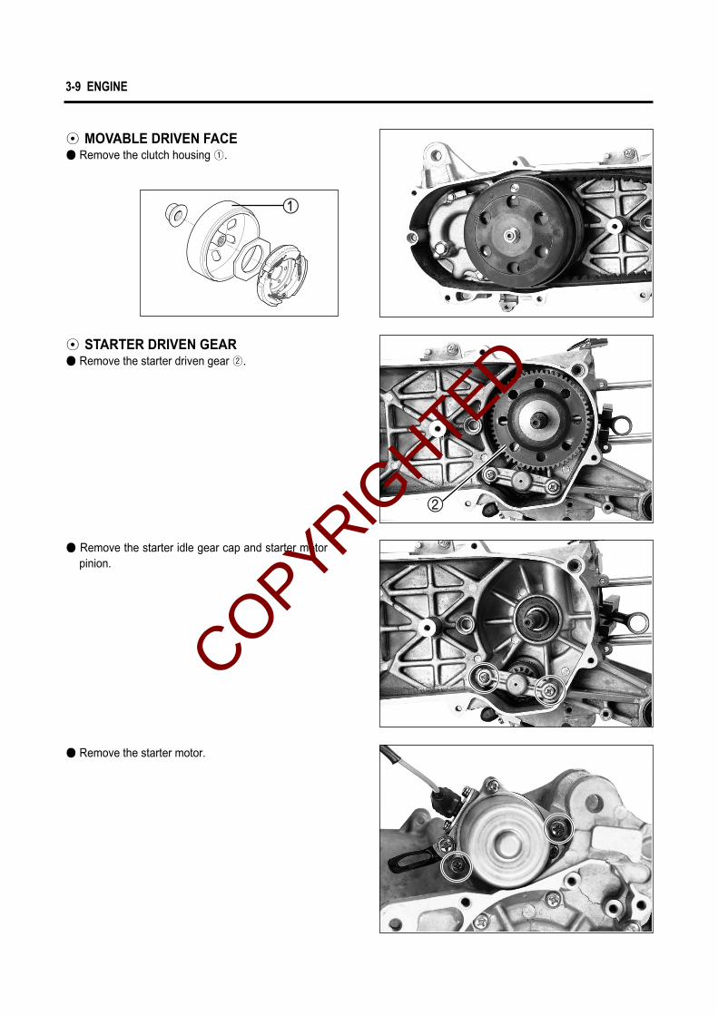
◉ STARTER DRIVEN GEAR● Remove the starter driven gear ②.
● Remove the starter idle gear cap and starter motorpinion.
● Remove the starter motor.
◉ MOVABLE DRIVEN FACE● Remove the clutch housing ①.
COPYRIGHTED

ENGINE 3-10
① Nut② Clutch shoe assembly③ Spring
● Remove the nut while holding down the clutch shoeassembly by both hands as shown in the illustration.
● Remove the pins ⑤, movable driven face ⑥ and fixeddriven face ⑦.
● Loosen the clutch shoe nut with the special tool.
Rotor holder : 09930-40113
Gradually back off the clutch shoe assemblypressed down by hand to counter the clutch springload. Releasing the hand suddenly may cause theparts to fly apart.
WARNING
①
③
②
● Using a thin blade screwdriver or the like, pry up themovable driven face spring guide ④.
Do not attempt to disassemble the clutchshoe assembly.It is not serviceable.
CAUTION
COPYRIGHTED
3-11 ENGINE
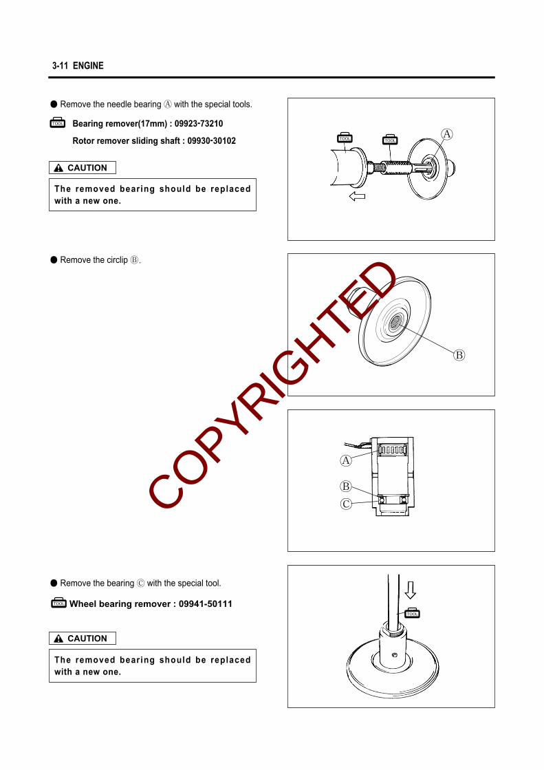
The removed bearing should be replacedwith a new one.
CAUTION
● Remove the needle bearing � with the special tools.
● Remove the circlip �.
● Remove the bearing � with the special tool.
Wheel bearing remover : 09941-50111
The removed bearing should be replacedwith a new one.
CAUTION
Bearing remover(17mm) : 09923-73210
Rotor remover sliding shaft : 09930-30102 �
�
�
�
�COPYRIGHTED

ENGINE 3-12
◉ TRANSMISSION● Drain transmission oil.● Remove the gear box cover ①.● Remove the drive shaft ②.
● Remove the circlip ⑤ and final driven gear ⑥.
● Remove the idle shaft ⑦.
Rotor remover sliding shaft : 09930-30102Bearing remover (12mm) : 09921-20210
● Remove the drive shaft bearing ⑧ and idle shaftbearing.
● Remove the oil seal ③ from the gear box cover withthe special tool.
Oil seal remover : 09913-50121
The removed oil seal should be replaced witha new one.
CAUTION
● Remove the bearing ④ with the special tool.
Bearing installer : 09943-88211
The removed bearing should be replacedwith a new one.
CAUTION
COPYRIGHTED

3-13 ENGINE
Crankcase separater : 09920-13120
● Remove the crankshaft with the special tool.
◉ CRANKCASE● Remove the crankcase securing screws.
Crankcase separater : 09920-13120
NOTE : Loosen the crankcase screws diagonally.
COPYRIGHTED

ENGINE 3-14
● Using two steel tubes of appropriate size, press outthe engine mounting bushings on a vise as shownin the illustration.
● Remove the bushing.
Bushing
COPYRIGHTED

3-15 ENGINE
Front side
Rear side
Bushing
Bushing
Crankcase
Crankcase
COPYRIGHTED

ENGINE 3-16
ENGINE COMPONENTS INSPEC-TION AND SERVICING
BEARINGS
Wash the bearing with cleaning solvent and lubricatewith motor oil before inspecting.Turn the inner ring and check to see that the inner ringturns smoothly. If it does not turn lightly, quietly andsmoothly, or if noise is heard, the bearing is defectiveand must be replaced with a new one.
OIL SEALS
Damage to the lip of the oil seal may result in leakage ofthe fuel-air mixture or oil. Inspect for damage and besure to replace the damaged seal if found.
CRANKSHAFT
◉ CRANKSHAFT RUNOUTSupport the crankshaft by the V-blocks, with the dialgauge rigged to read the runout as shown.
Service limit0.05 mm (0.002 in)
Crankshaft runout
Excessive the crankshaft runout is often responsible forabnormal engine vibration. Such vibration shortensengine life.
◉ WEAR AND CLEARANCE OF CONROD BIG ENDTurn the crankshaft with the conrod to feel the smooth-ness of rotary motion in the big end. Move the rod upand down while holding the crankshaft rigidly to be surethat there is no rattle in the big end.Wear on the big end of the conrod can be estimated bychecking the movement of the small end of the rod. Thismethod can also check the extent of wear on the partsof the conrod s big end.If wear exceeds the limit, conrod, crank pin and crankpin bearing should all be replaced.
V-block : 09943-21304Magnetic stand : 09900-20701Dial gauge : 09900-20606
Service limit3.0 mm (0.12 in)
Conrod big end runout
COPYRIGHTED

3-17 ENGINE
◉ CONROD SMALL END BORE I.D.Measure the conrod small end diameter with a calipergauge.
AUTOMATIC CLUTCH INSPECTION
This vehicle is equipped with an automatic clutch andvariable ratio belt drive transmission. The engagementof the clutch is governed by engine RPMs and centrifu-gal mechanism located in the clutch.To insure proper performance and longevity of theclutch assembly it is essential that the clutch engagessmoothly and gradually. Two inspection checks must beperformed to thoroughly check the operation of the driv-etrain. Follow the procedures listed.
◉ CLUTCH-IN INSPECTIONWarm the engine to normal operating temperature.Connect an engine tachometer to the engine.Seated on the vehicle with the vehicle on level ground,increase the engine RPMs slowly and note the RPM atwhich the vehicle begins to move forward.
◉ CLUTCH TIGHT INSPECTIONGrip the front brake lever and depress rear brake pedalfully, and measure the engine RPM when open thethrottle.Warm the engine to normal operating temperatures.Connect an engine tachometer to the engine.Apply the rear brake as firm as possible.Briefly open the throttle fully and note the maximumengine RPMs sustained during the test cycle.
Dial calipers : 09900-20605
Service limit16.040mm (0.632 in)
Conrod small end bore I.D.
Engine tachometer : 09900-26006
Clutch-in RPMStandardTolerance
3,900 rpm±200 rpmCOPYRIGHTED

ENGINE 3-18
If the engine RPM does not coincide with the specifiedRPM range, then disassemble the clutch.Clutch shoe - inspect the shoes visually for chips,cracking, uneven wear and burning, and check thethickness of the shoes with vernier calipers. If thethickness is less than the following service limit,replace them as a set.Clutch springs - visually inspect the clutch springs forstretched coils or broken coils.
Clutch housing - inspect visually the condition of the innerclutch housing surface for scrolling, cracks, or unevenwear. Measure inside diameter at several points to checkfor an out-of-round condition as well as wear.
Do not apply full power for more than 3 seconds ordamage to the clutch or engine may occur.
CAUTION
Engine tachometer : 09900-26006
Clutch tight RPM5,900 rpm±200 rpm
StandardTolerance
Clutch shoe thicknessService limit
2.0 mm (0.079 in)
Clutch housing I.D.Service limit
112.50 mm (4.429 in)
Clutch shoes or springs must be changed as a setand never individually.
CAUTION
COPYRIGHTED
3-19 ENGINE
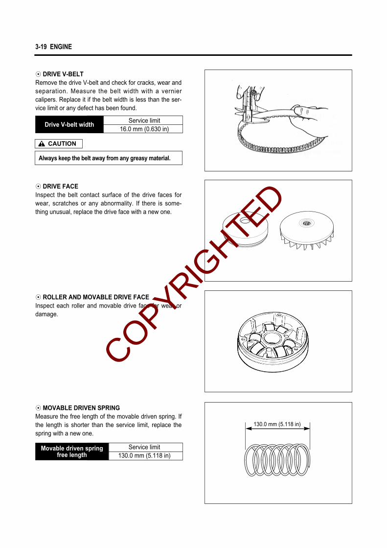
◉ DRIVE V-BELTRemove the drive V-belt and check for cracks, wear andseparation. Measure the belt width with a verniercalipers. Replace it if the belt width is less than the ser-vice limit or any defect has been found.
◉ DRIVE FACEInspect the belt contact surface of the drive faces forwear, scratches or any abnormality. If there is some-thing unusual, replace the drive face with a new one.
◉ ROLLER AND MOVABLE DRIVE FACEInspect each roller and movable drive face for wear ordamage.
◉ MOVABLE DRIVEN SPRINGMeasure the free length of the movable driven spring. Ifthe length is shorter than the service limit, replace thespring with a new one.
Always keep the belt away from any greasy material.
CAUTION
Drive V-belt widthService limit
16.0 mm (0.630 in)
Movable driven springfree length
Service limit130.0 mm (5.118 in)
130.0 mm (5.118 in)
COPYRIGHTED

ENGINE 3-20
Service limit
0.05 mm (0.002 in)
If the largest reading at any portion of the straight-edge exceeds the limit, rework the surface by rubbingit against emery paper (of about #400) laid flat on thesurface plate in a lapping manner. The gasketed sur-face must be smooth and perfectly flat in order tosecure a tight joint : a leaky joint can be the cause ofreduced power output and increased fuel consump-tion.
Cylinder head distortion
◉ DRIVEN FACE PIN AND OIL SEALTurn the driven faces and check to see that the drivenfaces turn smoothly.If any stickness or hitches are found, visually inspectthe lip of seal, driven face sliding surface and slidingpins for wear or damage.
◉ DRIVEN FACE Inspect the belt contacting surface of both driven facesfor any scratches, wear and damage.Replace driven face with new one if there are anyabnormality.
CYLINDER HEADDecarbon the combustion chamber.Check the gasketed surface of the cylinder head fordistortion with a straightedge and thickness gauge,taking a clearance reading at several places.
Thickness gauge : 09900-20806
COPYRIGHTED

3-21 ENGINE
Micrometer(50 ~ 75mm) : 09900-20203
PISTON◉ CYLINDER TO PISTON CLEARANCECylinder-to-piston clearance is the difference betweenpiston diameter and cylinder bore diameter. Be sure totake the maked diameter at right angles to the pistonpin. The value of elevation � is prescribed to be 20mmfrom the skirt end.
CYLINDERDecarbon exhaust port and upper part of the cylinder,taking care not to damage the cylinder wall surface.
The wear of the cylinder wall is determined from diame-ter reading taken at 20mm from the top of the cylinderwith a cylinder gauge. If the wear thus determinedexceeds the limit indicated below, rework the bore to thenext oversize by using a boring machine or replace thecylinder with a new one.
After reworking the bore to an oversize, be sure tochamfer the edges of ports and smooth the chamferededges with emery paper. To chamfer, use a scraper,taking care not to nick the wall surface.
Service limit
52.590 mm (2.071 in)Cylinder bore
Service limit
52.332 mm (2.060 in)Piston diameter
Cylinder gauge set : 09900-20508
COPYRIGHTED

ENGINE 3-22
As a result of the above measurement, if the piston-to-cylinder clearance exceeds the following limit,overhaul the cylinder and use an oversize piston, orreplace both cylinder and piston. The measurementfor the bore diameter should be taken in the intake-to-exhaust port direction and at 20mm from cylindertop surface.
◉ DE-CARBONING De-carbon the piston and piston ring grooves, as illus-trated. After cleaning the grooves, fit the rings androtate them in their respective grooves to be sure thatthey move smoothly.Carbon in groove is liable to cause the piston ring toget stuck in the groove, and this condition will lead toreduce engine power output.A piston whose sliding surface is badly grooved orscuffed due to overheating must be replaced. Shallowgrooves or minor scuff can be removed by grinding withemery paper of about #400.
◉ PISTON PIN BORE I.D.Using a caliper gauge, measure the piston pin boreinside diameter. If reading exceeds the following ser-vice limit, replace it with a new one.
Standard Service limit
Service limit
12.030 mm (0.474 in)Piston pin bore I.D.
Dial calipers : 09900-20605
Cylinder to piston clearance
Piston diameter
Cylinder bore52.500~52.515mm(2.0669~2.0675 in)
52.432~52.447mm(2.0643~2.0648 in)
0.073 ~ 0.083mm(0.0029~0.0033 in)
52.590mm(2.0705 in)
52.332mm(2.0603 in)
0.120mm(0.0047 in)
COPYRIGHTED

3-23 ENGINE
◉ PISTON PIN O.D.Using a micrometer, measure the piston pin outsidediameter at three positions.
Service limit
11.980 mm (0.472 in)Piston pin O.D.
Micrometer(0~25mm) : 09900 - 20201
◉ PISTON RINGSCheck each ring for the clearance, reading the clear-ance with a thickness gauge shown in the illustration. Ifthe clearance is found to exceed the limit, indicatedbelow, replace it with a new one.The clearance of each ring is to be measured with thering fitted squarely into the cylinder bore and held at theleast worn part near the cylinder bottom, as shown inthe illustration.
Service limit
0.75 mm (0.030 in)
Piston ring clearance(Assembly condition)
Service limit
3.6 mm (0.142 in)
Piston ring clearance(Free condition)
Thickness gauge : 09900 - 20806
As the piston ring wears, its clearance increases reduc-ing engine power output because of the resultant blowby through the enlarged clearance. Here lies the impor-tance of using piston rings with the clearance within thelimit.Measure the piston ring free clearance to check thespring tension.
COPYRIGHTED
ENGINE 3-24
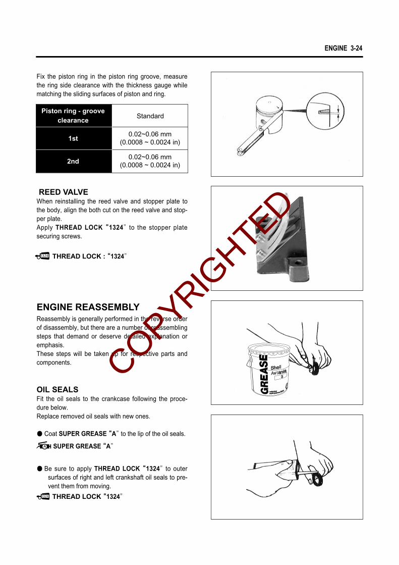
REED VALVEWhen reinstalling the reed valve and stopper plate tothe body, align the both cut on the reed valve and stop-per plate.Apply THREAD LOCK ““1324”to the stopper platesecuring screws.
OIL SEALSFit the oil seals to the crankcase following the proce-dure below.Replace removed oil seals with new ones.
● Coat SUPER GREASE ““A”to the lip of the oil seals.
● Be sure to apply THREAD LOCK ““1324”to outersurfaces of right and left crankshaft oil seals to pre-vent them from moving.
ENGINE REASSEMBLYReassembly is generally performed in the reverse orderof disassembly, but there are a number of reassemblingsteps that demand or deserve detailed explanation oremphasis.These steps will be taken up for respective parts andcomponents.
Fix the piston ring in the piston ring groove, measurethe ring side clearance with the thickness gauge whilematching the sliding surfaces of piston and ring.
0.02~0.06 mm(0.0008 ~ 0.0024 in)
0.02~0.06 mm(0.0008 ~ 0.0024 in)
Standard
THREAD LOCK : ““1324”
THREAD LOCK““1324”
SUPER GREASE““A”
I�nduI�ndu
M�ulti-M�ulti-purpurstrialstrial
posepose G�reaseG�rease
1st
Piston ring - grooveclearance
2nd
COPYRIGHTED
3-25 ENGINE
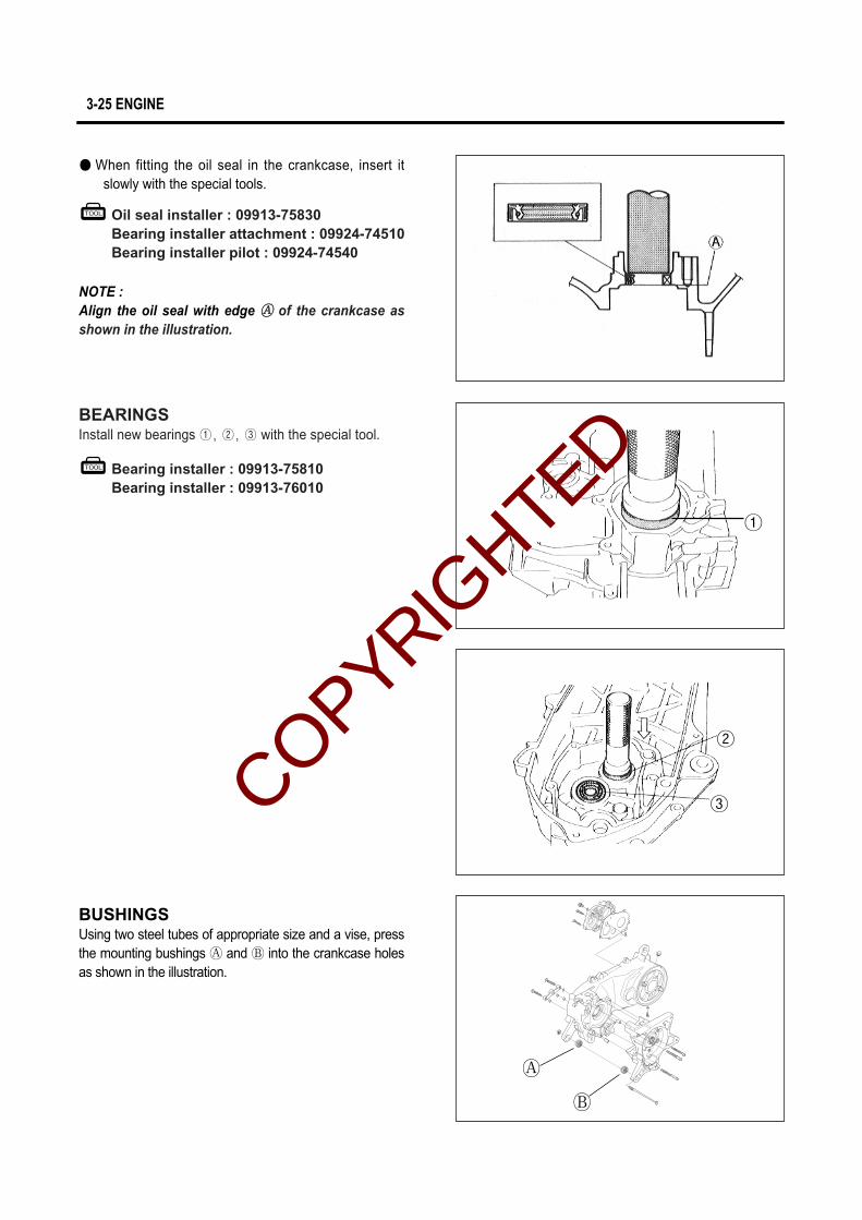
● When fitting the oil seal in the crankcase, insert itslowly with the special tools.
NOTE : Align the oil seal with edge �� of the crankcase asshown in the illustration.
Oil seal installer : 09913-75830Bearing installer attachment : 09924-74510Bearing installer pilot : 09924-74540
Bearing installer : 09913-75810Bearing installer : 09913-76010
BEARINGSInstall new bearings ①, ②, ③ with the special tool.
BUSHINGSUsing two steel tubes of appropriate size and a vise, pressthe mounting bushings � and � into the crankcase holesas shown in the illustration.
②
③
①
�
�
COPYRIGHTED

ENGINE 3-26
CRANKSHAFT
Bushing �Bushing �
Crankcase
Crankcase
Bushing �
NOTE : Knurled end �� should face inside. Protrusive �� and�� should be in the same dimension.
�
�
�
�
�
COPYRIGHTED

3-27 ENGINE
Crankshaft installer : 09900-32812Conrod holder : 09910-20116
Standard
40.0 ± 0.1 mm
(1.575 ± 0.004 in)
Crank web to web width
● Measure the length between the webs referring to thefigure at right when rebuilding the crankshaft.
● When mounting the crankshaft into the crankcase, itis necessary to pull its left end into the crankcasewith the special tool.
Never fit the crankshaft into the crankcase by driv-ing it with a plastic hammer. Always use the specialtool, otherwise crankshaft alignment accuracy willbe affected.
CAUTION
CRANKCASE● Wipe the crankcase mating surfaces (both surfaces)
with cleaning solvent.● Apply BOND “1215”uniformly to the mating surface
of the left half of the crankcase, and install the dowelpins.
● Install the two dowel pins.
● Tighten the crankcase screws securely.● Check if crankshaft rotates smoothly.
BOND “1215” COPYRIGHTED

ENGINE 3-28
NOTE : Align the oil seal with edge �� of the crankcase asshown in the illustration.
Bearing installer : 09913-85210
TRANSMISSION
● Install the new oil seal ① to the crankcase with thespecial tool.
�
1216
COPYRIGHTED

3-29 ENGINE
● Install the circlip ① on to the rear axle shaft ② .● Assemble the idle shaft subassembly using the idle
shaft ③ and thrust washer ④, then install the sub-assembly on the gear box.
● Install the final driven gear ⑤ on the rear axle shaftusing the circlip ⑥.
④
③
Thrust�
Rounded coner
Circlip
Center
● Install the idle thrust washer ⑦, new gasket anddowel pin ⑧.
● Install the driveshaft ⑨ to the gear box cover.
● Install the gear box cover ⑩ on the crankcase.
● Tighten all the screws evenly one by one in a diago-nal fashion.
COPYRIGHTED

ENGINE 3-30
STARTER PINION, STARTER DRIVEN GEAR AND STARTER MOTOR
● Apply SUPER GREASE“A”on the pinion shaft andinstall the starter pinion subassembly.
● Assemble the starter pinion subassembly ①.
● Insert the two dowel pins ② on the crankcase.
SUPER GREASE“A”
COPYRIGHTED

3-31 ENGINE
● Install the new O-ring ③.
● Install the starter motor ④.
● Install the starter driven gear ② over the leftcrankshaft end.
NOTE : The convex side of hub should face outside wheninstalled in proper position.
● Install the starter idle gear cap ①.
COPYRIGHTED
ENGINE 3-32
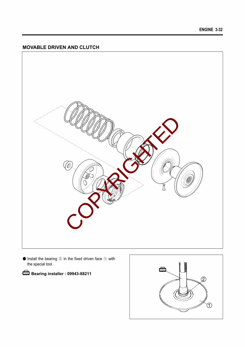
Bearing installer : 09943-88211
● Install the bearing ② in the fixed driven face ① withthe special tool.
MOVABLE DRIVEN AND CLUTCH
COPYRIGHTED

3-33 ENGINE
● Install the circlip ①.
Insert surely in the circlip groove.
CAUTION
Bearing installer : 09943-88211
● Install the bearing ② with the special tool.
Bearing installer : 09913-76010
● Install the new O-rings (④, ⑤) to the movable drivenface ③ with the special tool.
● Apply SUPER GREASE “A”to the groove of mov-able driven face’s inside.
A mark part of the bearing is pointed to the outside.
CAUTION
Thrust�
Rounded coner
SUPER GREASE“A”
COPYRIGHTED

ENGINE 3-34
● Install the movable driven face seat ⑤.
The seat is installed rotatable naturally.The O-ring get damaged, in case of installed byforce.
CAUTION
● Install the spacer and pin ③ at three places on thedriven face hub.
● Apply SUPER GREASE “A”lightly to the cam partwhere the pins are placed.
● Position the two O-rings ④.
Pin
Spacer
SUPER GREASE“A”
● Install the movable driven face ① to the fixed drivenface ②.
When reinstalling the movable driven face to thefixed driven face, make sure that the O-ring ispositioned properly.
CAUTION Insert as guide the rim.
COPYRIGHTED

3-35 ENGINE
Rotor holder : 09930-40113
Clutch shoe nut : 40~60 N∙∙m (4.0~6.0 kg∙∙m)
● Install the spring ①.● Install the clutch shoe assembly ② and nut ③.
● Tighten the nut to the specified torque with the spe-cial tool.
Clutch housing nut : 40~60 N∙∙m (4.0~6.0 kg∙∙m)
● Thoroughly clean the clutch housing ④ to be freefrom oil and position it over the clutch shoe assem-bly.
● Tighten the clutch housing nut ⑤ to the specifiedtorque.
● Insert the V-belt between the driven faces as deepinside as possible while pulling the movable drivenface all the way outside to provide the maximum beltclearance.
The V-belt should be positioned so that thearrows on the belt periphery point the normalturning direction. The V-belt contact face on thedriven faces should be thoroughly cleaned to befree from oil.
CAUTION
COPYRIGHTED

ENGINE 3-36
● Install the roller ② at six places to the movable driveface ①.
● Mount the three dampers ④ on the movable driveplate ③ and install it on the movable drive face ⑤ .
● Position the O-ring ⑥ on the movable drive face.
MOVABLE DRIVE
COPYRIGHTED

3-37 ENGINE
Conrod holder : 09910-20115
Fixed drive face nut: 40~60 N∙∙m (4.0~6.0 kg∙∙m)
● Install the movable drive face cover ①.
● Position the movable drive face subassembly on thecrankshaft as shown in the photo.
● Insert the spacer ②.
● Install the fixed drive face ③ .● Tighten the fixed drive face nut ④ to the specified
torque with the special tool.
● Continue turning the fixed drive face ⑤ by hand untilthe V-belt is seated in and both the drive and drivenfaces ⑥ will move together smoothly without slip.
● Fill the final gear box with transmission oil up to thelevel hole.
● Tighten the oil level bolt ⑦ to the specified torque.
Make sure that the movable drive plate is fullypositioned inside, or the weight roller may comeoff.
CAUTION
Thoroughly clean the V-belt contact face to befrom oil.
CAUTION
Replace
Overhaul
80 ㎖
90 ㎖
Transmission oil capacity
Transmission oil level bolt: 4~7 N∙∙m (0.4~0.7 kg∙∙m)
COPYRIGHTED

ENGINE 3-38
THREAD LOCK “1324”
Conrod holder : 09910-20115
Magneto rotor nut: 35~45 N∙m (3.5~4.5 kg∙m)
● Install the rotor ③ .
● Apply THREAD LOCK““1324””to the rotor nut ④ andtighten it to the specified torque with the special tool.
● Degrease the tapered portion of the crankshaft andalso the magneto rotor.
● Install the stator ①.
● Install the key ②.
MAGNETO
COPYRIGHTED

Position the ring so that the marking is on upside.
CAUTION
3-39 ENGINE
● Install the piston ring on the piston.∙ 1st ∙ 2nd
● It is extremely important that, when the piston is fedinto the cylinder, each ring in place should be sopositioned as to hug the locating pin as shown in theillustration.
7
PISTON
Locating pin
Position the ring so that the marking is on upside.
CORRECT INCORRECT
] Keystone ring
COPYRIGHTED

ENGINE 3-40
● Apply engine oil on the piston pin and install the pis-ton to the conrod.
● The circlip should be mounted in such a position thatthe mating ends of the circlip do not coincide with thegroove portion of the piston.
● Position the cylinder base gasket.● Apply engine oil on the piston and cylinder wall sur-
faces and install the cylinder over the piston carefully.● Install the cylinder head gasket and cylinder head.
● Tighten the cylinder head nut to the specification, andtighten it diagonally several times as shown in theillustration.
The arrow mark �� on the piston head shouldpoint the exhaust side.
CAUTION
Cylinder head nut: 18~28 N∙∙m (1.8~2.8 kg∙∙m)
OutsideInside
�
COPYRIGHTED
3-41 ENGINE
SUPER GREASE “A”
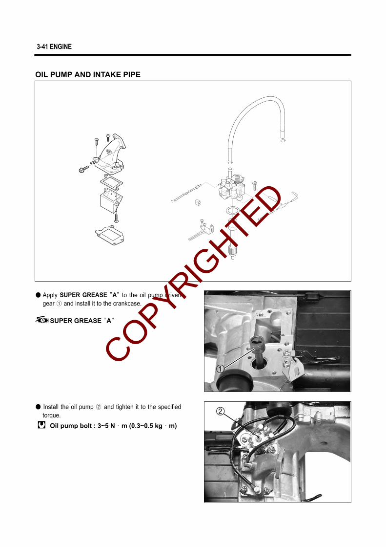
● Apply SUPER GREASE ““A””to the oil pump drivengear ① and install it to the crankcase.
Oil pump bolt : 3~5 N∙m (0.3~0.5 kg∙m)
● Install the oil pump ② and tighten it to the specifiedtorque.
OIL PUMP AND INTAKE PIPE
COPYRIGHTED

ENGINE 3-42
● Install the reed valve gasket ①, intake pipe gasket ②and intake pipe ④ with reed valve ③ to thecrankcase.
● Install the fan case ⑥.
● Install the magneto lead wire and starter motorlead wire.
COOLING FAN● Install the cylinder cowling ⑤.
COPYRIGHTED
3-43 ENGINE
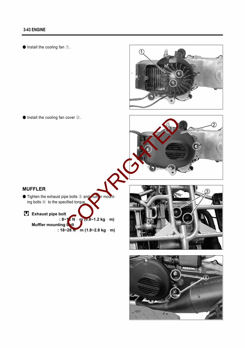
● Install the cooling fan cover ②.
Exhaust pipe bolt : 8~12 N∙m (0.8~1.2 kg∙m)
Muffler mounting bolt : 18~28 N∙m (1.8~2.8 kg∙m)
● Tighten the exhaust pipe bolts ③ and muffler mount-ing bolts ④ to the specified torque.
MUFFLER
● Install the cooling fan ①.
COPYRIGHTED

FUEL SYSTEM 4-44
FFUUEELL SSYYSSTTEEMM
4
CARBURETOR 4- 1
REMOVAL 4- 1
DISASSEMBLY 4- 2
INSPECTION 4- 4
REASSEMBLY AND REMOUNTING 4- 5
FUEL TANK 4- 7
REMOVAL 4- 7
INSPECTION 4- 7
REMOUNTING 4- 8
OIL PUMP 4- 8
CONTENTS
COPYRIGHTED

4-1 FUEL SYSTEM
REMOVAL
● Remove the front and rear fender.
CARBURETOR
COPYRIGHTED
FUEL SYSTEM 4-2
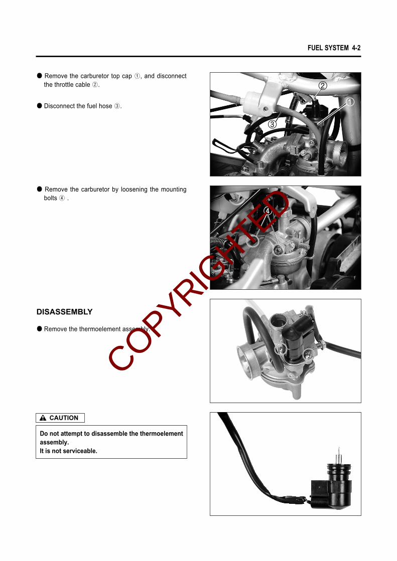
● Remove the carburetor top cap ①, and disconnectthe throttle cable ②.
● Disconnect the fuel hose ③.
● Remove the carburetor by loosening the mountingbolts ④ .
● Remove the thermoelement assembly.
DISASSEMBLY
Do not attempt to disassemble the thermoelementassembly.It is not serviceable.
CAUTION
COPYRIGHTED

4-3 FUEL SYSTEM
● Remove the float chamber ①.
● Pull out the float pin ② and remove the float ③.
● Remove the needle valve ④.
● Remove the throttle valve, spring and jet needle.
COPYRIGHTED

FUEL SYSTEM 4-4
● Remove the pilot jet ③, main jet ④ and needle jet⑤.
● Remove the throttle stop screw ① and pilot airscrew ② .
When removing the pilot air screw, record therevolutions until tighten completly.
CAUTION
Inspect the valve surface for worn
Foreign matter
◉◉ NEEDLE VALVE INSPECTIONIf foreign matter is caught between the valve seat andthe needle, the gasoline will continue flowing and causeit to overflow. If the seat and needle are worn beyond thepermissible limits, similar trouble will occur. Conversely,if the needle sticks, the gasoline will not float chamber.Clean the float chamber and float parts with gasoline. Ifthe needle is worn as shown in the illustration, replace ittogether with a valve seat. Clean the fuel passage of themixing chamber with compressed air.
INSPECTIONCheck following items for any damage or clogging.● Pilot jet● Main jet● Pilot air screw● Needle jet air bleeding hole● Float● Gasket● Pilot outlet and bypass holes
①
④
⑤③
②
,
COPYRIGHTED

4-5 FUEL SYSTEM
REASSEMBLY AND REMOUNTING● Reassemble following items.
① Pilot air screw② Throttle stop screw③ Pilot jet④ Main jet⑤ Needle jet
● Install the needle valve ⑥ and float ⑦ on the carbu-retor body.
● Insert the float pin ⑧ to the carburetor.● Install the gasket and float chamber.
● Install the throttle valve, spring and jet needle.
COPYRIGHTED
FUEL SYSTEM 4-6
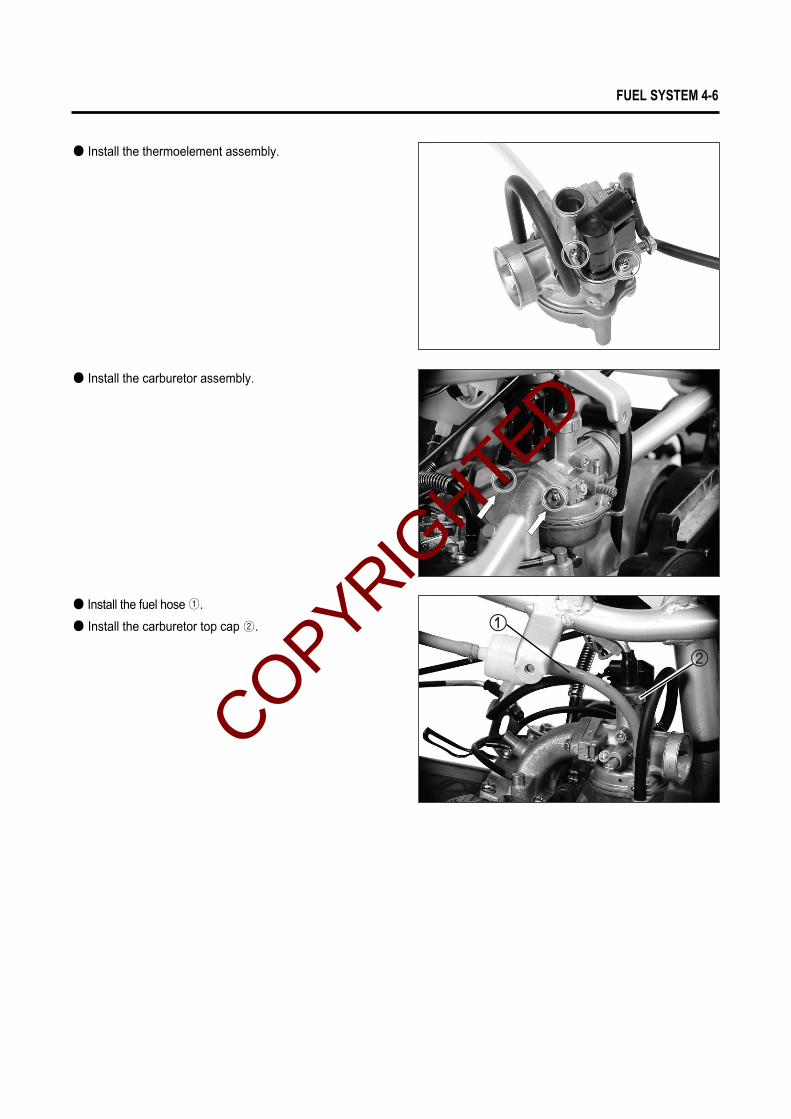
● Install the carburetor top cap ②.
● Install the carburetor assembly.
● Install the fuel hose ①.
● Install the thermoelement assembly.
COPYRIGHTED
4-7 FUEL SYSTEM
FUEL TANK
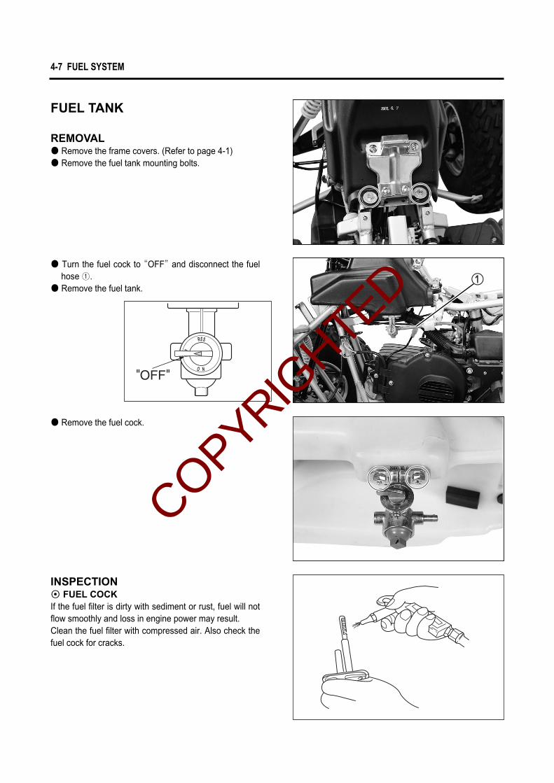
REMOVAL● Remove the frame covers. (Refer to page 4-1)● Remove the fuel tank mounting bolts.
● Turn the fuel cock to “OFF”and disconnect the fuelhose ①.
● Remove the fuel tank.
● Remove the fuel cock.
INSPECTION◉◉ FUEL COCKIf the fuel filter is dirty with sediment or rust, fuel will notflow smoothly and loss in engine power may result.Clean the fuel filter with compressed air. Also check thefuel cock for cracks.
COPYRIGHTED

FUEL SYSTEM 4-8
REMOUNTINGRemount the fuel tank and fuel cock in the reverse orderof removal.
OIL PUMP
◉◉ AIR BLEEDINGWhenever evidence is noted of some air having leakedinto the oil pipe from the oil tank in a machine brought infor servicing, or if the oil pump has to be removed forservicing, be sure to carry out an air bleeding operatingwith the oil pump in place before returning the vehicle tothe user. To bleed air, hold the vehicle in standstill condition.Loosen the air bleeding screw ① to let out air and aftermaking sure that the trapped air has all been bled, tight-en the air bleeding screw completely.
� Gaskets ① and ② must be replaced with new ones to prevent fuel leakage.
� Tighten the fuel cock bolts evenly.
WARNING
During this inspection, strictly follow the follow-ing points.�� Do not touch the rear wheel while running the
engine.
CAUTION
HYPOL Oil gauge : 09900-21602
◉◉ CHECKING OIL PUMPUse the special tool, to check the pump for capacity bymeasuring the amount of oil the pump draws during thespecified interval.● Remove the frame cover.● Have the HYPOL Oil gauge filled with HYOSUNG
HYPOL OIL HS and connect it to the suction side ofthe pump.
● Run the engine at 3,000 rpm.● Holding engine speed at the same 3,000 rpm, let the
pump draw for 5 minutes. For this operation, thereading taken on the device should be 2.6 ~ 2.8㎖..
2.6 ~ 2.8㎖.(at 3,000 rpm for 5 minutes)
Engine oil discharge amount
COPYRIGHTED

COPYRIGHTED
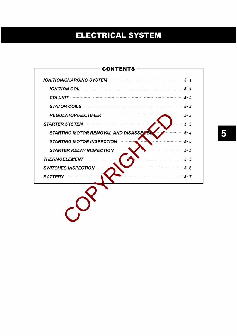
IGNITION/CHARGING SYSTEM 5- 1
IGNITION COIL 5- 1
CDI UNIT 5- 2
STATOR COILS 5- 2
REGULATOR/RECTIFIER 5- 3
STARTER SYSTEM 5- 3
STARTING MOTOR REMOVAL AND DISASSEMBLY 5- 4
STARTING MOTOR INSPECTION 5- 4
STARTER RELAY INSPECTION 5- 5
THERMOELEMENT 5- 5
SWITCHES INSPECTION 5- 6
BATTERY 5- 7
ELECTRICAL SYSTEM
5
CCOONNTTEENNTTSS
COPYRIGHTED

W/L
Ground
Plug cap
Pocket tester : 09900-25002
● Check the ignition coil with the pocket tester.
Primary
Secondary
0.19 ~ 0.24 Ϊ
5.4 ~ 6.6 ㏀
Ignition coil resistance
5-1 ELECTRICAL SYSTEM
lgnitioncoil
Spark plug
Engine stopswitch
CDIunit
Stator
RegulatorRectifier Battery
12V 4AH(MF)
IGNITION/CHARGING SYSTEM
Over 8 mm (0.3 in)Spark performance
IGNITION COIL● Pull out the spark plug.● Place it on the cylinder head after installing it at the
plug cap to obtain ground.● Push in the electric starter switch to rotate the start-
ing motor, test sparking performance.
COPYRIGHTED

ELECTRICAL SYSTEM 5-2
Stator coil resistance Standard
Lighting coil
Charging coil
Exciting coil
Pick-up coil
Y/W - Ground
W/R - Ground
B/R - Ground
Br - W
STATOR COILS● Using the pocket tester, measure the resistance
between the lead wire and ground. If the resistancechecked is incorrect, replace the coil.
CDI UNITUsing the pocket tester (R × 1㏀ range), measure theresistance between the lead wires in the followingtable.
Unit :Ϊ
When making this test, be sure that the battery isin fully-charged condition.
CAUTION
◉◉ CHARGING OUTPUT CHECKStart the engine and keep it running at 5,000 rpm.Measure the DC voltage between the battery terminal �and � with a pocket tester.If the tester reads under or over following specification,check the no-load performance or replace the regula-tor/rectifier.
Pocket tester : 09900-25002Engine tachometer : 09900-26006
13.0 ~ 16.0 V (at 5,000 rpm)Standard charging output
Pocket tester : 09900-25002
�P
robe
ofte
ster
� Probe of tester
1 2 3 4 5 6
1
2
3
4
5
6
Unit : ㏀
14~18
3.6~4.4
8~10
12.5~15.5
10.5~13.5
OFF OFF OFF OFF
OFF OFF
7~9 3~4 7.5~9.5 5.5~6.5
3~4 3~4 2~2.5
6~8 27~33 29~35
5~7 2~2.5 6~7
OFF OFF OFF
OFF
OFF
OFF
0.54 ~ 0.80 Ϊ
0.69 ~ 1.30 Ϊ
146 ~ 220 Ϊ
90 ~ 110 Ϊ
COPYRIGHTED
5-3 ELECTRICAL SYSTEM
Starter relay
IG switch Starter switch
Y/G
R
Fuse
Brake switch
BatteryB/W
Point
R/W
Startermotor
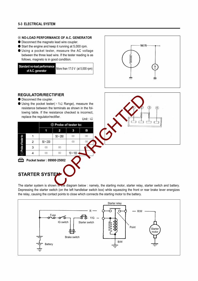
More than 17.0 V (at 5,000 rpm)Standard no-load performance
of A.C. generator
◉◉ NO-LOAD PERFORMANCE OF A.C. GENERATOR● Disconnect the magneto lead wire coupler.● Start the engine and keep it running at 5,000 rpm.● Using a pocket tester, measure the AC voltage
between the three lead wire. If the tester reading is asfollows, magneto is in good condition.
Pocket tester : 09900-25002
REGULATOR/RECTIFIER● Disconnect the coupler.● Using the pocket tester(×1㏀ Range), measure the
resistance between the terminals as shown in the fol-lowing table. If the resistance checked is incorrect,replace the regulator/rectifier.
�Pr
obeo
fteste
rto:
�� Probe of tester to:
1 2 3 4
1 2 3 B
50 ~ 230
∞ ∞
∞∞
∞∞∞
∞ ∞
50 ~ 260
10 ~ 100
1
2
3
4
STARTER SYSTEM
The starter system is shown in the diagram below : namely, the starting motor, starter relay, starter switch and battery.Depressing the starter switch (on the left handlebar switch box) while squeezing the front or rear brake lever energizesthe relay, causing the contact points to close which connects the starting motor to the battery.
Unit : ㏀
COPYRIGHTED

ELECTRICAL SYSTEM 5-4
Segment
①
STARTING MOTOR REMOVAL AND DISASSEMBLYRemove the starting motor.Disassemble the starting motor as shown in the illustration.
Service limit
3.5 mm (0.138 in)Carbon brushes wear
Service limit
0.2 mm (0.008 in)Commutator under cut
STARTING MOTOR INSPECTION◉◉ CARBON BRUSHESWhen the brushes are worn, the motor will be unable toprocedure sufficient torque, and the engine will be diffi-cult to turn over. To prevent this, periodically inspect thelength of the brushes and replace them when they aretoo short or chipping.
◉◉ COMMUTATORIf the commutator surface is dirty, starting performancewill decrease. Polish the commutator with #400 or simi-lar fine emery paper when it is dirty. After polishing wipethe commutator with a clean dry cloth.Measure the commutator under cut ①.
COPYRIGHTED

BattaryPTC Regurator/Rectifier
W/R
W/R
R
B/W
B/W
W/R
R B/W
Y/WY/W
� �
THERMOELEMENT
5-5 ELECTRICAL SYSTEM
Pocket tester : 09900-25002
Pocket tester : 09900-25002
◉◉ ARMATURE COILUsing the pocket tester, check the coil for open andground by placing probe pins on each commutator seg-ment and rotor core (to test for ground) and on any twosegments at various places (to test for open), with thebrushes lifted off the commutator surface.If the coil is found to be open-circuited or grounded,replace the armature. Continuous use of a defectivearmature will cause the starting motor to suddenly fail.
STARTER RELAY INSPECTION● Disconnect the starter relay lead wire coupler.
Check the coil for “open”, “ground”and ohmic resis-tance. The coil is in good condition, if the resistanceis as follows.
Standard
80 ~ 150 ΪStarter relay standard resistance
COPYRIGHTED

ELECTRICAL SYSTEM 5-6
W/B
○ ○
Y/G
ON
OFF
This check should be carried out when the carbu-retor is cold.
CAUTION
◉◉ INSPECTION● Disconnect the thermoelement coupler ①.● Connect the thermoelement coupler ① to a 12V bat-
tery and touch the thermoelement ② to check thetemperature being raised.The thermoelement ② should become heated to atemperature more than that of human body withinfive minutes. If not, replace with new one.
Pocket tester : 09900-25002
SWITCHES INSPECTION
Inspect each switch for continuity with the pocket testerreferring to the chart. If it is found any abnormality,replace the respective switch assembly with new one.
STARTER SWITCH
B/W B/R R O
OFF
ON
○ ○
○ ○
WIRE COLORB BlackL BlueG GreenGr GraySb Light blueLg Light greenO OrangeR RedW WhiteY YellowB/R Black with Red tracerB/W Black with White tracerW/B White with Black tracerY/W Yellow with White tracerY/G Yellow with Green tracerL/W Blue with White tracer
IGNITION SWITCH
B/R
○ ○
B/W
ENGINE STOP SWITCH
COPYRIGHTED

5-7 ELECTRICAL SYSTEM
BATTERY
◉ CAUTION OF BATTERY TREATMENTThe battery should be well taken care of because it emits flammable gas.If you don’t follow the instruction in the below, there may be a explosion and severe accident.Therefore, please pay attention to the following points.
● Prohibit positively battery from contacting to short, spark or firearms.● The recharge of battery should be done in the wide place where the wind is well ventilated.
Please don’t recharge it at the sight of wind-proof.
◉ CAUTION OF BATTERY ELECTROLYTE TREATMENT● Pay attention for the battery electrolyte not to stain the chasis or the humanbody. ● If it stain the chassis or the humanbody, at once wash a vast quantity of water.
When it is stained, clothes should come into being a hole or painting should take off.Consult you with a doctor.
● When the battery electrolyte was dropped to the surface of land, wash a vast quantity of water.Neutralize by hydroxide, bicarbonate of soda and so on.
◉ CAUTION OF MAINTENANCE FREE BATTERY TREATMENT
● Do not remove the aluminum tape to seal the battery electrolyte filler hole untill use as battery of completely seal type.
● Do not use it except the battery electrolyte.● When pour into the battery electrolyte, necessarily
use the electrolyte of the specified capacity.● Do not open the sealing cap after recharge the bat-
tery eletrolyte.
● Filling electrolyte.① The battery is put on even land, remove the alu-
minum tape sealing.② Remove the cap at the electrolyte container.
Do not remove the seal, not prick with sharp thing.
CAUTION Aluminum tape
Filler holes
COPYRIGHTED

SealCap
Air bubble
ELECTRICAL SYSTEM 5-8
③ Pouring of battery electrolyteWhen insert the nozzles of the electrolyte container intothe battery’s electrolyte filler holes, holding the containerfirmly so that it does not fall.Take precaution not to allow any of the fluid to spill.
There may be a case which can’’t pour the elec-trolyte if you put it into electrolyte container slopely.
CAUTION
④ Confirmation of pourMake sure that air bubbles are coming up each elec-trolyte container, and keep this position for about more than 20 minutes.
If no air bubbles are coming up from a filler port, tap the bottom of the two or three times.
CAUTION
COPYRIGHTED

Insert the caps firmly
5-9 ELECTRICAL SYSTEM
⑤ Separation of electrolyte containerAfter confirming that you entered the electrolyte into bat-tery completely, remove the electrolyte containers from the battery.
Draw the empty receptacle out slowly because there may be a chance which remaining elec-trolyte vaporize.
CAUTION
⑥ Insert of the capsInsert the cap into the filler holes, pressing it firmly so that the top of the caps do not protrude above the upper surface of the battery’s top cover.
◉ ASSISTANCE RECHARGINGUse the battery that is made after 2 years as the main-tenance free battery.Use the battery at condition of the high temperature.Assistance recharging to the following points.● The main principle of assistance recharging.
Assistence recharging from rule of electric current or voltage, when the battery discharged.
● Do not assistance recharge except the right side table.
● In times of recharging the battery, please do it at the condition of removal of the lead wire.
The firearm is strictly prohibited.
WARNING
Assistance Recharging
Standard
Fast
0.5A × 5 hours
5A × 30 minutes.
COPYRIGHTED

CHASSIS
FRONT WHEEL AND BRAKE 6- 1
REMOVAL 6- 2
INSPECTION AND DISASSEMBLY 6- 3
REASSEMBLY AND REMOUNTING 6- 4
STEERING AND FRONT SUSPENSION 6- 6
REMOVAL AND DISASSEMBLY 6- 6
INSPECTION 6- 9
REASSEMBLY AND REMOUNTING 6-10
TOE-IN ADJUSTMENT 6-11
REAR WHEEL 6-12
REMOVAL 6-12
INSPECTION 6-12
REMOUNTING 6-12
REAR BRAKE 6-13
BRAKE PAD REPLACEMENT 6-13
CALIPER DISASSEMBLY 6-13
DISC PLATE INSPECTION 6-14
CALIPER REASSEMBLY 6-14
REAR AXLE HOUSING, AXLE SHAFT AND SHOCK ABSORBER 6-15
REMOVAL 6-15
INSPECTION AND DISASSEMBLY 6-16
REASSEMBLY AND REMOUNTING 6-18
CCOONNTTEENNTTSS
6
COPYRIGHTED
6-1 CHASSIS
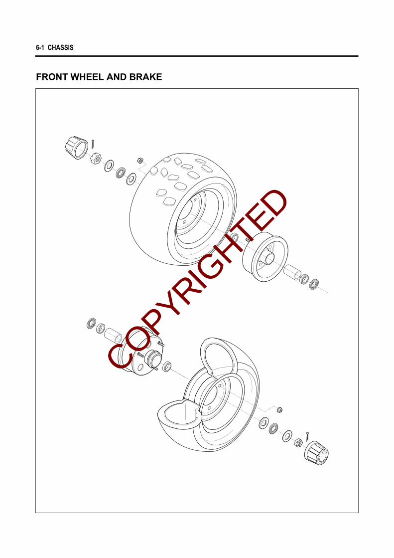
FRONT WHEEL AND BRAKE
COPYRIGHTED
CHASSIS 6-2
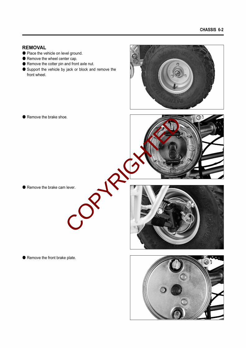
● Remove the brake shoe.
● Remove the brake cam lever.
● Remove the front brake plate.
REMOVAL ● Place the vehicle on level ground.● Remove the wheel center cap.● Remove the cotter pin and front axle nut.● Support the vehicle by jack or block and remove the
front wheel.
COPYRIGHTED

6-3 CHASSIS
● Remove the spacer.● Remove the inner and outer dust seals with the spe-
cial tool.
The removed dust seal should be replaced withnew ones.
CAUTION
INSPECTION AND DISASSEMBLY
◉◉ WHEEL HUB BEARINGInspect the play of bearing inner ring by hand whilemounted in the wheel hub.Rotate the inner ring by hand to inspect if any abnormalnoise occurs or it rotates smoothly.Replace the bearing if there is anything unusual.
◉◉ BRAKE DRUMMeasure the brake drum I.D. to determine the extent ofwear and, if the limit is exceeded by the wear noted,replace the brake drum.The value of this limit is indicated inside of drum.
Oil seal remover : 09913-50121
● Drive out the both bearings with the special tool in thefollowing procedures.
● Insert the adapter into the bearing.● After inserting the wedge bar from the opposite side,
lock the wedge bar in the slit of the adapter.● Drive out the bearing by knocking the wedge bar.
Wheel bearing remover : 09941-50111
The removed bearing should be replaced with new one.
CAUTION
◉◉ TIRE : Refer to page 2-11
Brake drum I.D.Service limit
110.7 mm (4.358 in)
COPYRIGHTED

CHASSIS 6-4
◉◉ BRAKE SHOECheck the brake shoe and decide whether it should bereplaced or not from the thickness of brake lining.
REASSEMBLY AND REMOUNTINGReassemble and remount the front wheel and brake inthe reverse order of removal and disassembly, and alsocarry out the following steps :● When installing the brake camshaft, apply SUPER
GREASE “A”to the camshaft and cam face.
● Install the brake shoes with spring hooks faced inside.
● Install the brake cam lever to the brake camshaft.●Tighten the brake cam lever nut to the specified
torque.
SUPER GREASE“A”
Be careful not to apply too much grease to thecam and pin. If grease gets on the lining, breakslippage will result.
CAUTION
Replace the brake shoe as a set, otherwise brak-ing performance will be adversely affected.
CAUTION
Front brake cam lever nut: 6~8 N∙∙m (0.6~0.8 kg∙∙m)
Brake shoe liningthickness
Service limit
2 mm (0.079 in)
COPYRIGHTED

6-5 CHASSIS
BOND “1215”
● Apply BOND “1215”to the front brake plate asshown photo.
● Install the front brake drum and tire.
COPYRIGHTED

CHASSIS 6-6
STEERING AND FRONT SUSPENSION
REMOVAL AND DISASSEMBLY● Remove the front fender. ● Remove the front wheel and brake. (Refer to page 6-2)● Remove the tie-rod end nut.● Remove the steering knuckle.
TIGHTENING TORQUE
ITEM N∙∙m
18 ~ 28
18.4 ~ 28.6 1.84 ~ 2.86
22.4 ~ 35.7
40 ~ 50
80 ~ 100
22 ~ 35
22 ~ 35
40 ~ 60
� : ASSEMBLING APPLY GREASE� : ASSEMBLING APPLY GREASE� : APPLY GREASE TO LIPS � : APPLY GREASE� : ASSEMBLING APPLY GREASE
1.8 ~ 2.8
2.24 ~ 3.57
4.0 ~ 5.0
8.0 ~ 10.0
2.2 ~ 3.5
2.2 ~ 3.5
4.0 ~ 6.0
kg∙∙m
①
②
③
④
⑤
⑥
⑦
⑧
①
③
④
⑤
⑤
⑧ ⑦
⑧ ⑦
④
②
⑥
⑥
�
�
�
�
�
�
�
COPYRIGHTED

6-7 CHASSIS
● Remove the suspension arm mounting bolts and frontshock absorber upper mounting bolt.
● Remove the suspension arm with shock absorber.
● Remove the shock absorber.
● Remove the dust seals and spacer.
COPYRIGHTED

CHASSIS 6-8
● Remove the handlebar switch.● Remove the throttle lever case.● Remove the front brake lever holder.
● Remove the front brake cables.
● Remove the steering head cover bracket and handle-bar by removing the mounting bolts.
● Remove the tie-rods by removing the cotter pins andnuts.
● Remove the cotter pin and steering shaft lower nut.
The removed cotter pins should be replaced withnew ones.
CAUTION
COPYRIGHTED

6-9 CHASSIS
INSPECTIONInspect the removed parts for the following abnormali-ties.� Handlebar distortion� Handlebar clamp wear
①
◉◉DUST SEALInspect the dust seals for damage.
◉◉TIE-RODInspect the tie-rod for distortion and the boot for wear.
◉◉STEERING SHAFT AND HOLDERlnspect the steering shaft for distortion or bend.
lnspect the two steering shaft holders for wear.
● Separate the tie-rod ends ①, nuts ②, ③ and steeringtie-rods ④.
● Remove the cotter pins ⑤, and remove the steeringshaft holder bolts ⑥ .
● Remove the steering shaft holders and steering shaft .
Inside lock nuts ②② are left-hand thread.
CAUTION
⑤ ⑥
① ②④
③①
Tire side
COPYRIGHTED

CHASSIS 6-10
◉◉SHOCK ABSORBERlnspect the shock absorber for oil leakage or other dam-age.
REASSEMBLY AND REMOUNTINGReassemble and remount the steering system in thereverse order of removal and disassembly, and alsocarry out the following steps :● Align the mating face of front brake holder with the
respective punch mark and tighten the bolt.
◉◉TIE ROD● Install the tie-rod ends ①, nuts ②, ③ and steering tie-
rods ④.
Inside lock nuts ②② are left-hand thread.
CAUTION
◉◉ HANDLEBAR● Install the handlebar with the punch mark aligned with
the handlebar holder as shown.● Tighten the handlebar holder bolts to the specified
torque.
NOTE :The gap ⑤ between the handlebar holder shouldbe even.
Handlebar holder bolt : 18.4~28.6 Nㆍㆍm (1.84~2.86 kgㆍㆍm)
⑤ ⑤
① ②④
③
①
Tire side
COPYRIGHTED

6-11 CHASSIS
③
TOE-IN ADJUSTMENTThe procedure for adjusting the toe-in as follows. ● Place the vehicle on level ground and set the handle-
bar straight.Make sure that all tires are inflated to the standardpressure.
● Loosen the lock nuts ① on each tie-rod.
● Measure the distances A and B of front wheels (inillustration) and adjust the tie-rods, right and left, towithin the specified range.
kPa
25
25
kgf/㎠
0.25
0.25
psi
3.6
3.6
Front
Rear
COLD INFLATION TIRE PRESSURE
Inside lock nuts ① are left-hand thread.
CAUTION
NOTE : A - B = Toe-in
Toe - in 8 mm (0.315 in)
● Temporarily tighten the four lock nuts.● Check that the distances C and D ( in the illustration )
are equal. If the distances C and D are not equal,readjust the tie-rod, right or left, whichever makes thetoe-in value closer to the specification. Check the toe-in again by measuring the distances A and B.
● If the toe-in is not within specification, repeat theadjustment as above until proper toe-in value isobtained and at the same time the distances C and Dbecome equal.
● Tighten the four nuts ① after adjustment of toe-in ismade.
Tie-rod lock nut : 22.4~35.7 Nㆍㆍm (2.24~3.57 kgㆍㆍm) 90�
①
Tire side
� FRONT
COPYRIGHTED

CHASSIS 6-12
REAR WHEEL
REMOVAL ● Place the vehicle on level ground.● Support the vehicle by jack or block.● Romove the wheel center cap.● Romove the cotter pin and rear hub nut.
INSPECTION◉◉ TIRE : Refer to page 2-11
REMOUNTINGRemount the rear wheel in the reverse order of removal.
TIGHTENING TORQUE
ITEM N∙∙m
60 ~ 90
20 ~ 30 2.0 ~ 3.0
22 ~ 35
22 ~ 35
120 ~ 150
6.0 ~ 9.0
2.2 ~ 3.5
2.2 ~ 3.5
12.0 ~ 15.0
kg∙∙m
①
②
③
④
⑤
� : ASSEMBLING APPLY GREASE� : ASSEMBLING APPLY LOCK TIGHT
①②
③
④
②
①
⑤
�
�
�
COPYRIGHTED

6-13 CHASSIS
REAR BRAKE
BRAKE PAD REPLACEMENT● For replacing procedure of brake pad : Refer to page
2-9
CALIPER DISASSEMBLY● Remove the brake lever bolt ① and caliper mounting
bolts ②.● Remove the caliper.● Remove the brake pad. (Refer to page 2-9 )
TIGHTENING TORQUE
ITEM N∙∙m
2 ~ 4
6 ~ 8 0.6 ~ 0.8
0.2 ~ 0.4
kg∙∙m
①
②
①
�
②
� : ASSEMBLING APPLY GREASECOPYRIGHTED

CHASSIS 6-14
DISC PLATE INSPECTION● Check the disc for wear with a micrometer. Replace
the disc if the thickness exceeds the service limit.
Dial gauge : 09900-20606Magnetic stand : 09900-20701
CALIPER REASSEMBLYReassemble and remount the caliper in the reverseorder of removal and disassembly, and also carry out thefollowing steps.● Tighten the brake lever bolt ① and caliper mounting
bolts ② to the specified torque.
● Check the disc for face runout with a dial gauge asshown. Replace the disc if the runout exceeds theservice limit
● Remove the rear caliper lever return spring .
Micrometer(0~25mm) : 09900-20201
Disc thicknessService limit
2.5 mm (0.098 in)
Disc runoutService limit
0.3 mm (0.012 in)
N∙m kg∙mItemSPECIFIED TORQUE
5 ~ 7
6 ~ 8 0.6 ~ 0.8
0.5 ~ 0.7
Rear brake caliper lever bolt ①①
Rear brake caliper mounting bolt ②②
COPYRIGHTED

6-15 CHASSIS
REAR AXLE HOUSING, AXLE SHAFT AND SHOCK ABSORBER
REMOVAL ● Remove the rear wheel. (Refer to page 6-12)● Remove the rear brake. (Refer to page 6-13)● Remove the chain cover. ● Remove the axle shaft with rear sprocket.
TIGHTENING TORQUE
ITEM N∙∙m
40 ~ 50
40 ~ 60 4.0 ~ 6.0
4.0 ~ 5.0
kg∙∙m
①
②� : ASSEMBLING APPLY GREASE
�
①
�
①
②
COPYRIGHTED

CHASSIS 6-16
INSPECTION AND DISASSEMBLY◉◉ AXLE HOUSING BEARINGInspect the play of bearing inner ring by hand whilemounting in the axle housing.Rotate the inner ring by hand to inspect if any abnormalnoise occurs or it rotates smoothly.Replace the bearing if there is anything unusual.
● Remove the shock absorber.
● Remove the rear axle housing.
● Remove the sprocket mounting flange by removingthe nut.
COPYRIGHTED

◉◉ REAR SPROCKETInspect the sprocket s teeth for wear. If they are worn asillustrated, replace the sprocket and drive chain as a set.
◉◉ SHOCK ABSORBERInspect the rear shock absorber for oil leakage or otherdamage.
Normal wear Excessive wear
6-17 CHASSIS
● Remove the right and left bearings and spacer.
● Remove the dust seals with the special tool.
Replace the removed dust seals with new ones.
CAUTION
Oil seal remover : 09913-50121
COPYRIGHTED

6-18 CHASSIS
● Romove the rear sprocket.
◉◉ REAR AXLE SHAFTUsing a dial gauge, check the axle shaft for runout andreplace it if the runout exceeds the limit.
REASSEMBLY AND REMOUNTINGReassemble and remount the rear axle housing in thereverse order of removal and disassmbly.
Service limit
0.5 mm (0.02 in)
Rear axle shaft runout
COPYRIGHTED

COPYRIGHTED

SERVICING INFORMATION
TROUBLESHOOTING 7- 1
SPECIAL TOOLS 7- 5
TIGHTENING TORQUE 7- 8
SERVICE DATA 7-10
WIRE AND CABLE ROUTING 7-16
WIRING DIAGRAM 7-20
CCOONNTTEENNTTSS
7
COPYRIGHTED

Engine does notstart, or is hard to start.
Engine stalls easily.
Noisy engine.
Slipping clutch
Compression too low1. Excessively worn cylinder or piston rings.2. Stiff piston ring in place.3. Gas leaks from the joint in crankcase, cylinder or cylinder head.4. Damaged reed valve.5. Spark plug too loose.6. Broken, cracked or otherwise failed piston.
Plug not sparking1. Damaged spark plug or spark plug cap.2. Dirty or wet spark plug.3. Defective CDI & Ignition coil unit or stator coil.4. Open or short in high-tension cord.5. Defective ignition switch.
No fuel reaching the carburetor1. Clogged hole in the fuel tank cap.2. Clogged or defective fuel cock.3. Defective carburetor float valve.4. Clogged fuel hose.
1. Carbon deposited on the spark plug.2. Defective CDI & Ignition coil unit.3. Clogged fuel hose.4. Clogged jets in carburetor.5. Clogged exhaust pipe.
Noise appears to come from piston1. Piston or cylinder worn down.2. Combustion chamber fouled with carbon.3. Piston pin, bearing or piston pin bore worn.4. Piston rings or ring grooves worn.
Noise seems to come from crankshaft1. Worn or brunt crankshaft bearings.2. Worn or brunt conrod big-end bearings.
Noise seems to come from final gear box1. Gears worn or rubbing.2. Badly worn splines.3. Worn or damaged bearings of drive shaft for rear axle shaft.
1. Worn or damaged clutch shoes.2. Worn clutch drum.
Complaint Symptom and possible causes Remedy
Replace.Refair or replace.Refair or replace.Replace.Tighten.Replace.
Replace.Clean and dry.Replace.Replace.Replace.
Clean.Clean or replace.Replace.Clean or replace.
Clean.Replace.Clean.Clean.Clean.
Replace.Clean.Replace.Replace.
Replace.Replace.
Replace.Replace.Replace.
Replace.Replace.
Engine idlespoorly.
1. Excessively worn cylinder or piston rings.2. Stiff piston ring in place.3. Gas leaks from crankshaft oil seal.4. Spark plug gaps too wide.5. Defective CDI & Ignition coil unit.6. Defective magneto stator coil.7. Float-chamber fuel level out of adjustment in carburetor.8. Clogged jets in carburetor.9. Broken or damaged reed valve.
Replace.Replace. Replace.Adjust or replace. Replace. Replace. Replace. Clean or adjust. Replace.
7-1 SERVICING INFORMATION
TROUBLESHOOTING
ENGINE
COPYRIGHTED

SERVICING INFORMATION 7-2
Engine runs poorly in high-speed range.
Dirty or heavy exhaust smoke.
Engine lacks power.
Engine overheats.
1. Excessively worn cylinder or piston rings.2. Stiff piston ring in place.3. Spark plug gaps to narrow.4. Ignition not advanced sufficiently due to poorly working CDI
& Ignition coil unit.5. Defective magneto stator coil.6. Float-chamber fuel level too low.7. Clogged air cleaner element.8. Clogged fuel hose, resulting in inadequate fuel supply to carburetor.9. Clogged fuel cock vacuum pipe.
1. Too much engine oil to the engine.2. Use of incorrect engine oil.
1. Excessively worn cylinder or piston rings.2. Stiff piston ring in place.3. Gas leaks from crankshaft oil seal.4. Spark plug gaps incorrect.5. Clogged jets in carburetor.6. Float-chamber fuel level out of adjustment.7. Clogged air cleaner element.8. Fouled spark plug.9. Sucking air from intake pipe.10. Slipping or worn V-belt.11. Damaged/worn rollers in the movable drive face.12. Weakened movable driven face spring.13. Too rich fuel/air mixture due to defective starter system.
1. Heavy carbon deposit on piston crown.2. Defective oil pump or clogged oil circuit.3. Fuel level too low in float chamber.4. Air leakage from intake pipe.5. Use of incorrect engine oil.6. Use of improper spark plug.7. Clogged exhaust pipe/muffler.
Replace.Replace.Adjust.Replace.
Replace.Adjust or replace.CleanClean, and replace.Clean.
Check oil pump.Change.
Replace.Replace.Replace.Adjust or replace.Clean.Adjust or replace.Clean.Clean or replace.Retighten or replace.Replace.Replace.Replace.Replace.
Clean.Replace or clean.Adjust or replace.Retighten or replace.Change.Change.Clean or replace.
Trouble with starting.
Idling or low-speed trouble.
Medium or high- speed trouble.
Overflow and fuellevel fluctuations.
1. Starter jet is clogged.2. Air leaking from a joint between starter body and carburetor.
3. Air leaking from carburetor’s joint or vacuum hose joint.4. Starter plunger is not operating properly.
1. Pilot jet, pilot air jet are clogged or loose.2. Air leaking from carburetor’s joint, vacuum pipe joint, or starter.3. Pilot outlet is clogged.4. Starter plunger is not fully closed.
1. Main jet or main air jet is clogged.2. Needle jet is clogged.3. Fuel level is improperly set.4. Throttle valve is not operating properly.5. Fuel filter is clogged.
1. Needle valve is worn or damaged.2. Spring in deedle valve is broken.3. Float is not working properly.4. Foreign matter has adhered to needle valve.5. Fuel level is too high or low.
Clean.Check starter body and carburetor
for tightness, and replace gasket.Check and replace.Check and replace.
Check and clean.Clean and replace.Check and clean.Check and replace.
Check and clean.Check and clean.Check and replace.Check throttle valve for operation.Check and clean.
Replace.Replace.Check and adjust.Clean.Adjust or replace.
CARBURETOR
Complaint Symptom and possible causes Remedy
Complaint Symptom and possible causes Remedy
COPYRIGHTED

7-3 SERVICING INFORMATION
No sparking or poor sparking.
Spark plug soon becomes fouled with carbon.
Spark plug electrodes overheat or burn.
Magneto does not charge.
Magneto charge, but charging rate is below the specific-ations.
1. Defective CDI & Ignition coil unit.2. Defective spark plug.3. Defective magneto stator coil.4. Loose connection of lead wire.
1. Mixture too rich.2. Idling speed set too high.3. Incorrect gasoline.4. Dirty element in air cleaner.5. Spark plug too cold.6. Incorrect engine oil.
1. Spark plug too hot.2. The engine overheats.3. Spark plug loose.4. Mixture too lean.5. Not enough engine oil.
1. Open or short in lead wires, or loose lead connections.2. Shorted, grounded or open magneto coil.3. Shorted or open regulator/rectifier.
1. Lead wires tend to get shorted or open-circuited or loosely connected at terminal.
2. Grounded or open-circuited stator coils of magneto.3. Defective regulator/rectifier.4. Defective cell plates in the batttery.
Replace.Replace.Replace.Connect/tighten.
Adjust carburetor.Adjust carburetor.Change.Clean.Replace by hot type plug.Replace.
Replace by hot type plug.Turn up.Retighten.Adjust carburetor.Check oil pump.
Repair, replace or retighten.Replace.Replace.
Repair, or retighten.
Replace.Replace.Replace the battery.
ELECTRICAL
Magneto overcharges
Unstable charging.
Starter switch is not effective.
1. Internal short-circuit in the battery.2. Resistor element in the regulator/rectifier damaged or defective.3. Regulator.rectifier unit poorly grounded.
1. Lead wire insulation frayed due to vibration, resulting in intermittent shorting.
2. Magneto coil internally shorted.3. Defective regulator/rectifier.
1. Battery run down.2. Defective switch contacts.3. Brushes not seating properly on commutator in starter motor.4. Defective starter relay.5. Defective starter pinion gears.6. Defective front or rear brake light switch circuit.
Replace the battery.Replace.Clean and tighten groun connection.
Repair or replace.
Replace.Replace.
Recharge or replace.Replace.Repair or replace.Replace.Replace.Replace or repair.
Battery runs downquickly.
Reversed batterypolarity.
Battery dischargestoo rapidly.
1. The charging method is not correct.
2. Cell plates have lost much of their active material as a result of over-charging.
3. A short-circuit condition exists within the battery due to excessive accumulation of sediments caused by the incorrect electrolyte.
4. Battery is too old.
1. The battery has been connected the wrong way round in thesystem, so that it is being charged in the reverse direction.
1. Dirty container top and sides.2. Battery is too old.
Check the magneto and regulator/rec-tifier circuit connections, and make necessary adjustments to obtain spe-cified charging operation.
Replace the battery, and correct the charging system.
Replace the battery.
Replace the battery.
Replace the battery and be sure toconnect the battery properly.
Clean.Replace.
BATTERY
Complaint Symptom and possible causes Remedy
Complaint Symptom and possible causes Remedy
COPYRIGHTED

SERVICING INFORMATION 7-4
Handling feels too heavy or stiff.
Steering oscillation
Steering pulling toone side.
Shocks coming tosteering
Rapid wear or uneven wear of tires.
Steering noise.
Front suspensiontoo soft.
Front suspensiontoo shift.
Noisy suspension.
Rear wheel oscillation.
Rear suspensiontoo soft.
Rear suspensiontoo stiff.
Poor braking
1. Disturbed front wheel alignment.2. Poorly lubricated.3. Not enough pressure in tires.4. Tie-rod ends tending to seize.5. Linkage connections tending to seize.
1. Wheel tires inflated unequally.2. Wobbly wheels.3. Loose nut on wheel hub.4. Damaged or worn wheel hub bearing.5. Worn or loose tie-rod ends.6. Defective or incorrect tires.7. Damaged wishbone arm bushing.8. Loosen bolts and nuts on chassis.
1. Wheel tires unequally inflated.2. Disturbed front wheel alignment.3. Worn or broken wheel hub bearing.4. Distorted frame.5. Defective shock absorber.
1. Tire inflating pressure too high.2. Worn steering linkage connections.3. Loose bolts on suspension system.
1. Worn or loosen wheel hub bearing.2. Desturbed front wheel alignement.
1. Loose bolt and nut.2. Broken or otherwise damaged wheel hub bearing.3. Poorly lubricated.
1. Weakened spring.2. Oil leakage of shock absorber.
1. Worn wishbone arm related bushing.
1. Loose bolt on suspension system.2. Worn wishbone arm related bushing.
1. Worn or loose rear axle housing bearing.2. Defective or incorrect tire.3. Distorted wheel rim.4. Loose nut on wheel hub.5. Loose nut on axle shaft.
1. Weakened spring.2. Rear shock absorber spring improperly set.3. Oil leakage of rear shock absorber.
1. Rear shock absorber spring improperly set.2. Shock absorber shaft bent.3. Swingarm bent.4. Worn swingarm related bearing.
1. Lining worn down.2. Too much play on brake lever and pedal.
Adjust.Lubricate.Adjust.Replace.Replace or replace.
Adjust tire pressure.Replace.Retighten.Replace.Replace or retighten.Replace.Replace.Retighten.
Adjust tire pressure.Adjust.Replace.Repair or replace.Replace.
Adjust.Replace.Retighten.
Replace.Adjust.
Retighten.Replace.Lubricate.
Replace.Replace.
Replace.
Retighten.Replace.
Replace.Replace.Replace.Retighten.Retighten.
Replace.Reset.Replace.
CHASSIS
Complaint Symptom and possible causes Remedy
Replace.Adjust.
Adjust.Replace.Replace.Replace.
COPYRIGHTED

7-5 SERVICING INFORMATION
Special tools Part Number∙Part Name∙Description
09900-20101
Vernier Caliper
Used to conveniently measure various dimensions.
09900-20202
Micrometer(25~50mm)
Used for precise measurement (25~50mm measure ranges).
09900-20203
Micrometer(50~75mm)
Used for precise measurement (50~75mm measure ranges).
Special tools Part Number∙Part Name∙Description
09900-20201
Micrometer(0~25mm)
Used for precise measurement (00~25mm measure ranges).
09900-20508
Cylinder gauge set
Measure inside diameter of cylinder.
09900-20605
Dial calipers
Meassure width of conrod big-end.
09900-20606
Dial gauge
Meassure oscillation of wheel with using magnetic stand.
09900-20701
Magnetic stand
With using dial gauge.
09900-20806
Thickness gauge
Measure clearance of piston ring.
09900-21304
V-block
09900-21109
Torque wrench
With using magnetic stand.
Measure torque of tightening.
09900-21602
CCI oil gauge
A gauge to inspect performance of oil pump.
09900-22301
Plastigauge
Measure clearance of crankshaft thrust.
09900-22401
Small bore gauge
Measure inside diameter of conrod small-end.
09900-25002
Pocket tester
Measure voltage, electric current, resistance.
09900-26006
Engine tachometer
Measure rotational frequency of engine.
09900-28500
Battery charger
Used to charge the dischared battery.
09900-28107
Electro tester
Inspect ignition coil.
SPECIAL TOOLS
COPYRIGHTED

Special tools Part Number∙Part Name∙Description
09910-20115
Conrod holder
09910-32812
Crankshaft installer
Used to lock the crankshaft.
Used to install the crankshaft in the crankcase.
09910-34510
Piston pin puller
Use to remove the piston pin.
09913-10760
Fuel level gauge
09913-50121
Oil seal remover
Measure height of carburetor.
Used to remove the oil seal.
Special tools Part Number∙Part Name∙Description
09913-70122
Bearing installer
Used to drive bearing in.
09913-75520
Bearing installer
Used to drive bearing in.
09913-75820
Bearing installer
Used to drive bearing in.
09913-75830
Bearing installer
Used to install rear axle shaft oil seal.
09913-80112
Bearing installer
09913-76010
Bearing installer
Used to drive bearing in.
Used to drive crankshaft bearing in.
Used with compression gauge.
09915-64510
Compression gauge
Separate to crankcase.
Measure cylinder compression.
09920-13120
Crankcase separater
09915-63310
Compression gauge adapter
09923-74510
Bearing remover(20~35mm)
Used to remove bearing with the rotor remove sliding shaft.
09923-73210
Bearing remover(17mm)
Used to remove bearing with the rotor remove sliding shaft.
09921-20210
Bearing remover(12mm)
Used to remove oil seal or bearing.
09921-20200
Bearing remover(10mm)
Used to remove oil seal or bearing.
SERVICING INFORMATION 7-6
COPYRIGHTED
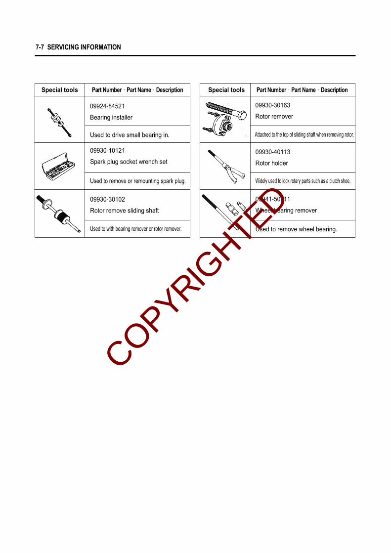
Used to remove or remounting spark plug.
09930-30102
Rotor remove sliding shaft
09930-10121
Spark plug socket wrench set
Used to with bearing remover or rotor remover.
09924-84521
Bearing installer
Used to drive small bearing in.
7-7 SERVICING INFORMATION
Special tools Part Number∙Part Name∙Description Part Number∙Part Name∙Description
Used to remove wheel bearing.
09941-50111
Wheel bearing remover
09930-30163
Rotor remover
Special tools
Attached to the top of sliding shaft when removing rotor.
09930-40113
Rotor holder
Widely used to lock rotary parts such as a clutch shoe.
COPYRIGHTED
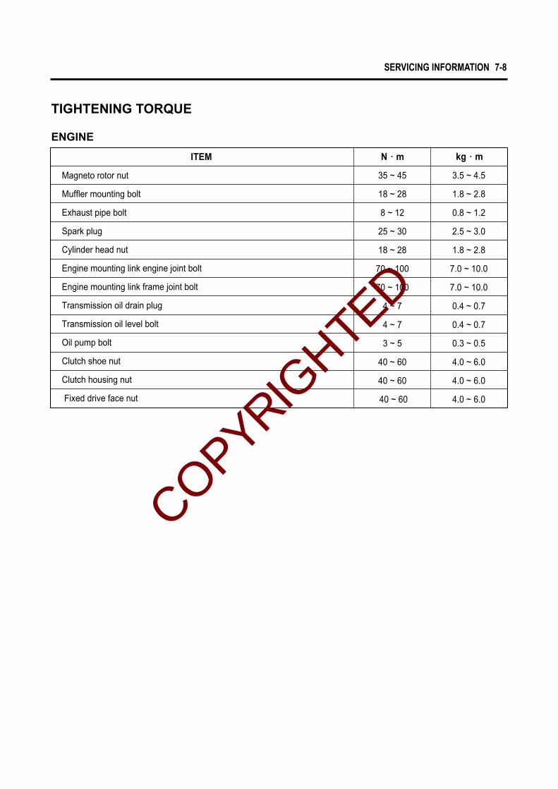
SERVICING INFORMATION 7-8
35 ~ 45
18 ~ 28
8 ~ 12
25 ~ 30
18 ~ 28
70 ~ 100
70 ~ 100
4 ~ 7
4 ~ 7
3 ~ 5
40 ~ 60
40 ~ 60
40 ~ 60
3.5 ~ 4.5
1.8 ~ 2.8
0.8 ~ 1.2
2.5 ~ 3.0
1.8 ~ 2.8
7.0 ~ 10.0
7.0 ~ 10.0
0.4 ~ 0.7
0.4 ~ 0.7
0.3 ~ 0.5
4.0 ~ 6.0
4.0 ~ 6.0
4.0 ~ 6.0
kg∙∙mN∙∙mITEM
Magneto rotor nut
Muffler mounting bolt
Exhaust pipe bolt
Spark plug
Cylinder head nut
Engine mounting link engine joint bolt
Engine mounting link frame joint bolt
Transmission oil drain plug
Transmission oil level bolt
Oil pump bolt
Clutch shoe nut
Clutch housing nut
Fixed drive face nut
TIGHTENING TORQUE
ENGINE
COPYRIGHTED

7-9 SERVICING INFORMATION
TIGHTENING TORQUE CHARTFor other bolts and nuts who’s torque is not listed, refer to this chart :
Conventional or ““4””marked boltBolt Diameter(mm)
““7””marked bolt
4
5
6
8
10
12
14
16
18
1.0 ~ 2.0
2.0 ~ 4.0
4.0 ~ 7.0
10.0 ~ 16.0
22.0 ~ 35.0
35.0 ~ 55.0
50.0 ~ 80.0
80.0 ~ 130.0
130.0 ~ 190.0
0.1 ~ 0.2
0.2 ~ 0.4
0.4 ~ 0.7
1.0 ~ 1.6
2.2 ~ 3.5
3.5 ~ 5.5
5.0 ~ 8.0
8.0 ~ 13.0
13.0 ~ 19.0
1.5 ~ 3.0
3.0 ~ 6.0
8.0 ~ 12.0
18.0 ~ 28.0
40.0 ~ 60.0
70.0 ~ 100.0
110.0 ~ 160.0
170.0 ~ 250.0
200.0 ~ 280.0
0.15 ~ 0.3
0.3 ~ 0.6
0.8 ~ 1.2
1.8 ~ 2.8
4.0 ~ 6.0
7.0 ~ 10.0
11.0 ~ 16.0
17.0 ~ 25.0
20.0 ~ 28.0
kg∙∙mN∙∙m kg∙∙mN∙∙m
ITEM
Front brake cam lever nut
Front shock absorber bolt & nut
Rear sprocket nut
Rear shock absorber bolt
Rear axle nut (M28)
Rear brake caliper lever bolt
Rear brake disc bolt
Rear brake caliper mounting bolt
Front axle nut (M14)
Handlebar holder bolt
Tie-rod lock nut
Steering shaft bolt (M8)
Steering shaft lower nut
6 ~ 8
40 ~ 50
22 ~ 35
40 ~ 50
120 ~ 150
6 ~ 8
22 ~ 35
5 ~ 7
50 ~ 80
18.4 ~ 28.6
22.4 ~ 35.7
18 ~ 28
22.4 ~35.7
0.6 ~ 0.8
4.0 ~ 5.0
2.2 ~ 3.5
4.0 ~ 5.0
12.0 ~ 15.0
0.6 ~ 0.8
2.2 ~ 3.5
0.5 ~ 0.7
5.0 ~ 8.0
1.84 ~ 2.86
2.24 ~ 3.57
1.8 ~ 2.8
2.24 ~3.57
kg∙∙mN∙∙m
CHASSIS
COPYRIGHTED

SERVICING INFORMATION 7-10
SERVICE DATA
ITEM
Cylinder to piston clearance
Cylinder bore
Piston diam.
0.073 ~0.083 (0.0029 ~ 0.0033)
12.002 ~ 12.010 (0.4725 ~ 0.4728)
11.994 ~ 12.000 (0.4722 ~ 0.6302)
0.120 (0.0047)
52.332 (2.0603)
0.05 (0.002)
0.05 (0.002)
3.6 (0.142)
3.6 (0.142)
0.75 (0.030)
0.75 (0.030)
12.030 (0.4736)
11.980 (0.4717)
52.432 ~ 52.447 (2.0643 ~2.0648)Measure at 20mm from the skirt end
52.500 ~ 52.515 (2.0669 ~2.0675)Measure at 20mm from the top surface
Approx. 4.5 (0.177)
Approx. 4.5 (0.177)
0.10 ~ 0.25 (0.004 ~ 0.010)
0.10 ~ 0.25 (0.004 ~ 0.010)
0.02 ~ 0.06 (0.0008 ~ 0.0024)
0.02 ~ 0.06 (0.0008 ~ 0.0024)
Cylinder distortion
Cylinder head distortion
Piston ring clearance(Free condition)
Piston ring clearance(Assembling condition)
Piston ring - ring groove clearance
Piston pin bore I.D
Piston pin O.D
STANDARD LIMIT
1st
2nd
1st
2nd
1st
2nd
CYLINDER + PISTON + PISTON RING Unit : mm (in)
Unit : mm (in)CONROD + CRANKSHAFT
ITEM
Conrod small end bore I.D.
Conrod big end runout
Crank web to wed width
Crankshaft runout
16.004 ~ 16.008 (0.6301 ~0.6302)
40.0 ± 0.1 (1.575 ± 0.004)
16.040 (0.6315)
3.0 (0.12)
0.05 (0.002)
STANDARD LIMIT
52.590 (2.0705)
COPYRIGHTED

7-11 SERVICING INFORMATION
Unit : mm (in)CLUTCH
ITEM
Clutch housing I.D. 112.00(4.4095)
112.50(4.4291)
2.0(0.079)
4.5(0.177)
Clutch shoe thickness
Clutch in rpm
Clutch tight rpm
3,900 ± 200 rpm
5,900 ± 200 rpm
STANDARD LIMIT
Unit : mm (in) Except ratioTRANSMISSION+DRIVE CHAIN
ITEM
Final reduction ratio 1.33
428H
56
259 (10.197)254 (10.000)
5 ~ 15 (0.197 ~ 0.591) Over 15 (Over 0.591)
8.62Gear ratio
Transmission
Drive V-belt width
2.842 ~ 1.042
16.4 ~ 16.6(0.6457 ~ 0.6535)
136.4(5.370)
Type
Links
20 - pitch length
Drive chain
Drive chain slack
16.0(0.6299)
130.0(5.118)
STANDARD LIMIT
Movable drive face spring free length
OIL PUMP
ITEM
Oil pump reduction ratio 30 : 1
STANDARD
COPYRIGHTED

SERVICING INFORMATION 7-12
Unit : mm (in)CARBURETOR
ITEM
PB11M
16.0 (0.630)
HL41
1,800 ± 100 rpm
8.0 (0.315)
# 70
ф 2.1
2JM
ф 2.1
ф 2.1
# 45
3.5
ф 1.0
1.0 (0.039)
# 45
18�
0.8 (0.032)
0.5 ~ 1.0 (0.020 ~ 0.039)
SPECIFICATION
Carburetor type
Bore size
I.D. No.
Idle rpm
Fuel level
Main jet
Main air jet
Jet needle
Pilot jet
Needle jet
Pilot air jet
Throttle valve
By-pass
Valve seat
Starter jet
Pilot screw
Pilot outlet
Throttle cable play
(M.J.)
(M.A.J.)
(J.N.)
(N.J.)
(P.A.J.)
(P.J.)
(T.V.)
(B.P.)
(V.S.)
(G.S.)
(P.S.)
(P.O.)
COPYRIGHTED

7-13 SERVICING INFORMATION
Unit : mm (in)ELECTRICAL
ITEM SPECIFICATION NOTE
Ignition timing
Spark plug
B.T.D.C. 8�at 1,000 rpm and B.T.D.C. 20�at 4,000 rpm
BPR7HS
0.6 ~ 0.7(0.024 ~ 0.028)
BPR7HS
BPR8HS
BPR6HS
Type
Gap
Hot type
Standard type
Cold type
Spark performance
Ignition coil resistance
Stator coil resistance
Regulated voltage
Starter motor carbon brush length
Starter motor commutator under-cut
Starter relay resistance
Battery Capacity
Type designation
Standardelectrolyte S.G.
Fuse size
No-load performance of A.C. generator
B/R-Ground
Br - W
Y/W-Ground
W/R-Ground
Over 8 (0.3) at 1 atm
5.4 ~ 6.6 ㏀
0.19 ~ 0.24 Ϊ
0.69 ~ 1.03 Ϊ
0.54 ~ 0.80 Ϊ
146 ~ 220 Ϊ
90 ~ 110 Ϊ
13.0 ~ 16.0 V at 5,000 rpm
3.5 (0.138)
0.2 (0.008)
80 ~ 150 Ϊ
STX5L-BS (MF)
12V 4Ah/10HR
10A
More than 17.0V (at 5,000 rpm)
1.32 at 20℃ (68℉)
Secondary
Primary
Charging coil
Lighting coil
Exciting coil
Pick-up coil
COPYRIGHTED

SERVICING INFORMATION 7-14
Unit : mm (in)BRAKE + WHEEL
ITEM
Brake lever play
Brake pedal play
Brake drum I.D.
Brake shoe lining O.D.
Brake shoe thickness
Brake disc thickness
Brake disc runout
Turning radius
Camber
Toe-in
110.0(4.330)
110.0(4.330)
4.0(0.158)
3.0(0.118)
2,595(102.165)
1。
8.0(0.315)
15(0.591)
5 ~15 (0.197 ~ 0.591)
15 ~25 (0.591 ~ 0.984)
106.0(4.173)
2.0(0.079)
110.7(4.358)
2.5(0.098)
0.3(0.012)
STANDARD LIMIT
Front
Rear
Front
Front
Front
Rear
Rear
Caster
Trail
Wheel rim runout
Wheel axle shaft runout
Tire size
Tire tread depth
5。
18 × 7.00 - 7
18 × 7.00 - 7
1.2(0.047)
1.2(0.047)
0.5(0.020)
10(0.394)
10(0.394)
Axial
Radial
Rear
Front
Rear
Front
Rear
COPYRIGHTED

7-15 SERVICING INFORMATION
ITEM
Fuel type
FUEL + OIL
Gasoline used should be graded 85 ~ 95 octane or higher. Anunleaded gasoline is recommended.
Use HYOSUNG HYPOL HS OIL or an equivalent good qualitysynthetic based 2-stroke engine oil.
4.0 ℓ
1.0 ℓ
2.6 ~ 2.8 ㎖(at 3,000rpm for 5 minutes)
SAE 10W/30 or 10W/40 multi - grade motor oil
80 ㎖Change
Overhaul 90 ㎖
Fuel tank capacity
Engine oil type
Engine oil tank capacity
Engine oil discharge amount
Transmission oil capacity
Transmission oil type
SPECIFICATION NOTE
TIRE PRESSURE
SUSPENSION
COLD INFLATIONTIRE PRESSURE
FRONT
REAR
kPa kgf/㎠㎠ psi
25
25
0.25
0.25
3.6
3.6
ITEM SPECIFICATION LIMIT
Front wheal travel
Rear wheel travel
75 (2.953)
56.6 (2.228)
Unit: mm (in)
COPYRIGHTED

SERVICING INFORMATION 7-16
WIRE AND CABLE ROUTING
EM
ERG
EN
CY S
WIT
CH 0
9407-
14403
09407-
14403
09407-
14403
WIR
E A
ND
CABLE G
UID
E
SW
ITC
H A
SS’Y
, H
AN
DLE L
H
SW
ITC
H A
SS’Y
, STO
P F
RO
NT
SW
ITC
H A
SS’Y
, STEERIN
G
IGIN
TIO
N C
OIL
CD
I U
NIT
09407-
14403
SEPARATIN
G P
OIN
T
BATTERY +
BATTERY -
FU
SE
HARN
ESS
REG
ULATO
R
MAG
NETO
P.T
.C
STA
RTE
R R
ELA
Y
EN
GIN
E E
ARTHC
OPYRIGHTED

7-17 SERVICING INFORMATION
B
A
EM
ERG
EN
CY S
WIT
CH
CASE
09407-
18401
COPYRIGHTED

SERVICING INFORMATION 7-18
BATTERY
FUSE
STARTER RELAY
09407-14403
VIEW A
VIEW B
MAGNETO
START MOTOR
COPYRIGHTED

7-19 SERVICING INFORMATION
09407-14403
09407-14403HANDLE SWITCH LH
FRONT STOP SWITCH
HANDLE SWITCH LH / STOP SWITCH
CDI UNIT ASSEMBLY POSITION
CDI UNIT
FRONT FENDER
COPYRIGHTED

FREE
PUSH
OFF ON
WL
WB
WBr
BWBY
BR
WL
WBr
BWBR
RB
BW
BWW
R
BW
BW BR
BW BR
PUSH
FREE
YW
R
BRR
O
BWBR
RO
O
S/W
BRAKE F
RO
NT
S/W
IGN
ITIO
N
IGN
ITIO
N C
OIL
C.D
.I U
NIT
S/W
EM
ERG
EN
CY
STA
RT
MO
TOR
RELA
Y S
TARTE
R
FU
SE
P.T
.C.
WR
MAG
NETO
10A
R
RB
BR
RW
RW
WR
YW
WB
YG
YW
BW
Br
BR
W
BR
BW
YG
WB
WL
BR
BW
YG
WB
WR
Br
W
SPARK P
LUG
STA
RTE
R
FREE
PU
SH
STO
P
RU
N
EN
GIN
E K
ILL
HAN
DLE
SW
ITC
H L
H
BW
YG
B
R
R
BW
YG
RW
RBW
REC
TIFIE
RREG
ULA
TOR
EN
GIN
E E
ARTH
BATT
ERY
12V
WIRING DIAGRAM
WIR
E C
OLO
R
B
: Bla
ckLg
: Lig
ht g
reen
Y: Y
ello
wR
B: R
ed w
ith B
lack
trac
erB
r: B
row
nO
: Ora
nge
BG
: Bla
ck w
ith G
reen
trac
erR
W: R
ed w
ith W
hite
trac
erG
: Gre
enR
: Red
BW
: Bla
ck w
ith W
hite
trac
erW
B: W
hite
with
Bla
ck tr
acer
Gr
: Gra
yS
b: L
ight
blu
eB
R: B
lack
with
Red
trac
erW
R: W
hite
with
Red
trac
erL
: Blu
eW
: Whi
teLW
: Blu
e w
ith W
hite
trac
erY
B: Y
ello
w w
ith B
lack
trac
er
SERVICING INFORMATION 7-20BW
BRR
O
YG
: Yel
low
with
Gre
en tr
acer
COPYRIGHTED

Prepared by
HYOSUNG MOTORS & MACHINERY INC.Overseas Technical Department
1st Ed. AUG. 2001.
Manual No. 99000-94310Printed in Korea
COPYRIGHTED