service manual - daikinac.com · service manual inverter pair ... part 6 service diagnosis.....50...
TRANSCRIPT

Service Manual
Inverter PairWall Mounted Type FTX-N Series
SiUS041638E
[Applied Models] Inverter Pair : Cooling Only Inverter Pair : Heat Pump
SiUS041638E
Inverter PairWall Mounted Type
FTX-N SeriesCooling Only
Indoor UnitFTX30NVJUFTX36NVJU
Outdoor UnitRK30NMVJURK36NMVJU
Heat Pump
Indoor UnitFTX30NVJUFTX36NVJU
Outdoor UnitRX30NMVJURX36NMVJU
i Table of Contents
SiUS041638E
1. Safety Cautions........................................................................................... v1.1 Warnings and Cautions Regarding Safety of Workers................................. v1.2 Warnings and Cautions Regarding Safety of Users....................................vii
2. Icons Used .................................................................................................. x
Part 1 List of Functions ................................................................... 11. Functions.....................................................................................................2
Part 2 Specifications ....................................................................... 31. Specifications ..............................................................................................4
1.1 Cooling Only................................................................................................. 41.2 Heat Pump ................................................................................................... 5
Part 3 Printed Circuit Board Connector Wiring Diagram ................61. Indoor Unit...................................................................................................7
1.1 FTX30/36NVJU ............................................................................................ 7
2. Outdoor Unit................................................................................................92.1 RK(X)30/36NMVJU ...................................................................................... 9
Part 4 Functions and Control......................................................... 121. Main Functions..........................................................................................13
1.1 Temperature Control .................................................................................. 131.2 Frequency Principle.................................................................................... 131.3 Airflow Direction Control............................................................................. 151.4 Fan Speed Control for Indoor Unit ............................................................. 161.5 Program Dry Operation .............................................................................. 171.6 Automatic Operation................................................................................... 181.7 Thermostat Control..................................................................................... 191.8 NIGHT SET Mode ...................................................................................... 201.9 ECONO Operation ..................................................................................... 201.10 INTELLIGENT EYE Operation ................................................................... 211.11 POWERFUL Operation .............................................................................. 221.12 Clock Setting .............................................................................................. 231.13 WEEKLY TIMER Operation ....................................................................... 241.14 Other Functions.......................................................................................... 30
2. Thermistor Functions ................................................................................313. Control Specification .................................................................................33
3.1 Mode Hierarchy .......................................................................................... 333.2 Frequency Control...................................................................................... 343.3 Controls at Mode Changing/Start-up.......................................................... 363.4 Discharge Pipe Temperature Control......................................................... 383.5 Input Current Control.................................................................................. 393.6 Freeze-up Protection Control ..................................................................... 403.7 Heating Peak-cut Control ........................................................................... 403.8 Outdoor Fan Control................................................................................... 41
Table of Contents ii

SiUS041638E
3.9 Liquid Compression Protection Function.................................................... 413.10 Defrost Control ........................................................................................... 423.11 Electronic Expansion Valve Control ........................................................... 433.12 Malfunctions ............................................................................................... 46
Part 5 Remote Controller ............................................................... 471. Remote Controller .....................................................................................48
Part 6 Service Diagnosis................................................................ 501. General Problem Symptoms and Check Items .........................................522. Troubleshooting with LED .........................................................................53
2.1 Indoor Unit.................................................................................................. 532.2 Outdoor Unit ............................................................................................... 53
3. Service Diagnosis .....................................................................................544. Troubleshooting ........................................................................................57
4.1 Error Codes and Description ...................................................................... 574.2 Indoor Unit PCB Abnormality ..................................................................... 584.3 Freeze-up Protection Control/Heating Peak-cut Control ............................ 604.4 Indoor Fan Motor (DC Motor) or Related Abnormality ............................... 614.5 Thermistor or Related Abnormality (Indoor Unit)........................................ 634.6 Low-voltage Detection or Over-voltage Detection...................................... 644.7 Signal Transmission Error (between Indoor Unit and Outdoor Unit) .......... 664.8 Signal Transmission Error on Outdoor Unit PCB ....................................... 684.9 Mismatching of Indoor Unit and Outdoor Unit ............................................ 694.10 Outdoor Unit PCB Abnormality................................................................... 704.11 OL Activation (Compressor Overload) ....................................................... 714.12 Compressor Lock ....................................................................................... 734.13 DC Fan Lock (Outdoor Fan)....................................................................... 744.14 Input Overcurrent Detection ....................................................................... 754.15 Four Way Valve Abnormality...................................................................... 764.16 Discharge Pipe Temperature Control......................................................... 784.17 High Pressure Control in Cooling ............................................................... 794.18 System Shutdown due to Compressor Internal Temperature
Abnormality ................................................................................................ 804.19 Compressor System Sensor Abnormality .................................................. 814.20 Position Sensor Abnormality ...................................................................... 824.21 CT or Related Abnormality ......................................................................... 844.22 Thermistor or Related Abnormality (Outdoor Unit)..................................... 864.23 Electrical Box Temperature Rise................................................................ 884.24 Radiation Fin Temperature Rise ................................................................ 894.25 Output Overcurrent Detection .................................................................... 90
5. Check ........................................................................................................925.1 Thermistor Resistance Check .................................................................... 925.2 Indoor Fan Motor Connector Output Check ............................................... 935.3 Power Supply Waveforms Check............................................................... 935.4 Electronic Expansion Valve Check............................................................. 94
iii Table of Contents
SiUS041638E
5.5 Four Way Valve Performance Check ......................................................... 955.6 Inverter Unit Refrigerant System Check..................................................... 955.7 Inverter Analyzer Check ............................................................................. 965.8 Rotation Pulse Check on the Outdoor Unit PCB ........................................ 985.9 Installation Condition Check....................................................................... 995.10 Discharge Pressure Check......................................................................... 995.11 Outdoor Fan System Check ..................................................................... 1005.12 Main Circuit Short Check.......................................................................... 1005.13 Capacitor Voltage Check.......................................................................... 1015.14 Power Module Check ............................................................................... 101
Part 7 Trial Operation and Field Settings....................................1031. Pump Down Operation............................................................................1042. Forced Cooling Operation .......................................................................1053. Trial Operation ........................................................................................1064. Field Settings ..........................................................................................107
4.1 Model Type Setting .................................................................................. 1074.2 Temperature Display Switch .................................................................... 1074.3 When 2 Units are Installed in 1 Room...................................................... 1084.4 Facility Setting Switch (cooling at low outdoor temperature).................... 109
5. Silicone Grease on Power Transistor/Diode Bridge................................111
Part 8 Appendix............................................................................1121. Piping Diagrams......................................................................................113
1.1 Indoor unit ................................................................................................ 1131.2 Outdoor Unit ............................................................................................. 114
2. Wiring Diagrams......................................................................................1152.1 Indoor Unit................................................................................................ 1152.2 Outdoor Unit ............................................................................................. 116
3. Operation Limit........................................................................................117
Table of Contents iv
Safety Cautions SiUS041638E
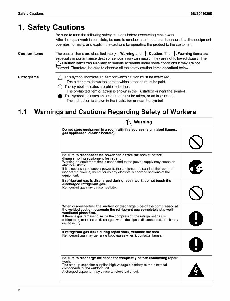
1. Safety CautionsBe sure to read the following safety cautions before conducting repair work.After the repair work is complete, be sure to conduct a test operation to ensure that the equipment operates normally, and explain the cautions for operating the product to the customer.
Caution Items The caution items are classified into Warning and Caution. The Warning items are especially important since death or serious injury can result if they are not followed closely. The
Caution items can also lead to serious accidents under some conditions if they are not followed. Therefore, be sure to observe all the safety caution items described below.
Pictograms This symbol indicates an item for which caution must be exercised. The pictogram shows the item to which attention must be paid.
This symbol indicates a prohibited action. The prohibited item or action is shown in the illustration or near the symbol.
This symbol indicates an action that must be taken, or an instruction. The instruction is shown in the illustration or near the symbol.
1.1 Warnings and Cautions Regarding Safety of WorkersWarning
Do not store equipment in a room with fire sources (e.g., naked flames, gas appliances, electric heaters).
Be sure to disconnect the power cable from the socket before disassembling equipment for repair.Working on equipment that is connected to the power supply may cause an electrical shock.If it is necessary to supply power to the equipment to conduct the repair or inspect the circuits, do not touch any electrically charged sections of the equipment.
If refrigerant gas is discharged during repair work, do not touch the discharged refrigerant gas.Refrigerant gas may cause frostbite.
When disconnecting the suction or discharge pipe of the compressor at the welded section, evacuate the refrigerant gas completely at a well-ventilated place first.If there is gas remaining inside the compressor, the refrigerant gas or refrigerating machine oil discharges when the pipe is disconnected, and it may cause injury.
If refrigerant gas leaks during repair work, ventilate the area. Refrigerant gas may generate toxic gases when it contacts flames.
Be sure to discharge the capacitor completely before conducting repair work.The step-up capacitor supplies high-voltage electricity to the electrical components of the outdoor unit.A charged capacitor may cause an electrical shock.
v
SiUS041638E Safety Cautions
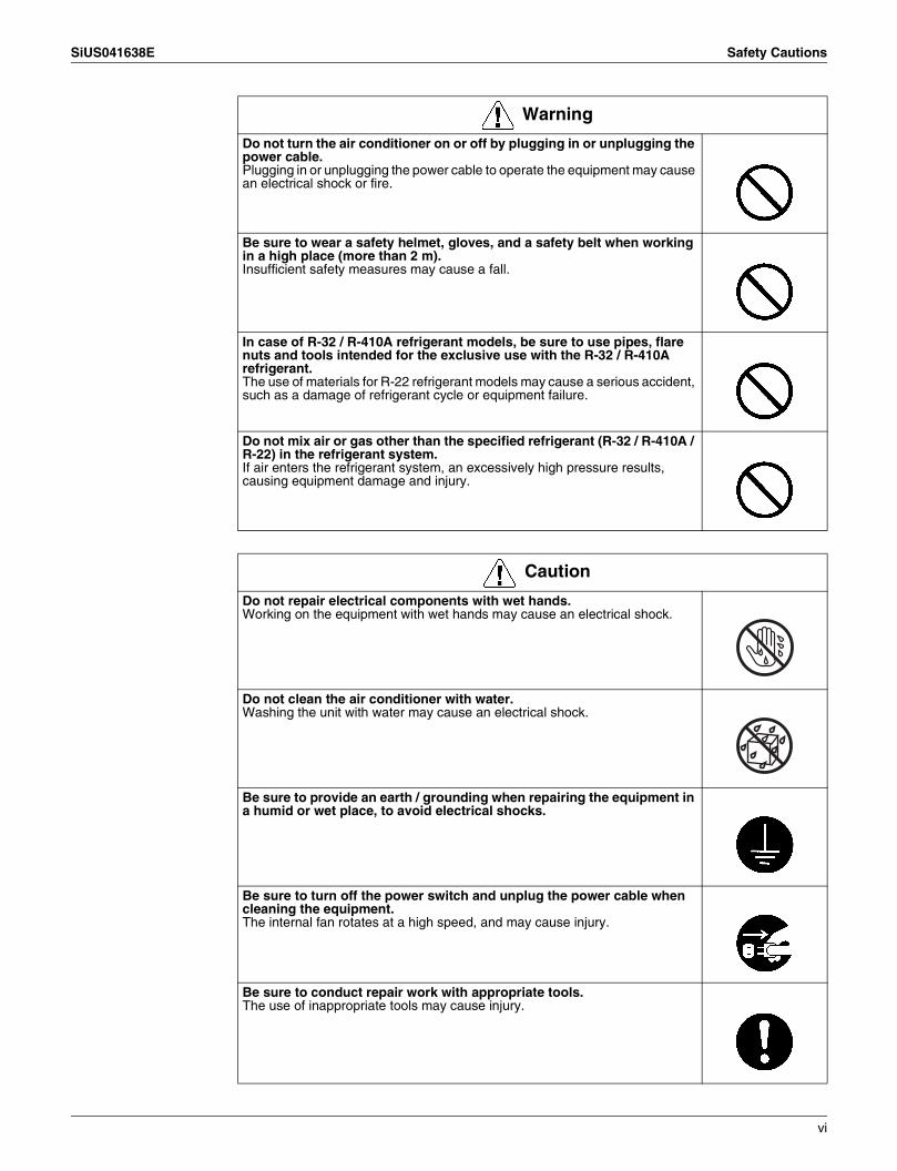
Do not turn the air conditioner on or off by plugging in or unplugging the power cable.Plugging in or unplugging the power cable to operate the equipment may cause an electrical shock or fire.
Be sure to wear a safety helmet, gloves, and a safety belt when working in a high place (more than 2 m).Insufficient safety measures may cause a fall.
In case of R-32 / R-410A refrigerant models, be sure to use pipes, flare nuts and tools intended for the exclusive use with the R-32 / R-410A refrigerant.The use of materials for R-22 refrigerant models may cause a serious accident, such as a damage of refrigerant cycle or equipment failure.
Do not mix air or gas other than the specified refrigerant (R-32 / R-410A / R-22) in the refrigerant system.If air enters the refrigerant system, an excessively high pressure results, causing equipment damage and injury.
Warning
Caution
Do not repair electrical components with wet hands.Working on the equipment with wet hands may cause an electrical shock.
Do not clean the air conditioner with water.Washing the unit with water may cause an electrical shock.
Be sure to provide an earth / grounding when repairing the equipment in a humid or wet place, to avoid electrical shocks.
Be sure to turn off the power switch and unplug the power cable when cleaning the equipment.The internal fan rotates at a high speed, and may cause injury.
Be sure to conduct repair work with appropriate tools.The use of inappropriate tools may cause injury.
vi

Safety Cautions SiUS041638E
1.2 Warnings and Cautions Regarding Safety of Users
Be sure to check that the refrigerating cycle section has cooled down enough before conducting repair work.Working on the unit when the refrigerating cycle section is hot may cause burns.
Conduct welding work in a well-ventilated place.Using a welder in an enclosed room may cause oxygen deficiency.
Caution
Warning
Do not store the equipment in a room with fire sources (e.g., naked flames, gas appliances, electric heaters).
Be sure to use parts listed in the service parts list of the applicable model and appropriate tools to conduct repair work. Never attempt to modify the equipment.The use of inappropriate parts or tools may cause an electrical shock, excessive heat generation or fire.
If the power cable and lead wires are scratched or have deteriorated, be sure to replace them.Damaged cable and wires may cause an electrical shock, excessive heat generation or fire.
Do not use a joined power cable or extension cable, or share the same power outlet with other electrical appliances, since it may cause an electrical shock, excessive heat generation or fire.
Be sure to use an exclusive power circuit for the equipment, and follow the local technical standards related to the electrical equipment, the internal wiring regulations, and the instruction manual for installation when conducting electrical work.Insufficient power circuit capacity and improper electrical work may cause an electrical shock or fire.
Be sure to use the specified cable for wiring between the indoor and outdoor units.Make the connections securely and route the cable properly so that there is no force pulling the cable at the connection terminals.Improper connections may cause excessive heat generation or fire.
vii

SiUS041638E Safety Cautions
When wiring between the indoor and outdoor units, make sure that the terminal cover does not lift off or dismount because of the cable.If the cover is not mounted properly, the terminal connection section may cause an electrical shock, excessive heat generation or fire.
Do not damage or modify the power cable.Damaged or modified power cables may cause an electrical shock or fire.Placing heavy items on the power cable, or heating or pulling the power cable may damage it.
Do not mix air or gas other than the specified refrigerant (R-32 / R-410A / R-22) in the refrigerant system.If air enters the refrigerant system, an excessively high pressure results, causing equipment damage and injury.
If the refrigerant gas leaks, be sure to locate the leaking point and repair it before charging the refrigerant. After charging the refrigerant, make sure that there is no leak.If the leaking point cannot be located and the repair work must be stopped, be sure to pump-down, and close the service valve, to prevent refrigerant gas from leaking into the room. Refrigerant gas itself is harmless, but it may generate toxic gases when it contacts flames, such as those from fan type and other heaters, stoves and ranges.
When relocating the equipment, make sure that the new installation site has sufficient strength to withstand the weight of the equipment.If the installation site does not have sufficient strength or the installation work is not conducted securely, the equipment may fall and cause injury.
Check to make sure that the power cable plug is not dirty or loose, then insert the plug into a power outlet securely.If the plug is dusty or has a loose connection, it may cause an electrical shock or fire.
When replacing the coin battery in the remote controller, be sure to dispose of the old battery to prevent children from swallowing it.If a child swallows the coin battery, see a doctor immediately.
Warning
viii
Safety Cautions SiUS041638E
Caution
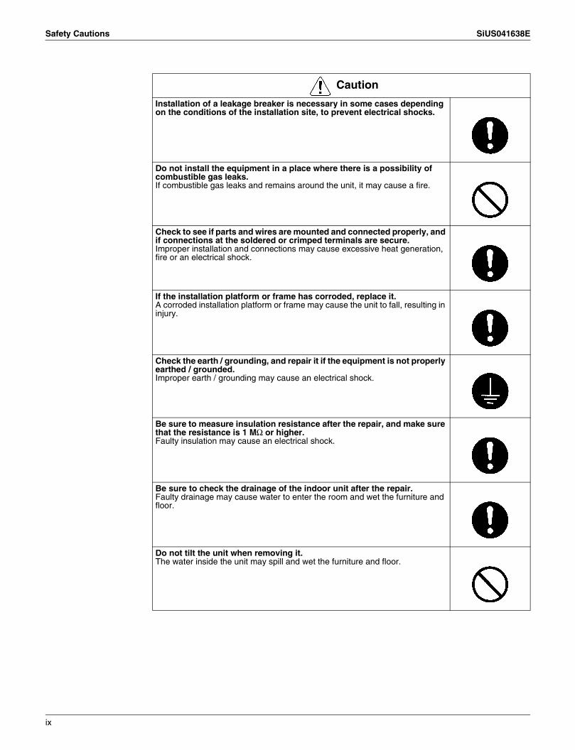
Installation of a leakage breaker is necessary in some cases depending on the conditions of the installation site, to prevent electrical shocks.
Do not install the equipment in a place where there is a possibility of combustible gas leaks.If combustible gas leaks and remains around the unit, it may cause a fire.
Check to see if parts and wires are mounted and connected properly, and if connections at the soldered or crimped terminals are secure.Improper installation and connections may cause excessive heat generation, fire or an electrical shock.
If the installation platform or frame has corroded, replace it.A corroded installation platform or frame may cause the unit to fall, resulting in injury.
Check the earth / grounding, and repair it if the equipment is not properly earthed / grounded.Improper earth / grounding may cause an electrical shock.
Be sure to measure insulation resistance after the repair, and make sure that the resistance is 1 MΩ or higher.Faulty insulation may cause an electrical shock.
Be sure to check the drainage of the indoor unit after the repair.Faulty drainage may cause water to enter the room and wet the furniture and floor.
Do not tilt the unit when removing it.The water inside the unit may spill and wet the furniture and floor.
ix
SiUS041638E Icons Used
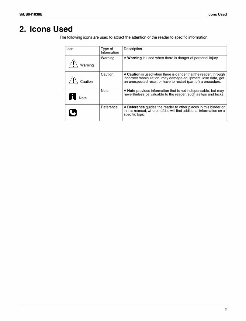
2. Icons UsedThe following icons are used to attract the attention of the reader to specific information.
Icon Type of Information
Description
Warning
Warning A Warning is used when there is danger of personal injury.
Caution
Caution A Caution is used when there is danger that the reader, through incorrect manipulation, may damage equipment, lose data, get an unexpected result or have to restart (part of) a procedure.
Note:
Note A Note provides information that is not indispensable, but may nevertheless be valuable to the reader, such as tips and tricks.
Reference A Reference guides the reader to other places in this binder or in this manual, where he/she will find additional information on a specific topic.
x
SiUS041638E
1 List of Functions
Part 1List of Functions
1. Functions.....................................................................................................2
SiUS041638E Functions
List of Functions 2
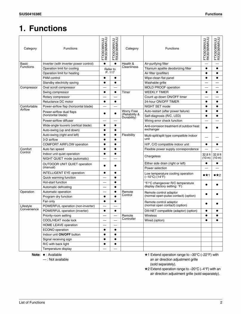
1. Functions
Category Functions
FT
X30
/36N
VJU
RK
30/3
6NM
VJU
FT
X30
/36N
VJU
RX
30/3
6NM
VJU
Category Functions
FT
X30
/36N
VJU
RK
30/3
6NM
VJU
FT
X30
/36N
VJU
RX
30/3
6NM
VJU
Basic Functions
Inverter (with inverter power control) Health & Cleanliness
Air-purifying filter — —
Operation limit for cooling Refer to P. 117
Titanium apatite deodorizing filter
Operation limit for heating Air filter (prefilter)
PAM control Wipe-clean flat panel
Standby electricity saving Washable grille — —
Compressor Oval scroll compressor — — MOLD PROOF operation — —
Swing compressor Timer WEEKLY TIMER
Rotary compressor — — Count up-down ON/OFF timer — —
Reluctance DC motor 24-hour ON/OFF TIMER
Comfortable Airflow
Power-airflow flap (horizontal blade) — — NIGHT SET mode
Power-airflow dual flaps (horizontal blade)
Worry Free (Reliability & Durability)
Auto-restart (after power failure)
Self-diagnosis (R/C, LED)
Power-airflow diffuser — — Wiring error check function — —
Wide-angle louvers (vertical blade) Anti-corrosion treatment of outdoor heat exchangerAuto-swing (up and down)
Auto-swing (right and left) Flexibility Multi-split/split type compatible indoor unit — —
3-D airflow
COMFORT AIRFLOW operation H/P, C/O compatible indoor unit
Comfort Control
Auto fan speed Flexible power supply correspondence — —
Indoor unit quiet operationChargeless 32.8 ft
(10 m)32.8 ft(10 m)NIGHT QUIET mode (automatic) — —
OUTDOOR UNIT QUIET operation (manual)
Either side drain (right or left)
Power selection — —
INTELLIGENT EYE operation Low temperature cooling operation (–10°C) (14°F) 1 2
Quick warming function —
Hot-start function — °F/°C changeover R/C temperature display (factory setting: °F)Automatic defrosting —
Operation Automatic operation — Remote Control
Remote control adaptor (normal open-pulse contact) (option)Program dry function
Fan only Remote control adaptor (normal open contact) (option)Lifestyle
ConveniencePOWERFUL operation (non-inverter) — —
POWERFUL operation (inverter) DIII-NET compatible (adaptor) (option)
Priority-room setting — — Remote Controller
Wireless
COOL/HEAT mode lock — — Wired (option)
HOME LEAVE operation — —
ECONO operation
Indoor unit ON/OFF button
Signal receiving sign
R/C with back light
Temperature display — —
Note: : Available— : Not available
1 Extend operation range to –30°C (–22°F) with an air direction adjustment grille (sold separately).
2 Extend operation range to –20°C (–4°F) with an air direction adjustment grille (sold separately).
SiUS041638E
3 Specifications
Part 2Specifications
1. Specifications ..............................................................................................41.1 Cooling Only................................................................................................. 41.2 Heat Pump ................................................................................................... 5

SiUS041638E Specifications
1. Specifications1.1 Cooling Only
60 Hz, 208 - 230 V
Notes: 1. SL: The Quiet fan level of the airflow rate setting.2. The data are based on the conditions shown in the table below.
ModelIndoor Unit FTX30NVJU FTX36NVJUOutdoor Unit RK30NMVJU RK36NMVJU
CapacityRated Btu/h 31,400 - 31,400 33,200 - 34,400
Min. ~ Max. Btu/h 10,200 - 10,200 ~ 31,400 - 31,400 10,200 - 10,200 ~ 33,200 - 34,400Running Current (Rated) A 15.7 - 14.2 17 - 17
Power ConsumptionRated W 3,188 - 3,188 3,458 - 3,780
Min. ~ Max. W 610 - 610 ~ 3,188 - 3,188 620 - 620 ~ 3,458 - 3,780Power Factor (Rated) % 97.6 - 97.6 97.8 - 96.7COP (Rated) W/W — —EER (Rated) Btu/W·h 9.85 9.6 - 9.1SEER / HSPF 17.50 15.90
Piping ConnectionsLiquid in. (mm) φ 1/4 (φ 6.4) φ 1/4 (φ 6.4)Gas in. (mm) φ 5/8 (φ 15.9) φ 5/8 (φ 15.9)Drain in. (mm) φ 5/8 (φ 16.0) φ 5/8 (φ 16.0)
Heat Insulation Both Liquid and Gas Pipes Both Liquid and Gas PipesMax. Interunit Piping Length ft (m) 98-3/8 (30) 98-3/8 (30)Max. Interunit Height Difference ft (m) 65-5/8 (20) 65-5/8 (20)Chargeless ft (m) 32-13/16 (10) 32-13/16 (10)Amount of Additional Charge of Refrigerant
oz/ft(g/m) 0.32 (30) 0.32 (30)
Indoor Unit FTX30NVJU FTX36NVJUFront Panel Color White White
Airflow Rate
Hcfm
(m³/min)
890 (25.2) 915 (25.9)M 727 (20.6) 742 (21.0)L 572 (16.2) 572 (16.2)SL 512 (14.5) 512 (14.5)
FanType Cross Flow Fan Cross Flow FanSpeed Steps 5 Steps, Quiet, Auto 5 Steps, Quiet, Auto
Air Direction Control Right, Left, Horizontal, Downward Right, Left, Horizontal, DownwardAir Filter Removable, Washable, Mildew Proof Removable, Washable, Mildew ProofRunning Current (Rated) A 0.8 - 0.7 0.8 - 0.8Power Consumption (Rated) W 90.0 - 90.0 95.0 - 95.0Power Factor (Rated) % 56.2 - 55.9 55.7 - 55.1Temperature Control Microcomputer Control Microcomputer ControlDimensions (H × W × D) in. (mm) 13-3/8 × 47-1/4 × 10-3/16 (340 × 1,200 × 259) 13-3/8 × 47-1/4 × 10-3/16 (340 × 1,200 × 259)Packaged Dimensions (H × W × D) in. (mm) 13-7/16 × 51-9/16 × 16-7/8 (342 × 1,310 × 429) 13-7/16 × 51-9/16 × 16-7/8 (342 × 1,310 × 429)Weight (Mass) Lbs (kg) 38 (17) 38 (17)Gross Weight (Gross Mass) Lbs (kg) 49 (22) 49 (22)Sound Pressure Level H / M / L / SL dB(A) 53 / 47 / 40 / 37 54 / 47 / 40 / 37Outdoor Unit RK30NMVJU RK36NMVJUCasing Color Ivory White Ivory White
CompressorType Hermetically Sealed Swing Type Hermetically Sealed Swing TypeModel 2YC63AAXD 2YC63AAXDMotor Output W 1,920 1,920
Refrigerant OilType FVC50K FVC50KCharge oz (L) 30.44 (0.900) 30.44 (0.900)
RefrigerantType R-410A R-410ACharge Lbs (kg) 3.64 (1.65) 3.64 (1.65)
Airflow RateH cfm
(m³/min)2,528 (71.6) 2,811 (79.6)
SL — —Fan Type Propeller PropellerRunning Current (Rated) A 14.93 - 13.50 16.18 - 16.25Power Consumption (Rated) W 3,098 - 3,098 3,363 - 3,685Power Factor (Rated) % 99.8 - 99.8 99.9 - 98.6Starting Current A 15.70 17.00Dimensions (H × W × D) in. (mm) 28-15/16 × 34-1/4 × 12-5/8 (735 × 870 × 320) 28-15/16 × 34-1/4 × 12-5/8 (735 × 870 × 320)Packaged Dimensions (H × W × D) in. (mm) 31-7/8 × 41-9/16 × 18-1/4 (810 × 1,056 × 464) 31-7/8 × 41-9/16 × 18-1/4 (810 × 1,056 × 464)Weight (Mass) Lbs (kg) 133 (60) 133 (60)Weight (Gross Mass) Lbs (kg) 142 (64) 142 (64)Sound Pressure Level H dB(A) 56 59Drawing No. 3D107929 3D107930
Conversion Formulae
kcal/h = kW × 860Btu/h = kW × 3412cfm = m³/min × 35.3
Cooling Indoor ; 80.0°FDB (26.7°CDB) / 67.0°FWB (19.4°CWB)Outdoor ; 95.0°FDB (35°CDB) / 75°FWB (23.9°CWB)
Heating Indoor ; 70.0°FDB (21.1°CDB) / 60.0°FWB (15.6°CWB)Outdoor ; 47°FDB (8.33°CDB) / 43.0°FWB (6.11°CWB)
Piping Length 25 ft (7.5 m)
Specifications 4
Specifications SiUS041638E
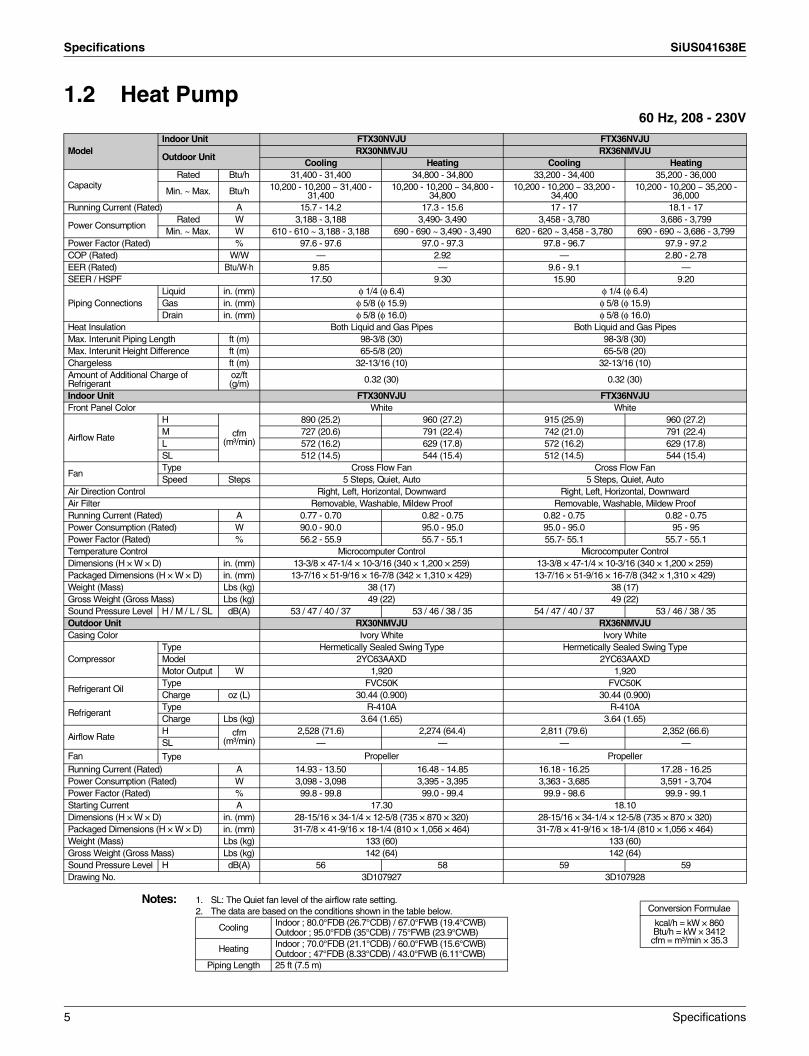
1.2 Heat Pump60 Hz, 208 - 230V
Notes: 1. SL: The Quiet fan level of the airflow rate setting.2. The data are based on the conditions shown in the table below.
ModelIndoor Unit FTX30NVJU FTX36NVJU
Outdoor UnitRX30NMVJU RX36NMVJU
Cooling Heating Cooling Heating
CapacityRated Btu/h 31,400 - 31,400 34,800 - 34,800 33,200 - 34,400 35,200 - 36,000
Min. ~ Max. Btu/h 10,200 - 10,200 ~ 31,400 - 31,400
10,200 - 10,200 ~ 34,800 - 34,800
10,200 - 10,200 ~ 33,200 - 34,400
10,200 - 10,200 ~ 35,200 - 36,000
Running Current (Rated) A 15.7 - 14.2 17.3 - 15.6 17 - 17 18.1 - 17
Power ConsumptionRated W 3,188 - 3,188 3,490- 3,490 3,458 - 3,780 3,686 - 3,799
Min. ~ Max. W 610 - 610 ~ 3,188 - 3,188 690 - 690 ~ 3,490 - 3,490 620 - 620 ~ 3,458 - 3,780 690 - 690 ~ 3,686 - 3,799Power Factor (Rated) % 97.6 - 97.6 97.0 - 97.3 97.8 - 96.7 97.9 - 97.2COP (Rated) W/W — 2.92 — 2.80 - 2.78EER (Rated) Btu/W·h 9.85 — 9.6 - 9.1 —SEER / HSPF 17.50 9.30 15.90 9.20
Piping ConnectionsLiquid in. (mm) φ 1/4 (φ 6.4) φ 1/4 (φ 6.4)Gas in. (mm) φ 5/8 (φ 15.9) φ 5/8 (φ 15.9)Drain in. (mm) φ 5/8 (φ 16.0) φ 5/8 (φ 16.0)
Heat Insulation Both Liquid and Gas Pipes Both Liquid and Gas PipesMax. Interunit Piping Length ft (m) 98-3/8 (30) 98-3/8 (30)Max. Interunit Height Difference ft (m) 65-5/8 (20) 65-5/8 (20)Chargeless ft (m) 32-13/16 (10) 32-13/16 (10)Amount of Additional Charge of Refrigerant
oz/ft(g/m) 0.32 (30) 0.32 (30)
Indoor Unit FTX30NVJU FTX36NVJUFront Panel Color White White
Airflow Rate
H
cfm(m³/min)
890 (25.2) 960 (27.2) 915 (25.9) 960 (27.2)M 727 (20.6) 791 (22.4) 742 (21.0) 791 (22.4)L 572 (16.2) 629 (17.8) 572 (16.2) 629 (17.8)SL 512 (14.5) 544 (15.4) 512 (14.5) 544 (15.4)
FanType Cross Flow Fan Cross Flow FanSpeed Steps 5 Steps, Quiet, Auto 5 Steps, Quiet, Auto
Air Direction Control Right, Left, Horizontal, Downward Right, Left, Horizontal, DownwardAir Filter Removable, Washable, Mildew Proof Removable, Washable, Mildew ProofRunning Current (Rated) A 0.77 - 0.70 0.82 - 0.75 0.82 - 0.75 0.82 - 0.75Power Consumption (Rated) W 90.0 - 90.0 95.0 - 95.0 95.0 - 95.0 95 - 95Power Factor (Rated) % 56.2 - 55.9 55.7 - 55.1 55.7- 55.1 55.7 - 55.1Temperature Control Microcomputer Control Microcomputer ControlDimensions (H × W × D) in. (mm) 13-3/8 × 47-1/4 × 10-3/16 (340 × 1,200 × 259) 13-3/8 × 47-1/4 × 10-3/16 (340 × 1,200 × 259)Packaged Dimensions (H × W × D) in. (mm) 13-7/16 × 51-9/16 × 16-7/8 (342 × 1,310 × 429) 13-7/16 × 51-9/16 × 16-7/8 (342 × 1,310 × 429)Weight (Mass) Lbs (kg) 38 (17) 38 (17)Gross Weight (Gross Mass) Lbs (kg) 49 (22) 49 (22)Sound Pressure Level H / M / L / SL dB(A) 53 / 47 / 40 / 37 53 / 46 / 38 / 35 54 / 47 / 40 / 37 53 / 46 / 38 / 35Outdoor Unit RX30NMVJU RX36NMVJUCasing Color Ivory White Ivory White
CompressorType Hermetically Sealed Swing Type Hermetically Sealed Swing TypeModel 2YC63AAXD 2YC63AAXDMotor Output W 1,920 1,920
Refrigerant OilType FVC50K FVC50KCharge oz (L) 30.44 (0.900) 30.44 (0.900)
RefrigerantType R-410A R-410ACharge Lbs (kg) 3.64 (1.65) 3.64 (1.65)
Airflow RateH cfm
(m³/min)2,528 (71.6) 2,274 (64.4) 2,811 (79.6) 2,352 (66.6)
SL — — — —Fan Type Propeller PropellerRunning Current (Rated) A 14.93 - 13.50 16.48 - 14.85 16.18 - 16.25 17.28 - 16.25Power Consumption (Rated) W 3,098 - 3,098 3,395 - 3,395 3,363 - 3,685 3,591 - 3,704Power Factor (Rated) % 99.8 - 99.8 99.0 - 99.4 99.9 - 98.6 99.9 - 99.1Starting Current A 17.30 18.10Dimensions (H × W × D) in. (mm) 28-15/16 × 34-1/4 × 12-5/8 (735 × 870 × 320) 28-15/16 × 34-1/4 × 12-5/8 (735 × 870 × 320)Packaged Dimensions (H × W × D) in. (mm) 31-7/8 × 41-9/16 × 18-1/4 (810 × 1,056 × 464) 31-7/8 × 41-9/16 × 18-1/4 (810 × 1,056 × 464)Weight (Mass) Lbs (kg) 133 (60) 133 (60)Gross Weight (Gross Mass) Lbs (kg) 142 (64) 142 (64)Sound Pressure Level H dB(A) 56 58 59 59Drawing No. 3D107927 3D107928
Conversion Formulae
kcal/h = kW × 860Btu/h = kW × 3412cfm = m³/min × 35.3
Cooling Indoor ; 80.0°FDB (26.7°CDB) / 67.0°FWB (19.4°CWB)Outdoor ; 95.0°FDB (35°CDB) / 75°FWB (23.9°CWB)
Heating Indoor ; 70.0°FDB (21.1°CDB) / 60.0°FWB (15.6°CWB)Outdoor ; 47°FDB (8.33°CDB) / 43.0°FWB (6.11°CWB)
Piping Length 25 ft (7.5 m)
5 Specifications

SiUS041638E
Printed Circuit Board Connector Wiring Diagram 6
Part 3Printed Circuit Board
Connector Wiring Diagram1. Indoor Unit...................................................................................................7
1.1 FTX30/36NVJU ............................................................................................ 7
2. Outdoor Unit................................................................................................92.1 RK(X)30/36NMVJU ...................................................................................... 9
Indoor Unit SiUS041638E
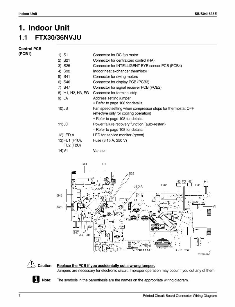
1. Indoor Unit1.1 FTX30/36NVJU
Control PCB (PCB1)
Caution Replace the PCB if you accidentally cut a wrong jumper.Jumpers are necessary for electronic circuit. Improper operation may occur if you cut any of them.
Note: The symbols in the parenthesis are the names on the appropriate wiring diagram.
1) S1 Connector for DC fan motor2) S21 Connector for centralized control (HA)3) S25 Connector for INTELLIGENT EYE sensor PCB (PCB4)4) S32 Indoor heat exchanger thermistor5) S41 Connector for swing motors6) S46 Connector for display PCB (PCB3)7) S47 Connector for signal receiver PCB (PCB2)8) H1, H2, H3, FG Connector for terminal strip9) JA Address setting jumper
∗ Refer to page 108 for details.10)JB Fan speed setting when compressor stops for thermostat OFF
(effective only for cooling operation)∗ Refer to page 108 for details.
11)JC Power failure recovery function (auto-restart)∗ Refer to page 108 for details.
12)LED A LED for service monitor (green)13)FU1 (F1U),
FU2 (F2U)Fuse (3.15 A, 250 V)
14)V1 Varistor
2P227881-8
FU1
V1
H1H2FGH3
LED A
S32
S1S41
S46
S25
S47
S21
JBJA
JC
FU2
7 Printed Circuit Board Connector Wiring Diagram
SiUS041638E Indoor Unit
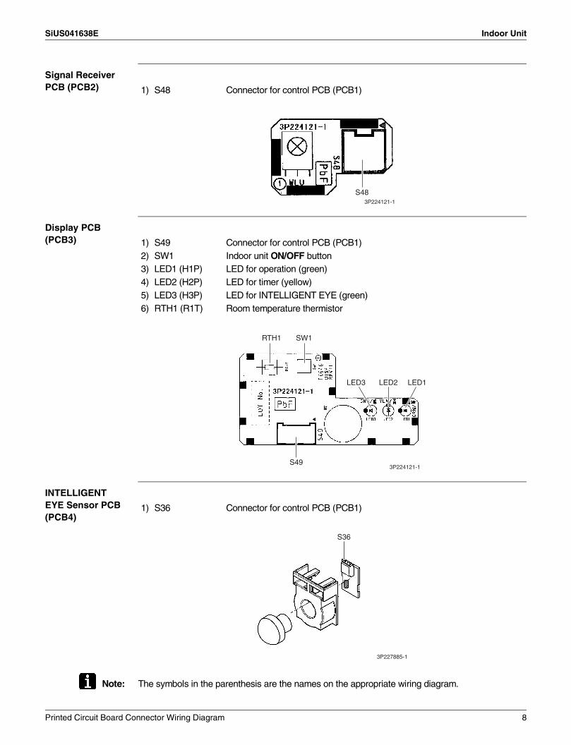
Signal Receiver PCB (PCB2)
Display PCB (PCB3)
INTELLIGENT EYE Sensor PCB (PCB4)
Note: The symbols in the parenthesis are the names on the appropriate wiring diagram.
1) S48 Connector for control PCB (PCB1)
3P224121-1
S48
1) S49 Connector for control PCB (PCB1)2) SW1 Indoor unit ON/OFF button3) LED1 (H1P) LED for operation (green)4) LED2 (H2P) LED for timer (yellow)5) LED3 (H3P) LED for INTELLIGENT EYE (green)6) RTH1 (R1T) Room temperature thermistor
3P224121-1
RTH1 SW1
LED3 LED2 LED1
S49
1) S36 Connector for control PCB (PCB1)
S36
3P227885-1
Printed Circuit Board Connector Wiring Diagram 8
Outdoor Unit SiUS041638E
2. Outdoor Unit2.1 RK(X)30/36NMVJU
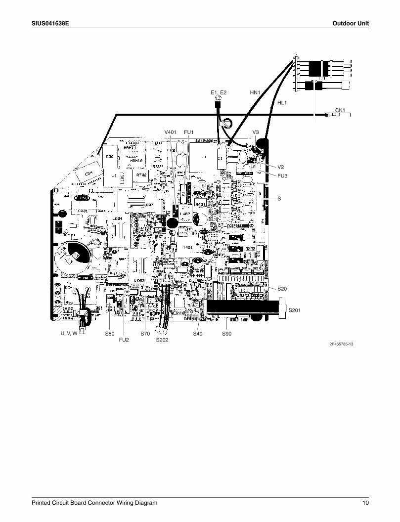
Main PCB (PCB1) 1) S Connector for terminal block (indoor - outdoor transmission)
2) S20 (white) Connector for electronic expansion valve coil3) S40 Connector for overload protector4) S70 Connector for DC fan motor5) S80 Connector for four way valve coil (heat pump models only)6) S90 Connector for thermistors
(outdoor temperature, outdoor heat exchanger, discharge pipe)7) S201, S202 Connector for service monitor PCB (PCB2)8) CK1 Connector for voltage endurance test9) HL1, HN1 Connector for terminal block (power supply)10) E1, E2 Connector for ground wire11) U, V, W Connector for compressor12) FU1, FU2 Fuse (3.15 A, 250 V)13) FU3 Fuse (30 A, 250 V)14) V2, V3, V401 Varistor
9 Printed Circuit Board Connector Wiring Diagram
SiUS041638E Outdoor Unit
V401
E1, E2
FU1 V3
V2
FU3
HN1
HL1CK1
S20
S90
S201
S
S70S202
U, V, WFU2
S80 S40
2P455785-13
Printed Circuit Board Connector Wiring Diagram 10

Outdoor Unit SiUS041638E
Service Monitor PCB (PCB2)
SW1 ~ SW4 and LED1 ~ LED5 do not work.
1) S501, S502 Connector for main PCB (PCB1)2) LED A LED for service monitor (green)3) SW5-3 Switch for facility setting
∗ Refer to page 109 for details.4) SW6-2 Switch for facility setting
∗ Refer to page 109 for details.
3P346711-10
S502SW6-2SW5-3
LED A S501
11 Printed Circuit Board Connector Wiring Diagram
SiUS041638E
Functions and Control 12
Part 4Functions and Control
1. Main Functions..........................................................................................131.1 Temperature Control .................................................................................. 131.2 Frequency Principle.................................................................................... 131.3 Airflow Direction Control............................................................................. 151.4 Fan Speed Control for Indoor Unit ............................................................. 161.5 Program Dry Operation .............................................................................. 171.6 Automatic Operation................................................................................... 181.7 Thermostat Control..................................................................................... 191.8 NIGHT SET Mode ...................................................................................... 201.9 ECONO Operation ..................................................................................... 201.10 INTELLIGENT EYE Operation ................................................................... 211.11 POWERFUL Operation .............................................................................. 221.12 Clock Setting .............................................................................................. 231.13 WEEKLY TIMER Operation ....................................................................... 241.14 Other Functions.......................................................................................... 30
2. Thermistor Functions ................................................................................313. Control Specification .................................................................................33
3.1 Mode Hierarchy .......................................................................................... 333.2 Frequency Control...................................................................................... 343.3 Controls at Mode Changing/Start-up.......................................................... 363.4 Discharge Pipe Temperature Control......................................................... 383.5 Input Current Control.................................................................................. 393.6 Freeze-up Protection Control ..................................................................... 403.7 Heating Peak-cut Control ........................................................................... 403.8 Outdoor Fan Control................................................................................... 413.9 Liquid Compression Protection Function.................................................... 413.10 Defrost Control ........................................................................................... 423.11 Electronic Expansion Valve Control ........................................................... 433.12 Malfunctions ............................................................................................... 46

Main Functions SiUS041638E
1. Main Functions1.1 Temperature Control
Definitions of Temperatures
The definitions of temperatures are classified as following.
Room temperature: temperature of lower part of the roomSet temperature: temperature set by remote controllerRoom thermistor temperature: temperature detected by room temperature thermistorTarget temperature: temperature determined by microcomputer
Temperature Control
The temperature of the room is detected by the room temperature thermistor. However, there is a difference between the temperature detected by room temperature thermistor and the temperature of lower part of the room, depending on the type of the indoor unit or installation condition. Practically, the temperature control is done by the target temperature appropriately adjusted for the indoor unit and the temperature detected by room temperature thermistor.
1.2 Frequency Principle
Control Parameters
The frequency of the compressor is controlled by the following 2 parameters:The load condition of the operating indoor unitThe difference between the room thermistor temperature and the target temperature
The target frequency is adapted by additional parameters in the following cases:Frequency restrictionsInitial settingsForced cooling operation
Inverter Principle To regulate the capacity, a frequency control is needed. The inverter makes it possible to control the rotation speed of the compressor. The following table explains the inverter principle:
Target temperature
Set temperature
Room temperature
Room thermistor temperature
(R12321)
Phase Description
1 The supplied AC power source is converted into the DC power source for the present.
2 The DC power source is reconverted into the three phase AC power source with variable frequency.
When the frequency increases, the rotation speed of the compressor increases resulting in an increase of refrigerant circulation. This leads to a larger amount of heat exchange per unit.When the frequency decreases, the rotation speed of the compressor decreases resulting in a decrease of refrigerant circulation. This leads to a smaller amount of heat exchange per unit.
13 Functions and Control

SiUS041638E Main Functions
The following drawing shows a schematic view of the inverter principle:
Inverter Features The inverter provides the following features:The regulating capacity can be changed according to the changes in the outdoor temperature and cooling/heating load.Quick heating and quick coolingThe rotation speed of the compressor is increased when starting the heating (or cooling). This enables to reach the set temperature quickly.Even during extreme cold weather, high capacity is achieved. It is maintained even when the outdoor temperature is 2°C (35.6 °F).Comfortable air conditioning A fine adjustment is integrated to keep the room temperature constant.Energy saving heating and coolingOnce the set temperature is reached, the energy saving operation enables to maintain the room temperature at low power.
Frequency Limits The following functions regulate the minimum and maximum frequency:
Forced Cooling Operation
Refer to page 105 for details.
Refrigerant circulation rate (high)
high f
low f
freq=variable
Refrigerant circulation rate (low)
high speed
low speed
(R2812)
Amount of heat exchanged air (large)
freq= constant
50 Hz 60 Hz
capacity= variable
Amount of heat exchanged air (small)
AC
po
wer
DC
po
wer
Amount of heat exchanged air (large)
Amount of heat exchanged air (small)
Frequency Functions
Low Four way valve operation compensation. Refer to page 36.
High Compressor protection function. Refer to page 37.Discharge pipe temperature control. Refer to page 38.Input current control. Refer to page 39.Freeze-up protection control. Refer to page 40.Heating peak-cut control. Refer to page 40.Defrost control. Refer to page 42.
Functions and Control 14

Main Functions SiUS041638E
1.3 Airflow Direction Control
Power-Airflow Dual Flaps
The large flap sends a large volume of air downward to the floor and provides an optimum control in cooling, dry, and heating operation.
Cooling/DryDuring cooling or dry operation, the flap retracts into the indoor unit. Then, cool air can be blown far and distributed all over the room.
HeatingDuring heating operation, the large flap directs airflow downward to spread the warm air to the entire room.
Wide-Angle Louvers
The louvers, made of elastic synthetic resin, provide a wide range of airflow that guarantees comfortable air distribution.
Auto-Swing The following table explains the auto-swing process for cooling, dry, heating, and fan:
3-D Airflow Alternative repetition of vertical and horizontal swing motions enables uniform air-conditioning of the entire room.
When the horizontal swing and vertical swing are both set to automatic operation, the airflow becomes 3-D airflow. The horizontal and vertical swing motions are alternated and the airflow direction changes in the order shown in the following diagram.
(1) The louvers move from the right to the left.(2) The flaps move downward.(3) The louvers move from the left to the right.(4) The flaps move upward.
COMFORT AIRFLOW Operation
The airflow direction is upward while in cooling and dry operation, and downward while in heating operation. This function prevents cold or warm air from blowing directly on the occupants in the room.
When COMFORT AIRFLOW operation is set, or the combination use of COMFORT AIRFLOW operation and INTELLIGENT EYE operation is set, the airflow rate will be set to AUTO.If the up and down airflow direction is selected, COMFORT AIRFLOW operation will be canceled.Priority is given to the function of whichever button is pressed last.
Flap (up and down) Louver (right and left)Cooling/Dry Heating Fan
(R9303)
60˚50˚25˚
15˚
(R9304)70˚
40˚ 75˚
30˚
(R9305)
75˚
15˚
25˚70˚
(R9306)
45˚ 45˚
(R19554)
(2)(4)
(3)
(1)
15 Functions and Control
SiUS041638E Main Functions
1.4 Fan Speed Control for Indoor Unit
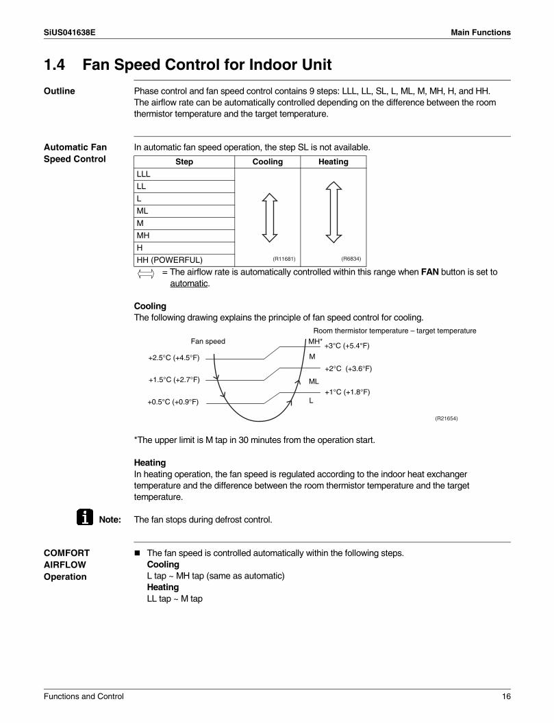
Outline Phase control and fan speed control contains 9 steps: LLL, LL, SL, L, ML, M, MH, H, and HH.The airflow rate can be automatically controlled depending on the difference between the room thermistor temperature and the target temperature.
Automatic Fan Speed Control
In automatic fan speed operation, the step SL is not available.
= The airflow rate is automatically controlled within this range when FAN button is set to automatic.
CoolingThe following drawing explains the principle of fan speed control for cooling.
*The upper limit is M tap in 30 minutes from the operation start.
HeatingIn heating operation, the fan speed is regulated according to the indoor heat exchanger temperature and the difference between the room thermistor temperature and the target temperature.
Note: The fan stops during defrost control.
COMFORT AIRFLOW Operation
The fan speed is controlled automatically within the following steps.CoolingL tap ~ MH tap (same as automatic)HeatingLL tap ~ M tap
Step Cooling Heating
LLL
LL
L
ML
M
MH
H
HH (POWERFUL) (R11681) (R6834)
(R21654)
Fan speed
+2.5°C (+4.5°F)
+1.5°C (+2.7°F)
+0.5°C (+0.9°F)
MH*
M
ML
L
+3°C (+5.4°F)
+2°C (+3.6°F)
+1°C (+1.8°F)
Room thermistor temperature – target temperature
Functions and Control 16

Main Functions SiUS041638E
1.5 Program Dry Operation
Outline Program dry operation removes humidity while preventing the room temperature from lowering.Since the microcomputer controls both the temperature and airflow rate, the temperature adjustment and FAN setting buttons are inoperable.
Details The microcomputer automatically sets the temperature and airflow rate. The difference between the room thermistor temperature at start-up and the target temperature is divided into two zones. Then, the unit operates in an appropriate capacity for each zone to maintain the temperature and humidity at a comfortable level.
Thermostat turns on also when the room temperature is in the zone B for 10 minutes.
Room thermistor temperature at start-up
Target temperatureX
Thermostat OFF pointY
Thermostat ON pointZ
24°C or more (75.2°F or more) Room thermistor
temperature at start-up
X – 2.5°C (X – 4.5°F)
X – 0.5°C (X – 0.9°F)
18 ~ 23.5°C (64.4 ~ 74.3°F)
X – 2.0°C (X – 3.6°F)
X – 0.5°C (X – 0.9°F)
17.5°C or less (63.5°F or less)
18°C (64.4°F)
X – 2.0°C (X – 3.6°F)
X – 0.5°C = 17.5°C(X – 0.9°F = 63.5°F)
Zone A = Thermostat OFF
Target temperature X
Zone B
Room temperature Room temperature
Zone C = Thermostat ON
Y = X – 2.5°C (4.5°F)or
Y = X – 2.0°C (3.6°F)
Z = X – 0.5°C (0.9°F)
X – 1.0°C (1.8°F)
(R24029)
17 Functions and Control

SiUS041638E Main Functions
1.6 Automatic Operation
Outline Automatic Cooling/Heating FunctionWhen the automatic operation is selected with the remote controller, the microcomputer automatically determines the operation mode as cooling or heating according to the room temperature and the set temperature at start-up.The unit automatically switches the operation mode to maintain the room temperature at the set temperature.
Details Ts: set temperature (set by remote controller)Tt: target temperature (determined by microcomputer)Tr: room thermistor temperature (detected by room temperature thermistor)C: correction value
1. The set temperature (Ts) determines the target temperature (Tt). (Ts = 18 ~ 30°C, 64 ~ 86°F).
2. The target temperature (Tt) is calculated as:Tt = Ts + C
where C is the correction value.C = 0°C (0°F)
3. Thermostat ON/OFF point and operation mode switching point are as follows.Tr means the room thermistor temperature.(1) Heating → Cooling switching point:
Tr ≥ Tt + 3.0°C (+5.4°F)(2) Cooling → Heating switching point:
Tr < Tt – 2.5°C (–4.5°F)(3) Thermostat ON/OFF point is the same as the ON/OFF point of cooling or heating operation.
4. During initial operationTr ≥ Ts : Cooling operationTr < Ts : Heating operation
Ex: When the target temperature is 25°C (77°F)Cooling → 23°C (73.4°F): Thermostat OFF → 22°C (71.6°F): Switch to heatingHeating → 27°C (80.6°F): Thermostat OFF → 28°C (82.4°F): Switch to cooling
Target temperature + 3.0˚C (+5.4˚F)
Heating Operation
Target temperature – 3.0˚C (–5.4˚F)
Cooling Operation
(R24627)
Target temperature – 2.0˚C (–3.6˚F) = Thermostat OFF
Target temperature + 2.0˚C (+3.6˚F) = Thermostat OFF
Functions and Control 18
Main Functions SiUS041638E
1.7 Thermostat Control
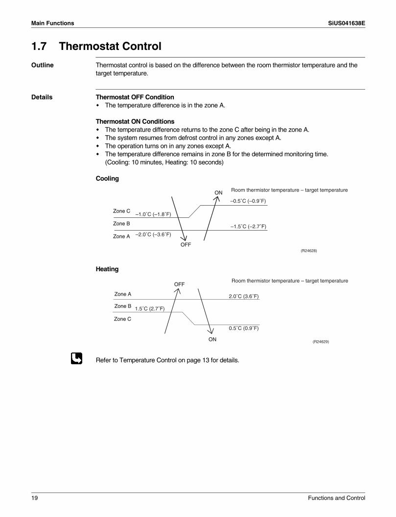
Outline Thermostat control is based on the difference between the room thermistor temperature and the target temperature.
Details Thermostat OFF ConditionThe temperature difference is in the zone A.
Thermostat ON ConditionsThe temperature difference returns to the zone C after being in the zone A.The system resumes from defrost control in any zones except A.The operation turns on in any zones except A.The temperature difference remains in zone B for the determined monitoring time.(Cooling: 10 minutes, Heating: 10 seconds)
Cooling
Heating
Refer to Temperature Control on page 13 for details.
Zone B
Zone A
OFF
ON
Zone C
Room thermistor temperature – target temperature
–1.0˚C (–1.8˚F)
–2.0˚C (–3.6˚F)
(R24628)
–0.5˚C (–0.9˚F)
–1.5˚C (–2.7˚F)
Zone BZone B
Zone AZone A
OFFOFF
ONON
Zone CZone C
2.0˚C (3.6˚F)
0.5˚C (0.9˚F)
1.5˚C (2.7˚F)
Room thermistor temperature – target temperature
(R24629)
19 Functions and Control
SiUS041638E Main Functions
1.8 NIGHT SET Mode
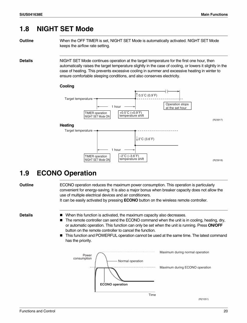
Outline When the OFF TIMER is set, NIGHT SET Mode is automatically activated. NIGHT SET Mode keeps the airflow rate setting.
Details NIGHT SET Mode continues operation at the target temperature for the first one hour, then automatically raises the target temperature slightly in the case of cooling, or lowers it slightly in the case of heating. This prevents excessive cooling in summer and excessive heating in winter to ensure comfortable sleeping conditions, and also conserves electricity.
Cooling
Heating
1.9 ECONO Operation
Outline ECONO operation reduces the maximum power consumption. This operation is particularly convenient for energy-saving. It is also a major bonus when breaker capacity does not allow the use of multiple electrical devices and air conditioners.It can be easily activated by pressing ECONO button on the wireless remote controller.
Details When this function is activated, the maximum capacity also decreases.The remote controller can send the ECONO command when the unit is in cooling, heating, dry, or automatic operation. This function can only be set when the unit is running. Press ON/OFF button on the remote controller to cancel the function.This function and POWERFUL operation cannot be used at the same time. The latest command has the priority.
(R23917)
Target temperature
+0.5˚C (+0.9˚F) temperature shift
Operation stops at the set hour
0.5˚C (0.9˚F)
1 hour
TIMER operation NIGHT SET Mode ON
Target temperature
–2˚C (–3.6˚F) temperature shift
1 hour
2˚C (3.6˚F)
(R23918)
TIMER operation NIGHT SET Mode ON
ECONO operation
(R21051)
Normal operation
Maximum during normal operation
Maximum during ECONO operation
Time
Power consumption
Functions and Control 20
Main Functions SiUS041638E
1.10 INTELLIGENT EYE Operation
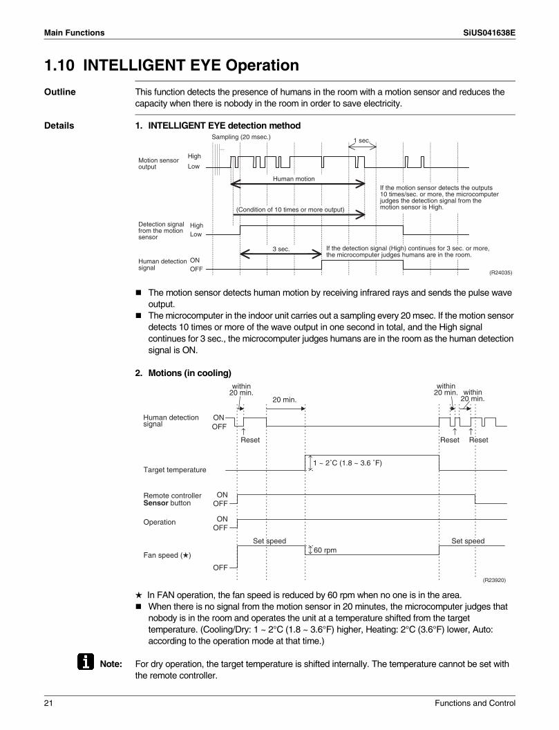
Outline This function detects the presence of humans in the room with a motion sensor and reduces the capacity when there is nobody in the room in order to save electricity.
Details 1. INTELLIGENT EYE detection method
The motion sensor detects human motion by receiving infrared rays and sends the pulse wave output.The microcomputer in the indoor unit carries out a sampling every 20 msec. If the motion sensor detects 10 times or more of the wave output in one second in total, and the High signal continues for 3 sec., the microcomputer judges humans are in the room as the human detection signal is ON.
2. Motions (in cooling)
In FAN operation, the fan speed is reduced by 60 rpm when no one is in the area.When there is no signal from the motion sensor in 20 minutes, the microcomputer judges that nobody is in the room and operates the unit at a temperature shifted from the target temperature. (Cooling/Dry: 1 ~ 2°C (1.8 ~ 3.6°F) higher, Heating: 2°C (3.6°F) lower, Auto: according to the operation mode at that time.)
Note: For dry operation, the target temperature is shifted internally. The temperature cannot be set with the remote controller.
1 sec.Sampling (20 msec.)
High
Low
ONOFF
HighLow
(R24035)
(Condition of 10 times or more output)
Human motion
3 sec. If the detection signal (High) continues for 3 sec. or more, the microcomputer judges humans are in the room.
Detection signal from the motion sensor
Human detection signal
Motion sensor output
If the motion sensor detects the outputs 10 times/sec. or more, the microcomputer judges the detection signal from the motion sensor is High.
ONOFF
Reset Reset Reset
20 min.
1 ~ 2˚C (1.8 ~ 3.6 ˚F)
ONOFF
ONOFF
Operation
OFF
Fan speed ( )
Set speed Set speed
Target temperature
(R23920)
Remote controller Sensor button
Human detection signal
↑ ↑
60 rpm
↑
within 20 min.
within 20 min. within
20 min.
21 Functions and Control
SiUS041638E Main Functions
1.11 POWERFUL Operation
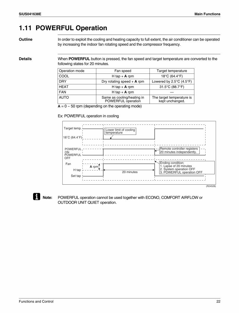
Outline In order to exploit the cooling and heating capacity to full extent, the air conditioner can be operated by increasing the indoor fan rotating speed and the compressor frequency.
Details When POWERFUL button is pressed, the fan speed and target temperature are converted to the following states for 20 minutes.
A = 0 ~ 50 rpm (depending on the operating mode)
Ex: POWERFUL operation in cooling
Note: POWERFUL operation cannot be used together with ECONO, COMFORT AIRFLOW or OUTDOOR UNIT QUIET operation.
Operation mode Fan speed Target temperature
COOL H tap + A rpm 18°C (64.4°F)
DRY Dry rotating speed + A rpm Lowered by 2.5°C (4.5°F)
HEAT H tap + A rpm 31.5°C (88.7°F)
FAN H tap + A rpm —
AUTO Same as cooling/heating in POWERFUL operation
The target temperature is kept unchanged.
(R24528)
Target temp.
FanA rpm
H tap
Set tap20 minutes
Lower limit of cooling temperature
Remote controller registers 20 minutes independently.
POWERFUL ONPOWERFUL OFF
Ending condition:1. Lapse of 20 minutes2. System operation OFF3. POWERFUL operation OFF
18˚C (64.4˚F)
Functions and Control 22
Main Functions SiUS041638E
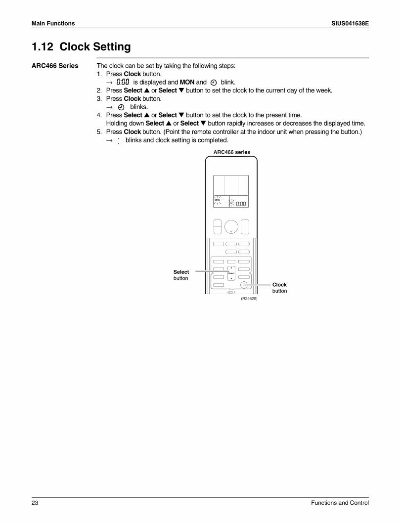
1.12 Clock Setting
ARC466 Series The clock can be set by taking the following steps:1. Press Clock button.
→ is displayed and MON and blink.2. Press Select or Select button to set the clock to the current day of the week.3. Press Clock button.
→ blinks.4. Press Select or Select button to set the clock to the present time.
Holding down Select or Select button rapidly increases or decreases the displayed time.5. Press Clock button. (Point the remote controller at the indoor unit when pressing the button.)
→ blinks and clock setting is completed.
(R24529)
0:00
Select button
Clock button
ARC466 series
23 Functions and Control

SiUS041638E Main Functions
1.13 WEEKLY TIMER Operation
Outline Up to 4 timer settings can be saved for each day of the week (up to 28 settings in total).The 3 items: ON/OFF, temperature, and time can be set.
Details
ON ON OFFOFF
ON ONOFFOFF
Setting example of the WEEKLY TIMERThe same timer settings are used from Monday through Friday, while different timer settings are used for the weekend.
[Monday] Make timer settings for programs 1-4.
6:00 8:30 17:30 22:00
77˚F (25˚C) 81˚F (27˚C)
program 1 program 2 program 3 program 4ON OFF ON OFF
6:00 8:30 17:30 22:00
77˚F (25˚C) 81˚F (27˚C)
program 1 program 2 program 3 program 4ON OFF ON OFF
[Saturday] No timer settings
[Sunday] Make timer settings for programs 1-4.
8:00 10:00 19:00 21:00
81˚F (27˚C) 81˚F (27˚C)77˚F (25˚C)
ON OFF OFF ONprogram 1 program 2 program 3 program 4
[Tuesday] to
[Friday]
Use the copy mode to make settings for Tuesday to Friday, because these settings are the same as those for Monday.
• Up to 4 reservations per day and 28 reservations per week can be set using the WEEKLY TIMER. The effective use of the copy mode simplifies timer programming.
• The use of ON-ON-ON-ON settings, for example, makes it possible to schedule operating mode and set temperature changes. Furthermore, by using OFF-OFF-OFF-OFF settings, only the turn off time of each day can be set. This will turn off the air conditioner automatically if you forget to turn it off.
Functions and Control 24
Main Functions SiUS041638E
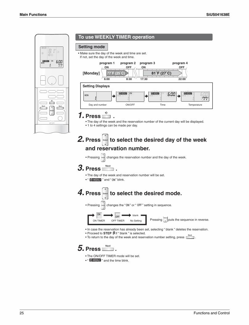
To use WEEKLY TIMER operation
Setting mode• Make sure the day of the week and time are set.
If not, set the day of the week and time.
6:00 8:30 17:30 22:00
77˚F (25˚C) 81˚F (27˚C)
program 1 program 2 program 3 program 4ON OFF ON OFF
[Monday]
Setting Displays
Day and number ON/OFF Time Temperature
1. Press .• The day of the week and the reservation number of the current day will be displayed.• 1 to 4 settings can be made per day.
• Pressing changes the reservation number and the day of the week.
3. Press .• The day of the week and reservation number will be set.• “ ” and “ ” blink.
4. Press to select the desired mode.
• Pressing changes the “ ” or “ ” setting in sequence.
ON TIMER OFF TIMER
blank
No Setting Pressing puts the sequence in reverse.
5. Press .
2. Press to select the desired day of the week
and reservation number.
• In case the reservation has already been set, selecting “ blank ” deletes the reservation.• Proceed to STEP 9 if “ blank ” is selected.• To return to the day of the week and reservation number setting, press .
• The ON/OFF TIMER mode will be set.• “ ” and the time blink.
25 Functions and Control
SiUS041638E Main Functions
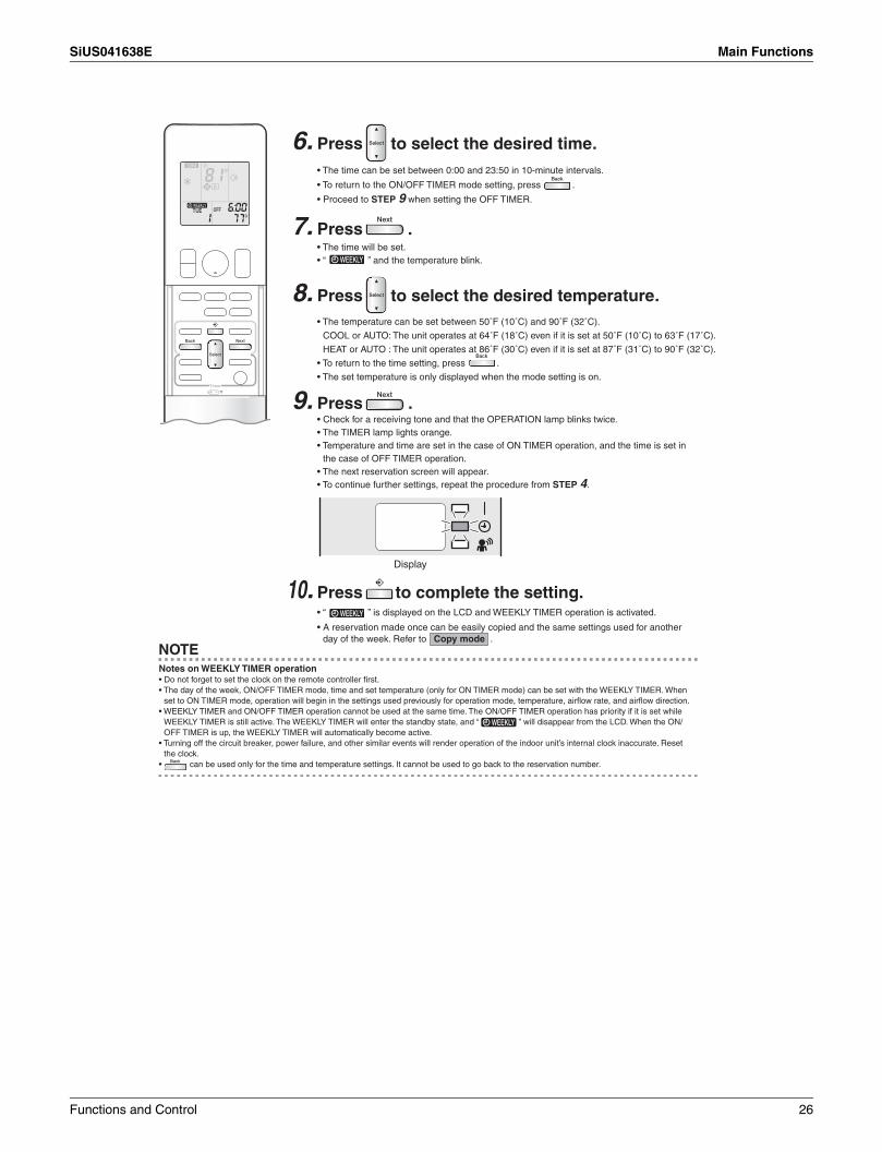
6. Press to select the desired time.
7. Press .
8. Press to select the desired temperature.
9. Press .
10. Press to complete the setting.
NOTE
• The time can be set between 0:00 and 23:50 in 10-minute intervals.
• To return to the ON/OFF TIMER mode setting, press .
• Proceed to STEP 9 when setting the OFF TIMER.
• The time will be set.• “ ” and the temperature blink.
• The temperature can be set between 50˚F (10˚C) and 90˚F (32˚C).
COOL or AUTO: The unit operates at 64˚F (18˚C) even if it is set at 50˚F (10˚C) to 63˚F (17˚C).
HEAT or AUTO : The unit operates at 86˚F (30˚C) even if it is set at 87˚F (31˚C) to 90˚F (32˚C).
• To return to the time setting, press .
• The set temperature is only displayed when the mode setting is on.
• Check for a receiving tone and that the OPERATION lamp blinks twice.• The TIMER lamp lights orange.• Temperature and time are set in the case of ON TIMER operation, and the time is set in
the case of OFF TIMER operation.• The next reservation screen will appear.• To continue further settings, repeat the procedure from STEP 4.
• “ ” is displayed on the LCD and WEEKLY TIMER operation is activated.
• A reservation made once can be easily copied and the same settings used for another day of the week. Refer to Copy mode .
Notes on WEEKLY TIMER operation• Do not forget to set the clock on the remote controller first.• The day of the week, ON/OFF TIMER mode, time and set temperature (only for ON TIMER mode) can be set with the WEEKLY TIMER. When
set to ON TIMER mode, operation will begin in the settings used previously for operation mode, temperature, airflow rate, and airflow direction.• WEEKLY TIMER and ON/OFF TIMER operation cannot be used at the same time. The ON/OFF TIMER operation has priority if it is set while
WEEKLY TIMER is still active. The WEEKLY TIMER will enter the standby state, and “ ” will disappear from the LCD. When the ON/ OFF TIMER is up, the WEEKLY TIMER will automatically become active.
• Turning off the circuit breaker, power failure, and other similar events will render operation of the indoor unit’s internal clock inaccurate. Reset the clock.
• can be used only for the time and temperature settings. It cannot be used to go back to the reservation number.
Display
Functions and Control 26

Main Functions SiUS041638E
Copy mode
6:00 8:30 17:30 22:00
77˚F (25˚C) 81˚F (27˚C)
6:00 8:30 17:30 22:00
77˚F (25˚C) 81˚F (27˚C)
COPY
program 1 program 2 program 3 program 4ON OFF ON OFF
[Monday]
program 1 program 2 program 3 program 4ON OFF ON OFF
Setting Displays
Confirmation Copy Paste Normal
1. Press .
2. Press to confirm the day of the week to be copied.
3. Press .
4. Press to select the destination day of the week.
5. Press .
6. Press to complete the setting.
NOTE
[Tuesday] to
[Friday]
• A reservation made once can be copied to another day of the week. The whole reservation of the selected day of the week will be copied.
• The whole reservation of the selected day of the week will be copied.
• Check for a receiving tone and that the OPERATION lamp blinks twice.• The reservation will be copied to the selected day of the week. The whole reservation of
the selected day of the week will be copied.• To continue copying the settings to other days of the week, repeat STEP 4 and STEP 5.
• “ ” is displayed on the LCD and WEEKLY TIMER operation is activated.
Note on COPY MODE• The entire reservation of the source day of the week is copied in the copy mode.
In the case of making a reservation change for any day of the week individually after copying the content of weekly reservations, press and change the settings in the steps of Setting mode .
27 Functions and Control
SiUS041638E Main Functions
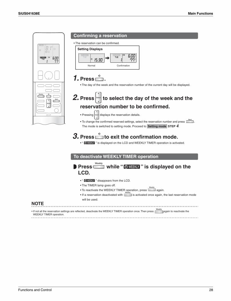
Confirming a reservation
Setting Displays
Normal Confirmation
1. Press .
3. Press to exit the confirmation mode.
To deactivate WEEKLY TIMER operation
NOTE
2.
• The reservation can be confirmed.
• The day of the week and the reservation number of the current day will be displayed.
• Pressing displays the reservation details.
• To change the confirmed reserved settings, select the reservation number and press .
The mode is switched to setting mode. Proceed to Setting mode STEP 4.
• “ ” is displayed on the LCD and WEEKLY TIMER operation is activated.
• “ ” disappears from the LCD.
• The TIMER lamp goes off.
• To reactivate the WEEKLY TIMER operation, press again.
• If a reservation deactivated with is activated once again, the last reservation mode
will be used.
Press to select the day of the week and the
reservation number to be confirmed.
Press while “ ” is displayed on the LCD.
• If not all the reservation settings are reflected, deactivate the WEEKLY TIMER operation once. Then press again to reactivate the WEEKLY TIMER operation.
Functions and Control 28

Main Functions SiUS041638E
To delete reservations
An individual reservation
1. Press .• The day of the week and the reservation number will be displayed.
3. Press .
4. Press until no icon is displayed.
ON TIMER OFF TIMER
blank
No Setting Pressing puts the sequence in reverse.
5. Press .
6. Press .• If there are still other reservations, WEEKLY TIMER operation will be activated.
Reservations for each day of the week
1. Press .• The day of the week and the reservation number will be displayed.
2. Press to select the day of the week to be deleted.
3. Hold for about 5 seconds.
4. Press .• If there are still other reservations, WEEKLY TIMER operation will be activated.
All reservations
Hold for about 5 seconds with the normal display.
2. Press to select the day of the week and the reservation number to be deleted.
• “ ” and “ ” or “ ” blink.
• Pressing changes the ON/OFF TIMER mode in sequence.
• Selecting “blank” will cancel any reservation you may have.
• This function can be used for deleting reservations for each day of the week.• It can be used while confirming or setting reservations.
• Check for a receiving tone and that the OPERATION lamp blinks twice.• “ ” disappears from the LCD.• The TIMER lamp goes off.• All reservations will be deleted.• This operation is not functional while the WEEKLY TIMER setting screen is displayed.
• The selected reservation will be deleted.• Check for a receiving tone and that the OPERATION lamp blinks twice.
• Check for a receiving tone and that the OPERATION lamp blinks twice.• The reservation of the selected day of the week will be deleted.
29 Functions and Control

SiUS041638E Main Functions
1.14 Other Functions1.14.1 Hot-Start Function
In order to prevent the cold air blast that normally occurs when heating operation starts, the temperature of the indoor heat exchanger is detected, and the airflow is either stopped or significantly weakened resulting in comfortable heating.
Note: The cold air blast is prevented using similar control when defrost control starts or when the thermostat is turned ON.
1.14.2 Signal Receiving SignWhen the indoor unit receives a signal from the remote controller, the unit emits a signal receiving sound and the operation lamp blinks.
1.14.3 Indoor Unit ON/OFF ButtonON/OFF button is provided on the display of the unit.
Press ON/OFF button once to start operation. Press once again to stop it.ON/OFF button is useful when the remote controller is missing or the battery has run out.
Forced cooling operationForced cooling operation can be started by pressing ON/OFF button for 5 to 9 seconds while the unit is not operating. Forced cooling operation is not started if ON/OFF button is pressed for 10 seconds or more.Refer to page 105 for details.
1.14.4 Auto-restart FunctionIf a power failure (even a momentary one) occurs during the operation, the system restarts automatically in the same conditions as before when the power supply is restored to the conditions prior to the power failure.
Note: It takes 3 minutes to restart the operation because the 3-minute standby function is activated.
Mode Temperature setting Airflow rateCooling Only COOL 22°C (72°F) AutomaticHeat Pump AUTO 25°C (77°F) Automatic
ON/OFF button (R20396)
Functions and Control 30
Thermistor Functions SiUS041638E
2. Thermistor Functions
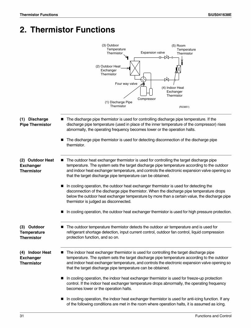
(1) Discharge Pipe Thermistor
The discharge pipe thermistor is used for controlling discharge pipe temperature. If the discharge pipe temperature (used in place of the inner temperature of the compressor) rises abnormally, the operating frequency becomes lower or the operation halts.
The discharge pipe thermistor is used for detecting disconnection of the discharge pipe thermistor.
(2) Outdoor Heat Exchanger Thermistor
The outdoor heat exchanger thermistor is used for controlling the target discharge pipe temperature. The system sets the target discharge pipe temperature according to the outdoor and indoor heat exchanger temperature, and controls the electronic expansion valve opening so that the target discharge pipe temperature can be obtained.
In cooling operation, the outdoor heat exchanger thermistor is used for detecting the disconnection of the discharge pipe thermistor. When the discharge pipe temperature drops below the outdoor heat exchanger temperature by more than a certain value, the discharge pipe thermistor is judged as disconnected.
In cooling operation, the outdoor heat exchanger thermistor is used for high pressure protection.
(3) Outdoor Temperature Thermistor
The outdoor temperature thermistor detects the outdoor air temperature and is used for refrigerant shortage detection, input current control, outdoor fan control, liquid compression protection function, and so on.
(4) Indoor Heat Exchanger Thermistor
The indoor heat exchanger thermistor is used for controlling the target discharge pipe temperature. The system sets the target discharge pipe temperature according to the outdoor and indoor heat exchanger temperature, and controls the electronic expansion valve opening so that the target discharge pipe temperature can be obtained.
In cooling operation, the indoor heat exchanger thermistor is used for freeze-up protection control. If the indoor heat exchanger temperature drops abnormally, the operating frequency becomes lower or the operation halts.
In cooling operation, the indoor heat exchanger thermistor is used for anti-icing function. If any of the following conditions are met in the room where operation halts, it is assumed as icing.
Four way valve
Compressor
(R23851)
Expansion valve
(2) Outdoor Heat Exchanger Thermistor
(3) Outdoor Temperature Thermistor
(5) Room Temperature Thermistor
(1) Discharge Pipe Thermistor
(4) Indoor Heat Exchanger Thermistor
31 Functions and Control
SiUS041638E Thermistor Functions
The conditions areTc ≤ – 1° CTa – Tc ≥ 10° Cwhere Ta is the room temperature and Tc is the indoor heat exchanger temperature.
In heating operation, the indoor heat exchanger thermistor is used for heating peak-cut control. If the indoor heat exchanger temperature rises abnormally, the operating frequency becomes lower or the operation halts.
In heating operation, the indoor heat exchanger thermistor is used for detecting the disconnection of the discharge pipe thermistor. When the discharge pipe temperature drops below the highest indoor heat exchanger temperature by more than a certain value, the discharge pipe thermistor is judged as disconnected.
When only one indoor unit is operating, the indoor heat exchanger thermistor is used for subcooling control. The actual subcool is calculated with the liquid pipe temperature and the indoor heat exchanger temperature. The system controls the electronic expansion valve openings to obtain the target subcool.
(5) Room Temperature Thermistor
The room temperature thermistor detects the room air temperature and is used for controlling the room air temperature.
Functions and Control 32

Control Specification SiUS041638E
3. Control Specification3.1 Mode Hierarchy
Outline The air conditioner control has normal operation mode, forced operation mode, and power transistor test mode for installation and servicing.
Details Cooling Only Model
Heat Pump Model
Note: Unless specified otherwise, dry operation command is regarded as cooling operation.
(R19505)
Air conditioner control mode
Forced operation mode
Forced cooling operation (for pump down operation)
Power transistor test mode
Normal operation mode
Fan
Cooling (includes drying)
Stop (indoor unit: OFF)
Preheating operation
Discharging from capacitor
Stop
Air conditioner control mode
Forced operation mode
Forced cooling operation (for pump down operation)
Power transistor test mode
Normal operation mode
Fan
Cooling (includes drying)
Heating
Heating
Defrosting
Stop (indoor unit: OFF)
Preheating operation
Discharging from capacitor
Stop
(R19522)
33 Functions and Control
SiUS041638E Control Specification
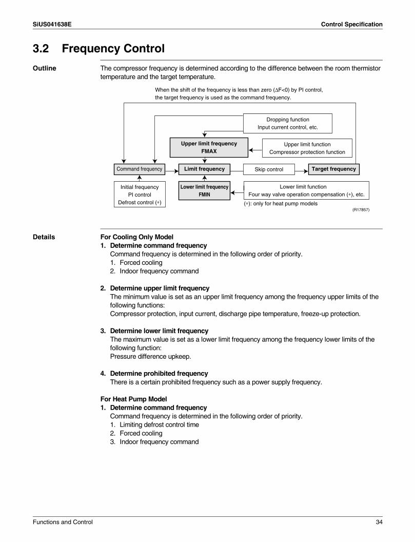
3.2 Frequency Control
Outline The compressor frequency is determined according to the difference between the room thermistor temperature and the target temperature.
Details For Cooling Only Model1. Determine command frequency
Command frequency is determined in the following order of priority.1. Forced cooling2. Indoor frequency command
2. Determine upper limit frequencyThe minimum value is set as an upper limit frequency among the frequency upper limits of the following functions: Compressor protection, input current, discharge pipe temperature, freeze-up protection.
3. Determine lower limit frequencyThe maximum value is set as a lower limit frequency among the frequency lower limits of the following function: Pressure difference upkeep.
4. Determine prohibited frequencyThere is a certain prohibited frequency such as a power supply frequency.
For Heat Pump Model1. Determine command frequency
Command frequency is determined in the following order of priority.1. Limiting defrost control time2. Forced cooling3. Indoor frequency command
Command frequency Limit frequency Skip control
Lower limit function Four way valve operation compensation (∗), etc.
Initial frequency PI control
Defrost control (∗)
Dropping function Input current control, etc.
Upper limit function Compressor protection function
Upper limit frequency FMAX
Lower limit frequency FMIN
Target frequency
(R17857)
When the shift of the frequency is less than zero (∆F<0) by PI control, the target frequency is used as the command frequency.
(∗): only for heat pump models
Functions and Control 34
Control Specification SiUS041638E
2. Determine upper limit frequencyThe minimum value is set as an upper limit frequency among the frequency upper limits of the following functions: Compressor protection, input current, discharge pipe temperature, heating peak-cut, freeze-up protection, defrost control.
3. Determine lower limit frequencyThe maximum value is set as an lower limit frequency among the frequency lower limits of the following functions: Four way valve operation compensation, draft prevention, pressure difference upkeep.
4. Determine prohibited frequencyThere is a certain prohibited frequency such as a power supply frequency.
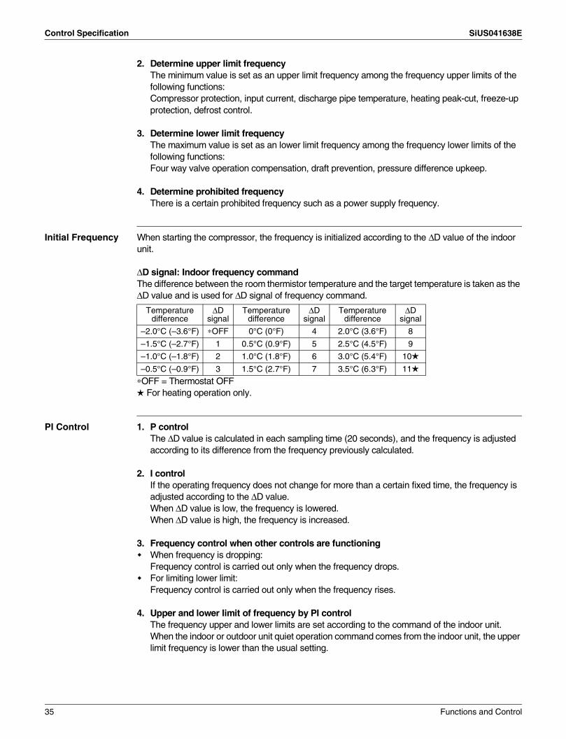
Initial Frequency When starting the compressor, the frequency is initialized according to the ∆D value of the indoor unit.
∆D signal: Indoor frequency commandThe difference between the room thermistor temperature and the target temperature is taken as the ∆D value and is used for ∆D signal of frequency command.
∗OFF = Thermostat OFF For heating operation only.
PI Control 1. P controlThe ∆D value is calculated in each sampling time (20 seconds), and the frequency is adjusted according to its difference from the frequency previously calculated.
2. I controlIf the operating frequency does not change for more than a certain fixed time, the frequency is adjusted according to the ∆D value.When ∆D value is low, the frequency is lowered.When ∆D value is high, the frequency is increased.
3. Frequency control when other controls are functioningWhen frequency is dropping: Frequency control is carried out only when the frequency drops.For limiting lower limit: Frequency control is carried out only when the frequency rises.
4. Upper and lower limit of frequency by PI control The frequency upper and lower limits are set according to the command of the indoor unit.When the indoor or outdoor unit quiet operation command comes from the indoor unit, the upper limit frequency is lower than the usual setting.
Temperature difference
∆D signal
Temperature difference
∆D signal
Temperature difference
∆D signal
–2.0°C (–3.6°F) ∗OFF 0°C (0°F) 4 2.0°C (3.6°F) 8
–1.5°C (–2.7°F) 1 0.5°C (0.9°F) 5 2.5°C (4.5°F) 9
–1.0°C (–1.8°F) 2 1.0°C (1.8°F) 6 3.0°C (5.4°F) 10
–0.5°C (–0.9°F) 3 1.5°C (2.7°F) 7 3.5°C (6.3°F) 11
35 Functions and Control

SiUS041638E Control Specification
3.3 Controls at Mode Changing/Start-up3.3.1 Preheating Operation
Outline The inverter operation in open phase starts with the conditions of the outdoor temperature and the preheating command from the indoor unit.
Details ON ConditionWhen the outdoor temperature is below 6°C (42.8°F), the inverter operation in open phase starts.
OFF ConditionWhen the outdoor temperature is higher than 8°C (46.4°F), the inverter operation in open phase stops.
3.3.2 Four Way Valve Switching
Outline The four way valve coil is energized/not energized depending on the operation mode. (Heating: ON, Cooling/Dry/Defrost: OFF) In order to eliminate the switching sound as the four way valve coil switches from ON to OFF when the heating is stopped, the OFF delay switch of the four way valve is carried out.
Details OFF delay switch of four way valveThe four way valve coil is energized for 160 seconds after the operation is stopped.
3.3.3 Four Way Valve Operation Compensation
Outline At the beginning of operation as the four way valve is switched, the pressure difference to activate the four way valve is acquired when the output frequency is higher than a certain fixed frequency, for a certain fixed time.
Details Starting Conditions1. Compressor starts and the four way valve switches from OFF to ON2. Four way valve switches from ON to OFF during operation3. Compressor starts after resetting4. Compressor starts after the fault of four way valve switchingThe lower limit of frequency keeps A Hz for B seconds with any conditions 1 through 4 above.When the outdoor temperature is above C in heating, the frequency decreases depending on the outdoor temperature.
RK30/36NMVJU RX30/36NMVJU
Cooling Heating Cooling Heating
A (Hz) 46 — 46 52
B (seconds) 60 60
C(°C) 15 15
(°F) 59 59
Functions and Control 36

Control Specification SiUS041638E
3.3.4 3-Minute StandbyTurning on the compressor is prohibited for 3 minutes after turning it off.(The function is not activated when defrosting.)
3.3.5 Compressor Protection FunctionWhen turning the compressor from OFF to ON, the upper limit of frequency is set as follows. (The function is not activated when defrosting.)
RK30/36NMVJU RX30/36NMVJU
Cooling Heating Cooling Heating
A (Hz) 28 — 28 30
B (Hz) 42 — 42 78
C (Hz) 56 — 56 118
D (seconds) 180 — 180 1080
E (seconds) 180 — 180 90
F (seconds) 180 — 180 240
(sec.) Time(R13528)
(Hz) Frequency
CB
D E F
A
37 Functions and Control

SiUS041638E Control Specification
3.4 Discharge Pipe Temperature Control
Outline The discharge pipe temperature is used as the internal temperature of the compressor. If the discharge pipe temperature rises above a certain level, the upper limit of frequency is set to keep the discharge pipe temperature from rising further.
Details
RK(X)30/36NMVJU
(°C) (°F)
A 120 248.0
B 111 231.8
C 109 228.2
D 107 224.6
E 107 224.6
Zone Control
Stop zone When the temperature reaches the stop zone, the compressor stops.
Dropping zone The upper limit of frequency decreases.
Keep zone The upper limit of frequency is kept.
Up zone The upper limit of frequency increases.
Reset zone The upper limit of frequency is canceled.
(R14722)Discharge pipe
temperature
Stop zone
Dropping zone
Keep zone
Up zoneReset zone
E
A
B
C
D
Functions and Control 38
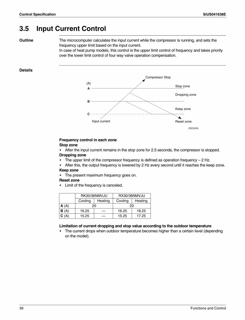
Control Specification SiUS041638E
3.5 Input Current Control
Outline The microcomputer calculates the input current while the compressor is running, and sets the frequency upper limit based on the input current.In case of heat pump models, this control is the upper limit control of frequency and takes priority over the lower limit control of four way valve operation compensation.
Details
Frequency control in each zoneStop zone
After the input current remains in the stop zone for 2.5 seconds, the compressor is stopped.Dropping zone
The upper limit of the compressor frequency is defined as operation frequency – 2 Hz.After this, the output frequency is lowered by 2 Hz every second until it reaches the keep zone.
Keep zoneThe present maximum frequency goes on.
Reset zoneLimit of the frequency is canceled.
Limitation of current dropping and stop value according to the outdoor temperatureThe current drops when outdoor temperature becomes higher than a certain level (depending on the model).
RK30/36NMVJU RX30/36NMVJUCooling Heating Cooling Heating
A (A) 20 20B (A) 16.25 — 16.25 18.25C (A) 15.25 — 15.25 17.25
Compressor Stop
Input current
Dropping zone
Stop zone
Keep zone
Reset zone
(R23249)
A
(A)
B
C
39 Functions and Control
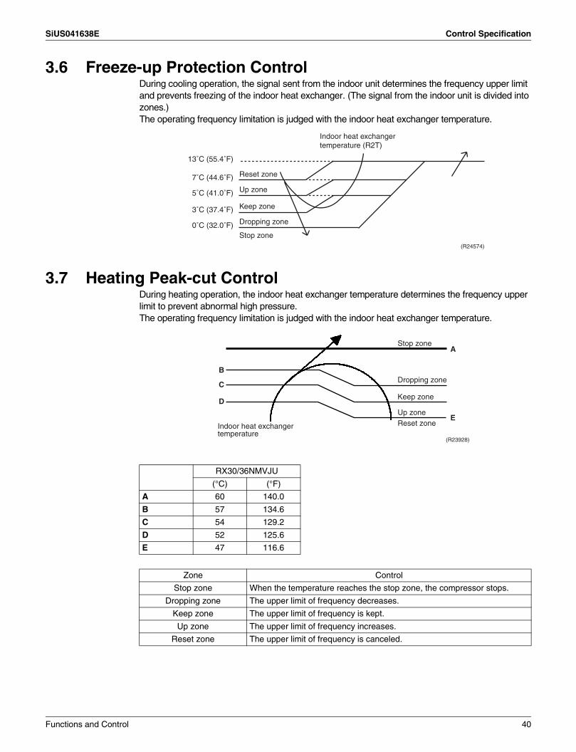
SiUS041638E Control Specification
3.6 Freeze-up Protection ControlDuring cooling operation, the signal sent from the indoor unit determines the frequency upper limit and prevents freezing of the indoor heat exchanger. (The signal from the indoor unit is divided into zones.)The operating frequency limitation is judged with the indoor heat exchanger temperature.
3.7 Heating Peak-cut ControlDuring heating operation, the indoor heat exchanger temperature determines the frequency upper limit to prevent abnormal high pressure.The operating frequency limitation is judged with the indoor heat exchanger temperature.
(R24574)
Reset zone
Indoor heat exchanger temperature (R2T)
Up zone
Keep zone
Dropping zone
Stop zone
13˚C (55.4˚F)
7˚C (44.6˚F)
5˚C (41.0˚F)
3˚C (37.4˚F)
0˚C (32.0˚F)
RX30/36NMVJU
(°C) (°F)
A 60 140.0
B 57 134.6
C 54 129.2
D 52 125.6
E 47 116.6
Zone Control
Stop zone When the temperature reaches the stop zone, the compressor stops.
Dropping zone The upper limit of frequency decreases.
Keep zone The upper limit of frequency is kept.
Up zone The upper limit of frequency increases.
Reset zone The upper limit of frequency is canceled.
Indoor heat exchanger temperature
Stop zone
Dropping zone
Keep zone
Up zoneReset zone
(R23928)
D
C
B
A
E
Functions and Control 40

Control Specification SiUS041638E
3.8 Outdoor Fan Control1. Fan ON control to cool down the electrical boxThe outdoor fan is turned ON when the electrical box temperature is high while the compressor is OFF.
2. Fan OFF control during defrostingThe outdoor fan is turned OFF during defrosting.
3. Fan OFF delay when stoppedThe outdoor fan is turned OFF 60 seconds after the compressor stops.
4. Fan speed control for pressure difference upkeepThe rotation speed of the outdoor fan is controlled for keeping the pressure difference during cooling operation with low outdoor temperature.
When the pressure difference is low, the rotation speed of the outdoor fan is reduced.When the pressure difference is high, the rotation speed of the outdoor fan is controlled as well as normal operation.
5. Fan speed control during forced cooling operationThe outdoor fan is controlled as well as normal operation during forced cooling operation.
6. Fan speed control during POWERFUL operationThe rotation speed of the outdoor fan is increased during POWERFUL operation.
7. Fan speed control during indoor/outdoor unit quiet operationThe rotation speed of the outdoor fan is reduced by the command of the indoor/outdoor unit quiet operation.
8. Fan ON/OFF control when operation (cooling, heating, dry) starts/stopsThe outdoor fan is turned ON when the operation starts. The outdoor fan is turned OFF when the operation stops.
3.9 Liquid Compression Protection Function
Outline In order to increase the dependability of the compressor, the compressor is stopped according to the outdoor temperature.
Details Operation stops depending on the outdoor temperatureCompressor turns off under the conditions that the system is in cooling operation and outdoor temperature is below 0°C (32°F).
41 Functions and Control

SiUS041638E Control Specification
3.10 Defrost Control
Outline Defrosting is carried out by the cooling cycle (reverse cycle). The defrosting time or outdoor heat exchanger temperature must be more than a certain value to finish defrosting.
Details Conditions for Starting DefrostThe starting conditions are determined with the outdoor temperature and the outdoor heat exchanger temperature.The system is in heating operation.The compressor operates for 6 minutes.More than A minutes (depending on the duration of the previous defrost control) of accumulated time have passed since the start of the operation, or ending the previous defrosting.
Conditions for Canceling DefrostThe judgment is made with the outdoor heat exchanger temperature (B).
RX30/36NMVJU
A (minute) 15 ~ 25
B(°C) 6 ~ 30
(°F) 42.8 ~ 86.0
C (Hz) 58
D (Hz) 58
E (seconds) 60
F (seconds) 60
G (seconds) 340
H (seconds) 60
J (seconds) 8
K (pulse) 200
L (pulse) 150
M (pulse) 200
Frequency
Compressor
Four way valve
Fan
ON
OFF
ON
OFF
ON
OFF
0 Hz 0 Hz
C HzD Hz
J sec.
PI control
8 sec.
H sec.
(R21661)
E sec.
F sec.
G sec.
L pulse zone
Electronic expansion valve opening Normal
controlK pulse
zoneM pulse
zoneStarting control
Functions and Control 42

Control Specification SiUS041638E
3.11 Electronic Expansion Valve Control
Outline The following items are included in the electronic expansion valve control.Electronic expansion valve is fully closed1. Electronic expansion valve is fully closed when turning on the power.2. Pressure equalizing controlOpen Control1. Electronic expansion valve control when starting operation2. Electronic expansion valve control when the frequency changes3. Electronic expansion valve control for defrosting4. Electronic expansion valve control when the discharge pipe temperature is abnormally high5. Electronic expansion valve control when the discharge pipe thermistor is disconnectedFeedback ControlTarget discharge pipe temperature control
Details The following are examples of electronic expansion valve control for each operation mode.
: Available: Not available
Control
Status
Starting operation control
Control when the frequency changes
Target discharge pipe temperature control
Discharge pipe thermistor disconnection control
High discharge pipe temperature control
Defrost control (heating only)
Pressure equalizing control
Opening limit control
Pow
er o
n ; C
ompr
esso
r st
op
Ope
ratio
n st
art
Fre
quen
cy c
hang
e un
der
star
ting
cont
rol
Dur
ing
targ
et d
isch
arge
pip
e te
mpe
ratu
re c
ontr
ol
Fre
quen
cy c
hang
e un
der
targ
et d
isch
arge
pip
e te
mpe
ratu
re c
ontr
ol
Dis
char
ge p
ipe
ther
mis
tor
disc
onne
ctio
n
Fre
quen
cy c
hang
e un
der
disc
harg
e pi
pe th
erm
isto
r di
scon
nect
ion
cont
rol
Dur
ing
defr
ost c
ontr
ol
43 Functions and Control

SiUS041638E Control Specification
3.11.1 Initialization as Power Supply OnThe electronic expansion valve is initialized (fully closed) when the power is turned on. Then, the valve opening is set and the pressure is equalized.
3.11.2 Pressure Equalizing ControlWhen the compressor is stopped, the pressure equalizing control is activated. The electronic expansion valve opens and the pressure is equalized.
3.11.3 Opening Limit ControlThe maximum and minimum opening of the electronic expansion valve are limited.
The electronic expansion valve is fully closed when cooling operation stops, and is opened at a fixed degree during defrosting.
3.11.4 Starting Operation ControlThe electronic expansion valve opening is controlled when the operation starts, thus preventing superheating or liquid compression.
3.11.5 Control when the frequency changesWhen the target discharge pipe temperature control is active, if the target frequency changes to a specified value in a certain period of time, the target discharge pipe temperature control is canceled and the target opening of the electronic expansion valve is changed according to the frequency shift.
3.11.6 High Discharge Pipe Temperature ControlWhen the compressor is operating, if the discharge pipe temperature exceeds a certain value, the electronic expansion valve opens and the refrigerant runs to the low pressure side. This procedure lowers the discharge pipe temperature.
3.11.7 Discharge Pipe Thermistor Disconnection Control
Outline The disconnection of the discharge pipe thermistor is detected by comparing the discharge pipe temperature with the condensation temperature. If the discharge pipe thermistor is disconnected, the electronic expansion valve opens according to the outdoor temperature and the operation frequency, operates for a specified time, and then stops.After 3 minutes, the operation restarts and checks if the discharge pipe thermistor is disconnected. If the discharge pipe thermistor is disconnected, the system stops after operating for a specified time.If the disconnection is detected repeatedly, the system is shut down. When the compressor runs for 60 minutes without any error, the error counter is reset.
RK(X)30/36NMVJU
Maximum opening (pulse) 480
Minimum opening (pulse) 56
Functions and Control 44
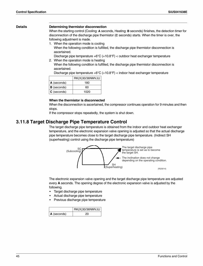
Control Specification SiUS041638E
Details Determining thermistor disconnectionWhen the starting control (Cooling: A seconds, Heating: B seconds) finishes, the detection timer for disconnection of the discharge pipe thermistor (C seconds) starts. When the timer is over, the following adjustment is made.1. When the operation mode is cooling
When the following condition is fulfilled, the discharge pipe thermistor disconnection is ascertained.Discharge pipe temperature +6°C (+10.8°F) < outdoor heat exchanger temperature
2. When the operation mode is heatingWhen the following condition is fulfilled, the discharge pipe thermistor disconnection is ascertained.Discharge pipe temperature +6°C (+10.8°F) < indoor heat exchanger temperature
When the thermistor is disconnectedWhen the disconnection is ascertained, the compressor continues operation for 9 minutes and then stops.If the compressor stops repeatedly, the system is shut down.
3.11.8 Target Discharge Pipe Temperature ControlThe target discharge pipe temperature is obtained from the indoor and outdoor heat exchanger temperature, and the electronic expansion valve opening is adjusted so that the actual discharge pipe temperature becomes close to the target discharge pipe temperature. (Indirect SH (superheating) control using the discharge pipe temperature)
The electronic expansion valve opening and the target discharge pipe temperature are adjusted every A seconds. The opening degree of the electronic expansion valve is adjusted by the following.
Target discharge pipe temperatureActual discharge pipe temperaturePrevious discharge pipe temperature
RK(X)30/36NMVJU
A (seconds) 180
B (seconds) 60
C (seconds) 1020
RK(X)30/36NMVJU
A (seconds) 20
SC (Subcooling)
SH (Superheating)
The target discharge pipe temperature is set as to become the target SH.
The inclination does not change depending on the operating condition.
(R23014)
45 Functions and Control
SiUS041638E Control Specification
3.12 Malfunctions3.12.1 Sensor Malfunction Detection
Sensor malfunction can be detected in the following thermistors:1. Outdoor heat exchanger thermistor2. Discharge pipe thermistor3. Radiation fin thermistor4. Outdoor temperature thermistor
3.12.2 Detection of Overcurrent and Overload
Outline An excessive output current is detected and the OL temperature is observed to protect the compressor.
Details If the OL (compressor head) temperature exceeds 130°C (266°F), the system shuts down the compressor.If the inverter current exceeds 20 A, the system shuts down the compressor.The upper limit of the current decreases when the outdoor temperature exceeds a certain level.
Functions and Control 46
SiUS041638E
47 Remote Controller
Part 5Remote Controller
1. Remote Controller .....................................................................................48
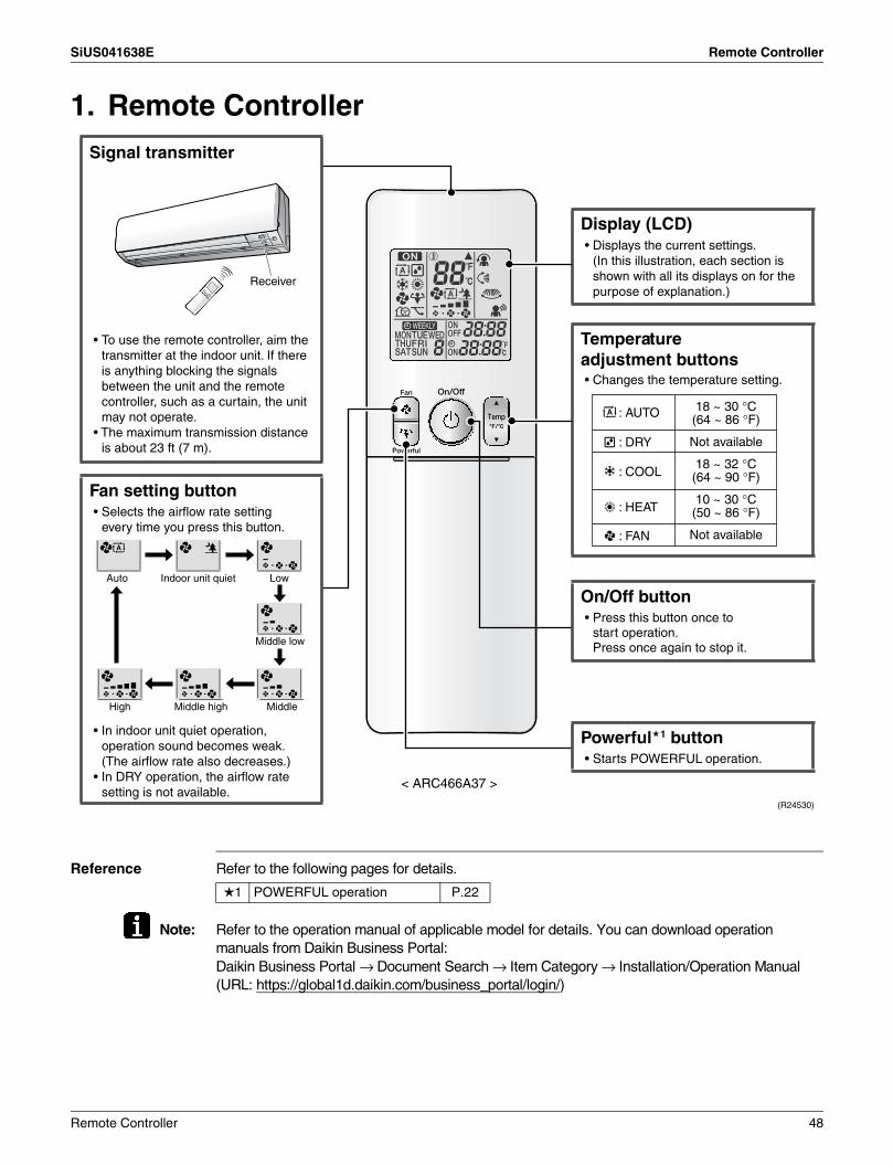
SiUS041638E Remote Controller
1. Remote Controller
Reference Refer to the following pages for details.
Note: Refer to the operation manual of applicable model for details. You can download operation manuals from Daikin Business Portal:Daikin Business Portal → Document Search → Item Category → Installation/Operation Manual(URL: https://global1d.daikin.com/business_portal/login/)
< ARC466A37 >
Signal transmitter
Powerful 1 button• Starts POWERFUL operation.
Display (LCD)
• Changes the temperature setting.
On/Off buttonAuto Indoor unit quiet Low
Middle low
MiddleMiddle highHigh
• Press this button once to start operation.Press once again to stop it.
Temperature adjustment buttons
• Displays the current settings.(In this illustration, each section is shown with all its displays on for the purpose of explanation.)
• To use the remote controller, aim the transmitter at the indoor unit. If there is anything blocking the signals between the unit and the remote controller, such as a curtain, the unit may not operate.
• The maximum transmission distance is about 23 ft (7 m).
Fan setting button
• In indoor unit quiet operation, operation sound becomes weak. (The airflow rate also decreases.)
• In DRY operation, the airflow rate setting is not available.
• Selects the airflow rate setting every time you press this button.
(R24530)
: AUTO
: DRY
: COOL
: HEAT
: FAN
18 ~ 30 °C(64 ~ 86 °F)
Not available
18 ~ 32 °C(64 ~ 90 °F)
10 ~ 30 °C(50 ~ 86 °F)
Not available
Receiver
1 POWERFUL operation P.22
Remote Controller 48
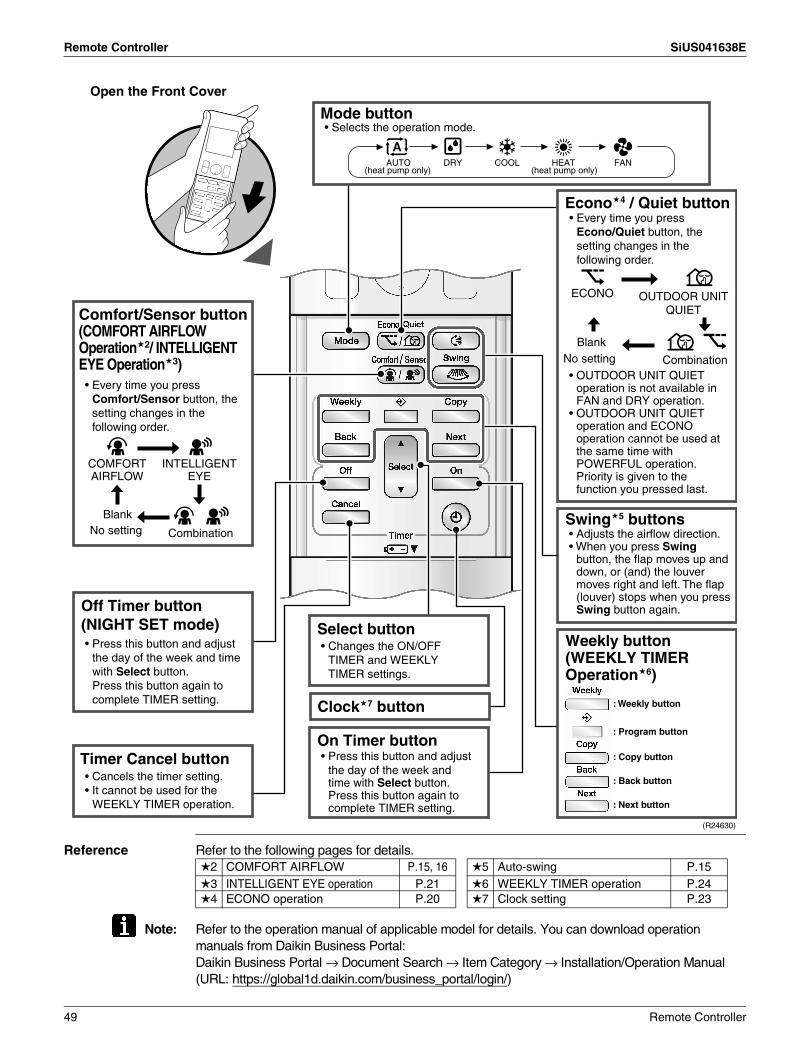
Remote Controller SiUS041638E
Open the Front Cover
Reference Refer to the following pages for details.
Note: Refer to the operation manual of applicable model for details. You can download operation manuals from Daikin Business Portal:Daikin Business Portal → Document Search → Item Category → Installation/Operation Manual(URL: https://global1d.daikin.com/business_portal/login/)
Swing 5 buttons
On Timer button
Clock 7 button
Select button• Press this button and adjust
the day of the week and time with Select button.Press this button again to complete TIMER setting.
Timer Cancel button• Cancels the timer setting.• It cannot be used for the
WEEKLY TIMER operation.
• Changes the ON/OFF TIMER and WEEKLY TIMER settings.
• Adjusts the airflow direction.• When you press Swing
button, the flap moves up and down, or (and) the louver moves right and left. The flap (louver) stops when you press Swing button again.
• Press this button and adjust the day of the week and time with Select button.Press this button again to complete TIMER setting.
(R24630)
: Weekly button
: Program button
: Copy button
: Back button
: Next button
• OUTDOOR UNIT QUIET operation is not available in FAN and DRY operation.
• OUTDOOR UNIT QUIET operation and ECONO operation cannot be used at the same time with POWERFUL operation. Priority is given to the function you pressed last.
Econo 4 / Quiet button
BlankNo setting Combination
Comfort/Sensor button(COMFORT AIRFLOW Operation 2/ INTELLIGENT EYE Operation 3)
INTELLIGENT EYE
COMFORT AIRFLOW
• Every time you press Comfort/Sensor button, the setting changes in the following order.
ECONO
BlankNo setting Combination
• Every time you press Econo/Quiet button, the setting changes in the following order.
OUTDOOR UNIT QUIET
Mode button • Selects the operation mode.
Off Timer button(NIGHT SET mode)
Weekly button (WEEKLY TIMER Operation 6)
(heat pump only)AUTO DRY COOL HEAT FAN
(heat pump only)
2 COMFORT AIRFLOW P.15, 16 5 Auto-swing P.153 INTELLIGENT EYE operation P.21 6 WEEKLY TIMER operation P.244 ECONO operation P.20 7 Clock setting P.23
49 Remote Controller
SiUS041638E
Part 6Service Diagnosis
1. General Problem Symptoms and Check Items .........................................522. Troubleshooting with LED .........................................................................53
2.1 Indoor Unit.................................................................................................. 532.2 Outdoor Unit ............................................................................................... 53
3. Service Diagnosis .....................................................................................544. Troubleshooting ........................................................................................57
4.1 Error Codes and Description ...................................................................... 574.2 Indoor Unit PCB Abnormality ..................................................................... 584.3 Freeze-up Protection Control/Heating Peak-cut Control ............................ 604.4 Indoor Fan Motor (DC Motor) or Related Abnormality ............................... 614.5 Thermistor or Related Abnormality (Indoor Unit)........................................ 634.6 Low-voltage Detection or Over-voltage Detection...................................... 644.7 Signal Transmission Error (between Indoor Unit and Outdoor Unit) .......... 664.8 Signal Transmission Error on Outdoor Unit PCB ....................................... 684.9 Mismatching of Indoor Unit and Outdoor Unit ............................................ 694.10 Outdoor Unit PCB Abnormality................................................................... 704.11 OL Activation (Compressor Overload) ....................................................... 714.12 Compressor Lock ....................................................................................... 734.13 DC Fan Lock (Outdoor Fan)....................................................................... 744.14 Input Overcurrent Detection ....................................................................... 754.15 Four Way Valve Abnormality...................................................................... 764.16 Discharge Pipe Temperature Control......................................................... 784.17 High Pressure Control in Cooling ............................................................... 794.18 System Shutdown due to Compressor Internal Temperature
Abnormality ................................................................................................ 804.19 Compressor System Sensor Abnormality .................................................. 814.20 Position Sensor Abnormality ...................................................................... 824.21 CT or Related Abnormality ......................................................................... 844.22 Thermistor or Related Abnormality (Outdoor Unit)..................................... 864.23 Electrical Box Temperature Rise................................................................ 884.24 Radiation Fin Temperature Rise ................................................................ 894.25 Output Overcurrent Detection .................................................................... 90
5. Check ........................................................................................................925.1 Thermistor Resistance Check .................................................................... 925.2 Indoor Fan Motor Connector Output Check ............................................... 935.3 Power Supply Waveforms Check............................................................... 935.4 Electronic Expansion Valve Check............................................................. 945.5 Four Way Valve Performance Check ......................................................... 955.6 Inverter Unit Refrigerant System Check..................................................... 955.7 Inverter Analyzer Check ............................................................................. 965.8 Rotation Pulse Check on the Outdoor Unit PCB ........................................ 98
Service Diagnosis 50
SiUS041638E
5.9 Installation Condition Check....................................................................... 995.10 Discharge Pressure Check......................................................................... 995.11 Outdoor Fan System Check ..................................................................... 1005.12 Main Circuit Short Check.......................................................................... 1005.13 Capacitor Voltage Check.......................................................................... 1015.14 Power Module Check ............................................................................... 101
51 Service Diagnosis

SiUS041638E General Problem Symptoms and Check Items
1. General Problem Symptoms and Check ItemsSymptom Check Item Details Reference
Page
The unit does not operate. Check the power supply. Check if the rated voltage is supplied. —
Check the type of the indoor unit. Check if the indoor unit type is compatible with the outdoor unit. —
Check the outdoor temperature. Heating/cooling operations are not available when the outdoor temperature is out of the operation limit. Check the reference page for the operation limit.
117
Diagnose with remote controller indication. — 57
Check the remote controller addresses.
Check if address settings for the remote controller and indoor unit are correct. 108
Operation sometimes stops.
Check the power supply. A power failure of 2 to 10 cycles stops air conditioner operation. (Operation lamp OFF) —
Check the outdoor temperature. Heating/cooling operations are not available when the outdoor temperature is out of the operation limit. Check the reference page for the operation limit.
117
Diagnose with remote controller indication. — 57
The unit operates but does not cool, or does not heat.
Check for wiring and piping errors in the connection between the indoor unit and outdoor unit.
— —
Check for thermistor detection errors. Check if the thermistor is mounted securely. —
Check for faulty operation of the electronic expansion valve.
Set the unit to cooling operation, and check the temperature of the liquid pipe to see if the electronic expansion valve works.
—
Diagnose with remote controller indication. — 57
Diagnose by service port pressure and operating current.
Check for refrigerant shortage. —
Large operating noise and vibrations
Check the output voltage of the power module. — 101
Check the power module. — —
Check the installation condition. Check if the required spaces for installation (specified in the installation manual) are provided. —
Service Diagnosis 52

Troubleshooting with LED SiUS041638E
2. Troubleshooting with LED2.1 Indoor Unit
Operation Lamp The operation lamp blinks when any of the following errors is detected.1. A protection device of the indoor or outdoor unit is activated, or the thermistor malfunctions.2. A signal transmission error occurs between the indoor and outdoor units.In either case, conduct the diagnostic procedure described in the following pages.
2.2 Outdoor UnitThe outdoor unit has one green LED (LED A) on the PCB. When the microcomputer works in order, the LED A blinks. However, the LED A turns OFF while the standby electricity saving function is activated and the power supply is OFF. (Refer to page 9 for the location of LED A.)
(R24553)
Operation lamp (green)
53 Service Diagnosis
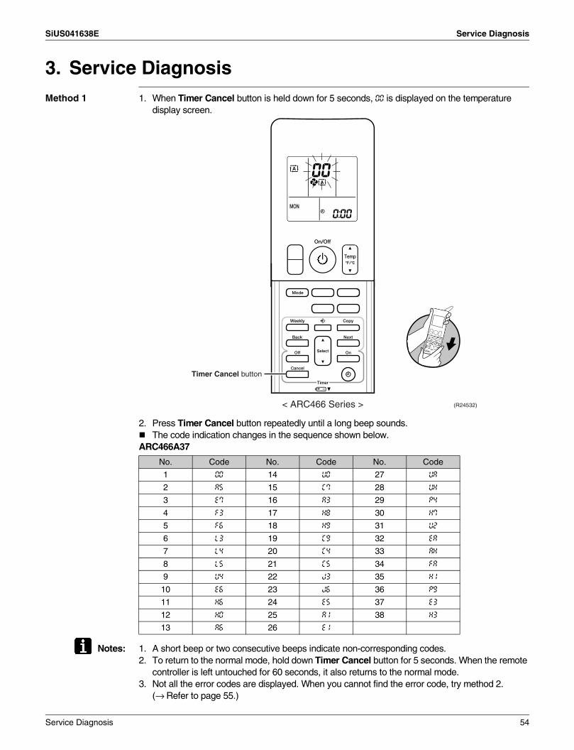
SiUS041638E Service Diagnosis
3. Service DiagnosisMethod 1 1. When Timer Cancel button is held down for 5 seconds, 00 is displayed on the temperature
display screen.
2. Press Timer Cancel button repeatedly until a long beep sounds.The code indication changes in the sequence shown below.
ARC466A37
Notes: 1. A short beep or two consecutive beeps indicate non-corresponding codes.2. To return to the normal mode, hold down Timer Cancel button for 5 seconds. When the remote
controller is left untouched for 60 seconds, it also returns to the normal mode.3. Not all the error codes are displayed. When you cannot find the error code, try method 2.
(→ Refer to page 55.)
No. Code No. Code No. Code
1 00 14 U0 27 UA
2 A5 15 C7 28 UH
3 E7 16 A3 29 P4
4 F3 17 H8 30 H7
5 F6 18 H9 31 U2
6 L3 19 C9 32 EA
7 L4 20 C4 33 AH
8 L5 21 C5 34 FA
9 U4 22 J3 35 H1
10 E6 23 J6 36 P9
11 H6 24 E5 37 E3
12 H0 25 A1 38 H3
13 A6 26 E1
(R24532)< ARC466 Series >
Timer Cancel button
Service Diagnosis 54
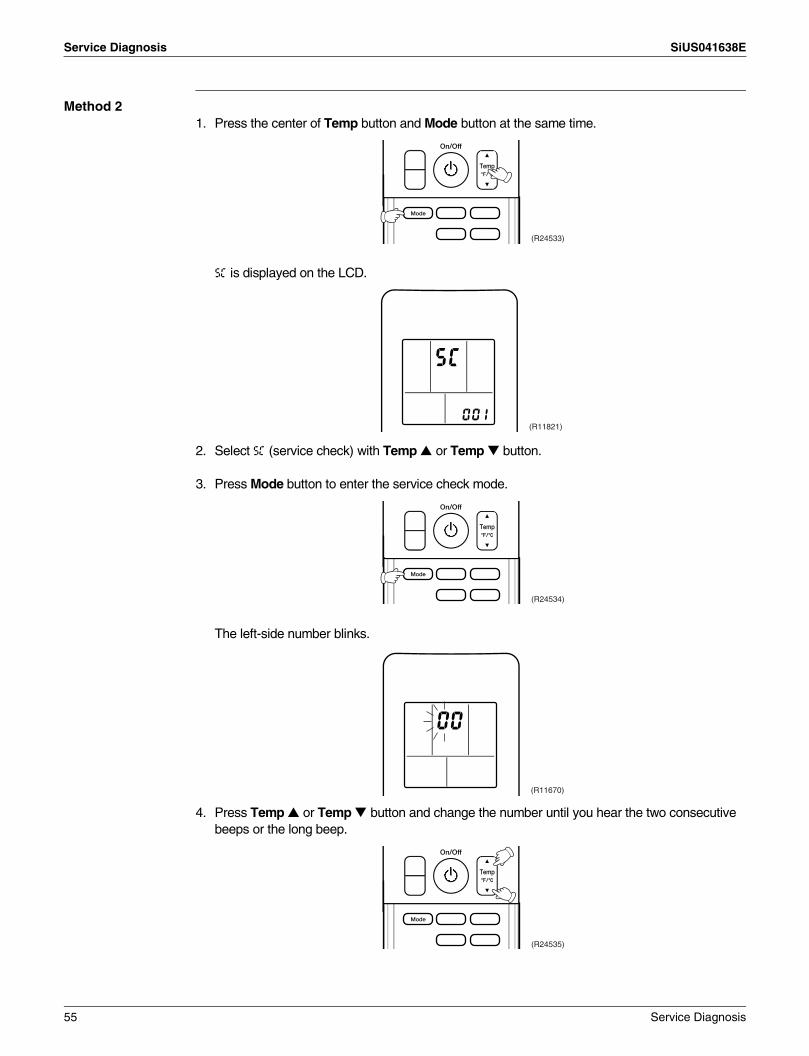
Service Diagnosis SiUS041638E
Method 21. Press the center of Temp button and Mode button at the same time.
5C is displayed on the LCD.
2. Select 5C (service check) with Temp or Temp button.
3. Press Mode button to enter the service check mode.
The left-side number blinks.
4. Press Temp or Temp button and change the number until you hear the two consecutive beeps or the long beep.
(R24533)
(R11821)
(R24534)
(R11670)
(R24535)
55 Service Diagnosis
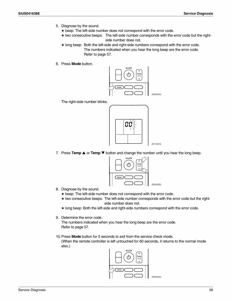
SiUS041638E Service Diagnosis
5. Diagnose by the sound. beep: The left-side number does not correspond with the error code. two consecutive beeps: The left-side number corresponds with the error code but the right-
side number does not. long beep: Both the left-side and right-side numbers correspond with the error code.
The numbers indicated when you hear the long beep are the error code.Refer to page 57.
6. Press Mode button.
The right-side number blinks.
7. Press Temp or Temp button and change the number until you hear the long beep.
8. Diagnose by the sound. beep: The left-side number does not correspond with the error code. two consecutive beeps: The left-side number corresponds with the error code but the right-
side number does not. long beep: Both the left-side and right-side numbers correspond with the error code.
9. Determine the error code.The numbers indicated when you hear the long beep are the error code.Refer to page 57.
10.Press Mode button for 5 seconds to exit from the service check mode.(When the remote controller is left untouched for 60 seconds, it returns to the normal mode also.)
(R24534)
(R11673)
(R24535)
(R24534)
Service Diagnosis 56

Troubleshooting SiUS041638E
4. Troubleshooting4.1 Error Codes and Description
: Displayed only when system-down occurs.
Error Codes Description ReferencePage
System 00 Normal —
U2 Low-voltage detection or over-voltage detection 64
U4 Signal transmission error (between indoor unit and outdoor unit) 66
UA Mismatching of indoor unit and outdoor unit 69
IndoorUnit
A1 Indoor unit PCB abnormality 58
A5 Freeze-up protection control/heating peak-cut control 60
A6 Indoor fan motor (DC motor) or related abnormality 61
C4 Indoor heat exchanger thermistor or related abnormality 63
C9 Room temperature thermistor or related abnormality 63
OutdoorUnit
E1 Outdoor unit PCB abnormality 70
E5 OL activation (compressor overload) 71
E6 Compressor lock 73
E7 DC fan lock (outdoor fan) 74
E8 Input overcurrent detection 75
EA Four way valve abnormality 76
F3 Discharge pipe temperature control 78
F6 High pressure control in cooling 79
F8 System shutdown due to compressor internal temperature abnormality 80
H0 Compressor system sensor abnormality 81
H6 Position sensor abnormality 82
H8 CT or related abnormality 84
H9 Outdoor temperature thermistor or related abnormality 86
J3 Discharge pipe thermistor or related abnormality 86
J6 Outdoor heat exchanger thermistor or related abnormality 86
L3 Electrical box temperature rise 88
L4 Radiation fin temperature rise 89
L5 Output overcurrent detection 90
P4 Radiation fin thermistor or related abnormality 86
U7 Signal transmission error on outdoor unit PCB 68
57 Service Diagnosis

SiUS041638E Troubleshooting
4.2 Indoor Unit PCB Abnormality
Error Code A1
Method of Error Detection
The system checks if the circuit works properly within the microcomputer of the indoor unit.
Error Decision Conditions
The system cannot set the internal settings.
Supposed Causes
Wrong models interconnectedDefective indoor unit PCBDisconnection of connectorReduction of power supply voltage
Service Diagnosis 58
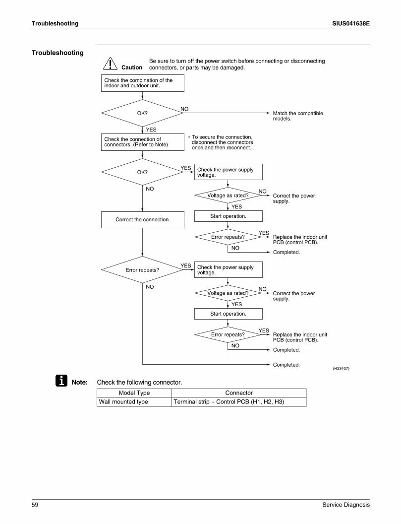
Troubleshooting SiUS041638E
Troubleshooting
Note: Check the following connector.
Check the combination of the indoor and outdoor unit.
OK?
Check the connection of connectors. (Refer to Note)
Correct the connection.
OK? Check the power supply voltage.
Start operation.
Voltage as rated?
Error repeats?
Check the power supply voltage.
Start operation.
Voltage as rated?
Error repeats?
Error repeats?
YES
NO
NO
YES
NO
NO
YES
(R23407)
Caution
∗ To secure the connection, disconnect the connectors once and then reconnect.
YES
NO
YES
NO
YES
NO
YES
Match the compatible models.
Correct the power supply.
Replace the indoor unit PCB (control PCB).
Completed.
Completed.
Correct the power supply.
Replace the indoor unit PCB (control PCB).
Completed.
Be sure to turn off the power switch before connecting or disconnecting connectors, or parts may be damaged.
Model Type Connector
Wall mounted type Terminal strip ~ Control PCB (H1, H2, H3)
59 Service Diagnosis

SiUS041638E Troubleshooting
4.3 Freeze-up Protection Control/Heating Peak-cut Control
Error Code A5
Method of Error Detection
Freeze-up protection controlDuring cooling operation, the freeze-up protection control (operation halt) is activated according to the temperature detected by the indoor heat exchanger thermistor.Heating peak-cut controlDuring heating operation, the temperature detected by the indoor heat exchanger thermistor is used for the heating peak-cut control (operation halt, outdoor fan stop, etc.)
Error Decision Conditions
Freeze-up protection controlDuring cooling operation, the indoor heat exchanger temperature is below 0°C (32°F).Heating peak-cut controlDuring heating operation, the indoor heat exchanger temperature is above about 60°C (140°F) (depending on the model).
Supposed Causes
Short-circuited airClogged air filter of the indoor unitDust accumulation on the indoor heat exchangerDefective indoor heat exchanger thermistorDefective indoor unit PCB
Troubleshooting
Check No.01Refer to P.92
NO
NO
NO
Check No. 01Check the indoor heat exchanger thermistor.
YES
YES
(R21064)
YES
YES
NO
Caution
Provide sufficient air passage.
Clean the air filter.
Clean the indoor heat exchanger.
Replace the indoor unit PCB (control PCB).
Replace the indoor heat exchanger thermistor.
As described in the
thermistor characteristic chart?
Check the air filter.
Check the dust accumulation on the indoor heat exchanger.
Is there any short circuit?
Dirty?
Dirty?
Check the air passage.
Be sure to turn off the power switch before connecting or disconnecting connectors, or parts may be damaged.
Service Diagnosis 60

Troubleshooting SiUS041638E
4.4 Indoor Fan Motor (DC Motor) or Related Abnormality
Error Code A6
Method of Error Detection
The rotation speed detected by the Hall IC during fan motor operation is used to determine abnormal fan motor operation.
Error Decision Conditions
The detected rotation speed does not reach the demanded rotation speed of the target tap, and is less than 50% of the maximum fan motor rotation speed.
Supposed Causes
Remarkable decrease in power supply voltageLayer short inside the fan motor windingBreaking of wire inside the fan motorBreaking of the fan motor lead wiresDefective capacitor of the fan motorDefective indoor unit PCB
61 Service Diagnosis

SiUS041638E Troubleshooting
Troubleshooting
Check No.02Refer to P.93
Note: The rotation pulse is the feedback signal from the indoor fan motor.
CautionBe sure to turn off the power switch before connecting or disconnecting connectors, or parts may be damaged.
Correct the power supply.
NO
Check the power supply voltage.
Turn off the power and disconnect the fan motor connector, then turn the power on.
Check No.02Check the output of the fan motor connector.
YES
YES
NO
YES
YES
NO
NO
NO
Note: The motor may break when the motor connector is disconnected while the power is turned on.(Be sure to turn off the power before reconnecting the connector.)
Replace the indoor fan motor.
Replace the indoor unit PCB (control PCB).
Replace the indoor unit PCB (control PCB).
Does the fan rotate smoothly?
Does the fan rotate?
Motor power supply
voltage 310 ~ 340 VDC?
Turn off the power and rotate the fan by hand.
Turn on the power and start operation.
Check No.02Check the output of the fan motor connector.
(R22444)
YES
NO
YES
NO
YES
NOReplace the indoor fan motor.
Replace the indoor unit PCB (control PCB).
Replace the indoor unit PCB (control PCB).
Replace the indoor unit PCB (control PCB).
Replace the indoor fan motor.
Stop the fan motor.
YES
Is the voltage
fluctuation within ±10% from
the rated value?
Motor control voltage 15 VDC generated?
Rotation command voltage
1 ~ 6.5 VDC?
Indoor fan motor rotation pulse
generated?
Indoor fan motor rotation pulse
generated?
Service Diagnosis 62
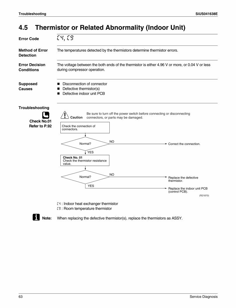
Troubleshooting SiUS041638E
4.5 Thermistor or Related Abnormality (Indoor Unit)
Error Code C4, C9
Method of Error Detection
The temperatures detected by the thermistors determine thermistor errors.
Error Decision Conditions
The voltage between the both ends of the thermistor is either 4.96 V or more, or 0.04 V or less during compressor operation.
Supposed Causes
Disconnection of connectorDefective thermistor(s)Defective indoor unit PCB
Troubleshooting
Check No.01Refer to P.92
C4 : Indoor heat exchanger thermistorC9 : Room temperature thermistor
Note: When replacing the defective thermistor(s), replace the thermistors as ASSY.
YES
(R21870)
NO
Check No. 01Check the thermistor resistance value.
YES
NO
Caution
Correct the connection.
Replace the defective thermistor.
Replace the indoor unit PCB (control PCB).
Normal?
Normal?
Check the connection of connectors.
Be sure to turn off the power switch before connecting or disconnecting connectors, or parts may be damaged.
63 Service Diagnosis
SiUS041638E Troubleshooting
4.6 Low-voltage Detection or Over-voltage Detection
Error Code U2
Method of Error Detection
Indoor Unit
The zero-cross detection of the power supply is evaluated by the indoor unit PCB.
Outdoor Unit
Low-voltage detection:An abnormal voltage drop is detected by the DC voltage detection circuit.
Over-voltage detection:An abnormal voltage rise is detected by the over-voltage detection circuit.
Error Decision Conditions
Indoor Unit
There is no zero-cross detection in approximately 10 seconds.
Outdoor Unit
Low-voltage detection: The voltage detected by the DC voltage detection circuit is below 150 ~ 200 V (depending on the model).The compressor stops if the error occurs, and restarts automatically after 3-minute standby.
Over-voltage detection:An over-voltage signal is fed from the over-voltage detection circuit to the microcomputer.The compressor stops if the error occurs, and restarts automatically after 3-minute standby.
Supposed Causes
Power supply voltage out of specificationDefective DC voltage detection circuitDefective over-voltage detection circuitDefective PAM control partDisconnection of compressor harnessShort circuit inside the fan motor windingNoiseMomentary drop of voltageMomentary power failureDefective outdoor unit PCBDefective indoor unit PCB
Service Diagnosis 64
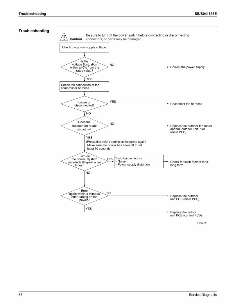
Troubleshooting SiUS041638E
Troubleshooting
Correct the power supply.
Replace the outdoor unit PCB (main PCB).
Check for such factors for a long term.
(R22370)
CautionBe sure to turn off the power switch before connecting or disconnecting connectors, or parts may be damaged.
NO
NO
YES
YES
NO
YES
YESReconnect the harness.
Check the power supply voltage.
Check the connection of the compressor harness.
Disturbance factors∗ Noise∗ Power supply distortion
(Precaution before turning on the power again) Make sure the power has been off for at least 30 seconds.
Replace the indoor unit PCB (control PCB).
Turn on the power. System
restarted? (Repeat a few times.)
Error again within 3 minutes
after turning on the power?
Loose or disconnected?
NO
YES
NOReplace the outdoor fan motor and the outdoor unit PCB (main PCB).
Does the outdoor fan rotate
smoothly?
Is the voltage fluctuation
within ±10% from the rated value?
65 Service Diagnosis
SiUS041638E Troubleshooting
4.7 Signal Transmission Error (between Indoor Unit and Outdoor Unit)
Error Code U4
Method of Error Detection
The signal transmission data from the outdoor unit is checked whether it is normal.
Error Decision Conditions
The data sent from the outdoor unit cannot be received normally, or the content of the data is abnormal.
Supposed Causes
Power supply voltage out of specificationReduction of power supply voltageWiring errorBreaking of the connecting wires between the indoor and outdoor units (wire No. 3)Defective outdoor unit PCBShort circuit inside the fan motor windingDefective indoor unit PCBDisturbed power supply waveform
Service Diagnosis 66
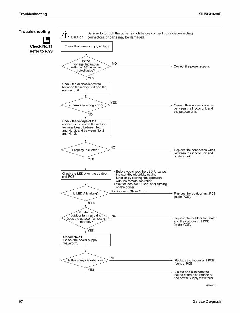
Troubleshooting SiUS041638E
Troubleshooting
Check No.11Refer to P.93
Check No.11Check the power supply waveform.
Check the voltage of the connection wires on the indoor terminal board between No. 1 and No. 3, and between No. 2 and No. 3.
YES
Blink
Replace the indoor unit PCB (control PCB).
Locate and eliminate the cause of the disturbance of the power supply waveform.
NO
(R24631)
Continuously ON or OFF
NO
YES
YES
NO
Caution
Correct the connection wires between the indoor unit and the outdoor unit.
Replace the outdoor unit PCB (main PCB).
Replace the connection wires between the indoor unit and outdoor unit.
Is LED A blinking?
Properly insulated?
Is there any disturbance?
Is there any wiring error?
Check the connection wires between the indoor unit and the outdoor unit.
Check the LED A on the outdoor unit PCB.
Be sure to turn off the power switch before connecting or disconnecting connectors, or parts may be damaged.
NO
YES
Check the power supply voltage.
Correct the power supply.
YES
NOReplace the outdoor fan motor and the outdoor unit PCB (main PCB).
Rotate the outdoor fan manually.
Does the outdoor fan rotate smoothly?
Is the voltage fluctuation
within ±10% from the rated value?
∗ Before you check the LED A, cancel the standby electricity saving function by starting fan operation with the remote controller.
∗ Wait at least for 15 sec. after turning on the power.
67 Service Diagnosis

SiUS041638E Troubleshooting
4.8 Signal Transmission Error on Outdoor Unit PCB
Error Code U7
Method of Error Detection
Communication error between microcomputer mounted on the main microcomputer and PM1.
Error Decision Conditions
The abnormality is determined when the data sent from the PM1 can not be received for 9 seconds. The error counter is reset when the data from the PM1 can be successfully received.
Supposed Causes
Defective outdoor unit PCB
Troubleshooting
(R21808)
Caution
YES
NO
Turn off the power. Then, turn on the power to restart the system.
Error again? The cause can be an external factor other than the malfunction.Observe the operating condition in long term.
Be sure to turn off the power switch before connecting or disconnecting connectors, or parts may be damaged.
Replace the outdoor unit PCB (main PCB).
Service Diagnosis 68
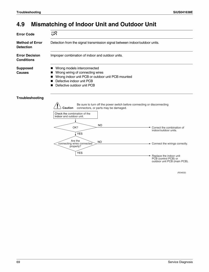
Troubleshooting SiUS041638E
4.9 Mismatching of Indoor Unit and Outdoor Unit
Error Code UA
Method of Error Detection
Detection from the signal transmission signal between indoor/outdoor units.
Error Decision Conditions
Improper combination of indoor and outdoor units.
Supposed Causes
Wrong models interconnectedWrong wiring of connecting wiresWrong indoor unit PCB or outdoor unit PCB mountedDefective indoor unit PCBDefective outdoor unit PCB
Troubleshooting
(R24632)
Caution
NO
YES
YES
NO
Correct the combination of indoor/outdoor units.
OK?
Connect the wirings correctly.
Replace the indoor unit PCB (control PCB) or outdoor unit PCB (main PCB).
Are the connecting wires connected
properly?
Check the combination of the indoor and outdoor unit.
Be sure to turn off the power switch before connecting or disconnecting connectors, or parts may be damaged.
69 Service Diagnosis
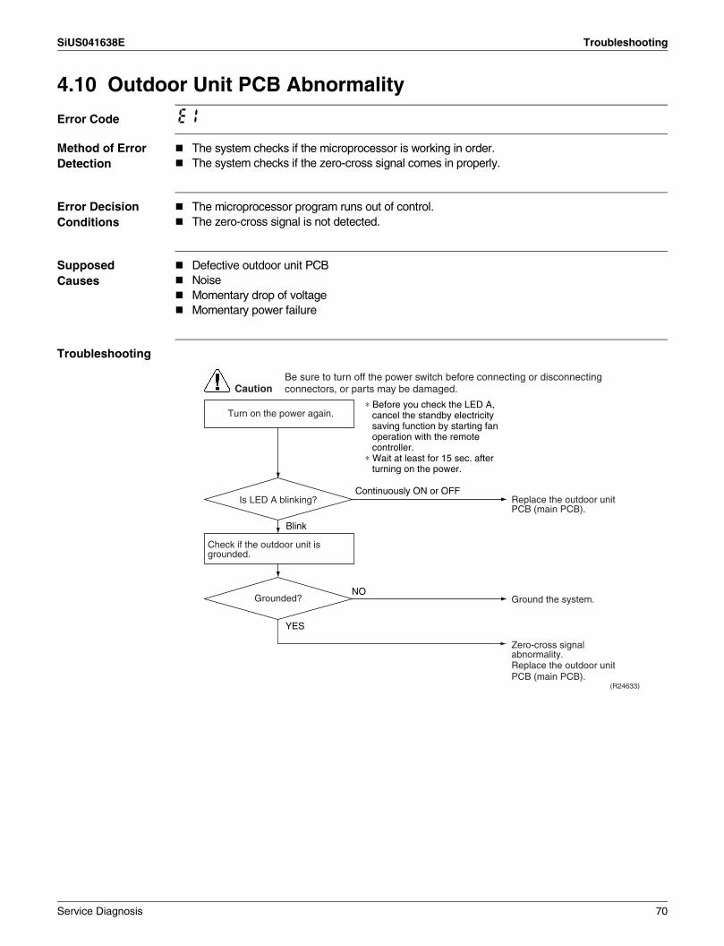
SiUS041638E Troubleshooting
4.10 Outdoor Unit PCB Abnormality
Error Code E1
Method of Error Detection
The system checks if the microprocessor is working in order.The system checks if the zero-cross signal comes in properly.
Error Decision Conditions
The microprocessor program runs out of control.The zero-cross signal is not detected.
Supposed Causes
Defective outdoor unit PCBNoiseMomentary drop of voltageMomentary power failure
Troubleshooting
CautionBe sure to turn off the power switch before connecting or disconnecting connectors, or parts may be damaged.
Continuously ON or OFF
Blink
YES
(R24633)
NO
Replace the outdoor unit PCB (main PCB).
Ground the system.
Zero-cross signal abnormality.Replace the outdoor unit PCB (main PCB).
Check if the outdoor unit is grounded.
Is LED A blinking?
Grounded?
Turn on the power again.∗ Before you check the LED A,
cancel the standby electricity saving function by starting fan operation with the remote controller.
∗ Wait at least for 15 sec. after turning on the power.
Service Diagnosis 70

Troubleshooting SiUS041638E
4.11 OL Activation (Compressor Overload)
Error Code E5
Method of Error Detection
A compressor overload is detected through compressor OL.
Error Decision Conditions
If the error repeats, the system is shut down.Reset condition: Continuous run for about 60 minutes without any other error
Supposed Causes
Disconnection of discharge pipe thermistorDefective discharge pipe thermistorDisconnection of connector S40Disconnection of 2 terminals of OL (Q1L)Defective OL (Q1L)Broken OL harnessDefective electronic expansion valve or coilDefective four way valve or coilDefective outdoor unit PCBRefrigerant shortageWater mixed in refrigerantDefective stop valve
71 Service Diagnosis

SiUS041638E Troubleshooting
Troubleshooting
Check No.01Refer to P.92
Check No.12Refer to P.94
Check No.13Refer to P.95
Check No.14Refer to P.95
Note: OL (Q1L) activating temperature: 130°C (266°F)OL (Q1L) recovery temperature: 95°C (203°F)
(R22976)
Caution
YES
NG
NO
OK
OK
NG
NG
OK
YES
NO
NG
OK
∗ Refrigerant shortage∗ Water mixed∗ Stop valve
Disconnect the connector S40 from the PCB.
Disconnect the 2 terminals of the OL (Q1L).
Resistance ∞
Resistance ∞
Nearly 0 Ω
Nearly 0 Ω
Insert the thermistor in position.
Replace the discharge pipe thermistor.
Replace the electronic expansion valve or the coil.
Refer to the refrigerant line check procedure.
Replace the outdoor unit PCB (main PCB).
Replace the four way valve or the coil.Replace the outdoor unit PCB (main PCB).
Discharge pipe thermistor disconnected?
Check No. 01Check the discharge pipe
thermistor.
Check No. 13Check the four way
valve.
Check No. 14Check the refrigerant
line.
Check No. 12Check the electronic
expansion valve.
Replace the OL (Q1L).
Replace the OL harness.
Connect the connector S40 properly.
Is the connector S40 properly connected?
Check the resistance
between the 2 terminals on connector S40.
Check the resistance between the 2 terminals of the OL
(Q1L).
Be sure to turn off the power switch before connecting or disconnecting connectors, or parts may be damaged.
Service Diagnosis 72
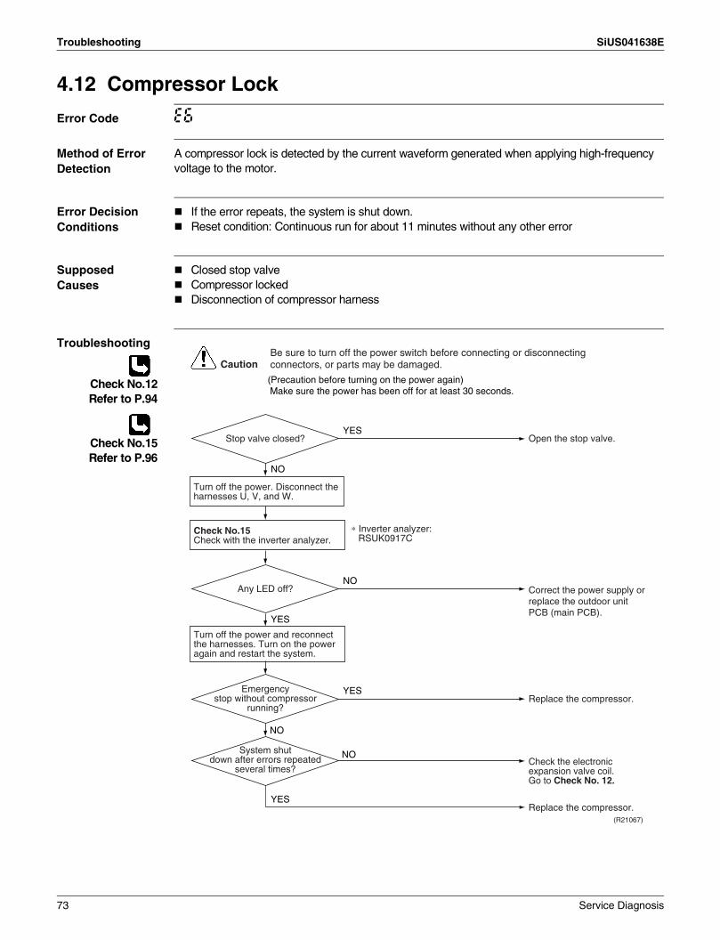
Troubleshooting SiUS041638E
4.12 Compressor Lock
Error Code E6
Method of Error Detection
A compressor lock is detected by the current waveform generated when applying high-frequency voltage to the motor.
Error Decision Conditions
If the error repeats, the system is shut down.Reset condition: Continuous run for about 11 minutes without any other error
Supposed Causes
Closed stop valveCompressor lockedDisconnection of compressor harness
Troubleshooting
Check No.12Refer to P.94
Check No.15Refer to P.96
Turn off the power. Disconnect the harnesses U, V, and W.
(R21067)
Caution
NO
YES
YES
NO
NO
YES
NO
YES
Check No.15Check with the inverter analyzer.
Turn off the power and reconnect the harnesses. Turn on the power again and restart the system.
(Precaution before turning on the power again)Make sure the power has been off for at least 30 seconds.
Correct the power supply or replace the outdoor unit PCB (main PCB).
Open the stop valve.
∗ Inverter analyzer: RSUK0917C
Replace the compressor.
Replace the compressor.
Check the electronic expansion valve coil.Go to Check No. 12.
Any LED off?
Stop valve closed?
Emergency stop without compressor
running?
System shut down after errors repeated
several times?
Be sure to turn off the power switch before connecting or disconnecting connectors, or parts may be damaged.
73 Service Diagnosis

SiUS041638E Troubleshooting
4.13 DC Fan Lock (Outdoor Fan)
Error Code E7
Method of Error Detection
An error is determined with the high-voltage fan motor rotation speed detected by the Hall IC.
Error Decision Conditions
The fan does not start in 15 ~ 30 seconds even when the fan motor is running.If the error repeats, the system is shut down.Reset condition: Continuous run for about 11 minutes without any other error
Supposed Causes
Disconnection of the fan motorForeign matter stuck in the fanDefective fan motorDefective outdoor unit PCB
Troubleshooting
Check No.16Refer to P.98
(R22877)
Caution
YES
YES
NO
YES
NO
NO
YES
NO
Turn on the power.
Rotate the fan.
Check No. 16Check the rotation pulse input on the outdoor unit PCB (main PCB).
Turn off the power and reconnect the connector.
Remove the foreign matter.
Replace the outdoor fan motor.
Replace the outdoor unit PCB (main PCB).
Fan motor connector disconnected?
Foreign matter in or around the fan?
Replace the outdoor fan motor.
Fan rotates smoothly?
Pulse signal generated?
Be sure to turn off the power switch before connecting or disconnecting connectors, or parts may be damaged.
Service Diagnosis 74
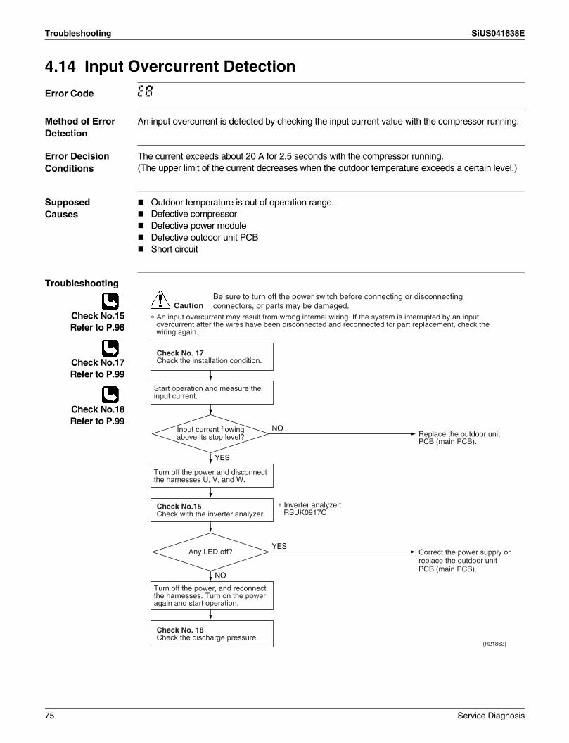
Troubleshooting SiUS041638E
4.14 Input Overcurrent Detection
Error Code E8
Method of Error Detection
An input overcurrent is detected by checking the input current value with the compressor running.
Error Decision Conditions
The current exceeds about 20 A for 2.5 seconds with the compressor running.(The upper limit of the current decreases when the outdoor temperature exceeds a certain level.)
Supposed Causes
Outdoor temperature is out of operation range.Defective compressorDefective power moduleDefective outdoor unit PCBShort circuit
Troubleshooting
Check No.15Refer to P.96
Check No.17Refer to P.99
Check No.18Refer to P.99
CautionBe sure to turn off the power switch before connecting or disconnecting connectors, or parts may be damaged.
∗ An input overcurrent may result from wrong internal wiring. If the system is interrupted by an input overcurrent after the wires have been disconnected and reconnected for part replacement, check the wiring again.
(R21863)
NO
YES
YES
NO
Start operation and measure the input current.
Check No. 18Check the discharge pressure.
Check No. 17Check the installation condition.
Check No.15Check with the inverter analyzer.
Turn off the power and disconnect the harnesses U, V, and W.
Turn off the power, and reconnect the harnesses. Turn on the power again and start operation.
Replace the outdoor unit PCB (main PCB).
Correct the power supply or replace the outdoor unit PCB (main PCB).
Any LED off?
Input current flowing above its stop level?
∗ Inverter analyzer: RSUK0917C
75 Service Diagnosis
SiUS041638E Troubleshooting
4.15 Four Way Valve Abnormality
Error Code EA
Method of Error Detection
The room temperature thermistor and the indoor heat exchanger thermistor are checked if they function within their normal ranges in each operation mode.
Error Decision Conditions
The following condition continues over 10 minutes after operating for 5 minutes.Cooling/DryA – B < –5°C (A – B < –9°F)HeatingB – A < –5°C (B – A < –9°F)
A: Room thermistor temperatureB: Indoor heat exchanger temperature
If the error repeats, the system is shut down.Reset condition: Continuous run for about 60 minutes without any other error
Supposed Causes
Disconnection of four way valve coilDefective four way valve, coil, or harnessDefective outdoor unit PCBDefective thermistor(s)Refrigerant shortageWater mixed in refrigerantDefective stop valve
Service Diagnosis 76
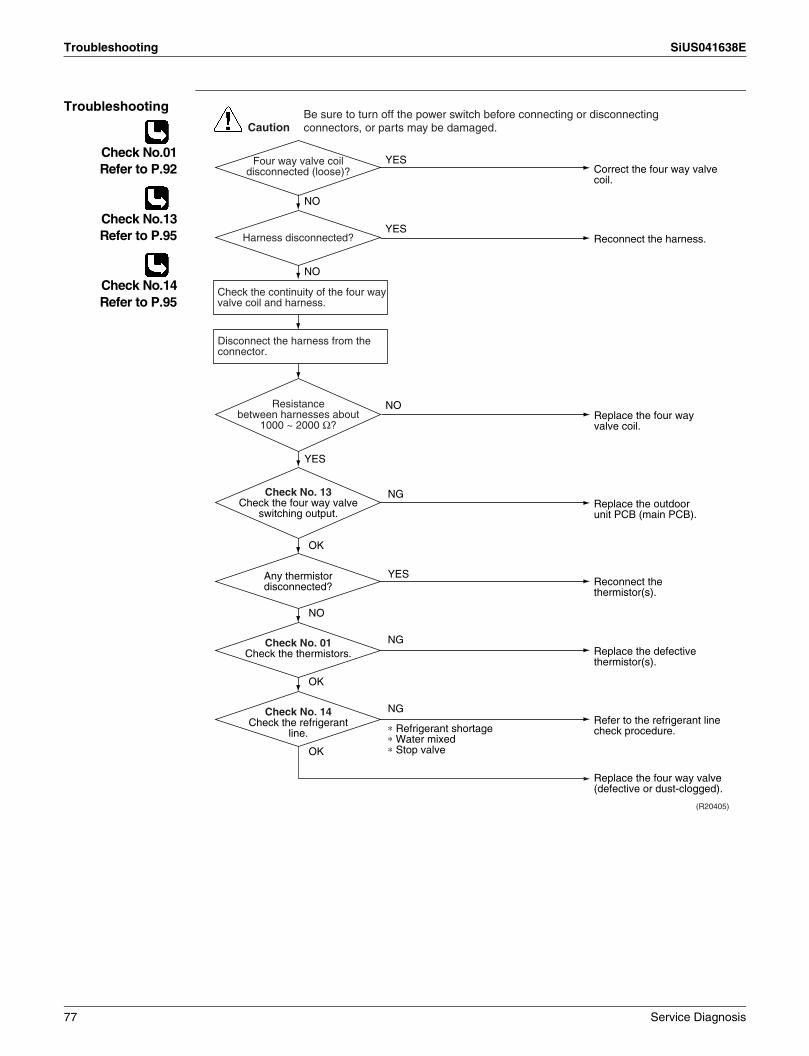
Troubleshooting SiUS041638E
Troubleshooting
Check No.01Refer to P.92
Check No.13Refer to P.95
Check No.14Refer to P.95
NG
OK
NO
OK
NG
OK
YES
NG
Correct the four way valve coil.
Reconnect the harness.
YES
YES
YES
NO
NO
Replace the outdoor unit PCB (main PCB).
Replace the defective thermistor(s).
Refer to the refrigerant line check procedure.
Replace the four way valve (defective or dust-clogged).
Reconnect the thermistor(s).
CautionBe sure to turn off the power switch before connecting or disconnecting connectors, or parts may be damaged.
(R20405)
∗ Refrigerant shortage∗ Water mixed∗ Stop valve
Four way valve coil disconnected (loose)?
Harness disconnected?
Any thermistor disconnected?
Check No. 01Check the thermistors.
Check No. 14Check the refrigerant
line.
Check No. 13Check the four way valve
switching output.
Check the continuity of the four way valve coil and harness.
Replace the four way valve coil.
NOResistance between harnesses about
1000 ~ 2000 Ω?
Disconnect the harness from the connector.
77 Service Diagnosis

SiUS041638E Troubleshooting
4.16 Discharge Pipe Temperature Control
Error Code F3
Method of Error Detection
An error is determined with the temperature detected by the discharge pipe thermistor.
Error Decision Conditions
If the temperature detected by the discharge pipe thermistor rises above A, the compressor stops.The error is cleared when the discharge pipe temperature has dropped below B.
RK(X)30/36NMVJU
If the error repeats, the system is shut down.Reset condition: Continuous run for about 60 minutes without any other error
Supposed Causes
Defective discharge pipe thermistor(Defective outdoor heat exchanger thermistor or outdoor temperature thermistor)Defective electronic expansion valve or coilRefrigerant shortageDefective four way valveWater mixed in refrigerantDefective stop valveDefective outdoor unit PCB
Troubleshooting
Check No.01Refer to P.92
Check No.12Refer to P.94
Check No.14Refer to P.95
A B
°C °F °C °F
120 248 107 224.6
(R20417)
Caution
NG
OK
OK
OK
NG
NG
∗ Discharge pipe thermistor∗ Outdoor heat exchanger thermistor∗ Outdoor temperature thermistor
∗ Refrigerant shortage∗ Four way valve∗ Water mixed∗ Stop valve
Check No. 12Check the electronic
expansion valve.
Replace the defective thermistor(s).
Replace the electronic expansion valve or the coil.
Refer to the refrigerant line check procedure.
Replace the outdoor unit PCB (main PCB).
Be sure to turn off the power switch before connecting or disconnecting connectors, or parts may be damaged.
Check No. 01Check the thermistors.
Check No. 14Check the refrigerant line.
Service Diagnosis 78

Troubleshooting SiUS041638E
4.17 High Pressure Control in Cooling
Error Code F6
Method of Error Detection
High-pressure control (operation halt, frequency drop, etc.) is activated in cooling operation if the temperature sensed by the outdoor heat exchanger thermistor exceeds the limit.
Error Decision Conditions
The temperature sensed by the outdoor heat exchanger thermistor rise above 60°C (140°F).The error is cleared when the temperature drops below 47°C (116.6°F).
Supposed Causes
Installation space not large enoughDirty outdoor heat exchangerDefective outdoor fan motorDefective stop valveDefective electronic expansion valve or coilDefective outdoor heat exchanger thermistorDefective outdoor unit PCB
Troubleshooting
Check No.01Refer to P.92
Check No.12Refer to P.94
Check No.17Refer to P.99
Check No.18Refer to P.99
Check No.19Refer to P.100
(R20418)
Caution
Replace the outdoor fan motor.Reconnect the connector or fan motor lead wires.
Replace the stop valve.
Replace the outdoor heat exchanger thermistor.
Replace the outdoor unit PCB (main PCB).
Replace the electronic expansion valve or the coil.Replace the outdoor unit PCB (main PCB).
Change the installation location or direction.Clean the outdoor heat exchanger.
Check the installation space.
NG
OK
OK
NG
NG
OK
OK
OK
NG
NG
Check No. 19Check the outdoor fan.
Check No. 18Check the discharge
pressure.
Check No. 12Check the electronic
expansion valve.
Check No. 01Check the outdoor heat exchanger thermistor.
Check No. 17Check the installation
condition.
Be sure to turn off the power switch before connecting or disconnecting connectors, or parts may be damaged.
79 Service Diagnosis

SiUS041638E Troubleshooting
4.18 System Shutdown due to Compressor Internal Temperature Abnormality
Error Code F8
Method of Error Detection
Operation is halted when the temperature detected by the discharge pipe thermistor exceeds the determined limit.
Error Decision Conditions
Temperature exceeds the detection threshold of 127.5°C during forced cooling operation.
Supposed Causes
Abnormal operation due to air intrusionDefective discharge pipe thermistor
Troubleshooting
Check No.01Refer to P.92
YES
(R23655)
NO
OK
NG
Caution
Replace the outdoor unit.
Replace both the discharge pipe thermistor and the outdoor unit PCB (main PCB).
Replace the outdoor unit.
Abnormal deformation of piping in the
outdoor unit
Check No. 01 Check the discharge pipe
thermistor
Be sure to turn off the power switch before connecting or disconnecting connectors, or parts may be damaged.
Replace the unit as directed in the installation manual, making sure that air does not intrude into the refrigerant pipings.
Service Diagnosis 80
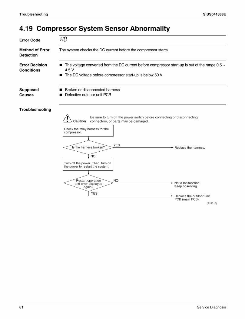
Troubleshooting SiUS041638E
4.19 Compressor System Sensor Abnormality
Error Code H0
Method of Error Detection
The system checks the DC current before the compressor starts.
Error Decision Conditions
The voltage converted from the DC current before compressor start-up is out of the range 0.5 ~ 4.5 V.The DC voltage before compressor start-up is below 50 V.
Supposed Causes
Broken or disconnected harness Defective outdoor unit PCB
Troubleshooting
CautionBe sure to turn off the power switch before connecting or disconnecting connectors, or parts may be damaged.
NO
(R22016)
YES
Turn off the power. Then, turn on the power to restart the system.
YES
NO
Replace the harness.
Replace the outdoor unit PCB (main PCB).
Is the harness broken?
Restart operation and error displayed
again?
Check the relay harness for the compressor.
Not a malfunction.Keep observing.
81 Service Diagnosis

SiUS041638E Troubleshooting
4.20 Position Sensor Abnormality
Error Code H6
Method of Error Detection
A compressor start-up failure is detected by checking the compressor running condition through the position detection circuit.
Error Decision Conditions
If the error repeats, the system is shut down.Reset condition: Continuous run for about 11 minutes without any other error
Supposed Causes
Power supply voltage out of specificationDisconnection of the compressor harnessDefective compressorDefective outdoor unit PCBStart-up failure caused by the closed stop valveInput voltage out of specified range
Service Diagnosis 82

Troubleshooting SiUS041638E
Troubleshooting
Check No.15Refer to P.96
Check No.18Refer to P.99
Check No.20Refer to P.100
CautionBe sure to turn off the power switch before connecting or disconnecting connectors, or parts may be damaged.
NO
YES
Turn off the power.
Check the connection.
Check the power supply voltage.
Correct the power supply.Voltage as rated?
(R21864)
NO
NO
NO
NO
YES
YES
YES
YES
Check No. 20Check the short circuit of the diode bridge.
Check No.15Check with the inverter analyzer.
Turn off the power. Disconnect the harnesses U, V, and W.
Turn on the power. Check the electrolytic capacitor voltage.
Electrical components or
compressor harnesses connected as
specified?
Replace the outdoor unit PCB (main PCB).
Correct the power supply or replace the outdoor unit PCB (main PCB).
Replace the compressor.
Reconnect the electrical components or compressor harnesses as specified.
Replace the outdoor unit PCB (main PCB).
∗ Inverter analyzer: RSUK0917C
Normal?
NO
YES
Check No. 18Check the discharge pressure.
Replace the stop valve.OK?
320 VDC?
Any LED OFF?
+ 100 - 50
83 Service Diagnosis
SiUS041638E Troubleshooting
4.21 CT or Related Abnormality
Remote Controller Display
H8
Method of Malfunction Detection
A CT or related error is detected by checking the compressor running frequency and CT-detected input current.
Malfunction Decision Conditions
The compressor running frequency is more than A Hz, and the CT input current is less than B A.
If the error repeats, the system is shut down.Reset condition: Continuous run for about 60 minutes without any other error
Supposed Causes
Defective power moduleBroken or disconnected wiringDefective reactorDefective outdoor unit PCB
A (Hz) B (A)
32 0.5
Service Diagnosis 84
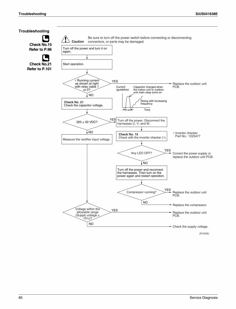
Troubleshooting SiUS041638E
Troubleshooting
Check No.15Refer to P.96
Check No.21Refer to P.101
(R15326)
Caution
YES
2 sec Time
NO
NO
YES
YES
NO
YES
NO
YES
NO
Current (guideline)
Turn off the power and turn it on again.
Start operation.
Check No. 21Check the capacitor voltage.
Measure the rectifier input voltage.
Turn off the power. Disconnect the harnesses U, V, and W.
Check No. 15Check with the inverter checker (∗).
Turn off the power and reconnect the harnesses. Then turn on the power again and restart operation.
Replace the outdoor unit PCB.
Replace the outdoor unit PCB.
Replace the outdoor unit PCB.
Check the supply voltage.
Replace the compressor.
Capacitor charged when the indoor unit or outdoor unit main relay turns on
Rising with increasing frequency
Correct the power supply or replace the outdoor unit PCB.
∗ Inverter checker Part No.: 1225477
Be sure to turn off the power switch before connecting or disconnecting connectors, or parts may be damaged.
∗ Running current as shown at right with relay cable 1
or 2?
320 ± 50 VDC?
Any LED OFF?
Compressor running?
Voltage within the allowable range
(Supply voltage ± 15%)?
85 Service Diagnosis
SiUS041638E Troubleshooting
4.22 Thermistor or Related Abnormality (Outdoor Unit)
Error Code H9, J3, J6, P4
Method of Error Detection
This fault is identified based on the thermistor input voltage to the microcomputer.A thermistor fault is identified based on the temperature sensed by each thermistor.
Error Decision Conditions
The voltage between the both ends of the thermistor is either 4.96 V or more, or 0.04 V or less with the power on.J3 error is judged if the discharge pipe temperature is lower than the heat exchanger temperature.
Supposed Causes
Disconnection of the connector for the thermistorDefective thermistor(s)Defective heat exchanger thermistor in the case of J3 error (outdoor heat exchanger thermistor in cooling operation, or indoor heat exchanger thermistor in heating operation)Defective outdoor unit PCB
Troubleshooting In case of P4
Replace the outdoor unit PCB (main PCB).
P4 : Radiation fin thermistor
CautionBe sure to turn off the power switch before connecting or disconnecting connectors, or parts may be damaged.
Service Diagnosis 86

Troubleshooting SiUS041638E
Troubleshooting In case of H9, J3, J6
Check No.01Refer to P.92
H9 : Outdoor temperature thermistorJ3 : Discharge pipe thermistorJ6 : Outdoor heat exchanger thermistor
Note: When replacing the defective thermistor(s), replace the thermistors as ASSY.
(R20406)
Caution
NO
YES
YES
NO
NO
YES
Turn on the power again.
Normal?
Reconnect the connectors or thermistors.
J3 error: the discharge pipe temperature is lower than the heat exchanger temperature.
Replace the defective thermistor(s) of the following thermistors.
∗ Outdoor temperature thermistor
∗ Discharge pipe thermistor∗ Outdoor heat exchanger
thermistorCooling: Outdoor heat
exchanger temperature
Heating: Indoor heat exchanger temperature
Replace the indoor heat exchanger thermistor.
Replace the outdoor unit PCB (main PCB).
Error displayed again on remote
controller?
Indoor heat exchanger thermistor
functioning?
Check No. 01Check the thermistor resistance value.
Check No. 01Check the indoor heat exchanger thermistor resistance value in the heating operation.
Be sure to turn off the power switch before connecting or disconnecting connectors, or parts may be damaged.
87 Service Diagnosis

SiUS041638E Troubleshooting
4.23 Electrical Box Temperature Rise
Error Code L3
Method of Error Detection
An electrical box temperature rise is detected by checking the radiation fin thermistor with the compressor off.
Error Decision Conditions
With the compressor off, the radiation fin temperature is above A.The error is cleared when the radiation fin temperature drops below B.To cool the electrical components, the outdoor fan starts when the radiation fin temperature rises above C and stops when it drops below B.
Supposed Causes
Defective outdoor fan motorShort circuitDefective radiation fin thermistorDisconnection of connectorDefective outdoor unit PCB
Troubleshooting
Check No.17Refer to P.99
Check No.19Refer to P.100
A B C
°C °F °C °F °C °F
RK(X)30/36NMVJU 92 197.6 70 158 77 170.6
Caution
WARNINGTo cool the electrical components, the outdoor fan starts when the radiation fin temperature rises above C and stops when the radiation fin temperature drops below B.
(R22998)
YES
NO
YES
NG
NO
OK
NO
YES
Turn off the power. Then, turn on the power to restart the system.
Check the radiation fin temperature.
Radiation fin dirty?
Check No. 19Check the outdoor fan.
Error again or outdoor fan activated?
Replace the outdoor unit PCB (main PCB).
Clean up the radiation fin.
Be sure to turn off the power switch before connecting or disconnecting connectors, or parts may be damaged.
Replace the outdoor fan motor.Correct the connectors and fan motor lead wire.Replace the outdoor unit PCB (main PCB).
Above A?
Check the installation condition.Go to Check No. 17.
Service Diagnosis 88

Troubleshooting SiUS041638E
4.24 Radiation Fin Temperature Rise
Error Code L4
Method of Error Detection
A radiation fin temperature rise is detected by checking the radiation fin thermistor with the compressor on.
Error Decision Conditions
If the radiation fin temperature with the compressor on is above A.The error is cleared when the radiation fin temperature drops below B.If the error repeats, the system is shut down.Reset condition: Continuous run for about 60 minutes without any other error
Supposed Causes
Defective outdoor fan motorShort circuitDefective radiation fin thermistorDisconnection of connectorDefective outdoor unit PCBSilicone grease not applied properly on the radiation fin after replacing the outdoor unit PCB
Troubleshooting
Check No.17Refer to P.99
Check No.19Refer to P.100
Note: Refer to Silicone Grease on Power Transistor/Diode Bridge on page 111 for details.
A B
°C °F °C °F
RK(X)30/36NMVJU 82 179.6 77 170.6
Caution
Turn off the power. Then, turn on the power to restart the system.
Be sure to turn off the power switch before connecting or disconnecting connectors, or parts may be damaged.
(R23953)
NO
NG
OK
NO
YES
Check the radiation fin temperature.
NO
YESYES
Above A?
Check No. 19Check the outdoor fan.
Error displayed again? Has the PCB been replaced? Check if silicone grease is
applied properly on the radiation fin. If not, apply the silicone grease.
Replace the outdoor unit PCB (main PCB).
Replace the outdoor fan motor.Correct the connectors and fan motor leads.Replace the outdoor unit PCB (main PCB).
YES
NORadiation fin dirty?
Clean up the radiation fin.
Check the installation condition.Go to Check No. 17.
89 Service Diagnosis
SiUS041638E Troubleshooting
4.25 Output Overcurrent Detection
Error Code L5
Method of Error Detection
An output overcurrent is detected by checking the current that flows in the inverter DC section.
Error Decision Conditions
A position signal error occurs while the compressor is running.A rotation speed error occurs while the compressor is running.An output overcurrent signal is fed from the output overcurrent detection circuit to the microcomputer.If the error repeats, the system is shut down.Reset condition: Continuous run for about 11 minutes without any other error
Supposed Causes
Poor installation conditionClosed stop valveDefective power moduleWrong internal wiringAbnormal power supply voltageDefective outdoor unit PCBPower supply voltage out of specificationDefective compressor
Service Diagnosis 90

Troubleshooting SiUS041638E
Troubleshooting
Check No.15Refer to P.96
Check No.17Refer to P.99
Check No.18Refer to P.99
Check No.22Refer to P.101
(R22566)
Caution
NO
YES
NO
YES
NO
YES
NO
YES
NO
YES
YES
NO
∗ An output overcurrent may result from wrong internal wiring. If the system is interrupted by an output overcurrent after the wires have been disconnected and reconnected for part replacement, check the wiring again.
Check No. 22
Check No. 17
Check No.15
Turn off the power and disconnect the harnesses U, V, and W.
Turn off the power, and reconnect the harnesses. Turn on the power again and start operation.
Turn off the power. Then, turn on the power to restart the system. See if the same error occurs.
Check the power supply voltage.
Monitor the power supply voltage, discharge and suction pressures, and other factors for a long term.
Possible causes∗ Momentary drop of power supply
voltage∗ Compressor overload∗ Short circuit
Check the installation condition.
Check with the inverter analyzer.
Check the power module.
Not a malfunction.Keep observing.Check the connectors and other components.
Fully open the stop valve.
Correct the power supply.
Replace the compressor.
Correct the power supply or replace the outdoor unit PCB (main PCB).
Replace the outdoor unit PCB (main PCB).
Error again?
Stop valve fully open?
Any LED off?
Normal?
∗ Inverter analyzer: RSUK0917C
Short circuit or wire breakage between
compressor's coil phases?
Be sure to turn off the power switch before connecting or disconnecting connectors, or parts may be damaged.
Check the discharge pressure.Go to Check No. 18.
Is the voltage fluctuation
within ±10% from the rated value?
91 Service Diagnosis
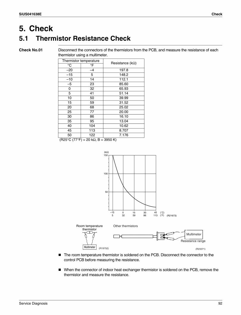
SiUS041638E Check
5. Check5.1 Thermistor Resistance Check
Check No.01 Disconnect the connectors of the thermistors from the PCB, and measure the resistance of each thermistor using a multimeter.
The room temperature thermistor is soldered on the PCB. Disconnect the connector to the control PCB before measuring the resistance.
When the connector of indoor heat exchanger thermistor is soldered on the PCB, remove the thermistor and measure the resistance.
Thermistor temperatureResistance (kΩ)
°C °F–20 –4 197.8 –15 5 148.2 –10 14 112.1 –5 23 85.60 0 32 65.93 5 41 51.14
10 50 39.99 15 59 31.52 20 68 25.02 25 77 20.00 30 86 16.10 35 95 13.04 40 104 10.62 45 113 8.707 50 122 7.176
(R25°C (77°F) = 20 kΩ, B = 3950 K)
(R21673)(˚C)
(kΩ)
–15 0 15 30 45
150
100
50
(˚F)5 32 59 86 113
Multimeter
Resistance range
Other thermistors
(R23371)Multimeter (R19752)
Room temperature thermistor
Service Diagnosis 92
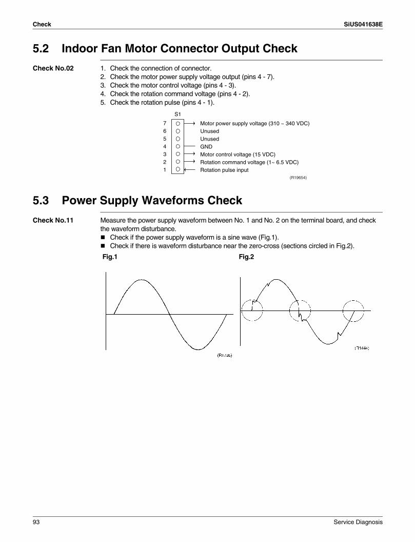
Check SiUS041638E
5.2 Indoor Fan Motor Connector Output Check
Check No.02 1. Check the connection of connector.2. Check the motor power supply voltage output (pins 4 - 7).3. Check the motor control voltage (pins 4 - 3).4. Check the rotation command voltage (pins 4 - 2).5. Check the rotation pulse (pins 4 - 1).
5.3 Power Supply Waveforms Check
Check No.11 Measure the power supply waveform between No. 1 and No. 2 on the terminal board, and check the waveform disturbance.
Check if the power supply waveform is a sine wave (Fig.1).Check if there is waveform disturbance near the zero-cross (sections circled in Fig.2).
7654321
S1
(R19654)
Motor power supply voltage (310 ~ 340 VDC)UnusedUnusedGNDMotor control voltage (15 VDC)Rotation command voltage (1~ 6.5 VDC)Rotation pulse input
Fig.1 Fig.2
93 Service Diagnosis

SiUS041638E Check
5.4 Electronic Expansion Valve Check
Check No.12 Conduct the following to check the electronic expansion valve (EV).1. Check if the EV connector is correctly connected to the PCB.2. Turn the power off and on again, and check to see if the EV generates a latching sound.3. If the EV does not generate a latching sound in the above step 2, disconnect the connector and
check the continuity using a multimeter.4. Check the continuity between the pins 5 - 1, 5 - 2, 5 - 3, 5 - 4. If there is no continuity between
the pins, the EV coil is faulty.5. If the continuity is confirmed in step 3, the outdoor unit PCB (main PCB) is faulty.
Harness 5P
5P Connector CheckS20
5 - 15 - 25 - 35 - 4
1 2 3 4 5(R23840)
Service Diagnosis 94
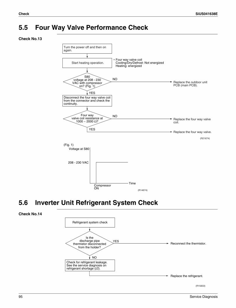
Check SiUS041638E
5.5 Four Way Valve Performance Check
Check No.13
5.6 Inverter Unit Refrigerant System Check
Check No.14
(R21674)
NO
YES
YES
NO
Turn the power off and then on again.
Disconnect the four way valve coil from the connector and check the continuity.
Start heating operation.∗ Four way valve coil
Cooling/Dry/Defrost: Not energizedHeating: energized
Replace the outdoor unit PCB (main PCB).
Replace the four way valve coil.
Replace the four way valve.
Four way valve coil resistance at
1000 ~ 2000 Ω?
S80 voltage at 208 - 230
VAC with compressor on? (Fig. 1)
(R14674)
(Fig. 1)
Compressor ON
Voltage at S80
208 - 230 VAC
Time
Refrigerant system check
Check for refrigerant leakage.See the service diagnosis on refrigerant shortage (U0).
(R15833)
YES
NO
Reconnect the thermistor.
Replace the refrigerant.
Is the discharge pipe
thermistor disconnected from the holder?
95 Service Diagnosis
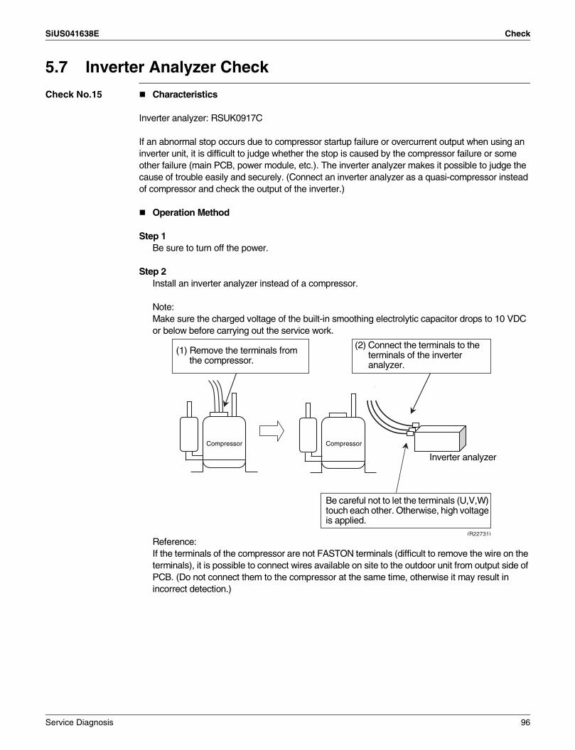
SiUS041638E Check
5.7 Inverter Analyzer Check
Check No.15 Characteristics
Inverter analyzer: RSUK0917C
If an abnormal stop occurs due to compressor startup failure or overcurrent output when using an inverter unit, it is difficult to judge whether the stop is caused by the compressor failure or some other failure (main PCB, power module, etc.). The inverter analyzer makes it possible to judge the cause of trouble easily and securely. (Connect an inverter analyzer as a quasi-compressor instead of compressor and check the output of the inverter.)
Operation Method
Step 1Be sure to turn off the power.
Step 2Install an inverter analyzer instead of a compressor.
Note:Make sure the charged voltage of the built-in smoothing electrolytic capacitor drops to 10 VDC or below before carrying out the service work.
Reference:If the terminals of the compressor are not FASTON terminals (difficult to remove the wire on the terminals), it is possible to connect wires available on site to the outdoor unit from output side of PCB. (Do not connect them to the compressor at the same time, otherwise it may result in incorrect detection.)
(R22731)
(1) Remove the terminals from the compressor.
(2) Connect the terminals to the terminals of the inverter analyzer.
Compressor
Inverter analyzer
Be careful not to let the terminals (U,V,W) touch each other. Otherwise, high voltage is applied.
Compressor
Service Diagnosis 96

Check SiUS041638E
Step 3Activate power transistor test operation from the indoor unit.
(1) Turn the power on.(2) Select FAN operation with the Mode button on the remote controller.(3) Press the center of the Temp button and the Mode button at the same time.(4) Select T with the Temp or Temp button.(5) Press the Mode button to start the power transistor test operation.
Diagnose method (Diagnose according to 6 LEDs lighting status of inverter analyzer.)(1) If all the LEDs are lit uniformly, the compressor is defective.
→ Replace the compressor.(2) If the LEDs are not lit uniformly, check the power module.
→ Refer to Check No.22.(3) If NG in Check No.22, replace the power module.
(Replace the main PCB. The power module is united with the main PCB.)If OK in Check No.22, check if there is any solder cracking on the PCB.
(4) If any solder cracking is found, replace the PCB or repair the soldered section.If there is no solder cracking, replace the PCB.
Caution(1) When the output frequency is low, the LEDs blink slowly. As the output frequency increases, the
LEDs blink quicker. (The LEDs look like they are lit.)(2) On completion of the inverter analyzer diagnosis, be sure to re-crimp the FASTON terminals.
Otherwise, the terminals may be burned due to loosening.
(R24537)
(R15292)
Direction of crimp
FASTON terminal
This size is shortened
by the crimp.
97 Service Diagnosis

SiUS041638E Check
5.8 Rotation Pulse Check on the Outdoor Unit PCB
Check No.16 Make sure that the voltage of 320 + 100 V ~ 320 - 50 V is applied.1. Set operation off and power off. Disconnect the connector S70 or S71.2. Check that the voltage between the pins 4 - 7 is 320 VDC.3. Check that the control voltage between the pins 4 - 3 is 15 VDC.4. Check that the rotation command voltage between the pins 4 - 2 is 0 ~ 6.5 VDC.5. Keep operation off and power off. Connect the connector S70 or S71.6. Check whether 4 rotation pulses (0 ~ 15 VDC) are input at the pins 4 - 1 when the fan motor is
rotated 1 turn by hand.
When the fuse is melted, check the outdoor fan motor for proper function.If NG in step 2 → Defective PCB → Replace the outdoor unit PCB (main PCB).If NG in step 4 → Defective Hall IC → Replace the outdoor fan motor.If OK in both steps 2 and 4 → Replace the outdoor unit PCB (main PCB).
1
2
3
4
5
6
7 320 VDC
(R19655)
S70
PCB
Actual rotation pulse input (0 ~ 15 VDC)
Rotation command voltage (0 ~ 6.5 VDC)
Control voltage 15 VDC
Service Diagnosis 98
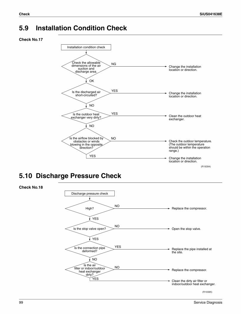
Check SiUS041638E
5.9 Installation Condition Check
Check No.17
5.10 Discharge Pressure Check
Check No.18
Installation condition check
OK
Check the allowable dimensions of the air
suction and discharge area.
Is the airflow blocked by obstacles or winds
blowing in the opposite direction?
(R19394)
NG
YES
YES
NO
Is the discharged air short-circuited?
NO
NO
YES
Is the outdoor heat exchanger very dirty?
Change the installation location or direction.
Change the installation location or direction.
Clean the outdoor heat exchanger.
Change the installation location or direction.
Check the outdoor temperature. (The outdoor temperature should be within the operation range.)
(R19385)
YES
YES
YES
NO
NO
NO
NO
YES
Is the air filter or indoor/outdoor
heat exchanger dirty?
Is the connection pipe deformed?
Is the stop valve open?
High? Replace the compressor.
Open the stop valve.
Replace the pipe installed at the site.
Clean the dirty air filter or indoor/outdoor heat exchanger.
Replace the compressor.
Discharge pressure check
99 Service Diagnosis

SiUS041638E Check
5.11 Outdoor Fan System Check
Check No.19 DC motor
5.12 Main Circuit Short Check
Check No.20 Check to make sure that the voltage between (+) and (–) of the diode bridge (DB1) is approximately 0 V before checking.
Measure the resistance between the pins of the DB1 referring to the table below.If the resistance is ∞ or less than 1 kΩ, short circuit occurs on the main circuit.
RK(X)30/36NMVJU
(R21195)
YES
NONO
YES
Outdoor fan system is functioning.
Check the outdoor fan system.
Reconnect the connector.
Is theoutdoor fan running?
Fan motor lead wire connector
disconnected?Go to Check No. 16.
Positive terminal (+) of digital multimeter ~ (2, 3) + (4) ~ (2, 3) – (1)
Negative terminal (–) of digital multimeter + (4) ~ (2, 3) – (1) ~ (2, 3)
Resistance is OK. several kΩ ~ several MΩResistance is NG. 0 Ω or ∞
(R24538)
1
2
3
4
Multimeter
–~
~+
–+
Service Diagnosis 100

Check SiUS041638E
5.13 Capacitor Voltage Check
Check No.21 Before this check, be sure to check the main circuit for short circuit.With the circuit breaker still on, measure the voltage according to the drawing of the model in question. Be careful never to touch any live parts.
To prevent an electrical shock, use a multimeter to check that the voltage between FU2 and DC– is 50 V or less.The surface of the test points (DC–) may be covered with the coating. Be sure to make firm contact between the multimeter probes and the test points.
5.14 Power Module Check
Check No.22 Check to make sure that the voltage between (+) and (–) of the power module is approximately 0 V before checking.
Disconnect the compressor harness connector from the outdoor unit PCB. To disengage the connector, press the protrusion on the connector.Follow the procedure below to measure resistance between the terminals of the power module and the terminals of the compressor with a multimeter. Evaluate the measurement results referring to the following table.
(R21938)
Multimeter (DC. voltage range)
FU2 DC– Coating
PCB
Multimeter probe
(R21939)
Positive terminal (+) of digital multimeter
Power module (+)
UVW Power module (–)
UVW
Negative terminal (–) of digital multimeter
UVW Power module (+)
UVW Power module (–)
Resistance is OK. several kΩ ~ several MΩResistance is NG. 0 Ω or ∞
101 Service Diagnosis
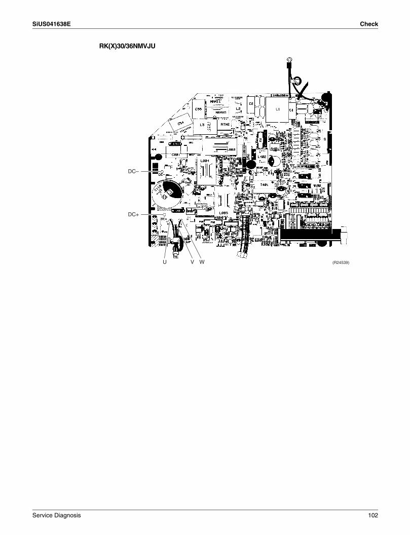
SiUS041638E Check
RK(X)30/36NMVJU
(R24539)
DC–
DC+
WVU
Service Diagnosis 102
SiUS041638E
103 Trial Operation and Field Settings
Part 7Trial Operation and
Field Settings1. Pump Down Operation............................................................................1042. Forced Cooling Operation .......................................................................1053. Trial Operation ........................................................................................1064. Field Settings ..........................................................................................107
4.1 Model Type Setting .................................................................................. 1074.2 Temperature Display Switch .................................................................... 1074.3 When 2 Units are Installed in 1 Room...................................................... 1084.4 Facility Setting Switch (cooling at low outdoor temperature).................... 109
5. Silicone Grease on Power Transistor/Diode Bridge................................111

SiUS041638E Pump Down Operation
1. Pump Down OperationOutline In order to protect the environment, be sure to conduct pump down operation when relocating or
disposing of the unit.
Details 1. Remove the valve caps from the liquid stop valve and the gas stop valve.2. Carry out forced cooling operation.3. After 5 to 10 minutes, close the liquid stop valve with a hexagonal wrench.4. After 2 to 3 minutes, close the gas stop valve and stop the forced cooling operation.5. Attach the valve cap once procedures are complete.
Refer to forced cooling operation on page 105.
Gas stop valve Valve cap
Close
Liquid stop valve
Service port (R13628)
Hexagonal wrench
Trial Operation and Field Settings 104

Forced Cooling Operation SiUS041638E
2. Forced Cooling OperationOutline The forced cooling operation is allowed when both the following conditions are met.
1) The outdoor unit is not abnormal and not in the 3-minute standby mode.2) The outdoor unit is not operating.
Protection functions have priority over all other functions during forced cooling operation.
Procedure With the indoor unit ON/OFF buttonPress the indoor unit ON/OFF button for at least 5 seconds. (The operation will start.)
Forced cooling operation will stop automatically after about 15 minutes. To stop the operation, press the indoor unit ON/OFF button.
With the indoor unit’s remote controller(1) Press Mode button and select the cooling operation.(2) Press On/Off button to turn on the system.(3) Press Temp , buttons and Mode button at the same time.(4) Press Temp , buttons, select “ T ”, and press Mode button for confirmation.
Forced cooling operation will stop automatically after about 30 minutes. To stop the operation, press On/Off button.
Indoor Unit Remote Controller
Indoor unit ON/OFF button(R24540)
(R24541)(1) (3) (4)
(2)
(3) (4)
(4)
105 Trial Operation and Field Settings

SiUS041638E Trial Operation
3. Trial OperationOutline 1. Measure the supply voltage and make sure that it is within the specified range.
2. In cooling operation, select the lowest programmable temperature; in heating operation, select the highest programmable temperature.
3. Carry out the trial operation following the instructions in the operation manual to ensure that all functions and parts, such as the movement of the flaps, are working properly.
To protect the air conditioner, restart operation is disabled for 3 minutes after the system has been turned off.
4. After trial operation is complete, set the temperature to a normal level (78°F to 82°F (26°C to 28°C) in cooling operation, 68°F to 75°F (20°C to 24°C) in heating operation).
Procedure When operating the air conditioner in cooling operation in winter, or heating operation in summer, set it to the trial operation mode using the following method.
With remote controller(1) Press On/Off button to turn on the system.(2) Press the center of Temp button and Mode button at the same time.(3) Select “ T ” (trial operation) with Temp or Temp button.(4) Press Mode button to start the trial operation.(5) Press Mode button and select operation mode.(6) Trial operation will stop automatically after about 30 minutes.
To stop trial operation, press On/Off button.
Test Items
(2) (4) (5)
(1) (6)
(2) (3)
(3)
(R24542)
Test items Symptom
Indoor and outdoor units are installed securely. Fall, vibration, noise
No refrigerant gas leaks. Incomplete cooling/heating function
Refrigerant gas and liquid pipes and indoor drain hose extension are thermally insulated. Water leakage
Draining line is properly installed. Water leakage
System is properly grounded. Electrical leakage
Only specified wires are used for all wiring, and all wires are connected correctly. No operation or burn damage
Indoor or outdoor unit’s air inlet or air outlet are unobstructed. Incomplete cooling/heating function
Stop valves are opened. Incomplete cooling/heating function
Indoor unit properly receives remote controller commands. No operation
Remote controller jumper setting is correct for the type of unit (heat pump or cooling only). Remote controller malfunctioning
Trial Operation and Field Settings 106
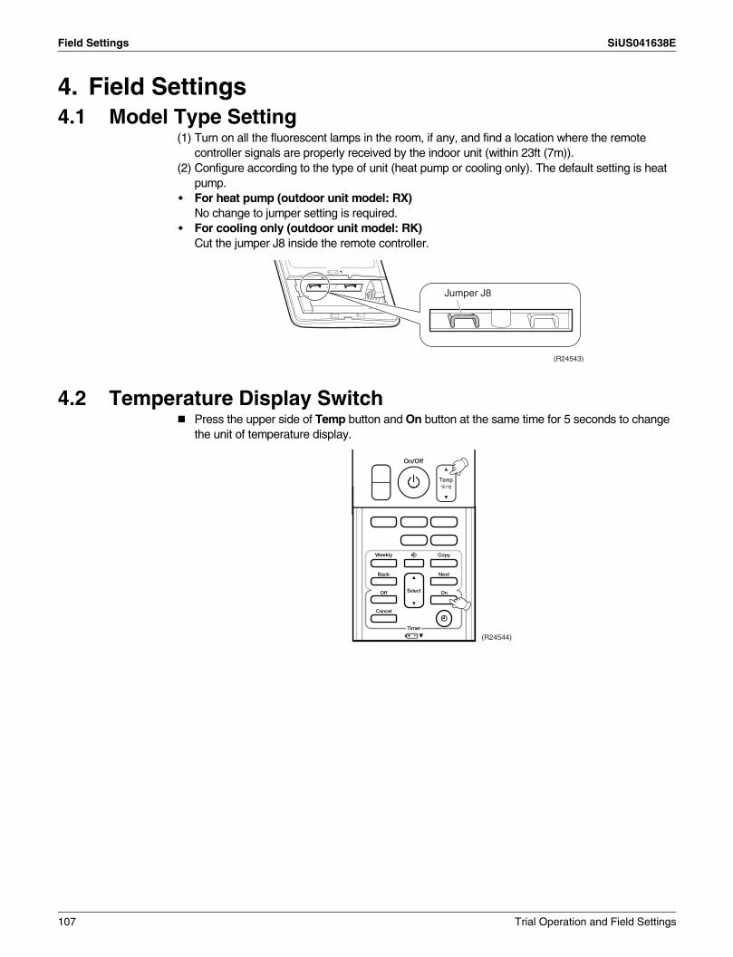
Field Settings SiUS041638E
4. Field Settings4.1 Model Type Setting
(1) Turn on all the fluorescent lamps in the room, if any, and find a location where the remote controller signals are properly received by the indoor unit (within 23ft (7m)).
(2) Configure according to the type of unit (heat pump or cooling only). The default setting is heat pump.For heat pump (outdoor unit model: RX)No change to jumper setting is required.For cooling only (outdoor unit model: RK)Cut the jumper J8 inside the remote controller.
4.2 Temperature Display SwitchPress the upper side of Temp button and On button at the same time for 5 seconds to change the unit of temperature display.
Jumper J8
(R24543)
(R24544)
107 Trial Operation and Field Settings
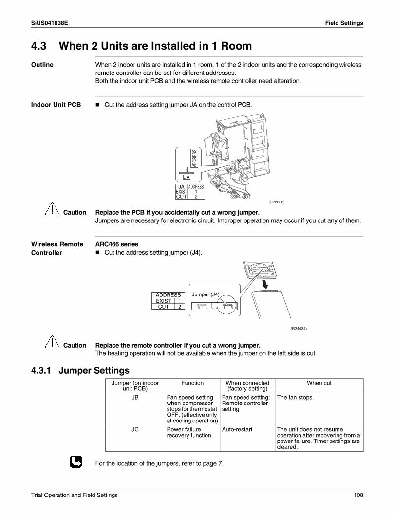
SiUS041638E Field Settings
4.3 When 2 Units are Installed in 1 Room
Outline When 2 indoor units are installed in 1 room, 1 of the 2 indoor units and the corresponding wireless remote controller can be set for different addresses.Both the indoor unit PCB and the wireless remote controller need alteration.
Indoor Unit PCB Cut the address setting jumper JA on the control PCB.
Caution Replace the PCB if you accidentally cut a wrong jumper.Jumpers are necessary for electronic circuit. Improper operation may occur if you cut any of them.
Wireless Remote Controller
ARC466 seriesCut the address setting jumper (J4).
Caution Replace the remote controller if you cut a wrong jumper. The heating operation will not be available when the jumper on the left side is cut.
4.3.1 Jumper Settings
For the location of the jumpers, refer to page 7.
ADDR
ESS
JA
JAEXISTCUT
ADDRESS12
(R22632)
(R24634)
ADDRESSEXIST 1CUT 2
Jumper (J4)
Jumper (on indoor unit PCB)
Function When connected (factory setting)
When cut
JB Fan speed setting when compressor stops for thermostat OFF. (effective only at cooling operation)
Fan speed setting; Remote controller setting
The fan stops.
JC Power failure recovery function
Auto-restart The unit does not resume operation after recovering from a power failure. Timer settings are cleared.
Trial Operation and Field Settings 108

Field Settings SiUS041638E
4.4 Facility Setting Switch (cooling at low outdoor temperature)
Outline This function is designed for facilities such as equipment or computer rooms. It is never to be used in a residence or office where people occupy the space.
Details (1) Turning on SW5-3 on the PCB will extend the operation range to –10°C (14°F).Installing an air direction adjustment grille (sold separately) will further extend the operation range to –20°C (–4°F). In these cases, the unit will stop operating if the outdoor temperature falls below –20°C (–4°F), restarting once the temperature rises above this level.
(2) Only for cooling modelsIf the unit is to be operated in outdoor temperatures down to –30°C (–22°F), turn on SW6-2 on the PCB, in addition to the settings in step (1) above. If the outdoor temperature falls below –30°C (–22°F) the unit will stop operating and will only restart once the temperature rises above –30°C (–22°F).
PCB
HEATCO
OL
4321 21 EDCBA
43
ON
OFF21
SW5
Turn on switch 3.
Screw
(R24546)
Remove the switch cover
PCB
HEATCO
OL
4321 21 EDCBA
ON
OFF21
SW6
Turn on switch 2.
(R24547)
109 Trial Operation and Field Settings
SiUS041638E Field Settings
Caution If the outdoor unit is installed where the outdoor heat exchanger of the unit is exposed to direct wind, provide a windbreak wall.Intermittent noises may be produced by the indoor unit due to the outdoor fan turning on and off when using facility settings.Do not place humidifiers or other items which might raise the humidity in rooms where facility settings are being used.A humidifier might cause dew jumping from the indoor unit outlet vent.Activating the facility setting sets the indoor fan tap to the highest position. Notify the user about this.When the outdoor temperature is below –20°C (–4°F) and if SW6-2 in step 2) below is turned on, for the purpose of protecting the compressor, it may take up to 3 hours for operation to begin while the system warms up.
Trial Operation and Field Settings 110

Silicone Grease on Power Transistor/Diode Bridge SiUS041638E
5. Silicone Grease on Power Transistor/Diode BridgeOutline Apply the specified silicone grease to the heat radiation part of a power transistor/diode bridge when
you replace an outdoor unit PCB. The silicone grease encourages the heat radiation of a power transistor/diode bridge.
Details 1. Wipe off the old silicone grease completely.2. Apply the silicone grease evenly. See the illustrations below for examples of application.3. Tighten the screws of the power transistor/diode bridge.4. Make sure that the heat radiation parts are firmly contacted to the radiation fin.
Note: Smoke emission may be caused by bad heat radiation when the silicone grease is not appropriately applied.
OK: Evenly applied
NG: Not evenly applied
NG: Foreign matter is stuck.
(R22541)
Power transistor (or diode bridge)
Silicone grease
Radiation fin
PCB
(R21866)
Foreign matter (R21867)
111 Trial Operation and Field Settings

SiUS041638E
Appendix 112
Part 8Appendix
1. Piping Diagrams......................................................................................1131.1 Indoor unit ................................................................................................ 1131.2 Outdoor Unit ............................................................................................. 114
2. Wiring Diagrams......................................................................................1152.1 Indoor Unit................................................................................................ 1152.2 Outdoor Unit ............................................................................................. 116
3. Operation Limit........................................................................................117

Piping Diagrams SiUS041638E
1. Piping Diagrams1.1 Indoor unit
FTX30/36NVJU
DISTRIBUTOR
M
HEADER
COOLINGHEATING
INDOOR UNIT
5/16 CuT
HEAT EXCHANGER
THERMISTOR ON HEAT EXCH.CROSS FLOW FAN
FAN MOTOR
FIELD PIPING
1/4 CuT
FIELD PIPING
5/8 CuT
REFRIGERANT FLOW
1/2 CuT
4D107870
113 Appendix
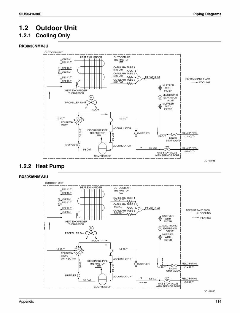
SiUS041638E Piping Diagrams
1.2 Outdoor Unit1.2.1 Cooling Only
RK30/36NMVJU
1.2.2 Heat Pump
RX30/36NMVJU
9/32 CuT
9/32 CuT
9/32 CuT5/32 CuT
9/32 CuT
1/2
CuT
5/32 CuT 1/4 CuT1/4 CuT9/32 CuT
9/32 CuT 5/32 CuT COOLING
M
1/2 CuT
1/2 CuT1/2 CuT
ACCUMULATOR
MUFFLER
3/8
CuT
1/4 CuT
5/8
CuT
MUFFLER ACCUMULATOR5/8 CuT
3/8 CuT
COMPRESSOR
OUTDOOR UNIT
HEAT EXCHANGER
HEAT EXCHANGER THERMISTOR
PROPELLER FAN
OUTDOOR AIR THERMISTOR
CAPILLARY TUBE 1
CAPILLARY TUBE 2
CAPILLARY TUBE 3 REFRIGERANT FLOW
MUFFLER WITH
FILTER
MUFFLER WITH
FILTER
ELECTRONIC EXPANSION
VALVE
FIELD PIPING
(1/4 CuT)
FIELD PIPING
(5/8 CuT)
LIQUID STOP VALVE
GAS STOP VALVE WITH SERVICE PORT
FOUR WAY VALVE
DISCHARGE PIPE THERMISTOR
3D107986
9/32 CuT
9/32 CuT
9/32 CuT5/32 CuT
9/32 CuT
1/2
CuT
5/32 CuT 1/4 CuT1/4 CuT9/32 CuT
9/32 CuT 5/32 CuT
M
1/2 CuT
1/2 CuT1/2 CuT
ACCUMULATOR
MUFFLER
3/8
CuT
1/4 CuT
5/8
CuT
MUFFLER ACCUMULATOR5/8 CuT
3/8 CuT
COMPRESSOR
OUTDOOR UNIT
HEAT EXCHANGER
HEAT EXCHANGER THERMISTOR
PROPELLER FAN
OUTDOOR AIR THERMISTOR
CAPILLARY TUBE 1
CAPILLARY TUBE 2
CAPILLARY TUBE 3
MUFFLER WITH
FILTER
MUFFLER WITH
FILTER
ELECTRONIC EXPANSION
VALVE
COOLING
HEATING
REFRIGERANT FLOW
FIELD PIPING
(1/4 CuT)
FIELD PIPING
(5/8 CuT)
LIQUID STOP VALVE
GAS STOP VALVE WITH SERVICE PORT
FOUR WAY VALVE ON: HEATING
DISCHARGE PIPE THERMISTOR
3D107985
Appendix 114
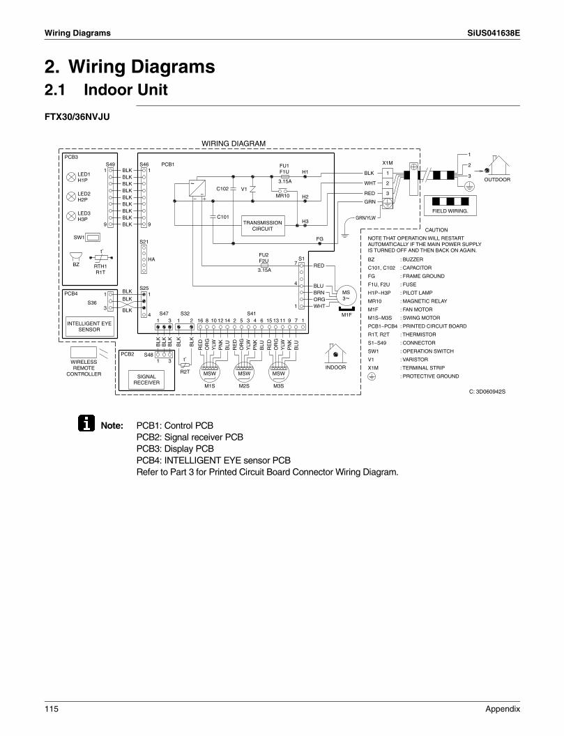
Wiring Diagrams SiUS041638E
2. Wiring Diagrams2.1 Indoor Unit
FTX30/36NVJU
Note: PCB1: Control PCBPCB2: Signal receiver PCBPCB3: Display PCBPCB4: INTELLIGENT EYE sensor PCBRefer to Part 3 for Printed Circuit Board Connector Wiring Diagram.
1
X1MPCB1
PCB3
S46S49 2H11 1 1 3
~ 3.15A OUTDOOR2
C102 V13- H2MR10
BLK
WHT
RED
GRN
C101H3
99
BLKBLKBLKBLKBLKBLKBLKBLKBLK
CAUTION
FGSW1S21
t˚S1HA
7BZ3.15A
4S25
1 1PCB4
S361
RED
BLUBRNORGWHT3
S41S47 S32
BLK
BLK
BLK4 M1F
5 1612 1542 2 13 91 11 731 16 10 38 14
BLK
BLK
BLK
BLK
BLK
PN
K
PN
K
PN
K
BLU
BLU
BLU
OR
G
OR
G
OR
G
RE
D
RE
D
RE
D
YLW
YLW
YLW
S48PCB2t˚1 3
INDOORR2T MSW MSWMSW
M1S M3SM2S
WIRING DIAGRAM
LED1 H1P
LED2 H2P
LED3 H3P
RTH1 R1T
INTELLIGENT EYE SENSOR
WIRELESS REMOTE
CONTROLLER SIGNAL RECEIVER
FU1 F1U
TRANSMISSION CIRCUIT
FU2 F2U
MS 3~
GRN/YLWFIELD WIRING.
NOTE THAT OPERATION WILL RESTART AUTOMATICALLY IF THE MAIN POWER SUPPLY IS TURNED OFF AND THEN BACK ON AGAIN.
BZ
C101, C102
FG
F1U, F2U
H1P~H3P
MR10
M1F
M1S~M3S
PCB1~PCB4
R1T, R2T
S1~S49
SW1
V1
X1M
: BUZZER
: CAPACITOR
: FRAME GROUND
: FUSE
: PILOT LAMP
: MAGNETIC RELAY
: FAN MOTOR
: SWING MOTOR
: PRINTED CIRCUIT BOARD
: THERMISTOR
: CONNECTOR
: OPERATION SWITCH
: VARISTOR
: TERMINAL STRIP
: PROTECTIVE GROUND
C: 3D060942S
115 Appendix

SiUS041638E Wiring Diagrams
2.2 Outdoor Unit
RK(X)30/36NMVJU
Note: PCB1: Main PCBPCB2: Service monitor PCBRefer to Part 3 for Printed Circuit Board Connector Wiring Diagram.
GRN/YLW M1CPCB2 SW6SW4SW2X1M LED21BRN SW1 SW353 SW54AL1L1
BLU M1FL2 S2L2S501Z1C S5021 11 51Z2C MS
BLU
RED
YLW
X11AY1SG
RY
BRN
GRN
PPL
RED
BLU
BLK
RED
ORG
BRN
GRN
GRY
BLK
GRNZ5C YLW
YLW
WHT
BLK
WHT
Z3CPCB1 E2E1 CK15111 1
BRN
ORG
RED
RED
BLU
BLU
YLW
YLW
YLW
WHTS201 S202
SA1X2M
7 13 4 3 21 UVW11S70S80V222 HL1 MRM20
33 MRM10 MR4ZFV3HN1
MRM11 W UDB1 VDC+~ + ++V401 PSRED 1Z4C
C110
S ~ - -DC-
IPM1WHT9
S90 S4015 4811 S20
BLK
BLK
RED
BLK
ORG
BLU
BLK
BLK
YLW
WHT
t˚ t˚t˚MR2T R1TR3T Q1L
Y1E
(DIS
CHAR
GE)
(CO
NDEN
SER)
(OUT
DOO
R)
INDOOR OUTDOOR
POWER SUPPLY
WIRING DIAGRAM
TO INDOOR UNIT
FIELD WIRING
SHEET METAL
ROOM A
FU3 30A
FOR LINE TESTING
SK
Y
BLU
FU1 3.15A
FU2 3.15A
IN CASE OF HEAT PUMP TYPE
MS 3~
C110DB1FU1, FU2, FU3IPM1L1, L2LEDAM1CM1F
: CAPACITOR: DIODE BRIDGE: FUSE: INTELLIGENT POWER MODULE: LIVE: PILOT LAMP: COMPRESSOR MOTOR: FAN MOTOR
SHEET METALSW5, SW6V2, V3, V401X1M, X2MY1EY1SZ1C~Z5CZF
: TERMINAL BLOCK FIXED PLATE: FUNCTION SW: VARISTOR: TERMINAL BLOCK: ELECTRONIC EXPANSION VALVE COIL: REVERSING SOLENOID VALVE COIL: FERRITE CORE: NOISE FILTER
NOTE: GROUND: SW1~SW4 AND LED1~LED5 DO NOT WORK.
MR4, MRM10, MRM11, MRM20PCB1, 2PSQ1LR1T~R3TS, S2~S502, X11ASA1
: MAGNETIC RELAY: PRINTED CIRCUIT BOARD: SWITCHING POWER SUPPLY: OVERLOAD PROTECTOR: THERMISTOR: CONNECTOR: SURGE ARRESTER
3D106580
Appendix 116
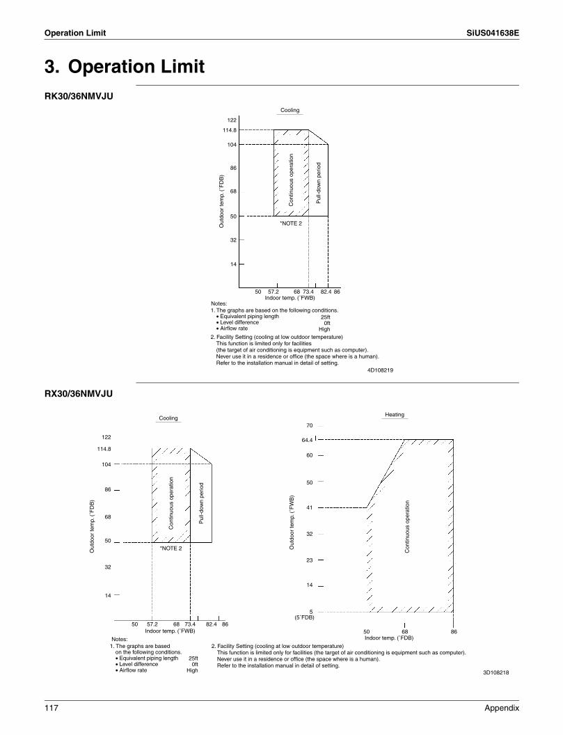
Operation Limit SiUS041638E
3. Operation LimitRK30/36NMVJU
RX30/36NMVJU
Cooling
114.8
104
Out
door
tem
p. (
˚FD
B)
Pul
l-dow
n pe
riod
Con
tinuo
us o
pera
tion
14
32
50*NOTE 2
68
86
122
57.2 68 73.4 82.4 8650Indoor temp. (˚FWB)
25ft0ft
High
4D108219
Notes: 1. The graphs are based on the following conditions.
• Equivalent piping length• Level difference• Airflow rate
2. Facility Setting (cooling at low outdoor temperature)This function is limited only for facilities (the target of air conditioning is equipment such as computer).Never use it in a residence or office (the space where is a human).Refer to the installation manual in detail of setting.
HeatingCooling
Out
door
tem
p. (
˚FD
B)
Pul
l-dow
n pe
riod
Con
tinuo
us o
pera
tion
Out
door
tem
p. (
˚FW
B)
Con
tinuo
us o
pera
tion
50 57.2 68 73.4 82.4 86Indoor temp. (˚FWB) 50 68 86
Notes: Indoor temp. (˚FDB)
(5˚FDB)
1. The graphs are based on the following conditions.• Equivalent piping length• Level difference• Airflow rate
25ft0ft
High
2. Facility Setting (cooling at low outdoor temperature)This function is limited only for facilities (the target of air conditioning is equipment such as computer).Never use it in a residence or office (the space where is a human).Refer to the installation manual in detail of setting.
114.8
104
14
5
14
23
32
41
50
60
70
64.4
32
50
68
86
122
3D108218
*NOTE 2
117 Appendix
Revision History
Month / Year Version Revised contents
03 / 2017 SiUS041638E First edition

Warning Daikin products are manufactured for export to numerous countries throughout the world. Prior to purchase, please confirm with your local authorized importer, distributor and/or retailer whether this product conforms to the applicable standards, and is suitable for use, in the region where the product will be used. This statement does not purport to exclude, restrict or modify the application of any local legislation.
Ask a qualified installer or contractor to install this product. Do not try to install the product yourself. Improper installation can result in water or refrigerant leakage, electrical shock, fire or explosion.
Use only those parts and accessories supplied or specified by Daikin. Ask a qualified installer or contractor to install those parts and accessories. Use of unauthorized parts and accessories or improper installation of parts and accessories can result in water or refrigerant leakage, electrical shock, fire or explosion.
Read the user's manual carefully before using this product. The user's manual provides important safety instructions and warnings. Be sure to follow these instructions and warnings.
If you have any inquiries, please contact your local importer, distributor and/or retailer.
Cautions on product corrosion1. Air conditioners should not be installed in areas where corrosive gases, such as acid gas or alkaline gas, are produced.2. If the outdoor unit is to be installed close to the sea shore, direct exposure to the sea breeze should be avoided. If you need to install
the outdoor unit close to the sea shore, contact your local distributor.
Dealer
Specifications, designs and other content appearing in this brochure are current as of March 2017 but subject to change without notice.
SiUS041638EPrinted in U.S.A. 03/2017 B AK
All rights reservedc