service manual number 14 gear housing standard rotation
TRANSCRIPT

3B
GEAR HOUSING STANDARD ROTATIONSERVICE MANUAL NUMBER 14
90-818177--3 APRIL 2001 Page 3B-1
STERNDRIVE UNITSection 3B - Gear Housing Standard Rotation
Table of Contents
Standard Rotation Gear Housing Specifications 3B-2. . . . . . . . . . . . . . . . . . . . . .
Torque Specifications 3B-2. . . . . . . . . . . . . Shimming Specifications 3B-2. . . . . . . . . . . Lubricants / Sealers / Adhesives 3B-2. . . . Special Tools 3B-3. . . . . . . . . . . . . . . . . . . . . Special Tools (continued) 3B-4. . . . . . . . . .
Standard Rotation Gear Housing Exploded Parts View 3B-6. . . . . . . . . . . . . . . .
Drive Shaft Components 3B-6. . . . . . . . . . . Propeller Shaft Components 3B-8. . . . . . .
Special Information 3B-10. . . . . . . . . . . . . . . . . . Shift Spool Assembly 3B-10. . . . . . . . . . . . . Forward Gear Bearing Bore 3B-11. . . . . . . .
Pre-Disassembly Inspection 3B-12. . . . . . . . . . Propeller 3B-12. . . . . . . . . . . . . . . . . . . . . . . . Propeller Shaft 3B-12. . . . . . . . . . . . . . . . . . .
Drive Shaft Housing/Gear Housing 3B-13. . . . Separation 3B-13. . . . . . . . . . . . . . . . . . . . . . .
Gear Housing and Component Disassembly 3B-15. . . . . . . . . . . . . . . . . . . . . . .
Water Pump Subassembly 3B-15. . . . . . . . . Oil Seal Carrier Subassembly 3B-18. . . . . . Bearing Carrier Subassembly 3B-21. . . . . . Drive Shaft Assembly 3B-34. . . . . . . . . . . . . Propeller Shaft Assembly and Forward Gear Bearing Cup 3B-37. . . . . . . . Forward Gear Assembly 3B-41. . . . . . . . . . .
Shift Spool Assembly 3B-44. . . . . . . . . . . . . Propeller Shaft Assembly 3B-45. . . . . . . . . . Shift Shaft Assembly 3B-47. . . . . . . . . . . . . . Pinion Bearing 3B-50. . . . . . . . . . . . . . . . . . .
Gear Housing Reassembly 3B-51. . . . . . . . . . . Gear Housing Inspection 3B-51. . . . . . . . . . Pinion Bearing 3B-51. . . . . . . . . . . . . . . . . . . Forward Gear Bearing Cup 3B-52. . . . . . . . Shift Shaft Assembly 3B-53. . . . . . . . . . . . . . Propeller Shaft Assembly 3B-55. . . . . . . . . . Drive Shaft and Pinion Gear 3B-57. . . . . . . Drive Shaft - Bearing Preload Tool 3B-60. . Pinion Gear Location 3B-61. . . . . . . . . . . . . . Bearing Carrier Assembly 3B-62. . . . . . . . . . Forward Gear Backlash 3B-65. . . . . . . . . . . Reverse Gear Backlash 3B-67. . . . . . . . . . . Forward and/or Reverse Gear Backlash Adjustment 3B-69. . . . . . . . . . . . . Drive Shaft - Bearing Preload Tool 3B-69. .
Bearing Carrier Assembly 3B-70. . . . . . . . . . . . Final Installation 3B-70. . . . . . . . . . . . . . . . . .
Oil Seal Carrier Assembly 3B-74. . . . . . . . . . . . Installation 3B-74. . . . . . . . . . . . . . . . . . . . . . .
Water Pump Assembly 3B-75. . . . . . . . . . . . . . . Installation 3B-75. . . . . . . . . . . . . . . . . . . . . . .
Joining Drive Shaft Housing/Gear Housing 3B-78. . . . . . . . . . . . . . . . . . . . . . . . . . .

GEAR HOUSING STANDARD ROTATION SERVICE MANUAL NUMBER 14
Page 3B-2 90-818177--3 APRIL 2001
Standard Rotation Gear Housing Specifications
Torque Specifications
TorqueDescription
lb-in. lb-ft Nm
Water Pump Body Screws 60 6.8
Pinion Gear Nut 70 95
Gear Housing-To-Drive Shaft Housing Screws 28 38
Gear Housing-To-Drive Shaft Housing Nuts 35 47
Trim Tab Screw Or Anodic Plate 23 31
Shift Shaft Bushing Screws 60 6.8
Drive Shaft Retainer 100 136
Bear Carrier Retainer 210 285
Oil Fill/Drain Screw 40 4.5
Propeller Nut 1 55 75
1: Amount specified is MINIMUM.
Shimming Specifications
Gear LocationDescription
inches millimeters
Pinion Gear Height .025 0.64
Forward Gear Backlash .017-.028 0.43-0.71
Reverse Gear Backlash .028-.060 0.71-1.32
Lubricants / Sealers / Adhesives
Description Part Number
Quicksilver 2-4-C Marine Lubricant With Teflon 92-825407A12
3M Brand Adhesive 92-86166Q1
Quicksilver Needle Bearing Assembly Lubricant 92-825265A1
Quicksilver Perfect Seal 92-34227-1
Permatex Ultra Blue Silicone Sealant Obtain Locally
Quicksilver Special Lubricant 101 92-13872A1
Loctite 271 92-809820
Quicksilver High Performance Gear Lube 92-850743A1
GEAR HOUSING STANDARD ROTATIONSERVICE MANUAL NUMBER 14
90-818177--3 APRIL 2001 Page 3B-3
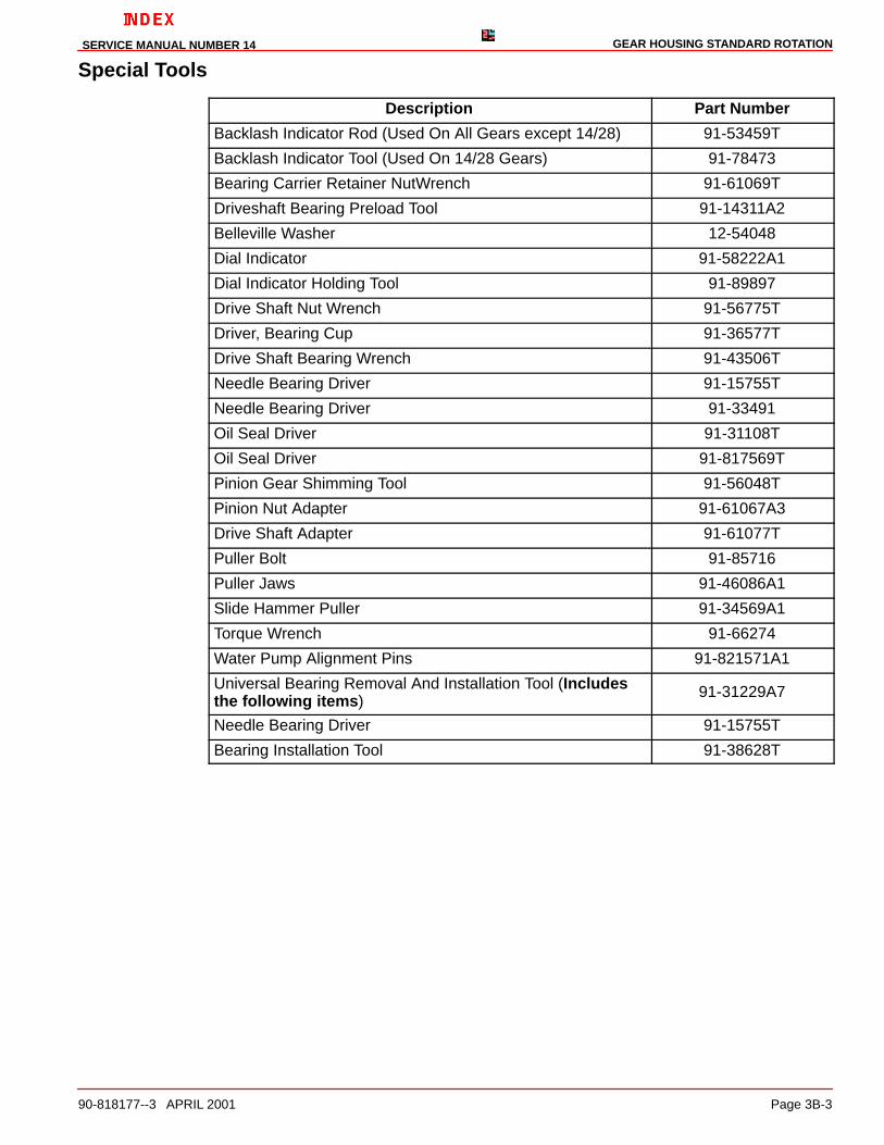
Special Tools
Description Part Number
Backlash Indicator Rod (Used On All Gears except 14/28) 91-53459T
Backlash Indicator Tool (Used On 14/28 Gears) 91-78473
Bearing Carrier Retainer NutWrench 91-61069T
Driveshaft Bearing Preload Tool 91-14311A2
Belleville Washer 12-54048
Dial Indicator 91-58222A1
Dial Indicator Holding Tool 91-89897
Drive Shaft Nut Wrench 91-56775T
Driver, Bearing Cup 91-36577T
Drive Shaft Bearing Wrench 91-43506T
Needle Bearing Driver 91-15755T
Needle Bearing Driver 91-33491
Oil Seal Driver 91-31108T
Oil Seal Driver 91-817569T
Pinion Gear Shimming Tool 91-56048T
Pinion Nut Adapter 91-61067A3
Drive Shaft Adapter 91-61077T
Puller Bolt 91-85716
Puller Jaws 91-46086A1
Slide Hammer Puller 91-34569A1
Torque Wrench 91-66274
Water Pump Alignment Pins 91-821571A1
Universal Bearing Removal And Installation Tool (Includesthe following items)
91-31229A7
Needle Bearing Driver 91-15755T
Bearing Installation Tool 91-38628T

GEAR HOUSING STANDARD ROTATION SERVICE MANUAL NUMBER 14
Page 3B-4 90-818177--3 APRIL 2001
Special Tools (continued)
Description Part Number
Collar 91-30366T-1
Needle Bearing Driver 91-32336
Driver Head 91-36569T
Prop Shaft Needle Bearing Driver 91-37311
Driveshaft Needle Bearing Driver 91-37312T
Needle Bearing Driver 91-52393T
Needle Bearing Driver Rod 91-37323
Nut 11-24156
Pilot Washer 91-36571T
Needle Bearing Pilot Washer 91-37324T
Pilot Washer 91-37350T
Puller Plate 91-29310
Gear Puller 91-36379
Puller Head 91-32325T
Bearing Installation Tool 91-38628T
Puller Head 91-52394
Puller Shaft 91-31229
Roller Bearing Removal and Installation Tool 91-37292
Washer 12-34961
*The 91-14311A2 Bearing Preload Tool is also used on Mercury and Mariner V-6 gearcases. Check your inventory before buying.
NOTE: Water Pump Face Seal Tool is not available separately, 26-816575A2 is a kit partnumber which includes the tool and the face seal.

GEAR HOUSING STANDARD ROTATIONSERVICE MANUAL NUMBER 14
90-818177--3 APRIL 2001 Page 3B-5
THIS PAGE IS INTENTIONALLY BLANK

GEAR HOUSING STANDARD ROTATION SERVICE MANUAL NUMBER 14
Page 3B-6 90-818177--3 APRIL 2001
Standard Rotation Gear Housing Exploded Parts View
Drive Shaft Components
74242
A
D
A
A
A(ID)
C
A
B
A
E
C.
B
F
75664
A
C
��
��
��
�
a
b
c
a
a
d
��
��
��
��
��
��
��
��
��
��
��
�
�
�
��
����
��
�
��
��
��
��
�
�
�
�
�
�
�
��
�
����
GEAR HOUSING STANDARD ROTATIONSERVICE MANUAL NUMBER 14
90-818177--3 APRIL 2001 Page 3B-7
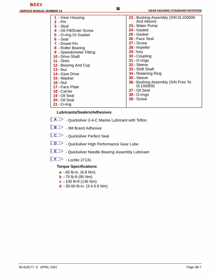
1 - Gear Housing2 - Pin3 - Stud4 - Oil Fill/Drain Screw5 - O-ring Or Gasket6 - Seal7 - Dowel Pin8 - Roller Bearing9 - Speedometer Fitting
10 - Drive Shaft11 - Shim12 - Bearing And Cup13 - Nut14 - Gear Drive15 - Washer16 - Nut17 - Face Plate18 - Carrier19 - Oil Seal20 - Oil Seal21 - O-ring
22 - Bushing Assembly (S/N 0L100009And Above)
23 - Water Pump24 - Gasket25 - Gasket26 - Face Seal27 - Screw28 - Impeller29 - Key30 - Coupling31 - O-rings32 - Sleeve33 - Shift Shaft34 - Retaining Ring35 - Sleeve36 - Bushing Assembly (S/N Prior To
0L100009)37 - Oil Seal38 - O-rings39 - Screw
Lubricants/Sealers/Adhesives
A - Quicksilver 2-4-C Marine Lubricant with Teflon
B - 3M Brand Adhesive
C - Quicksilver Perfect Seal
D - Quicksilver High Performance Gear Lube
E - Quicksilver Needle Bearing Assembly Lubricant
F - Loctite 27131
Torque Specificationsa - 60 lb-in. (6.8 Nm)b - 70 lb-ft (95 Nm)c - 100 lb-ft (136 Nm)d - 30-50 lb-in. (3.4-5.6 Nm)

GEAR HOUSING STANDARD ROTATION SERVICE MANUAL NUMBER 14
Page 3B-8 90-818177--3 APRIL 2001
Propeller Shaft Components
F(OD)
A(ID)
C
C
CE
D
F
75691
��
a
b
d
e
��
�
��
��
��
�
�
�
�
�
��
�
��
�
��
��
�
��
�
��
��
����
��
��
���
��
�
��
��
��

GEAR HOUSING STANDARD ROTATIONSERVICE MANUAL NUMBER 14
90-818177--3 APRIL 2001 Page 3B-9
1 - Gear Housing2 - Shift Crank3 - Shift Spool Assembly4 - Shim, Bearing Outer Race5 - Bearing And Cup6 - Forward Gear7 - Roller Bearing8 - Sliding Clutch9 - Cross Pin
10 - Spring11 - Propeller Shaft12 - Reverse Gear13 - Thrust Washer14 - Thrust Hub15 - Ball Bearing16 - O-ring17 - Roller Bearing18 - Bearing Carrier Assembly
19 - Anode20 - Screw21 - Star Washer22 - Oil Seal (Inside)23 - Oil Seal (Outside)24 - Tab Washer25 - Retainer26 - Thrust Hub27 - Continuity Washer28 - Spline Washer29 - Tab Washer30 - Locknut - Propeller31 - Anodic Trim Tab (Anodic Plate - Some
Models)32 - Screw33 - Star Washer34 - Screw35 - Nut
Lubricants/Sealers/Adhesives
A - Quicksilver 2-4-C Marine Lubricant with Teflon
B - Loctite 27131
C - Quicksilver High Performance Gear Lube
D - Quicksilver Perfect Seal
E - Permatex Ultra Blue Silicone Sealant
F - Quicksilver Special Lubricant 101
Torque Specificationsa - 28 lb-ft (38 Nm)b - 35 lb-ft (47.5 Nm)c - 23 lb-ft (31 Nm)d - 210 lb-ft (285 Nm)e - 80 lb-in. (9 Nm)

GEAR HOUSING STANDARD ROTATION SERVICE MANUAL NUMBER 14
Page 3B-10 90-818177--3 APRIL 2001
Special Information
CAUTIONAvoid damage to sterndrive unit. Drive unit damage will occur if Later Style partsare intermixed with Earlier Style parts
Shift Spool AssemblyThe later style shift spool assembly has a larger gap than the earlier style. This later styleshift spool beginning with serial number 0K041000 is sold as a whole assembly and can beused when replacing the earlier style (Prior to S/N 0K041000). The end play for the spoolwill remain the same as the earlier models (.002-.010 in. .051-.254 mm).
7521974877
cc
ab
a - Earlier Style Shift Spool Assembly (Prior To S/N 0K041000)b - Later Style Shift Spool Assembly (S/N 0K041000 And Above)c - Measure End Play Here At Gap

GEAR HOUSING STANDARD ROTATIONSERVICE MANUAL NUMBER 14
90-818177--3 APRIL 2001 Page 3B-11
Forward Gear Bearing BoreThe later style forward gear bearing bore is smaller (3.2635 to 3.2650 in.) than the earlierstyle (3.4985 to 3.5000 in.) This slightly smaller bearing bore for the forward gear bearingadapter is approximately 1/4 in. (6.3 mm) smaller.
75241
3.4985to3.5000
Earlier Style Forward Gear Bore (Prior to S/N OF680000)
75248
3.2635to3.2650
Later Style Forward Gear Bore (S/N OF680000 and Above)
The later style bearing cup is thinner and has a smaller diameter than the earlier style.
75256b
a
a - Earlier Style Gear Bearing Cup 3.500 in. Diameter (Prior To S/N OF680000)b - Later Style Gear Bearing Cup 3.265 in. Diameter (S/N OF680000 and Above)

GEAR HOUSING STANDARD ROTATION SERVICE MANUAL NUMBER 14
Page 3B-12 90-818177--3 APRIL 2001
Pre-Disassembly Inspection
Propeller
REMOVAL
1. If not already accomplished, remove the propeller and its mounting components.
Propeller Shaft
INSPECTION
1. Inspect the propeller shaft for side to side movement, as follows:
a. Position the dial indicator on the propeller shaft.
b. Push the propeller shaft to one side and zero the dial indicator.
c. Move the propeller shaft to the opposite side while observing the dial indicator.Ashaft deflection of more than .003 in. (0.08 mm) indicates a worn propeller shaftbearing.
2. Check for a bent propeller shaft as follows:
a. Rotate the drive shaft in gear while observing the dial indicator. If the deflection ismore than .007 in. (0.178 mm), a bent propeller shaft is indicated.
22086
GEAR HOUSING STANDARD ROTATIONSERVICE MANUAL NUMBER 14
90-818177--3 APRIL 2001 Page 3B-13
Drive Shaft Housing/Gear Housing
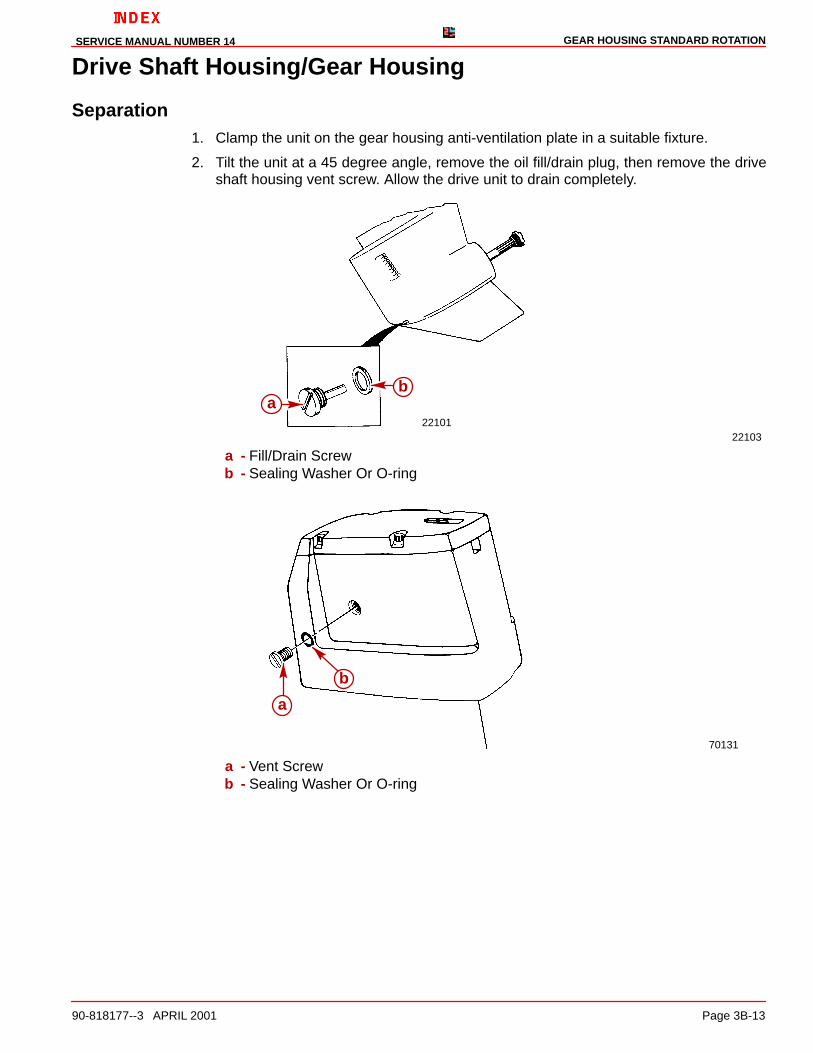
Separation1. Clamp the unit on the gear housing anti-ventilation plate in a suitable fixture.
2. Tilt the unit at a 45 degree angle, remove the oil fill/drain plug, then remove the driveshaft housing vent screw. Allow the drive unit to drain completely.
2210122103
ab
a - Fill/Drain Screwb - Sealing Washer Or O-ring
70131
a
b
a - Vent Screwb - Sealing Washer Or O-ring

GEAR HOUSING STANDARD ROTATION SERVICE MANUAL NUMBER 14
Page 3B-14 90-818177--3 APRIL 2001
3. Mark the trim tab position (if equipped) with a piece of tape on the gear housing and re-move the trim tab or anodic plate, if equipped.
70116
a
b
a - Trim Tabb - Extension With 1/2 in. Socket
4. Remove the bolts, nuts and washers from the port and starboard sides of the unit.
5. Remove the aft screw (in the trim tab well of the gear housing).
6. Remove the nut from the forward end of the unit.
70117
a
cb
a - Nuts, Bolts And Washersb - Nutc - Screw
7. Lift the drive shaft housing straight off of the gear case and set aside.

GEAR HOUSING STANDARD ROTATIONSERVICE MANUAL NUMBER 14
90-818177--3 APRIL 2001 Page 3B-15
Gear Housing and Component Disassembly
Water Pump Subassembly
REMOVAL
1. Remove the water seal, water tube coupling assembly and the water pump screws.
70486
ac
b
a - Water Tube Assemblyb - Water Pump Screwsc - Water Seal
2. Carefully slide the water pump straight up off of the drive shaft. It may be necessary togently pry up on its mounting flanges with a couple of screwdrivers.
70487
a
b b
a - Water Pump Bodyb - Screwdrivers
GEAR HOUSING STANDARD ROTATION SERVICE MANUAL NUMBER 14
Page 3B-16 90-818177--3 APRIL 2001
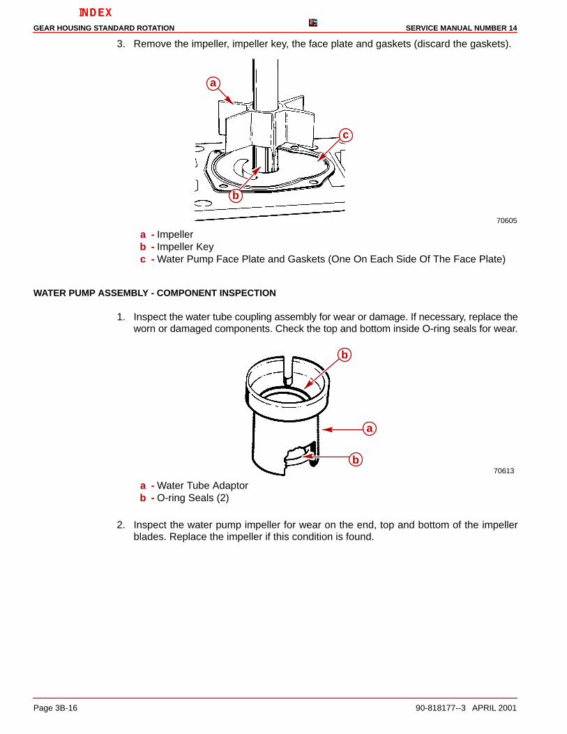
3. Remove the impeller, impeller key, the face plate and gaskets (discard the gaskets).
70605
c
a
b
a - Impellerb - Impeller Keyc - Water Pump Face Plate and Gaskets (One On Each Side Of The Face Plate)
WATER PUMP ASSEMBLY - COMPONENT INSPECTION
1. Inspect the water tube coupling assembly for wear or damage. If necessary, replace theworn or damaged components. Check the top and bottom inside O-ring seals for wear.
70613
b
a
b
a - Water Tube Adaptorb - O-ring Seals (2)
2. Inspect the water pump impeller for wear on the end, top and bottom of the impellerblades. Replace the impeller if this condition is found.
GEAR HOUSING STANDARD ROTATIONSERVICE MANUAL NUMBER 14
90-818177--3 APRIL 2001 Page 3B-17
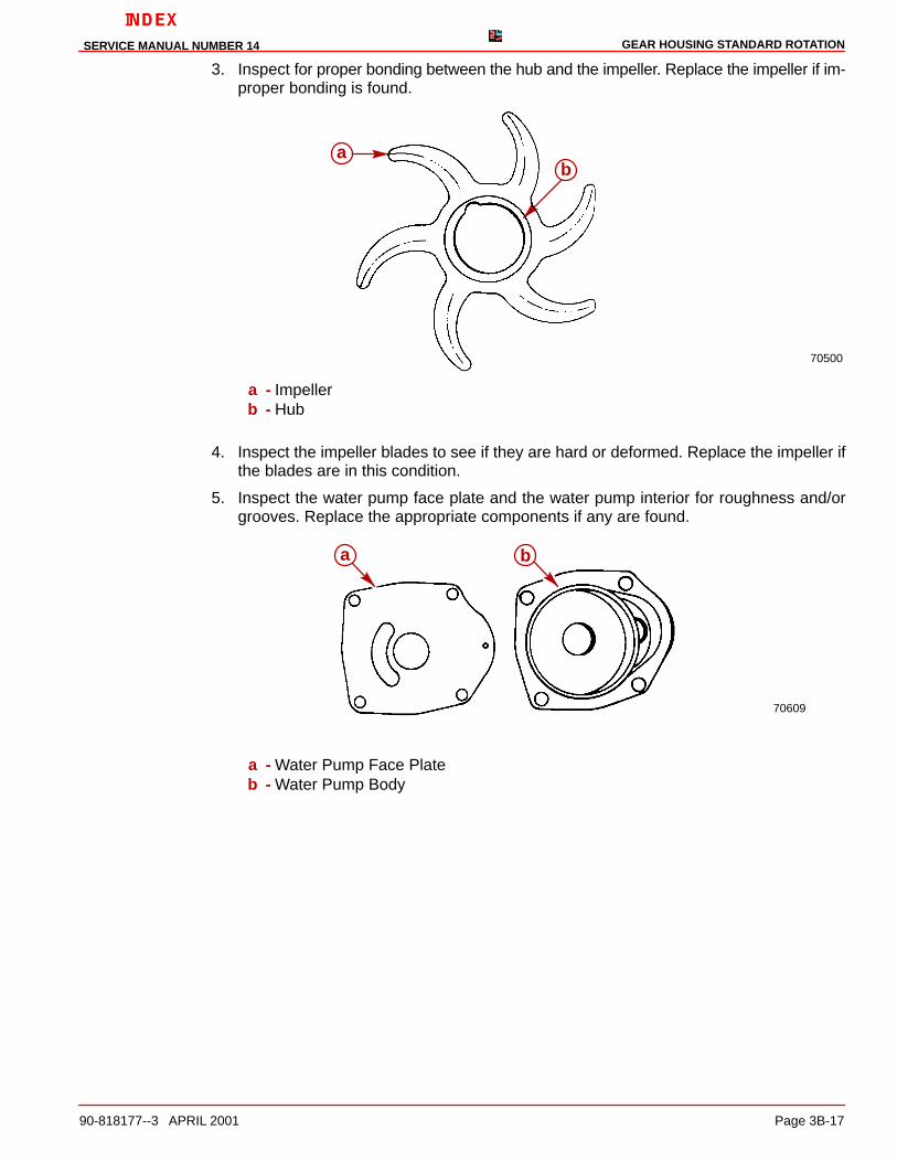
3. Inspect for proper bonding between the hub and the impeller. Replace the impeller if im-proper bonding is found.
70500
ba
a - Impellerb - Hub
4. Inspect the impeller blades to see if they are hard or deformed. Replace the impeller ifthe blades are in this condition.
5. Inspect the water pump face plate and the water pump interior for roughness and/orgrooves. Replace the appropriate components if any are found.
70609
a b
a - Water Pump Face Plateb - Water Pump Body
GEAR HOUSING STANDARD ROTATION SERVICE MANUAL NUMBER 14
Page 3B-18 90-818177--3 APRIL 2001
Oil Seal Carrier Subassembly
REMOVAL
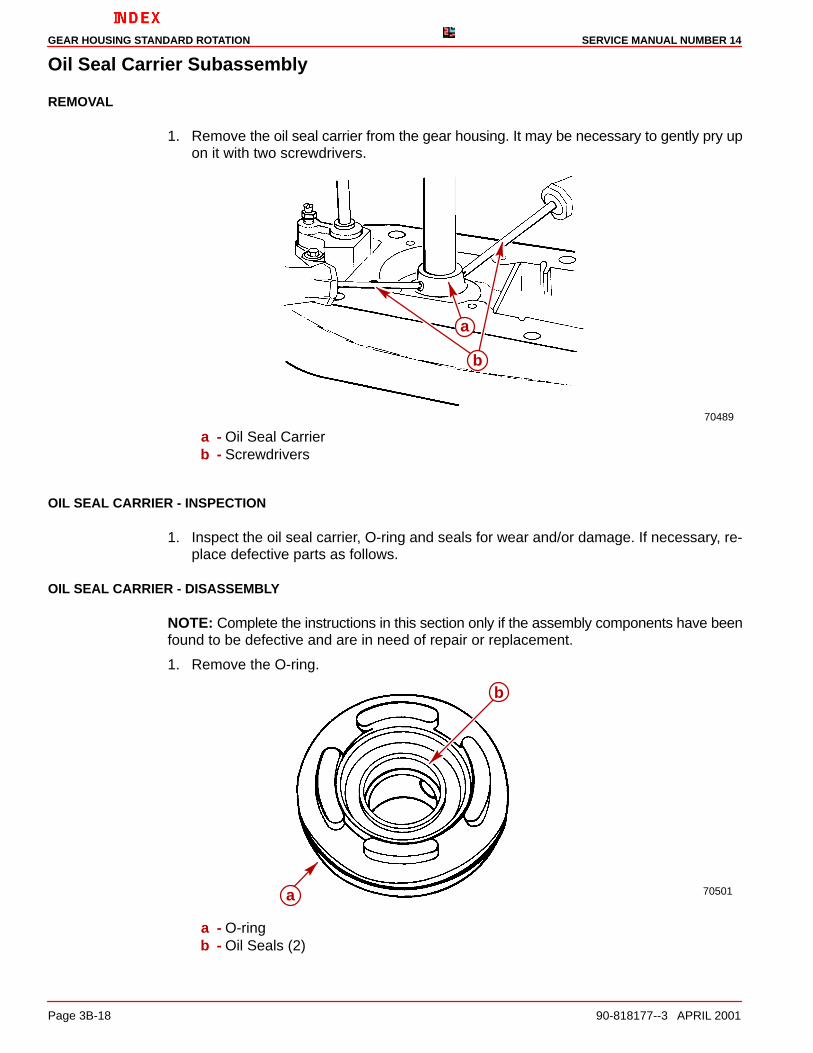
1. Remove the oil seal carrier from the gear housing. It may be necessary to gently pry upon it with two screwdrivers.
70489
a
b
a - Oil Seal Carrierb - Screwdrivers
OIL SEAL CARRIER - INSPECTION
1. Inspect the oil seal carrier, O-ring and seals for wear and/or damage. If necessary, re-place defective parts as follows.
OIL SEAL CARRIER - DISASSEMBLY
NOTE: Complete the instructions in this section only if the assembly components have beenfound to be defective and are in need of repair or replacement.
1. Remove the O-ring.
70501a
b
a - O-ringb - Oil Seals (2)

GEAR HOUSING STANDARD ROTATIONSERVICE MANUAL NUMBER 14
90-818177--3 APRIL 2001 Page 3B-19
2. Remove the oil seals.
70610
c b
a
a - Oil Seal Carrierb - Oil Sealsc - Screwdriver
OIL SEAL CARRIER - REASSEMBLY
The oil seal carrier may be a brown color (aluminum) material or a black color (glass fillednylon) material. This black glass filled seal carrier will supersede the aluminum version. Thenew seal carrier can be identified by looking at the base. Where the old plastic carrier hadonly two support feet the new one will have four support feet. Also the seals in the old alumi-num oil seal carrier are metal case and will require Loctite 27131 applied to the outside diam-eter prior to installation.
NOTE: Complete the instructions in this section only if the assembly components have beendisassembled and repaired or replaced.
7050171435
A. Earlier Style B. Later Style. . . . . . . . . .
NOTE: The earlier style oil seal carrier utilizes a large diameter and a small diameter oil seal.The later style uses the same oil seals as the drive shaft housing.
1. Apply Quicksilver Perfect Seal sparingly to the oil seal bore prior to installing the oil sealinto the oil seal carrier.
2. Assemble the small oil seal (with the lips of the oil seal facing away from the driver shoul-der) onto the long end of the oil seal driver.

GEAR HOUSING STANDARD ROTATION SERVICE MANUAL NUMBER 14
Page 3B-20 90-818177--3 APRIL 2001
3. Press on the oil seal driver until the driver bottoms against the carrier. Do not press toohard as it could damage the oil seal carrier while driving the oil seal.
70611
d
ca
b
a - Oil Sealb - Oil Seal Driver (91-817569) (Use Long End)c - Oil Seal Carrierd - Press
4. Apply Quicksilver Perfect Seal sparingly to the seal bore prior to installing oil seal intothe oil seal carrier.
5. Assemble the large oil seal (with the lips of the oil seal facing the driver shoulder) ontothe short end of the oil seal driver.
6. Press on the oil seal driver until the driver touches the carrier. Do not press too hard asit could damage the oil seal carrier while driving the oil seal.
70612
a
b
d
c
a - Oil Sealb - Oil Seal Driver (91-817569) (Use Short End)c - Oil Seal Carrierd - Press

GEAR HOUSING STANDARD ROTATIONSERVICE MANUAL NUMBER 14
90-818177--3 APRIL 2001 Page 3B-21
7. Install the O-ring onto the oil seal carrier.
70501a
Typicala - O-ring
Bearing Carrier Subassembly
REMOVAL
1. If equipped, remove anode from bearing carrier.
71958
a
b
a - Anodeb - Screws

GEAR HOUSING STANDARD ROTATION SERVICE MANUAL NUMBER 14
Page 3B-22 90-818177--3 APRIL 2001
2. Straighten the tab on the tab washer.
70490
a
a - Tab on Tab Washer
3. Remove the bearing carrier retainer following Step “a” or “b” as necessary:
CAUTIONDO NOT drill into the gear housing retainer threads when using the following proce-dure for removing the retainer.
a. Remove the bearing carrier retainer using the Bearing Carrier Retainer Wrench(91-61069).
70491
a
a - Bearing Carrier Retainer Wrench

GEAR HOUSING STANDARD ROTATIONSERVICE MANUAL NUMBER 14
90-818177--3 APRIL 2001 Page 3B-23
b. If the retainer is corroded in place, drill 4 holes in the retainer and fracture the retainerwith a chisel. Pry the remaining segments out.
23356
a
a - Drilled Holes
FOR EARLIER STYLE UNITS:
CAUTIONDO NOT pull on the bearing carrier outer ring, as damage to the carrier will result.
4. Pull the bearing carrier from the gear housing by the inner bosses located on the centerarea by the oil seals.
NOTE: If the bearing carrier is seized in the gear housing, it may be necessary to use heatto loosen the carrier.
70934
a
b
Earlier Style Unitsa - Puller Jaws (91-46086 A1)b - Puller Bolt (91-85716)
FOR LATER STYLE UNITS:
5. Pull the bearing carrier from the gear housing by pulling on the outer ring of the bearingcarrier.

GEAR HOUSING STANDARD ROTATION SERVICE MANUAL NUMBER 14
Page 3B-24 90-818177--3 APRIL 2001
NOTE: If the bearing carrier is seized in the gear housing, it may be necessary to use heatto loosen the carrier.
70492
b
a
Later Style Unitsa - Puller Jaws (91-46086 A1)b - Puller Bolt (91-85716)
NOTE: Puller jaws are oriented differently on the Earlier Style and the Later Style Units.
BEARING CARRIER ASSEMBLY - INSPECTION
1. Clean the assembly with a suitable solvent and dry the parts thoroughly using com-pressed air.
NOTE: If any of the following items are found to be defective complete the appropriate in-struction(s) in “Bearing Carrier Assembly.”
2. Inspect the bearing carrier for signs of excessive corrosion especially in the area wherethe bearing carrier touches the gear housing. If excessive corrosion is evident, replacethe carrier.
50314
a
b
a - Bearing Carrierb - Mating Surfaces

GEAR HOUSING STANDARD ROTATIONSERVICE MANUAL NUMBER 14
90-818177--3 APRIL 2001 Page 3B-25
3. The condition of the bearing surface on the propeller shaft in the area that the needlebearing (in the bearing carrier) rides is an indication of the condition of the needle bear-ing in the bearing carrier. Replace the bearing if the surface of the shaft is pitted,grooved, scored, worn unevenly, discolored from overheating or has embedded metalparticles.
23355
a
a - Propeller Shaft Bearing Contact Area
4. Inspect the reverse gear for pitted, chipped, broken teeth, hairline fractures and exces-sive or uneven wear. Replace the gear if any defects are found.
5. Inspect the clutch jaws of the gear for damage. Surfaces must not be chipped or roundedoff. Replace the gear if any are found. Also inspect later model reverse gear and thrustspacer combination for excessive thrust spacer wear.
23355
a
b
Earlier Model Reverse Geara - Reverse Gear Teethb - Clutch Jaws
74150
a
b
Later Model Reverse Gear and Thrust Spacera - Thrust Washerb - Reverse Gear

GEAR HOUSING STANDARD ROTATION SERVICE MANUAL NUMBER 14
Page 3B-26 90-818177--3 APRIL 2001
6. Inspect the reverse gear bearing for excessive movement or roughness by rotating gear.Replace the bearing if either of these conditions exists.
7. Inspect the bearing carrier retainer for cracks and/or broken or corroded threads.Replace it if any are found.
8. Remove the O-ring from the bearing carrier assembly.
23354
a
b
a - Bearing Carrierb - O-ring
a. Inspect the O-ring for damage and or deterioration. Replace as necessary.
BEARING CARRIER ASSEMBLY - COMPONENT DISASSEMBLY AND INSPECTION
NOTE: Complete the instructions in this section only if the assembly components have beenfound to be defective and are in need of repair or replacement.
CAUTIONClamp onto the reinforcing rib of the bearing carrier ONLY, or damage to the carriermay result.
1. Remove thrust spacer from later model reverse gear (if applicable).
2. Place the bearing carrier in a vise, clamping on the reinforcing rib.

GEAR HOUSING STANDARD ROTATIONSERVICE MANUAL NUMBER 14
90-818177--3 APRIL 2001 Page 3B-27
3. Remove the reverse gear, thrust ring and bearing as an assembly, using a slide hammerpuller.
23352
ab
c
d ef
a - Bearing Carrier Reinforcing Ribb - Bearing Carrierc - Slide Hammer Puller (91-34569 A1)d - Reverse Geare - Thrust Hubf - Bearing Located In The Carrier
4. Clean all components thoroughly with a suitable solvent and inspect them for damageand/or excessive wear. Replace any parts that are found to be defective.
IMPORTANT: The bearing MUST BE replaced if removed from gear.
5. Place the universal puller plate between the thrust washer and bearing as shown andpress on the plate until it bottoms.
23351
a
c
b
a - Universal Puller Plate (91-37241)b - Thrust Washerc - Bearing
GEAR HOUSING STANDARD ROTATION SERVICE MANUAL NUMBER 14
Page 3B-28 90-818177--3 APRIL 2001
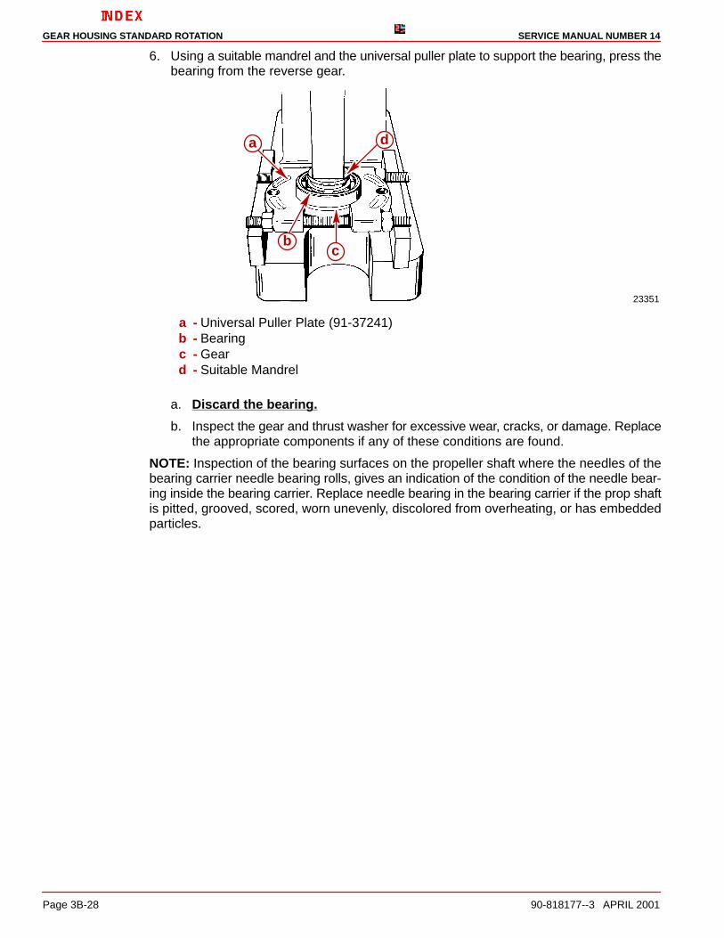
6. Using a suitable mandrel and the universal puller plate to support the bearing, press thebearing from the reverse gear.
23351
a
bc
d
a - Universal Puller Plate (91-37241)b - Bearingc - Geard - Suitable Mandrel
a. Discard the bearing.
b. Inspect the gear and thrust washer for excessive wear, cracks, or damage. Replacethe appropriate components if any of these conditions are found.
NOTE: Inspection of the bearing surfaces on the propeller shaft where the needles of thebearing carrier needle bearing rolls, gives an indication of the condition of the needle bear-ing inside the bearing carrier. Replace needle bearing in the bearing carrier if the prop shaftis pitted, grooved, scored, worn unevenly, discolored from overheating, or has embeddedparticles.

GEAR HOUSING STANDARD ROTATIONSERVICE MANUAL NUMBER 14
90-818177--3 APRIL 2001 Page 3B-29
7. Perform Step “a” or “b” as necessary.
a. If Replacing The Needle Bearing And Seals: Remove the needle bearing andseals with the tools as shown. Discard the needle bearing and both seals.
23140
a
b
c
d
a - Bearing Driver Rod (91-37323)b - Driver Head (91-36569)c - Needle Bearingd - Oil Seals
b. If Replacing The Seal Only: Remove the oil seals with a suitable pry bar, beingcareful not to damage the bore of the bearing carrier. Discard both of the seals.
23140
ba
a - Oil Sealsb - Pry Bar

GEAR HOUSING STANDARD ROTATION SERVICE MANUAL NUMBER 14
Page 3B-30 90-818177--3 APRIL 2001
BEARING CARRIER - REASSEMBLY
NOTE: Complete the instructions in this section only if the assembly components have beendisassembled and repaired or replaced.
1. Clean all of the components with a suitable solvent and dry the parts thoroughly usingcompressed air. Be careful not to spin the bearing.
2. Lubricate the bore that the needle bearing is pressed into with 2-4-C Marine Lubricantwith Teflon. Make sure that none of the lubricant gets onto the seal bore. If it does, makesure that it is thoroughly cleaned off after the needle bearing is installed in the nextstep.
3. Assemble the needle bearing (with the numbered end of the bearing towards the drivershoulder), onto the driver.
4. Press the needle bearing into the bearing carrier until the driver bottoms out on the bear-ing carrier. Ensure that the numbered side of the needle bearing faces the seal end (aftend) of the carrier.
50315
c
ba
a - Needle Bearing Driver (91-15755)b - Needle Bearingc - Bearing Carrier
5. Thoroughly clean the bore in which the first seal is to be pressed.
6. Assemble the first seal (with the lips of the seal facing away from the driver shoulder)onto the long end of the oil seal driver.

GEAR HOUSING STANDARD ROTATIONSERVICE MANUAL NUMBER 14
90-818177--3 APRIL 2001 Page 3B-31
7. Press on the oil seal driver until the driver rests on the aft face of the bearing carrier.
50315
c
ab
a - Oil Seal Driver (91-31108)b - Oil Sealc - Bearing Driver
8. Apply a thin film of Loctite 271 to the bore in which the second seal is to be pressed.
9. Assemble the second seal (with the lips of the seal facing the driver shoulder) onto theshort end of the driver.
10. Press the oil seal with the driver until the driver rests on the bearing carrier.
50315
a
b
c
a - Driver (Short End)b - Oil Seal (Lips Toward Driver Shoulder)c - Bearing Driver
11. Wipe up all of the excess Loctite. Do not allow any of the excess Loctite to spread toother parts of the assembly.

GEAR HOUSING STANDARD ROTATION SERVICE MANUAL NUMBER 14
Page 3B-32 90-818177--3 APRIL 2001
12. Install the thrust washer and new ball bearing onto the reverse gear. Press on the innerrace of the ball bearing using the pilot washer until the bearing rests on the gear.
23346
a
b
c
d
a - Pilot Washer (91-36571)b - Ball Bearingc - Thrust Hubd - Reverse Gear
13. Lightly lubricate the bore that the bearing is pressed into with 2-4-C Marine Lubricantwith Teflon.
14. Press the bearing carrier onto the reverse gear and bearing until the bearing rests onthe bearing carrier, using the pilot washer to press against the carrier.
23349
a
b
c
a - Pilot Washer (91-36571)b - Bearing Carrierc - Reverse Gear and Bearing Assembly

GEAR HOUSING STANDARD ROTATIONSERVICE MANUAL NUMBER 14
90-818177--3 APRIL 2001 Page 3B-33
15. Install the O-ring onto the bearing carrier.
23354
b
a
a - O-ringb - Bearing Carrier
16. If equipped with thrust spacer, install it into gear as shown.
71910
a
b
a - Thrust Spacerb - Reverse Gear
GEAR HOUSING STANDARD ROTATION SERVICE MANUAL NUMBER 14
Page 3B-34 90-818177--3 APRIL 2001
Drive Shaft Assembly
REMOVAL
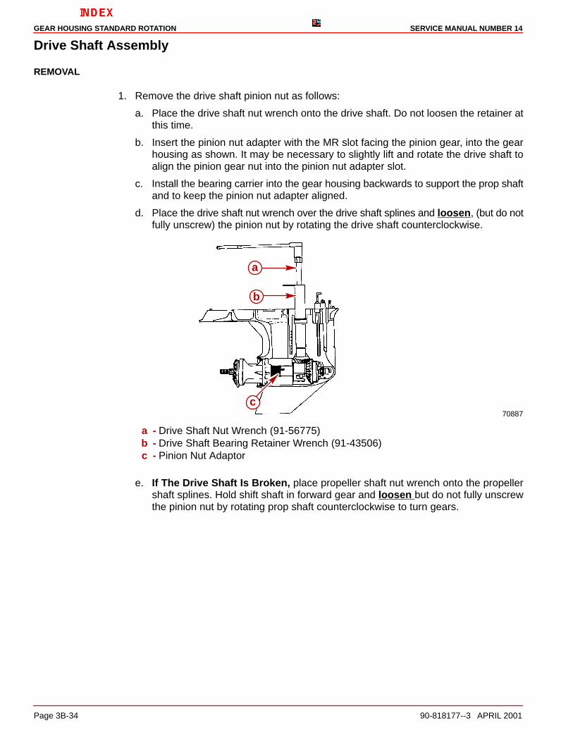
1. Remove the drive shaft pinion nut as follows:
a. Place the drive shaft nut wrench onto the drive shaft. Do not loosen the retainer atthis time.
b. Insert the pinion nut adapter with the MR slot facing the pinion gear, into the gearhousing as shown. It may be necessary to slightly lift and rotate the drive shaft toalign the pinion gear nut into the pinion nut adapter slot.
c. Install the bearing carrier into the gear housing backwards to support the prop shaftand to keep the pinion nut adapter aligned.
d. Place the drive shaft nut wrench over the drive shaft splines and loosen, (but do notfully unscrew) the pinion nut by rotating the drive shaft counterclockwise.
70887
a
b
c
a - Drive Shaft Nut Wrench (91-56775)b - Drive Shaft Bearing Retainer Wrench (91-43506)c - Pinion Nut Adaptor
e. If The Drive Shaft Is Broken, place propeller shaft nut wrench onto the propellershaft splines. Hold shift shaft in forward gear and loosen but do not fully unscrewthe pinion nut by rotating prop shaft counterclockwise to turn gears.

GEAR HOUSING STANDARD ROTATIONSERVICE MANUAL NUMBER 14
90-818177--3 APRIL 2001 Page 3B-35
NOTE: The propeller shaft nut wrench is included with the pinion nut adapter kit.
70607
c
b
a
a - Pinion Nut Adaptor (91-61067 A3)b - Propeller Shaft Nut Wrench (91-61077)c - Shift Shaft (Turn Clockwise)
f. Completely unscrew the drive shaft bearing retainer.
g. Completely unscrew the pinion nut by rotating the drive shaft (or the propeller shaft)in a counterclockwise direction.
h. Remove all tools.
IMPORTANT: The pinion bearing rollers are free to fall out of the pinion bearing oncethe drive shaft is removed. Be careful not to lose the (18) rollers.
2. Remove the drive shaft and all components by pulling the drive shaft straight out of thegear housing as shown.
70608
b
a
a - Drive Shaftb - Drive Shaft Retainer, Bearing Cup, Bearing and Shims
3. Retrieve the pinion gear, the washer and the nut from the inside of the gear housing.

GEAR HOUSING STANDARD ROTATION SERVICE MANUAL NUMBER 14
Page 3B-36 90-818177--3 APRIL 2001
DRIVE SHAFT ASSEMBLY - INSPECTION
1. Clean all parts with a suitable solvent and dry the parts thoroughly using compressedair. Be careful not to spin the bearings.
2. The condition of the drive shaft bearing cup is an indication of the condition of the ta-pered roller bearing on the drive shaft. Replace the bearing and bearing cup if the cupis pitted, grooved, scored, worn unevenly, discolored from overheating, or has em-bedded particles.
3. Inspect the bearing surface on the drive shaft where the needles of the lower pinionbearing roll. Replace the drive shaft if it is pitted, grooved, scored, worn unevenly, discol-ored from overheating, or has embedded particles.
4. Inspect the splines at both ends of the drive shaft for a worn or twisted condition. Replacethe drive shaft if either condition exists.
5. Inspect the gear for pitting, chipped or broken teeth, hairline fractures and excessive oruneven wear. Replace the pinion gear and the forward gear if any defects are found.
DRIVE SHAFT - DISASSEMBLY
NOTE: Complete the instructions in this section only if the assembly components have beenfound to be defective and are in need of repair or replacement.
CAUTIONEnsure that the universal puller plate does not contact with the sides of the driveshaft.
1. Press the tapered roller bearing from the drive shaft using the universal puller plate tosupport the inner race of the bearing while removing it.
70699
c
b
a
a - Universal Puller Plate (91-37241)b - Tapered Roller Bearingc - Drive Shaft
DRIVE SHAFT - REASSEMBLY
NOTE: Complete the instructions in this section only if the assembly components have beendisassembled and repaired or replaced.

GEAR HOUSING STANDARD ROTATIONSERVICE MANUAL NUMBER 14
90-818177--3 APRIL 2001 Page 3B-37
CAUTIONEnsure that the universal puller plate does not make contact with the sides of thedrive shaft.
1. Assemble a new tapered roller bearing on the drive shaft with the large O.D. of the bear-ing facing the pinion gear end of the drive shaft.
2. Press the tapered roller bearing onto the drive shaft using the universal puller plate anda suitable mandrel (an old tapered roller bearing inner race).
77707
bc
a
a - Universal Puller Plate (91-37241)b - Tapered Roller Bearingc - Suitable Mandrel
Propeller Shaft Assembly and Forward Gear Bearing Cup
REMOVAL
1. Tilt the propeller shaft to the port side of the gear housing and remove the shaft by pullingit up and out.
23348
a
bc
a - Propeller Shaft Assemblyb - Shift Spoolc - Shift Crank

GEAR HOUSING STANDARD ROTATION SERVICE MANUAL NUMBER 14
Page 3B-38 90-818177--3 APRIL 2001
2. Remove the forward gear bearing cup and shims. Measure and make note of the shimthickness and discard (do not reuse) the shims.
74008
a
b
d
c
e
f
g
h
a - Puller Shaft (91-31229)b - Nut (11-24156)c - Guide Plate (91-816243)d - Washer (91-34961)e - Puller Head (From Slide Hammer Puller 91-34589A1)f - Jaws (From Slide Hammer Puller 91-34589A1)g - Bearing Adaptorh - Shims

GEAR HOUSING STANDARD ROTATIONSERVICE MANUAL NUMBER 14
90-818177--3 APRIL 2001 Page 3B-39
PROPELLER SHAFT DISASSEMBLY
NOTE: When accomplishing the next step, all of the parts are free to come apart. Workclosely over a work bench to ensure that the parts are not dropped or damaged and to avoidpersonal injury.
1. Remove the spring around the clutch being careful not to over-stretch it during removal.If the spring does not coil back to its normal position once it has been removed, it mustbe replaced.
50885d c
b
a
a - Springb - Shift Spool Assemblyc - Reverse Gear Assemblyd - Sliding Clutch
2. Remove the cross pin that goes through the clutch.
50885
a
a - Cross Pin
3. Remove the remainder of the components.

GEAR HOUSING STANDARD ROTATION SERVICE MANUAL NUMBER 14
Page 3B-40 90-818177--3 APRIL 2001
PROPELLER SHAFT INSPECTION
1. Clean all the parts with a suitable solvent and dry the parts thoroughly using compressedair, being careful not to spin bearings.
2. Inspect the sliding clutch jaws for damage. Jaws must not be chipped or rounded off.Replace the clutch if they are.
3. Inspect the bearing surfaces on the propeller shaft where the needles of the bearing car-rier needle bearing and the needles of the forward gear needle bearing roll. Replace thepropeller shaft if it is pitted, grooved, scored, worn unevenly, discolored from overheat-ing, or has embedded particles.
23355
ba
c
a - Bearing Carrier Needle Bearing Contact Areab - Forward Gear Needle Bearing Contact Areac - Splines
4. Inspect the propeller shaft splines at both ends for a broken, worn, or twisted condition.Replace the propeller shaft if any of these conditions exists.
5. Inspect the surface of the propeller shaft where the bearing carrier seal lips contact theshaft. If the oil seals have made grooves, the propeller shaft must be replaced.
6. Inspect the propeller shaft for a bent condition. Use either one of the following methods.
a. Method 1 - V-Blocks and Dial Indicator
(1.)Position the propeller shaft bearing surfaces on V-blocks.
(2.)Adjust the height of V-blocks to level the propeller shaft.
(3.)Position the dial indicator tip just forward of the propeller shaft splines.
b. Method 2 - Lathe and Dial Indicator
(1.)Mount the propeller shaft between the centers of a lathe or other appropriate de-vice.
(2.)Position the dial indicator tip just forward of the propeller shaft splines.
23355
b
aa
a - Propeller Shaft Centersb - Check Movement With Dial Indicator (91-58222 A1)
7. Rotate the propeller shaft and observe the dial indicator movement, If the indicator inthe dial moves more than .007 in. (0.178 mm), replace the propeller shaft.

GEAR HOUSING STANDARD ROTATIONSERVICE MANUAL NUMBER 14
90-818177--3 APRIL 2001 Page 3B-41
Forward Gear Assembly
INSPECTION
1. Clean the forward gear assembly and the forward gear bearing cup, thoroughly with asuitable solvent and dry thoroughly with compressed air. Be careful not to spin the bear-ings.
2. Inspect the gear for pitting, chipped or broken teeth, hairline fractures and excessive oruneven wear. Replace the forward gear and the pinion gear if any defects are found.
3. Inspect the clutch jaws of the gear for damage. The surfaces must not be chipped orrounded off. Replace both the forward and pinion gear if any of these conditions exist.
23351
a
b
a - Forward Gear Teethb - Clutch Jaws
4. Inspect the needle bearings on the inside of the forward gear and the bearing surfaceon the propeller shaft. If either the needle bearing or the bearing surface of the propellershaft is pitted, grooved, scored, worn unevenly, discolored from overheating, or has em-bedded particles, replace the propeller shaft and remove and replace the needle bear-ing in the forward gear as outlined in the next section.
23355
a
a - Forward Gear Needle Bearing Contact Area
5. Inspect the tapered roller bearings on the forward gear and the bearing surface on theforward gear bearing cup. If either the roller bearings or the bearing surface of the for-ward gear bearing cup is pitted, grooved, scored, worn unevenly, discolored from over-heating, or has embedded particles, replace the forward gear bearing cup and removeand replace the tapered roller bearings as outlined in the next section.
GEAR HOUSING STANDARD ROTATION SERVICE MANUAL NUMBER 14
Page 3B-42 90-818177--3 APRIL 2001
FORWARD GEAR DISASSEMBLY
NOTE: Complete the instructions in this section only if the assembly components have beenfound to be defective and are in need of repair or replacement.
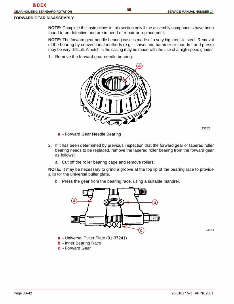
NOTE: The forward gear needle bearing case is made of a very high tensile steel. Removalof the bearing by conventional methods (e.g. - chisel and hammer or mandrel and press)may be very difficult. A notch in the casing may be made with the use of a high speed grinder.
1. Remove the forward gear needle bearing.
23352
a
a - Forward Gear Needle Bearing
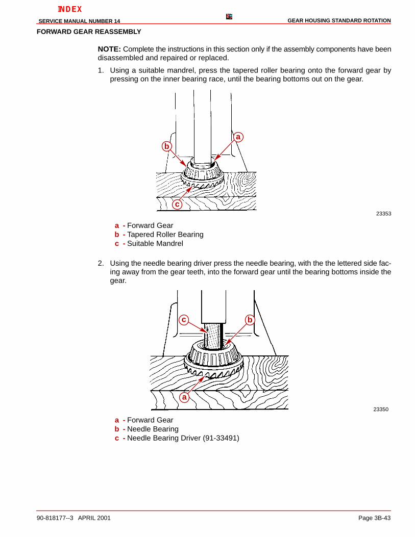
2. If it has been determined by previous inspection that the forward gear or tapered rollerbearing needs to be replaced, remove the tapered roller bearing from the forward gearas follows:
a. Cut off the roller bearing cage and remove rollers.
NOTE: It may be necessary to grind a groove at the top lip of the bearing race to providea lip for the universal puller plate.
b. Press the gear from the bearing race, using a suitable mandrel.
23141
a b
c
a - Universal Puller Plate (91-37241)b - Inner Bearing Racec - Forward Gear
GEAR HOUSING STANDARD ROTATIONSERVICE MANUAL NUMBER 14
90-818177--3 APRIL 2001 Page 3B-43
FORWARD GEAR REASSEMBLY
NOTE: Complete the instructions in this section only if the assembly components have beendisassembled and repaired or replaced.
1. Using a suitable mandrel, press the tapered roller bearing onto the forward gear bypressing on the inner bearing race, until the bearing bottoms out on the gear.
23353
ab
c
a - Forward Gearb - Tapered Roller Bearingc - Suitable Mandrel
2. Using the needle bearing driver press the needle bearing, with the the lettered side fac-ing away from the gear teeth, into the forward gear until the bearing bottoms inside thegear.
23350
a
bc
a - Forward Gearb - Needle Bearingc - Needle Bearing Driver (91-33491)

GEAR HOUSING STANDARD ROTATION SERVICE MANUAL NUMBER 14
Page 3B-44 90-818177--3 APRIL 2001
Shift Spool Assembly
INSPECTION
1. Clean the assembly with a suitable solvent and dry the parts thoroughly using com-pressed air.
2. Inspect the shift spool assembly for damage. Small nicks and burrs may be smoothed.If any parts are damaged or worn beyond repair it will be necessary to replace the com-plete shift spool assembly. Individual parts are not available for the assembly.
3. Inspect the shift spool for wear in the area where the shift crank comes into contact.
23356
a
a - Contact Area
4. Ensure that the spool spins freely. It may be helpful to lightly tap the castle nut end ofthe shift shaft against a firm surface to align the internal parts.
5. Ensure that the spool has 0.002-0.010 (0.051-0.254 mm) end play.
6. To check end play:
a. Push in on the shift spool. Take measurement.
b. Pull out on the shift spool. Take measurement.
c. The difference between the two measurements is the end play.
74877
ab
c
a - Shift Shaftb - Spoolc - Gap
NOTE: The later style shift spool assembly has a larger gap than the earlier style. This laterstyle shift spool beginning with serial number 0K041000 is sold as a whole assembly and

GEAR HOUSING STANDARD ROTATIONSERVICE MANUAL NUMBER 14
90-818177--3 APRIL 2001 Page 3B-45
can be used when replacing the earlier style (Prior to S/N 0K041000). The end play for thespool will remain the same as the earlier models .002-.010 in. (.051-.254 mm).
7521974877
a
c c
b
a - Earlier Style Shift Spool Assembly (Prior To S/N 0k041000)b - Later Style Shift Spool Assembly (S/N 0k041000 And Above)c - Measure End Play Here At Gap
Propeller Shaft Assembly
REASSEMBLY
NOTE: Complete the instructions in this section only if the assembly components have beendisassembled and repaired or replaced.
1. Assemble the sliding clutch on the propeller shaft, being sure to align cross pin holesin the clutch with the slot in the propeller shaft. Make sure that the sliding clutch is placedon the propeller shaft with the grooved end of the clutch facing the propeller end of theshaft.
2. Assemble the forward gear assembly to the propeller shaft.
3. Assemble the shift spool assembly to the propeller shaft being sure to align the crosspin hole of the shift spool shaft with the clutch.
4. Assemble the cross pin through the sliding clutch, through the propeller shaft andthrough the shift spool shaft hole.
5. Assemble the cross pin retaining spring over the propeller end of the propeller shaft andwind it around the clutch over the cross pin hole. Be careful not to distort the spring whileassembling it.

GEAR HOUSING STANDARD ROTATION SERVICE MANUAL NUMBER 14
Page 3B-46 90-818177--3 APRIL 2001
IMPORTANT: Make sure that the spring is wound on so that it does not cross over onitself and that it lies flat against the clutch once it is assembled. If it does not lie flatagainst the clutch, a new spring must be installed.
23350
f
eg
b
d a c
a - Sliding Clutchb - Grooves in Clutchc - Forward Gear Assemblyd - Cross Pine - Propeller Shaftf - Spool and Actuating Shaft Assemblyg - Cross Pin Retaining Spring

GEAR HOUSING STANDARD ROTATIONSERVICE MANUAL NUMBER 14
90-818177--3 APRIL 2001 Page 3B-47
Shift Shaft Assembly
REMOVAL
NOTE: It is possible to remove and service the shift shaft assembly (but not the shift crankinside the gear case) without removing any of the internal components of the gear housing.
1. Remove the shift shaft bushing screws and remove the shift shaft by pulling it straightout of gear housing.
70494
aa
a - Shift Shaft Bushing Screws
2. Remove the shift crank from the inside of the gear housing. Clean it with a suitable sol-vent and dry it thoroughly. Inspect it for wear in the areas that contact the shift spool andinspect the splines and the diameter that goes over the locating pin for damage or exces-sive wear.
23350
b
c d
a
a - Contact Areab - Shift Crankc - Splinesd - Diameter for Locating Pin
GEAR HOUSING STANDARD ROTATION SERVICE MANUAL NUMBER 14
Page 3B-48 90-818177--3 APRIL 2001
DISASSEMBLY AND INSPECTION
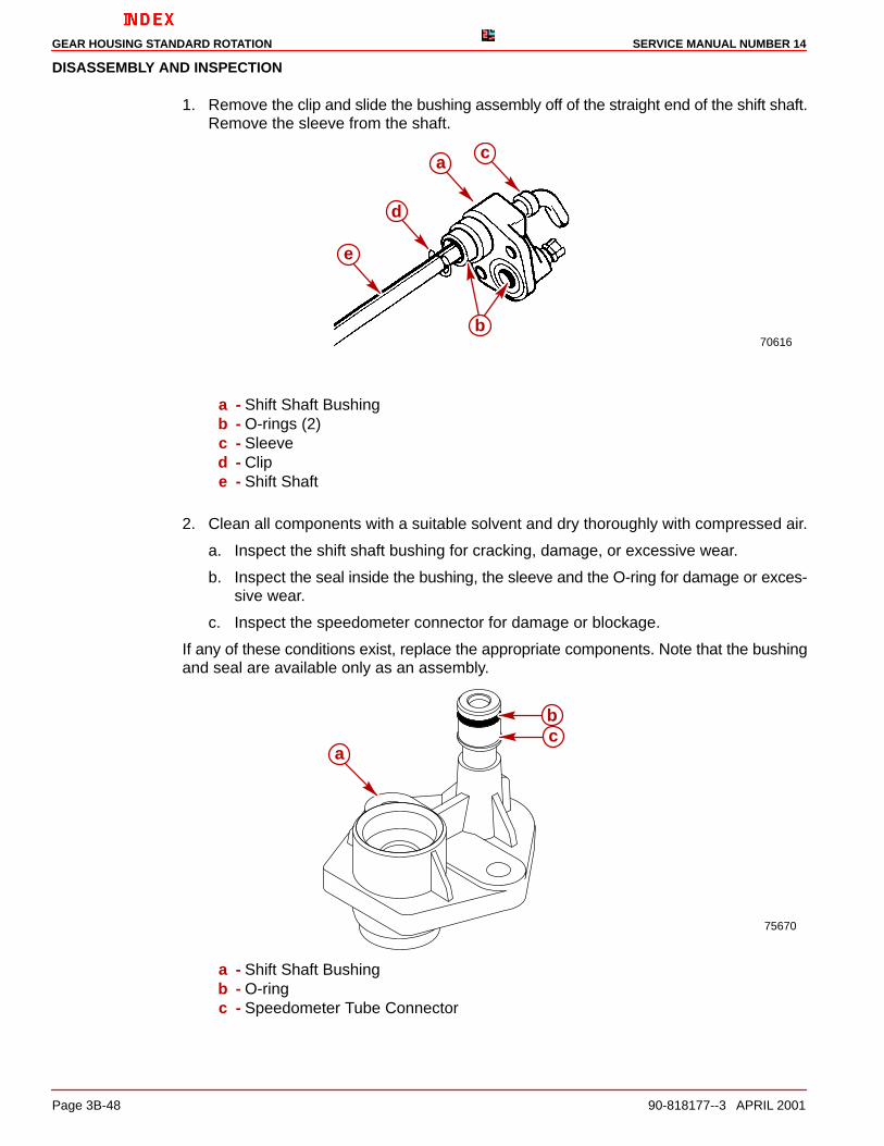
1. Remove the clip and slide the bushing assembly off of the straight end of the shift shaft.Remove the sleeve from the shaft.
70616
c
e
d
a
b
a - Shift Shaft Bushingb - O-rings (2)c - Sleeved - Clipe - Shift Shaft
2. Clean all components with a suitable solvent and dry thoroughly with compressed air.
a. Inspect the shift shaft bushing for cracking, damage, or excessive wear.
b. Inspect the seal inside the bushing, the sleeve and the O-ring for damage or exces-sive wear.
c. Inspect the speedometer connector for damage or blockage.
If any of these conditions exist, replace the appropriate components. Note that the bushingand seal are available only as an assembly.
75670
a
bc
a - Shift Shaft Bushingb - O-ringc - Speedometer Tube Connector

GEAR HOUSING STANDARD ROTATIONSERVICE MANUAL NUMBER 14
90-818177--3 APRIL 2001 Page 3B-49
3. Inspect the shift shaft splines and seal surface for corrosion, bent condition and/or ex-cessive wear. Replace the shift shaft if either if these conditions are found.
70618
b a
a - Seal Surfaceb - Spline
REASSEMBLY
NOTE: Complete the instructions in this section only if the assembly components have beendisassembled and repaired or replaced.
1. Lightly lubricate the seats of the O-ring diameters on the bushing and the lip of the oilseal with Quicksilver 2-4-C Marine Lubricant with Teflon.
2. If the speedometer connector was removed and/or replaced, lightly coat the threads ofthe connector with Quicksilver Perfect Seal. Assemble the speedometer connector tothe bushing and torque the connector to 4.5 lb-in. (0.51 Nm).
3. Assemble all components.
70616
c
e
d
a
b
a - Shift Shaft Bushingb - O-rings (2)c - Sleeved - Clipe - Shift Shaft
NOTE: For reinstalling the shift shaft when none of the other components of the gear hous-ing were disassembled see the “Shift Shaft Assembly,” “Installation.”

GEAR HOUSING STANDARD ROTATION SERVICE MANUAL NUMBER 14
Page 3B-50 90-818177--3 APRIL 2001
Pinion Bearing
REMOVAL
NOTE: Inspect the bearing surface on the drive shaft where the needles of the lower pinionbearing roll. The condition of the drive shaft at this location give an indication of the conditionof the needle bearing. Replace lower pinion bearing (needles and race as a set) if the driveshaft is pitted, grooved scored, worn unevenly, discolored from overheating, or has em-bedded particles.
IMPORTANT: All the needle bearings (18) MUST BE in place inside bearing race whiledriving the pinion bearing from the gear housing.
IMPORTANT: Do not reuse the bearing (race or rollers) once it has been removed.
1. Remove and discard the pinion bearing (race and rollers) using tools as shown.
NOTE: Hold down on the driver rod.
70614
a
b
c
d
a - Pinion Bearingb - Bearing Driver (91-36569)c - Pilot Washer (91-36571)d - Driver Rod (91-37323)

GEAR HOUSING STANDARD ROTATIONSERVICE MANUAL NUMBER 14
90-818177--3 APRIL 2001 Page 3B-51
Gear Housing Reassembly
Gear Housing Inspection1. Clean the gear housing thoroughly with a suitable solvent and a hard bristle brush. Dry
the gear housing thoroughly using compressed air. Ensure that all sealants, lockingagents and debris are removed.
2. Inspect the gear housing for excessive corrosion, impact or any other damage. Exces-sive damage and/or corrosion requires replacement of the gear housing.
3. Inspect the bearing carrier retainer threads in the gear housing for corrosion and/orstripped threads. Excessive damage to the threads requires replacement of the gearhousing.
4. Inspect bearing race/cup contact areas for evidence of bearing cup spinning. Check thatbearing cups are not loose in bearing bores. Any one bearing bore in which the race/cupis loose may require replacement of the gear housing.
5. Inspect for blockage in water inlet holes and the speedometer hole, clean as necessary.Be careful not to enlarge the speedometer hole as this could cause erroneous speedom-eter readings.
6. Make sure that the locating pins are in place in the gear housing and that the correspond-ing holes in the drive shaft housing are not elongated. The drive shaft may break if thehousings are not aligned properly due to missing locating pins or elongated holes.
Pinion Bearing
INSTALLATION
IMPORTANT: Install only a NEW pinion bearing (race and rollers). Do not reinstall apinion bearing that has been previously removed from a gear housing.
1. Lubricate the bore into which the pinion bearing is to be installed with Quicksilver HighPerformance Gear Lube.
2. Position the new pinion bearing (with the cardboard shipping sleeve in place) onto thedriver head, with the lettered and numbered side of the bearing oriented upward.

GEAR HOUSING STANDARD ROTATION SERVICE MANUAL NUMBER 14
Page 3B-52 90-818177--3 APRIL 2001
3. Insert the driver with the bearing assembly, into position (by way of the propeller shaftbore) at the drive shaft bore as shown.
70615
b
af
ec
d
g
a - Drive Shaft Pinion Bearingb - Driver Head (91-38628)c - Puller Shaft (91-31229)d - Washer (12-34961)e - Nut (11-24156)f - Pilot Washer (91-36571)g - Puller Plate (91-29310)
4. Install the bearing by screwing down the nut until the bearing is fully seated against thebore shoulder.
Forward Gear Bearing Cup
INSTALLATION
NOTE: If the forward gear, forward gear bearing and cup, or gear housing were not re-placed, install the same quantity of shims, (but not the same shims), that were taken outwhen cup was removed. If the forward gear, forward gear bearing/cup, or gear housing werereplaced, install approximately .020 in. (0.51 mm) of shims as a starting point.
NOTE: If backlash has already been checked and you have determined that it needs to beadjusted, see Checking Forward Gear Backlash on page 3B-39. Adding .001 in. (0.025 mm)shims will reduce the gear backlash by approximately the same amount.
1. Lubricate the bore into which the forward gear bearing cup is to be installed with Quick-silver High Performance Gear Lube.
2. Place the shim(s) into forward bore of gear housing.

GEAR HOUSING STANDARD ROTATIONSERVICE MANUAL NUMBER 14
90-818177--3 APRIL 2001 Page 3B-53
3. Install the bearing cup and forward gear shims using the special tools as shown.
74009
a
b
a - Bearing Installation Tool (91-18605A1)b - Cup Driver (91-31106)
Shift Shaft Assembly
INSTALLATION
1. Place the shift crank onto the locating pin in the forward section of the gear housing. En-sure that the shift crank faces towards the left (port) side of the gear housing.
50314
a
b
a - Shift Crankb - Locating Pin

GEAR HOUSING STANDARD ROTATION SERVICE MANUAL NUMBER 14
Page 3B-54 90-818177--3 APRIL 2001
2. Install the shift shaft assembly into the gear housing as shown. Position the bent endof the shift shaft forward while installing it and ensure that the splined end of the shiftshaft is engaged with the shift crank. Make sure that the O-rings are present and posi-tioned properly. Install fasteners.
70620
a
a - Shift Shaft Assembly
NOTE: If the pinion bearing needles have fallen out, install 18 needles into needle bearingouter race. Use Quicksilver Needle Bearing Assembly Lubricant, to help hold needles inplace.
23142
a
b
a - Needles (18)b - Roller Bearing Outer Race

GEAR HOUSING STANDARD ROTATIONSERVICE MANUAL NUMBER 14
90-818177--3 APRIL 2001 Page 3B-55
Propeller Shaft Assembly
INSTALLATION
1. To allow for the engagement of the shift spool with the shift crank, tilt the propeller endof the propeller shaft assembly to the left (port) side of gear housing while installing.
23343
ba
c
a - Shift Actuating Spoolb - Shift Crankc - Propeller Shaft Assembly
IMPORTANT: The shift shaft must point forward when the shaft is rotated clockwise.If it does not, lift it up slightly and realign the lower shift shaft splines into the shiftcrank. Recheck to make sure that it is now aligned correctly.
2. Operate the shift shaft to ensure that it has been properly installed. The sliding clutchshould move forward when the shift shaft is turned clockwise. It should move aft whenthe shift shaft is turned counterclockwise.
3. Make sure that the O-rings are present and positioned correctly. Install the screws thatsecure the shift shaft bushing and torque them to 60 lb-in. (6.8 Nm). Recheck the shiftshaft alignment as noted in the preceding IMPORTANT.
70888
b
a
a - Screws (2)b - Shift Shaft Bushing

GEAR HOUSING STANDARD ROTATION SERVICE MANUAL NUMBER 14
Page 3B-56 90-818177--3 APRIL 2001
4. Slide the rubber sleeve at top end of shift shaft down so that it just touches the oil sealin the bushing.
a
70492d
b
c
a - Shift Shaftb - Rubber Sleevec - Oil Seald - Shift Shaft Bushing

GEAR HOUSING STANDARD ROTATIONSERVICE MANUAL NUMBER 14
90-818177--3 APRIL 2001 Page 3B-57
Drive Shaft and Pinion Gear
INSTALLATION
NOTE: If the original shims were not retained or if pinion gear, drive shaft, drive shaft taperedroller bearing and cup, or gear housing were replaced, start off by installing a .030 in. (0.76mm) shim(s).
NOTE: If the original shims were retained (or measurement known) and none of the abovelisted parts were replaced, reinstall the same shims or same amount of shims.
1. Place the shim(s) into the drive shaft housing bore at the location shown.
70620
a
a - Shim(s)
NOTE: For ease of installation, glue the washer to the pinion gear, using 3M Adhesive(92-86166-1) or equivalent.
2. Apply Loctite 271 to the threads of the pinion gear nut and assemble the pinion gear nutinto the MR slot of the pinion nut adapter. A small amount of heavy grease in the slotof the pinion nut adapter while installing the drive shaft assembly.
3. Place the pinion gear and washer into the gear housing.
4. Insert the pinion nut adapter (with the nut) into the gear housing.
5. Insert the drive shaft into the gear housing drive shaft bore. It may be necessary to rotatethe drive shaft to engage the drive shaft splines into the pinion gear splines.
GEAR HOUSING STANDARD ROTATION SERVICE MANUAL NUMBER 14
Page 3B-58 90-818177--3 APRIL 2001
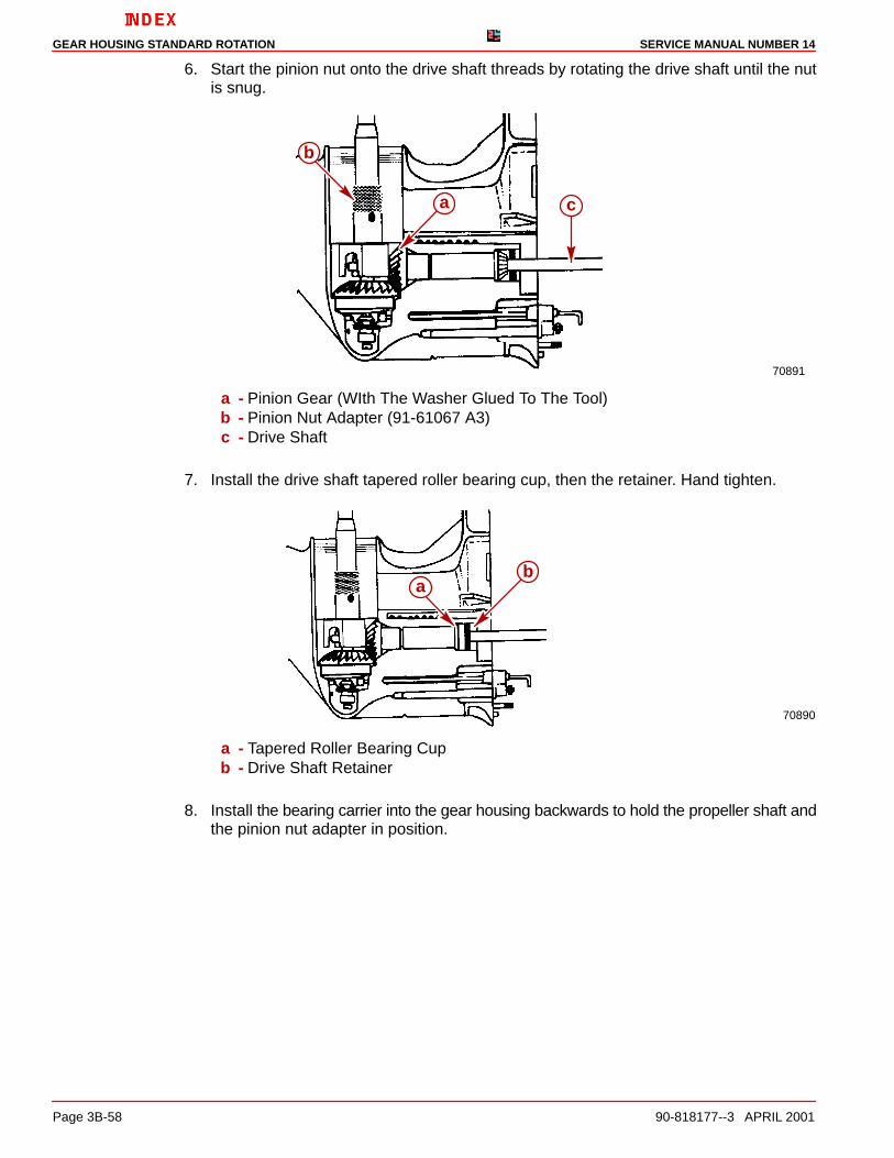
6. Start the pinion nut onto the drive shaft threads by rotating the drive shaft until the nutis snug.
70891
a c
b
a - Pinion Gear (WIth The Washer Glued To The Tool)b - Pinion Nut Adapter (91-61067 A3)c - Drive Shaft
7. Install the drive shaft tapered roller bearing cup, then the retainer. Hand tighten.
70890
ba
a - Tapered Roller Bearing Cupb - Drive Shaft Retainer
8. Install the bearing carrier into the gear housing backwards to hold the propeller shaft andthe pinion nut adapter in position.

GEAR HOUSING STANDARD ROTATIONSERVICE MANUAL NUMBER 14
90-818177--3 APRIL 2001 Page 3B-59
9. Torque the pinion nut (using the tools as shown) to 70 lb-ft (95 Nm).
70892a
c
b
a - Pinion Nut Adaptor (91-61067 A3)b - Drive Shaft Nut Wrench (91-56775)c - Bearing Carrier (Installed Backwards)
10. Remove the bearing carrier, pinion nut adapter, propeller shaft assembly and drive shaftnut wrench.
11. Torque the retainer to 100 lb-ft (130 Nm).
70711
a
a - Drive Shaft Bearing Retainer Wrench (91-43506)

GEAR HOUSING STANDARD ROTATION SERVICE MANUAL NUMBER 14
Page 3B-60 90-818177--3 APRIL 2001
Drive Shaft - Bearing Preload Tool
INSTALLATION
1. Install the components from the Bearing Preload Tool Kit (91-14311A2) over the driveshaft in the order shown.
73885
ab
c
de
f
g
d
a - Top Nut with Threaded Pipeb - Nutc - Springd - Thrust Washere - Thrust Bearingf - Thrust Washerg - Water Pump Face Plate (From Gear Housing)
NOTE: Place the top two nuts as closely together as possible.
2. Pull up on the drive shaft and tighten the two (2) allen screws in the top nut of the bearingpreload tool.
70716
a
a
a - Allen Screws

GEAR HOUSING STANDARD ROTATIONSERVICE MANUAL NUMBER 14
90-818177--3 APRIL 2001 Page 3B-61
3. Screw the bottom nut of the bearing preload tool down until it is one inch further downthe threaded rod than it was previously.
70893
a
a - Bottom Nut [Screwed Down Approximately 1 in. (25 mm) Further Than It WasPreviously]
4. Rotate the drive shaft at least three full turns in a clockwise direction.
Pinion Gear Location
CHECKING AND ADJUSTING
1. Place the pinion gear shimming tool into the gear housing.
NOTE: Take the following measurements at 3 locations, rotating the drive shaft 120 degreesbetween each reading (always rotate the drive shaft in a clockwise direction).
2. Insert the thickest feeler gauge that fits snugly between one tooth of the pinion gear andhigh point of the shimming tool.
3. Rotate the drive shaft 120 degrees in a clockwise direction and take another reading.
4. Repeat this process until 3 readings have been taken.
5. Add the three readings together and divide the sum by 3 to get the average pinion gearheight. Make note of this average measurement.
NOTE: The average pinion gear height should be .025 in. (0.64 mm).

GEAR HOUSING STANDARD ROTATION SERVICE MANUAL NUMBER 14
Page 3B-62 90-818177--3 APRIL 2001
6. If the average pinion gear height is not correct, remove the bearing preload tool, the driveshaft retainer and the drive shaft tapered roller bearing cup. The cup can be removedby wiggling the drive shaft back and forth or by turning gear housing and shaking it. Addor subtract shims beneath the cup to obtain the proper average pinion gear height. Rein-stall the cup and retainer. Retorque retainer to 100 lb-ft (135.8 Nm). Reinstall the bearingpreload tool and rotate the drive shaft at least 3 full turns in a clockwise direction. Re-check the pinion gear height as in Step 5 above. Repeat this process until the averagepinion gear height is within specification.
26410
a b
a
a - Pinion Gear Shimming Tool (91-56048)b - .025 in. (0.64 mm) Feeler Gauge
Bearing Carrier Assembly
INSTALLATION - FOR CHECKING BACKLASHES
1. Place the bearing carrier assembly into the gear housing. It may be necessary to turnthe drive shaft to align the teeth of the pinion and the reverse gears.
70712
a
a - Bearing Carrier Assembly
GEAR HOUSING STANDARD ROTATIONSERVICE MANUAL NUMBER 14
90-818177--3 APRIL 2001 Page 3B-63
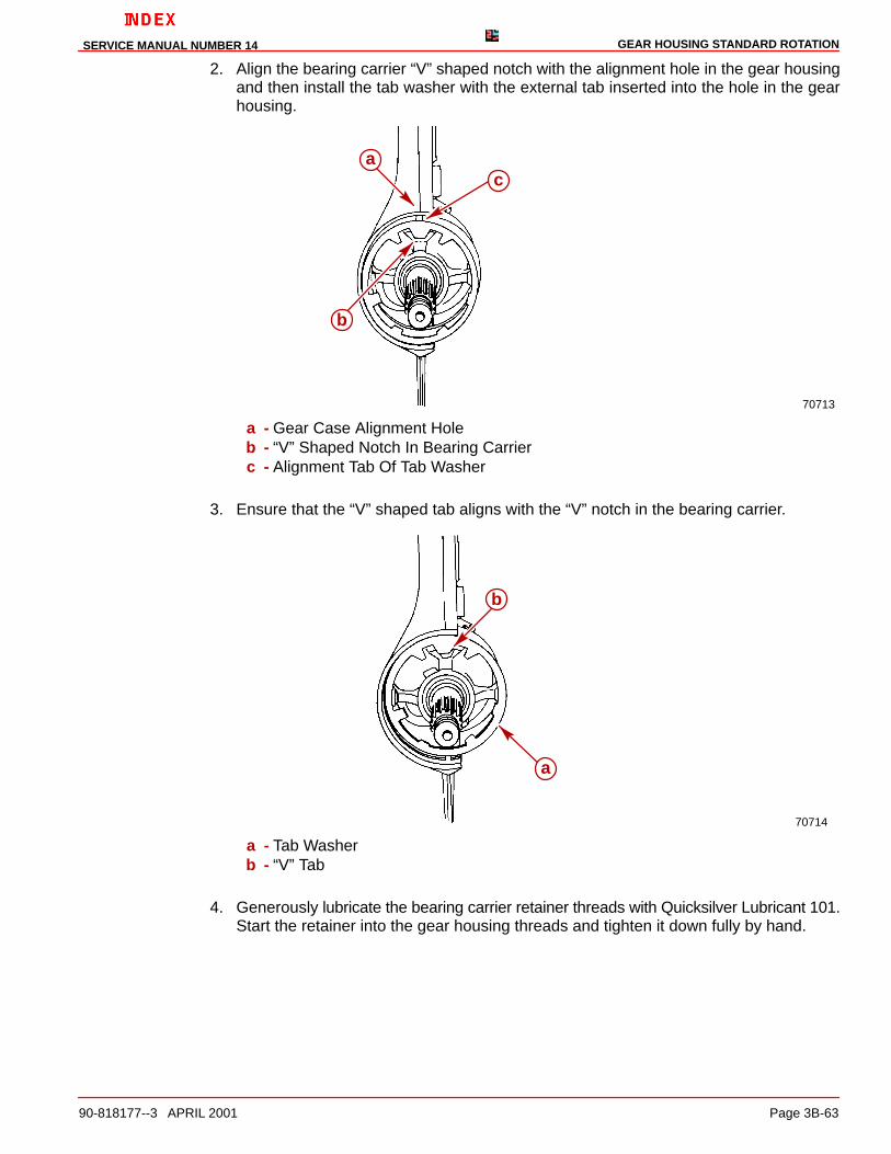
2. Align the bearing carrier “V” shaped notch with the alignment hole in the gear housingand then install the tab washer with the external tab inserted into the hole in the gearhousing.
70713
ac
b
a - Gear Case Alignment Holeb - “V” Shaped Notch In Bearing Carrierc - Alignment Tab Of Tab Washer
3. Ensure that the “V” shaped tab aligns with the “V” notch in the bearing carrier.
70714
a
b
a - Tab Washerb - “V” Tab
4. Generously lubricate the bearing carrier retainer threads with Quicksilver Lubricant 101.Start the retainer into the gear housing threads and tighten it down fully by hand.

GEAR HOUSING STANDARD ROTATION SERVICE MANUAL NUMBER 14
Page 3B-64 90-818177--3 APRIL 2001
5. Torque the bearing carrier retainer to 210 lb-ft (285 Nm).
23355
a
a - Bearing Carrier Retainer Wrench (91-61069)

GEAR HOUSING STANDARD ROTATIONSERVICE MANUAL NUMBER 14
90-818177--3 APRIL 2001 Page 3B-65
Forward Gear Backlash
CHECKING
1. Apply forward pressure to propeller shaft as follows:
a. Attach puller jaws and puller bolt onto bearing carrier bosses, if equipped, or onbearing carrier outer ring and propeller shaft.
70719
a
b
a - Puller Jawsb - Puller Bolt
2. Torque the puller bolt to 45 lb-in. (5 Nm). Rotate the drive shaft three full turns clockwiseand retorque the bolt to 45 lb-in. (5 Nm).
3. For All Gears Except 14:28: Install backlash indicator (P/N 91-58222 A1) and align theindicator pointer so that it is perpendicular to and touching the “I” mark on the indicatorrod.
4. For 14:28 Gears: Install backlash indicator (91-78473) and align the indicator pointerso that it is perpendicular to and touching the “2” mark on the indicator rod.
5. Tighten the indicator rod onto the drive shaft and rotate the drive shaft so that the needlein the dial makes at least one full revolution and comes to “0” on the indicator scale.

GEAR HOUSING STANDARD ROTATION SERVICE MANUAL NUMBER 14
Page 3B-66 90-818177--3 APRIL 2001
77706
edc
b
a
a - Threaded Rod [3/8 in. (9.5 mm) Obtain Locally]b - Dial Indicator Holding Toolc - Backlash Indicatord - Indicator Pointere - Backlash Indicator Rod
6. Take the backlash readings by lightly turning the drive shaft back and forth, so as to feelthe backlash between the gear. No movement should be noticed at the propeller shaft.
a. Observe the backlash indicator and record the reading.
b. Loosen the indicator rod and rotate the drive shaft 90 degrees in a clockwise direc-tion.
c. Repeat Step 2 above and take and record another reading. Repeat Step 3 until atotal of 4 backlash readings have been taken.
7. Add the four readings together and divide the sum by four. This is your average back-lash, make note of this figure, if it does not meet specifications of .017-.028 in. (0.43-0.71mm) it will be adjusted at a later step.
8. Loosen the backlash indicator rod and remove the puller jaws.

GEAR HOUSING STANDARD ROTATIONSERVICE MANUAL NUMBER 14
90-818177--3 APRIL 2001 Page 3B-67
Reverse Gear Backlash
CHECKING
1. Apply backward pressure on the propeller shaft as follows:
a. Install the pinion nut adaptor, washer and propeller nut.
23355
c
ba
a - Pinion Nut Adaptor (91-61061 A2)b - Washer (12-54048)c - Prop Nut
b. Torque the propeller nut to 45 lb-in. (5 Nm). Rotate the drive shaft 3 full turns in aclockwise direction and retorque the propeller nut to 45 lb-in. (5 Nm).
2. For All Gears Except 14:28: Install backlash indicator (P/N 91-58222 A1) and align theindicator pointer so that it is perpendicular to and touching the “I” mark on the backlashindicator rod.
3. For 14:28 Gears: Install backlash indicator (91-78473) and align the indicator pointerso that it is perpendicular to and touching the “2” mark on the backlash indicator rod.
GEAR HOUSING STANDARD ROTATION SERVICE MANUAL NUMBER 14
Page 3B-68 90-818177--3 APRIL 2001
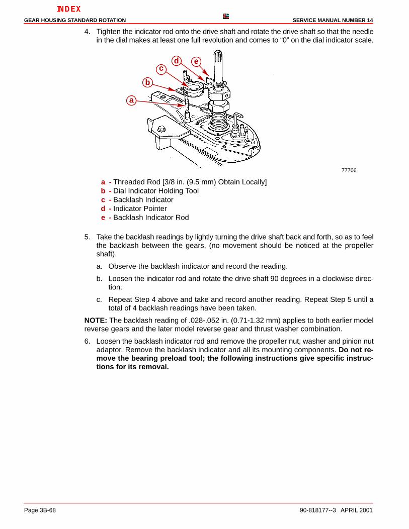
4. Tighten the indicator rod onto the drive shaft and rotate the drive shaft so that the needlein the dial makes at least one full revolution and comes to “0” on the dial indicator scale.
77706
edc
b
a
a - Threaded Rod [3/8 in. (9.5 mm) Obtain Locally]b - Dial Indicator Holding Toolc - Backlash Indicatord - Indicator Pointere - Backlash Indicator Rod
5. Take the backlash readings by lightly turning the drive shaft back and forth, so as to feelthe backlash between the gears, (no movement should be noticed at the propellershaft).
a. Observe the backlash indicator and record the reading.
b. Loosen the indicator rod and rotate the drive shaft 90 degrees in a clockwise direc-tion.
c. Repeat Step 4 above and take and record another reading. Repeat Step 5 until atotal of 4 backlash readings have been taken.
NOTE: The backlash reading of .028-.052 in. (0.71-1.32 mm) applies to both earlier modelreverse gears and the later model reverse gear and thrust washer combination.
6. Loosen the backlash indicator rod and remove the propeller nut, washer and pinion nutadaptor. Remove the backlash indicator and all its mounting components. Do not re-move the bearing preload tool; the following instructions give specific instruc-tions for its removal.

GEAR HOUSING STANDARD ROTATIONSERVICE MANUAL NUMBER 14
90-818177--3 APRIL 2001 Page 3B-69
Forward and/or Reverse Gear Backlash Adjustment
SPECIFICATION
inches millimeters
Forward Gear Backlash .017-.028 0.43-0.71
Reverse Gear Backlash .028-.060 0.71-1.32
1. If the forward gear backlash is not within specification
a. Ensure that the bearing is all the way onto the gear.
b. Ensure that the bearing race is all the way into the gear housing.
c. Ensure that appropriate amount of shims were installed beneath forward gear bear-ing cup.
2. If the reverse gear backlash is not within specification
a. Check that bearing is completely pressed on gear.
b. Check bearing carrier assembly to ensure reverse gear bearing is completelyseated in the bearing carrier.
c. Check bearing carrier I.D. If oversize, replace bearing carrier.
Drive Shaft - Bearing Preload Tool
REMOVAL
CAUTIONBefore loosening the top nut allen screws of the bearing preload tool, screw the bot-tom nut up as close as possible to the top nut or shaft will be damaged.
1. Loosen the bottom nut of the bearing preload tool until it is as close as possible to topnut.
2. Loosen the allen screws in the top nut.
3. Remove all components including the water pump face plate.
70716
c
a
b
a - Top Nut (With Allen Screws)b - Bottom Nutc - Water Pump Face Plate

GEAR HOUSING STANDARD ROTATION SERVICE MANUAL NUMBER 14
Page 3B-70 90-818177--3 APRIL 2001
Bearing Carrier Assembly
Final Installation1. Remove the Bearing Carrier and lubricate the following as specified:
a. Lubricate both the forward and aft outer diameters of the bearing carrier with Quick-silver Perfect Seal.
b. Fill the space between the carrier oil seals with Quicksilver 2-4-C Marine Lubricantwith Teflon.
2. Place the bearing carrier assembly into the gear housing. It may be necessary to turnthe drive shaft to align the teeth of the pinion and the reverse gears.
70712
a
a - Bearing Carrier Assembly
3. Align the bearing carrier “V” shaped notch with the alignment hole in the gear housingand then install the tab washer with the external tab inserted into the hole in the gearhousing.
70713
a
c
b
a - Gear Case Alignment Holeb - “V” Shaped Notch In Bearing Carrierc - Alignment Tab Of Tab Washer

GEAR HOUSING STANDARD ROTATIONSERVICE MANUAL NUMBER 14
90-818177--3 APRIL 2001 Page 3B-71
4. Ensure that the “V” shaped tab aligns with the “V” notch in bearing carrier.
70714
a
b
a - Tab Washerb - “V” Tab
5. Generously lubricate the bearing carrier retainer threads with Quicksilver Lubricant 101.Start the retainer into the gear housing threads and screw it down fully by hand.
70715
a
a - Bearing Carrier Retainer

GEAR HOUSING STANDARD ROTATION SERVICE MANUAL NUMBER 14
Page 3B-72 90-818177--3 APRIL 2001
6. Torque the bearing carrier retainer to 210 lb-ft (285 Nm). Ensure that one tab lines upin the notched space between two of the retainer teeth. Tighten the retainer further, ifnecessary.
23355
a
a - Bearing Carrier Retainer Wrench (91-61069)
7. Bend one tab aft (outward) into a space between two of the notches of the retainer. Bendall the remaining tabs forward (inward).
70490
a
b
c
a - Bearing Carrierb - Tabc - Retainer Notches

GEAR HOUSING STANDARD ROTATIONSERVICE MANUAL NUMBER 14
90-818177--3 APRIL 2001 Page 3B-73
8. If equipped, install anode plate to bearing carrier.
71958
a
b
a - Anodeb - Screws

GEAR HOUSING STANDARD ROTATION SERVICE MANUAL NUMBER 14
Page 3B-74 90-818177--3 APRIL 2001
Oil Seal Carrier Assembly
InstallationNOTE: Do not hammer the oil seal carrier into position, apply hand pressure only to install.
1. Lubricate the oil seal carrier oil seal lips and O-ring with Quicksilver 2-4-C Marine Lubri-cant with Teflon and install the oil seal carrier over the drive shaft and into the gear case.
70501
a
b
c
a - Oil Seal Carrierb - Oil Seal Lipsc - O-ring
75685
c
b
a
a - Drive Shaftb - Oil Seal Carrierc - Retainer Nut

GEAR HOUSING STANDARD ROTATIONSERVICE MANUAL NUMBER 14
90-818177--3 APRIL 2001 Page 3B-75
Water Pump Assembly
InstallationNOTE: The aluminum dam has been changed to a rubber filler plug. If the aluminum waterpump dam in the gear housing has become corroded or damaged, it can be replaced withthe rubber filler plug.
IMPORTANT: The gaskets/face plate hole pattern is not symmetrical. If the holes ofthe gaskets/face plate do not align with the screw holes of the gear case and/or eachother, one or more of the parts is upside down. Determine which part(s) is (are) upsidedown and turn the appropriate part(s) over.
1. Apply Quicksilver Perfect Seal to the small hole gasket. Place the small hole gasket, theface plate and the large hole gasket onto the gear case.
NOTE: Add Quicksilver Perfect Seal to the gasket to seal it and prevent water from seepinginto the gear housing.
70720
a
bc
a - Small Hole Gasketb - Face Platec - Large Hole Gasket
2. Place a small amount of Quicksilver 2-4-C Marine Lubricant with Teflon on the flat sur-face of the impeller key and assemble the key onto the drive shaft keyway.
IMPORTANT: When using an impeller whose blades have taken a set, face the curl ofthe blades in a counterclockwise direction. DO NOT install the impeller with itsblades oriented in a reversed direction from original rotation, or premature impellerfailure will occur.

GEAR HOUSING STANDARD ROTATION SERVICE MANUAL NUMBER 14
Page 3B-76 90-818177--3 APRIL 2001
3. Assemble the water pump impeller onto the drive shaft and down over the key.
70721
a
b
a - Water Pump Impellerb - Water Pump Impeller Key
4. On early models, install the two (2) water pump locating pins through the gaskets andface plate.
5. Position the water pump body over the drive shaft and water pump locating pins. Rotatethe drive shaft in a clockwise direction, while pushing down on the water pump body toease the water pump over the impeller blades.
70722
a
b
a - Water Pump Bodyb - Water Pump Alignment Pins (91-821571A1)c - Drive Shaft (Turn Clockwise While Installing Water Pump Body)
NOTE: Apply Quicksilver Perfect Seal to all four(4) screw threads before installation.
6. Hand start two (2) fasteners into the water pump assembly and remove the water pumplocating pins. Assemble the remaining two (2) fasteners. Run all fasteners down andtorque to 60 lb-in. (7.9 Nm).
IMPORTANT: The water pump face seal must be installed as outlined below. Improp-erly installing the water pump face seal may result in premature failure of the unit.

GEAR HOUSING STANDARD ROTATIONSERVICE MANUAL NUMBER 14
90-818177--3 APRIL 2001 Page 3B-77
7. Assemble the water pump face seal to a position approximately 1/2 of the way down thedrive shaft. Assemble the water pump face seal setting tool over the drive shaft and pushthe seal down onto the water pump with the tool while pulling up on the drive shaft. Re-move the tool from the drive shaft.
70708
70504
a
b
a
a - Water Pump Face Sealb - Water Pump Face Seal Setting Tool
8. Lightly lubricate the O-rings in the water tube coupling with Quicksilver 2-4-C Marine Lu-bricant with Teflon. Assemble the water tube sleeve into the water tube coupling.
9. Assemble the water tube coupling assembly to the water pump ensuring that the O-ringsare not damaged during assembly.

GEAR HOUSING STANDARD ROTATION SERVICE MANUAL NUMBER 14
Page 3B-78 90-818177--3 APRIL 2001
Joining Drive Shaft Housing/Gear Housing
1. Lubricate the end of the water tube (in the drive shaft housing) and the splines of thedrive shaft with Quicksilver 2-4-C Marine Lubricant with Teflon.
NOTE: The aluminum dam has been changed to a rubber filler plug. If the aluminum waterpump dam in the gear housing has become corroded or damaged, it can be replaced withthe rubber filler plug.
IMPORTANT: Ensure that the drain hole of the aluminum water pump dam is notclogged with any foreign material as damage may occur if it is.
71436
71410
ca
b
a - Aluminum Damb - Rubber Filler Plugc - Drain Hole
2. Units with an aluminum dam installed in them will require a bead of Permatex Ultra BlueSilicone Sealant along the top of the water pump dam as shown. If rubber filler plug ispresent, it is not necessary to use this sealant.
3. To replace the aluminum dam if it has been removed and undamaged, place a bead ofPermatex Ultra Blue Silicone Sealant down both sides of it.

GEAR HOUSING STANDARD ROTATIONSERVICE MANUAL NUMBER 14
90-818177--3 APRIL 2001 Page 3B-79
4. Ensure that the water pump dam in the drive shaft housing is present and installed cor-rectly. Ensure that all parts are present on the gear housing and the drive shaft housing.
70710
a
cb
d
a - Drive Shaft Splinesb - Sealant - Aluminum Dam Onlyc - Trim Tab Bolt (Insert In Aft Hole)d - Quad Ring
5. Position the drive shaft housing straight above the gear housing. Align the water tubesleeve with the water tube and the drive shaft with the upper drive gear and assemblethe drive shaft housing to the gear housing. It may be necessary to rotate the propellershaft or the u-joint to align the drive shaft splines with the upper drive gear splines.
6. Assemble the front nut to the front stud of the unit.
7. Assemble the aft screw and star washer (into the forward hole in the trim tab well of thegear housing).
8. Assemble the bolts, nuts and washers to the port and starboard sides of the unit. Torqueto 35 lb.ft. (47.5 Nm).
70117
a
cb
a - Nuts, Bolts, Washersb - Nutc - Screw
9. Assemble the trim tab and align it to the mark made previously on the gear housing.Torque the screw to 23 lb-ft (31 Nm).

GEAR HOUSING STANDARD ROTATION SERVICE MANUAL NUMBER 14
Page 3B-80 90-818177--3 APRIL 2001
10. Position or lower drive unit so anti-ventilation plate is level.
11. Refill drive unit with gear lube. Refer to section 1B.
GEAR HOUSING STANDARD ROTATIONSERVICE MANUAL NUMBER 14
90-818177--3 APRIL 2001 Page 3B-81
THIS PAGE IS INTENTIONALLY BLANK

GEAR HOUSING STANDARD ROTATION SERVICE MANUAL NUMBER 14
Page 3B-82 90-818177--3 APRIL 2001
THIS PAGE IS INTENTIONALLY BLANK