service manual - #numeralkod | about of parts 212...asm-0025e - 212 axle service manual dana holding...
TRANSCRIPT
Service Manual
Axle 212
October 2013ASM-0025E

3Dana Holding CorporationASM-0025E - 212 Axle Service Manual
CONTENTS
INTRODUCTION ................................................................................................................................ 7
SPECIFICATIONS ..............................................................................................................................9
DEFINITION OF VIEWPOINTS ................................................................................................................. 9DATA PLATE ............................................................................................................................................ 9
CONVERSION TABLES ................................................................................................................................ 10TORQUE SPECIFICATIONS ......................................................................................................................... 11
COARSE PITCH ....................................................................................................................................... 11FINE PITCH .............................................................................................................................................. 11WHEEL NUT TIGHTENING TORQUES .................................................................................................... 12
MAINTENANCE ............................................................................................................................................ 13MAINTENANCE POINTS ......................................................................................................................... 13MAINTENANCE INTERVALS ................................................................................................................... 14ADJUSTMENT AND CHECKS ................................................................................................................. 14LUBRICANT & SEALANT SPECIFICATIONS ........................................................................................... 15
SAFETY PRECAUTIONS ...................................................................................................................17
CHECKING WEAR AND REPLACING THE BRAKING DISCS ........................................................ 19
EXPLODED VIEW .......................................................................................................................................... 19DISASSEMBLY ............................................................................................................................................. 20ASSEMBLY ................................................................................................................................................... 22SPECIAL TOOLS .......................................................................................................................................... 24
T1 ............................................................................................................................................................. 24T2 ............................................................................................................................................................. 24
COMPLETE STEERING CASE .......................................................................................................... 25
EXPLODED VIEW .......................................................................................................................................... 25DISASSEMBLY ............................................................................................................................................. 26ASSEMBLY ................................................................................................................................................... 27
DOUBLE U-JOINT ............................................................................................................................. 29
EXPLODED VIEW .......................................................................................................................................... 29DISASSEMBLY ............................................................................................................................................. 30ASSEMBLY ................................................................................................................................................... 31SPECIAL TOOLS .......................................................................................................................................... 33
T1 ............................................................................................................................................................. 33T2 ............................................................................................................................................................. 33
PLANETARY REDUCTION GEAR .................................................................................................... 35
EXPLODED VIEW .......................................................................................................................................... 35DISASSEMBLY ............................................................................................................................................. 36ASSEMBLY ................................................................................................................................................... 40SPECIAL TOOLS .......................................................................................................................................... 44
T1 ............................................................................................................................................................. 44T2 ............................................................................................................................................................. 44T3 ............................................................................................................................................................. 45T4 ............................................................................................................................................................. 46T5 ............................................................................................................................................................. 46
STEERING CYLINDER ...................................................................................................................... 47
EXPLODED VIEW .......................................................................................................................................... 47OPTICAL SENSOR AND MAGNETIC SENSOR ............................................................................................ 48DISASSEMBLY ............................................................................................................................................. 49ASSEMBLY ................................................................................................................................................... 52SPECIAL TOOLS .......................................................................................................................................... 58
T1 ............................................................................................................................................................. 58T2 ............................................................................................................................................................. 59
4 Dana Holding Corporation ASM-0025E - 212 Axle Service Manual
DIFFERENTIAL UNIT ........................................................................................................................ 61
EXPLODED VIEW .......................................................................................................................................... 61DISASSEMBLY ............................................................................................................................................. 62ASSEMBLY ................................................................................................................................................... 64SPECIAL TOOLS .......................................................................................................................................... 66
T1 ............................................................................................................................................................. 66T2 ............................................................................................................................................................. 66
BEVEL PINION ................................................................................................................................... 67
EXPLODED VIEW .......................................................................................................................................... 67DISASSEMBLY ............................................................................................................................................. 68ASSEMBLY ................................................................................................................................................... 71SPECIAL TOOLS .......................................................................................................................................... 77
T1 ............................................................................................................................................................. 77T2 ............................................................................................................................................................. 78T3 ............................................................................................................................................................. 78T4 ............................................................................................................................................................. 79T5 ............................................................................................................................................................. 79T6 ............................................................................................................................................................. 80T7 ............................................................................................................................................................. 81T8 ............................................................................................................................................................. 82T9 ............................................................................................................................................................. 82
MANUAL EMERGENCY RELASE .....................................................................................................83
EXPLODED VIEW .......................................................................................................................................... 83RELEASE ...................................................................................................................................................... 84ADJUST ........................................................................................................................................................ 85
MECHANICAL PARKING BRAKE .................................................................................................... 87
EXPLODED VIEW .......................................................................................................................................... 87DISASSEMBLY ............................................................................................................................................. 88ASSEMBLY ................................................................................................................................................... 90
EXTERNAL HYDRAULIC NEGATIVE BRAKE .................................................................................. 93
EXPLODED VIEW .......................................................................................................................................... 93DISASSEMBLY ............................................................................................................................................. 94ASSEMBLY ................................................................................................................................................... 95
EXTERNAL HYDRAULIC NEGATIVE BRAKE WITH QUICK RELEASE ......................................... 97
EXPLODED VIEW .......................................................................................................................................... 97DISASSEMBLY ............................................................................................................................................. 98ASSEMBLY ................................................................................................................................................... 100
INCOMING DRUM BRAKE ............................................................................................................... 103
EXPLODED VIEW .......................................................................................................................................... 103DISASSEMBLY ............................................................................................................................................. 104ASSEMBLY ................................................................................................................................................... 106SPECIAL TOOLS .......................................................................................................................................... 108
T1 ............................................................................................................................................................. 108T2 ............................................................................................................................................................. 109
4" INCOMING BRAKE (2 AND 3 FUNCTION VERSIONS) ............................................................... 111
EXPLODED VIEW .......................................................................................................................................... 111DISASSEMBLY ............................................................................................................................................. 112ASSEMBLY ................................................................................................................................................... 116SPECIAL TOOLS .......................................................................................................................................... 122
T1 ............................................................................................................................................................. 122T2 ............................................................................................................................................................. 122T3 ............................................................................................................................................................. 123
5Dana Holding CorporationASM-0025E - 212 Axle Service Manual
NORMAL DIFFERENTIAL UNIT ........................................................................................................125
EXPLODED VIEW .......................................................................................................................................... 125DISASSEMBLY ............................................................................................................................................. 126ASSEMBLY ................................................................................................................................................... 128SPECIAL TOOLS .......................................................................................................................................... 131
T1 ............................................................................................................................................................. 131T2 ............................................................................................................................................................. 131T3 ............................................................................................................................................................. 132T4 ............................................................................................................................................................. 132
LIMITED SLIP DIFFERENTIAL UNIT (25% AND 45%) ....................................................................133
EXPLODED VIEW .......................................................................................................................................... 133DISASSEMBLY ............................................................................................................................................. 134ASSEMBLY ................................................................................................................................................... 137SPECIAL TOOLS .......................................................................................................................................... 140
T1 ............................................................................................................................................................. 140T2 ............................................................................................................................................................. 140T3 ............................................................................................................................................................. 141T4 ............................................................................................................................................................. 141
HYDRAULIC DIFFERENTIAL LOCK .................................................................................................143
EXPLODED VIEW .......................................................................................................................................... 143DISASSEMBLY ............................................................................................................................................. 144ASSEMBLY ................................................................................................................................................... 147SPECIAL TOOLS .......................................................................................................................................... 149
T1 ............................................................................................................................................................. 149T2 ............................................................................................................................................................. 149
HYDRAULIC NEGATIVE BRAKE ...................................................................................................... 151
EXPLODED VIEW .......................................................................................................................................... 151DISASSEMBLY ............................................................................................................................................. 152ASSEMBLY ................................................................................................................................................... 155
INCORPORATED REDUCTION GEAR AND PINION 602 ............................................................... 161
EXPLODED VIEW .......................................................................................................................................... 161DISASSEMBLY ............................................................................................................................................. 162ASSEMBLY ................................................................................................................................................... 166SPECIAL TOOLS .......................................................................................................................................... 169
T1 ............................................................................................................................................................. 169T2 ............................................................................................................................................................. 170T3 ............................................................................................................................................................. 171T4 ............................................................................................................................................................. 172T5 ............................................................................................................................................................. 173T6 ............................................................................................................................................................. 174

6 Dana Holding Corporation ASM-0025E - 212 Axle Service Manual
7Dana Holding CorporationASM-0025E - 212 Axle Service Manual
INTRODUCTION
The efficiency and continued operation of mechanical units depend on constant, correct maintenance and also on efficient re-pair work, should there be a break-down or malfunction. The instructions contained in this manual have been based on a com-plete overhaul of the unit. However, it is up to the mechanic to decide whether or not it is necessary to assemble only individual components, when partial repair work is needed. The manual provides a quick and sure guide which, with the use of photogra-phs and diagrams illustrating the various phases of the operations, allows accurate work to be performed.All the information needed for correct disassembly, checks and assembly of each individual component is set out below. In order to remove the differential unit from the vehicle, the manuals provided by the vehicle manufacturer should be consulted. In describing the fol-lowing operations it is presumed that the unit has already been removed from the vehicle.
IMPORTANT: In order to facilitate work and protect both working surfaces and operators, it is advisable to use proper equip-ment such as: trestles or supporting benches, plastic or copper hammers, appropriate levers, pullers and specific spanners or wrenches. Before going on to disassemble the parts and drain the oil, it is best to thoroughly clean the unit, removing any en-crusted or accumulated grease.
INTRODUCTORY REMARKS: All the disassembled mechanical units should be thoroughly cleaned with appropriate products and restored or replaced if damage, wear, cracking or seizing have occurred. In particular, thoroughly check the condition of all moving parts (bearings, gears, ring gear and pinion, shafts) and sealing parts (o-rings, oil shields) which are subject to major stress and wear. In any case, it is advisable to replace the seals every time a component is overhauled or repaired. During as-sembly, the sealing rings must be lubricated on the sealing edge. In the case of the ring gear and pinion, replacement of one component requires the replacement of the other one. During assembly, the prescribed pre-loading, backlash and torque of parts must be maintained.
CLASSIFICATION: This manual classifies units according to part numbers. For a correct interpretation, classification is indica-ted as follows:
�����= up to the part number
�����= from the part number on
When no classification is given, disassembly and assembly operations are the same for all versions.
SPECIFIC EQUIPMENT AND SPARE PARTS: The drawings of all specific tools required for maintenance and repair work can be found at the end of this manual ; spare parts may be ordered either from the vehicle manufacturer or directly from the Service Centers or Authorized Distributors of SPICER.

8 Dana Holding Corporation ASM-0025E - 212 Axle Service Manual
9Dana Holding CorporationASM-0025E - 212 Axle Service Manual
SPECIFICATIONS
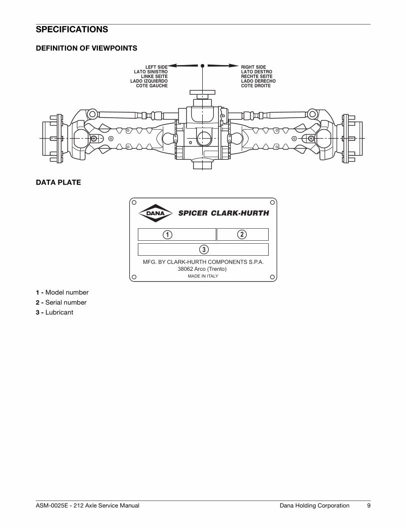
DEFINITION OF VIEWPOINTS
DATA PLATE
1 - Model number
2 - Serial number
3 - Lubricant
MFG. BY CLARK-HURTH COMPONENTS S.P.A.38062 Arco (Trento)
MADE IN ITALY
3
21
10
CONVERSION TABLES
Dana Holding Corporation ASM-0025E - 212 Axle Service Manual
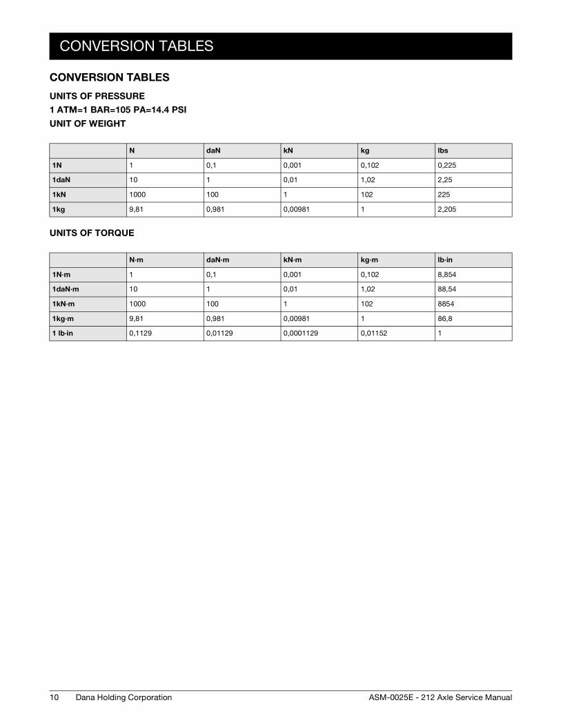
CONVERSION TABLES
UNITS OF PRESSURE
1 ATM=1 BAR=105 PA=14.4 PSI
UNIT OF WEIGHT
UNITS OF TORQUE
N daN kN kg lbs
1N 1 0,1 0,001 0,102 0,225
1daN 10 1 0,01 1,02 2,25
1kN 1000 100 1 102 225
1kg 9,81 0,981 0,00981 1 2,205
N·m daN·m kN·m kg·m lb·in
1N·m 1 0,1 0,001 0,102 8,854
1daN·m 10 1 0,01 1,02 88,54
1kN·m 1000 100 1 102 8854
1kg·m 9,81 0,981 0,00981 1 86,8
1 lb·in 0,1129 0,01129 0,0001129 0,01152 1
TORQUE SPECIFICATIONS
11Dana Holding CorporationASM-0025E - 212 Axle Service Manual
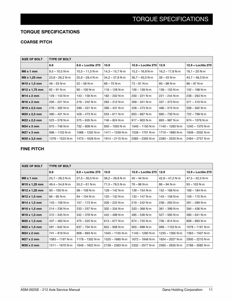
TORQUE SPECIFICATIONS
COARSE PITCH
FINE PITCH
SIZE OF BOLT TYPE OF BOLT
8.8 8.8 + Loctite 270 10.9 10.9 + Loctite 270 12.9 12.9 + Loctite 270
M6 x 1 mm 9,5 – 10,5 N·m 10,5 – 11,5 N·m 14,3 – 15,7 N·m 15,2 – 16,8 N·m 16,2 – 17,8 N·m 18,1 – 20 N·m
M8 x 1,25 mm 23,8 – 26,2 N·m 25,6 – 28,4 N·m 34,2 – 37,8 N·m 36,7 – 40,5 N·m 39 – 43 N·m 43,7 – 48,3 N·m
M10 x 1,5 mm 48 – 53 N·m 52 – 58 N·m 68 – 75 N·m 73 – 81 N·m 80 – 88 N·m 88 – 97 N·m
M12 x 1,75 mm 82 – 91 N·m 90 – 100 N·m 116 – 128 N·m 126 – 139 N·m 139 – 153 N·m 152 – 168 N·m
M14 x 2 mm 129 – 143 N·m 143 – 158 N·m 182 – 202 N·m 200 – 221 N·m 221 – 244 N·m 238 – 263 N·m
M16 x 2 mm 200 – 221 N·m 219 – 242 N·m 283 – 312 N·m 309 – 341 N·m 337 – 373 N·m 371 – 410 N·m
M18 x 2,5 mm 276 – 305 N·m 299 – 331 N·m 390 – 431 N·m 428 – 473 N·m 466 – 515 N·m 509 – 562 N·m
M20 x 2,5 mm 390 – 431 N·m 428 – 473 N·m 553 – 611 N·m 603 – 667 N·m 660 – 730 N·m 722 – 798 N·m
M22 x 2,5 mm 523 – 578 N·m 575 – 635 N·m 746 – 824 N·m 817 – 903 N·m 893 – 987 N·m 974 – 1076 N·m
M24 x 3 mm 675 – 746 N·m 732 – 809 N·m 950 – 1050 N·m 1040 – 1150 N·m 1140 – 1260 N·m 1240 – 1370 N·m
M27 x 3 mm 998 – 1103 N·m 1088 – 1202 N·m 1411 – 1559 N·m 1539 – 1701 N·m 1710 – 1890 N·m 1838 – 2032 N·m
M30 x 3,5 mm 1378 – 1523 N·m 1473 – 1628 N·m 1914 – 2115 N·m 2085 – 2305 N·m 2280 – 2520 N·m 2494 – 2757 N·m
SIZE OF BOLT TYPE OF BOLT
8.8 8.8 + Loctite 270 10.9 10.9 + Loctite 270 12.9 12.9 + Loctite 270
M8 x 1 mm 25,7 – 28,3 N·m 27,5 – 30,5 N·m 36,2 – 39,8 N·m 40 – 44 N·m 42,8 – 47,2 N·m 47,5 – 52,5 N·m
M10 x 1,25 mm 49,4 – 54,6 N·m 55,2 – 61 N·m 71,5 – 78,5 N·m 78 – 86 N·m 86 – 94 N·m 93 – 103 N·m
M12 x 1,25 mm 90 – 100 N·m 98 – 109 N·m 128 – 142 N·m 139 – 154 N·m 152 – 168 N·m 166 – 184 N·m
M12 x 1,5 mm 86 – 95 N·m 94 – 104 N·m 120 – 132 N·m 133 – 147 N·m 143 – 158 N·m 159 – 175 N·m
M14 x 1,5 mm 143 – 158 N·m 157 – 173 N·m 200 – 222 N·m 219 – 242 N·m 238 – 263 N·m 261 – 289 N·m
M16 x 1,5 mm 214 – 236 N·m 233 – 257 N·m 302 – 334 N·m 333 – 368 N·m 361 – 399 N·m 394 – 436 N·m
M18 x 1,5 mm 312 – 345 N·m 342 – 378 N·m 442 – 489 N·m 485 – 536 N·m 527 – 583 N·m 580 – 641 N·m
M20 x 1,5 mm 437 – 483 N·m 475 – 525 N·m 613 – 677 N·m 674 – 745 N·m 736 – 814 N·m 808 – 893 N·m
M22 x 1,5 mm 581 – 642 N·m 637 – 704 N·m 822 – 908 N·m 903 – 998 N·m 998 – 1103 N·m 1078 – 1191 N·m
M24 x 2 mm 741 – 819 N·m 808 – 893 N·m 1045 – 1155 N·m 1140 – 1260 N·m 1235 – 1365 N·m 1363 – 1507 N·m
M27 x 2 mm 1083 – 1197 N·m 1178 – 1302 N·m 1520 – 1680 N·m 1672 – 1848 N·m 1834 – 2027 N·m 2000 – 2210 N·m
M30 x 2 mm 1511 – 1670 N·m 1648 – 1822 N·m 2138 – 2363 N·m 2332 – 2577 N·m 2565 – 2835 N·m 2788 – 3082 N·m
12
TORQUE SPECIFICATIONS
Dana Holding Corporation ASM-0025E - 212 Axle Service Manual
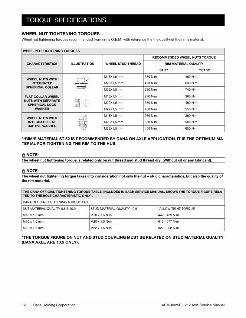
WHEEL NUT TIGHTENING TORQUES
Wheel nut tightening torques recommended from rim's O.E.M. with reference the the quality of the rim's material.
**RIM'S MATERIAL ST 52 IS RECOMMENDED BY DANA ON AXLE APPLICATION. IT IS THE OPTIMUM MA-
TERIAL FOR TIGHTENING THE RIM TO THE HUB.
*THE TORQUE FIGURE ON NUT AND STUD COUPLING MUST BE RELATED ON STUD MATERIAL QUALITY
(DANA AXLE ARE 10.9 ONLY).
WHEEL NUT TIGHTENING TORQUES
CHARACTERISTICS ILLUSTRATION WHEEL STUD THREAD
RECOMMENDED WHEEL NUTS TORQUE
RIM MATERIAL QUALITY
ST 37 **ST 52
WHEEL NUTS WITH
INTEGRATED
SPHERICAL COLLAR
M18X1,5 mm 330 N·m 460 N·m
M20X1,5 mm 490 N·m 630 N·m
M22X1,5 mm 630 N·m 740 N·m
FLAT COLLAR WHEEL
NUTS WITH SEPARATE
SPHERICAL LOCK
WASHER
M18X1,5 mm 270 N·m 360 N·m
M20X1,5 mm 360 N·m 450 N·m
M22X1,5 mm 460 N·m 550 N·m
WHEEL NUTS WITH
INTEGRATE SEAT
CAPTIVE WASHER
M18X1,5 mm 260 N·m 360 N·m
M20X1,5 mm 350 N·m 500 N·m
M22X1,5 mm 450 N·m 650 N·m
NOTE:
The wheel nut tightening torque is related only on nut thread and stud thread dry. (Without oil or any lubricant).
NOTE:
The wheel nut tightening torque takes into consideration not only the nut + stud characteristics, but also the quality of
the rim material.
THE DANA OFFICIAL TIGHTENING TORQUE TABLE, INCLUDED IN EACH SERVICE MANUAL, SHOWS THE TORQUE FIGURE RELA-
TED TO THE BOLT CHARACTERISTIC ONLY .
DANA OFFICIAL TIGHTENING TORQUE TABLE
NUT MATERIAL QUALITY 8.8 & 10.9 STUD MATERIAL QUALITY 10.9 *ALLOW TIGHT TORQUE
M18 x 1,5 mm M18 x 1,5 N·m 442 - 489 N·m
M20 x 1,5 mm M20 x 1,5 N·m 613 - 677 N·m
M22 x 1,5 mm M22 x 1,5 N·m 822 - 908 N·m
MAINTENANCE
13Dana Holding CorporationASM-0025E - 212 Axle Service Manual
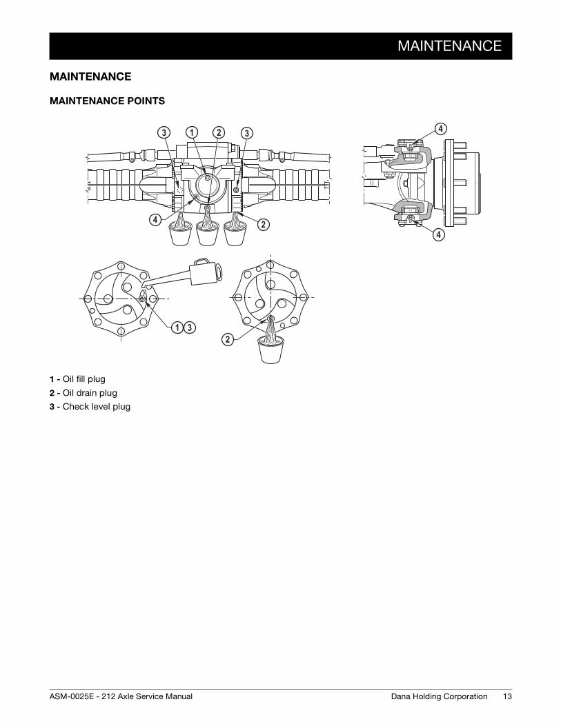
MAINTENANCE
MAINTENANCE POINTS
1 - Oil fill plug
2 - Oil drain plug
3 - Check level plug
3 1 3 4
4
2
2
12
3
4
14
MAINTENANCE
Dana Holding Corporation ASM-0025E - 212 Axle Service Manual
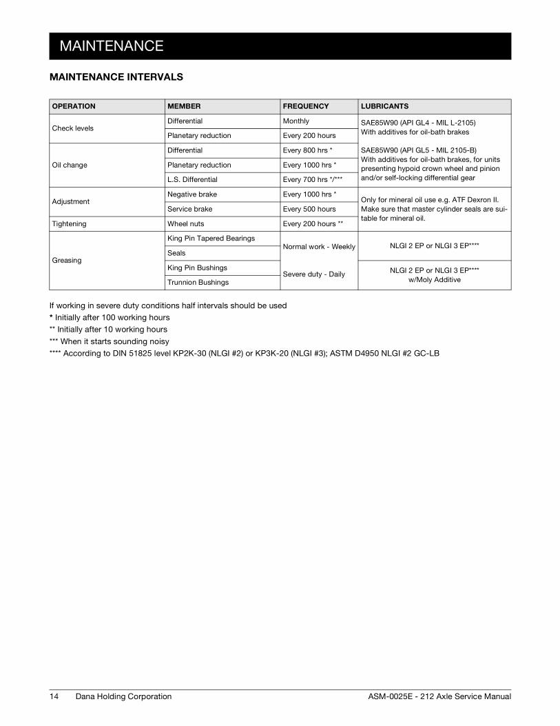
MAINTENANCE INTERVALS
If working in severe duty conditions half intervals should be used
* Initially after 100 working hours
** Initially after 10 working hours
*** When it starts sounding noisy
**** According to DIN 51825 level KP2K-30 (NLGI #2) or KP3K-20 (NLGI #3); ASTM D4950 NLGI #2 GC-LB
OPERATION MEMBER FREQUENCY LUBRICANTS
Check levelsDifferential Monthly SAE85W90 (API GL4 - MIL L-2105)
With additives for oil-bath brakes
SAE85W90 (API GL5 - MIL 2105-B)With additives for oil-bath brakes, for units presenting hypoid crown wheel and pinion and/or self-locking differential gear
Planetary reduction Every 200 hours
Oil change
Differential Every 800 hrs *
Planetary reduction Every 1000 hrs *
L.S. Differential Every 700 hrs */***
AdjustmentNegative brake Every 1000 hrs *
Only for mineral oil use e.g. ATF Dexron II. Make sure that master cylinder seals are sui-table for mineral oil.
Service brake Every 500 hours
Tightening Wheel nuts Every 200 hours **
Greasing
King Pin Tapered BearingsNormal work - Weekly
Severe duty - Daily
NLGI 2 EP or NLGI 3 EP****Seals
King Pin Bushings NLGI 2 EP or NLGI 3 EP****w/Moly AdditiveTrunnion Bushings
MAINTENANCE
15Dana Holding CorporationASM-0025E - 212 Axle Service Manual
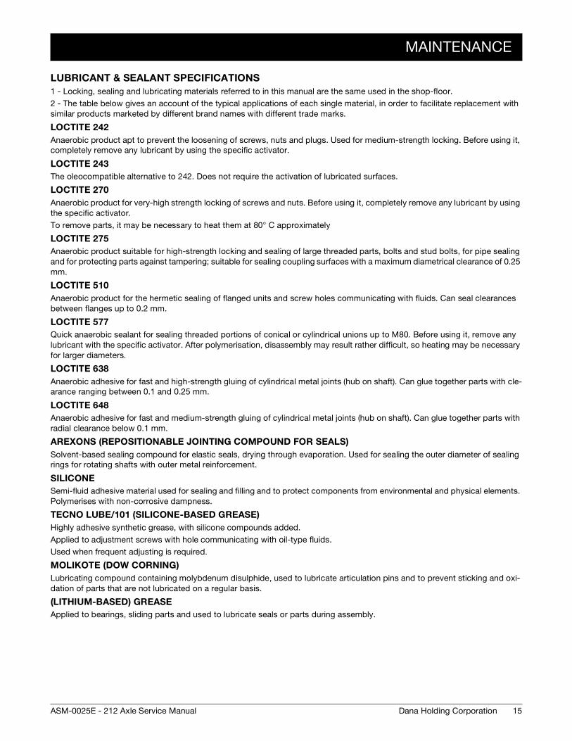
LUBRICANT & SEALANT SPECIFICATIONS
1 - Locking, sealing and lubricating materials referred to in this manual are the same used in the shop-floor.
2 - The table below gives an account of the typical applications of each single material, in order to facilitate replacement with similar products marketed by different brand names with different trade marks.
LOCTITE 242
Anaerobic product apt to prevent the loosening of screws, nuts and plugs. Used for medium-strength locking. Before using it, completely remove any lubricant by using the specific activator.
LOCTITE 243
The oleocompatible alternative to 242. Does not require the activation of lubricated surfaces.
LOCTITE 270
Anaerobic product for very-high strength locking of screws and nuts. Before using it, completely remove any lubricant by using the specific activator.
To remove parts, it may be necessary to heat them at 80° C approximately
LOCTITE 275
Anaerobic product suitable for high-strength locking and sealing of large threaded parts, bolts and stud bolts, for pipe sealing and for protecting parts against tampering; suitable for sealing coupling surfaces with a maximum diametrical clearance of 0.25 mm.
LOCTITE 510
Anaerobic product for the hermetic sealing of flanged units and screw holes communicating with fluids. Can seal clearances between flanges up to 0.2 mm.
LOCTITE 577
Quick anaerobic sealant for sealing threaded portions of conical or cylindrical unions up to M80. Before using it, remove any lubricant with the specific activator. After polymerisation, disassembly may result rather difficult, so heating may be necessary for larger diameters.
LOCTITE 638
Anaerobic adhesive for fast and high-strength gluing of cylindrical metal joints (hub on shaft). Can glue together parts with cle-arance ranging between 0.1 and 0.25 mm.
LOCTITE 648
Anaerobic adhesive for fast and medium-strength gluing of cylindrical metal joints (hub on shaft). Can glue together parts with radial clearance below 0.1 mm.
AREXONS (REPOSITIONABLE JOINTING COMPOUND FOR SEALS)
Solvent-based sealing compound for elastic seals, drying through evaporation. Used for sealing the outer diameter of sealing rings for rotating shafts with outer metal reinforcement.
SILICONE
Semi-fluid adhesive material used for sealing and filling and to protect components from environmental and physical elements. Polymerises with non-corrosive dampness.
TECNO LUBE/101 (SILICONE-BASED GREASE)
Highly adhesive synthetic grease, with silicone compounds added.
Applied to adjustment screws with hole communicating with oil-type fluids.
Used when frequent adjusting is required.
MOLIKOTE (DOW CORNING)
Lubricating compound containing molybdenum disulphide, used to lubricate articulation pins and to prevent sticking and oxi-dation of parts that are not lubricated on a regular basis.
(LITHIUM-BASED) GREASE
Applied to bearings, sliding parts and used to lubricate seals or parts during assembly.

16
MAINTENANCE
Dana Holding Corporation ASM-0025E - 212 Axle Service Manual
17Dana Holding CorporationASM-0025E - 212 Axle Service Manual
SAFETY PRECAUTIONS
1 - During all operations described in this manual, the axle should be fastened onto a trestle, while the other parts mentioned should rest on supporting benches.
2 - When removing one of the arms, an anti-tilting safety trestle should be placed under the other arm.
3 - When working on an arm that is fitted on the machine, make sure that the supporting trestles are correctly po-sitioned and that the machine is locked lengthways.
4 - Do not admit any other person inside the work area; mark off the area, hang warning signs and remove the igni-tion key from the machine.
5 - Use only clean, quality tools; discard all worn, damaged, lowquality or improvised wrenches and tools. Ensure that all torque wrenches have been checked and calibrated.
6 - Always wear gloves and non-slip rubber shoes when performing repair work.
7 - Should you stain a surface with oil, remove marks straight away.
8 - Dispose of all lubricants, seals, rags and solvents once work has been completed. Treat them as special waste and dispose of them according to the relative law provisions obtaining in the country where the axles are being overhauled.
9 - Make sure that only weak solvents are used for cleaning purposes; avoid using turpentine, dilutants and toluol, xylolbased or similar solvents; use light solvents such as Kerosene, mineral spirits or water-based, environment friendly solvents.
10 - For the sake of clarity, the parts that do not normally need to be removed have not been reproduced in some of the diagrams.
11 - For agricultural axles, the terms RIGHT and LEFT refer to the position from operator’s seat. For construcition axle, the terms RIGHT and LEFT refer to the position outside facing the machine (with the input drive facing forward).
12 - After repair work has been completed, accurately touch up any coated part that may have been damaged.
13 - Follow all safety instructions in the Original Equipment Manufacturer (OEM) manual that came with the vehicle.
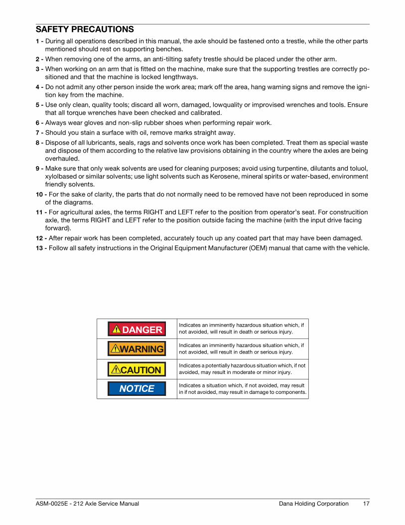
Indicates an imminently hazardous situation which, if not avoided, will result in death or serious injury.
Indicates an imminently hazardous situation which, if not avoided, will result in death or serious injury.
Indicates a potentially hazardous situation which, if not avoided, may result in moderate or minor injury.
Indicates a situation which, if not avoided, may result in if not avoided, may result in damage to components.
DANGER
WARNING
CAUTION
NOTICE

18
MAINTENANCE
Dana Holding Corporation ASM-0025E - 212 Axle Service Manual
19Dana Holding CorporationASM-0025E - 212 Axle Service Manual
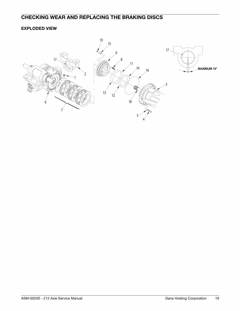
CHECKING WEAR AND REPLACING THE BRAKING DISCS
EXPLODED VIEW
12
3
45
6
7
8
9
10
11
1213
14
15
16
17
18
17
MAXIMUM 10°
20
DISASSEMBLY
Dana Holding Corporation ASM-0025E - 212 Axle Service Manual
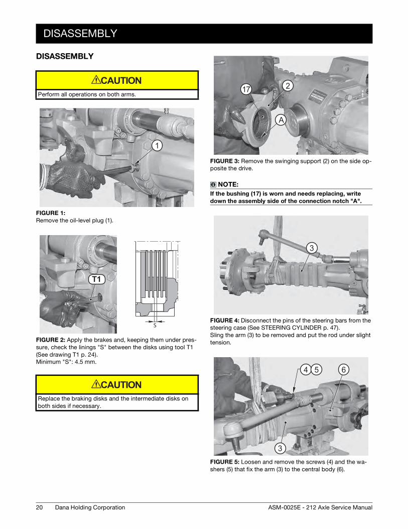
DISASSEMBLY
Perform all operations on both arms.
FIGURE 1:
Remove the oil-level plug (1).
FIGURE 2: Apply the brakes and, keeping them under pres-sure, check the linings "S" between the disks using tool T1 (See drawing T1 p. 24). Minimum "S": 4.5 mm.
Replace the braking disks and the intermediate disks on both sides if necessary.
CAUTION
1
T1
S
T1
CAUTION
FIGURE 3: Remove the swinging support (2) on the side op-posite the drive.
NOTE:
If the bushing (17) is worn and needs replacing, write
down the assembly side of the connection notch "A".
FIGURE 4: Disconnect the pins of the steering bars from the steering case (See STEERING CYLINDER p. 47). Sling the arm (3) to be removed and put the rod under slight tension.
FIGURE 5: Loosen and remove the screws (4) and the wa-shers (5) that fix the arm (3) to the central body (6).
A
17 2
A
3
3
64 5
DISASSEMBLY
21Dana Holding CorporationASM-0025E - 212 Axle Service Manual
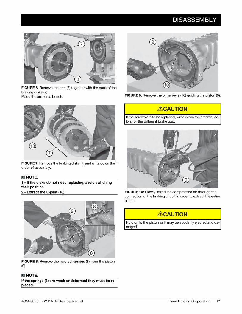
FIGURE 6: Remove the arm (3) together with the pack of the braking disks (7). Place the arm on a bench.
FIGURE 7: Remove the braking disks (7) and write down their order of assembly.
NOTE:
1 - If the disks do not need replacing, avoid switching
their position.
2 - Extract the u-joint (18).
FIGURE 8: Remove the reversal springs (8) from the piston (9).
NOTE:
If the springs (8) are weak or deformed they must be re-
placed.
3
7
187
8
8
9
FIGURE 9: Remove the pin screws (10) guiding the piston (9).
If the screws are to be replaced, write down the different co-lors for the different brake gap.
FIGURE 10: Slowly introduce compressed air through the connection of the braking circuit in order to extract the entire piston.
Hold on to the piston as it may be suddenly ejected and da-maged.
10
9
CAUTION
9
CAUTION
22
ASSEMBLY
Dana Holding Corporation ASM-0025E - 212 Axle Service Manual
ASSEMBLY
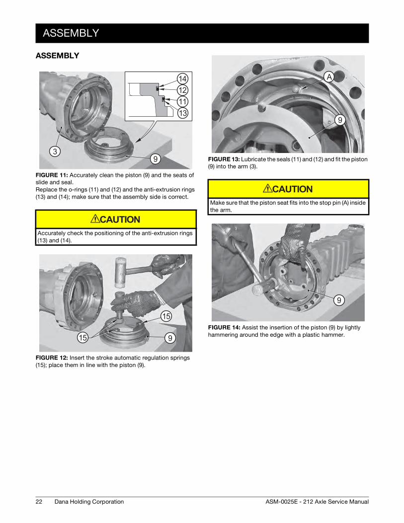
FIGURE 11: Accurately clean the piston (9) and the seats of slide and seal. Replace the o-rings (11) and (12) and the anti-extrusion rings (13) and (14); make sure that the assembly side is correct.
Accurately check the positioning of the anti-extrusion rings (13) and (14).
FIGURE 12: Insert the stroke automatic regulation springs (15); place them in line with the piston (9).
93
14
13
1211
CAUTION
9
15
15
FIGURE 13: Lubricate the seals (11) and (12) and fit the piston (9) into the arm (3).
Make sure that the piston seat fits into the stop pin (A) inside the arm.
FIGURE 14: Assist the insertion of the piston (9) by lightly hammering around the edge with a plastic hammer.
AA
9
CAUTION
9
ASSEMBLY
23Dana Holding CorporationASM-0025E - 212 Axle Service Manual
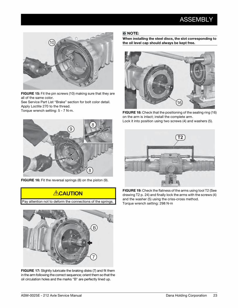
FIGURE 15: Fit the pin screws (10) making sure that they are all of the same color. See Service Part List “Brake” section for bolt color detail.Apply Loctite 270 to the thread. Torque wrench setting: 5 - 7 N·m.
FIGURE 16: Fit the reversal springs (8) on the piston (9).
Pay attention not to deform the connections of the springs.
FIGURE 17: Slightly lubricate the braking disks (7) and fit them in the arm following the correct sequence; orient them so that the oil circulation holes and the marks "B" are perfectly lined up.
10
8
8
9
CAUTION
B
7
B
NOTE:
When installing the steel discs, the slot corresponding to
the oil level cap should always be kept free.
FIGURE 18: Check that the positioning of the sealing ring (16) on the arm is intact; install the complete arm. Lock it into position using two screws (4) and washers (5).
FIGURE 19: Check the flatness of the arms using tool T2 (See drawing T2 p. 24) and finally lock the arms with the screws (4) and the washer (5) using the criss-cross method. Torque wrench setting: 298 N·m
16
T2T2
24
SPECIAL TOOLS
Dana Holding Corporation ASM-0025E - 212 Axle Service Manual
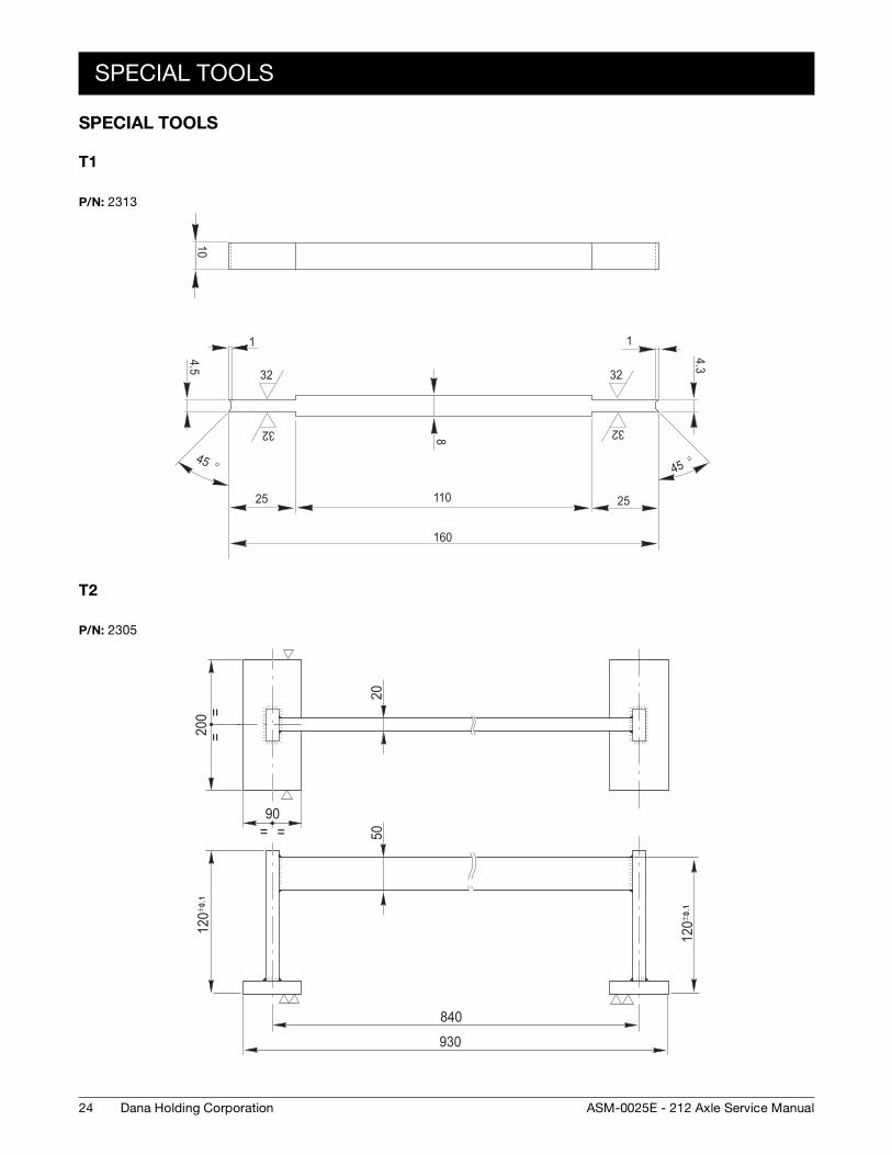
SPECIAL TOOLS
T1
T2
P/N: 2313
32
32
32
32
104.5
25
45 °
110
160
25
1
4.3
45 °8
1
P/N: 2305
200 =
=
90= =
2050
120± 0
.1
840
930
120± 0
.1
25Dana Holding CorporationASM-0025E - 212 Axle Service Manual
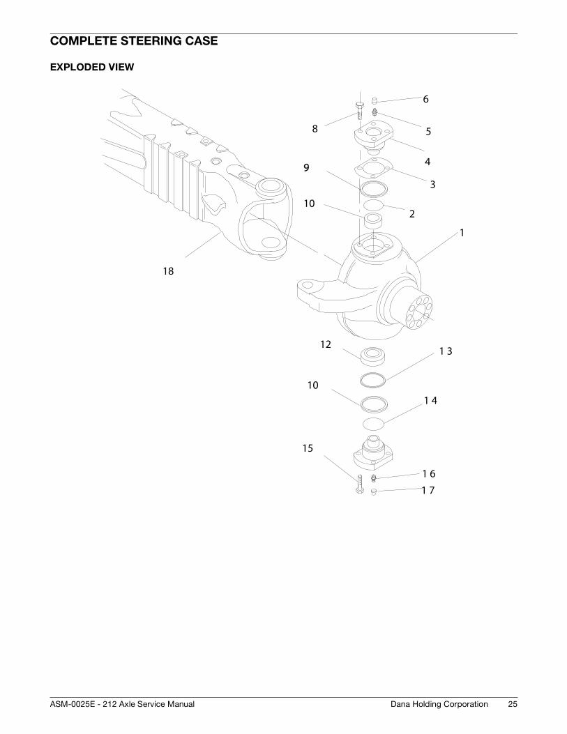
COMPLETE STEERING CASE
EXPLODED VIEW
2
4
6
8
10
1
3
5
99
121 3
101 4
15
1 61 7
18
26
DISASSEMBLY
Dana Holding Corporation ASM-0025E - 212 Axle Service Manual
DISASSEMBLY
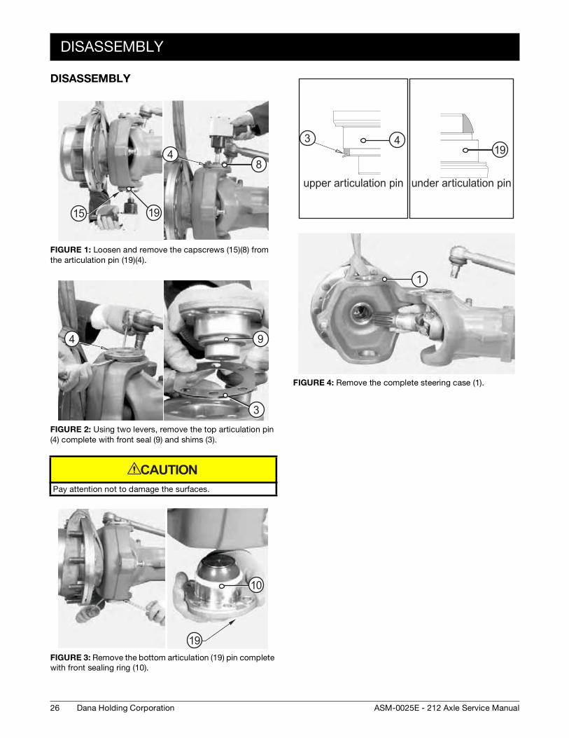
FIGURE 1: Loosen and remove the capscrews (15)(8) from the articulation pin (19)(4).
FIGURE 2: Using two levers, remove the top articulation pin (4) complete with front seal (9) and shims (3).
Pay attention not to damage the surfaces.
FIGURE 3: Remove the bottom articulation (19) pin complete with front sealing ring (10).
15 19
48
4 9
3
CAUTION
19
10
FIGURE 4: Remove the complete steering case (1).
4319
1
ASSEMBLY
27Dana Holding CorporationASM-0025E - 212 Axle Service Manual
ASSEMBLY
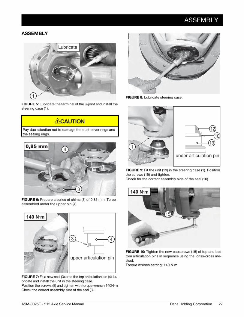
FIGURE 5: Lubricate the terminal of the u-joint and install the steering case (1).
Pay due attention not to damage the dust cover rings and the sealing rings.
FIGURE 6: Prepare a series of shims (3) of 0,85 mm. To be assembled under the upper pin (4).
FIGURE 7: Fit a new seal (3) onto the top articulation pin (4). Lu-bricate and install the unit in the steering case. Position the screws (8) and tighten with torque wrench 140N·m.Check the correct assembly side of the seal (3).
1
CAUTION
4
3
140 N·m
3 4
FIGURE 8: Lubricate steering case.
FIGURE 9: Fit the unit (19) in the steering case (1). Position the screws (15) and tighten.Check for the correct assembly side of the seal (10).
FIGURE 10: Tighten the new capscrews (15) of top and bot-tom articulation pins in sequence using the criss-cross me-thod.Torque wrench setting: 140 N·m
1210
191
140 N·m
15
28
ASSEMBLY
Dana Holding Corporation ASM-0025E - 212 Axle Service Manual
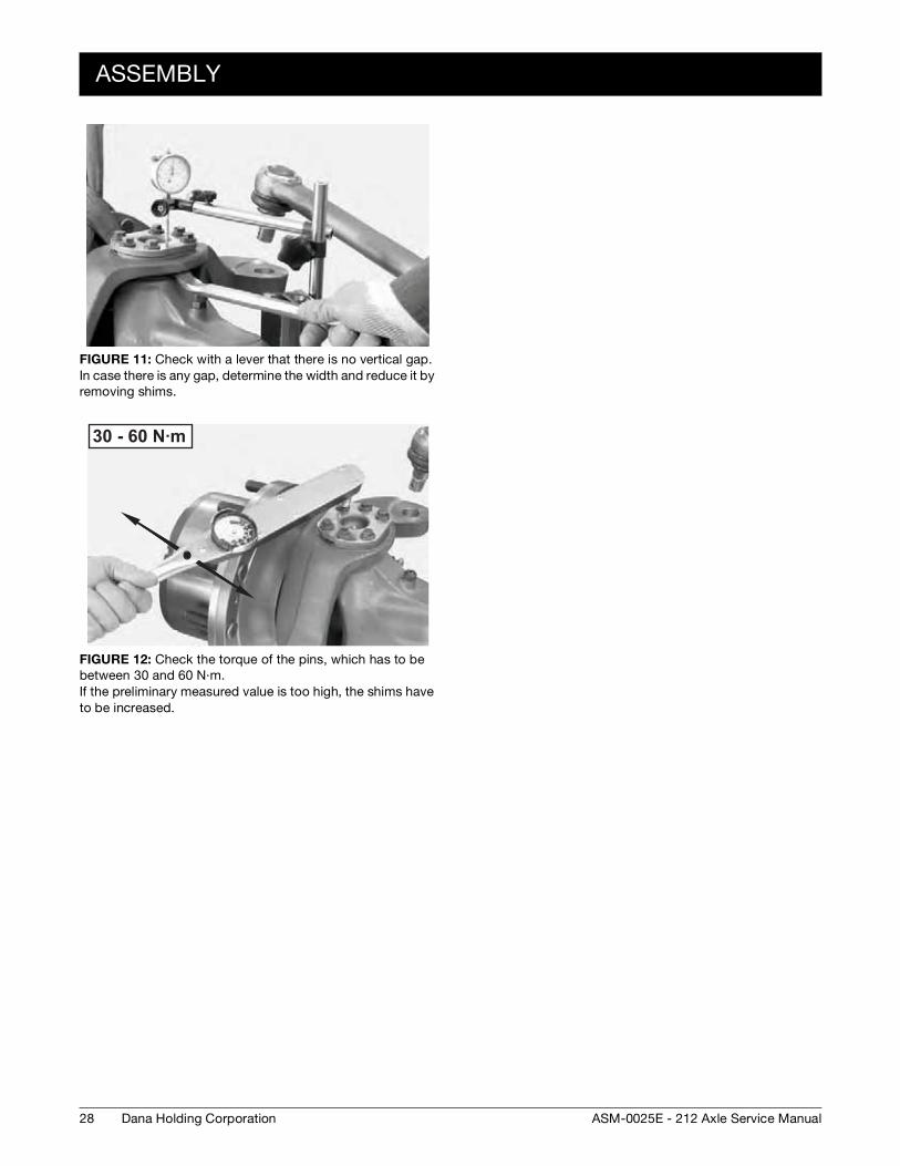
FIGURE 11: Check with a lever that there is no vertical gap.In case there is any gap, determine the width and reduce it by removing shims.
FIGURE 12: Check the torque of the pins, which has to be between 30 and 60 N·m. If the preliminary measured value is too high, the shims have to be increased.
30 - 60 N·m
29Dana Holding CorporationASM-0025E - 212 Axle Service Manual
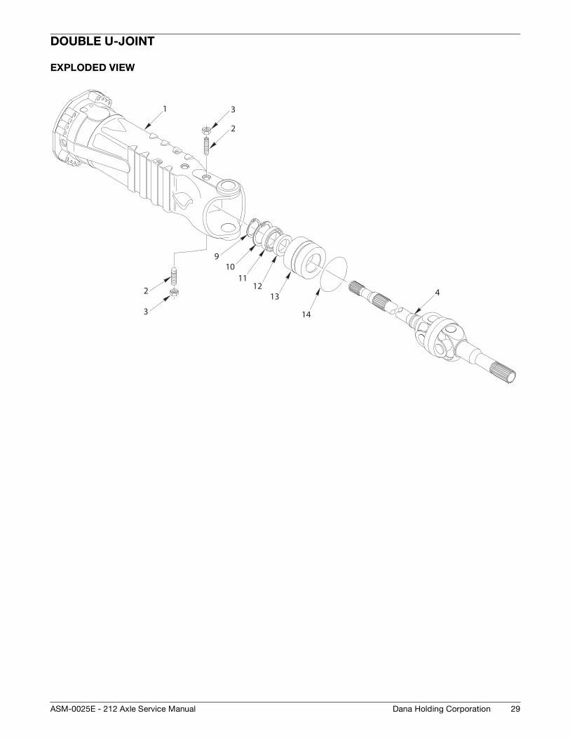
DOUBLE U-JOINT
EXPLODED VIEW
1
2
3
4
10
13
14
9
3
211
12
30
DISASSEMBLY
Dana Holding Corporation ASM-0025E - 212 Axle Service Manual
DISASSEMBLY
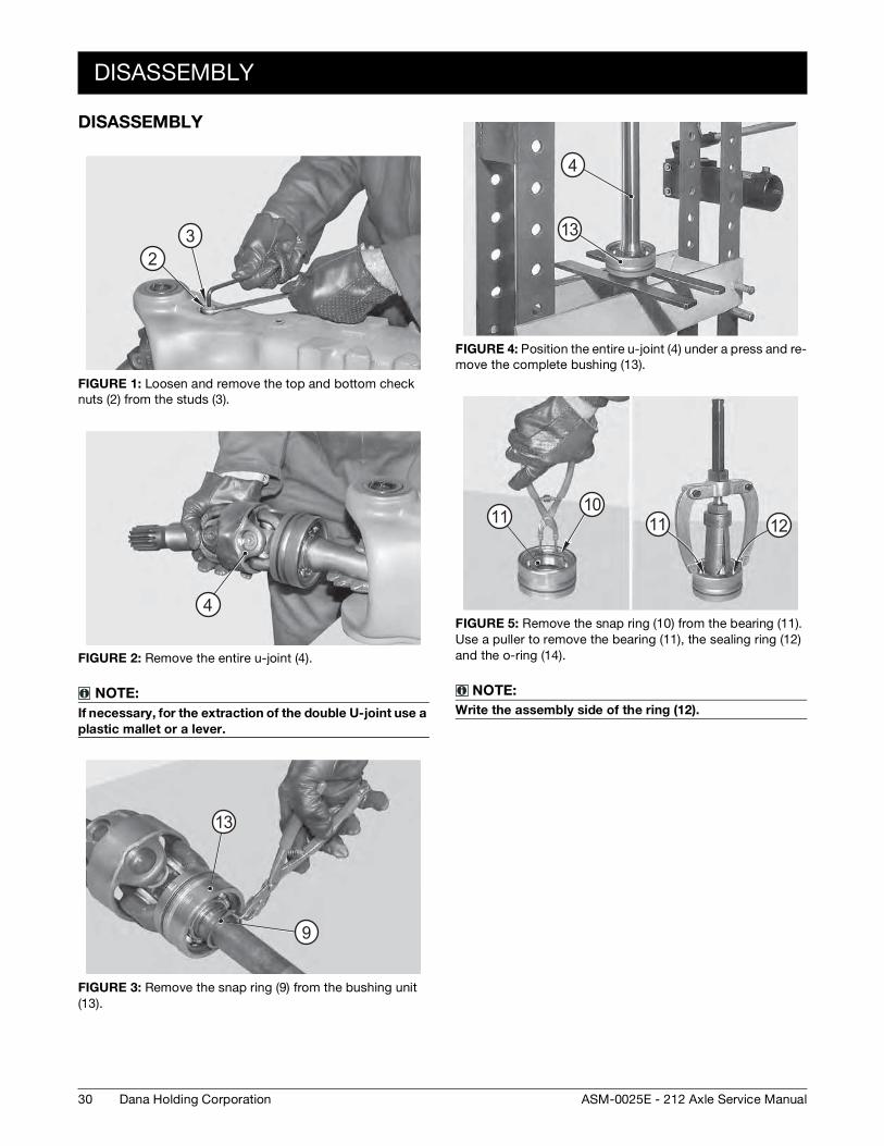
FIGURE 1: Loosen and remove the top and bottom check nuts (2) from the studs (3).
FIGURE 2: Remove the entire u-joint (4).
NOTE:
If necessary, for the extraction of the double U-joint use a
plastic mallet or a lever.
FIGURE 3: Remove the snap ring (9) from the bushing unit (13).
32
4
13
9
FIGURE 4: Position the entire u-joint (4) under a press and re-move the complete bushing (13).
FIGURE 5: Remove the snap ring (10) from the bearing (11). Use a puller to remove the bearing (11), the sealing ring (12) and the o-ring (14).
NOTE:
Write the assembly side of the ring (12).
13
4
1110
11 12
ASSEMBLY
31Dana Holding CorporationASM-0025E - 212 Axle Service Manual
ASSEMBLY
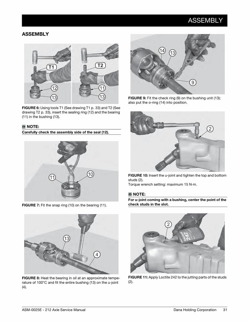
FIGURE 6: Using tools T1 (See drawing T1 p. 33) and T2 (See drawing T2 p. 33), insert the sealing ring (12) and the bearing (11) in the bushing (13).
NOTE:
Carefully check the assembly side of the seal (12).
FIGURE 7: Fit the snap ring (10) on the bearing (11).
FIGURE 8: Heat the bearing in oil at an approximate tempe-rature of 100°C and fit the entire bushing (13) on the u-joint (4).
T5 T6T1 T2
12
13
11
13
11 10
13
4
FIGURE 9: Fit the check ring (9) on the bushing unit (13); also put the o-ring (14) into position.
FIGURE 10: Insert the u-joint and tighten the top and bottom studs (2). Torque wrench setting: maximum 15 N·m.
NOTE:
For u-joint coming with a bushing, center the point of the
check studs in the slot.
FIGURE 11: Apply Loctite 242 to the jutting parts of the studs (2).
1314
9
2
2
32
ASSEMBLY
Dana Holding Corporation ASM-0025E - 212 Axle Service Manual
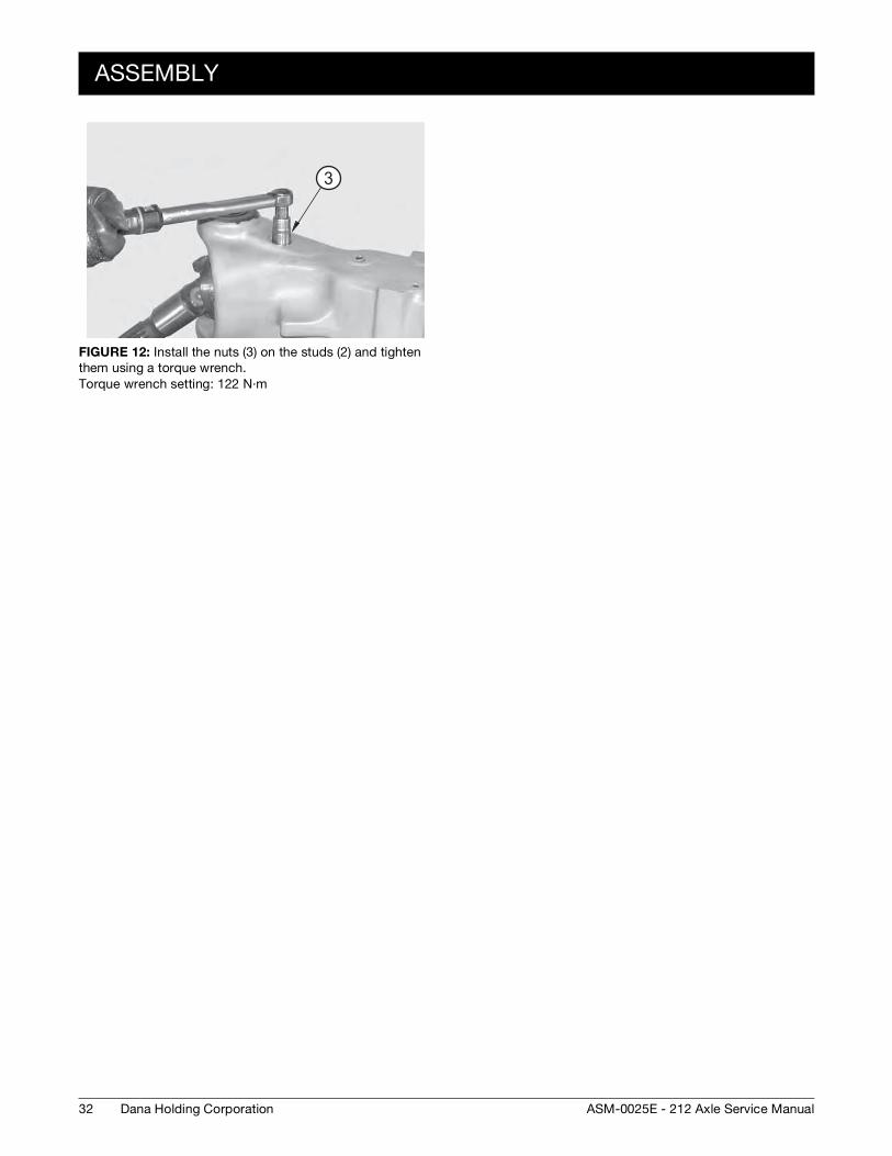
FIGURE 12: Install the nuts (3) on the studs (2) and tighten them using a torque wrench. Torque wrench setting: 122 N·m
3
SPECIAL TOOLS
33Dana Holding CorporationASM-0025E - 212 Axle Service Manual
SPECIAL TOOLS
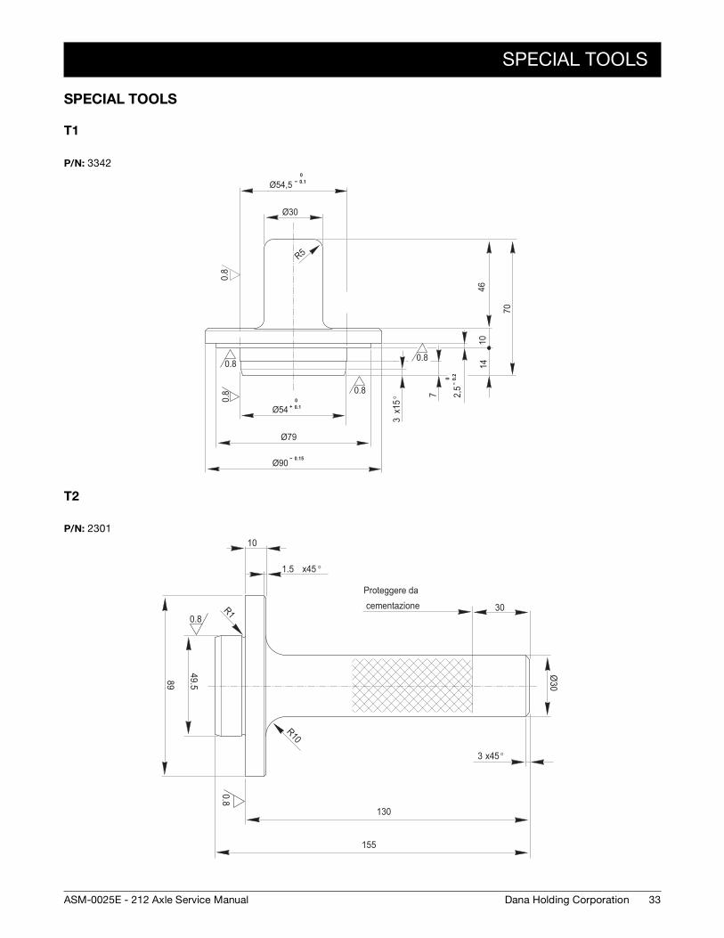
T1
T2
P/N: 3342
0.8
0.8
0.8
0.80.8
R5
0+ 0.1Ø54
Ø79
-- 0.15Ø90
7
x15°
3
0--
0.2
2,5
1410
70
46
Ø30
Ø54,50
-- 0.1
P/N: 2301
0.8
0.8
Ø30
49.58910
130
155
Proteggere da cementazione 30R1
x45°3
x45 °1.5
R10

34
SPECIAL TOOLS
Dana Holding Corporation ASM-0025E - 212 Axle Service Manual
35Dana Holding CorporationASM-0025E - 212 Axle Service Manual
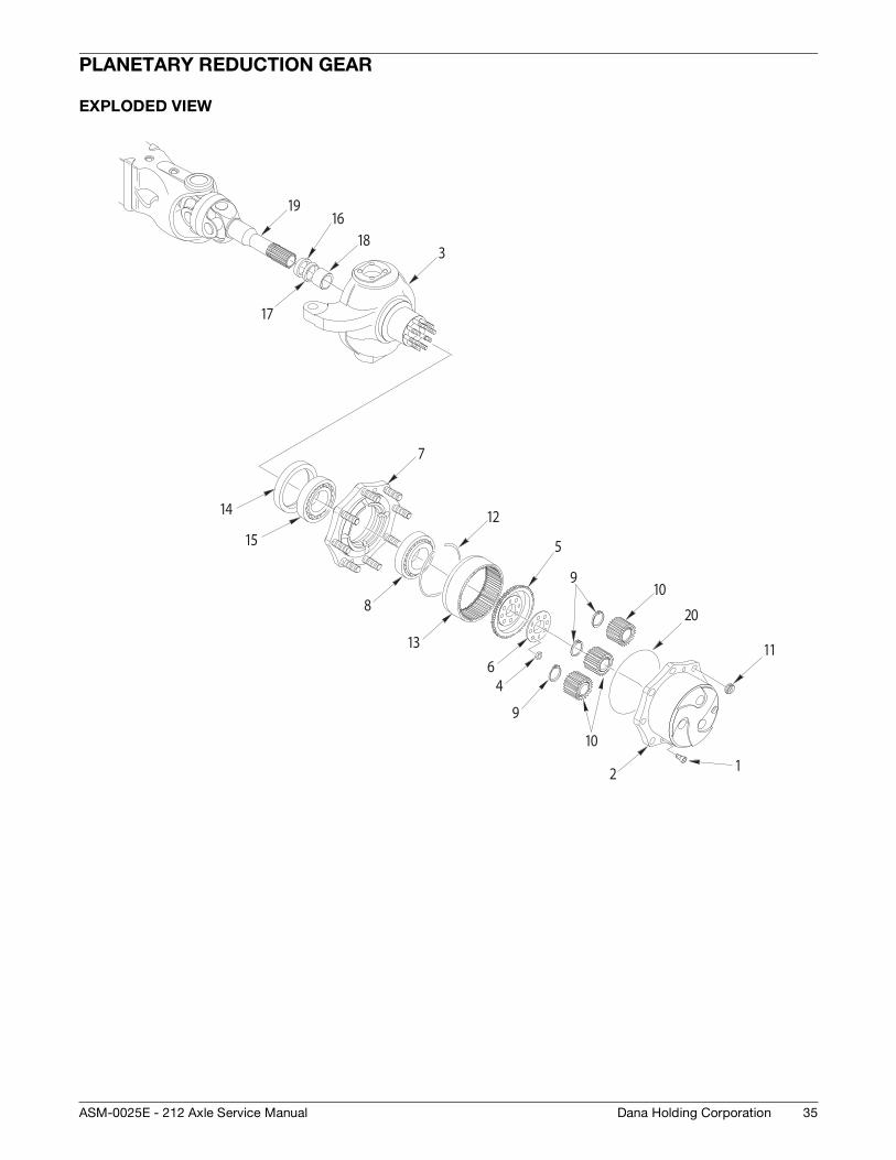
PLANETARY REDUCTION GEAR
EXPLODED VIEW
3
16
17
18
19
12
4
5
6
8
910
11
12
13
20
9
10
7
14
15
36
DISASSEMBLY
Dana Holding Corporation ASM-0025E - 212 Axle Service Manual
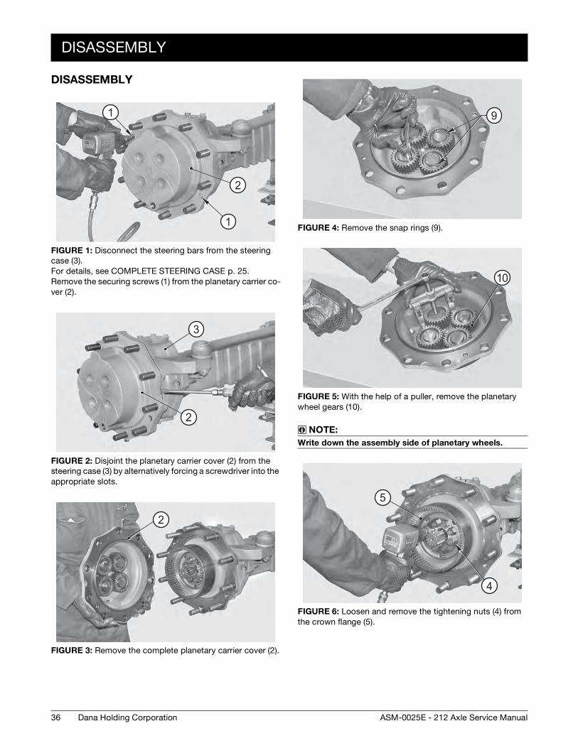
DISASSEMBLY
FIGURE 1: Disconnect the steering bars from the steering case (3). For details, see COMPLETE STEERING CASE p. 25. Remove the securing screws (1) from the planetary carrier co-ver (2).
FIGURE 2: Disjoint the planetary carrier cover (2) from the steering case (3) by alternatively forcing a screwdriver into the appropriate slots.
FIGURE 3: Remove the complete planetary carrier cover (2).
1
1
2
2
3
2
FIGURE 4: Remove the snap rings (9).
FIGURE 5: With the help of a puller, remove the planetary wheel gears (10).
NOTE:
Write down the assembly side of planetary wheels.
FIGURE 6: Loosen and remove the tightening nuts (4) from the crown flange (5).
9
10
5
4
DISASSEMBLY
37Dana Holding CorporationASM-0025E - 212 Axle Service Manual
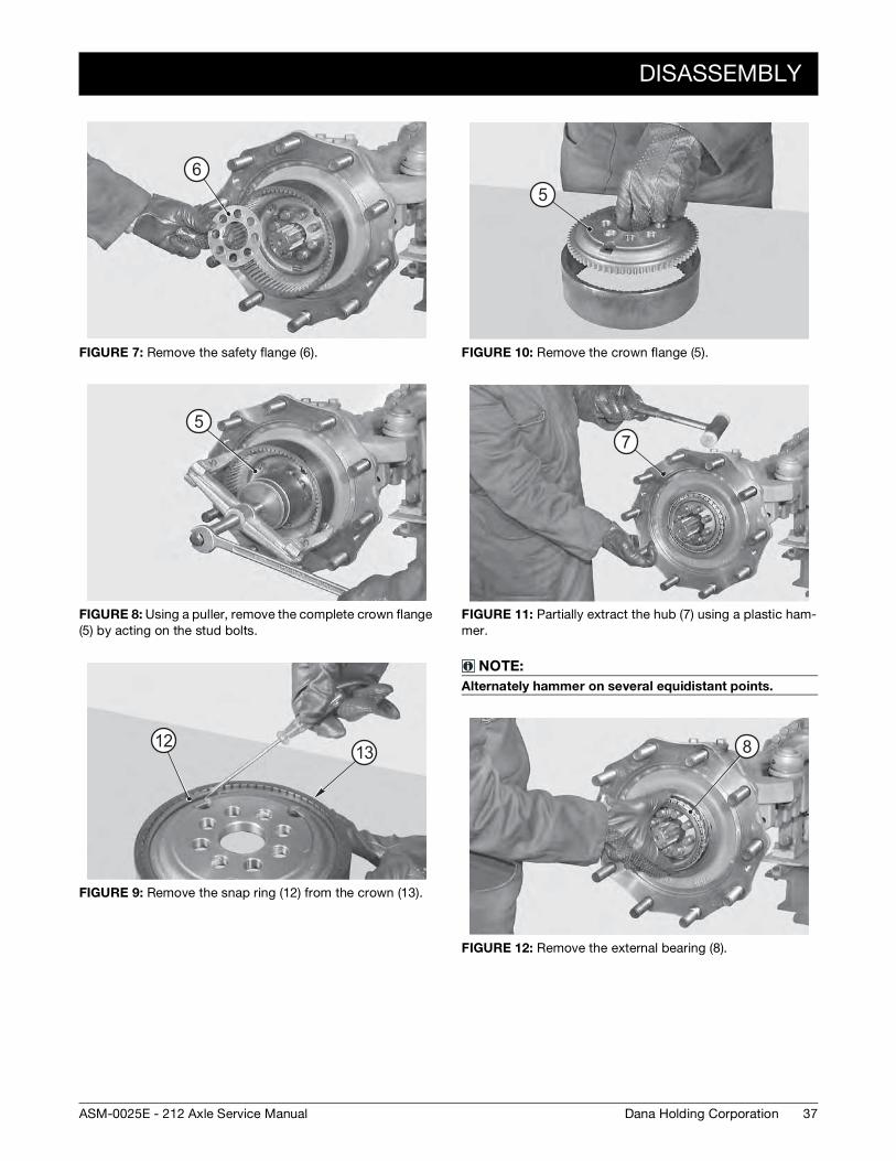
FIGURE 7: Remove the safety flange (6).
FIGURE 8: Using a puller, remove the complete crown flange (5) by acting on the stud bolts.
FIGURE 9: Remove the snap ring (12) from the crown (13).
6
5
1312
FIGURE 10: Remove the crown flange (5).
FIGURE 11: Partially extract the hub (7) using a plastic ham-mer.
NOTE:
Alternately hammer on several equidistant points.
FIGURE 12: Remove the external bearing (8).
5
7
8
38
DISASSEMBLY
Dana Holding Corporation ASM-0025E - 212 Axle Service Manual
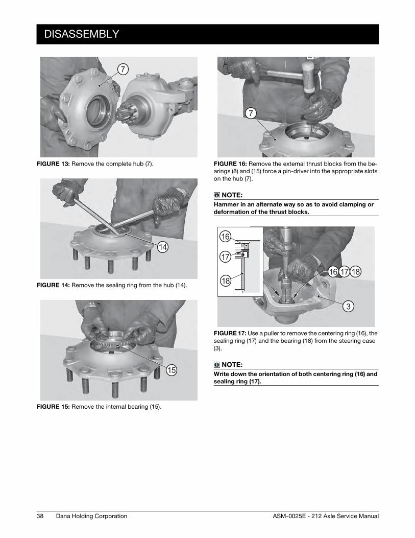
FIGURE 13: Remove the complete hub (7).
FIGURE 14: Remove the sealing ring from the hub (14).
FIGURE 15: Remove the internal bearing (15).
7
14
15
FIGURE 16: Remove the external thrust blocks from the be-arings (8) and (15) force a pin-driver into the appropriate slots on the hub (7).
NOTE:
Hammer in an alternate way so as to avoid clamping or
deformation of the thrust blocks.
FIGURE 17: Use a puller to remove the centering ring (16), the sealing ring (17) and the bearing (18) from the steering case (3).
NOTE:
Write down the orientation of both centering ring (16) and
sealing ring (17).
7
16 17 18
16
17
18
3
DISASSEMBLY
39Dana Holding CorporationASM-0025E - 212 Axle Service Manual
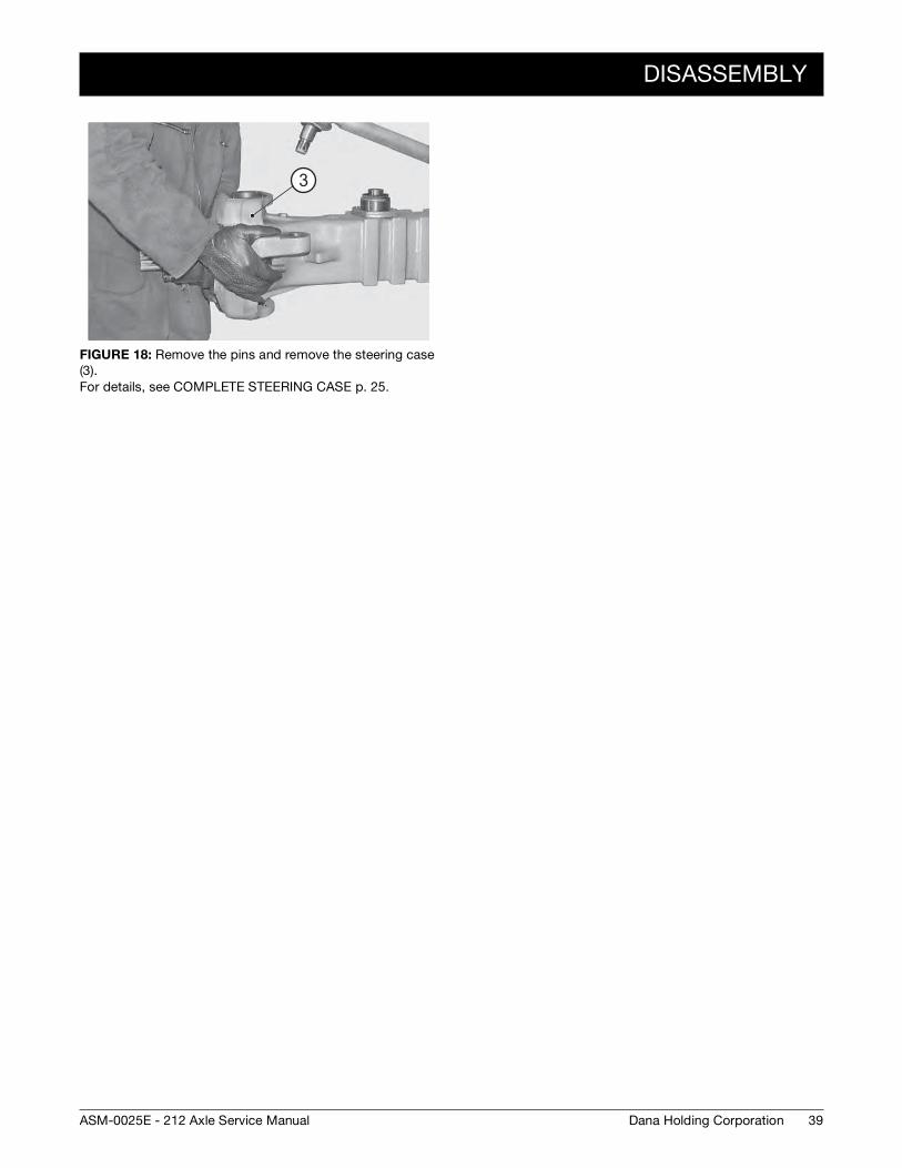
FIGURE 18: Remove the pins and remove the steering case (3). For details, see COMPLETE STEERING CASE p. 25.
3
40
ASSEMBLY
Dana Holding Corporation ASM-0025E - 212 Axle Service Manual
ASSEMBLY
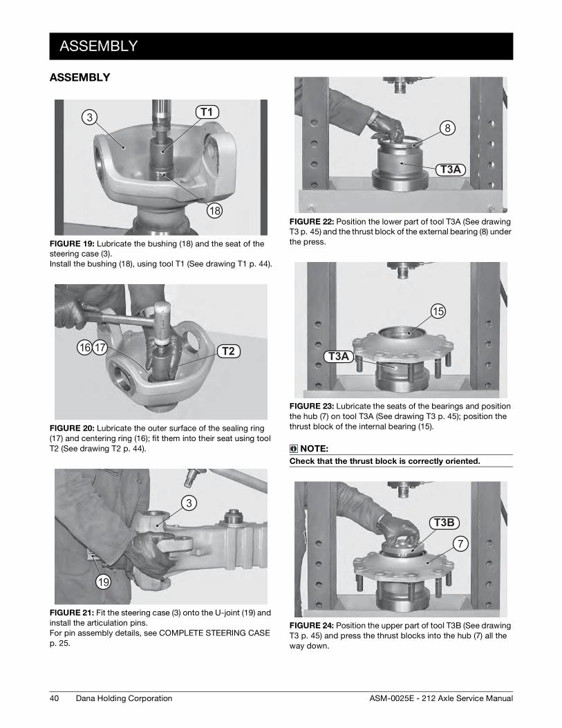
FIGURE 19: Lubricate the bushing (18) and the seat of the steering case (3). Install the bushing (18), using tool T1 (See drawing T1 p. 44).
FIGURE 20: Lubricate the outer surface of the sealing ring (17) and centering ring (16); fit them into their seat using tool T2 (See drawing T2 p. 44).
FIGURE 21: Fit the steering case (3) onto the U-joint (19) and install the articulation pins. For pin assembly details, see COMPLETE STEERING CASE p. 25.
T 7T1
18
3
T8T216 17
19
3
FIGURE 22: Position the lower part of tool T3A (See drawing T3 p. 45) and the thrust block of the external bearing (8) under the press.
FIGURE 23: Lubricate the seats of the bearings and position the hub (7) on tool T3A (See drawing T3 p. 45); position the thrust block of the internal bearing (15).
NOTE:
Check that the thrust block is correctly oriented.
FIGURE 24: Position the upper part of tool T3B (See drawing T3 p. 45) and press the thrust blocks into the hub (7) all the way down.
T9 AT3A
8
T9 AT3A
15
T9 BT3B
7
ASSEMBLY
41Dana Holding CorporationASM-0025E - 212 Axle Service Manual
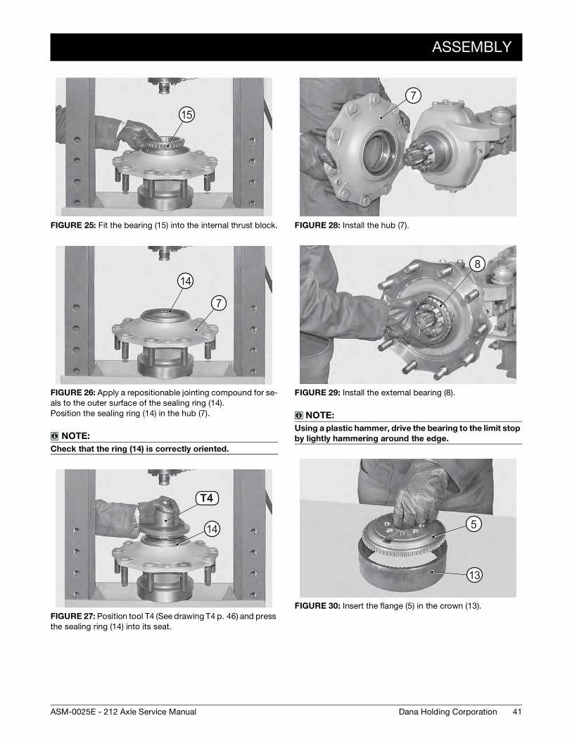
FIGURE 25: Fit the bearing (15) into the internal thrust block.
FIGURE 26: Apply a repositionable jointing compound for se-als to the outer surface of the sealing ring (14). Position the sealing ring (14) in the hub (7).
NOTE:
Check that the ring (14) is correctly oriented.
FIGURE 27: Position tool T4 (See drawing T4 p. 46) and press the sealing ring (14) into its seat.
15
14
7
T1 0T4
14
FIGURE 28: Install the hub (7).
FIGURE 29: Install the external bearing (8).
NOTE:
Using a plastic hammer, drive the bearing to the limit stop
by lightly hammering around the edge.
FIGURE 30: Insert the flange (5) in the crown (13).
7
8
13
5
42
ASSEMBLY
Dana Holding Corporation ASM-0025E - 212 Axle Service Manual
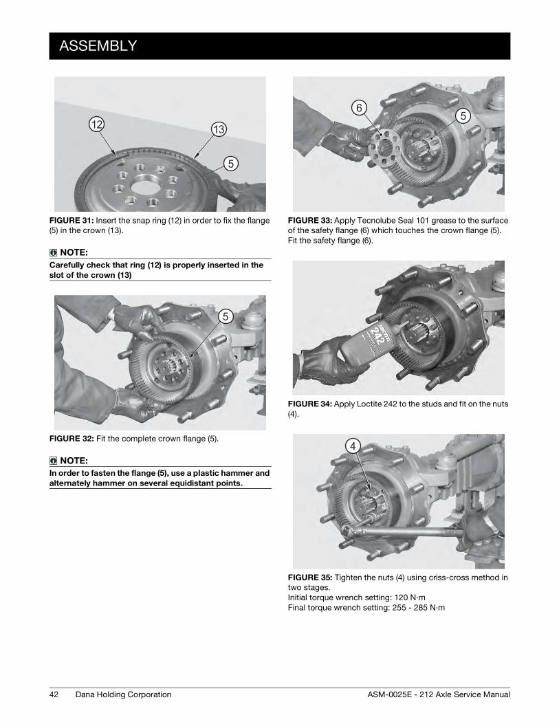
FIGURE 31: Insert the snap ring (12) in order to fix the flange (5) in the crown (13).
NOTE:
Carefully check that ring (12) is properly inserted in the
slot of the crown (13)
FIGURE 32: Fit the complete crown flange (5).
NOTE:
In order to fasten the flange (5), use a plastic hammer and
alternately hammer on several equidistant points.
12 13
5
5
FIGURE 33: Apply Tecnolube Seal 101 grease to the surface of the safety flange (6) which touches the crown flange (5). Fit the safety flange (6).
FIGURE 34: Apply Loctite 242 to the studs and fit on the nuts (4).
FIGURE 35: Tighten the nuts (4) using criss-cross method in two stages. Initial torque wrench setting: 120 N·m Final torque wrench setting: 255 - 285 N·m
56
4
ASSEMBLY
43Dana Holding CorporationASM-0025E - 212 Axle Service Manual
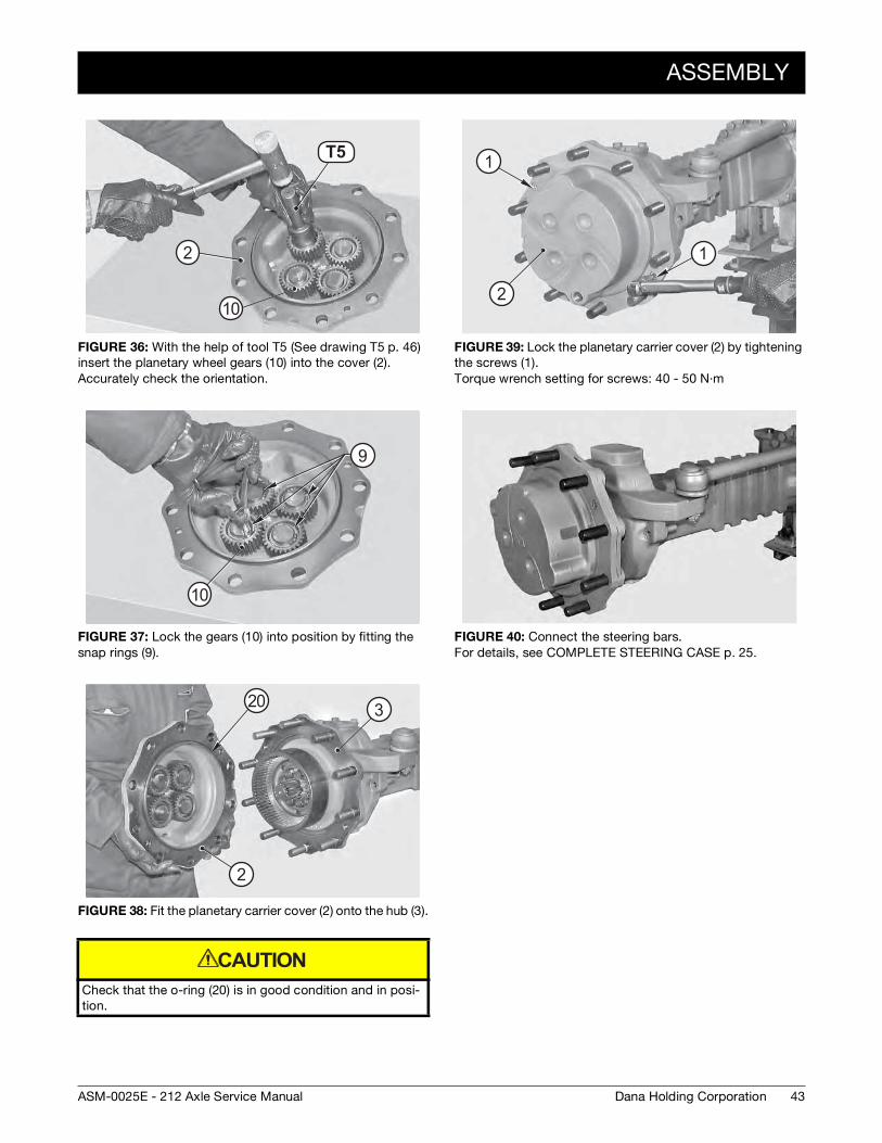
FIGURE 36: With the help of tool T5 (See drawing T5 p. 46) insert the planetary wheel gears (10) into the cover (2). Accurately check the orientation.
FIGURE 37: Lock the gears (10) into position by fitting the snap rings (9).
FIGURE 38: Fit the planetary carrier cover (2) onto the hub (3).
Check that the o-ring (20) is in good condition and in posi-tion.
T1 1T5
10
2
10
9
3
2
20
CAUTION
FIGURE 39: Lock the planetary carrier cover (2) by tightening the screws (1). Torque wrench setting for screws: 40 - 50 N·m
FIGURE 40: Connect the steering bars. For details, see COMPLETE STEERING CASE p. 25.
2
1
1
44
SPECIAL TOOLS
Dana Holding Corporation ASM-0025E - 212 Axle Service Manual
SPECIAL TOOLS
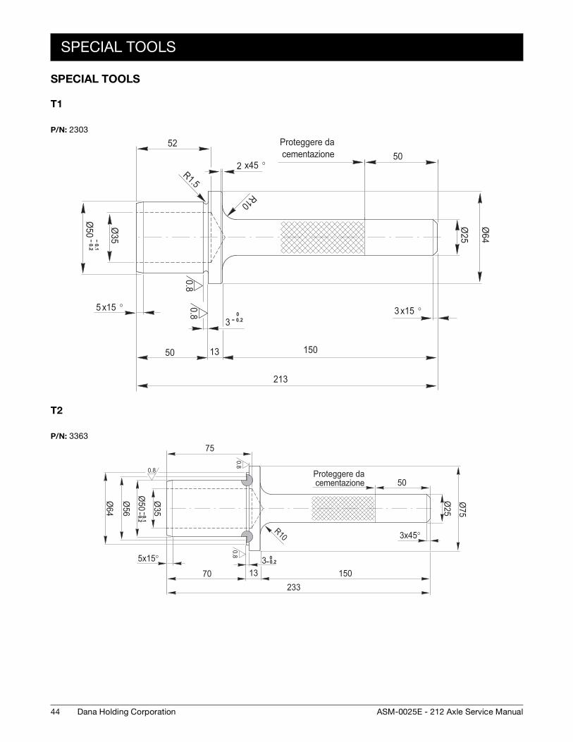
T1
T2
P/N: 2303
0.80.8
Ø35-- 0.1
-- 0.2Ø
50 Ø25
Ø64
50
x15 °30-- 0.23
1350 150
213
52
x15 °5
R1.5
R10
Proteggere da cementazione
x45 °2
P/N: 3363
0.80.8
0.8
Ø35-- 0.1
-- 0.2Ø
50Ø56
Ø64
x15°5
70 13 150233
0-- 0.23
75
50
Ø25
Ø75
x45°3R10
Proteggere da cementazione
SPECIAL TOOLS
45Dana Holding CorporationASM-0025E - 212 Axle Service Manual
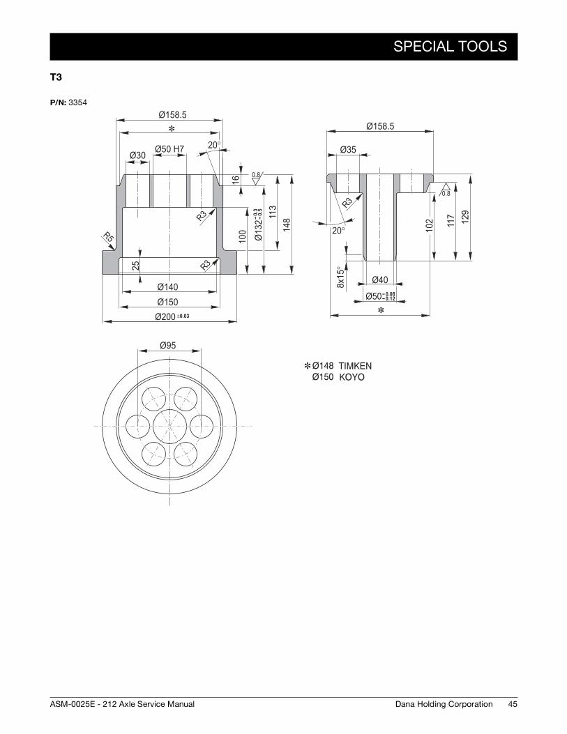
T3
P/N: 3354
0.8
0.8R3
Ø158.5
Ø50 H7Ø30
20°
Ø140Ø150Ø200 ±0.03
100
-- 0.
3--
0.5
Ø13
2
16
113
148
Ø158.5
Ø35
129
117
102
20°
Ø40-- 0.08-- 0.12Ø50
R3
Ø95
25
R3
R5
8x15
°
46
SPECIAL TOOLS
Dana Holding Corporation ASM-0025E - 212 Axle Service Manual
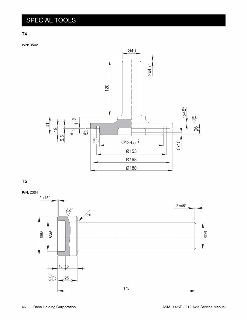
T4
T5
P/N: 3502
0.8 0.8
0.8
0.8
120
Ø4041
195.
5
-- 0.
2--
0.3
1
0-- 0.1Ø139.5
Ø153
Ø168
Ø180
x45°
1
26
x15°
5
x45°
2
P/N: 2304
0.8
0.8
175
25
10 15
Ø39
Ø50
x15°2
x45°2
R3
Ø35
47Dana Holding CorporationASM-0025E - 212 Axle Service Manual
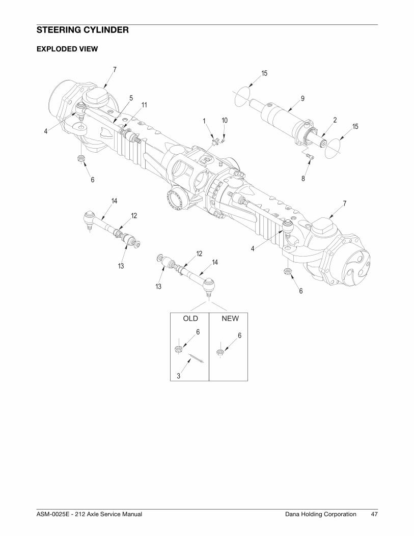
STEERING CYLINDER
EXPLODED VIEW
1 24
5
6
7
8
9
10
12
13
14
15
15
613
12
7
4
14
11
6
3
OLD
6
NEW
48
OPTICAL SENSOR AND MAGNETIC SENSOR
Dana Holding Corporation ASM-0025E - 212 Axle Service Manual
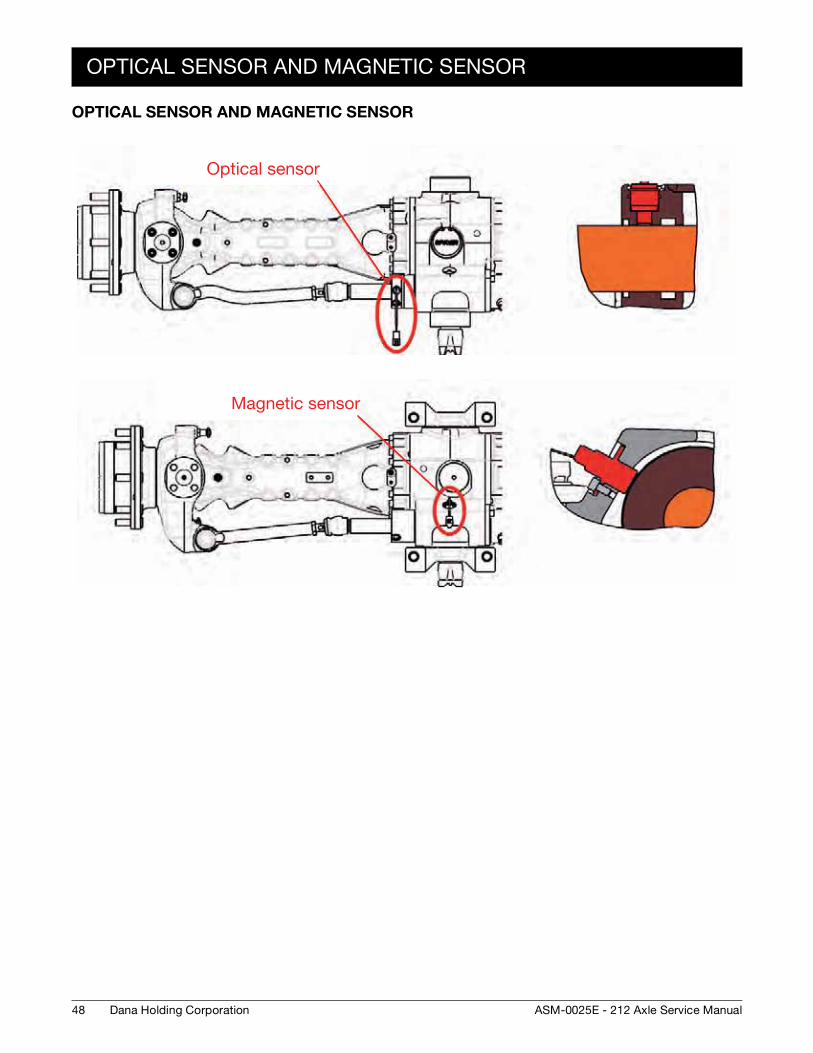
OPTICAL SENSOR AND MAGNETIC SENSOR
Optical sensor
Magnetic sensor
DISASSEMBLY
49Dana Holding CorporationASM-0025E - 212 Axle Service Manual
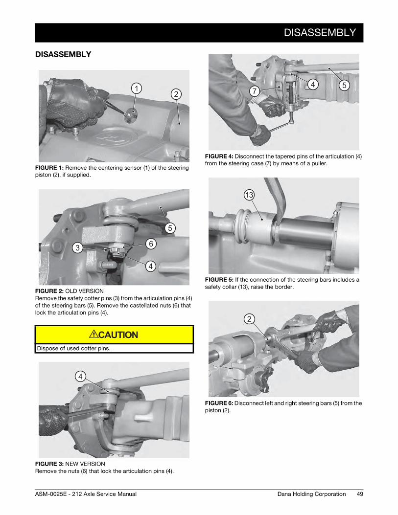
DISASSEMBLY
FIGURE 1: Remove the centering sensor (1) of the steering piston (2), if supplied.
FIGURE 2: OLD VERSIONRemove the safety cotter pins (3) from the articulation pins (4) of the steering bars (5). Remove the castellated nuts (6) that lock the articulation pins (4).
Dispose of used cotter pins.
FIGURE 3: NEW VERSIONRemove the nuts (6) that lock the articulation pins (4).
12
5
6
4
3
CAUTION
4
FIGURE 4: Disconnect the tapered pins of the articulation (4) from the steering case (7) by means of a puller.
FIGURE 5: If the connection of the steering bars includes a safety collar (13), raise the border.
FIGURE 6: Disconnect left and right steering bars (5) from the piston (2).
547
13
2
50
DISASSEMBLY
Dana Holding Corporation ASM-0025E - 212 Axle Service Manual
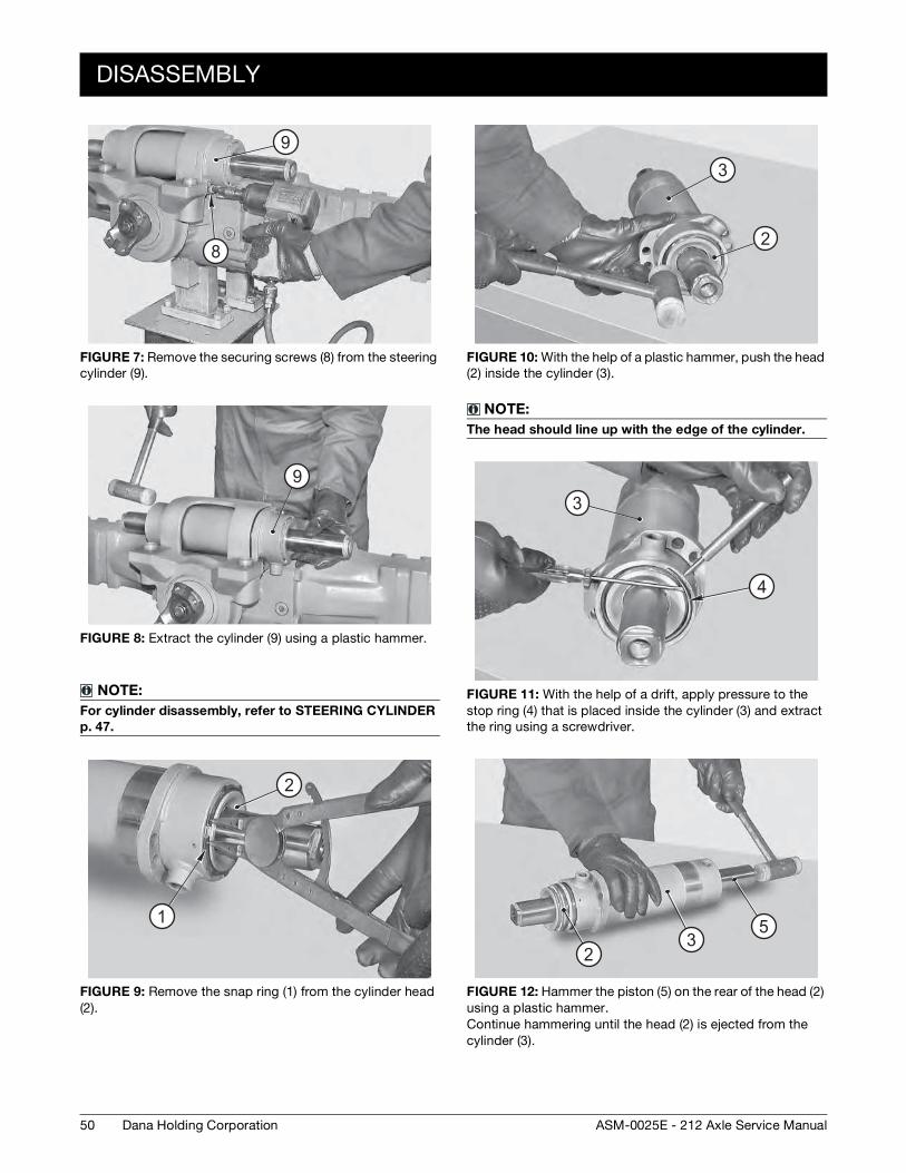
FIGURE 7: Remove the securing screws (8) from the steering cylinder (9).
FIGURE 8: Extract the cylinder (9) using a plastic hammer.
NOTE:
For cylinder disassembly, refer to STEERING CYLINDER
p. 47.
FIGURE 9: Remove the snap ring (1) from the cylinder head (2).
9
8
9
2
1
FIGURE 10: With the help of a plastic hammer, push the head (2) inside the cylinder (3).
NOTE:
The head should line up with the edge of the cylinder.
FIGURE 11: With the help of a drift, apply pressure to the stop ring (4) that is placed inside the cylinder (3) and extract the ring using a screwdriver.
FIGURE 12: Hammer the piston (5) on the rear of the head (2) using a plastic hammer. Continue hammering until the head (2) is ejected from the cylinder (3).
3
2
3
4
53
2
DISASSEMBLY
51Dana Holding CorporationASM-0025E - 212 Axle Service Manual
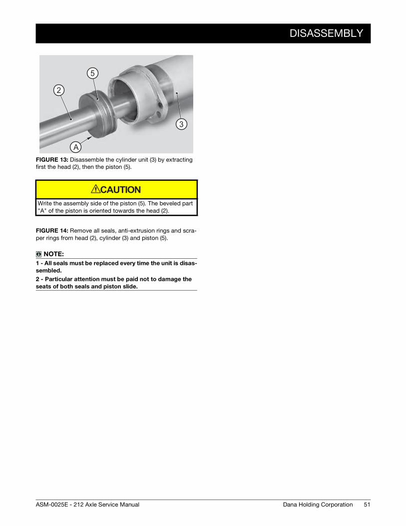
FIGURE 13: Disassemble the cylinder unit (3) by extracting first the head (2), then the piston (5).
Write the assembly side of the piston (5). The beveled part "A" of the piston is oriented towards the head (2).
FIGURE 14: Remove all seals, anti-extrusion rings and scra-per rings from head (2), cylinder (3) and piston (5).
NOTE:
1 - All seals must be replaced every time the unit is disas-
sembled.
2 - Particular attention must be paid not to damage the
seats of both seals and piston slide.
A
3
5
2
A
CAUTION
52
ASSEMBLY
Dana Holding Corporation ASM-0025E - 212 Axle Service Manual
ASSEMBLY
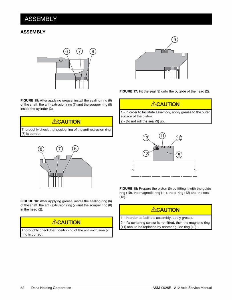
FIGURE 15: After applying grease, install the sealing ring (6) of the shaft, the anti-extrusion ring (7) and the scraper ring (8) inside the cylinder (3).
Thoroughly check that positioning of the anti-extrusion ring (7) is correct.
FIGURE 16: After applying grease, install the sealing ring (6) of the shaft, the anti-extrusion ring (7) and the scraper ring (8) in the head (2).
Thoroughly check that positioning of the anti-extrusion (7) ring is correct.
7 86 876
CAUTION
78 68 7 6
CAUTION
FIGURE 17: Fit the seal (9) onto the outside of the head (2).
1 - In order to facilitate assembly, apply grease to the outer surface of the piston.
2 - Do not roll the seal (9) up.
FIGURE 18: Prepare the piston (5) by fitting it with the guide ring (10), the magnetic ring (11), the o-ring (12) and the seal (13).
1 - In order to facilitate assembly, apply grease.
2 - If a centering sensor is not fitted, then the magnetic ring (11) should be replaced by another guide ring (10).
99
CAUTION
5
1011
12
13
12
13 11 10
5
CAUTION
ASSEMBLY
53Dana Holding CorporationASM-0025E - 212 Axle Service Manual
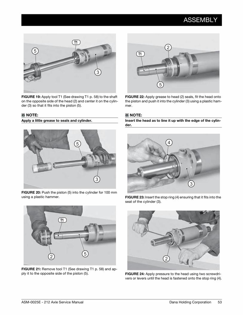
FIGURE 19: Apply tool T1 (See drawing T1 p. 58) to the shaft on the opposite side of the head (2) and center it on the cylin-der (3) so that it fits into the piston (5).
NOTE:
Apply a little grease to seals and cylinder.
FIGURE 20: Push the piston (5) into the cylinder for 100 mm using a plastic hammer.
FIGURE 21: Remove tool T1 (See drawing T1 p. 58) and ap-ply it to the opposite side of the piston (5).
5
3
T1
5
3
5
3
5
3
25
T1
52
FIGURE 22: Apply grease to head (2) seals, fit the head onto the piston and push it into the cylinder (3) using a plastic ham-mer.
NOTE:
Insert the head as to line it up with the edge of the cylin-
der.
FIGURE 23: Insert the stop ring (4) ensuring that it fits into the seat of the cylinder (3).
FIGURE 24: Apply pressure to the head using two screwdri-vers or levers until the head is fastened onto the stop ring (4).
5
T12
5
2
3
44
3
22
54
ASSEMBLY
Dana Holding Corporation ASM-0025E - 212 Axle Service Manual
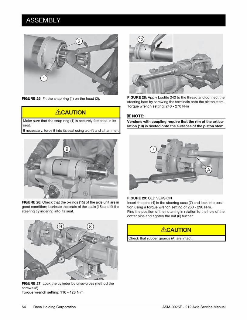
FIGURE 25: Fit the snap ring (1) on the head (2).
Make sure that the snap ring (1) is securely fastened in its seat.
If necessary, force it into its seat using a drift and a hammer.
FIGURE 26: Check that the o-rings (15) of the axle unit are in good condition; lubricate the seats of the seals (15) and fit the steering cylinder (9) into its seat.
FIGURE 27: Lock the cylinder by criss-cross method the screws (8). Torque wrench setting: 116 - 128 N·m
1
22
1
CAUTION
9
89
FIGURE 28: Apply Loctite 242 to the thread and connect the steering bars by screwing the terminals onto the piston stem. Torque wrench setting: 240 - 270 N·m
NOTE:
Versions with coupling require that the rim of the articu-
lation (13) is riveted onto the surfaces of the piston stem.
FIGURE 29: OLD VERSIONInsert the pins (4) in the steering case (7) and lock into posi-tion using a torque wrench setting of 260 - 290 N·m. Find the position of the notching in relation to the hole of the cotter pins and tighten the nut (6) further.
Check that rubber guards (A) are intact.
13
A
7
A
CAUTION
ASSEMBLY
55Dana Holding CorporationASM-0025E - 212 Axle Service Manual
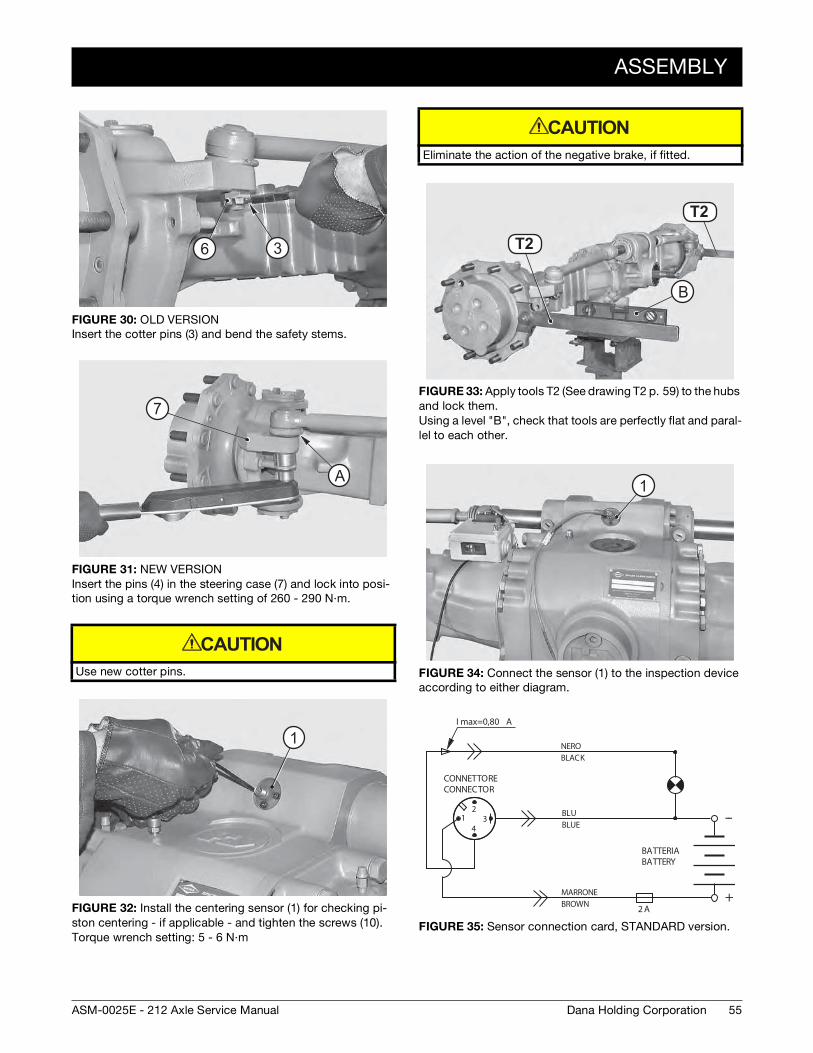
FIGURE 30: OLD VERSIONInsert the cotter pins (3) and bend the safety stems.
FIGURE 31: NEW VERSIONInsert the pins (4) in the steering case (7) and lock into posi-tion using a torque wrench setting of 260 - 290 N·m.
Use new cotter pins.
FIGURE 32: Install the centering sensor (1) for checking pi-ston centering - if applicable - and tighten the screws (10). Torque wrench setting: 5 - 6 N·m
36
A
7
A
CAUTION
1
Eliminate the action of the negative brake, if fitted.
FIGURE 33: Apply tools T2 (See drawing T2 p. 59) to the hubs and lock them. Using a level "B", check that tools are perfectly flat and paral-lel to each other.
FIGURE 34: Connect the sensor (1) to the inspection device according to either diagram.
FIGURE 35: Sensor connection card, STANDARD version.
CAUTION
T1 2
B
T1 2
T2
T2
B
1
12
34
--
+
I max=0,80 A
NEROBLACK
BLUBLUE
MARRONEBROWN 2 A
CONNETTORECONNECTOR
BATTERIABATTERY
56
ASSEMBLY
Dana Holding Corporation ASM-0025E - 212 Axle Service Manual
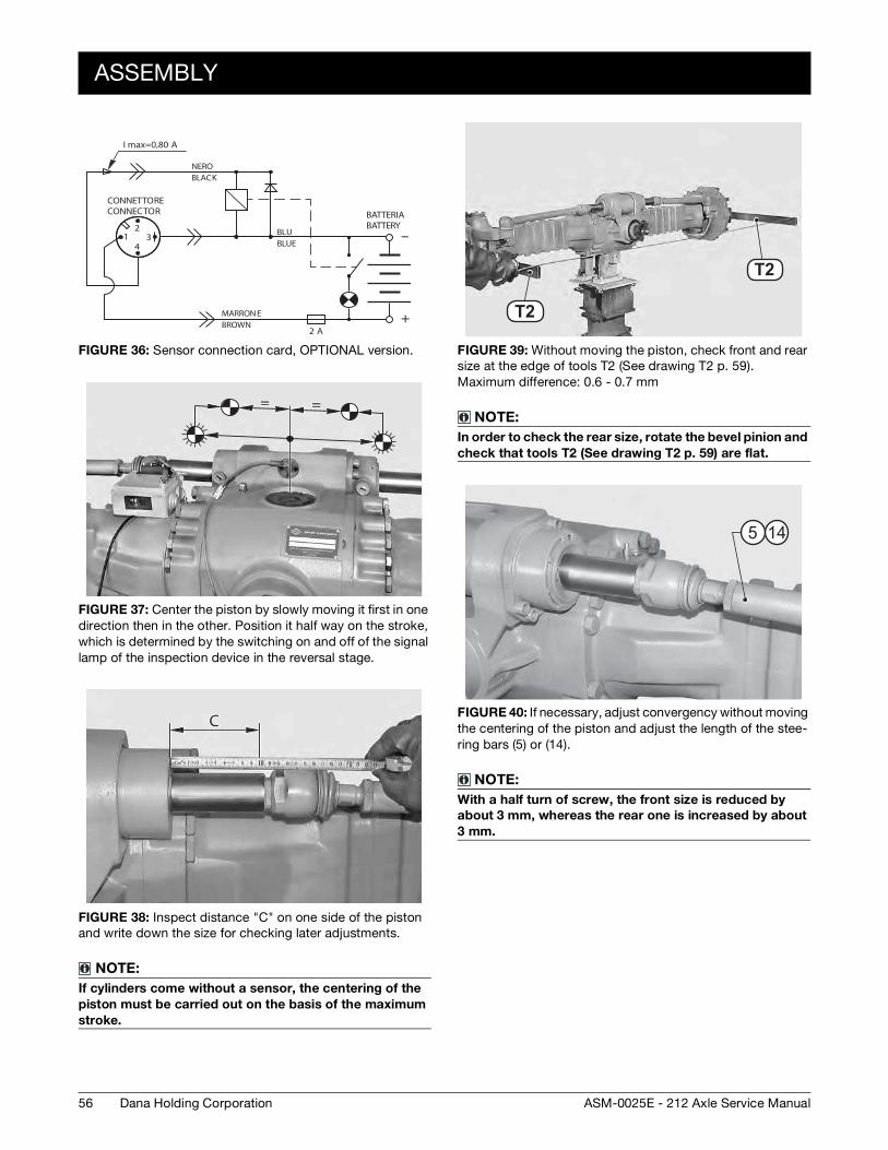
FIGURE 36: Sensor connection card, OPTIONAL version.
FIGURE 37: Center the piston by slowly moving it first in one direction then in the other. Position it half way on the stroke, which is determined by the switching on and off of the signal lamp of the inspection device in the reversal stage.
FIGURE 38: Inspect distance "C" on one side of the piston and write down the size for checking later adjustments.
NOTE:
If cylinders come without a sensor, the centering of the
piston must be carried out on the basis of the maximum
stroke.
12
34
--
+
I max=0,80 A
NEROBLACK
BLUBLUE
MARRONEBROWN
2 A
CONNETTORECONNECTOR BATTERIA
BATTERY
== === =
CCC
FIGURE 39: Without moving the piston, check front and rear size at the edge of tools T2 (See drawing T2 p. 59).Maximum difference: 0.6 - 0.7 mm
NOTE:
In order to check the rear size, rotate the bevel pinion and
check that tools T2 (See drawing T2 p. 59) are flat.
FIGURE 40: If necessary, adjust convergency without moving the centering of the piston and adjust the length of the stee-ring bars (5) or (14).
NOTE:
With a half turn of screw, the front size is reduced by
about 3 mm, whereas the rear one is increased by about
3 mm.
T1 2
T1 2
T2
T2
5 14
ASSEMBLY
57Dana Holding CorporationASM-0025E - 212 Axle Service Manual
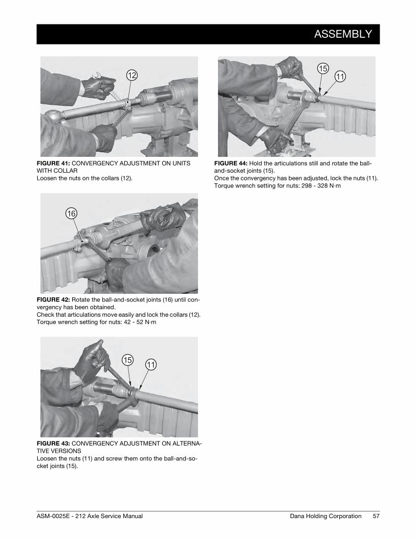
FIGURE 41: CONVERGENCY ADJUSTMENT ON UNITS WITH COLLAR Loosen the nuts on the collars (12).
FIGURE 42: Rotate the ball-and-socket joints (16) until con-vergency has been obtained. Check that articulations move easily and lock the collars (12). Torque wrench setting for nuts: 42 - 52 N·m
FIGURE 43: CONVERGENCY ADJUSTMENT ON ALTERNA-TIVE VERSIONS Loosen the nuts (11) and screw them onto the ball-and-so-cket joints (15).
12
16
15 11
FIGURE 44: Hold the articulations still and rotate the ball-and-socket joints (15). Once the convergency has been adjusted, lock the nuts (11). Torque wrench setting for nuts: 298 - 328 N·m
1511
58
SPECIAL TOOLS
Dana Holding Corporation ASM-0025E - 212 Axle Service Manual
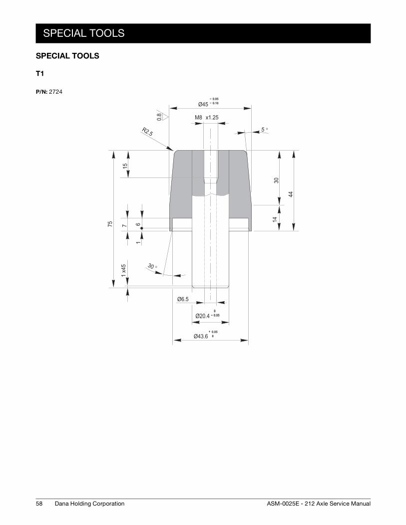
SPECIAL TOOLS
T1
P/N: 2724
0.8
-- 0.05-- 0.10Ø45
x1.25M8
5 °
30
44
14
15
75 7 61
30 °x45
1
Ø6.5
0-- 0.05Ø20.4
+ 0.050Ø43.6
R2.5
SPECIAL TOOLS
59Dana Holding CorporationASM-0025E - 212 Axle Service Manual
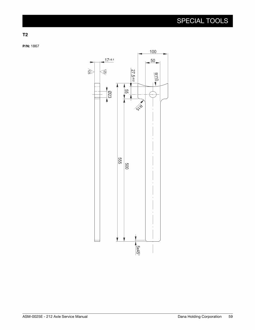
T2
P/N: 1867
125
125
x45°5
17±0.1 50
100
R110R15
27.5±0.2
55500
555
Ø23

60
SPECIAL TOOLS
Dana Holding Corporation ASM-0025E - 212 Axle Service Manual
61Dana Holding CorporationASM-0025E - 212 Axle Service Manual
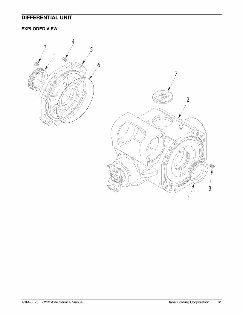
DIFFERENTIAL UNIT
EXPLODED VIEW
1
2
3
5
67
13
4
62
DISASSEMBLY
Dana Holding Corporation ASM-0025E - 212 Axle Service Manual
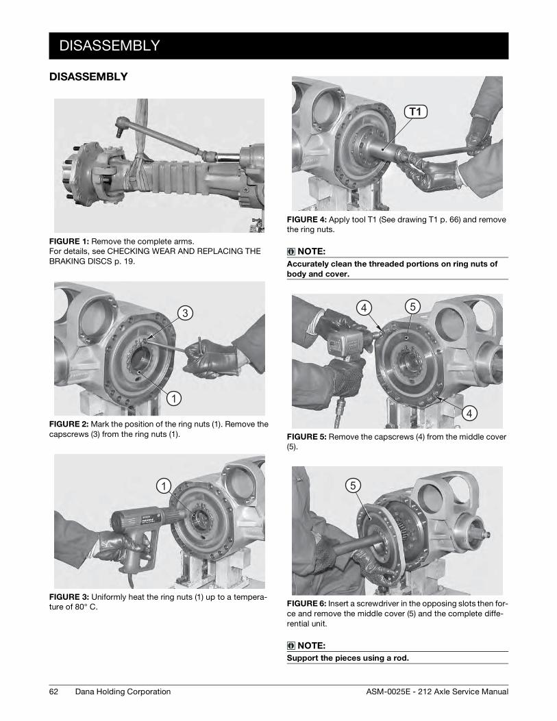
DISASSEMBLY
FIGURE 1: Remove the complete arms. For details, see CHECKING WEAR AND REPLACING THE BRAKING DISCS p. 19.
FIGURE 2: Mark the position of the ring nuts (1). Remove the capscrews (3) from the ring nuts (1).
FIGURE 3: Uniformly heat the ring nuts (1) up to a tempera-ture of 80° C.
3
1
1
FIGURE 4: Apply tool T1 (See drawing T1 p. 66) and remove the ring nuts.
NOTE:
Accurately clean the threaded portions on ring nuts of
body and cover.
FIGURE 5: Remove the capscrews (4) from the middle cover (5).
FIGURE 6: Insert a screwdriver in the opposing slots then for-ce and remove the middle cover (5) and the complete diffe-rential unit.
NOTE:
Support the pieces using a rod.
T1 3T1
4
4 5
5
DISASSEMBLY
63Dana Holding CorporationASM-0025E - 212 Axle Service Manual
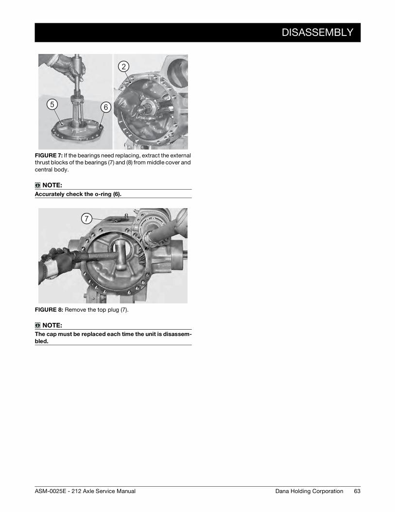
FIGURE 7: If the bearings need replacing, extract the external thrust blocks of the bearings (7) and (8) from middle cover and central body.
NOTE:
Accurately check the o-ring (6).
FIGURE 8: Remove the top plug (7).
NOTE:
The cap must be replaced each time the unit is disassem-
bled.
65
2
��7
64
ASSEMBLY
Dana Holding Corporation ASM-0025E - 212 Axle Service Manual
ASSEMBLY
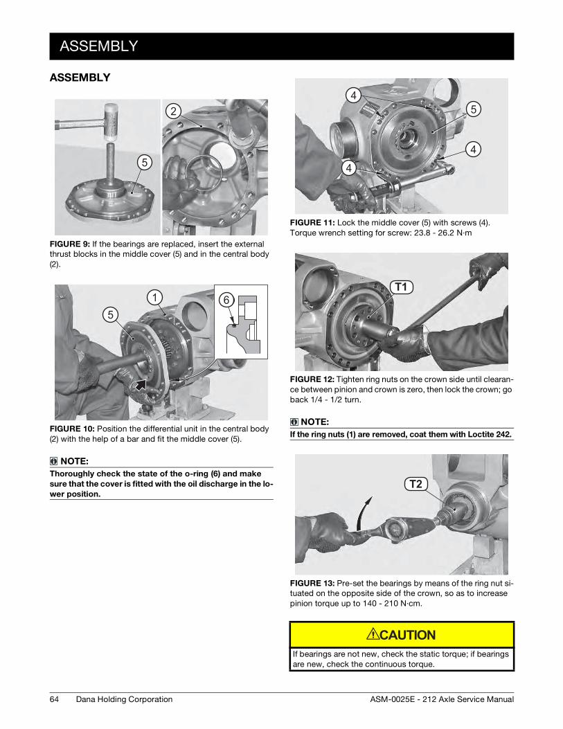
FIGURE 9: If the bearings are replaced, insert the external thrust blocks in the middle cover (5) and in the central body (2).
FIGURE 10: Position the differential unit in the central body (2) with the help of a bar and fit the middle cover (5).
NOTE:
Thoroughly check the state of the o-ring (6) and make
sure that the cover is fitted with the oil discharge in the lo-
wer position.
5
2
65
1
FIGURE 11: Lock the middle cover (5) with screws (4). Torque wrench setting for screw: 23.8 - 26.2 N·m
FIGURE 12: Tighten ring nuts on the crown side until clearan-ce between pinion and crown is zero, then lock the crown; go back 1/4 - 1/2 turn.
NOTE:
If the ring nuts (1) are removed, coat them with Loctite 242.
FIGURE 13: Pre-set the bearings by means of the ring nut si-tuated on the opposite side of the crown, so as to increase pinion torque up to 140 - 210 N·cm.
If bearings are not new, check the static torque; if bearings are new, check the continuous torque.
54
4
4
T1 3T1
T1 9T2
CAUTION
ASSEMBLY
65Dana Holding CorporationASM-0025E - 212 Axle Service Manual
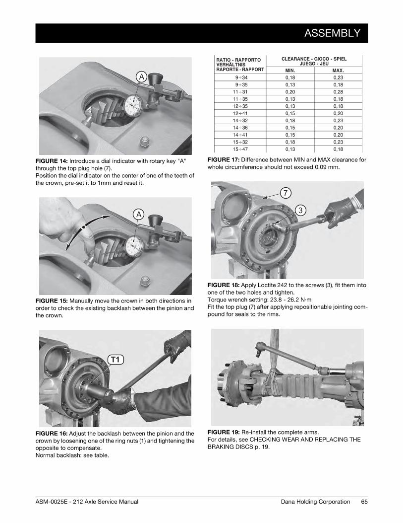
FIGURE 14: Introduce a dial indicator with rotary key "A" through the top plug hole (7). Position the dial indicator on the center of one of the teeth of the crown, pre-set it to 1mm and reset it.
FIGURE 15: Manually move the crown in both directions in order to check the existing backlash between the pinion and the crown.
FIGURE 16: Adjust the backlash between the pinion and the crown by loosening one of the ring nuts (1) and tightening the opposite to compensate. Normal backlash: see table.
AA
AA
T1 3T1
FIGURE 17: Difference between MIN and MAX clearance for whole circumference should not exceed 0.09 mm.
FIGURE 18: Apply Loctite 242 to the screws (3), fit them into one of the two holes and tighten. Torque wrench setting: 23.8 - 26.2 N·m Fit the top plug (7) after applying repositionable jointing com-pound for seals to the rims.
FIGURE 19: Re-install the complete arms. For details, see CHECKING WEAR AND REPLACING THE BRAKING DISCS p. 19.
7
3
66
SPECIAL TOOLS
Dana Holding Corporation ASM-0025E - 212 Axle Service Manual
SPECIAL TOOLS
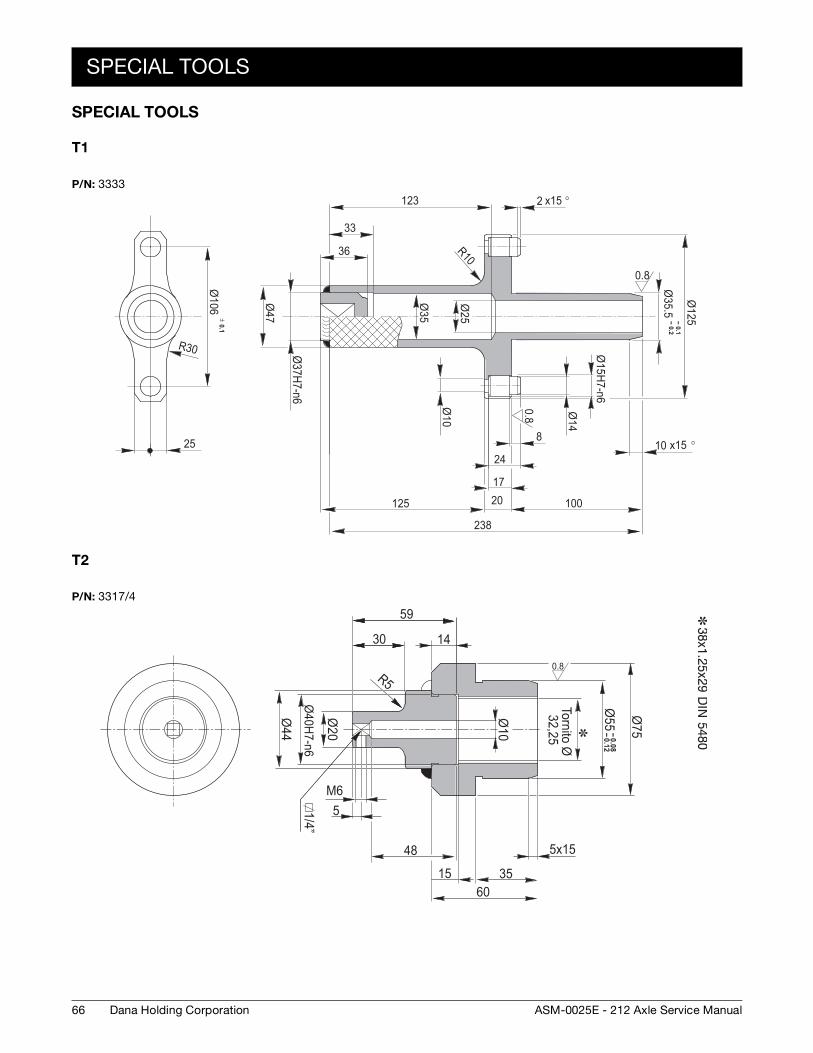
T1
T2
P/N: 3333
0.80.8
Ø125
Ø35.5
x15 °2
1002017
24
8
Ø14
Ø15H7-n6
238
33
Ø10
x15 °10
Ø25
Ø35
123
36
Ø47
R10
Ø37H7-n6
Ø106
± 0.1
R30
25
125
-- 0.1-- 0.2
P/N: 3317/4
0.8
-- 0.08-- 0.12
Ø55 Ø
75
1430
59
Ø20
Ø44
Ø40H7-n6
M65
48
1560
35
5x15
Ø10
R5
1/4”
Tornito Ø32,25
67Dana Holding CorporationASM-0025E - 212 Axle Service Manual
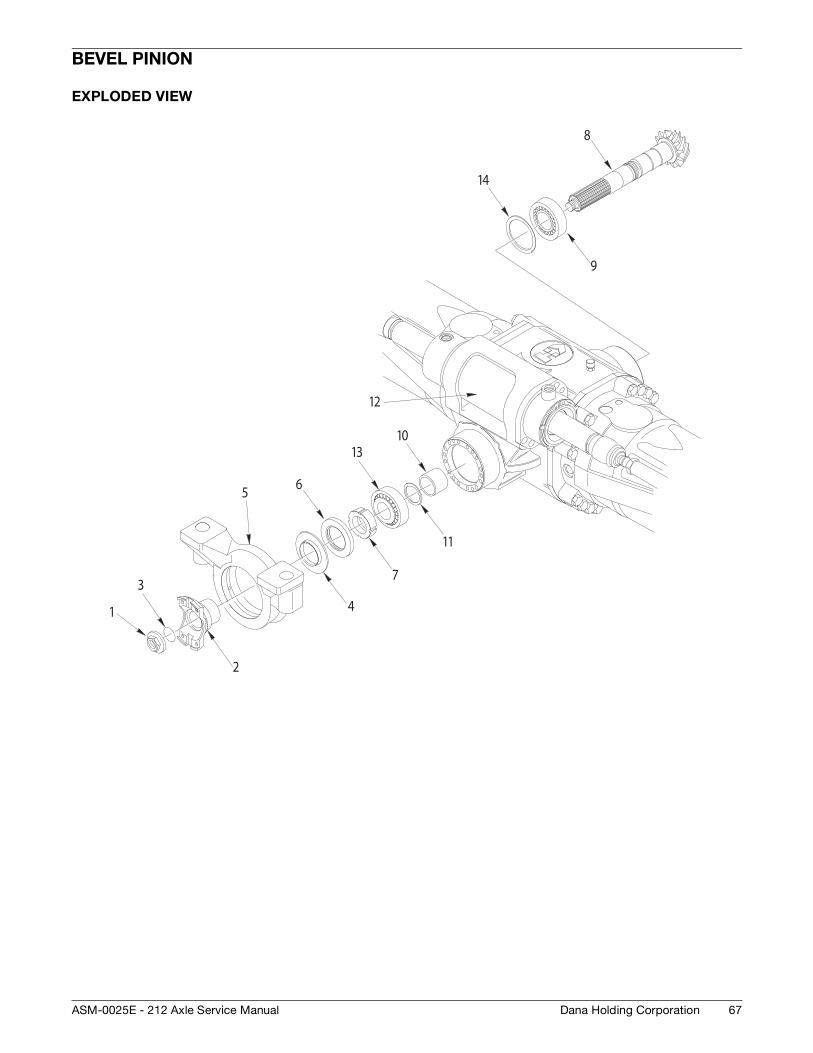
BEVEL PINION
EXPLODED VIEW
1
2
3
5 6
7
10
4
11
13
12
8
9
14
68
DISASSEMBLY
Dana Holding Corporation ASM-0025E - 212 Axle Service Manual
DISASSEMBLY
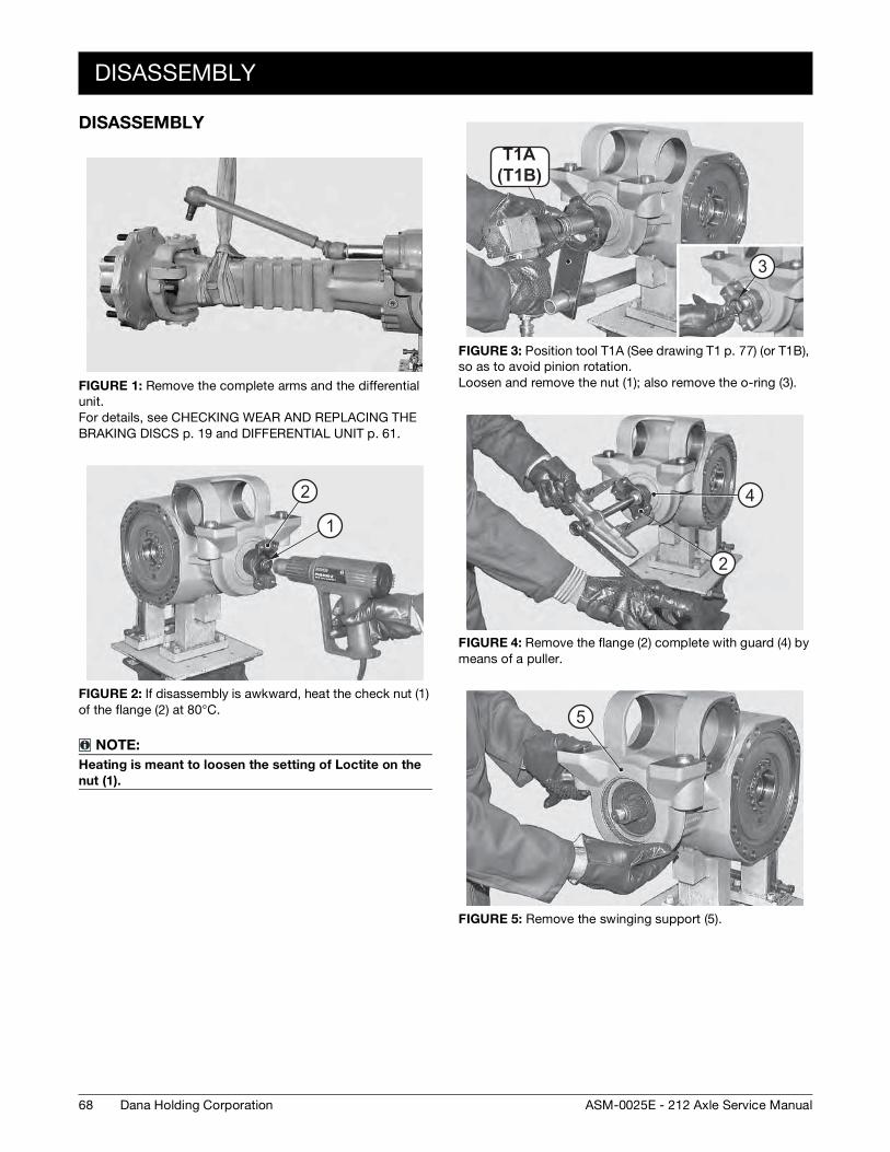
FIGURE 1: Remove the complete arms and the differential unit. For details, see CHECKING WEAR AND REPLACING THE BRAKING DISCS p. 19 and DIFFERENTIAL UNIT p. 61.
FIGURE 2: If disassembly is awkward, heat the check nut (1) of the flange (2) at 80°C.
NOTE:
Heating is meant to loosen the setting of Loctite on the
nut (1).
2
1
FIGURE 3: Position tool T1A (See drawing T1 p. 77) (or T1B), so as to avoid pinion rotation. Loosen and remove the nut (1); also remove the o-ring (3).
FIGURE 4: Remove the flange (2) complete with guard (4) by means of a puller.
FIGURE 5: Remove the swinging support (5).
(T20B )T20AT1A
(T1B)
3
4
2
5
DISASSEMBLY
69Dana Holding CorporationASM-0025E - 212 Axle Service Manual
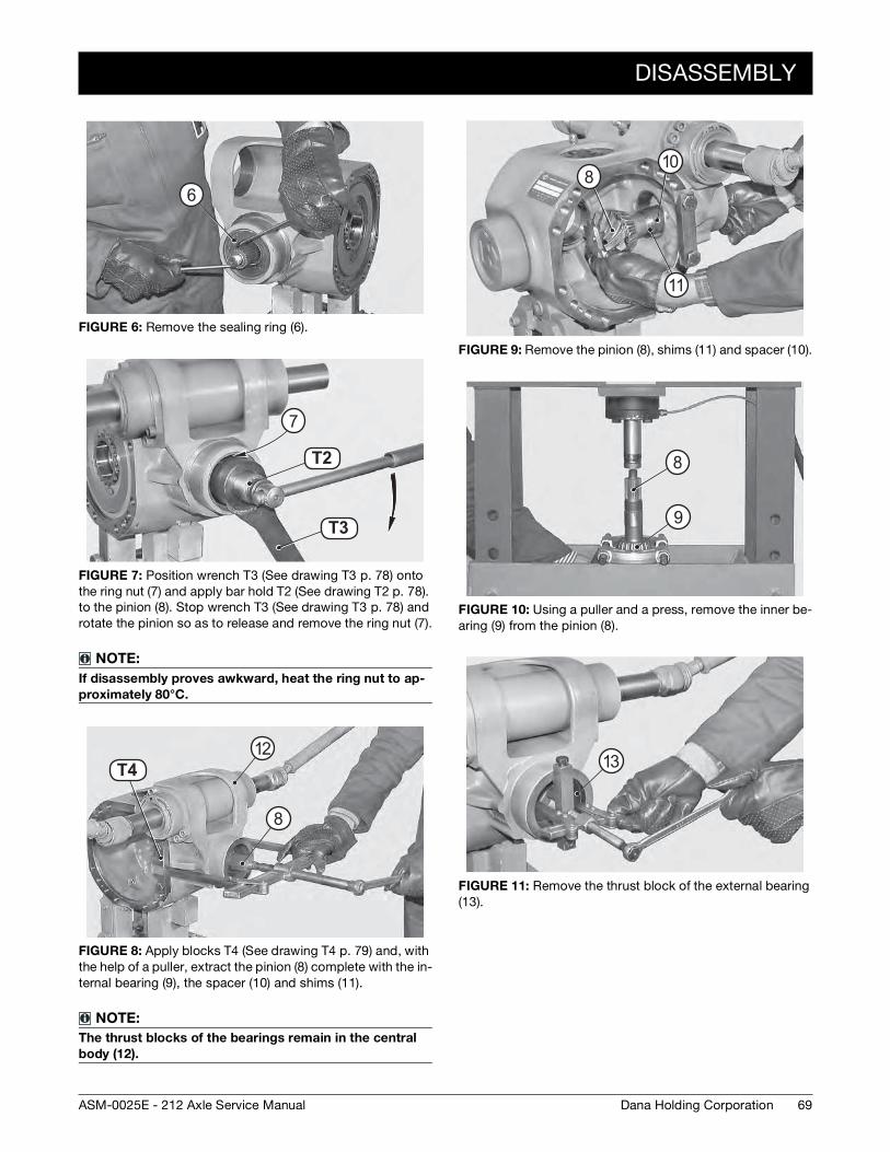
FIGURE 6: Remove the sealing ring (6).
FIGURE 7: Position wrench T3 (See drawing T3 p. 78) onto the ring nut (7) and apply bar hold T2 (See drawing T2 p. 78). to the pinion (8). Stop wrench T3 (See drawing T3 p. 78) and rotate the pinion so as to release and remove the ring nut (7).
NOTE:
If disassembly proves awkward, heat the ring nut to ap-
proximately 80°C.
FIGURE 8: Apply blocks T4 (See drawing T4 p. 79) and, with the help of a puller, extract the pinion (8) complete with the in-ternal bearing (9), the spacer (10) and shims (11).
NOTE:
The thrust blocks of the bearings remain in the central
body (12).
6
T2 1
T2 2
T2
T3
7
T2 3T4
8
12
FIGURE 9: Remove the pinion (8), shims (11) and spacer (10).
FIGURE 10: Using a puller and a press, remove the inner be-aring (9) from the pinion (8).
FIGURE 11: Remove the thrust block of the external bearing (13).
8
11
10
8
9
13
70
DISASSEMBLY
Dana Holding Corporation ASM-0025E - 212 Axle Service Manual
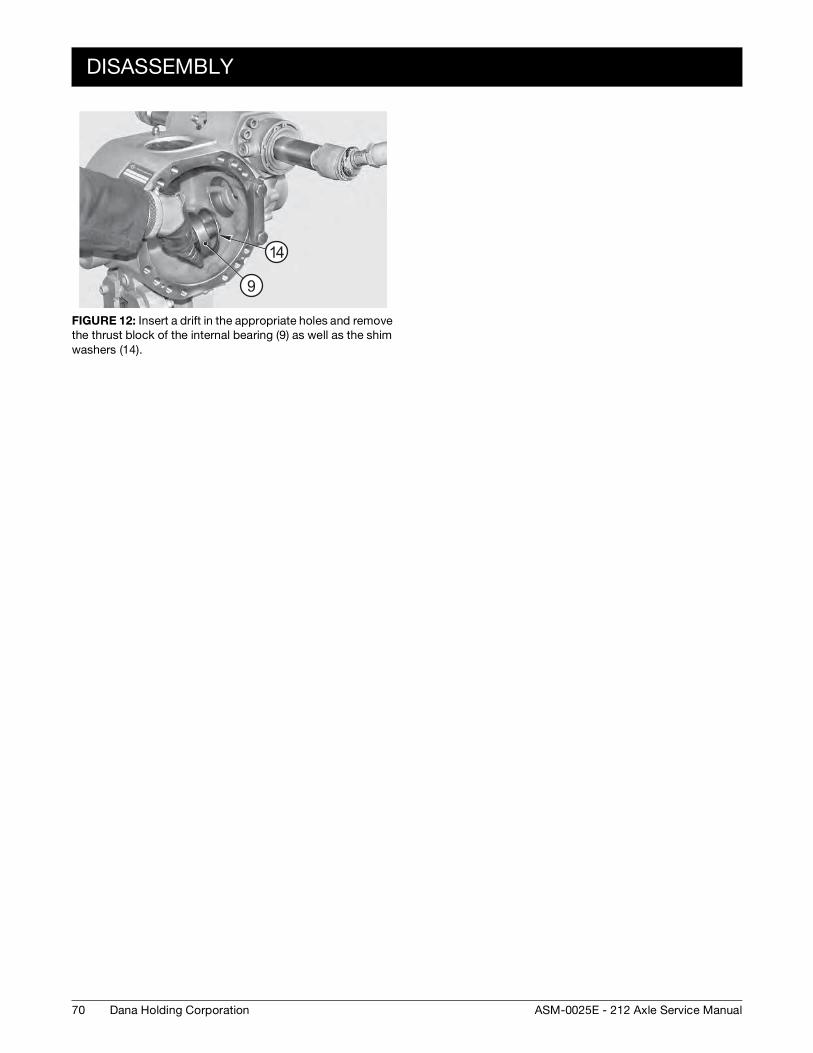
FIGURE 12: Insert a drift in the appropriate holes and remove the thrust block of the internal bearing (9) as well as the shim washers (14).
9
14
ASSEMBLY
71Dana Holding CorporationASM-0025E - 212 Axle Service Manual
ASSEMBLY
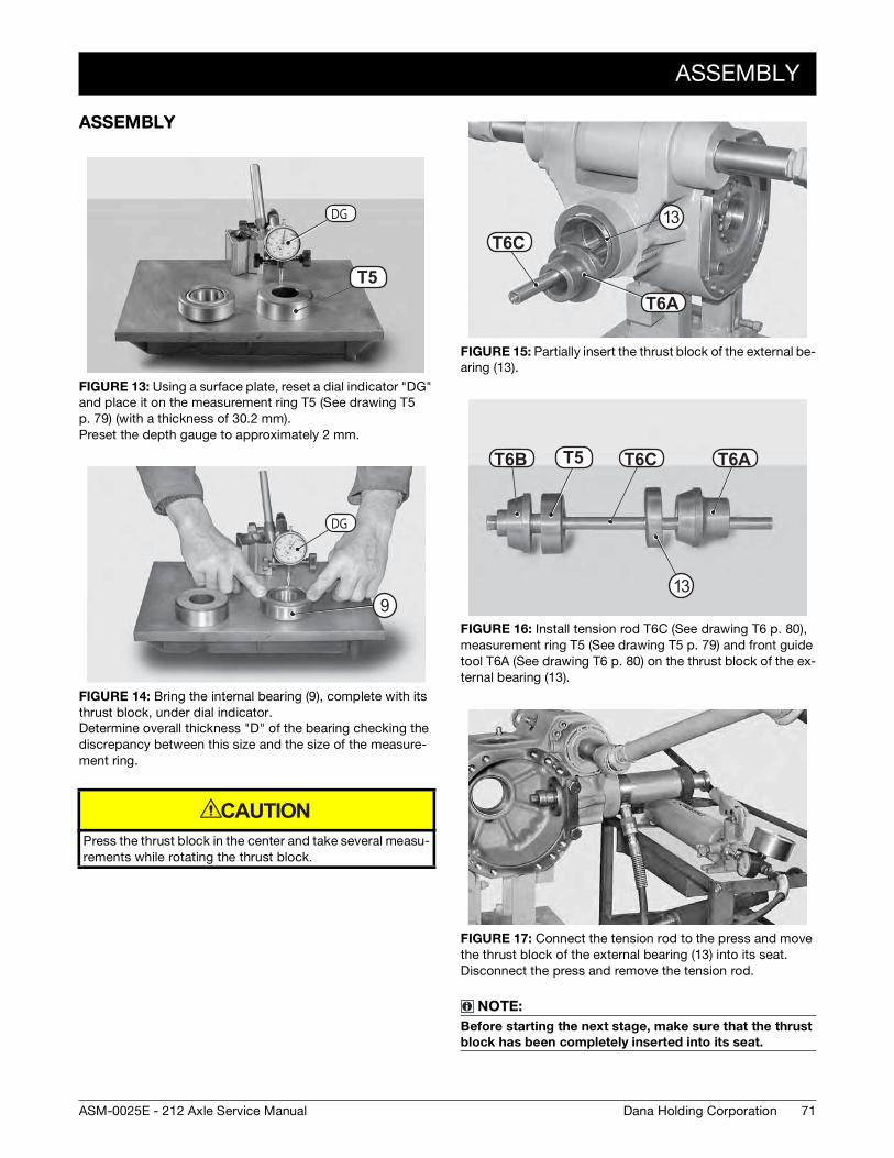
FIGURE 13: Using a surface plate, reset a dial indicator "DG" and place it on the measurement ring T5 (See drawing T5 p. 79) (with a thickness of 30.2 mm). Preset the depth gauge to approximately 2 mm.
FIGURE 14: Bring the internal bearing (9), complete with its thrust block, under dial indicator. Determine overall thickness "D" of the bearing checking the discrepancy between this size and the size of the measure-ment ring.
Press the thrust block in the center and take several measu-rements while rotating the thrust block.
T2 4
DG
T5
DG
9
CAUTION
FIGURE 15: Partially insert the thrust block of the external be-aring (13).
FIGURE 16: Install tension rod T6C (See drawing T6 p. 80), measurement ring T5 (See drawing T5 p. 79) and front guide tool T6A (See drawing T6 p. 80) on the thrust block of the ex-ternal bearing (13).
FIGURE 17: Connect the tension rod to the press and move the thrust block of the external bearing (13) into its seat. Disconnect the press and remove the tension rod.
NOTE:
Before starting the next stage, make sure that the thrust
block has been completely inserted into its seat.
T25A
T25CT6C
T6A
13
T25B T2 4 T25C T25AT6B T6C T6AT5
13
72
ASSEMBLY
Dana Holding Corporation ASM-0025E - 212 Axle Service Manual
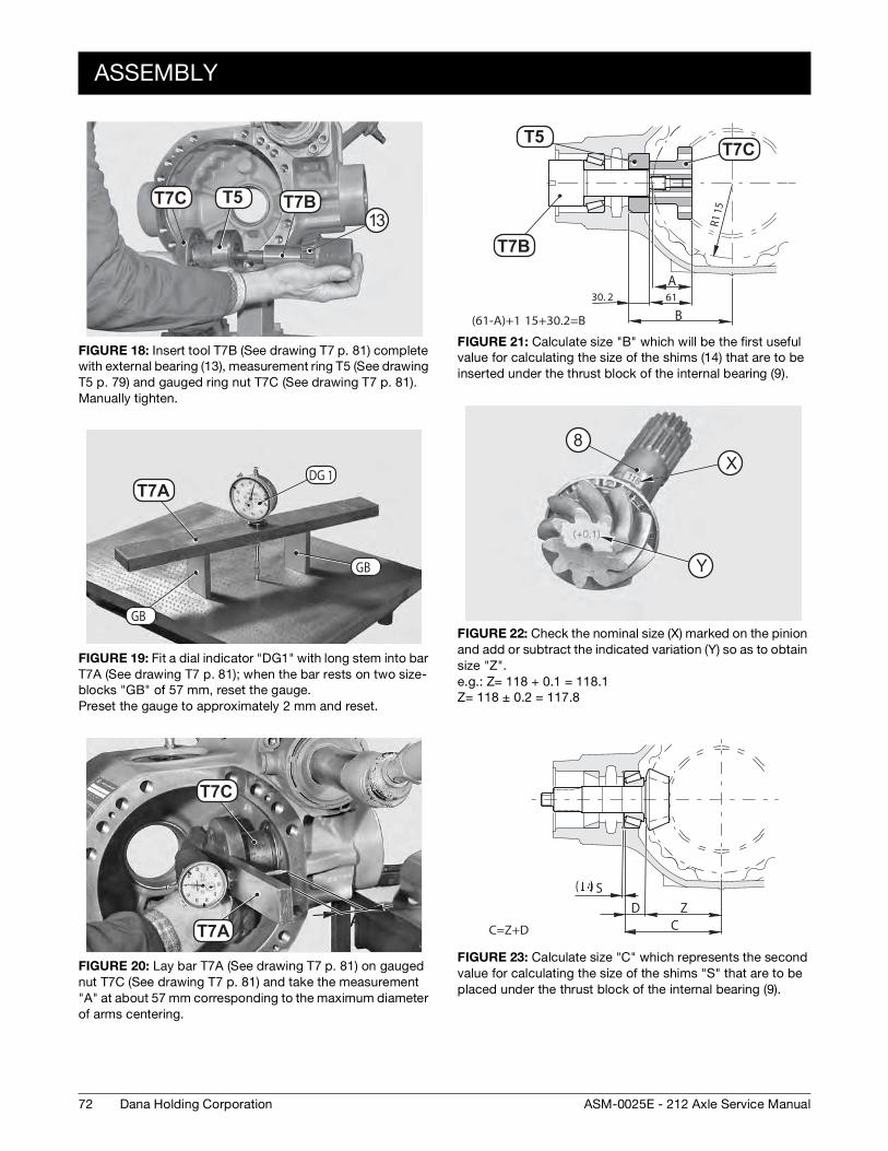
FIGURE 18: Insert tool T7B (See drawing T7 p. 81) complete with external bearing (13), measurement ring T5 (See drawing T5 p. 79) and gauged ring nut T7C (See drawing T7 p. 81). Manually tighten.
FIGURE 19: Fit a dial indicator "DG1" with long stem into bar T7A (See drawing T7 p. 81); when the bar rests on two size- blocks "GB" of 57 mm, reset the gauge. Preset the gauge to approximately 2 mm and reset.
FIGURE 20: Lay bar T7A (See drawing T7 p. 81) on gauged nut T7C (See drawing T7 p. 81) and take the measurement "A" at about 57 mm corresponding to the maximum diameter of arms centering.
T26BT26C T2 4 T7BT7C T513
T26ADG 1
GB
GB
T7A
T26C
T26A AA
T7C
T7A
FIGURE 21: Calculate size "B" which will be the first useful value for calculating the size of the shims (14) that are to be inserted under the thrust block of the internal bearing (9).
FIGURE 22: Check the nominal size (X) marked on the pinion and add or subtract the indicated variation (Y) so as to obtain size "Z". e.g.: Z= 118 + 0.1 = 118.1 Z= 118 ± 0.2 = 117.8
FIGURE 23: Calculate size "C" which represents the second value for calculating the size of the shims "S" that are to be placed under the thrust block of the internal bearing (9).
6130. 2A
(61-A)+1 15+30.2=B B
R115
T2 4
T26B
T26C
T7B
T7CT5
X
Y
8X
Y
ZC
SD
( )
C=Z+D
ASSEMBLY
73Dana Holding CorporationASM-0025E - 212 Axle Service Manual
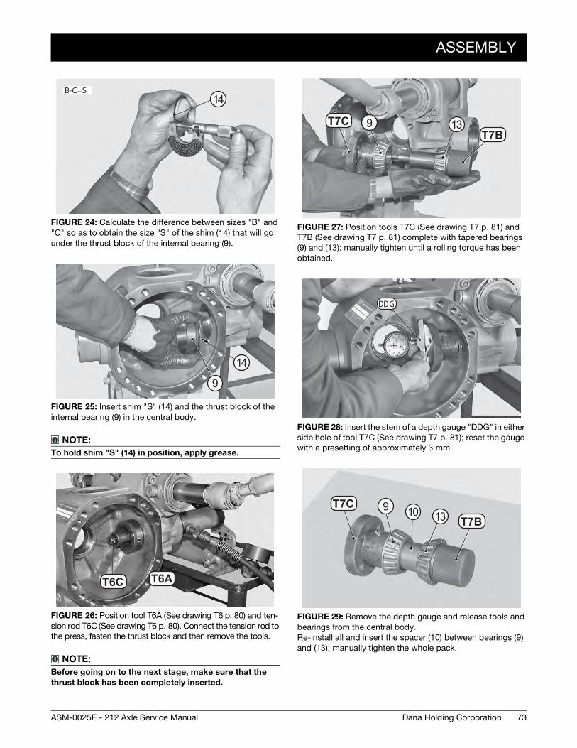
FIGURE 24: Calculate the difference between sizes "B" and "C" so as to obtain the size "S" of the shim (14) that will go under the thrust block of the internal bearing (9).
FIGURE 25: Insert shim "S" (14) and the thrust block of the internal bearing (9) in the central body.
NOTE:
To hold shim "S" (14) in position, apply grease.
FIGURE 26: Position tool T6A (See drawing T6 p. 80) and ten-sion rod T6C (See drawing T6 p. 80). Connect the tension rod to the press, fasten the thrust block and then remove the tools.
NOTE:
Before going on to the next stage, make sure that the
thrust block has been completely inserted.
B-C=S14
9
14
T25C T25AT6C T6A
FIGURE 27: Position tools T7C (See drawing T7 p. 81) and T7B (See drawing T7 p. 81) complete with tapered bearings (9) and (13); manually tighten until a rolling torque has been obtained.
FIGURE 28: Insert the stem of a depth gauge "DDG" in either side hole of tool T7C (See drawing T7 p. 81); reset the gauge with a presetting of approximately 3 mm.
FIGURE 29: Remove the depth gauge and release tools and bearings from the central body. Re-install all and insert the spacer (10) between bearings (9) and (13); manually tighten the whole pack.
T26CT26B
T7CT7B
9 13
DD G
T26C
T26B
T7CT7B
91310
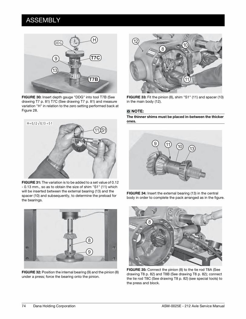
74
ASSEMBLY
Dana Holding Corporation ASM-0025E - 212 Axle Service Manual
FIGURE 30: Insert depth gauge "DDG" into tool T7B (See drawing T7 p. 81) T7C (See drawing T7 p. 81) and measure variation "H" in relation to the zero setting performed back at Figure 28.
FIGURE 31: The variation is to be added to a set value of 0.12 - 0.13 mm., so as to obtain the size of shim "S1" (11) which will be inserted between the external bearing (13) and the spacer (10) and subsequently, to determine the preload for the bearings.
FIGURE 32: Position the internal bearing (9) and the pinion (8) under a press; force the bearing onto the pinion.
DD G
T26C
T26B
H
T7B
T7C
H
9
13
H+ 0,12 √ 0,13 =S 1
11 S1
8
9
FIGURE 33: Fit the pinion (8), shim "S1" (11) and spacer (10) in the main body (12).
NOTE:
The thinner shims must be placed in-between the thicker
ones.
FIGURE 34: Insert the external bearing (13) in the central body in order to complete the pack arranged as in the figure.
FIGURE 35: Connect the pinion (8) to the tie rod T8A (See drawing T8 p. 82) and T8B (See drawing T8 p. 82); connect the tie rod T8C (See drawing T8 p. 82) (see special tools) to the press and block.
812
10
11
9131011
8
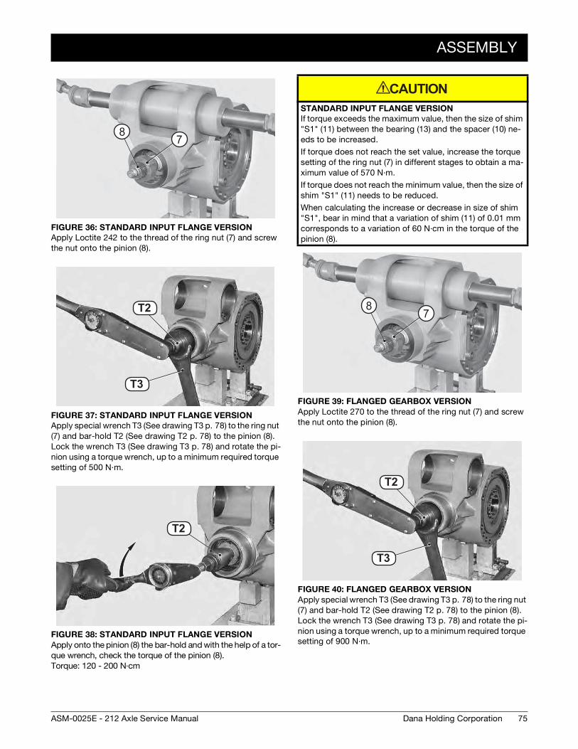
ASSEMBLY
75Dana Holding CorporationASM-0025E - 212 Axle Service Manual
FIGURE 36: STANDARD INPUT FLANGE VERSION
Apply Loctite 242 to the thread of the ring nut (7) and screw the nut onto the pinion (8).
FIGURE 37: STANDARD INPUT FLANGE VERSION
Apply special wrench T3 (See drawing T3 p. 78) to the ring nut (7) and bar-hold T2 (See drawing T2 p. 78) to the pinion (8). Lock the wrench T3 (See drawing T3 p. 78) and rotate the pi-nion using a torque wrench, up to a minimum required torque setting of 500 N·m.
FIGURE 38: STANDARD INPUT FLANGE VERSION
Apply onto the pinion (8) the bar-hold and with the help of a tor-que wrench, check the torque of the pinion (8). Torque: 120 - 200 N·cm
87
T2 2
T2 1
T3
T2
T1 9T2
STANDARD INPUT FLANGE VERSION
If torque exceeds the maximum value, then the size of shim "S1" (11) between the bearing (13) and the spacer (10) ne-eds to be increased.
If torque does not reach the set value, increase the torque setting of the ring nut (7) in different stages to obtain a ma-ximum value of 570 N·m.
If torque does not reach the minimum value, then the size of shim "S1" (11) needs to be reduced.
When calculating the increase or decrease in size of shim "S1", bear in mind that a variation of shim (11) of 0.01 mm corresponds to a variation of 60 N·cm in the torque of the pinion (8).
FIGURE 39: FLANGED GEARBOX VERSION
Apply Loctite 270 to the thread of the ring nut (7) and screw the nut onto the pinion (8).
FIGURE 40: FLANGED GEARBOX VERSION
Apply special wrench T3 (See drawing T3 p. 78) to the ring nut (7) and bar-hold T2 (See drawing T2 p. 78) to the pinion (8). Lock the wrench T3 (See drawing T3 p. 78) and rotate the pi-nion using a torque wrench, up to a minimum required torque setting of 900 N·m.
CAUTION
87
T2 2
T2 1
T3
T2
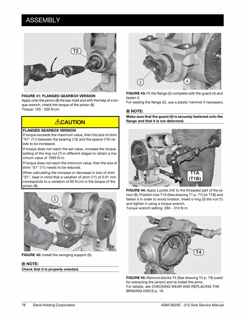
76
ASSEMBLY
Dana Holding Corporation ASM-0025E - 212 Axle Service Manual
FIGURE 41: FLANGED GEARBOX VERSION
Apply onto the pinion (8) the bar-hold and with the help of a tor-que wrench, check the torque of the pinion (8). Torque: 120 - 200 N·cm
FLANGED GEARBOX VERSION
If torque exceeds the maximum value, then the size of shim "S1" (11) between the bearing (13) and the spacer (10) ne-eds to be increased.
If torque does not reach the set value, increase the torque setting of the ring nut (7) in different stages to obtain a ma-ximum value of 1000 N·m.
If torque does not reach the minimum value, then the size of shim "S1" (11) needs to be reduced.
When calculating the increase or decrease in size of shim "S1", bear in mind that a variation of shim (11) of 0.01 mm corresponds to a variation of 60 N·cm in the torque of the pinion (8).
FIGURE 42: Install the swinging support (5).
NOTE:
Check that it is properly oriented.
T1 9T2
CAUTION
5
FIGURE 43: Fit the flange (2) complete with the guard (4) and fasten it. For seating the flange (2), use a plastic hammer if necessary.
NOTE:
Make sure that the guard (4) is securely fastened onto the
flange and that it is not deformed.
FIGURE 44: Apply Loctite 242 to the threaded part of the pi-nion (8). Position tool T1A (See drawing T1 p. 77) (or T1B) and fasten it in order to avoid rotation. Insert o-ring (3) the nut (1) and tighten it using a torque wrench. Torque wrench setting: 280 - 310 N·m
FIGURE 45: Remove blocks T4 (See drawing T4 p. 79) (used for extracting the pinion) and re-install the arms. For details, see CHECKING WEAR AND REPLACING THE BRAKING DISCS p. 19.
2 4
(T20B )T20AT1A
(T1B)
T2 3T4
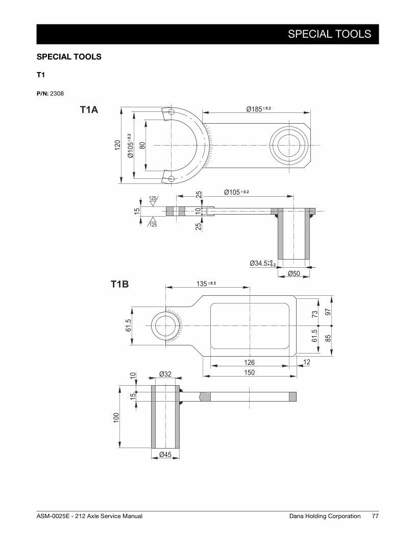
SPECIAL TOOLS
77Dana Holding CorporationASM-0025E - 212 Axle Service Manual
SPECIAL TOOLS
T1
P/N: 2308
80
± 0.
2Ø
105
120
15
± 0.2Ø10525
2510
Ø50
± 0.2Ø185
-- 0+ 0.2Ø34.5
125
125
61.5
100
1510
Ø45
126150
12
61.5
73 9785
135 ±0.5
Ø32
T1A
T1B
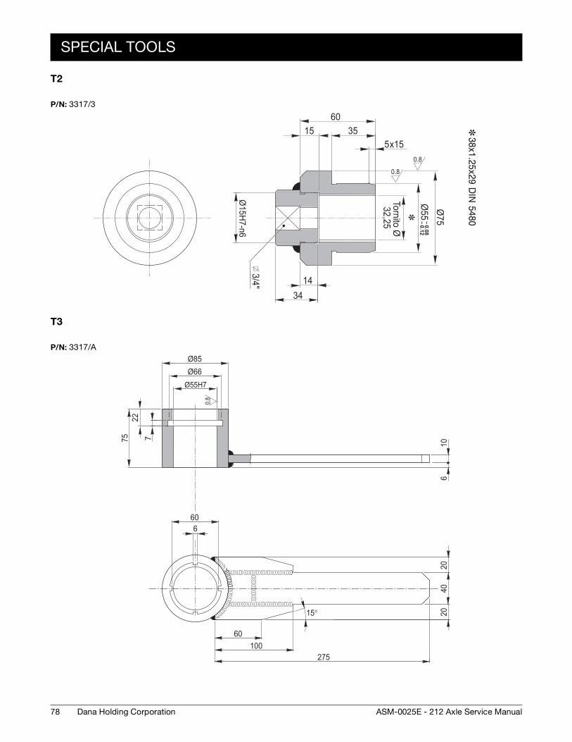
78
SPECIAL TOOLS
Dana Holding Corporation ASM-0025E - 212 Axle Service Manual
T2
T3
P/N: 3317/3
0.8
0.8
3/4"Ø
15H7-n6
– 0.08– 0.12
Ø55Ø
7535
x155
6015
1434
Tornito Ø32,25
P/N: 3317/A
0.8
Ø85
Ø55H7
7
60
Ø66
2275 10
620
4020
6
60100
275
15°
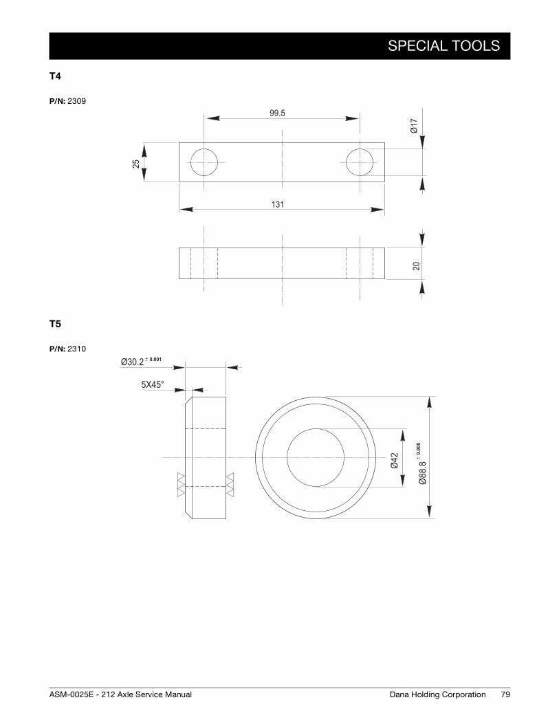
SPECIAL TOOLS
79Dana Holding CorporationASM-0025E - 212 Axle Service Manual
T4
T5
P/N: 2309
131
99.5
25
20Ø
17
P/N: 2310± 0.001Ø30.2
5X45°Ø
42 ± 0.
005
Ø88
.8
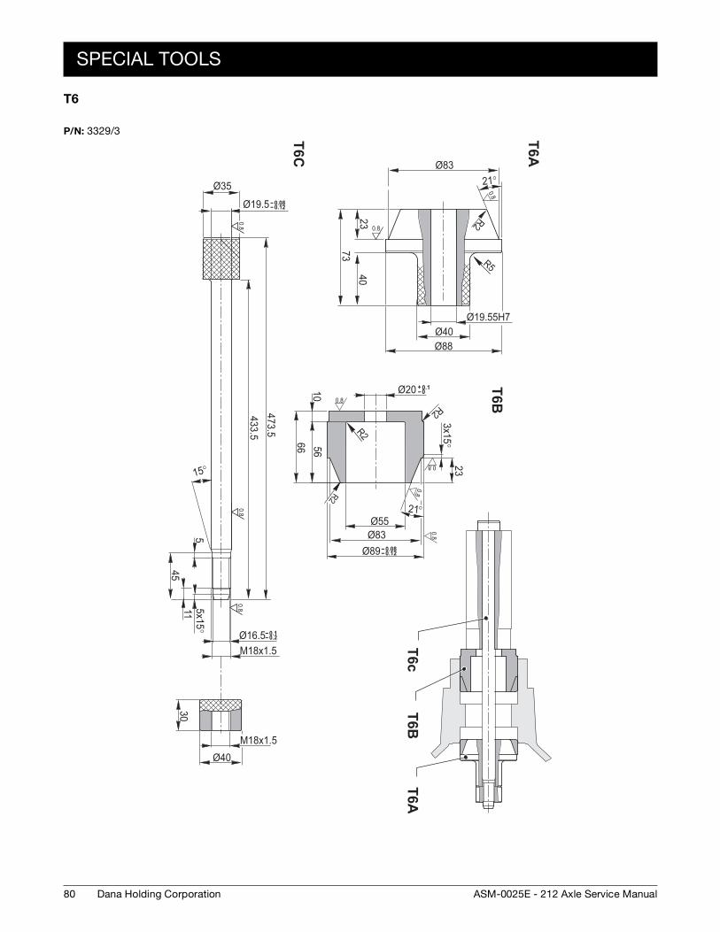
80
SPECIAL TOOLS
Dana Holding Corporation ASM-0025E - 212 Axle Service Manual
T6
P/N: 3329/3
0.80.8
0.8
T25CT25B
Ø35-- 0.08-- 0.12Ø19.5
433.5473.5
5
4511 5x15°
-- 0.1-- 0.2Ø16.5M18x1.5
30
M18x1.5Ø40
15°
233x15°
Ø55Ø83
5666
10
+ 0.1-- 0Ø20
R2
R2
-- 0.08-- 0.12Ø89
Ø19.55H7
2340
73
Ø40Ø88
Ø8321°
R2
R5
R221°
0.8
0.8
0.8
0.8
0.80.8
T6A
T6AT6B
T6c
T6B
T6C
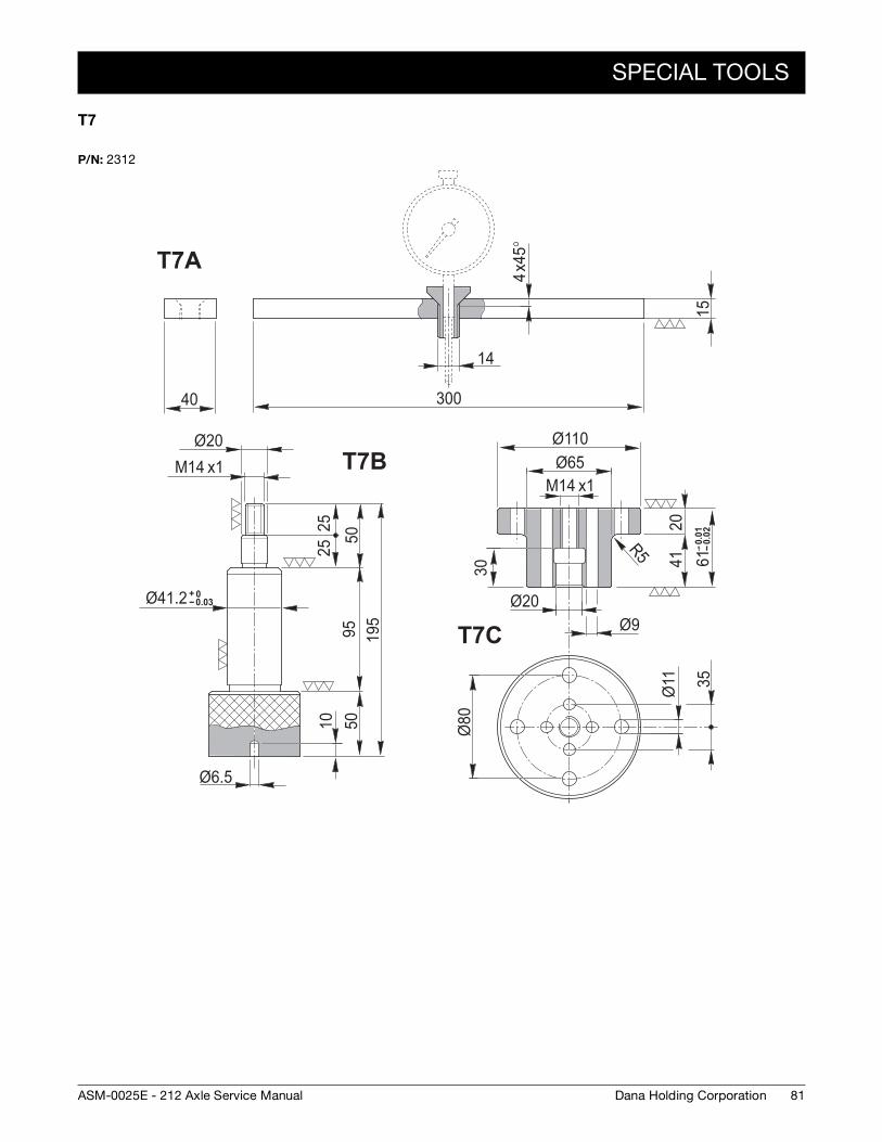
SPECIAL TOOLS
81Dana Holding CorporationASM-0025E - 212 Axle Service Manual
T7
P/N: 2312
+ 0-- 0.03Ø41.2
Ø20x1M14
2550
2595
5010
195
Ø110
x1M14Ø65
2041
-- 0.0
1--
0.02
6130
R5
40
15
300
14
x45°
4
Ø20Ø9
Ø80
35Ø11
Ø6.5
T7A
T7B
T7C
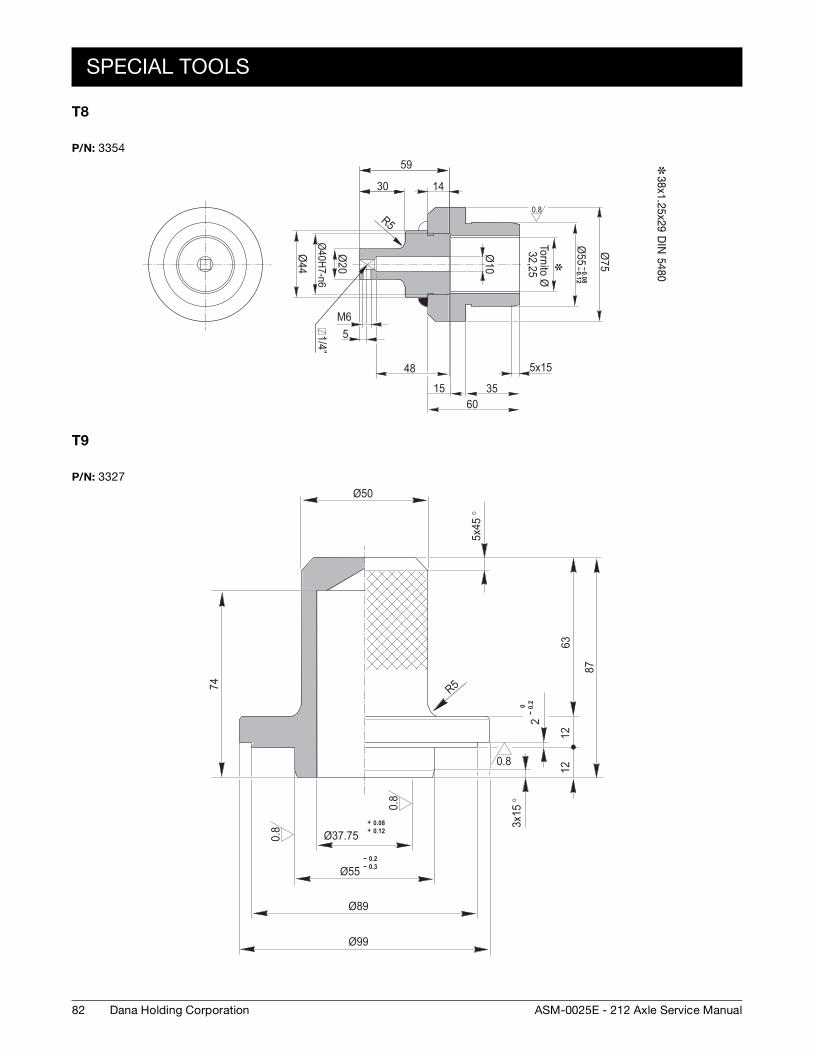
82
SPECIAL TOOLS
Dana Holding Corporation ASM-0025E - 212 Axle Service Manual
T8
T9
P/N: 3354
0.8
-- 0.08-- 0.12
Ø55 Ø
75
1430
59
Ø20
Ø44
Ø40H7-n6
M65
48
1560
35
5x15
Ø10
R5
1/4”
Tornito Ø32,25
P/N: 3327
0.8
0.8
0.8
Ø505x
45°
0--
0.2
12
3x15
°
1263
87
2
+ 0.08+ 0.12Ø37.75
-- 0.2-- 0.3Ø55
Ø89
Ø99
R574
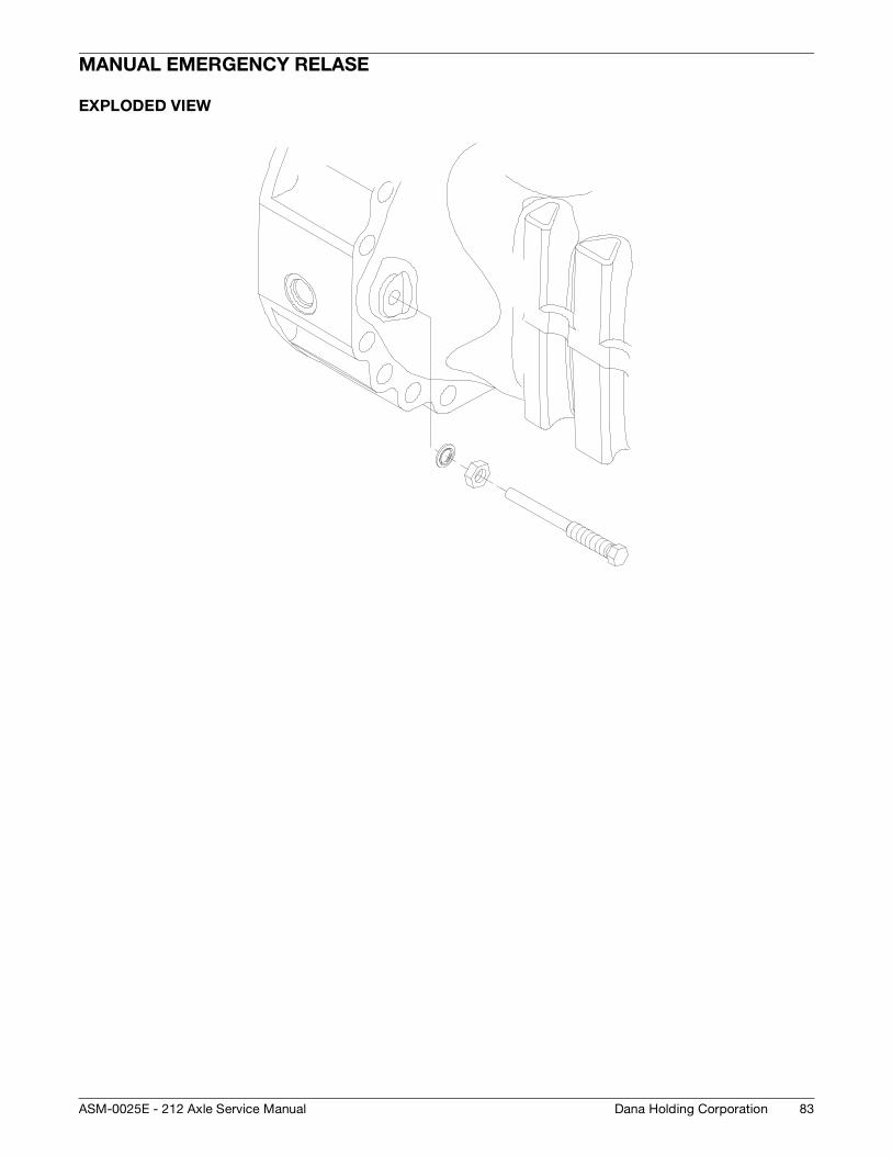
83Dana Holding CorporationASM-0025E - 212 Axle Service Manual
MANUAL EMERGENCY RELASE
EXPLODED VIEW
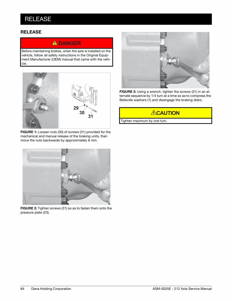
84
RELEASE
Dana Holding Corporation ASM-0025E - 212 Axle Service Manual
RELEASE
Before maintaining brakes, when the axle is installed on the vehicle, follow all safety instructions in the Original Equip-ment Manufacturer (OEM) manual that came with the vehi-cle.
FIGURE 1: Loosen nuts (30) of screws (31) provided for the mechanical and manual release of the braking units, then move the nuts backwards by approximately 8 mm.
FIGURE 2: Tighten screws (31) so as to fasten them onto the pressure plate (23).
DANGER
2930
31
FIGURE 3: Using a wrench, tighten the screws (31) in an al-ternate sequence by 1/4 turn at a time so as to compress the Belleville washers (1) and disengage the braking disks.
Tighten maximum by one turn.
CAUTION
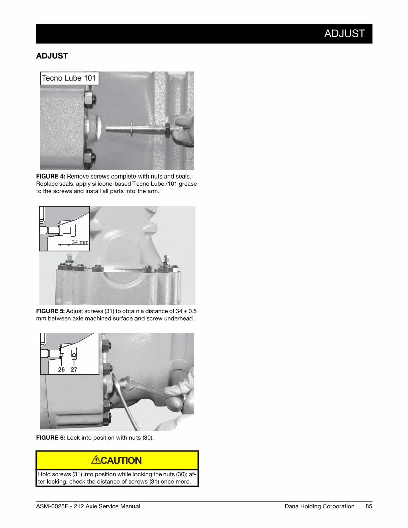
ADJUST
85Dana Holding CorporationASM-0025E - 212 Axle Service Manual
ADJUST
FIGURE 4: Remove screws complete with nuts and seals. Replace seals, apply silicone-based Tecno Lube /101 grease to the screws and install all parts into the arm.
FIGURE 5: Adjust screws (31) to obtain a distance of 34 ± 0.5 mm between axle machined surface and screw underhead.
FIGURE 6: Lock into position with nuts (30).
Hold screws (31) into position while locking the nuts (30); af-ter locking, check the distance of screws (31) once more.
Tecno Lube 101
34 mm
2726
CAUTION

86
ADJUST
Dana Holding Corporation ASM-0025E - 212 Axle Service Manual
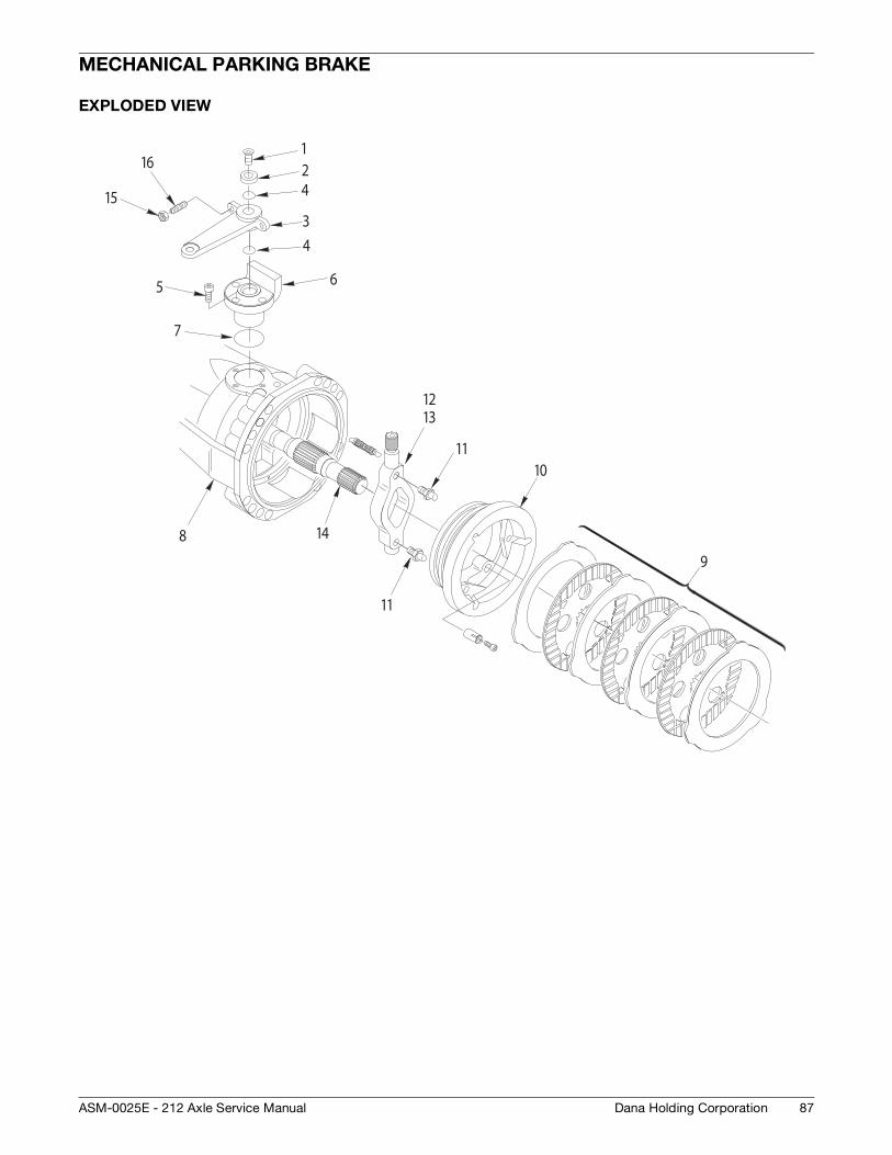
87Dana Holding CorporationASM-0025E - 212 Axle Service Manual
MECHANICAL PARKING BRAKE
EXPLODED VIEW
12
3
4
5 6
7
8
9
1011
13
14
4
11
12
16
15
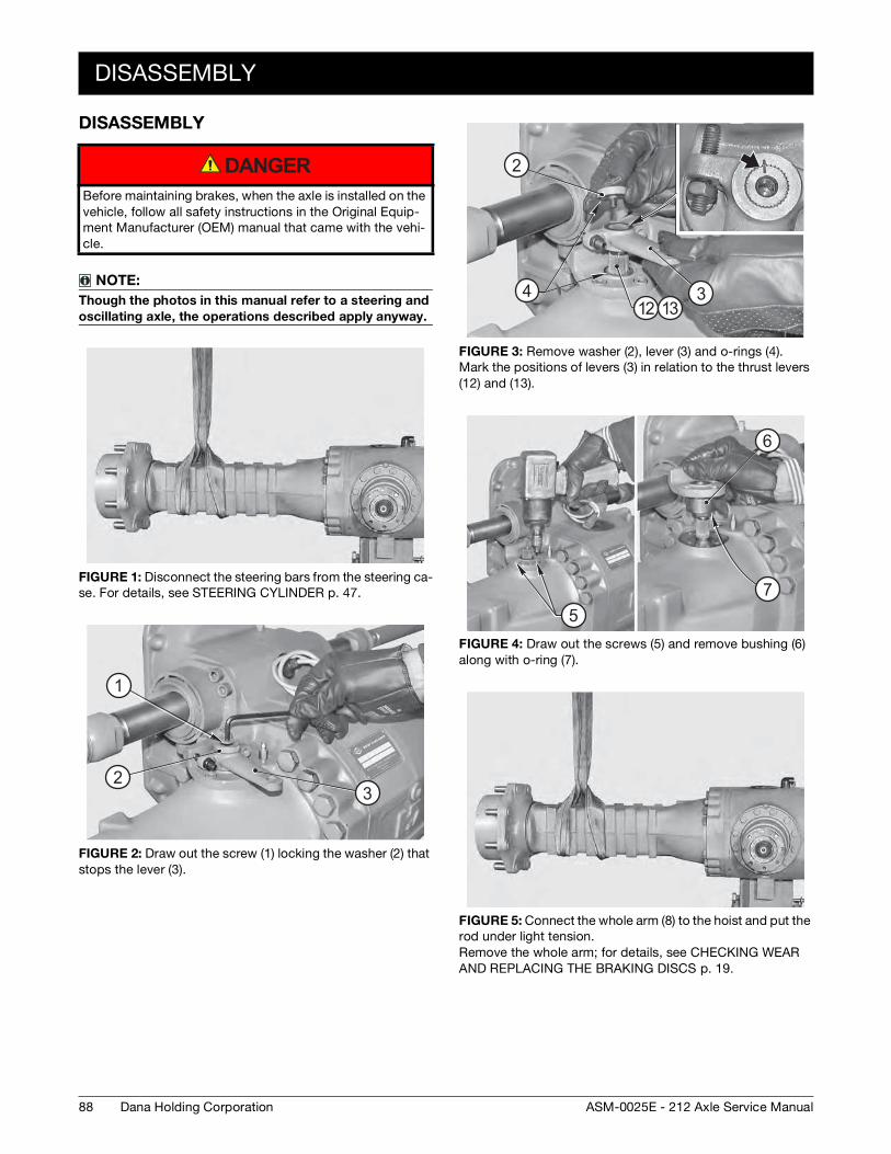
88
DISASSEMBLY
Dana Holding Corporation ASM-0025E - 212 Axle Service Manual
DISASSEMBLY
Before maintaining brakes, when the axle is installed on the vehicle, follow all safety instructions in the Original Equip-ment Manufacturer (OEM) manual that came with the vehi-cle.
NOTE:
Though the photos in this manual refer to a steering and
oscillating axle, the operations described apply anyway.
FIGURE 1: Disconnect the steering bars from the steering ca-se. For details, see STEERING CYLINDER p. 47.
FIGURE 2: Draw out the screw (1) locking the washer (2) that stops the lever (3).
DANGER
1
23
FIGURE 3: Remove washer (2), lever (3) and o-rings (4). Mark the positions of levers (3) in relation to the thrust levers (12) and (13).
FIGURE 4: Draw out the screws (5) and remove bushing (6) along with o-ring (7).
FIGURE 5: Connect the whole arm (8) to the hoist and put the rod under light tension. Remove the whole arm; for details, see CHECKING WEAR AND REPLACING THE BRAKING DISCS p. 19.
2
3412 13
5
6
7
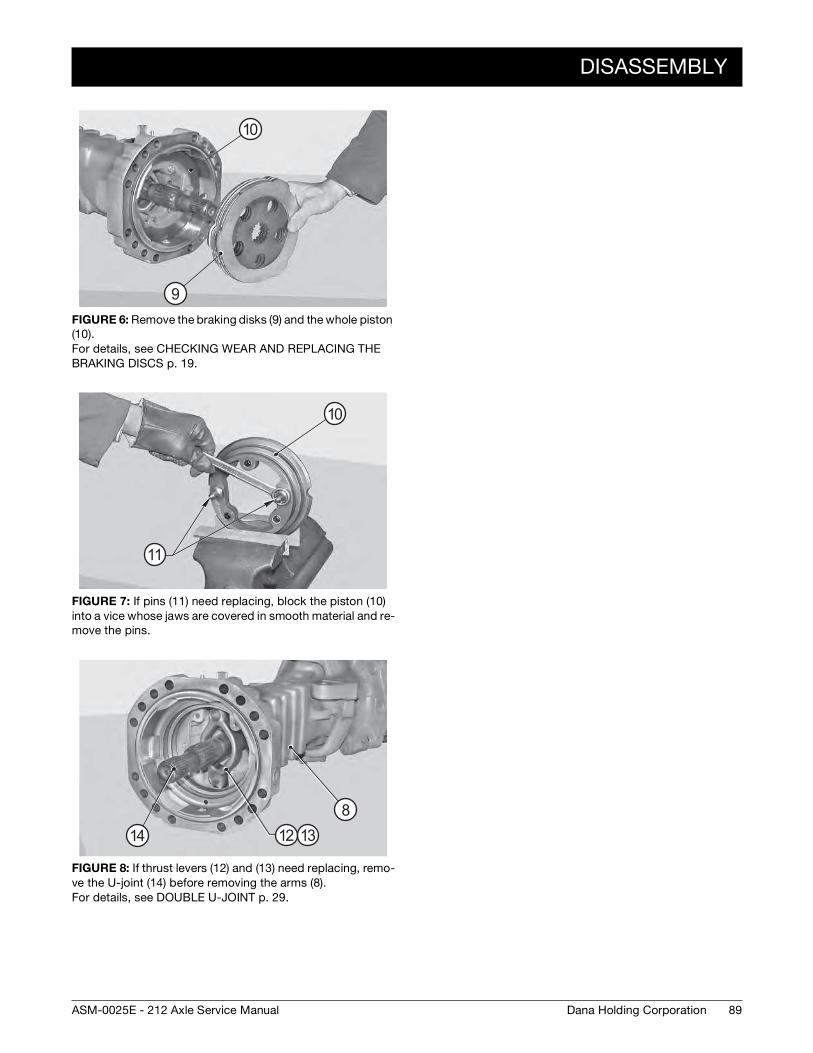
DISASSEMBLY
89Dana Holding CorporationASM-0025E - 212 Axle Service Manual
FIGURE 6: Remove the braking disks (9) and the whole piston (10). For details, see CHECKING WEAR AND REPLACING THE BRAKING DISCS p. 19.
FIGURE 7: If pins (11) need replacing, block the piston (10) into a vice whose jaws are covered in smooth material and re-move the pins.
FIGURE 8: If thrust levers (12) and (13) need replacing, remo-ve the U-joint (14) before removing the arms (8). For details, see DOUBLE U-JOINT p. 29.
9
10
10
11
812 1314
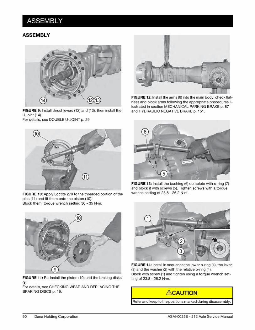
90
ASSEMBLY
Dana Holding Corporation ASM-0025E - 212 Axle Service Manual
ASSEMBLY
FIGURE 9: Install thrust levers (12) and (13), then install the U-joint (14). For details, see DOUBLE U-JOINT p. 29.
FIGURE 10: Apply Loctite 270 to the threaded portion of the pins (11) and fit them onto the piston (10). Block them: torque wrench setting 30 - 35 N·m.
FIGURE 11: Re-install the piston (10) and the braking disks (9). For details, see CHECKING WEAR AND REPLACING THE BRAKING DISCS p. 19.
12 1314
11
10
9
10
FIGURE 12: Install the arms (8) into the main body; check flat-ness and block arms following the appropriate procedures il-lustrated in section MECHANICAL PARKING BRAKE p. 87 and HYDRAULIC NEGATIVE BRAKE p. 151.
FIGURE 13: Install the bushing (6) complete with o-ring (7) and block it with screws (5). Tighten screws with a torque wrench setting of 23.8 - 26.2 N·m.
FIGURE 14: Install in sequence the lower o-ring (4), the lever (3) and the washer (2) with the relative o-ring (4). Block with screw (1) and tighten using a torque wrench set-ting of 23.8 - 26.2 N·m.
Refer and keep to the positions marked during disassembly.
5
6
1
2
3
CAUTION
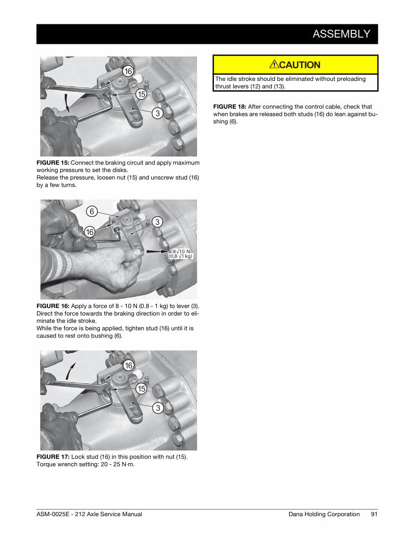
ASSEMBLY
91Dana Holding CorporationASM-0025E - 212 Axle Service Manual
FIGURE 15: Connect the braking circuit and apply maximum working pressure to set the disks. Release the pressure, loosen nut (15) and unscrew stud (16) by a few turns.
FIGURE 16: Apply a force of 8 - 10 N (0.8 - 1 kg) to lever (3). Direct the force towards the braking direction in order to eli-minate the idle stroke. While the force is being applied, tighten stud (16) until it is caused to rest onto bushing (6).
FIGURE 17: Lock stud (16) in this position with nut (15). Torque wrench setting: 20 - 25 N·m.
3
16
15
8√10 N(0,8 √1 kg)
63
16
3
16
15
The idle stroke should be eliminated without preloading thrust levers (12) and (13).
FIGURE 18: After connecting the control cable, check that when brakes are released both studs (16) do lean against bu-shing (6).
CAUTION

92
ASSEMBLY
Dana Holding Corporation ASM-0025E - 212 Axle Service Manual
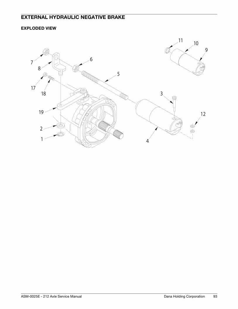
93Dana Holding CorporationASM-0025E - 212 Axle Service Manual
EXTERNAL HYDRAULIC NEGATIVE BRAKE
EXPLODED VIEW
1
2
3
4
5
9
12
1011
1718
19
678
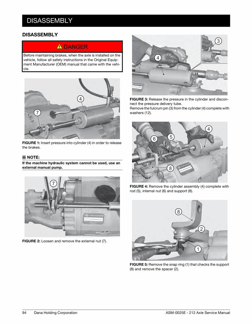
94
DISASSEMBLY
Dana Holding Corporation ASM-0025E - 212 Axle Service Manual
DISASSEMBLY
Before maintaining brakes, when the axle is installed on the vehicle, follow all safety instructions in the Original Equip-ment Manufacturer (OEM) manual that came with the vehi-cle.
FIGURE 1: Insert pressure into cylinder (4) in order to release the brakes.
NOTE:
If the machine hydraulic system cannot be used, use an
external manual pump.
FIGURE 2: Loosen and remove the external nut (7).
DANGER
7
4
7
FIGURE 3: Release the pressure in the cylinder and discon-nect the pressure delivery tube. Remove the fulcrum pin (3) from the cylinder (4) complete with washers (12).
FIGURE 4: Remove the cylinder assembly (4) complete with rod (5), internal nut (6) and support (8).
FIGURE 5: Remove the snap ring (1) that checks the support (8) and remove the spacer (2).
4
3
456
8
1
2
8
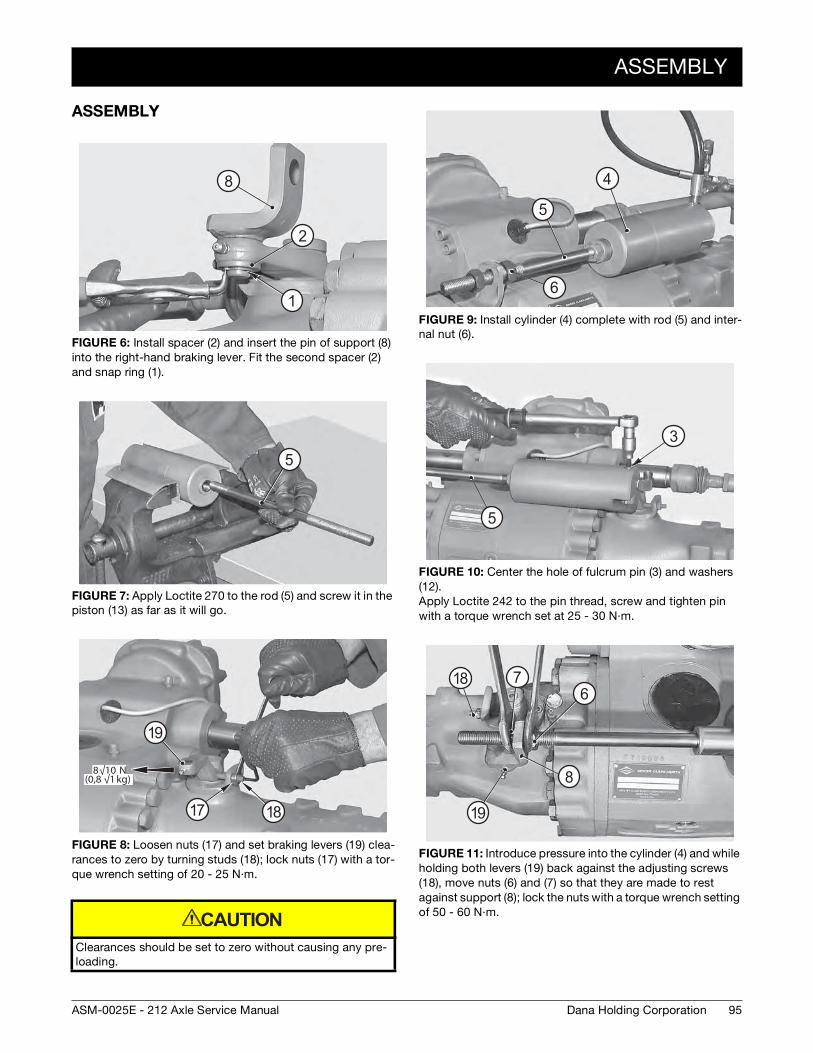
ASSEMBLY
95Dana Holding CorporationASM-0025E - 212 Axle Service Manual
ASSEMBLY
FIGURE 6: Install spacer (2) and insert the pin of support (8) into the right-hand braking lever. Fit the second spacer (2) and snap ring (1).
FIGURE 7: Apply Loctite 270 to the rod (5) and screw it in the piston (13) as far as it will go.
FIGURE 8: Loosen nuts (17) and set braking levers (19) clea-rances to zero by turning studs (18); lock nuts (17) with a tor-que wrench setting of 20 - 25 N·m.
Clearances should be set to zero without causing any pre-loading.
1
2
8
5
8√10 N(0,8 √1 kg)
19
1817
CAUTION
FIGURE 9: Install cylinder (4) complete with rod (5) and inter-nal nut (6).
FIGURE 10: Center the hole of fulcrum pin (3) and washers (12). Apply Loctite 242 to the pin thread, screw and tighten pin with a torque wrench set at 25 - 30 N·m.
FIGURE 11: Introduce pressure into the cylinder (4) and while holding both levers (19) back against the adjusting screws (18), move nuts (6) and (7) so that they are made to rest against support (8); lock the nuts with a torque wrench setting of 50 - 60 N·m.
4
6
5
5
3
67
8
19
18
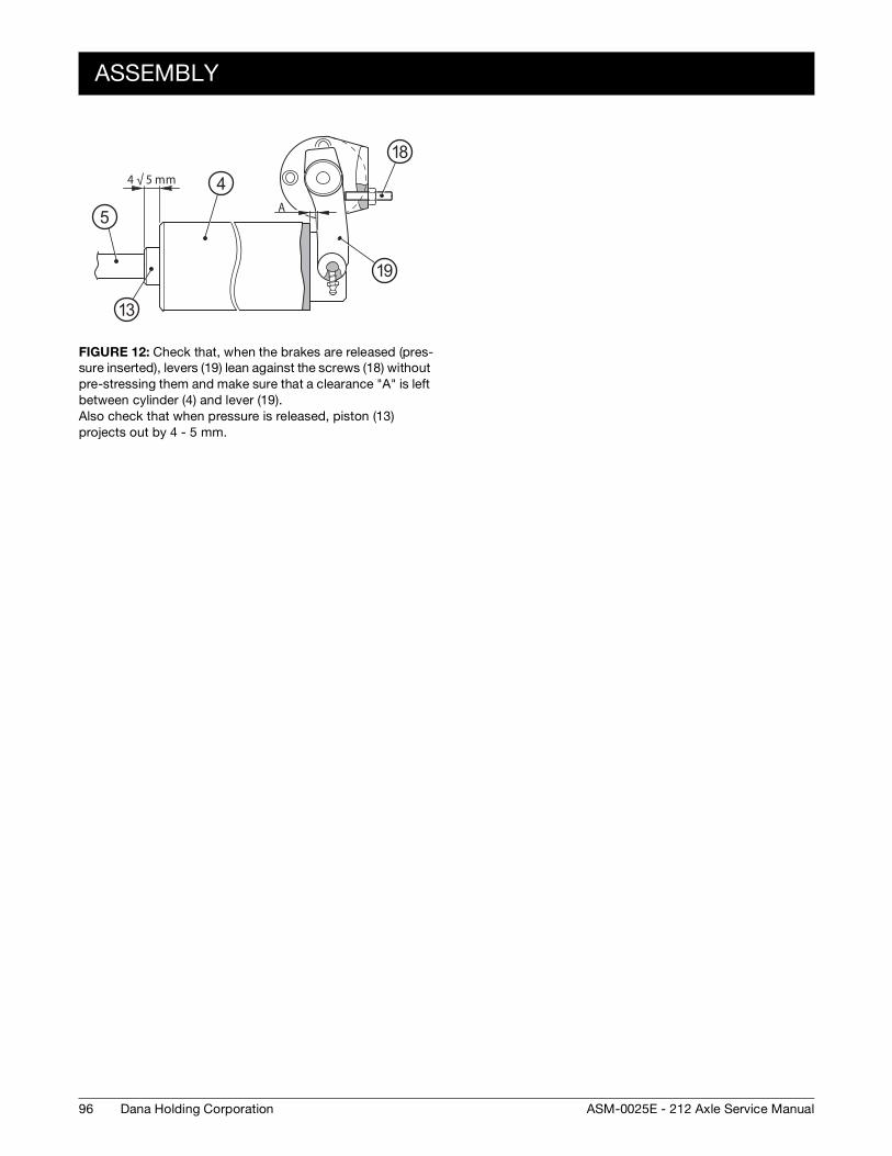
96
ASSEMBLY
Dana Holding Corporation ASM-0025E - 212 Axle Service Manual
FIGURE 12: Check that, when the brakes are released (pres-sure inserted), levers (19) lean against the screws (18) without pre-stressing them and make sure that a clearance "A" is left between cylinder (4) and lever (19). Also check that when pressure is released, piston (13) projects out by 4 - 5 mm.
A
4 √ 5 mm
5
4
18
19
13
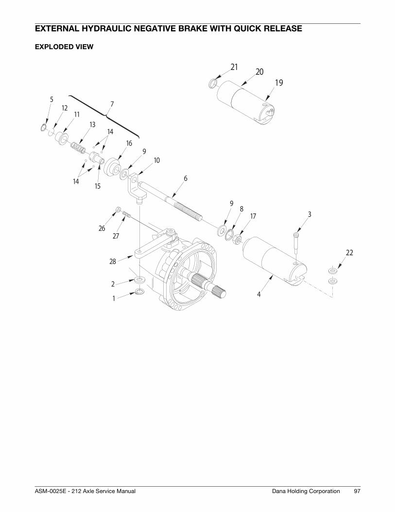
97Dana Holding CorporationASM-0025E - 212 Axle Service Manual
EXTERNAL HYDRAULIC NEGATIVE BRAKE WITH QUICK RELEASE
EXPLODED VIEW
1
2
3
4
5
6
8
910
1112
1314
15
16
17
14
9
2627
7
28
192021
22
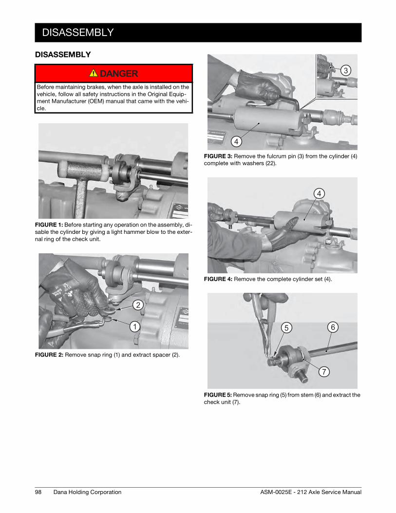
98
DISASSEMBLY
Dana Holding Corporation ASM-0025E - 212 Axle Service Manual
DISASSEMBLY
Before maintaining brakes, when the axle is installed on the vehicle, follow all safety instructions in the Original Equip-ment Manufacturer (OEM) manual that came with the vehi-cle.
FIGURE 1: Before starting any operation on the assembly, di-sable the cylinder by giving a light hammer blow to the exter-nal ring of the check unit.
FIGURE 2: Remove snap ring (1) and extract spacer (2).
DANGER
2
1
FIGURE 3: Remove the fulcrum pin (3) from the cylinder (4) complete with washers (22).
FIGURE 4: Remove the complete cylinder set (4).
FIGURE 5: Remove snap ring (5) from stem (6) and extract the check unit (7).
3
4
4
5 6
7
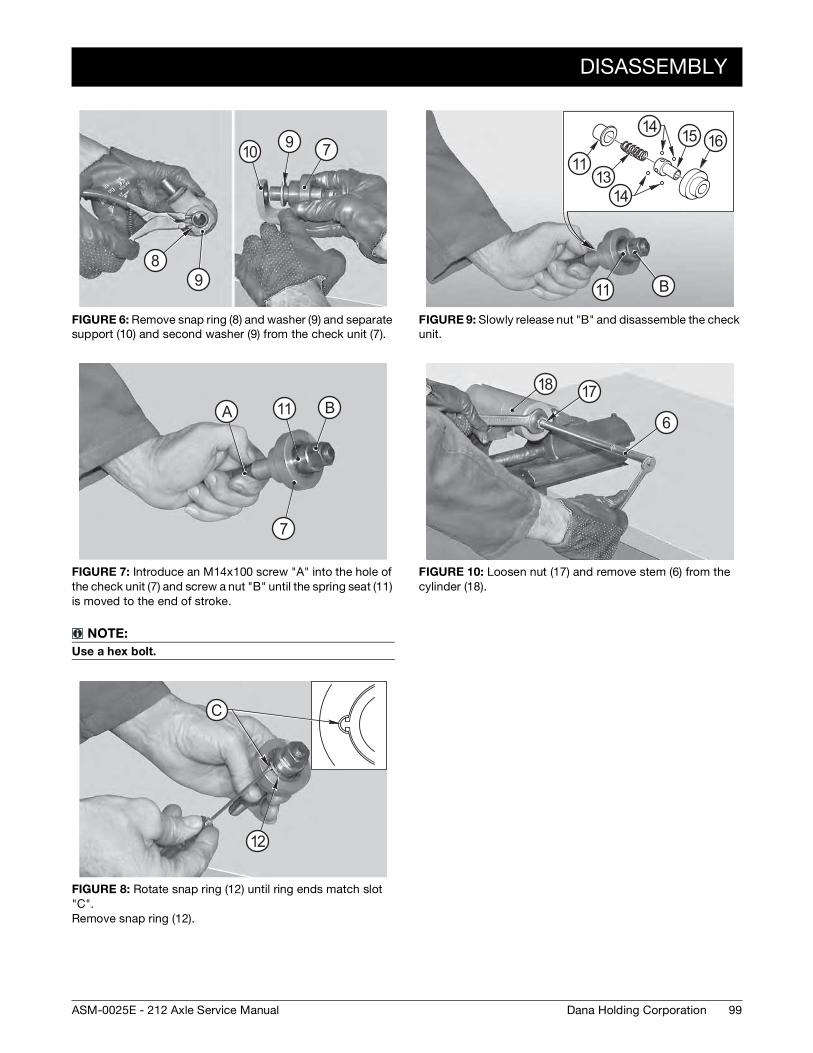
DISASSEMBLY
99Dana Holding CorporationASM-0025E - 212 Axle Service Manual
FIGURE 6: Remove snap ring (8) and washer (9) and separate support (10) and second washer (9) from the check unit (7).
FIGURE 7: Introduce an M14x100 screw "A" into the hole of the check unit (7) and screw a nut "B" until the spring seat (11) is moved to the end of stroke.
NOTE:
Use a hex bolt.
FIGURE 8: Rotate snap ring (12) until ring ends match slot "C". Remove snap ring (12).
7
89
910
BAA B
7
11
CC
12
FIGURE 9: Slowly release nut "B" and disassemble the check unit.
FIGURE 10: Loosen nut (17) and remove stem (6) from the cylinder (18).
BB11
1113
14
14 15 16
6
1718
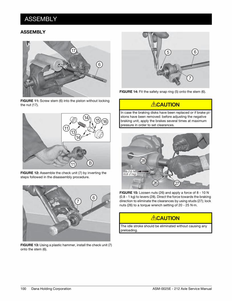
100
ASSEMBLY
Dana Holding Corporation ASM-0025E - 212 Axle Service Manual
ASSEMBLY
FIGURE 11: Screw stem (6) into the piston without locking the nut (17).
FIGURE 12: Assemble the check unit (7) by inverting the steps followed in the disassembly procedure.
FIGURE 13: Using a plastic hammer, install the check unit (7) onto the stem (6).
6
17
BB11
1113
14
14
15 16
67
FIGURE 14: Fit the safety snap ring (5) onto the stem (6).
In case the braking disks have been replaced or if brake pi-stons have been removed: before adjusting the negative braking unit, apply the brakes several times at maximum pressure in order to set clearances.
FIGURE 15: Loosen nuts (26) and apply a force of 8 - 10 N (0.8 - 1 kg) to levers (28). Direct the force towards the braking direction to eliminate the clearances by using studs (27); lock nuts (26) to a torque wrench setting of 20 - 25 N·m.
The idle stroke should be eliminated without causing any preloading.
5 6
7
CAUTION
8√10 N(0,8 √1 kg)
28
2726
CAUTION
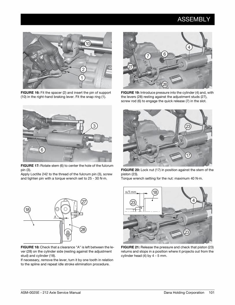
ASSEMBLY
101Dana Holding CorporationASM-0025E - 212 Axle Service Manual
FIGURE 16: Fit the spacer (2) and insert the pin of support (10) in the right-hand braking lever. Fit the snap ring (1).
FIGURE 17: Rotate stem (6) to center the hole of the fulcrum pin (3). Apply Loctite 242 to the thread of the fulcrum pin (3), screw and tighten pin with a torque wrench set to 25 - 30 N·m.
FIGURE 18: Check that a clearance "A" is left between the le-ver (28) on the cylinder side (resting against the adjustment stud) and cylinder (18). If necessary, remove the lever, turn it by one tooth in relation to the spline and repeat idle stroke elimination procedure.
2
1
10
3
6
A
28
27
18
FIGURE 19: Introduce pressure into the cylinder (4) and, with the levers (28) resting against the adjustment studs (27), screw rod (6) to engage the quick release (7) in the slot.
FIGURE 20: Lock nut (17) in position against the stem of the piston (23). Torque wrench setting for the nut: maximum 40 N·m.
FIGURE 21: Release the pressure and check that piston (23) returns and stops in a position where it projects out from the cylinder head (4) by 4 - 5 mm.
467
28
27
23
17
√ mm
4
23
18
23
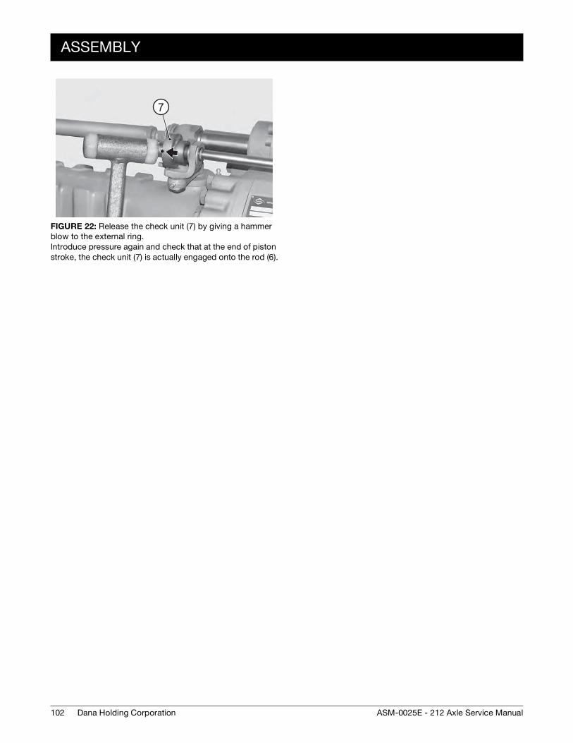
102
ASSEMBLY
Dana Holding Corporation ASM-0025E - 212 Axle Service Manual
FIGURE 22: Release the check unit (7) by giving a hammer blow to the external ring. Introduce pressure again and check that at the end of piston stroke, the check unit (7) is actually engaged onto the rod (6).
7
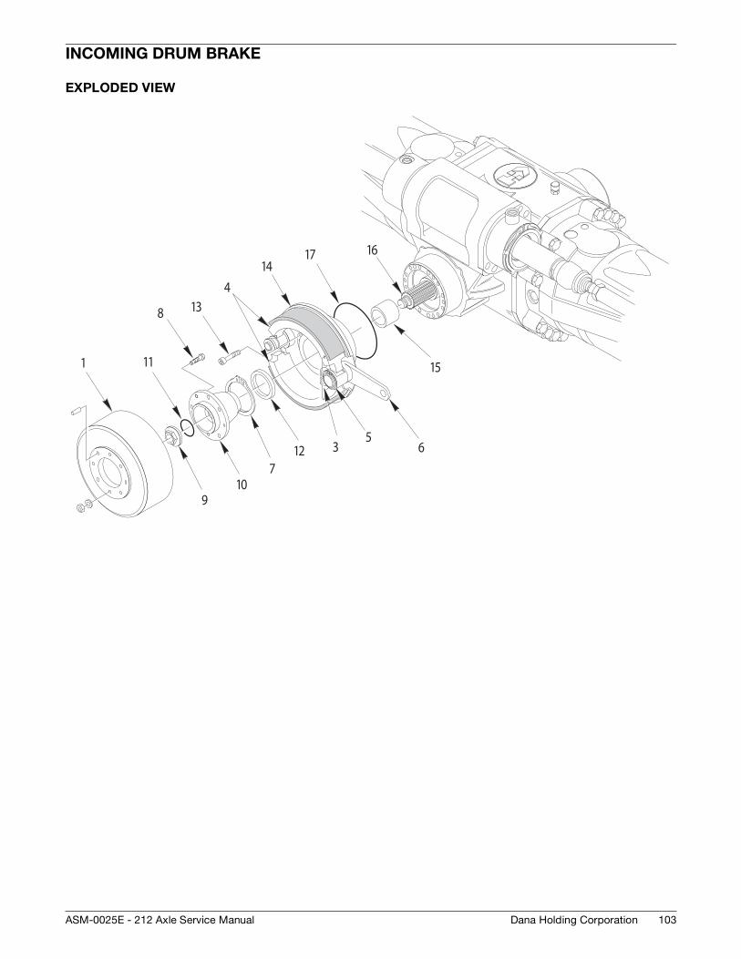
103Dana Holding CorporationASM-0025E - 212 Axle Service Manual
INCOMING DRUM BRAKE
EXPLODED VIEW
1
3
4
56
7
8
910
11
12
13
17
15
1416
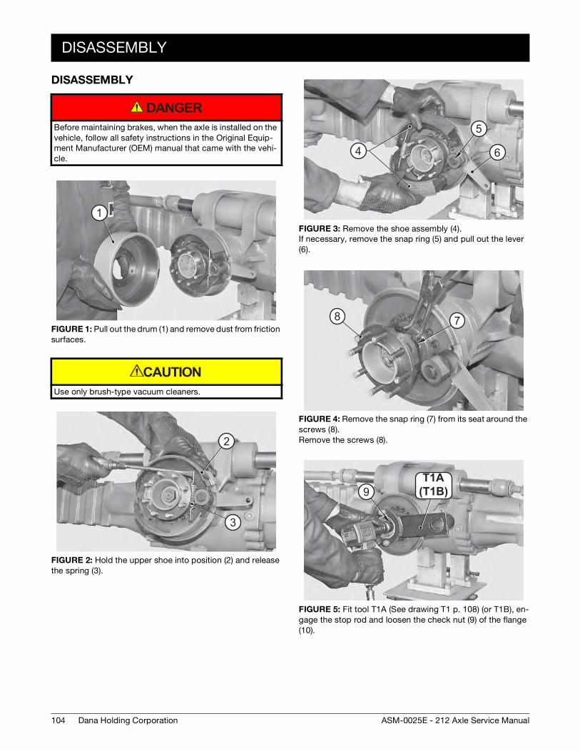
104
DISASSEMBLY
Dana Holding Corporation ASM-0025E - 212 Axle Service Manual
DISASSEMBLY
Before maintaining brakes, when the axle is installed on the vehicle, follow all safety instructions in the Original Equip-ment Manufacturer (OEM) manual that came with the vehi-cle.
FIGURE 1: Pull out the drum (1) and remove dust from friction surfaces.
Use only brush-type vacuum cleaners.
FIGURE 2: Hold the upper shoe into position (2) and release the spring (3).
DANGER
1
CAUTION
3
2
FIGURE 3: Remove the shoe assembly (4). If necessary, remove the snap ring (5) and pull out the lever (6).
FIGURE 4: Remove the snap ring (7) from its seat around the screws (8). Remove the screws (8).
FIGURE 5: Fit tool T1A (See drawing T1 p. 108) (or T1B), en-gage the stop rod and loosen the check nut (9) of the flange (10).
4
5
6
78
(T20B )T20AT1A
(T1B)9
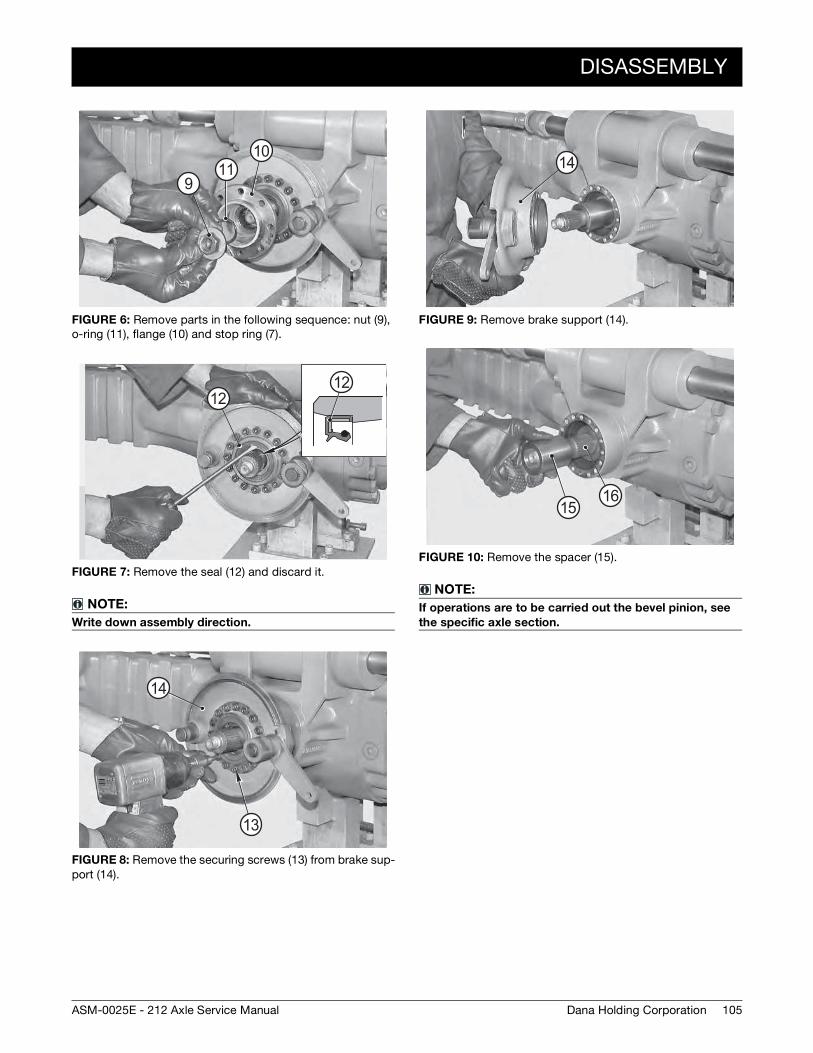
DISASSEMBLY
105Dana Holding CorporationASM-0025E - 212 Axle Service Manual
FIGURE 6: Remove parts in the following sequence: nut (9), o-ring (11), flange (10) and stop ring (7).
FIGURE 7: Remove the seal (12) and discard it.
NOTE:
Write down assembly direction.
FIGURE 8: Remove the securing screws (13) from brake sup-port (14).
9
1011
1212
14
13
FIGURE 9: Remove brake support (14).
FIGURE 10: Remove the spacer (15).
NOTE:
If operations are to be carried out the bevel pinion, see
the specific axle section.
14
1615
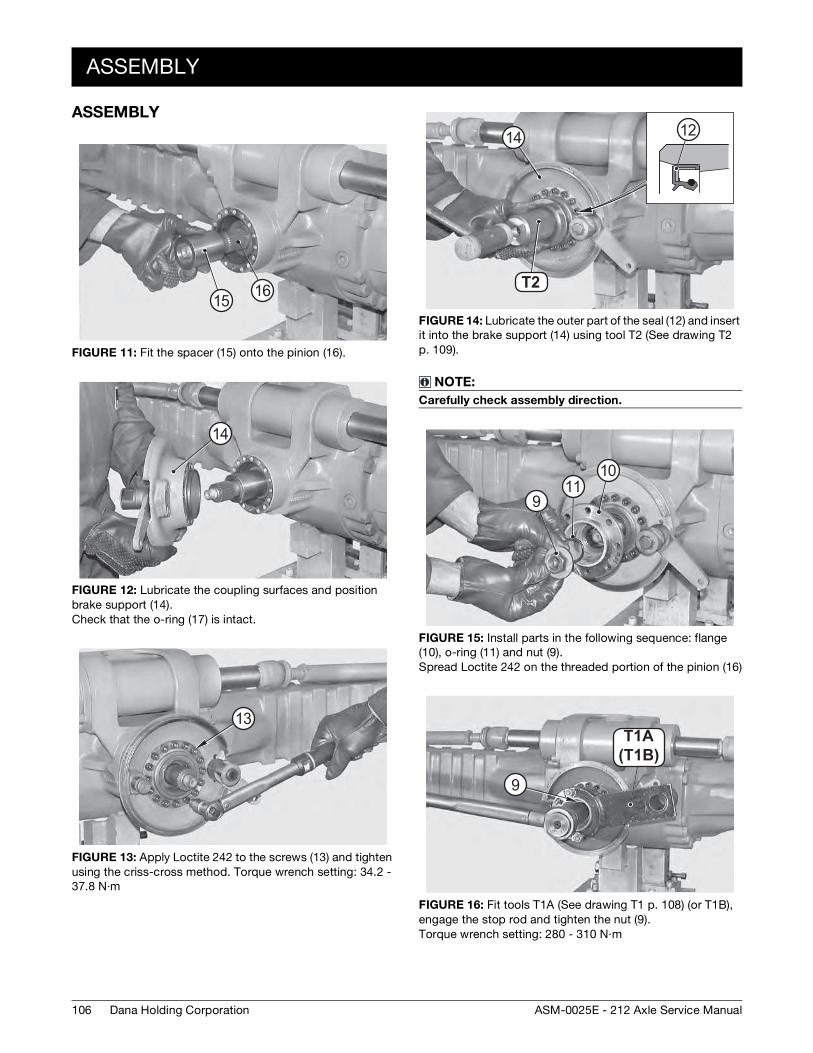
106
ASSEMBLY
Dana Holding Corporation ASM-0025E - 212 Axle Service Manual
ASSEMBLY
FIGURE 11: Fit the spacer (15) onto the pinion (16).
FIGURE 12: Lubricate the coupling surfaces and position brake support (14). Check that the o-ring (17) is intact.
FIGURE 13: Apply Loctite 242 to the screws (13) and tighten using the criss-cross method. Torque wrench setting: 34.2 - 37.8 N·m
1615
14
13
FIGURE 14: Lubricate the outer part of the seal (12) and insert it into the brake support (14) using tool T2 (See drawing T2 p. 109).
NOTE:
Carefully check assembly direction.
FIGURE 15: Install parts in the following sequence: flange (10), o-ring (11) and nut (9). Spread Loctite 242 on the threaded portion of the pinion (16)
FIGURE 16: Fit tools T1A (See drawing T1 p. 108) (or T1B), engage the stop rod and tighten the nut (9). Torque wrench setting: 280 - 310 N·m
T2 7T2
14 12
9
1011
(T20B )T20AT1A
(T1B)
9
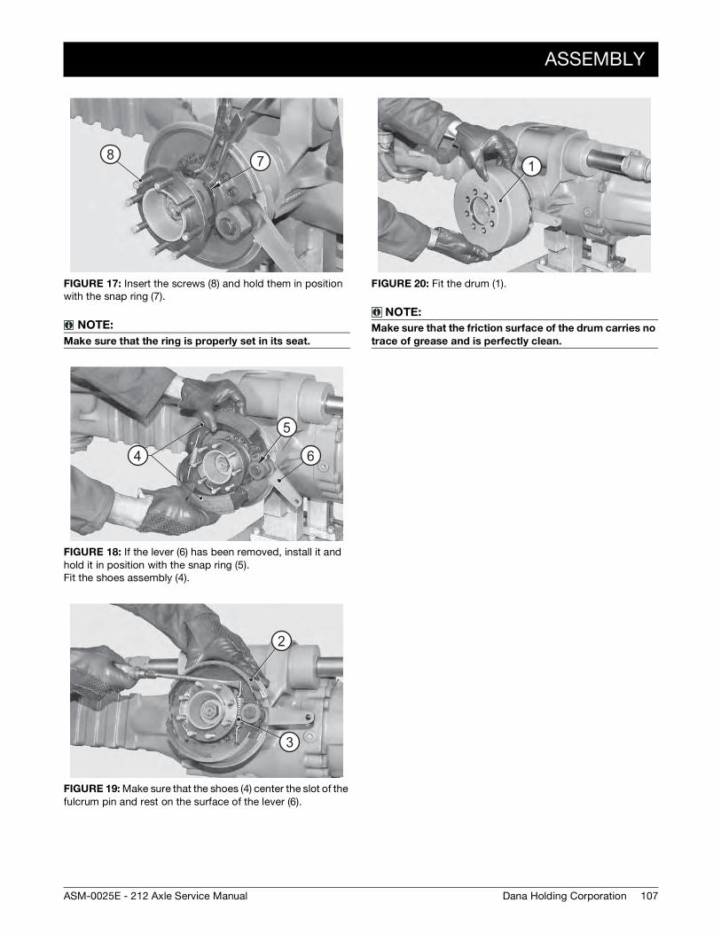
ASSEMBLY
107Dana Holding CorporationASM-0025E - 212 Axle Service Manual
FIGURE 17: Insert the screws (8) and hold them in position with the snap ring (7).
NOTE:
Make sure that the ring is properly set in its seat.
FIGURE 18: If the lever (6) has been removed, install it and hold it in position with the snap ring (5). Fit the shoes assembly (4).
FIGURE 19: Make sure that the shoes (4) center the slot of the fulcrum pin and rest on the surface of the lever (6).
78
4
5
6
2
3
FIGURE 20: Fit the drum (1).
NOTE:
Make sure that the friction surface of the drum carries no
trace of grease and is perfectly clean.
1
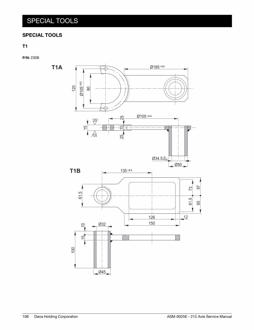
108
SPECIAL TOOLS
Dana Holding Corporation ASM-0025E - 212 Axle Service Manual
SPECIAL TOOLS
T1
P/N: 2308
80
± 0.
2Ø
105
120
15
± 0.2Ø10525
2510
Ø50
± 0.2Ø185
-- 0+ 0.2Ø34.5
125
125
61.5
100
1510
Ø45
126150
12
61.5
73 9785
135 ±0.5
Ø32
T1A
T1B
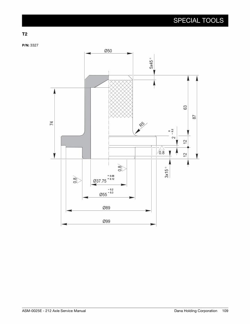
SPECIAL TOOLS
109Dana Holding CorporationASM-0025E - 212 Axle Service Manual
T2
P/N: 3327
0.8
0.8
0.8
Ø50
5x45
°
0--
0.2
12
3x15
°
1263
87
2+ 0.08+ 0.12Ø37.75
-- 0.2-- 0.3Ø55
Ø89
Ø99
R574

110
SPECIAL TOOLS
Dana Holding Corporation ASM-0025E - 212 Axle Service Manual
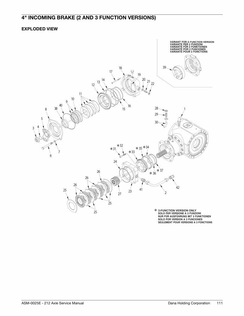
111Dana Holding CorporationASM-0025E - 212 Axle Service Manual
4" INCOMING BRAKE (2 AND 3 FUNCTION VERSIONS)
EXPLODED VIEW
RKZA 0040
1
223
24
2526
27
28
29
30
3132
33
26
26
25
25
41
3435
3637
42
39
3 4
5
7
8
910
11
1213 14
1516
1718
20 21 22
3840
6
19
FUNCTION VERSION
3-FUNCTION VERSION ONLY
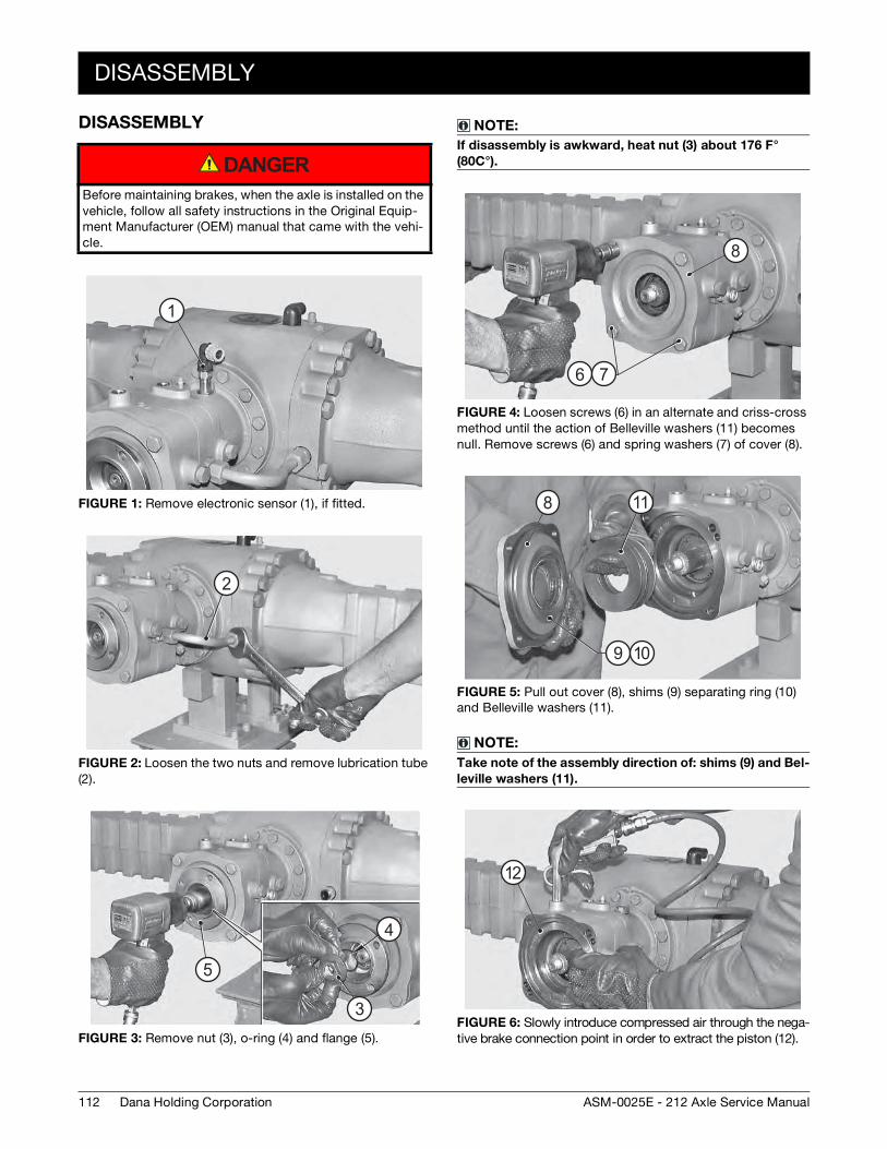
112
DISASSEMBLY
Dana Holding Corporation ASM-0025E - 212 Axle Service Manual
DISASSEMBLY
Before maintaining brakes, when the axle is installed on the vehicle, follow all safety instructions in the Original Equip-ment Manufacturer (OEM) manual that came with the vehi-cle.
FIGURE 1: Remove electronic sensor (1), if fitted.
FIGURE 2: Loosen the two nuts and remove lubrication tube (2).
FIGURE 3: Remove nut (3), o-ring (4) and flange (5).
DANGER
1
2
3
4
5
3
4
5
NOTE:
If disassembly is awkward, heat nut (3) about 176 F°
(80C°).
FIGURE 4: Loosen screws (6) in an alternate and criss-cross method until the action of Belleville washers (11) becomes null. Remove screws (6) and spring washers (7) of cover (8).
FIGURE 5: Pull out cover (8), shims (9) separating ring (10) and Belleville washers (11).
NOTE:
Take note of the assembly direction of: shims (9) and Bel-
leville washers (11).
FIGURE 6: Slowly introduce compressed air through the nega-tive brake connection point in order to extract the piston (12).
6 7
8
8
9 10
11
12
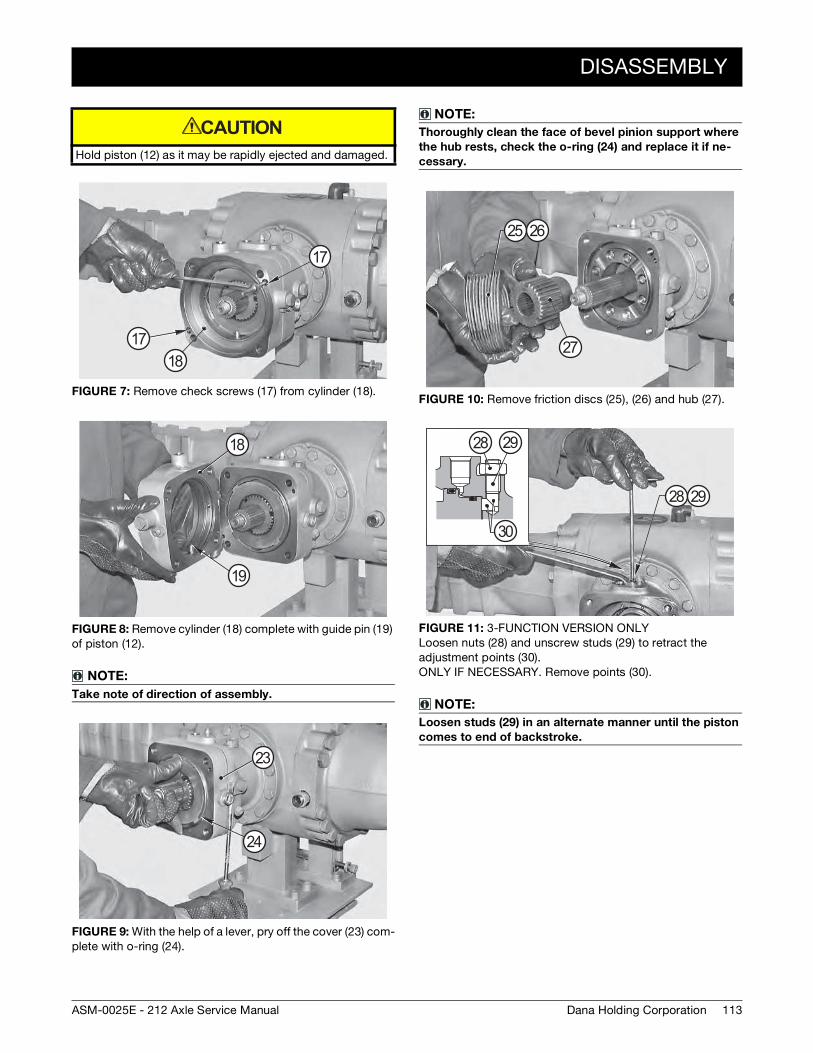
DISASSEMBLY
113Dana Holding CorporationASM-0025E - 212 Axle Service Manual
Hold piston (12) as it may be rapidly ejected and damaged.
FIGURE 7: Remove check screws (17) from cylinder (18).
FIGURE 8: Remove cylinder (18) complete with guide pin (19) of piston (12).
NOTE:
Take note of direction of assembly.
FIGURE 9: With the help of a lever, pry off the cover (23) com-plete with o-ring (24).
CAUTION
17
17
18
18
19
23
24
NOTE:
Thoroughly clean the face of bevel pinion support where
the hub rests, check the o-ring (24) and replace it if ne-
cessary.
FIGURE 10: Remove friction discs (25), (26) and hub (27).
FIGURE 11: 3-FUNCTION VERSION ONLY Loosen nuts (28) and unscrew studs (29) to retract the adjustment points (30). ONLY IF NECESSARY. Remove points (30).
NOTE:
Loosen studs (29) in an alternate manner until the piston
comes to end of backstroke.
25 26
27
28 29
30
28 29
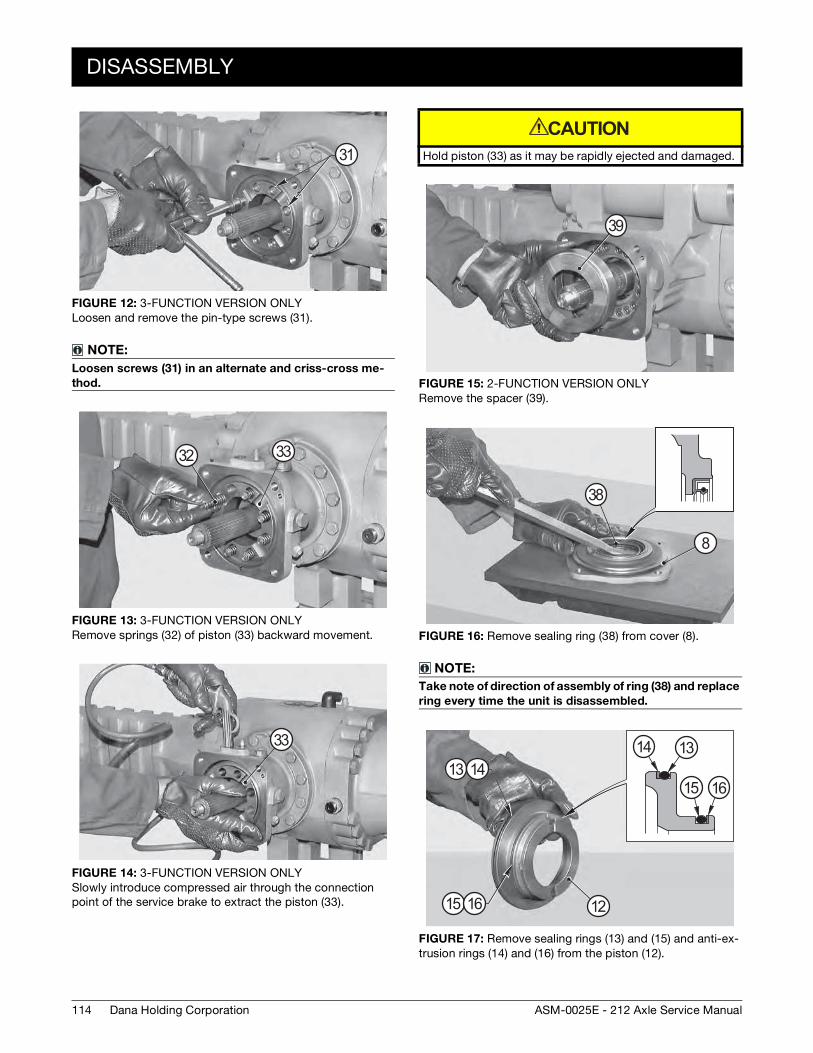
114
DISASSEMBLY
Dana Holding Corporation ASM-0025E - 212 Axle Service Manual
FIGURE 12: 3-FUNCTION VERSION ONLY Loosen and remove the pin-type screws (31).
NOTE:
Loosen screws (31) in an alternate and criss-cross me-
thod.
FIGURE 13: 3-FUNCTION VERSION ONLY Remove springs (32) of piston (33) backward movement.
FIGURE 14: 3-FUNCTION VERSION ONLY Slowly introduce compressed air through the connection point of the service brake to extract the piston (33).
31
32 33
33
Hold piston (33) as it may be rapidly ejected and damaged.
FIGURE 15: 2-FUNCTION VERSION ONLY Remove the spacer (39).
FIGURE 16: Remove sealing ring (38) from cover (8).
NOTE:
Take note of direction of assembly of ring (38) and replace
ring every time the unit is disassembled.
FIGURE 17: Remove sealing rings (13) and (15) and anti-ex-trusion rings (14) and (16) from the piston (12).
CAUTION
39
8
38
12
1314
15 16
15 16
13 14
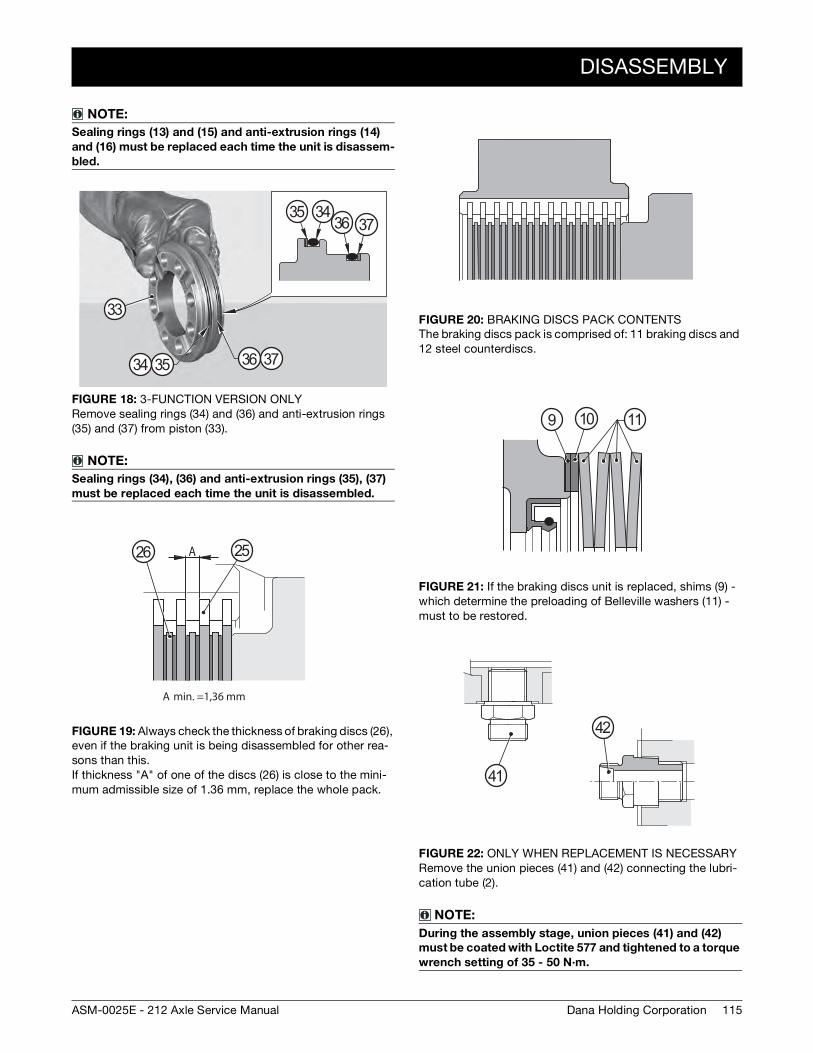
DISASSEMBLY
115Dana Holding CorporationASM-0025E - 212 Axle Service Manual
NOTE:
Sealing rings (13) and (15) and anti-extrusion rings (14)
and (16) must be replaced each time the unit is disassem-
bled.
FIGURE 18: 3-FUNCTION VERSION ONLY Remove sealing rings (34) and (36) and anti-extrusion rings (35) and (37) from piston (33).
NOTE:
Sealing rings (34), (36) and anti-extrusion rings (35), (37)
must be replaced each time the unit is disassembled.
FIGURE 19: Always check the thickness of braking discs (26), even if the braking unit is being disassembled for other rea-sons than this. If thickness "A" of one of the discs (26) is close to the mini-mum admissible size of 1.36 mm, replace the whole pack.
33
34 35 36 37
3436 37
35
A
A min. =1,36 mm
2526
FIGURE 20: BRAKING DISCS PACK CONTENTS The braking discs pack is comprised of: 11 braking discs and 12 steel counterdiscs.
FIGURE 21: If the braking discs unit is replaced, shims (9) - which determine the preloading of Belleville washers (11) - must to be restored.
FIGURE 22: ONLY WHEN REPLACEMENT IS NECESSARY Remove the union pieces (41) and (42) connecting the lubri-cation tube (2).
NOTE:
During the assembly stage, union pieces (41) and (42)
must be coated with Loctite 577 and tightened to a torque
wrench setting of 35 - 50 N·m.
9 10 11
42
41
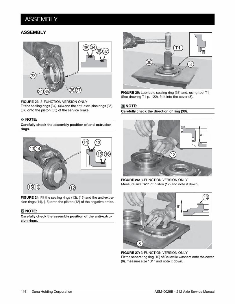
116
ASSEMBLY
Dana Holding Corporation ASM-0025E - 212 Axle Service Manual
ASSEMBLY
FIGURE 23: 3-FUNCTION VERSION ONLY Fit the sealing rings (34), (36) and the anti-extrusion rings (35), (37) onto the piston (33) of the service brake.
NOTE:
Carefully check the assembly position of anti-extrusion
rings.
FIGURE 24: Fit the sealing rings (13), (15) and the anti-extru-sion rings (14), (16) onto the piston (12) of the negative brake.
NOTE:
Carefully check the assembly position of the anti-extru-
sion rings.
34
33
35 36 37
35 3436 37
12
13 14
15 16
1314
15 16
FIGURE 25: Lubricate sealing ring (38) and, using tool T1 (See drawing T1 p. 122), fit it into the cover (8).
NOTE:
Carefully check the direction of ring (38).
FIGURE 26: 3-FUNCTION VERSION ONLY Measure size "A1" of piston (12) and note it down.
FIGURE 27: 3-FUNCTION VERSION ONLY Fit the separating ring (10) of Belleville washers onto the cover (8), measure size "B1" and note it down.
T3 1T1
838
A1
12
B1
8
10
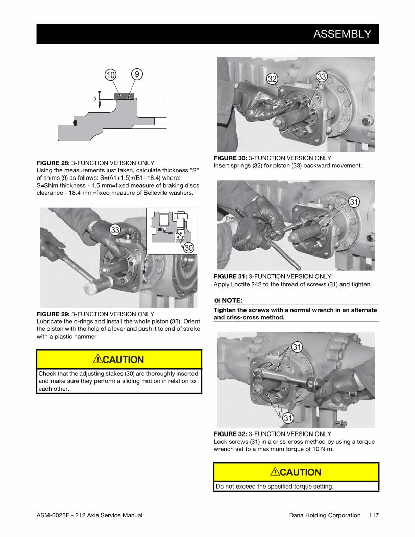
ASSEMBLY
117Dana Holding CorporationASM-0025E - 212 Axle Service Manual
FIGURE 28: 3-FUNCTION VERSION ONLY Using the measurements just taken, calculate thickness "S" of shims (9) as follows: S=(A1+1.5)±(B1+18.4) where: S=Shim thickness - 1.5 mm=fixed measure of braking discs clearance - 18.4 mm=fixed measure of Belleville washers.
FIGURE 29: 3-FUNCTION VERSION ONLY Lubricate the o-rings and install the whole piston (33). Orient the piston with the help of a lever and push it to end of stroke with a plastic hammer.
Check that the adjusting stakes (30) are thoroughly inserted and make sure they perform a sliding motion in relation to each other.
S
910
30
33
CAUTION
FIGURE 30: 3-FUNCTION VERSION ONLY Insert springs (32) for piston (33) backward movement.
FIGURE 31: 3-FUNCTION VERSION ONLY Apply Loctite 242 to the thread of screws (31) and tighten.
NOTE:
Tighten the screws with a normal wrench in an alternate
and criss-cross method.
FIGURE 32: 3-FUNCTION VERSION ONLY Lock screws (31) in a criss-cross method by using a torque wrench set to a maximum torque of 10 N·m.
Do not exceed the specified torque setting.
3332
31
31
31
CAUTION
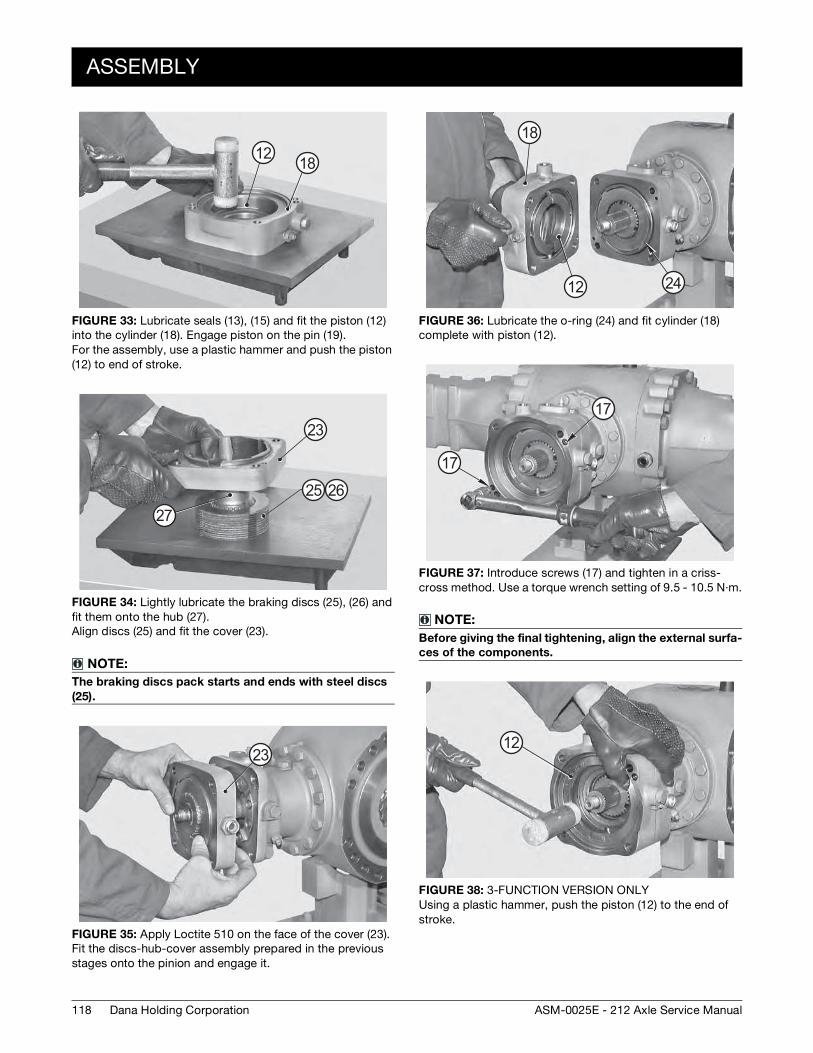
118
ASSEMBLY
Dana Holding Corporation ASM-0025E - 212 Axle Service Manual
FIGURE 33: Lubricate seals (13), (15) and fit the piston (12) into the cylinder (18). Engage piston on the pin (19). For the assembly, use a plastic hammer and push the piston (12) to end of stroke.
FIGURE 34: Lightly lubricate the braking discs (25), (26) and fit them onto the hub (27). Align discs (25) and fit the cover (23).
NOTE:
The braking discs pack starts and ends with steel discs
(25).
FIGURE 35: Apply Loctite 510 on the face of the cover (23). Fit the discs-hub-cover assembly prepared in the previous stages onto the pinion and engage it.
12 18
27
23
25 26
23
FIGURE 36: Lubricate the o-ring (24) and fit cylinder (18) complete with piston (12).
FIGURE 37: Introduce screws (17) and tighten in a criss-cross method. Use a torque wrench setting of 9.5 - 10.5 N·m.
NOTE:
Before giving the final tightening, align the external surfa-
ces of the components.
FIGURE 38: 3-FUNCTION VERSION ONLY Using a plastic hammer, push the piston (12) to the end of stroke.
18
12 24
17
17
12
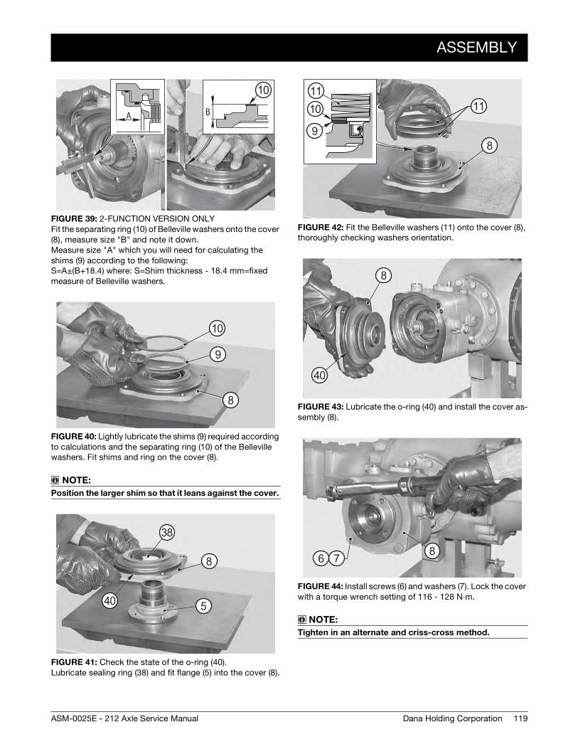
ASSEMBLY
119Dana Holding CorporationASM-0025E - 212 Axle Service Manual
FIGURE 39: 2-FUNCTION VERSION ONLY Fit the separating ring (10) of Belleville washers onto the cover (8), measure size "B" and note it down. Measure size "A" which you will need for calculating the shims (9) according to the following: S=A±(B+18.4) where: S=Shim thickness - 18.4 mm=fixed measure of Belleville washers.
FIGURE 40: Lightly lubricate the shims (9) required according to calculations and the separating ring (10) of the Belleville washers. Fit shims and ring on the cover (8).
NOTE:
Position the larger shim so that it leans against the cover.
FIGURE 41: Check the state of the o-ring (40). Lubricate sealing ring (38) and fit flange (5) into the cover (8).
A B
10
8
9
10
5
8
38
40
FIGURE 42: Fit the Belleville washers (11) onto the cover (8), thoroughly checking washers orientation.
FIGURE 43: Lubricate the o-ring (40) and install the cover as-sembly (8).
FIGURE 44: Install screws (6) and washers (7). Lock the cover with a torque wrench setting of 116 - 128 N·m.
NOTE:
Tighten in an alternate and criss-cross method.
98
1011
11
8
40
86 7
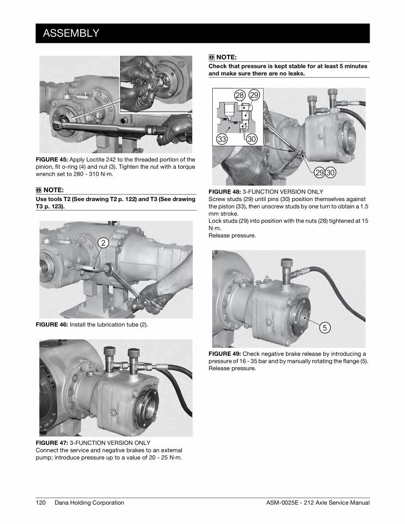
120
ASSEMBLY
Dana Holding Corporation ASM-0025E - 212 Axle Service Manual
FIGURE 45: Apply Loctite 242 to the threaded portion of the pinion, fit o-ring (4) and nut (3). Tighten the nut with a torque wrench set to 280 - 310 N·m.
NOTE:
Use tools T2 (See drawing T2 p. 122) and T3 (See drawing
T3 p. 123).
FIGURE 46: Install the lubrication tube (2).
FIGURE 47: 3-FUNCTION VERSION ONLY Connect the service and negative brakes to an external pump; introduce pressure up to a value of 20 - 25 N·m.
2
NOTE:
Check that pressure is kept stable for at least 5 minutes
and make sure there are no leaks.
FIGURE 48: 3-FUNCTION VERSION ONLY Screw studs (29) until pins (30) position themselves against the piston (33), then unscrew studs by one turn to obtain a 1.5 mm stroke. Lock studs (29) into position with the nuts (28) tightened at 15 N·m. Release pressure.
FIGURE 49: Check negative brake release by introducing a pressure of 16 - 35 bar and by manually rotating the flange (5). Release pressure.
29
29 30
28
3033
5
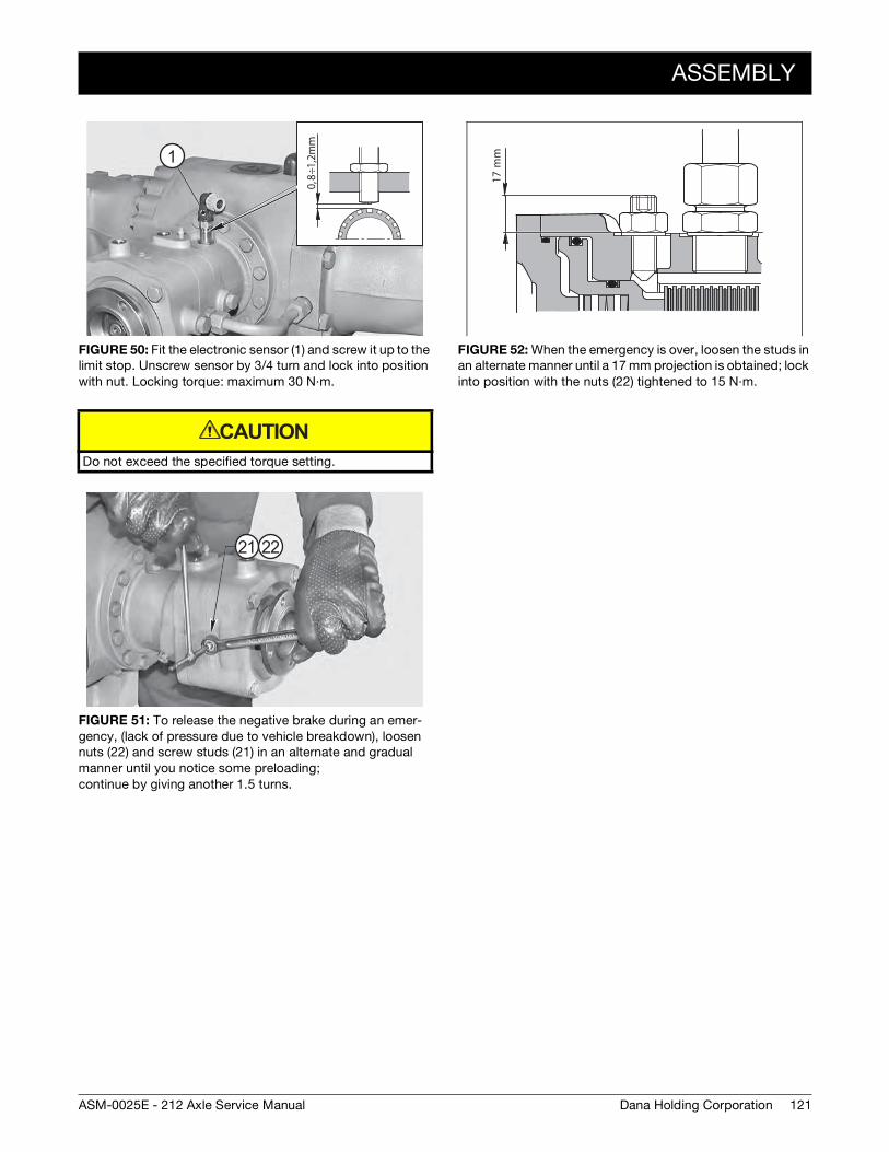
ASSEMBLY
121Dana Holding CorporationASM-0025E - 212 Axle Service Manual
FIGURE 50: Fit the electronic sensor (1) and screw it up to the limit stop. Unscrew sensor by 3/4 turn and lock into position with nut. Locking torque: maximum 30 N·m.
Do not exceed the specified torque setting.
FIGURE 51: To release the negative brake during an emer-gency, (lack of pressure due to vehicle breakdown), loosen nuts (22) and screw studs (21) in an alternate and gradual manner until you notice some preloading; continue by giving another 1.5 turns.
0,8÷
1,2m
m
1
CAUTION
21 22
FIGURE 52: When the emergency is over, loosen the studs in an alternate manner until a 17 mm projection is obtained; lock into position with the nuts (22) tightened to 15 N·m.
17 m
m
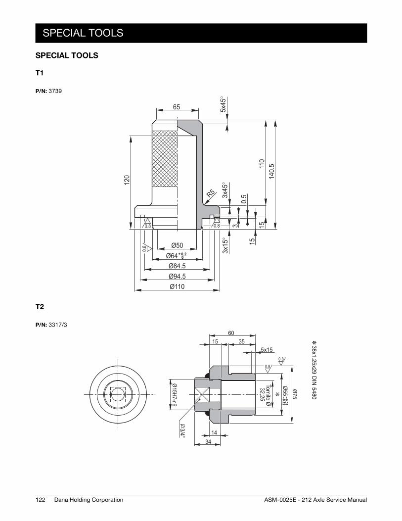
122
SPECIAL TOOLS
Dana Holding Corporation ASM-0025E - 212 Axle Service Manual
SPECIAL TOOLS
T1
T2
P/N: 3739
0.8
0.8
0.8
Ø50
3x15
°3x
45°
5x45
°
R5
Ø64Ø84.5Ø94.5Ø110
+ 0.20
110
120 14
0.5
1530.
515
65
P/N: 3317/3
0.8
0.8
3/4"Ø
15H7-n6
– 0.08– 0.12
Ø55Ø
75
35x155
6015
1434
Tornito Ø32,25
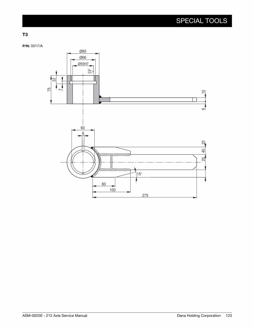
SPECIAL TOOLS
123Dana Holding CorporationASM-0025E - 212 Axle Service Manual
T3
P/N: 3317/A
0.8
Ø85
Ø55H77
60
Ø6622
75 1002
0402
6
6
60100
275
15°

124
SPECIAL TOOLS
Dana Holding Corporation ASM-0025E - 212 Axle Service Manual
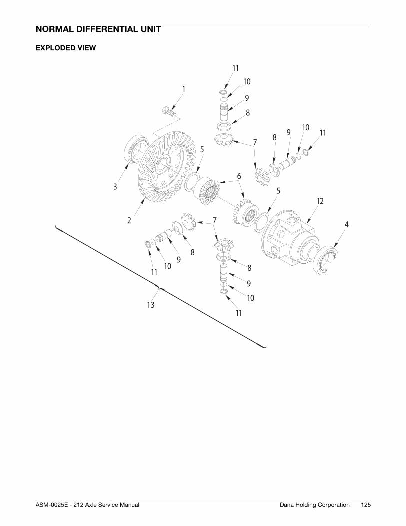
125Dana Holding CorporationASM-0025E - 212 Axle Service Manual
NORMAL DIFFERENTIAL UNIT
EXPLODED VIEW
3
4
1
2
5
6
12
11
9
7
8
10
5
98
10
11
9
9
7
8
10
11
1110
8
13
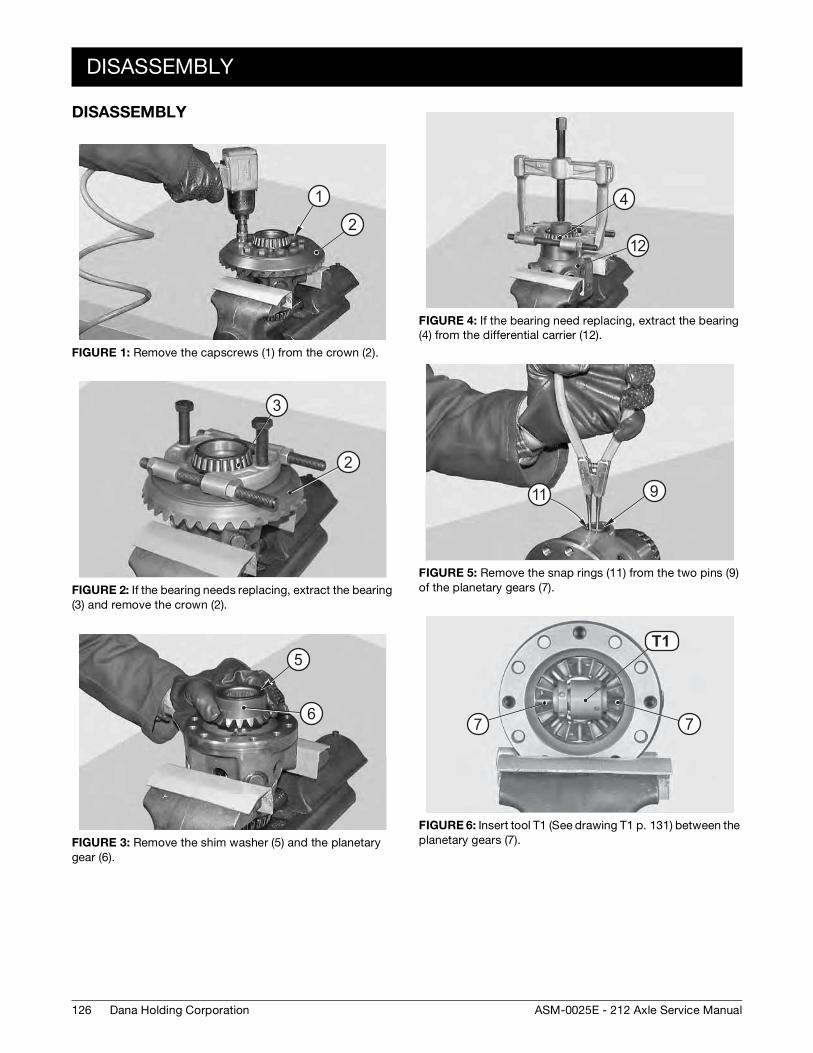
126
DISASSEMBLY
Dana Holding Corporation ASM-0025E - 212 Axle Service Manual
DISASSEMBLY
FIGURE 1: Remove the capscrews (1) from the crown (2).
FIGURE 2: If the bearing needs replacing, extract the bearing (3) and remove the crown (2).
FIGURE 3: Remove the shim washer (5) and the planetary gear (6).
��
��
1
2
��
�
2
3
��
��5
6
FIGURE 4: If the bearing need replacing, extract the bearing (4) from the differential carrier (12).
FIGURE 5: Remove the snap rings (11) from the two pins (9) of the planetary gears (7).
FIGURE 6: Insert tool T1 (See drawing T1 p. 131) between the planetary gears (7).
��
�4
12
����11 9
T1 4T1
7 7
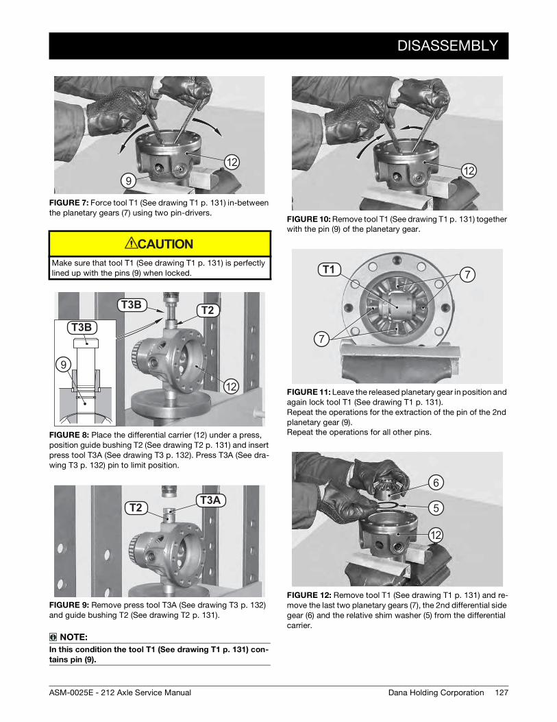
DISASSEMBLY
127Dana Holding CorporationASM-0025E - 212 Axle Service Manual
FIGURE 7: Force tool T1 (See drawing T1 p. 131) in-between the planetary gears (7) using two pin-drivers.
Make sure that tool T1 (See drawing T1 p. 131) is perfectly lined up with the pins (9) when locked.
FIGURE 8: Place the differential carrier (12) under a press, position guide bushing T2 (See drawing T2 p. 131) and insert press tool T3A (See drawing T3 p. 132). Press T3A (See dra-wing T3 p. 132) pin to limit position.
FIGURE 9: Remove press tool T3A (See drawing T3 p. 132) and guide bushing T2 (See drawing T2 p. 131).
NOTE:
In this condition the tool T1 (See drawing T1 p. 131) con-
tains pin (9).
��
��
12
9
CAUTION
T16BT1 5
T16B
T2T3B
T3B
12
9
T16AT1 5T2 T3A
FIGURE 10: Remove tool T1 (See drawing T1 p. 131) together with the pin (9) of the planetary gear.
FIGURE 11: Leave the released planetary gear in position and again lock tool T1 (See drawing T1 p. 131). Repeat the operations for the extraction of the pin of the 2nd planetary gear (9). Repeat the operations for all other pins.
FIGURE 12: Remove tool T1 (See drawing T1 p. 131) and re-move the last two planetary gears (7), the 2nd differential side gear (6) and the relative shim washer (5) from the differential carrier.
��12
T1 4T1
7
7
��
��
��
5
6
12
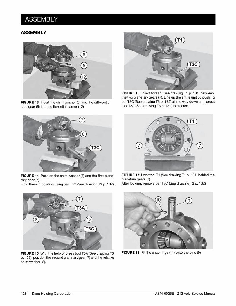
128
ASSEMBLY
Dana Holding Corporation ASM-0025E - 212 Axle Service Manual
ASSEMBLY
FIGURE 13: Insert the shim washer (5) and the differential side gear (6) in the differential carrier (12).
FIGURE 14: Position the shim washer (8) and the first plane-tary gear (7). Hold them in position using bar T3C (See drawing T3 p. 132).
FIGURE 15: With the help of press tool T3A (See drawing T3 p. 132), position the second planetary gear (7) and the relative shim washer (8).
��
��
��
65
6
12
T16CT3C
7
8
T16A
T1 6C
T3A
T3C
12
7
8
FIGURE 16: Insert tool T1 (See drawing T1 p. 131) between the two planetary gears (7). Line up the entire unit by pushing bar T3C (See drawing T3 p. 132) all the way down until press tool T3A (See drawing T3 p. 132) is ejected.
FIGURE 17: Lock tool T1 (See drawing T1 p. 131) behind the planetary gears (7). After locking, remove bar T3C (See drawing T3 p. 132).
FIGURE 18: Fit the snap rings (11) onto the pins (9).
T16C
T1 4T1
T3C
T1 4T1
77
���� 910
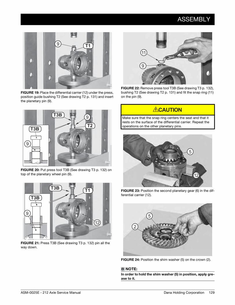
ASSEMBLY
129Dana Holding CorporationASM-0025E - 212 Axle Service Manual
FIGURE 19: Place the differential carrier (12) under the press, position guide bushing T2 (See drawing T2 p. 131) and insert the planetary pin (9).
FIGURE 20: Put press tool T3B (See drawing T3 p. 132) on top of the planetary wheel pin (9).
FIGURE 21: Press T3B (See drawing T3 p. 132) pin all the way down.
T1 5T19
T1 5
T16B
T16BT2
T3B
T3B
9
9
T16BT1 5
T16B
T1T3B
T3B
12
9
FIGURE 22: Remove press tool T3B (See drawing T3 p. 132), bushing T2 (See drawing T2 p. 131) and fit the snap ring (11) on the pin (9).
Make sure that the snap ring centers the seat and that it rests on the surface of the differential carrier. Repeat the operations on the other planetary pins.
FIGURE 23: Position the second planetary gear (6) in the dif-ferential carrier (12).
FIGURE 24: Position the shim washer (5) on the crown (2).
NOTE:
In order to hold the shim washer (5) in position, apply gre-
ase to it.
��
��
11
9
CAUTION
��
��
5
12
��
��2
5
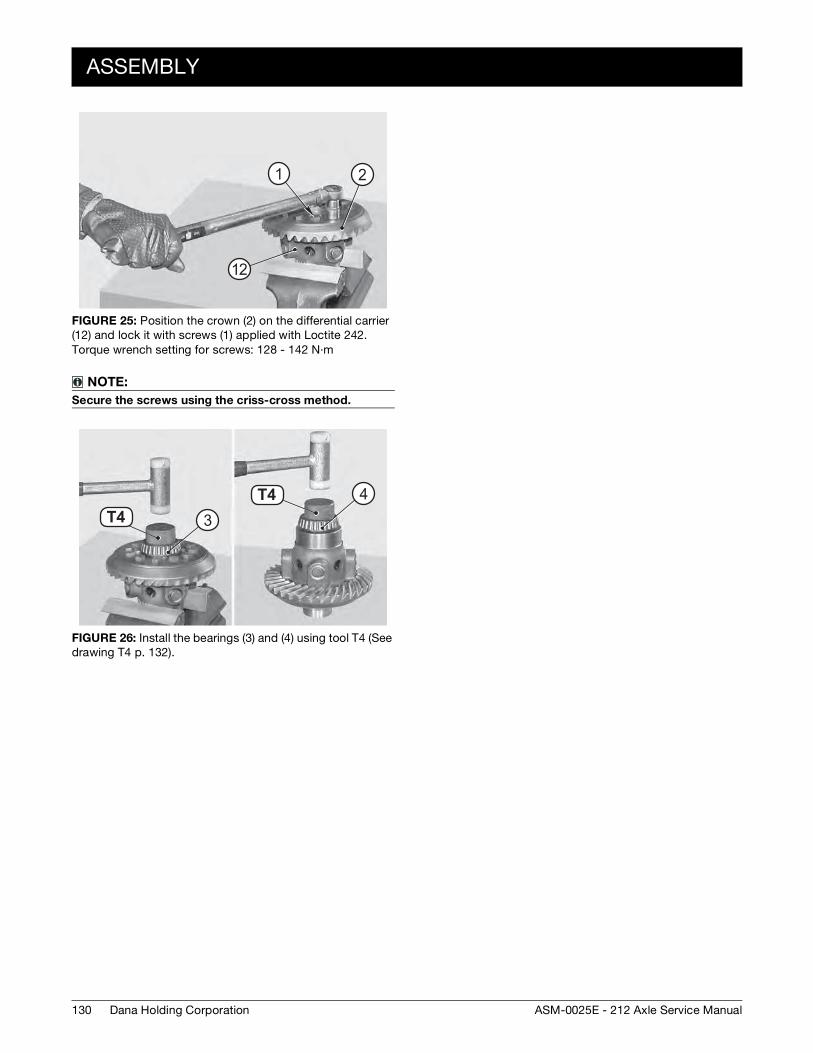
130
ASSEMBLY
Dana Holding Corporation ASM-0025E - 212 Axle Service Manual
FIGURE 25: Position the crown (2) on the differential carrier (12) and lock it with screws (1) applied with Loctite 242. Torque wrench setting for screws: 128 - 142 N·m
NOTE:
Secure the screws using the criss-cross method.
FIGURE 26: Install the bearings (3) and (4) using tool T4 (See drawing T4 p. 132).
1 2
12
T1 7
T1 7
T4T4
34
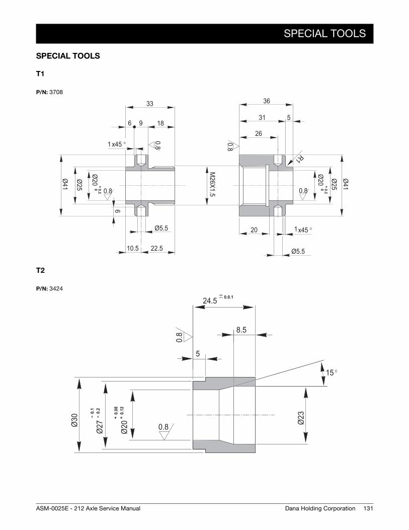
SPECIAL TOOLS
131Dana Holding CorporationASM-0025E - 212 Axle Service Manual
SPECIAL TOOLS
T1
T2
P/N: 3708
0.8
0.8
0.80.8
x45 °1
Ø41
Ø25
Ø20
+0.20
2618
36
5
20
Ø5.5
R1
M26X1.5
96
33
Ø25
Ø41
Ø20
+ 0.20
6
Ø5.5
22.510.5
x45 °1
31
P/N: 3424
0.8
0.8Ø30 --
0.1
-- 0
.2Ø
27
+ 0
.08
+ 0
.12
Ø20
5
8.5
24.5 0.0.1Ø
23
15 °
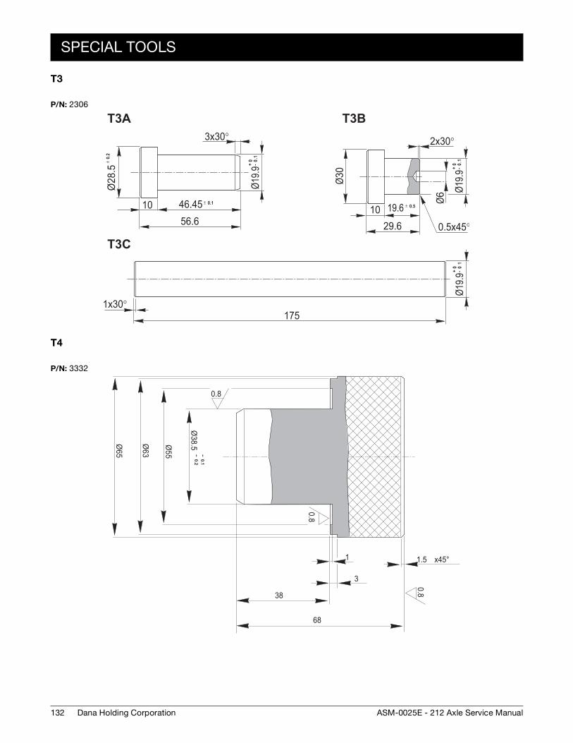
132
SPECIAL TOOLS
Dana Holding Corporation ASM-0025E - 212 Axle Service Manual
T3
T4
P/N: 23065.82
Ø
46.451056.6
x30°3
9.91Ø Ø03
2x30°
1029.6
Ø6
19.6
x45°0.5
x30°1175
9.91Ø9.91Ø
T3A
T3C
T3B
+0 -
1.0 ± 0.
2
± 0.5± 0.1
+0 -
10
+0
-1.0
P/N: 3332
0.8
0.8
0.8
-- 0.1-- 0.2
Ø38.5Ø
55
Ø63
Ø65
38
68
3
1 x45°1.5
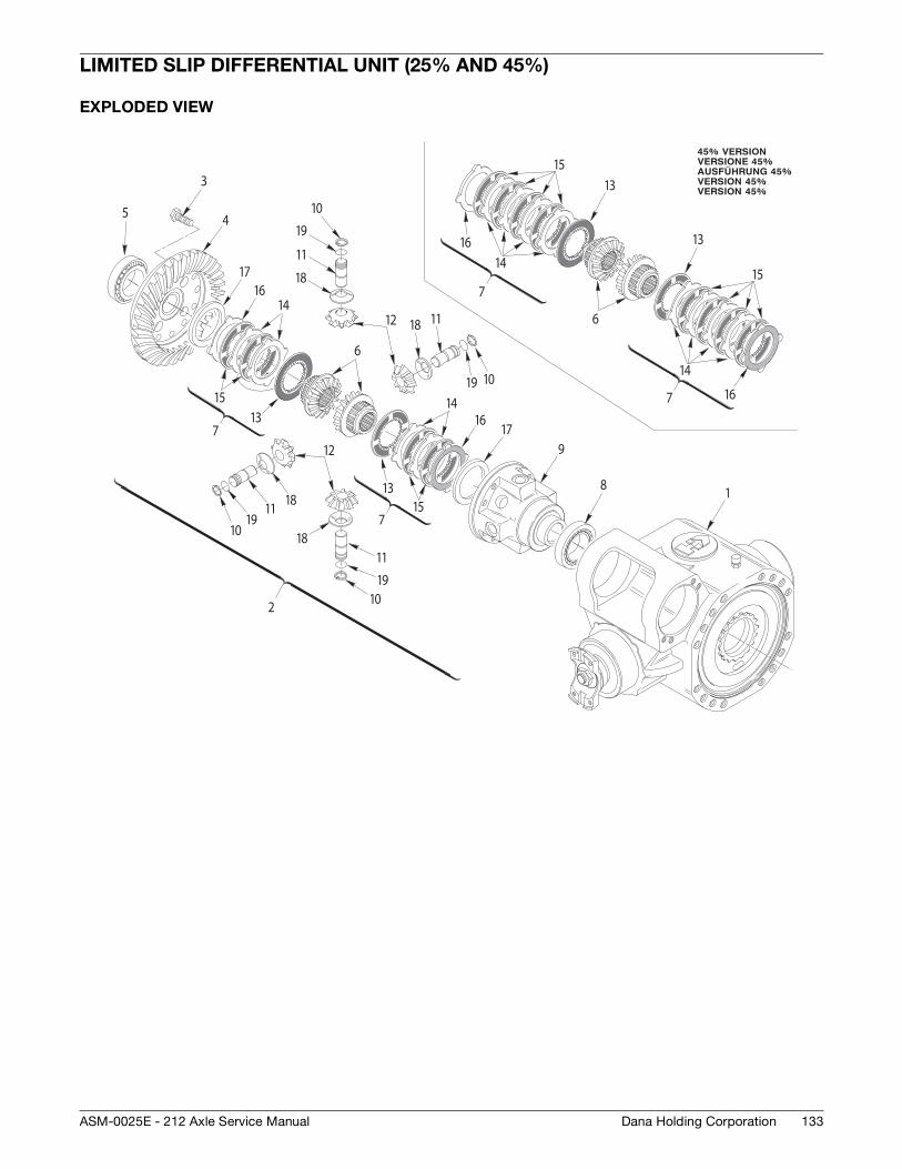
133Dana Holding CorporationASM-0025E - 212 Axle Service Manual
LIMITED SLIP DIFFERENTIAL UNIT (25% AND 45%)
EXPLODED VIEW
1
2
3
45
6
8
9
10
11
12
15
18
19
181119
10
1019
14
17
713
11
18
1019
111812
16
1614
17
1315
7
1315
1416
715
13
16
14
6
7
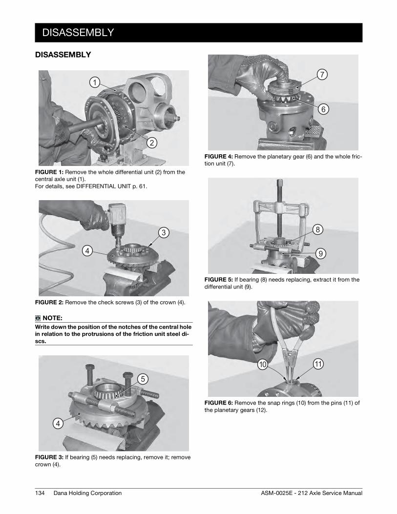
134
DISASSEMBLY
Dana Holding Corporation ASM-0025E - 212 Axle Service Manual
DISASSEMBLY
FIGURE 1: Remove the whole differential unit (2) from the central axle unit (1). For details, see DIFFERENTIAL UNIT p. 61.
FIGURE 2: Remove the check screws (3) of the crown (4).
NOTE:
Write down the position of the notches of the central hole
in relation to the protrusions of the friction unit steel di-
scs.
FIGURE 3: If bearing (5) needs replacing, remove it; remove crown (4).
1
2
4
3
5
4
FIGURE 4: Remove the planetary gear (6) and the whole fric-tion unit (7).
FIGURE 5: If bearing (8) needs replacing, extract it from the differential unit (9).
FIGURE 6: Remove the snap rings (10) from the pins (11) of the planetary gears (12).
6
7
8
9
1110
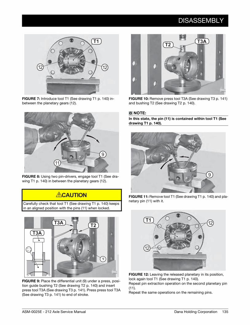
DISASSEMBLY
135Dana Holding CorporationASM-0025E - 212 Axle Service Manual
FIGURE 7: Introduce tool T1 (See drawing T1 p. 140) in-between the planetary gears (12).
FIGURE 8: Using two pin-drivers, engage tool T1 (See dra-wing T1 p. 140) in between the planetary gears (12).
Carefully check that tool T1 (See drawing T1 p. 140) keeps in an aligned position with the pins (11) when locked.
FIGURE 9: Place the differential unit (9) under a press, posi-tion guide bushing T2 (See drawing T2 p. 140) and insert press tool T3A (See drawing T3 p. 141). Press press tool T3A (See drawing T3 p. 141) to end of stroke.
T1 4T1
1212
9
11
CAUTION
T16AT1 5
T16AT3A
T3A T2
FIGURE 10: Remove press tool T3A (See drawing T3 p. 141) and bushing T2 (See drawing T2 p. 140).
NOTE:
In this state, the pin (11) is contained within tool T1 (See
drawing T1 p. 140).
FIGURE 11: Remove tool T1 (See drawing T1 p. 140) and pla-netary pin (11) with it.
FIGURE 12: Leaving the released planetary in its position, lock again tool T1 (See drawing T1 p. 140). Repeat pin extraction operation on the second planetary pin (11). Repeat the same operations on the remaining pins.
T16AT1 5
T3AT2
9
T1 4T1 12
12
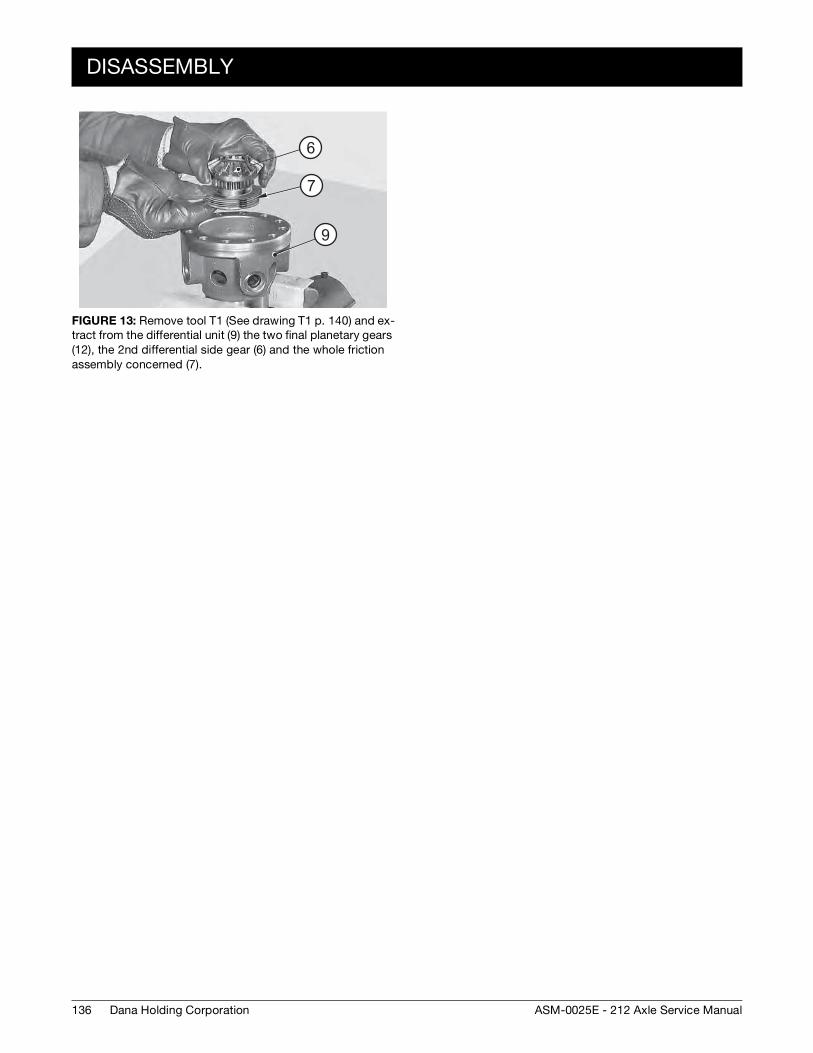
136
DISASSEMBLY
Dana Holding Corporation ASM-0025E - 212 Axle Service Manual
FIGURE 13: Remove tool T1 (See drawing T1 p. 140) and ex-tract from the differential unit (9) the two final planetary gears (12), the 2nd differential side gear (6) and the whole friction assembly concerned (7).
9
7
6
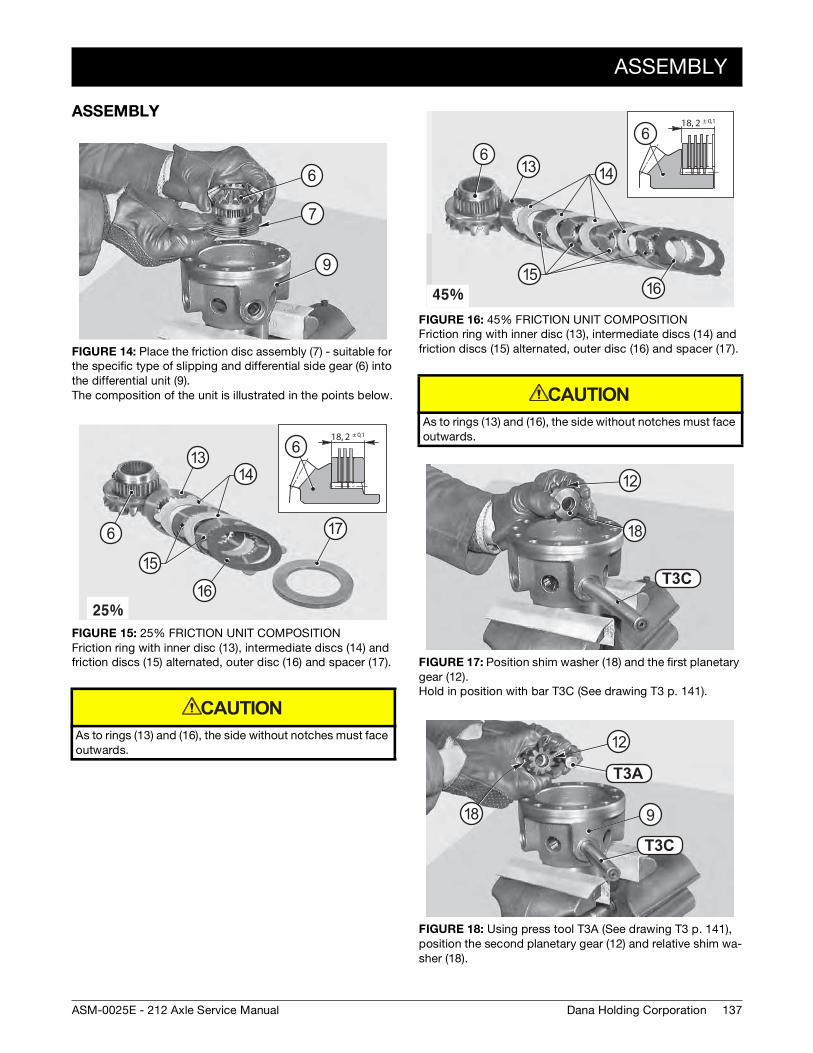
ASSEMBLY
137Dana Holding CorporationASM-0025E - 212 Axle Service Manual
ASSEMBLY
FIGURE 14: Place the friction disc assembly (7) - suitable for the specific type of slipping and differential side gear (6) into the differential unit (9). The composition of the unit is illustrated in the points below.
FIGURE 15: 25% FRICTION UNIT COMPOSITION Friction ring with inner disc (13), intermediate discs (14) and friction discs (15) alternated, outer disc (16) and spacer (17).
As to rings (13) and (16), the side without notches must face outwards.
9
7
6
18, 2 ± 0,1
6
6
16
17
15
1413
CAUTION
FIGURE 16: 45% FRICTION UNIT COMPOSITION Friction ring with inner disc (13), intermediate discs (14) and friction discs (15) alternated, outer disc (16) and spacer (17).
As to rings (13) and (16), the side without notches must face outwards.
FIGURE 17: Position shim washer (18) and the first planetary gear (12). Hold in position with bar T3C (See drawing T3 p. 141).
FIGURE 18: Using press tool T3A (See drawing T3 p. 141), position the second planetary gear (12) and relative shim wa-sher (18).
18, 2 ± 0,1
66
1516
1413
CAUTION
T16CT3C
12
18
T16A
T1 6C
T3A
T3C
9
12
18
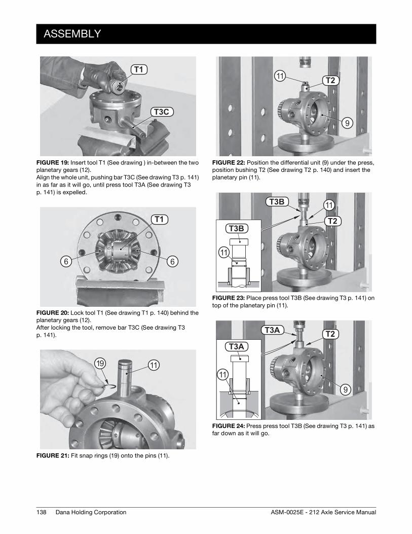
138
ASSEMBLY
Dana Holding Corporation ASM-0025E - 212 Axle Service Manual
FIGURE 19: Insert tool T1 (See drawing ) in-between the two planetary gears (12). Align the whole unit, pushing bar T3C (See drawing T3 p. 141) in as far as it will go, until press tool T3A (See drawing T3 p. 141) is expelled.
FIGURE 20: Lock tool T1 (See drawing T1 p. 140) behind the planetary gears (12). After locking the tool, remove bar T3C (See drawing T3 p. 141).
FIGURE 21: Fit snap rings (19) onto the pins (11).
T16C
T1 4T1
T3C
T1 4T1
66
1119
FIGURE 22: Position the differential unit (9) under the press, position bushing T2 (See drawing T2 p. 140) and insert the planetary pin (11).
FIGURE 23: Place press tool T3B (See drawing T3 p. 141) on top of the planetary pin (11).
FIGURE 24: Press press tool T3B (See drawing T3 p. 141) as far down as it will go.
T1 5T2
9
11
T1 5
T16B
T16BT2
T3B
T3B 11
11
T16AT1 5
T16AT3A
T3A T2
9
11
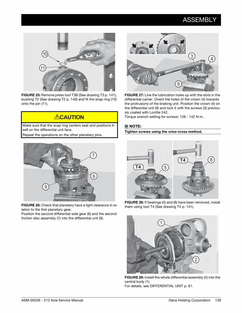
ASSEMBLY
139Dana Holding CorporationASM-0025E - 212 Axle Service Manual
FIGURE 25: Remove press tool T3B (See drawing T3 p. 141), bushing T2 (See drawing T2 p. 140) and fit the snap ring (10) onto the pin (11).
Make sure that the snap ring centers seat and positions it-self on the differential unit face.
Repeat the operations on the other planetary pins.
FIGURE 26: Check that planetary have a light clearance in re-lation to the first planetary gear. Position the second differential side gear (6) and the second friction disc assembly (7) into the differential unit (9).
10
11
CAUTION
6
7
9
FIGURE 27: Line the lubrication holes up with the slots in the differential carrier. Orient the holes of the crown (4) towards the protrusions of the braking unit. Position the crown (4) on the differential unit (9) and lock it with the screws (3) previou-sly coated with Loctite 242. Torque wrench setting for screws: 128 - 142 N·m.
NOTE:
Tighten screws using the criss-cross method.
FIGURE 28: If bearings (5) and (8) have been removed, install them using tool T4 (See drawing T4 p. 141).
FIGURE 29: Install the whole differential assembly (2) into the central body (1). For details, see DIFFERENTIAL UNIT p. 61.
3 4
9
T1 7
T1 7
T4T4
58
2
1
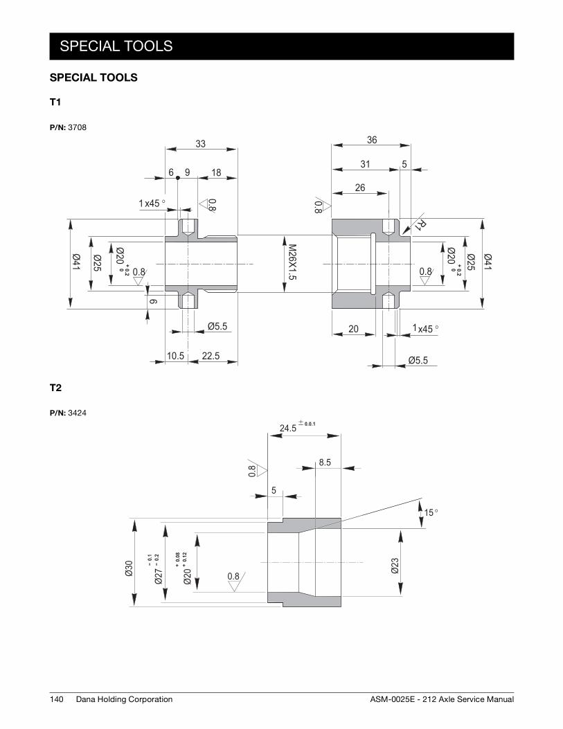
140
SPECIAL TOOLS
Dana Holding Corporation ASM-0025E - 212 Axle Service Manual
SPECIAL TOOLS
T1
T2
P/N: 3708
0.8
0.8
0.8
0.8
x45 °1
Ø41
Ø25
Ø20
+0.20
2618
36
5
20
Ø5.5
R1
M26X1.5
96
33
Ø25
Ø41
Ø20
+ 0.20
6
Ø5.5
22.510.5
x45 °1
31
P/N: 3424
0.8
0.8Ø30 --
0.1
-- 0
.2Ø
27
+ 0
.08
+ 0
.12
Ø20
5
8.5
24.5 0.0.1
Ø23
15 °
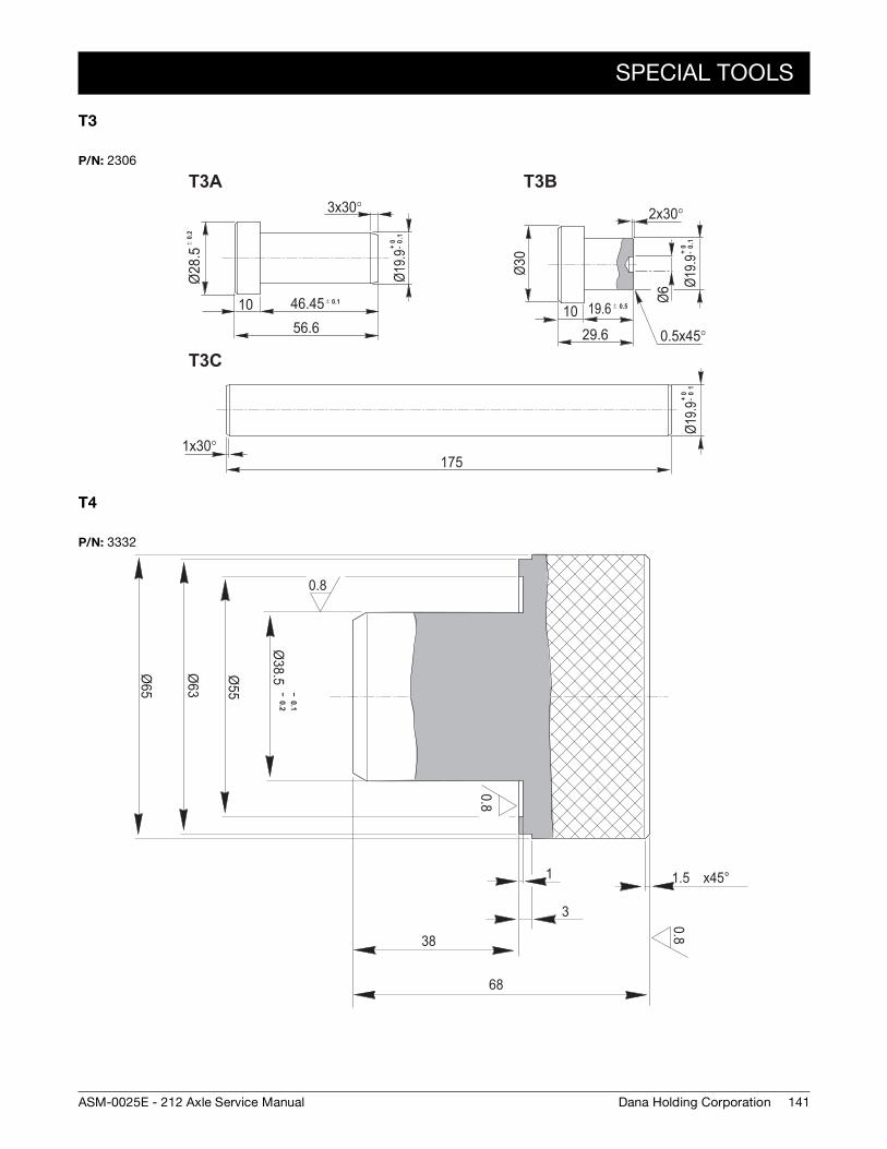
SPECIAL TOOLS
141Dana Holding CorporationASM-0025E - 212 Axle Service Manual
T3
T4
P/N: 2306
5.82Ø
46.451056.6
x30°3
9.91Ø Ø03
2x30°
1029.6
Ø6
19.6
x45°0.5
x30°1175
9.91Ø9.91Ø
T3A
T3C
T3B
+0 -
1.0 ± 0.
2
± 0.5± 0.1
+0 -
10
+0
-1.0
P/N: 3332
0.8
0.8
0.8
-- 0.1-- 0.2
Ø38.5Ø
55
Ø63
Ø65
38
68
3
1 x45°1.5

142
SPECIAL TOOLS
Dana Holding Corporation ASM-0025E - 212 Axle Service Manual
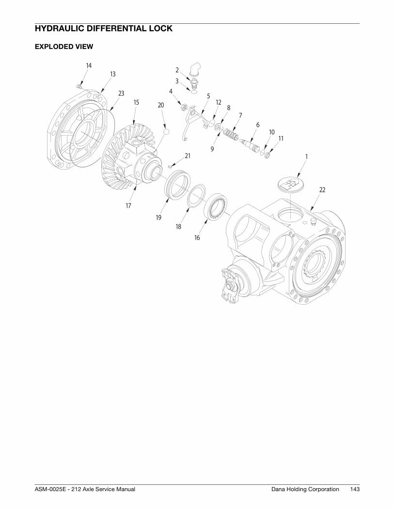
143Dana Holding CorporationASM-0025E - 212 Axle Service Manual
HYDRAULIC DIFFERENTIAL LOCK
EXPLODED VIEW
1
23
45
67
8
9
1011
12
1314
15
16
17
1819
20
21
22
23
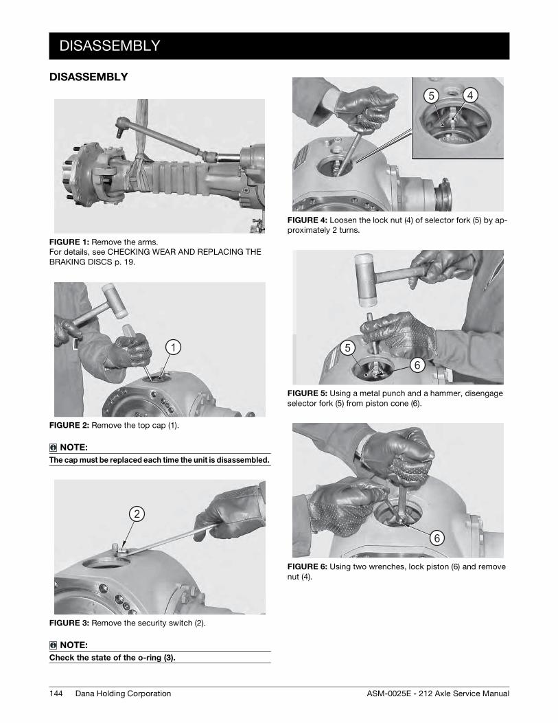
144
DISASSEMBLY
Dana Holding Corporation ASM-0025E - 212 Axle Service Manual
DISASSEMBLY
FIGURE 1: Remove the arms. For details, see CHECKING WEAR AND REPLACING THE BRAKING DISCS p. 19.
FIGURE 2: Remove the top cap (1).
NOTE:
The cap must be replaced each time the unit is disassembled.
FIGURE 3: Remove the security switch (2).
NOTE:
Check the state of the o-ring (3).
1
2
FIGURE 4: Loosen the lock nut (4) of selector fork (5) by ap-proximately 2 turns.
FIGURE 5: Using a metal punch and a hammer, disengage selector fork (5) from piston cone (6).
FIGURE 6: Using two wrenches, lock piston (6) and remove nut (4).
5 4
56
6
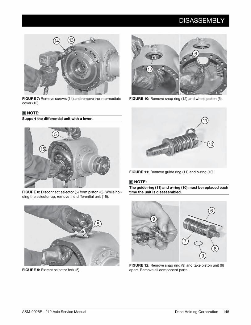
DISASSEMBLY
145Dana Holding CorporationASM-0025E - 212 Axle Service Manual
FIGURE 7: Remove screws (14) and remove the intermediate cover (13).
NOTE:
Support the differential unit with a lever.
FIGURE 8: Disconnect selector (5) from piston (6). While hol-ding the selector up, remove the differential unit (15).
FIGURE 9: Extract selector fork (5).
14 13
5
15
5
FIGURE 10: Remove snap ring (12) and whole piston (6).
FIGURE 11: Remove guide ring (11) and o-ring (10).
NOTE:
The guide ring (11) and o-ring (10) must be replaced each
time the unit is disassembled.
FIGURE 12: Remove snap ring (9) and take piston unit (6) apart. Remove all component parts.
6
12
10
11
9
9
6
78
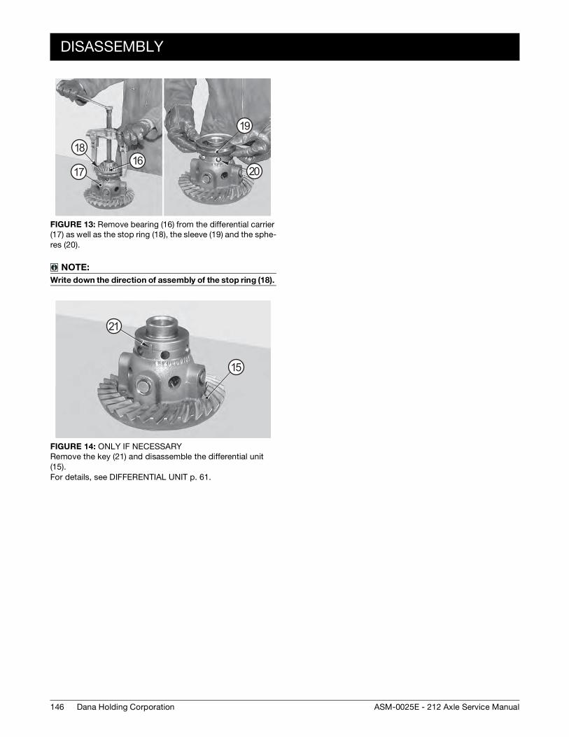
146
DISASSEMBLY
Dana Holding Corporation ASM-0025E - 212 Axle Service Manual
FIGURE 13: Remove bearing (16) from the differential carrier (17) as well as the stop ring (18), the sleeve (19) and the sphe-res (20).
NOTE:
Write down the direction of assembly of the stop ring (18).
FIGURE 14: ONLY IF NECESSARY Remove the key (21) and disassemble the differential unit (15). For details, see DIFFERENTIAL UNIT p. 61.
16
19
18
17 20
15
21
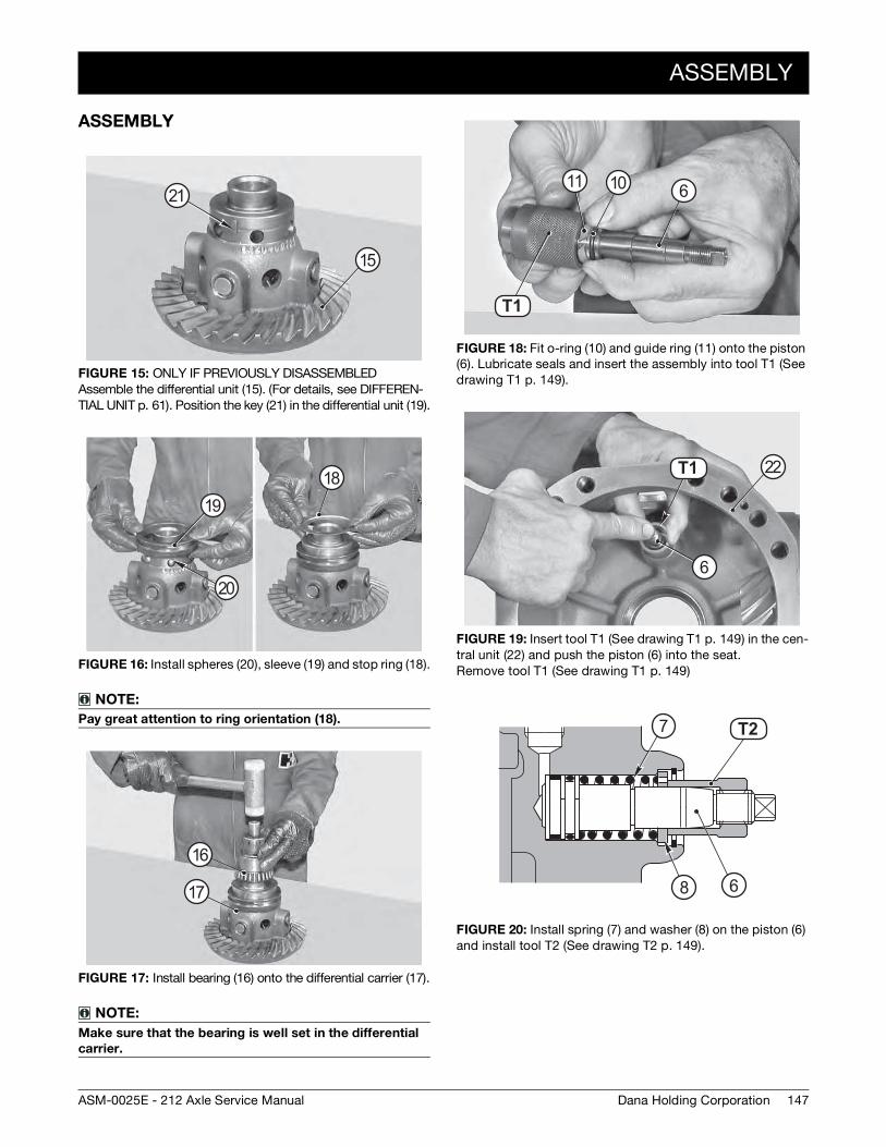
ASSEMBLY
147Dana Holding CorporationASM-0025E - 212 Axle Service Manual
ASSEMBLY
FIGURE 15: ONLY IF PREVIOUSLY DISASSEMBLED Assemble the differential unit (15). (For details, see DIFFEREN-TIAL UNIT p. 61). Position the key (21) in the differential unit (19).
FIGURE 16: Install spheres (20), sleeve (19) and stop ring (18).
NOTE:
Pay great attention to ring orientation (18).
FIGURE 17: Install bearing (16) onto the differential carrier (17).
NOTE:
Make sure that the bearing is well set in the differential
carrier.
15
21
20
1918
16
17
FIGURE 18: Fit o-ring (10) and guide ring (11) onto the piston (6). Lubricate seals and insert the assembly into tool T1 (See drawing T1 p. 149).
FIGURE 19: Insert tool T1 (See drawing T1 p. 149) in the cen-tral unit (22) and push the piston (6) into the seat. Remove tool T1 (See drawing T1 p. 149)
FIGURE 20: Install spring (7) and washer (8) on the piston (6) and install tool T2 (See drawing T2 p. 149).
T2 9T1
611 10
T2 9T1
6
22
T3 0T2
6
7
8
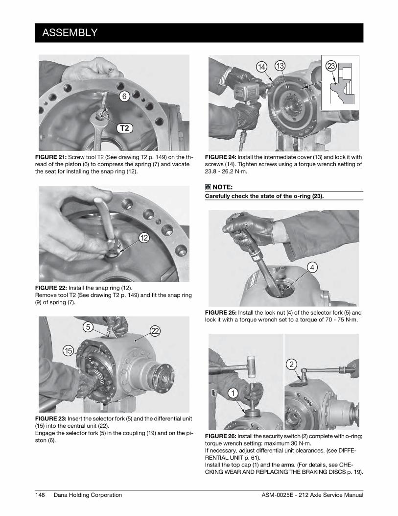
148
ASSEMBLY
Dana Holding Corporation ASM-0025E - 212 Axle Service Manual
FIGURE 21: Screw tool T2 (See drawing T2 p. 149) on the th-read of the piston (6) to compress the spring (7) and vacate the seat for installing the snap ring (12).
FIGURE 22: Install the snap ring (12). Remove tool T2 (See drawing T2 p. 149) and fit the snap ring (9) of spring (7).
FIGURE 23: Insert the selector fork (5) and the differential unit (15) into the central unit (22). Engage the selector fork (5) in the coupling (19) and on the pi-ston (6).
T3 0T2
6
12
5
15
22
FIGURE 24: Install the intermediate cover (13) and lock it with screws (14). Tighten screws using a torque wrench setting of 23.8 - 26.2 N·m.
NOTE:
Carefully check the state of the o-ring (23).
FIGURE 25: Install the lock nut (4) of the selector fork (5) and lock it with a torque wrench set to a torque of 70 - 75 N·m.
FIGURE 26: Install the security switch (2) complete with o-ring; torque wrench setting: maximum 30 N·m. If necessary, adjust differential unit clearances. (see DIFFE-RENTIAL UNIT p. 61). Install the top cap (1) and the arms. (For details, see CHE-CKING WEAR AND REPLACING THE BRAKING DISCS p. 19).
2314 13
4
2
1
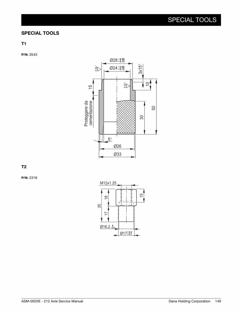
SPECIAL TOOLS
149Dana Holding CorporationASM-0025E - 212 Axle Service Manual
SPECIAL TOOLS
T1
T2
P/N: 3543
Ø33
Ø26
-- 0.08-- 0.12Ø28-- 0.08-- 0.12Ø24
1030
50
3x15
°5°
15Pr
oteg
gere
da
cem
enta
zione
0.8
0.8
P/N: 2316
18
M12x1.25
17
35
+ 0.2+ 0.1Ø17
Ø16.2 0-- 0.1
15

150
SPECIAL TOOLS
Dana Holding Corporation ASM-0025E - 212 Axle Service Manual
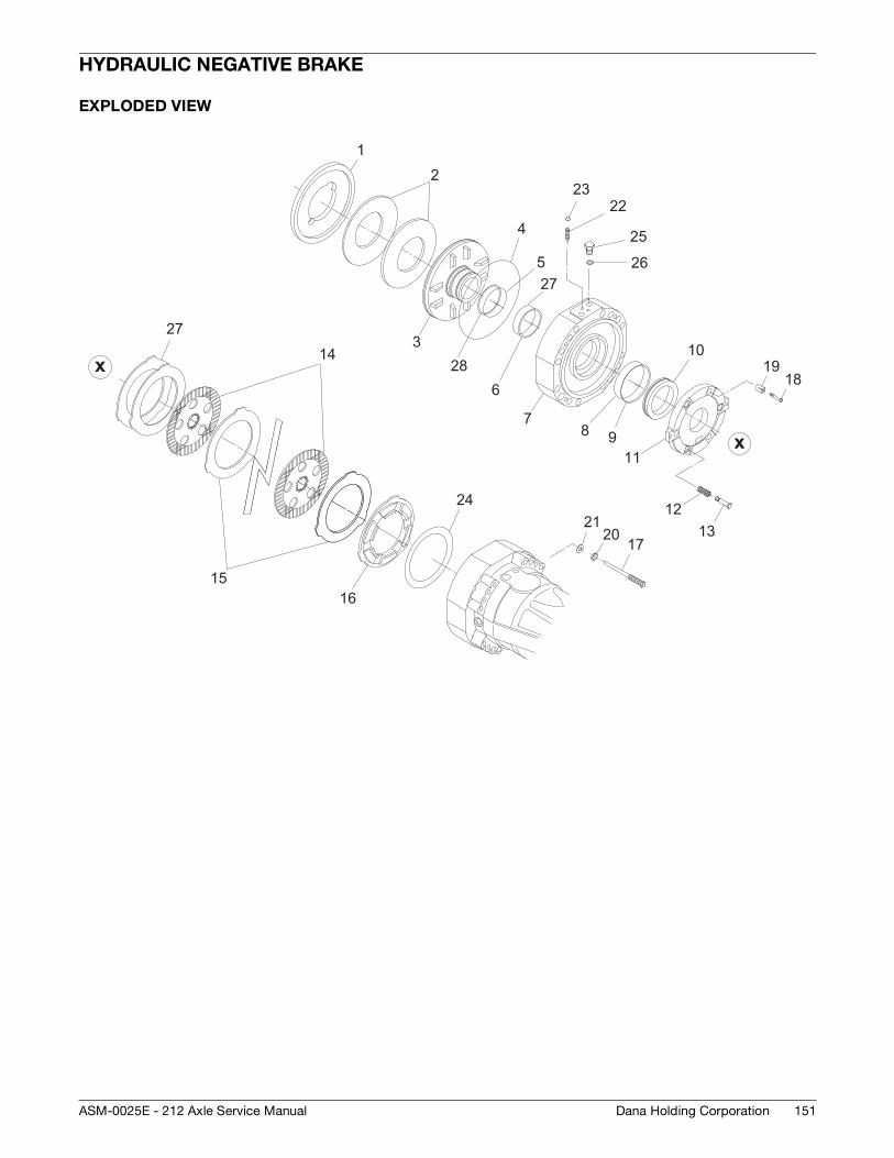
151Dana Holding CorporationASM-0025E - 212 Axle Service Manual
HYDRAULIC NEGATIVE BRAKE
EXPLODED VIEW
1
328
6
2
4
527
2322
25
26
78
11
1019
18
1213
9
14
1516
2120 17
24
27
x
x
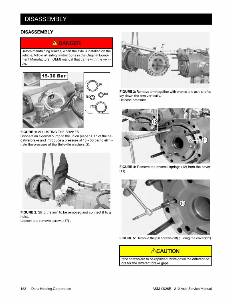
152
DISASSEMBLY
Dana Holding Corporation ASM-0025E - 212 Axle Service Manual
DISASSEMBLY
Before maintaining brakes, when the axle is installed on the vehicle, follow all safety instructions in the Original Equip-ment Manufacturer (OEM) manual that came with the vehi-cle.
FIGURE 1: ADJUSTING THE BRAKESConnect an external pump to the union piece “ P1 “ of the ne-gative brake and introduce a pressure of 15 - 30 bar to elimi-nate the pressure of the Belleville washers (2).
FIGURE 2: Sling the arm to be removed and connect it to a hoist.Loosen and remove screws (17) .
DANGER
FIGURE 3: Remove arm together with brakes and axle shafts; lay down the arm vertically.Release pressure.
FIGURE 4: Remove the reversal springs (12) from the cover (11).
FIGURE 5: Remove the pin screws (18) guiding the cover (11).
If the screws are to be replaced, write down the different co-lors for the different brake gaps.
1212
11
18
CAUTION
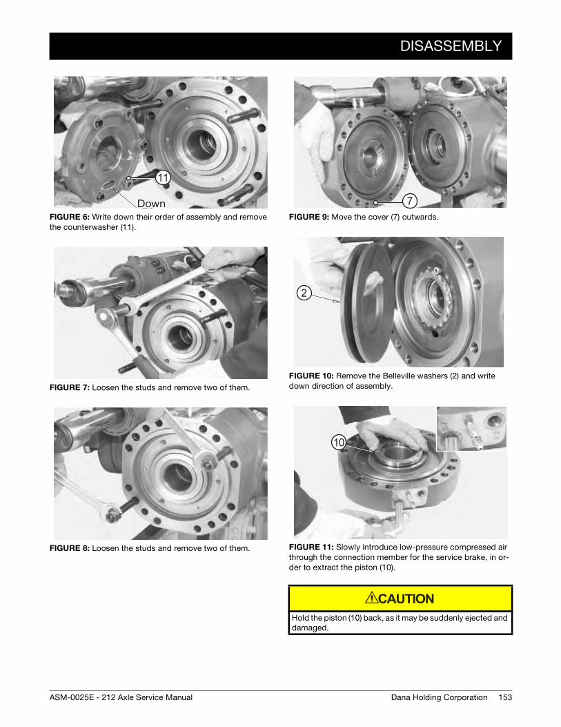
DISASSEMBLY
153Dana Holding CorporationASM-0025E - 212 Axle Service Manual
FIGURE 6: Write down their order of assembly and remove the counterwasher (11).
FIGURE 7: Loosen the studs and remove two of them.
FIGURE 8: Loosen the studs and remove two of them.
11
FIGURE 9: Move the cover (7) outwards.
FIGURE 10: Remove the Belleville washers (2) and write down direction of assembly.
FIGURE 11: Slowly introduce low-pressure compressed air through the connection member for the service brake, in or-der to extract the piston (10).
Hold the piston (10) back, as it may be suddenly ejected and damaged.
7
2
10
CAUTION
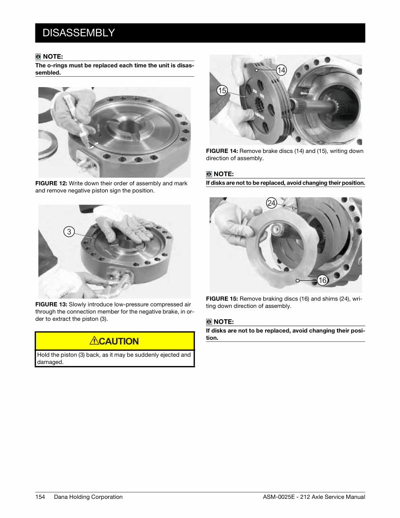
154
DISASSEMBLY
Dana Holding Corporation ASM-0025E - 212 Axle Service Manual
NOTE:
The o-rings must be replaced each time the unit is disas-
sembled.
FIGURE 12: Write down their order of assembly and mark and remove negative piston sign the position.
FIGURE 13: Slowly introduce low-pressure compressed air through the connection member for the negative brake, in or-der to extract the piston (3).
Hold the piston (3) back, as it may be suddenly ejected and damaged.
3
CAUTION
FIGURE 14: Remove brake discs (14) and (15), writing down direction of assembly.
NOTE:
If disks are not to be replaced, avoid changing their position.
FIGURE 15: Remove braking discs (16) and shims (24), wri-ting down direction of assembly.
NOTE:
If disks are not to be replaced, avoid changing their posi-
tion.
14
15
24
16
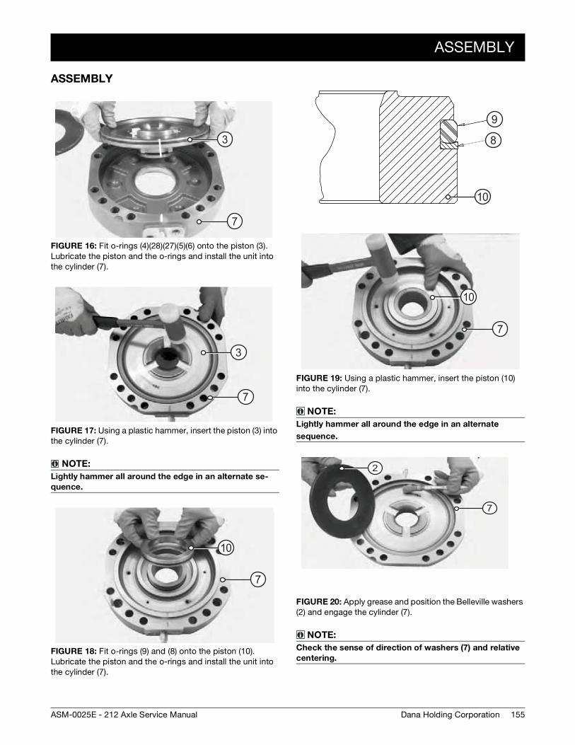
ASSEMBLY
155Dana Holding CorporationASM-0025E - 212 Axle Service Manual
ASSEMBLY
FIGURE 16: Fit o-rings (4)(28)(27)(5)(6) onto the piston (3).Lubricate the piston and the o-rings and install the unit into the cylinder (7).
FIGURE 17: Using a plastic hammer, insert the piston (3) into the cylinder (7).
NOTE:
Lightly hammer all around the edge in an alternate se-
quence.
FIGURE 18: Fit o-rings (9) and (8) onto the piston (10).Lubricate the piston and the o-rings and install the unit into the cylinder (7).
3
7
3
7
10
7
FIGURE 19: Using a plastic hammer, insert the piston (10) into the cylinder (7).
NOTE:
Lightly hammer all around the edge in an alternate
sequence.
FIGURE 20: Apply grease and position the Belleville washers (2) and engage the cylinder (7).
NOTE:
Check the sense of direction of washers (7) and relative
centering.
10
9
8
10
7
2
7
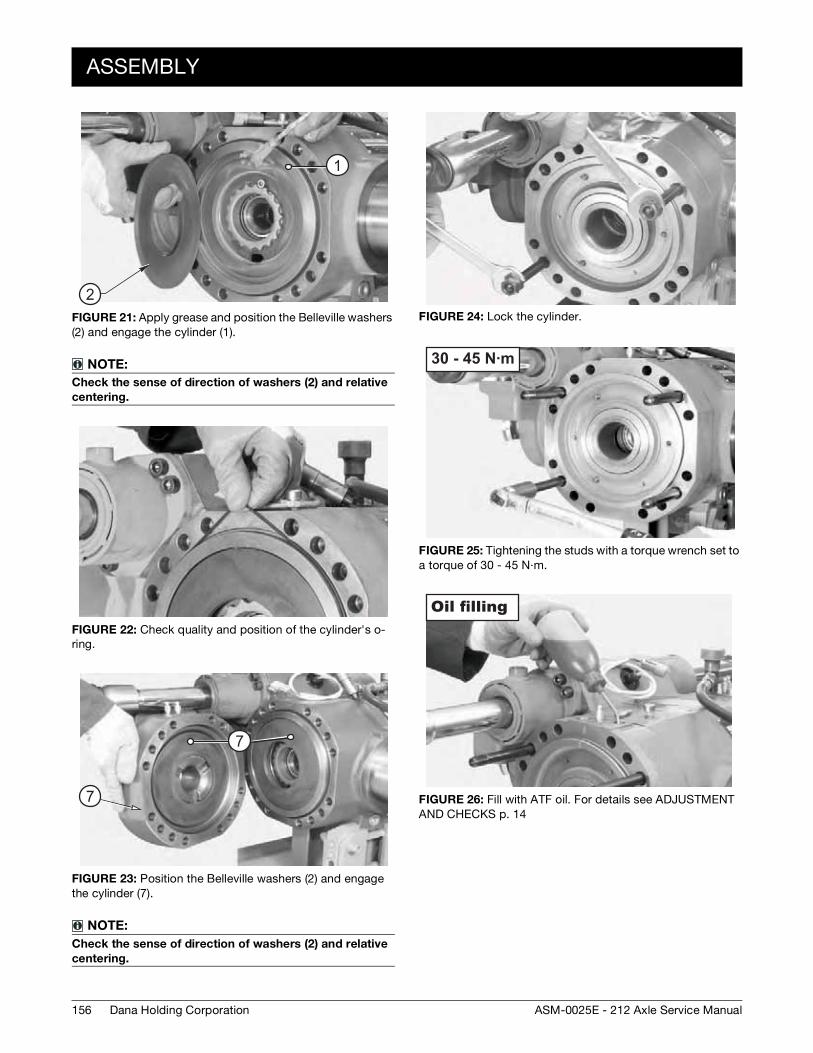
156
ASSEMBLY
Dana Holding Corporation ASM-0025E - 212 Axle Service Manual
FIGURE 21: Apply grease and position the Belleville washers (2) and engage the cylinder (1).
NOTE:
Check the sense of direction of washers (2) and relative
centering.
FIGURE 22: Check quality and position of the cylinder's o-ring.
FIGURE 23: Position the Belleville washers (2) and engage the cylinder (7).
NOTE:
Check the sense of direction of washers (2) and relative
centering.
2
1
7
7
FIGURE 24: Lock the cylinder.
FIGURE 25: Tightening the studs with a torque wrench set to a torque of 30 - 45 N·m.
FIGURE 26: Fill with ATF oil. For details see ADJUSTMENT AND CHECKS p. 14
30 - 45 N·m
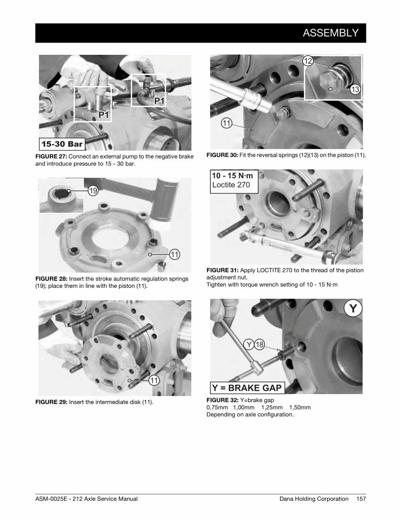
ASSEMBLY
157Dana Holding CorporationASM-0025E - 212 Axle Service Manual
FIGURE 27: Connect an external pump to the negative brake and introduce pressure to 15 - 30 bar.
FIGURE 28: Insert the stroke automatic regulation springs (19); place them in line with the piston (11).
FIGURE 29: Insert the intermediate disk (11).
11
19
11
FIGURE 30: Fit the reversal springs (12)(13) on the piston (11).
FIGURE 31: Apply LOCTITE 270 to the thread of the pistion adjustment nut. Tighten with torque wrench setting of 10 - 15 N·m
FIGURE 32: Y=brake gap0,75mm 1,00mm 1,25mm 1,50mm Depending on axle configuration.
11
12
13
10 - 15 N·m
Y 18
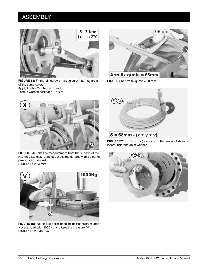
158
ASSEMBLY
Dana Holding Corporation ASM-0025E - 212 Axle Service Manual
FIGURE 33: Fit the pin screws making sure that they are all of the same color.Apply Loctite 270 to the thread.Torque wrench setting: 5 - 7 N·m.
FIGURE 34: Take the measurement from the surface of the intermediate disk to the cover sealing surface with 30 bar of pressure introduced.EXAMPLE: 25.4 mm
FIGURE 35: Put the brake disc pack including the shim under a press, load with 1000 kg and take the measure “V”.EXAMPLE: V = 40 mm
5 - 7 N·m
FIGURE 36: Arm fix quote = 68 mm
FIGURE 37: S = 68 mm - ( x + y + v ) = Thickness of shims to insert under the shim washer.
24S
S 24
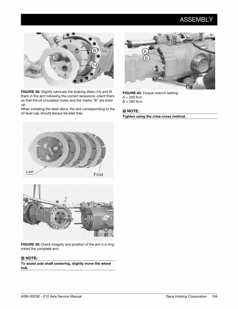
ASSEMBLY
159Dana Holding CorporationASM-0025E - 212 Axle Service Manual
FIGURE 38: Slightly lubricate the braking disks (14) and fit them in the arm following the correct sequence; orient them so that the oil circulation holes and the marks “B” are lined up.When installing the steel discs, the slot corresponding to the oil level cap should always be kept free.
FIGURE 39: Check integrity and position of the arm's o-ring; install the complete arm.
NOTE:
To assist axle shaft centering, slightly move the wheel
hub.
B
14
FIGURE 40: Torque wrench setting:A = 200 N·m B = 283 N·m
NOTE:
Tighten using the criss-cross method.
AB

160
ASSEMBLY
Dana Holding Corporation ASM-0025E - 212 Axle Service Manual
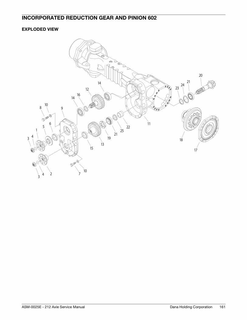
161Dana Holding CorporationASM-0025E - 212 Axle Service Manual
INCORPORATED REDUCTION GEAR AND PINION 602
EXPLODED VIEW
1
23 4 7
8 9
10
12
13
14
15
16
1921
2225
3 4
56
10
14
11
17
18
20
2324
21
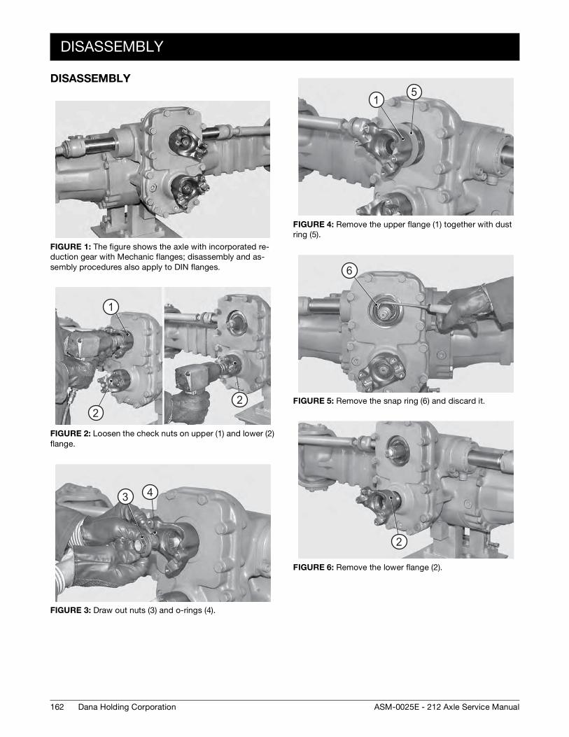
162
DISASSEMBLY
Dana Holding Corporation ASM-0025E - 212 Axle Service Manual
DISASSEMBLY
FIGURE 1: The figure shows the axle with incorporated re-duction gear with Mechanic flanges; disassembly and as-sembly procedures also apply to DIN flanges.
FIGURE 2: Loosen the check nuts on upper (1) and lower (2) flange.
FIGURE 3: Draw out nuts (3) and o-rings (4).
1
2 2
3 4
FIGURE 4: Remove the upper flange (1) together with dust ring (5).
FIGURE 5: Remove the snap ring (6) and discard it.
FIGURE 6: Remove the lower flange (2).
1 5
6
2
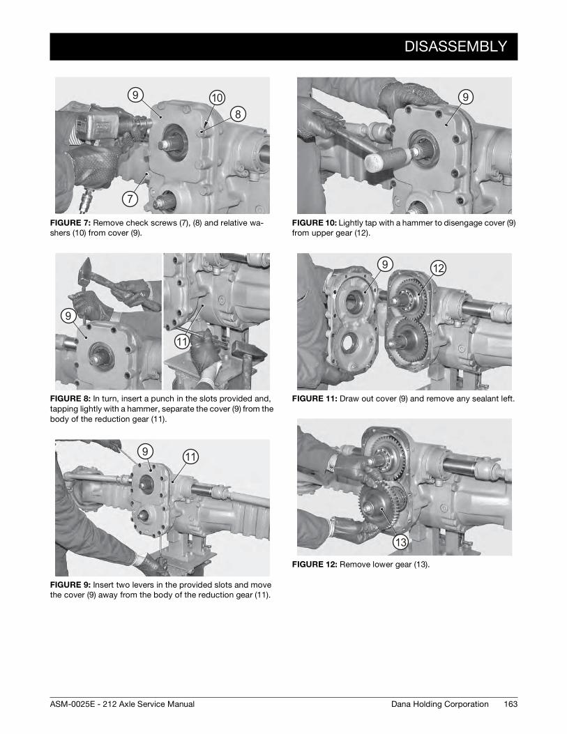
DISASSEMBLY
163Dana Holding CorporationASM-0025E - 212 Axle Service Manual
FIGURE 7: Remove check screws (7), (8) and relative wa-shers (10) from cover (9).
FIGURE 8: In turn, insert a punch in the slots provided and, tapping lightly with a hammer, separate the cover (9) from the body of the reduction gear (11).
FIGURE 9: Insert two levers in the provided slots and move the cover (9) away from the body of the reduction gear (11).
7
8
9 10
9
11
9 11
FIGURE 10: Lightly tap with a hammer to disengage cover (9) from upper gear (12).
FIGURE 11: Draw out cover (9) and remove any sealant left.
FIGURE 12: Remove lower gear (13).
9
9 12
13
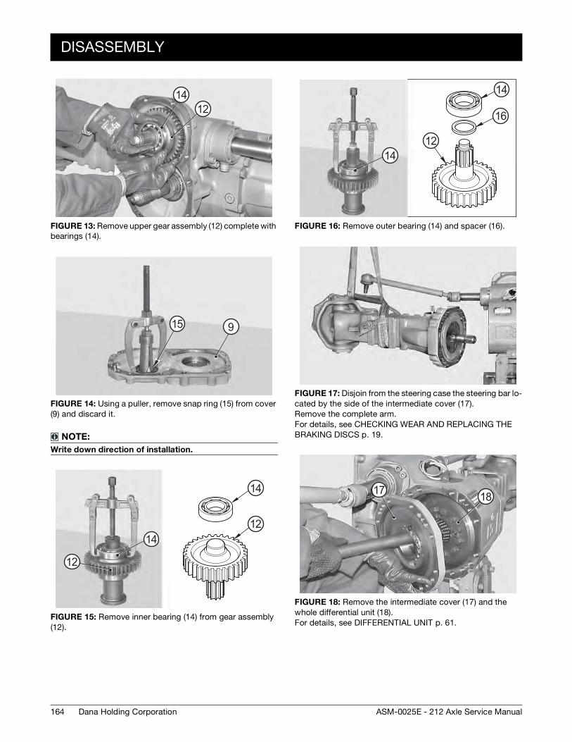
164
DISASSEMBLY
Dana Holding Corporation ASM-0025E - 212 Axle Service Manual
FIGURE 13: Remove upper gear assembly (12) complete with bearings (14).
FIGURE 14: Using a puller, remove snap ring (15) from cover (9) and discard it.
NOTE:
Write down direction of installation.
FIGURE 15: Remove inner bearing (14) from gear assembly (12).
1214
15 9
12
1214
14
FIGURE 16: Remove outer bearing (14) and spacer (16).
FIGURE 17: Disjoin from the steering case the steering bar lo-cated by the side of the intermediate cover (17). Remove the complete arm. For details, see CHECKING WEAR AND REPLACING THE BRAKING DISCS p. 19.
FIGURE 18: Remove the intermediate cover (17) and the whole differential unit (18). For details, see DIFFERENTIAL UNIT p. 61.
12
14
14
16
17 18
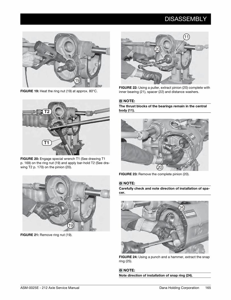
DISASSEMBLY
165Dana Holding CorporationASM-0025E - 212 Axle Service Manual
FIGURE 19: Heat the ring nut (19) at approx. 80°C.
FIGURE 20: Engage special wrench T1 (See drawing T1 p. 169) on the ring nut (19) and apply bar-hold T2 (See dra-wing T2 p. 170) on the pinion (20).
FIGURE 21: Remove ring nut (19).
19
T2 9
T3 0T1
T2
19
FIGURE 22: Using a puller, extract pinion (20) complete with inner bearing (21), spacer (22) and distance washers.
NOTE:
The thrust blocks of the bearings remain in the central
body (11).
FIGURE 23: Remove the complete pinion (20).
NOTE:
Carefully check and note direction of installation of spa-
cer.
FIGURE 24: Using a punch and a hammer, extract the snap ring (25).
NOTE:
Note direction of installation of snap ring (24).
20
11
20
25
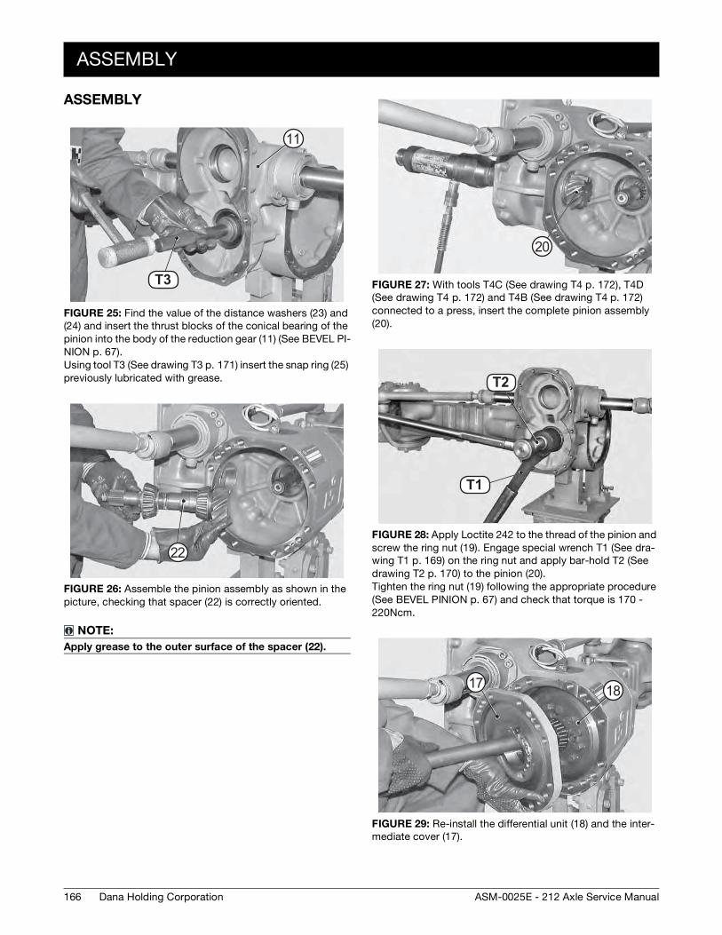
166
ASSEMBLY
Dana Holding Corporation ASM-0025E - 212 Axle Service Manual
ASSEMBLY
FIGURE 25: Find the value of the distance washers (23) and (24) and insert the thrust blocks of the conical bearing of the pinion into the body of the reduction gear (11) (See BEVEL PI-NION p. 67). Using tool T3 (See drawing T3 p. 171) insert the snap ring (25) previously lubricated with grease.
FIGURE 26: Assemble the pinion assembly as shown in the picture, checking that spacer (22) is correctly oriented.
NOTE:
Apply grease to the outer surface of the spacer (22).
T7T3
11
22
FIGURE 27: With tools T4C (See drawing T4 p. 172), T4D (See drawing T4 p. 172) and T4B (See drawing T4 p. 172) connected to a press, insert the complete pinion assembly (20).
FIGURE 28: Apply Loctite 242 to the thread of the pinion and screw the ring nut (19). Engage special wrench T1 (See dra-wing T1 p. 169) on the ring nut and apply bar-hold T2 (See drawing T2 p. 170) to the pinion (20). Tighten the ring nut (19) following the appropriate procedure (See BEVEL PINION p. 67) and check that torque is 170 - 220Ncm.
FIGURE 29: Re-install the differential unit (18) and the inter-mediate cover (17).
20
T2 9
T3 0T1
T2
17 18
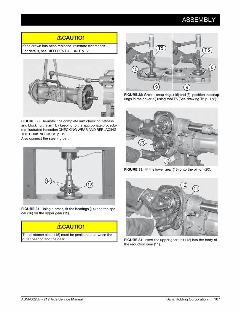
ASSEMBLY
167Dana Holding CorporationASM-0025E - 212 Axle Service Manual
If the crown has been replaced, reinstate clearances.
For details, see DIFFERENTIAL UNIT p. 61.
FIGURE 30: Re-install the complete arm checking flatness and blocking the arm by keeping to the appropriate procedu-res illustrated in section CHECKING WEAR AND REPLACING THE BRAKING DISCS p. 19. Also connect the steering bar.
FIGURE 31: Using a press, fit the bearings (14) and the spa-cer (16) on the upper gear (12).
The di stance piece (16) must be positioned between the outer bearing and the gear.
CAUTION
1412
CAUTION
FIGURE 32: Grease snap rings (15) and (6); position the snap rings in the cover (9) using tool T5 (See drawing T5 p. 173).
FIGURE 33: Fit the lower gear (13) onto the pinion (20).
FIGURE 34: Insert the upper gear unit (12) into the body of the reduction gear (11).
T3 2 T3 2T5 T5
15
9 9
6
20
13
1112
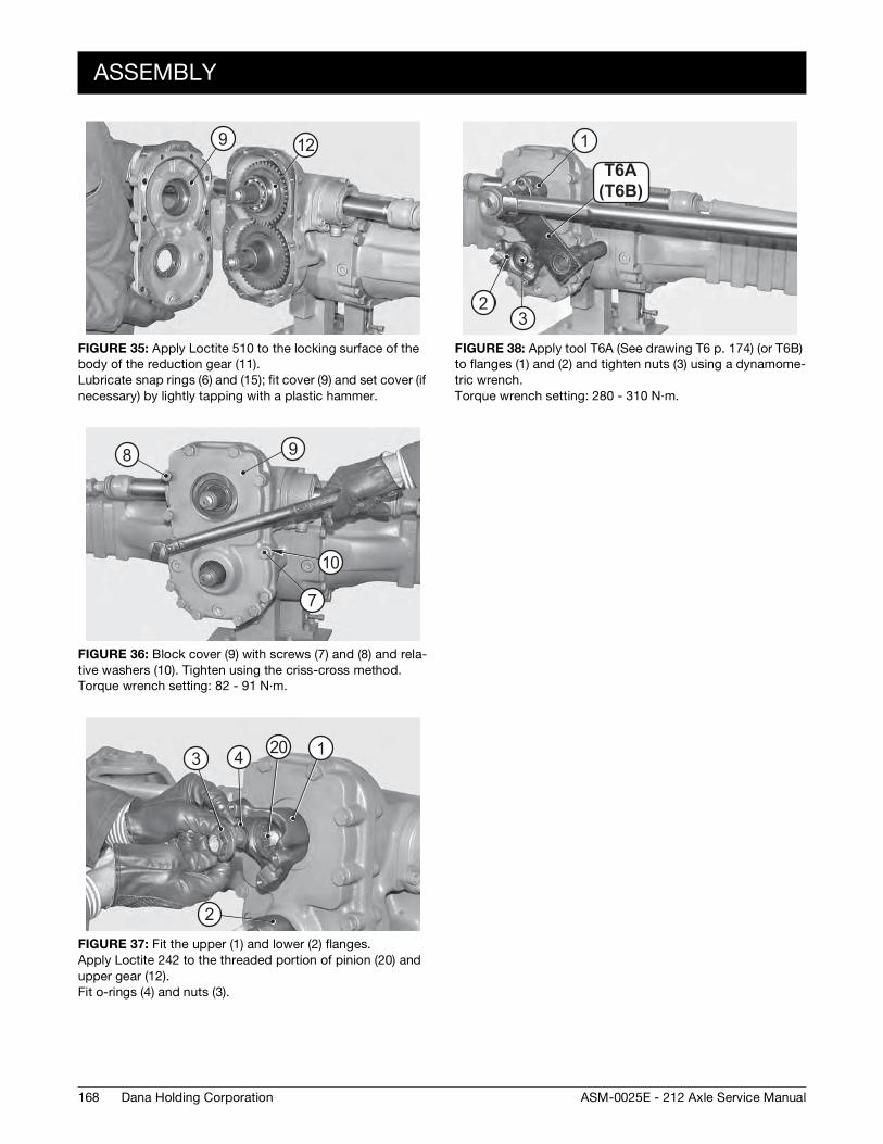
168
ASSEMBLY
Dana Holding Corporation ASM-0025E - 212 Axle Service Manual
FIGURE 35: Apply Loctite 510 to the locking surface of the body of the reduction gear (11). Lubricate snap rings (6) and (15); fit cover (9) and set cover (if necessary) by lightly tapping with a plastic hammer.
FIGURE 36: Block cover (9) with screws (7) and (8) and rela-tive washers (10). Tighten using the criss-cross method. Torque wrench setting: 82 - 91 N·m.
FIGURE 37: Fit the upper (1) and lower (2) flanges. Apply Loctite 242 to the threaded portion of pinion (20) and upper gear (12). Fit o-rings (4) and nuts (3).
9 12
10
8 9
7
20 1
2
3 4
FIGURE 38: Apply tool T6A (See drawing T6 p. 174) (or T6B) to flanges (1) and (2) and tighten nuts (3) using a dynamome-tric wrench. Torque wrench setting: 280 - 310 N·m.
(T20B )T20AT6A(T6B)
1
23
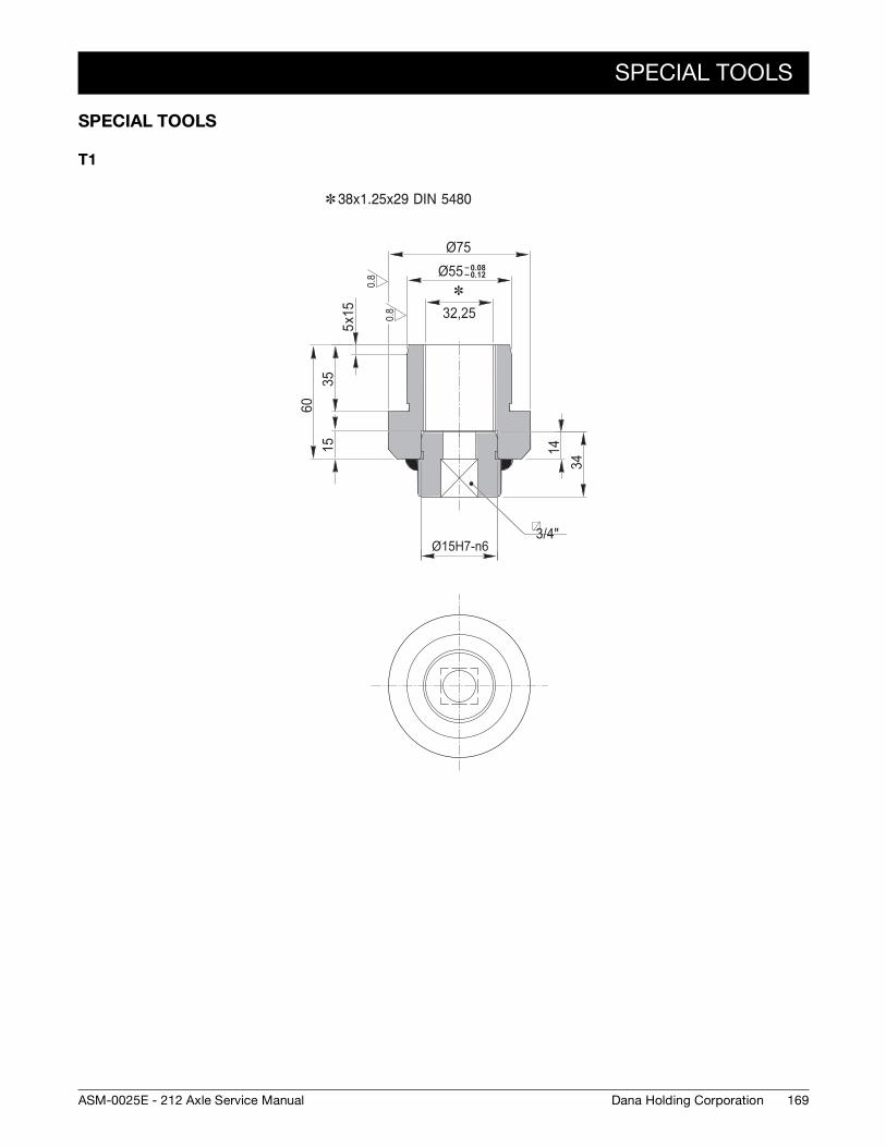
SPECIAL TOOLS
169Dana Holding CorporationASM-0025E - 212 Axle Service Manual
SPECIAL TOOLS
T1
0.8
0.8
3/4"Ø15H7-n6
– 0.08– 0.12Ø55
Ø75
35x1
55
6015 14
34
32,25
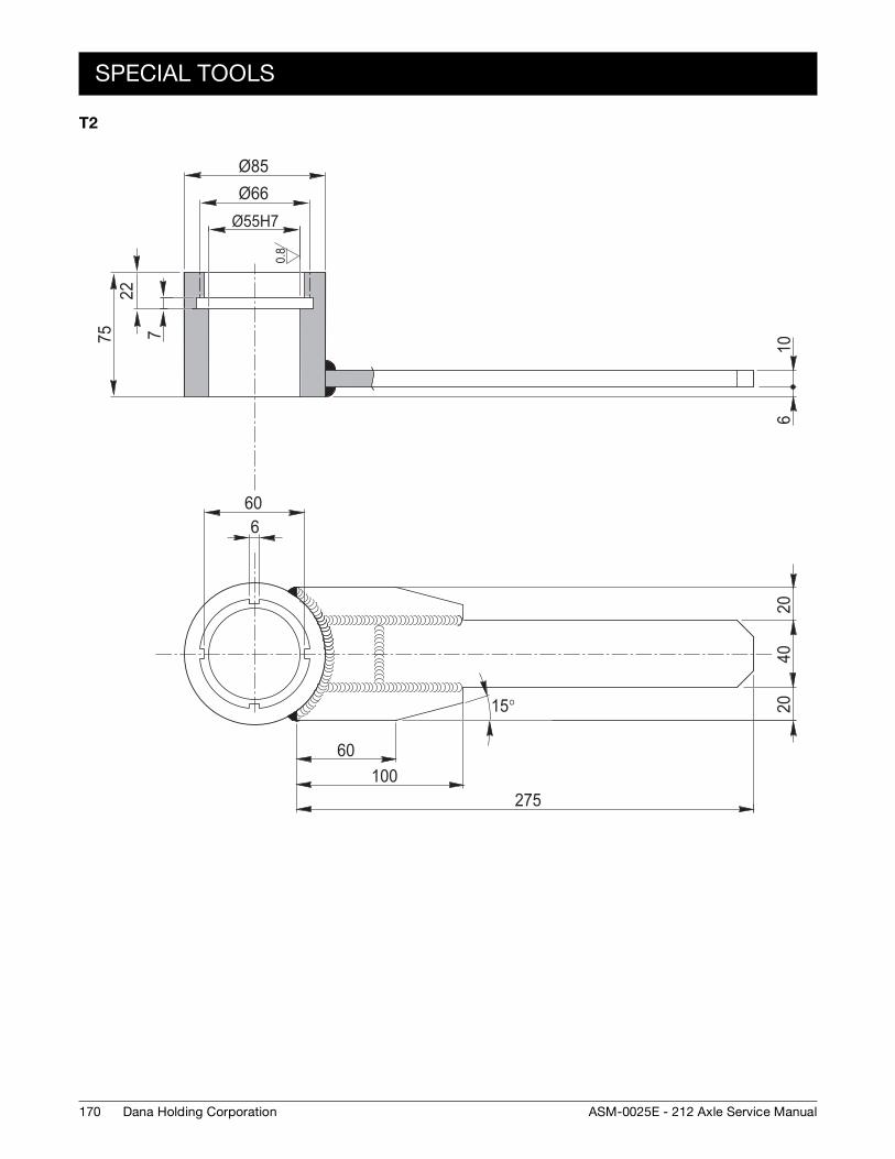
170
SPECIAL TOOLS
Dana Holding Corporation ASM-0025E - 212 Axle Service Manual
T2
0.8
Ø85
Ø55H7
7
60
Ø66
2275 10
620
4020
6
60100
275
15°
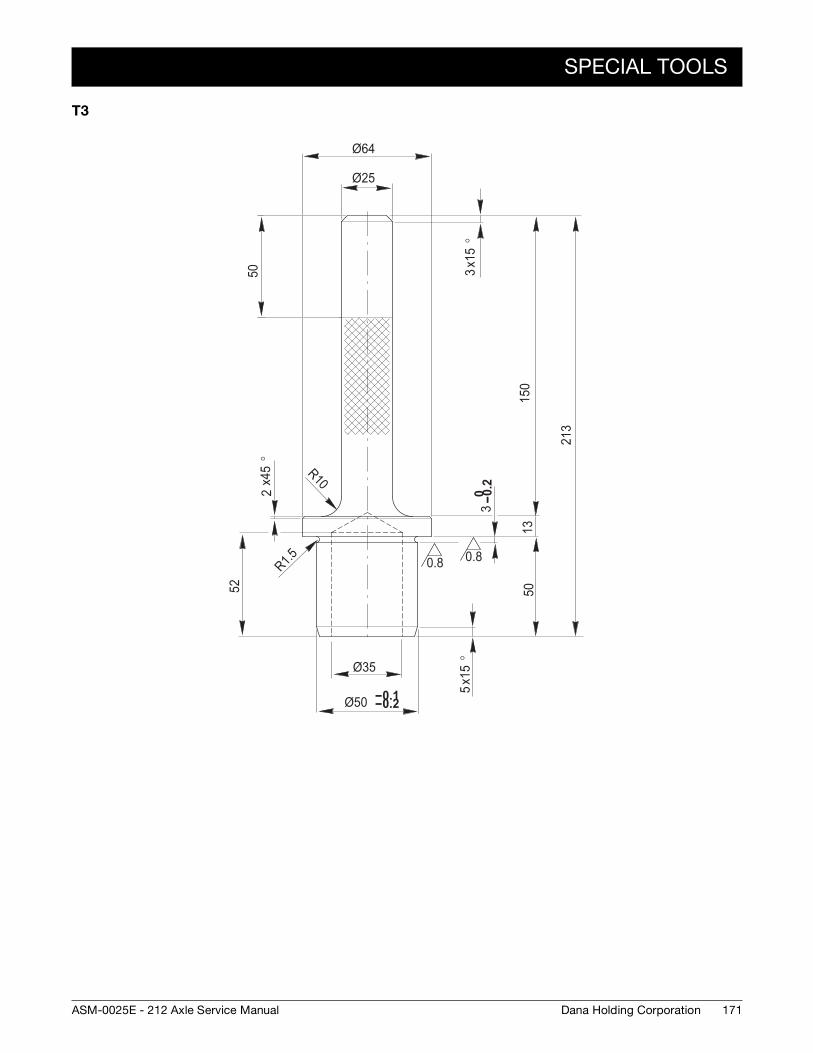
SPECIAL TOOLS
171Dana Holding CorporationASM-0025E - 212 Axle Service Manual
T3
0.8 0.8
Ø35
-- 0.1-- 0.2Ø50
Ø25
Ø64
50
x15
°3
0 -- 0.2
3
1350
150
213
52
x15
°5
R1.5
R10x45
°2
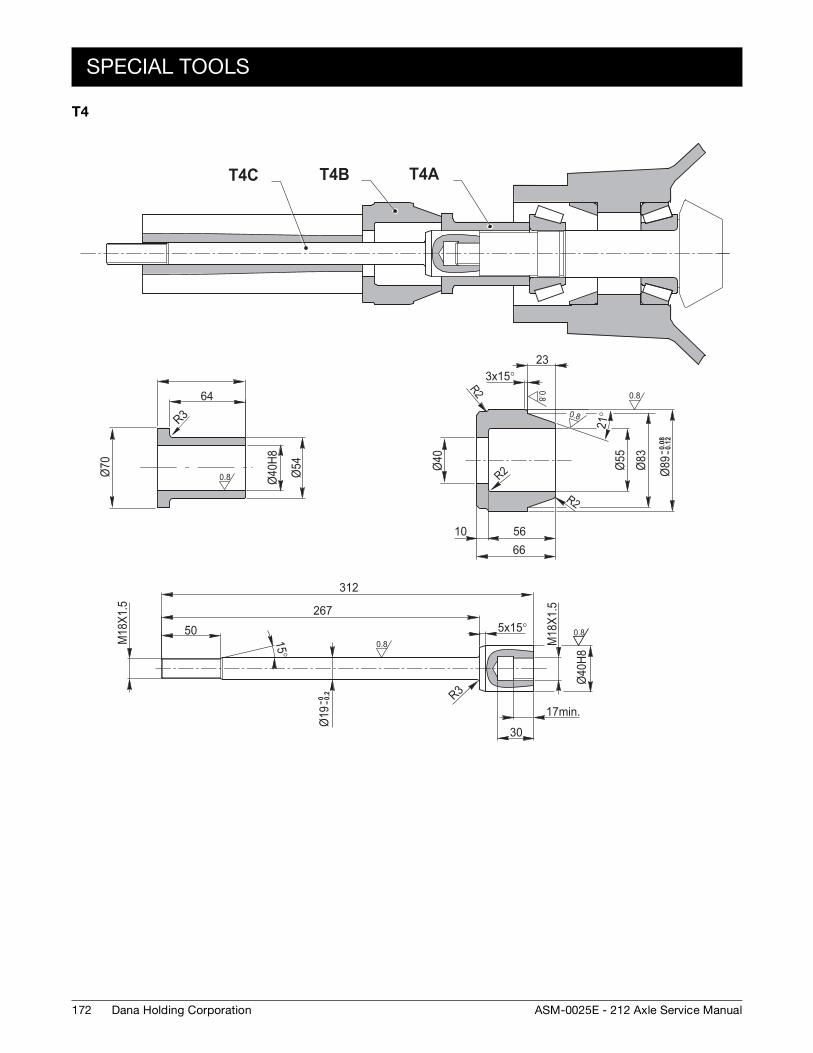
172
SPECIAL TOOLS
Dana Holding Corporation ASM-0025E - 212 Axle Service Manual
T4
T4C T4B T4A
64
Ø40
H8
Ø54Ø70
M18
X1.5
50267
312
5x15°
M18
X1.5
Ø40
H8
30
17min.R3
R3
233x15°
Ø40 Ø55
Ø83 -- 0
.08
-- 0.1
2Ø
89
561066
21°
R2
R2
R2
15°
-- 0 -- 0.2
Ø19
0.8
0.8
0.8
0.80.8
0.8
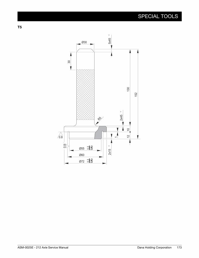
SPECIAL TOOLS
173Dana Holding CorporationASM-0025E - 212 Axle Service Manual
T5
0.8
0.8
2x15
°
2x45
°
5x45
°
R5
Ø55
Ø60
-- 0.2-- 0.3
Ø72 -- 0.2-- 0.3
Ø30
30
130
1
1012
152
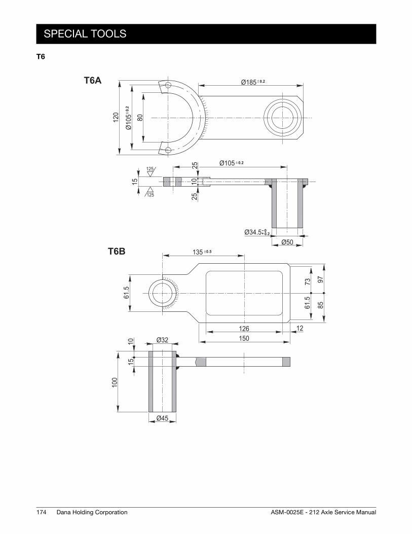
174
SPECIAL TOOLS
Dana Holding Corporation ASM-0025E - 212 Axle Service Manual
T6
80
± 0.
2Ø
105
120
15
± 0.2Ø105
2525
10
Ø50
± 0.2Ø185
-- 0+ 0.2Ø34.5
125
125
61.5
100
1510
Ø45
126150
12
61.5
73 9785
135 ±0.5
Ø32
T6A
T6B


For product inquiries or support,
visit www.dana.com or call 419-887-6445
For other service publications,
visit www.SpicerParts.com/literature.asp
For online service parts ordering,
visit www.SpicerParts.com/order.asp
Copyright 2013 Dana Holding Corporation
All content is subject to copyright by Dana and may not
be reproduced in whole or in part by any means,
electronic or otherwise, without prior written approval.
THIS INFORMATION IS NOT INTENDED FOR SALE OR
RESALE, AND THIS NOTICE MUST REMAIN ON ALL
COPIES.