service manual - the kalash connection · service manual 7.62-mm degtyarev light machine gun (rpd)...
TRANSCRIPT

SERVICE MANUAL7.62-mm Degtyarev
Light Machine Gun (RPD)


7.62-MM DEGTYAREVLIGHT MACHINE GUN (RPD)
Service Manual


Table of Contents
Cunbst Characteristicsof the I~ . 1
Tictical—tecbnice.1d~t~ . . . .. ... . . . ... . . 1
II. ~onatzuctionott1~I~~ . .. 5
1. Brre]. .. . . .. . . ....•.....e..s.......... 5- 2. casing -. .......e......•.......•..•.•.............. 13
3. Bolt ~chanism . ..... ....... 16k. Trigger frame with butt and grip . ... .. . .. . . ..... 20
- 5. Trigger mechanism 226.- Belt feed with cover a ........... 237. Sighting i~chaniam 2~48. Rand guard • s........... ...... 299. Bipod. .es....•..•.•.s•..... 29
10. ~sumvithbelt .., ................. 3111. Spare parts and accessories ••.•••••••• 31
III. Disassemblingand Assemblingof the U~ 36
12. Partial Disassemblingand Assembling . . ................ 3613. Co~p1eteDisassemblingand. Assembling..................
1k. Disassembling and Assemblingin the OrdnanceM~~Mn~~$hOp 50
IV. Interaction of the Parts Diring Firing .................... 58
V. Technical Inspectionof the IZV~ . ... . . . . . ..... ... .... . 62
15. Daily Inspection of the Iz( ................ 6216. Inspection of the L~tin the AssembledState ........... 6317. Inspection of the It~ in the DisassembledState .. 65
VI. Preparationof the ZI’EI for Firing . . 71
18. Filling the Belt with Cartridgesand. Inserting it in theDrum 71
19. Ad.just~nt of the Regulator 76
VII. HSWiIi?tg of the U’~ in the Firing Position
20. Emplacementof the Iè~ 7821. kLjua~nt of the Sighting Mechanism . 7822. Loading of the IZ~ . ..... 79
i

23. Si*tthg with the I~ and Firing . .. . . . . . . . . . . . ........ 832k. Uflloading of the Ia~ .................................. 8425. )lswirei to Preventand 1i~1w.teStoppages ........... 84
VIII. Emaninstionof the Accuracy of Fire and the Testing of the••.*s.e..e...........................s................ 88
26. The Il~Must Be Tested. . .... .. .... .. .. 8827. Testing of the D~Daring Single-shotFire ............ 9128. Testing of the UW Daring *itc~aticFire .............. 97
IX. C1.’~’~g and Iaabication of the till . . . . . . . . . ..... .... ...... 99
29. The till Must Be-Cleaned and babricated ........ 9930. Materials To B. Used for CleRMng and Oiling . 9931. SequenceDaring Cleaniug;andOiling ................... 100
I. Stors~of the till . . . . . . . .. . . .. . . .. a ste. . 104
~. “ttion •... .. . . . . . ...•ess.s......s..•.s 106
32. General 55 S *• 5*5••e..5• ••5S •S5••• •S• 10633. t.tve Cartridges . ss..e•e...ssa..e 10634. Identification Characteristicsof the ~i11.~$ ......... 11035. i4odeofOpersticnofthaSpecia1~illeta .............. 110~6. Practice Cartridges . . . •0•e• . . .. . . ..•. 1].].37. ~a~ingof the Cartridges . as...... ....... 11-].38. SafekeepIngand Storing of the ~~niti~i ............. 111
ii

I. CO(B~CRAR~!~I~I~OF 1~till
The tell is the most importantantonatic t~eaponof the till team. It isused. for the destructionof exposedliving group targets andof importantindividusl targetsup to a distanceof 800 a and for ecabatagainstair
targetsto a height of 500 a.
The till is capableof burstsof fire of short andlong duration:
- Theoretic rate of fire 650 roundsper minute;- practical rate of fire at short burstsof fire 150 roun~per
minute;- up to 300 rounds can be fired. without barrel cooling;- sight range 1,000 a (sight is ad.justablefor each 50 a);- cartridge, short cartridge 43, 7.62 am. -
Tsctical-techn.tca]. data -
-Weight -of the tll with drum,Weight of the )G with drum,Weight of drumWeight of the belt
Initial velocity (v0) of anCapaci~’ of a belt
Length of the )ll -
Length of the sight lineLength of the cartridgeWeight of an individual projectileWeight of the cartridge with single projectile
The 1MG can be fired from various positions and in movement. Daringmarches,the tell is carried with the strap. The biped is sligeedwith the
barrel and fastenedwith a spring pressurepiece.
belt and accessoriesfilled belt and accessories
individual projectile
7.4 kg9.0 kg0.5 kg0.3 k~735 Waec100 cartridges
1037 am595.5 am56an7.9 g
16.2 g
1

r’)
~g~are 1.(a) Aasemb],y -view of the 1MG (from the rt#t)
• - ,•~- ~-
~•-.. -~~-•~_•,l

Figure 1.(b) Aesembly view of the 1b~(from the left)
.3’— -•‘ fl4.~.
• I

Figure 2. Total view of the 1MG (in marchingposition)

II. COX~TR(KTI0NOF T~till
The till Is a gas pressure loader with hinged cover support. Thecartridges are fed by means of a metal belt of 100 cartridgeseach.The belt is contained in the d.rsn that iS fastenedto the Ill under
the feed. belt. The trigger mechanismis arrangedfor the firing ofbursts (sustainedfiring) and i8 provided with a safetymechanism.
To improve manipulationand as a protection againstburns, a handguard has been abtached to the MG. The barrel is not separatedfrom the chamber.
Parts of the 1MG -
The 1MG consistsofBarrel 1,
casing 2,bolt mechanism3,trigger frame with butt and grip 4,trigger mechanism5,belt feed with cover 6,sighting mechanism7,hand guard 8,biped 9,drum with belt 10,container with accessories,11.
1. Barrel
In the barrel (figure 4), the projectile receivesdirection,rotation and ~ie1ocity. It is connectedwith the chamberby a threadand fastened by meansof a pin (cannot be disassembled
5

7
0\
Fista~ 3. 1 - ~rralj 2 - ~aing; 3 ~o1t asohanism; ~4- ~tg~sr tram, with butt and ~ 3 -- frlUSrInstallation; 6 - ~lt teed with sover~7 - SI,Jhtiog mechanIsm; 8 - Hand g~*rd; 9 • Bipod;10 - ~*a with belt; 11 - Coatsinsr with aoceamorias.
-1
2-3
I
1 9

On the barrel is front sight bolder 1, in whose transverseslotfront sight protection 2 is fastened with the bolt of front sight base
3, and connecting piece 1~and gas cylinder 5. On the outside of thebarrel is ring-nut 6 for attaching the bipod. At the breech piece is -
thread7, on which the muzzle protection is to be screwedfor thecleaning of the barrel, and a nozzle for firing with blank cartridges.
- For the firing with live mamnznition, the muzzle nut ii screwedon. At-the barrel nozzle is recess8 for the extractor. The barrel is dividedinto the cartridge chamberand the rifled part.
The cartridge chamberis reinforced by a flange and receive8 thecartridge. The transition portion makes it possible that the bulletcarves itself evenly into the rifling. In - the rifled portion of the
barrel are four grooveswhich run from left to right and give the bulletthe spin aroundits lorzgitndinal axis. The interstices betweenthegroovesare called lands. The caliber is measuredfrom one land tothe opposite land and amountsto 7.62 am.
In the center portion of the barrel at the lover pert is gasconduit 12, which diverts a portion of the powder gasesto the gaschamber.
- The front sight holder (figure 5) is mounted. on the breechpieceand -attachedwith two pins. On top it baa two transverseslots 2,
into which the front sight protector is placed. The front sightbolderhas a threadedhole for the insertion of a holding screw. Onthe lower part, the front sight holder has a recesswhich limits therotary motion of the biped, and at the front wall scale5 withgraduations in am (10 graduations) for the shifting of the front sightwhile sighting in.
.7

Figure 4. Barrel
1
_______ .—4- r
- - a-__~~-( —--—— __-_.—.,
‘1
- ~‘‘ ~

Figure 5. Front-sight holder
S
,‘ -~

The connection peice (figures 6 and 7) contains the regulator and.is attached to the barrel with two pins. The connection piece baa threeborings. The vertical boring 2 is the gas conduit, trans’erseopening3 receives the regulator, longitudinal boring 4 in gas conduit 5 conductsthe gasesto the piston. At the right side of the connection piece isregulator stop 6 for the adjustmentof the regulator. Regulator 7 isinserted in the transverseboring and securedwith screw 8.
The regulator (figure 3) regulatesthe powder gases which arediverted from the barrel to the gas chamber. On the outside it hasthree control notches 1 with varying widths (2.6, 2.9 and 3.2 can), whichare markedwith the numbers“1,” p2” and “3” at the rim of the regulator.Through the recessesof the regulator, the powdergasesflow from thegas conduit into the gas chamberto the gas piston. The rim of theregulator has three semiroundrecesses3 for the regulator stop oppositethe numerals “1”, “2” and “3.” On the inside, the regulator has thread5 for the insertion of the screw and recesses4 for the-~key.
The regulator is attached in the connection piece with the regulatorscrew (figure 9). It baa threaded portion 1, head 2 with circulartrack 3 aM, at the front, semi-roundrecess4 for the key end springplate 5.
10

II‘-0
11

Fi~gure7. Connecting piece with regulator
FIgure 8. Regulator
12
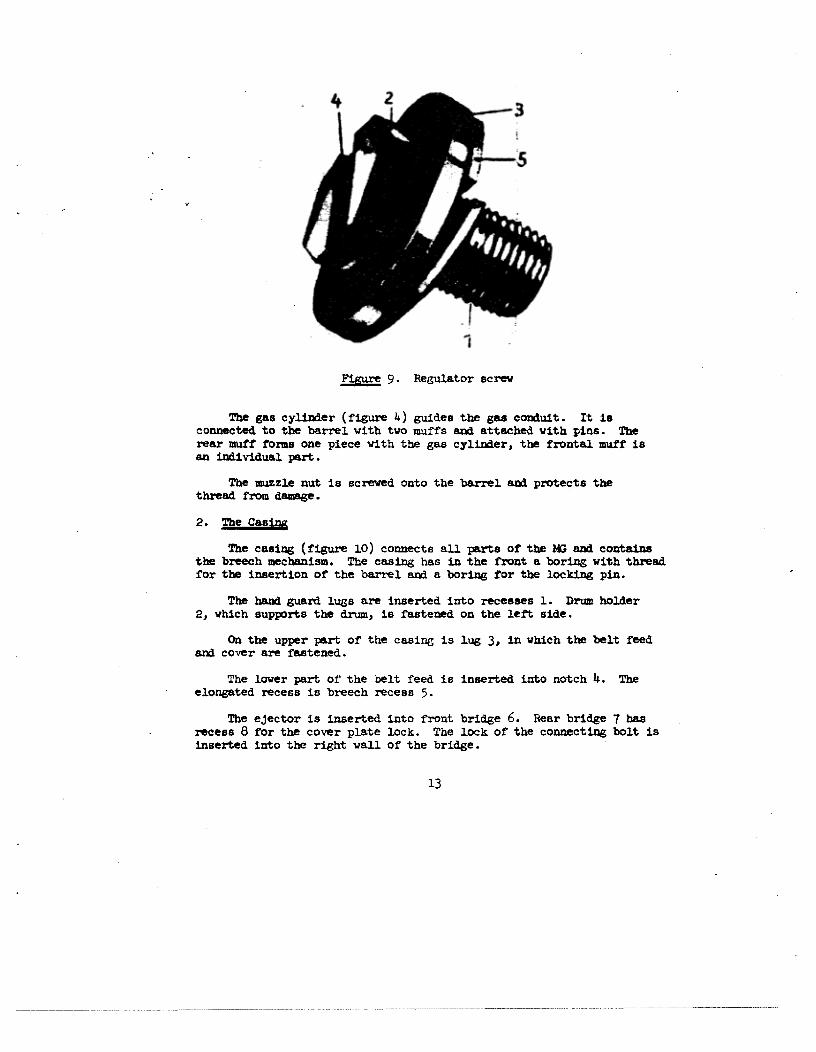
The gas c)r1i~ier(figure 4) guidea the gas Cozktult. It 18connectelto the barrel with two muffs and attached vith pins. Therear muff forms one piece with the gas cylinder, the frontal muff isan individual part.
The muzzle nut is screwed, onto the barrel aM protects thethreadfrom damage.
2. The CaBing
The casing (figure 10) connects all parts of the MG aM containsthe bzeeclz mechanism. The casinghaa in the front a boring with threadfor t~ insertion of the barrel aM a boring for the locking pin.
The haM guard lugs are Inserted Into recesses1. Drum holder2, whith supports the drum, is fastened on the left side
On the upperpart of the casinG is lug 3, in which the belt feedand cover are fastened.
The lover part or the belt feed is inserted into notch 1~. Thee1on~atedrecessis breech rece8s 5.
The ejector is inserted into front bridge 6. Rear bridge 7 hasreceasB for the cover plate lock. The lock of the connectthg bolt isInserted into the right wall of the bridge.
Flgtu-e 9. Regulator screw
13

At the right side i8 guide groove 9 for the cocking slide. Therear eM of the guide groove is videaed so that when the weapon isdiBaaaembled or asaetnbled, the cockir3�elide canbe removed~ze easily.
The casing has recesees on the inside, which acco~odatethe supportnxuutings during the locking of the barrel. The 1o~~1tidina1grooveslessenthe friction of the lock at the casingwall. e~take up thecern groove8 at the lock ~uide.
The ejector fastened in the casing ejects the cartridges. It isinsertedwith its dovetailed baae in t~ bridge and has a lug againstwhic1~ the cartridges strike ~Iuring the return ~v~nt of the breech.
The drum holder ho]it8 the drum to the casing. It has guide lugs
for the guide railB of the drum a~da drum lock.
On the upper side, the lock is coveredb~a plate.
14

Fjgure 10. Casing

3. The Bxeech Y~chaniem
The breech~,echanismclosesthe barrel tr~ the rear aM causestl~introd.iactlou ar4 iCnition of the cartridge as veil as the extractionax~ejection of the cartridge casesafter the firing.
The breechmechanismconsistsof the bolt assemblyaM the boltgu1d~az~d.the gas co~uit.
The bolt asBembly(figure ii) co~isistsof eb~ber1, two supportflaps 2, firing pin 3, extractor 4 with day and spring.
The cha~nber(figure 12) has in the front notch I for the bottomof the cartridge case, borehole2 for the firing pin, recess3 for theextractor with apring, 1u~L~to s~t‘it up on the bolt guide, expeller5 with nut 6 for the ejector; at the Bides it baa recess7 for thesupport rlap8, borehole 8 for the locking pin of the extractor; borehole9 for the locking pin of the firing pin.
The bolt assemblyis locked by the support flaps. The support flapshave 1u88 on the inside. These lugø hit the inclined planes of theanvil at the bolt guide ani presssupport flapa apart. The be~e1in~at the bolt guide closes the support flaps during the release,and thebolt asseu~b1yis unlocked.
16

Figure 12. Ch~ber
Figure II. Bolt Mechanism
17

The firing pin (fIgure 13) strikes the pereu~sioncap of t~cartridge. It iø divided into firing pth tip 1 and firing pinshaft 2. The tiring pin shatt has longitudinal ribs 3, ,which increasethe atren~thaM leBsen the friction surface• It also includes thebeveled aurracoof the tiriJ3g-pin locking pin.
The extractor draws the cartridge tro~nthe cartridge chamberaMholds on to it until it meetathe ejector. The extractor is spring-mounted.in t~ chamber.
The bolt guide (figure 14) contains the bolt aesemblyand Operatesthe feed mechanism.
On the upper site it has a notch for the in8ertion of the Bupportflap lugs, an opening2 for the csi-trid�e exit, anvil 3 aM roIl 4.On the lover part is a recessthat sere8 as a trigger guard. On t1~514e8 are guid~erslls 5, whIch glide in the guide groovesof the ca81z2�.The bolt guide has a three4 in the front for t~ insertion of gascozguit 6.
I
Figure 13. Firing piE
18

‘0
Figure 14 • Bolt - guide
4I

The bevelin�s at the z~otches cause the c1osin~of the suppoi-tflaps during the unlocking of the barrel. The anvil pressesthe supportflaps apart by means of the beveling, strikes the firing pin with thefront face and Bets the feed ~chaniam i~imotion with the roll. Theanvil baa a vertical boring, into which the axis of the roil is set.
The ~as co~1uitaete the bolt gtzl4e iii u~tionas soonas it ishit by the powder gases. It has a plate-like recessat the front er4that catches the powderç~ases• The rear end has a thread for theattachment0±’ the gas conduit to the bolt guide.
1~. Trigger Frame with Butt ath Grip
The trigger frez~ie with butt (figure 15) contains the triggerinstallation, limits the return motion of the bolt guide ai~ makes abetter haM1in~of the weaponpossible.
Trigger frame 1 has longitudinal rails 2 at ita upper part forconnectionwith the casing. The trigger inatallation fits into opening3. At its lower part, the trigger fraxue has two fully-pierced crossborings for safety mechanirnn l~aM the axis of trigger 5, plus triggerguard6 for the protectio~aof the trigger. The stocks are fastened tothe grip by screw 7~
At its rear end, the trigger fzra2ne e~4s as a block that limitsthe return movement of the bolt guide. The block has two posts 9with borings ror the connectingbolt; one boring for the pressingrod of the locking spring, aM an opening10 for the attathment ofthe butt. This openinghas on its lower part a longitudinal notchar~on the sid~esborings for screw U for the attacthnentof the buttto the trigger frane • At the left side of the trigger frame is theatorage space for the c1eanir~g rod.
20

Figure 15. Trigger fmanewith butt eM grip

The cockiz~gslide ia u~e~tto tigk~tenthe bolt aa~e~ib1y.It hasa cocking ~1ide strip with cockiz2g lug aM a folding cock~thggrip. T~cockix~geli4e has guide ledgesthat n1id~ein the right casirgvail.
The lockiDg spring bringB the g1id~ingparta to the i~stad.vanced.pOsition. It conaists 0t’ the spring aM the pressingrod.
The pzesein~rod ii CoDneeted vith the I.ocking øpz-ing aM aitBwith it. front eM in tl~ boriz~gof the bolt guide.
Butt 13 ia set with ita front eM in t~ openirzg of the triggerframe s~ is attachedby sciew U. On the inaide, th~b~xttbaa$boring into which tl~ plug for the Insertion of the locking sprtz~gtite,
a roceae for the insertion of the container with the acceesories.At t~ left aid.e i~ belt I~oklie.
5. The Trigger Installation
The trigger inate.Uat ion (fIgure 16) ia ~uuted. in the triggerfrw~*. It 1nc1~4eatrigger sear 1 with spring 2, trigger 3 with lockingpin 1~aM Batety mechanism5 with spring 6.
Tb. triggex seer keepsthe bolt guide in the i~at earwardposition.It h~nan opening for the trigger, a lug for the cozziectionwith thetrigger frame, aM a place for the spring.
22

Figure 16. Trigger mechanism
At the trigger are the lug, which enga�eathe ieceesin thetrigger sear, and t~ boring for the locking pin.
The aafety inecban1e~nputs the ~ at “sa~te.” The safety mecha~isi~baaa aha.ft axxt a ving. In the sb&ft 18 a recesa to supl,ort the safetyspring. The aatetymecl~anismIa held by the spring both in the safeaz4 activated poBttion8, The spring has a lug which engageBthe recessin t)~ trigger frei~e.
6. FeedMechanismwith Cover
The feed ~cbanis~n (figure 17) is actuated by the transport levertogetherwith the bolt guide. It teed.~ the cartridges contsiDe~tin theixtal belt in such a tannerthat they can be ejectedby t~ expeilerfrom the belt.
The reed ~chaz~iam includes upper part 1 of feed u~echnnia~n,lowerpart 2 of the feed n~chanim~aM casing cover 3.
The upperpart of the teed mechanism Is mounted on the cover. Inthe upper I1e.rt of the feed ~chanism, t~ belt feed. pavi iB insertedinto the guide groovewith a shock-mounted belt feed lever, and, theehock-i~unted.pressurelever iB attached there. The lugs connect the
23

upperpart of the feed ~chani~n to the caaing. The cover cloaeathe upperpart of the casing. A transport lever azx~a belt feetlever are n~uutedin the cover. The roller of the belt guide glid.esin the curve-shaped guide i~i1of the tranaport lever. The belt teed.lever is connectedwith tk~traz~B1~ortlever eth cauaesturing t~ torwai~aaxt return stroke of the bolt assemblyt~ latere]. ~ove~t of the belt-feed.
The lower pe.rt of the feed n~chnniam is inserted in t~ casingrecess aM is connectedwith the casingby r~ansof a lug. T~ lowerert of the feed. mechanism containaa sbock-zxniuted.belt-holding paw].,
a cartridge entry ath two dust-protection shutters. A boflow Blmftwith a cotter-pin connectstl~ feed. belt lever with the uppez pert ofthe feed.~chenis~ ar~the cover.
7. SIghting Mechanism
Sightir~ge~distax~cea&juatment are acc~p1iak3ed by u~an~of t~sighting mech~niam.It consists of the rear sight az~d. the muzzle sight.The night ing u~cha~i~u~(~gure18) includes rear Bight base1, rearsight leaf with spring 2, sight sUite 3 wIth ttunub nut ~ aal springs,rear Bight cam 5 aM adjustable BCZ~W 6.
The rear sight baseiB attached.to the cover. It has curve-fort~edclestø for the adjuBtu~ntof the rear sight leaf in accordancewithtt~ range, luga with borings ani openings for t~ luge of the rearsight 1ea~,aswell as a recess for the leaf-type Bpring.
2I~

1’)
Figure 17. Belt-feed with cover
I
1.

FIgure 18. Sightlug mechanism

The zs~Bight 1ea~hia lugs tor t1~coni~ctioziwith the rearsight be.se .M notches~or tbe Bight s]i4e On the rear sight leaft~s .cs.leujt~i graduAtionstx~ I to 10 (100 to 1,000in).
The 2*? sight lear has a lu� in the rear whosecy1ir~tr1ca1 crossdrtU bor1x~gis for the attachmentof the rear Bight cern ~th th~a&juatsblsscrev. On t~ upperaide tl~ lug hea crou-~il1d recessfor tb. zesi sigkzt caa aM in the rear s ecale ‘with sevengr~u&tionato both sides. The eeuter rk is d~±gnated“0.” One gredustionof the scale a~untøto 1.2 ; thia correspoa~.eto 2/1000 of therange.
Tbs lest-type ipriz*g bearaon the lower eat of tI~ rear eightleaf aM presseeit aga~1nztthe Blide rest.
3y ~ana of the sight elide the sight Ia adjuated to tl~ corxeapor~&ingrenge. T~ el,gkt Bli&e baa two thumb mrts with apringa,which keepit on the rear sight leaf.
The resr øight ca~lies In the boring of t~ iea~sight leaf luge.~can be Laterefly moved vith t~ ait~of tk~a&justab].e screw. By* latera]. ~ve~nt of tl~ rear ølght c~, lateral correction can becarTied o~xt.
T~~ove~nt of the sight notch by o~grathiation to the right orleft of the center i~rk of the acale correBpcL~.eto an a aberzstionof 2/1000of the re.r~e(i.e. at a &1ata~eof 100 ~ it ~unts to 20c~,at a dietsz~eof 200 ~ to ~O cm, etc.).
The auzzieaight (figure 19) has at its lower ea~.threM 1 to ~crevIn t1~~uzz1a sight protection. In the di~ter it has a 1ongitiaMn~1notch 2, to prevent a loosening of the muzzle sight of it8 ovn accor~t,The auz~1esight ha8 fist attachments3 on the top for t~ muzzle eightkey a~tsper5 to pin k, vbieh is used to 81g~Tt~n tI~ target.
The ~uz~1e eight protector (picture ~)) )~].dit~ auzzle eight,protects it against 4~i.gesnd sidB sig~xt1z~gin bright light. Themuzzl eight protector has 1ovet..iled exter8nic~1 for conz~ctiouviththe ~uzz1e sight bo1~er;oa top it has protective t1az~gee2, eM intk~c•ntr threaded boring 3 xtendiug $11. t~ Wft7 through for tbeinsertion of tbe muzzle sight.
At the front surface is a&juEtable ~tch I4~vh_ich during aightingis synchronized with a gmduationof the n~uzz1esight base.

Fic~ure1~. Front sight
Fi~~20. Front sight protector
2
28

8. The aa~Guard.
The heM guard (fi6ure 21) protectsageinnt burnE arid facilitatesthe hax4ling of t1~~G. It conaistaot two vood.en shells 1, whichare connectedby tour screws. The left sheU has boring 2 for thec1eaz2iE~rod.
9. The BiDOd
The bipod (figure 22) is~the front support of the )~duringfiring. It consistsof clamping foot 1, clamp 2, connection pin 3,two legs 4, spring 5 aM epring lock 6.
The bipod is attached to the barrel by a clamp. The recessesatthe clamp foot keep the legs of the bipod In a ready or rest position.
F~guxe21. HaM g~zard
29

Figure 22. BIpod
2
*
~—— I
II
V 4
—6
30

10. Dr’.*n with Belt
The drum is attachedto the dr~ho34er aM holda the ceztridge~Lt.
T~&r~ (fig~ue23) has caaing 1 anc3. cover 2. The drug cover iBattachedto the casingby hinge joint 3 and. iB kept cloeed by latch 4.The casingaM tk~ cover have ring-8baped ribs to iucxeasetk~irstability. The drum ce.ein~ha~guide reil 5 at the top, by which thedr~ ia attachedto t~ dum holder. At tk~dx~caaiz~gis an openingwith cover, fr~*twhich the cartzl.dgebelt ii cai~tuctdto the teed~chanis~, ~th grip 6 for carrying.
U. SpareParts ~M AcceBaozies
Every )~is equippedwith spare parts aM accesaorie5.
The ep~reparta are greased~,wrapped in oil p&per ar4 stored inthe units.
The acceesories (figure 26) includ.e:
The c1e~n(ng rod, the container for t1~acceBeoriesin vb~charecont~iz~e~the zegul&tor key, muzzle Bight ke~2, toggle 3 arid zeaz~r4 for c1e~ingthe gas routes, cartridge extractor 5, revolvIngclesniug attacb~nezrt6 and punch7. A3.50 i~1~z~MIn the acceaaorieBia a carrying strap, a covering for tk~)G a~.bagsfor the drwna.
31

w
FIgure 23. Druid
(~jU)
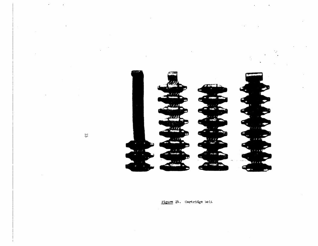
Figure 21k. Cartridge belt

Figure 25. Container for the accessories
34

3
~~re 26. AccessorIes

III. DISA5SE~Lfl~MW ASSE~1BLD~T~IF~
The L1~must be d.iaa8se~1b1edfor c1e~zxan~,for inspection, foroiling, for the excbA~eof parta aM for repair work.
In doing eo, the roUovi~gis to be obser.~e~:- The Z’fl ~nuetbe d1aassemb1e~iand assembledon a table, or, if
in the open country, on a cleaxi fouthation;- only s8.tisfactory accessoriesare to be used for disassembling
aM asBeTablinc;- the parts n~unt be detached cM attached without usingnxu~hforce;- screws must be loosened,first with the screw driver cr~then
re~novedby baz4;- in asetnb1iz~g,attention must be placed.on the numbersof the
parts to avoid a mix-up with parts of other I~s;- the il~muat be disassembled,cleaned., oiled anct assembled
only untler super ision of the croup leader;- bofor~disasse~nb1ing,the i~Z}must be unloaded;- a difference tnaat be uzacle betweenpartial aM completeassembling
eM d.isassemb1ix~g.
12. Partial Diegsaembljng aM £aaeinbling
Before disaseemb1in(~,the ~ gust be placed.on the bipod. The
?.fl is dieaseeuibledin the t’oilowing manner:
1. Detechthe cleaning rod:
Grasp the cleaning rod with the left huM, ~noveit off to thatextent that tk~head 0±’the t~1enn(n~rod eu~ergesfran the recessin tk~tzigger frame. Grasptt~ cleaning rod at the head aMdzuv it fz~ its atorageplace to the rear.
2. Rat~veContaii~r with acce8sories:
Presswith the right thwab on the block of the butt plate, turnthe cover with t1~left bai~to the left or right (a quarterreiolutibn), lift the )G at the barrel ath remove the accessoriescontaineir from t1~recessof the butt.
3. Openthe casing cover:
Grasp tk~ neck of the butt ‘ulth the left hand, move the coverblock with the right haM rorward to the stop ax4 lift thecover to the extent that the spring block 1u~of the belt feedreache&behind the caain,j 1u~(in an opened position, the cover~uat be held by the spring block).
36

1~,. Remove the breech-closingspring from the butt:
Support the MG with the lett haM at the neck of the b~rtt,press the right thumb or the screw driver on the head ofthe breech-closingspring block aM turn it a quarterrevo1tr~ionto the left. Then reu~vethe breech-c1oain~spring.
5. Remove the trir~ger frame from the casing:
Pushout t1~connection pin with the pu~hto the right untothe atop. Grasp the bath guardwith the left haM ax~theneck of the butt with the right han~1~4 remove the triggerfrw~etoward the zear.
6. Detachthe cockjn~slide:
Grasp the h~x~guard with the left haM, wltMxav the cockingslide with the right haM to the en1arg~nentof the c~xtoutofthe guide ~ai1 in the casing axx3. re~vetoward, the right.
7. Remove the breechc~cbanism:
Withdraw the bolt guide with the right index finger from belowstill farther, grasp it with the right hu~ai~pull it out ofthe casing to the rear.
8. Detach the bolt assembly from the bolt guide:
Hold the bolt guide in the left haM, lift with the right 1ia~dthe bolt assemblyfrom the bolt guide aM remove the supportflaps from the bolt assembly.
This conc1~zIeethe partial diaaseeinb~yof the 14G. It it re-asse~b1edin reverseorder.
37

Figure 27. Opening the casingcover
38

28. TakIng the main spring out of the butt

Fi~ure29. Removing the trigger frame from the casing
4:a
—~ ..
:: ~::‘— •~ “. 0~ ..#_~b½t — —-

I—.
Figure 30. Taking the cocking slide out

13. CompleteDisassexnb1in.~and Asse~nb1ingThe cc*nplete disassemblirw~or the 14 is the continuation of the
partial disassemblingand isto be carried out in the following order:
9. Disassemble the bolt assembly:
a) Removet~ extractor fr~ the bolt assembly:Place the breech n~chenismin such a manneron woodenblocksthat the locking pin gets to lie betweenthe blocks; knockout the locking pin with punch and. ha~~r;take the bolt as-sembly into the left hand, press with the tht~nbthe extractoragainst the recessand dzaw out the punch fran the boring forthe locking pin; remove the extractor, the block and the springof the extractor fr~ t1~bolt assenib3y.
b) Remove the firing pin:
Piece the bolt assemblyIn such a manneron the woodenblocksthat the 1ockir~pin gets to lie betwen the blocks; knockout the 1ock1n~pin with punch and hazm~er;remove the flrin~pin fran the boring ot the bolt asseE~b1y.
10. Take off the Regulator:
Unscrev the regulator screw about two or three revolutions withthe key, move the regulator to the right and hit with the malletthe head of the regulator screw; hold the regulator at the cir-cular track, unscrewt1~screw cc*npletely by hard and remove tI~regulator.
U. Disassemblethe Belt Feed
Press in the spring bolt of the hollow axis below the upperpartof t}~ telt feed with the regulator key, close tI~ casingcoverand extract the bolt upward with the regulator key; open the cas-ing cover, hold, the hollow axis fran below with the left hand,force the punch into It and detach it, seizewith t~ left handthe casing behirki the dr~ holder, graspwith the right hand, theopen casing cover and drew it off fran the upperpart of the beltfeed toward the rear; shove the belt feed pay?toward the leftout of t~ guide groovesot the upperpart of t~ belt feed, presst1~ring lug of the transport lever out of the boring In the coverwith the thumb or a screw driver, take the cover into the lefthand and pressthe retaining spring with the thumb toward tl~cover; seizewith the right hand tk~transport lever ar~removeit fr~i the axis.
42

I
31. Remov1nj~the bolt mechanism
-

Figure 32. Detach1n~the bolt mechanism frotn the bolt guiIe

Figure 33. Taking out the locking pin of the extractor
Figure 3l~. Ren~oving the extractor

~gure 35. DetachIngtl~ regulator
46
,.I.

-4
Fij~~36. PressIngthe spring bolt in with the regulator key

co
F1~ure 37. Removint3 the casing cover fr~ the upperpart of the belt feed

\0
Fi&ure 38. Taking the transport and,belt-feed pay], levers out of’ the casing cover
1•.
IL’ ~tiI?’

Move both levers to the right and take them out of the ~cver;separatethe belt-feed p~w1lever and the transport lever; knockout tie belt feed 1ock1n~bolt with punch and ha~m~ertoward theright and extrect the upper and lower parts of tI~ belt feedfr~ the caain~in an upward direction.
]2. Unscrew the Hand Guard.:
Loosent~ four connecting screwsvith the screw driver of t~regulator key and remove both parts of t1~hand guard.
This termthate& the c~ip1etedisassembling. The assemblingtakes place in reverse order.
Note: My further ~isasse~nb1ingof parts is perniitted only inthe ordnance uiachine-shop.
lh. Disaesembllngand Aaseznblin& In the OrdnanceMachine-shop.
1. Diaa8aemble the trigger installation:
Shift the s&tety wing forward, i.e. put the W~at “sa1~e;”placethe trigger fr~ on two woodenblocks in such a mannerthat t1~locking pin of the trigger Is lying betweenthe blocks; knock outthe locking pin with punch and hanm~rand take out the searandthe sear spring; take the punch into the right hand and presswith the thin end o~the punch on the rear end of the retainingapring, grasp the retaining spring with the left thumb and indexf1n~er arid take the safety device out of the boring of the triggerframe.
2. Aoaemble t1’~trigger installation:
Take the retaining spring Into t~ right hand and place Itthrough the round recessinto t~ groove of the trigger frame;place the end or the punch into the boring of the retaining springand push the spring into the most advancedposition; press the endof the retaining spring with the thin end of the punch into thegroove bottcri In the trigger frame; shift t1~esafety wing to therear, and p1a~ethe retaining spring into the round recessof theblock in the trigger fra~ne,place the trigger spring with theright Index finger in t~ block of the trigger franz and pressont~ trigger lever (in doing so, the latter must descendslightly);~h1ft the safety winG forward; hold the searwith the left hand,Insert fr~ below the trigger with the right hand and, connect itscam with the lug of the recessat the sear; take the trigger frame
50

in the left ham~,hold. t1~sear with the th~ib and the triggerwith t~ index finger so that the borings are facing each ot}er;Insert with the riCht hand the 1ockin~pin of the trigger; driveit in vith a cop~r1i~~rend center punch it; shift the safetyvin~~to the rear.
3. DIsassembling and assexnb1in~~he si~htingmechanism:
Pushthe sight slide to t1~rear~hold the rear end of’ the rearsight leaf with the left hand, press the front end of the sightleaf onto the rear siGht base with the screw driver In the righthand, push the rear ~1ght leaf back with the left hand and takeIt off fran the rear sight base; lift the front end of the retain-ing spring In such a mannerthat tl~ retaining lug of the springe1~rgesfrcin the recessor the rear sight base; press down thethumb nuts, pushthe sight slide to the front end and remove Itfrczn the rear sight ietI; release the thumb nuts and remove themwith the sprint3 fran the hor1nc~sof the sight slide; place thesight leaf on a wooden block in such a mannerthet the pin of’ thead.justablescrew is at the side; knock the latter out with punchand haz~ner;unscrew t~ roUer fran the adjustablescrew; removethe adjustable screw vith the rear sight cern fr~ tk~ lug boringof the rear sight leaf. The assemblingof t~ sighting mechenisxntakes place In reverse order.
J~. Remove the muzzle sight protector and tI~ muzzle Bight:
Locsenthe nut of tie muzzle sight retaining screwwith theregulator key by two to three revolutions and then unscrewthescrew by hand; knock out t~ muzzle sight protector fran thegroovesof the muzzle sight holder.
The insertion of the muzzle sight arid, of tie muzzle sight holder
is carried out in reverse order.
5. Remo’ire the biped:
Knock out the retaining pin of the clamp on one side with punchand hammeran4 open up the clamp. After the mounting of themuzzle sight, t~ firing accuracyof the W mustbe re-examined.
51

f~)
39. RemovIngthe 1ockin~pin of the trigger

‘.Jt
id/I
_____ 1~O. Removing the safety device

pr
3:-
~gure Ui. Inserting the retaining spring

14
I,
14V
55

,,
-
I
r
0’~ -1
Figure 1~3. Detaching the rear-sight leaf

-4
~~ure ~ Detaching the leaf-spring
~1)p

IV. INIT~RACTIONOP TI~PARTS ZZJRI!~GflRING
The ?~VIs loaded and secured. The breechblock is in the most rear-ward position and is held by the sear, tie main spring is pressedtogether. The safety wing is shifted to the front, the round partof the safety has placed itself under the sear and preventsduringthe operation of the trigger the lowering of tie sear. The filledcartridge belt is inserted. in the feedmechanism. During .t}e shift-ing of tie safety wing to the rear, the safety shaft is turning, andthe flattened, part shows upward. The operation of the trigger pressesthe trigger cam on tie trigger recess, which is lowered by the liz-pact. The bolt assembly is thus freed and shoots forward by theforce of the tightened main spring. The roller on the anvil of thefeed mechanismslides in the curved guide rail of tie transportlever and presses it to the right. By the mortise-and-tenon-jointof the transport lever with the belt feed paw],, the right-sidemovement of the transport lever is changedinto the left-side move-ment of the belt feed pawl lever. Tie belt feed pawl lever, whichwith its front part is operating the belt feed pavl, presses thelatter toward tie left. Tie belt-feed lever, which is shock-mountedin the belt feed pawl, is pressedupward, glides over the next linkof the cartridge belt and then places itself behind this link. Thebolt assembly contirnes to glide forward. The expeller pushestiefirst cartridge out of the belt and leads it into the barrel. Thebolt assembly strikes the breech piece arid the extractor claw fastensitself in the ring nut of the cartridge base. The guide of the boltassembly contintes to glide forward. The beveled surfacesof the an-vil press the support flaps apart, which then place themselves inthe recessesof the casing and lock the barrel fran tie rear.
The front surface of tie anvil strikes the firing pin, whichwith its tip enters through the front wail of the chamber and hitsthe percussion cap of tie cartridge. This starts the firing. Underthe pressure of the powder gases, the bullet leaves the barrel withincreasing velocity. After tie bullet has crossed.tie gas conduit,a portion of the powder gases is diverted to tie regulator. Thepowder gases are passed on by the regulator to the gas chamber andare pressing on tie front surfaceof the gas piston. Tie pressureon the gas piston is transmitted to the bolt guide and the boltguide starts tie return motion. The recess in the bolt guide, inwhich the lugs of the support flaps are placed, draws the supportflaps together; the support flaps leave the recessesof the casingand the barrel is unlocked. The breech mechanism glides back andthe extractor draws the cartridge case fron the cartridge chamber.The ejector, which glides in the groove of the expeller, strikesthe cartridge case base and expels the cartridge casedownward.
58

S
The roller on tie anvil of tie bolt guide pressestie transport leverto the left. The transport lever transmitsthe left-side movementtothe right-side movement of the belt-feed pew]. lever, which pressesthe belt-feed pawl to the right.
The belt feed lever, which during the forward glide of the boltmechanismhas placed itself behind tie next link ofthe belt, pushes
the belt one link to the right. During this movement, tie belt -feedguide is presseddownward and the pressurelever upward, which thenduring the return movement place themselvesbehind the next belt linkand the projectile respectively. The next cartridge is thus above theopening of the lower part of the belt-feed.
The bolt mechanism continues to slide back andpresses the mainspring together. The further return movementof the bolt mechanismis stopped by the block of the trigger frame.
This procedure continues until tie trigger is released, tie seargoes upward and the trigger cam of the bolt guide catches itself be-hind the sear.
59

Pi~ure145. Position of the Pt) parts prior to loadth~ 1 - P~inspring; 2 - main spring block; 3 - cleaningrod; 14 - cover-plate lock; 5 - cuing cover-plate; 6 - transport lever; 7 - belt-reed pawl lever;U - eJector; 9 - belt-feed pawl with belt-feed lever; 10 - prssw’e lever; 11 - connecting lug;12 - barrel; 13 - gas conduit; 114 - regulator; 15 - gas chamber; 16 - gas cylinder; 17- ex-tractor; 18 — belt-feed guide; 19 — bolt mechanism; 20 — bolt guide; 21 — safety device; 22 -
sear; 23 - trigger; 214 — support flaps; 25 — firing pin.
T7.: -..-—, P
5
-‘~ .~.

Z~&~i46. Position of the Ml parts aft.~ lcadingt 1 - Ilath sp~ing; 2 — cleaningrods 3 — cover—plat, lock;14 - cuing cover—plate; 5 - transport lever; 6 — belt—teedpaul lever; 7 — belt—t.sdpil withbait—feed lever; 8 — pressiw. lever; 9 — ger conduit; 10 — regulator; 11 — gasc)~sr; 12 —
gas piston; 13 - extractor; Vs — bolt mechanhsa; 15 — bolt gui4e; 16 — Usar~ 17 — triggers18 — tiring pIn; 19 — support flaps; 20 — drr; 21 — cartridge.
~1~i 47. Pos~.Lionof t.lte l~part~~&hortly before the dischargeof the sbot* 1 — )~Inspr2ng~ 2 —
‘~ov-p1i~t~ 3 - “raneport levr~ 14 — belt-feedpaul lev.rs 5 — ejector; 6 — belt—teedpssl~tit~.bolt—teed i,v~r, V — preu~m’elever; 6 ~az conduit; 9 — regulator; 10 — gas ob~srjU ~ai~ pt~tot~ .~ Qxtractor; 13 — bolt ~~han1sm; 14 — bolt g4tEa; 15 — safetyd.vboe;16 — i~ar, 17 . trigger; 18 support flaps; 19 — firing pin; 20 — drtsa 21 — cartridge.
a
I-’
,I 4
I it
II-~.f5

V. ¶~CIINICALUISPECTION OF TI~I~
Technical inspections have to be carried out in accordance with thetix~sprescribedin the garrison duty regulations. Tie technical con&i-tion is determinedin accordancewith the degreeof readiness for actionof the *~.
The ~Elmust be examined daily before training, before end after fir-ing andduring the cleaning of the weapons.
The daily inspection of the l~ is carried out in the assembledanddisassembledstate.
The accessoriesare to be inspected prior to each cleaning of tie )‘fl.The machine gunnermust report to his superior inmediately all deficienciesdiscoveredduring the inspection of the W and of the accessories.
15. Daily inspection of the Ik&~
It must be checkedduring the daily inspection to determine:
-- whether there are cracks, dents, rust, di.rt, deepscratches onthe metal parts or cracks and impact places at the butt or atthe hand guard;
- - whether threadsare torn off or stripped;
- - whether the moving parts, the main spring, the trigger installa-tion, tie safety mechanism and, the feed mechanismare functioningfaultlessly;
- - whether the muzzle screw has been threadedon and is firmly at-tached on the barrel;
-- whether the easing cover is held. firnly in both openedand closedposition;
- - whether the indentation at the front sight protection agreeswiththe indentation at the front sight baseand the adjustmentof thesight notch agrees with the zero graduation at the scale;
-- whether the accessoriesare in a satisfactory condition, are wellarranged in the container, are in the recess of the butt, andwhether the cleaning rod is at the right place;
- - whether the sling hooks and the bipod are firmly attached and thecarrier sling has been connectedcorrectly to the hooks;
62

- - whether the drums and belts are in order and tie drtmis are firmly
attached to the ~}.
16. Inspection of tie I1~in the assembledstate
On this occasion it must be checked to determine:
-- whether the eerie). zumibersof the parts agree with each other;
-- whether the muzzle sight is straight, is placed firmly in theboring of the muzzle sight protector and doesnot shift duringfiring;
- - whether the muzzle sight protector sits firmly in the muzzle sightholder and cannot be moved by hand;
-- whether the rear sight leaf returns to its former position whenit is pressedto the side;
-- whether the sight notch sits above the-center mark of the scalewith the figure ~~Ottand moves laterally during the turning ofthe adjusting screw;
-- whether the sight slide can be moved steadily and easily on therear-sight leaf and is sitting firmly at each calibration;
-- whether the underside of the rear sight slide is attached firmlyto the slide support;
- - whether the leaf spring holds the flap firmly in the correspond-ing position. Tie legs of the bipod must be kept in a spreadposition by the spring andmust not be able to turn to the frontor rear;
-.- whether the legs of the biped are held in a rest position by thespring pressurepiece and are attached. by the pins that are engagedin the clip foot;
whether the regulator is firmly held by the screw in the connect-ing piece and is accurately adjusted;
- - whether the drum holder is bent and the drum block is under spring
pressure;
-- whether the trigger frame is firmly attached to the casing;
- - whether the cover lock can be freely moved forward by hand pressureand quickly moves backward underpressure by the spring afterrelease and whether it holds the cover with the notch firmly in
the closed position;
6.~

-- whether the spring lock of the upper part of the feed mechanismholds the cover securely after it has beenopened;
- - whether the cover of the butt plate is firmly attached to thebutt plate and can be easily turned. The lock must reach outabove the surface of the plate, must easily be pressed in withthe finger, and must keep the cover firmly in a closed position;
- - whether the accessories are couplete and are accuratelyarrangedin the container;
- - whether the cartridge belts have rusted, bent or cracked linksor defective connecting springs;
- - whether the drum can be easily openedand can be attached anddetached from the drum holder.
During the inspection of the )4G in the assembled state, the function-ing of the gliding parts and of the trigger installation and of the safetymechanismmust also be checked.
On this occasion:
-- tie lock at the cocking slide must be pulled backwards to thestop; the movable parts must move easily and without restraint;the lock must remain in the extreme rear position;
-- the safety wing must be shifted forward; it must remain in themost advanced position;
-- the trigger must be operated; the bolt must remain in the ex-treme rear position;
-- the safety wing must be shifted to the rear; it must jump to theextreme rear position and must engage firmly;
-- the trigger must be operated; the bolt must snap forward force-fully and without restraint (the trigger must be easy to operateend must snap back to its original position when released);
-- the ~& must be placed in a perpendicular position (barrel upward),the cocking slide must be pulled so far to the rear that thefront surface of the gas piston is in line with the rear sectionof the gas chamber; then release the cocking slide; the boltmust snap to the extreme forward position.
Checking the function of the feed mechanism
- - Open the casing cover;
64

- - press the transport lever at its rear end to the right up to thestop; then release quickly (repeattwo three times); bothlevers and tie feed belt pawl must move easily and must return
after release with a forceful movement to their initialposition;
-- close the casing cover;
-- load the It with 5 to 8 thmm~rcartridges;
-- operate the trigger; during the forward movement of tie bolt,the lock must push the cartridge easily fran the belt to thecartridge chamber;
-- bring the bolt mechanismagain to the extreme rear position;during the return movement, the cartridg~must be pulled out bythe extractor and after the impact it must be thrown onto theejector. The next link of the belt with the cartridge must bebrought by the feed mechanismover the cartridge dischargeofthe lower part ofthe feed mechanism. (This proceduremust berepeated until all cartridges havebeenejected from the belt).
17. Inspection of the lit in the DisassembledState
The inspection of the It in the disassembled state must take placein the presenceof the squad leaderor platoon leader. Prior to the in-spection of the disassembled It, all parts have to be cleanedand dried..During the inspection, each part must be examined and, attention must bepaid that all numbers of the parts correspond.
a) Inspection of the barrel
The barrel must be held at eye level and turned against a lightplace; it has to be looked through from the muzzle and then fromthe certrid~e chamber. The barrel must be turned around its axisend be kept at a distance of fran 50 to 70 me fran the eyes. Dur-ing the inspection of tie bore, the follas4x~can be detected:
Formation of rust as a brown coating at individual places or in
the entire barrel.
Copperplating in the form of a reddish coating in the barrel.
Wear and tear of the 1an~~,especially at the beginning of the
grooves and at the barrel muzzle.
Bulging of the barrel, which appears in the form of a shadowtransversering.
65

Barrel warping, which can be detected by a special shadowforma-tion in the barrel (figure 148).
In order to be able t~odetect barrel varpings, the barrel mustbe directed to the horizontal lower edge of an object (windowframe, blackboard, etc.). In a straight barrel, one seesashadowin the form of an equilateral triangle. The form of theshadowtriangle must not changeduring the rotation of tiebarrel.
In a warpedbarrel, the sides of tie triangle are warped end undergoa changeduring the rotation of the barrel. If the warping .of the barrelis excessive,the shadow triangle is interrupted, or the sides are shifted.
The ‘internal surface of tie barrel is chraneplated.. Chromium-platedbarrels have special characteristics which, however, have no influence onthe combat properties.
Thesepeculiarities are dull sliding surfaces, ring shadows, spiralstripes on the chromium-plated surface, powder network and breaks in tiechranitmi.
66

Figure 14.8. Shadowtriangles in the borea - in a straight barrel; b - in a warpedbarrel.
67

Dull sliding surfaces, ring-shadow and spiral stripes can occurin new and used.barrels.
In chromium-plated rifling met-shapedbarrel erosion and, scalingof tie chromium are unavoidableand are not defects, for thebarral maintains its accuracy of fire.
Barrels with net-shapedbarrel erosions mustbe carefully cleaned.
b) Inspection of tie bj~ end its attachumnt to the It
The bipod must be firmly attached to the barrel andmust turn inthe clamping collar. Tie legs of tie bipod must not be bent; thespring lock must keeptie legs firmly togetherin the folded state(marchingposition).
c) Inspection of tie casingand. of tie belt-feed
The casingmust be firmly connectedwith the barrel, and tieejector must be firmly inserted in the bridge.
Tie drum holder must be firmly attached to the casing andmustnot be sha1~y;tie connectingbolt must be securedagainstdrop-ping out by the lock in the boring of tie casing.
Tie upperand lover parts of the belt -feed must be firmly con-nected by tie axis.
The lower pert of the belt-feed must sit firmly in tie recessoftie casing, must not have any loose rivets, and the recoil guardmust not be bent.
If tIe belt-feed guide is pressedwith the finger, it must compressand must square off with the lower part of tie belt-feed. If re-leasedit a~1stmove upward forcecully under the pressureof tiespring tension; tie belt-feed. paw]. must forcefully glide in tiegroovesof tie upper part of tie belt-feed; the belt-feed. andbelt-feed lever must be under spring pressure.
d) Inspection of the handguard
The hand guardmust be firmly attachedto the It. The screws oftie hand guardmust be screwedin until the stop, and must not t~wn’togetherwith the nuts of the left half of the hand guard.
Tie overlays must lie closely to the inside and. outside of thehand guard, and the punched-outshouldersof the overlays mustnot be pressedin; tie nuts must be firmly in the openingsofthe hand guardsides.
68

e) Inspection of the bolt mechanismand,of the main spring.
Wear and, tear of the front surfaceof tie bolt mechanismareadmissibleonly when the extractor claw during the return movementof the lock holds the cartridge case; tie support flaps mustnot ‘wear out; the firing pin must move freely in the chamber;when force is applied with a finger against the rear end of thefiring pin, the firing pin tip must enter through tIe front wailof tie chamber; the locking pin of tie firing pin must sit firmlyin the boring andmust not slip out; tie extractor must be pres-sed by the spring; the locking pin must sit firmly.
The bolt guide must not have any cracks, bent placesor dents atthe guide rails or wails; tie roll must sit tightly on the axisand must freely rotate on it. The axis of tie roll must be firmlyinserted in the boring of the anvil of the bolt guide.
Tie gas piston must be connected,with the bolt guide (a slightplay is admissible); the locking pin of tie piston must sitf lrm].y in tie boring and is not allowed to protrude.; the pistonmust go freely into tie gas-chamber.
The main spring must be connectedwith the pressingrod and itmust be possible to set it easily on the block. Tie coils oftie spring must not be bent.
The pressing pin and the block must not be bent end must sitfirmly in the slide lock of the piston.
f) Inspection of tie tri~er frame with piston and trigger installation
Tie safety device must be held by the safety spring in the forwardand rear positions. If tie safety wing is shifted forward, thenthe sear nosemust not lower itself during pressureon tie trig-ger. If the safety wing is shifted to the rear, then the sear nosemust lower itself during pressureon the trigger. An insignificantrounding off of the sear nose is admissibleif tie bolt guide isheld in the extreme rear position. Tie locking pin of tie triggermust be firmly set in tie boring and. must not shift; the gunstocks must be firmly attached to the frame; tie connectionofthe trigger frame with the piston must not be loose.
g) Inspectionof the casing cover
Tie axis of the belt-feed paw]. guide, tie rivets of tie transportlever spring and tie rivets of the rear sight baseon the coverare not permitted to be loose.
69

The rivets at the cover lock also are not allowed to be loose.The cover lock must be freely movable on the cover andmust beunder spring pressure.
The cover lock screw must be firmly screwed into the guide rail
of the cover and connect the cover ],ock with the cover.
h) Inspection of the accessories
The accessories must be complete; the oil canmust be filledwith oil; the cleaning rod must not be bent and tie thread notworn; the regulator key must haveno cracks end broken places.The blade of the screw driver must not be broken; the frontsight key must have no cracks or dents. The reamerfor thecleaning of the gas routes must have rio damagedteeth; tie ex-tractor must have no i&entatiam at the ring-shapedshoulderofthe split tube the cleaning rod top must turn itself with itsrevolving part around the shaft and must have no edges; the punchand the toggle must not be bent. The accessoriescontainer musthave no dents at the casing and cover; tie cover must in theclosed state be locked by the block.
The muzzle cap must have no dents and torn-off threadsaroundthe entrance opening for the cleaning rod; the oil can must haveno dents or cracks at the casing; the oil can must not loose anyoil through the plug or through its scans; the covering and thebøga for the drums must be dry and clean.
70

VI. PR1~PARATIONOF PI~I1.t FOR P’IRIi~
The M~must be preparedas follows:
-- The )fl must be inspected in the disassembledand assembledstate;
-- belts, drums and cartridgesmust be inspected;
- - belts have to be filled with cartridges and placed in the drums.
During the preparation of the ?~for firing, the drum with the filledbelt must not be attached to the )t~ it must be attached only on the fir-ing line, shortly before firing.
Ismiediately before the firing, tie barrel must be dried end the may-ability of’ the gliding parts mustbe examined.
After firing, the ~ must be unloadedand inspected. Loaded WP smust not be left at the firing line.
The M~must be disassembled,assembled, cleaned,oiled and inspectedstrictly in accordancewith tie correspondingsections of this regulationon],y.
18. Belting of the cartridgesand insertion of the belt in the drum
Before filling tie aninunition belts, inspect the cartridges. If thebelts are defective, they must not be filled with live cartridgesor withdrill or blank cartridges.
The cartridges must be placed in the belts as follows:
-- Take the belt into the left hand in such a way that the openingof tie links point upward, the directional attaclunent to thefront, and the traversingstop to the rear;
-- shovethe cartridges into the belt links from the traversingstopswith the cartridge points forward to such a degreethat the tra-versing stops snap into the circular groovesat the cartridge casebottom;
-- if less than 100 cartridges are to be filled into tie belts, thefilling will have to start at the connecting piece or last link.
71

Figure 1~9. Placing cartridges in the belt
72

Figure 50. Correctly-filled cartridge belt

If single rounds are to be fired, live and drill cartridgesmustalternatinj3],ybe placed in the belt to avoid stoppages. (The last car-tridge must be a drill cartridge).
Two belt ends are to be connected as follows-:
-- Take the belt end with the connection piece into tie left hand andplace with the right hand tie connection piece of the first beltend. through the large opening into tie connection link;
- - Shove with one finger of the left hand the connectionpiece fromtie inside ~n such a manneragainst tie connection link that theconnection lug snapsinto the small opening of the connectionpiece;
shove one cartridge into the connection piece. -
Figure 51. Connectingtwo belt-ends by meansof theconnecting link and the connecting piece.
71~

Figure 52. Inserting tie cartridge in the connectinglink
The filled belt is to be placed into the drum as follows:
-- Openthe drum cover;
-- roll tie belt, starting from the last link, in such a mannerthat
tie open sides of tie links point inward;
-- place the rolled-up belt into tie drum in such a way that the
projectile points are directed towards the drum bottom;
-- draw tie belt endpiece through the window of the drum towards
the outside;
-- close tie drum cover and secureit by tie lock.
- 75

Figure 53. Placing tie filled belt into tie drum
19. Adjustment of the regulator
With WPs that are delivered by the factory (warehouse),~ie regulatoris set for averageadjustment, i.e • the lock of the regulator sits in recess2 of the regulator rim.
After the firing of about 1,000 to 1,500 rounds, the gliding parts arewell run in, and tie force of the recoil becomestoo great.
Tie regulator is to be adjusted to the s”~l1~stgas conduit, i.e • recess1 at tie regulator rim is to be brought in agreementwith the regulator lock.The largest conduit of the regulator is used when tie movable parts aredirty and when there is no possibility to clean them, or during firing atlow temperatures.
The regulator must be adjustedas follows:
-- Loosenthe regulator screwwith the regulator key by about two or
threeturns;
-- loosen the rim of the regulator fran the lock;
-- presstie regulator out toward the right andmake the desiredagreementcorrespondwith the lock;
-- pressthe regulator toward the left and turn the screw again upto the stop.
II
76

Figure 51~. Adjusting the regulator

VII. HANDLING OF PH! UG IN PH! FIRING PC6ITI0t~
20. !mp~Lacementof tr4e L~G
The )G must be set up in the firing position in the line ofof fire. The end spurs of the bipod must be sunk into the ground.This gives the )G a firmer standduring firing and it obtainsadirected recoil.
However, the bipod must not be dug in, for this impairs theaccuracy of fire.
21. Ad~uatmentof the sight
The thumb nut of the sight slide must be pressed together withthe right thumb and index finger, and the sight slide must be shiftedon the rear sight leaf to the corresponding scale division.
After that the thumb nut must ~e released and it must be verifiedwhether the slide remains at the set distance. -
After the adjustment of the sight, the adjustment of the sightnotch must be checked. If the sight notch is displaced to the side,it must be placed on “0” by means of the adjusting screw. Whenfiring with a strong side wind, adjust the sight notch opposite thedirection of the wind.
If the sight notch is displaced by one scale division, the meanpoint of impact shifts with regard to the point of aim by 2/1000 ofthe firing distance.
Table of the Lateral. Shifting of the SightNotch in Scale Divisions
(The wind is blowing at an angle of 900 to the direction of fire)
Wind velocity
Ins/sec 1~ 6 8Range in a Adjustment in scale divisions against
- the direction of the wind
100 — —
200 1/2 1/2300 1/2 1
1 2
78

.300 1 2 2600 11/2 2 3700 2 3 14Boo 2 31/2 141/2
22. Loading the LG14
The M can be loaded with open or closed casing cover.
With closed casingcover, the 10 can be loaded only if the beltis filled completely with cartridges.
a) Loading the 110 with closed casingcover
Let down the tightening handlewith the right thumb.Grasp the tightening handlewith the right band and draw itback to the stop. (Bring bolt mechanismto the extreme rearp~aition). Shove the cocking slide forward and let itengage in the holding recess; shift the safety wing forward(the 10 Is on safe). Grasp the 10 with the right hand atthe small of the stock and lift it somewhat; take the drumwith the left hand in such a way that the carrying lug pointsto the left; shove the drum with the guide rails on the drumholder; shift the drum stop downward; stick the end pièceof the belt from the left through the notch of the belt—feed;graspthe end piece with the right band and draw it towardthe right unto the stop. The 10 is loaded and secured.
Figure 55. Attaching the drum to the drum-holder
79

g)
Figure .36. Securing the drum with the drum lock

500 1 2 2600 11/2 2 3700 2 3 14Boo 2 31/2 141/2
22. Loading the LC~4
The ~ can be loadedwith open or closed casing cover.
With closed casing cover, the 10 can be loaded only if the belt
is filled completely with cartridges.
a) Loading the 110 with closed casing cover
Let down the tightening handle with the right thumb.Grasp the tightening handle with the right hand and draw itback to the stOp. (Bring bolt mechanism to the extreme rearposition). Shove the cocking slide forward and let itengagein the holding recess; shift the safety wing forward(the 10 is on safe). Grasp the 10 with the right hand atthe 8msll of the stock and lift it somewhat; take the drumwith the left hand in such a way that the carrying lug pointsto the left; shovethe drum ‘with the guide rails on the drumholder; shift the drum stop downward; stick the end pièceof the belt from the left through the notch of the belt-feed;grasp the end piece with the right band and draw it towardthe right unto the stop. The 10 is loaded and secured.
Figure 55. Attaching the drum to the drum-holder
79

Figure 56. Securing the drum with the drum lock

cn
Figure 57. Loading the IC with closed casing cover-plate
~‘,“ %__‘ .~..a._ .‘ ‘.. ~—t.. ~t*-~

Figure 58. Loading the IC with Opened casing cover-plate
82
- -‘ - -

b) Loadingof the 10 with open casing cover
Cocking sad securing, as veil as attachingthe drum, aredone in the earlier described mannr.
Shove the cover-platelock forward sad openthe casingcover-plate; place with the right hand the belt on- thesupport of the lover pert of the belt-feed and draw to theright up to the stop; press with the left baud the belt onthe support of the lover pert of the belt-feed; close thecasing cover-platewith the left hand.
The JO is loadedand secured.
23. Sighting with the 110 and firing
- Sighting with the 110 is carried out as foilove:
-- Lift the butt with the left hand and press itfirmly into the right shoulder; -
-- release the safety (shift the safetywing backwardwith the right head);
-- spanthe grip with the right hand, at the sametimeplacing the stretched-out index finger alongsidethetrigger guard;
-- sight the point of aim over sight-notch and muzzle-sight; s~ieezethe trigger evenlywith the index finger.
After the delivery of bursts, sighting must be readjusted duringpausesbetweenfirings. To cease fire, release the trigger. Thebolt mechanism remains in the extremerear position; the 10 remainsloadedand is ready for further firing.
After the eOn~umptionof all cartridges stored in the belt, thebolt mechanism remains in the extreme forward position. The IC mustagain be readied for firing. The empty drum must be removed and mustbe replacedby a filled one, the JO must be cocked and secured.
8~

24. Unloading the 110
The 110 must be unloadedas follows:
-- Secure the 10; shove the cover-plate lock forward with theright hand and open the casing cover-plate; detach the beltwith the loft band from the lower part of the ‘belt-feed;
-- check to make sure that there are no cartridges in thecartridge chamber;
-- close the casing cover-plate; release the safety and pullthe cocking-slide back; operatethe trigger with the leftband; let the bolt mechanismmove slowly about two-thirdsforward; let go of the cocking grip and let the boltmechanism engageaudibly; -
-- let the cocking grip Bwing upward; turn the drum .Lock upwardand draw the drum from the drum holder toward the rear.
After unloading, open the drum cover; the remaining cartridgesmust be removedfrom the belt; the belt must be inserted in the drum,and the drum must be closed.
25. Measures to prevent and eliminate stoppages
With maintenanceaccording to regulations, correct storageandappropriate handling,~the 1.0 is a reliable arid stoppage-free weapon.
With improper handling, fouling and erosion of toe parts afterlong use, as veil as by the inferior ~iaLity of the cartridges,stoppages can occur during firing.
Most of the stoppagescan be eliminated if the 1.0 is once moreLoaded.

Causes for stoppagesmay be:
-- Bad preparation of th~ 1.0 for firiug or incorrect loading;
-- erosion and damagingof parts;
-- damagingof the belt or cartridges.
In order to prevent stoppages cMring firing, the 1.0 must be
-- cleaned, inspected and oiled at the determined periods,
-- repaired in time,
-- preparedcorrectly ~‘or firing,
-- safeguardedfrom fouling and blows during handling andfiring.
Before the rounds are placed into the belts, the cartridges andthe belts must be checked.
-- After prolonged firing, the first opportunity must be usedto clean and lightly oil the gas routes, the oarrel, thegas eyliixlei; the gas piston and the gliding parts.
At low temperatures, the bolt mechanismmust be drawn forwardand backwardseveral times prior to loading. If a stoppageoccurs during firing, the 1.0 is to ne reloadedand the firingfs to be continued.
If the stoppage cannot be eliminated by loading, the 1.0 mustbe unloaded, the cause must be established and the stoppageeliminated.
- Stoppages During Firing and Their ~limiaatiom
Causes ~l1mination
Bolt mechanismdoes nOt moveeasily forward.Cartridge is in-troducedinto thecartridge chamber
but not ignited.
—— 10 is soiled;—- oil on the gliding
parts resinified;-- main spring is weak
or broken.
Pull bolt mechanism backand continue firing. Withrepeatedstoppage,unloadthe IC, disassemble it inpart and clean it, or openthe casing cover—plate, oilbolt assembly, bolt guideand belt feed. Replacedefective main spring.
Stoppages
85

Stoppages Causes !limination
Bolt mechanismglides easily for-ward, but stops~n the centerposition. Shotdoes not break.
-- Cartridgechamber,gas piston and gaschamber are soiledby powder slime;cartridge defective.
Pull bolt mechani8mbackand continue firing. Ifstoppageis repeated,cleancartridge chamber, gaspiston and gas chamber.Remove defective cartridge.
Bolt mechanismhassped to the extremeforward position,but the round didnot fire.
-- Cartridge defec-tive;
-- the striker does notprotrude far enough;
-- striker is brokenoff. -
Pull bolt mechanismback andcontinue firing. If thefailure is continued, inspectthe JO and if a break of thestriker is established, bringthe 10 to the arms repairshop.
Bolt mechanismhasnot aped to theextreme forwardposition. Thecartridge case baabeen wedgedbetween the boltguide and thecasing.
-- !xtractor claw isbroken or worn;
-- spring of extractoris weak or broken;
-- ejector is worn,broken or loosened.
Open casing cover-plate, pullbolt mechanismback, detachbelt, remove the cartridgecase or cartridge that iswedged between the Dolt guideand the easing from thecartridge chamber, load thePG aM continue firing. Ifthe stoppageis repeated,disassei~lethe PG aM establishthe cause. If the ejector isdefective, take the IC to thearms repair shop.
Bolt mechanismhasnot sped to theextremeforward -
position becausethe introducedcartridge has hitupon a cartridgecase that was stillin the cartridgechamber.
-- Cartridge chamberis dirty;
- - extractor orextractor springis broken orworn.
Pull bolt mechanismback,open casing cover-plate, re-move belt and take out theintroduced cartridge, operatethe trigger and thus bringthe bolt mechanismto theextreme forward position,attempt by retraction to drawthe cartridge case from thecartridge chamber.If the cartridge case is re-tracted, clean and oil cartridgechamberand continue firing.If the cartridge ease is notretracted, pushthe cleaningrod through the muzzle of thebarrel.
If the extractor or the extractorspring is defective, take thePG to the arms workshop.
86

Stoppages Causes ~l.imimation
After the triggeri~ released, theJO continuestiring.
-- Bolt assembly, boltguide, belt-feed andthe gas routes aredirty;
-- triger installa-tion is defective;
-- trigger sear andcocking lug areworn.
Ro14 the belt with the leftband to stop the tiring. Cleanthe JO or open the casing cover-plate and oil, the gliding partsor adjust the regulator to alarger channel. If this doesnot help, bring the PG to thearme repair shop.
Bolt mechanism hasnot sped to theextreme forwardposition. Thecartridge does notenter completely thecartridge chamberbecause the frontpart of a crackedcartridge easeis inthe cartridge - chamber.
-- The quality of thecartridge case ispoor;
-- the cartridgechamber is dirty;
-- the support flapsand the recess forthe support flapsare worn.
Pull bolt mechanismback. Opencasingcover-plate, insertthe extractor in the cartridgechamber,uncock the bolt mechanismand then vithiraw it with aquick movement. In doing so,the cartridge casetip mustbe at the shaft of the extractor.
The bolt mechanismis in the extremeforward position.No cartridge hasbeen fed.
-- A cartridge hasfallen from thebelt link;
-- connection pieceand connection Linkare defective;
-- during the fillingof the belts, thebelt endswereincorrectly con-nected;
-- the belt-feed pawlis jammed, or thespring of the belt—feed lever is broken;
-- the bolt mechanismis not completelyretracted becauseof accumulated dirt.
Retract the bolt mechanismand continue firing. If thestoppage is repeated,cleanthe PG aM inspect the belt-feed. If it is defective,take the IC to the weaponsworkshop.
87
VIII. ~cA)crNM’ION1W TK!~ACCURACY (P FIR! ANDPR! T~TIJO OF TEE LIG
26. The LIG must be tested:
—- After the delivery to the unit;
-- after the repair of parts that influence the accuracy-
of fire;
-- if during firing abnormal deviations of the buj.,iets havebeen discovered.
The JO j~ to be tested first with four rounds single-shotfire and then with eight rounds in three to four bursts, withevaluation after each burst.
The testing is to be supervisedby the platoon leader or bythe companyor battery conmander. The superior officers, includingthe regimental corrmander, are obligated to pay attention that theregulations are strictly adheredto.
The IC ‘a are to be tested by confirmed sighting marksmen inthe presence of the IC-gunners and the platoon leaders.
An armorer with the necessary equipment must also be present.
Prior to the testing, the PG ‘S have to be inspected in accordance
with these regulations and prepared for firing.The PG’s are to be tested only under favorable circumstances,
i.e., during clear and calm weather or in a section of the firingrange protected from the wind. -
88

Figure 59. Sighting shot signaling disk - for the examination
of the bit density.
89

Testing requirements
DistanceSightSingle-shot fireZone of dispersionDeviation of the median point of
impact from the check pointAutomatic fire (three to four bursts)Zone of dispersionDeviation of the median point of impact
from the check pointPractice targetAnchorCheck point
Number of hits in the zone ofdispersion in single-shot fire
Number of hits in the zone ofdispersion during automatic tire
100 m3~4cartridges15 cm 0
5 Cm8 cartridges20 cm 0
5 cm100 x 50 cm35 x 25 cm
cm above thepoint of aim
at least 3
at least 6.
90
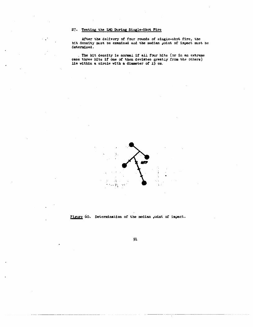
27. Testing the LIG During Single-Shot Fire
After the delivery of four rounds or single-shot fire, thehit density must be examined and the medianpoint of impact must bedetermined.
• The bit density is normal if all four hits (or in an extremeease three hits if one of them deviates greatly from the others)lie within a circle with a diameter of 15 cm.
FiEure 60. Determinationof the median point of impact.
91

If the hit density does not meet this requirement, the PGmustbe inspected, the sight setting must be examinedand the firingmust be repeated.
If after repeatedfiring the hit density is not fulfilled, thePG must be taken to the ordnancerepairshop.
If the hit density corresponds with the above-mentionedrequirements, the median point of impact must be determined.
The median point of impact is determinedas follows:
-- Connect two hits that are close to each other by a lineand halve the distance between them;
-- connect the determined point with a third hit and dividethe distance between them into three equal parts;
-- connect the division point that is closest to the firsttwo hits with the fourth hit and divide the distance betweenthem into four equal parts. The point that is closest tothe hits that were connectedfirst is the medianpoint ofimpact.
If the hits are in a symmetrical position, the median point ofimpact can be ascertained in the following manner:
-- Connect the hits next to each other in pairs, halve the twolines, connect the obtainedpoints by a line and halve it.The division point is the medianpoint of impact;
-- connect the hits crosswise by straight lines The point ofintersection of these lines is the median point of impact.
If one hit has deviated considerably from the others, it is tobe neglected and the medianpoint of impact is to be ascertainedfrom the three other hits. For this purpose, two bits have to beconnectedby a line, the center of this line is to be connected withthe third hit; the Line obtained in this manneris to be divided inthree equalparts. The point that is closest to the hits that wereconnectedfirst is the medianpoint of impact.
92

Figure 61. Determinationof the median point ofimpact at a ey~etric.1hit position.
93
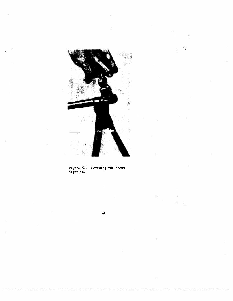
Figure 62. Screwing the front
sight in.
9i~

Figure 63. Unscrewing the screw of the front sight holder.
If the median point of impact deviates more than 5 cm fromthe check point, the position of the front sight or of the front
sight protection must be changed, i.e. if the median point of impactis too low, the front sight must be screwed in, and if the medianpoint of impact is too high it must be unscrewed. -
If the median point of impact is left (right) of the checkpoint, the front sight protection must be moved to the left (right).
95

After the position of the front sight baa been changed,thePG must be tested onesmore • The front sight protection is to beadjusted as follows:
Loosen the front sight screwWith S key (three to four turns),move the front sight protection with hk~? and punch sideways,tighten the screw and screw down the nut.
- It is prohibited to unscrewthe front sight screw withoutloosening the nut. The threadingor unscrewingof the front sightby one turn (1 me) or the lateral movement of the front sight pro-tection by 1 mm changesthe position of the point of impact duringfiring at a distance of 100 m by Li cm.
The amount of front sight adjustmentis determined by mk~ltip1yingthe deviation of the medianpoint of impact from the check pointwith the correction coefficient.
The correction coefficient for the PG at the given requirements,distance 100 m, sight 3, length of the line of sighting 595.5 ian,amounts to 0.0595. (The correction coefficient permits deviationsof 1cm).
Example:
a) The medianpoint of impact has deviated from the checkpoint 16 cm toward the right and 8 cm upward. The front
- sight protection is to be moved by 0.0595~l6S 0.952 me1 mm to the right, and the front sight is to be unscrewed
by 0.05958 * 0.~76 ~ 0.5 me.
b) The medianpoint of impact has deviated from the checkpoint 25 cm toward the left and 20 cm downward• The frontsight protection is to be moved by O.0595~’25 l.~e875me: j~5 to the left, and the front sight must be screwedin by 0.059520 * 1.19 me 1.2 me.
Remark: The deviation of the median point of impact ismultiplied with the correction coefficient, and the result isobtained in i.
96

28. Testing of the hG During Automatic- Fire
After the delivery of eight rounds in three or four bursts, thehit density must be examined and the medianpoint of impact determined.The bit density of the PG is normal if not less than 6 bits are Withina circle having a diameter of 20 cm. -
After automatic fire, the median point of impact is to be
determined as follows:
- -- The hits with the greatest deviation are neglected;
-- above or below half of the remaining hits are to becounted and divided by a horizontal line;
-- in the same manner, half of the hits are to be countedand divided from each other by a vertical line; -
The point of intersection of the vertical and horizontalline is the median ,~ointof impact.
-i -
- -~--~~.
MTP • •
Figure 6~. Determinationof the Median Point of ImpactDuring Automatic Fire.
97

Shortcomings of the Weapon Which Influence the Accuracy ofFire and Their Elimination
a) The front sight is bent; the bullets deviate to the sideopposite the misalignment of the front side tip.
If the medianpoint of impact during automatic firedeviates more than 5 cm from the cheek point, the frontsight must be adjusted.
Elimination: Unscrew the front sight, straighten itand screw it in again. If the front sight cannot bestraightened it must be exchahged. After this repair, thePG must be tested.
b) The rear-sight leaf is bent. The bullets are deviatingtoward the misalignmentof the sight notch recess
Elimination: In case of insignificant miBaligament ofthe sight notch recess, move the front sight protectionin the direction of the misalignmentof the sight notchrecess. Then test the PG.
c) The zero-notch of the scale has shifted toward the sightnotch. The bullets deviate in the direction of the sightnotch misalignment.
Elimination: The sight notch must be placed on the zero-notch of the scale by turning the adjusting screw. Then testthe PG. Should an independentmisalignmentof the sight
notch take place during firing, the front sight cam oradjusting screw must be replaced.
d) - The front sight protection has shifted laterally. -
The bullets deviate in the direction opposite to the mis-alignment of the front sight protection.
Elimination: P.&Just the front sight protection inaccordancewith the notch on the front sight holderand fasten it with the screw. Then teat the PG.
98

IX. CLEANIPG AND UJBRICATIPGTHE UG
29. The hG Must Be Cleaned and lubricated
-- after tactical training, firing practice, drill or afterprolonged exercises on the terrain daily;
-- after firing immediately after firing practice(clean it on the firing rangeand lubricateit -- complete cleaning at the barracks).During the next 3 or !~ days, the barrel -
is to be cleaned and oiled daily.
-- when not constantlyin use at least once a week.
The PG is to be cleaned and oiled by the machinegunner under
supervision of the squad leader.
The a quad leader is obligated:
-- to determinewhen and to what extent the PG must be dis-
assembled, cleaned and lubricated;
-- to check the accessories and cleaning materials as totheir condition;
-- to check the cleanliness of the PG parts and, after theparts arc clean, give the permission for the oiling andassembling of the PG.
The platoon leaders and companycommandersmust periodically
inspect the cleaning of the weapons. -
30. For cleaning and Oiling are to be Used:
a) Soapywater or sodasolution -
(for the elimination of the powder slime and for the cleaningof the parts that are exposedto the effect of the powdergases);
b) lubricating oil(for the oiling of all metal parts of the PG after cleaning);
c) clean soft rags and cotton wicks(for the cleaning and oiling of the PG);
99
I.

d) circular brushesand clean paint brushes(for the cleaningand oiling of the barrel, cartridgechamber, regulator and gas cylinder).
Other cleaning materials, oils arid fats must not be used, forthey may cause damageto the weapon. Recesses and borings can becleaned with wooden spatulas.
31. Sequenceof cleaning and lubrication
The PG is to be cleaned as follows:
-- Unscrew the muzzle screw;
- - insert the cleaning rod in the opening of the muzzle attachment,screw on the cleaningattachment and set the punch in theboring of the headat the cleaning rod;
-- fold the cleaning wick like a figure 8, set up the pointof intersection of the eight on the front side of thecleaning attachment arid wind the loops of the wick aroundthe cleaning attachment;
-- moisten the wick with soap or soda solution, shove thecleaning rod with the cleaning attachment and the wick intothe barrel and screwthe muzzle attachment onto the barrel.
Move the cleaning rod evenly sevento ten times forward andbackward through the barrel, replace the wick, saturate it With asoap or soda solution and continue the cleaning, remove the soaporsodasolution from the cleaning rod, draw clean and dry cleaning ragsthrough the barrel and the cartridge chamber; screw the oil brushonto the cleaning rod and oil the barrel and cartridge chamber.
Draw a cleaning rag, wound around a spatula and moistened ina soapor soda solution, through the regulator and the gas chamber.
Note: During the elimination of the powder slime from the gasconduit, the cleaning rod must be placed into the barrel.
The casing must be cleaned with a dry cleaningrag and then oiled.The gas cylinder must be washed with a soapor soda solution and thendried and lubricated.
100

All other parts of the PG must be cleanedwith a dry cleaningrag and oiled. W od~nparts (butt and hand guard) must not beoiled.
At drills, during marches, in battle and at- high temperaturesand in sandy terrain, the M~sand cartridges must be especiallyprotected from dust.
After prolonged firing in dusty air, the belt-feed, the boltmechanism and the casing must be periodically cleaned and oiled.
- - For that purpose,the PG is not disassembled; c~lythe casingcover-plate is openedand the bolt is cocked. - -
If firing takes place during high temperatures,the PG’s andespecially the cartridges, must be protected againsta prolongedand direct effect of the sun, for an intense heating of the metal,especially of the cartridges, can cause stoppages.
101

Figure 65. Inserting the Mizzle Attachment on the Cleaning Rod.
Figure 66. Mounting the Wick on the Cleaning Attachment
I.
102

- ~ ~-.--~- ~ ~
Figure 67. Cleaning the barrel.

X. STORA~ OF THE UG
The I2~must always be ready for action. The machinegunners,thesquad leaders and the officers into whose care the weaponswere givenare responsible for the storageand the condition of the 14G’s, thespare parts and the accessories. During the billeting of the units Inbarracksand elsewhere, the MG’s of the units have to be stored in anarmory. The MG’ s must be placed vertically in speciaily-srraxzgedarms -
stands. The biped is to be folded and securedby means of the springlock. The bolt mechanismis to be uncockedandthe sight slide is tobe placed on front sight 1.
The belts are to be stored in the drums In the lowest compartmentof the standor in cabinets. The accessories~st be in the recessofthe butt.
During the billeting of a unit In emergencyquarters (sulasercamp,village) the MG’ a have to be stored. in an appropriate dry place (notnear doors, stovesor heating apparatuses). They haveto be placedon benches, storedon shelvesor hung on nails or hooks.
During railrond. transports, the MG’ s have to be placed in standsprovided for this purpose or stored on shelves in such a way thatthey cannot fall out and be damaged.
During short railroad transportsor transport on motor vehicles,the PG’s must be held by the machinegunnersbetweenthe knees. TheP41’s are to be protected against blows, dust effect, dirt, precipitationor action by the sun.
SparePG’s are generally stored at the armory. The equi~mmntofthe storage place must be in accordancewith the regulations concerningthe storage of artillery aru~nt arid aasiunition.
In exceptional canes, when no equippedstoragerooms are available,the weapons can be stored in boxeswith special permission.
In the armory, the PG’s are to be placed in stands. The drumswith the belt are to be stored on racks, the accessorieshaveto bein the butt of the P41, eM the spare parts have to be stored in cabixmtsor on racks.
The standshave to be supplied with ord1n~Jn.unbersandwith achart showingthe unit to which the arms belong andthe serial numbersof the arms.
The comm~nMng officer to whom the MG’s were delivered is responsiblefor their condition in the armory. -
lO~

He is obligated:
-- to examinethe technical condition of the 14G’ a in the storageplace periodically; -
-- to be exactly informed after inspection about the accuracyof fire of the MG’s;
-- if necessary,to have the PG’s cleanedand inspected after adiscussion with the head of the armory.
105

c. A1’2~!uNrrIaN -
32. General
- The UG fires 7.62 mrs short cartridges, Model 1943. In accordancewith their operational possibility, the cartridgesare of -~ariableconstruction.
The weight of the bullets and the initial elocity enable the firingwith all types of cartridges at the same sighting position.
Both live anddrill cartridgesare used.
33. Live cartridges
Live cartridges are divided into cartridges with or~~inarybulletsand cartridges with special bullets.
Cartridges with ordinary bullets are used for combatagainstliving targets of the ad~ersary.
Cartridgeswith special bullets are used according to theiiconstruction for target indication, fire correction, for the ignitionof fuel and inflammable substances, as well as for combat againstlightly-armored targets.
Cartridges with tracer bullets are used for target indication,fire correction and combat against living targets. They are able toignite easily combustible objects.
The bullet leaves behind in flight a red luminous track that is
easily visible by day and night.
The tracer composition burns for a flight distance of SOOn.
Cartridgeswith incendiary armor bullets are used for the ignitionof engi.ne fuels arid fuels and for combatag8~insttargets behind slightlyarmored shelters at a distance of up to 300 ni.
Cartridges with in~ndiary bullets are used for the ignition ofengine fuel and fuels in metal containers or tank cars with a wallof thickness of up to 3 rtrn, arid for the ignition of easily inflazrmiableobjects at a distance of up to 700 m.
The bullet leavesa red luminous track behindthat is easilyvisible by day and night.
106

The tracer composition burns for a flying range of 700 a.
Construction of the live cartridges
The live cartridge (figure 68) consistsof cartridge case 1,bullet 2, powder charge 3 and percussioncap ~.
The cartridge case consists of the cartridge case jacket 1 a,in which the powdercharge is contained, the neck of the cartridge 1b, into which the bullet is pressed;the baseof the cartridge case1 c, in which the percussioncap is inserted.
-In the baseof the cartridge case is the percussioncap and theanvil 1 d, on which the percussioücap is smashed by the point of thefiring pin, two detonatingcanals1 e, through which the explosive flameof the percussion cap reaches the powder chargearid ignites it.
The percussion cap consists of a brasscap with pressedin detonatorcompositionend a foil that is shieliiing the detonatorcomposition.
107

0 3
id
-- 13
Ptgure 68. LIve cartr1d~e, 1 — Cartridgeoane; is - cartridge bodyi lb — neck ot cartridgei 10 — cartridgecue base; id — anvil; le — detonat~gcanals; 2 — bullet; y — powder charge; ~4— percuuion cap.

p~gwe 69. Bulletsi 1 — Ordthax’ybullet; 1* — Jacket; lb — lead casing; lo — cor; 2 — tracer bullet;2a — Jacket; 2b — lead core; 2o — charge; 24 - traoez’ coaposition; 2e — detonatoroo~oaition;2f — exhaust; 3 — armor incendiarybuuet; 3a — Jacket; 3b — nose of bullet; 3c — lead cuing;3d — core; 3e — charge; 31’ — detonator composition; l3 — incendiarybullet; 4s — Jacket; 4b —
nose of bullet; 4c — lead casing; ~d — core; 1e — charge; ~4t— tracer composition; hg — deto-nator composition; 4h — powder train.

34. Identification characteristics of the bullets.
The nose of the ordinary bullet is uncovered.
Weight:7.9 g
The nose of the tracer bullet is green.
Weight: 7.5 g
The nose of the armor incendiary bullet is black arid has ared ring.
Weight: 7.7 &
The nose ot’ the incendiary bullet is red.
~1eight: 6.6 g
35. Hode of operation of the special bullets
Tracer bullet
On discharge, the detonator composition is ignited by thepowder gases. After the bullet has left the barrel, thedetonator composition ignites the tracer composition, whichduring the flight forms the tracer bullet trajectory.
Armor Incendiarybullet
The steel core penetrates the armor on the impact of thebullet. The incendiary agent is ignited during the impactof the bullet arid ignites adjacent-easily inflarrimable substances.
Incendiary bullet -
On discharge, the detonator composition is ignited by the
powdergases.
After the bullet has.left the barrel, the detonator compositionignites the tracer composition, which during the flight formsthe tracer bullet trajectory. -
The incendiary agent is ignited during the impact of the bulletand explodes the nose provided with tonbacand the jacket ofthe bullet. The flame resulting from it ignites all easilyinflaniiable substances. If the tracer composition has not yetbeen cor~plet.elyburnt, it also causes the ignition of alleasily infLammable substances.
no

36. Practice cartridges -
Practice cartridges include dummy and blank cartridges, 7.62 mm,model 1943. -
The dummy cartridge is intended for training. It has a longitudinalrecess on the cartridge-case jacket and deep indentations at the neck
of the cartridge. The percussioncap is deactivated. There is nopowder charge in the cartridge case.
- The blank cartridge is provided for fire imitation during tacticalexercises. It has no bullet. The neck of the cartridge is radiallypressedtogether.
3~!• Packing of the cartridges
The cartridges are furnished in iron-mounted wooden boxes. Ineach box are two zinc cases. The box has the following inscriptions:
- Caliber of the cartridge, model of the bullet arid metal of
the cartridge case;
- numberof the cartridges in the box;
- number of the shipment and of the manufacturingfirm;
- month and year of manufacture;
- brand of’ the powder.
If the cartridges are contained in packages(cardboardboxes of20 each), the inscription “In Packages” is added.
The box cover must also indicate the nomenclatures,the classofthe shipment, a danger signal and the total weight of the box.
Numeralsare stavedin on the bottom of cartridge cases. The• upper figure is the number of the manufacturing firm, arid the lower
one that of the manufacturingyear.
The cartridges are packed in galvanizedcasesof 660 eachwithout
packages,or of’ 460 each in packages.
33. Safekeepingand storing of the ammunition
The ammunition must be-protectedagainst moisture, dust andhumidity. Damp ammunitioncan rust in a few days arid become unusable
for firing.
113.


