service manualfrankshospitalworkshop.com/equipment/documents/automated_analyzer...service manual 8...
TRANSCRIPT

A15
SERVICE MANUALENGLISH


TESE00005-11-INGJuly - 2009
SERVICE MANUALEnglish


TABLE OF CONTENTS1. INTRODUCTION ................................................................................ 8
1.1. GENERAL DESCRIPTION OF THE ANALYZER ..............................................................81.1.1. Operating arm ........................................................................................................................................ 91.1.2. Dispensing system................................................................................................................................ 91.1.3. Reactions rotor and reading .............................................................................................................. 101.1.4. Electronic system................................................................................................................................ 111.1.5. Application program ........................................................................................................................... 11
1.2. FUNCTIONING OF THE ANALYSER ..............................................................................111.3. TRANSPORT AND RESHIPMENT OF THE ANALYZER ...............................................12
2. MECHANICAL ELEMENTS ............................................................. 142.1. Instrument breakdown ...................................................................................................142.2. Description of the mechanical elements .....................................................................14
2.2.1. Operating arm ...................................................................................................................................... 142.2.1.1. X Guide. ........................................................................................................................................ 152.2.1.2. X Carriage .................................................................................................................................... 162.2.1.3. Y Carriage .................................................................................................................................... 162.2.1.4. Needle unit .................................................................................................................................. 18
2.2.2. Dispensing system.............................................................................................................................. 192.2.2.1. Thermostated probe ................................................................................................................... 192.2.2.2. Dispensing pump ........................................................................................................................ 192.2.2.3. Tubes and containers ................................................................................................................. 212.2.2.4. Container level control sensors. ............................................................................................... 222.2.2.5. Racks tray with integrated washing station. ............................................................................ 232.2.2.6. Washing pumps ........................................................................................................................... 23
2.2.3. Reaction rotor with integrated optical system. ................................................................................ 242.2.3.1. Thermostated rotor and photometric system .......................................................................... 242.2.3.2. Lighting system ........................................................................................................................... 26
2.2.4. Electronics cover ............................................................................................................................... 272.2.5. Main cover hinges ............................................................................................................................... 282.2.6. Base ...................................................................................................................................................... 292.2.7. Casings ............................................................................................................................................... 30
3. Electronic system ........................................................................... 313.1 CPU Board (CIIM00026) ..................................................................................................313.2 Power Supply Board (CIIM00015) ..................................................................................363.3 Needle Board (CIIM00017) ..............................................................................................383.4 Photometry Board (CIIM00027) ......................................................................................403.5 XYZ Interconnection Board (CIIM00018) .......................................................................413.6 Communications Board (CIIM00036) ............................................................................423.7 Rotor interconnection board (CIIM00029) .....................................................................433.9 Pump interconnection board (CIIM00028) ....................................................................453.10 Component relation .....................................................................................................473.11 Auxiliar channel information ........................................................................................473.12 Interconnection between boards .................................................................................513.13 Schematic liquid circuit ................................................................................................57
4. SERVICE PROGRAM ...................................................................... 584.1 Initialising the analyser ..................................................................................................584.2. ADJUSTMENTS .............................................................................................................60
4.2.1. Adjustment of the needle thermostatation system .......................................................................... 604.2.2. Adjustment of the rotor thermostation system ................................................................................ 614.2.3. Adjustment of the positioning of the operating arm ........................................................................ 624.2.3.1 Adjustment of X, Y and Z position for reagent and pediatric racks ............................................. 62

Service manual
4.2.4. Adjustment of the positioning of the rotor ....................................................................................... 654.2.4.1. Centering of the rotor with regard to the dispensing point ......................................................... 654.2.4.2. Centering of the rotor with regard to the optical system ............................................................. 654.2.5 . Adjustment of the positioning of the filter wheel ............................................................................ 664.2.6. Adjustment of the level control scales .............................................................................................. 674.2.7. Adjustment of the level detection sensitivity ................................................................................... 68
4.3. TESTS ..............................................................................................................................684.3.1. Motor tests ........................................................................................................................................... 684.3.1.1. Initialization test ............................................................................................................................... 694.3.1.2. Movement test .................................................................................................................................. 694.3.1.3. Loss step test ................................................................................................................................... 704.3.1.4. Stress mode test .............................................................................................................................. 704.3.1.5. Z axis secu ri ty systems test............................................................................................................ 704.3.1.6 Maximum Z verification test ............................................................................................................. 714.3.2. Diaphragm pumps and electrovalves test ........................................................................................ 714.3.2.1. Functioning test ............................................................................................................................... 724.3.2.2. Stress mode test .............................................................................................................................. 724.3.3. Needle self-centering system test ..................................................................................................... 724.3.4. Needle level detection system test .................................................................................................... 724.3.5. Needle thermostatation system test.................................................................................................. 734.3.6. Needle rotor thermostatation system test ........................................................................................ 744.3.7. Photometry tests ................................................................................................................................. 744.3.7.1. Base line and integration times ...................................................................................................... 744.3.7.2. Darkness counts .............................................................................................................................. 764.3.7.3. Repeatability without moving the filter wheel ............................................................................... 764.3.7.4. Stability ............................................................................................................................................. 774.3.7.5. Repeatability moving filter wheel ................................................................................................... 774.3.7.6. Absorbance measurement .............................................................................................................. 784.3.7.7. Reactions rotor check...................................................................................................................... 784.3.8. Level control scales test..................................................................................................................... 794.3.9. Covers detection test .......................................................................................................................... 794.3.10. PC-Analyzer communications channel test.................................................................................... 804.3.11. Global stress mode of the analyzer ................................................................................................. 804.3.12. Photometry tool ................................................................................................................................. 81
4.4. UTILITIES .......................................................................................................................824.4.1. Disassembly of the dispensing needle ............................................................................................. 824.4.2. Fluid system supply ............................................................................................................................ 834.4.3. Cleaning of the dispensing system ................................................................................................... 844.4.4. Changing the lamp .............................................................................................................................. 844.4.5. Configuration of the filter wheel ........................................................................................................ 854.4.6. Demonstration mode .......................................................................................................................... 854.4.7 Read/load adjustments and cycles..................................................................................................... 864.4.8 Change the rotor type .......................................................................................................................... 87
4.5. REGISTER .......................................................................................................................884.5.1. Introducing the analyzer serial number ............................................................................................ 884.5.2. Service Reports ................................................................................................................................... 894.5.3. Language change ................................................................................................................................ 894.5.4. Users .................................................................................................................................................... 90
4.6. MONITOR .......................................................................................................................904.7 User’s program ...............................................................................................................91
4.7.1 Configuration of the level of access to the analyser ....................................................................... 914.7.2 Reagent Consumption ........................................................................................................................ 92
5. MAINTENANCE AND CLEANING .................................................. 945.1. MAINTENANCE OPERATIONS ......................................................................................94
5.1.1. Housings and covers .......................................................................................................................... 945.1.1.1. Removing the needle unit casing .............................................................................................. 945.1.1.2. Removing the front housing ...................................................................................................... 945.1.1.3. Removing the main cover .......................................................................................................... 95

5.1.1.4. Removing the upper casing ....................................................................................................... 965.1.1.5. Removing the spring protector .................................................................................................. 98
5.1.2. Operating arm ...................................................................................................................................... 985.1.2.1. Fully removing the operating arm ............................................................................................. 985.1.2.2. Changing the arm hose ............................................................................................................. 995.1.2.3. Changing the X motor ............................................................................................................... 1005.1.2.4. Changing the Y motor ............................................................................................................... 1025.1.2.5. Changing the Z motor ............................................................................................................... 1025.1.2.6. Changing the Y motor belt ....................................................................................................... 1035.1.2.7. Changing the spring ................................................................................................................. 103
5.1.3. Dispensing system............................................................................................................................ 1045.1.3.1. Changing the thermostated pipe. ........................................................................................... 1045.1.3.2. Changing the dispensing pump seal ...................................................................................... 1055.1.3.3. Changing the dispensing pump motor ................................................................................... 1065.1.3.4. Changing the dispensing electrovalve ................................................................................... 1075.1.3.5. Changing the container tube unit ............................................................................................ 1075.1.3.6. Changing the distilled water container filters ........................................................................ 107
5.1.4. Reactions rotor and reading ............................................................................................................ 1085.1.4.1. Changing the rotor temperature probe ................................................................................... 1085.1.4.2. Fully removing the rotor ........................................................................................................... 1095.1.4.3. Changing the rotor Peltier cells ............................................................................................... 1095.1.4.4. Changing the rotor cover detector .......................................................................................... 1105.1.4.5. Changing the rotor start photosensor .................................................................................... 1105.1.4.6. Changing the rotor motor ..........................................................................................................1115.1.4.8. Changing the lamp .................................................................................................................... 1125.1.4.9. Changing an optical filter ......................................................................................................... 1135.1.4.10. Configuration of the filter wheel ............................................................................................ 1135.1.4.11. Changing the filter wheel start photosensor ........................................................................ 1135.1.4.12. Changing the filter wheel motor ............................................................................................ 114
5.1.5. Electronic Systems ........................................................................................................................... 1145.1.5.1. Changing the X, Y and encoder start photosensor ................................................................ 1145.1.5.2. Changing the microprocessor board ...................................................................................... 1155.1.5.3. Changing the power supply board .......................................................................................... 1155.1.5.4. Changing the main power supply source ............................................................................... 1165.1.5.5. Changing the photometric system board ............................................................................... 1165.1.5.6. Changing the front indicator .................................................................................................... 1175.1.5.7. Changing the firmware program .............................................................................................. 118
5.2. RECOMMENDED PREVENTIVE MAINTENANCE .......................................................1185.3. CARE AND CLEANING .................................................................................................119
5.3.1. General care of the analyzer ............................................................................................................ 1195.3.2. Cleaning the optical system ............................................................................................................. 1195.3.3. Cleaning the dispensing system ..................................................................................................... 1205.3.4. General cleaning of the interior of the apparatus .......................................................................... 120
A I. TECHNICAL SPECIFICATIONS ................................................. 121A II. ADJUSTMENT MARGINS TABLES .......................................... 125A III. LIST OF CONSUMABLES, ACCESSORIES AND SPARES ... 126A IV. LIST OF REQUIRED TOOLS .................................................... 128A V. SOFTWARE VERSIONS ............................................................ 128

Service manual
8
1. INTRODUCTIONThe A15 analyzer is an automatic random access analyser specially designed for performing biochemical and turbi-dimetric clinical analyses. The instrument is controlled on-line in real time from an external dedicated PC.
In each of the elements of the A15 analyser, BioSystems has used leading edge tech nology to obtain optimum ana-lytical performance, as well as taking into account eco no my, robustness, easy use and maintenance. A three-axis Cartesian operating arm prepares the reactions. Dispensing is performed by means of a pump with a ceramic piston via a detachable thermostated needle. A washing station guarantees that the needle is kept perfectly clean through-out the process. The reactions take place in a thermostated rotor in which absorbance readings are taken directly by means of an integrated optical system.
This manual contains the information required for learning about, maintaining and repairing the A15 automatic ana-lyzer. It should be used by the Technical Service as a learning and consultation docu ment for the maintenance and repair of the instru ment. Chapter 2 describes the different mechanical elements that form the analyzer together with their functionality, and chapter 3 describes the electronic system. Chapter 4 describes the Service Program. All the adjustments and checks of the analy zer are carried out through this program, which is independent from the appli cation program (User Program). The separation of both programs enable it to be maintai ned separately and the extensions and improvements of one do not affect the other. The user does not have the service program. The Technical Service must install it on the user’s computer in order to carry out the service requirements. Once said tasks have been car-ried out, the Technical Service must uninstall the program. Chapter 5 offers instructions for the different mainte nance, rep air and cleaning operations that can be carried out by the Technical Service. The annexes contain a summary of the technical specifications of the analyzer, the adjustment margin tables, the lists of accessories and spares, a list of software versions and their compatibility and a software troubleshooting guide.
1.1. GENERAL DESCRIPTION OF THE ANALYZER
The A15 analyser is made up of three basic elements: the operating arm, the dispensing system and the reading and reactions rotor. The electronic system of the instrument controls said elements and communicates with the external computer containing the application program. Through this program, the user can control all the operations of the analyzer.

9
1.1.1. Operating arm
This is a three-axis XYZ Cartesian mechanism. The X and Y axes move the dis pens ing needle over the analyser horizontally and the Z axis moves it vertically. It is operated by three step-by-step motors. In each 24-second prepara-tion cycle, the operating arm performs the following actions: first of all, it sucks in the reagent from the corresponding bottle. Next, the needle is washed externally in the washing station and sucks in the sample from the corresponding tube. It is washed externally again and dispenses the sample and the reagent into the reactions rotor. Finally, it is exhaustively washed internally and externally before proceeding with the next preparation. The arm has a system for controlling vertical movement to detect whether or not the needle has collided into anything on descending. If a collision occurs, as may be the case if, for example, a lid has been left on a bottle of reagent, the arm automatically restarts, verifies the straightness of the needle and continues working issuing the corresponding alert to the user. A vertical axis retention system prevents the needle from falling in the case of a power cut, avoiding injury from the needle to the user or the needle being bent by an attempt to move the arm manually. The operating arm only makes the preparations if the general cover of the analyser is closed. If the cover is raised while it is functioning, the arm automati cally aborts the task in progress and returns to its parked position to avoid injury to the user.
1.1.2. Dispensing system
This system consists of a thermostated needle, supported and displaced by an operating arm and conne ct ed to a dispensing pump. The needle is detachable to enable cleaning and replacement. The analyser has capacity level detection to control the level of the bottles and tubes and prevent the needle from penetrating too far into the corre-sponding liquids, thus minimising contamination. An automatic adjustment system informs the user if the needle is not mounted or if it is too bent. The needle has a sophisticated Peltier thermos tatation system, with PID control, capable of thermostating the preparations at approximately 37º in less than 15 seconds. Dispensing is carried out by means of a low maintenance ceramic piston pump driven by a step-by-step motor. It is capable of dispensing between 3 and 1250 ml. The exterior of the needle is kept cons tantly clean by a wash station included in the base. A membrane pump transports the waste to the corresponding container.
The A15 analyser has a tray with 4 free positions for racks of reag e nts or samples. Each reagents rack can carry up to 10 reagents in 20 ml or 50 ml bottles. Each samples rack can contain up to 24 tubes of samples. The samples can be patients, calibrators or controls. The analyser can be configured to work with 13 mm or 15 mm diameter tubes of samples with a length of up to 100 mm or with paediatric wells. Any possible configuration of racks can be mounted from 1 rack of reagents (10 reagents) and 3 racks of samples (72 samples) to 3 racks of reagents (30 reagents) and 1 rack of samples (24 samples).
On the left of the analyser are the waste and distilled water containers. The analyser constantly controls the level of these containers and issues the appropriate alerts if the distilled water is nearly empty or if the waste container is full.

Service manual
10
1.1.3. Reactions rotor and reading
The preparations are dispensed in an optical quality methacrylate reactions rotor thermos tated at 37ºC. The optical absorbance readings are taken directly on this rotor. Each reaction can be read for 10 minutes. The readings are taken as they are programmed in each measurement procedure. The reaction wells have been designed to enable the mixture of the sample and the reagent during the dispensing. Each rotor has 120 reaction wells. The length of the light path is 6 mm. The minimum volume required to take the optical reading is 200 uL. The wells have a maximum useful capacity of 800 uL. When the reactions rotor is completely full, the user must change it for one that is empty, clean and dry. The reactions rotors can be reused up to 5 times if they are carefully cleaned immediately after use. The Cleaning the semi-disposable reactions rotor section in the Installation and maintenance manual describes how to cle an the rotors. The us er has a test in the computer programme, which he or she may use to check the condition of the rotor. The rotor is driv en by a step-by-step motor with a transmission. A Peltier system with PID control ther-mostates the rotor at 37ºC.
An optical system integrated in the rotor takes the readings directly on the reaction wells. The light source is a 10 W halogen lamp. The detector is a silicon photodiode. The wavelength is selected by a drum with 9 positions available for optic filters. The filters are easily ch an ged by the user from the exterior of the analyser, without the need for disas-sembling the filter drum. A step-by-step motor positions the drum. The optical system is capable of taking 1.25 readings per second, with or without a filter change in between. The light beam from the lamp passes through a compensated interferential filter to select the desired wavelength. It then passes through the rotor well and finally reaches the pho-todiode, where the light signal is turned into an electric signal. A sophisticated analogical digital integrator-converter system converts the electric signal into a digital value with which the analyser obtains the absorbance values. The optical system continues to work when the general cover of the ana lyser is open, whereby the analyser can continue to take readings while the user handles, for example, the sample tubes or the reagent bottles. The rotor cover must be in place for the optical system to work correctly.

11
A detector tells the analyser of the presence of the cover. The analyser aborts the readi ngs if the user removes the rotor cover while the optical system is taking photometric measurements. If the rotor is not covered, the analyser informs the user so that he or she places the rotor cover when it sends samples to be analyzed.
1.1.4. Electronic system
The described elements are controlled by an electronic system based on a micropro cessor. The microprocessor has two exter nal communication channels to connect the instrument to the computer containing the application pro gram. The electronic system is made up of the following independent boards:
- Microprocessor board- Photometric system board- Needle conditioning board- Fluid system interconnection board- Arm interconnection board- Rotor interconnection board- Power supply board
1.1.5. Application program
The application program makes it possible to control all the operations of the analy zer. Fro m this program, the user can monitor the state of the analyzer and the work session, program parameters, e.g. technique parameters, prepare the work session, prepare results reports, configure different analyzer options, activate various test utilities, prepare and maintain the instrument and carry out internal quality control processes. The purpose of this manual is not to explain the fun ction ing of the user program. For detailed information to this re gard, please con sult the User Manual included with the analyzer.
1.2. FUNCTIONING OF THE ANALYSERThe A15 analyser is an automatic random access analyser specially designed for performing biochemical and turbi-dimetric clinical analyses. The analyser performs patient-by-patient analyses and enables the continual introduction of samples. The analyser is controlled from a dedicated PC that is permanently com muni cated to the instrument. The programme, installed on the computer, keeps the user constantly informed of the status of the analyser and the progress of the analyses. As results are obtained, the com pu ter shows them to the user immediately. When a Work Session is begun, the ana ly ser proposes performing the blanks, calibra tors and controls programmed

Service manual
12
for the measurement procedures it is to carry out. The user may choose between performing the blanks and the calibra tors or not. If they are not performed, the analyser uses the last available memorised data. The controls can also be activated or not. During a session, while the analyser is working, the user can introduce new normal or urgent samples to be analyzed. Each time a new sample is added, the analyser automa tical ly proposes the possible new blanks, calibrators or controls to be performed. A work session can remain open for one or more days. When a session is closed and another new session is opened (Reset Session), the analyser again proposes performing the blanks, calibrators and controls. It is recommended that the session is reset each working day.
The analyser determines the concentrations of the analytes based on optical absorbance measurements. To measure the concentration of a certain analyte in a sample, the analyser uses a pipette to take a specific volume of the sample and the corresponding reagent, quickly thermostates them in the needle itself and dispenses them into the reactions rotor. The very dispensing speed together with the geometry of the reaction well causes the mixture to be shaken and the chemical reaction begins. In the bireagent modes, the reaction begins when the analyser later dispenses a second reagent in the same reaction well. The reactions can be biochemical or turbidimetric. In both cases, the reaction or the chain of reactions produced generate substances that attenuate certain wave len gths, either by absorption or by dispersion. Comparing the light in ten sity of a certain wavelength that crosses a well when there is a reaction and when there is not a reaction can determine the concentration of the corresponding analyte. This comparison is quantified with the physical magnitude called absorbance. In some cases, the concentration is a direct function of the absorb-ance, and in other cases, it is a function of the variation of the absorbance over time, depending on the analysis mode.
1.3. TRANSPORT AND RESHIPMENT OF THE ANALYZER
If the analyser is to be reshipped or moved using a transport vehicle, it is important to block the operating arm and use the original packaging to ensure that the apparatus is not damaged. To package the instrument, we recommend you follow the following instructions: (on the unpackaging instruc tions sheet)
13

Service manual
14
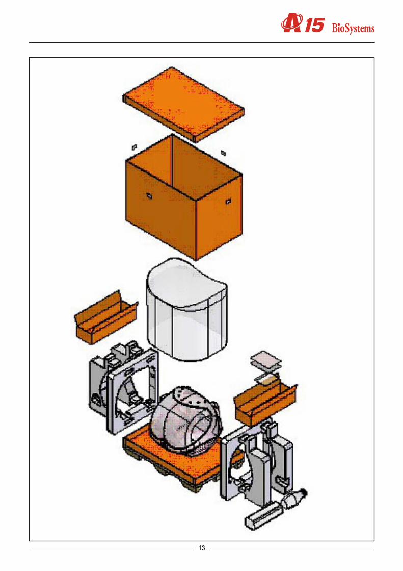
2. MECHANICAL ELEMENTS2.1. Instrument breakdown
The physical structure of the analyzer can be broken down as follows:
-Operating arm -X guide -Y guide -X carriage -Y carriage -Needle unit-Dispensing system -Thermostated probe -Dispensing pump -Tubes and containers -Container level control sensors -Racks tray with integrated washing station -Waste pump-Reactions rotor with integrated optical system -Thermostated rotor and photometric system. This contains the electronic photo metric system board -Lighting system-Electronics box.This houses the electronic boards of the microprocessor, the power sup ply and the front indicator-Main cover hinges-Base-Housings -Upper casing -Front housing -Arm casing -Main cover
The following is a brief description of each of the mechanical elements that make up the analyzer.
2.2. Description of the mechanical elements2.2.1. Operating arm
This mechanism positions the dis pen sing needle appropriately during the prepara tion of the analyses. An encoder checks the vertical movement of the needle and a spring automatically stops it from falling in the case of a power cut. The dispen sing pipe and the electrical hoses of the arm pass through the front casing
(1) X GUIDE(2) X CARRIAGE(3) Y CARRIAGE(4) Y GUIDE(5) NEEDLE UNIT(6) CONTROL AND DISPENSING PIPE HOSE
The needle unit (5) supports the thermostated needle and can move on the Y carriage (3), which can move on the Y axes (4). The Y axes are supported by the X carriage, which moves on the X axes (1). In this way, the needle can be moved in the three Cartesian directions of X, Y and Z. The hose (6) houses the Teflon dispensing tube and all the electrical ho se s of the arm.
15
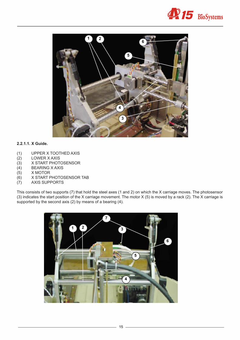
2.2.1.1. X Guide.
(1) UPPER X TOOTHED AXIS (2) LOWER X AXIS(3) X START PHOTOSENSOR(4) BEARING X AXIS(5) X MOTOR(6) X START PHOTOSENSOR TAB(7) AXIS SUPPORTS
This consists of two supports (7) that hold the steel axes (1 and 2) on which the X carriage moves. The photosensor (3) indicates the start position of the X carriage movement. The motor X (5) is moved by a rack (2). The X carriage is supported by the second axis (2) by means of a bearing (4).
1 3
6
4
5
2
7
1 2
3
4
5
6
Service manual
16
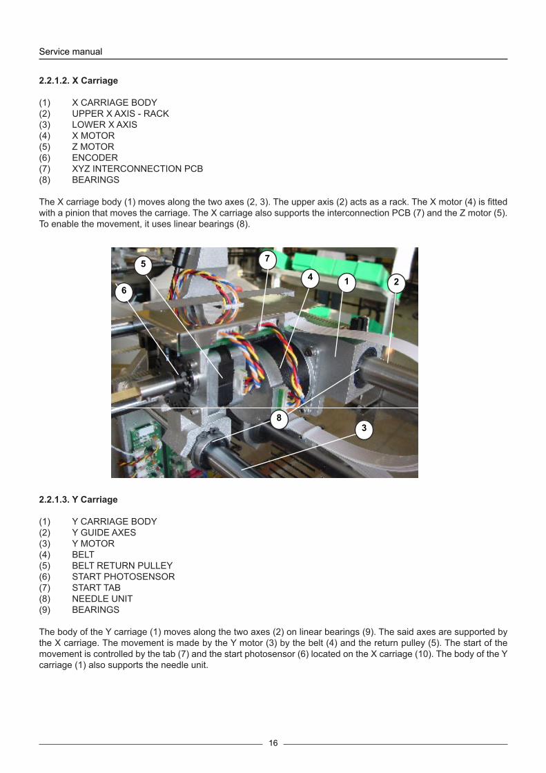
2.2.1.2. X Carriage
(1) X CARRIAGE BODY(2) UPPER X AXIS - RACK(3) LOWER X AXIS (4) X MOTOR(5) Z MOTOR(6) ENCODER(7) XYZ INTERCONNECTION PCB(8) BEARINGS
The X carriage body (1) moves along the two axes (2, 3). The upper axis (2) acts as a rack. The X motor (4) is fitted with a pinion that moves the carriage. The X carriage also supports the interconnection PCB (7) and the Z motor (5). To enable the movement, it uses linear bearings (8).
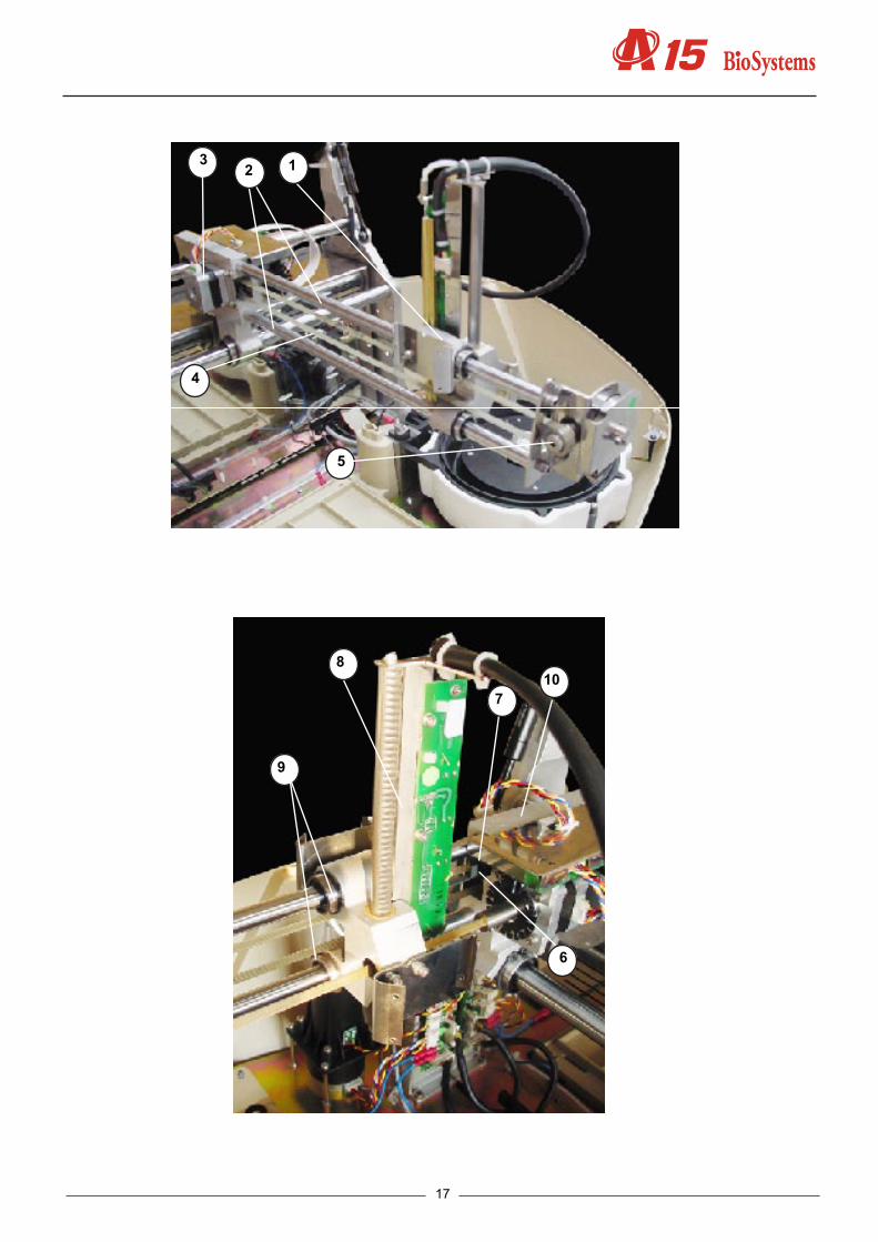
2.2.1.3. Y Carriage
(1) Y CARRIAGE BODY(2) Y GUIDE AXES(3) Y MOTOR(4) BELT(5) BELT RETURN PULLEY(6) START PHOTOSENSOR(7) START TAB(8) NEEDLE UNIT(9) BEARINGS
The body of the Y carriage (1) moves along the two axes (2) on linear bearings (9). The said axes are supported by the X carriage. The movement is made by the Y motor (3) by the belt (4) and the return pulley (5). The start of the movement is controlled by the tab (7) and the start photosensor (6) located on the X carriage (10). The body of the Y carriage (1) also supports the needle unit.
1 2
3
45
6
7
8
17
123
4
5
6
7
9
810

Service manual
18
2.2.1.4. Needle unit
(1) Z GUIDE(2) RACK(3) Z MOTOR(4) ENCODER(5) TRANSMISSION AXIS(6) RETURN SPRING(7) THERMOSTATATION PIPE(8) CONTROL PCB(9) Y CARRIAGE
The Z guide (1) supports the thermostatation pipe (7) and the control PCB (8) where the heating elements are located, together with the thermistor signal amplifier and level detection and the Z axis start photosensor. The rack (2) supports the Z guide (1) which crosses the Y carriage (9) on two bearings. The Z motor (3) is fastened to the X carriage (10) and is moved by a transmission axis (5) fitted with a pinion that acts on the rack. The return spring (6) acts on the transmission axis and prevents the needle from falling in the event of a power cut: The encoder (4), which detects any obstruction to the movement of the thermostated needle (9) is located on the same axis and on the part of the motor.
3
110
54
87
6
2
9

19
1
2
3
4
5
6
2.2.2. Dispensing system
The dispensing pump dispenses the preparations through the thermostated needle. The needle is washed internally and exter nally at the washing station. The racks tray makes it possible to position the samples to be analyzed and the required re a gents. The level of the distilled water and waste containers is controlled by the analyzer by capacity.
2.2.2.1. Thermostated probe
(1) THERMOSTATATION PIPE(2) PCB(3) TEFLON DISPENSING TUBE(4) ELECTRICAL CONTROL HOSE(5) FASTENING NUT(6) REMOVABLE NEEDLE
The thermostatation pipe (1) preheats the reagent during dispensing. It is fitted with two connectors at each end. The removable needle (6) is connected to one and the Teflon dispensing pipe (3) is connected to the other, fixed by the fastening connector (5). The PCB (2) contains the thermostatation elements, the thermistor and associated circuits. The various thermistor and element action signals (3) pass through the hose (4).
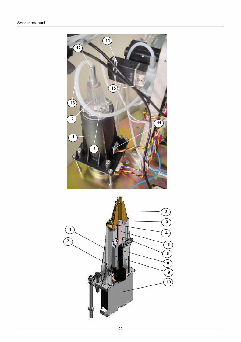
2.2.2.2. Dispensing pump
(1) BODY(2) FLUIDIC CHAMBER(3) SEAL(4) SEAL SUPPORT(5) CERAMIC PISTON(6) PISTON SUPPORT(7) START DETECTION BARRIER(8) AXIAL BEARING(9) ENDLESS SCREW(10) MOTOR(11) START PHOTOSENSOR(12) PUMP NUT(13) PUMP-ELECTROVALVE TEFLON TUBE
Service manual
20
1
2
3
4
5
6
7
9
8
10
1
2
3
11
12
13
14
15

21
(14) 3-CHANNEL ELECTROVALVE(15) ELECTROVALVE NUT
The plastic body (1) joins the different elements that make up the pump. The transparent methacrylate fluidic chamber (2) makes it possible to observe the flow of liquid through the pump. The support (4) fastens the seal (3). The ceramic piston (5) dispenses by displacing a certain volume of liquid in the chamber. The piston is adhered to the support (6), which moves alternatively by the rotation of the endless screw (9) fixed to the motor axle (10). The barrier (7), joined to the piston support, obstructs the photosensor (11) when the piston reaches its start position. The axial bearing (8) prevents any longitudinal displacement of the motor axle for greater precision in the dispensing operation. The 3-channel electrovalve (14) makes it possible to connect the pump chamber to the distilled water container or to the thermostated needle. The Teflon tube (13) connects the chamber to the electrovalve. It is connected to each of these elements by the nuts (13) and (15).
2.2.2.3. Tubes and containers
(1) WATER CONTAINER(2) WATER CONTAINER LID(3) WATER CONTAINER TUBES FASTENING(4) WATER CONTAINER TEFLON TUBE(5) TEFLON TUBE FILTER(6) ELECTROVALVE NUT(7) SYSTEM LIQUID LEVEL SENSOR CABLE(8) LEVEL SENSOR(9) WASTE CONTAINER(10) WASTE CONTAINER LID(11) FAST COUPLING NUT(12) WASTE CONTAINER PVC TUBE(13) GROMMET(14) WASTE LEVEL SENSOR CABLE
The Teflon tube (4) connects the distilled water container (1) to the electrovalve of the dispensing pump. This tube is installed at the end of the filter container (5). It is connected to the electrovalve of the dispensing pump through the nut (6) The Teflon pipe passes through the rubber piece (3) in the lid (2) of the container, which fastens them in position. The PVC tube (12) connects the waste extraction membrane pump to the waste container (9). The waste container lid (19) has a fast coupling nut (11) with automatic drip-proof closing when disconnected. All the tubes pass into the interior of the analyzer through the rubber grommet (13).
1
3
2
4
6
7
9
1011
12
13
14

Service manual
22
2.2.2.4. Container level control sensors.
(1) LEVEL DETECTION SHEETING(2) SIGNAL CONNECTOR
The analyzer has a capacitance system to control the level of the distilled water and waste containers. For this, there is an emission plane (1) under the bottles where a signal is injected through the connector (2). The base supporting the bottles is above this. They have 2 rods that collect the signal and indicate the presence or absence of liquid.
5
8
12

23
2.2.2.5. Racks tray with integrated washing station.
(1) TRAY(2) WASHING STATION(3) LEVEL DETECTION SHEETING(4) WASTE PVC PIPE
The plastic injection tray (1) is part of the base of the instrument. The washing station (2) is installed on the right. The plate (3) detects the level of the dispensing needle. The PVC tube (4) connects the washing station drain to the waste extraction pump.
2.2.2.6. Washing pumps
(1) MEMBRANE WASTE PUMP(2) WASHING STATION-PUMP PVC TUBE(3) WASTE BOTTLE-PUMP PVC TUBE(4) SAFETY FLANGES
The needle washing system has a waste extraction pump (1). This is connected to the washing station by the PVC (2). The pump expels the waste through the pipe (4) into the waste bottle. The pipes are fastened by two safety flanges.
1
2
3
4

Service manual
24
2.2.3. Reaction rotor with integrated optical system.
The reactions rotor is thermostated at 37ºC. The optical system, made up of a lighting system and a photometric system takes the readings directly on the rotor reaction wells. The lighting system has a halogen lamp, a filter drum for the selection of the wavelength form the appropriate beam of light. The photometric system contains a silicon pho-todiode and the corresponding electronics to obtain a digital value that is proportionate to the light intensity received.
2.2.3.1. Thermostated rotor and photometric system
(1) METHACRYLATE ROTOR(2) HEATING CANAL(3) THERMAL INSULATION OF THE HEATING CANAL(4) PELTIER CELLS(5) HEATSINKS(6) FANS(7) TEMPERATURE PROBE(8) ROTOR CENTRING UNIT(9) ROTOR FASTENING SCREW(10) HOME ROTOR PHOTODETECTOR(11) BEARINGS(12) PINION(13) ROTOR MOTOR (14) ROTOR CROWN(15) MOTOR SEPARATOR(16) PHOTOMETRIC SYSTEM BOARD(17) ELECTRONIC BOARD SUPPORT COVER(18) OPTICS COVER(19) PHOTODIODE GAP CENTRING UNIT(20) ROTOR GAP(21) COVER DETECTOR(22) ROTOR AXLE
1
3
4
2

25
The dispensing system dispenses the reagents and the samples in the methacrylate rotor (1). The optical system measures the absorbance directly on the rotor wells. The aluminium heating canal (2) surrounds the rotor and keeps it at 37ºC. The canal is thermally insulated from the exterior by means of the moulded expanded polystyrene insula-tion (3). The Peltier cells (4), with their respective radiators (5) and fans, act on the canal to control the temperature. The sensor used to control the temperature is the probe (7). The methacrylate rotor is fastened to its centring unit (8) by means of the screw (9). The centring unit is fixed to the heating canal through the axis (22), which is fitted on bearings (11). The barrier obstructing the photosensor (10) when the rotor reaches its start position forms part of the centring unit (8). The centring unit also acts as gearing. The pinion (12), fixed to the motor (13), acts through the crown (14), which also acts as a centring unit. The separator (15) does not allow the motor temperature to reach the heating canal. The electronic board of the photometric system (16) is housed in a cavity in the heating canal. The upper cover of this cavity (17) supports the electronic board. The seal (18) keeps the cavity hermetically closed in the case of possible liquid spillage. The housing of the filter drum is closed at the bottom by the cover (18). The part (19) centres the photodiode with regard to the lighting system and also acts as a grill to prevent the incidence of unwanted light. The grill (20) limits the light hitting the reactions rotor. The detector (21) tells the analyzer if the rotor cover is in position or not.
2
3
9
1
11
8
22
7
13
14
16
17
17
1920

Service manual
26
2.2.3.2. Lighting system
(1) BODY(2) LAMP HOLDER(3) HALOGEN LAMP(4) LAMP HOLDER FASTENING(5) FILTER WHEEL(6) FILTER HOLDER(7) FILTER HOLDER NUT(8) MATCHED INTERFERENTIAL FILTERS(9) WHEEL AXLE(10) HOME PHOTODETECTOR(11) FILTER MOTOR (12) DIAPHRAGM(13) FILTER WHEEL WINDOW COVER(14) FILTER WHEEL(15) GAP
3
6
5
4
7
10
13
15
18
21

27
The aluminium body (1) is the structure that supports all the elements of the lighting system. The lamp holder (2), fastened to the body by means of the fastening system (4), keeps the halogen lamp (3) in position without the need for adjustments. The filter drum (5) has 10 positions for optical filters. Position 0 must always be taken up by a cove-red filter. The other positions can be taken up by an interferential filter (8) or by other covered filters. No position in the drum must be left unoccupied. Each filter is fitted on a filter holder (6) and fastened to it by the nut (7). The filter holders can be dismounted from the drum by simply pulling on them. The cover (13) allows easy access to the filter drum. The filter drum is fastened to the axle (9). This axle can be turned by the direct action of the motor (11). Its end is guided by the bearing (14). The photosensor (10) indicates the start position of the drum. The light from the lamp, limited by the diaphragm (12). The light passes through the filter drum, which selects the desired wavelength, and through the aperture(15), which adapt the form of the light beam to the geometry of the rotor wells.
2.2.4. Electronics cover
(1) BACK COVER OF THE ELECTRONICS(2) MAINS SWITCH(3) FUSE HOLDER(4) ID LABEL(5) NETWORK CONNECTOR(6) COM1 CONNECTOR(7) COM2 CONNECTOR(8) HINGES
The metal cover (1) supports the mains switch (2) and the fuse holders (3), as well as the identification label (4). The COM1 and COM2 connectors (6, 7) and the mains connector (5) are fastened to the electronics box. The cover(1) opens on 2 hinges (7).
1
2
4
3
5
8
7
13
6
911
12
14
15

Service manual
28
1 2
3
45
6
7
8
2.2.5. Main cover hinges
(1) HYDRO-PNEUMATIC SPRING(2) ARTICULATED STEEL STRUCTURE(3) COVER OPEN PHOTOSENSOR (on right-hand hinge only)
The two hinges enabling the raising of the main cover of the analyzer consist of an articulated steel structure (2) operated by a hydro-pneumatic spring (1). The right-hand hinge includes a photosensor (3) to detect whether or not the cover of the analyzer is open or closed.
1
23

29
2.2.6. Base
(1) LOWER PLASTIC CASING(2) BASE(3) WASHING STATION AND RACK TRAY(4) ARM UNIT(5) ELECTRONICS BOX(6) DISPENSING PUMP(7) REACTION ROTOR AND INTEGRATED OPTICAL SYSTEM(8) BOTTLE LEVEL DETECTION PLATE(9) LEVEL DETECTION PLATE(10) PUMP AND MICROPROCESSOR INTERCONNECTION BOARD(11) MAIN COVER HINGES(12) FRONT INDICATOR(13) ADJUSTABLE LEG
The base (2) on which all the elements of the analyser are fixed is fastened directly to the lower plastic casing. The rack tray and washing station form part of the base. The instrument stands on 4 rubber legs . The front right leg (13) is adjustable in height to adapt the instrument to the work surface.
13
1
2
3
4
67
8
9
10 11
1312
5

Service manual
30
2
3
4
57
4
6
2.2.7. Casings
(1) FRONT CASING(2) UPPER CASING(3) MAIN COVER(4) LOWER CASING(5) ARM HOUSING(6) ROTOR COVER(7) RETURN SPRING COVER
The front casing (1) is fastened to the upper casing (2) and the upper casing is fastened to the lower casing (4). The top cover (3) is transparent and lets users see the analyser in operation with the cover closed.

31
3. ELECTRONIC SYSTEM1. Description of the electronics of the A15 analyzer.2. CPU Board (CIIM00026)3. Power supply board and source (SP150 & CIIM00015)4. Needle Board (CIIM00017)5. Photometry Board (CIIM00027)6. XYZ carriage interconnection board (CIIM00018)7. Rotor interconnection board (CIIM00029)8. Fluid interconnection board (CIIM00028)9. Communications Board (CIIM00036)10. Components relation11. Information about auxiliar connector12. Interconnection between boards13. Schematic liquid circuit
Description of the electronics of the A15 analyzer.
The electronics of the analyzer are made up of different boards located at different points in the analyzer and dedica-ted to specific functions. Its different location corresponds to functionality and performance criteria for the functioning of the analyzer.
There are 8 different boards, which correspond to:
CPU Board (CIIM00026)Power supply board and source (SP150 & CIIM00015)Needle Board (CIIM00017)Photometry Board (CIIM00027)XYZ carriage interconnection board (CIIM00018)Rotor interconnection board (CIIM00029)Fluid interconnection board (CIIM00028)Communications Board (CIIM00036)
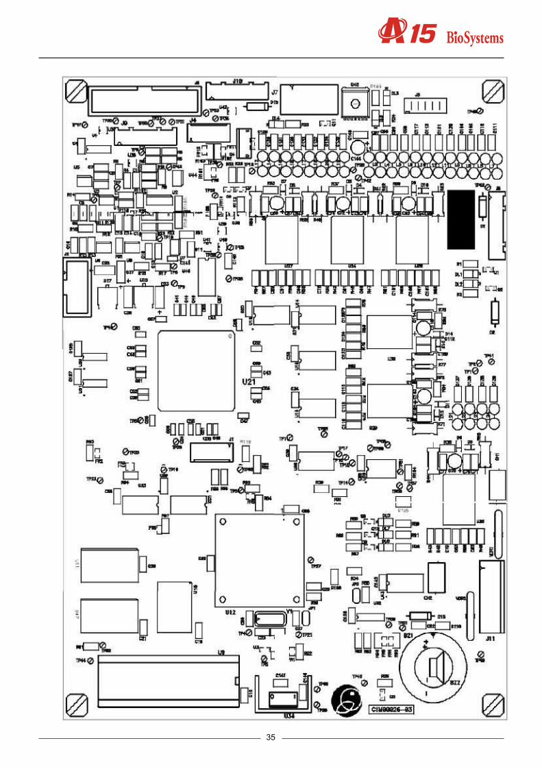
3.1 CPU Board (CIIM00026)
This is the brain of the machine, containing the microprocessor (H8/3003), responsible for controlling all the elements of the machine. The board has different data storage systems using either static RAM (U1 and U47), FLASH memory (U10) or EPROM (U9). The slot associated with the EPROM is used to check the functionality of the board and the recording of the MONITOR program in the production phases of the analyzer. The other two memories are associated with the normal functioning of the analyzer. The FLASH memory holds the application itself as well as different data-bases related to factory settings, adjustments, state of the rotor and possible extensions to the application.
The U21 device also exists on the board. This is a logical programmable device (FPGA) dedicated to the control of motors, mapped in register memory associated with end-of-run control, electrovalves, level sensing and control of the photometry-associated board (CIIM00027).
The motor control acts directly on the drivers corresponding to each of the analyzer’s axes (U28,U29,U30,U24,U25,U27) to act on the motor. The driver comprises the L6228 integrated circuit. The regulation of the current of each axis can be configured by means of a DAC that sets the current set point independently (U26).
The action on the thermostatation systems of the rotor is carried out through H-shaped bridges based on MOS te-chnology (U45) and controlled directly from the microprocessor. The action on the needle thermostatation system is through the Q4 transistor.
Service manual
32
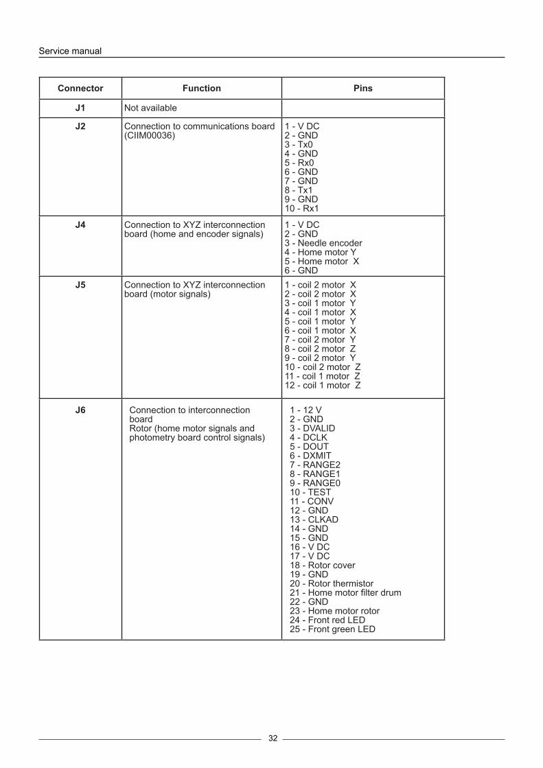
Connector Function Pins
J1 Not available
J2 Connection to communications board (CIIM00036)
1 - V DC2 - GND3 - Tx04 - GND5 - Rx06 - GND7 - GND8 - Tx19 - GND10 - Rx1
J4 Connection to XYZ interconnection board (home and encoder signals)
1 - V DC2 - GND3 - Needle encoder 4 - Home motor Y5 - Home motor X6 - GND
J5 Connection to XYZ interconnection board (motor signals)
1 - coil 2 motor X2 - coil 2 motor X3 - coil 1 motor Y4 - coil 1 motor X5 - coil 1 motor Y6 - coil 1 motor X7 - coil 2 motor Y8 - coil 2 motor Z9 - coil 2 motor Y10 - coil 2 motor Z11 - coil 1 motor Z12 - coil 1 motor Z
J6 Connection to interconnection boardRotor (home motor signals and photometry board control signals)
1 - 12 V 2 - GND3 - DVALID4 - DCLK5 - DOUT6 - DXMIT7 - RANGE28 - RANGE1 9 - RANGE010 - TEST11 - CONV12 - GND13 - CLKAD14 - GND15 - GND16 - V DC17 - V DC18 - Rotor cover19 - GND20 - Rotor thermistor21 - Home motor filter drum22 - GND23 - Home motor rotor24 - Front red LED25 - Front green LED

33
Connector Function Pins
J7 Connection to rotor intercon-nection board (motor and Peltier signals)
1 - coil 2 motor filters 2 - coil 2 motor filters 3 - coil 1 motor filters 4 - coil 1 rotor motor 5 - coil 1 motor filters 6 - coil 1 rotor motor 7 - Peltier8 - coil 2 rotor motor 9 - Peltier10 - coil 2 rotor motor 11 - V(24 V)12 - Peltier fans
J8 Connection to interconnec-tion board fluids (electrically operated valve and pump signals)
1 - V(24 V)2 - Waste pump 3 - V(24 V)4 - Electrically operated valve 5 - coil 1 ceramic pump 6 - coil 1 ceramic pump 7 - coil 2 ceramic pump 8 - coil 2 ceramic pump
J9 Connection to interconnec-tion board fluids (ceramic pump home and level sensor signals)
1 - Waste bottle sensor input 2 - System liquid sensor input 3 - Bottle detection signal 4 - Rack level detection signal 5 - Ceramic pump home 6 - V DC7 - GND8 - Instrument cover detection
J10 Connection to needle board 1 - V (12 V)2 - GND3 - Home motor Z 4 - Needle thermistor 5 - Rack level detection signal6 - V (24 V)7 - Needle thermostat elements 8 - NC
J11 Connection to supply board 1 - V (12 V)2 - GND3 - V (24 V)4 - V DC5 - Fan control6 - Lamp control
Service manual
34
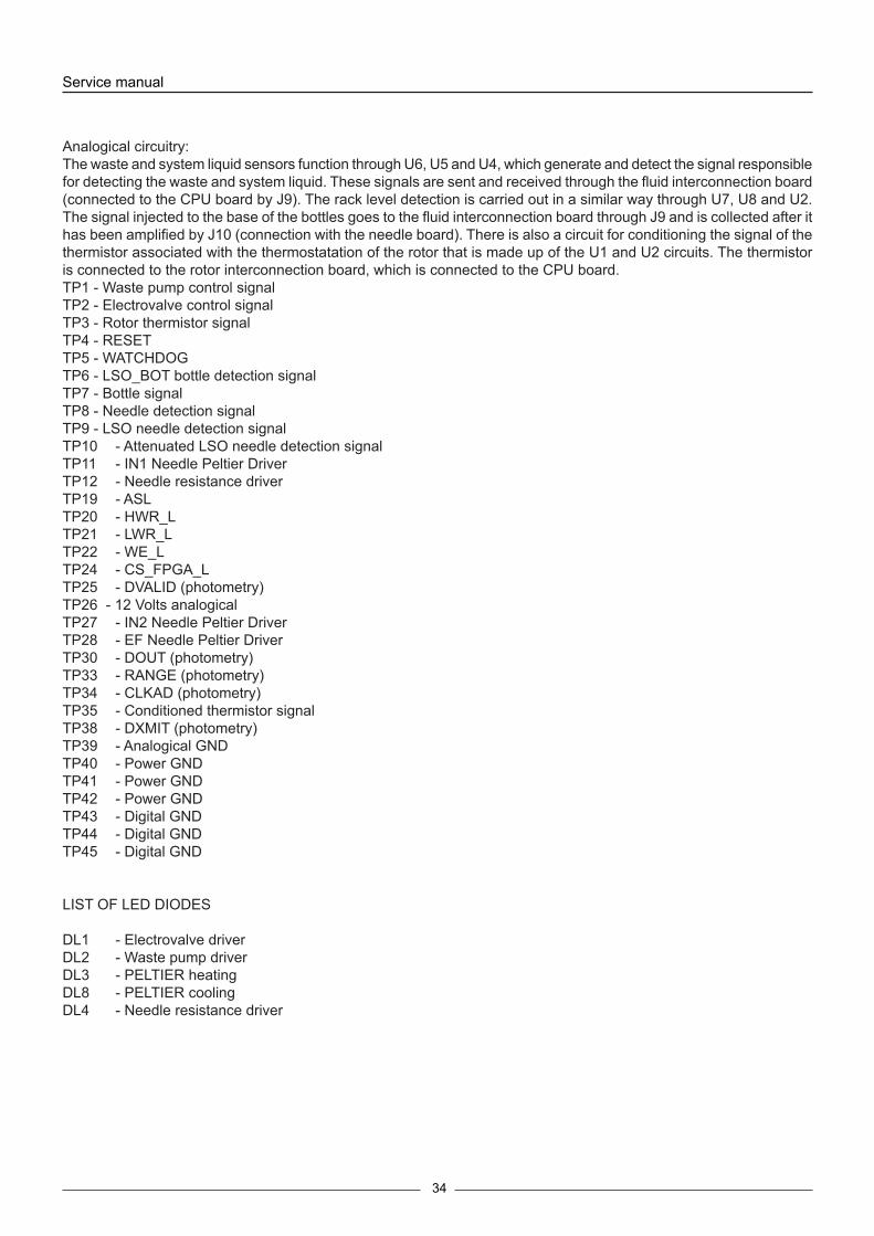
Analogical circuitry:The waste and system liquid sensors function through U6, U5 and U4, which generate and detect the signal responsible for detecting the waste and system liquid. These signals are sent and received through the fluid interconnection board (connected to the CPU board by J9). The rack level detection is carried out in a similar way through U7, U8 and U2. The signal injected to the base of the bottles goes to the fluid interconnection board through J9 and is collected after it has been amplified by J10 (connection with the needle board). There is also a circuit for conditioning the signal of the thermistor associated with the thermostatation of the rotor that is made up of the U1 and U2 circuits. The thermistor is connected to the rotor interconnection board, which is connected to the CPU board.TP1 - Waste pump control signalTP2 - Electrovalve control signalTP3 - Rotor thermistor signalTP4 - RESETTP5 - WATCHDOGTP6 - LSO_BOT bottle detection signalTP7 - Bottle signalTP8 - Needle detection signalTP9 - LSO needle detection signalTP10 - Attenuated LSO needle detection signalTP11 - IN1 Needle Peltier Driver TP12 - Needle resistance driver TP19 - ASL TP20 - HWR_LTP21 - LWR_L TP22 - WE_LTP24 - CS_FPGA_L TP25 - DVALID (photometry)TP26 - 12 Volts analogicalTP27 - IN2 Needle Peltier DriverTP28 - EF Needle Peltier DriverTP30 - DOUT (photometry)TP33 - RANGE (photometry)TP34 - CLKAD (photometry) TP35 - Conditioned thermistor signalTP38 - DXMIT (photometry) TP39 - Analogical GND TP40 - Power GND TP41 - Power GND TP42 - Power GND TP43 - Digital GND TP44 - Digital GND TP45 - Digital GND
LIST OF LED DIODES
DL1 - Electrovalve driverDL2 - Waste pump driverDL3 - PELTIER heatingDL8 - PELTIER coolingDL4 - Needle resistance driver
35

Service manual
36
TP1 - Lamp voltage from 5.75 V <6V TP2 - 12V analogicalsTP3 - 5V digital
List of LED diodes:
D4 - Indicates 5V activatedD2 - Indicates 12V lamp activatedD3 - Indicates 12V analogicals activated
3.2 Power Supply Board (CIIM00015)
This is made up of 2 different switched regulators and 1 voltage line that enable distribution of the power supply in accordance with the requirement of each subsystem.
Connector Function Pins
J1 24 V input 1 - 24V3 - (GND)
J2 Output voltage of 6 V for lamp supply
1 - 12 V3 - GND
J3 Output voltage of 24 V, 12V, 5 V and fan and lamp control input
1 - 36V2 - GND3 - 12V4 - 5V5 - ENABLE LAMP6 - ENABLE FAN
J4, J5 Fan output voltage of 24 V 1 - 24V2 - GND

37

Service manual
38
3.3 Needle Board (CIIM00017)This board conditions the thermistor signal associated with the thermostatation of the needle, the preamplification of the level detection signal and the Z home. It receives, from the needle unit, the thermostatation elements, the ther-mistor and the level signal detected by the needle itself.
The cables that join this board with the CIIM00026-01 board come from this needle.
TP1 - Needle signalTP2 - Output preamplifier needle signalTP3 - Output amplifier thermistor signalTP4 - Thermistor12V - 12V voltage5V - Voltage 5VAGND - GND
Connector Function Pins
J1 CPU board connection (CIIM0026)
1 - GND POWER2 - 12V analogical3 - level sensor 4 - Home Z5 - GND POWER6 - Thermistor 7 - EARTH8 - GND POWER9,10 - Thermo elements.

39

Service manual
40
3.4 Photometry Board (CIIM00027)This board also has the heart of the absorbance measuring system for the samples to be analyzed. It is made up of a photosensor and an associated analogical-digital conversion circuitry (DDC112).
JP1 - soldering bridge - Solder only if the local oscillator and the U4 and U5 scales, respectively, are not present.JP2 - soldering bridge - as per JP1JP3 - soldering bridge - joins together the analogical and digital frames
Connector Function Pins
J3 Photometric board connection CIIM00029) 1 - 12 V2 - GND3 - DVALID4 - DCLK5 - DOUT6 - DXMIT7 - RANGE28 - RANGE1 9 - RANGE010 - TEST11 - CONV12 - GND13 - CLKAD14 - GND15 - GND16 - V DC

41
3.5 XYZ Interconnection Board (CIIM00018)This board interconnects the CP1 board with the X carriage. It distributes the X and Y motor signals and transmits the home signals of the X and Y movements. It also sends the encoder signal to the CPU board.
Connector Function Pins
J1 Connection motor X
J2 Connection motor Y
J3 Connection motor Z
J4 C P U b o a r d c o n n e c t i o n (CIIM00026)
1 - coil 2 motor Y2 - V DC3 - coil 2 motor Y4 - GND5 - coil 1 motor Y6 - encoder7 - coil 1 motor Y8 - home motor X 9 - coil 2 motor Y10 - home motor X11 - coil 2 motor Z12 - GND
J5 C P U b o a r d c o n n e c t i o n (CIIM00026)
1 - coil 2 motor X2 - coil 2 motor X3 - coil 1 motor X4 - coil 2 motor Z5 - coil 2 motor Z6 - coil 1 motor Z
Service manual
42
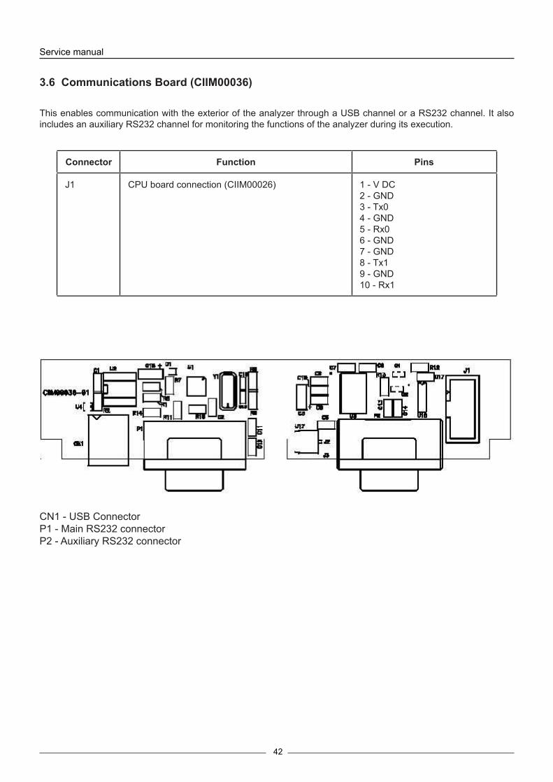
3.6 Communications Board (CIIM00036)
This enables communication with the exterior of the analyzer through a USB channel or a RS232 channel. It also includes an auxiliary RS232 channel for monitoring the functions of the analyzer during its execution.
CN1 - USB ConnectorP1 - Main RS232 connectorP2 - Auxiliary RS232 connector
Connector Function Pins
J1 CPU board connection (CIIM00026) 1 - V DC2 - GND3 - Tx04 - GND5 - Rx06 - GND7 - GND8 - Tx19 - GND10 - Rx1

43
3.7 Rotor interconnection board (CIIM00029)
This interconnects the rotor with the CPU board.
Connector Function PinsJ1 Rotor motor connection
J2 Power connection with board CIIM00026 1 - Coil 2 rotor motor2 - Coil 2 rotor motor3 - Coil 1 rotor motor4 - Coil 1 motor filters5 - Coil 1 rotor motor6 - Coil 1 motor filters7 - Peltier8 - Coil 2 motor filters9 - Peltier10 - Coil 2 motor filters11 - V24 (fans)12 - GND (fans)
J3 Connection with photometry board CIlM00027 1 - 12 V2 - GND3 - DVALID4 - DCLK5 - DOUT6 - DXMIT7 - RANGE28 - RANGE1 9 - RANGE010 - TEST11 - CONV12 - GND13 - CLKAD14 - GND15 -GND16 - V DC
J4 Connection motor filters 1 - Coil 12 - Coil 11 - Coil 22 - Coil 2
J5 Peltier connection 1 - Peltier black 2 - Peltier, red
J6 Fan connection 1 - Fan, black 2 - Fan, red
J7 Connection signal with board CIM00026 1 - 12 V2 - GND3 - DVALID4 - DCLK5 - DOUT6 - DXMIT7 - RANGE28 - RANGE1 9 - RANGE010 - TEST11 - CONV12 - GND13 - CLKAD14 - GND15 - GND16 - V DC17 - V DC18 - Rotor cover sensor 19 - GND20 - Thermistor signal 21 - Home filter drum 22 - GND thermistor 23 - Home rotor24 - Front LED (red) 25 - Front LED (green) 26 - Ambient sensor

Service manual
44
List of LED diodes
DL1 PeltierDL2 Home rotor motorDL3 Home filter motorDL4 Rotor cover
Connector Function Pins
J8 Rotor cover sensor connection 1 - Cable 12 - Cable 2
J9 Thermistor connection 1 - Cable 12 - Cable 2
J10 Front LED connection 1 - Front LED, red 2 - Front LED, black 3 - Front LED, green
J11 Connection Home motor filters 1 - Photo sensor, yellow 2 - Photo sensor, black 3 - Photo sensor, red
J12 Connection Home rotor 1 - Photo sensor, yellow 2 - Photo sensor, black 3 - Photo sensor, red
J13 Connection fans 1 - Fan, black 2 - Fan, red

45
3.9 Pump interconnection board (CIIM00028)
The pump interconnection board interconnects the CPU board with the dispensing pump, the waste pump, the electrovalve, the bottle level sensor and the instrument cover.List of LED diodes
DL1 ElectrovalveDL2 Waste pumpDL3 Home pumpDL4 Instrument cover
Connector Function Pins
J1 Waste sensor 1 - Waste sensor
J2 Connection signal with board CIIM00026 1 - Waste sensor 2 - System liquid sensor 3 - LS/waste signal 4 - Needle liquid detection signal 5 - Home dispensation pump 6 - V DC7 - GND8 - Instrument cover
J3 System liquid sensor 1 - System liquid sensor
J4 LS/waste sensor signal 1 - System liquid signal
J5 Needle liquid detection signal 1 - Needle liquid detection signal
J6 Dispensation pump home 1 - Photo sensor, yellow 2 - Photo sensor, black 3 - Photo sensor, black
J7 Electrovalve 1 - White cable 2 - White cable
J8 Power connection with board CIIM00026 1 - 24 V electrovalve 2 - GND3 - Waste pump 4 - Waste pump 5 - Dispensation pump coil 16 - Dispensation pump coil 17 - Dispensation pump coil 28 - Dispensation pump coil 2
J9 Waste pump 1 - Waste pump, red 2 - Waste pump, black
J10 Waste pump 1 - Coil 12 - Coil 14 - Coil 25 - Coil 2
J11 Instrument cover 1 - Photo sensor, yellow 2 - Photo sensor, black 3 - Photo sensor, red

Service manual
46

47
3.10 Component relation
3.11 Auxiliar channel informationThe rear left part of the instrument is where the communications cables are connected. There are two connections, the COM1 and the COM2.The COM1 is the main connection from the analyser to the computer. This connection should be always present to analyser run propertly.
there are two connection types: A - Cable type USB B - Cable type RS-232
Only connect one cable type.
Component ReferenceHome detector TCST13003 way electrovalve LVM115-6A-2U-1 from SMCCover magnet Neodimio D4x5Lamp 6V 10W Gilway L6402Pump motor NMB23ML-C343V-1Rotor motor NMB17PMKD18VWashing system motor SP600-EC-LC-LFilter wheel motor NMB23ML-C343V-1X motor NMB23ML-C343V-1Y motor NMB17PMKD18VZ motor NMB17PMKD18VRotor peltier TES-06339Probe temperature sensor B57861-S302-F40Rotor temperature sensor B57861-S302-F40Hall efect sensor RELE REED A041 1D 2H 0500 Electronic box fan SUNON KD2406PTS1Rotor fan SUNON KD2404PKS2

Service manual
48
The labeled connector COM2 is the auxiliar connector.This connector is used to communicate with a second serial port in the computer. The function of this cable is to mo-nitor the internal states of the analyser.To show all this information, the user should execute the program: windows HyperTerminal and configure with the following parameters:Programa: Inicio\Todos los programas\accesorios\comunicaciones\hyperterminal
Baud Rate: 38400Número de bits: 8Stop bits: 1Paridad: noneOnces is configured and connected the cable, switch on the analyser. In this moment will appear in the HyperTerminal screen information about the analysers mode and the different executes states. In the initializate mode, the analyser do an internal checking for each element, if someone has any error then in the screen will show the element that fails. The following lines shows an exemple of the instructions during an initialization, (this information could change with the improvements of the firmware) :
BIOSYSTEMS A15
Firmware initialization Firmware Version: A15 User V3.12 Serial Number: 831050311
FLASH functions transferred to RAM Interrupt Vectors transferred to RAM Interrupts enabled
Checking firmware integrity Checking program checksum: Checksum correct! Program Checksum=0x5039 Size=427100
Checking A15 configuration checksum: Checksum correct! Configuration Checksum=0x179C Size=856
Checking A15 configuration backup checksum: Checksum correct! Configuration backup Checksum=0x179C Size=856
Loading A15 Configuration from FLASH Configuration in FLASH is correct
Adjustments loaded:
Temperature correction for Rotor=0.50 Temperature correction for Probe=0.00 System Liquid Detection=30 Waste Detection=29 Sensitivity of level detection=110 Origin X=60 Origin Y=280 Origin Z=430 Tray Reference X=675 Tray Reference Y=10 Washing station X=360 Washing station Y=5 Washing station Z=450 Washing station Ext X=360 Washing station Ext Y=95 Washing station Ext Z=540 Reactions Rotor X=110 Reactions Rotor Y=1044 Reactions Rotor Z=600 Rotor Distance between the dispensation point and the optic system=610 Rotor Position correction regard to the dispensation point=98 Rotor Position correction regard to the optic system=-4 Filters Wheel correction=0
Filters and their Integration Times:
Filter 1=000 Integration Time= 20ms ( 40) Reference Time= 0ms ( 0) Filter 2=340 Integration Time=205ms (400) Reference Time= 0ms ( 0) Filter 3=405 Integration Time= 51ms (100) Reference Time= 0ms ( 0) Filter 4=505 Integration Time= 51ms (100) Reference Time= 0ms ( 0) Filter 5=535 Integration Time= 51ms (100) Reference Time= 0ms ( 0) Filter 6=560 Integration Time= 51ms (100) Reference Time= 0ms ( 0) Filter 7=600 Integration Time= 51ms (100) Reference Time= 0ms ( 0) Filter 8=635 Integration Time= 51ms (100) Reference Time= 0ms ( 0) Filter 9=670 Integration Time= 51ms (100) Reference Time= 0ms ( 0) Filter 10=000 Integration Time= 20ms ( 40) Reference Time= 0ms ( 0)
TI/LB Hystoric:F[01]: 00000000 00000000 00000000 00000000 00000000 00000000 00000000 00000000 00000000 00000000 F[02]: 00000000 00000000 00000000 00000000 00000000 00000000 00000000 00000000 00000000 00000000 F[03]: 00000000 00000000 00000000 00000000 00000000 00000000 00000000 00000000 00000000 00000000 F[04]: 00000000 00000000 00000000 00000000 00000000 00000000 00000000 00000000 00000000 00000000 F[05]: 00000000 00000000 00000000 00000000 00000000 00000000 00000000 00000000 00000000 00000000 F[06]: 00000000 00000000 00000000 00000000 00000000 00000000 00000000 00000000 00000000 00000000 F[07]: 00000000 00000000 00000000 00000000 00000000 00000000 00000000 00000000 00000000 00000000 F[08]: 00000000 00000000 00000000 00000000 00000000 00000000 00000000 00000000 00000000 00000000 F[09]: 00000000 00000000 00000000 00000000 00000000 00000000 00000000 00000000 00000000 00000000 F[10]: 00000000 00000000 00000000 00000000 00000000 00000000 00000000 00000000 00000000 00000000
F[01]: 000 000 000 000 000 000 000 000 000 000 F[02]: 000 000 000 000 000 000 000 000 000 000 F[03]: 000 000 000 000 000 000 000 000 000 000 F[04]: 000 000 000 000 000 000 000 000 000 000 F[05]: 000 000 000 000 000 000 000 000 000 000 F[06]: 000 000 000 000 000 000 000 000 000 000

49
F[07]: 000 000 000 000 000 000 000 000 000 000 F[08]: 000 000 000 000 000 000 000 000 000 000 F[09]: 000 000 000 000 000 000 000 000 000 000 F[10]: 000 000 000 000 000 000 000 000 000 000
Zmax Reference=1130 - Pediatric Offset=0 - 13mm Offset=0 - 15mm Offset=0 - Reagent Offset=0 - Central Reagent Offset=0
A15 Mechanical History
- X axis: 0 Steps - Y axis: 0 Steps - Z axis: 0 Steps - Rotor: 0 Steps - Filter Wheel: 0 Steps - Ceramic Pump: 0 Steps - Washing Station Pump: 0 Cycles - Washing Station Valve: 0 Cycles - Ceramic Pump Valve: 0 Cycles - Lamp: 0 Minutes
A15 Statistics
- Biochemistry Tests: 0 - Turbidimetry Tests: 0 - Biochemistry Bireagent Tests: 0 - Turbidimetry Bireagent Tests: 0 - Predilutions: 0 - Initial/Final Washings: 0 - Washing Solution Washings: 0 - System Liquid Washings: 0 - New Rotor: 0 - Bireagent Contaminations Solved: 0
Setting racks layout
Tray Ref. X=675 => Distance from tray reference to tray corner X=2190 Tray Ref. Y=10 => Distance from tray reference to tray corner Y=30
Absolute position of tray corner X=2865 Absolute position of tray corner Y=-20 Generating Zmax Map:Ok“ CPU settings: MDCR=c4;ABWCR=0;ASTCR=ff“
BioSystems A15“ Hello World“
A15 MAGIC KEYS“
H: Help“ R: Rotor Temperature“ P: Probe Temperature S: Level Scales A: Last A15 Stress Results L: Actual Sensitivity of Level Detection N: Enable Level Detection Debug K: Power Supply On Buzzer Control B: Buzzer On b: Buzzer Off Encoder E: Generate Encoder Error I: Enable Encoder IRQ Rotor Reading 1: Choose Filter + 2: Choose Filter -
9: Start Rotor Readings Notes: Use only in Service Mode after a Base Line Test.“ Rotor Read 1: Choose Filter + 2: Choose Filter - User Mode Test G: Test Notes: Use only after a Worklist in Stand By.“ This tests dumps all the preparations“ parameters received and the photometric“ readings. Finally performs a general test“ of the analizer.“ After this test press New Rotor for continue working.“ DDC112/Photometry D: Choose Mode - DDC112 internal test mode - DDC112 Photometry Mode - Stop +: Integration Time +0.5ms -: Integration Time -0.5ms Notes: Only works in Service Mode This tests performs continuous“ readings with the DDC112.“ Remember stop the test for “ continue working.“
Caution: Dont’t abuse of this functions while the analizer is running.“
<>RxStand by mode!LCTxSRxInicio modo servicio!
Hardware Initialization
Programming FPGA XC2S50PQ208 - Clearing FPGA program memory: OK! - Programing FPGA: OK FPGA XCS50PQ208 is programmed
Initialization of level detection system - Generating Sensitivity Map:OkLevel Detection Mode:Normal
Pediatrico:Rack 1 2 3 4 173 141 129 126 123 125 129 151 161 129 118 115 113 115 125 141 158 128 114 111 108 111 121 138 156 127 113 108 107 110 118 139 156 127 112 108 107 110 117 145 155 126 112 108 106 110 121 146 161 128 113 110 106 112 121 151 160 132 112 111 106 113 121 151 167 133 115 112 108 114 124 156 171 136 117 116 113 119 129 163 177 145 123 122 116 124 136 172 202 160 139 135 133 138 155 190
Tubo 13/15mm:Rack 1 2 3 4 162 141 126 123 119 123 132 147 149 132 115 115 111 115 121 137 145 126 110 111 107 112 115 136 148 127 111 108 106 110 117 136 148 127 112 111 105 110 118 144

Service manual
50
149 128 111 111 107 113 119 145 154 126 113 110 108 111 119 144 155 128 115 111 110 113 124 145 161 130 114 112 110 115 125 148 161 133 117 112 112 116 125 154 169 140 123 121 118 122 133 161 190 155 134 133 128 134 146 176
Reactivos:Rack 1 2 3 4 163 151 152 183 156 141 143 174 152 138 140 173 150 134 137 172 154 135 138 176 156 139 143 181 160 138 145 187 166 145 149 194 173 150 156 204 194 172 173 228
Initializating Motors - Axis Z in HOME - Axis Y in HOME - Axis X in HOME - ROTOR in HOME - FILTERS WHEEL in HOME - CERAMIC PUMP in HOME Motors Initializated
Optics Initialization - Filter correction=0 - Rotor correction=98 Rotor Lect. correction=-4 - Used wells:0
- Check DDC112..OK (FPGA 8Mhz Clock: OFF) - DDC112 test: OK! (Result => 0046387) Optics Initializated
Generating Pattern: 1 1 1 1 1 1 1 1 1 1 1 0 0 0 0 0 0 0 0 0 Generating Gate: 0 0 0 0 1 1 1 1 0 0 0 0 0 0 0 1 1 0 0 0 OK Z Axis Initialization - Axis Z in HOME Z Axis initializated
Penc:111111111000000000| OK
Z Axis Initialization - Axis Z in HOME Z Axis initializated
Probe AA - X:X=Xcal+-1“ - Y:Y=Ycal+0“ AAEnd Peltier Cells and Drivers Test - Probe Peltier Driver Test: Ok! (Not implemented) - Rotor Peltiers Driver Test: Ok!
Hardware Initializated
There are a few keys that work with the Hyperterminal, to press some keys the analyser give information about some element, the following keys has the function:
H: Help, help, shows the help text R: Rotor Temperature, shows the rotor temperature P: Probe Temperature, shows the needle temperatare S: Level Scales, shows the scales mesures in % A: Last A25 Stress Results
L: Actual Sensibility of Level DetectionN: Activate additional information of level detection (only internal use)K: Deactivate the power supplyB: Activate the buzzerb: Deactivate the buzzerE: Generate an encoder error (only internal use)I: Activate the encoder interrupt (only internal use)
1: Increase the filter wheel position2: Decrease the filter wheel position9: Mesure the whole rotor, step by step
G: Once finish a work list, push the G and send to the hyperteminal more detailed information of the work list managemnet
D: Show the mesure depending on the number of key pressed 1st press: activate the internal test DDC112, always show the same count number 2nd press: activate the normal mesure DDC112, show the count number mesured 3th press: stop the DDC112 mesure+: Increase the integration time in 0.5ms-: Decrease the intergration tie in 0.5ms

51
3.12 Interconnection between boardsThe following diagrams show the connections between the boards and the different elements that make up the analyzer.

Service manual
52

53

Service manual
54

55

Service manual
56

57
3.13 Schematic liquid circuit
58
Service manual
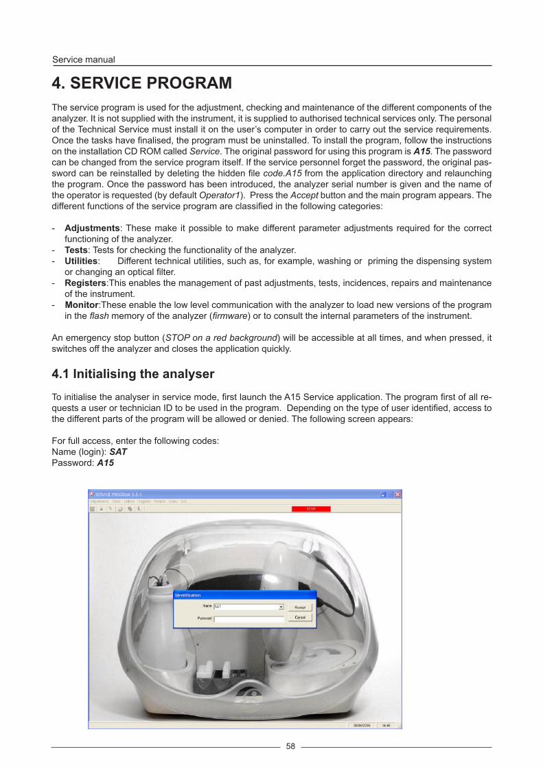
4. SERVICE PROGRAMThe service program is used for the adjustment, checking and maintenance of the different components of the analyzer. It is not supplied with the instrument, it is supplied to authorised technical services only. The personal of the Technical Service must install it on the user’s computer in order to carry out the service requirements. Once the tasks have finalised, the program must be uninstalled. To install the program, follow the instructions on the installation CD ROM called Service. The original password for using this program is A15. The password can be changed from the service program itself. If the service personnel forget the password, the original pas-sword can be reinstalled by deleting the hidden file code.A15 from the application directory and relaunching the program. Once the password has been introduced, the analyzer serial number is given and the name of the operator is requested (by default Operator1). Press the Accept button and the main program appears. The different functions of the service program are classified in the following categories:
- Adjustments: These make it possible to make different parameter adjustments required for the correct functioning of the analyzer.
- Tests: Tests for checking the functionality of the a na ly zer.- Utilities: Different technical utilities, such as, for example, washing or priming the dispensing sys tem
or changing an optical filter. - Registers:This enables the management of past adjustments, tests, incidences, repairs and maintenance
of the instrument.- Monitor:These enable the low level communication with the analyzer to load new versions of the program
in the flash memory of the analyzer (firmware) or to consult the internal parameters of the instrument.
An emergency stop button (STOP on a red background) will be accessible at all times, and when pressed, it switches off the analyzer and closes the application quickly.
4.1 Initialising the analyserTo initialise the analyser in service mode, first launch the A15 Service application. The program first of all re-quests a user or technician ID to be used in the program. Depending on the type of user identified, access to the different parts of the program will be allowed or denied. The following screen appears:
For full access, enter the following codes:Name (login): SATPassword: A15

59
Once the user has been identified correctly, the service program starts to initialise the analyser.
This screen appears when the analyser has finished the previous operations done to enter the SERVICE mode. If the complete hardware of the analyzer is in correct conditions, the result “Hardware initiated correctly» displays. If any hardware element presents an operational problem, it will appear “Hardware not initiated completely” in the screen, and the element that is not working correctly will be shown. In order to close the screen and continue working, you should press the Accept button. In order to get a printed copy of this initialization report, you should press the Print button. NOTE: If an error has been reported and the technician continues working with the service program, he must consider that there is a hardware element that is not working properly.

60
Service manual
4.2. ADJUSTMENTS
These make it possible to make different parameter adjustments required for the correct functioning of the analyzer. All the values to be adjusted have certain limited ranges, indicated by the service program. These values are also given in an appendix at the back of this manual. If, after varying any of the parameters within its permitted range, the analyzer is not tuned up, it indicates that the corresponding system is broken and in need of repair.
4.2.1. Adjustment of the needle thermostatation system
This screen adjusts the needle thermostatation in such a way that the dispensing temperature of the reactions
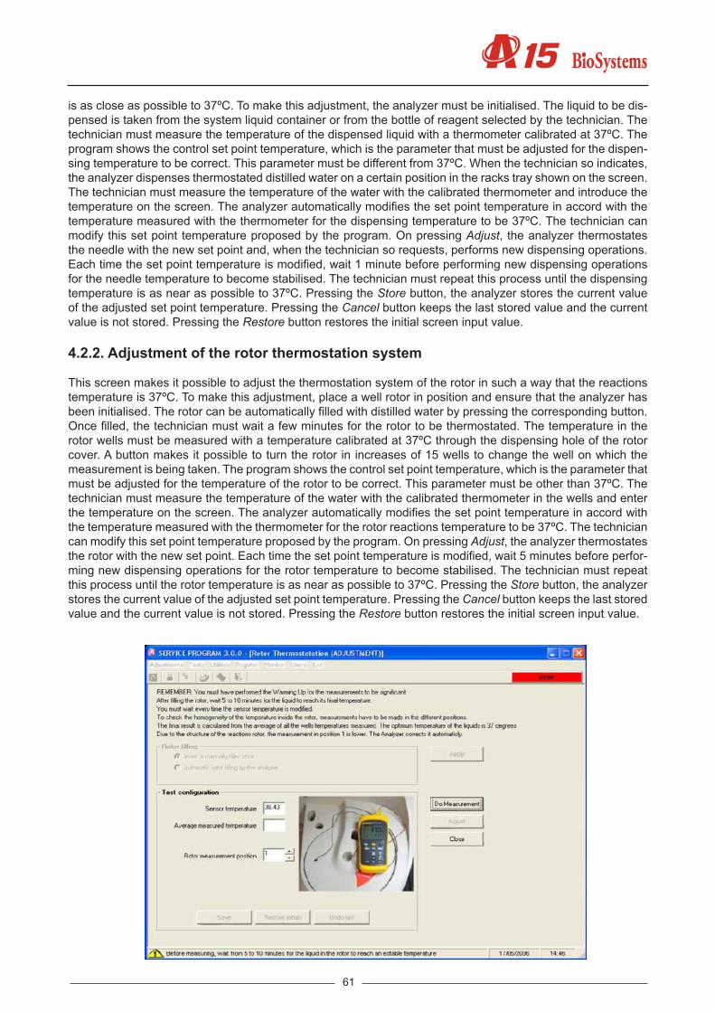
61
is as close as possible to 37ºC. To make this adjustment, the analyzer must be initialised. The liquid to be dis-pensed is taken from the system liquid container or from the bottle of reagent selected by the technician. The technician must measure the temperature of the dispensed liquid with a thermometer calibrated at 37ºC. The program shows the control set point temperature, which is the parameter that must be adjusted for the dispen-sing temperature to be correct. This parameter must be different from 37ºC. When the technician so indicates, the analyzer dispenses thermostated distilled water on a certain position in the racks tray shown on the screen. The technician must measure the temperature of the water with the calibrated thermometer and introduce the temperature on the screen. The analyzer automatically modifies the set point temperature in accord with the temperature measured with the thermometer for the dispensing temperature to be 37ºC. The technician can modify this set point temperature proposed by the program. On pressing Adjust, the analyzer thermostates the needle with the new set point and, when the technician so requests, performs new dispensing operations. Each time the set point temperature is modified, wait 1 minute before performing new dispensing operations for the needle temperature to become stabilised. The technician must repeat this process until the dispensing temperature is as near as possible to 37ºC. Pressing the Store button, the analyzer stores the current value of the adjusted set point temperature. Pressing the Cancel button keeps the last stored value and the current value is not stored. Pressing the Restore button restores the initial screen input value.
4.2.2. Adjustment of the rotor thermostation system
This screen makes it possible to adjust the thermostation system of the rotor in such a way that the reactions temperature is 37ºC. To make this adjustment, place a well rotor in position and ensure that the analyzer has been initialised. The rotor can be automatically filled with distilled water by pressing the corresponding button. Once filled, the technician must wait a few minutes for the rotor to be thermostated. The temperature in the rotor wells must be measured with a temperature calibrated at 37ºC through the dispensing hole of the rotor cover. A button makes it possible to turn the rotor in increases of 15 wells to change the well on which the measurement is being taken. The program shows the control set point temperature, which is the parameter that must be adjusted for the temperature of the rotor to be correct. This parameter must be other than 37ºC. The technician must measure the temperature of the water with the calibrated thermometer in the wells and enter the temperature on the screen. The analyzer automatically modifies the set point temperature in accord with the temperature measured with the thermometer for the rotor reactions temperature to be 37ºC. The technician can modify this set point temperature proposed by the program. On pressing Adjust, the analyzer thermostates the rotor with the new set point. Each time the set point temperature is modified, wait 5 minutes before perfor-ming new dispensing operations for the rotor temperature to become stabilised. The technician must repeat this process until the rotor temperature is as near as possible to 37ºC. Pressing the Store button, the analyzer stores the current value of the adjusted set point temperature. Pressing the Cancel button keeps the last stored value and the current value is not stored. Pressing the Restore button restores the initial screen input value.

62
Service manual
4.2.3. Adjustment of the positioning of the operating arm
This screen makes it possible to adjust the horizontal positioning (X, Y) of the arm. The arm housing must be removed to see the position of the needle. Before making the adjustments, visually check the verticality of the needle. If necessary, carefully straighten it up ensuring you do not damage it. On the screen, select the point at which you wish to adjust the horizontal positioning. On pressing the Adjust button the arm initialises and positions itself over said point. The technician has buttons to move the arm step by step over the horizontal plain (X, Y) and vertically (Z). The arm can also be moved introducing a certain number of absolute movement steps. These absolute movements of the arm must be made with the needle at its highest position so as not to damage it (coordinate 0). The technician must lower the needle to the adjustment point and adjust its horizontal position. When the position is satisfactory, save the current coordinates (X, Y) by pressing the Store button. Pressing the Cancel button keeps the last adjustment values stored. Pressing the Restore button restores the initial screen input values. At all times, the screen shows the current coordinates of the arm for the selected point, the last coordinates stored and the initial screen input coordinates, as additional information for the te-chnician. The technician may repeat the procedure to adjust the positioning of the arm at the different possible adjustment points. These points are as follows:
(1) Origin. Vertex of the self-centering plate of the needle.(2) Rack tray Adjust point located in the right part at rear of the tray(3) Washing station. Centre of front part of washing station.(4) Reactions rotor. Dispensing point on the rotor reactions cover.(5) Zmax (on tray reference) The same point of rack tray
If you select the point of origin, automatic adjustment is possible in this position by pressing an AutoAdjustment button (the process can take around 3 minutes).
4.2.3.1 Adjustment of X, Y and Z position for reagent and pediatric racks
Note: the pediatric rack is a 15 diameter rack with pediatric adapters and wells
This process is used to adjust each rack individually in the three coordinates, X, Y and Z as much for pediatric as for reagent racks. For that, each rack of the tray will be adjusted to positions 1 and 12 for pediatric racks and 1 and 10 for the reagent ones.

63
There are two tools to carry out the adjustment process: one to adjust the reagent rack and the other for the pediatric rack.
In order to carry out this XYZ rack adjustment, you may use the screen or keyboard buttons. Movements using keyboard:- X axis movements: right and left cursor button- Y axis movements: up and down cursor button- Z axis movements: page up and page down button
Adjustment process using the tool
Place the tool as per the photograph.Tools have been designed so that the square (pointed with arrows in the upper photograph) corresponds with the position of the center of the well or bottle. And so that the tool lower level corresponds with the well or bottle bottom.
Steps to follow:
1. Select the type of adjustment which you wish to carry out: adjustment of the tray (XYZ) of the pediatric diameter rack or of the reagent rack.
2. Press the button Adjust.

64
Service manual
3. Activate the option Adjust with the tool4. Select the number of rack to start the adjustment process. By default, it starts with number 1.5. Place the rack in the selected position, place the tool in the well 1 of the rack with and press Start.6. Probe will automatically descend to a distance over the tool, in order to avoid colliding with it. If necessary,
move the probe with XY movements (screen or keyboard) to the center of the tool opening. Always press Accept (although XY movements were not necessary)
7. The probe will descend some further steps through the tool opening.
From this position of approach, you may start the adjustment of values:
8. Move the probe just by X movements (screen or keyboard) until the probe touches the tool. When touching the tool, this will make an acoustic warning. Press Accept X adjustment.
9. The new adjusted X value will appear in the upper table.10. The probe will automatically come back to the center of the tool opening.11. Move the probe just by Y movements (screen or keyboard) until it touches the tool. When touching the tool,
this will make an acoustic warning. Press Accept Y adjustment.12. The new adjusted Y value will appear in the upper table.13. The probe will automatically come back to the center of the tool opening and will descend some further
steps.14. Move the probe just by Z movements (screen or keyboard) until it touches the tool lower part. This will make
an acoustic warning. Press Accept Z adjustment.15. The new adjusted Z value will appear in the upper table.16. The arm will automatically move to position 10 or 12, depending on the type of rack selected. Repeat steps
6 to 14.17. Once the adjustments in position 10 or 12 are made, the arm is parked so the rack can move.18. Place the rack in the following position of the tray, press Start. Repeat steps 6 to 14 to carry out the ad-
justments in the every position of the rack tray.19. Once the adjustments are finished, they have to be kept in the instrument, so press Save.
Adjustment process without using tool
1. Select the type of adjustment which you wish to carry out: adjustment of the tray (XYZ) of the pediatric diameter rack or of the reagent rack.
2. Press the button Adjust.3. Deactivate the option Adjust with the tool4. Select the number of rack to start the adjustment process. By default, it starts with number 1.5. Place the rack in the selected position, place the well or bottle in well number 1 of the rack and press Start.6. Probe will automatically descend to a distance over the well/bottle, in order to avoid colliding with it. Then,
probe has to be put into the well/bottle just a little. In order to do so:- If probe is not centered in XY and out of the well or bottle opening: move the probe just by XY movements
(screen or keyboard) before carrying out Z movements to get the probe down.- Then, get the probe slightly down with Z movements (screen or keyboard) just to make the adjustment
of the center easier.
From this position of approach, you may start the adjustment of values:
7. Adjust the well/bottle center: to do so, move the probe by X and Y movements (screen or keyboard)8. Adjust the bottle or well bottom: to do so, move the probe by Z movements (screen or keyboard) until it
reaches the bottom. To check it: move the bottle/well up and down.9. To finish the XYZ adjustment, press Accept.10. The new adjusted XYZ values will appear in the upper table. (Nevertheless, they are not saved in the ins-
trument yet).11. The arm will automatically move to position 10 or 12, depending on the type of rack selected. Repeat steps
6 to 9.12. Once the adjustments in position 10 or 12 are carried out, the arm is parked so the rack can be moved.13. Place the rack in the following position of the tray, press Start. Repeat steps 6 to 9 to carry out the adjustments
in the every position of the rack tray.14. Once the adjustments are finished, adjustments have to be kept in the instrument, so press Save.

65
Adjustment of Z-axis of tubes When the adjustment of the tray of pediatric racks is selected, it appears another adjustment: the Z relation between pediatric and tube. In order to carry out this adjustment, follow the following steps:
1. Place a diameter 15 rack in position 2 of the tray, with a tube in rack position 1.2. Insert a value in the box of Z pediatric-tube relation. This value shows the separation steps between a pe-
diatric well and a primary tube.3. Press Start. 4. Check that the probe has not collided to the bottom of the tube.5. Move the probe by Z movements (screen or keyboard) until it reaches the well bottom.6. Once the adjustments are finished, adjustments have to be kept in the instrument, so press Save.
4.2.4. Adjustment of the positioning of the rotor
This screen enables the adjustment of the positioning of the rotor with regard to the dispensing point and the optical system. One or the other is selected by means of two different tabs.
4.2.4.1. Centering of the rotor with regard to the dispensing point
The analyzer initialises the rotor and positions the first rotor well at the currently programd dispensing position. The technician has buttons to move the rotor step by step to adjust, if necessary, this position and buttons for finer adjustment of the X coordinate over the dispensing point. At all times, the screen shows the current dis-pensing coordinate on the first well and of the X axis position, the last coordinate stored and the initial screen input coordinate, as additional information for the technician. When this is satisfactory, the current coordinate of the dispensing point of the first well can be stored by pressing the Store button. Pressing the Cancel button keeps the last stored value and the current value is not stored. Pressing the Restore button restores the initial screen input value.
4.2.4.2. Centering of the rotor with regard to the optical system
This adjustment is necessary only if the Rotor Centering Adjustment has been carried out with regard to the dispensing point (4.1.4.1.). This adjustment must be made with the rotor cover in position. The analyzer initia-lises the rotor and fills the first 3 wells of the rotor with distilled water. Next, step-by-step optical readings are

66
Service manual
made through these wells at the wavelength selected by the technician. Once the readings have ended, the program shows a graph of the light intensity measured on the rotor steps. On this graph, the program indica-tes at which points the optical readings are made on each of the 3 wells when the analysis is made, with the coordinate of the reading point of the first well currently programd in the analyzer. If necessary, the technician can move the reading points over the graph jointly using two buttons. The optimum reading point is that which globally maximises the light intensity for the three wells. At all times, the screen shows the current coordinate of the reading in the first well and the last coordinate stored, as additional information for the technician. When the position is satisfactory, the current coordinate of the reading point of the first well can be stored by pressing the Store button. Pressing the Cancel button keeps the last stored value and the current value is not stored.
4.2.5 . Adjustment of the positioning of the filter wheel
This adjustment must be made with the rotor cover in position. The analyzer initialises the rotor and the filter wheel and fills the first rotor well with distilled water. Next, it takes optical readings through this well, turning the filter wheel step by step, with a certain integration time as indicated by the technician (the concept of integration time is explained in the section on photometric adjustments). Once the readings have ended, the program shows a graph of the light intensity measured on the steps of the filter wheel. On this graph, the program indicates at which points each of the filters is positioned when optical readings are taken when the analysis is carried out, with the coordinate of the positioning of the filter 0 currently programd in the analyzer. If necessary, the technician can move the reading points over the graph jointly using two buttons. The optimum reading point is that which globally maximises the light intensity for all the filters. At all times, the screen shows the current coordinate of the filter 0 and the last coordinate stored, as additional information for the technician. When the position is satisfactory, the current coordinate of the positioning of the filter 0 can be stored by pressing the Store button. Pressing the Cancel button keeps the last stored value and the current value is not stored.

67
4.2.6. Adjustment of the level control scales
This screen makes it possible to set the level control scales with the empty waste and distilled water containers (0% capacity) and when they are full (100% capacity). The maximum capacity of the containers is approximately 3L. The technician must choose whether he wishes to set the distilled water or waste container scales, with the corresponding container full or empty. According to the requested adjustment, the corresponding container, full or empty, must be placed in position and the Adjust button pressed. Based on the settings made, the analyzer automatically adjusts the scales. On pressing the Store button, the analyzer saves the new values of the adjus-ted parameters. Pressing the Cancel button keeps the last stored values and the current values are not stored.

68
Service manual
4.2.7. Adjustment of the level detection sensitivity
This screen allows fitting the sensitivity of the capa city level detection system of the probe. In order to make the adjustment, first of all you have to select the typs of racks: metal filled racks (grey color) or plastic racks (black color).Then place on it the following configuration of racks and samples:
• Paediatric Rack: place 4 paediatric glasses in positions 5, 6, 17 and 18 with 150 uL of liquid system. • Rack of 13/15mm sample: place 4 tubes in positions 5, 6, 17 and 18 with 500 uL of liquid system. • Rack of reagents: place 2 bottles of 20mL in positions 5 and 6 with 2mL of liquid system.
It is possible to see a graphic with the position of the tubes and racks in the screen photo. When pressing the Adjust button, the arm takes some sensitivity readings automatically until detecting the water in each one of the tubes. Once this operation is finished, the arm is parked in its original position and it shows the sensitivity results of each one of the tubes. Move rack to position 5 and repeat the adjustment. Once these second rea-dings are finished, the program calculates the average of all sensitivities; the result is the average sensitivity. The technician should notice that the sensitivity values of each tube have to be similar; otherwise, he should repeat the whole measurement.Repeat this adjustment per each rack type. The sensitivity value can also be introduced manually for each rack in the corresponding box.
Pressing the button Save, the analyser saves the new adjusted sensitivity value. Pressing the button Close, the old value stays. Pressing the button Restore, the initial value of entry to the screen is restored. A manual sensitivity value can be inserted in the corresponding box.
4.3. TESTSVarious tests make it possible to check that the different components of the analyzer function correctly.
4.3.1. Motor tests
Through these tests, the technician can check the correct functioning of all the analyzer motors step by step. The screen makes it possible to choose the motor to be tested and the test that is to be carried out. The analyzer uses the following motors step by step:- X axis of the operating arm.- Y axis of the operating arm.- Z axis of the operating arm.

69
- Dispensing pump- Rotor- Filter wheel
All the motor tests can be performed without the covers and housing of the analyzer. After the verifications, the operating arm always returns to its resting position. To test the motor of the dispensing pump, the arm is positioned over the washing station. It is convenient for the dispensing system to be primed so that the piston does not function dry. The following is a description of the different tests that can be performed.
4.3.1.1. Initialization test
This test verifies the start detector of each of the motors.
4.3.1.2. Movement test
This test displaces any of the mobile components to the desired point along its range of functioning, introducing the corresponding absolute coordinate or moving it step by step. The speed and acceleration of the movement are those used in the normal functioning of the analyzer.

70
Service manual
4.3.1.3. Loss step test
This test makes it possible to check if a motor misses steps when performing a certain sequence of movements. The test can be carried out with the speed and acceleration used in the normal functioning of the analyzer or with these magnitudes increased by 10% to check the functioning safety margin.
4.3.1.4. Stress mode test
This test makes it possible for a certain sequence of movements to be performed continually. The technician can program the duration of the test, which can be cancelled at any moment. Depending on the motor selected, there is a minimum stress mode time (but in no case is it higher than 50 seconds).
4.3.1.5. Z axis secu ri ty systems test
The Z axis of the operating arm has an encoder to detect if there have been missed steps as a result of a co-llision with the needle. In the case of a power failure, a mechanical system automatically raises the needle. On selecting the corresponding options, the analyzer checks the functioning of each of these devices.

71
4.3.1.6 Maximum Z verification test
This test checks that the needle does not collide with the bottles on the rack tray. Select the rack type (reagent, paediatric, 30 mm or 15 mm), the position of the rack on the tray and the position of the bottle or well on the rack.Press the Start button to move to the selected position and check if the needle collides with the bottle or well or if there is space between the needle and the bottle. Repeat the process in the positions required by the user.
4.3.2. Diaphragm pumps and electrovalves test
The analyzer uses a 3-way electrovalve to manage the dispensing operations. The washing system of the needle uses a 2-way electrovalve and two diaphragm pumps. The screen makes it possible to choose the device to be tested and the test that is to be carried out. The devices that can be tested independently are:- 3-channel electrovalve of the dispensing pump.- 2-channel electrovalve of the washing system.- Washing system diaphragm pumps

72
Service manual
To carry out these tests, the dispensing system should be primed. The following is a description of the different tests that can be performed.
4.3.2.1. Functioning test
This test makes it possible to manually switch the selected device.
4.3.2.2. Stress mode test
This test makes it possible for a certain sequence of device switching to be performed continually. The technician can program the duration of the test, which can be cancelled at any moment.
4.3.3. Needle self-centering system test
This test makes it possible to check the functioning of the needle self-centering system. During its initialisation, the analyzer uses this system to check the presence of the needle and its verticality and automatically correct small deviations. The test consists of simply running this process. The technician can remove the housing of the arm to observe the test. On the finalisation of the test, the program shows the deviation (x, y) found in the motor steps.
4.3.4. Needle level detection system test
This test checks the functioning of the system for detecting the capacity of the needle in bottles of reagent and sample tubes. This test checks the functioning of the system for detecting the capacity of the needle in reagent bottles and sample wells. The test can be performed in any position on the tray.First select the rack type, then the position of the rack on the tray and, finally, the position of the bottle/well on the rack. Press the Test button and the program will move the arm to the indicated position and check whether or not liquid is detected, depending on whether the bottle is full or empty.Repeat the test as many times as the user considers necessary.

73
4.3.5. Needle thermostatation system test
This screen makes it possible to check that the dispensing temperature of the reactions is around 37ºC. To make this adjustment, the analyzer must be initialised. The technician must measure the temperature of the dispen-sed liquid with a thermometer calibrated at 37ºC. The program shows the set point temperature of the current control. This parameter must be different from 37ºC. When the technician so indicates, the analyzer dispenses thermostated distilled water on a certain position in the racks tray shown on the screen. The technician must measure the temperature of the water with the calibrated thermometer and introduce the temperature on the screen. The program indicates if the temperature measured is within the tolerated error margins and stores this value for the test result reports. The liquid to be dispensed is taken from the system liquid container or from the bottle of reagent selected by the technician.

74
Service manual
4.3.6. Needle rotor thermostatation system test
This screen makes it possible to check that the temperature of the rotor reactions is 37ºC. To make this test, the analyzer must be initialised. The methacrylate rotor can be automatically filled with distilled water by pressing the corresponding button. Once filled, the technician must wait a few minutes for the rotor to be thermostated. The temperature in the rotor wells must be measured with a temperature calibrated at 37ºC through the dis-pensing hole of the rotor cover. A button makes it possible to turn the rotor in increases of 15 wells to change the well on which the measurement is being taken. The program shows the set point temperature of the current control. This parameter must be other than 37ºC. The technician must measure the temperature of the water with the calibrated thermometer in the wells and enter the temperature on the screen. The program indicates if the temperature measured is within the tolerated error margins and stores this value for the test result reports.
4.3.7. Photometry tests
This screen contains a set of tests to check the functioning of the optical system. The tests are classified under different tabs. First of all, the base line and darkness count tests must be made in order to be able to carry out the remaining tests. To perform these tests, the analyzer must be initialised.
The optical system has a photodiode that generates an electrical current proportionate to the light intensity on it. time. An AD converter converts the accumulated load into a digital value called count number, between 0 and 1048576. During normal functioning, the analyzer automatically adjusts the integration time for each filter when the analysis begins and after initialisation. When the first photometry test is performed, the integration times are also automatically adjusted. These times are adjusted in such a way that the count number of the base line for each wavelength is as near as possible to 950000. In this way, the dynamic range of the detection system is adapted to the light intensity present at each wavelength. The filter wheel has 10 positions. Position 0 must always contain a covered filter so that the analyzer can perform the darkness adjustment. Positions 1 to 9 can be used for optical filters.
4.3.7.1. Base line and integration times
When this test is run for the first time, the analyzer fills the first 3 rotor wells with distilled water. The analyzer automatically adjusts the integration times and makes a base line with each of the available filters in each of the 3 wells. The program shows the current integration times for each of the filters and the average for the 3

75
wells of the count numbers obtained with each filter. The screen shows the corresponding alarms in the case of anomaly. It is also possible to access a screen where it is possible to manually vary the integration times to check their effect on the count numbers. And another screen where it is possible to assign calculated in-tegration times as reference integration times for each filter. This screen is recommended when a filter or the lamp is physically changed. After performing the test, the analyzer continues to take optical readings using the automatically adjusted integration times.

76
Service manual
4.3.7.2. Darkness counts
The program shows the current integration times for each filter. On running the test, the analyzer positions the covered filter and measures the darkness counts with each of the integration times. Each time an optical reading is taken, the analyzer subtracts these darkness counts from the count numbers measured to obtain the light intensity. The program shows the values obtained and issues the corresponding alarms in case of anomaly. The values should be around 4100 - 4300. All the count numbers shown by the tests given as follows have the darkness counts subtracted.
4.3.7.3. Repeatability without moving the filter wheel
To perform this and the following tests, the base line and darkness count test must have first of all been perfor-med. This test takes absorbance readings during 1 minute with the filter wheel in fixed position. The technician can choose the rotor well on which he wishes to take the readings and fill it with the liquid he desires. He can choose which wavelength he wishes to use. The test can also be performed with the filter covered. When the readings end, the screen graphically displays the count numbers obtained and the absorbances with regard to the corresponding base lines. The program also shows the averages and/or standard deviations of the count numbers and the absorbances.

77
4.3.7.4. Stability
This test takes absorbance readings during 30 minute with the filter wheel in fixed position. The technician can choose the rotor well on which he wishes to take the readings and fill it with the liquid he desires. He can choose which wavelength he wishes to use. The test can also be performed with the filter covered. The test can be cancelled at any time. When the readings end, the screen graphically displays the count numbers obtained and the absorbances with regard to the corresponding base lines. The program also shows the averages and/or standard deviations of the count numbers and the absorbances.
4.3.7.5. Repeatability moving filter wheel
This test takes absorbance readings during 10 minute moving the filter wheel randomly. The technician can choose the rotor well on which he wishes to take the readings and fill it with the liquid he desires. The test can be cancelled at any time. When the readings end, the screen graphically displays the count numbers obtained and the absorbances for each filter with regard to the corresponding base lines. The program also shows the averages and/or standard deviations of the count numbers and the absorbances for each filter.

78
Service manual
4.3.7.6. Absorbance measurement
This test enables individual absorbance readings. The technician can choose the rotor well on which he wishes to take the readings and fill it with the liquid he desires. He can choose which wavelength he wishes to use. The screen shows the count number obtained, the absorbance with regard to the corresponding base line, the value of the base line.
4.3.7.7. Reactions rotor check
The user can use this test to check the optical status of a reactions rotor. He or she can choose the optical filter with which the test is to be performed. The technician must place the rotor in the analyzer and press the Test button. If the Automatic Fill option has been chosen, the analyzer fills the 120 rotor wells with distilled water and then makes a base line on each well with the chosen filter. The analyzer graphically displays the absorban-ces related to the average of all the wells and tells the technician the state of the rotor (optimal, adequate or unusable). After the test, the user must remove the rotor of the analyzer, empty it and dry it completely before using it for analyses.

79
4.3.8. Level control scales test
This screen makes it possible to check the functioning of the level control scales of the waste and distilled water containers. The technician must select which scales he wishes to check and place a certain amount of liquid in the corresponding container. On pressing the Test button, the screen shows the level of liquid measured by the analyzer(only 0 % and 100%)
4.3.9. Covers detection test
This test makes it possible to check the functioning of the different detectors incorporated in the analyzer.- Open detector of the general cover of the analyzer. Rotor cover presence detector.
The technician can manipulate the corresponding components, for example, open and close the cover of the analyzer and the screen shows the state of the detectors in each case.

80
Service manual
4.3.10. PC-Analyzer communications channel test
On pressing the Test button, the computer attempts to establish communication with the analyzer. The program tells the technician if it has been possible or not.The technician can select Automatic Configuration or Manual Configuration. In the case of the latter, he can define the Port and the Speed.
4.3.11. Global stress mode of the analyzer
This test makes it possible to continually reproduce work cycles of the analyzer similar to those made during the preparation and reading of reactions in a normal working routine, but dispensing at the washing station instead of the rotor. It is necessary for the dispensing system to be primed so that the piston does not function dry. All the racks must be removed from the racks tray. This test can be made without the covers and housing of the analyzer. The technician can program the number of cycles he wishes (1 cycle = 15 seconds). The test

81
can be cancelled at any time.Once the test has been launched, the screen provides regular information about the current status of the pro-cess. If an error occurs during the process, the test ends and the screen displays a message indicating the element causing the error. Partial stressing of the elements of the analyser is possible. The following elements can be stressed partially:• X axis• Y axis• Z axis• Reactions rotor• Filter wheel• Dispensation pump• Membrane pumps• 2-way electrvalve• 3-way electriovalve
4.3.12. Photometry tool
This option is used with the Photometry tool (AC15222). It is used for automate the reading process of the tool.To use the photometry tool folow the next stetp:1. Switch on the analyzer.2. Run the service programme. (The older version to use the tool is the 4.1)3. Left the analyzer switch on initialized with the service programme for 20 minutes, to preheat the lamp.4. Select the test menu and Photometry tool option.5. Press the Load Parameters button.6. Insert the CD-ROM and select the file ReferenciaUtilFotometria.bin. Push Accept button.7. Insert the tool (1) in the place of the rotor.8. Press the Read ABS button.9. Press the Report button to print the results report.

82
Service manual
4.4. UTILITIES The program contains various technical utilities. These utilities are also accessible from the user program.
4.4.1. Disassembly of the dispensing needle
On clicking on the Disassemble Needle button, the operating arm positions itself over the rack tray. The program alerts the technician to remove any object positioned under the arm. On clicking OK, the needle descends and the technician can remove it to work with it or change it. To remove the needle, unscrew it by holding the

83
top fitting. If, while handling the needle, the carriage rises due to the pressure made by the technician, press the Lower Needle button for the needle to descend once again. Once the needle has been reassembled on the analyzer, press the Park button for the needle to rise. It performs the self-centering test and the arm finally returns to its parked position. These operations must be done with utmost care since they are carried out with the analyzer cover open and the needle may be contaminated. Laboratory gloves must always be used.
4.4.2. Fluid system supply
On pressing the Test button, the analyzer fills the conduits of the dispensing system and the washing station with distilled water. To perform this operation, the operating arm is moved to the washing station. The technician can choose whether he wishes to prime the dispensing system, the washing system or both.

84
Service manual
4.4.3. Cleaning of the dispensing system
On pressing the Wash button, the analyzer washes the dispensing system internally and externally. To perform this operation, the operating arm is moved to the washing station. The technician can choose between perfor-ming the wash with distilled water or wash solution. In the case of the latter, the analyzer asks the technician to place a bottle of wash solution in stead of the distilled water container or to fill the latter with wash solution. Once the wash has been performed, the analyzer asks for the distilled water container to be put back in position. Finally, the analyzer primes the system with distilled water.
4.4.4. Changing the lamp
When entering the screen, it is possible to choose between: Changing or checking the lamp. When a new lamp is installed, this utility must be used to notify the analyzer that the lamp has been changed and optimize

85
the luminosity of the photometric system. The lamp must be changed with the analyzer in sleeping mode. If the analyzer is on standby mode, the program shuts it down automatically. The lamp must never be touched with fingers. Once the new lamp has been installed and the covers of the optic and rotor put back, access the change lamp utility and press the Test button. The program starts up the analyzer, checks the light intensity of the optical system, shuts down the analyzer and then requests the technician to remove the lamp holder again and replace it again turning it 180º on the axis of the lamp. If the temperature of the lamp holder is high, wait until it cools down or use pincers to hold it. The program starts up the analyzer again, measures the light intensity of the optical system again, compares the light intensity in both possible positions and chooses the greatest luminosity. If it is the current position, it tells the technician that the test is complete. If the best position were the previous one, the program shuts down the analyzer and asks the technician to remove the lamp holder and replace it, turning it 180º on the axis of the lamp, returning the lamp to its initial position. If the option selected at the beginning was to Check the Lamp, the process is the same but without shutting down the analyzer at the beginning.
4.4.5. Configuration of the filter wheel
This screen enables the modification of the analyzer filter wheel. The wheel has 10 positions. Position 0 must always contain a covered filter so that the analyzer can perform the darkness adjustment. Positions 1 to 9 can be used for optical filters. All the positions of the wheel must be occupied for it to work correctly. The positions that do not contain an optical filter must be occupied by a covered filter. The analyzer includes as standard 8 optical filters in positions 1 to 8 and two covered filters in positions 0 to 9. If one of the filters is to be changed, select the desired position of the wheel and press the Change Filter button. The analyzer automatically posi-tions the filter wheel appropriately so that the technician can change the filter through the window of the optical system. Next, if it is different, introduce the wavelength of the new filter that has been installed. If the filter is covered, introduce value 0. On closing the screen, the analyzer asks if the filters have actually been physically changed and a series of warnings are given to the technician telling him he must bear in mind whether or not he has changed a filter.
4.4.6. Demonstration mode
On pressing the Start button, the analyzer activates some of its mobile components, imitating functioning during a work routine. The activated mechanical components are the operating arm, the reactions rotor and the filter wheel. On pressing the Cancel button, the analyzer finishes the current cycle and returns to its rest position.

86
Service manual
4.4.7 Read/load adjustments and cycles
From this screen, it is possible to read the current adjustments that the analyser is using by pressing the button Read Adjustments. It is allowed to save these adjustments in a file. The technician selects the name and location of this file. Also from this same screen and with the button Load Adjustments, the technician is allowed to select an ad-justment file and to load it in the analyzer. Once the adjustment loading is made, the analyser turns off and the application is closed. When reinitiating the application, the new loaded adjustments will be already active.From the firmware version 2.80, the programme counts the number of cycles of each element and the task of the analyser. From this menu, it is possible to read the cycles completed by the analyser. The screen displays the said cycles with the corresponding units.

87
The programme automatically saves a copy of the adjustments and cycles read in a file. This file is located in the following folder:
c:\Program files\A15 Service\Adjustments\
When a physical element of the analyser has to be changed, e.g. the Z axis belt, the counter must be reset to zero for it to correspond to the number of cycles actually stored in the analyser. To perform this operation, select the box of the element that is to be initialised and enter the number of cycles in the enabled box. Then press the Load cycles button.Using the Load adjustments button, this screen also enables the technician to select an adjustments file and load it in the analyser. When the adjustments are loaded, the cycles are also loaded. Perform this operation when a CPU board has to be changed. This avoids having to completely readjust the analyser; only the following sections will have to be readjusted:• Scales• Level detection sensitivity• Needle thermostatation• Rotor thermostatation
4.4.8 Change the rotor type
In this screen the type of rotor is introduced. Each rotor comes labelled with a letter in its top part. Select in this screen the type of rotor to use. For rotors marked with A letter, only select the letter. For the rotors marked with other letters, select OTHERS and then introduce the light path that will come it within the box of rotors or of the distributor.

88
Service manual
4.5. REGISTERThis enables the management of past adjustments, tests, incidences, repairs and maintenance of the instrument.
4.5.1. Introducing the analyzer serial number
The technician can enter the analyzer serial number so that it appears on printed service reports. If an ente-red serial number is changed, the service records are reinitiated. In this case, the technician can store all the previous data in a file.The technician can enter his name so that it appears on the printed service reports.
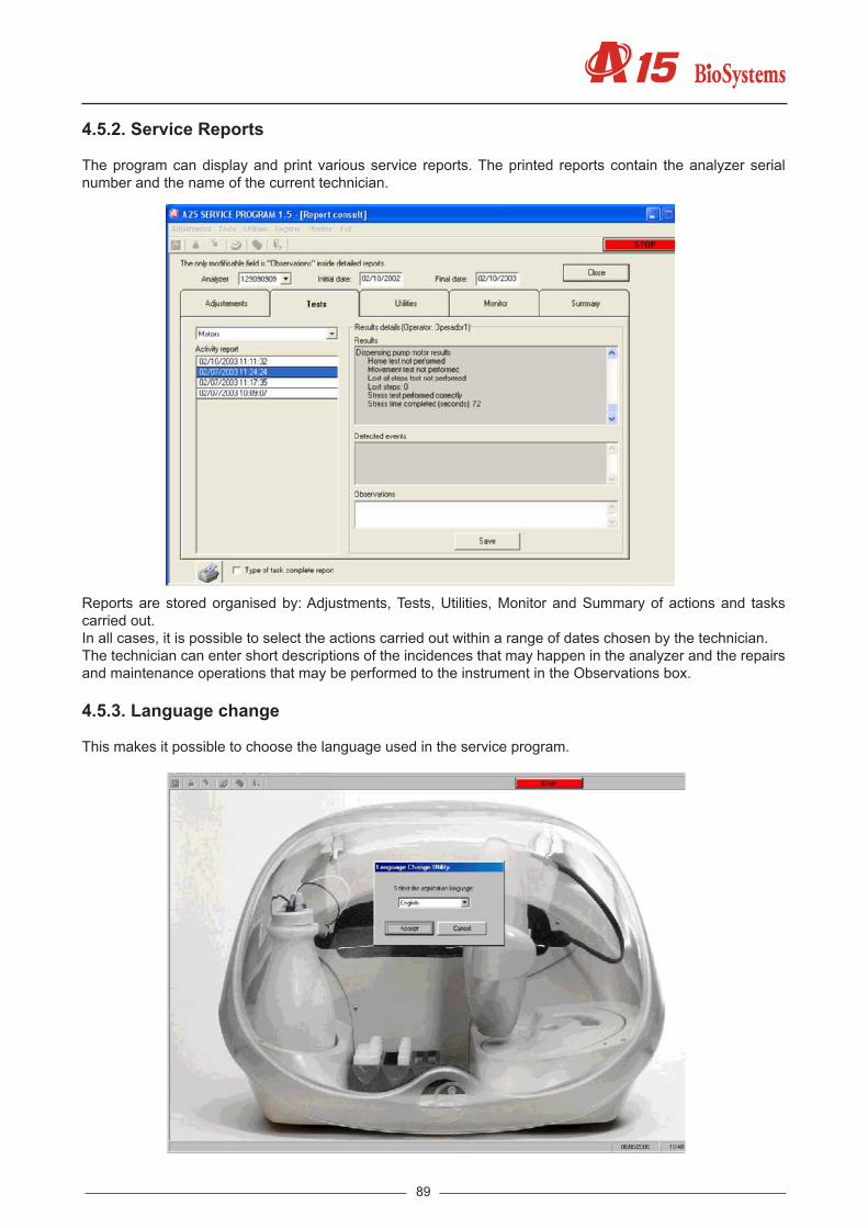
89
4.5.2. Service Reports
The program can display and print various service reports. The printed reports contain the analyzer serial number and the name of the current technician.
Reports are stored organised by: Adjustments, Tests, Utilities, Monitor and Summary of actions and tasks carried out.In all cases, it is possible to select the actions carried out within a range of dates chosen by the technician.The technician can enter short descriptions of the incidences that may happen in the analyzer and the repairs and maintenance operations that may be performed to the instrument in the Observations box.
4.5.3. Language change
This makes it possible to choose the language used in the service program.

90
Service manual
4.5.4. Users
Two types of user can be created with different access levels:
· SAT. This user has full access to the programme. This user has permission to create and/or delete other users. · User. This user has restricted access to the programme. This user can only perform the tests and run the utilities. He/she can not make any adjustments or load any previously saved adjustments files or change the firmware version of the analyser.
From the Users menu, it is possible to create, delete and change users. The Change password option is for each user to change his own password.
4.6. MONITOR These enable the low level communication with the analyzer to load new versions of the program in the flash memory of the analyzer (firmware) or to restore the default adjustment parameters. The firmware of the analyzer resides in a permanent flash memory. The change of this program can be made through the computer without the need for changing the memory chip. Once the program has changed, the analyzer is restarted with the new version of the program. While the copy process is being performed, the screen indicates the percentage completed. To load the new version, press the Start button, previously indicating where the program is located using the Open button. First of all, the current content of the flash memory is deleted and then the new program is loaded. This operation may take several minutes.There is also the option to Restore Default Adjustments, selecting the option and pressing Start.If the technician wants the analyzer to enter monitor mode (e.g. because the analyzer does not respond be-cause the firmware was incorrectly loaded, he may do so by shutting down the analyzer, pressing the Force Monitor button and then rebooting.Once the new programme has been loaded or the default adjustments have been restored, exit the monitor by pressing the Close button.

91
4.7 User’s program In this section, the service options in the user program will be described. These options are intended to confi-gure the user’s access level. Each section explains how to manage and create different levels of access to the user program of the analyser. When the program is installed for the first time, there is not a created user and access to the program is complete.
4.7.1 Configuration of the level of access to the analyser
To activate the option of level of access to the analyser, the first time you should enter as administrator, whose values are:
Name of user: admin access key: A15
with this screen, the application with the operation by passwords is configured. The first time that the program is activated, it forces the user to change the initial password. It is possible to create three types of user with different access levels:
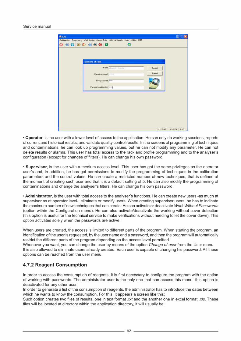
92
Service manual
• Operator, is the user with a lower level of access to the application. He can only do working sessions, reports of current and historical results, and validate quality control results. In the screens of programming of techniques and contaminations, he can look up programming values, but he can not modify any parameter. He can not delete results or alarms. This user has total access to the rack and profile programming and to the analyser’s configuration (except for changes of filters). He can change his own password.
• Supervisor, is the user with a medium access level. This user has got the same privileges as the operator user’s and, in addition, he has got permissions to modify the programming of techniques in the calibration parameters and the control values. He can create a restricted number of new techniques, that is defined at the moment of creating such user and that it is a default setting of 5. He can also modify the programming of contaminations and change the analyser’s filters. He can change his own password.
• Administrator, is the user with total access to the analyser’s functions. He can create new users -as much at supervisor as at operator level-, eliminate or modify users. When creating supervisor users, he has to indicate the maximum number of new techniques that can create. He can activate or deactivate Work Without Passwords (option within the Configuration menu). He can also activate/deactivate the working without cover detection (this option is useful for the technical service to make verifications without needing to let the cover down). This option activates solely when the passwords are active.
When users are created, the access is limited to different parts of the program. When starting the program, an identification of the user is requested, by the user name and a password, and then the program will automatically restrict the different parts of the program depending on the access level permitted. Whenever you want, you can change the user by means of the option Change of user from the User menu.It is also allowed to eliminate users already created. Each user is capable of changing his password. All these options can be reached from the user menu.
4.7.2 Reagent Consumption
In order to access the consumption of reagents, it is first necessary to configure the program with the option of working with passwords. The administrator user is the only one that can access this menu -this option is deactivated for any other user. In order to generate a list of the consumption of reagents, the administrator has to introduce the dates between which he wants to know the consumption. For this, it appears a screen like this:Such option creates two files of results, one in text format .txt and the another one in excel format .xls. These files will be located at directory within the application directory, it will usually be:

93
c:\Program Files\A15\Reagents
and the contents of the file shows similar this:
REAGENT CONTROL CONSUME REPORT
Initial Date: 02/11/2004 Final Date: 02/12/2004 Test Blank Prep. Calibrator Pre Control Prep. Patient Prep. Total Prep. Vol. R1 (uL) Vol. R2 (uL) glucose 1 0 0 5 6 1332 0alt 1 0 0 3 4 888 0bilirrubin 9 0 0 23 32 7104 3552Re-agents

Service manual
94
5. MAINTENANCE AND CLEANINGFirst of all, this chapter gives a step-by-step description of the different operations required for both the preventive maintenance and repair of the analyzer. The following are basic recommendations for the preventive maintenance of the instrument. Finally, a series of instructions for care and cleaning are given.
5.1. MAINTENANCE OPERATIONS5.1.1. Housings and covers
5.1.1.1. Removing the needle unit casing
The needle unit has two casings fixed with four screws eacha) First remove the dispensing needleb) Remove the screws that hold the casings in position.c) Remove the upper casing by lifting upwards.d) Remove the lower casing by pulling downwards.
5.1.1.2. Removing the front housing
a) Remove the grommets on either side of the casing. Pull on the grommets, not on the hoses.b) Remove the screws that hold the casing in position from the front.c) Move the needle unit to its forward centre position.d) Remove the casing by pulling it upwards and to the front.

95
5.1.1.3. Removing the main cover
a) Open the analyzer cover.b) Remove the two bottom screws that hold the cover to each hinge.c) Pull the cover upwards.

Service manual
96
5.1.1.4. Removing the upper casing
a) Remove the front housing.b) Remove the main cover.c) Remove the screws as shown in the following figures.d) Remove the casing by pulling it upwards.

97

Service manual
98
5.1.1.5. Removing the spring protector
a) Remove the three screws at the rearb) Pull the protector upwards.
5.1.2. Operating arm
5.1.2.1. Fully removing the operating arm
a) Remove all the analyzer housing.
45

99
b) Disconnect the connector (1) that goes to the board that goes to the needle unit and cut all the flanges required.c) Disconnect the Teflon dispensing pipe (2).d) Remove the cover that covers the X carriage interconnection board (3). Cut the flanges that hold the flat bands
and disconnect them from the board. e) Unscrew the four studs that fasten the two X guide axes and which are located on the arm supports.f) Pull the two guide axes as shown in the figure.
5.1.2.2. Changing the arm hose
a) Remove all the analyzer housing.b) Disconnect the connector (1) that goes to the board that goes to the needle unit and cut all the flanges required.c) Disconnect the Teflon pipe at both ends (needle and electrovalve) (2). Cut all the flanges that guide the pipe to the
electrovalve.d) Remove the cover (3). To do so, open the electronics box at the rear and remove the fastening clips. Disconnect
the connector that goes to the CPU board and the earth connection (6).e) Unscrew the flange screw (4).f) Replace the hose, connect and replace the flanges.
1 34
2
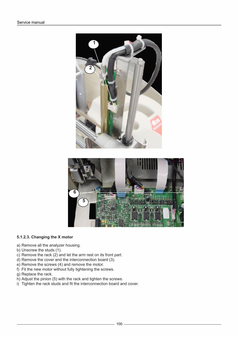
Service manual
100
5.1.2.3. Changing the X motor
a) Remove all the analyzer housing.b) Unscrew the studs (1).c) Remove the rack (2) and let the arm rest on its front part.d) Remove the cover and the interconnection board (3).e) Remove the screws (4) and remove the motor.f) Fit the new motor without fully tightening the screws.g) Replace the rack.h) Adjust the pinion (5) with the rack and tighten the screws.i) Tighten the rack studs and fit the interconnection board and cover.
5
6
1
2

101
1
2
5
3
4

Service manual
102
5.1.2.4. Changing the Y motor
a) Remove all the casings from the analyser except for that of the needle unit.b) Connect the motor cable (1).c) Remove the motor by removing the screws (2).d) Change the motor (with pulley).e) Remove the fastening plate (3).f) Fit the fastening plate on the new motor.g) Fit the motor without tightening the screws.h) Connect the notched belt (4) , tighten it manually displacing the motor and tighten the 4 screws that hold it in po-
sition.i) Connect the motor cable.
5.1.2.5. Changing the Z motor
a) Remove the X motor as explained in the section titled Changing the X motor.b) Unscrew the two studs (1).c) Remove the four screws that hold the motor in position (2).c) Remove the connector and remove the motor by pulling it towards the rear.
1
2
4
3
1
2
3
4
5

103
d) Remove the motor axle by unscrewing the stud.e) Fit the axle to the new motor.f) Refit the motor but without tightening the studs (1).g) Fit the X motor and the interconnection board (3).h) Adjust the axis (4) so that the encoder is centred on the photosensor (5) and tighten the studs (1).
5.1.2.6. Changing the Y motor belt
a) Loosen the Y motor (see section).b) Remove the pulley (1) by extracting the bolt (2) and the nut (3).c) Loosen the clamp that fastens the belt to the needle unit.d) Change the belt for a new one.e) Refit the pulley (1).f) Put the belt on the pulleys, tighten it manually, displacing the motor and fasten it by tightening the 4 screws.
5.1.2.7. Changing the spring
a) Remove the pulley (1) as indicated in the section titled Changing the Y motor belt.b) Unscrew the bolts (2).c) Remove the bolts (3).c) Remove the spring unit (4).d) Refit the new unit but without tightening the studs (2). Make sure that the Y carriage axes are perfectly aligned.e) Refit the pulley (1) as indicated in the section titled Changing the Y motor belt.
Tightening the spring:f) During the following operations, keep the needle unit in its top position.g) Use a spanner to turn the pulley (5) anticlockwise. Complete 3 to 4 turns.h) Tighten the bolts (2) making them coincide with the flat part of the axle (6).
1
2
3

Service manual
104
5.1.3. Dispensing system
5.1.3.1. Changing the thermostated pipe.
a) Remove the arm casing.b) It is recommendable to remove the needle before handling the unit to prevent it from being damaged.c) Disconnect the electrical connector (1) and the Teflon pipe (2) and remove the flanges (3).d) Remove the protective cover (4).e) Remove the entire thermostated pipe by removing the 3 screws (5) that hold it in place.f) Refit the new unit, replacing the flanges.
1
1
3
4
5
6

105
1 2 3
4
5
1
2
3
5.1.3.2. Changing the dispensing pump seal
a) Remove the fluidic chamber (1).b) Remove the washer (2).c) Replace the seal (3).d) Refit the washer (2).d) Refit the fluidic chamber on the pump by tightening the four screws gradually.

Service manual
106
5.1.3.3. Changing the dispensing pump motor
a) Remove the dispensing pump by first of all unscrewing the nuts (1) and then the bolts (2) from the base.b) Remove the motor by removing the screws (3). c) Unscrew the body (4). d) Loosen the Allen bolt and remove the endless screw and the axial bearing (5). e) Fit the axial bearing and the endless screw on the new motor. The Allen bolt must coincide with the machined
surface of the motor axle. Put screwfastener on the bolt. It is very important to remove the axial space between the motor, the bearing and the endless screw. To avoid the displacement of the motor axle, use the MO0009 tool. Tighten the Allen bolt.
g) Clean off the used grease. Put new grease on the endless screw and on the piston support. h) Clean the piston if it has been stained with lubricant grease.i) Fit the motor with the endless screw and the piston support on the body of the pump, making the support guide
coincide with the lock nut (6). j) Fit the pump to the base. The bolts (2) should not apply pressure to the body (4). Tighten the nuts (2).
3
4
5
6
1
2

107
5.1.3.4. Changing the dispensing electrovalve
a) Disconnect the connectors (1) and the electrical connector.b) Remove the screws (2) that hold the electrovalve in position. c) Fit the new electrovalve. Do not tighten the screws to excess so as not to deform the plastic body of the electrovalve
and damage its leakproof quality. d) When refitting the connectors, use a spanner to tighten them 1/4 of a turn to make sure they are watertight.
5.1.3.5. Changing the container tube unit
a) Remove the front housing.b) Disconnect the nuts and the tubes. Remove the grommet from the back housing.c) Fit the new unit.
5.1.3.6. Changing the distilled water container filters
a) Unscrew the lid and remove the tubes from the distilled water container.b) Remove the Teflon tube filter by unscrewing the nut.c) Remove the PVC tube filter by pulling on the filter.d) Fit the new filters and replace the tubes in the container.
2
1

Service manual
108
5.1.4. Reactions rotor and reading
5.1.4.1. Changing the rotor temperature probe
a) Remove the upper casing.b) Disconnect the electrical hose from the interconnection board.c) Remove the thermal insulation from the temperature probe.d) Unscrew the probe (2). e) Clean the thermal silicone form the housing and put fresh thermal silicone on the end of the new probe.f) Fit the new probe.
1
2

109
12
5.1.4.2. Fully removing the rotor
a) Remove the upper casing.b) Disconnect the electrical hoses and the lampholder (1). c) remove the rotor from the base by removing the 3 leg screws.
5.1.4.3. Changing the rotor Peltier cells
a) Remove the complete rotor.b) Remove the bolt (1) and the insulation (2) and the temperature probe (3).b) Remove the fan (4) and the corresponding radiator (5).c) Unsolder the Peltier to be replaced and solder the new one in its place. Exactly reproduce the original cabling.d) Clean the thermal silicone from the heating canal and from the radiator with alcohol. Put fresh thermal silicone on
both sides of the new Peltier. Tighten the two bolts equally and apply bolt-fastener.e) Refit the system.

Service manual
110
5.1.4.4. Changing the rotor cover detector
a) Remove the rotor completely and remove the insulation.b) Unscrew the stud (1) and remove the sensor (2).c) Unsolder the sensor and then solder again.d) Refit the sensor.
5.1.4.5. Changing the rotor start photosensor
a) Remove the rotor completely and remove the insulation.b) Remove the start photosensor board (1). Unsolder this board from the electrical hose and solder the new one.c) Refit the system and check that the centring unit turns freely.
1
2
3
4
5

111
1
2
1
5.1.4.6. Changing the rotor motor
a) Remove the rotor completely. Remove the insulation.b) Remove the rotor covers.c) Remove the nuts (1).d) Remove the motor from below. Disconnect the hose.e) Fit the new motor on the unit.f) Perform the miss test on the rotor motor and the rotor positioning test in the service program to check that the gap
between gears is correct and that the system functions correctly.

Service manual
112
5.1.4.8. Changing the lamp
The analyzer is fitted with a 6 V 10 W halogen lamp with an estimated average lifetime of 2,000 hours. It is recom-mended that you change the lamp every year even though its lifetime has not run out. When the lamp needs to be changed, access the Change lamp utility of the user programme and follow the steps indicated by the programme itself. To replace the lamp, proceed as follows:a) Remove the rotor cover.b) Loosen the bolt (1) that holds the fastening tab of the lamp holder in position.c) Push the tab back.d) Remove the lamp holder, loosen the Allen screw and take out the lamp.e) Insert the new lamp, pushing the terminals to the back. Tighten the Allen screw until the lamp is securely in place.
Do not touch the lamp bulb with your fingers. To handle the lamp, use the wrapping, cutting it at the terminal end and squeezing it until they come out.
f) Put the lamp holder back in place. Put the tab in position and fasten the bolt (1). Put the rotor cover back.ig) The lamp does not require any adjustment, but it can be placed in the analyzer in two possible positions by turning
1
1

113
it 180º around its longitudinal axis. The programme itself requires the user to place the lamp in the two possible positions and check in which of the two maximum light intensity is obtained in the optical system.
5.1.4.9. Changing an optical filter
a) Access the Filter Wheel Configuration screen of the user or service programme. Indicate which filter is to be chan-ged (position 1-9) and click on the Change filter button.
b) Remove the rotor cover.c) Remove the filter wheel cover by simply pulling on it.d) Remove the top filter using a pair of fine pliers.e) Position the new filter by pressing down until it is correctly in place.f) Do not leave the position free without putting a filter holder in place. If no filter is required in this position, put a
covered filter holder in place. g) Refit the filter wheel cover. Put the rotor cover back.h) If it is different, introduce the wavelength of the new filter that has been installed.
5.1.4.10. Configuration of the filter wheel
a) Remove the rotor completely. Remove the insulation.b) Remove the cover (1).c) Loosen the Allen bolt that holds the filter wheel in place (2).d) Remove the motor (3). On removing the motor, joined to the wheel axle, the wheel comes free. e) Place the new filter wheel in position and introduce the motor with the axle in position. The Allen bolt must coincide
with the machined area of the axle. Put screwfastener on the bolt.f) Fit the wheel to the axle. Check that the rotor turns freely without mechanical interference.
5.1.4.11. Changing the filter wheel start photosensor
See the figure in the previous section.
a) Remove the complete rotor.b) Remove the cover (1).d) Remove the start photosensor board (3). Unsolder this board from the electrical hose and solder the new one.e) Refit the system and check that the wheel turns freely.
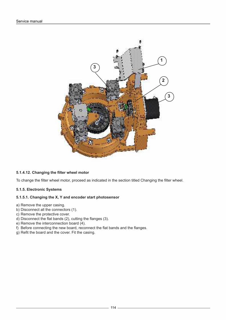
Service manual
114
5.1.4.12. Changing the filter wheel motor
To change the filter wheel motor, proceed as indicated in the section titled Changing the filter wheel.
5.1.5. Electronic Systems
5.1.5.1. Changing the X, Y and encoder start photosensor
a) Remove the upper casing.b) Disconnect all the connectors (1).c) Remove the protective cover.d) Disconnect the flat bands (2), cutting the flanges (3).e) Remove the interconnection board (4).f) Before connecting the new board, reconnect the flat bands and the flanges.g) Refit the board and the cover. Fit the casing.
2
3
13

115
1
2
3
5.1.5.2. Changing the microprocessor board
a) Fold down the back cover of the electronics.b) Disconnect all the hoses from the board.c) Remove the bolts (1).d) When installing the new board, reconnect all the connectors carefully.
5.1.5.3. Changing the power supply board
a) Fold down the back cover of the electronics.b) Disconnect all the connectors from the power supply board.c) Remove the 4 screws (1) that hold the board to the base.d) Remove the board.e) When installing the new board, reconnect all the connectors carefully.

Service manual
116
5.1.5.4. Changing the main power supply source
a) Fold down the back cover of the electronics.b) Remove the input and output connectors by unscrewing the bolts (1).c) Remove the 3 bolts (2) that hold the source in position.d) Remove the source.
5.1.5.5. Changing the photometric system board
1
1
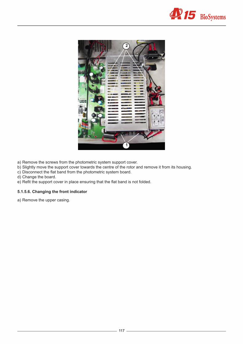
117
1
2
a) Remove the screws from the photometric system support cover.b) Slightly move the support cover towards the centre of the rotor and remove it from its housing.c) Disconnect the flat band from the photometric system board.d) Change the board. e) Refit the support cover in place ensuring that the flat band is not folded.
5.1.5.6. Changing the front indicator
a) Remove the upper casing.

Service manual
118
b) Disconnect the hose from the rotor interconnection board. c) Pull the fastening ring (1) down.d) Pull the LED (2) up to remove it.
5.1.5.7. Changing the firmware program
The firmware of the analyzer resides in a permanent flash memory. The change of this program can be made through
the computer without the need for changing the memory chip. For this, follow the instructions in the section Loading new firmware versions of the Service Program.
5.2. RECOMMENDED PREVENTIVE MAINTENANCE
1
2

119
It is recommended that the following maintenance actions are performed annually or every 2,000 working hours.
Operating arm1. Check the state and tension of the belt.2. Replace the elements in an unsatisfactory state.3. Make the adjustments and tests related to the service program.
Dispensing system.1. Exhaustively wash all the dispensing circuit with washing solution and rinse it with distilled water.2. Remove and clean the needle. Check its state.3. Check the state of all the dispensing circuit tubes. Check the absence of obstructions or diameter changes.4. Check the leakproof quality of the nuts and the 3-channel electrovalve body.5. Check the leakproof quality of the dispensing pump nut and seal. Check there is no loss and no bubbles. Change
the seal every 2 years.6. Clean the distilled water container filters.7. Clean the washing station.8. Check the state of the washing system tubes.9. Replace the elements in an unsatisfactory state.10. Make the adjustments and tests related to the service program.
Reactions rotor1. Check the state of the heating canal.2. Verify the gap betwen gears.3. Replace the elements in an unsatisfactory state.4. Make the adjustments and tests related to the service program.
Optical system1. Check the state of the lamp. Check if it has been working for over 1,000 hours.2. Clean the filters.3. Clean the photodiode.4. Replace the elements in an unsatisfactory state.5. Make the adjustments and tests related to the service program.
5.3. CARE AND CLEANING
5.3.1. General care of the analyzer
a) Never use detergents or abrasive products for cleaning the surface of the analyzer. Use only a damp cloth with water and pH-neutral soap.
b) If a reagent or corrosive product spills or splashes onto the apparatus, clean it with a damp cloth and soap imme-diately. If necessary, protect your hands with appropriate laboratory gloves.
c) All the elements of the analyzer have drainage conduits leading to the exterior to enable the elimination of any liquid spilled and to prevent the apparatus from flooding. If the spillage is significant, the liquid spilled onto the table through the drainage conduits and the analyzer must be adequately cleaned.
d) When not in use, close the main cover of the analyzer to protect it from dust.5.3.2. Cleaning the optical system
The components of the optical system must be cleaned periodically in order to keep them free from dust and dirt. These components are the lamp, the filters and the photodiode. The recommended necessary material is as follows: - Special paper for cleaning optical components (non-abrasive paper which does not leave solid residue).- Ether and alcohol solution at 50%- Cotton wool buds.- Small bellows.All the optical elements must be handled in an area of maximum cleanliness, given that they are fragile and delicate.

Service manual
120
To remove them and refit them, the corresponding instructions given in the Maintenance chapter must be carefully followed. Avoid touching the useful area of these elements with fingers. The filters and the photodiode must be held by the sides. Do not touch the lamp bulb. To handle the lamp, use the wrapping, cutting it at the terminal end and squeezing it until they come out. To clean the optical components, bear in mind the following:a) Remove the dust on the surface of the component with the bellows. This will avoid scratching by particles when
cleaning with paper.b) Carefully clean the surface of the component with the cleaning paper.c) If the dirt is persistent or greasy, clean the component with the paper moistened with the alcohol and ether solution.
Then dry with dry paper. To clean the filters or the window of the photodiode, use the cotton wool buds with the paper in difficult and delicate areas.
d) Finally, it is recommended that you use the bellows once again, thus removing any remains of paper or cotton.
5.3.3. Cleaning the dispensing system
It is a good idea to recommend to the user that he configures the analyzer to automatically wash the dispensing system with washing solution at the start and end of each working day to ensure that it is completely free from air bubbles and is perfectly clean. With the initial wash, the system is ready for working in optimum conditions during the entire working day, offering maximum performance. With the final wash, the analyzer cleans the needle at the end of the working day, keeping it in optimum condition for future working days. Additional washing of the dispensing system can be performed using the Dispensing system wash utility of the user program. The analyzer must be in standby mode.
The user himself should clean and check the state of the distilled water container filters at least once every 3 months. The service operations should also check the state of these filters.
If the needle is obstructed by solid residue, it must be removed and cleaned using the metal cleaning rod supplied with the analyzer. For this, the Remove the dispensing needle utility should be used. It is also recommendable to clean the outside surface of the needle with a piece of cotton or a soft cloth dampened with alcohol. The needle must be replaced if it noticeably deteriorates.
5.3.4. General cleaning of the interior of the apparatus
It is important for the interior of the instrument to be free from dust at all times in order to preserve the correct functio-ning of the different elements. For this, remove the front housing of the analyzer and electronics cover and carefully clean the dust inside the instrument.

121
A I. TECHNICAL SPECIFICATIONSPLEASE NOTE
The manufacturer accepts no liability for damage caused by incorrect use of the apparatus.
GENERAL SPECIFICATIONS
Automatic random and continual access analyzer aimed at giving results per patient, with direct photometric reading over a reactions rotor.
Preparation cycle time 24 s (up to 150 prep/h)Warm-up time 25 minsReading time for each preparation Every 24 s, up to 10 minsDimensions 840 x 670 x 615 mm (33.1”x26.8”x24.2”)
(length x depth x height)Weight 45 kg (100lb) REAGENTS AND SAMPLES TRAY
Positions for racks 4Capacity of the sample racks 24Maximum number of samples 72ø13 mm, ø15 mm sample tubes (max. height 100 mm), ø13 mm paediatric wellCapacity of the reagent racks 10Maximum number of reagents 3020 ml and 50 ml reagent bottlesPossible configurations
Sample racks Reagent racks Number of samples Number of reagents 1 3 24 30 2 2 48 20 3 1 72 10
DISPENSING SYSTEM
NEEDLE
Detachable tipVertical length 110 mmCapacity level detectionSelf-adjustment of position
NEEDLE THERMOSTATATION SYSTEM
Actuator Resistive elementsControl PIDThermostatation time < 15 sDispensation temperature 37°CTrueness ± 0.5°CRepeatability ± 0.5°C

Service manual
122
DISPENSING PUMP
Ceramic piston with PTFE-graphite sealPiston diameter 8 mmDisplacement 25 mmDispensing volume 3 µL - 1250 µLResolution 0.126 µLFuzziness <1% up to 3 µLDispensing speed max. 880 µL/sProgrammable reagent volume 10 µL -440 µLProgrammable sample volume 3 µL - 40 µL
NEEDLE WASHING SYSTEM
System liquid consumption approx. 2.4 ml per preparationSystem liquid container volume 3000 mlWaste container volume 3000 mlCapacitance waste and water level control
REACTIONS ROTOR AND READING
WELL ROTOR
Semi-disposable extractable methacrylate rotorNumber of wells 120Accepted reaction volumes 200 µL - 800 µL Light path length 6 mm
ROTOR THERMOSTATATION SYSTEM
Actuators 4 Peltier cellsControl PIDWorking temperature 37°CTrueness ± 0.2°CStability ± 0.1°C
OPTICAL SYSTEM
Halogen lamp 6 V, 10 WWavelength selection with compensated interferential filtersDetection system with silicon photodiode and 20-bit AD integrator-converterMeasurement range from -0.05 A to 2.5 AReading speed 1.25 readings/sMaximum number of filters 9Base configuration of the filter drum 340, 405, 505, 535, 560, 600, 635, 670 nmWavelength precision ± 2 nmBandwidth 10 ± 2 nmDigital resolution < 0.0001 ABase line stability max. 0.004 A in 30 mins, at 505 nmRepeatability of the reading system ± 0.0005 A to 0.1 A (CV = 0.5%)(1 SD, 505 nm, with filter movement) ± 0.0003 A to 1.0 A (CV = 0.3 %) ± 0.0005 A to 2.5 A (CV = 0.2 %)Optical repeatability between wells ± 0.003 A at 340 nm ± 0.002 A to 505 nm, 670 nm Precision ± 0.005 A to 0.1 A (± 5%) ± 0.015 A to 0.5 A (± 3%) ± 0.02 A to 1.0 A (± 2%) ± 0.04 A to 2.0 A (± 2%) ± 0.05 A to 2.5 A (± 5%) at 340 nm, 405 nm, 505 nm

123
MINIMUM COMPUTER REQUIREMENTS
Pentium IV processor or higherWindows 98 or higher256 Mb RAM50 Mb free hard disk spaceCD-ROMVGA Monitor, minimum resolution of 640x480MouseRS-232 serial channel or USB connectorThe insulation level of the communications channel of the A15 analyzer is reinforced (the insulation of the communi-cations channel of the computer must also be reinforced)(1)
POWER REQUIREMENTS
Input voltage 125-230 Vac, 50/60 HzPower 150 VAElectrical installation category (overvoltage category) IIThe power point must be officially approved, earthed and the cable must have a minimum cross-section of 1.5 mm2.
ATMOSPHERIC CONDITIONS
Interior useHeight < 2500 m Temperature 10°C - 35°C Relative humidity < 75%Contamination level 2
(1) Reinforced insulation is that which ensures protection equal to or higher than double that provided by the main insulation. The main insulation is that whose failure could lead to a risk of electric shock (EN 61010-1).
COMPLIANCE WITH DIRECTIVES AND APPLIED STANDARDS
Directive 98/79/CEE regarding sanitary products for in vitro diagnostic use• EN 61010-2 -10:2002 “Safety requirements for electrical equipment for measurement, control and laboratory use.
: EN61010-2-101:2004»Particular requirements for vitro diagnostics(IVD) medical equipment”• UNE EN 61326:1999+A1:2000+A2:2003+A3:2005+ERR:2002 “Electromagnetic equipment for measurement,
control and laboratory use –ECM requirements. • UNE-EN 55022:2000+A1:2002+CORR:2002- Radiated emissions class B-continuous interference class B”. • UNE -EN 61000-3-2:2002 «Harmonic current» • UNE -EN 61000-3-3:1997+Corr:1999+A1:2002-»Flickers» • UNE -EN 61000-4-2:1997+A1:1999+A2:2001 • UNE -EN 61000-4-3:2003+A1:2004-»Radiated immunity» • UNE -EN 61000-4-4:1997+A1:2001+A2:2002-»Fast transient /Burst» • UNE -EN 61000-4-5:1997+A1:2001-»Surge transients» • UNE -EN 61000-4-6:1998+A1:2001-»Conducted immunity» • UNE -EN 61000-4-11:1997+A1:2001-»Voltage disp short interruptions and voltage variations immunity»• UNE EN 22233-02. Test packaging.• UNE EN 24180-2.Complete and full shipment packaging.• UNE EN 22247-03(ISO 2247-2000). Fixed low frequency vibration test.• UNE EN 22248-94. Freefall vertical shock test.

Service manual
124
MAXIMUM SIZE OF ANALYZER
With the lid closed: Width: 840 mm. Depth: 670 mm. Height: 615 mm.With the lid open: Width: 840 mm. Depth: 670 mm. Height: 1,025 mm.
The manufacturer reserves the right to modify any technical specification without prior notice.

125
A II. ADJUSTMENT MARGINS TABLESMain voltage measurement pointsCIIM0015 Power supply board TP1 - 6V [5.6-5.8] V TP2 - 12V [11.7 -11.9] V TP3 - 5V [4.9-5.2] V Sp150 [23.5-24.5] V
CIIM0026 Microprocessor board TP60 - Vref motor Z [13 -15] mV TP61 - Vref motor Y [13 -15] mV TP56 - Vref motor X [13 -15] mV TP57 - Vref pump motor [13 -15] mV TP58 - Vref filter motor [13 -15] mV TP59 - Vref rotor motor [13 -15] mV
Main adjustment values of the analyzer TolerancesOperating arm positioning X axis loss of steps Loss of steps [-3,3]Y axis loss of steps Loss of steps [-3,3] Z axis loss of steps Loss of steps [-3,3] Loss of steps rotor motor Loss of steps [-3,3] Loss of steps filter drum motor Loss of steps [-3,3] Loss of steps pump motor Loss of steps [-4,4] XY position adjustment X origin [10,125] Y origin [240,290] X racks tray [620,750] Y racks tray [-20,20] X washing station [330,450] Y washing station [70,120] X rotor [60,170] Y rotor [1030,1060] Maximum Z [1090,1155]Self-centering of needle X Offset [-4,4] Y Offset [-4,4]Bottle level control sensitivity Water empty [200,255] Water full [140,230] Water calculated [170,240] Waste empty [200,255] Waste full [170,245] Waste calculated [200,245]
Level detection sensitivity Paediatric rack [45,90] 13/15mm tube sample rack [45,90] Reagent rack [25,45]Positioning of the dispensing point Dispensing rotor [90,120] Fine rotor X [35,200] Positioning of rotor in optic Positioning [-15,0] Needle thermostatation Set point temperature [35,45] Rotor thermostatation Set point temperature [36,37.5]Filter wheel positioning Positioning [-5,5]Integration times F1 340 nm [190,350] F2 405 nm [40,130] F3 505 nm [40,130] F4 535 nm [40,130] F5 560 nm [40,130] F6 600 nm [40,130] F7 635 nm [40,130] F8 670 nm [50,130] Number of counts F1 340 nm [750000,960000] F2 405 nm [840000,940000] F3 505 nm [840000,940000] F8 670 nm [840000,940000]Darkness counts F1 340 nm [3700,4300] F2 405 nm [3700,4300] F3 505 nm [3700,4300] F8 670 nm [3700,4300]SMF repeatability (Noise) Dev. Est. NC. F0 Covered ≤ 55 Dev. Est. Abs. F1 340 nm ≤ 0.0004 Dev. Est. Abs. F2 405 nm ≤ 0.0006 Dev. Est. Abs. F3 505 nm ≤ 0.0004 Dev. Est. Abs. F8 670 nm ≤ 0.0007Stability at 505 nm Dev. Est. Abs. F3 505 nm ≤ 0.0008 Max. NC [840000,940000] Min. NC [840000,940000] Max NC / Min NC ≤ 1,006Repeatability MF (Repeatability) Dev. Est. Abs. F1 340 nm ≤ 0.0008 Dev. Est. Abs. F2 405 nm ≤ 0.0006 Dev. Est. Abs. F3 505 nm ≤ 0.0005 Dev. Est. Abs. F4 535 nm ≤ 0.0005 Dev. Est. Abs. F5 560 nm ≤ 0.0005 Dev. Est. Abs. F6 600 nm ≤ 0.0005 Dev. Est. Abs. F7 635 nm ≤ 0.0005 Dev. Est. Abs. F8 670 nm ≤ 0.0005

Service manual
126
CODE DESCRIPTION (Ordered by description)AC12223 2 mm Allen keyBO11494 20 ml bottle with top (10 units)FI11563 340 nm filter unitFI11564 405 nm filter unitBO11493 50 ml bottle with top (10 units)FI11565 505 nm filter unitFI11490 535 nm filter unitFI11491 560 nm filter unitLA13195 6 V/10 W halogen lampFI11566 600 nm filter unitFI11567 635 nm filter unitFI11568 670 nm filter unitCA10456 American network cableBO11524 Bottle of concentrated system liquid (1L)BO13146 Concentrated washing solution (100mL)FI11498 Covered filter unitAC13193 Detachable needleCA10455 European network cableAC13200 Filter drum coverAC13199 Height-adjustable legZO13196 Lamp holder fastening systemAC12222 Metal rod for cleaning the needleAC13198 Operating arm fastening for transport
(screw and foam)AC11485 Reaction rotor (10 units)AC13197 Reactions rotor coverAC11486 Reactions rotor fastening screwAC10770 Sample wells (1000), Paediatric reaction
wellsFI10466 Serial channel cable for connection to PCFU13194 Set of 2 A (F) fusesFI13190 System liquid container filtersBO13189 System liquid container with topAC14549 Reagent rackAC14554 Tubes adapter (80 units)AC14550 Tube rackAC13188 User programme CDBO13191 Washing solution container with topBO13192 Waste container with lid and fitting
A III. LIST OF CONSUMABLES, ACCESSORIES AND SPARES If any of the components of the analyzer deteriorate of if any of the perishable materials are required, always use original BioSystems material. The following table shows lists of components that may be required. To purchase said components, please contact your usual distributor and order each element using its corresponding code. This will simplify work and minimise errors.
CODE DESCRIPTION (Ordered by code)CA10455 European network cableCA10456 American network cableFI10466 Serial channel cable for connection to PCAC10770 Sample wells (1000),Paediatric reaction
wellsAC11485 Reaction rotor (10 units)AC11486 Reactions rotor fastening screwFI11490 535 nm filter unitFI11491 560 nm filter unitBO1149 350 ml bottle with top (10 units)BO1149 420 ml bottle with top (10 units)FI11498 Covered filter unitBO11524 Bottle of concentrated system liquid (1L)FI11563 340 nm filter unitFI11564 405 nm filter unitFI11565 505 nm filter unitFI11566 600 nm filter unitFI11567 635 nm filter unitFI11568 670 nm filter unitAC12222 Metal rod for cleaning the needleAC12223 2 mm Allen keyBO13146 Concentrated washing solution (100mL)AC13188 User programme CDBO13189 System liquid container with topFI13190 System liquid container filtersBO13191 Washing solution container with topBO13192 Waste container with lid and fittingAC13193 Detachable needleFU13194 Set of 2 A (F) fusesLA13195 6 V/10 W halogen lampZO13196 Lamp holder fastening systemAC13197 Reactions rotor coverAC13198 Operating arm fastening for transport
(screw and foam)AC13199 Height-adjustable legAC13200 Filter wheel coverAC14549 Reagent rackAC14550 Tube rackAC14554 Tubes adapter (80 units)
List of user spares, perishable materials and accessories.

127
CODE DESCRIPTION (Ordered by description)MO13358 A15 fanAC13365 Arm hoseCA13393 Base coverCA13379 Bottom cover of needle setPC13384 Communications boardTU13366 Container tube unitAC13362 Dispensing pump fluid chamberMO13363 Dispensing pump motorAC13361 Dispensing pump sealME13364 ElectrovalveAC13375 Filter wheel bodyMO13376 Filter wheel motorPC13382 Front indicatorCA13395 Front al coverAC13356 Full thermostated needle setME13359 Full dispensing pumpAC13350 Full operating armAC13370 Full reactions rotorZO10407 Fuse holderME13377 Hydro-pneumatic cylinder of the cover
hingeCA13397 Instrument coverZO13374 Lamp holderTR13389 Main power supplyVA10355 Mains connectorIN11557 Mains switch PC13380 Microprocessor boardMO13357 Peltier fanCE13388 Peltier cellPC13381 Photometric system boardPC13383 Power supply boardPC13387 Pumps interconnection boardTU13368 PVC waste tubeAC13373 Rotor cover sensorPC13386 Rotor interconnection boardMO13372 Rotor motorAC13371 Rotor temperature sensorCA13308 CD-ROM with Service programme and
Service manualFO11570 Set of five photosensorsCA13396 Spring protection coverME13355 Spring setAC11860 Temperature adjustment toolAC13360 Thermostated needle fastening nutCA13394 Upper coverCA13378 Upper cover of needle setAC13369 Waste container nut and capME13367 Waste pumpMO13351 X guide motorPC13385 XYZ interconnection boardME13352 Y carriage beltMO13353 Y guidemotorMO13354 Z guide motor
CODE DESCRIPTION (Ordered by code)CA13308 CD-ROM with Service programme
and Service manualVA10355 Mains connectorZO10407 Fuse holderIN11557 Mains switch FO11570 Set of five photosensorsAC11860 Temperature adjustment toolAC13350 Full operating armMO13351 X guide motorME13352 Y carriage beltMO13353 Y guidemotorMO13354 Z guide motorME13355 Spring setAC13356 Full thermostated needle setMO13357 Peltier fanMO13358 A15 fanME13359 Full dispensing pumpAC13360 Thermostated needle fastening nutAC13361 Dispensing pump sealAC13362 Dispensing pump fluid chamberMO13363 Dispensing pump motorME13364 ElectrovalveAC13365 Arm hoseTU13366 Container tube unitME13367 Waste pumpTU13368 PVC waste tubeAC13369 Waste container nut and capAC13370 Full reactions rotorAC13371 Rotor temperature sensorMO13372 Rotor motorAC13373 Rotor cover sensorZO13374 Lamp holderAC13375 Filter wheel bodyMO13376 Filter wheel motorME13377 Hydro-pneumatic cylinder of the
cover hingeCA13378 Upper cover of needle setCA13379 Bottom cover of needle setPC13380 Microprocessor boardPC13381 Photometric system boardPC13382 Front indicatorPC13383 Power supply boardPC13384 Communications boardPC13385 XYZ interconnection boardPC13386 Rotor interconnection boardPC13387 Pumps interconnection boardCE13388 Peltier cellTR13389 Main power supplyCA13393 Base coverCA13394 Upper coverCA13395 Front al coverCA13396 Spring protection coverCA13397 Instrument cover
List of spares exclusive to the technical support service.

Service manual
128
A IV. LIST OF REQUIRED TOOLS1. Set of metric Allen keys.2. Loctite 243 screwfastener or similar3. Mechanical grease ELESA NT1 (for ceramic pump only) (AC13079).4. Heat silicone or similar5. Soldering iron6. Screwdrivers or two 3 mm Allen keys.7. Loctite 245 or similar (for ceramic pump only).8. Temperature adjustment tool (AC11860).9. XYZ adjustment tool (AC15000)
A V. SOFTWARE VERSIONSChange in the versions of service programDate version Change 04/04/06 3.0.1 First release version 20/07/06 3.0.2 Correction of errors Improve the checking before load a new firmware 18/12/06 3.1.0 Modify the level sensitivity adjustment screen to incorporate the in-
dependent adjustment by type of rack.Added the help menu with the preventive maintenance guide.
13/12/07 3.2.0 Improve the fine zmax adjustment. Include a new menu to change the rotor type.
22/01/09 4.0.0 Improve the adjustment position of the racks and reagents racks. 17/07/09 4.1 Modify the adjustment menu to include an option to select the type
of racks: metal rack or plastic racks. Included a new menu to use the photometry tool.
Temperature adjustment tool

129
Change in the versions of user programDate version Changes04 /04/06 3.2.1 First release version20/07/06 3.2.2 New button in the tools menu, reset the historical base
line Fix the options of the initial and final wash. Delete the menu to
choose the parameter of initial and final wash. Add a maintenance guide in the help menu.
14/11/06 3.3.0 Improve and optimitation of the execution times of the application. Corrected the application errors that showed the message «not res-pond»
05/03/07 3.3.1 Korean language included Change of some test adapters Correction of low frequency errors 21/03/07 3.3.2 Added the Korean language. Correction of Run Time errors.14/06/07 4.0.0 Added the Romanian and indonesian languages Added the substrate depletion control function in kinetic test Added the prozone control function in turbidimetric test Added the correlation of result per test with other analysers Added graphical representation of results Change the reagent Blank use in calibration factor calculation Added a new patient results report Added a new document explaining the Remarks messages 17/07/09 4.1 New function of LIMS online communication. New function of the calibration plot: when a concnetration value is out
of the plot it can repeat with a postdilution factor.
Change in the versions of firmwareDate version Change 04/04/06 2.90 First release version 09/05/06 2.92 Improvements in the generation of the pattern of encoder 18/12/06 3.10 In order to avoid the splashes in the dispensation of the predilution,
the dispensation speed have been reduced. The sensitivity adjustment have been split in 3 diferents ad-
justments, one for each type of rack. Correction of the bireagent with 10 minuts of reading time and with
programmed contamination. 6/02/07 3.12 Increase the stabilization time of the commutation of 3 way electro-
valve. 07/03/07 3.14 Correction: when shut-down is made and next the warming-up wi-
thout disconnecting the analyzer the termostatización of the probe does not activate.
15/05/07 3.20 Added an autodiagnosis system for internal use.29/10/07 3.24 Correction of the transition state from shutdown to slee-
ping. Improved the swith-off of global-stress Correction of initial washing when previously the cover was open
and close. 16/04/08 3.28 Correction of the predilution manoeuvre when tube rack is used 22/01/09 3.50 Improve the adjustment position of the racks and reagents racks.
New sensibility maps of the improved racks 17/07/09 3.61 Include both types of sensibility maps: metal maps and plastic
maps. Correction about enter the serial number of the analyzer Added a protection of the Shut-down process.

Service manual
130
Compatibilities tableUser A25 3.2.1 3.2.2 3.3.0 3.3.1 3.3.2 4.0.0 4.1firmware 2.90 x x x x x x x2.92 x x x x x x x3.10 x x x x x x x3.12 x x x x x x x3.14 x x x x x x x3.20 x x x x x x x3.24 x x x x x x x3.28 x x x x x x x3.50 x x x x x x x3.61 x x x x x x x
It is advisable to always install the last existing version of firmware.

Costa Brava, 30, 08030 Barcelona - Spain Tel: 34-93 311 00 00 Fax: 34-93 346 77 [email protected] http://www.biosystems-sa.com
BIOSYSTEMS, S.A.e-mail:biosystems