service module - spaceref · рис - figure рзм - connector СБ - solar array СМ - service...
TRANSCRIPT

SM COMMUNICATION SYSTEM 1E 25 Sep 00
Г908/00 1 17КС.403 –00Г 17КС.0000А-0ИЭ80 ч.7 кн.1 Лист
Approved per signature page
SERVICE MODULE
COMMUNICATION SYSTEM (РТК)
SM.1
2000

SM COMMUNICATION SYSTEM 2E 25 Sep 00
Г908/00 1 17КС.403 –00Г 17КС.0000А-0ИЭ80 ч.7 кн.1 Лист
Revision Log
1 25 Sep 00 4—1 25 Sep 00 2 25 Sep 00 4—2 25 Sep 00 3 25 Sep 00 5—1 25 Sep 00 4 25 Sep 00 5—2 25 Sep 00 5 25 Sep 00 5—3 25 Sep 00 6 25 Sep 00 5—4 25 Sep 00 7 25 Sep 00 5—5 25 Sep 00 8 25 Sep 00 5—6 25 Sep 00 1—1 25 Sep 00 6—1 25 Sep 00 2—1 25 Sep 00 2—2 25 Sep 00 2—3 25 Sep 00 2—4 25 Sep 00 2—5 25 Sep 00 2—6 25 Sep 00 2—7 25 Sep 00 2—8 25 Sep 00 2—9 25 Sep 00 2—10 25 Sep 00 2—11 25 Sep 00 2—12 25 Sep 00 2—13 25 Sep 00 2—14 25 Sep 00 2—15 25 Sep 00 2—16 25 Sep 00 2---17 25 Sep 00 2---18 25 Sep 00 2---19 25 Sep 00 3—1 25 Sep 00 3—2 25 Sep 00 3—3 25 Sep 00 3—4 25 Sep 00 3—5 25 Sep 00 3—6 25 Sep 00 3—7 25 Sep 00 3—8 25 Sep 00 3—9 25 Sep 00 3—10 25 Sep 00 3—11 25 Sep 00 3—12 25 Sep 00 3—13 25 Sep 00 3—14 25 Sep 00 3—15 25 Sep 00 3—16 25 Sep 00 3—17 25 Sep 00 3---18 25 Sep 00 3---19 25 Sep 00

SM COMMUNICATION SYSTEM 3E 25 Sep 00
Г908/00 1 17КС.403 –00Г 17КС.0000А-0ИЭ80 ч.7 кн.1 Лист
TABLE OF CONTENTS
INTRODUCTION ... . . . . . . . . . . . . . . . . . . . . . . . . . . . . . . . . . . . . . . . . . . . . . . . . . . . . . . . . . . . . . . . . . . . . . . . . . . . . . . . . . . . . . . . . . . 5
1. GENERAL INSTRUCTIONS ... . . . . . . . . . . . . . . . . . . . . . . . . . . . . . . . . . . . . . . . . . . . . . . . . . . . . . . . . . . . . . . . . . . 1—1 1.1. CREW RESPONSIBILITIES ...............................................................................................1—1 1.2. SAFETY PRECAUTIONS ...................................................................................................1—1
2. SM AUDIO SUBSYSTEM .... . . . . . . . . . . . . . . . . . . . . . . . . . . . . . . . . . . . . . . . . . . . . . . . . . . . . . . . . . . . . . . . . . . . . . 2—1 2.1. [СТТС] FUNCTIONAL SCHEMATIC...................................................................................2—1 2.2. [СТТС] OPERATIONAL FEATURES ..................................................................................2—2 2.3. [СТТС] INITIAL CONFIGURATION ....................................................................................2—2 2.4. INTERNAL COMMUNICATION ..........................................................................................2—3 2.5. CONTROL VIA LAPTOP.....................................................................................................2—3
2.5.1. REGUL COMM............................................................................................................2—3 2.5.2. LIRA COMM................................................................................................................2—3 2.5.3. VHF COMM.................................................................................................................2—4 2.5.4. REGUL- VHF2 DUPLEX RELAY.................................................................................2—5 2.5.5. LIRA-VHF2 DUPLEX RELAY ......................................................................................2—5 2.5.6. VHF1-VHF2 DUPLEX RELAY.....................................................................................2—6 2.5.7. EVA COMM.................................................................................................................2—7
2.6. CONTROL VIA ИНПУ.........................................................................................................2—8 2.6.1. VHF COMM.................................................................................................................2—8 2.6.2. EVA COMM.................................................................................................................2—9
2.7. INTERMODULE COMMUNICATION SETUP ...................................................................2—10 2.8. COMM FROM FGB...........................................................................................................2—10 2.9. COMM FROM DOCKED SOYUZ VIA INTERMODULE COMMUNICATION.....................2—10 2.10. PACKET COMM .............................................................................................................2—11 2.11. GNOM-S TAPE RECORDER OPERATION....................................................................2—12 2.12. [СТТС] FUNCTIONAL CHECK .......................................................................................2—14
2.12.1. SIDETONE CHECK.................................................................................................2—14 2.12.2. COMM CALL CHECK..............................................................................................2—14 2.12.3. PAGE CHECK.........................................................................................................2—14 2.12.4. ALARM ANNUNCIATION CHECK (DURING COMM PASS)...................................2—14 2.12.5. VHF RECEIVER FUNCTIONAL CHECK.................................................................2—15
2.13. OFF-NOMINAL SITUATIONS.........................................................................................2—17 2.13.1. NO COMM VIA LOW-NOISE HEADSET .................................................................2—17 2.13.2. SWITCHOVER TO BACKUP [СТТС] ......................................................................2—17
3. TELEVISION SUBSYSTEM .... . . . . . . . . . . . . . . . . . . . . . . . . . . . . . . . . . . . . . . . . . . . . . . . . . . . . . . . . . . . . . . . . . . 3—1 3.1. [ТВС] FUNCTIONAL SCHEMATIC .....................................................................................3—1 3.2. [ТВС] OPERATING MODES...............................................................................................3—2 3.3. SCHEMATIC OF PREPARATION FOR VIDEO EVENT AND VIDEO EVENT FROM SM...3—2 3.4. SCHEMATIC OF PREPARATION FOR VIDEO EVENT AND VIDEO EVENT FROM FGB.3—4 3.5. [ТВС] OPERATION FEATURES.........................................................................................3—5
3.5.1. TV DEACTIVATION PROCEDURE FEATURES .........................................................3—5 3.5.2. FEATURES OF [ТВС] OPERATING MODE SELECTION USING COMMANDS.........3—5

SM COMMUNICATION SYSTEM 4E 25 Sep 00
Г908/00 1 17КС.403 –00Г 17КС.0000А-0ИЭ80 ч.7 кн.1 Лист
3.6. VIDEO EVENT FROM SM (DOWNLINK)............................................................................3—6 3.7. EVA VIDEO EVENTS (DOWNLINK)...................................................................................3—7 3.8. TV SIGNAL TRANSMISSION FROM EXTERNAL Т/К TO MCC (DOWNLINK)...................3—9
3.8.1. OPERATION IN ВКУ MODE .......................................................................................3—9 3.8.2. OPERATION IN TV DISPLAY MODE (DURING DYNAMIC MODES) .......................3—10 3.8.3. CAMERA CONTROL.................................................................................................3—11
3.9. TV SIGNAL RECEPTION AND TRANSMISSION FROM SOYUZ (PROGRESS) TO MCC (VIDEO RELAY)...........................................................................................3—12 3.10. TV SIGNAL RECEPTION FROM MCC (UPLINK) ...........................................................3—13 3.11. TV COMMUNICATION (TWO-WAY VIDEO)...................................................................3—13 3.12. VIDEO EVENT FROM FGB (DOWNLINK)......................................................................3—14 3.13. TV IMAGE VIEWING IN FGB..........................................................................................3—15 3.14. [ТВС] АФУ SWITCHOVER .............................................................................................3—16 3.15. OFF-NOMINAL SITUATIONS.........................................................................................3—18
3.15.1. TV XMTR SWITCHOVER TO BACKUP ..................................................................3—18 3.15.2. NO IMAGE ON ВКУ1(2) ..........................................................................................3—18 3.15.3. SWITCHOVER TO КЛ-160М BACKUP SET ...........................................................3—19
4. REGUL ... . . . . . . . . . . . . . . . . . . . . . . . . . . . . . . . . . . . . . . . . . . . . . . . . . . . . . . . . . . . . . . . . . . . . . . . . . . . . . . . . . . . . . . . . . . . . . . . 4—1 4.1. STANDBY MODE DEACTIVATION ....................................................................................4—1 4.2. REGUL STANDBY MODE ACTIVATION............................................................................4—1 4.3. THE THIRD TRANSMITTER ACTIVATION ........................................................................4—2 4.4. THE THIRD SET TRANSMITTER DEACTIVATION............................................................4—2 4.5. THE THIRD SET DEACTIVAITON......................................................................................4—2
5. БИТС2-12... . . . . . . . . . . . . . . . . . . . . . . . . . . . . . . . . . . . . . . . . . . . . . . . . . . . . . . . . . . . . . . . . . . . . . . . . . . . . . . . . . . . . . . . . . . . 5—1 5.1. RS LAPTOP CONTROL DISPLAY FEATURES..................................................................5—1 5.2. REAL-TIME TRANSMISSION (НП) MODE.........................................................................5—1
5.2.1. REAL-TIME TRANSMISSION (НП-А (НП-Б)) PARAMETERS SETUP .......................5—1 5.2.2. REAL-TIME TRANSMISSION (НП-А (НП-Б)) ACTIVATION .......................................5—2 5.2.3. REAL-TIME (НП) MODE DEACTIVATION..................................................................5—3
5.3. CHANNEL А(Б) PLAYBACK MODE ACTIVATION .............................................................5—4 5.4. ЗУ MODE ...........................................................................................................................5—6
5.4.1. CHANNEL А(Б) RECORD MODE (ЗАП) ACTIVAITON...............................................5—6 5.4.2. RECORD MODE (ЗАП) DEACTIVATION (СТОП ЗУ MODE) .....................................5—6 5.4.3. ЗУ INITIAL CONFIGURATION SETUP FOR RECORDING (ИСХ ЗУ-А(Б) MODE) ....5—6
6. TRANZIT SYSTEM.... . . . . . . . . . . . . . . . . . . . . . . . . . . . . . . . . . . . . . . . . . . . . . . . . . . . . . . . . . . . . . . . . . . . . . . . . . . . . . . 6—1 6.1. TRANZIT-Б POWER UP.....................................................................................................6—1 6.2. TRANZIT-Б POWER DOWN...............................................................................................6—1

SM COMMUNICATION SYSTEM 5E 25 Sep 00
Г908/00 1 17КС.403 –00Г 17КС.0000А-0ИЭ80 ч.7 кн.1 Лист
INTRODUCTION
These РТК crew procedures contain information for the crew about the following: [CТТC], [ТВС], command radio system, onboard measurement system operations and [CТТC], [ТВС] schematics These crew procedures are intended for trained crew members who have completed the full training course and simulations These crew procedures may be updated ISS assembly, pending systems modification and procedure
validation at simulators and training facilities These crew procedures are developed per БВС software release 4.30.14 and RS Laptop software dated 07.03.00 ACRONYMS AND ABBREVIATIONS АФУ - antenna feeder unit АО - propulsion compartment б/и - crew procedure БРТА - Orlan telemetry unit БТ - push-to-talk unit ВКЛ - on, activate ВКУ - video control monitor ВНА - omni antenna ВПУ - intercom ГНШК - low-noise headset ДнаЗ-М - report to MCC-М ДпоУЗ-М - √√√√MCC-М ЗАП - record ЗУ - memory device ИСХ - initial condition ИнПУ - integrated control panel инд - indicator КРЛ - command radio link кбл - cable кн - pushbutton, pb М 1,2 - microphone 1,2 МБС - intermodule communication МКС - International Space Station, ISS НП - real-time transmission Н/С - off-nominal situation ОВЛ - open EV hatch ОРЛАН-М - Orlan ОТКЛ - off, deactivate

SM COMMUNICATION SYSTEM 6E 25 Sep 00
Г908/00 1 17КС.403 –00Г 17КС.0000А-0ИЭ80 ч.7 кн.1 Лист
ПА - comm panel ПНА - semi-directional antenna ППС - system power panel ПРД - transmitter ПРМ - receiver ПСС - caution and warning panel Пр - fuse ПрК - SM transfer tunnel ПхО - SM transfer compartment поУЗ-М - on MCC-M GO п - procedure пан - panel пл - plane РЕЖ - mode РЕЗ - backup РЕТР - retransmission, relay РПУ - voice converter РТК - communication system рис - Figure рзм - connector СБ - solar array СМ - Service Module СТТС - SM audio subsystem СвД - LED, light emitting diode СУДН - motion control and navigation system см - ref с/с - comm pass ТВ - television ТВС - television subsystem Т/К - TV camera ТЛФ - phone, telephone ТНГ - push-to-talk button ТМИ - telemetry data тмб - switch, sw ФГБ - Functional Cargo Block ЦВКУ - color video control monitor ЦП - central post ЦТ - color (TV image) ЦУП - Mission Control Center ЧБ - black-and-white (TV image) ЭВК - LIV experimental video complex

SM COMMUNICATION SYSTEM 7E 25 Sep 00
Г908/00 1 17КС.403 –00Г 17КС.0000А-0ИЭ80 ч.7 кн.1 Лист
SYMBOLS ! - illuminated " - not illuminated # - sw →On (i.e. up relative to label on panel) $ - sw →Off (i.e. down relative to label on panel) # ВЕНТ → ОСНОВН - sw labeled ВЕНТ → ОСНОВН (if there are two positions labeled
ОСНОВН and РЕЗЕРВ, respectively) $ ВЕНТ → РЕЗЕРВ - sw ВЕНТ → РЕЗЕРВ (if there are two positions positions labeled
ОСНОВН and РЕЗЕРВ, respectively) % - mouse left click & - adjust by rotating → - place physical device in designated position ' - disconnect ( - connect ) - press pushbutton * - press pushbutton to lock + - press pushbutton to release √ - check (in case of discrepancy, attempt a corrective action
one time only) , - verify - - verify aurally 15:46:28 - 15 h 46 min 28 sec
**************************
****************
- an anticipated off-nominal situation, if the condition left opf the asterisks on the same line is not met, perform action(s) enclosed by asterisk lines
- unit has a reserve
- notification annunciation (not necessary for monitoring)
*CHANNEL 1 ! CHANNEL 1 - Press pb CHANNEL 1 to stop ! LED on this pb
ТВ ПРД
ТВ ПРД

SM COMMUNICATION SYSTEM 8E 25 Sep 00
Г908/00 1 17КС.403 –00Г 17КС.0000А-0ИЭ80 ч.7 кн.1 Лист
COMMAND ISSUE VIA RS LAPTOP RS Laptop СМ:СОТР:Команды - Open the specified display cmd T_ONPSKV1 (Вкл пит.СКВ-1) - Select the command by its unique ID Execute - Issue the command with execution confirmation PROCEDURE RUN VIA RS LAPTOP RS Laptop СМ:СОТР:СТР_проц - Open the specified display proc FT_11 (КОХ loop selection) - Select the command by its unique ID param 1 __ - Type parameter #1 value in the parameter input field ……………. param n __ - Type parameter #n value in the parameter input field,
‘n’ stands for total number of procedure parameters Execute - Run the procedure with execution confirmation COMMAND ISSUE VIA INTEGRATED CONTROL PANEL (ИнПУ) ИнПУ SM СОТР CONTROL - Open the specified display FAN MASTER PWR OFF ! FANS PWR OFF - Place cursor on softkey (FAN MASTER PWR)
- Press key COMMAND / ON (OFF) - Verify indicator (FANS PWR OFF) becomes highlighted (in bright green)
INDICATOR MONITORING VIA ИнПУ ИнПУ SM СОТР CONTROL - Open the specified display ! FAN1 ПрК PWR ON - Verify indicator (FAN1 ПрК PWR ON)
becomes highlighted (in bright green)

SM COMMUNICATION SYSTEM 1—1E 25 Sep 00
Г908/00 1 17КС.403 –00Г 17КС.0000А-0ИЭ80 ч.7 кн.1 Лист
1. GENERAL INSTRUCTIONS
1.1. CREW RESPONSIBILITIES
While performing operations, the crew is responsible for the following actions: 1. Perform operations per these crew procedures and MCC-M instructions in accordance with
the crew functional responsibilities and current status of the onboard systems 2. Report to MCC-M completed operations and any system problems at earliest available
comm pass 3. Monitor systems operation per these crew procedures and MCC-M instructions 4. When there is a deviation from nominal systems operation, the crew is responsible for
the following actions: - record time when the deviation (malfunction) was detected - record the nature of the deviation (malfunction) - report to MCC-M at the earliest available comm pass
5. Upon detection of an off-nominal situation, documented in these crew procedures, take actions to eliminate or to localize it per these crew procedures
6. Prior to operations, perform indicator checks on the control panels to be used 7. Output commands via control panels using pushbuttons (no lockout feature) by pressing
them to the stop for 1 – 2 sec 8. Record actual time spent performing operations 9. When working with hardware equipped with protective caps and covers:
- remove caps and covers before operations - re-install caps and covers after operations
1.2. SAFETY PRECAUTIONS
To ensure nominal systems operation and crew safety, the crew is responsible for the following actions: 1. When working with the system, use only hardware, tools, and protective devices, designated by
these crew procedures or on MCC-M GO
2. Upon detection of an off-nominal situation, not documented in these crew procedures, the crew is responsible for the following actions:
- stop working with the system - record time when the off-nominal situation was detected - record the nature of the off-nominal situation - report to MCC-M at earliest available comm pass
3. Before replacing fuses, powerdown appropriate systems and/or instruments. Replace fuse according to voltage given on the fuse. Repeat fuse replacement on MCC-M GO
SM COMMUNICATION SYSTEM 2—1 E 25 Sep 00
Г908/00 1 17КС.403 –00Г 17КС.0000А-0ИЭ80 ч.7 кн.1 Лист
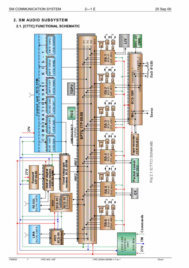
2. SM AUDIO SUBSYSTEM 2.1. [СТТС] FUNCTIONAL SCHEMATIC

SM COMMUNICATION SYSTEM 2—2 E 25 Sep 00
Г908/00 1 17КС.403 –00Г 17КС.0000А-0ИЭ80 ч.7 кн.1 Лист
2.2. [СТТС] OPERATIONAL FEATURES
1. [СТТС] setup can be activated only via ИнПУ or via КРЛ 2. pb СТТС Reinit on RS Laptop does not deactivate Regul and
Lira RCVR-XMTR. MCC activates and deactivates Regul and Lira 3. )PAGE – speakers on all ПА are activated except the speaker which pb is pressed 4. *XMIT on any ПА - ! LED XMIT on all ПА 5. In case of system configuration change (new mode selection)
ПА √ " XMIT (+XMIT)
NOTE For transmission use push-to-talk button on push-to-talk unit or pb XMIT
on ПА (push-to-talk button remains depressed). In this case: on ПА on RS Laptop СМ:БРТК:СТТС
! LED XMIT 1(2, 3) ( , )
2.3. [СТТС] INITIAL CONFIGURATION ППС-22 (308)
1. √ # МБС
All ПА 2. √ + All pb " All LEDs
СМ:БРТК:СТТС RS Laptop
3.
√ all units and channels (Regul and Lira units can be blue) (to deactivate % pb СТТС Reinit)
SM COMM CONTROL ИнПУ 4. √ SM COMM READY INIT ON !
SM COMM -STATUS
√ VHF 1 SQUELCH ON ! " VHF 1 SQUELCH PWR OFF √ VHF 2 SQUELCH ON ! " VHF 2 SQUELCH PWR OFF √ VHF 1 OFF " " RCVR VHF 1 √ VHF 2 SIMPLEX OFF " √ VHF 2 DUPLEX OFF " " RCVR 1 VHF 2
√ EVA CO MM OFF " " RCVR 2 VHF 2
УСБ-14МХ УСБ-14МД УСБ-14МБВ
СТТС preparation

SM COMMUNICATION SYSTEM 2—3 E 25 Sep 00
Г908/00 1 17КС.403 –00Г 17КС.0000А-0ИЭ80 ч.7 кн.1 Лист
2.4. INTERNAL COMMUNICATION
ПА (in use) 1. ) and hold PAGE Page a crewmember using the low-noise headset 2. * ICOM ! ICOM Communicate To complete comm 3. + ICOM " ICOM
2.5. CONTROL VIA Laptop
2.5.1. REGUL COMM ! LED REGUL (when operating via НИП extra ! VHF)
RS Laptop СМ:БРТК:СТТС When operating via relay satellite
When operating via НИП
ПА (in use)
* CHANNEL 1 ! CHANNEL 1 To complete comm
" LED REGUL REGUL √ + XMIT " LED XMIT 1 + CHANNEL 1 " CHANNEL 1
2.5.2. LIRA COMM ! LED LIRA
RS Laptop СМ:БРТК:СТТС
ПА (in use)
* CHANNEL 2 ! CHANNEL 2 To complete comm
" LED LIRA LIRA
√ + XMIT " LED XMIT 2
+ CHANNEL 2 " CHANNEL 2
LIRA
ВСБ-94
LIRA
ВСБ-94
LIRA
REGUL1(2)
ВСБ-92(93)
REGUL1(2)
ВСБ-92(93)
REGUL1(2)
REGUL
VHF REGUL

SM COMMUNICATION SYSTEM 2—4 E 25 Sep 00
Г908/00 1 17КС.403 –00Г 17КС.0000А-0ИЭ80 ч.7 кн.1 Лист
2.5.3. VHF COMM 1. COMMUNICATION SETUP
NOTE Use VHF2s for comm during rendezvous and docking with Soyuz and Orbiter
RS Laptop СМ:БРТК:СТТС
Mode selection Mode deactivation VHF1 cmd: U_ONUK1 (VHF1 ON)
Execute cmd: U_OFUK1 (VHF1 OFF) Execute
VHF2d cmd: U_ONUK2D (VHF2 duplex ON) Execute
cmd: U_OFUK2D (VHF2 duplex OFF) Execute
VHF2s cmd: U_ONUK2S (VHF2 simplex ON) Execute
cmd: U_OFUK2S (VHF2 simplex OFF) Execute
2. VHF1 COMM RS Laptop СМ:БРТК:СТТС ПА (in use) * CHANNEL 2 ! CHANNEL 2
To complete comm √ + XMIT " LED XMIT 2 + CHANNEL 2 " CHANNEL 2
3. VHF2 DUPLEX COMM RS Laptop СМ:БРТК:СТТС ПА (in use) * CHANNEL 3 ! CHANNEL 3
To complete comm √ + XMIT " LED XMIT 3 + CHANNEL 3 " CHANNEL 3
4. VHF2 SIMPLEX COMM
NOTE For reception via VHF2s, release push-to-talk button (" LED XMIT 3)
RS Laptop СМ:БРТК:СТТС
√ " LED XMIT 1, 2, 3 (all ПА +XMIT) ПА (in use) * CHANNEL 3 ! CHANNEL 3
To complete comm √ + XMIT " LED XMIT 3 + CHANNEL 3 " CHANNEL 3
УСБ-14МХУСБ-24Н
УСБ-24Н
УСБ-14МДУСБ-24В
УСБ-24В
УСБ-14МБВУСБ-24В
УСБ-24В

SM COMMUNICATION SYSTEM 2—5 E 25 Sep 00
Г908/00 1 17КС.403 –00Г 17КС.0000А-0ИЭ80 ч.7 кн.1 Лист
2.5.4. REGUL- VHF2 DUPLEX RELAY ! LED XMIT 3 (mode selected)
If " LED XMIT 3
RS Laptop СМ:БРТК:СТТС
ПА To select mode
RS Laptop СМ:БРТК:СТТС cmd: U_ONRTRREGUK2 (Regul-VHF2 relay ON) Execute
ПА ! LED XMIT 3
For comm with MCC with manned vehicle or Orlan
* CHANNEL 1 ! CHANNEL 1
* CHANNEL 3 ! CHANNEL 3
To complete comm + CHANNEL 1, 3 " CHANNEL 1, 3 √ + XMIT " LED XMIT 3
If ! LED XMIT 3
ПА (in use)
To deactivate mode RS Laptop СМ:БРТК:СТТС
cmd: U_OFRTRREGUK2 (Regul-VHF2 relay OFF) Execute
ПА " LED XMIT 3
RS Laptop СМ:БРТК:СТТС
2.5.5. LIRA-VHF2 DUPLEX RELAY ! LED XMIT 3 (mode selected)
If " LED XMIT 3 RS Laptop СМ:БРТК:СТТС
ПА To select mode
RS Laptop СМ:БРТК:СТТС cmd: U_ONRTRLIRUK2 (Lira-VHF2 relay ON) Execute
ПА ! LED XMIT 3
For comm with MCC with manned vehicle or Orlan
* CHANNEL 2 ! CHANNEL 2
* CHANNEL 3 ! CHANNEL 3
To complete comm + CHANNEL 2, 3 " CHANNEL 2, 3 √ + XMIT " LED XMIT 3
If ! LED XMIT 3
ПА (in use)
To deactivate mode RS Laptop СМ:БРТК:СТТС
cmd: U_OFRTLIRUK2 (Lira-VHF2 relay OFF) Execute
ПА " LED XMIT 3
RS Laptop СМ:БРТК:СТТС
ВСБ-92(93)
УСБ-14МД УСБ-24В
ВСБ-92(93) УСБ-14МД УСБ-24В
ВСБ-94 УСБ-14МД УСБ-24В
ВСБ-94
УСБ-14МД УСБ-24В
SM COMMUNICATION SYSTEM 2—6 E 25 Sep 00
Г908/00 1 17КС.403 –00Г 17КС.0000А-0ИЭ80 ч.7 кн.1 Лист
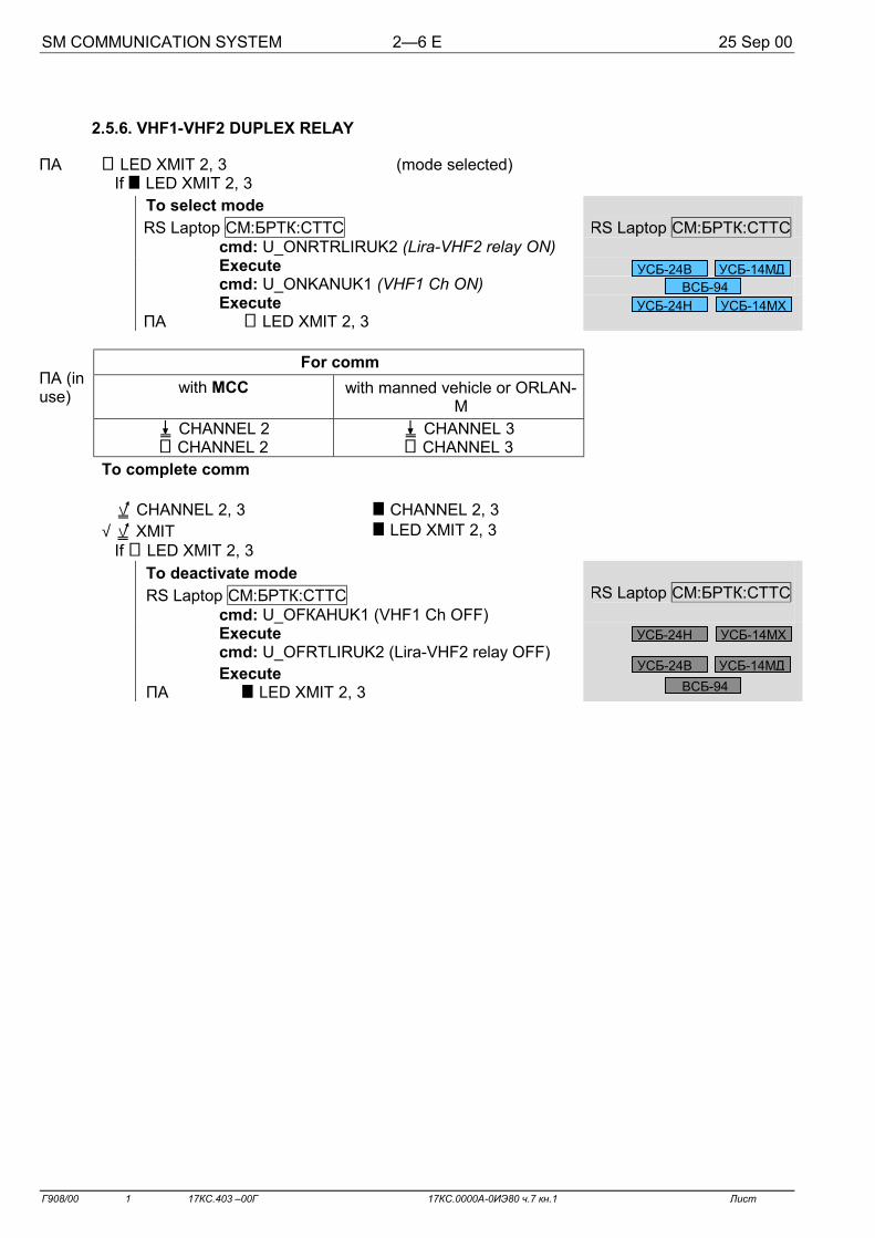
2.5.6. VHF1-VHF2 DUPLEX RELAY
! LED XMIT 2, 3 (mode selected) If " LED XMIT 2, 3
RS Laptop СМ:БРТК:СТТС
ПА To select mode
RS Laptop СМ:БРТК:СТТС cmd: U_ONRTRLIRUK2 (Lira-VHF2 relay ON) Execute cmd: U_ONKANUK1 (VHF1 Ch ON) Execute
ПА ! LED XMIT 2, 3
For comm
with MCC with manned vehicle or ORLAN-M
* CHANNEL 2 ! CHANNEL 2
* CHANNEL 3 ! CHANNEL 3
To complete comm
+ CHANNEL 2, 3 " CHANNEL 2, 3 √ + XMIT " LED XMIT 2, 3
If ! LED XMIT 2, 3
ПА (in use)
To deactivate mode RS Laptop СМ:БРТК:СТТС
cmd: U_OFКАНUK1 (VHF1 Ch OFF) Execute cmd: U_OFRTLIRUK2 (Lira-VHF2 relay OFF) Execute
ПА " LED XMIT 2, 3
RS Laptop СМ:БРТК:СТТС
УСБ-14МХ УСБ-24Н ВСБ-94
УСБ-14МД УСБ-24В
УСБ-14МХ УСБ-24Н
ВСБ-94 УСБ-14МД УСБ-24В

SM COMMUNICATION SYSTEM 2—7 E 25 Sep 00
Г908/00 1 17КС.403 –00Г 17КС.0000А-0ИЭ80 ч.7 кн.1 Лист
2.5.7. EVA COMM
1. PREPARATION FOR EVA behind panel 406 bottom right
cnctr X796 ' plate cnctr X796 cap ' cnctr X796-1 cnctr X796 ( plate cnctr X796-1
(disconnect ПСС annunciation unit from [СТТС]) (connect ПОВ annunciation unit to [СТТС])
ПА-5(ПхО) Low-noise headset ' ПА and transfer into [РО] 2. EVA COMM USING THE ORLAN UMBILICAL
NOTE The IV crewmember (on MCC-M GO), or MCC establishes comm via
VHF1(2d), Regul, Lira
Prior to Orlan donning ПА-5(ПхО) * CHANNEL 1, 2, 3
* XMIT ! CHANNEL 1, 2, 3 ! LED XMIT 1, 2, 3
After Orlan doffing + XMIT " LED XMIT 1, 2, 3 + CHANNEL 1, 2, 3 " CHANNEL 1, 2, 3
3. EVA COMM USING БРТА
NOTE 1. Comm is performed via ПО-4М panel of the ORLAN-M Korona system 2. IV crewmember (on MCC-M GO), or MCC establishes Regul-VHF2
duplex relay on board (Lira-VHF2d, VHF1-VHF2d)
Prior to Orlan donning RS Laptop СМ:БРТК:СТТС
cmd: U_ONSVEXIT (EVA Comm ON) Execute
RS Laptop СМ:БРТК:СТТС
ПА-5(ПхО) * CHANNEL 3 * XMIT
! CHANNEL 3 ! LED XMIT 3
After Orlan doffing + XMIT " LED XMIT 3 + CHANNEL 3 " CHANNEL 3
RS Laptop СТТС cmd: U_OFSVEXIT (EVA Comm OFF) Execute
4. CLOSEOUT OPERATIONS ПА-5(ПхО) Low-noise headset ( ПА behind panel 406 bottom right
cnctr X796 ' plate cnctr X796-1 cap ( cnctr X796-1 cnctr X796 ( plate cnctr 796
УСБ-24Г
УСБ-24В УСБ-14МД
УСБ-24В УСБ-14МД
УСБ-24Г

SM COMMUNICATION SYSTEM 2—8 E 25 Sep 00
Г908/00 1 17КС.403 –00Г 17КС.0000А-0ИЭ80 ч.7 кн.1 Лист
2.6. CONTROL VIA ИнПУ
2.6.1. VHF COMM 1. COMMUNICATION
NOTE Use VHF2s for comm during approach and docking with Soyuz and Orbiter
ИнПУ SM STATUS SM COMM
Mode activaiton Mode deactivation VHF1 VHF 1 ON ! VHF 1 VHF 1 OFF " VHF 1 VHF2d VHF 2d ON ! VHF 2d VHF 2d OFF " VHF 2d VHF2s VHF 2s ON ! VHF 2s VHF 2s OFF " VHF 2d 2. VHF1 COMM ИнПУ SM COMM SIG ПА (in use) * CHANNEL 2 ! CHANNEL 2 ! RCVR VHF 1 To complete comm
√ + XMIT " LED XMIT 2 + CHANNEL 2 " CHANNEL 2 " RCVR VHF 1
3. VHF2 DUPLEX COMM ИнПУ SM COMM SIG ПА (in use) * CHANNEL 3 ! CHANNEL 3 ! RCVR 1 VHF 2 To complete comm
√ + XMIT " LED XMIT 3 + CHANNEL 3 " CHANNEL 3 " RCVR 1 VHF 2
4. VHF2 SIMPLEX COMM
NOTE For reception via VHF2s, release push-to-talk button (" LED XMIT 3)
ИнПУ SM COMM SIG
√ " LED XMIT 1,2,3 (all ПА +XMIT ) ПА (in use) * CHANNEL 3 ! CHANNEL 3 ! RCVR 1 VHF 2
To complete comm √ + XMIT " LED XMIT 3 + CHANNEL 3 " CHANNEL 3 " RCVR 1 VHF 2

SM COMMUNICATION SYSTEM 2—9 E 25 Sep 00
Г908/00 1 17КС.403 –00Г 17КС.0000А-0ИЭ80 ч.7 кн.1 Лист
2.6.2. EVA COMM
1. PREPARATION FOR EVA behind panel 406 bottom right
cnctr X796 ' plate cnctr X796 cap ' cnctr X796-1 cnctr X796 ( plate cnctr X796-1
(disconnect ПСС annunciation unit from [СТТС]) (connect ПОВ annunciation unit to [СТТС])
ПА-5(ПхО) Low-noise headset ' ПА and transfer into [РО]
2. EVA COMM USING THE ORLAN UMBILICAL
NOTE Crewmember (on MCC-M GO) or MCC performs comm via
VHF1(2d), Regul, Lira
Prior to Orlan donning ПА-5(ПхО) * CHANNEL 1, 2, 3
* XMIT ! CHANNEL 1, 2, 3 " LED XMIT 1, 2, 3
After Orlan doffing + XMIT " LED XMIT 1, 2, 3 + CHANNEL 1, 2, 3 " CHANNEL 1, 2, 3
3. EVA COMM USING БРТА
NOTE 1. Comm is performed via ПО-4М panel of the ORLAN-M Korona system 2. Crewmember (on MCC-M GO) or MCC performs Regul-VHF2
duplex relay on board (Lira-VHF2d, VHF1-VHF2d)
Prior to Orlan donning SM STATUS SM COMM ИнПУ SM COMM SIG ИнПУ EVA COMM ON VHF 2 DUPLEX ON
! !
! RCVR 1 VHF 2, RCVR 2 VHF 2
ПА-5(ПхО) * CHANNEL 3 * XMIT
! CHANNEL 3 ! LED XMIT 3
After Orlan doffing + XMIT " LED XMIT 3 + CHANNEL 3 " CHANNEL 3
SM COMM ИнПУ EVA COMM OFF VHF 2 DUPLEX OFF
" "
" RCVR 1 VHF 2, RCVR 2 VHF 2
4. CLOSEOUT OPERATIONS ПА-5(ПхО) Low-noise headset ( ПА behind panel 406 bottom right
cnctr X796 ' plate cnctr X796-1 cap ( cnctr X796-1 cnctr X796 ( plate cnctr 796

SM COMMUNICATION SYSTEM 2—10 E 25 Sep 00
Г908/00 1 17КС.403 –00Г 17КС.0000А-0ИЭ80 ч.7 кн.1 Лист
2.7. INTERMODULE COMMUNICATION SETUP
Comm from docked vehicles on SM: Channel 1(FGB, Soyuz) Channel 2(FGB)
SM ПА-3 pnl 228 SM ПА-2 pnl 407 Select required comm mode per 2.4-2.6
2.8. COMM FROM FGB
SM ПА-3(2) 1. Select required comm mode per 2.7 FGB БВК-2 (313) 2. * ON ! LED ([СТС] is powered from FGB СЭП)
To perform comm ВСБ-95 3. * CHANNEL 1(2) ! CHANNEL 1(2)
To complete comm 4. + CHANNEL 1(2) " CHANNEL 1, 2 √ +XMIT " LED XMIT 1, 2 БВК 2 (313) 5. ) OFF " LED ([СТС] is powered from SM СЭП) SM ПА-3(2) 6. + All pb " All LEDs
2.9. COMM FROM DOCKED SOYUZ VIA INTERMODULE COMMUNICATION
SM ПА-3 (228) 1. Select required comm mode per 2.4 – 2.6 *XMIT ! LED XMIT 1(2, 3) SOYUZ
2.
Perform Intermodule Communication per RODF: SOYUZ TM ”ASCENT AND DESCENT” CHECKLIST, п.1.3 INFLIGHT COMMUNICATION OPERATIONS
SM ПА-3 3. + All pb " All LEDs

SM COMMUNICATION SYSTEM 2—11 E 25 Sep 00
Г908/00 1 17КС.403 –00Г 17КС.0000А-0ИЭ80 ч.7 кн.1 Лист
2.10. PACKET COMM
NOTE
1. If there is no RS Laptop, MCC-M outputs command D_ ONF3URM (УРМ Ф3 ON) via КРЛ 2. The names of files for transmission should not have more than 8 symbols (English letters and digits) and should not have attributes «Only reading» 3. Do not add files to folder D:\US_TTS\D_SEND\TTSEND until transmission is complete
Prior to comm pass
WienerPower
1. Prepare and place files into folder D:\US_TTS\D_SEND\TTSEND
RS Laptop
2. СМ:БРТК:СТТС cmd: D_ONF3URM (УРМ Ф3 ON) (telephone-telegraph comm УС activation) Execute
During comm pass ПА-4 3. Set up comm for packet transmission (On MCC-M GO)
Regulator ТЛФ 2 maximum, ТЛФ 1 minimum * XMIT ! LED XMIT 1(2, 3) WienerPower
4. Start WS_TTS3 program from folder D:\US_TTS\
If there is no packet transmission via Regul 1(2)
RS Laptop СТТС √ (On MCC-М GO cmd: U_ONTLFREG16 (Regul 16 Telephone ON) Execute)
After file exchange is complete , window ‘Reports about comm pass’
, window ‘List of delivered files’
, window ‘List of received files’
‘Comm pass was performed without mistakes’
(‘Comm pass was performed with mistakes’)
Files not transmitted during comm pass
Files received during comm pass
After comm pass is complete 5. Exit the program WS_TTS3.EXE
ПА-4 6. + XMIT " LED XMIT 1, 2, 3 To deactivate mode
RS Laptop
7. СТТС D_OFF3URM (УРМ Ф3 OFF) (telephone-telegraph comm УС deactivation)
After comm pass is complete WienerPower
8. Take received files from folder D:\US_TTS\D_RECV\OTP
ВСБ-92

SM COMMUNICATION SYSTEM 2—12 E 25 Sep 00
Г908/00 1 17КС.403 –00Г 17КС.0000А-0ИЭ80 ч.7 кн.1 Лист
2.11. GNOM-S TAPE RECORDER OPERATION
NOTE 1. When tape recorder is activated, track 1 is preset automatically 2. The initial configuration of the new cassette is in middle position 3. Switchover to the other track is automatic 4. For forced switchover * direction 1(2) 5. One track operation time is 1 hour 30 min
1. RECORD ПА-3 * CHANNEL 1(2, 3) ! CHANNEL 1(2, 3) or * ICOM ! ICOM Tape recorder Switch → ∇∇∇∇ * On ! 1(2) * Off (after recording is complete) ПА-3 + CHANNEL 1, 2, 3, ICOM " CHANNEL 1, 2, 3, ICOM
2. PLAYBACK ПА-3 * CHANNEL 1(2, 3) ! CHANNEL 1(2, 3) or * ICOM ! ICOM For transmission to MCC *XMIT ! LED XMIT 1(2, 3) Tape recorder Switch → ∆∆∆∆ * On ! 1(2) * Off (after playback is complete) ПА-3 + CHANNEL 1, 2, 3, ICOM " CHANNEL 1, 2, 3, ICOM
3. REWIND Tape recorder Switch → >>>>>>>> * On *1(2) (to choose direction) !1(2) * Off (to stop)
4. CASSETTE REPLACEMENT Tape recorder ) CASSETTE, Retrieve cassette Insert new cassette Close cover Switch → >>>>>>>> * On * 2 !2 , Counter → 2-3 points * Off

SM COMMUNICATION SYSTEM 2—13 E 25 Sep 00
Г908/00 1 17КС.403 –00Г 17КС.0000А-0ИЭ80 ч.7 кн.1 Лист
Notes

SM COMMUNICATION SYSTEM 2—14 E 25 Sep 00
Г908/00 1 17КС.403 –00Г 17КС.0000А-0ИЭ80 ч.7 кн.1 Лист
2.12. [СТТС] FUNCTIONAL CHECK
ПА ) TEST RESET ! all LEDs " FUSE
2.12.1. SIDETONE CHECK ПА * CHANNEL 1 ! CHANNEL 1 ) and hold push-to-talk button ! LED XMIT 1 Perform sidetone, check volume Release push-to-talk button " LED XMIT 1 + CHANNEL 1 " CHANNEL 1
2.12.2. COMM CALL CHECK
NOTE
When pressing pb PAGE all ПА speakers are activated, except the speaker via which check is being performed
ПА Deactivate all speakers ) and hold pb PAGE Page a crewmember from SM (module) using the low-noise headset
2.12.3. PAGE CHECK ПА-1 1. * ICOM ! ICOM ПА 2—6 2. * ICOM (in turn from 2 to 6) Perform comm check using the low-noise headset, volume & * SPKR ON Perform comm check using the speaker, volume & All ПА 3. + ICOM " ICOM
2.12.4. ALARM ANNUNCIATION CHECK (during comm pass) ИнПУ 1. SM STATUS SM COMM On MCC-M GO SM COMM READY INIT OFF " SM COMM READY INIT To MCC-M 2. Comm call (КРЛ Б-К5) TONE ИнПУ 3. SM COMM √ ! SM COMM READY INIT Report to MCC-M

SM COMMUNICATION SYSTEM 2—15 E 25 Sep 00
Г908/00 1 17КС.403 –00Г 17КС.0000А-0ИЭ80 ч.7 кн.1 Лист
2.12.5. VHF RECEIVER FUNCTIONAL CHECK
SM STATUS SM COMM ИнПУ 1. VHF 1 ON ! VHF 1
ИнПУ SM COMM SIG
ПА * CHANNEL 2 ! CHANNEL 2 ! RCVR VHF 1 SM COMM
VHF 1 SQUELCH OFF " VHF 1 SQUELCH ! VHF 1 SQUELCH PWR OFF
- RCVR VHF 1 via the low-noise headset
ИнПУ
VHF 1 SQUELCH ON ! VHF 1 SQUELCH " VHF 1 SQUELCH PWR OFF ПА + CHANNEL 2 " CHANNEL 2 " RCVR VHF 1
SM COMM VHF 1 OFF
" VHF 1
ИнПУ
2. VHF 2 DUPLEX OFF ! VHF 2 DUPLEX
ПА * CHANNEL 3 ! CHANNEL 3 ! RCVR 1 VHF 2
SM COMM VHF 2 SQUELCH OFF
" VHF 2 SQUELCH ! VHF 2 SQUELCH PWR OFF
- RCVR 1 VHF 2 noise via the low-noise headset
ИнПУ
VHF 2 SQUELCH ON ! VHF 2 SQUELCH " VHF 2 SQUELCH PWR OFF ПА + CHANNEL 3 " CHANNEL 3 " RCVR 1 VHF 2
SM COMM VHF 2 DUPLEX OFF
" VHF 2 DUPLEX
ИнПУ
3. EVA COMM ON ! EVA COMM
ПА * CHANNEL 3 ! CHANNEL 3 ! RCVR 2 VHF 2
SM COMM VHF 2 SQUELCH OFF
" VHF 2 SQEULCH ! VHF 2 SQUELCH PWR OFF
- RCVR 2 VHF2 noise via the low-noise headset
ИнПУ
VHF 2 SQUELCH ON ! VHF 2 SQUELCH " VHF 2 SQUELCH PWR OFF ПА + ЛИНИЯ СВЯЗИ 3 " ЛИНИЯ СВЯЗИ 3 " RCVR 2 VHF 2
ИнПУ SM COMM EVA COMM OFF
" EVA COMM

SM COMMUNICATION SYSTEM 2—16 E 25 Sep 00
Г908/00 1 17КС.403 –00Г 17КС.0000А-0ИЭ80 ч.7 кн.1 Лист
Notes

SM COMMUNICATION SYSTEM 2—17 E 25 Sep 00
Г908/00 1 17КС.403 –00Г 17КС.0000А-0ИЭ80 ч.7 кн.1 Лист
2.13. OFF-NOMINAL SITUATIONS
2.13.1. NO COMM VIA LOW-NOISE HEADSET ПА If ! FUSE Replace fuse Report to MCC-M If " FUSE ПА - comm via second low-noise headset If there is comm Reconnect low-noise headset to be checked to cnctr Х1 of second low-
noise headset - comm via to be checked low-noise headset If there is comm, first cnctr Х1 is bad Work via good cnctr Х1 If there is no comm Replace low-noise headset Report to MCC-M
2.13.2. SWITCHOVER TO BACKUP [СТТС]
(on MCC-M GO)
NOTE Select the operating mode for the desired unit on the RS Laptop or ИнПУ before switching to backup RCVR and XMTR VHF2(2d)
Device Crewmember actions
Tonal telegraph receiver ВСБ-891М
behind pnl 331 Reconnect cbl from cnctr 891-Ш6 to cnctr 891-Ш5 Reconnect cap from cnctr 891-Ш5 to cnctr 891-Ш6
МБС ВСБ-589 pnl 330 $ CHANNEL 1(2) → BACKUP 1. SWITCHOVER VIA Laptop
Device Crewmember actions Note РПУ ВСБ-92
РПУ ВСБ-94
БРТС 17Р 55.58
RS Laptop СМ:БРТК:СТТС cmd: U_ONAKK_R (Backup speaker ON) Execute
Switchover to backup subset is performed by all units at the same time
Digital comm unit 17Р 55.59М
RS Laptop СМ:БРТК:СТТС cmd: U_ON17Р55_R (17Р55.59М backup ON) Execute
RCVR (XMTR) VHF1 УСБ-24Н(УСБ-14МХ)
RS Laptop СМ:БРТК:СТТС cmd: U_ONPRM(PRD)UK1_R (VHF1 backup RCVR1(XMTR) ON) Execute
RCVR1 (2) VHF2 УСБ-24Н(УСБ-24Г)
RS Laptop СМ:БРТК:СТТС cmd: U_ONPRM1(2)UK2_R (VHF2 backup RCVR1(2) ON) Execute
XMTR2s (XMTR2d) VHF2 УСБ-24МБВ(УСБ-14МД)
RS Laptop СМ:БРТК:СТТС cmd: U_ONPRD1(2)UK2_R (VHF2 backup XMTR1(2) ON) Execute

SM COMMUNICATION SYSTEM 2—18 E 25 Sep 00
Г908/00 1 17КС.403 –00Г 17КС.0000А-0ИЭ80 ч.7 кн.1 Лист
2. SWITCHOVER VIA ИнПУ
Device Crewmember actions Note
РПУ ВСБ-92
РПУ ВСБ-94
БРТС 17Р 55.58
ИнПУ SM STATUS SM COMM BU AMPLFR ON !!!! BU AMPLFR
Switchover to backup
subset is performed by
all units at the same
time
RCVR (XMTR) VHF1 ИнПУ SM STATUS SM COMM BU XMTR (RCVR) VHF 1 ON !!!! BU XMTR (RCVR) VHF 1
RCVR 1 (XMTR 1) VHF 2 ИнПУ SM STATUS SM COMM BU XMTR 1 (RCVR 1) VHF 2 ON !!!! BU XMTR 1 (RCVR 1) VHF 2
For VHF2s
RCVR 2 (XMTR 2) VHF 2 ИнПУ SM STATUS SM COMM BU XMTR 2 (RCVR 2) VHF 2 ON !!!! BU XMTR 1 (RCVR 1) VHF 2
For VHF2d

SM COMMUNICATION SYSTEM 2—19 E 25 Sep 00
Г908/00 1 17КС.403 –00Г 17КС.0000А-0ИЭ80 ч.7 кн.1 Лист
Notes

SM COMMUNICATION SYSTEM 3—1 E 25 Sep 00
Г908/00 1 17КС.403 –00Г 17КС.0000А-0ИЭ80 ч.7 кн.1 Лист
3. TELEVISION SUBSYSTEM
3.1. [ТВС] FUNCTIONAL SCHEMATIC
B/u
Pri
B/u
Pri
Pri
B/u
Pri
АФУ
GOST/PAL/MAC
SEKAM/PAL//MAC
SECAM
SECAM
SEKAM/PAL(ВКУ)
LIRA RCVR-XMTR
B/u Pri БРТС
LIRA
Pri
B/u
Pri
Pri
B/u
B/u
B/u
B/u
B/u
B/u
Pri
Pri
Pri
Pri
Pri
Pri
ПхО SPP СО-1
ПрК
КЛ-160М БУВУ КУ-110М
Regenerator КЛ-161
RCVR КЛ-123-М
XMTR КЛ-108А
C
O
M
M
U
T
A
T
O
R
Т/К КЛ-140-СТМ(+Х)
ss
Simvol-Ts
ss
Т/К КЛ-140-СТМ(-Х)
Т/К КЛ-103-Ц В/К МОНИТОР
К ШЕР К ШЕР КОДЕР VTR
В/К
LIV
MONITOR
БУВР КУ-120М
Pri
ВКУ-2
ВКУ-1
АФУ
ТМО
Relay ТV2 FGB Transmission ТV2 FGB
ЦВКУ1
ЦВКУ2
П П С 2 1
PAL
SECAM
MAC
MAC
PAL
GOST
GOST
SEKAM/PAL
SEKAM/PAL(VTR)
MAC
SECAM
SECAM
Primary set
SEKAM/PAL//MAC
Figure 3.1 [ТВС] Functional Schematic
БУВУ - Temporary multiplexing onboard device ss - sync signal БУВР - Temporary demultiplexing onboard device Pri - primary ТМО - Signal converter B/u - backup

SM COMMUNICATION SYSTEM 3—2 E 25 Sep 00
Г908/00 1 17КС.403 –00Г 17КС.0000А-0ИЭ80 ч.7 кн.1 Лист
3.2. [ТВС] OPERATING MODES

SM COMMUNICATION SYSTEM 3—3 E 25 Sep 00
Г908/00 1 17КС.403 –00Г 17КС.0000А-0ИЭ80 ч.7 кн.1 Лист
3.3. SCHEMATIC OF PREPARATION FOR VIDEO EVENT AND VIDEO EVENT FROM SM

SM COMMUNICATION SYSTEM 3—4 E 25 Sep 00
Г908/00 1 17КС.403 –00Г 17КС.0000А-0ИЭ80 ч.7 кн.1 Лист
3.4. SCHEMATIC OF PREPARATION FOR VIDEO EVENT AND VIDEO EVENT FROM FGB

SM COMMUNICATION SYSTEM 3—5 E 25 Sep 00
Г908/00 1 17КС.403 –00Г 17КС.0000А-0ИЭ80 ч.7 кн.1 Лист
3.5. [ТВС] OPERATION FEATURES
3.5.1. TV DEACTIVATION PROCEDURE FEATURES After TV deactivation procedure (F25_TVS_26) is executed to deactivate TV blue highlights of display
elements СМ:БРТК:TV System disappear for all units, except LIRA RCVR and XMTR which are controlled by MCC-M and can be left highlighted. In this case: deactivated: not deactivated:
Т/К КЛ-140СТ-М+Х LIRA RCVR Т/К КЛ-140СТ-М-Х LIRA XMTR Т/К КЛ-103Ц ВКУ 1, 2 XMTR КЛ-108А LIV БУВР КУ-120М TV lighting БУВУ КУ-110М RCVR КЛ-123-М Regenerator КЛ-161 Commutator КЛ-160М
3.5.2. FEATURES OF [ТВС] OPERATING MODE SELECTION USING COMMANDS
CAUTION
Simultaneous operation of KLEST transmitter and receiver is not allowed
1. COMMUTATOR КЛ-160М CONNECTION RS Laptop СМ:БРТК:TV System cmd: I_ONPKL160T (КЛ-160 power ON) Execute КЛ-160М 2. TV SIGNAL SOURCE CONNECTION RS Laptop TV System cmd: (source activation command is given in Table 3.2) Execute selected source
3. TV SIGNAL USER CONNECTION
NOTE 1. Signal degrades if more than three users are simultaneously
connected to one source 2. When mode is selected using commands, ВКУ1(2), ВКУ Simvol units
and lines connecting them on display TV System do not appear
RS Laptop TV System cmd: (user activation command is given in Table 3.2) Execute selected user
4. OPERATION CLOSEOUT RS Laptop ТВС proc: F25_TVS_26 (Television OFF) Execute Blue highlights disappear
Primary set

SM COMMUNICATION SYSTEM 3—6 E 25 Sep 00
Г908/00 1 17КС.403 –00Г 17КС.0000А-0ИЭ80 ч.7 кн.1 Лист
3.6. VIDEO EVENT FROM SM (DOWNLINK)
1. PREPARATION FOR VIDEO EVENT Remove Т/К protective covers Inspect Т/К for damage and ensure optical surfaces are clean
For video event from [РО] For video event from ПхО
318 cnctr Х4Ю29(TV ПхО) ( cnctr Х1Ю29 Configure equipment for video event from [РО] per Figure 3.3, p. 3-3 Configure equipment for video event from ПхО per Figire 3.3, p. 3-3
2. TV SIGNAL MONITORING ON ВКУ1(2) 1. If necessary install and connect lights per RODF: SM POWER SUPPLY SYSTEM, СПР-1 PORTABLE TV LAMP SETUP AND OPERATION
ППС-21(306) 2. # ЦВКУ1(2)
RS Laptop СМ:БРТК:TV System proc: F25_TVS_31(TVS_32) (Connect TV (portable) to MON1(2)) Execute
Cam (portable) MON1(2) cmd: I_ONPSVETT (TV Lighting power ON) Execute Adjust lighting
3. TV SIGNAL TRANSMISSION TO MCC (on MCC-M GO)
NOTE KLEST transmitter takes 2 min to start operating mode
RS Laptop TV System proc: F25_TVS_12(TVS_13) (Connect color TV(portable) to TV XMTR (XMTR L) ГОСТ) Execute
or Cam (portable) Perform video event 4. OPERATION CLOSEOUT RS Laptop TV System proc: F25_TVS_26 (Television OFF) Execute Blue highlights disappear cmd: I_OFPSVETT (TV lighting power OFF) Execute ППС-21(306) $ ЦВКУ1(2)
LIRA XMTR TV XMTR

SM COMMUNICATION SYSTEM 3—7 E 25 Sep 00
Г908/00 1 17КС.403 –00Г 17КС.0000А-0ИЭ80 ч.7 кн.1 Лист
3.7. EVA VIDEO EVENTS (DOWNLINK)
1. Т/К FUNCTIONAL CHECK 1. Remove Т/К protective covers Inspect Т/К for damage and ensure optical surfaces are clean
Configure equipment:
For video event outside [РО] For video event in ПхО
318 cnctr Х4Ю29(TV ПхО) ( cnctr Х1Ю29 Preparation for EVA video event outside [РО] Figure 3.3, p. 3-3 EVA video event from ПхО
Figure 3.3, p. 3-3
ППС-21(306) 2. # ЦВКУ1(2)
RS Laptop СМ:БРТК:TV System proc: F25_TVS_31(TVS_32) (Connect TV (portable) to MON1(2)) Execute
Cam (portable) MON1(2) , Т/К operation
RS Laptop TV System proc: F25_TVS_26 (Television OFF) Execute Blue highlights disappear ППС-21(306) $ ЦВКУ1(2)
2. PREPARATION FOR VIDEO EVENT
CAUTION
Do not touch Т/К housing with bare hands after cover removal When operating Т/К, hold it only by its handle while wearing gloves
1. Remove Т/К cover Install Т/К on boom 17КС.Б9648-0 (to secure camera on handrails)
318 2. cnctr Х8Ю29 cbl 17КС.29Ю 8029А-10' cnctr Х1Ю29 cnctr Х12Ю29(EVA TV) ( cnctr Х1Ю29 cnctr X6Ю29 cbl 17КС.29Ю 8029А-20 ' cnctr X6Ю29 cbl 17КС.29Ю 8029А-10
3. VIDEO EVENT FROM [РО] SMALL CONE
Locking plate # 5 √ cnctr ХФП5-2 ' cnctr ХФП5-3 cnctr ХФП5-2 ( cnctr Х6Ю29 cbl 17КС.29Ю 8029А-20 (Figure 3.3, p. 3-3)
4. VIDEO EVENT FROM [РО] LARGE CONE
Locking plate # 5 √ cnctr ХФП5-2 ( cnctr ХФП5-3 Locking plate # 6 cnctr ХФП6-1 ( cnctr Х6Ю29 cbl 17КС.29Ю 8029А-20 (Figure 3.3, p. 3-3)

SM COMMUNICATION SYSTEM 3—8 E 25 Sep 00
Г908/00 1 17КС.403 –00Г 17КС.0000А-0ИЭ80 ч.7 кн.1 Лист
5. TV SIGNAL MONITORING ONBOARD
ППС-21(306) # ЦВКУ1(2)
RS Laptop СМ:БРТК:TV System proc: F25_TVS_31(TVS_32) (Connect TV (portable) to MON1(2)) Execute
Cam (portable) MON1(2) 6. TV SIGNAL TRANSMISSION TO MCC (on MCC-M GO)
NOTE
KLEST transmitter takes 2 min to start operating mode
proc: F25_TVS_12(TVS_13) (Connect color TV(portable) to TV XMTR ГОСТ) Execute
or Cam (portable)
7. OPERATION CLOSEOUT RS Laptop 1. TV System proc: F25_TVS_26 (Television OFF) Execute Blue highlights disappear ППС-21(306) $ ЦВКУ1(2) Locking plate # 6 2. √ cnctr ХФП6-1 ' cnctr Х6Ю29 cbl 17КС.29Ю 8029А-20 (Figure 3.3, p. 3-3) Locking plate # 5 √ cnctr ХФП5-2 'cnctr Х6Ю29 cbl 17КС.29Ю 8029А-20 √ cnctr ХФП5-2 ( cnctr ХФП5-3 3. Cover Т/К Disassemble equipment Stow cables and Т/К
LIRA XMTR TV XMTR

SM COMMUNICATION SYSTEM 3—9 E 25 Sep 00
Г908/00 1 17КС.403 –00Г 17КС.0000А-0ИЭ80 ч.7 кн.1 Лист
3.8. TV SIGNAL TRANSMISSION FROM EXTERNAL Т/К TO MCC (DOWNLINK)
NOTE 1. On MCC-M GO activate in advance external Т/К for warming up 2. After docking to FGB, field of view from Т/К-Х is obstructed 3. To record on LIV VTR prepare per RODF: SM VIDEO & AUDIO,
RECORDING FROM EXTERNAL DEVISE
3.8.1. OPERATION IN ВКУ MODE 1. TV SIGNAL MONITORING ON ВКУ ППС-21(306) # ЦВКУ1(2) RS Laptop СМ:БРТК:TV System proc: F25_TVS_27(TVS_28) (Connect TV +x to MON1(2)) Execute
Cam +Х MON1(2) 2. TV SIGNAL TRANSMISSION VIA KLEST TRANSMITTER (on MCC-M GO)
NOTE
KLEST transmitter takes 2 min to start operating mode
RS Laptop TV System proc: F25_TVS_0(TVS_3) (Connect TV (КЛ-140СТ) +х (-x) to TV XMTR) Execute Cam +Х(-Х) 3. TV SIGNAL TRANSMISSION VIA LIRA TRANSMITTER (on MCC-M GO)
RS Laptop TV System proc: F25_TVS_1(TVS_4) (Connect TV (КЛ-140СТ) +х (-x) to Lira XMTR) Execute Cam +Х(-Х) 4. OPERATION CLOSEOUT RS Laptop TV System proc: F25_TVS_26 (Television OFF) Execute Blue highlights disappear ППС-21(306) $ ЦВКУ1(2)
LIRA XMTR
TV XMTR

SM COMMUNICATION SYSTEM 3—10 E 25 Sep 00
Г908/00 1 17КС.403 –00Г 17КС.0000А-0ИЭ80 ч.7 кн.1 Лист
3.8.2. OPERATION IN TV DISPLAY MODE (during dynamic modes)
1. PREPARATION FOR OPERATION Simvol-Ts Prepare for TV signal reception per RODF: SM MANUAL CONTROLS 2. TV SIGNAL MONITORING ON SIMVOL-Ts
RS Laptop СМ:БРТК:TV System proc: F25_TVS_2(TVS_5) (Connect TV Camera КЛ-140СТ +х (-x) to ЦВКУ Simvol-Ts) Execute
MON Simvol-Ts Cam+Х(-Х) 3. TV SIGNAL RECORDING IN DISPLAY MODE ON VTR
RS Laptop TV System proc: F25_TVS_8(TVS_11) (Connect Display TV with TV (КЛ-140СТ) +x (-x) to recorder) Execute
Cam +Х(-Х) MON LIV recorder Simvol-Ts
4. TV SIGNAL MONITORING VIA Т/К +х IN DISPLAY MODE ON ВКУ
NOTE Mode is off-nominal, image on ВКУ1(2) is flickering with
frequency of 16.5 Hz, color may be degraded
RS Laptop TV System proc: F25_TVS_29(TVS_30) (Connect Display TV +x to MON1(2)) Execute Cam+Х MON MON1(2) Simvol-Ts 5. TV SIGNAL TRANSMISSION VIA KLEST TRANSMITTER IN DISPLAY MODE (on MCC-M GO)
RS Laptop TV System proc: F25_TVS_6(TVS_9) (Connect Display TV with TV (КЛ-140СТ) +x (-x) to TV XMTR) Execute
Cam+Х(-Х) MON Simvol-Ts 6. TV SIGNAL TRANSMISSION VIA LIRA TRANSMITTER IN DISPLAY MODE (on MCC-M GO)
RS Laptop TV System proc: F25_TVS_7(TVS_10) (Connect Display TV with TV (КЛ-140СТ) +x (-x) to Lira XMTR) Execute
Cam +Х(-Х) MON Simvol-Ts
LIRA XMTR
TV XMTR

SM COMMUNICATION SYSTEM 3—11 E 25 Sep 00
Г908/00 1 17КС.403 –00Г 17КС.0000А-0ИЭ80 ч.7 кн.1 Лист
7. OPERATION CLOSEOUT
RS Laptop 1. СМ:БРТК:TV System proc: F25_TVS_26 (Television OFF) Execute Blue highlights disappear Simvol-Ts 2. Deactivate per RODF:SM MANUAL CONTROLS
3.8.3. CAMERA CONTROL
NOTE
To change settings Т/К should be activated
RS Laptop СМ:БРТК:TV System % pb between Cam +X and Cam -X
Command Setting to be changed Note cmd: I_ONPRSVT Execute (Flare reduction ON) In case of local
glares cmd: I_OFPRSVT Execute (Flare reduction OFF)
cmd: I_SFPLT Execute (Strong Filter)
cmd: I_SFSLT Execute (Weak Filter)
cmd: I_SOUUT Execute (Narrow-angle lens)
cmd: I_SOWUT Execute (Wide-angle lens)

SM COMMUNICATION SYSTEM 3—12 E 25 Sep 00
Г908/00 1 17КС.403 –00Г 17КС.0000А-0ИЭ80 ч.7 кн.1 Лист
3.9. TV SIGNAL RECEPTION AND TRANSMISSION FROM SOYUZ (PROGRESS) TO MCC (VIDEO RELAY)
NOTE If recording on LIV VTR operate per RODF: SM VIDEO &
AUDIO, RECORDING FROM EXTERNAL DEVISE
1. TV SIGNAL MONITORING ON ВКУ ППС-21(306) # ЦВКУ1(2) RS Laptop СМ:БРТК:TV System proc: F25_TVS_33(TVS_34) (Connect TV RCVR to MON1(2)) Execute
MON1(2) 2. TV SIGNAL MONITORING ON SIMVOL-Ts (during dynamic modes) Simvol-Ts Prepare for TV signal reception per RODF: SM MANUAL CONTROLS RS Laptop TV System proc: F25_TVS_22 (Connect TV RCVR to ЦВКУ Simvol-Ts) Execute
Simvol-Ts 3. TV SIGNAL TRANSMISSION TO MCC VIA LIRA (on MCC-M GO)
CAUTION
Simultaneous operation of KLEST receiver and transmitter is not allowed
RS Laptop TV System proc: F25_TVS_17 (Connect ТV RCVR to Lira XMTR) Execute 4. OPERATION CLOSEOUT RS Laptop TV System proc: F25_TVS_26 (Television OFF) Execute Blue highlights disappear ППС-21(306) $ ЦВКУ1(2) Simvol-Ts Deactivate per RODF: SM MANUAL CONTROLS
TV RCVR
TV RCVR
TV RCVR LIRA XMTR

SM COMMUNICATION SYSTEM 3—13 E 25 Sep 00
Г908/00 1 17КС.403 –00Г 17КС.0000А-0ИЭ80 ч.7 кн.1 Лист
3.10. TV SIGNAL RECEPTION FROM MCC (UPLINK)
NOTE If recording on LIV VTR operate per RODF: SM VIDEO &
AUDIO, RECORDING FROM EXTERNAL DEVISE
1. TV SIGNAL RECEPTION ON ВКУ ППС-21(306) # ЦВКУ1(2)
RS Laptop СМ:БРТК:TV System proc: F25_TVS_35(TVS_36) (Connect Lira RCVR to MON1(2)) Execute
MON 1(2) 2. MCC TV SIGNAL RECORD ON VTR
RS Laptop TV System proc: F25_TVS_25 (Connect Lira RCVR to LIV recorder) Execute
LIV recorder 3. TV SIGNAL RECEPTION ON SIMVOL-Ts
Simvol-Ts 1. Prepare for TV signal reception per RODF: SM MANUAL CONTROLS RS Laptop 2. TV System proc: F25_TVS_23 (Connect Lira RCVR to ЦВКУ Simvol-Ts) Execute
MON Simvol-Ts 4. OPERATION CLOSEOUT RS Laptop 1. TV Systeml proc: F25_TVS_26 (Television OFF) Execute Blue highlights disappear ППС-21(306) $ ЦВКУ1(2) Simvol-Ts 2. Deactivation per RODF: SM MANUAL CONTROLS
3.11. TV COMMUNICATION (TWO-WAY VIDEO)
1. VIDEO EVENT (DOWNLINK) Prepare and perform video event per 3.6, p.3-6
2. TV SIGNAL RECEPTION FROM MCC (UPLINK) Receive TV signal from MCC per 3.10, p. 3-13
LIRA RCVR
LIRA RCVR
LIRA RCVR

SM COMMUNICATION SYSTEM 3—14 E 25 Sep 00
Г908/00 1 17КС.403 –00Г 17КС.0000А-0ИЭ80 ч.7 кн.1 Лист
3.12. VIDEO EVENT FROM FGB (DOWNLINK)
1. PREPARATION FOR VIDEO EVENT 1. Remove Т/К protective covers Inspect Т/К for damage and ensure optical surfaces are clean FGB 427 2. Unstow cbl 77КМ 2912-140 from bag Configure equipment for video event from FGB per Figure 3.4, p. 3-4 РБС10/3 # АЗС (circuit breaker) 3. If necessary install and connect lights per RODF: SM POWER SUPPLY SYSTEM, СПР-1 PORTABLE TV LAMP SETUP AND OPERATION 2. TV SIGNAL MONITORING ON ВКУ 1(2) IN SM ППС-21(306) # ЦВКУ1(2)
RS Laptop СМ:БРТК: TV System proc: F25_TVS_37(TVS_38) (Connect FGB TV2 relay to MON1(2)) Execute
MON1(2)
cmd: I_ONPSVETT (TV Lighting power ON) Execute Adjust lighting 3. TV SIGNAL TRANSMISSION TO MCC (on MCC-M GO)
NOTE
KLEST transmitter takes 2 min to start operating mode
RS Laptop TV System proc: F25_TVS_39(TVS_40) (Connect FGB TV2 relay to Lira XMTR) Execute
Perform video event 4. OPERATION CLOSEOUT RS Laptop 1. TV System proc: F25_TVS_26 (Television OFF) Execute Blue highlights disappear cmd: I_OFPSVETT (TV lighting power OFF) Execute ППС-21(306) $ ЦВКУ1(2) FGB РБС10/3 2. √ $ АЗС Disassemble equipment 427 Stow cbl 77КМ 2912-140 into bag
TV2
TV2 or LIRA XMTR TV XMTR

SM COMMUNICATION SYSTEM 3—15 E 25 Sep 00
Г908/00 1 17КС.403 –00Г 17КС.0000А-0ИЭ80 ч.7 кн.1 Лист
3.13. TV IMAGE VIEWING IN FGB
1. PREPARATION FOR OPERATION FGB 227 Unstow cbl 77КМ 2912-80 and cbl 77КМ 2912-150 from bag Configure equipment for TV image viewing in FGB per Figure 3.4, p. 3-4 РБС10/3 # АЗС 2. TV SIGNAL DISPLAY ON FGB ВКУ 1. Activate commutator КЛ-160М RS Laptop СМ:БРТК:TV System cmd: I_ONPKL160T (КЛ-160 power ON) Execute КЛ-160М 2. Select TV signal source
TV signal source Command Display on RS Laptop
Cam for video event in SM
cmd: I_ONTKRT (Camera ЦТ ON) Execute
Cam (portable)
Cam КЛ-140 СТМ +X cmd: I_ONTKPXT (Camera +X ON) Execute
Cam КЛ-140 СТМ +X
Cam КЛ-140 СТМ -X cmd: I_ONTKОXT (Camera -X ON) Execute
Cam КЛ-140 СТМ -X
KLEST RCVR cmd: I_ONPRMT (СМ TV system RCVR ON) Execute
Lira RCVR сmd:I_ONENLT (TV input from Lira) Execute
Cam for video event in FGB
cmd: I_RTRTV2FGBT (Relay TV2 FGB -X) Execute
3. Connect TV signal user RS Laptop TV System cmd: I_TRTV2FGBT (TV2 FGB -X Relay) Execute 3. OPERATION CLOSEOUT RS Laptop 1. TV System proc: F25_TVS_26 (Television OFF) Execute Blue highlights disappear FGB РБС10/3 2. √ $ АЗС Disassemble equipment 227 Stow cbl 77КМ 2912-80 and cbl 77КМ 2912-150 into bag
TV RCVR
Primary set

SM COMMUNICATION SYSTEM 3—16 E 25 Sep 00
Г908/00 1 17КС.403 –00Г 17КС.0000А-0ИЭ80 ч.7 кн.1 Лист
3.14. [ТВС] АФУ SWITCHOVER
NOTE
Command I_OFPRDT (TV XMTR OFF) enables АФУ switchover. It powers down the equipment, but it does not shutdown automatics
1. [АО] АФУ CONFIGURATION CHANGE
RS Laptop СМ:БРТК:TV System
√ (run any procedure activating TV XMTR)
cmd: I_OFPRDT (TV XMTR OFF) Execute
% pb АФУ ТВС СМ:БРТК:ТВС:АФУ_ТВС cmd: I_ONVNAT (Switch to ВНА mode) Execute cmd: I_ONPNAA1Т(А2T) (Connect to ПНА А1(А2)) Execute , АФУ configuration change proc: F25_TVS_26 (Television OFF) Execute Blue highlights disappear 2. TV XMTR SWITCHOVER TO [АО] (СБ)
RS Laptop СМ:БРТК:TV System
√ (run any procedure activating TV XMTR)
cmd: I_OFPRDT (TV XMTR OFF) Execute
% pb АФУ ТВС СМ:БРТК:ТВС:АФУ_ТВС cmd: I_ONANTAO(SB)T (AO(SB)-XMTR Link)) (TV RCVR connection Execute changes at the same time) , connection configuration change proc: F25_TVS_26 (Television OFF) Execute Blue highlights disappear
TV XMTR
TV XMTR
TV XMTR
TV XMTR

SM COMMUNICATION SYSTEM 3—17 E 25 Sep 00
Г908/00 1 17КС.403 –00Г 17КС.0000А-0ИЭ80 ч.7 кн.1 Лист
Notes

SM COMMUNICATION SYSTEM 3—18 E 25 Sep 00
Г908/00 1 17КС.403 –00Г 17КС.0000А-0ИЭ80 ч.7 кн.1 Лист
3.15. OFF-NOMINAL SITUATIONS
3.15.1. TV XMTR SWITCHOVER TO BACKUP RS Laptop СМ:БРТК:TV System
√ (run any procedure activating TV XMTR) cmd: I_OFPRDT (TV XMTR OFF) (enable switchover of sets) Execute cmd: I_SRPRDT (TV XMTR Select) Execute cmd: I_ONPRDT (TV XMTR ON) Execute proc: F25_TVS_26 (Television OFF) Execute Blue highlights disappear
3.15.2. NO IMAGE ON ВКУ1(2)
front panel √ + pb (ЦВКУ operates in mode ПТС – complete TV signal) (mode * pb - is not used)
⊥
TV XMTR
TV XMTR
TV XMTR
TV XMTR

SM COMMUNICATION SYSTEM 3—19 E 25 Sep 00
Г908/00 1 17КС.403 –00Г 17КС.0000А-0ИЭ80 ч.7 кн.1 Лист
3.15.3. SWITCHOVER TO КЛ-160М BACKUP SET
RS Laptop 1. СМ:БРТК:TV System √ КЛ-160 (run any procedure) cmd: I_SRKL160T (КЛ-160 Select) Execute КЛ-160 proc: F25_TVS_26 (Television OFF) Execute Blue highlights disappear КЛ-160М (327) 2. cbl 17КС.29Ю 8229-690 ' cnctr 2910-Х17А (primary input to КЛ-160 from FGB) cbl 17КС.29Ю 8229-690 ( cnctr 2910-Х69А (backup input to КЛ-160 from FGB) 3. Select required operating mode
Primary set
Backup set

SM COMMUNICATION SYSTEM 4—1 E 25 Sep 00
Г908/00 1 17КС.403 –00Г 17КС.0000А-0ИЭ80 ч.7 кн.1 Лист
4. REGUL
REGUL is nominally controlled via КРЛ In case of operation via the third set there is no telephone comm Relay satellite is operating via the first set. If it should operate via the second set - connect its direction finder to АФУ (see RODF: SM IFM IVA) On display, operating set transmitter is highlighted in blue
C A U T I O N
1. Deactivation and activation of standby mode during equipment maintenance on MCC GO
2. When standby mode is deactivated, commands do not pass via КРЛ, АФУ switching is not possible, the third set transmitter is activated and deactivated only by the crew via Laptop
4.1. STANDBY MODE DEACTIVATION (on MCC-М GO)
RS Laptop 1. СМ:БРТК:Regul_S:Control Scripts % Сеансный режим 3 к. РЕГУЛ ОС через ВНА АО(СБ)
(Comm pass mode of РЕГУЛ ОС third set via [АО] (СБ) omni antenna) Execute script Procedures % Сеансный режим 3 к.РЕГУЛ ОС через ВНА АО(СБ)
(Comm pass mode of РЕГУЛ ОС third set via ВНА [АО] (СБ) antenna) proc: F23_REG_11 (End Сomm Pass, through РСУС set 3) Execute 2. ,
ИнПУ 3. :SM СУБА, REGUL, СУД CONTROL
, ! REGUL STBY ! COMMAND INHIBITED 00:00:00 COMMAND INHIBITED ON " COMMAND INHIBITED <00:00:10 REGUL STBY OFF " REGUL STBY ! COMMAND INHIBITED
4.2. REGUL STANDBY MODE ACTIVATION (on MCC-М GO)
RS Laptop 1. СМ:БРТК:Regul_S:Control Procedures % Дежурный режим 3 к.РЕГУЛ ОС (РЕГУЛ ОС third set standby mode) proc: F23_REG_0 (РСУС duty power, Activation) Execute 2. ,
,
УЦО3 ПРМ3
УЦО1 ПРМ1 УЦО2 ПРМ2

SM COMMUNICATION SYSTEM 4—2 E 25 Sep 00
Г908/00 1 17КС.403 –00Г 17КС.0000А-0ИЭ80 ч.7 кн.1 Лист
4.3. THE THIRD TRANSMITTER ACTIVATION (on MCC-М GO)
RS Laptop 1. СМ:БРТК:Regul_S , There are no operating sets , Connected АФУ ([АО] or СБ)
2. СМ:БРТК:Регул_S:Control Scripts % Сеансный режим 3 к. РЕГУЛ ОС через ВНА АО(СБ)
(Comm pass mode of РЕГУЛ ОС third set via [АО] (СБ) omni antenna) Execute script
3. СМ:БРТК:Regul_S
,
4.4. THE THIRD SET TRANSMITTER DEACTIVATION (on MCC-М GO)
RS Laptop 1. СМ:БРТК:Regul_S
,.
2. СМ:БРТК:Regul_S:Control Procedures % Сеансный режим 3 к.РЕГУЛ ОС через ВНА АО (СБ)
(Comm pass mode of РЕГУЛ ОС third set via [АО] (СБ) omni antenna) proc: F23_REG_11 (End Сomm Pass, through РСУС set 3) Execute
3. СМ:БРТК:Regul_S
,
4.5. THE THIRD SET DEACTIVAITON (on MCC-М GO)
RS Laptop СМ:БРТК:Regul_S:Control Scripts % Отключение 3 к.РЕГУЛ ОС (РЕГУЛ ОС third set deactivation) Execute script
ПРД3
ПРД3
ПРД3

SM COMMUNICATION SYSTEM 5—1 E 25 Sep 00
Г908/00 1 17КС.403 –00Г 17КС.0000А-0ИЭ80 ч.7 кн.1 Лист
5. БИТС2-12
5.1. RS LAPTOP CONTROL DISPLAY FEATURES
- icon to call display СМ:ИТС Pushbuttons to call mode parameter monitoring displays Proc call pushbuttons
Mode is active - text color is black Mode is not active - text color is gray
5.2. REAL-TIME TRANSMISSION (НП) MODE
5.2.1. REAL-TIME TRANSMISSION (НП-А (НП-Б)) PARAMETERS SETUP (on MCC-M GO)
RS Laptop 1. СМ:ИТС proc: FB_19 (FB_20) (Ch A (Б) transmission mode parameters, Setup) param1: 0(8, 32, 128, 250) (Transmission rate) param2: 0(1, 2, 3, 4, 5, 6, 7, 8) (Polling program)
NOTE
1. Param1 = 0 does not change selected transmission rate 2. Param2 = 0 does not change selected polling program
Execute
2. СМ:ИТС:Transmission_А (СМ:ИТС:Transmission_Б) , Data rate , Down list
Display names СМ:ИТС:Transmission_А СМ:ИТС:Record_А / Playback_А СМ:ИТС:Transmission_Б СМ:ИТС:Record_Б / Playback Б

SM COMMUNICATION SYSTEM 5—2 E 25 Sep 00
Г908/00 1 17КС.403 –00Г 17КС.0000А-0ИЭ80 ч.7 кн.1 Лист
5.2.2. REAL-TIME TRANSMISSION (НП-А (НП-Б)) ACTIVATION (on MCC-M GO)
RS Laptop 1. СМ:ИТС , Playback mode of channel А(Б) is not active If active √√√√ MCC-M 2. ACTIVATE БИТС (LIRA, REGUL) XMTR:
XMTR RS Laptop procedures Display БИТС XMTR (НП mode)
proc: FB_1 (FB_2) (НП-А(Б) mode in БИТС2-12, Setup) Execute
LIRA XMTR (ССД2 mode)
proc: FB_9 (FB_10) (Lira-А(Б) mode in БИТС2-12, Setup) Execute
REGUL XMTR (СДД mode)
When operating via REGUL set 1 or 3 proc: F17_1 (БИТС2-12 system configuration,
Setup) param1: 1 (Group number) param2: 1 (Instrument number) param3: 0 (Primary set) Execute
proc: F17_1 (БИТС2-12 system configuration, Setup)
param1: 1 (Group number) param2: 33(35) (Instrument number) param3: 0 (Primary set) Execute When operating via REGUL set 2
proc: F17_1 (БИТС2-12 system configuration, Setup)
param1: 1 (Group number) param2: 1 (Instrument number) param3: 1 (Backup set) Execute
proc: F17_1 (БИТС2-12 system configuration, Setup)
param1: 1 (Group number) param2: 33(35) (Instrument number) param3: 1 (Backup set) Execute proc: FB_7 (FB_8) (Регул-А(Б) mode in БИТС2-12, Setup) Execute
3. ( )
Channel_А Direct transmission mode to Ground
Channel_Б Direct transmission mode to Ground
АФУ
LIRA
REGUL
БФС1(2)-А(Б) БП1(2)-А(Б)
БФС1(2)-А(Б)
БФС1(2)-А(Б)

SM COMMUNICATION SYSTEM 5—3 E 25 Sep 00
Г908/00 1 17КС.403 –00Г 17КС.0000А-0ИЭ80 ч.7 кн.1 Лист
5.2.3. REAL-TIME (НП) MODE DEACTIVATION (on MCC-M GO)
NOTE
Simultaneous deactivation of telemetry transmission to MCC via all channels – НП, Regul and Lira
RS Laptop СМ:ИТС proc: FB_6 (All transmission modes, Deactivation) Execute or or or or
REGUL
REGUL
БП1-А БП1-А
БП2-А БП2-А
БП1-Б БП1-Б
БП2-Б БП2-Б
БФС1(2)-А LIRA
БФС1(2)-Б
БФС1(2)-А
LIRA БФС1(2)-Б

SM COMMUNICATION SYSTEM 5—4 E 25 Sep 00
Г908/00 1 17КС.403 –00Г 17КС.0000А-0ИЭ80 ч.7 кн.1 Лист
5.3. CHANNEL А(Б) PLAYBACK MODE ACTIVATION (on MCC-M GO)
NOTE
1. In playback mode, command ОТКЛ НП (Realtime Off) is saved and executed after mode is complete 2. Activation of playback mode deactivates НП and ЗАП modes 3. For forced termination of playback mode activate СТОП ЗУ mode per 5.4.2
RS Laptop 1. СМ:ИТС , Channel А(Б) record mode is not active If active √ MCC-M , Channel А(Б) НП mode is not active If active √ MCC-M
2. ACTIVATE БИТС(LIRA, REGUL) XMTR:
XMTR RS Laptop procedures Display БИТС XMTR (НП mode)
proc: FB_1 (FB_2) (НП-А(Б) mode in БИТС2-12, Setup) Execute
LIRA XMTR (ССД2 mode)
proc: FB_9 (FB_10) (Lira-А(Б) mode in БИТС2-12, Setup) Execute
REGUL XMTR (СДД mode)
When operating via REGUL set 1 or 3 proc: F17_1 (БИТС2-12 system configuration,
Setup) param1: 1 (Group number) param2: 1 (Instrument number) param3: 0 (Primary set) Execute
proc: F17_1 (БИТС2-12 system configuration, Setup)
param1: 1 (Group number) param2: 33(35) (Instrument number) param3: 0 (Primary set) Execute When operating via REGUL set 2
proc: F17_1 (БИТС2-12 system configuration, Setup)
param1: 1 (Group number) param2: 1 (Instrument number) param3: 1 (Backup set) Execute
proc: F17_1 (БИТС2-12 system configuration, Setup)
param1: 1 (Group number) param2: 33(35) (Instrument number) param3: 1 (Backup set) Execute proc: FB_7 (FB_8) (Регул-А(Б) mode in БИТС2-12, Setup) Execute
АФУ
LIRA
REGUL
БФС1(2)-А(Б) БП1(2)-А(Б)
БФС1(2)-А(Б)
БФС1(2)-А(Б)

SM COMMUNICATION SYSTEM 5—5 E 25 Sep 00
Г908/00 1 17КС.403 –00Г 17КС.0000А-0ИЭ80 ч.7 кн.1 Лист
3. Select playback direction СМ:ИТС
Playback direction RS Laptop procedures If tape storage device is in initial configuration (,КВ) proc: FB_11 (FB_12) (ВОСПР-А(Б) mode in БИТС2-12, Setup) Execute
Direct (Впр)
If tape storage device is not in initial configuration (,КВ) proc: FB_15 (FB_16) (ИСХЗУ-А(Б) mode in БИТС2-12, Setup) Execute proc: FB_11 (FB_12) (ВОСПР-А(Б) mode in БИТС2-12, Setup) Execute
Reverse (Вобр) proc: FB_13 (FB_14) (ВОСПР-А(Б)(proc) mode in БИТС2-12, Setup) Execute
4. ( )
Channel_А Direct (reverse) playback mode
Channel_Б Direct (reverse) playback mode

SM COMMUNICATION SYSTEM 5—6 E 25 Sep 00
Г908/00 1 17КС.403 –00Г 17КС.0000А-0ИЭ80 ч.7 кн.1 Лист
5.4. ЗУ MODE
5.4.1. CHANNEL А(Б) RECORD MODE (ЗАП) ACTIVAITON (on MCC-M GO)
RS Laptop 1. СМ:ИТС , Channel А(Б) playback mode is not active If active √√√√ MCC-M 2. proc: FB_3 (FB_4) (ЗАП-А(Б) mode in БИТС2-12, Setup) param1: 1(2, 8, 32) (Record information density) param2: 0(1,2, 3, 4, 5, 6, 7, 8) (Record program)
NOTE
1. param2 = 0 does not change selected recording program 2. Monitor parameters on display СМ:ИТС:Transmission_А
( СМ:ИТС:Transmission_Б )
Execute
( )
3. СМ:ИТС:Record_А (СМ:ИТС:Record_Б) , Selected record information density is set , Selected record program is set
4. If record mode is not set √ MCC-M
5.4.2. RECORD MODE (ЗАП) DEACTIVATION (СТОП ЗУ MODE)
RS Laptop СМ:ИТС proc: FB_17 (FB_18) (СТОП ЗУ-A(Б) mode in БИТС2-12, Setup) Execute
or
5.4.3. ЗУ INITIAL CONFIGURATION SETUP FOR RECORDING (ИСХ ЗУ-А(Б) MODE)
RS Laptop 1. СМ:ИТС , Channel А(Б) record mode is not active If active √ MCC-M , Channel А(Б) playback mode is not active If active √ MCC-M
2. СМ:ИТС proc: FB_15 (FB_16) (ИСХЗУ-А(Б) mode in БИТС2-12, Setup) Execute
ЛЗУ2-А(Б) ЛЗУ1-А(Б)
ЛЗУ2-А(Б) ЛЗУ1-А(Б)
Channel_А ЛЗУ record mode
Channel_Б ЛЗУ record mode

SM COMMUNICATION SYSTEM 6—1 E 25 Sep 00
Г908/00 1 17КС.403 –00Г 17КС.0000А-0ИЭ80 ч.7 кн.1 Лист
6. TRANZIT SYSTEM
6.1. TRANZIT-Б POWER UP (on MCC-M GO)
RS Laptop СМ cmd: H_ONPTRANZIT1 (Tranzit set 1 power ON) Execute cmd: H_ONPTRANZIT2 (Tranzit set 2 power ON) Execute
6.2. TRANZIT-Б POWER DOWN (on MCC-M GO)
RS Laptop СМ cmd: H_OFPTRANZIT1 (Tranzit set 1 power OFF) Execute cmd: H_OFPTRANZIT2 (Tranzit set 2 power OFF) Execute

SM COMMUNICATION SYSTEM E 25 Sep 00
Г908/00 1 17КС.403 –00Г 17КС.0000А-0ИЭ80 ч.7 кн.1 Лист