servicing in passenger compartment, climate …audidatabase.net/files/audi_a4_b5_97-2000/heating and...
TRANSCRIPT
87-120
Climate control components in passenger compartment, servicing
Component electrical testing page 01-115 .
A/C control head -E87-, removing and installing
Notes:
Always check DTC memory before removing E87.
After replacing E87, always:
- Check coding or enter new coding.
- Perform basic setting.
- Check DTC memory.
Vehicles equipped with Nippondenso compressors must have A/C control head E87 with Part No. index "H" and higher installed to allow for correct coding. Coding E87 page 01-8 .
Page 1 of 34Climate control components in passenger compartment, servicing
11/21/2002http://127.0.0.1:8080/audi/servlet/Display?action=Goto&type=repair&id=AUDI.B5.HA01.87.21

If 22 C (71 F) is always displayed after switching on the ignition regardless of the last setting, check voltage supply to E87 (terminal 30) using wiring diagram.
E87 readout can be switched over from C to F and vice versa by pressing the "temperature
+" and "recirculating air" buttons simultaneously.
If E87 remains in operation after switching off the ignition, test cable connection to E87 connector -D- contact -1- for short circuit to positive (connection for auxiliary heater operation) using wiring diagram.
Page 2 of 34Climate control components in passenger compartment, servicing
11/21/2002http://127.0.0.1:8080/audi/servlet/Display?action=Goto&type=repair&id=AUDI.B5.HA01.87.21

87-121
Notes:
If both display fields do not light up with ignition switched on, check coding of -E87- and conduct electrical tests if necessary page 01-135 .
For m.y. 1997, the illumination of the display field and the operating button is via light emitting diode (LED), and can not be replaced.
Always refer to parts information for correct control head versions.
Control heads with part number 8D0 820 043 should only be installed in vehicles through m.y. 1996.
Control heads with part number 8L0 820 043 should only be installed in vehicles beginning m.y. 1997.
A/C control head -E87- with Part No. 8D0 820 043 can only be installed in vehicles up to and including m.y. 1996.
8L0 820 043B A4-A/C fully automatic DXX
Coding XXXXX WSC ZZZZZ M.y. 1997 vehicles can only have A/C control head -E87- with the Part
No. 8L0 820 043 up to and including Part No. index letter "C."
For m.y. 1998 the harness connector to A/C control head -E87- has
Page 3 of 34Climate control components in passenger compartment, servicing
11/21/2002http://127.0.0.1:8080/audi/servlet/Display?action=Goto&type=repair&id=AUDI.B5.HA01.87.21

changed (connections for illumination, terminal 58, terminal 58s).
8L0 820 043D A4-A/C fully automatic DXX
Coding XXXXX WSC ZZZZZ For vehicles beginning m.y. 1998 there is only one A/C control head -
E87- (Part No. 8L0 820 043 beginning with Part No. index letter "D") that can be used.
Page 4 of 34Climate control components in passenger compartment, servicing
11/21/2002http://127.0.0.1:8080/audi/servlet/Display?action=Goto&type=repair&id=AUDI.B5.HA01.87.21

87-122
Notes:
If both display fields of A/C control head -E87- (Part No. 8L0 820 043 beginning with Part No. index letter "D") are not illuminated when the ignition is switched on, check the voltage supply from terminal 58d (dimmer) to A/C control head -E87- page 01-115 (Electrical test).
If the buttons for A/C control head -E87- (Part No. 8L0 820 043 beginning at Part No. index letter "D") do not light up when the light is switched on, check the voltage supply from terminal 58s (illumination) to A/C control head -E87- page 01-115 (Electrical test).
If an A/C control head -E87- with the Part No. 8L0 820 043 beginning with Part No. index letter "D"is installed in a 1997 m.y. vehicle, the brightness in the switch cannot be changed page 01-115 (Electrical test).
If an A/C control head -E87- with Part No. 8L0 820 043 including Part No. index letter "C" is installed in a 1998 m.y. vehicle, the brightness in the switch cannot be changed page 01-115 (Electrical test).
Page 5 of 34Climate control components in passenger compartment, servicing
11/21/2002http://127.0.0.1:8080/audi/servlet/Display?action=Goto&type=repair&id=AUDI.B5.HA01.87.21

87-123
Removing and installing (A/C control head with double display)
- Check DTC memory.
CAUTION!
Obtain security code for anti-theft radio.
Note customer's pre-set radio stations.
Disconnect battery Ground (GND) strap.
Remove Radio
Repair Manual, Radio, Telephone, Navigation, Repair Group 91
Remove center instrument panel trim Repair Manual, Body Interior, Repair Group 70
- Remove screws -A-.
- Remove screws -B-.
- Remove A/C control head.
Page 6 of 34Climate control components in passenger compartment, servicing
11/21/2002http://127.0.0.1:8080/audi/servlet/Display?action=Goto&type=repair&id=AUDI.B5.HA01.87.21
87-124
Notes:
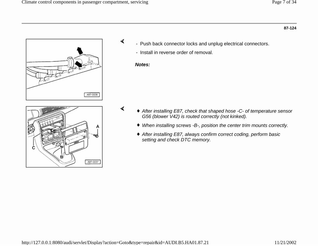
- Push back connector locks and unplug electrical connectors.
- Install in reverse order of removal.
After installing E87, check that shaped hose -C- of temperature sensor G56 (blower V42) is routed correctly (not kinked).
When installing screws -B-, position the center trim mounts correctly.
After installing E87, always confirm correct coding, perform basic setting and check DTC memory.
Page 7 of 34Climate control components in passenger compartment, servicing
11/21/2002http://127.0.0.1:8080/audi/servlet/Display?action=Goto&type=repair&id=AUDI.B5.HA01.87.21

87-125
Removing and installing (A/C control head with single display)
Removing
CAUTION!
Obtain security code for anti-theft radio.
Note customer's pre-set radio stations.
Disconnect battery Ground (GND) strap.
Remove radio or radion with navigation system
Repair Manual, Radio, Telephone, Navigation, Repair Group 91
- Grip control head through radio opening and slide rearward.
Notes:
Parts catalog
The control head is held in the center console with 4 clips -A-.
Before replacing the control head, ensure correct application (e.g. with or without knockouts for switches for seat heaters)
Page 8 of 34Climate control components in passenger compartment, servicing
11/21/2002http://127.0.0.1:8080/audi/servlet/Display?action=Goto&type=repair&id=AUDI.B5.HA01.87.21

Press seat heater switches -C- back into control head so that latches -B- are engaged.
Make sure that the hose for the instrument panel interior temperature sensor -G56- is not kinked or otherwise closed off.
Page 9 of 34Climate control components in passenger compartment, servicing
11/21/2002http://127.0.0.1:8080/audi/servlet/Display?action=Goto&type=repair&id=AUDI.B5.HA01.87.21
87-126
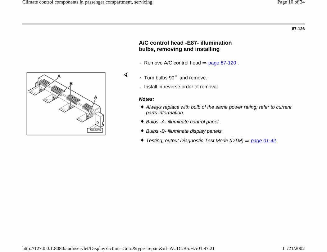
A/C control head -E87- illumination bulbs, removing and installing
- Remove A/C control head page 87-120 .
Notes:
- Turn bulbs 90 and remove.
- Install in reverse order of removal.
Always replace with bulb of the same power rating; refer to current parts information.
Bulbs -A- illuminate control panel.
Bulbs -B- illuminate display panels.
Testing, output Diagnostic Test Mode (DTM) page 01-42 .
Page 10 of 34Climate control components in passenger compartment, servicing
11/21/2002http://127.0.0.1:8080/audi/servlet/Display?action=Goto&type=repair&id=AUDI.B5.HA01.87.21
87-127
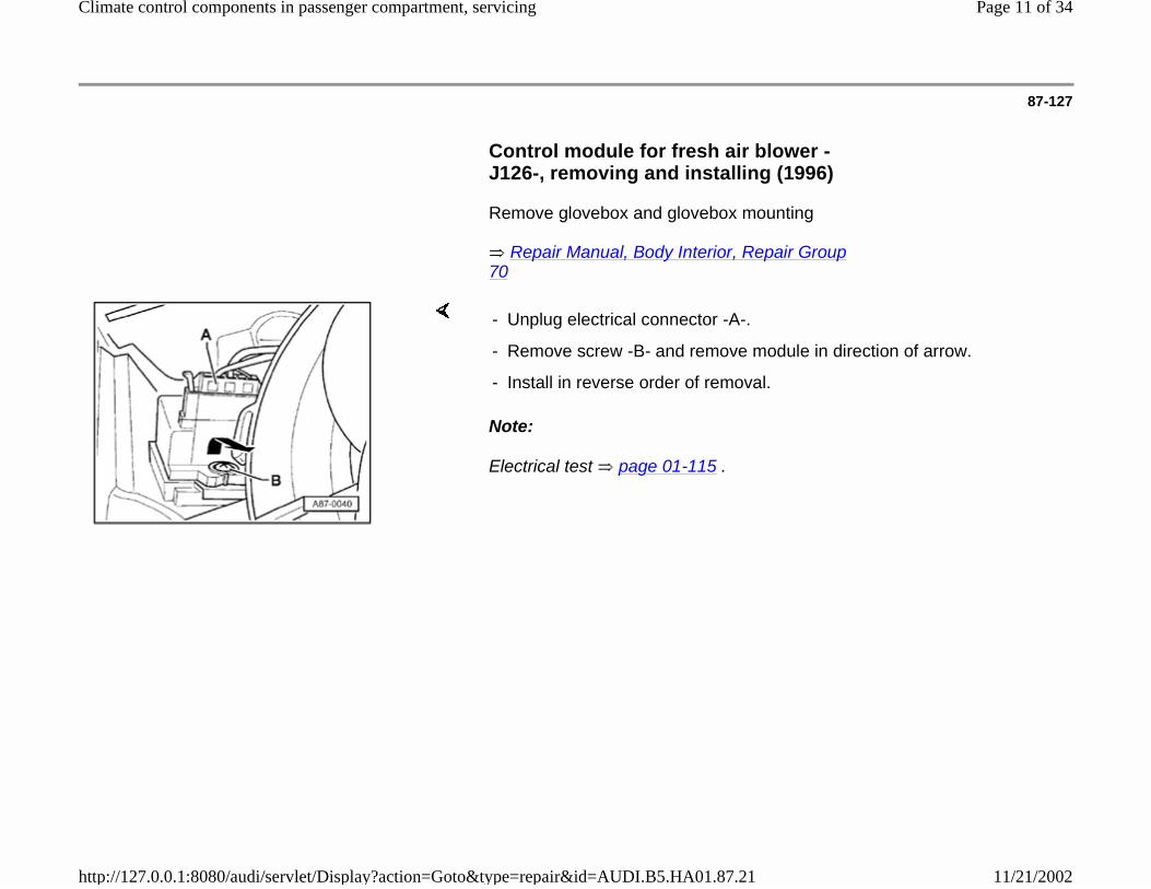
Control module for fresh air blower -J126-, removing and installing (1996)
Remove glovebox and glovebox mounting
Repair Manual, Body Interior, Repair Group 70
Note:
Electrical test page 01-115 .
- Unplug electrical connector -A-.
- Remove screw -B- and remove module in direction of arrow.
- Install in reverse order of removal.
Page 11 of 34Climate control components in passenger compartment, servicing
11/21/2002http://127.0.0.1:8080/audi/servlet/Display?action=Goto&type=repair&id=AUDI.B5.HA01.87.21
87-128
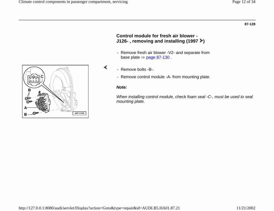
Control module for fresh air blower -J126- , removing and installing (1997 )
- Remove fresh air blower -V2- and separate from base plate page 87-130 .
Note:
When installing control module, check foam seal -C-, must be used to seal mounting plate.
- Remove bolts -B-.
- Remove control module -A- from mounting plate.
Page 12 of 34Climate control components in passenger compartment, servicing
11/21/2002http://127.0.0.1:8080/audi/servlet/Display?action=Goto&type=repair&id=AUDI.B5.HA01.87.21

87-129
Fresh air blower (V2), removing and installing (1996)
Remove glovebox, glovebox mounting and mounting for passenger airbag
Repair Manual, Body Interior, Repair Group 70
Notes:
- Remove 4 screws -A- and remove fresh air blower from heater/air conditioner assembly.
- Install in reverse order of removal.
The fresh air blower must be turned slightly to allow removal from heater/air conditioner assembly.
Testing V2, output Diagnostic Test Mode (DTM) page 01-42 .
Electrical test page 01-115 .
Page 13 of 34Climate control components in passenger compartment, servicing
11/21/2002http://127.0.0.1:8080/audi/servlet/Display?action=Goto&type=repair&id=AUDI.B5.HA01.87.21

87-130
Fresh air blower -V2-, removing and installing (1997 )
Remove glovebox
Repair Manual, Body Interior, Repair Group 70
Separating fresh air blower -V2- and mounting plate
- Remove electrical connector -B-
- Remove bolts -A- and remove fresh air blower with mounting plate from heater/air conditioner assembly.
- Depress locking tabs -A- and -B- with screwdriver.
- Separate fresh air blower from mounting plate.
- Disconnect electrical harness connectors -C-.
Page 14 of 34Climate control components in passenger compartment, servicing
11/21/2002http://127.0.0.1:8080/audi/servlet/Display?action=Goto&type=repair&id=AUDI.B5.HA01.87.21

87-131
Notes:
When re-installing the fresh air blower to the mounting plate, check for correct installation position of tabs -A- and -B-.
After installation check for correct fit or fresh air blower in heater/air conditioner assembly.
Page 15 of 34Climate control components in passenger compartment, servicing
11/21/2002http://127.0.0.1:8080/audi/servlet/Display?action=Goto&type=repair&id=AUDI.B5.HA01.87.21

87-132
Sensor for outlet temperature, center -G191-, removing and installing (1997 )
Remove Radio
Repair Manual, Radio, Telephone, Navigation, Repair Group 91
Remove trim for instrument panel center part
Repair Manual, Body Interior, Repair Group 70
- Disconnect electrical connector -A-.
- Turn sensor -B- 90 and remove.
Page 16 of 34Climate control components in passenger compartment, servicing
11/21/2002http://127.0.0.1:8080/audi/servlet/Display?action=Goto&type=repair&id=AUDI.B5.HA01.87.21

87-133
Sensor for outlet temperature, center -G192-, removing and installing (1997 )
Remove driver side under-dash panel
Repair Manual, Body Interior, Repair Group 70
- Disconnect electrical connector -A-.
- Turn sensor -B- 90 and remove.
Page 17 of 34Climate control components in passenger compartment, servicing
11/21/2002http://127.0.0.1:8080/audi/servlet/Display?action=Goto&type=repair&id=AUDI.B5.HA01.87.21
87-134
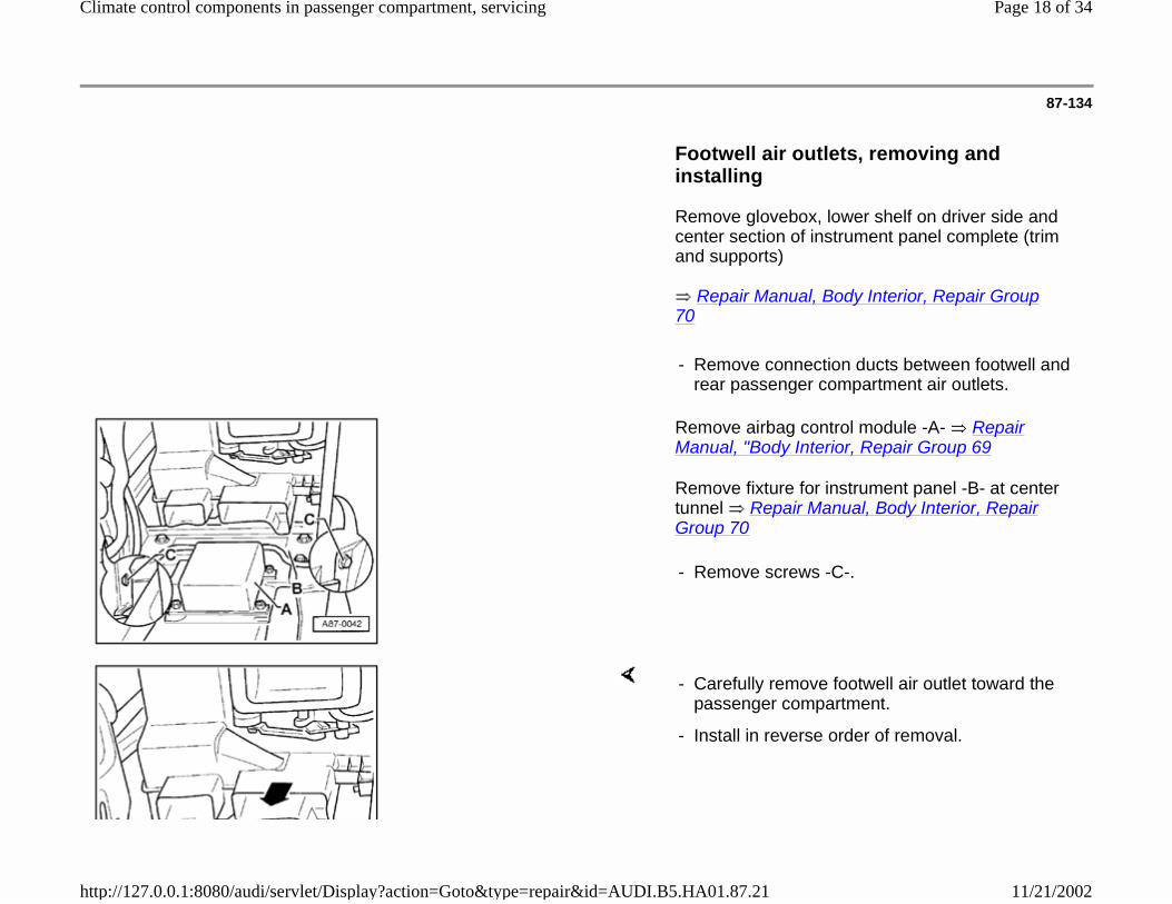
Footwell air outlets, removing and installing
Remove glovebox, lower shelf on driver side and center section of instrument panel complete (trim and supports)
Repair Manual, Body Interior, Repair Group 70
- Remove connection ducts between footwell and rear passenger compartment air outlets.
Remove airbag control module -A- Repair Manual, "Body Interior, Repair Group 69
Remove fixture for instrument panel -B- at center tunnel Repair Manual, Body Interior, Repair Group 70
- Remove screws -C-.
- Carefully remove footwell air outlet toward the passenger compartment.
- Install in reverse order of removal.
Page 18 of 34Climate control components in passenger compartment, servicing
11/21/2002http://127.0.0.1:8080/audi/servlet/Display?action=Goto&type=repair&id=AUDI.B5.HA01.87.21
87-135
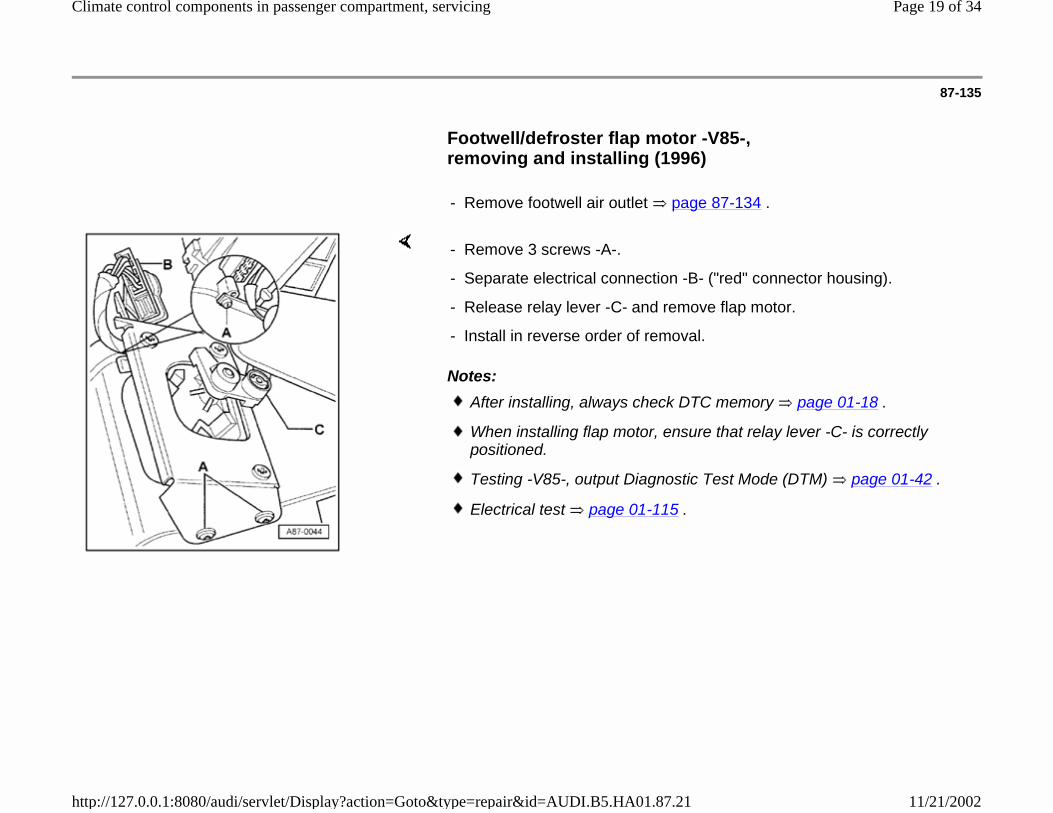
Footwell/defroster flap motor -V85-, removing and installing (1996)
- Remove footwell air outlet page 87-134 .
Notes:
- Remove 3 screws -A-.
- Separate electrical connection -B- ("red" connector housing).
- Release relay lever -C- and remove flap motor.
- Install in reverse order of removal.
After installing, always check DTC memory page 01-18 .
When installing flap motor, ensure that relay lever -C- is correctly positioned.
Testing -V85-, output Diagnostic Test Mode (DTM) page 01-42 .
Electrical test page 01-115 .
Page 19 of 34Climate control components in passenger compartment, servicing
11/21/2002http://127.0.0.1:8080/audi/servlet/Display?action=Goto&type=repair&id=AUDI.B5.HA01.87.21

87-136
Footwell/defroster flap motor -V85-, removing and installing (1997 )
Remove driver side under dash panel
Repair Manual, Body Interior, Repair Group 70
- Remove bolts -A- and -B- (for left instrument panel support).
- Remove floor outlet page 87-134 .
- Disconnect electrical connector from motor.
- Remove bolt -A-.
- Unhook lower strap -B- of bracket with screw driver -C-.
- Remove motor and unhook lever -D- (color: white).
Page 20 of 34Climate control components in passenger compartment, servicing
11/21/2002http://127.0.0.1:8080/audi/servlet/Display?action=Goto&type=repair&id=AUDI.B5.HA01.87.21
87-137
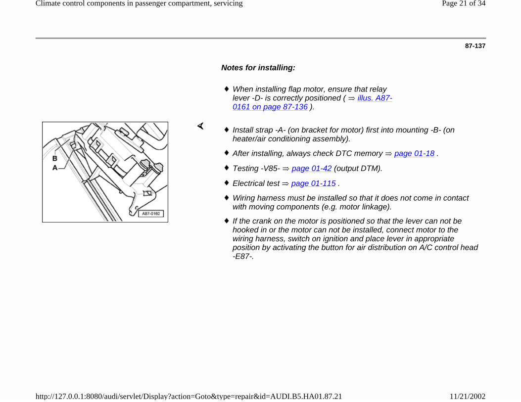
Notes for installing:
When installing flap motor, ensure that relay lever -D- is correctly positioned ( illus. A87-0161 on page 87-136 ).
Install strap -A- (on bracket for motor) first into mounting -B- (on heater/air conditioning assembly).
After installing, always check DTC memory page 01-18 .
Testing -V85- page 01-42 (output DTM).
Electrical test page 01-115 .
Wiring harness must be installed so that it does not come in contact with moving components (e.g. motor linkage).
If the crank on the motor is positioned so that the lever can not be hooked in or the motor can not be installed, connect motor to the wiring harness, switch on ignition and place lever in appropriate position by activating the button for air distribution on A/C control head -E87-.
Page 21 of 34Climate control components in passenger compartment, servicing
11/21/2002http://127.0.0.1:8080/audi/servlet/Display?action=Goto&type=repair&id=AUDI.B5.HA01.87.21

87-138
Temperature regulator flap motor -V68-, removing and installing (1996)
- Remove footwell air outlet page 87-134 .
Notes:
- Remove 3 screws -A-.
- Separate electrical connection to flap motor ("black" connector housing).
- Release relay lever -B- and remove flap motor.
- Install in reverse order of removal.
After installing, always check DTC memory page 01-18 .
When installing flap motor, ensure that relay lever -B- is correctly positioned.
Testing -V68-, output Diagnostic Test Mode (DTM) page 01-42 .
Electrical test page 01-115 .
Page 22 of 34Climate control components in passenger compartment, servicing
11/21/2002http://127.0.0.1:8080/audi/servlet/Display?action=Goto&type=repair&id=AUDI.B5.HA01.87.21
87-139
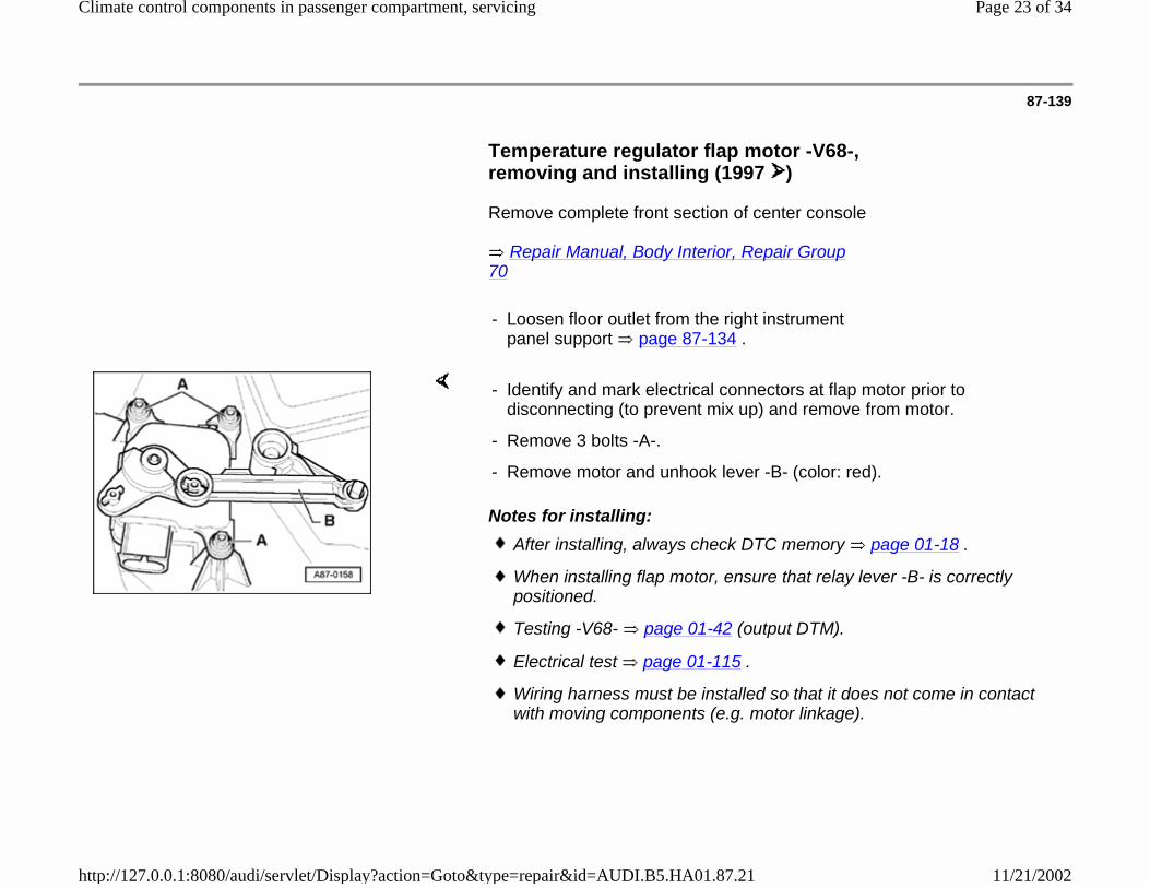
Temperature regulator flap motor -V68-, removing and installing (1997 )
Remove complete front section of center console
Repair Manual, Body Interior, Repair Group 70
- Loosen floor outlet from the right instrument panel support page 87-134 .
Notes for installing:
- Identify and mark electrical connectors at flap motor prior to disconnecting (to prevent mix up) and remove from motor.
- Remove 3 bolts -A-.
- Remove motor and unhook lever -B- (color: red).
After installing, always check DTC memory page 01-18 .
When installing flap motor, ensure that relay lever -B- is correctly positioned.
Testing -V68- page 01-42 (output DTM).
Electrical test page 01-115 .
Wiring harness must be installed so that it does not come in contact with moving components (e.g. motor linkage).
Page 23 of 34Climate control components in passenger compartment, servicing
11/21/2002http://127.0.0.1:8080/audi/servlet/Display?action=Goto&type=repair&id=AUDI.B5.HA01.87.21
87-140
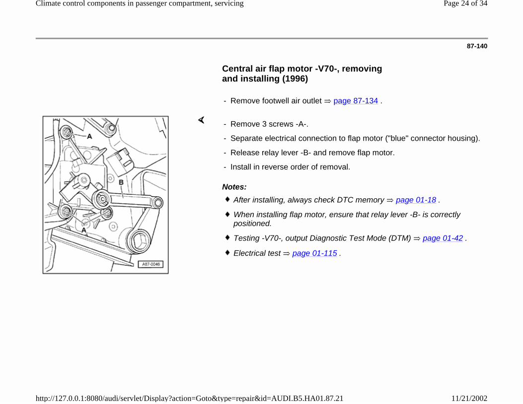
Central air flap motor -V70-, removing and installing (1996)
- Remove footwell air outlet page 87-134 .
Notes:
- Remove 3 screws -A-.
- Separate electrical connection to flap motor ("blue" connector housing).
- Release relay lever -B- and remove flap motor.
- Install in reverse order of removal.
After installing, always check DTC memory page 01-18 .
When installing flap motor, ensure that relay lever -B- is correctly positioned.
Testing -V70-, output Diagnostic Test Mode (DTM) page 01-42 .
Electrical test page 01-115 .
Page 24 of 34Climate control components in passenger compartment, servicing
11/21/2002http://127.0.0.1:8080/audi/servlet/Display?action=Goto&type=repair&id=AUDI.B5.HA01.87.21

87-141
Central air flap motor -V70-, removing and installing (1997 )
Remove complete front section of center console
Repair Manual, Body Interior, Repair Group 70
- Loosen floor outlet from the right instrument panel support page 87-134 .
Notes for installing:
- Identify and mark electrical connectors at flap motor prior to disconnecting (to prevent mix up) and remove from motor.
- Remove 3 bolts -A-.
- Remove motor and unhook lever -B- (color: blue).
After installing, always check DTC memory page 01-18 .
When installing flap motor, ensure that relay lever -B- is correctly positioned.
Testing -V70- page 01-42 (output DTM).
Electrical test page 01-115 .
Wiring harness must be installed so that it does not come in contact with moving components (e.g. motor linkage).
Page 25 of 34Climate control components in passenger compartment, servicing
11/21/2002http://127.0.0.1:8080/audi/servlet/Display?action=Goto&type=repair&id=AUDI.B5.HA01.87.21

87-142
Fresh air/recirculating flap two-way valve -N63-, removing and installing
Remove glovebox
Repair Manual, Body Interior, Repair Group 70
Notes:
- Remove bolt -A-.
- Separate electrical connection.
- Install in reverse order of removal.
Connect vacuum hoses correctly (hose -B- to vacuum reservoir, hose -C- to vacuum unit).
Vacuum hose layout page 87-184 .
Testing -N63-, output Diagnostic Test Mode (DTM) page 01-42 .
Electrical test page 01-115 .
Page 26 of 34Climate control components in passenger compartment, servicing
11/21/2002http://127.0.0.1:8080/audi/servlet/Display?action=Goto&type=repair&id=AUDI.B5.HA01.87.21

87-143
Instrument panel interior temperature sensor -G56-, removing and installing
Remove radio and center section of instrument panel complete (trim and supports)
Repair Manual, Radio, Telephone, Navigation, Repair Group 91 and
Repair Manual, Body Interior, Repair Group 70
Notes:
Check temperature sensor intake -A- and intake hose -C-; air flow must not be restricted by dust or debris.
Temperature sensor -B- is attached to switch mounting; replace complete unit.
Electrical test page 01-115 .
Page 27 of 34Climate control components in passenger compartment, servicing
11/21/2002http://127.0.0.1:8080/audi/servlet/Display?action=Goto&type=repair&id=AUDI.B5.HA01.87.21

87-144
Sunlight photo sensor -G107-, removing and installing
Note:
Testing -G107- page 01-63 .
- Carefully pry off cover -A-.
- Remove screw -B-.
- Remove sensor.
- Separate electrical connection.
- Install in reverse order of removal.
Page 28 of 34Climate control components in passenger compartment, servicing
11/21/2002http://127.0.0.1:8080/audi/servlet/Display?action=Goto&type=repair&id=AUDI.B5.HA01.87.21
87-145
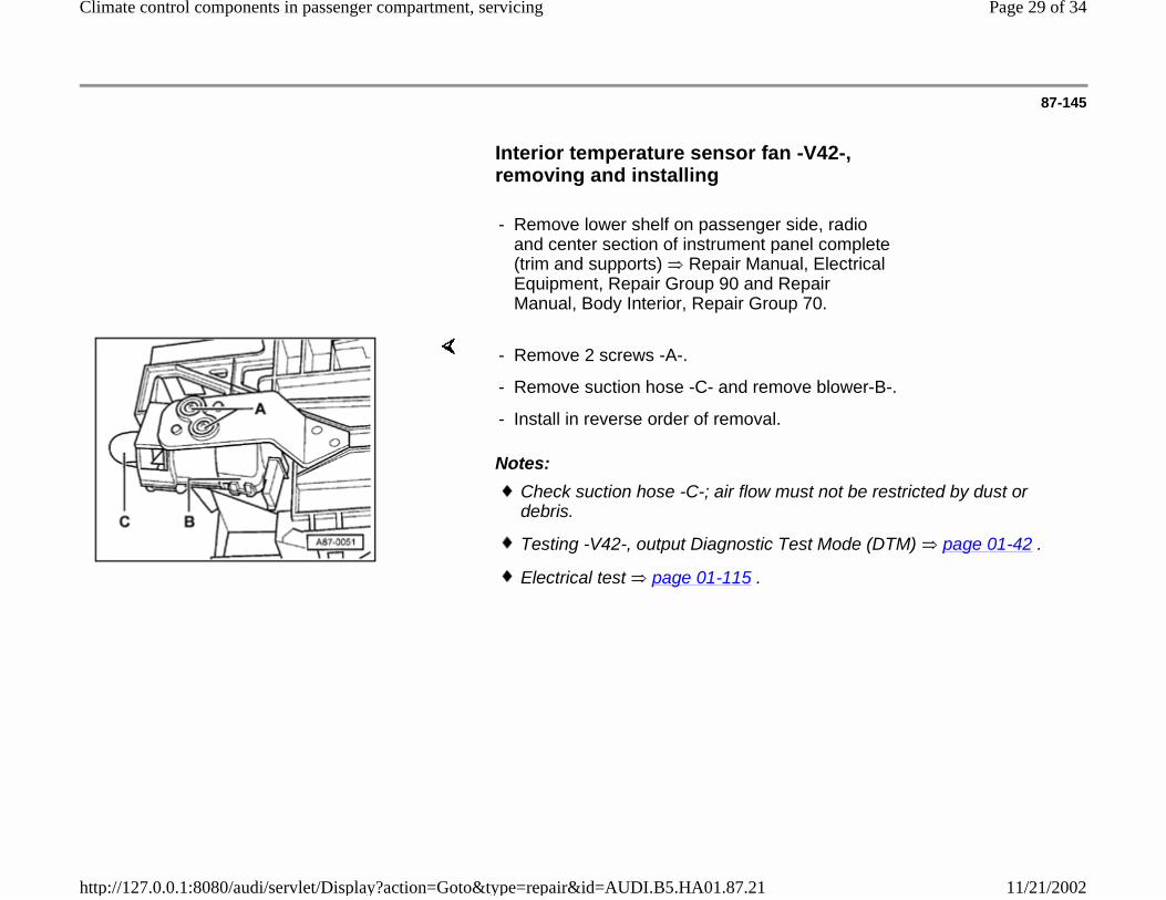
Interior temperature sensor fan -V42-, removing and installing
- Remove lower shelf on passenger side, radio and center section of instrument panel complete (trim and supports) Repair Manual, Electrical Equipment, Repair Group 90 and Repair Manual, Body Interior, Repair Group 70.
Notes:
- Remove 2 screws -A-.
- Remove suction hose -C- and remove blower-B-.
- Install in reverse order of removal.
Check suction hose -C-; air flow must not be restricted by dust or debris.
Testing -V42-, output Diagnostic Test Mode (DTM) page 01-42 .
Electrical test page 01-115 .
Page 29 of 34Climate control components in passenger compartment, servicing
11/21/2002http://127.0.0.1:8080/audi/servlet/Display?action=Goto&type=repair&id=AUDI.B5.HA01.87.21

87-146
Air flow flap motor -V71-, removing and installing (1996)
- Remove heater/air conditioner assembly complete with instrument panel page 87-159 .
Notes:
- Remove 3 screws -A- and remove flap motor.
- Install in reverse order of removal noting the following.
Markings on the gears of flap motor -B- and air flow flap -C- must be aligned (longer tooth and continuous tooth intermediate space).
If lever of flap motor rests against stop D, the intake shaft through the air flow flap must be closed when the flap motor is installed (longer side of air flow flap faces in direction of travel).
After installing, check DTC memory page 01-18 .
Testing V71, output Diagnostic Test Mode (DTM) page 01-42 .
Electrical test page 01-115 .
Page 30 of 34Climate control components in passenger compartment, servicing
11/21/2002http://127.0.0.1:8080/audi/servlet/Display?action=Goto&type=repair&id=AUDI.B5.HA01.87.21
87-147
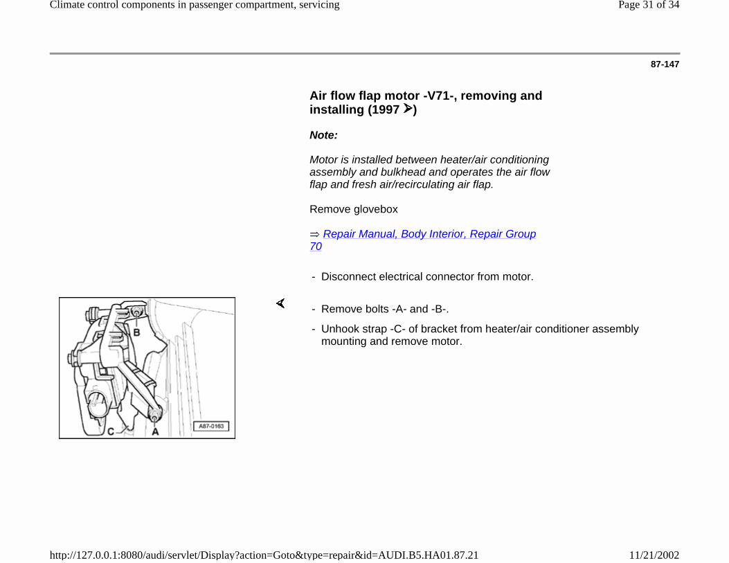
Air flow flap motor -V71-, removing and installing (1997 )
Note:
Motor is installed between heater/air conditioning assembly and bulkhead and operates the air flow flap and fresh air/recirculating air flap.
Remove glovebox
Repair Manual, Body Interior, Repair Group 70
- Disconnect electrical connector from motor.
- Remove bolts -A- and -B-.
- Unhook strap -C- of bracket from heater/air conditioner assembly mounting and remove motor.
Page 31 of 34Climate control components in passenger compartment, servicing
11/21/2002http://127.0.0.1:8080/audi/servlet/Display?action=Goto&type=repair&id=AUDI.B5.HA01.87.21

87-148
Notes for installing:
After installing, always check DTC memory page 01-18 .
Testing -V71- page 01-42 (output DTM).
Electrical test page 01-115 .
Wiring harness must be installed so that it does not come in contact with moving components (Eg.: motor linkage).
Metal lever -A- moves the air flow flap and is inserted in the closed guide groove -C-.
Plastic lever -B- moves the fresh air/recirculating air flap, runs mostly on the rear of the curved disc and only assumes an open guide groove position when in "recirculating operation."
Page 32 of 34Climate control components in passenger compartment, servicing
11/21/2002http://127.0.0.1:8080/audi/servlet/Display?action=Goto&type=repair&id=AUDI.B5.HA01.87.21

87-149
Fresh air intake duct temperature sensor -G89-, removing and installing (1996)
- Remove heater/air conditioner assembly complete with instrument panel page 87-159 .
Notes:
- Turn temperature sensor -A- 90 to remove.
- Install in reverse order of removal.
Testing -G89- page 01-63 .
Electrical test page 01-115 .
Page 33 of 34Climate control components in passenger compartment, servicing
11/21/2002http://127.0.0.1:8080/audi/servlet/Display?action=Goto&type=repair&id=AUDI.B5.HA01.87.21
87-150
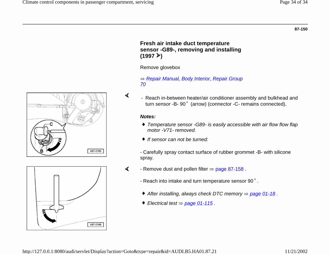
Fresh air intake duct temperature sensor -G89-, removing and installing (1997 )
Remove glovebox
Repair Manual, Body Interior, Repair Group 70
Notes:
- Carefully spray contact surface of rubber grommet -B- with silicone spray.
- Reach in-between heater/air conditioner assembly and bulkhead and turn sensor -B- 90 (arrow) (connector -C- remains connected).
Temperature sensor -G89- is easily accessible with air flow flow flap motor -V71- removed.
If sensor can not be turned:
- Remove dust and pollen filter page 87-158 .
- Reach into intake and turn temperature sensor 90 .
After installing, always check DTC memory page 01-18 .
Electrical test page 01-115 .
Page 34 of 34Climate control components in passenger compartment, servicing
11/21/2002http://127.0.0.1:8080/audi/servlet/Display?action=Goto&type=repair&id=AUDI.B5.HA01.87.21