servicing instructions halstead best db for … · contents introduction1 the halstead best db...
TRANSCRIPT

Best 30 G. C. No. 41 333 50 EC 0087/AT/5342 Best 40 G. C. No. 41 333 51Best 50 G. C. No. 41 333 52Best 60 G. C. No. 41 333 53 SUPPLY PRESSURE 20 mbar
0 0 8 6
TO BE LEFT WITH THE USER
FOR USE WITH NATURAL GAS ONLY (G20)
CAST IRON
WALL MOUNTED
FAN ASSISTED BOILER
BR
IT
IS
HM
AD
EB
OI
LE
RSINSTALLATION &
SERVICING INSTRUCTIONS FOR THE HALSTEAD
30/40/50/6030/40/50/60
HALSTEADBest dbBest db

CONTENTS INTRODUCTION1The Halstead Best db 30,40,50 and 60 are wall mounted,fan assisted balanced flue natural gas boilers incorporating acast iron heat exchanger. The appliance incorporates automaticdirect burner ignition and electronic temperature control. Itfeatures an attractive white enamelled casing with a removablefront panel which when removed enables the appliance to befitted within a standard kitchen wall unit. (Remove top andbottom panels of kitchen unit). The appliances are supplied with a standard concentric air andflue duct suitable for flue lengths of up to 820mm (32in). Theduct assembly is connected to the boiler via an elbow which canexit the appliance in any horizontal direction. Additional flue kitsare available to extend the flue length up to a maximum of3.121m (123in), and further kits are available to provide up totwo bends in the flue, although the maximum length must bereduced (as detailed in these instructions) to accommodate extra bends. A vertical outlet kit is also available for installations where anoutside wall is not accessible and it is required to fit the duct"through the roof". Installation using the standard flue kit (with orwithout straight extensions) is described in the main text of theseinstructions. This booklet describes installations involving raisedflue systems, extra elbows, and the vertical outlet kit. The appliance can be installed from inside the room withoutaccess to the external wall providing that a wall liner is fitted andthe wall thickness is less than 0.5m (19in). The wall liner isavailable as an optional extra. See Section 4 for further details.(Note: If the vertical outlet kit is to be used, access to the roof isnecessary). These appliances are most suitable for fully pumped, openvented or sealed systems, but may be used on an open ventsystem utilising gravity domestic hot water and pumped centralheating Fully Pumped: If thermostatic radiator valves are fitted it isrecommended that a bypass is installed to provide a suitablewater circuit should all the thermostatic radiator valves be shut.This bypass circuit should incorporate a minimum volume of 7 litres. It may utilise one radiator which should be fitted withlockshield valves only. Gravity: It is recommended that when used on a gravitydomestic hot water application a Honeywell "C Plus" plan orequivalent is fitted to the system to give suitable control over thedomestic hot water temperature. The cylinder thermostat shouldbe set NO higher than 60°C. The Honeywell "C Plus" will allowthe pump overun to operate (should it be necessary) withoutwarming the radiators when the domestic hot water only is on.The bypass should have a water volume, (7 litres minimum) butshould NOT incorporate any radiators. The flow sensingtemperature is limited to 60°C in the gravity mode, when the CHpump is off. This is to prevent the cylinder of DHW fromoverheating.
Page1 INTRODUCTION . . . . . . . . . . . . . . . . . . . . . . . . . . . . . . 1
2 TECHNICAL SPECIFICATIONS . . . . . . . . . . . . . . . . . . . . . 12.1 Performance data . . . . . . . . . . . . . . . . . . . . . . . . . . . . . . . . . 12.2 Connection sizes. . . . . . . . . . . . . . . . . . . . . . . . . . . . . . . . . . 12.3 General data . . . . . . . . . . . . . . . . . . . . . . . . . . . . . . . . . . . . 12.4 Minimum clearance and overall dimensions . . . . . . . . . . . . . . 12.5 Air/flue duct specifications . . . . . . . . . . . . . . . . . . . . . . . . . . . 22.6 Exploded diagram . . . . . . . . . . . . . . . . . . . . . . . . . . . . . . . . 6
3 INSTALLATION REQUIREMENTS . . . . . . . . . . . . . . . . . . . 73.1 Statutory requirements. . . . . . . . . . . . . . . . . . . . . . . . . . . . . . 73.2 Boiler location . . . . . . . . . . . . . . . . . . . . . . . . . . . . . . . . . . . 73.3 Flue terminal position . . . . . . . . . . . . . . . . . . . . . . . . . . . . . . 83.4 Ventilation requirements . . . . . . . . . . . . . . . . . . . . . . . . . . . . 83.5 Gas supply . . . . . . . . . . . . . . . . . . . . . . . . . . . . . . . . . . . . . 83.6 Electrical supply . . . . . . . . . . . . . . . . . . . . . . . . . . . . . . . . . . 83.7 Water systems . . . . . . . . . . . . . . . . . . . . . . . . . . . . . . . . . . . 8
4 INSTALLING THE APPLIANCE . . . . . . . . . . . . . . . . . . . . 114.1 Unpacking the appliance. . . . . . . . . . . . . . . . . . . . . . . . . . . 114.2 Preparing the wall. . . . . . . . . . . . . . . . . . . . . . . . . . . . . . . . 114.3 Preparing the appliance . . . . . . . . . . . . . . . . . . . . . . . . . . . 124.4 Mounting the appliance. . . . . . . . . . . . . . . . . . . . . . . . . . . . 124.5 Flue/air duct installation . . . . . . . . . . . . . . . . . . . . . . . . . . . 124.6 Gas connection . . . . . . . . . . . . . . . . . . . . . . . . . . . . . . . . . 154.7 Water connections . . . . . . . . . . . . . . . . . . . . . . . . . . . . . . . 154.8 Wiring instructions . . . . . . . . . . . . . . . . . . . . . . . . . . . . . . . 15
5 COMMISSIONING & TESTING . . . . . . . . . . . . . . . . . . . 185.1 Open vented water systems . . . . . . . . . . . . . . . . . . . . . . . . 185.2 Sealed water systems . . . . . . . . . . . . . . . . . . . . . . . . . . . . . 185.3 User instructions . . . . . . . . . . . . . . . . . . . . . . . . . . . . . . . . 18
6 ROUTINE SERVICING . . . . . . . . . . . . . . . . . . . . . . . . . . 196.1 Main burner assembly. . . . . . . . . . . . . . . . . . . . . . . . . . . . . 196.2 Fan assembly . . . . . . . . . . . . . . . . . . . . . . . . . . . . . . . . . . . 196.3 Heat exchanger . . . . . . . . . . . . . . . . . . . . . . . . . . . . . . . . . 196.4 Re-assemble and re-commission . . . . . . . . . . . . . . . . . . . . . 19
7 PARTS REPLACEMENT. . . . . . . . . . . . . . . . . . . . . . . . . . 207.1 Overheat cut off device . . . . . . . . . . . . . . . . . . . . . . . . . . . . 207.2 Flow temperature thermistor . . . . . . . . . . . . . . . . . . . . . . . . 207.3 Air pressure switch . . . . . . . . . . . . . . . . . . . . . . . . . . . . . . . 207.4 Ignition PCB (fully enclosed). . . . . . . . . . . . . . . . . . . . . . . . . 207.5 Aquastat PCB & Housing . . . . . . . . . . . . . . . . . . . . . . . . . . . 207.6 Potentiometer . . . . . . . . . . . . . . . . . . . . . . . . . . . . . . . . . . . 217.7 Main burner injector . . . . . . . . . . . . . . . . . . . . . . . . . . . . . . 217.8 Gas valve . . . . . . . . . . . . . . . . . . . . . . . . . . . . . . . . . . . . . 217.9 Main burner. . . . . . . . . . . . . . . . . . . . . . . . . . . . . . . . . . . . 217.10 Ignition electrode (front left hand of burner). . . . . . . . . . . . . . 217.11 Flame sensing electrode (rear left of burner) . . . . . . . . . . . . . 217.12 Fan assembly . . . . . . . . . . . . . . . . . . . . . . . . . . . . . . . . . . . 227.13 Combustion chamber insulation . . . . . . . . . . . . . . . . . . . . . . 22
8 INTERNAL WIRING DIAGRAMS . . . . . . . . . . . . . . . . . . 228.1 Functional flow wiring diagram . . . . . . . . . . . . . . . . . . . . . . 228.2 Illustrated wiring diagram . . . . . . . . . . . . . . . . . . . . . . . . . . 22
9 FAULT FINDING. . . . . . . . . . . . . . . . . . . . . . . . . . . . . . 23
10 SHORT PARTS LIST. . . . . . . . . . . . . . . . . . . . . . . . . . . . 24
11 Supplementary instructions for Flue systems with vertical terminals . . . . . . . . . . . . . . . . . . . . . . . . . . . . . . . . 25
12 Supplementary instructions for Flue systems incorporating anadditional 90° elbow. . . . . . . . . . . . . . . . . . . . . . . . . . . . . . 25SE-DUCT Applications . . . . . . . . . . . . . . . . . . . . . . . . . . . . . 25

1
TECHNICAL SPECIFICATIONS2BEST 30/40/50/60
2.1 PERFORMANCE DATA
HeatOutput
1
Gas Connection Rc 0.5in (1/2in BSP female)
Gravity Water Connections 2x28mm copper compressionPumped Water Connections 2x22mm copper compression
CONNECTION SIZES
2.3 GENERAL SPECIFICATIONS
2.2
OVERALL DIMENSIONS AND MINIMUM CLEARANCES2.4
Max.
Min.
Max.
Min.
Max.
Min.
Max.
Min.
HeatInputGross
BurnerPressure
Note: A door may be fittedwithin 6mm of the frontcasing provided that it isremoveable and there is300mm (12”) clearence forservicing.The front case may beremoved to enable the boilerto be installed within astandard wall unit, minimumclearance required 6mm(0.25in)
6mm
100mm
SEENOTE
6mm
200mm
66mm
FLOW
RETURN
30mm
62mm
28mm Dia.
22mm Dia.
600mm
400mm
28mm Dia.
22mm Dia.
305mm withfront panel
691mm
290mm tocontrol knob
165mm
GAS COCK
380mm
218mm
82mm
206mm
276mm withoutfront panel
1(a) 1(c)
1(b)
kw 8.79 11.72 14.65 17.58Btu/hr 30000 40000 50000 60000kw 5.86 8.79 11.72Btu/hr 20000 30000 40000 60000kw 11.13 14.75 18.43 22.37Btu/hr 37975 50315 62893 76326kw 7.71 11.42 14.84Btu/hr 26316 38950 50633kw 10.02 13.28 16.59 20.14Btu/hr 34188 45311 56605 68717kw 6.94 10.28 13.36Btu/hr 23679 35075 45584mbar 14 14.5 14.6 15.5in.wg 5.6 5.8 5.9 6.2mbar 6.9 8.4 9.4in.wg 2.8 3.4 3.8
Best 30 40 50 60
HeatInputNett
Main Burner
Injector mm (in) Dia. 2.61(0.102) 3.03(0.12) 3.39(0.13) 3.61(0.14)
Minimum Water Flow Rate
l/min (galls/min) 11.45(2.51) 15.27(3.35) 19.09(4.18) 22.9(5.02)
Total Water Capacity litres (galls) 3(0.66) 3(0.66) 3(0.66) 3(0.66)
Pressure Loss at 11°C (20°F)
Temp. Diff. mH2O 0.42 0.73 1.13 1.68
Static Head
Maximum metres (ft) 30 (100) 30 (100) 30 (100) 30 (100)
Static Head
Minimum metres (ft) 1.2 (3.9) 1.2 (3.9) 1.2 (3.9) 1.2 (3.9)
Weight
Empty kg (lb) 42 (92.5) 42 (92.5) 42 (92.5) 42 (92.5)
Lift Weight kg (lb) 36 (79.3) 36 (79.3) 36 (79.3) 36 (79.3)
Electricity Supply 230V-50Hz 230V-50Hz 230V-50Hz 230V-50Hz
Power Consumption Watts 35 35 35 35
External Fuse Amps 3 3 3 3
Gas Consumption
l/min (ft3/hr) 17.68(37.4) 23.42(49.5) 29.27(61.9) 35.35(74.7)
30 40 50 60

2
2 EXAMPLES OF ALTERNATIVE FLUE SYSTEMS
•STANDARDTELESCOPICFLUE
•FLANGED ELBOW
2(a) HORIZONTALSTRAIGHT FLUESUPPLIED AS STANDARD
•
•
•
•
•
FLANGED ELBOW
STANDARDDUCT
EXTENSION DUCT
EXTENSION DUCT
2(b) HORIZONTAL STRAIGHT FLUE
• TERMINAL DUCT
• EXTENSION DUCT
• 90º ELBOWNON-FLANGED
• STANDARD DUCT
•
VERTICALSOCKET
2(c) ELEVATEDSTRAIGHT FLUE3 COMPONENTSAS SHOWN
•
TERMINAL DUCT
•
EXTENSION DUCT
•
VERTICAL SOCKET
•90º ELBOWNON-FLANGED
•STANDARDDUCT
•
90º ELBOWNON-FLANGED
•EXTENSION DUCT
2(d) FLUE WITH 90° BEND
•TERMINAL
DUCT
•STANDARD DUCT
•
FLANGED ELBOW
•
90º ELBOWNON-FLANGED
• •
EXTENSIONDUCTS
2(e) HORIZONTALFLUE WITH 90° BEND
2(f) VERTICALSTRAIGHT FLUE
•
VERTICALCOWL
• EXTENSIONDUCT
• EXTENSIONDUCT
• EXTENSIONDUCT
•
STANDARDDUCT
•
VERTICALSOCKET
2(g) OFFSETVERTICAL FLUE
•
•
EXTENSIONDUCTS
• 90º ELBOWNON-FLANGED
•
FLANGEDELBOW
•
STANDARDDUCT
EXITS APPLIANCEAT REAR OREITHER SIDE
2(h) TYPICAL VERTICALINSTALLATION USING45° ELBOWS •VERTICAL
COWL
•45º ELBOW
•EXTENSIONDUCT
•45º ELBOW
•
STANDARDDUCT
•
VERTICALSOCKET
• VERTICALCOWL
TERMINAL DUCT

3
The appliance is supplied complete with a standard telescopic fluekit. This comprises a standard duct and a terminal duct and canbe used for flue lengths between 506mm and 820mm withoutcutting the ducts.The following additional concentric kits are available as optional extras.Extension duct (each extension extends the flue length by up to767 mm)90° Elbow (Allows an additional bend in the flue and has an‘equivalent length’ of 767mm.) This elbow is mechanicallydifferent from the flanged elbow supplied as standard with theappliance, but has the same equivalent length of 767mm.45° Elbow (Allows an additional bend in the flue and has an‘equivalent length’ of 384mm.) This elbow is mechanicallydifferent from the flanged elbow supplied as standard with theappliance, but has the same equivalent length of 384mm.
2.5 AIR/FLUE DUCT SPECIFICATIONS
3 SPECIFICATION FOR STANDARD AND EXTENDED STRAIGHT FLUES(Refer to section 2.5(b) for maximum allowable lengths)
•• •
‘L’‘L’
Ws Wr3(a)
• •
•
•
••
•‘L’
‘L’
Ws
Wr3(b)
• •
••
Fig 3a - Standard flue assembly usingeither side or rear outlet.Flue length ‘L’ (measured from the boileroutlet centre line to the outside wall face)= max 820mmMaximum wall thickness Wr (Rear outlet) = 620mm maxMaximum wall thickness Ws (either side outlet) = 590mm max.(Allowing for minimum clearance of 5mm)
Fig 3b - Standard flue assembly withoptional straight extensions using eitherside or rear outletRefer to the following table: (Definitions of lengths ‘L’, Wr and Ws are as given in the table below
NUMBER LENGTH Wr WsOF EXTENSION L’’ (REAR) (SIDE)
KITSONE 1587 1387 1357TWO 2354 2154 2124THREE 3121 2921 2891
Socket (for use with elevated horizontal flues and vertical cowls)Vertical Cowl Kit. (For use where an external wall is not available)
These optional kits may be used with the standard flue kit toproduce an extensive range of flue options. Examples areillustrated in Figure 2. Variations upon these illustrations may beused providing that the following rule is strictly obeyed.
a) Please refer to the following diagrams to select your particularflue application, and work out your parts requirement.
b) The maximum permissible allowable length of the flue system is:3812mm (150in) Horizontal terminal4400mm (173in) Vertical terminal
continued on page 5

4
4 SPECIFICATION FOR FLUE SYSTEMS WITH AN EXTRA 90° ELBOW(Refer to section 2.5(b) for maximum allowable lengths)
4(a)•
•
•Lb Lw
4(b)
•
•
•Lb Lw
•
•
•
Lb
Lw
4(c)
Fig 4a - Use of the flanged elbow, oneextension kit, 90° elbow, and standardflue assembly.
Equivalent Length Shownis 3045mm Where ‘Lb’ is 919mmand ‘Lw’ is 820mm
(Lw is measured to the outside wall face.)
Fig 4b - As 4a but with one additionalextension in length ‘Lb’
Equivalent Length Shownis 3812mm Where ‘Lb’ is 1686mmand ‘Lw’ is 820mm
(Lw is measured to the outside wall face.)
Fig 4c - As 4a but with one additionalextension in length ‘Lw’
Equivalent Length Shownis 3812mm Where ‘Lb’ is 919mmand ‘Lw’ is 1587mm
(Lw is measured to the outside wall face.)
5
7 SPECIFICATION FOR VERTICAL FLUE SYSTEMS
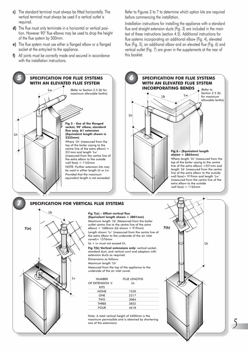
Refer to Figures 3 to 7 to determine which option kits are requiredbefore commencing the installation.Installation instructions for installing the appliance with a standardflue and straight extension ducts (Fig. 3) are included in the maintext of these instructions (section 4.5). Additional instructions forflue systems incorporating an additional elbow (Fig. 4), elevatedflue (Fig. 5), an additional elbow and an elevated flue (Fig. 6) andvertical outlet (Fig. 7) are given in the supplements at the rear ofthis booklet.
5 SPECIFICATION FOR FLUE SYSTEMSWITH AN ELEVATED FLUE SYSTEM
6 SPECIFICATION FOR FLUE SYSTEMSWITH AN ELEVATED FLUE SYSTEMINCORPORATING BENDS
c) The standard terminal must always be fitted horizontally. Thevertical terminal must always be used if a vertical outlet isrequired.
d) The flue must only terminate in a horizontal or vertical posi-tion. However 90° flue elbows may be used to drop the heightof the flue system by 500mm.
e) The flue system must use either a flanged elbow or a flangedsocket at the entry/exit to the appliance.
f) All joints must be correctly made and secured in accordancewith the installation instructions.
•
•Lw
Lh
•
••
•
••
•
Lb
Lh
Lw
7(b)
Lh
•
•
7(a)
Lv
Lb
•
•
•
•
Fig 5 - Use of the flangedsocket, 90° elbow, standardflue assy, &1 extension (Equivalent length shown is2325mm)Where ‘Lh’ (measured from thetop of the boiler casing to thecentre line of the extra elbow) =551mm and length ‘Lw’(measured from the centre line ofthe extra elbow to the outsidewall face) = 1162mm NOTE: Further extension kits maybe used in either length Lh or Lw.Provided that the maximumequivalent length is not exceeded.
(Refer to Section 2.5 (b) formaximum allowable lenths)
Fig 6 - (Equivalent length shown = 3862mm)Where length ‘Lh’ (measured from thetop of the boiler casing to the centreline of the extra elbow) =551mm andlength ‘Lb’ (measured from the centreline of the extra elbow to the outsidewall face)= 919mm and length ‘Lw’(measured from the centre line of theextra elbow to the outside wall face) = 1162mm
(Refer to Section 2.5 (b) for maximumallowable lenths)
Fig 7(a) - Offset vertical flue (Equivalent length shown = 3801mm) Maximum length ‘Lb’ (Measured from the boileroutlet centre line to the centre line of the extraelbow) = 1686mm (Lb shown = 919mm)Length shown ‘Lv’ (measured from the centre line ofthe extra elbow to the underside of the air inletcowel)= 1576mmLb + Lv must not exceed Lh.
Fig 7(b) Vertical extensions only: vertical socket,standard duct, and vertical cowl and adaptors withextension ducts as required.Dimensions as follows:Maximum length ‘Lh’Measured from the top of the appliance to theunderside of the air inlet cowel.
NUMBER FLUE LENGTHSOF EXTENSION ‘L’ Lh
KITSNONE 1550ONE 2317TWO 3084THREE 3852FOUR 4618
Note: A total vertical height of 4400mm is themaximum permissible and is obtained by shorteningone of the extensions.

6
8 EXPLOADED DIAGRAM
Drawing amended 7/05/99
7948
1747
59
12
4
11
7
138
80
5
64
63
81
37
38
39
6043
21
62
77
19
67
68
66
76
78
26
25
56
4919
7175
4965
7346
34 35 366155
28
44
15
23
18
19
22
14
30
31
11
29
3332
4142
4057
50
53 52 54 51
58
70 69 74 72
24

7
INSTALLATION REQUIREMENTS3
The following limitations MUST be observed when sitingthe boiler:a) The boiler is not suitable for external installation. The position
selected for installation should be within the building, unlessotherwise protected by a suitable enclosure, and MUST allowadequate space for installation, servicing, and operation of theappliance, and for air circulation around it. (Section 2.4 and 3.4)
b) This position MUST allow for a suitable flue system andterminal position. (Section 2.5 and 3.3) The boiler must beinstalled on a flat vertical wall which is capable of supportingthe weight of the appliance and any ancillary equipment.
c) If the boiler is to be fitted in a timber framed building itshould be fitted in accordance with the British Gas publication‘Guide for Gas Installations In Timber Frame Housing’,Reference DM2. If in doubt, advice must be sought from theLocal Gas Region.
d) If the appliance is to be installed in a room containing a bathor a shower, any electrical switch or control utilising mainselectricity must be so situated that it cannot be touched by aperson using the bath or shower. Attention is drawn to therequirements of the current I.E.E. Wiring Regulations, and inScotland the electrical provisions of the Building Regulationsapplicable in Scotland.
e) A compartment used to enclose the appliance MUST bedesigned and constructed specifically for this purpose. Anexisting cupboard, or compartment, may be used provided itis modified accordingly. BS 5376:2 gives details of theessential features of cupboard / compartment design,including airing cupboards.
f) Where installation will be in an unusual location, specialprocedures may be necessary. BS 6798 gives detailedguidance on this aspect.
Detailed recommendations for flue installation are given in BS 5440:1. The following notes are for general guidance.a) The boiler MUST be installed so that the terminal is exposed to
the external air.
3.1 STATUTORY REQUIREMENTS
3.2 BOILER LOCATION
SAFETY (INSTALLATION AND USE) REGULATIONS 1984 (AS AMENDED).It is the law that all gas appliances are installed by a registeredperson, in accordance with the above regulations. Failure to installappliances correctly could lead to prosecution. It is in your owninterest, and that of safety, to ensure that the law is complied with.In addition to the above regulations, this appliance must beinstalled in accordance with the current IEE Wiring Regulations forelectrical installation, local building regulations, the BuildingStandards (Scotland) (Consolidation) Regulations, bye laws of thelocal water undertaking and Health and Safety Document No.635 The Electricity at Work Regulations 1989.It should also be in accordance with the relevant recommenda-tions in the current editions of the following British Standards andCodes of Practice: BS5449:1, BS5546, BS5440:1, BS5440-.2,BS6798, BS6891, BG.DM2 and BS7074IMPORTANT NOTE: Manufacturer instructions must NOT betaken in any way as overriding statutory obligations.
9 FLUE TERMINAL POSITION
Position Minimum spacing
A Directly below an openable window, 300mm 12inair vent, or any other ventilation opening
B Below gutter, drain/soil pipe 75mm 3inC Below eaves 200mm 8inD Below a balcony 200mm 8inE From vertical drain pipes and 75mm 3in
soil pipesF From internal or external corners 300mm 12inG Above adjacent ground or
balcony level 300mm 12in H From a surface facing the terminal 600mm 24inI Facing terminals 1200mm 48inJ From opening (door/window) in 1200mm 48in
carport into dwellingK Vertically from a terminal on the 1500mm 60in
same wallL Horizontally from a terminal on the 300mm 12in
same wallM Adjacent to opening 300mm 12inN Below carport 600mm 24inO From adjacent wall 300mm 12inP From adjacent opening window 1000mm 40inQ From another terminal 600mm 24inR Minimum height 300mm 12in
•A
••
G
••D,N
••H,I •
• F
•••
J
••
B,C
•
•
K
••M
••E
••A••G
•
•B,C
•
•K
• •F
••
F
•
•
C
•
•
K
•
•K
•
•G
• •L • •L
•
•P
•
•300mmMIN.
•
•
•• Q
•
•R
•O
430 mmMIN.
••
O
SPECIAL REQUIREMENTS FOR AVERTICALLY BALANCED FLUE
FLUE TERMINAL POSITION3.3

8
Detailed recommendations for air supply are given inBS5440:2. The following notes are for general guidance.a) It is not necessary to have a purpose provided air vent in the
room or internal space in which the appliance is installed.b) If the boiler is installed in a cupboard or compartment NO
permanent air vents are necessary. However, when installedin a kitchen cupboard it is recommended that in order to takethe benefit of any advantageous air, a clearance of at least15mm should be left around all pipes and the flue elbow.
3.4 VENTILATION REQUIREMENTS
a) The Local Gas Supplier should be consulted at the installationplanning stage in order to establish the availability of anadequate supply of gas.
b) An existing service pipe MUST NOT be used without priorconsultation with the Local Gas Supplier.
c) A gas meter can only be connected by the Local Gas Supplieror by a Local Gas Region Contractor.
d) An existing meter should be of sufficient size to carry themaximum boiler input plus the demand of any other installedappliance. (BS6891: 1998). See section 2.2 General Data forthe gas required for each specific model. A minimum of 22mmdia. pipework to within 1 metre of the appliance gas cock.
e) The governor at the meter must give a constant outlet pressureof 20mbar (8 in.wg) when the appliance is running.
f) The gas supply line should be purged. WARNING: Beforepurging, open all doors and windows, also extinguish anycigarettes, pipes, and any other naked lights.
g) The complete installation must be tested for gas soundness.
3.5 GAS SUPPLY
The mains supply required is 230V - 50 Hz fused at 3A, via afused double pole isolator with a contact separation of at least 3 mm in both poles. This should be a permanent connection tothe fixed wiring of the system.
3.6 ELECTRICAL SUPPLY
The boiler must not be used for direct hot water supply. The hotwater cylinder must be of the fully indirect (double feed) type, Selfpriming (single feed) cylinders MUST NOT BE USED.The boiler is supplied with fittings necessary for use with coppertubing to BS2871 on fully pumped systems, and combinedpumped CH and gravity DHW systems. It is important that theappropriate fittings are correctly used.‘Street’ elbows must also be used for the 28mm gravityconnections to the boiler to provide adequate clearance for fittingthe right hand inner case.Drain off cocks must be fitted at the lowest points of the system.If the position of the boiler is such that it may be vulnerable tofreezing it should be protected as specified in the current issue ofBS5422. It is recommended that a frost protection thermostat is fitted.The pump, with its isolation valves, should be fitted in the heatingflow pipework from the boiler. It should be set to produce atemperature difference of 11°C between the flow and return pipeson the boiler. The resistance through each model of boiler at therequired flow rate, may be found in Section 2.3.
3.7 WATER SYSTEMS
An open vent pipe of 22mm diameter must be fitted in the boilerflow and terminated above the cold feed, discharging into theexpansion cistern. The open vent must rise continuously from itsconnection with the system.The expansion cistern should not have a smaller capacity than 22 litres, (5 gallons).The cold feed should be of 15mm minimum diameter.The expansion cistern should have a lid to prevent evaporation loss.The cistern must not be higher than 30m (100ft) above the boiler,or less than 1.2m (47in).
3.7.1 OPEN VENTED SYSTEMS
b) It is important that the position of the terminal allows freepassage of air across it at all times.
c) It is ESSENTIAL TO ENSURE that products of combustiondischarging from the terminal cannot re-enter the building, orany other adjacent building, through ventilators, windows,doors, other sources of natural air infiltration, or forcedventilation / air conditioning.
d) The minimum acceptable dimensions from the terminal toobstructions and ventilation openings are specified in Fig.9.
e) If the terminal discharges into a pathway or passagewaycheck that combustion products will not cause nuisance andthat the terminal will not obstruct the passageway.
f) Where the lowest part of the terminal is fitted less than 2m(78ins) above ground, above a balcony or above a flat roof towhich people have access, the terminal MUST be protected bya purpose designed guard. (Available as an optional extra)
g) Where the terminal is fitted within 850mm (34in) of a plasticor painted gutter, or 450mm (18in) of painted eaves, analuminium shield at least 750mm long must be fitted to theunderside of the painted surface.
h) The air inlet / flue outlet duct MUST NOT be closer than25mm (1in) to combustible material.
i) In certain weather conditions the terminal may emit a plumeof steam. This is normal but positions where this would causea nuisance should be avoided.
j) It is recommended that the flue pipe should have a slight fallaway from the boiler towards the terminal.
There must be only one common isolator for the boiler and itscontrol system, and it must provide complete electrical isolation.The power supply cable to the appliance should be at least 0.75 mm2 (24 x 0.2 mm) PVC heat resistant, as specified in table 16 of BS6500.All external wiring to the boiler must be in accordance with thelatest I.E.E. Wiring Regulations, and any local regulations which apply.The appliance must be earthed.In the event of an electrical fault after installation of the appliance,preliminary electrical systems checks must be carried out i.e. EarthContinuity, Short Circuit, Polarity, and Resistance to Earth.All fuses must be ASTA approved to BS1362.
The combined heating and hot water flow must be connected tothe top manifold, use either the 22mm or 28mm connections.
3.7.1.1 FULLY PUMPED

9
10
11
PIPE LAYOUT USING BY-PASS AND CLOSE COUPLED FEED AND VENT (fully pumped)
SCHEMATIC PIPE LAYOUT FOR COMBINED GRAVITY DHW AND PUMPED CH (Showing 2 Zone Valves and By-Pass Loop)
TO DRAINOFF TAPS
STOPVALVE
DRAIN
LOCKSHIELDVALVE
*MOTORISEDVALVE
22mmCOPPER
ISOLATINGVALVES
22mmCOPPER
15mmCOLD FEED
OPEN VENT
FEED ANDEXPANSION TANK
*MOTORISEDVALVE
PUMP
APPLIANCE DRAIN
MINIMUMHEAD 1.2m
150mmMAX.
*3 WAYMOTORISEDVALVE
VALVED BY-PASSLOOPWATER CONTENT7 LITRES MINIMUM
*Fit either two motorisedvalves, or one 3 waymotorised valve
COLDWATERSTORAGE
OPENVENT
INDIRECTCYLINDER
AUTOMATICAIR VENT
MINIMUMHEAD 1.2 m
FEED ANDEXPANSION
15mmCOLDFEED
22mmOPENVENT
28mmGRAVITY
INDIRECTCYLINDER
22mmOPEN VENT
COLD WATERSTORAGE
TO DHW DRAINOFF TAPS
STOPVALVE
DRAIN28mm
MOTORISEDVALVE 28mmGRAVITYDHW
MINIMUM CIRCULATINGHEAD 1.0m
FLOW
RETURN
PUMP
VALVED BY-PASS LOOPWATER CONTENT7 LITRES MINIMUM
NOTE: Gravity pipes must risecontinuously towards cylinderand the vent postioned toeliminate all air.
ISOLATINGVALVES
MOTORISEDVALVE 22mm
HEATING SYSTEM

10
12
Expansion Tank: The expansion tank must be of the diaphragmtype and should be connected close to the inlet side of the pump.The expansion vessel must suit the volume of the system -
Safety Valve: A safety valve complying with the requirements ofBS759 must be fitted to the flow pipe as near as possible to the boilerwith no restriction in the flow before the valve. (Refer to Fig. 12)The valve should be fitted by a horizontal or vertically upwardsconnection and accessible for testing.The valve should be so positioned so that any discharge of steamor water cannot cause any harm to occupants or electricalinstallations.Pressure Gauge: A pressure gauge with a range of 0-4 barmust be fitted so that it is visible to the person filling the system.
3.7.2 SEALED SYSTEMS
The system pressure should be not less than the static height, this being the highest point in the system above the expansion tank.The expansion vessel has to be suitable to accommodate thechange in volume of the water in the system when heatedbetween 10°C to 110°C. See BS5449:1 for further information.Hot Water Cylinder: The cylinder used should be of theindirect type, suitable to operate at a total pressure of 0.35 bar (5 lb/in2) plus the pressure at which the safety valve is set.Do Not Use A Single Feed Indirect Cylinder.Filling Point: The system must be provided with a low level fillingpoint fitted with a stop cock. The method adopted for filling thesystem should comply with local Water Authority regulations.Provisions should be made for replacement of system water lossesby using a make-up vessel which must be fitted above the highestpoint in the system, or by pre-pressurising the system.Refer to BS5376:part 2:1976 clause 14.3.5.
The primary flow and return pipework between the boiler and thehot water cylinder must be 28mm and be connected to the 28mmconnections, the flow to the top manifold and the return to thebottom manifold. (Refer to Fig. 11)‘Street’ elbows, must be used for the 28mm gravity connectionsto the boiler to provide adequate clearance for fitting the righthand inner case.The central heating flow must be connected to the 22mmconnection on the top manifold.The central heating return must be connected to the 22mmconnection on the bottom manifold to ensure correct operation ofthe integral injector system.Gravity systems require a minimum circulating head of 1m wherethere is no horizontal pipe run. An increase in circulating head of0.5m is required for each 1m of horizontal run.Note: Gravity runs near the minimum circulating head mayresult in prolonged cylinder recovery.Note: It is recommended that when used on a gravity domestichot water application a Honeywell “C Plus” plan or equivalent isfitted to the system to give suitable control over the domestic hotwater temperature. The cylinder thermostat should be set NOhigher than 60°C. The Honeywell “C Plus” will allow the pumpoverrun to operate (should it be necessary) without warming theradiators when the domestic hot water only is on. The bypassshould have the same water volume, 7 litres minimum, but shouldNOT incorporate any radiators. The flow sensing temperature islimited to 6O°C in the gravity mode, when the CH pump is off. Thisis to prevent the DHW cylinder from overheating.
BS5449:1:1977, clause 25.VOLUME OF WATER IN APPLIANCE = 3.0 litre.
Vessel Charge &Initial System bar 0.5 1 1.5 Pressure psi 7.3 14.5 21.8
For expansion vessel capacity,multiply system volume by: 0.0833 0.109 0.156
3.7.1.2 COMBINED PUMPED SEALED WATER SYSTEM
CH & GRAVITY DHW SYSTEMS
Halstead Boilers manufacture a Sealed System Pod thatfits directly below the appliance. This incorporates anexpansion vessel, pump, pressure relief valve withinterconnecting pipe work.
AUTOMATICAIR VENT
HOT WATERCYLINDER
FILL PIONT
PUMP
SAFETYVALVE
EXPANSIONVESSEL
DRIANCOCK
PRESSUREGAUGE
BY -PASS WITHLOCKSHIELD VALVEWATER CONTENT7 LITRES MINIMUM
FLOW
RETURN
HEATINGCIRCUIT
AIR RELEASEVALVE
NON RETURNVALVE
MAKE UP BOTTLE:Observe minimumstatic head requirements
The open vent may be connected to the un-used connection onthe top manifold. (Refer to Fig. 10)The combined heating and hot water return must be connected tothe bottom manifold, use either the 28mm or 22mm connections.The cold feed may be connected to the un-used connection on thebottom manifold.

11
INSTALLING THE APPLIANCE44.2 PREPARING THE WALL
Before installing the appliance ensure that the chosen location issuitable (Section 3.2) and that the requirements for flue position,(Section 3.3), & minimum clearances, (Section 2.4) are satisfied.These minimum clearances are essential to provide access forservicing, and are included on the wall mounting template.a) Take the template (Fig. 13) and tape the template onto the wall
in the desired position. (Ensuring that the centre line is level).b) Mark the position of the six wall mounting bracket fixing holes.c) REAR OUTLET ONLY:. If the installation is to use a rear
outlet, mark the position of the air/flue duct hole (from thetemplate) onto the rear wall.
4.1 UNPACKING THE APPLIANCE
The appliance and standard flue kit is supplied in a single cardboardcarton. In addition various optional flue kits are available asdescribed in section 2.5. If the appliance is to be installed withoutaccess to the outside wall, a wall liner kit is also required.Open the carton. Unpack the appliance, flue pack and anyoption kits and check the contents against the following lists.
13 WALL MOUNTING TEMPLATE
14 MARKING THE POSITION OF A SIDE FLUE
d) SIDE OUTLET ONLY: If the installation is to use a LH or RHside outlet, mark the position of the centre line of the air/flueduct hole (from the template) onto the rear wall. Extend thismark horizontally until reaching the side wall face, then drawthe position of the air/flue duct hole as detailed in Fig. 14.
e) VERTICAL OUTLET ONLY: Using the wall template and thedimensional information given in section 2.4 & 2.5. Calculatewhere the boiler flue should be positioned and make thenecessary hole(s) in the ceiling/roof. Proceed to (k).
f) ADDITIONAL ELBOW OR FLANGED DUCT WITH ELBOW:Using the wall mounting template and the dimensionalinformation given in section 2.4 & 2.5. Calculate where theboiler and flue are to be positioned and make the necessaryhole(s) in the wall(s)/ceiling/roof for the air/flue duct.Proceed to (k).
g) If the air/flue duct length is to be greater than 2.25m (88 in)it is necessary to fit at least one support in the middle of theduct. A support bracket kit is available as an optional extra.Follow the fitting instructions provided with the bracket beforeproceeding further.
h) Remove the template and check the dimensions between thecentre lines of the flue and fixing holes shown in Fig. 13.Drill the fixing holes using a 8mm masonry drill. Fit theplastic plugs provided.
BOILER PACKAGE:Boiler (Assembled.)Installation, Servicing and Users instructions.Wall mounting template.
Plastic bags containing: 6 x Fixing screws.
Flue Turret Gasket.2 x Split Pins.6 x Rawl plugs.2 x 28mm olives. 4 x screws for Flue turret.Control knob.
FLUE COMPONENTS:Inner wall sealing ring.(white).Telescopic flue assembly.Outer wall sealing ring(grey).Flue turret elbow.
4 self tapping screws.60mm dia. ‘O’ ring forturret (fitted).
Dia ‘A’ Hole diameter 130mm if optional wall liner kit is to be usedfor fitting flue/air duct from inside the room.
Dia ‘B’ Hole diameter 100mm if duct to be fitted from outside.Dia ‘C’ Hole diameter to suit alternative wall liner (supplied by
installer) with an inside diameter between 127mm & 140mm.
OUTSIDEOF CASING
OUTSIDEOF WALLBRACKET
TOP FIXINGHOLES
BOTTOM FIXINGHOLES
BOTTOM OFAPPLIANCE CASING
MINIMUM BOTTOMCLEARANCE
12mm 12mm
DIA. "A"
DIA."B"
DIA."C"
200m
m
95m
m
180m
m55
0mm
100m
m
MIN
IMU
M L
H S
IDE
CLE
ARA
NC
E 6m
m
CEN
TRE
LIN
E BO
ILER
FLU
E
MIN
IMU
M R
H S
IDE
CLE
ARA
NC
E 6m
m
DUCTCENTRELINE
WALLTEMPLATE
POSITION OFDUCT HOLE
CORNER OFWALL
144mm

12
4.3 PREPARING THE BOILER
a) Remove the front painted door by sliding it towards the top ofthe boiler and then away from the boiler.
b) Remove the right hand portion of the case by unscrewing the two(upper and lower) screws (C) (Fig. 15) and sliding the case awayfrom the appliance.
c) Remove the four screws securing the left hand case (D).Remove the case by sliding it forwards away from the appliance.
15 INNER CASING REMOVAL
i) Cut the hole in the wall for the flue/air duct. The diametershould not be less than 100mm (4in) and must be horizontal.If the hole is not accessible from the outside of the building, itsminimum diameter should be sufficient to allow the insertionfor the wall liner (130mm (51/4in) diameter) which will besealed with mortar. Refer to Fig. 20(The wall liner is available as an optional extra.)
j) Accurately measure the wall thickness, and note thisdimension for use later.
k) Remove wall mounting bracket from back of boiler byreleasing over-centre clamps on top rear of boiler
l) Secure the wall mounting bracket in position using the screwsprovided. Ensure that the bracket is the correct way up.
4.4 MOUNTING THE BOILER
Lift the boiler into position, the rear bottom edge of the boilerlocates onto the bottom return of the wall plate. The top of theboiler is then pushed back against the top of the wall plate andthe “over centre” clamps are located in their rectangular holes inthe top of the wall plate, clamped in position and secured with thetwo split pins provided in the fixing kit.Remove the combustion chamber front panel by pulling itforwards out of the appliance, ensure the four flue baffles arepositioned correctly with their top being flat onto the top of theheat exchanger fins (Key No. 67-Fig 8 page 6).Remove and discard the wire that retains the heat exchanger baffles.
Replace the combustion chamber front panel ensuring it is fittedcorrectly into the two side guides. Refit the left hand case with thefour screws previously removed.
4.5 AIR FLUE DUCT INSTALLATION
4.5.1 PREPARING THE AIR/FLUE DUCTS
If the wall thickness is less than 800mm (31in) the air/flue ductmay be fitted without access to the external wall providing that theoptional wall liner is used. (This is necessary to seal any cavity andto allow the sealing ring to pass through from inside but still openand provide an adequate seal). The wall liner has a tube diameterof 130mm with a wall thickness of 0.8mm.
a) Measure the required flue length as shown in Figure 16. Referto section 2.5 to determine whether any extension kits arerequired. Installations using only the standard ducts orstandard ducts with straight extensions are described in thissection. Installation instructions for all other flue systems aredescribed in the supplements at the rear of this booklet.
b) Fit the external sealing ring to the terminal assembly andassemble the air/flue ducts as shown in Figure 17. Thestandard duct is always used at the entry/exit to the boiler,and the sliding (telescopic) terminal is always slid into the endof the standard or extension duct (where appropriate).
c) Achieve the correct flue length using Figure 18 as a guide.Note that the flue length is measured to the inside of theexternal wall sealing ring. In most cases it will be possible toachieve the required flue length without cutting the ducts,however where necessary the plain ends of the extension ductsmay be cut. Never cut the swaged end, and alwaysensure that the cut is square and free of burrs or debris. Theminimum overlap of the telescopic section is 50mm (2in).
d) Assemble the flue using Figure 19 as a guide. It is importantthat the steps are carried out in the order stated in Figure 19.When securing the ducts in position always drill two 3.3 mmdiameter holes in each extension air duct joint and use the selftapping screws provided to secure each joint.NOTE IT IS ESSENTIAL THAT THE TERMINAL IS FITTED THECORRECT WAY UP See Fig 17 (i.e. rainshield at the top).
16 MEASURING THE EXACT FLUE LENGTH
FAN OUTLETEXTERNALDia. 60mm
•
TOTAL FLUE LENGTH FROMFLUE OUTLET CENTRE TOOUTSIDE WALL FACE:= LENGTH L
WALL
L
•
•
••
D
C
C
CONTROLKNOB

13
17 AIR/FLUE DUCT ASSEMBLY
•
STANDARD DUCTFits Outside Elbow
•
EXTENSION DUCT(S)Fits Over Duct
•
STANDARDTERMINALFits Inside Duct
•EXTERNAL SEALINGRING
•TOP
18 ACHIEVING THE CORRECT FLUE LENGTH
INSIDE EDGE OFEXTERNAL SEAL INPOSITION ON AIRDUCT
••
••
•
•
••
767mmEXTENSION
MIN. OVERLAP50mm (2in)
425mm
L
76mm
MAX. 319mm
17mm
19 ASSEMBLING THE FLUE SYSTEM
•TOP
•
••
•
•
•
•
•
•
1 SLIDE EXTERNAL SEALINGRING UPTO FLUETERMINAL
L
2 STANDARD DUCTPush ducts fully overelbow and drill two3·3mm dia. holes. Securewith self tapping screws
•
•
•
3 EXTENSIONPush extension duct(if required) over standardduct, engage fully.Drill two 3·3mm dia. holesand secure with self-tapping screws
6Drill and screwtelescopic overlap
5 STANDARDTERMINALSlide telescopicsection to achievelength ‘L’
4Check terminal is correctlyaligned(see Fig. 21)
•
INTERNAL SEALING RING

14
21
20 INSTALLING THE FLUE SYSTEM FROM INSIDE THE ROOM
4.5.2 INSTALLING THE AIR/FLUE DUCTFROM INSIDE THE ROOM
Wall thickness up to 800mm (31in) only.a) Push the terminal through the wall liner taking care to ensure
that the terminal is the correct way round and the externalwall sealing ring does not become dislodged.
b) Pull the flue system towards the boiler to seat the externalsealing ring against the outside wall and secure the elbow tothe boiler using the screws provided.
c) Finally use the internal sealing ring to make good the internalhole, and check that the terminal is correctly located on theoutside wall (Where possible this should be visually checkedfrom outside the building.) Figure 20 shows a view of the fluesystem, correctly installed.
d) Assemble as shown in Figure 20
•
•
•
2 ALIGN ASSEMBLEDFLUE SYSTEM ELBOW TOAPPLIANCE AND SECURE
3 SLIDE INTERNALWALL SEALING RINGTO WALL TO FORMA GOOD SEAL
1 INSERT ASSEMBLED FLUESYSTEM FROMINSIDE THE ROOM.EXTERNAL WALLSEALING RINGOPENS
130mm Dia.HOLE WITHWALL LINER
INTERNAL WALLSEALING RING
•
FIBRE SEAL FITTED
4.5.3 INSTALLING THE AIR/FLUE DUCTFROM OUTSIDE THE BUILDING
(Flue hole diameter 100mm - wall liner not necessary)a) Secure the flue elbow with seal to the appliance using 4 screws.b) From outside the building, push the flue system through the wall
taking care to ensure that the terminal is the correct way around.c) Fit the internal wall sealing ring over the inside end of the flue,
then fit the air duct to the elbow, drill and secure with the two screws.d) Pull the flue system towards the boiler to seat the external
sealing ring against the outside wall.e) Finally use the internal sealing ring to make good the internal
hole. Check that the external wall sealing ring is correctlylocated, on the outside wall from outside the building. Figure 21 shows a view of the flue system, correctly installed.
•
•
•
•
•
4 REFIT AND SECUREELBOW TO AIR DUCT,THEN TO APPLIANCE
1 FIT ELBOW(AFTER SETTING CORRECTLENGTH AND ALIGNMENT)
3 SLIDE INTERNALWALL SEALING RINGOVER AIRDUCT. PUSHAGAINST THE WALL TOFORM A GOOD SEAL
2 INSERT FLUELENGTHS FROMOUTSIDE THEROOM. ENSUREEXTERNAL WALLSEALING RINGFORMS A GOODSEAL
•
EXTERNALWALLSEALINGRING
TOP100mm
Dia. HOLE
INTERNAL WALLSEALING RING
•FIBRE SEAL FITTED
INSTALLING THE FLUE SYSTEM FROM OUTSIDE THE BUILDING
•
TOP
•
EXTERNALWALLSEALINGRING

15
Connect the gas supply to the gas service cock using a suitablejointing compound.This is located at the lower right hand cornerof the appliance. See fig 29.
4.7 WATER CONNECTIONS
See Section 3.7 for detailed information.The appliance has two 22mm and two 28mm compressionconnections.The upper two are flow connections and the lower two are returnconnections.FULLY PUMPED CH & DHW SYSTEMSThe flow must be connected to the upper 22mm connection.The return must be connected to the lower 22mm connection.PUMPED CH & GRAVITY DHW SYSTEMSThe CH flow must be connected to the upper 22mm connection.The CH return must be connected to the lower 22mm connection.The GRAVITY flow must be connected to the upper 28mmconnection and must continue upwards to the cylinder.The GRAVITY return must be connected to the lower 28mmconnection.
4.8 WIRING INSTRUCTIONS
The appliance comes from the manufacturer with the Aquastat setfor a FULLY PUMPED system since these are the most popular andgive the householder the most economical heating system.However, should the boiler be installed for use with a combinedPUMPED CH & GRAVITY DHW system, the small ‘jumper’ plug inthe front of the control box must be repositioned in the gravityposition. (fig 24)Wiring diagrams fo fully pumped and gravity circuits are shown inFigs 25,26 & 27.
22 PIPEWORK INSTALLATION
23 MAINS WIRING TO BOILER
24
4.8.2 BOILER CONNECTIONS
This boiler must have a permanent mains supply and be earthed.Connect the mains supply cable, the pump live and the switchedlive to the terminal block situated at the front right hand side ofthe boiler. It is essential to clamp all these wires using the cableclamp adjacent to the terminal block. Standard colours for thesupply are :- brown - live (L), blue neutral (N) and green/yellow -earth (E).The outer insulation on the cable should not be cut back beyondthe cable clamp.Ensure the earth wire is longer than remaining wires to ensure itwill be the last to become disconnected should excessive strain beput on the cable.
PUMPED & GRAVITY OPERATION
4.8.1 FULLY PUMPED OR COMBINED
28mmDHW FLOW
22mmHEATINGFLOW
28mmDHWRETURN
22mmHEATINGRETURN
L PERMANENTLIVE
2 PUMP LIVECONNECTION
1 SWITCHED LIVECONNECTION
CABLERESTRAININGCLAMP
N NEUTRAL
EARTH
RESETBUTTON
GAS CONNECTION4.6

16
4.8.3 SCHEMATIC WIRING DIAGRAMS
25 COMBINED PUMPED CH & GRAVITY DHW
26 FULLY PUMPED ‘S’ PLAN
CT200ROOM THERMOSTAT
L641A
V4043H
V4043H
CYLINDERTHERMOSTAT
HEATINGVALVE
HOT WATERVALVE
230V MAINSINPUT
ORA
B
C
4
5
6
8
NOTUSED
521103
821103
1
2
3
L
N
E
BROWNBLUEGREYORANGEGREEN/YELLOW
BROWNBLUEGREYORANGEGREEN/YELLOW
1
3
2
1
2
4
5
2
1
5
1
3
T6360BROOM THERMOSTAT
OPTIONALT4360AFROST THERMOSTATOpens heatingcircuit only
2 1 E N L L N E
9 10 3 2 1 9 2 3
BOILER PUMP
6 3 N L3 4 N L
6 4 3 2 1
Honeywell ST699B 1002(Link L-5-3) ST 799AST6400 ST6300ST6200
PROGRAMMER
2=Pump Live1=Switched LiveL=Permanent Live
230V 50Hz
L N
HW HTG N L
V4043HZONEVALVEHEATING
V4043HZONEVALVEDHW
T6360BROOMTHERMOSTAT
L641ACYLINDERTHERMOSTAT
PUMPBOILER
MOTOR MOTOR
TIMECONTROLLER
1 2 3 4 5 6 7 8 9 10
2
1
E
N
L
N E L
2 1 3 1 C
BRO
WN
BLUE
GREY
ORA
NGE
GREE
N/YE
LLO
W
GREY
ORA
NGE
BRO
WN
BLUE
GREE
N/YE
LLO
W
CT200ROOM THERMOSTAT
L641A
V4043H
V4043H
CYLINDERTHERMOSTAT
HEATINGVALVE
HOT WATERVALVE
230V MAINSINPUT
ORA
B
C
4
5
6
8
NOTUSED
52193
821103
1
2
3
L
N
E
BROWNBLUEGREYORANGEGREEN/YELLOW
BROWNBLUEGREYORANGEGREEN/YELLOW
1
3
2
1
2
4
5
2
1
5
1
3
T6360ROOM THERMOSTAT
OPTIONALT4360AFROST THERMOSTATOpens heatingcircuit only
2 1 E N L L N E
9 10 3 2 1 9 2 3
BOILER PUMP
6 3 N L3 4 N L
6 4 3 2 1
Honeywell ST699B 1002(Link L-5-8) ST 799AST6400 ST6300ST6200
PROGRAMMER
2=Pump Live1=Switched LiveL=Permanent Live
230V 50Hz
L N
HW HTG N L
V4043HZONEVALVEHEATING
V4043H
ZONEVALVEDHW
PUMPBOILER
MOTOR MOTOR
TIMECONTROLLER
1 2 3 4 5 6 7 8 9 10
2
1
E
N
L
N E L
T6360BROOMTHERMOSTAT
2 1 3
BRO
WN
BLUE
GREY
ORA
NGE
GREE
N/YE
LLO
W
GREY
ORA
NGE
BRO
WN
BLUE
GREE
N/YE
LLO
W
28mm(1")
28mm
L641ACYLINDERTHERMOSTAT
1 C
CWHI
TE
WHITE 5
The wiring plan shown is based on the use of 10-way junction box(Honeywell Part No. 42002116-001).
Junction Box terminal 10 is switched live and terminal 9 is pump live.
If using 6-wire28mm or 1” BSPV4043H on any circuit, white wire is notneeded and must be made electrically safe. The wiring plan shown is basedon the use of 10-way junction box (Honeywell Part No. 42002116-001).
Junction Box terminal 10 is switched live and terminal 9 is pump live.

17
27 FULLY PUMPED ‘Y’ PLAN
28 TYPICAL PROGRAMMERIn the event of the Best being installed on an existing gravity DHWand pumped heating system with no additional controls being fittedthen the wiring diagram adjacent (Fig. 28) must be adhered to. However it should be noted that this is not recommended becauseof the overall lack of control and that the radiators may get hotwhen the pump overun is in operation.
CT200ROOM THERMOSTAT
L641A
V4073A
CYLINDERTHERMOSTAT
MID POSITIONVALVE
230V MAINSINPUT
ORA
B
C
4
5
8
6
52783
1
2
3
L
N
E
WHITEBLUEGREYORANGEGREEN/YELLOW
1
3
2
1
2
4
5
2
T6360BROOM THERMOSTAT
2 1 E N L L N E
9 8 3 2 1 9 2 3
BOILER PUMP
6 3 N L3 4 N L
6 4 3 2 1
Honeywell ST699B 1002(Link L-5-8) ST 799A
ST6400/ST6300
PROGRAMMER
2=Pump Live1=Switched LiveL=Permanent Live
230V 50Hz
L N
HWOFF
HTG N L
V4073AMIDPOSITIONZONEVALVE
T6360BROOMTHERMOSTAT
L641ACYLINDERTHERMOSTAT
BOILERTIME
CONTROLLER
1 2 3 4 5 6 7 8 9 10
2 1 31
C
GREY
ORA
NGE
T4360AFROSTTHERMOSTATOpens heatingcircuit only - usewith programmerswith spot switching
1
3
1
5
OPTIONAL
7
7
1
3 4 N L ST6200
7
2
WHI
TE
PUMPN EL
21ENLHWON
BLUE
GREEN/YELLOW
HEATING
HOT WATEREARTHNEUTRAL230V FUSED 3 AMP
ROOMTHERMOSTAT
BOILERTERMINALS
PUMP
PUMP LIVESWITCHEDLIVE
PERMANENTLIVE
21ENL
The wiring plan shown is based on the use of 10-way junction box(Honeywell Part No. 42002116-001).
Junction Box terminal 8 is switched live and terminal 9 is pump live.

18
COMMISSIONING & TESTING5
5.1 OPEN VENTED WATER SYSTEMS
a) Fill and flush the system with all valves open. Refill the systemand check for water leakage. Vent the system includingradiators and make sure the pump isolating valves, thebypass and motorised valves (if fitted) are fully open.
b) Turn on gas and check for gas soundness around boilercomponents using leak detection fluid. DO NOT USE ANAKED FLAME.
c) Remove the outlet pressure test screw and fit pressure testgauge (see Figure 29).
d) Ensure that all secondary controls (timer, room thermostat andcylinder thermostat where fitted) are turned to maximum.
29 MULTI FUNCTIONAL GAS CONTROL VALVE
e) Turn on the electrical supply and check the pump is workingand is circulating water through the system.
f) Turn the boiler thermostat fully clockwise to its maximumsetting. After a few seconds the boiler will light. The burnerflame can be viewed through the viewing glass in the front ofthe sealed case.
g) If the boiler fails to light, and the ignition reset neonilluminates, wait 15 seconds and reset the ignition bydepressing the reset button once. (Fig 24)
h) Allow the boiler to operate for 10 minutesi) Check the burner pressure is in accordance with the data in
section 2.1. If this does not comply, check that the dynamicinlet pressure is 37mb. Adjust the inlet govenor on the gassupply if necessary.
j) Turn off the boiler and remove the pressure test gauge andrefit the pressure test screw. Check for gas soundness withleak detection fluid.
k) Refit the painted right hand inner case using the two screws,then fit the control knob.
l) Make sure all secondary controls (e.g. timer, thermostat, etc.)do control the boiler correctly.
m) Balance the system and adjust the pump to give the requiredflow rate. Refer to section 2.3.
n) The boiler and system should now be allowed to reach itsmaximum working temperature and examined for water leaks.
o) Turn off the heating system and drain whilst still hot.p) Refill, and vent ensuring all air is cleared from the system.q) Turn the boiler thermostat and all external controls to the
required setting and refit the front case.NOTE: The Control System incorporates an Anti-cycledevice of 3 minutes.
5.2 SEALED WATER SYSTEMS
a) Perform the operations as in Section 5.1.(a) to 5.1.(n), thenproceed as following.
b) Turn OFF the heating system.c) Remove the pump and flush the system. Replace the pump
and fill the system until the pressure gauge reads 1.5bar.d) Check the operation of the safety valve which should be set
within 0.3 bar of the maximum preset system pressure.e) Charge the water system to the initial design pressure, light
the boiler and allow to run to maximum working temperature.Turn off boiler. Check for leaks and drain system whilst stillhot.
f) Refill and vent system. Adjust to initial design pressure andset any pointer on the pressure gauge to coincide with designpressure. Check for leaks.
5.3 USER INSTRUCTIONS
Hand the users instructions to the user for retention and instruct inthe efficient and safe operation of the boiler and heating/hotwater system. Advise the user of the precautions necessary toprevent damage to the heating/hot water system and the buildingin the event of the system remaining inoperative during frostconditions.Finally advise the user that for continued efficient and safeoperation of the boiler it is important that adequate servicing iscarried out at intervals recommended.
CHECKS TO ENSURE ELECTRICAL SAFETY SHOULD BECARRIED OUT BY A COMPETENT PERSON. DO NOT USETHE BOILER WITHOUT THE SEALED INNER CASING BEINGFITTED CORRECTLY.
OUTLET PRESSURETEST SCREW(BURNER)
INLET PRESSURETEST SCREW(SUPPLY)
GAS COCKSHOWN INTHE ON POSITIONSLOT HORIZONTALFOR OFF
GOVENORTO ADJUST BURNERPRESSURE, REMOVECAP TO ADJUSTSCREW INWARDS TOINCREASE BURNERPRESSURE (CLOCKWISE)

19
ROUTINE SERVICING6To ensure continued efficient operation of the appliance, it isrecommended that it is checked and serviced as necessary atregular intervals. The frequency of servicing will depend upon theparticular installation conditions and usage but in general once ayear should be adequate. It is the law that any service work mustbe carried out by a competent person such as British Gas or otherCORGI registered personnel.The boiler incorporates a flue sampling point on the fan pressuresensing tube, located at the top right hand side of the boiler. Ifthe service engineer has suitable equipment to analyse the fluegas, the plastic cap may be removed and a 6mm inside diametersample tube fitted. The front painted case and the right handportion of the case must be removed to gain access. Do notforget to replace the plastic cap after use.Before commencing any service operation, ISOLATE the mainselectrical supply, remove the front painted door by sliding up andthen away from the boiler, remove the right hand portion of thecase by unscrewing the upper and lower right hand screws (Fig. 15) and sliding the case away from the appliance. TURNOFF the gas supply at the main service cock. Remove the fourscrews securing the left hand case. Remove the case by sliding itforwards and off the appliance. Service the appliance byfollowing the full procedure detailed below:
6.1 MAIN BURNER ASSEMBLY
a) Disconnect the two electrode wires from the gas valveassembly and feed them through the sealed chambergrommet to the burner.
b) Remove the combustion chamber/collector hood front byeasing it forwards out of the boiler.
c) The burner will now slide forwards out of the boiler completewith its electrodes.
d) Inspect and, if necessary, clean the burner assembly. If eitherelectrode shows signs of damage or wear replace it.
e) Inspect and, if necessary, clean the main injector whichremains fitted inside the boiler.
6.2 FAN ASSEMBLY
f) Disconnect the electrical connections to the fan.
g) Remove the two screws securing the fan assembly and removeby sliding it down a few mm, rotate the top forwards and slidethe assembly up and out of the boiler.
h) Inspect the fan assembly (especially the impellor) for dirt,deposits, or debris by looking through the air intake. Cleanwith a soft brush if necessary.
6.3 HEAT EXCHANGER
i) Remove the flue baffles.
j) Inspect the heat exchanger from both above and below thefins. If necessary clean the fins with a suitable brush.
k) Reassemble all components in reverse order except the righthand case and front door which should not be refitted untilthe burner pressure has been checked. Ensure that all jointsand seals are correctly fitted. (Polarity is immaterial on the fanL and N connections). When refitting the burner assembly,push the burner assembly backwards until the burner bracketsstop against the rear of the boiler. The ignition electrodeshould be at the front LHS of the burner.
l) Unscrew and connect a pressure gauge to the burner pressuretest point on the multifunctional control. (Fig. 29)Turn on thegas and electricity supply and light the appliance as describedin section 5.
m) Check the operation of the appliance and ensure that theburner pressure after at least 10 minutes running is as statedon the data plate or in section 2.l. Adjust if necessary asdescribed in section 5.
n) Turn off the boiler and remove the pressure gauge and tightenthe sealing screw. Relight the appliance and test for gassoundness.
o) Refit the right hand inner case and front panel.
p) Return all appliance controls to their original settings.
6.4 RE-ASSEMBLE & RE-COMMISSION

20
7.1 OVERHEAT CUT OFF DEVICE
a) Pull off the two electrical connections.b) Unscrew the overheat cut off device from the flow (upper)
manifold.c) Fit the replacement overheat cut off device, do not overtighten
connect the electrical wires (polarity is not important), and re-assemble the appliance in reverse order.
7.2 FLOW TEMPERATURE THERMISTOR
a) Pull off the two electrical connections.b) Unscrew the thermistor from the flow (upper) manifold.c) Fit the replacement overheat cut off device ensuring a small
amount of thermal paste is applied to the end of thethermistor, do not overtighten connect the electrical wires(polarity is not important), and re-assemble the appliance inreverse order.
7.3 AIR PRESSURE SWITCH
a) Pull off the three electrical connections, noting their positionson the switch.
b) Unscrew the two screws retaining the switch.c) Remove the switch, carefully pulling off the silicon tubes.d) Fit the replacement switch, connect the silicon tubes and
connect the electrical wires, ensuring they are in the correctposition. Re-assemble the appliance in reverse order.
7.4 IGNITION PCB (FULLY ENCLOSED)
a) Pull off the 12 way plug on the front of the ignition device. b) Unscrew the single screw which retains the ignition box.c) Remove the box by pulling it forwards, the ignition and
detection leads should be pulled off the box at this stage.d) Fit a new ignition device. Re-assemble the appliance in
reverse order.
7.5 AQUASTAT PCB & HOUSING
a) Unclip the aquastat housing from its mounting plate on thetop of the gas valve by slightly pressing the two sides of thehousing inwards and lifting the housing upwards andforwards.
b) Carefully turn this housing over, pull off the electricalconnections.
c) Remove the potentiometer from the housing by undoing thehexagonal nut.
d) Fit a new Aquastat & housing. Re-assemble in reverse order.
PARTS REPLACEMENT7Before commencing any replacement operation, ISOLATE themains electrical supply, remove the front painted panel by slidingup and then away from the boiler, remove the right hand portionof the inner case by first pulling off the control knob, thenunscrewing the upper and lower right hand screws (Fig. 15) andsliding the case away from the appliance. TURN OFF the gassupply at the main service cock.After any replacement operation, commission the boiler as follows:a) Turn on gas and check for gas soundness around boiler
components using leak detection fluid. DO NOT USE ANAKED FLAME.
b) Remove the outlet pressure test screw and fit pressure testgauge (see Fig. 29).
c) Ensure that all secondary controls (timer, room thermostat andcylinder thermostat where fitted) are turned to maximum.
d) Turn on the electrical supply and check the pump is workingand is circulating water through the system.
e) Turn the boiler thermostat fully clockwise to its maximumsetting. After a few seconds the boiler will light. The burnerflame can be viewed through the viewing glass in the front ofthe sealed door.
f) If the boiler fails to light, and the ignition reset neonilluminates, wait 15 seconds and reset the ignition bydepressing the reset button once.
g) Allow the boiler to operate for 10 minutesh) The gas rate can now be set as required by adjusting the
governor on the gas valve. See Figure 29. Turn clockwise toincrease the flow. For heat output/pressure setting refer totable 2.1.
i) Turn off the boiler and remove the pressure test gauge andrefit the pressure test screw. Check for gas soundness withleak detection fluid.
j) Refit the painted right hand inner case with the two screws,then refit the control knob.
k) Make sure all secondary controls (e.g. timer, thermostat, etc.)do control the boiler correctly.
l) Turn the boiler thermostat and all external controls to therequired setting and refit the front panel.
30 LOCATION OF SERVICEABLECOMPONENTS
AIR PRESSURESWITCH
FLOW TEMPERATURETHERMISTER
OVER HEATCUT OFF DEVICE
AQUASTAT PCB(FULLY ENCLOSED)
JUMPER PLUG
OVERHEAT LOCKOUTINDICATOR
TEMPERATURE CONTROLPOTENTIOMETER
IGNITION RESETBUTTON
IGNITION LOCKOUTINDICATOR
IGNITION DEVICE(FULLY ENCLOSED)

21
7.6 POTENTIOMETER
a) Unclip the aquastat housing from its mounting plate on the topof the gas valve by slightly pressing the two sides of the housinginwards and lifting the housing upwards and forwards.
b) Carefully turn the housing over. Note position of blueinsulation paper.
c) Remove the potentiometer from the housing by undoing thehexagonal nut and removing the two electrical connectionsfrom the Aquastat.
d) Fit a new potentiometer. Re-assemble in reverse order.Ensuring that the blue insulation paper is correctly located.
METHOD 2a) Remove the four screws securing the left hand inner case.
Remove the case by sliding it forwards and off the appliance.b) Remove the combustion chamber front panel by pulling it
forwards out of the appliance.c) Dislocate the grommet from the boiler case.d) Slide the burner forwards out of the appliance taking care not
to strain the ignition and sensing electrode leads.e) Remove the ignition and sensing electrodes from the end of
the burner and set the burner aside.f) Unscrew and remove the injector and its sealing washer.g) Fit a new injector using a new sealing washer. Re-assemble
the appliance in reverse order.
7.8 GAS VALVE
a) Unscrew the 4 screws which retain the gas service cock to thegas valve.
b) Unscrew the single screw which retains the ignition box to thegas valve.
c) Remove the box by pulling it forwards,the wires may remainconnected to the ignition device.
d) Unclip the aquastat housing from its mounting plate on thetop of the gas valve by slightly pressing the two sides of thehousing inwards and lifting the housing upwards andforwards.
e) Unscrew and remove the aquastat housing bracket from thetop of the gas valve (4 screws). This may not be necessary ifthe bracket is pre-fitted to the new gas valve.
f) Unscrew the 4 screws which retain the manifold to the boilerside.
g) Remove the valve/manifold assembly from the boiler.
7.9 MAIN BURNER
a) Remove the four screws securing the left hand inner case.Remove the case by sliding it forwards and off the appliance.
b) Remove the combustion chamber front panel by pulling itforwards out of the appliance.
c) Dislocate the grommet from the boiler case.d) Slide the burner forwards out of the appliance taking care not
to strain the ignition and sensing electrode leads.e) Remove the ignition and sensing electrodes from the end of
the burner and remove the burner.f) Fit the ignition and sensing electrodes to the new burner and
slide the new burner into position.g) Reassemble the appliance in reverse order.
31 ELECTRODE ALIGNMENT
a) Remove the ignition electrode from the burner as described inSection 7.9.
b) Remove the aquastat housing as described in Section 7.5a.c) Pull the ignition lead off the ignition device on the gas valve
and completely remove the ignition electrode assembly.d) Fit a new ignition electrode and reassemble the appliance in
reverse order.
a) Unscrew the two upper screws which retain the manifold tothe boiler side.
b) Unscrew the two lower screws which retain the manifold to theboiler side.
c) Remove the whole assembly just enough to gain access to theinjector and unscrew the injector.
d) Fit a new injector using a new sealing washer. Re-assemblethe appliance in reverse order.
7.7 BURNER INJECTORMETHOD 1
h) Separate the valve and manifold by unscrewing the 3 extended screws.
i) Re-assemble in reverse order, ensuring all seals are in goodcondition (replace where necessary).
7.10 IGNITION ELECTRODE Front L/H of Burner
7.11 FLAME SENSING ELECTRODE Rear L/H of Burner
a) Remove the flame sensing electrode from the burner asdescribed in Section 7.9.
b) Remove the aquastat housing as described in Section 7.5a.c) Pull the flame sensing lead off the ignition device on the gas
valve and completely remove the flame sensing electrodeassembly.
d) Fit a new flame sensing electrode and reassemble theappliance in reverse order.
FLAME DETECTIONELECTRODE
IGNITIONELECTRODE
GAP8mm to 10mm
SPARK GAP2.5mm to 3.5mm

22
INTERNAL WIRING DIAGRAMS88.1 FUNCTIONAL FLOW WIRING
DIAGRAM8.2 ILLUSTRATED WIRING DIAGRAM
7.13 COMBUSTION CHAMBER INSULATION
The design of the appliance is such that the combustion chamberinsulation should not require replacement unless mechanicallydamaged. To replace the front and/or side panel insulationproceed as follows:a) Remove the combustion chamber front panel as described in
section 7.9a & b.
DIRECTCONNECTIONTO VALVE 230V RECT AC
GASVALVE
1stSOENOID
2ndSOENOID
MAINS IN230V - 50Hz
AIR PRESSURESWITCH
OVERHEATCUT OUTDEVICE
THERMISTOR
FAN
POTENTIOMETER
ON/OFFSWITCH
YELLOW/RED
YELLOW/BLACK
RED/BLUE
BLUE
BLUE
BLACK
BLACKIGNITION CONTROL
7 5 6 10 1 8RED
BROWN/RED
N/OC
1
N/C
BRO
WN
RED
WH
ITE
RED
WH
ITE
BRO
WN
RED
/BLU
E
RED
/BLU
E
BLU
E
BLU
E
PIN
K
ORA
NG
E/BL
CAK
ORA
NG
E/BL
CAK
N
N
N
N
N
11 9
AQUASTAT CONTROL GRAVITY/PUMPEDJUMPERPLUG
TO PUMP SWITCHEDLIVE SUPPLY
LIVE
BLC
AK
PURP
LE
2 1
FUSE2 AMPFAST BLOW
FAN ASSEMBLY AIR PRESSURESWITCH
OVERHEATCUTOUTSWITCH
FLOWTEMPERATURETHERMISTOR
INSTALLATIONTERMINALS
GAS VALVE& IGNITIONCONTROL
AQUASTAT &PUMP CONTROLPCB
ON/OFFTEMPERATURECONTROL
X8X6
X3X2
X1
X7X4
X5
123456789
101112
PINK
BROWN/RED
BLUE/RED
RED
BROWN
BLUE
GREEN/YELLOW
RED
RED
WH
ITE
WH
ITE
PIN
K
BRO
WN
BLU
E
GRE
EN/W
HIT
E
GRE
EN/Y
ELLO
W
GRE
EN/Y
ELLO
W
BLU
E
BRO
WN
BLAC
KPU
RPLE
BLU
E/RE
D
WH
ITE
WH
ITE
RED
BLU
E/RE
DBR
OW
N/R
ED
BLAC
K
BLAC
K
GREEN/YELLOW
21
NL
ORANGE/BLACK
ORANGE/BLACK
YELLOW/BLACK
YELLOW/REDRED/BLUE
FUSE
b) Replace the front insulation, sliding the new piece in fromeither side.
c) Replace the side insulation, sliding the new pieces in from the front.
d) Re-assemble the appliance in reverse order.Should the rear insulation need replacing, proceed as follows:a) Remove the fan assembly as described in section 7.12.b) Remove the front and rear flue baffle.c) Remove the three rear insulation panels and discard.d) Before refitting the side insulation panels, fit the rear lower
panel from the front.e) Insert the two upper new rear insulation panels downwards
from the top of the heat exchanger.f) Replace the side insulation, sliding the new pieces in from
the front.g) Reassemble the appliance in reverse order.It is recommended that a protective mask is worn whenchanging or handling the insulation material.
7.12 FAN ASSEMBLY
a) Remove the combustion chamber front panel as described insection 7.9a & b.
b) Pull off the live, neutral and earth leads from the fan.c) Unscrew and remove the two screws securing the fan
assembly to the interpanel.d) Slide the fan assembly downwards, rotate the top forwards,
and slide the assembly up and out of the appliance.e) Fit a new fan assembly and reassemble the appliance in
reverse order.

2323
FAULT FINDING9Before proceeding through this fault finding guide, ensure allconnections to the electronic circuit board and the 12 wayconnector to the ignition device are correctly fitted.Carry out preliminary electrical safety checks in accordance with‘Regulations for Electrical Installations’.a) Position the temperature control to 0.b) Turn ON external gas and electricity supplies.
c) Ensure there is 230V at the permanent live ‘L’ on theinstallation terminal block.
d) Ensure there is 230V at the switched live ‘1’ on the installationterminal block. This is the feed from the external controls,they should be set to ON or MAXIMUM. A link betweenterminals ‘L’ and ‘1’ will simulate the external controls being ON.
Is the overheatLED illuminated
Check 2Amp in-line fuse and replace if necessary.If fuse continues to blow, check fan and pump for failure.
NO
YES Switch off the permanentsupply to terminal "L" for 5 seconds minimum then back on.
The LED will now be out.Investigate the cause of the overheat situation and rectify.
Possible causes:Lack of waterLack of water flowFaulty overheat thermostatFaulty thermistorFaulty aquastatTurn the temperature
control knob to 6.Is there 10vdc or 1vdcat terminal 1 of theigition control connection
NOTE: TheControl Systemincorporates anAnti-cycle deviceof 3 minutes.
The Thermistor, Potentiometeror Aquastat PCB is faultyre-place each in turnseparately to find andrectify the fault.
1Vdc
Is the ignition Lock-outneon illuminated.
Allow 15 secondsminimum then depress the ignition reset button
In the event of ignition lockout, turn thermostatto maximum setting and ensure programmeris switched on before pressing reset button.
YES
NO
Replace the fan
Is there 230V at the fan motor. Replace the fanYES
NO
Check the wiring and rectify.
Does the fan startto run.
NO NODisconnect fan leads from fan motor. Is there between 40-50ohms across fan motor.
YESYES
Is there 230V at terminal'8' on the ignition controlconnection.
NO
Replace the ignition device.
Is there 230V atterminal '7' on the ignition controlconnection.
YES
NO
Is there 230V atterminal '5' on the ignition controlconnection.
YES
YES Air pressure switchhas not changed over,investigate and rectify.
Possible causes:Air pressure switch faultyFan performance poorFlue/Air duct blocked
Is there 230V atterminal '6' on the ignition controlconnection.
NO
NO Replace the overheatthermostat
YES
NO
Replace the ignition device.
Does the gas valve openand allow gas to themain burner injector.
YES
Does the gas valveopen and allow gasto the main burnerinjector.
YESNO
Is there a sparkbetween the ignitorand the burner.
YES
Check the conditionof the electrodeand its lead.
NO
NO
Check the adjustment of the gas valve. If this does not rectify the fault replace the gas valve.The original ignition device should be used on the new valve.It is unlikely both will be faulty.
Does the boiler igniteand continue to operate satisfactorily.
YES
Operation normal.
YES
SATISFACTORY
FAULTY
Replace ignition device.Replace assembly.
Does the gas valveopen and allow gas to the mainburner injector.
Is there 230V at terminalN/O on the air pressureswitch.
YES
Does the burner ignite andextinguish after approximately10 seconds.
NO
Check the condition of theflame sensor and its lead.
YES
Check the sparkgap and rectify.
Replace assembly.
Replace ignition device.
FAULTY
SATISFACTORY

24
SHORT PARTS LIST
32
1/2/2a 3 4 5
67 8 9
1017 11/12/13/14
1815
16/19
Key G.C. Part No. Description Boiler No. off Maker’s Part No. 1 Main Burner (Aeromatic) 30/40 1 700522 2 Main Burner (Aeromatic) (Shown above) 50 1 700516 2(a) Main Burner (Aeromatic) 60 1 5005333 Ignition Electrode All 1 500573 4 Flame Detection Electrode All 1 5005745 Gas Valve (Without Ignition Device) All 1 500569 6 Ignition Device (For Gas Valve) All 1 500570 7 Aquastat PCB All 1 600513 8 Thermistor All 1 500572 9 Overheat Cut Off Device All 1 500578 10 Potentiometer / On-Off Switch All 1 550520 11 Main Burner Injector 30 1 70051812 Main Burner Injector 40 1 700519 13 Main Burner Injector 50 1 700520 14 Main Burner Injector 60 1 70052115 Air Pressure Switch 30 1 50060815 Air Pressure Switch 40/50/60 1 500609 16 Fan 30/40/50 1 601004 17 Knob All 1 30052518 Copper Washer All 1 20400519 Fan 60 1 601007
10

25
SUPPLEMENT 111
33 FLUE SYSTEM ASSEMBLY AND DIMENSIONS
Supplementary instructions for flue systems with a vertical outlet.a) Read the installation requirements and flue specifications
described in section 3. b) Follow the installation procedure described in section 4 up to
section 4.7 (but making the necessary hole(s) in section 4.2 inthe ceiling/roof instead of the wall). Use the followinginstructions in place of section 4.7.
c) Measure the vertical distance from the top of the boiler caseto the roof line (Fig. 33). Use this length to calculate thenumber of extension ducts required.
d) Starting at the boiler, fit the vertical socket, standard duct andextensions required. Then fit the adaptor.
e) Now working from outside fit the Balanced flue roof terminal,ensuring the roof flashing and sealing components aresecured to the roof.
f) Ensure the inner and outer ducts are correctly fitted to theadaptor.
Note: All the joints should be secured using the self-tapping screws supplied.
••
•
•
•
•
•
•
•
••
180mm
430mm
1046mmmax
30mm
767mm
767mm
767mm
425mm
50mm
See
Figu
re 7
(pa
ge 6
)
BALANCED FLUEROOF TERMINAL
•
ROOF LINE•
100/60mm TO118/80mm DIA
ADAPTOR
•
100/60mm DIA EXTENSION DUCT
•
STANDARD DUCT•
100/60mm DIA EXTENSION DUCT
•
100/60mm DIA EXTENSION DUCT
•
• VERTICAL SOCKET
•
SUPPLEMENT 212Supplementary instructions for flue systems incorporatingan additional 90° elbow.a) Read and follow the installation procedure described in the
main section of the installation instructions up to section 4.2.b) Using information given earlier in this booklet determine
where the boiler and flue are to be positioned and make the
necessary hole in the wall(s) for the air/flue duct as defined in section 4.2.
c) Install the boiler as described in section 4 with the exceptionof the flue system (4.5)
d) Using the information and dimensions in Figures 3 to 7 shownearlier in this booklet calculate the lengths required for eachduct.
e) Cut each duct to length, ensuring that each cut is square andfree from burrs.
f) Starting at the terminal end assemble the ducts and elbows,and work back towards the boiler.
IMPORTANT NOTE: All flue joints must be secured by two self-tappingscrews through the air duct as illustrated.
For installations that require longer vertical or horizontal fluelengths a twin pipe system is available. Refer to separate fluebooklet for further information.
34
These supplementary instructions must be read in conjunction with theInstallation and Servicing Instructions supplied with the appliance.The entry of the concentric air/flue duct should be as close to thecentre of the entry face of the SE-DUCT as possible. It is veryimportant that the concentric air/flue duct is not positioned in thecorner of the SE-DUCT.The standard flue kit supplied with the appliance is suitable forinstallation in a SE-DUCT application. The appliance Installationand Servicing Instructions should be used for the completeinstallation with the exception of the following.1 The external wall sealing ring should not be fitted.2 The end of the air duct should be fitted flush with the inside of
the SE-DUCT as shown in the diagram below.3 Horizontal flue installations only are suitable for SE-DUCT
applications.
SE-DUCT APPLICATIONS
CONCENTRIC AIR/FLUE DUCT POSITION FOR SE-DUCT APPLICATION
Seal the gap between the SE-DUCT wall and the 100mm Dia. appliance air inlet duct.
SE-DUCT
•
•

20/22 First Avenue, Bluebridge Industrial Estate, Halstead Essex C09 2EXTel: (01787) 475557 Fax: (01787) 474588
SERVICE HOTLINE (01203) 351424Halstead Boilers are continuously improving their products and therefore reserve theright to change specifications without prior notice and accept no liability for any error oromission in the information contained in this document.
British Made Boilers
HB-02-99-750806© HALSTEAD BOILERS LTD. 1998

Amendment to Best db 30/40/50/60/80 Installation and Servicing Instructions
Amd. Sept. 01
The Best db range of appliances has been modified and now all models conform to SEDBUK Efficiency Band D. Note that this addendum sheet and the previous 80 db Installation Instructions cover the new 60 and 70 db appliances and that the new 30, 40 and 50 db appliances are covered by this addendum sheet and the previous 30, 40, 50 and 60 db Installation Instructions. The old 80 db appliance is discontinued. The natural gas product range now comprises of the Best db 30, 40, 50, 60 and 70 models which have new Gas Council and E.C. numbers and new performance figures. All of this information is included in the tables contained in this amendment sheet, for all other information refer to the Installation and Servicing Instructions. Performance data – Best 30 - 70
Mode Rate Output Input (net) Input (gross) Burner pressure kW BTU/h kW BTU/h kW BTU/h mbar In.wg Best 30 Max 8.79 30000 9.8 33400 10.89 37200 7.7 3.1 Best 40 Max 11.72 40000 13.07 44600 14.51 49500 13.3 5.3 Best 50 Max 14.65 50000 16.38 55900 18.2 62100 14.1 5.7 Best 60 Max 17.58 60000 19.43 66300 21.56 73600 10.4 4.2 Best 70 Max 20.52 70000 22.92 78200 25.44 86800 15.7 6.3
General
Best 30 Best 40 Best 50 Best 60 Best 70 Main Burner, Injector mm (in) dia. 3.0 (0.12) 3.0 (0.12) 3.3 (0.13) 3.9 (0.15) 4.0 (0.16) Min Water flow Rate 11.45 15.27 19.09 22.9 26.5 Total water capacity 3 3 3 4.5 4.5 Pressure Loss @ 11K 0.42 0.73 1.13 0.83 1.13 Static Head, max [m] 30 30 30 30 30 Static Head, min [m] 1.2 1.2 1.2 1.2 1.2 Empty Weight [kg] 42 42 42 56 56 Lift Weight [kg] 36 36 36 45.6 45.6 Gas consumption 0.28 0.37 0.47 0.56 0.65 SEDBUK [%] 78.1 78.4 78.1 79.2 78.5 SEDBUK Rating D D Gas Council No 41-333-74 41-333-75 41-333-76 41-333-77 41-333-78 E.C. No 0087/BM/36 0087/BM/36
Gas category I2 H Flue category C12, C22, C32 Max. horizontal flue length 3 m Max. vertical flue length 4 m Short Spare Parts List (changes): Best 30/40/50 1 Main Burner (Best 30/40/50) 1 700565 10a Main Burner injector (30/40) 1 700571 10b Main Burner injector (50) 1 700572 Best 60/70 1 Main Burner (Best 60/70) 1 700566 10a Main Burner injector (60) 1 700573 10b Main Burner injector (70) 1 700574

Best 30 G. C. No. 41 333 50 EC 0087/AT/5342 Best 40 G. C. No. 41 333 51Best 50 G. C. No. 41 333 52Best 60 G. C. No. 41 333 53Best 80 G. C. No. 41 333 56 SUPPLY PRESSURE 20 mbar
0 0 8 6TO BE LEFT WITH THE USER
FOR USE WITH NATURAL GAS ONLY (G20)
CAST IRON
WALL MOUNTED
FAN ASSISTED BOILER
BR
IT
IS
HM
AD
EB
OI
LE
RSUSER
INSTRUCTIONS FOR THE HALSTEAD
30/40/50/60/8030/40/50/60/80
HALSTEADBest dbBest db

GAS SAFETY (INSTALLATION AND USE) REGULATIONS 1996 (AS AMENDED).It is the law that all gas appliances are installed by a registered person, inaccordance with the above regulations. Failure to install appliances correctlycould lead to prosecution. It is in your own interest, and that of safety, to ensurethat the law is complied with.WARNING: It is essential that the appliance is correctly earthed. Anelectricity supply of 230V 50Hz is required, fused at 3 Amp.Should a fault on the appliance be known or suspected, the applianceshould not be used until it has been corrected by a competent person.Read these instructions carefully before attempting to operate the appliance.Comply with all applicable warnings. Do not interfere with any sealedcomponents, and use the appliance only in accordance with these instructions.
20/22 First Avenue, Bluebridge Industrial Estate, Halstead, Essex C09 2EXTel: (01787) 272800 Fax: (01787) 474588
SERVICE HOTLINE 024 7635 1424
British Made Boilers© HALSTEAD BOILERS LTD. 1998 HB 09-99-750740
The Halstead Best db 30,40,50,60 and 80 are wall mounted, fan assistedbalanced flue, natural gas boilers incorporating a cast iron heat exchanger. Theappliance has the benefit of automatic direct burner ignition and electronictemperature control. It features an attractive white enamelled case with aremoveable front panel, which when removed enables the appliance to be fittedwithin a standard kitchen wall unit. (Refer to Installation Instructions).
2 LIGHTING THE BOILER
Ensure that all secondary controls (timer, room thermostat and cylinderthermostat where fitted) are turned to maximum. Turn on the electrical supplyand check the pump is working and is circulating water through the system. If fitted, remove the front boiler panel by lifting it approximately 10mm thenmoving it away from the boiler.Turn the boiler thermostat fully clockwise to its maximum setting. After a fewseconds the boiler will light. The burner flame can be viewed through the viewingglass in the front of the sealed inner case.Turn the boiler thermostat and all the external controls to their required setting.If the boiler fails to light, and the ignition reset neon illuminates, wait 15 secondsand reset the ignition by depressing the reset button once. Ensure all secondarycontrols are turned to maximum before attempting to reset ignition.Refit the front panel.
3 TO TURN OFF THE BOILER
If you wish to switch off for short periods, turn the boiler thermostat knob fullyanti-clockwise to the position marked 'O'. To restart, turn the knob clockwise tothe required setting. If you wish to switch off for longer periods, turn the boilerthermostat knob fully anti-clockwise to the position marked 'O' and isolate theboiler and system from the electrical supply. Refer to section 5 for frostprotection.
4 ELECTRICAL FAILURE
In the event of electrical failure the boiler will go out.Normal operation of the boiler should continue when the supply is restored.However, should the boiler fail to re-light, check the warning neons on the boilercontrol panel.If the ignition neon is illuminated allow 15 seconds then press the reset button torestart the boiler.If the ignition and over-heat neons are illuminated allow the boiler to cool, switchthe electrical supply off then on again, the over-heat neon will now be out, theignition reset button can now be pressed to restart the boiler.Should the boiler fail to light and the over-heat neon become illuminated againthe boiler has not been allowed to cool sufficiently.
5 FROST PROTECTIONIf the boiler is turned off during severe conditions, it is recommended that thewhole heating system be drained. If in doubt ask your Service Engineer.If a frost thermostat is fitted, leave the boiler with the boiler thermostat turned toposition 1, and turn off the time control switch only.
1 INTRODUCTION
Please ensure that you have a Log Book supplied with your appliance. This LogBook should be completed by your installer(s) to verify that the correct installationand commissioning procedure was followed.Failure to complete the logbook may result in difficulties should a problem arisewith your appliance during the guarantee period.This logbook forms part of the industry’s Benchmark code of practice for theinstallation, commissioning and servicing of central heating systems.All CORGI Registered Installers carry a CORGI ID card and have a registrationnumber. Both should be recorded in your log book. You can check your installer isCORGI registered by calling CORGI on 01256 372300.
LOGBOOK
6 OVER-HEAT NEON ILLUMINATION
When the over-heat neon is illuminated it shows that an over-heat situation hasoccurred.The boiler may be restarted, provided it has been allowed to cool, by pressingthe ignition reset.The boiler may continue to run without further problems, although the over-heatneon will still be illuminated. Ensure all secondary controls are turned tomaximum before attempting to reset the boiler.A Service Engineer should be called to check the BOILER AND SYSTEM for anypossible faults.The over-heat neon will stay illuminated providing the permanent electricalsupply to the boiler is maintained. It may be turned off by switching off theelectrical supply to the boiler. When the electrical supply is switched on again theover-heat neon will be off.
7 MINIMUM CLEARANCES
The following MINIMUM CLEARANCES must be available for servicing the boiler:
Above the boiler case 200mm 8 in
At the right hand side 6mm 1/4 in
At the left hand side 6mm 1/4 in
Below the case 100mm 4 in
In front of the case 300mm 12 in
8 GENERAL CARE
The front panel, being an enameled white finish should be cleaned with a dampcloth and mild detergent. Do not use abrasive cleaners.
9 ROUTINE SERVICING
To ensure continued efficient operation of the appliance, it is recommended thatit is checked and serviced as necessary at regular intervals. The frequency ofservicing will depend upon the particular installation conditions and usage but ingeneral once a year should be adequate. It is the law that any service work mustbe carried out by a competent person such as British Gas or other CORGIregistered personnel.
10 WARNING
If a gas leak is suspected or exists, turn the gas OFF at the incomingmains (adjacent to the meter). Do not operate any electrical switches.Do not operate any electrical appliances. Open all windows anddoors. Do not smoke. Extinguish all naked lights. Contact the GasSupplier Immediately.
OVER-HEATINDICATOR NEON
ON/OFFTEMPERATURECONTROL
IGNITION RE-SETBUTTON
IGNITON LOCKOUTINDICTOR NEON
Halstead Boilers are continuously improving their products and therefore reserve the right to change specifications without prior notice and accept no liability for any error or omission in the information contained in this document.