servo - tl elektronic · tl-6550 servo installation manual page 2-1 rev. prb 2 general description...
TRANSCRIPT
Servo
Installation Manual
P/N: TLX-6550X-DI-001-PrB
TL-6550 Servo
Installation manual Rev. PrB Page i
Copyright 2008-2012
TL elektronic
All Rights Reserved
Except as expressly provided below, no part of this manual may be downloaded, transmitted,
copied, reproduced, disseminated or stored
in any storage medium, for any purpose without the express prior written consent of the TL
elektronic company. Address your questions about
the technical information to TL elektronic. Other information about sale, distribution should
be directed to our exclusive distributors
(see World Distributor list on our website).
Producer’s address:
TL elektronic Inc.
Airport, Building 125,
503 41 Hradec Kralove, Czech Republic
Fax: +420 49 548 23 94 E-mail: [email protected]
Web Site Address: www.tl-elektronic.com
Please, send your e-mail address to [email protected] to receive the latest
information about software upgrade.
Send your ideas to [email protected]
We will evaluate your suggestion and provide an update.
Windows is registered trademark of Microsoft Corporation.
All trademarks and registered trademarks are acknowledged.
SchecK® is registered trademark of TL elektronic.
iFamily® is registered trademark of TL elektronic.
sModern® is registered trademark of TL elektronic.
All information in this manual is subject to change without prior notice.
TL-6550 Servo
Installation manual Rev. PrB Page ii
Table of contents
TABLE OF CONTENTS.................................................................................................................................... II
1 REVISION TABLE................................................................................................................................. 1-1
2 GENERAL DESCRIPTION................................................................................................................... 2-1
2.1 GENERAL INFORMATION................................................................................................................... 2-1 2.2 LIMITED WARRANTY ........................................................................................................................ 2-2
3 TECHNICAL SPECIFICATIONS ........................................................................................................ 3-1
4 INSTALL RECOMMENDATION ........................................................................................................ 4-1
4.1 INTRODUCTION ................................................................................................................................. 4-1 4.2 LOCATION CONSIDERATION.............................................................................................................. 4-1 4.3 INSTALLATION .................................................................................................................................. 4-1 4.4 RECOMMENDED WIRING PRACTICES ................................................................................................ 4-2 4.5 HARNESS MATING ............................................................................................................................ 4-2 4.6 POWER REQUIREMENTS .................................................................................................................... 4-2 4.7 WIRING OVERVIEW........................................................................................................................... 4-2 4.8 SAFETY FEATURES............................................................................................................................ 4-3 4.8.1 Emergency Disconnect............................................................................................................... 4-3 4.8.2 Data Delay Disconnect .............................................................................................................. 4-3
5 MECHANICAL DRAWING.................................................................................................................. 5-1
5.1 FRONT VIEW ..................................................................................................................................... 5-1 5.2 SIDE VIEW ........................................................................................................................................ 5-1 5.3 TOP VIEW ......................................................................................................................................... 5-2
6 ELECTRICAL DRAWING.................................................................................................................... 6-1
6.1 PIN FUNCTION LIST....................................................................................................................... 6-1 6.1.1 Power Supply Interconnection ................................................................................................... 6-2 6.1.2 iFamily® Interconnection .......................................................................................................... 6-3
7 CONCLUSION........................................................................................................................................ 7-1
TL-6550 Servo
Installation manual Rev. PrB Page 1-1
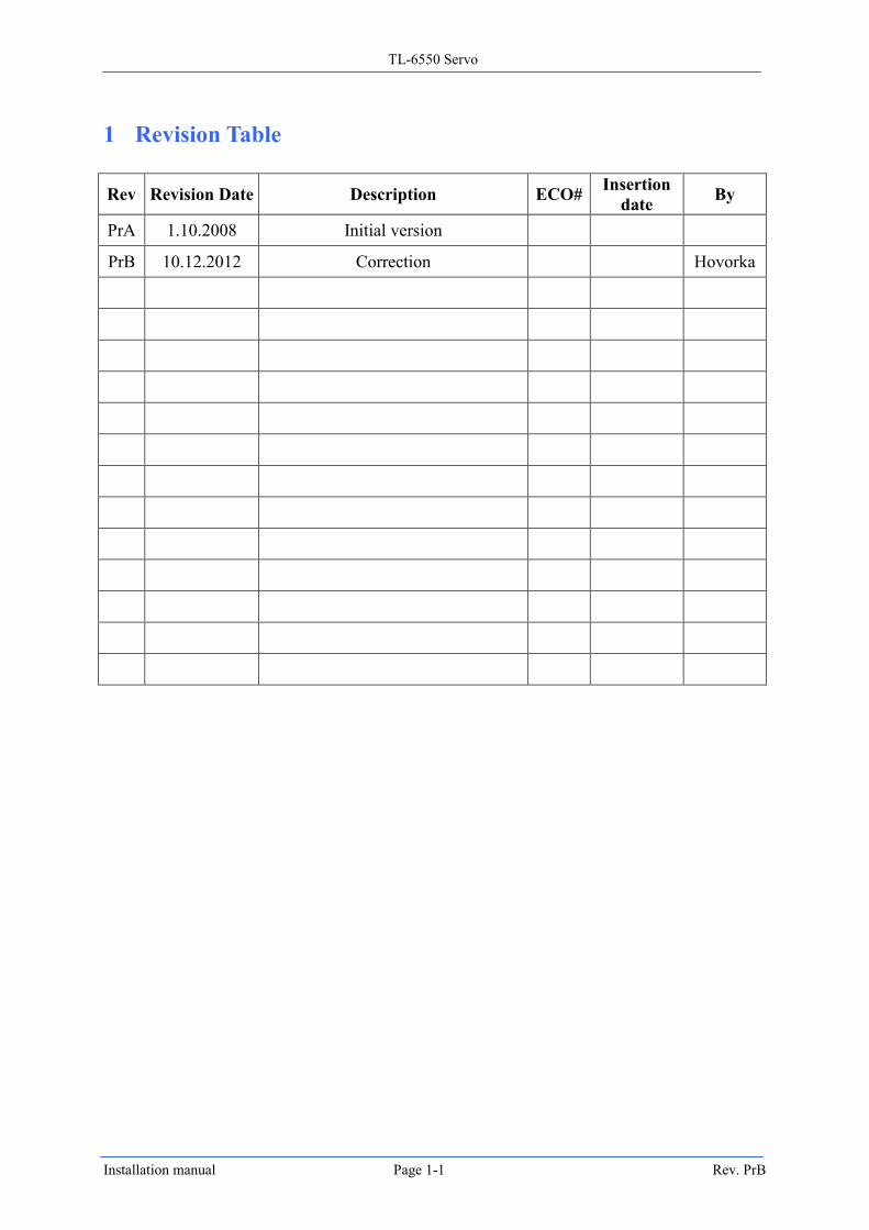
1 Revision Table
Rev Revision Date Description ECO# Insertion
date By
PrA 1.10.2008 Initial version
PrB 10.12.2012 Correction Hovorka
TL-6550 Servo
Installation manual Rev. PrB Page 2-1
2 General description
2.1 General Information
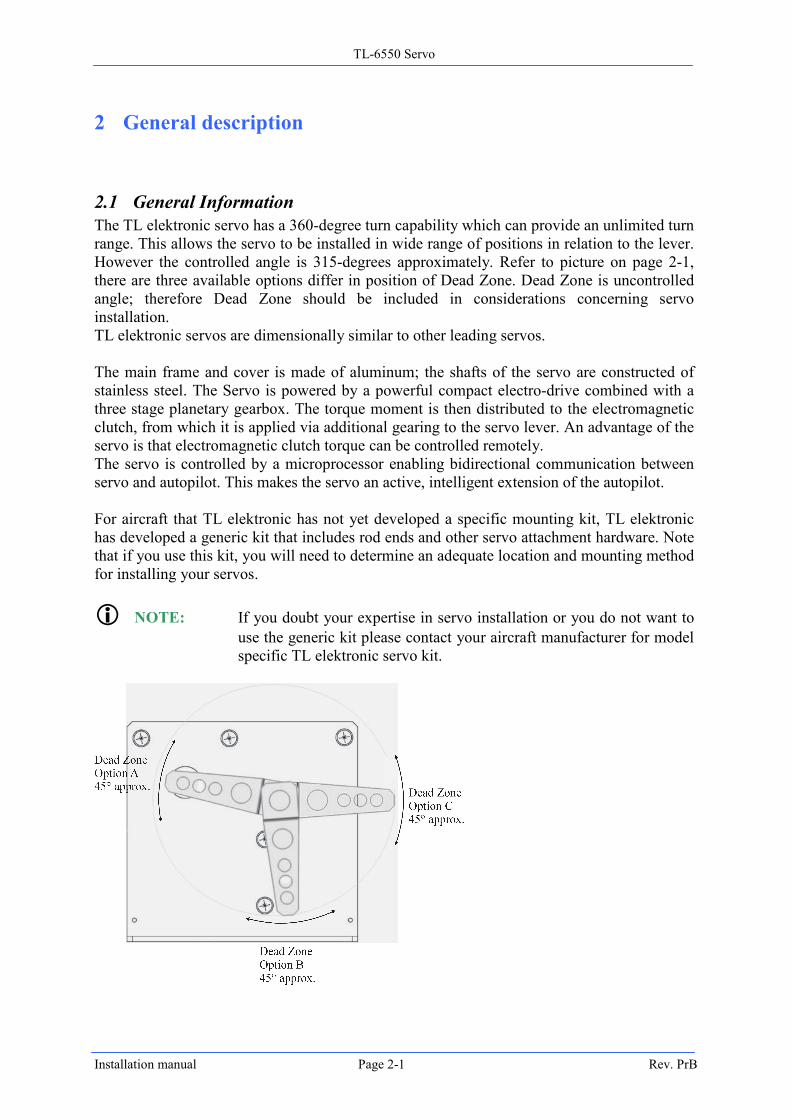
The TL elektronic servo has a 360-degree turn capability which can provide an unlimited turn
range. This allows the servo to be installed in wide range of positions in relation to the lever.
However the controlled angle is 315-degrees approximately. Refer to picture on page 2-1,
there are three available options differ in position of Dead Zone. Dead Zone is uncontrolled
angle; therefore Dead Zone should be included in considerations concerning servo
installation.
TL elektronic servos are dimensionally similar to other leading servos.
The main frame and cover is made of aluminum; the shafts of the servo are constructed of
stainless steel. The Servo is powered by a powerful compact electro-drive combined with a
three stage planetary gearbox. The torque moment is then distributed to the electromagnetic
clutch, from which it is applied via additional gearing to the servo lever. An advantage of the
servo is that electromagnetic clutch torque can be controlled remotely.
The servo is controlled by a microprocessor enabling bidirectional communication between
servo and autopilot. This makes the servo an active, intelligent extension of the autopilot.
For aircraft that TL elektronic has not yet developed a specific mounting kit, TL elektronic
has developed a generic kit that includes rod ends and other servo attachment hardware. Note
that if you use this kit, you will need to determine an adequate location and mounting method
for installing your servos.
NOTE: If you doubt your expertise in servo installation or you do not want to
use the generic kit please contact your aircraft manufacturer for model
specific TL elektronic servo kit.
TL-6550 Servo
Installation manual Rev. PrB Page 2-2
2.2 Limited Warranty
This manual contains important information that may affect the safety of the pilot,
passengers, aircraft and operation of the system or time to install the system. You MUST
read the manual prior to installing this system. Any deviation from these installation
instructions is the sole responsibility of the installer and should be done in accordance with
AC 43.13. Read the Warranty/Agreement. There is information in the Warranty/Agreement
that may alter your decision to install this product. If you do not accept the terms of the
Warranty/Agreement, do not install this product. This product may be returned for a refund.
Contact TL elektronic Inc. for details.
V WARNING: If the installer does not have the skills, knowledge, tools, equipment
or facility, to perform and determine whether the installation of this
product is safe, reliable and accurate and to determine whether this
product is operating properly after installation, DO NOT INSTALL
THIS PRODUCT. If the owner/pilot and/ or installer are unwilling to
take the responsibility for the installation and operation of this product,
DO NOT INSTALL THIS PRODUCT. This product may be returned
for a refund. Contact TL elektronic Inc. for details.
NOTE: By installing this product, the aircraft owner/pilot and installer agrees
to hold TL-elektronic Inc. in no way responsible for monetary
compensation, including punitive damages for any incident, harm
and/or damage associated with this product. If you do not agree to the
above, DO NOT INSTALL THIS PRODUCT. This product may be
returned for a refund. Contact TL elektronic Inc. for details.
NOTE: TL-elektronic Inc. is not liable or responsible for a pilot’s action or
any situation that results in personal injury, property damage, missed
commitments, lack of use of an aircraft or any expenses incurred due
to: product failure, inaccuracy in data provided, format issues,
software bugs or problems, upgrade or customization issues,
misinterpretation of data, calibration problems, installation issues
(leaks, incorrect wiring, obstructions, damage to aircraft or
components, incorrect installation of any parts, wrong parts, parts that
don’t fit, etc.) or any other issues related to the installation or
operation of this product. All of the above are solely the pilot’s and/or
installer’s responsibility. The pilot must understand the operation of
this product before flying the aircraft. The pilot will not allow anyone
to operate the aircraft that does not know the operation of this product.
V WARNING: Do not install a non-certified Servo in a certified aircraft.
TL-6550 Servo
Installation manual Rev. PrB Page 3-1
3 Technical Specifications
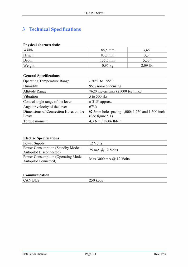
Physical characteristic
Width 88,5 mm 3,48”
Height 83,8 mm 3,3”
Depth 135,5 mm 5,33”
Weight 0,95 kg 2.09 lbs
General Specifications
Operating Temperature Range - 20°C to +55°C
Humidity 95% non-condensing
Altitude Range 7620 meters max (25000 feet max)
Vibration 5 to 500 Hz
Control angle range of the lever ± 315° approx.
Angular velocity of the lever 67°/s
Dimensions of Connection Holes on the
Lever Ø 5mm hole spacing 1,000; 1,250 and 1,500 inch
(See figure 5.1)
Torque moment 4,3 Nm / 38,06 lbf-in
Electric Specifications
Power Supply 12 Volts
Power Consumption (Standby Mode –
Autopilot Disconnected) 75 mA @ 12 Volts
Power Consumption (Operating Mode –
Autopilot Connected) Max.3000 mA @ 12 Volts
Communication
CAN BUS 250 kbps
TL-6550 Servo
Installation manual Rev. PrB Page 4-1
4 Install Recommendation
4.1 Introduction
Careful planning and consideration are required to achieve the desired performance and
reliability from the Servo. The performance and reliability of the servo is determined by
careful planning and consideration in its installation. Please follow the suggested guidelines.
4.2 Location Consideration
For proper servo operation, the servo must be mounted in a location which assures proper
interaction with the existing control system.
This location must permit the servo lever and associated linkage to move freely through the
entire range of motion. To prevent the possibility of the servo lever going over center, the
servo lever must not turn more than a total of +/-60º from neutral position throughout the
control system's range of motion.
4.3 Installation
The diagram below shows the outer dimensions of the Servo.
The TL elektronic servo mounting kit includes some of the basic hardware to mount and
connect servo to the aircraft control system. This kit can be used in pitch, roll or yaw
applications that use a servo with an output lever.
Once a mounting location has been determined, the next step is to fabricate a servo mount to
attach it to the aircraft. This attachment can be done with a bracket made of sheet metal or
corner stock. We recommend using aluminum with a proper thickness for the best balance of
strength to weight. When fabricating a mounting bracket take the servo dimensions into
consideration.
Leave enough room to permit the lever and attached linkage to move through a complete
range of motion. We recommend that all 4 of the include screws be installed with star
washers and flat washers to secure the servo to a mounting bracket. All screws supplied by
TL elektronic have drilled heads for use with safety wire. The final method for mounting the
servo/bracket in the aircraft is to be determined by the installer.
The distance between the servo lever and the control system attachment point must allow for
the angle between the servo lever and the push rod to be at approximately 90º when the
controls are at neutral.
When using the TL elektronic mounting kit, we suggest first installing the linkage on one of
three holes on the servo lever.
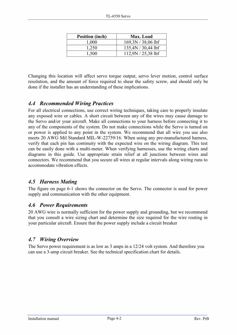
Pay attention to the table below illustrating the maxim load that can be applied to each
position on the lever.
TL-6550 Servo
Installation manual Rev. PrB Page 4-2
Position (inch) Max. Load
1,000 169,3N / 38,06 lbf
1,250 135,4N / 30,44 lbf
1,500 112,9N / 25,38 lbf
Changing this location will affect servo torque output, servo lever motion, control surface
resolution, and the amount of force required to shear the safety screw, and should only be
done if the installer has an understanding of these implications.
4.4 Recommended Wiring Practices
For all electrical connections, use correct wiring techniques, taking care to properly insulate
any exposed wire or cables. A short circuit between any of the wires may cause damage to
the Servo and/or your aircraft. Make all connections to your harness before connecting it to
any of the components of the system. Do not make connections while the Servo is turned on
or power is applied to any point in the system. We recommend that all wire you use also
meets 20 AWG Mil Standard MIL-W-22759/16. When using any pre-manufactured harness,
verify that each pin has continuity with the expected wire on the wiring diagram. This test
can be easily done with a multi-meter. When verifying harnesses, use the wiring charts and
diagrams in this guide. Use appropriate strain relief at all junctions between wires and
connectors. We recommend that you secure all wires at regular intervals along wiring runs to
accommodate vibration effects.
4.5 Harness Mating
The figure on page 6-1 shows the connector on the Servo. The connector is used for power
supply and communication with the other equipment.
4.6 Power Requirements
20 AWG wire is normally sufficient for the power supply and grounding, but we recommend
that you consult a wire sizing chart and determine the size required for the wire routing in
your particular aircraft. Ensure that the power supply include a circuit breaker
4.7 Wiring Overview
The Servo power requirement is as low as 3 amps in a 12/24 volt system. And therefore you
can use a 3-amp circuit breaker. See the technical specification chart for details.
TL-6550 Servo
Installation manual Rev. PrB Page 4-3
4.8 Safety Features
4.8.1 Emergency Disconnect
The Emergency Disconnect Switch is a failsafe system. Flipping the switch disconnects
power to the Auto Pilot servo and disables the Electro-Magnetic clutch. This instantly
restores full control of the aircraft to the pilot in the event of instrument or system
malfunction.
The Emergency Disconnect Switch is an essential part of the TL elektronic autopilot system.
Its installation is mandatory.
4.8.2 Data Delay Disconnect
In the event the Auto Pilot Servo does not receive data or the digital information stream is cut
off from the Integra/Autopilot, the autopilot servo will automatically disconnect restoring full
control of the aircraft to the pilot.
TL-6550 Servo
Installation manual Rev. PrB Page 5-1
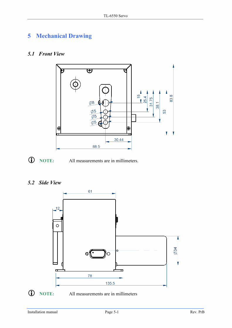
5 Mechanical Drawing
5.1 Front View
NOTE: All measurements are in millimeters.
5.2 Side View
NOTE: All measurements are in millimeters
TL-6550 Servo
Installation manual Rev. PrB Page 5-2
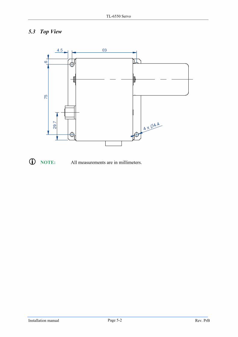
5.3 Top View
NOTE: All measurements are in millimeters.
TL-6550 Servo
Installation manual Rev. PrB Page 6-1
6 Electrical Drawing
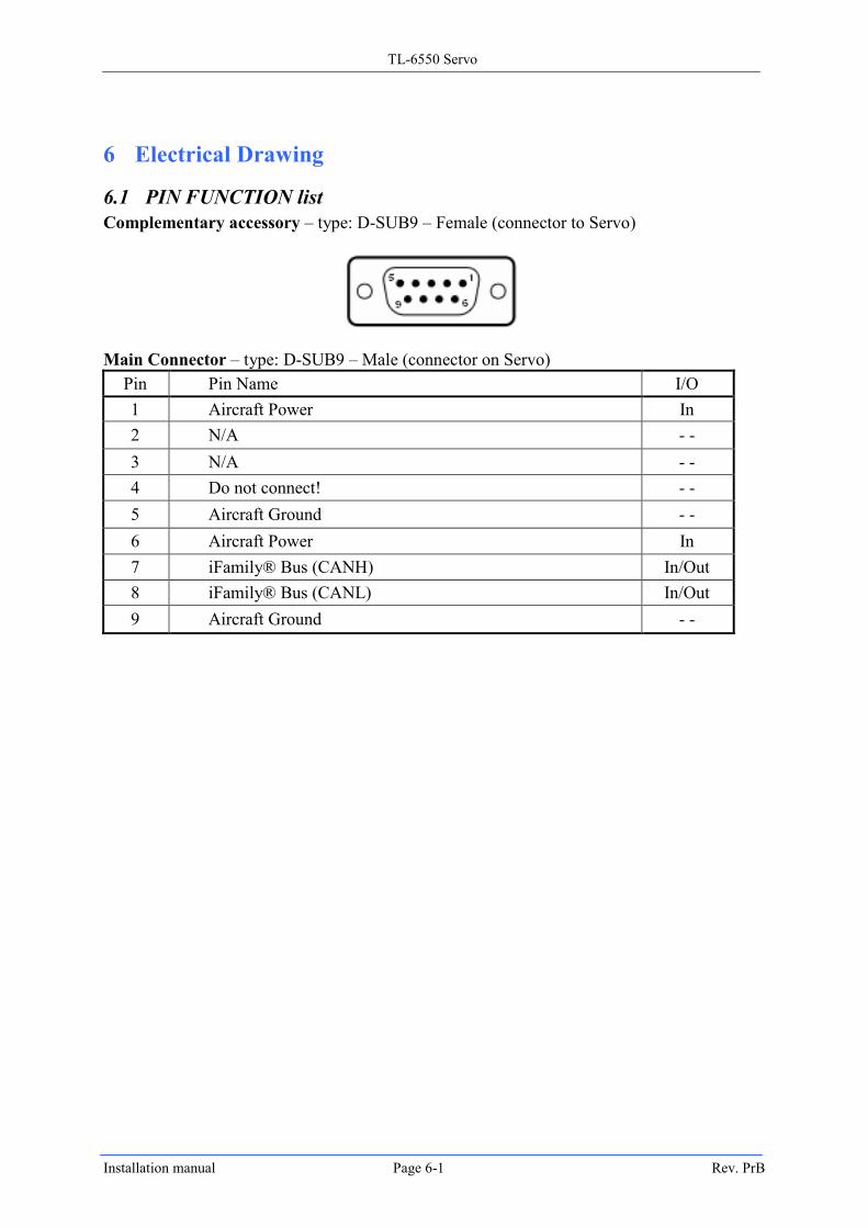
6.1 PIN FUNCTION list
Complementary accessory – type: D-SUB9 – Female (connector to Servo)
Main Connector – type: D-SUB9 – Male (connector on Servo)
Pin Pin Name I/O
1 Aircraft Power In
2 N/A - -
3 N/A - -
4 Do not connect! - -
5 Aircraft Ground - -
6 Aircraft Power In
7 iFamily® Bus (CANH) In/Out
8 iFamily® Bus (CANL) In/Out
9 Aircraft Ground - -
TL-6550 Servo
Installation manual Rev. PrB Page 6-2
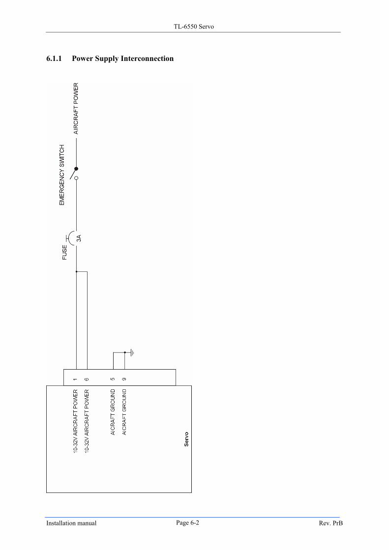
6.1.1 Power Supply Interconnection
TL-6550 Servo
Installation manual Rev. PrB Page 6-3
iFAMILY® BUS2
iFAMILY® BUS2
INTEGRA
P02
SERVO
1
14
7
8
iFAMILY® BUS (CANH)
iFAMILY® BUS (CANL)
120Ω/0,6W
120Ω/0,6W
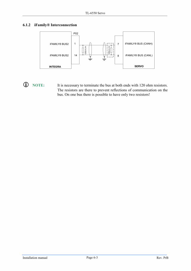
6.1.2 iFamily® Interconnection
NOTE: It is necessary to terminate the bus at both ends with 120 ohm resistors.
The resistors are there to prevent reflections of communication on the
bus. On one bus there is possible to have only two resistors!
TL-6550 Servo
Installation manual Rev. PrB Page 7-1
7 Conclusion
INSTRUCTIONS FOR RETURN
If none of the above sections have helped resolve an ongoing issue with your Servo, please
call TL elektronic at +420 495 48 23 93 to discuss the issue with Technical Support.
In case the issue cannot be resolved, we will provide you with an RMA number to use when
shipping the Servo to us. If your unit is still under warranty, the repairs will be performed
and the Servo will be returned promptly. If your warranty has expired, the TL elektronic
representative will make arrangements with you and make you fully aware of the costs before
proceeding with the repair.
While TL elektronic makes every effort to save and restore your unit’s settings and
calibrations, we cannot guarantee that this will happen. Please note that after you receive
your unit back from TL elektronic with a factory calibration, the servo may be inaccurate
once re-installed in your aircraft.