sesame storage ring rf-system sesame-tac meeting nov.2012 sesame sr rf system – darweesh foudeh
TRANSCRIPT

SESAME STORAGE RINGRF-SYSTEM
SESAME-TAC meeting Nov.2012
SESAME SR RF System – Darweesh FOUDEH

SESAME SR MAIN PARAMETERSParameter Value
Energy 2.5 GeV
Circumference 133.20 m
RF frequency 499.654 MHz
Radiation loss/turn 605 KeV
Beam current (maximum) 400 mA
Beam power loss (bare machine)
242 kW
Harmonic number 222
Momentum compaction factor 0.00828
Total RF voltage (maximum) 2.4 MV
Over voltage factor 4
Number of cavities 4
Energy acceptance 1.45 %
Synchrotron frequency 37 KHz
Synchronous phase 165.5 º
SESAME-TAC meeting Nov.2012
SESAME SR RF System – Darweesh FOUDEH

Parameter Booster Storage ring
RF frequency 499.654 MHz 499.654 MHz
Harmonic number 64 222
Circumference 38.4 m 133.20 m
Revolution freq. 7.807 MHz 2.25 MHz
RF wavelength 0.600 m 0.600 m
Coincidence freq. 70.334 KHz
SESAME RF Layout and Main Parameters
SESAME-TAC meeting Nov.2012
SESAME SR RF System – Darweesh FOUDEH

SESAME SR RF SYSTEM GENERAL LAYOUT
So far, the above analog LLRF has been suggested for the Storage Ring
As a strong alternative, adopting a digital LLRF for the Storage Ring RF system is being studied. A proposal for establishing a collaboration between ALAB & SESAME to build the SESAME DLLRF
SESAME-TAC meeting Nov.2012
SESAME SR RF System – Darweesh FOUDEH

Main Oscillator500 MHz
Local Oscillator20 MHz
ADC
ADCFPGAFPGA
DSP/PIDDSP/PID
DAC
DACAmp
520 MHz
500 MHz (Cavity Signal)
IF
IF
20 MHz
20 MHz
Digital Clock (80 MHz)
I´
Q´
Cavity
Cavity Tuning Stepper Motor
500 MHz (Forward Signal)
500
MHz
520 MHz
520 MHz
Digital IQ Demodulation
Proposed Digital LLRF System
SESAME-TAC meeting Nov.2012
SESAME SR RF System – Darweesh FOUDEH

Advantages
Flexible and Reconfigurable via Software.
Many sophisticated algorithms can be implemented via software.
Remotely controlled and multi-user operation.
DLLRF has built-in diagnostics, low down-time (MTBF), and high resolution is achievable.
Disadvantages
Long group delay.
More sensitive to radiation.
Needs good programming skills to develop software programs.
Digital LLRFSESAME-TAC meeting Nov.2012
SESAME SR RF System – Darweesh FOUDEH

SESAME SR RF Power Amplifier SESAME has adapted the SSA technology instead of vacuum tubes due to:
•
absence of high biasing voltages.
• longer life times.• stable gain with aging.• easier and quicker maintenance and no machine interruption.• possibility of reduced power operation in case of failure.
SOLEIL design for 500MHz module had been adapted as the main block for building the amplifier tower based on the LDMOS BLF578XR transistors from NXP Semiconductors. The –XR version showed lower performance compared to prior one, so it was
dumped and will not be used to drive the RF module.BLF578XR
BW MHz PL
VSWR @225MHz P.Oper & PL 1200W; 1400
GainD
%
10-500 1200 13:1 24dB 7010-500 1400 65:1 23.5 69
SESAME-TAC meeting Nov.2012
SESAME SR RF System – Darweesh FOUDEH

SESAME SSA main block showing:•Power transistor with the surrounding circuit.•2KW circulator on the output with (495-505) MHz BW.•350W dummy load.
SESAME-TAC meeting Nov.2012
SESAME SR RF System – Darweesh FOUDEH

SESAME SSA main module tests.•Two colleagues from the RF group had visited SOLEIL to do all required tests.•Phase1 tests were based on testing each module by itself, two groups of the module were identified, one is using the BLF578 x 8 and the other is using BLF578XR x 6.•Phase2 tests were made for the whole group test as one amplifier.•Phase3 tests were made by combining the two groups.The desired output level for each module was 650W@500MHz for both groups.
BLF578 Module
Dissipated Power W
S11
dBGaindB
%
%
Phase Shift
380 -50 16.3 63 3.2 25
BLF578XR Module
Dissipated Power W
S11
dBGaindB
%
%
Phase Shift
517 -54 15.4 55 1.8 -31
SESAME-TAC meeting Nov.2012
SESAME SR RF System – Darweesh FOUDEH

Gain vs. Pout for each module•BLF578: 16.3 dB.•BLF578XR: 15.4 dB.
SESAME-TAC meeting Nov.2012
SESAME SR RF System – Darweesh FOUDEH

Efficiency vs. Pout•BLF578: 63%.•BLF578XR: 55%.
SESAME-TAC meeting Nov.2012
SESAME SR RF System – Darweesh FOUDEH
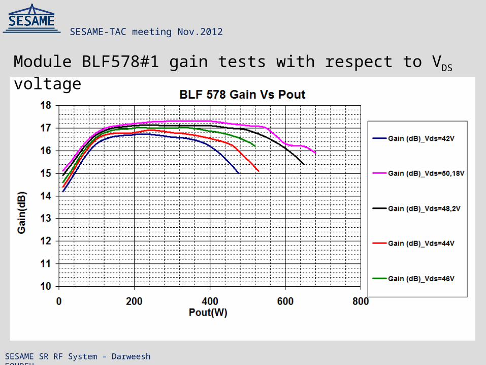
Module BLF578#1 gain tests with respect to VDS voltage
SESAME-TAC meeting Nov.2012
SESAME SR RF System – Darweesh FOUDEH

Module BLF578#1 efficiency tests with respect to VDS voltage
SESAME-TAC meeting Nov.2012
SESAME SR RF System – Darweesh FOUDEH

Gain & Efficiency vs. combined power of the BLF578 modules Efficiency vs. pout Prototype _8 modules_BLF578
0
10
20
30
40
50
60
70
0 1 2 3 4 5 6
Pout(kW)
Eff
icie
nc
y (
%)
SESAME-TAC meeting Nov.2012
SESAME SR RF System – Darweesh FOUDEH

G & η vs. output power: combined output power of 6LF578 + 6BLF578XR
SESAME-TAC meeting Nov.2012
SESAME SR RF System – Darweesh FOUDEH

SESAME-TAC meeting Nov.2012
SESAME SR RF System – Darweesh FOUDEH
Module Degradation Test
•Two groups of 8-Modules each were prepared.•First group was tested with 650W to give a total output of 5.2KW for 1000h.•Second group was tested with 725W to give a total output of 5.8KW for 1000h.•The results of tests showed stable performance after 1000h.•After the 1000h test is finished each module will be tested individually to check all its parameters in details.

DC-DC converter300V–to- 50V
RF tower power supply implemented in SOLEIL
RF tower power supply will be implemented in SESAME; 220ACV-to-50VDC/2KW.
SESAME-TAC meeting Nov.2012
SESAME SR RF System – Darweesh FOUDEH

4.8KW
24W0.6W
600W120W3W
38.4KW
000
4.8KW
600W120W 3W
24W
0.6W38.4KW
2-WayCombiner
76.8KW
SESAME 75KW tower Solid State Amplifier architecture
All RF modules have 16dB gain@600W output.
SESAME-TAC meeting Nov.2012
SESAME SR RF System – Darweesh FOUDEH

SESAME RF PLANT LAYOUTSESAME-TAC meeting Nov.2012
SESAME SR RF System – Darweesh FOUDEH

SOLEIL Storage Ring RF Solid State Amplifiers (SSA)
SESAME-TAC meeting Nov.2012
SESAME SR RF System – Darweesh FOUDEH

SESAME-SOLEIL Collaboration• Two RF cavities had been received by SOLEIL from Elettra by the end of May2012.
• One of them has the HOM shifter while the other doesn’t.
• By visual inspection the cavities look in good shape but its cooling pipes need re-welding.
• Max. RF power through its input coupler is 60KW.
• Testing RF plant will be built consist of:
1. RF Cavity.
2. 75KW amplifier.
3. Waveguides.
4. Cooling rack for cavity.
5. Shielding room for cavity operation.
SESAME-TAC meeting Nov.2012
SESAME SR RF System – Darweesh FOUDEH

• Due to input coupler power limitations the two Elettra cavity will be used mainly for the phase1 commissioning of the SR.
• Max. stored current will be around 25mA.
• To operate the SR at 2.5GeV/400mA with extra 100KeV due to ID’s and 4 OVF would require each cavity to be able to handle 150KW.
• Other options are under investigation, i.e.:
EU cavity.
PEP2 cavity.
KEK damped cavity.
Elettra cavity with the new I/P coupler design.
SESAME-TAC meeting Nov.2012
SESAME SR RF System – Darweesh FOUDEH
SR Power Requirements

SESAME SR RF Cavities
Tw ± 0.1°C
Power coupler
LLcaca
vv
PlungerPhase1: 2Elettra cavities
with 60KW.max I/P CouplerPhase2: Chosen cavities should be capable to compensate the energy losses of about 700KeV@400mA
SESAME-TAC meeting Nov.2012
SESAME SR RF System – Darweesh FOUDEH

SESAME-TAC meeting Nov.2012
SESAME SR RF System – Darweesh FOUDEH
KEK damped cavity used in the PF-ring.

Local Control Unit (LCU)
Donated by Soleil
From BESSY I
Purchased by EU fund donation
Ready System: SESAME Booster RF Plant and Local Control
SESAME-TAC meeting Nov.2012
SESAME SR RF System – Darweesh FOUDEH

The new 2kW Solid-State amplifier as replacement for the old klystron used in BESSY I
Booster LLRF (from BESSY I) tested in the RF lab
Booster 2KW RF Cavity (BESSY1)
SESAME Booster RF Plant
SESAME-TAC meeting Nov.2012
SESAME SR RF System – Darweesh FOUDEH

Thank You
SESAME-TAC meeting Nov.2012
SESAME SR RF System – Darweesh FOUDEH