set-up use maintenance troubleshooting schematicssailrite fabricator set-up inspecting the machine....
TRANSCRIPT

Set-Up • Use • Maintenance Troubleshooting • Schematics

Welcome to Your Fabricator Sewing Machine!
The Fabricator is a production machine that can sew all day with its best-in-class power system.
Add in its slow speed power and control, which allows you to truly sew stitch-by-stitch, and you’ve got yourself a new trusty sidekick for all your canvas and upholstery projects.
This guidebook will give you in-depth knowledge of your machine including getting set-up, sewing, advanced maintenance and troubleshooting.

Table Of ContentsSewing Machine Safety ...............................................1
Sailrite Fabricator Set-Up ..........................................2 Power Stand Assembly ..............................................3 Installing the Drawer ...................................................5 Installing Rubber Foot Pads .......................................6 Installing the Treadle ..................................................7 Installing the Linkage Bar ...........................................8 Oil Pan and Machine Installation ................................9 Check Motor Rotation ............................................... 11 Securing the Stitch PRO Balance Wheel .................12 Belt Adjustment for the Workhorse Servo Motor ......13 Attaching the Balance Wheel Belt Cover .................14 Attaching the Bobbin Winder ....................................15 Mounting the Led Light .............................................16 Mounting the Thread Stand ......................................16 Installing the Knee Lift Assembly ..............................17 Check the Machine for Operation .............................18 Auto Lubrication .......................................................19 Manual Oiling ...........................................................21
Coordinating the Needle, Thread and Material Installing Needles .....................................................25 Thread Recommendations .......................................26
Preparing to Sew How to Wind a Bobbin ..............................................28 Bobbin Thread Winding Adjustment .........................30 Removing and Installing the Bobbin Case ...............31 How to Thread the Bobbin ........................................32 Threading the Sewing Machine ................................33 Pulling Up the Bobbin Thread...................................35
Sewing with the Sailrite Fabricator Starting to Sew .........................................................36 Setting the Stitch Length & Operating in Reverse ...............................................37 Adjusting the Pressure of the Presser Feet ..............38 Adjusting Upper Tension Assemblies .......................39 Adjusting Bobbin Thread Tension .............................40 Removing Material from Under the Presser Feet .....41 Sewing in Light to Moderate Weight Fabrics ............41
Fabricator Maintenance Feed Dog Height Adjustment ...................................43 Setting the Feed Dog Position ..................................44 Adjusting Needle Position & Clearance Between Presser Feet ..............................................45 Timing Between the Needle & the Rotating Hook ....46 Adjusting the Presser Foot Lift .................................50 Adjusting the Vertical Lift of the Outer Presser Foot .........................................51 Adjusting Feed Timing of the Needle Bar, Presser Foot and Feed Dog .....................................52 Stitch Length Adjustment Between Forward & Reverse ..................................................53 Adjusting the Thread Take-Up Spring .......................54
Troubleshooting Skipped Stitches .......................................................56 Lack of Stitch Tension...............................................57
Schematics.................................................................58Machine Specifications .............................................75Warranty .....................................................................76

1 | Sailrite.com
SEWING MACHINE SAFETY
• Do not operate in conditions where you or the machine are or may become wet.
• Operate the machine on a firm, level surface where there is adequate room for safe operation.
• Observe caution when placing your hands or other parts of your body or clothing near any moving parts including but not limited to the following: the walking foot, the needle, the drive belt, the balance wheel and any of its parts.
• Do not run the machine without its covers.
• Do not stop the movement of the balance wheel with your hands.
• Use caution in tilting the machine backwards in its table and in lowering it back into the table.
• Use proper lifting techniques when moving the machine.
• Do not drop the machine.
• Always use the proper voltage required for the motor and light.
• Wear protective eyewear when sewing.
• Wear shoes when operating the foot pedal.
• Provide supervision when allowing others to use the machine—particularly children and those who are unfamiliar with the machine’s operation.
• Do not use around flammable materials.
• Use both hands to feed and guide the material while the belt and balance wheel are in motion.
• Maintain a safe distance from the belt and balance wheel when the machine is in motion.
• The operator’s hand should not be near the wheel pinch point (where moving parts may cause harm to the user) except to raise and lower the needle, and only when the motor is disengaged.
Please observe the following when using your Sailrite sewing machine
WARNING: Some products may be fabricated from materials which may contain chemicals known to the state of California to cause cancer, birth defects or other reproductive harm.

Sailrite Fabricator Guidebook | 2
Our expert Sailrite technicians have checked and adjusted every component of this machine. It has been sewn off and all accessories have been prepared for easy installation. With this guidebook, you should be able to maintain and adjust your own machine. Please do not make substantial adjustments to machine settings unless in consultation with Sailrite.
Unpacking the Sailrite FabricatorTo remove the casting from the box, it is best to have help. While one person holds the box down on the floor, the other should reach under the arm of the machine and lift straight up. Set the machine on a solid surface or floor.
Tip: Place a newspaper or old towel down first to absorb any oil and protect the surface.
SAILRITE FABRICATOR SET-UP
Inspecting the MachineBefore use, thoroughly inspect the machine. It will arrive threaded with a fabric sample under the presser feet. To remove the fabric, untie the thread from the top of the machine and lift the presser feet with the hand lever (A). Make sure the needle is up, out of the fabric and pull the sample and all thread free from the top of the machine. Cut the bobbin thread and let it lay loose. See page 41 for complete steps.
1
A

3 | Sailrite.com
Power Stand Assembly1. Find parts A, B, C and D. Stand both k-legs
upright and bolt the back support bar (E) to the bottom hole at the back of the table legs (Figure 2).
2. Find parts F, G and H. Flip the legs upside-down and place the treadle mount bar (I) at the back of the forward most slots (Figure 3). Bolt the treadle mount bar to the bottom surface of each crossbar of the k-legs (Figure 4).
2
3
GF H
A
B
C
FRONT
D
4
E
I

Sailrite Fabricator Guidebook | 4
5
6
7
1.5"
0.5"
J
M
K L
3. Place the top of the table on the floor with the laminate surface down. Place on a soft surface to avoid scratching the tabletop. Squarely line up the table legs as shown (Figure 5). Be sure that the legs are facing the correct direction. Reference the cutout shape in the tabletop to aid in placement.
4. Use a pencil to mark screw locations for attaching the K-leg frame to the tabletop (Figure 6). Use a 5/32" drill bit and drill about 1/2" into the tabletop. Do not drill completely through.
5. Bolt the frame to the bottom of the tabletop using the enclosed hex head lag screws (J), locking washer (L) and washer (M) to lock at each position (Figure 7).

5 | Sailrite.com
Installing the DrawerThe drawer mounts to the forward, left, underside of the table when the stand is upright. To install the drawer, locate the rough position (Figure 8) and put the drawer rails and the drawer in position. The drawer should pull open from the front of the table (Figure 9) and when pushed in, it will hit a stop. Secure the rails to the underside of the table with the included screws (K) on page 4 (Figure 10).
Tip: Do not over tighten the screws or they will prevent the drawer from sliding freely.
10
9FRONT
Drawer Location
8FRONT

Sailrite Fabricator Guidebook | 6
Installing Rubber Foot PadsStretch the K-Leg foot pads onto the rectangular metal feet of the table legs (Figure 11).
Flip the table upright.
If the height needs adjusted, move the bolts up or down in the leg slots and holes then lock in place (Figure 12). Be sure to adjust the height before placing the sewing machine casting in the tabletop.
Be sure all nuts and bolts are tight.
11
12

7 | Sailrite.com
Installing the TreadleThe treadle is typically installed near the center of the treadle mount bar, but it can be set to the user’s preference anywhere on the bar.
After determining placement and taking note of desired location of the treadle, flip the table onto its back side (Figure 13).
The two end pivots (A) fit into the sides of the treadle pedal and are then bolted to the mount bar with 4 bolts to hold it in position (Figure 13-14).
The rubber pad will be face up and the side with the bolt holes will be to the back of the table (away from the machine operator). These holes will be used to attach the treadle to the motor.
Tip: Install the pivots first but do not tighten completely. Then place the treadle in position between the pivots and tighten bolts. Flip the table upright and check to make sure the treadle moves freely after the bolts are tightened.
BEFORE CONTINUING: See “Attaching a Pulley” and “Installing the Workhorse Servo Motor” in the Workhorse Servo Motor Instructions.
A
13
14

Sailrite Fabricator Guidebook | 8
Installing the Linkage BarBolt the L-bracket (B) to the holes on the back of the treadle so that its shorter leg is sticking out toward the back of the table pointing toward the Workhorse motor. (Figure 15). The short leg should be roughly vertical to the motor operation lever (C).
Bolt the linkage bar (D) to the outer most hole of the motor operation lever on the Workhorse and the L-bracket (Figure 16).
By increasing or decreasing the overlap of the linkage bar, different treadle pedal angles can be achieved. Use a size 14mm wrench to set the angle to your preference (Figure 17).
B
C
D
15
16
17

9 | Sailrite.com
Oil Pan and Machine InstallationLocate the two back corner cushions (A), the two front corner cushions (B) and the two hinge cushions with chrome hinges (C).
Take out the cast aluminum oil tray (D) and slide the four corner cushions onto each respective corner flange (Figure 18-19).
With the table upright, tilt the tray into the tabletop cutout so that all four corner cushions drop down into the ledges. The edge of the oil tray with the crescent cutout should be facing the left side of the table, away from the belt slot. (Figure 19).
D
A
AA
B
BB
C
18
19

Sailrite Fabricator Guidebook | 10
Push the machine Support Pin (E) into the hole in the tabletop nearest the carriage bolts holding the motor. The fit may be tight so just push until snug (Figure 20).
Insert the tapered end of the knee lift post connector (F) into the raised hole in the bottom of the oil tray (G) (Figure 21).
Find the magnet for the oil tray (H) and place it in the bottom of the oil tray (Figure 21).
Next, take the rubber pads off of the chrome hinges (C) and place them into their respective tabletop cavities (I). Insert the two chrome hinges into the two holes located on the back side of the sewing machine (J).
With help, lift and lower the sewing machine into the tabletop so that the chrome hinges fit into the rubber pads (Figure 22).
E
F
G
H
20
21
22
I
J

11 | Sailrite.com
Check Motor RotationThe machine’s motor shaft should rotate counterclockwise when viewed from the motor shaft end. Plug in the motor, switch the power on and press down on the foot treadle to confirm operation now.
If motor rotation is not counterclockwise, please refer to “Changing Motor Rotation” in the Workhorse Installation Instructions.
23

Sailrite Fabricator Guidebook | 12
Securing the Stitch PRO Balance Wheel Remove the Posi-Pin (wrapped in plastic) from the Posi-Pin Wheel Bushing on the upper shaft of the sewing machine.
Remove the three screws (A) for the belt cover installation (Figure 24). Position the C-shaped belt guard and reinstall the screws making sure washers are positioned as shims behind the guard to keep it from being bent out of shape (Figure 25).
Unscrew the reverse-threaded Posi-Pin Nut (B). Slide the Stitch PRO Balance Wheel onto the Posi-Pin Wheel Bushing (C), making sure it does not interfere with the belt cover. If the wheel hits the belt cover, reposition the washers placed under the C-shaped belt guard or move the bushing out further by loosening the set screws in the bushing.
Thread the reverse-threaded nut back onto the bushing and tighten by hand. Rotate the balance wheel until the hole in the balance wheel is aligned with one of the four bushing holes. Push the Posi-Pin (D) through the holes to lock the balance wheel to the bushing (it will spring back slightly). Rotation of the balance wheel will now cause the machine to function (Figure 26).
24
A
25
B
C
D
26

13 | Sailrite.com
Belt Adjustment for the Workhorse Servo Motor Before installing the drive belt, loosen the hex head set screw (A) with a 5/32" Allen wrench to allow the Workhorse Servo Motor to freely pivot (Figure 27). This will prevent the belt from stretching or breaking while being installed.
With the machine tilted back, slip the drive belt over the balance wheel track and guide it onto the motor pulley then carefully lower the machine into the cutout while judging belt tension (Figure 28). If the tension needs to be adjusted, follow the directions below:
Pivot the motor back to tighten the belt and forward to loosen it. Proper adjustment of the belt results in 3/8" of slack when pressed by finger at its center. Retighten set screw (A). The Linkage Bar may also need to be readjusted (page 8).
Once installed, the belt should not touch the table and should be centered on the track of both the balance wheel and motor pulley. Adjust the positioning of the motor left and right by loosening and sliding the bolts within the slots of the motor bracket.
Once the motor is in the correct position and all bolts are tightened, remove the belt so the pulley bracket can be installed.
BEFORE CONTINUING: See “Installing the Pulley Cover” in the Workhorse instructions.
28
A
27
Sailrite Fabricator Guidebook | 14
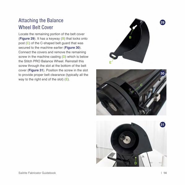
Attaching the Balance Wheel Belt CoverLocate the remaining portion of the belt cover (Figure 29). It has a keyway (B) that locks onto post (C) of the C-shaped belt guard that was secured to the machine earlier (Figure 30). Connect the covers and remove the remaining screw in the machine casting (D) which is below the Stitch PRO Balance Wheel. Reinstall this screw through the slot at the bottom of the belt cover (Figure 31). Position the screw in the slot to provide proper belt clearance (typically all the way to the right end of the slot) (E).
B
E
C
D
29
30
31

15 | Sailrite.com
Attaching the Bobbin WinderNow screw the bobbin winder to the tabletop. The large wheel of the winder should be about 1/8" forward of the belt (no contact) (Figure 32) and in line with the belt. The long edge of the bobbin winder should be parallel to the belt slot in the table (Figure 33). Mark the location in each of the slots where the screws will be positioned.
Remove the bobbin winder and using a 5/32" drill bit, create pilot holes about 3/8" deep. Place the bobbin winder so the slots are positioned over the pilot holes. Mount the bobbin winder to the tabletop with the two screws (A) positioned in the bobbin winder slots.
Note: The bobbin winder should be disengaged before installation.
Pressing the thumb pad (B) will move the wheel into the belt in order to wind bobbins. The thumb pad is on a hinged bracket so that when thread has filled the bobbin, the mechanism will disengage the wheel from the belt.
B
A
34
33
32

Sailrite Fabricator Guidebook | 16
Mounting the Flex20 LED Light:To attach the Flex20 LED light, place the light in your desired location on the machine and plug it into a wall socket (Figure 35).
Optional: Attach the included plastic clips to the back of the sewing machine and use the zip ties to hold the cord.
To attach the light to the front face of the machine (C), use the adhesive pad included with the Flex20 light.
Mounting the Thread Stand:Assemble the thread stand as shown (Figure 36). Secure it to the tabletop with included hardware.
35
36
C

17 | Sailrite.com
To install the knee lift lever (A) to the oil tray, slide the fitting onto the shaft which sticks out of the front of the oil tray (B). Position the bar so that the bend is facing toward the needle of the sewing machine and so the knee pad is easily engaged when sitting in front of the machine (Figure 37).
To lift the presser foot of the sewing machine, push the knee pad to the right and the foot will rise. Remove pressure and the foot will fall again.
The two set screws (C) found on the bottom of the oil pan determine how high the foot will lift and how much play there is in the knee lift lever when the presser foot is down. (Figure 38). These settings can be adjusted to suit the user’s preference. The screw on the right, closest to the belt, will influence how high the foot will raise. Loosen the nut and lower the set screw. Push the knee lift lever until the foot is near the max height possible. Tighten the set screw until it touches the oil tray. Tighten the nut to hold its location.
To remove undesired slack in the knee lift lever, adjust the left set screw, closest to the needle. Loosen the nut and push the knee lift lever until just before it engages the foot. Leave about one inch of play then tighten the set screw until it touches the oil tray. Tighten the nut to hold its location.
Installing the Knee Lift Assembly 37
38
C
B
A

Sailrite Fabricator Guidebook | 18
Check the Machine for Operation:Plug the motor in and flip the power switch on the motor front. Verify that there is no thread going through the needle’s eye and that the fabric sample is removed from under the foot. Make sure the presser foot is up and push down slowly on the top of the foot pedal to operate the machine. Use your heel to push the bottom of the pedal and the machine will stop. Turn the motor off.
See “Operation” in the Workhorse guidebook for more information and how to set the motor speed.

19 | Sailrite.com
Fill the oil tray with the oil found in the sewing machine box. Try to keep the oil level between the highest and lowest markings on the oil pan (Figure 39).
When it becomes necessary to change the oil, unscrew plug (A), wipe the dirty oil and the dust from the oil drip pan, replace the plug and add fresh oil. Use any high quality, clear sewing machine oil.
Auto Lubrication
39
ALowestHighest
Sailrite Fabricator Guidebook | 20
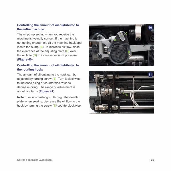
Controlling the amount of oil distributed to the entire machine:The oil pump setting when you receive the machine is typically correct. If the machine is not getting enough oil, tilt the machine back and locate the sump (B). To increase oil flow, close the clearance of the adjusting plate (C) over the oil hole (D) to increase vacuum pressure (Figure 40).
Controlling the amount of oil distributed to the rotating hook: The amount of oil getting to the hook can be adjusted by turning screw (E). Turn it clockwise to increase oiling or counterclockwise to decrease oiling. The range of adjustment is about five turns (Figure 41).
Note: If oil is splashing up through the needle plate when sewing, decrease the oil flow to the hook by turning the screw (E) counterclockwise.
40
41
E
B
C
D

21 | Sailrite.com
B
Remove the rubber plugs on top of the machine head (A & B) and put a small amount of oil in hole (A); then, lift the presser foot and run the machine at a moderate speed for a few seconds. (B) is an access hole to get to an internal oil port hole about 1" inside the machine. Occasional manual oiling of the hook and internal moving parts is recommended even for auto-lubricating sewing machines. Put a drop of oil on anything that looks like a gear, cam or slide (Figure 42-43).
Note: Once oiled, sew a scrap piece of material to make sure all excess oil is worked out of the machine so it does not leak onto your next project.
Manual Oiling
42
43
A

Sailrite Fabricator Guidebook | 22
43

23 | Sailrite.com
44

Sailrite Fabricator Guidebook | 24
Using the FabricatorNow that your machine is all set
up, it’s time to start sewing!
This next section will explain setting up the machine to sew including how to wind bobbins, thread the machine
and adjust the tension.

25 | Sailrite.com
Turn the balance wheel to lift the needle bar to its highest point. Loosen the needle set screw (A) and remove the old needle.
Needles have two distinct sides (Figures 45-46). One side has a long channel or groove (B) (locate this groove with your fingernail if you cannot see it) and the other side has a scarf (D) i.e., a carved out area just above the needle eye (C).
When inserting a new needle, make sure that
the needle groove (B) is facing left when the operator is seated in front of machine (Figure 46) and that the needle shank is all the way up before tightening the set screw (Figure 47).
Tip: To make sure your needle is inserted far enough, you can look through the sighting hole (E) near the bottom of the needle bar. Lower the needle bar to its lowest position to have a better view. The top of the needle should be fully visible in the sighting hole and pushed all the way to the top.
The Sailrite Fabricator uses system 135 x 17 and 135 x 16 needles. Needle size depends on thread size and the fabric weight. Sewing heavy material with a small needle may result in needle breakage, skipped stitches or thread breaks, and too large of a needle may produce large holes that make tension adjustment sensitive and seams may leak. To select needle and thread combinations, see our recommendations on page 26.
Installing Needles
COORDINATING THE NEEDLE, THREAD AND MATERIAL
45 46 47A
B E
DC

Sailrite Fabricator Guidebook | 26
STD. GOV. TEX TENSILE (LBS) NEEDLE SIZE FABRIC WEIGHT
General Purpose N/A N/A N/A #10 or #12 < 6 oz
V-30 AA 30 4.5 #12 or #14 < 1.5 oz.
V-46 B 45 7.1 #14 or #16 < 3 oz.
V-69 E 70 10.6 #16 or #18 3 - 6 oz. & Sunbrella
V-92 F 90 14.2 #18 or #20 6 - 10 oz. & Sunbrella
V-138 FF 135 21.2 #20 or #22 > 10 oz.
Profilen/Tenara (V-92) N/A N/A 6.7 - 7.9 / 8 - 10 #14 or #16 3 - 20 oz. & Sunbrella
Heavy Tenara (V-138) N/A N/A 15 - 20 #19 or #20 > 15 oz.
PolyesterPolyester is the most common choice for outdoor applications. Perfect for sail and canvas work, polyester thread has high strength and stretch control, stability in sunlight (UVR) and resistance to needle heat, abrasion, saltwater and mildew.
NylonNylon threads have excellent elasticity, which makes them the perfect choice for upholstery projects. When you sit on a seat, you want the thread to be able to give and rebound under your weight. Nylon is excellent for indoor upholstery, automotive upholstery, luggage and more.
PTFE/FluoropolymerPTFE and fluoropolymer threads (Profilen & Tenara) come with a lifetime guarantee. These are the best threads to use for outdoor applications where your projects will see frequent, intense sun or other weather extremes. These threads are unaffected by exposure to UV rays, cleaning agents, pollution, saltwater, air, rain and snow.
MonofilamentMonofilament thread is a clear, strong nylon thread that blends in with fabrics. It is often used in upholstery because of its clear color.
Thread Recommendations
This chart offers needle and thread size recommendations for sewing standard, woven fabrics. Needle and thread recommendations for sewing specialty fabrics are available online in our Thread & Needle Recommendation Guide, downloadable from every fabric detail page.

27 | Sailrite.com
Place a cone of thread on the thread stand, leading the thread up to the guide above the thread cone as shown (Figure 48). The following steps will show you how to wind a bobbin, put the bobbin in the bobbin case and thread the machine.
PREPARING TO SEW 48

Sailrite Fabricator Guidebook | 28
1. Push the bobbin on the bobbin winder spindle as far as it will go (Figure 49).
2. Pass the thread from the thread stand to the back end of the bobbin winder. Pull the thread through the hole near the thread tensioner (A)and then behind and under pulling the thread between the discs of the tensioner (Figure 50).
3. Bring the thread forward to the bobbin and push the thread tail through one of the holes in the bobbin from the inside. Pull the tail out about two inches (Figure 51).
How to Wind a Bobbin
51
50
49
A

29 | Sailrite.com
4. Push the bobbin winder lever (A) forward to move the wheel against the drive belt of the sewing machine (Figure 52).
5. Disengage the Posi-Pin clutch system to allow for bobbin winding without running the machine. Pull the pin out of the balance wheel and place it in the center hole, as shown, to store (Figure 53).
Note: Bobbins can also be wound while sewing.
6. Hold the thread tail and power the machine to start winding the bobbin. Cut the tail flush with the edge of the bobbin after about twenty rotations (Figure 54) and then continue under power until the bobbin is full. If adjustments are necessary, see “Bobbin Thread Winding Adjustment” on page 30.
7. To re-engage the clutch:
• Push the Posi-Pin gently into the hole in the balance wheel.
• Rotate the balance wheel while lightly pushing on the Posi-Pin until you feel it connect with any of the 4 bushings holes.
• Push the Pin all the way in and release.
52
53
54
A

Sailrite Fabricator Guidebook | 30
Bobbin Thread Winding AdjustmentIf the wound bobbin thread is not tight, adjust the thread tension by turning the tension stud thumb nut of the bobbin winder (A). If the wound bobbin is not even, loosen screw (B) and move tension bracket (C) to the right when the bobbin is not filling enough on the right or move it to the left when the bobbin is not filling enough on the left. An even fill is desired (Figure 56). Once it is filling properly tighten screw (B).
Do not overfill the bobbin as the thread may jamb in the bobbin case. Fill it to about 80% of bobbin’s outside diameter. Use the stop latch screw (D) to control the fill. Rotate the screw clockwise to increase the amount of thread on the bobbin and counterclockwise to decrease the amount of thread.
Note: The metal finger (E) can be bent by hand if more adjustment is required.
55
56
AB
C
DE

31 | Sailrite.com
1. Rotate the balance wheel so that the needle is just about to enter the feed dog.
2. To remove the bobbin case, lift the spring loaded lever (A) and pull the bobbin case out. (Figure 57). Release the lever and the bobbin will fall out.
3. To install the bobbin case, lift and hold the spring loaded lever and push the case onto the axle of the shuttle assembly. The position of the bobbin case should be installed as shown, noting the directional position of lever (A) (Figure 58).
Removing and Installing the Bobbin Case
57
58
A
A
Images taken with machine tilted back

Sailrite Fabricator Guidebook | 32
Insert the wound bobbin into the bobbin case (Figure 59).
The thread tail should remain outside of the case and be passed through the slot in the side of the case (Figure 60).
Pull the thread under the tension spring (Figure 61).
As you are holding the case with a view of the bobbin, the bobbin should turn clockwise when pulling on the thread tail (Figure 62). If it is not, take the bobbin out and flip it over.
Now refer back to “Removing and Installing the Bobbin Case” page 31 to put the bobbin case back in the machine.
How to Thread the Bobbin 59
60
6162

33 | Sailrite.com
1. Raise the needle bar to its highest position by rotating the balance wheel.
2. Thread comes off the top of the cone to the thread stand arm (A).
3. Pass the thread toward you through the far right hole of the three hole thread guide (B); then, up over the top and through the leftmost hole.
4. Pass the thread through the top hole of guide (C), bring thread around to the front, then through the bottom hole of guide (C).
5. Pull the thread over the top of and between the tension disks (D), then down through (E).
6. Pass the thread around and between the tension disks (F), in a clockwise motion being sure the thread goes all the way to the core post.
7. Pass the thread up through the thread take up spring (G).
8. Pass the thread under the thread guide (H).
9. Lead the thread upward through the elongated thread finger (I) and then through the take-up arm (J) from right to left.
10. Lead the thread down through thread finger (K) then (L) and then through the needle bar thread guide (M) from front to back.
11. Pass the thread from left to right through the eye of the needle (N) and draw the thread about 4 inches through the needle eye.
Threading the Sewing Machine C
D
E
F
G
H
I
J
K
L
M
N
M
N

Sailrite Fabricator Guidebook | 34
63B
I
A

35 | Sailrite.com
To pull up the bobbin thread, make sure the presser feet are up, grasp the end of the needle thread (A) then rotate the top of the balance wheel toward you to lower the needle. Continue to rotate the wheel until the needle is once again in its highest position. Pull on the needle thread (A) and the bobbin thread (B) will be drawn up through the needle plate (Figure 64).
Use a small instrument (seam ripper, screwdriver, pencil etc.) to slide under the feet and pull both threads outward (Figure 65). The needle thread (A) should be through the inner presser foot when completed.
Pulling Up the Bobbin Thread 64
65
A
B

Sailrite Fabricator Guidebook | 36
1. Use the hand lever (C) or knee lift (page 17) to raise the presser feet. Then place the material to be sewn under the feet and use the hand lever/knee lift to lower it onto the material.
2. The threads from the needle and bobbin should be behind the feet as you start to sew. Hold them down with your finger.
3. Press the motor pedal to begin sewing. After the first couple stitches are made, you may let go of the thread ends. (If the thread ends are not held down for the first few stitches, they may get tangled.)
Always turn the balance wheel of the machine toward you to reduce the possibility of a thread jam in the lower mechanism.
Never operate the machine (when threaded) without material under the presser foot.
Starting to Sew
SEWING WITH THE SAILRITE FABRICATOR
66
C

37 | Sailrite.com
The stitch length regulating dial (A) indicates the stitch length in millimeters. Lift the presser feet and press the tab labeled “PUSH” to unlock the dial. Rotate the dial within its range of 0mm and 8mm to your desired stitch length.
Do not force the dial beyond the ends of the range.
To sew in reverse, press lever (B) down fully. Forward movement is automatically restored when lever (B) is released. It is best to initiate reverse when the machine is in motion, but you may also manually rotate the balance wheel so the needle is either in its highest or lowest position before pressing the reverse lever and starting to sew.
Setting the Stitch Length and Operating in Reverse
67
B
A

Sailrite Fabricator Guidebook | 38
Different materials require different presser foot pressure in order to feed properly. Heavy materials require more foot pressure and light materials sometimes pucker with too much foot pressure. To increase foot pressure, loosen the two lock nuts (C) and turn the pressure regulating thumb screws (D) clockwise as shown (Figure 68).
To reduce pressure, loosen the two lock nuts (C) and turn the two pressure regulating thumb screws (D) counterclockwise as shown (Figure 69).
After adjustment, tighten the lock nuts. The two screws should always be maintained at roughly the same height.
Adjusting the Pressure of the Presser Feet
69
68
C
D D
C
D D

39 | Sailrite.com
Adjusting Upper Tension AssembliesTension adjustment refers to the combination of tension on both the upper thread and the bobbin thread.
The tension knobs can be turned clockwise or counterclockwise in order to compress/release a spring that squeezes the two disks together increasing/decreasing tension. The pretensioner (A) should be used when minor adjustments are required. All other adjustments should be made with the main tension assembly (B).
A good starting tension point for sewing heavy canvas is when the outside surface of the tension nut (C) is flush with the end of the post (D) it is threaded on.
When the presser foot is lifted, the upper tension disks are separated. This releases the top thread tension so fabric can be removed from under the machine foot without fighting thread tension.
DO NOT lift the presser foot when the main tension knob (C) is less than a 1/2 turn from maximum (turned snugly clockwise).
If upper tension is tightened all the way down, raising the presser foot may bend the lever inside the machine that separates the disks, preventing the disks from opening correctly.
70
A
DC
B

Sailrite Fabricator Guidebook | 40
The correct combination of thread tension (Figure 71) results in a stitch that looks identical on both sides of the material (i.e., the knots of the stitches are pulled into the fabric and are no more visible on the top than on the bottom).
When stitch tension is a problem, it is usually a consequence of too much or too little tension on the upper thread.
Tension changes to the bobbin thread should only be made when upper tension changes alone do not solve stitch tension problem. In general, bobbin tension requires just about a two-ounce drag on the thread (similar to what you feel when pulling dental floss off a spool).
Note: Always set the machine with too little tension first and then slowly increase the upper tension to the point that the knots just disappear on the bottom side of the fabric.
Adjusting Bobbin Thread Tension
Knots pulled to top:1. Decrease upper tension (E)2. Increase bobbin case tension (F)
Knots centered — Perfect Stitch
Knots visible on bottom:1. Increase upper tension (G)2. Decrease bobbin case tension (H)
71
E
G
H
F

41 | Sailrite.com
1. Be sure to use an appropriate thread. Nylon thread is often preferred for interior upholstery.
2. Select an appropriately sized needle, i.e. match the fabric and thread weight to the needle size. Don’t be afraid to experiment. See page 26 for needle and thread recommendations.
3. Decrease pressure on the feet. In heavy fabrics, more pressure aids in feeding. In lighter fabrics, too much foot pressure may pucker the fabric. See Figure 68-69 for the location of the thumb screws to adjust the foot pressure.
4. Decrease the upper thread tension. Too much upper thread tension will cause puckering of the fabric. It may be necessary to increase pressure on the bobbin case spring when using light weight thread. The bobbin spring will not clamp down on the smaller diameter thread like it does on heavier thread. See page 39 & 40 for tension adjustment.
Sewing in Light to Moderate Weight Fabrics
1. Stop the machine with the needle at its upward-most position.
2. Lift the hand lever to raise the presser foot or use the knee lift.
3. Pull the material straight back to remove it from under the foot.
Note: It is sometimes helpful to rock the balance wheel forward and back to free the thread from the tension assembly.
Removing Material from Under the Presser Feet

Sailrite Fabricator Guidebook | 42
Fabricator MaintenanceAfter years of use, industrial sewing
machines usually require a few adjustments.
This section explains in detail how to make the adjustments most often made by sewing machine mechanics on
industrial machines. This knowledge empowers you to be able to maintain the Fabricator yourself.

43 | Sailrite.com
The feed dog should be 0.8-1.2mm above the surface of the needle plate when at the top of its travel. If this needs adjusted, tilt the machine so it is hinged back in the table and loosen screw (A) to adjust the feed dog height as needed (Figure 72).
Normally, the feed dog should be completely level, but in some instances, setting one end higher than the other may help fix some common problems.
Setting the front of the feed dog in the lowest position may prevent puckering and reduce skipping of stitches. Setting the front in the highest position may prevent material from sliding and can reduce breakage of the bobbin thread. When sewing conditions require tilting the feed dog one way or the other, use the following procedures:
Loosen screw (B) and press against the slot of the eccentric shaft (C) with a screwdriver to turn the shaft left or right (Figure 73). Tighten screw (B) when the feed dog is tilted as desired.
There is a small, black mark (D) on the eccentric shaft. Use this mark to determine the desired tilt of the feed dog (Figure 74).
Feed Dog Height Adjustment
In line with screw (B)
Above screw (B)
Below screw (B)
Standard
Front lowest
Front highest
73
74
BD
C
A
72
Note: These drawings are exaggerated. Feed dog tilt is far less noticeable

Sailrite Fabricator Guidebook | 44
When the stitch length regulator is set at its maximum length (8mm), rotate the balance wheel so that the feed dog is as far forward as possible. The front end of feed dog should be very close to the front needle plate opening. The distance between the two should be about 1.5mm (Figure 75).
If it needs adjustment, tilt the machine so it is hinged back in the table and loosen screws (E) (Figure 76). Then, move the feed dog support (F) up or down which will move the feed dog forward or back within the needle plate opening. After proper adjustment, tighten screws (E).
Setting the Feed Dog Position 75
E
F
76
1.5mm
Note About Adjustments:Any adjustments made in this section (p. 44-49) will alter subsequent settings. Once a change has been made, all adjustments on the following pages need to be made to ensure proper timing. For example, if a change is made on page 45, changes outlined on pages 46-49 must be done to maintain proper timing.

45 | Sailrite.com
To prevent the inner presser foot from striking the outer presser foot at the end of feeding, the needle should be positioned in the center of the feed dog hole. Rotate the balance wheel so the inner presser foot is at its furthest back position, toward the outer presser foot (Figure 77). The two presser feet should not touch. Now rotate the balance wheel so the feed dog is as far forward as possible (away from outer presser foot). The needle should be centered in the feed dog hole.
If it needs adjustment, loosen the screw for the motion shaft crank (Figure 78) and notice that the needle moves near the back of the feed dog hole. Grabbing the needle bar and inner presser foot, hold them in a position so that needle is in the center of the feed dog hole (Figure 79). Tighten the screw (Figure 78) when positioned properly. Make a full rotation of the balance wheel and confirm the inner and outer presser feet still don’t touch (Figure 77).
Adjusting Needle Position & Clearance Between Presser Feet
78
79
77
If adjustment is made, please refer to the “Note About Adjustments” on page 44.
Sailrite Fabricator Guidebook | 46
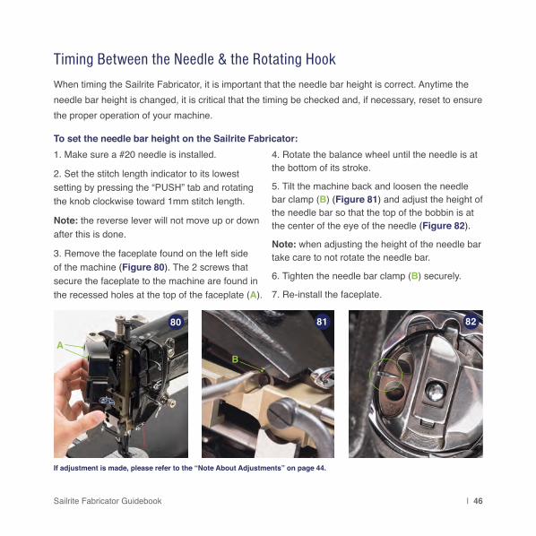
Timing Between the Needle & the Rotating Hook
To set the needle bar height on the Sailrite Fabricator:1. Make sure a #20 needle is installed.
2. Set the stitch length indicator to its lowest setting by pressing the “PUSH” tab and rotating the knob clockwise toward 1mm stitch length.
Note: the reverse lever will not move up or down after this is done.
3. Remove the faceplate found on the left side of the machine (Figure 80). The 2 screws that secure the faceplate to the machine are found in the recessed holes at the top of the faceplate (A).
4. Rotate the balance wheel until the needle is at the bottom of its stroke.
5. Tilt the machine back and loosen the needle bar clamp (B) (Figure 81) and adjust the height of the needle bar so that the top of the bobbin is at the center of the eye of the needle (Figure 82).
Note: when adjusting the height of the needle bar take care to not rotate the needle bar.
6. Tighten the needle bar clamp (B) securely.
7. Re-install the faceplate.
When timing the Sailrite Fabricator, it is important that the needle bar height is correct. Anytime the needle bar height is changed, it is critical that the timing be checked and, if necessary, reset to ensure the proper operation of your machine.
80 81 82
AB
If adjustment is made, please refer to the “Note About Adjustments” on page 44.

47 | Sailrite.com
To set the machine’s timing:1. Tilt the machine back and remove the slide plate by sliding it all the way to the left until it comes off of the machine (Figure 83).
2. Raise the presser feet and rotate the balance wheel until the needle is at the highest position. Remove the needle plate and the feed dog; each is held in place by two screws (Figure 84).
3. Ensure that the stitch length indicator is set to its lowest setting by pressing the “PUSH” tab and rotating the knob clockwise toward the 1mm stitch length (Figure 85).
83
84
85
NEEDLE PLATE SCREWS
FEED DOG SCREWS

Sailrite Fabricator Guidebook | 48
4. Rotate the balance wheel until the needle is at the bottom of its stroke.
5. Continue to rotate the balance wheel until the needle comes up 2.5mm from its lowest setting (Figure 88).
To do this, rotate the balance wheel so that the needle is at it’s lowest position. Make a mark on a paper 2.5mm from the edge. Hold the paper up to where the needle bar meets the machine casting and make a mark on the bar at the 2.5mm location (Figure 86).
Rotate the balance wheel until the mark lines up with the machine casting (Figure 87).
2.5mm
86
87
88
MARK

49 | Sailrite.com
89
90
91
HOOK
NEEDLE
GAP
A
6. The point of the hook should be lined up with the vertical centerline of the needle (Figure 89) and a very small gap of about 0.5mm should exist between the needle and the hook (Figure 90).
7. To adjust, rotate the balance wheel and loosen each of the 3 screws (A) holding the hook in place (Figure 91). Repeat steps 4 and 5 and set the hook so that the requirements in step 6 are met.
8. Tighten each of the 3 screws (A) holding the hook in place. Take care not to disturb the positioning of the hook. Go back and ensure each of these 3 screws are secure to ensure that the timing does not slip during machine usage.
9. Re-install the feed dog and needle plate taking care to center (left/right) the feed dog in the needle plate.
Note: Loosen the most convenient screw to access last when in the step 6 position. This one screw can be adjusted alone as timing is fine tuned. Be certain to tighten all three screws when the timing is perfect.

Sailrite Fabricator Guidebook | 50
The relationship of the two feet affects the ability of the machine to transition from thin to thick materials. If a foot is getting stuck on the fabric, adjustment may be necessary. Having the outside presser foot set at the recommended maximum height will improve feeding of varied thickness fabric assemblies.
Generally, for sewing heavy and medium weight fabrics, the outside presser foot height should be about 4mm and the height of the inside presser foot should be at about 2mm.
When the outside presser foot height is increased, the inside foot lift will decrease proportionately. Decreasing the height of the outside presser foot will increase the height of the inner foot and smooth the sewing/feeding operation.
To adjust the relationship between the two feet, lower the presser feet and rotate the balance wheel until the outside presser foot is in the upmost position. Next, loosen the screw for the crank (B) (there are 2 cranks about 4" apart and either one will make the adjustment). After loosening the screw, grab the outer presser foot and manually move it up or down as desired (set between 2mm and 4mm above the needle plate). Tighten the screw when done.
Adjusting the Presser Foot Lift 92
B

51 | Sailrite.com
Sailrite sets the outer presser foot at the maximum height. DO NOT further increase foot height or the machine will jam during operation.
The amount of lift of the outer presser foot is increased or decreased with pivot slide (A). When moved up, the range of movement of the presser foot is increased (lifts higher) allowing the machine to better feed applications with thickness transitions. Sliding the pivot down lowers the lift height and makes feeding smoother, which will help when sewing delicate fabrics.
Adjustment of the outer presser foot vertical lift with the pivot slide (A) will not affect the inside presser foot lift.
Sailrite does not recommend making this adjustment. If you believe this setting needs to be altered on your machine, please call and speak with a technician before making any changes.
Adjusting the Vertical Lift of the Outer Presser Foot
93
A

Sailrite Fabricator Guidebook | 52
1. Raise the presser foot and set the stitch length regulator to maximum (8mm). Turn the balance wheel to lower the needle into the hole of the feed dog and check to see if the needle is centered in the hole at the feed dog’s forward most position (B).
Note: If the needle if not centered in the Feed Dog hole (B), see page 45.
2. Keep turning the balance wheel until a full rotation is achieved. If the needle is still centered in the feed dog hole (B) throughout the movement, then the mechanism is timed properly. If it ends up in position (C), this indicates that the feed amount of the needle bar and presser foot is larger than that of the feed dog. To correct this, you will need to reduce distance (D). Use a wrench and loosen the nut. Slide the nut and its connected pivot block up. If the timing is off and the needle ends up at position (E), then the feed amount of the needle bar and presser foot is smaller than that of the feed dog. In this case, enlarge distance (D) as explained above but slide the nut down. Make adjustments until the needle arrives at (B) (the center of the feed dog hole at the end of the rotation).
Adjusting Feed Timing of the Needle Bar, Presser Foot and Feed Dog 94
95
D
CB
B
ESTITCH
LENG
TH
NEEDLE

53 | Sailrite.com
Set the machine to the longest stitch length possible (8mm) and tilt the machine so it is hinged back in the table.
Loosen screw (A) and (B), located on the shaft below the oil sump, and take out link pin (C) (Figure 96).
This will allow the length regulator (D) to pivot down (Figure 97) so that the slotted cam (E) can be accessed through the link pin hole (F). Loosen screw (G) to adjust the cam (E) with a small, standard screwdriver (H) (Figure 98).
Note: Hold the reverse lever down for better access to cam (E)
Turn the slotted cam clockwise to shorten the forward stitch length and lengthen the reverse stitch length. Turn the cam counterclockwise to lengthen the forward stitch length and shorten the reverse stitch length.
Reassemble the pivot by replacing the link pin (C) through the length regulator (D) and link (F)as it was before making the adjustment. The flat on the link pin shaft should face screw (A). Retighten all screws.
Note: Do not rotate the balance wheel while disassembled as it will disrupt the timing of the machine.
Stitch Length Adjustment Between Forward and Reverse
A
B C
E
H
G
96
97
98
D
F

Sailrite Fabricator Guidebook | 54
The normal sewing range of the thread take-up spring is 7/32" to 1/2". When sewing light weight materials with a short stitch length, decrease the spring tension and increase the travel of the spring to as much as 1/2". For sewing heavy weight materials, increase the spring tension and shorten its travel to as little as 7/32".
To adjust the travel of the thread take-up spring: Loosen set screw (I) and turn the complete tension assembly clockwise to increase the spring range (up to 1/2") or turn it counterclockwise to decrease the spring range (down to 7/32") (Figure 99).
Adjusting the Thread Take-Up Spring
I
7/32"
to 1/
2"
99
55 | Sailrite.com
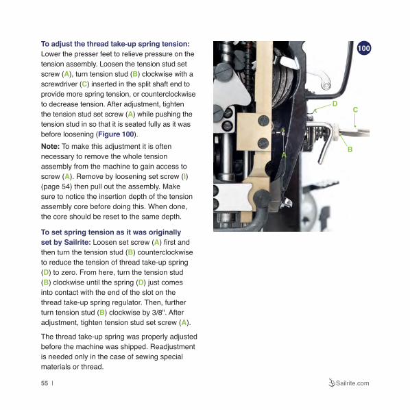
To adjust the thread take-up spring tension: Lower the presser feet to relieve pressure on the tension assembly. Loosen the tension stud set screw (A), turn tension stud (B) clockwise with a screwdriver (C) inserted in the split shaft end to provide more spring tension, or counterclockwise to decrease tension. After adjustment, tighten the tension stud set screw (A) while pushing the tension stud in so that it is seated fully as it was before loosening (Figure 100). Note: To make this adjustment it is often necessary to remove the whole tension assembly from the machine to gain access to screw (A). Remove by loosening set screw (I)(page 54) then pull out the assembly. Make sure to notice the insertion depth of the tension assembly core before doing this. When done, the core should be reset to the same depth.
To set spring tension as it was originally set by Sailrite: Loosen set screw (A) first and then turn the tension stud (B) counterclockwise to reduce the tension of thread take-up spring (D) to zero. From here, turn the tension stud (B) clockwise until the spring (D) just comes into contact with the end of the slot on the thread take-up spring regulator. Then, further turn tension stud (B) clockwise by 3/8". After adjustment, tighten tension stud set screw (A).
The thread take-up spring was properly adjusted before the machine was shipped. Readjustment is needed only in the case of sewing special materials or thread.
73
A
DC
B
100

Sailrite Fabricator Guidebook | 56
If your machine is skipping stitches the hook is not catching the thread consistently. This is usually because either the thread is not being held down by the fabric as the needle is withdrawn which does not allow for the loop of thread to be formed for the hook as it passes the needle, or the hook may not be passing the needle at the proper time. It may be passing the needle before a loop is formed or, at the opposite extreme, after the thread has been pulled upward out of the path of the hook.
Four Ways to Eliminate Skipped Stitches1) CHANGE THE NEEDLE: The first thing to do is simply change the needle. A bent needle will cause skipped stitches because the loop is not where the hook expects it to be. The needle could also have become covered with adhesive if you are using basting tape or sewing insignia cloth. In either case, the new needle will resolve these problems.
Also, make sure that the needle is in correctly (page 25), and check the upper thread path (page 33). The thread should pass from left to right through the needle eye.
2) ADJUST THE FOOT PRESSURE: Next, check for adequate foot pressure. Heavy, closely-woven materials like sailcloth and canvas can make the withdrawal of the needle from the fabric difficult. If the presser foot is lifting as the needle comes out of the cloth, the effect is the same as if the needle were not going far enough into the cloth. The loop that it forms will be too small. To solve this problem, more downward pressure must be placed on the feet (page 38).
3) RESET THE NEEDLE BAR HEIGHT: If skipped stitches continue to be a problem, the machine has most likely gone out of time. Check the height of the needle bar as described in “Timing Between the Needle and the Rotating Hook” on page 46.
4) CHECK THE TIMING: If the needle bar height is set properly and poor stitching still results, check the timing or the positioning of the hook. See “To set the machine’s timing” on page 47.
TROUBLESHOOTINGSkipped Stitches

57 | Sailrite.com
Lack of Stitch TensionRefer to the section titled “Adjusting Upper Tension Assemblies” and “Adjusting Bobbin Thread Tension” on pages 39-40. If adjustments still do not result in proper thread tension, move to the next larger needle and adjust the elongated thread guide (A) position as shown (Figure 101).
Material Thread Guide Position
Light (less tension)
Medium
Heavy (more tension)
101
102
A

Sailrite Fabricator Guidebook | 58
Fabricator SchematicsUnderstand the ins and outs of the Fabricator with
complete parts and systems schematics.
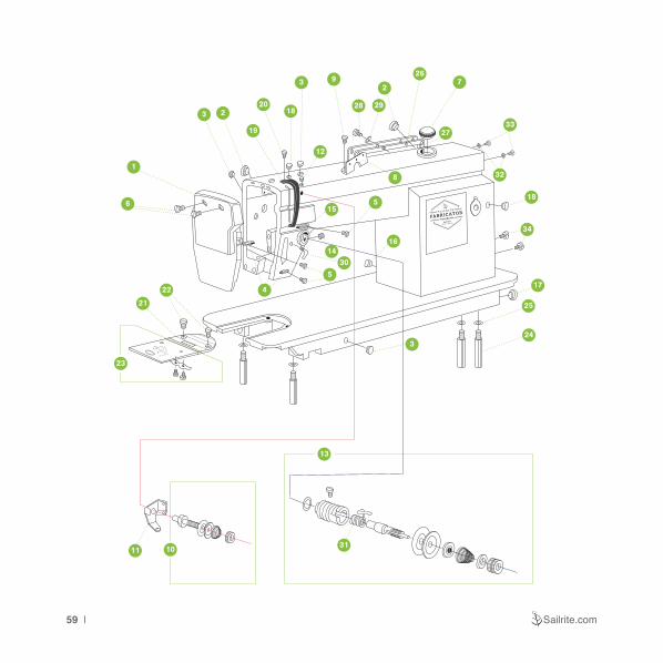
59 | Sailrite.com
3 2
19
2018
32
12
9
8
28 29
267
32
33
18
17
25
243
16
515
1430
5
54
1
6
22
21
23
13
311011
27
34

Sailrite Fabricator Guidebook | 60
Machine Arm and BedNo. Name Part#1. Face Plate ...............................................35T4-402a 2. Rubber Plug (19) .................................22T1-003C3 3. Rubber Plug (11.7) ...............................22T1-003C4 4. Thread Finger ......................................22T1-003C5 5. Screw for Thread Finger ......................22T1-003C6 6. Screw for Face Plate ................................22T1-004 7. Oil Window ................................................22T1-0088. Three Hole Thread Guide .........................36T2-004 9. Screw for Three Hole Thread Guide .........36T2-005 10. Small Thread Tension Assembly ..................104895 11. Thread Pass-by Plate ...........................36T2-006Dl 12. Screw for Small Tension Assembly ...........22T1-011 13. Large Thread Tension Assembly ..................10329714. Set Screw .................................................22T1-01315. Elongated Thread Finger ..........................22T1-01416. Rubber Plug (8.8) .....................................22T1-01517. Rubber Plug (27) ......................................22T1-016
No. Name Part#18. Rubber Plug (5.7) .....................................22T1-01719. Thread Take-up Lever Guard ....................33T4-00720. Lock Screw ...............................................22T2-00421. Needle Plate ................................................ 11074322. Screw for Needle Plate .............................22T1-02023. Slide Plate Assembly ...................................12062524. Bed Legs ................................................. 7WF4-01325. Washer .........................................................GB93 626. Back Cover ............................................. 5WF3-00227. Gasket for Back Cover ............................ 5WF3-00328. Screw for Back Cover ...............................22T1-00629. Washer for Back Cover .............................22T1-00730. Thread Guide ............................................35T4-40531. Thread Take Up Spring for Fabricator............2012932. Belt Cover Small Screw Washer ........... GB/T86 M433. Belt Cover Small Screw ........................ GB/T86 M334. Belt Cover Large Screw ....................... GB/T86 M5

61 | Sailrite.com
1818
18
18
12
3
4
56
24
7
24
8 9
10
30
3334
11
1213
12
12
25
25
14
32
31
15
16
1718
18
18
18
19
20
21
22
23
26
27
28
29
35

Sailrite Fabricator Guidebook | 62
Arm and Vertical Shafts, Needle bar Thread Take-up PartsNo. Name Part#1. Upper Shaft ...........................................4WF1-001A2. Rubber Bushing Plug ...........................22T3-001A23. Collar ...................................................22T3-002B14. Screw for Collar ...................................22T3-002B25. Front Bushing .......................................4WF1-006A6. Middle Bushing ........................................ 4WFI-0027. Screw for Middle Bushing ............................J0.0.408. Rear Bushing ............................................22T3-0059. Oil Seal for Rear Bushing ...................... 22T3-006F10. Stitch PRO Balance Wheel ..........................10716111. Feed Dog Lift Cam ...............................36T3-003D112. Screw for Cam .....................................36T3-003D213. Separating Cam Piece ..............................36T3-00414. Front Feed Link ................................... 22T3-09D1C15. Vertical Shaft ......................................... 15WF1-00116. Bevel Gear for Upper Shaft .......... 22T3-010E2a1-217. Upper Gear for Vertical Shaft ........ 22T3-010E2a2-218. Screw for Bevel Gears .........................22T2-005B3
No. Name Part#19. Bevel Gear for Lower Shaft ..........22T3-010E2b1-220. Lower Gear for Vertical Shaft ........22T3-010E2b2-221. Upper Bushing ........................................ 4WF1-00322. Lower Bushing ....................................... 33T1-023P23. Thread Take-up Lever Assembly ................3TI-023A24. Screw for Bushing/Cam ................... 61-04-01/B30825. Screw for Bushing ..........................................J0.0.526. Needle Bar ...................................................10250327. Needle Bar Thread Guide ............................10409928. Needle 135 x 17 (22) .........................................15329. Needle Screw ..............................................10301230. Posi-Pin Wheel Bushing for Fabricator ........12062431. Feed Cam ............................................ 36T5-008E132. Rear Feed Link .....................................4WF2-009A33. Posi-Pin Nut - Reverse Thread ....................10053634. Posi-Pin Quick Release Shaft ......................10204335. Set Screw for Posi-Pin Wheel Bushing ........713100

63 | Sailrite.com
12
3
4
5
6
7
8
9
1011 1213
13
1448
15
16
177
49
1819
20
21
22
23 24 2526
27
28
29
29
30
31
32 33
34
35
36
37
38
3940
41
42
43 44
4029
45
45
12
46
46
10
17
47
7

Sailrite Fabricator Guidebook | 64
Feed Dog Lift and Feed and Thread LoopingNo. Name Part#1. Feed Dog .....................................................1003872. Feed Dog Support ............................. 36T4-001A1a3. Washer for Feed Dog Support ................ 4WF2-0114. Eccentric Shaft for Feed Dog Support ..36T4-001A25. Screw ...........................................................J0.0.516. Feed Dog Support Crank ........................ 4WF2-0027. Screw for Feed ................................ 61-04-01/B5048. Positioning Screw .....................................22T2-0199. Feed Rock Shaft .......................................36T4-00210. Stop Ring ..............................................GB894.1 1511. Bushing for Feed Rock Shaft ....................22T6-004 12. Collar ...................................................22T3-002B113. Screw for Collar ...................................22T3-002B214. Feed Shaft Rear Crank ........................... 4WF2-00615. Link Pin for Feed Shaft Rear Crank ........................82T2-003C1a10-216. Screw for Link Pin ................................ 36T5-008E517. Screw for Crank ...................................22T6-008D318. Bobbin Case ................................................10074219. Bobbins (Style M) ........................................ 65112320. Rotary Hook ................................................. 11074221. Lower Shaft ..........................................36T4-008D122. End Screw for Lower Shaft .............. 22T4-001A1a123. Plug for End Screw .......................... 22T4-001A1a224. Oil Seal for Front Lower Shaft ..................22T4-003
No. Name Part#25. Front Lower Shaft Bushing ....................... 4WF1-0526. Oil Regulating Screw for Hook ..................22T4-00527. Spring for Oil Regulating Screw ................22T4-00628. Collar for Lower Shaft ..........................22T4-002B129. Screw for Lower Feed ..................................J0.0.3530. Rear Lower Shaft Bushing ...................... 4WF1-00431. Oil Tube Connector ..............................22T4-007C232. Plunge for Rear Lower Shaft ....................36T4-01533. Spring for Rear Lower Shaft .....................36T4-01634. Stopper for Rear Lower Shaft ...................22T4-01035. Washer .........................................................GB93 636. Screw for Stopper .....................................22T9-00637. Hinge Pin for Feed Lift Rear Crank ...........22T6-00738. Feed Lift Rear Crank .............................. 4WF2-00339. Feed Lift Shaft Bushing ............................22T6-01240. Washer for Feed Lift & Rock Shaft ...........51T5-01341. Feed Lift Fork ................................... 36T4-018H10142. Feed Lift Shaft .....................................36T4-018H243. Position Bracket ...........................................10447644. Screw for Position Bracket ........................22T4-01545. Screw for Front & Rear Bushing ..................J0.0.0546. Screw for Collar ...................................22T3-002B247. Oil Wick ...............................................22T6--008D348. Feed Shaft Front Crank .......................... 5WF4-00249. Screw for Link ...................................... 36T5-008E3

65 | Sailrite.com
2 • 3 • 4 •• 5 •• 6 •
• 7
•• 8 •••
PUSH
1
28
3
4
8
5
6
7
18
18
2423
4241 25
26
2221
20
19
164
10
15
14
9
1211
13
32
30
29
31
33
3937
34
3538
40
36
2
27
40

Sailrite Fabricator Guidebook | 66
Feed MechanismNo. Name Part#
1. Link Pin for Stitch Length Bracket ...........4WF2-012
2. Stitch Length Bracket ..............................7WF2-012
3. Screw for Stitch Length Link Pin .............. 20T2-031
4. Screw for Stitch Length ....................... 22T5-010D4
5. Bushing for Stitch Length Bracket Shaft .5WF1-003
6. Shaft for Stitch Length Bracket ................ 22T5-004
7. Rubber Plug (18) .....................................36T5-003
8. Screw for Bushing ......................................... J0.0.5
9. Reverse Feed Lever Crank .....................7WF2-009
10. Reverse Feed Lever Crank Shaft ....22T5-012E1a1
11. Spring for Reverse Feed Lever Crank .... 1KT3-002
12. Screw for Reverse Feed Lever Crank ..... 22T5-013
13. Reverse Feed Lever ............................ 4WF2-007A
14. Pin Shaft for Reverse Feed Lever .... 22T5-010D2a
15. O-type Ring for Reverse Feed Lever Pin Shaft ...................... GB345 2.1 6.3x1.8G
16. Screw for Reverse Feed Lever ........... 22T5-010D3
17. Screw Bolt for Stitch Length ............... 36T5-007D1
18. O-type Rubber Ring for Screw Bolt ..... 33T2-030-A
19. Stitch Dial Wheel ................................ 36T5-007D2
20. Stitch Dial Face .................................... 4WF2-004A
21. Bushing for Stitch Dial ........................ 36T5-007D4
No. Name Part#22. Screw for Stitch Dial ........................... 36T5-007D523. Stop Pin for Stitch Dial ............................. 36T5-01224. Spring for Stitch Dial Stop Pin ................. 22T5-00925. Screw for Cam .................................... 36T3-003D226. Feed Cam ............................................36T5-008E127. Rear Feed Link ....................................4WF2-009A28. Stitch Adjusting Link ............................. 4WF2-009B29. Pin for Rear Feed Link .................................. 1a10-I30. Link for Rear Feed Link ................ 36T5-008E4H0231. Screw for Link Pin ................................36T5-008E532. Link for Stitch Length Adjusting Crank ............................36T5-008E4H0133. Pin for Stitch Length Adjusting Crank Link ............................36T5-008E634. Screw for Stitch Length Crank Link Pin .....................................36T5-008E735. Screw for Stitch Length Slotted Cam ...36T5-008E836. Stitch Length Slotted Cam ...................36T5-008E937. Stitch Length Adjusting Crank .............36T5-008EI038. Left Set Pin ..............................................5WFI-00239. Right Set Pin ............................................5WFI-00140. Screw for Crank .................................. 22T6-008D341. Stitch Length Push Lever ......................... 36T5-01142. Spring for Stitch Dial ................................36T5-010

67 | Sailrite.com
24
23
19
229
8
1612
14
13
15
6
52
1
4
3
18
17
21
25 26
8
7
11
10
20
27

Sailrite Fabricator Guidebook | 68
Presser FootNo. Name Part#1. Presser Foot Lift ....................................... 33T-0032. Screw for Presser Foot Lift ...................... 22T1-0113. Presser Foot Lift Cam .............................4WF3-0024. Oil Seal for Presser Foot Lift Cam .......22T7-004B15. Presser Foot Lift Lever ..................... 22T7-004B1b6. Thread Releasing Cam ..................... 22T7-004B1c7. Screw for Presser Foot Lift Lever ....... 22T7-004B28. Screw for Knee Lifter Draw Bar .......... 22T7-004B39. Knee Lift Draw Bar ................................ 22T7-005A10. Screw for Thread Releasing Cam ............ 22T7-00611. Thread Releasing Pin ..............................35T3-30512. Knee Lift Lever .................................... 22T7-007C213. Spring for Knee Lift Lever .......................4WF3-00114. Knee Lift Connecting Rod ....................... 1KT4-006
No. Name Part#15. Pin for Knee Lift Lever Spring ............... 22T7-005B16. Pivot Screw for Knee Lift Lever ............... 35T3-30317. Bushing for Outer Presser Bar ................. 34T3-30518. Presser Bar for Outer Foot ...................... 35T3-30219. Presser Bar Lift Block ..............................35T3-30120. Screw for Presser Bar Lift Block .............. 22T2-01321. Screw for Outer Presser Bar Bushing ...... 34T3-30222. Tension Spring for Outer Presser Bar ...... 34T3-30123. Outer Foot Presser Regulating Thumb Screw .......................................... 1KT4-00124. Nut for Outer Presser Regulating Thumb Screw .......................................... 1KT4-00225. Screw for Outer Presser Foot ......... 61-04-01/B31626. Outer Presser Foot ..................................35T3-30427. Lock Screw for Bushing/Cam ..........61-04-01/B308

69 | Sailrite.com
1
2
3
4
5
14
9
12
31
1350
49
1547
8
10
7
40
24
26
4445
42
41
46
24
37
515255
53
24
21
4023
39 38 36
15 16 1720
22
24
2833
24
34
32 35
11
31
30
29
2326
25
27
21252318
19
6
56
33
54
43
48

Sailrite Fabricator Guidebook | 70
Upper Feed PartsNo. Name Part#
1. Inner Foot Regulating Thumb Screw .....................35T5-503
2. Nut for Inner Foot Regulating Thumb Screw .........34T5-503
3. Tension Spring for Inner Foot Bar ..........................35T5-501
4. Screw for Needle Bar Bracket Pivot Pin ................... J0.0.40
5. Pivot Pin for Needle Bar Bracket ...........................35T5-504
6. Reel for Tension Spring .........................................35T5-505
7. Link for Inner Foot Bar ...........................................35T5-507
8. Presser Bar for Inner Foot .....................................35T5-508
9. Sliding Box for Inner Foot Bar...............................6WF5-002
10. Sliding Block for Inner Foot Bar .............................33T1-013
11. Screw for Upper Needle Motion Link ...................34T5-513b
12. Positioning Screw ..................................................22T2-019
13. Sliding Box for Needle Motion Bracket .................. 35T5-511
14. Needle Bar Motion Frame.....................................6WF5-001
15. Nut for Inner Foot Bar Feed ...................................34T5-518
16. Washer for Inner Foot Bar Feed Nut .....................34T5-519
17. Link for Inner Foot Eccentric Cam .........................34T5-520
18. Inner Foot Eccentric Cam ......................................34T5-516
19. Set Screw ..............................................................22T1-013
20. Washer for Needle Motion Components ................34T5-521
21. Rear Bushing for Upper/Lower Needle Motion ....34T5-538a
22. Upper Rear Needle Motion Crank .........................34T5-517
23. Screw for Needle Motion Cranks ...........................34T5-540
24. Screw for Bushing/Cam ................................ 61-04-01/B308
25. Oil Felt For Upper Needle Motion Bushings ........34T5-536b
26. Front Bushing for Upper/Lower Needle Motion ...34T5-536a
27. Upper Needle Motion Shaft ...................................34T5-537
28. Screw for Needle Motion Components ..................34T5-522
No. Name Part#
29. Front Needle Motion Shaft Crank ..........................34T5-535
30. Link for Upper Needle Motion Shaft.......................34T5-534
31. Screw for Forward Needle Motion Links ................34T5-507
32. Presser Foot Lift Plate ...........................................35T5-506
33. Nut for Forward Needle Motion Links ....................34T5-508
34. Presser Bar Lift Block ............................................35T3-301
35. Screw for Presser Foot Lift Plate ...........................34T5-527
36. Lower Needle Bar Motion Shaft .............................34T5-539
37. Screw for Lower Rear Needle Motion Crank .........17T4-002
38. Lower Rear Needle Motion Shaft Crank ...............5WF4-004
39. Nut for Lower Rear Needle Motion Crank ................ J0.0.63
40. Oil Felt for Lower Needle Motion Bushings .........34T5-538b
41. Collar for Lower Needle Motion Shaft ....................34T5-532
42. Screw for Collar ................................................ 22T3-002B2
43. Lower Front Needle Motion Crank .........................34T5-533
44. Screw for Lower Front Needle Motion ...................34T5-541
45. Sliding Block for Needle Motion Fork.....................34T5-531
46. Fork Lever for Needle Motion ................................34T5-529
47. Pin for Needle Motion Fork Lever ..........................34T5-530
48. Link for Lower Needle Motion Shaft.......................35T5-512
49. Inner Presser Foot .................................................35T5-502
50. Lock Screw ............................................................22T2-004
51. Link for Feed Shaft Front Crank ...........................5WF4-003
52. Screw for Link ....................................................36T5-008E3
53. Screw for Feed ............................................. 61-04-01/B504
54. Connecting Pin for Feed Shaft Front Crank..........5WF4-001
55. Feed Shaft Front Crank ........................................5WF4-002
56. Screw for Needle Bar Motion Fork Lever.............34T5-513a

71 | Sailrite.com
1
2
3
5
6
4
7
818
9
10
11
13
14
19
15
16
12
18
17
9
4
4

Sailrite Fabricator Guidebook | 72
Oil PumpNo. Name Part#1. Oil Pump ...............................................15WF4-0032. Large Gear for Oil Pump .......................15WF4-0063. Small Gear for Oil Pump .......................15WF4-0074. Screw for Oil Filter ..........................GB/T67 M3X105. Washer for Oil Regulating Plate .................. GB93 46. Cover for Oil Pump ...............................15WF4-0047. Oil Regulating Plate ................................. 22T8-0078. Oil Filter .................................................22T8-008A9. Screw for Oil Pump .................................. 22T8-00910. Lower Oil Pipe ........................................4WF4-005
No. Name Part#11. Oil Wick Plate .......................................... 33T4-01812. Screw for Oil Wick Plate .......................... 22T8-01213. Upper Oil Pipe .......................................22T8-013D14. Oil Tube ................................................... 22T8-01415. Oil Tube Felt ............................................ 22T8-01516. Clamp for Oil Felt Tube ............................ 22T8-01617. Shaft for Large Oil Pump Gear .............15WF4-00518. Screw for Oil Pump Cover ..............GB/T68 M3X1019. Screw for Oil Tube Felt Clamp ................. 20T4-006

73 | Sailrite.com
25
21
31
20
27
26
22
33
32
30
11
5
14
16 171518
6
19
7
8
9
1025
1
24
23
2829
12
2
34
13

Sailrite Fabricator Guidebook | 74
Oil Reservoir & AccessoriesNo. Name Part#1. Oil Tray ...................................................4WF5-0012. Screw for Oil Tray Drain ...................... 22T9-001A23. Washer Oil Tray Drain Screw .............. 22T9-001A34. Gasket for Oil Tray .................................. 2KT9-0085. Hinge Shaft for Knee Lift ..................... 22T9-001A66. Spring for Knee Lift Stop Bracket ....... 22T9-001A77. Knee Lift Stop Bracket ........................ 22T9-001A88. Screw for Knee Lift Stop Bracket ........ 22T9-001A99. Nut for Knee Lift Stop Bracket Screw .22T9-001A1010. Stop Bracket Attachment Screw .............. 22T9-03611. Knee Lift Post Connector ........................4WF5-00212. Knee Lift Connector ............................ 22T9-003B313. Screw for Knee Lift Connector ..................GB/T5781 M6X12 M6X2014. Bent Rod for Knee Lift ........................ 22T9-003B215. Knee Lift Plate .................................... 22T9-003B516. Knee Lift Bracket ................................ 22T9-003B617. Screw for Knee Lift Bracket ................ 22T9-003B7
No. Name Part#18. Pad for Knee Lift Plate ........................ 22T9-003B819. Stop Ring for Knee Lift Hinge Pin ............. GB896 920. Belt Cover for Professional & Fabricator .....12061621. Bobbin Winder ............................................ 10327622. Thread Stand .............................................14F0-0023. Oil Jug ......................................................22T9-017 Refill Oil for Sewing Machines ...................... 2380024. Magnet for Oil Tray ..................................22T9-01225. Oil Spout ..................................................33TF-01126. Front Corner Cushion ....................................... 42927. Back Corner Cushion ........................................ 43828. Machine Hinge .....................................22T9-007F129. Rubber Cushion for Machine Hinge .....22T9-007F230. Bobbins (Style M) ........................................65112331. Timing Belt ...................................................12058032. Wood Screw for Bobbin Winder ..GB5282 ST4.8X1933. Washer for Bobbin Winder Screw ............ GB/T95 6
75 | Sailrite.com
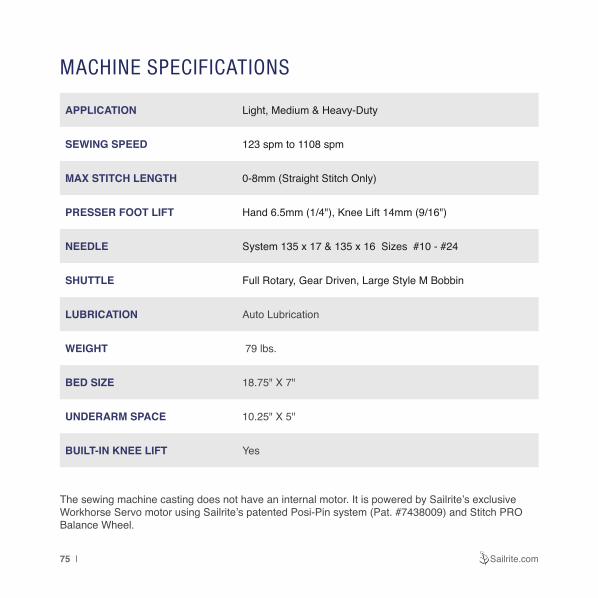
MACHINE SPECIFICATIONS
APPLICATION Light, Medium & Heavy-Duty
SEWING SPEED 123 spm to 1108 spm
MAX STITCH LENGTH 0-8mm (Straight Stitch Only)
PRESSER FOOT LIFT Hand 6.5mm (1/4"), Knee Lift 14mm (9/16")
NEEDLE System 135 x 17 & 135 x 16 Sizes #10 - #24
SHUTTLE Full Rotary, Gear Driven, Large Style M Bobbin
LUBRICATION Auto Lubrication
WEIGHT 79 lbs.
BED SIZE 18.75" X 7"
UNDERARM SPACE 10.25" X 5"
BUILT-IN KNEE LIFT Yes
The sewing machine casting does not have an internal motor. It is powered by Sailrite’s exclusive Workhorse Servo motor using Sailrite’s patented Posi-Pin system (Pat. #7438009) and Stitch PRO Balance Wheel.

Sailrite Fabricator Guidebook | 76
ALL PARTS & LABOR ARE FULLY GUARANTEED FOR 2 YEARS BY SAILRITE.
We are proud to provide you with everything you need to successfully maintain and repair your Fabricator Sewing Machine. Should you choose to return your machine for repairs, you will be responsible for delivery both ways.
PLEASE NOTE:Damage due to improper use or neglect, impact damage and normal wear from use of the sewing machine as well as sacrificial components and notions (needles, needle plate, feed dog, rotary hook, bobbins and belt) are not covered under this warranty.
2-Year Limited Warranty

120652*1
Sailrite Fabricator Guidebook
V-1
Equipping you to sew at home & on the water.
Copyright ©2017
Fabricator Patented Technology: #7438009