settlement evaluation of spread foundations on heavily
TRANSCRIPT
Annals of Warsaw University of Life Sciences – SGGWLand Reclamation No 43 (2), 2011: 113–120(Ann. Warsaw Univ. of Life Sci. – SGGW, Land Reclam. 43 (2), 2011)
Settlement evaluation of spread foundations on heavily preconsolidated cohesive soils
ZBIGNIEW LECHOWICZ, SIMON RABARIJOELY, PAWEŁ GALAS, DARIUSZ KIZIEWICZDepartment of Geotechnical Engineering, Warsaw University of Life Sciences – SGGW
Abstract: Settlement evaluation of spread founda-tions on heavily preconsolidated cohesive soils. The paper presents the results of fi eld and labora-tory tests performed on the heavily preconsolidat-ed boulder clays which prevail on the campus of the Warsaw University of Life Sciences – SGGW as foundation layers. Based on the results of fi eld and laboratory tests a problem of spatial variability assessment of the thickness of foundation layers and the soil parameters is discussed. Special atten-tion is drawn to the selection of the design values of oedometer moduli and the suitability of calcula-tion methods for settlement evaluation. Calculated settlements were approved by the fi eld measure-ments performed during building construction.
Key words: spread foundations, Eurocode 7, Ser-viceability Limit States, cohesive soils.
INTRODUCTION
In Eurocode 7 a distinction is made be-tween ultimate limit states and service-ability limit states (EN 1997-1 Eurocode 7 Part 1). Generally, limit state design codes devote more attention to ultimate limit states (ULSs) than to serviceability limit states (SLSs) (Orr and Farrell 1999; 2001; Orr 2005; Bond and Harris 2008). In case of serviceability limit states the estimation of settlements and differential settlements is a fundamental aspect of the design of shallow foundations (Poulos et al. 2001; Frank et al. 2004; Simpson et al.
2009). In many geotechnical designs, the size of pad or strip footings is determined by SLS rather than by ULS requirements particularly when building with basement is founded on preconsolidated clays.
The paper presents the results of fi eld and laboratory tests performed on the hea-vily preconsolidated boulder clays which prevail on the campus of the Warsaw Uni-versity of Life Sciences – SGGW as foun-dation layers. Based on the results of fi eld and laboratory tests a problem of spatial variability assessment of the thickness of foundation layers and the soil parameters is discussed. Special attention is drawn to the selection of the design values of oedometer moduli and the suitability of calculation methods for settlement evalu-ation. In order to evaluate differential set-tlements the numerical calculations were performed using the fi nite element pro-gram Sage-Crisp based on the Modifi ed Cam-Clay model. Calculated settlements were approved by the fi eld measurements performed during building construction.
DESCRIPTION OF THE TEST SITE
The test site is located at the campus of the Warsaw University of Life Sciences where in last ten years several new buildings were
10.2478/v10060-008-0097-z
114 Z. Lechowicz et al.
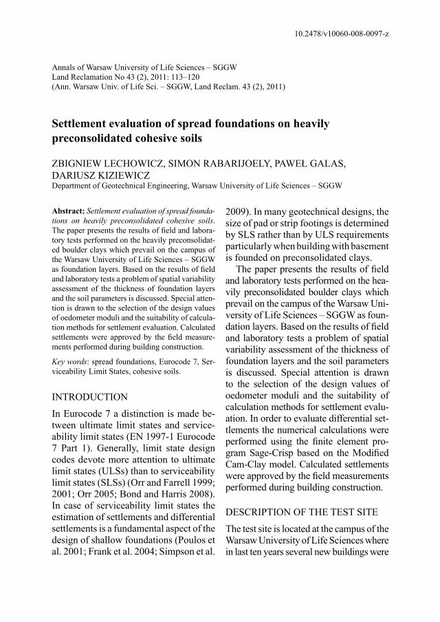
constructed. An example is building No 37 in plan 120 m × 57 m with the basement (B) and fi ve-fl oors (5F) (Fig. 1). Due to expected differential settlements building was constructed as three dilated parts (Fig. 2).
In each side part two halls with two fl oors height were located. In the rest of the building the structural loads varying between 5–12 MN were transmitted by the columns with 7.8 m spacing to the ground by pad footings. Rectangular pad footings were designed with size from
3.4 m × 3.4 m up to 6.5 m × 6.5 m. Pad footings with size 3.4 m × 3.4 m which cause unit loads about 633 kPa taking in account eccentric loading on footing are considered in this paper.
FIELD AND LABORATORY TESTS
In general the tested subsoil with the exception of 2–3 m of surface layers consists of moraine deposits underlain by fi ne sand layer. Moraine Quaternary deposits consist of two layers – brown
FIGURE 1. View of the building No 37 at the campus of the Warsaw University of Life Sciences – SGGW
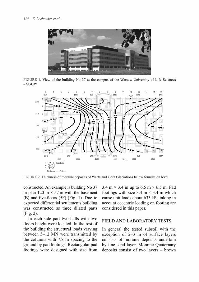
FIGURE 2. Thickness of moraine deposits of Warta and Odra Glaciations below foundation level
Settlement evaluation of spread foundations... 115
boulder clay of Warta Glaciation and grey boulder clay of Odra Glaciation. Index properties of boulder clays are presented in the Table 1. Tested soils can be classifi ed as preconsolidated low plasticity sandy lean clays CL according to ASTM D.2487 and saCL or sasiCL (ISO 14688–2).
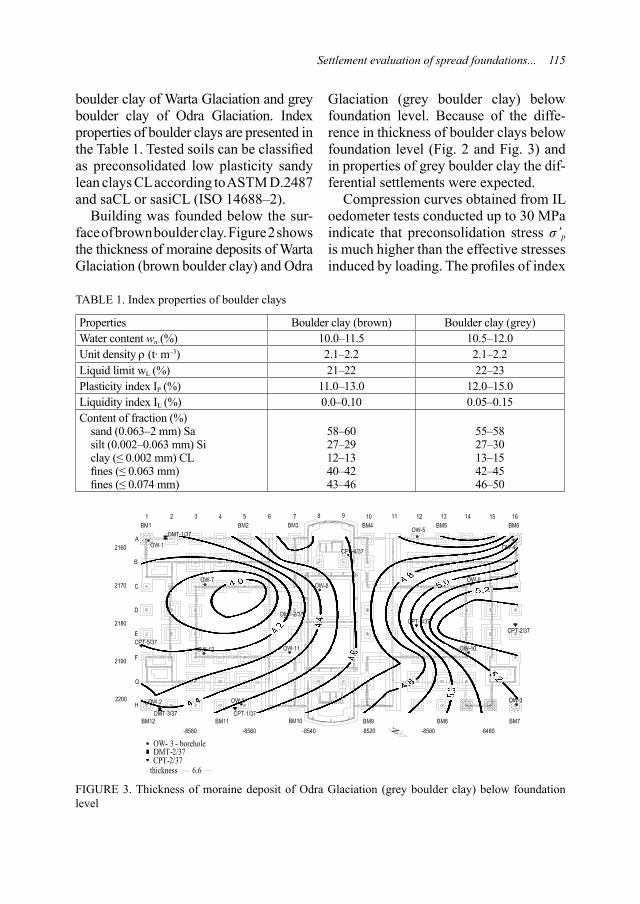
Building was founded below the sur-face of brown boulder clay. Figure 2 shows the thickness of moraine deposits of Warta Glaciation (brown boulder clay) and Odra
Glaciation (grey boulder clay) below foundation level. Because of the diffe-rence in thickness of boulder clays below foundation level (Fig. 2 and Fig. 3) and in properties of grey boulder clay the dif-ferential settlements were expected.
Compression curves obtained from IL oedometer tests conducted up to 30 MPa indicate that preconsolidation stress σ’p is much higher than the effective stresses induced by loading. The profi les of index
FIGURE 3. Thickness of moraine deposit of Odra Glaciation (grey boulder clay) below foundation level
TABLE 1. Index properties of boulder clays
Properties Boulder clay (brown) Boulder clay (grey)Water content wn (%) 10.0–11.5 10.5–12.0Unit density ρ (t· m–3) 2.1–2.2 2.1–2.2Liquid limit wL (%) 21–22 22–23Plasticity index IP (%) 11.0–13.0 12.0–15.0Liquidity index IL (%) 0.0–0.10 0.05–0.15Content of fraction (%)
sand (0.063–2 mm) Sasilt (0.002–0.063 mm) Siclay (≤ 0.002 mm) CLfi nes (≤ 0.063 mm)fi nes (≤ 0.074 mm)
58–6027–2912–1340–4243–46
55–5827–3013–1542–4546–50
116 Z. Lechowicz et al.
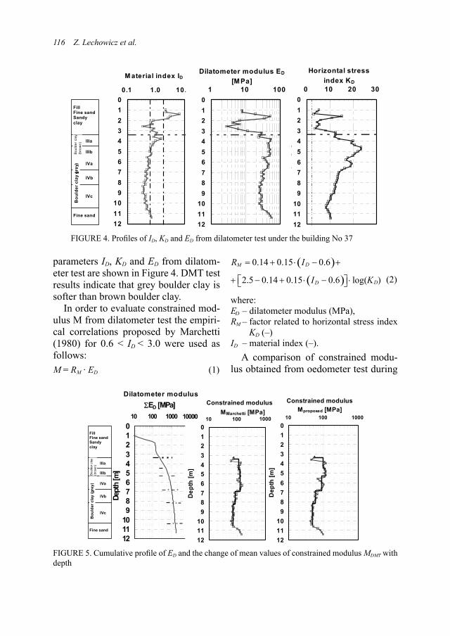
parameters ID, KD and ED from dilatom-eter test are shown in Figure 4. DMT test results indicate that grey boulder clay is softer than brown boulder clay.
In order to evaluate constrained mod-ulus M from dilatometer test the empiri-cal correlations proposed by Marchetti (1980) for 0.6 < ID < 3.0 were used as follows:M = RM · ED (1)
( )0.14 0.15 0.6DMR I= + ⋅ − +
( )2.5 0.14 0.15 0.6 log( )DDI K+ ⎡ − + ⋅ − ⎤ ⋅⎣ ⎦ (2)
where:ED – dilatometer modulus (MPa), RM – factor related to horizontal stress index
KD (–)ID – material index (–).
A comparison of constrained modu-lus obtained from oedometer test during
FIGURE 4. Profi les of ID, KD and ED from dilatometer test under the building No 37
Fill Fine sand Sandy clay
Bou
lder
cla
y (b
row
n) IIIa
IIIb
Bou
lder
cla
y (gr
ey) IVa
IVb
IVc
Fine sand
0123456789
101112
0.1 1.0 10.0
M aterial index ID
0123456789
101112
0 10 20 30
Horizontal stress index KD
Dep
th [m
]
0123456789
101112
1 10 100
Dilatometer modulus ED
[MPa]
FIGURE 5. Cumulative profi le of ED and the change of mean values of constrained modulus MDMT with depth
0123456789
101112
10 100 1000 10000
Dilatometer modulus ED [MPa]
Dept
h [m
]
0123456789
101112
10 100 1000
Constrained modulus MMarchetti [MPa]
Dep
th [m
]
0123456789
101112
10 100 1000
Constrained modulus Mproposed [MPa]
Dep
th [m
]
Fill Fine sand Sandy clay
Bou
lder
cla
y (b
row
n) IIIa
IIIb
Bou
lder
cla
y (g
rey)
IVa
IVb
IVc
Fine sand
1000
Dilatometer modulus
100000
Constrained modulus
Settlement evaluation of spread foundations... 117
reloading indicates that for interpretation of dilatometer tests in boulder clays the following relation can be used:
RM = 0.14 + 1.6 · log KD (3)
In Figure 5, the profi les of cumulative values of dilatometer modulus ED as well as constrained modulus M obtained from Marchetti formulae and from proposed formula are shown with mean values of constrained modulus calculated for sublayers separated based on cumulative curve of ED.
SETTLEMENT ANALYSIS
During the building construction the settlement gauges (BM 1–BM 12) were installed on the selected columns of three dilated parts of the building No 37 (Fig. 2). The measurements of settlements were started after the completion of second fl oor (2F). The settlement measurements proved that the displacements of three dilated parts were different. The settlement gauges installed in the middle part and left part under loading caused by the second stage of building construction (3F–5F) were 3–6 mm but in the right part 8–10 mm. In the paper the results of settlement
calculation for selected footings in the right part are presented.
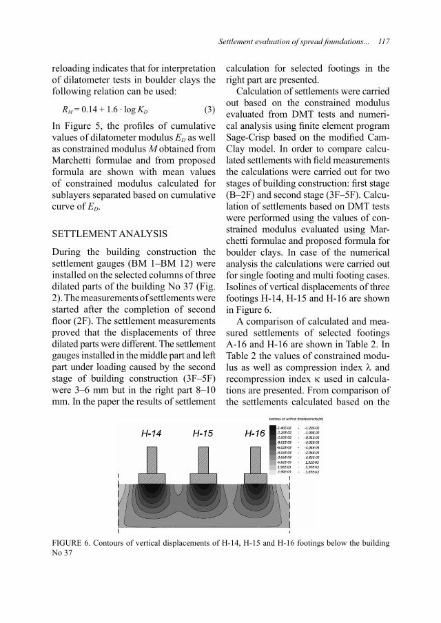
Calculation of settlements were carried out based on the constrained modulus evaluated from DMT tests and numeri-cal analysis using fi nite element program Sage-Crisp based on the modifi ed Cam-Clay model. In order to compare calcu-lated settlements with fi eld measurements the calculations were carried out for two stages of building construction: fi rst stage (B–2F) and second stage (3F–5F). Calcu-lation of settlements based on DMT tests were performed using the values of con-strained modulus evaluated using Mar-chetti formulae and proposed formula for boulder clays. In case of the numerical analysis the calculations were carried out for single footing and multi footing cases. Isolines of vertical displacements of three footings H-14, H-15 and H-16 are shown in Figure 6.
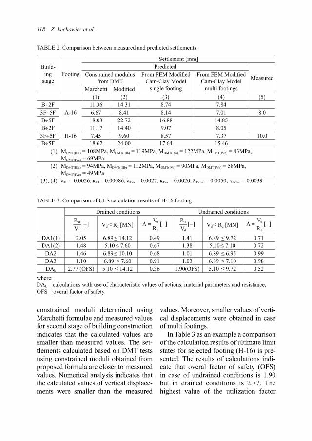
A comparison of calculated and mea-sured settlements of selected footings A-16 and H-16 are shown in Table 2. In Table 2 the values of constrained modu-lus as well as compression index λ and recompression index κ used in calcula-tions are presented. From comparison of the settlements calculated based on the
FIGURE 6. Contours of vertical displacements of H-14, H-15 and H-16 footings below the building No 37
118 Z. Lechowicz et al.
constrained moduli determined using Marchetti formulae and measured values for second stage of building construction indicates that the calculated values are smaller than measured values. The set-tlements calculated based on DMT tests using constrained moduli obtained from proposed formula are closer to measured values. Numerical analysis indicates that the calculated values of vertical displace-ments were smaller than the measured
values. Moreover, smaller values of verti-cal displacements were obtained in case of multi footings.
In Table 3 as an example a comparison of the calculation results of ultimate limit states for selected footing (H-16) is pre-sented. The results of calculations indi-cate that overal factor of safety (OFS) in case of undrained conditions is 1.90 but in drained conditions is 2.77. The highest value of the utilization factor
TABLE 2. Comparison between measured and predicted settlements
Build-ing
stageFooting
Settlement [mm]Predicted
MeasuredConstrained modulus from DMT
From FEM Modifi ed Cam-Clay Model
single footing
From FEM Modifi ed Cam-Clay Model
multi footingsMarchetti Modifi ed(1) (2) (3) (4) (5)
B÷2FA-16
11.36 14.31 8.74 7.843F÷5F 6.67 8.41 8.14 7.01 8.0B÷5F 18.03 22.72 16.88 14.85B÷2F
H-1611.17 14.40 9.07 8.05
3F÷5F 7.45 9.60 8.57 7.37 10.0B÷5F 18.62 24.00 17.64 15.46
(1) MDMT(IIIa) = 108MPa, MDMT(IIIb) = 119MPa, MDMT(IVa) = 122MPa, MDMT(IVb) = 83MPa, MDMT(IVc) = 69MPa
(2) MDMT(IIIa) = 94MPa, MDMT(IIIb) = 112MPa, MDMT(IVa) = 90MPa, MDMT(IVb) = 58MPa, MDMT(IVc) = 49MPa
(3), (4) λIII = 0.0026, κIII = 0.00086, λIVa = 0.0027, κIVa = 0.0020, λIVb-c = 0.0050, κIVb-c = 0.0039
TABLE 3. Comparison of ULS calculation results of H-16 footing
Drained conditions Undrained conditionsd
d
R [ ]V
− Vd ≤ Rd [MN]d
d
V [ ]R
Λ = − d
d
R [ ]V
− Vd ≤ Rd [MN]d
d
V [ ]R
Λ = −
DA1(1) 2.05 6.89 ≤ 14.12 0.49 1.41 6.89 ≤ 9.72 0.71DA1(2) 1.48 5.10 ≤ 7.60 0.67 1.38 5.10 ≤ 7.10 0.72
DA2 1.46 6.89 ≤ 10.10 0.68 1.01 6.89 ≤ 6.95 0.99DA3 1.10 6.89 ≤ 7.60 0.91 1.03 6.89 ≤ 7.10 0.98DAk 2.77 (OFS) 5.10 ≤ 14.12 0.36 1.90(OFS) 5.10 ≤ 9.72 0.52
where:DAk – calculations with use of characteristic values of actions, material parameters and resistance,OFS – overal factor of safety.

Settlement evaluation of spread foundations... 119
Λ in case of undrained conditions was obtained from DA2 and DA3 and in case of drained conditions the highest value of Λ was from DA3.
CONCLUSIONS
The results of fi eld and laboratory inves-tigations indicate that differential set-tlements of the building founded on the heavily preconsolidated clays was mainly caused by the spatial variability of the thickness and the difference in compres-sibility of brown and grey boulder clays below foundation level. A comparison of calculated and measured settlements shows that the settlement calculated based on constrained moduli determined using Marchetti formulae are smaller than measured values. A better agreement between calculated and measured settle-ments was obtained in case of settlements calculated based on constrained moduli obtained from proposed formula.
AcknowledgmentsThis research was supported by two Grants No N N506 395135 and No N N506 432436 from the Ministry of Science and Higher Education, Warsaw, Poland.
REFERENCESBOND A., HARRIS A. 2008: Decoding Eurocode
7. Taylor&Francis. London.EN 1997-1 Eurocode 7 2004: Geotechnical De-
sign – Part 1: General Rules, CEN, Brussels. FRANK R., BAUDUIN C., DRISCOLL R., KA-
VVADAS M., KREBS OVESEN N., ORR T., SCHUPPENER B. 2004: Designers’ Guide to EN 1997-1, Eurocode 7. Geotechnical design – General rules. Thomas Telford, London.
International Standard ISO 14688-2. 2004: Geo-technical investigation and testing – Identifi ca-
tion and classifi cation of soil – Part 2: Princi-ples for a classifi cation.
MARCHETTI S. 1980: In Situ Tests by Flat Dila-tometer, Journal of the Geotechnical Enginee-ring Division, ASCE, Vol. 106, No GT3, Proc. Paper 15290, 299–321.
ORR T.L.L. 2005: Evaluation of Eurocode 7. Proceedings of the International Workshop on the Evaluation of Eurocode 7. Trinity College, Dublin.
ORR T.L.L., FARRELL E.R. 1999: Geotechnical Design to Eurocode 7, Springer, London.
ORR T.L.L., FARRELL E.R. 2001: Use of servi-ceability limit state calculations in geotechni-cal design. Proceedings 15th International Con-ference on Soil Mechanics and Geotechnical Engineering, Istanbul, Vol. 1, 821–824.
POULOS H.G., CARTER J.P., SMALL J.C. 2001: Foundations and retaining structures – Research and practice. Proceedings 15th International Conference on Soil Mechanics and Geotechni-cal Engineering, Istanbul, Vol. 4, 2527–2606.
SIMPSON B., MORRISON P., YASUDA S., TOWNSEND B., GAZETAS G. 2009: State of the art report. Analysis and design. Pro-ceedings 17th International Conference on Soil Mechanics and Geotechnical Engineering, Ale-xandria, Vol. 4, 2873–2929.
Streszczenie: Ocena osiadań fundamentów bezpośrednich posadowionych na prekonsolid-owanych gruntach spoistych. Projektowanie bu-dynków z użytkową częścią podziemną stwarza często warunki bezpośredniego posadowienia fundamentów na występujących w podłożu silnie prekonsolidowanych gruntach spoistych. Duże wartości parametrów wytrzymałościowych pre-konsolidowanych gruntów spoistych powodują, że decydujące znaczenie ma zapewnienie nie-przekroczenia stanu granicznego użytkowalności. Zróżnicowanie obciążenia przy zmiennej miąż-szości występujących warstw, charakteryzujących się najczęściej różną ściśliwością, wymaga od projektanta bardziej precyzyjnej prognozy osia-dań. Poprawna prognoza osiadań, oprócz oceny obciążeń i dobrego rozpoznania warunków geo-technicznych posadowienia, wymaga właściwego doboru parametrów geotechnicznych do obliczeń. W artykule przeprowadzono ocenę przemiesz-czeń pionowych fundamentów bezpośrednich posadowionych na silnie prekonsolidowanych

120 Z. Lechowicz et al.
glinach zwałowych. Moduły ściśliwości wyznac-zono na podstawie badań dylatometrycznych wykorzystując w interpretacji zależność podaną przez Marchettiego oraz zależność opracowaną dla gruntów spoistych z rejonu Warszawy. Oblic-zenia przemieszczeń pionowych pozwoliły na ocenę doboru modułów ściśliwości z badań dyl-atometrycznych oraz porównanie obliczonych przemieszczeń pionowych na podstawie wyznac-zonych modułów oraz analizy numerycznej z wartościami pomierzonymi.
Słowa kluczowe: fundament bezpośredni, Eurokod 7, stany graniczne użytkowalności, grunty spoiste.
MS. received 30 November 2011
Authors’ address:Zbigniew Lechowicz, Simon Rabarijoely, Paweł Galas, Dariusz KiziewiczKatedra GeoinżynieriiWydział Budownictwa i Inżynierii ŚrodowiskaSzkoła Główna Gospodarstwa Wiejskiegoul. Nowoursynowska 15902-776 [email protected]