sextos, a., manolis, g., ioannidis, n., & athanasiou, a. … · · 2016-12-28motion, it is...
TRANSCRIPT

Sextos, A., Manolis, G., Ioannidis, N., & Athanasiou, A. (2017). Seismicallyinduced uplift effects on nuclear power plants. Part II: Demand on internalequipment. Nuclear Engineering and Design. DOI:10.1016/j.nucengdes.2016.12.036
Peer reviewed version
License (if available):CC BY-NC-ND
Link to published version (if available):10.1016/j.nucengdes.2016.12.036
Link to publication record in Explore Bristol ResearchPDF-document
This is the author accepted manuscript (AAM). The final published version (version of record) is available onlinevia Elsevier at http://www.sciencedirect.com/science/article/pii/S0029549316305362. Please refer to anyapplicable terms of use of the publisher.
University of Bristol - Explore Bristol ResearchGeneral rights
This document is made available in accordance with publisher policies. Please cite only the publishedversion using the reference above. Full terms of use are available:http://www.bristol.ac.uk/pure/about/ebr-terms
1
SEISMICALLY INDUCED UPLIFT EFFECTS ON NUCLEAR
POWER PLANTS. PART 2: DEMAND ON INTERNAL
EQUIPMENT
A. G. Sextos1, 2 , G. D. Manolis1*, N. Ioannidis1, A. Athanasiou 1
1Department of Civil Engineering, Aristotle University of Thessaloniki, Greece 2Department of Civil Engineering, University of Bristol, UK
ABSTRACT
This work focuses on the dynamic response of nuclear power plant mechanical sub-systems (i.e.,
main cooling system, steam generators, emergency cooling injection tanks and piping) that are
housed within the containment structure and are associated with power generation. More
specifically, the numerical modeling procedure focuses on the internal R/C wall structural system
used for supporting the mechanical equipment. Next, the complex grid of the mechanical
components is modeled with shell finite elements. This internal equipment configuration is then
excited by the ground motion numerically predicted in Part I οf this work by considering
geometrically nonlinear soil-structure interaction effects. Following extensive parametric studies,
the seismic demand imposed on the internal equipment is assessed on the basis of dynamic stress
analysis of the critical components. Depending on frequency content of the incoming seismic
motion, it is shown that abrupt uplift may take place. This is true even for moderate earthquake
intensity, particularly when the containment structure rests on soft soils and the vertical component
of ground motion is not negligible. This situation may produce peaks in the pipe elbow strains that
could potentially affect serviceability, operation and under extreme conditions, the safety of the
entire nuclear power plant.
Keywords: nuclear power plants; containment structure; mechanical equipment; soil-structure-foundation interaction
INTRODUCTION
As mentioned in Part I, nuclear power plants (NPP) are a reliable and efficient source of power in
general and electricity in particular for modern, industrialized societies that pursue both economic
growth and reduced CO2 emissions (Cho et al., 2016). There is, of course, much skepticism in the
general public regarding the consequences of even a minor nuclear accident. This would result in
the release of radioactive materials in the atmosphere, as well as in the surrounding environment,
Accep
ted M
anus
cript
2
with catastrophic consequences for both urban centers and for the surrounding countryside
(Housner, 1960). For this reason, many precautionary measures are routinely taken and limit states
are assessed in the design of the NPP containment structure in order to minimize risk even for
extreme events, such as earthquake induced ground motions with associated soil-structure-
interaction (SSI) phenomena (see ASCE 1998; ASCE, 2005) and the forthcoming ASCE 4 revised
standards (American Society of Civil Engineers (ASCE), 2015). In the second part of this work,
we study the response of internal sub-systems within a NPP containment structure that are
associated with power generation. More specifically, the safety systems that are critical for normal
NPP operations, such as the main cooling system, the steam generators and the emergency cooling
injection tanks along with the connecting piping network.
Keeping the (mechanical, electrical, instrumentation and control I&C) equipment functional and
safe is a performance objective of paramount importance and is met by providing (a) seismic
adequacy (capacity, proper function) of component and pipe supports and (b) anchorage of
pipe and equipment component supports, while avoiding equipment seismic interactions
(falling, pounding, spray and flooding). Damage to these equipment is not frequent, but has
been reported in cases of ground motion excitations exceeding the Design Basis Earthquake
(Fujita et al., 2014).
Even though the equipment qualification in nuclear power plants has evolved since the basic
recommendations of the 1980's to the more detailed latest Regulatory Guide of the US Nuclear
Regulatory Commission (NRC, 2009), there is still very limited guidance on specific mitigating
measures that can improve the resiliency of the NPPs to Beyond the Design Basis Earthquake.
Also, the fragility assessment of critical NPP equipment is rather limited to date (Iijima et al., 2004).
Most important, to the best of the author’s knowledge there is no comprehensive numerical study
on the effect of nonlinear SSI phenomena at the foundation-soil interface such as sliding and uplift,
on the seismic demand imposed on the internal equipment. As shown in Part I of this work, these
phenomena are noticeable for moderate to low frequency ground motions (0.5-1.0 Hz) even at
relatively low (i.e., comparable to the design) ground shaking intensities (0.2-0.4g) for the case of
NPP foundation of soft soil profiles.
The objective of this part is therefore (a) use of the nonlinear response of the containment building
derived through refined 3D analysis of the SSI system presented in Part I, as the input for the base
excitation of the same building inclusive of the mechanical equipment duly modeled with 2D and
3D finite elements, and (b) quantification of the additional seismic demand that may be imposed
Accep
ted M
anus
cript

3
on the internal piping system due to the aforementioned sliding and/or rocking of the containment
building when founded on soft soil formations.
In general, utility companies make every effort to build NPP on rock outcrop, or at least on firm
soils. This is engineering common sense, given that NPP comprise heavy structures such as the
containment building, so that foundation settlement is avoided under routine operating conditions
and site amplification effects are absent in seismically-prone regions (Kramer, 1996) Occasionally,
it is not possible to abide by these guidelines, especially in heavily-populated countries and/or
countries where the major urban centers are concentrated along the coastline (Bougaev et al., 1996;
Takada, 2012). For cases such as these, the presence of a heavy and stiff structure founded on soft
soil may trigger undesirable SSI phenomena.
NUMERICAL ANALYSIS OF THE NPP INTERNAL STRUCTURE AND EQUIPMENT
Following the detailed finite element method (FEM) modeling of the containment building and its
surrounding soil domain presented in Part I, the internal structure and equipment is further
modeled in detail in this section. Notably, the seismic analysis of the various NPP subsystems is
usually conducted using the equivalent beam model (Huang et al., 2010; Lee et al., 2014) to
represent their stiffness, with all mass lumped at a reduced number of degrees-of-freedom (DOF)
as compared to their original number. This modeling procedure is broadly used as it produces a
simple mechanical model that is efficient in representing the basic eigenmodes of the structure and
its components at an affordable computational cost. Along these lines, the seismic input for the
secondary systems is implemented in terms of in-structure response spectra or in-structure time
histories. This modeling procedure has its benefits, but also its limitations considering the inherent
difficulties in an accurate representation of these complex subsystems.
In this approach, a 3D computer-aided, blueprint-type model of the main mechanical components
of the NPP pressurized water reactor (PWR) under study was first created, using published
information from the Atomic Energy Commission of Canada (Atomic Energy of Canada Limited
(AECL), 2004). This 3D CAE model was then imported in the FEM software using advanced
translation techniques (Nakamura et al., 2006) for generating the mesh, assigning the mechanical
properties, and solving. Following this procedure, the FEM model produced was developed in
ABAQUS CAE (Dassault Systèmes, 2014) and, due to its associated high computational cost, it
was solved in parallel. Multiple load cases, such as fluid-structure-interaction, constrained thermal
expansion, etc., can be separately analyzed and were not studied herein.
Accep
ted M
anus
cript

4
The internal structure of the containment building of Fig. 1 is an R/C wall structural system that
is 40m high (see Fig. 2, left). It is nearly circular in plan and supports the reactor, two steam
generators, four circulation pumps and the connecting piping network, plus the emergency
injection cooling tanks. This support structure is symmetrical about the Y-axis and nearly so about
the X-axis. It has two distinct, tower-like structures that house and support the steam generators.
The walls range from 1.5-3.0m thick in order to support the mechanical components, but also for
radiation shielding purposes. As a consequence, this structural system is quite stiff despite its large
dimensions and mass. The R/C walls are modeled using 3D solid, ten-node tetrahedral, second
order finite elements (C3D10). The largest element edge length in the FEM mesh was set to 2.5m,
getting progressively smaller, in order to follow the wall geometry. The FEM mesh was extended
so as to model the mechanical components by using linear shell, four-node with reduced finite
element (FE) integration (S4R). An appropriately high value for the shell FE thickness was assigned
so as to approximate the large stiffness in components such as the reactor, the steam generators
and the circulation pumps. These components are anchored into the walls with connecting steel
beams for operational safety reasons. Finally, the piping system represents a two stage mechanical
system, with stage one comprising small piping networks that pass through the reactor, while stage
two is for large diameter steel pipes that circulate the accumulated cooling water in the steam
generators and the circulation pumps. The two piping stages are connected in the
accumulator/distributor cylinders. In more detail, the second stage pipes are 0.6 m in diameter,
while those of the first stage are 0.4 m in diameter. The wall thickness of the pipes, despite the fact
that they have many bends, is calculated in accordance to the American Society of Mechanical
Engineers (American Society of Mechanical Engineers (ASME), 2010a) formula for a straight pipe,
which is linked to the BPVC code regulation (American Society of Mechanical Engineers (ASME),
2010b) for allowable stress in carbon steel SA-106, Grade B, and for an operational internal
pressure of 10MPa that is linked to an operational temperature in the range 270ο-300οC.
Concrete class was taken C30/35 without any reduction factors, since no cracking in the concrete
is expected for that level of ground motion intensity in the containment building. Mechanical
properties of the carbon steel parts in the mechanical components, are also listed in Table 1 below.
The mechanical components (see Fig. 2, right) were modeled with a linear shell four-node FE with
reduced integration (S4R), and the mass of the water was added to the material mass density. The
largest FE side for the mechanical components such as the reactor, the steam generators, the
pumps and emergency injection cooling tanks, along with the steel beams that connect them with
the R/C wall structure was 0.5m, and for piping Stages 2 and 1 equal to 0.4 m and 0.15 m,
respectively. The mesh used here comprised approximately 80,000 FE overall, while the internal
Accep
ted M
anus
cript
5
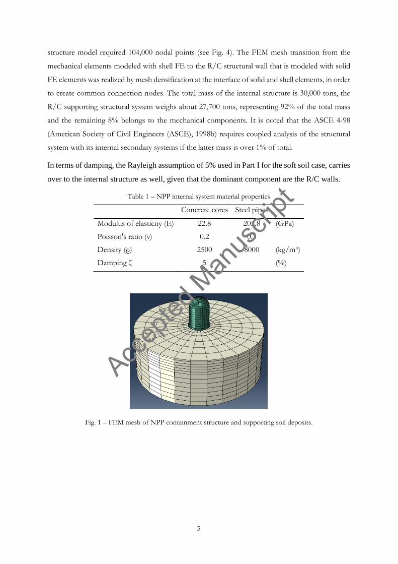
structure model required 104,000 nodal points (see Fig. 4). The FEM mesh transition from the
mechanical elements modeled with shell FE to the R/C structural wall that is modeled with solid
FE elements was realized by mesh densification at the interface of solid and shell elements, in order
to create common connection nodes. The total mass of the internal structure is 30,000 tons, the
R/C supporting structural system weighs about 27,700 tons, representing 92% of the total mass
and the remaining 8% belongs to the mechanical components. It is noted that the ASCE 4-98
(American Society of Civil Engineers (ASCE), 1998b) requires coupled analysis of the structural
system with its internal secondary systems if the latter mass is over 1% of total.
In terms of damping, the Rayleigh assumption of 5% used in Part I for the soft soil case, carries
over to the internal structure as well, given that the dominant component are the R/C walls.
Table 1 – NPP internal system material properties
Concrete cores Steel pipes
Modulus of elasticity (E) 22.8 205.8 (GPa)
Poisson's ratio (ν) 0.2 0.3
Density (ρ) 2500 8000 (kg/m³)
Damping ζ 5 (%)
Fig. 1 – FEM mesh of NPP containment structure and supporting soil deposits.
Accep
ted M
anus
cript

6
Fig. 2 – Isometric view of the wall support structure (left) and of the main mechanical elements (right).
Fig. 3 – FEM meshing of the wall support structure (left) and the main mechanical elements (right).
NPP ALTERNATIVE METHODS OF ANALYSIS
As the main goal of the numerical analysis was to make exploratory calculations for the seismically-
induced state of stress in the mechanical equipment, alternative approaches were adopted in order
to gradually establish confidence to the FEM model. Apparently, these dynamic stresses
numerically predicted for the case of sliding and rocking of the containment building are not
standalone; they must be combined with the other actions influencing the piping system such as,
internal pressure or constrained thermal expansion for the determination of the final nominal stress
according to ASME (American Society of Mechanical Engineers (ASME), 2010a). The purpose,
Accep
ted M
anus
cript
7
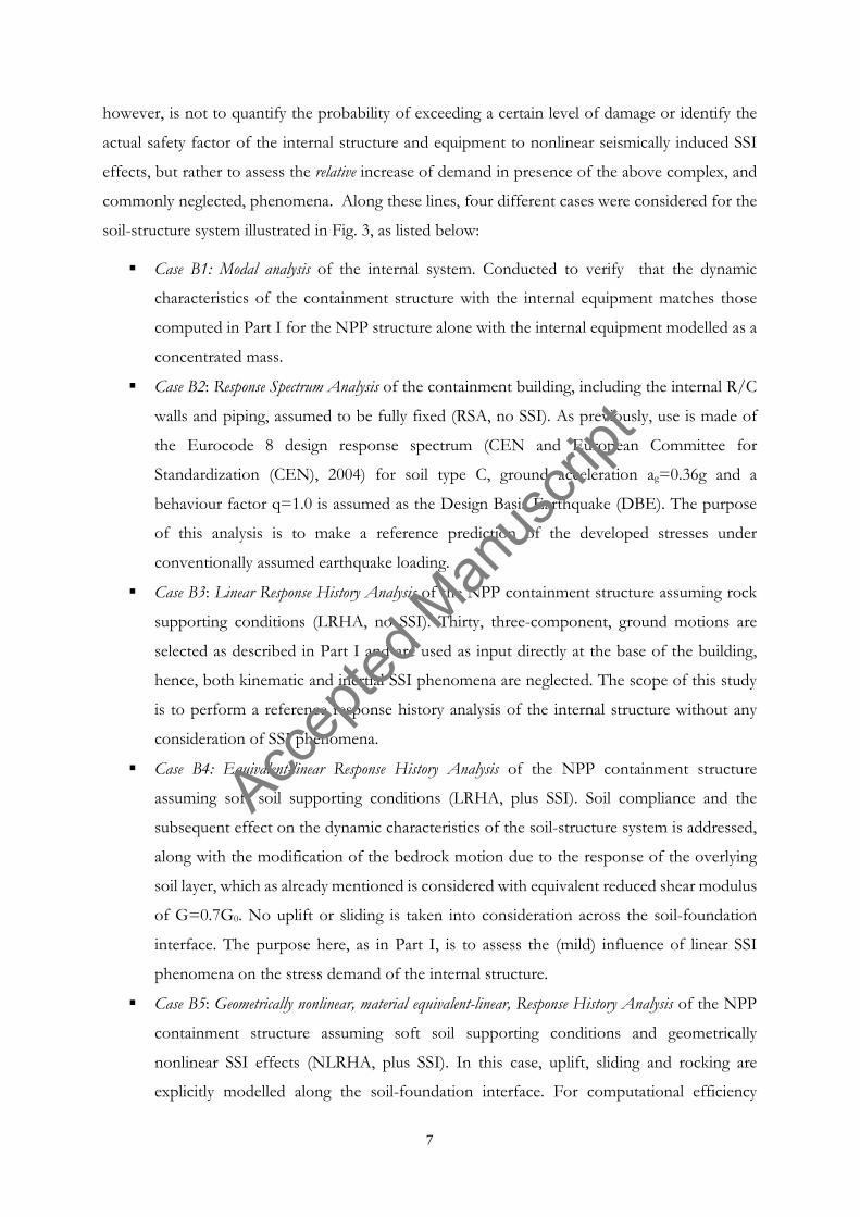
however, is not to quantify the probability of exceeding a certain level of damage or identify the
actual safety factor of the internal structure and equipment to nonlinear seismically induced SSI
effects, but rather to assess the relative increase of demand in presence of the above complex, and
commonly neglected, phenomena. Along these lines, four different cases were considered for the
soil-structure system illustrated in Fig. 3, as listed below:
Case B1: Modal analysis of the internal system. Conducted to verify that the dynamic
characteristics of the containment structure with the internal equipment matches those
computed in Part I for the NPP structure alone with the internal equipment modelled as a
concentrated mass.
Case B2: Response Spectrum Analysis of the containment building, including the internal R/C
walls and piping, assumed to be fully fixed (RSA, no SSI). As previously, use is made of
the Eurocode 8 design response spectrum (CEN and European Committee for
Standardization (CEN), 2004) for soil type C, ground acceleration ag=0.36g and a
behaviour factor q=1.0 is assumed as the Design Basis Earthquake (DBE). The purpose
of this analysis is to make a reference prediction of the developed stresses under
conventionally assumed earthquake loading.
Case B3: Linear Response History Analysis of the NPP containment structure assuming rock
supporting conditions (LRHA, no SSI). Thirty, three-component, ground motions are
selected as described in Part I and are used as input directly at the base of the building,
hence, both kinematic and inertial SSI phenomena are neglected. The scope of this study
is to perform a reference response history analysis of the internal structure without any
consideration of SSI phenomena.
Case B4: Equivalent-linear Response History Analysis of the NPP containment structure
assuming soft soil supporting conditions (LRHA, plus SSI). Soil compliance and the
subsequent effect on the dynamic characteristics of the soil-structure system is addressed,
along with the modification of the bedrock motion due to the response of the overlying
soil layer, which as already mentioned is considered with equivalent reduced shear modulus
of G=0.7G0. No uplift or sliding is taken into consideration across the soil-foundation
interface. The purpose here, as in Part I, is to assess the (mild) influence of linear SSI
phenomena on the stress demand of the internal structure.
Case B5: Geometrically nonlinear, material equivalent-linear, Response History Analysis of the NPP
containment structure assuming soft soil supporting conditions and geometrically
nonlinear SSI effects (NLRHA, plus SSI). In this case, uplift, sliding and rocking are
explicitly modelled along the soil-foundation interface. For computational efficiency
Accep
ted M
anus
cript
8
purposes, this is achieved by decoupling the containment building and its supporting soil
and applying the response history of Case A6 defined in Part I as the base excitation of the
building.
DYNAMIC ANALYSIS OF THE NPP INTERNAL SYSTEM
Case B2: Response Spectrum Analysis
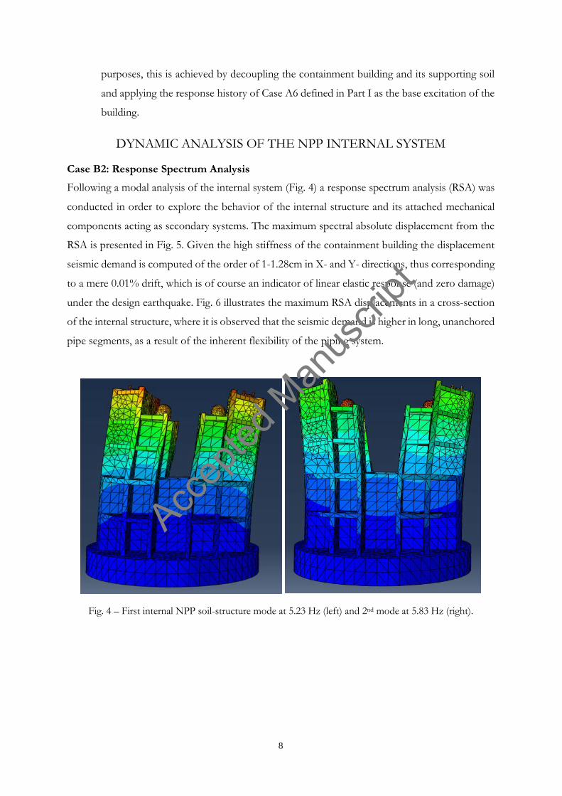
Following a modal analysis of the internal system (Fig. 4) a response spectrum analysis (RSA) was
conducted in order to explore the behavior of the internal structure and its attached mechanical
components acting as secondary systems. The maximum spectral absolute displacement from the
RSA is presented in Fig. 5. Given the high stiffness of the containment building the displacement
seismic demand is computed of the order of 1-1.28cm in X- and Y- directions, thus corresponding
to a mere 0.01% drift, which is of course an indicator of linear elastic response (and zero damage)
under the design earthquake. Fig. 6 illustrates the maximum RSA displacements in a cross-section
of the internal structure, where it is observed that the seismic demand is higher in long, unanchored
pipe segments, as a result of the inherent flexibility of the piping system.
Fig. 4 – First internal NPP soil-structure mode at 5.23 Hz (left) and 2nd mode at 5.83 Hz (right).
Accep
ted M
anus
cript

9
Fig. 5 – Maximum displacement for case B2: Excitation in the X-direction (left) and Y-direction (right)
Fig. 6 – Maximum dynamic displacement distribution in the NPP internal structure as computed from the response spectrum analysis (Case B2) in the X-direction (left). Piping system detail (right).
Accep
ted M
anus
cript

10
Fig. 7 – Maximum principal dynamic stress distribution for excitation along the X-direction in the NPP internal structure.
Fig. 8 – Tresca stress distribution in the piping system for excitation in the X-direction.
Accep
ted M
anus
cript

11
Fig. 9 – Tresca stress distribution in the piping system for excitation in the Y-direction.
As far as the principal dynamic stresses are concerned, Fig. 7 gives a general overview of their
distribution within the internal structure, whereas, Figs. 8 and 9 both present Tresca stress
distribution in the piping system for excitation in the X- and Y-direction, respectively (American
Society of Mechanical Engineers (ASME), 2010a; Case et al., 1999). It is observed that the
seismically-induced stress is accumulated in the elbows and in the various connections with other
mechanical components, while relatively small stress values register along the straight pipe sections.
For instance, in Fig. 9 it is shown that along the straight pipe segments, stress values are in order
of 0.5 to 1 MPa, as compared to values of 20-30 MPa that developed in the elbows.
Cases B3-B5: Linear and Nonlinear Response History Analyses, with and without SSI
All three Cases B3-B5 use the extracted 60 modes of the internal structure as the basis to conduct
modal response history integration. As previously mentioned, thirty recorded ground acceleration
time histories are used for each case. In the Newmark-beta time integration algorithm, the time
step used is 0.005s. The resulting maximum dynamic stress tensor from each time history record,
along with the calculated maximum stress from the RSA of Case B2, are presented in Tables 2-4
for ground motions of different frequency content (i.e., low, medium and high). It is observed
that there are significant differences in the maximum response as registered by the different analysis
approaches (i.e., with or without SSI and with or without soil-foundation contact effects). A first
observation in all three Tables (suites of motions with different frequency content) is that on
average, the RSA of the fixed-based system (Case B2) leads to higher seismic demand, compared
to the all Response History Analysis cases, despite the fact that the accelerograms were scaled so
that their mean spectrum matched that of the design target one.
Accep
ted M
anus
cript

12
It is also evident that stresses from Case B5, that even though stresses in the pipping system are
on average higher (in terms of their maxima) for excitation along the X direction, here is no critical
X or Y direction as the seismic demand can be higher or lower for different excitation records and
axis of excitation. Another interesting observation is that when geometrical nonlinearities in form
of uplift and sliding in the soil-foundation interface are taken into consideration, the developed
(average and maximum) stresses and generally 50-100% higher compared to Cases B3 and B4
neglecting this effect, with the exception of high frequency ground motions. This effectively
implies that the mechanical equipment of NPPs resting on soft soils and subjected to far-field,
long period earthquake ground motions (0.9<Tm<1.55sec) are susceptible to significantly
increased seismic demand particularly at the piping elbows that may well exceed the design value
by roughly 25-60% for the Y and X direction, respectively. Conclusions
The seismic response of the piping system in the NPP containment building that forms part of the
main cooling system of a typical nuclear reactor facility is studied in Part II of this work. To this
purpose, a fully 3D FEM analysis of the supporting soil, the internal structure and its mechanical
equipment is carried out. The analyses include both Response Spectrum Analysis with the Design
Basis Earthquake spectrum, as well as Response History Analyses from actual ground motion input
that is categorized in terms of the frequency content of the recorded motions as high, moderate
and low. Different analysis approaches of increasing complexity (and computational cost) are
carried out involving alternative considerations of soil compliance (i.e., structural fixity versus a 3D
FE representation of the soil system) and of geometrical nonlinearities (in terms of potential uplift
and sliding along the soil-foundation interface). From all these seismic scenarios, it is evident that
the assumptions made regarding the modeling of the above effects have a significant impact in the
seismic demand computed within the internal piping system. It is also shown that long period
pulses may result to either in uplift or sliding of the containment building if it rests on soft soil
formations. This, in turn, amplifies the stress demand in the pipe elbows by approximately 50-
100%. Overall, Response Spectrum Analysis is proven inadequate to capture complex material and
geometrically nonlinear SSI phenomena, as well as in predicting the distribution of maximum
stresses in the mechanical equipment.
Accep
ted M
anus
cript

13
Fig. 10 – Critical regions in the piping system as computed from the time history stress analysis.
Table 2 – Maximum stress (in MPa) recorded in the piping system from the time history analyses:
Low frequency excitations in both X- and Y- directions for all cases B2-B5
Tm 3 NL Case B2
Case B3
Case B4
Case B5
Case B2
Case B3
Case B4
Case B5
X Direction Y Direction ChiChi -
50,4 (RSA)
12,5 22,7 29,9
35,8 (RSA)
9,8 18,0 18,0 Coalinga R-S 12,1 23,6 42,2 10,9 19,2 34,4
Imp Val EMO S 12,9 19,0 20,3 9,8 15,7 17,6 Imp Val ECC R-S 14,0 24,4 56,6 12,8 19,2 38,7 Imp Val BRA - 19,5 20,4 16,8 14,5 14,0 14,5
Kobe R-S 11,2 33,8 56,7 9,5 30,0 37,8 Kocaeli R-S 12,9 29,6 79,5 11,7 26,0 43,1 Loma P R-S 10,5 37,5 51,0 9,0 32,0 37,7 North R-S 11,5 18,5 28,1 10,0 16,2 23,0 Smart R-S 11,2 28,9 49,4 6,9 25,7 32,4
AVERAGE 12,8 25,8 43,1 10,5 21,6 29,7 MAX 19,5 37,5 79,5 14,5 32,0 43,1
Table 1 – Maximum stress (in MPa) recorded in the piping system from the time history analyses: Medium frequency excitations in both X- and Y- directions for all cases B2-B5
Tm 2 NL Case B2
Case B3
Case B4
Case B5
Case B2
Case B3
Case B4
Case B5
X Direction Y Direction ChiChi HWA -
50,4 (RSA)
12,0 18,5 21,0
35,8 (RSA)
10,0 14,0 17,0 ChiChi TCU - 12,5 19,8 16,0 8,0 12,3 12,0
Coalinga S 16,7 30,8 30,0 10,0 22,0 24,0 Imp Vall - 21,0 24,0 20,0 14,0 18,0 16,0
Kobe - 13,0 21,7 13,0 9,2 12,5 11,4 Kocaeli - 19,5 28,5 16,0 10,0 16,0 13,7 Loma P S-R 15,4 30,0 41,1 10,7 21,5 30,0 North - 17,0 22,0 14,0 16,3 20,8 11,2 S Fern S-R 12,5 27,6 44,0 8,6 21,2 13,6
Whittier S-R 12,1 24,5 30,0 10,3 18,5 20,1
Accep
ted M
anus
cript
14
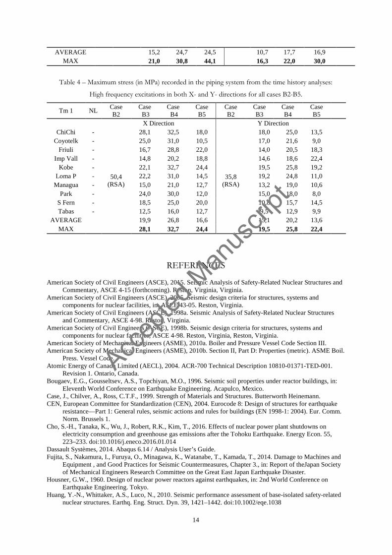
AVERAGE 15,2 24,7 24,5 10,7 17,7 16,9 MAX 21,0 30,8 44,1 16,3 22,0 30,0
Table 4 – Maximum stress (in MPa) recorded in the piping system from the time history analyses:
High frequency excitations in both X- and Y- directions for all cases B2-B5.
Tm 1 NL Case B2
Case B3
Case B4
Case B5
Case B2
Case B3
Case B4
Case B5
X Direction Y Direction ChiChi -
50,4 (RSA)
28,1 32,5 18,0
35,8 (RSA)
18,0 25,0 13,5 Coyotelk - 25,0 31,0 10,5 17,0 21,6 9,0
Friuli - 16,7 28,8 22,0 14,0 20,5 18,3 Imp Vall - 14,8 20,2 18,8 14,6 18,6 22,4
Kobe - 22,1 32,7 24,4 19,5 25,8 19,2 Loma P - 22,2 31,0 14,5 19,2 24,8 11,0
Managua - 15,0 21,0 12,7 13,2 19,0 10,6 Park - 24,0 30,0 12,0 15,0 18,0 8,0
S Fern - 18,5 25,0 20,0 10,8 15,7 14,5 Tabas - 12,5 16,0 12,7 9,5 12,9 9,9
AVERAGE 19,9 26,8 16,6 15,1 20,2 13,6 MAX 28,1 32,7 24,4 19,5 25,8 22,4
REFERENCES
American Society of Civil Engineers (ASCE), 2015. Seismic Analysis of Safety-Related Nuclear Structures and Commentary, ASCE 4-15 (forthcoming). Reston, Virginia, Virginia.
American Society of Civil Engineers (ASCE), 2005. Seismic design criteria for structures, systems and components for nuclear facilities, in: ASCE 43-05. Reston, Virginia.
American Society of Civil Engineers (ASCE), 1998a. Seismic Analysis of Safety-Related Nuclear Structures and Commentary, ASCE 4-98. Reston, Virginia.
American Society of Civil Engineers (ASCE), 1998b. Seismic design criteria for structures, systems and components for nuclear facilities, ASCE 4-98. Reston, Virginia, Reston, Virginia.
American Society of Mechanical Engineers (ASME), 2010a. Boiler and Pressure Vessel Code Section III. American Society of Mechanical Engineers (ASME), 2010b. Section II, Part D: Properties (metric). ASME Boil.
Press. Vessel Code. Atomic Energy of Canada Limited (AECL), 2004. ACR-700 Technical Description 10810-01371-TED-001.
Revision 1. Ontario, Canada. Bougaev, E.G., Gousseltsev, A.S., Topchiyan, M.O., 1996. Seismic soil properties under reactor buildings, in:
Eleventh World Conference on Earthquake Engineering. Acapulco, Mexico. Case, J., Chilver, A., Ross, C.T.F., 1999. Strength of Materials and Structures. Butterworth Heinemann. CEN, European Committee for Standardization (CEN), 2004. Eurocode 8: Design of structures for earthquake
resistance—Part 1: General rules, seismic actions and rules for buildings (EN 1998-1: 2004). Eur. Comm. Norm. Brussels 1.
Cho, S.-H., Tanaka, K., Wu, J., Robert, R.K., Kim, T., 2016. Effects of nuclear power plant shutdowns on electricity consumption and greenhouse gas emissions after the Tohoku Earthquake. Energy Econ. 55, 223–233. doi:10.1016/j.eneco.2016.01.014
Dassault Systèmes, 2014. Abaqus 6.14 / Analysis User’s Guide. Fujita, S., Nakamura, I., Furuya, O., Minagawa, K., Watanabe, T., Kamada, T., 2014. Damage to Machines and
Equipment , and Good Practices for Seismic Countermeasures, Chapter 3., in: Report of theJapan Society of Mechanical Engineers Research Committee on the Great East Japan Earthquake Disaster.
Housner, G.W., 1960. Design of nuclear power reactors against earthquakes, in: 2nd World Conference on Earthquake Engineering. Tokyo.
Huang, Y.-N., Whittaker, A.S., Luco, N., 2010. Seismic performance assessment of base-isolated safety-related nuclear structures. Earthq. Eng. Struct. Dyn. 39, 1421–1442. doi:10.1002/eqe.1038
Accep
ted M
anus
cript

15
Iijima, T., Abe, H., Fujita, T., 2004. Program Outline of Seismic Fragility Capacity Tests on Nuclear Power Plant Equipment, in: 12th International Conference on Nuclear Engineering, Volume 2 Arlington, Virginia, USA, April 25–29.
Kramer, S.L.S.L., 1996. Geotechnical earthquake engineering, First. ed, Prentice Hall. Upper Saddle River, New Jersey.
Lee, H., Ou, Y.C., Roh, H., Lee, J.S., 2014. Simplified model and seismic response of integrated nuclear containment system based on frequency adaptive lumped-mass stick modeling approach. KSCE J. Civ. Eng. doi:10.1007/s12205-014-1295-3
Nakamura, N., Tanaka, K., Tokuhira, H., Miura, J., 2006. Collaboration work for nuclear power building using 3D CAD information. Nucl. Eng. Des. 236, 368–374. doi:10.1016/j.nucengdes.2005.09.004
Nuclear Regulatory Commission (NRC), 2009. Regulatory Guide 1.100. Seismic qualification of electrical and active mechanical equipment and functional qualification of active mechanical equipment for nuclear power plants. Office of Nuclear Regulatory Research, United States.
Takada, T, 2012. On Seismic Design Qualification of NPPs After Fukushima Event in Japan. 15th World Conf. Earthq. Eng.
Accep
ted M
anus
cript