sfc series clutch coupling - warner electric parts1.750 max. dia. all dimensions are nominal unless...
TRANSCRIPT

90 Warner Electric 800-234-3369 ......P-1264-WE 3/14
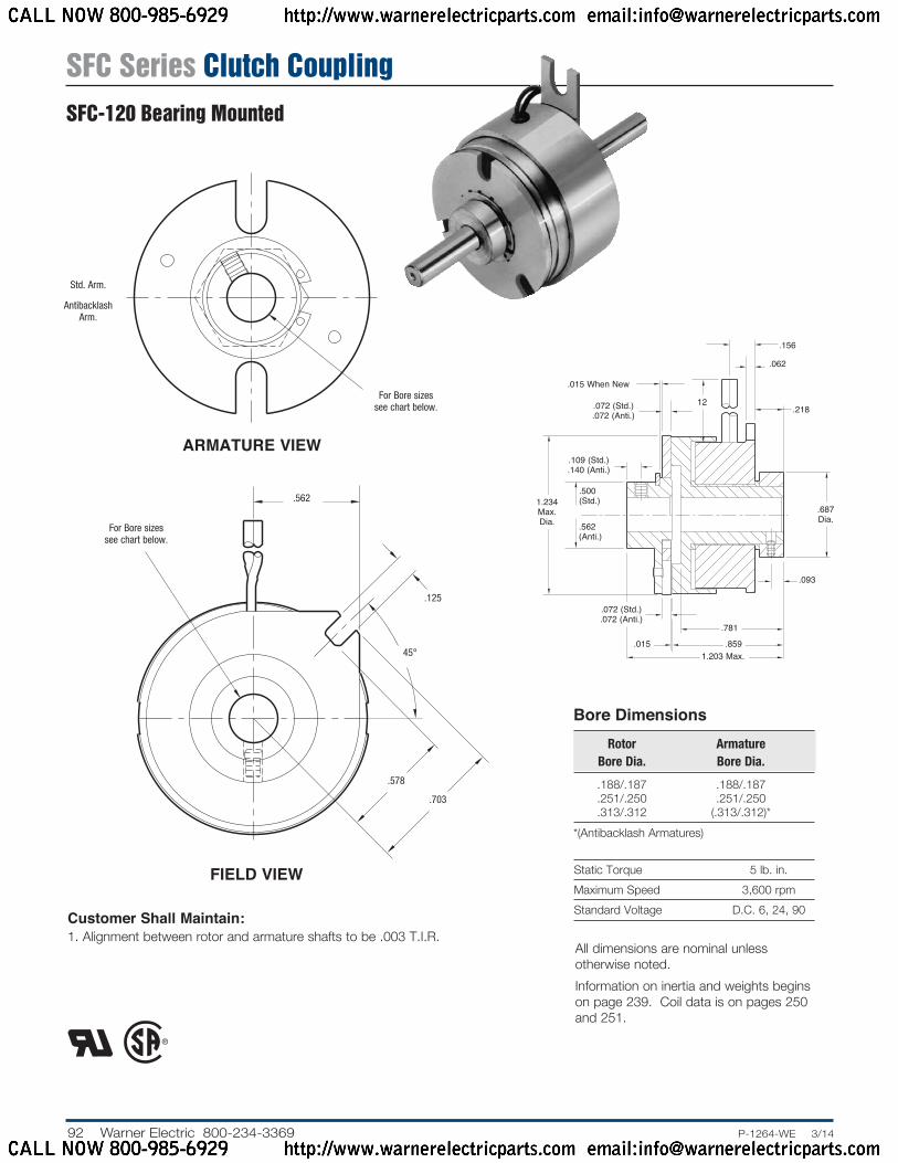
Static Torque 5 lb. in.Maximum Speed 3,600 rpmStandard Voltage D.C. 6, 24, 90
Customer Shall Maintain:1. Squareness of field mounting face with rotor
shaft within .003 T.I.R. measured at pilot diameter2. Concentricity of field mounting pilot diameter
with rotor mounting shaft within .003 T.I.R.3. Rotor and armature shafts in line within .003 T.I.R.
Bore Di men sions Rotor Armature Bore Dia. Bore Dia.
.188/.187 .188/.187 .251/.250 .251/.250 .313/.312 (.313/.312)**(Antibacklash Armatures)
ARMATURE VIEW
FIELD VIEW
Std. Arm.
Antibacklash Arm.
For Bore sizes see chart below.
.130/.123 dia. (4) holes equally spaced on 1.312 dia. Mounting holes are within .006 of true position relative to pilot diameter.
For Bore sizes see chart below.
45°
1.499/1.497 Pi lot Dia.
1.140 Max. Sq.
12 Min..062
.063/.062 dia. (2) holes
equally spaced.
.109
.156
.019
.000
.187 Max.
.500
.109 (Std.) .140 (Anti.)
.072 (Std.).072 (Anti.)
.015
.015 When New
Std. Arm
.562
.968 (Std.).968 (Anti.)
.625
.546.343
.072 (Std.).072
(Anti.)
Antibacklash Arm.
1.234 Max. Dia.
#4-40 UNC-3A
All dimensions are nominal unless otherwise noted.Information on inertia and weights begins on page 239. Coil data is on pages 250 and 251.
SFC Series Clutch CouplingSFC-120 Flange Mounted
CALL NOW 800-985-6929 http://www.warnerelectricparts.com email:[email protected]
CALL NOW 800-985-6929 http://www.warnerelectricparts.com email:[email protected]

91.P-1264-WE 3/14..... Warner Electric 800-234-3369
Drawing I-25503
1B
1A-1
1A-2
2
4
1A
3
How to Order:1. Specify Type of Armature Desired.2. Specify Bore Size for Item 1A-1 or 1B and
Item 2.3. Specify Voltage for Item 4.4. See Controls Section.Example:SFC-120 Clutch per I-25503 - 90 Volt Standard Armature 1/4” Armature Hub Bore 1/4” Rotor BoreThese units meet standards set forth in UL508 and are listed under guide card #NMTR2, file #59164.These units are CSA certified under file #LR11543.
Item Description Part Number Qty.
1A Armature and Hub1A-1 Armature Hub 1 3/16” Bore 5622-541-009 1/4” Bore 5622-541-0081A-2 Armature 110-0110 11B Antibacklash Armature 1 3/16” Bore 5622-111-004 1/4” Bore 5622-111-002 5/16” Bore 5622-111-0032 Rotor 1 3/16” Bore 5602-751-004 1/4” Bore 5602-751-002 5/16” Bore 5602-751-0033 Mounting Accessory 5101-101-001 14 Field 1 6 Volt 5602-451-003 24 Volt 5602-451-005 90 Volt 5602-451-007
Refer to Service Manual P-200.
SFC Series Clutch CouplingSFC-120 Flange Mounted
CALL NOW 800-985-6929 http://www.warnerelectricparts.com email:[email protected]
CALL NOW 800-985-6929 http://www.warnerelectricparts.com email:[email protected]
92 Warner Electric 800-234-3369 ......P-1264-WE 3/14
Static Torque 5 lb. in.Maximum Speed 3,600 rpmStandard Voltage D.C. 6, 24, 90
Bore Di men sions Rotor Armature Bore Dia. Bore Dia.
.188/.187 .188/.187 .251/.250 .251/.250 .313/.312 (.313/.312)**(Antibacklash Armatures)
Customer Shall Maintain:1. Alignment between rotor and armature shafts to be .003 T.I.R.
FIELD VIEW
ARMATURE VIEW
.156
.015 When New
.072 (Std.).072 (Anti.)
.062
12
.109 (Std.).140 (Anti.)
.218
.500 (Std.)
.093
.562 (Anti.)
.072 (Std.).072 (Anti.)
.015
.687 Dia.
.781
.8591.203 Max.
1.234 Max. Dia.
For Bore sizes see chart below.
.125
.578
.703
45°
.562
For Bore sizes see chart below.
Std. Arm.
Antibacklash Arm.
All dimensions are nominal unless otherwise noted.Information on inertia and weights begins on page 239. Coil data is on pages 250 and 251.
SFC Series Clutch CouplingSFC-120 Bearing Mounted
CALL NOW 800-985-6929 http://www.warnerelectricparts.com email:[email protected]
CALL NOW 800-985-6929 http://www.warnerelectricparts.com email:[email protected]
93.P-1264-WE 3/14..... Warner Electric 800-234-3369
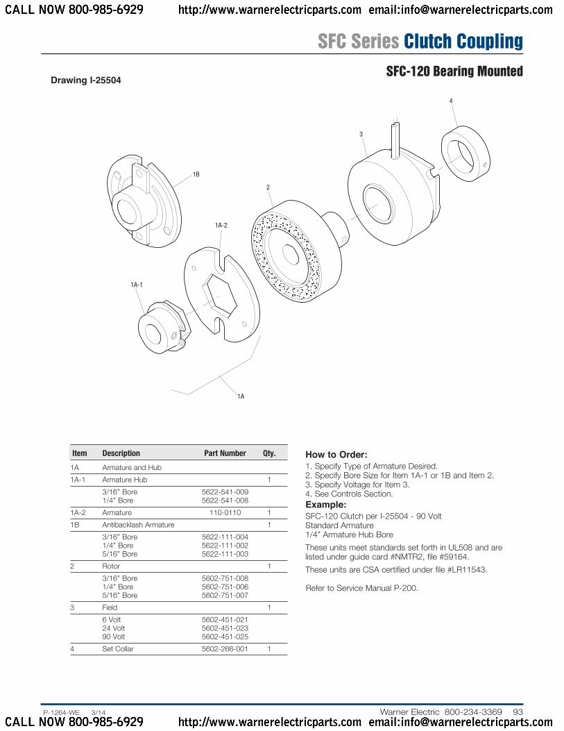
Drawing I-25504
1B
1A-1
2
1A-2
1A
3
4
How to Order:1. Specify Type of Armature Desired.2. Specify Bore Size for Item 1A-1 or 1B and Item 2.3. Specify Voltage for Item 3.4. See Controls Section.Example:SFC-120 Clutch per I-25504 - 90 Volt Standard Armature 1/4” Armature Hub BoreThese units meet standards set forth in UL508 and are listed under guide card #NMTR2, file #59164.These units are CSA certified under file #LR11543.
Item Description Part Number Qty.
1A Armature and Hub1A-1 Armature Hub 1 3/16” Bore 5622-541-009 1/4” Bore 5622-541-0081A-2 Armature 110-0110 11B Antibacklash Armature 1 3/16” Bore 5622-111-004 1/4” Bore 5622-111-002 5/16” Bore 5622-111-0032 Rotor 1 3/16” Bore 5602-751-008 1/4” Bore 5602-751-006 5/16” Bore 5602-751-0073 Field 1 6 Volt 5602-451-021 24 Volt 5602-451-023 90 Volt 5602-451-0254 Set Collar 5602-266-001 1
Refer to Service Manual P-200.
SFC Series Clutch CouplingSFC-120 Bearing Mounted
CALL NOW 800-985-6929 http://www.warnerelectricparts.com email:[email protected]
CALL NOW 800-985-6929 http://www.warnerelectricparts.com email:[email protected]
94 Warner Electric 800-234-3369 ......P-1264-WE 3/14
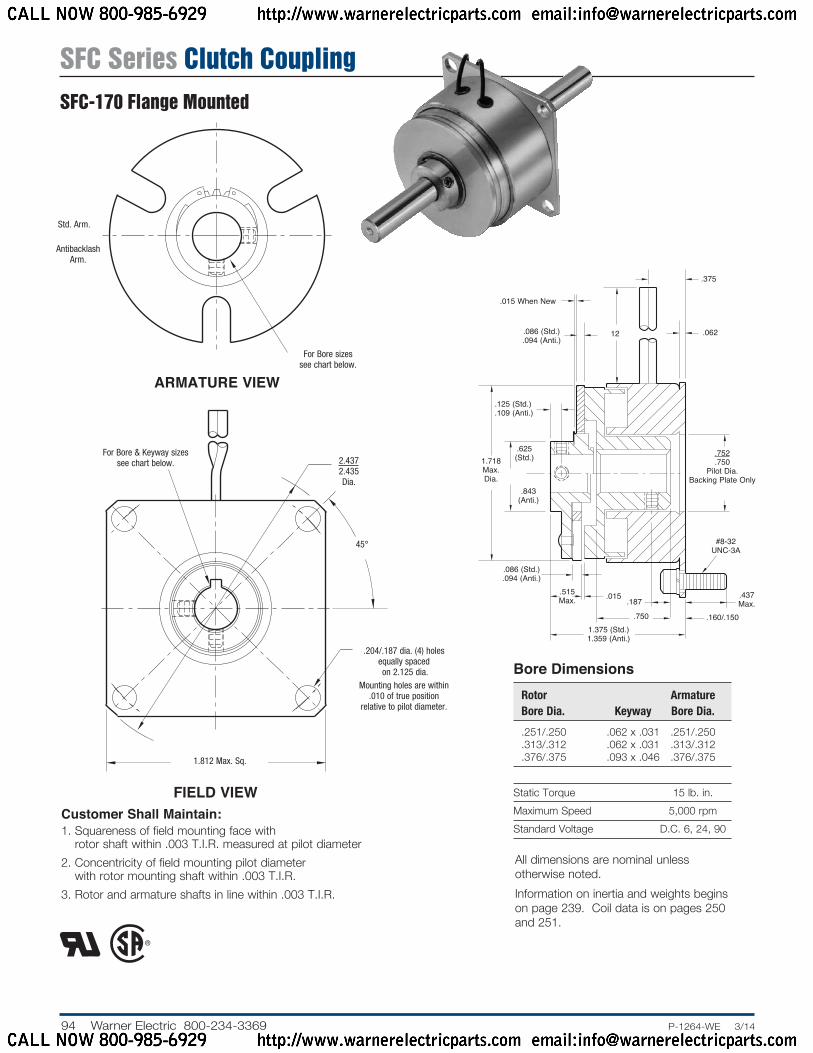
Static Torque 15 lb. in.Maximum Speed 5,000 rpmStandard Voltage D.C. 6, 24, 90
Bore Di men sions Rotor Armature Bore Dia. Keyway Bore Dia.
.251/.250 .062 x .031 .251/.250 .313/.312 .062 x .031 .313/.312 .376/.375 .093 x .046 .376/.375
Customer Shall Maintain:1. Squareness of field mounting face with
rotor shaft within .003 T.I.R. measured at pilot diameter2. Concentricity of field mounting pilot diameter
with rotor mounting shaft within .003 T.I.R.3. Rotor and armature shafts in line within .003 T.I.R.
ARMATURE VIEW
FIELD VIEW
.625 (Std.)
.125 (Std.)
.109 (Anti.)
.015 When New
.086 (Std.).094 (Anti.)
.015.515 Max.
.160/.150
.437 Max..187
#8-32 UNC-3A
.375
.06212
.752
.750Pi lot Dia.
Backing Plate Only.843
(Anti.)
.086 (Std.).094 (Anti.)
1.375 (Std.)1.359 (Anti.)
.750
1.718 Max. Dia.
Antibacklash Arm.
Std. Arm.
For Bore sizes see chart below.
45°
.204/.187 dia. (4) holes equally spaced on 2.125 dia.
Mounting holes are within .010 of true position
relative to pilot diameter.
For Bore & Keyway sizes see chart below. 2.437
2.435 Dia.
1.812 Max. Sq.
All dimensions are nominal unless otherwise noted.Information on inertia and weights begins on page 239. Coil data is on pages 250 and 251.
SFC Series Clutch CouplingSFC-170 Flange Mounted
CALL NOW 800-985-6929 http://www.warnerelectricparts.com email:[email protected]
CALL NOW 800-985-6929 http://www.warnerelectricparts.com email:[email protected]

95.P-1264-WE 3/14..... Warner Electric 800-234-3369
1A-1
1A
1A-2
1A-3
1B
3
2
4
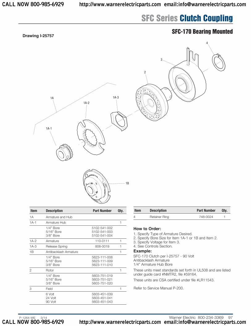
Drawing I-25756
How to Order:1. Specify Type of Armature Desired.2. Specify Bore Size for Item 1A-1 or 1B and Item 2.3. Specify Voltage for Item 4.4. See Controls Section.Example:SFC-170 Clutch per I-25756 - 90 Volt Antibacklash Armature 1/4” Armature Hub Bore 1/4” Rotor BoreThese units meet standards set forth in UL508 and are listed under guide card #NMTR2, file #59164. These units are CSA certified under file #LR11543.
Item Description Part Number Qty.
1A Armature and Hub1A-1 Armature Hub 1 1/4” Bore 5102-541-002 5/16” Bore 5102-541-003 3/8” Bore 5102-541-0041A-2 Armature 110-0111 11A-3 Release Spring 808-0019 11B Antibacklash Armature 1 1/4” Bore 5623-111-008 5/16” Bore 5623-111-009 3/8” Bore 5623-111-0102 Rotor 1 1/4” Bore 5603-751-028 5/16” Bore 5603-751-029 3/8” Bore 5603-751-0303 Mounting Accessory 5102-101-001 14 Field 1 6 Volt 5603-451-047 24 Volt 5603-451-049 90 Volt 5603-451-051
Refer to Service Manual P-200.
SFC Series Clutch CouplingSFC-170 Flange Mounted
CALL NOW 800-985-6929 http://www.warnerelectricparts.com email:[email protected]
CALL NOW 800-985-6929 http://www.warnerelectricparts.com email:[email protected]
96 Warner Electric 800-234-3369 ......P-1264-WE 3/14
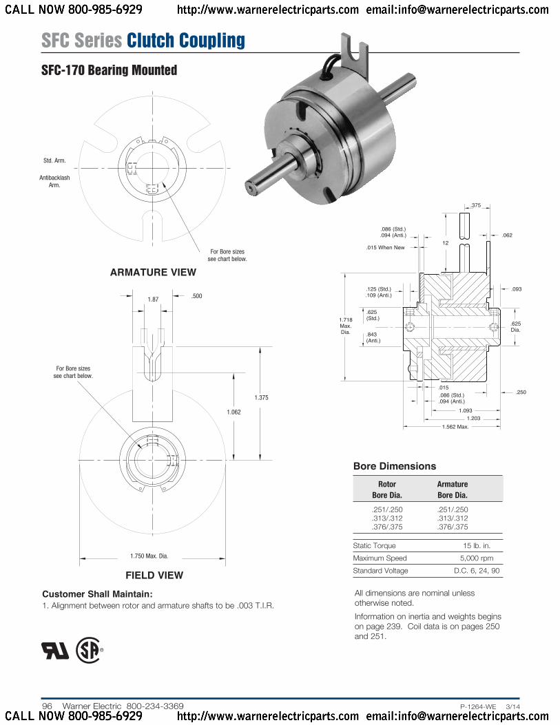
Static Torque 15 lb. in.Maximum Speed 5,000 rpmStandard Voltage D.C. 6, 24, 90
Customer Shall Maintain:1. Alignment between rotor and armature shafts to be .003 T.I.R.
Bore Di men sions Rotor Armature Bore Dia. Bore Dia.
.251/.250 .251/.250 .313/.312 .313/.312 .376/.375 .376/.375
ARMATURE VIEW
FIELD VIEW
.375
.015 When New
.06212
.125 (Std.).109 (Anti.)
.093
.625 (Std.)
.250
.843 (Anti.)
.015
.625 Dia.
1.718 Max. Dia.
.086 (Std.).094 (Anti.)
.086 (Std.).094 (Anti.)
1.562 Max.1.203
1.093
For Bore sizes see chart below.
Antibacklash Arm.
Std. Arm.
For Bore sizes see chart below.
1.87 .500
1.062
1.375
1.750 Max. Dia.
All dimensions are nominal unless otherwise noted.Information on inertia and weights begins on page 239. Coil data is on pages 250 and 251.
SFC Series Clutch CouplingSFC-170 Bearing Mounted
CALL NOW 800-985-6929 http://www.warnerelectricparts.com email:[email protected]
CALL NOW 800-985-6929 http://www.warnerelectricparts.com email:[email protected]
97.P-1264-WE 3/14..... Warner Electric 800-234-3369
Drawing I-25757
Item Description Part Number Qty.
1A Armature and Hub1A-1 Armature Hub 1 1/4” Bore 5102-541-002 5/16” Bore 5102-541-003 3/8” Bore 5102-541-0041A-2 Armature 110-0111 11A-3 Release Spring 808-0019 11B Antibacklash Armature 1 1/4” Bore 5623-111-008 5/16” Bore 5623-111-009 3/8” Bore 5623-111-0102 Rotor 1 1/4” Bore 5603-751-019 5/16” Bore 5603-751-021 3/8” Bore 5603-751-0203 Field 1 6 Volt 5603-451-039 24 Volt 5603-451-041 90 Volt 5603-451-043
How to Order:1. Specify Type of Armature Desired.2. Specify Bore Size for Item 1A-1 or 1B and Item 2.3. Specify Voltage for Item 3.4. See Controls Section.Example:SFC-170 Clutch per I-25757 - 90 Volt Antibacklash Armature 1/4” Armature Hub BoreThese units meet standards set forth in UL508 and are listed under guide card #NMTR2, file #59164.These units are CSA certified under file #LR11543.
Item Description Part Number Qty.
4 Retainer Ring 748-0024 1
1A
1A-1
1A-2
1B
1A-3
2
3
4
Refer to Service Manual P-200.
SFC Series Clutch CouplingSFC-170 Bearing Mounted
CALL NOW 800-985-6929 http://www.warnerelectricparts.com email:[email protected]
CALL NOW 800-985-6929 http://www.warnerelectricparts.com email:[email protected]

98 Warner Electric 800-234-3369 ......P-1264-WE 3/14
Static Torque 70 lb. in.Maximum Speed 7,500 rpmStandard Voltage D.C. 6, 24, 90
Customer Shall Maintain:1. Squareness of field mounting face with rotor shaft within .003
T.I.R. measured at pilot di am e ter.2. Concentricity of field mounting pilot diameter with rotor
mounting shaft within .003 T.I.R.3. Rotor and armature shafts in line within .003 T.I.R.
Bore and Keyway Di men sions Armature Keyway Rotor Key way Bore Dia. Bore Dia.
.376/.375 .093 x .046 *.438/.437 .376/.375 .093 x .046 .501/.500 .125 x .062 *.438/.437 .125x .062 *.563/.562 .501/.500 .626/.625 *.688/.687 .187 x .093 .751/.750 * Available on special order only.
ARMATURE VIEW
FIELD VIEW
1.187 (Std.)
.171
.171 (Std.).562 (Anti.)
.437 Max.
8-32 UNC-3A
.546 Max.
.171
.062.343 Max.
1.0631.061
Pilot Dia.
.015
.380/.370
Backing Plate Only
1.390 (Anti.)
.015 When New
2.625 Max. Dia.
.687
1.125.468
1.968 (Std.)1.984 (Anti.)
.750
1.250
Std. Arm.
Antibacklash Arm.
For Bore & Keyway sizes see chart below.
3.500/3.498 Pilot Dia.
.437 Max.
.437 Max.
12°
24°
45°
For Bore & Key way sizes see chart
be low.
.204/.187 dia. (4) holes equally spaced on 3.125 dia. Mounting holes are within .010 of true po si tion relative
to pilot diameter.
2.625 Sq.
All dimensions are nominal unless otherwise noted.Information on inertia and weights begins on page 239. Coil data is on pages 250 and 251.
SFC Series Clutch CouplingSFC-250 Flange Mounted
CALL NOW 800-985-6929 http://www.warnerelectricparts.com email:[email protected]
CALL NOW 800-985-6929 http://www.warnerelectricparts.com email:[email protected]
99.P-1264-WE 3/14..... Warner Electric 800-234-3369
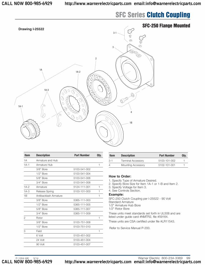
Drawing I-25522
How to Order:1. Specify Type of Armature Desired.2. Specify Bore Size for Item 1A-1 or 1-B and Item 2.3. Specify Voltage for Item 3.4. See Controls Section.Example:SFC-250 Clutch Coupling per I-25522 - 90 Volt Standard Armature 1/2” Armature Hub Bore 1/2” Rotor BoreThese units meet standards set forth in UL508 and are listed under guide card #NMTR2, file #59164.These units are CSA certified under file #LR11543.
1A-1
1A-3
1A1A-2
2
4
3
3-1
1B
Item Description Part Number Qty.
1A Armature and Hub1A-1 Armature Hub 1 3/8” Bore 5103-541-002 1/2” Bore 5103-541-004 5/8” Bore 5103-541-006 3/4” Bore 5103-541-0081A-2 Armature 5124-111-001 11A-3 Release Spring 5103-101-003 11B Antibacklash Armature 1 3/8” Bore 5365-111-003 1/2” Bore 5365-111-005 5/8” Bore 5365-111-007 3/4” Bore 5365-111-0092 Rotor 1 3/8” Bore 5103-751-008 1/2” Bore 5103-751-0103 Field 1 6 Volt 5103-451-002 24 Volt 5103-451-004 90 Volt 5103-451-007
Item Description Part Number Qty.
3-1 Terminal Accessory 5103-101-002 14 Mounting Accessory 5102-101-001 1
Refer to Service Manual P-200.
SFC Series Clutch CouplingSFC-250 Flange Mounted
CALL NOW 800-985-6929 http://www.warnerelectricparts.com email:[email protected]
CALL NOW 800-985-6929 http://www.warnerelectricparts.com email:[email protected]

100 Warner Electric 800-234-3369 ......P-1264-WE 3/14
Static Torque 70 lb. in.Maximum Speed 7,500 rpmStandard Voltage D.C. 6, 24, 90
Bore and Keyway Di men sions Armature Keyway Rotor Key way Bore Dia. Bore Dia.
.375/.376 .093 x .046 .376/.375 .093 x .046 *.438/.437 .501/.500 .125 x .062 *.438/.437 .125 x .062 *.563/.562 .501/.500 .626/.625 *.688/.687 .187 x .093 .751/.750 * Available on special order only.
Customer Shall Maintain:1. Armature shaft to be concentric with rotor shaft
within .003 T.I.R.
ARMATURE VIEW
FIELD VIEW
1.187 (Std.)
.687 (Std.)
.687 (Std.).718
(Anti.)
.171
.062
.171 (Std.).187 (Anti.) .015 (Std.)
.015 (Anti.)
.343 Max.
.015 (Std.).015 (Anti.)when new .468
.171 + .062 -0
1.390 (Anti.)
.718 (Anti.)
2.625 Max. Dia.
1.437
1.125
.609 Dia.
1.312
2.156 (Std.)2.171 (Anti.)
Antibacklash Arm.
Std. Arm.
For Bore & Keyway sizes see chart below.
1.750 Max.
.187 Dia.
.437Max.
.500 12°
24°45°
For Bore & Key way sizes see chart be low.
.937
.187 1.562 Rad.
All dimensions are nominal unless otherwise noted.Information on inertia and weights begins on page 239. Coil data is on pages 250 and 251.
SFC Series Clutch CouplingSFC-250 Bearing Mounted
CALL NOW 800-985-6929 http://www.warnerelectricparts.com email:[email protected]
CALL NOW 800-985-6929 http://www.warnerelectricparts.com email:[email protected]
101.P-1264-WE 3/14..... Warner Electric 800-234-3369
1B
1A-1
1A
1A-3
1A-2
2-1 2-2
2-3
2(Shipped Assembled)
2-2
2-4
2-5
2-4-1
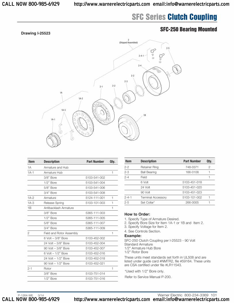
Drawing I-25523
How to Order:1. Specify Type of Armature Desired.2. Specify Bore Size for Item 1A-1 or 1B and Item 2.3. Specify Voltage for Item 2.4. See Controls Section.Example:SFC-250 Clutch Coupling per I-25523 - 90 Volt Standard Armature 1/2” Armature Hub Bore 1/2” Rotor BoreThese units meet standards set forth in UL508 and are listed under guide card #NMTR2, file #59164. These units are CSA certified under file #LR11543.
Item Description Part Number Qty.
1A Armature and Hub1A-1 Armature Hub 1 3/8” Bore 5103-541-002 1/2” Bore 5103-541-004 5/8” Bore 5103-541-006 3/4” Bore 5103-541-0081A-2 Armature 5124-111-001 11A-3 Release Spring 5103-101-003 11B Antibacklash Armature 1 3/8” Bore 5365-111-003 1/2” Bore 5365-111-005 5/8” Bore 5365-111-007 3/4” Bore 5365-111-0092 Field and Rotor Assembly 1 6 Volt – 3/8” Bore 5103-452-002 24 Volt – 3/8” Bore 5103-452-004 90 Volt – 3/8” Bore 5103-452-007 6 Volt – 1/2” Bore 5103-452-016 24 Volt – 1/2” Bore 5103-452-018 90 Volt – 1/2” Bore 5103-452-0212-1 Rotor 1 3/8” Bore 5103-751-014 1/2” Bore 5103-751-016
Item Description Part Num ber Qty.
2-2 Retainer Ring 748-0371 22-3 Ball Bearing 166-0108 12-4 Field 1 6 Volt 5103-451-018 24 Volt 5103-451-020 90 Volt 5103-451-0232-4-1 Terminal Accessory 5103-101-002 12-5 Set Collar* 266-0005 1
*Used with 1/2” Bore only.Refer to Service Manual P-200.
SFC Series Clutch CouplingSFC-250 Bearing Mounted
CALL NOW 800-985-6929 http://www.warnerelectricparts.com email:[email protected]
CALL NOW 800-985-6929 http://www.warnerelectricparts.com email:[email protected]

102 Warner Electric 800-234-3369 ......P-1264-WE 3/14
Static Torque 270 lb. in.Maximum Speed 4,500 rpmStandard Voltage D.C. 6, 24, 90
Bore and Keyway Di men sions Armature Keyway Rotor Key way Bore Dia. Bore Dia.
.501/.500 .125 x .062 .501/.500 .125 x.062 *.563/.562 .626/.625 .626/.625 *.688/.687 .187 x .093 .751/.750 .187 x .093 .751/.750 .876/.875 .876/.875 1.001/1.000*Available on special order only
ARMATURE VIEW
* Mounting holes are within .010 of true position relative to pilot diameter.
FIELD VIEW
1.8751.873
Pilot Dia.
1/4-20 UNC-3A
1.250 (Std.)
.328
.015
.671
3.562
.609 Max.
.328 Max.
.015 When New
.187 (Std.).218 (Anti.)
.250.093
1.640 (Anti.)
1.546
.937
.8754.234 Max. Dia.
.187 (Std.).218 (Anti.)
.828 1.312
1.500
1.502.328/2.359
.192/.182
1.125
Antibacklash Arm.
Std. Arm.
For Bore & Keyway sizes see chart below.
For Bore & Key way sizes see chart below.
Removable plug in ends for 1/2” conduit.
45°
.296/.280 dia. (4) holes equally spaced on 5.000 dia.*
4.250 Sq.
4.687
3.750
5.6265.623
Pilot Dia.
Customer Shall Maintain:1. Squareness of field mounting face with rotor shaft within .003
T.I.R. measured at pilot di am e ter.2. Concentricity of field mounting pilot diameter with rotor
mounting shaft within .003 T.I.R.3. Rotor and armature shafts in line within .003 T.I.R.
All dimensions are nominal unless otherwise noted.Information on inertia and weights begins on page 239. Coil data is on pages 250 and 251.
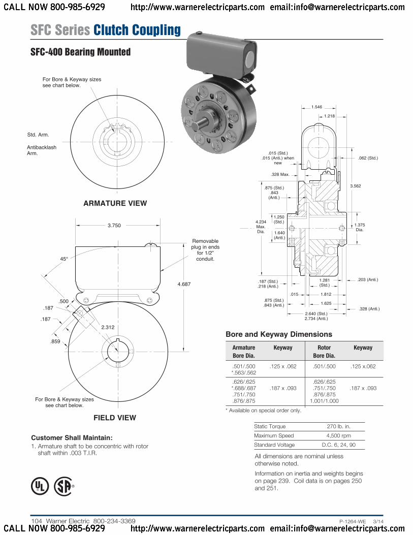
SFC Series Clutch CouplingSFC-400 Flange Mounted
CALL NOW 800-985-6929 http://www.warnerelectricparts.com email:[email protected]
CALL NOW 800-985-6929 http://www.warnerelectricparts.com email:[email protected]

103.P-1264-WE 3/14..... Warner Electric 800-234-3369
1A-1
1A-3
1A1A-2
2
3
5
3-1
4
1B
Drawing I-25697
How to Order:1. Specify Type of Armature Desired.2. Specify Bore Size for Item 1A-1 or 1B and Item 2.3. Specify Voltage for Item 3.4. See Controls Section.Example:SFC-400 Clutch Coupling per I-25697 - 90 Volt 3/4” Armature Hub Bore 3/4” Rotor BoreThese units, when used in conjunction with the correct Warner Electric conduit box, meet standards set forth in UL508 and are listed under guide card #NMTR2, file #59164.These units are CSA certified under file #LR11543.
Refer to Service Manual P-200.
Item Description Part Number Qty.
1A Armature and Hub1A-1 Armature Hub 1 1/2” Bore 5104-541-002 5/8” Bore 5104-541-004 3/4” Bore 5104-541-006 7/8” Bore 5104-541-0071A-2 Armature 5125-111-001 11A-3 Release Spring 5104-101-003 11B Antibacklash Armature 1 1/2” Bore 5367-111-003 5/8” Bore 5367-111-005 3/4” Bore 5367-111-007 7/8” Bore 5367-111-0082 Rotor 1 1/2” Bore 5104-751-033 5/8” Bore 5104-751-034 3/4” Bore 5104-751-035 7/8” Bore 5104-751-036 1” Bore 5104-751-0373 Field 1 6 Volt 5104-451-032 24 Volt 5104-451-033 90 Volt 5104-451-034
Item Description Part Number Qty.
3-1 Terminal Accessory 5103-101-002 14 Conduit Box 5200-101-010 15 Mounting Accessory 5104-101-002 1
SFC Series Clutch CouplingSFC-400 Flange Mounted
CALL NOW 800-985-6929 http://www.warnerelectricparts.com email:[email protected]
CALL NOW 800-985-6929 http://www.warnerelectricparts.com email:[email protected]
104 Warner Electric 800-234-3369 ......P-1264-WE 3/14
Static Torque 270 lb. in.Maximum Speed 4,500 rpmStandard Voltage D.C. 6, 24, 90
ARMATURE VIEW
Bore and Keyway Di men sions Armature Keyway Rotor Key way Bore Dia. Bore Dia.
.501/.500 .125 x .062 .501/.500 .125 x.062 *.563/.562 .626/.625 .626/.625 *.688/.687 .187 x .093 .751/.750 .187 x .093 .751/.750 .876/.875 .876/.875 1.001/1.000* Available on special order only.
Customer Shall Maintain:1. Armature shaft to be concentric with rotor
shaft within .003 T.I.R.
FIELD VIEW
Antibacklash Arm.
Std. Arm.
For Bore & Keyway sizes see chart below.
For Bore & Keyway sizes see chart below.
Re mov able plug in ends
for 1/2” conduit.
4.687
45°
.500
.859
2.312.187
.187
3.7501.250 (Std.)
.187 (Std.).218 (Anti.)
.015 (Std.).015 (Anti.) when
new
.015
.328 Max.
.328 (Anti.)
.203 (Anti.)
.062 (Std.)
.875 (Std.).843 (Anti.)
.875 (Std.).843
(Anti.)
3.562
1.640 (Anti.)
4.234 Max. Dia.
1.546
1.218
1.375 Dia.
1.281 (Std.)
1.812
1.625
2.640 (Std.)2.734 (Anti.)
All dimensions are nominal unless otherwise noted.Information on inertia and weights begins on page 239. Coil data is on pages 250 and 251.
SFC Series Clutch CouplingSFC-400 Bearing Mounted
CALL NOW 800-985-6929 http://www.warnerelectricparts.com email:[email protected]
CALL NOW 800-985-6929 http://www.warnerelectricparts.com email:[email protected]

105.P-1264-WE 3/14..... Warner Electric 800-234-3369
1B
1A-1
1A-3
1A-2
2-1
1-A
2(Shipped Assembled)
2-3
2-4
2-4-12-2
3
Drawing I-25698
How to Order:1. Specify Type of Armature Desired.2. Specify Bore Size for Item 1A-1 or 1-B and Item 2.3. Specify Voltage for Item 2.4. See Controls Section.Example:SFC-400 Clutch Coupling per I-25698 - 90 Volt Antibacklash Armature 3/4” Armature Hub Bore 3/4” Rotor BoreThese units meet standards set forth in UL508 and are listed under guide card #NMTR2, file #59164. These units are CSA certified under file #LR11543.
Item Description Part Number Qty.
1A Armature and Hub1A-1 Armature Hub 1 1/2” Bore 5104-541-002 5/8” Bore 5104-541-004 3/4” Bore 5104-541-006 7/8” Bore 5104-541-0071A-2 Armature 5125-111-001 11A-3 Release Spring 5104-101-003 11B Antibacklash Armature 1 1/2” Bore 5367-111-003 5/8” Bore 5367-111-005 3/4” Bore 5367-111-007 7/8” Bore 5367-111-0082 Field and Rotor Assembly 1 6 Volt – 1/2” Bore 5104-452-052 24 Volt – 1/2” Bore 5104-452-053 90 Volt – 1/2” Bore 5104-452-054 6 Volt – 5/8” Bore 5104-452-055 24 Volt – 5/8” Bore 5104-452-056 90 Volt – 5/8” Bore 5104-452-057 6 Volt – 3/4” Bore 5104-452-058 24 Volt – 3/4” Bore 5104-452-059 90 Volt – 3/4” Bore 5104-452-060 6 Volt – 7/8” Bore 5104-452-061 24 Volt – 7/8” Bore 5104-452-062 90 Volt – 7/8” Bore 5104-452-063 6 Volt – 1” Bore 5104-452-064 24 Volt – 1” Bore 5104-452-065 90 Volt – 1” Bore 5104-452-066
Item Description Part Number Qty.
2-1 Rotor 1 1/2” Bore 5104-751-043 5/8” Bore 5104-751-044 3/4” Bore 5104-751-045 7/8” Bore 5104-751-046 1” Bore 5104-751-0472-2 Retainer Ring 748-0018 12-3 Ball Bearing 166-0150 12-4 Field 1 6 Volt 5104-451-038 24 Volt 5104-451-039 90 Volt 5104-451-0402-4-1 Terminal Accessory 5103-101-002 13 Conduit Box 5200-101-010 1
Refer to Service Manual P-200.
SFC Series Clutch CouplingSFC-400 Bearing Mounted
CALL NOW 800-985-6929 http://www.warnerelectricparts.com email:[email protected]
CALL NOW 800-985-6929 http://www.warnerelectricparts.com email:[email protected]
106 Warner Electric 800-234-3369 ......P-1264-WE 3/14
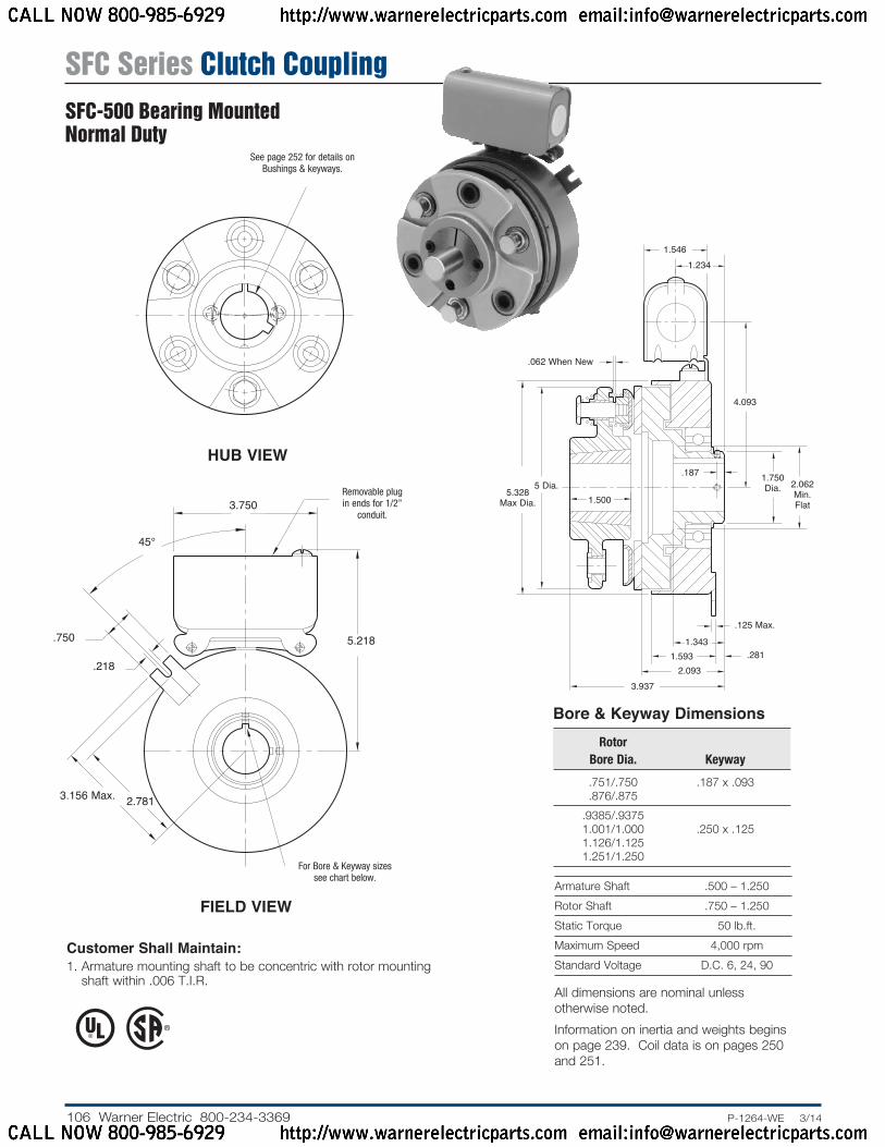
Armature Shaft .500 – 1.250Rotor Shaft .750 – 1.250Static Torque 50 lb.ft.Maximum Speed 4,000 rpmStandard Voltage D.C. 6, 24, 90
Bore & Keyway Dimensions Rotor Bore Dia. Keyway
.751/.750 .187 x .093 .876/.875 .9385/.9375 1.001/1.000 .250 x .125 1.126/1.125 1.251/1.250
HUB VIEW
See page 252 for details on Bushings & keyways.
FIELD VIEW
2.062 Min. Flat
4.093
5 Dia.
.062 When New
.125 Max.
.187
.281
5.328 Max Dia. 1.500
1.750 Dia.
1.5461.234
3.9372.093
1.5931.343
Removable plug in ends for 1/2”
conduit.
3.156 Max. 2.781
.750
.218
5.218
45°
3.750
For Bore & Keyway sizes see chart below.
Customer Shall Maintain:1. Armature mounting shaft to be concentric with rotor mounting
shaft within .006 T.I.R.All dimensions are nominal unless otherwise noted.Information on inertia and weights begins on page 239. Coil data is on pages 250 and 251.
SFC Series Clutch CouplingSFC-500 Bearing MountedNormal Duty
CALL NOW 800-985-6929 http://www.warnerelectricparts.com email:[email protected]
CALL NOW 800-985-6929 http://www.warnerelectricparts.com email:[email protected]
107.P-1264-WE 3/14..... Warner Electric 800-234-3369
3
1
25-2-1
5-4
6
5-3
5-2
5 (Shipped Assembled)
5-1
4
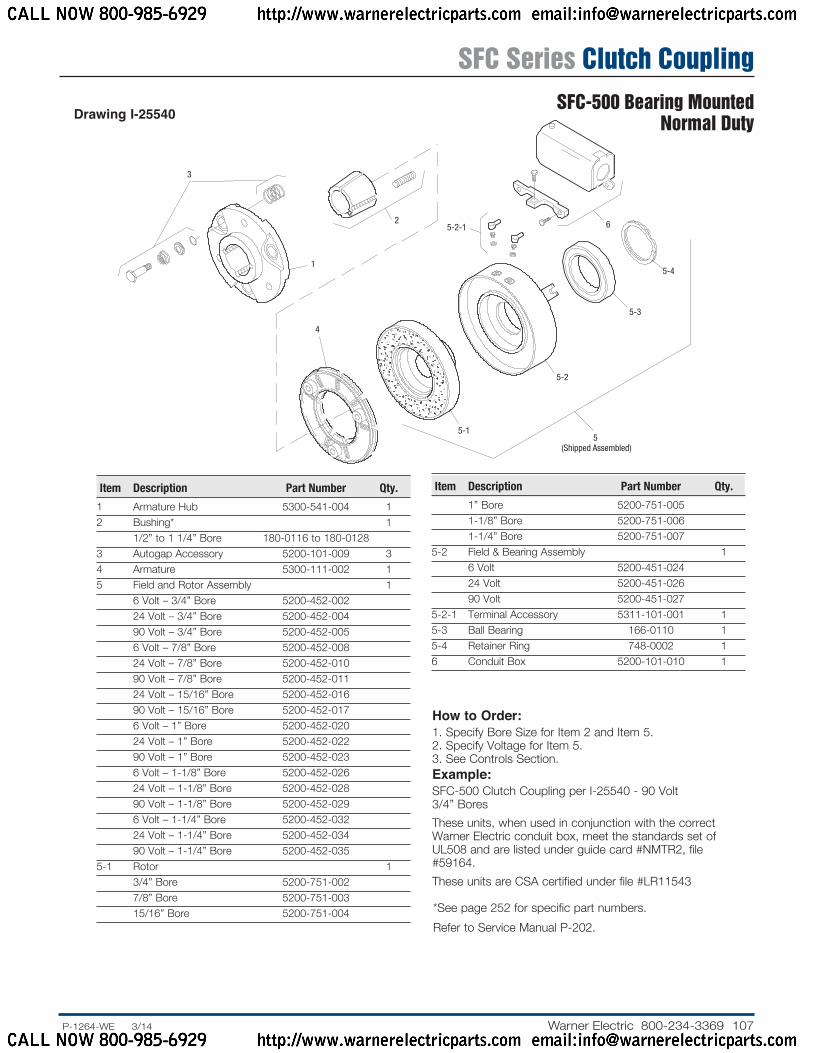
Drawing I-25540
Item Description Part Number Qty.
1 Armature Hub 5300-541-004 12 Bushing* 1 1/2” to 1 1/4” Bore 180-0116 to 180-0128 3 Autogap Accessory 5200-101-009 34 Armature 5300-111-002 15 Field and Rotor Assembly 1 6 Volt – 3/4” Bore 5200-452-002 24 Volt – 3/4” Bore 5200-452-004 90 Volt – 3/4” Bore 5200-452-005 6 Volt – 7/8” Bore 5200-452-008 24 Volt – 7/8” Bore 5200-452-010 90 Volt – 7/8” Bore 5200-452-011 24 Volt – 15/16” Bore 5200-452-016 90 Volt – 15/16” Bore 5200-452-017 6 Volt – 1” Bore 5200-452-020 24 Volt – 1” Bore 5200-452-022 90 Volt – 1” Bore 5200-452-023 6 Volt – 1-1/8” Bore 5200-452-026 24 Volt – 1-1/8” Bore 5200-452-028 90 Volt – 1-1/8” Bore 5200-452-029 6 Volt – 1-1/4” Bore 5200-452-032 24 Volt – 1-1/4” Bore 5200-452-034 90 Volt – 1-1/4” Bore 5200-452-0355-1 Rotor 1 3/4” Bore 5200-751-002 7/8” Bore 5200-751-003 15/16” Bore 5200-751-004
How to Order:1. Specify Bore Size for Item 2 and Item 5.2. Specify Voltage for Item 5.3. See Controls Section.Example:SFC-500 Clutch Coupling per I-25540 - 90 Volt 3/4” BoresThese units, when used in conjunction with the correct Warner Electric conduit box, meet the standards set of UL508 and are listed under guide card #NMTR2, file #59164.These units are CSA certified under file #LR11543
Item Description Part Number Qty.
1” Bore 5200-751-005 1-1/8” Bore 5200-751-006 1-1/4” Bore 5200-751-0075-2 Field & Bearing Assembly 1 6 Volt 5200-451-024 24 Volt 5200-451-026 90 Volt 5200-451-0275-2-1 Terminal Accessory 5311-101-001 15-3 Ball Bearing 166-0110 15-4 Retainer Ring 748-0002 16 Conduit Box 5200-101-010 1
* See page 252 for specific part numbers. Refer to Service Manual P-202.
SFC Series Clutch CouplingSFC-500 Bearing Mounted
Normal Duty
CALL NOW 800-985-6929 http://www.warnerelectricparts.com email:[email protected]
CALL NOW 800-985-6929 http://www.warnerelectricparts.com email:[email protected]

108 Warner Electric 800-234-3369 ......P-1264-WE 3/14
Customer Shall Maintain:1. Angular alignment of shafts within 1/2 degree.2. Armature mounting shaft to be concentric with rotor
mount ing shaft within .006 T.I.R.
Armature Shaft .750 – 1.250Rotor Shaft .750 – 1.250Static Torque 50 lb.ft.Maximum Speed 4,000 rpmStandard Voltage D.C. 6, 24, 90
Bore & Keyway Di men sions Bore Dia. Keyway
.751/.750 .187 x .093 .876/.875 .9385/.9375 1.001/1.000 .250 x .125 1.126/1.125 1.251/1.250
For Bore & Keyway sizes see chart
below.
ARMATURE VIEW
FIELD VIEW
2.062 Min. Flat
4.093
.062 When New
.125
.187
.281
5.328 Max. Dia.
5.125 Dia.
1.203
1.5461.234
1.75 Dia.
.171 Max.
.375
3.2182.093
1.5931.343
3.156 Max. 2.781
Removable plug in ends for 1/2”
conduit.
.750
.218
5.218
45°
3.750
For Bore & Keyway sizes see chart below.
All dimensions are nominal unless otherwise noted.Information on inertia and weights begins on page 239. Coil data is on pages 250 and 251.
SFC Series Clutch CouplingSFC-500 Bearing MountedHeavy Duty
CALL NOW 800-985-6929 http://www.warnerelectricparts.com email:[email protected]
CALL NOW 800-985-6929 http://www.warnerelectricparts.com email:[email protected]

109.P-1264-WE 3/14..... Warner Electric 800-234-3369
1
2B-2
2B-5
2B-4
2B(Shipped Assembled)
2B-3
2B-1
3-2-14
3-4
3-3
3-2
3(Shipped Assembled) 3-1
Drawing I-25541
How to Order:1. Specify Bore Size for Item 1 and Item 3.2. Specify Voltage for Item 3.3. See Controls Section.Example:SFC-500 Clutch Coupling per I-25541- 90 Volt 3/4” Armature Hub Bore 7/8” Rotor BoreThese units, when used in conjunction with the correct Warner Electric conduit box, meet standards set forth in UL508 and are listed under guide card #NMTR2, file #59164.These units are CSA certified under file #LR11543
Item Description Part Number Qty.
1 Armature Hub Assembly 1 3/4” Bore 5200-541-002 7/8” Bore 5200-541-003 15/16” Bore 5200-541-004 1” Bore 5200-541-005 1-1/8” Bore 5200-541-006 1-1/4” Bore 5200-541-0072B Armature Assembly w/Autogap 5230-111-002 12B-1 Armature 5230-111-001 12B-2 Retainer Ring 748-0355 12B-3 Autogap Spring 808-0412 12B-4 Retainer Plate 748-0364 12B-5 Screw 797-0028 33 Field and Rotor Assembly 1 6 Volt – 3/4” Bore 5200-452-002 24 Volt – 3/4” Bore 5200-452-004 90 Volt – 3/4” Bore 5200-452-005 6 Volt – 7/8” Bore 5200-452-008 24 Volt – 7/8” Bore 5200-452-010 90 Volt – 7/8” Bore 5200-452-011 24 Volt – 15/16” Bore 5200-452-016 90 Volt – 15/16” Bore 5200-452-017 6 Volt – 1” Bore 5200-452-020 24 Volt – 1” Bore 5200-452-022 90 Volt – 1” Bore 5200-452-023 6 Volt – 1-1/8” Bore 5200-452-026 24 Volt – 1-1/8” Bore 5200-452-028 90 Volt – 1-1/8” Bore 5200-452-029 6 Volt – 1-1/4” Bore 5200-452-032 24 Volt – 1-1/4” Bore 5200-452-034 90 Volt – 1-1/4” Bore 5200-452-035
Item Description Part Number Qty.
3-1 Rotor 1 3/4” Bore 5200-751-002 7/8” Bore 5200-751-003 15/16” Bore 5200-751-004 1” Bore 5200-751-005 1-1/8” Bore 5200-751-006 1-1/4” Bore 5200-751-0073-2 Field & Bearing Assembly 1 6 Volt 5200-451-024 24 Volt 5200-451-026 90 Volt 5200-451-0273-2-1 Terminal Accessory 5311-101-001 13-3 Ball Bearing 166-0110 13-4 Retainer Ring 748-0002 14 Conduit Box 5200-101-010 1
Refer to Service Manual P-202.
SFC Series Clutch CouplingSFC-500 Bearing Mounted
Heavy Duty
CALL NOW 800-985-6929 http://www.warnerelectricparts.com email:[email protected]
CALL NOW 800-985-6929 http://www.warnerelectricparts.com email:[email protected]
110 Warner Electric 800-234-3369 ......P-1264-WE 3/14
Customer Shall Maintain:1. Concentricity of field mounting pilot diameter with rotor
mounting shaft within .006 T.I.R.2. Squareness of field mounting face with shaft within .006 T.I.R.
measured at field mounting bolt circle.3. Rotor mounting pilot diameter must be concentric with shaft
within .006 T.I.R.4. Armature mounting shaft to be concentric with rotor
mount ing shaft within .006 T.I.R.
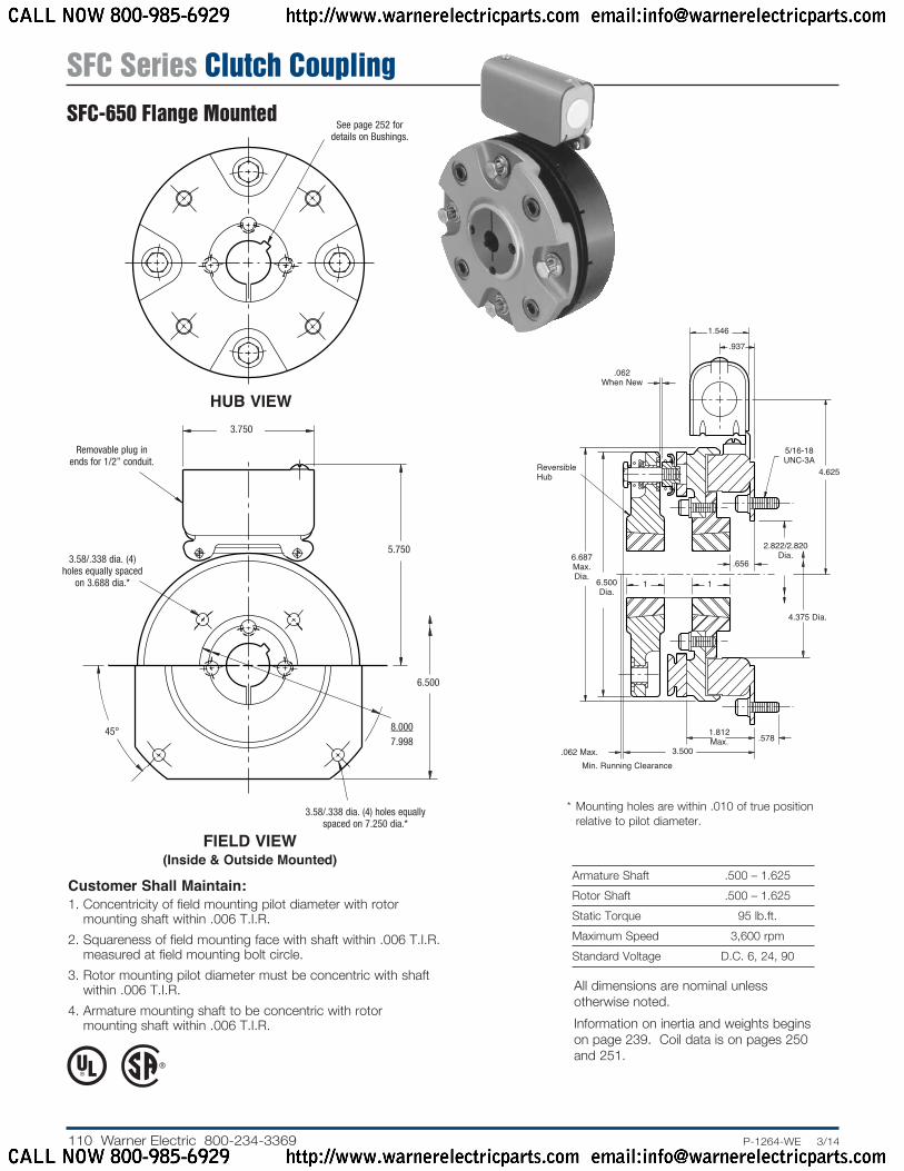
Armature Shaft .500 – 1.625Rotor Shaft .500 – 1.625Static Torque 95 lb.ft.Maximum Speed 3,600 rpmStandard Voltage D.C. 6, 24, 90
HUB VIEW
See page 252 for details on Bushings.
* Mounting holes are within .010 of true position relative to pilot diameter.
.656
1
.062 Max.
2.822/2.820 Dia.
4.625
.062 When New
1.812 Max. .578
1
5/16-18 UNC-3A
Reversible Hub
Min. Running Clearance
4.375 Dia.
6.687 Max. Dia. 6.500
Dia.
3.500
.937
1.546
3.58/.338 dia. (4) holes equally spaced on 7.250 dia.*
45°
5.750
Removable plug in ends for 1/2” conduit.
6.500
8.0007.998
3.58/.338 dia. (4) holes equally spaced
on 3.688 dia.*
3.750
FIELD VIEW(Inside & Outside Mounted)
All dimensions are nominal unless otherwise noted.Information on inertia and weights begins on page 239. Coil data is on pages 250 and 251.
SFC Series Clutch CouplingSFC-650 Flange Mounted
CALL NOW 800-985-6929 http://www.warnerelectricparts.com email:[email protected]
CALL NOW 800-985-6929 http://www.warnerelectricparts.com email:[email protected]
111.P-1264-WE 3/14..... Warner Electric 800-234-3369
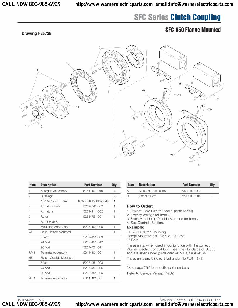
Item Description Part Number Qty.
1 Autogap Accessory 5181-101-010 42 Bushing* 2 1/2” to 1-5/8” Bore 180-0326 to 180-0344 13 Armature Hub 5207-541-002 14 Armature 5281-111-002 15 Rotor 5281-751-001 16 Rotor Hub & Mounting Accessory 5207-101-005 17A Field - Inside Mounted 1 6 Volt 5207-451-009 24 Volt 5207-451-012 90 Volt 5207-451-0117A-1 Terminal Accessory 5311-101-001 17B Field - Outside Mounted 1 6 Volt 5207-451-003 24 Volt 5207-451-006 90 Volt 5207-451-0057B-1 Terminal Accessory 5311-101-001 1
How to Order:1. Specify Bore Size for Item 2 (both shafts).2. Specify Voltage for Item 7.3. Specify Inside or Outside Mounted for Item 7.4. See Controls Section.Example:SFC-650 Clutch Coupling Flange Mounted per I-25728 - 90 Volt 1” BoreThese units, when used in conjunction with the correct Warner Electric conduit box, meet the standards of UL508 and are listed under guide card #NMTR, file #59164.These units are CSA certified under file #LR11543.
Item Description Part Number Qty.
8 Mounting Accessory 5321-101-002 19 Conduit Box 5200-101-010 1
1
4
2
3
5
6
9
9
7A
7A-1
8
2
7B-1
7B
8
Drawing I-25728
* See page 252 for specific part numbers. Refer to Service Manual P-202.
SFC Series Clutch CouplingSFC-650 Flange Mounted
CALL NOW 800-985-6929 http://www.warnerelectricparts.com email:[email protected]
CALL NOW 800-985-6929 http://www.warnerelectricparts.com email:[email protected]

112 Warner Electric 800-234-3369 ......P-1264-WE 3/14
Armature Shaft .500 – 1.625Rotor Shaft .500 – 1.500Static Torque 95 lb.ft.Maximum Speed 3,600 rpmStandard Voltage D.C. 6, 24, 90Customer Shall Maintain:
1. Armature mounting shaft to be concentric with rotor mounting shaft within .006 T.I.R.
HUB VIEW
See page 252 for details on Bushings.
FIELD VIEW
45°
5.750
Removable plug in ends for 1/2” conduit.
.312
3.750
3.750
See page 252 for details on Bushings.
.156
.421.765
.062
4.625
6.359 Dia.
.937
.062
1/4-20 UNC-2A
Reversible Hub
When New
Min. Running Clearance
3.6253.500
1.781
1.2501.00
1.7506.687 Max. Dia.
6.500 Dia.
1.546
Reverse Mounting
All dimensions are nominal unless otherwise noted.Information on inertia and weights begins on page 239. Coil data is on pages 250 and 251.
SFC Series Clutch CouplingSFC-650 Bearing Mounted
CALL NOW 800-985-6929 http://www.warnerelectricparts.com email:[email protected]
CALL NOW 800-985-6929 http://www.warnerelectricparts.com email:[email protected]
113.P-1264-WE 3/14..... Warner Electric 800-234-3369
1
4
2
3
5-7
8
5-5
5-6
5-4-1
5-4
5-35-2
65-1
7
5
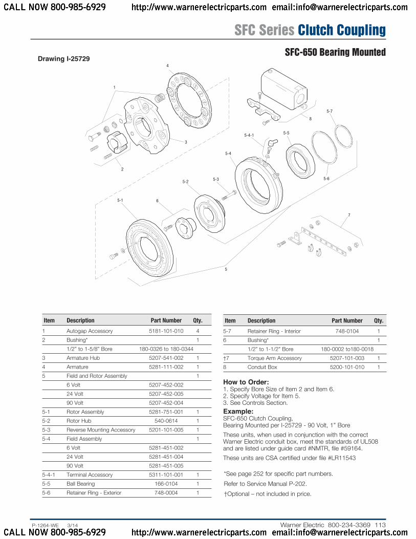
Drawing I-25729
How to Order:1. Specify Bore Size of Item 2 and Item 6.2. Specify Voltage for Item 5.3. See Controls Section.Example:SFC-650 Clutch Coupling, Bearing Mounted per I-25729 - 90 Volt, 1” BoreThese units, when used in conjunction with the correct Warner Electric conduit box, meet the standards of UL508 and are listed under guide card #NMTR, file #59164.These units are CSA certified under file #LR11543
Item Description Part Number Qty.
1 Autogap Accessory 5181-101-010 42 Bushing* 1 1/2” to 1-5/8” Bore 180-0326 to 180-0344 3 Armature Hub 5207-541-002 14 Armature 5281-111-002 15 Field and Rotor Assembly 1 6 Volt 5207-452-002 24 Volt 5207-452-005 90 Volt 5207-452-0045-1 Rotor Assembly 5281-751-001 15-2 Ro tor Hub 540-0614 15-3 Reverse Mounting Accessory 5201-101-005 15-4 Field Assembly 1 6 Volt 5281-451-002 24 Volt 5281-451-004 90 Volt 5281-451-0055-4-1 Terminal Accessory 5311-101-001 15-5 Ball Bearing 166-0104 15-6 Retainer Ring - Exterior 748-0004 1
Item Description Part Num ber Qty.
5-7 Retainer Ring - Interior 748-0104 16 Bushing* 1 1/2” to 1-1/2” Bore 180-0002 to180-0018 †7 Torque Arm Accessory 5207-101-003 18 Conduit Box 5200-101-010 1
* See page 252 for specific part numbers. Refer to Service Manual P-202.† Optional – not included in price.
SFC Series Clutch CouplingSFC-650 Bearing Mounted
CALL NOW 800-985-6929 http://www.warnerelectricparts.com email:[email protected]
CALL NOW 800-985-6929 http://www.warnerelectricparts.com email:[email protected]

114 Warner Electric 800-234-3369 ......P-1264-WE 3/14
Customer Shall Maintain:1. Concentricity of field mounting pilot diameter with rotor
mounting shaft within .006 T.I.R.2. Squareness of field mounting face with rotor shaft within .006
T.I.R. mea sured at field mounting bolt circle.3. Rotor mounting shaft concentric with ar ma ture mounting
shaft within .006 T.I.R.4. Angular alignment of shafts wtihin 1/2 degree.
Armature Shaft .500 – 1.500Rotor Shaft .500 – 1.250Static Torque 125 lb. ft.Maximum Speed 4,000 rpmStandard Voltage D.C. 6, 24, 90
* Mounting holes are within .010 of true po si tion relative to pilot diameter.
** Mounting holes are within .008 of true po si tion relative to pilot diameter.
See page 252 for details on Bushings.
ARMATURE VIEW
FIELD VIEW(Inside & Outside Mounted)
Removable plug in ends for 1/2” conduit.
3.503/3.501 Pilot Dia.
3.750 Max.
6.812
.358/.338 dia. (6) holes equally spaced
on 4.250 dia. *
.358/.338 dia. (4) holes equally
spaced on 8.875 dia. * 9.749/9.747
Pilot Dia..350/.341 dia.
(6) holes equally spaced on 2.875
dia. **
.281
1.250
.602/.586
.562 Max.
5.656
.687
.156
.062
.5311.312
.921
1.546
5/16-18 UNC-3A
8.656 Max. Dia. 4.250
Dia.2.500 Dia. 1.00
2.2532.251 Pilot Dia.
4.406 Max.
1.765
All dimensions are nominal unless otherwise noted.Information on inertia and weights begins on page 239. Coil data is on pages 250 and 251.
Note: The two mating shafts on which the clutch is mounted must be mounted rigidly to prevent flexing during engagement. Any flexing will cause vibration and rapid clutchwear. The drive motor should not be mounted on the reducer “scoop” mount or other flexible mounts.
SFC Series Clutch CouplingSFC-825 Flange Mounted
CALL NOW 800-985-6929 http://www.warnerelectricparts.com email:[email protected]
CALL NOW 800-985-6929 http://www.warnerelectricparts.com email:[email protected]
115.P-1264-WE 3/14..... Warner Electric 800-234-3369
1
2
3
4-1
4-24-3
4(Shipped Assembled)
4-4
4-6
4-5
9A
10A
11
9B
8
76
5
10B
11
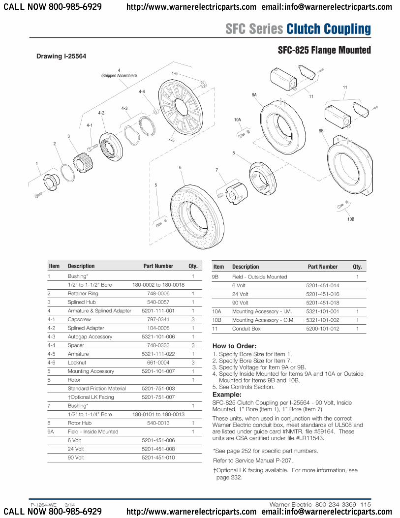
Drawing I-25564
Item Description Part Number Qty.
1 Bushing* 1 1/2” to 1-1/2” Bore 180-0002 to 180-0018 2 Retainer Ring 748-0006 13 Splined Hub 540-0057 14 Armature & Splined Adapter 5201-111-001 14-1 Capscrew 797-0341 34-2 Splined Adapter 104-0008 14-3 Autogap Accessory 5321-101-006 14-4 Spacer 748-0333 34-5 Armature 5321-111-022 14-6 Locknut 661-0004 35 Mounting Accessory 5201-101-007 16 Rotor 1 Standard Friction Material 5201-751-003 †Optional LK Facing 5201-751-007 7 Bushing* 1 1/2” to 1-1/4” Bore 180-0101 to 180-0013 8 Rotor Hub 540-0013 19A Field - Inside Mounted 1 6 Volt 5201-451-006 24 Volt 5201-451-008 90 Volt 5201-451-010
Item Description Part Number Qty.
9B Field - Outside Mounted 1 6 Volt 5201-451-014 24 Volt 5201-451-016 90 Volt 5201-451-01810A Mounting Accessory - I.M. 5321-101-001 110B Mounting Accessory - O.M. 5321-101-002 111 Conduit Box 5200-101-012 1
How to Order:1. Specify Bore Size for Item 1.2. Specify Bore Size for Item 7.3. Specify Voltage for Item 9A or 9B.4. Specify Inside Mounted for Items 9A and 10A or Outside
Mounted for Items 9B and 10B.5. See Con trols Section.Example:SFC-825 Clutch Coupling per I-25564 - 90 Volt, Inside Mounted, 1” Bore (Item 1), 1” Bore (Item 7)These units, when used in conjunction with the correct Warner Electric conduit box, meet standards of UL508 and are listed under guide card #NMTR, file #59164. These units are CSA certified under file #LR11543.
* See page 252 for specific part numbers. Refer to Service Manual P-207.† Optional LK facing available. For more information, see page 232.
SFC Series Clutch CouplingSFC-825 Flange Mounted
CALL NOW 800-985-6929 http://www.warnerelectricparts.com email:[email protected]
CALL NOW 800-985-6929 http://www.warnerelectricparts.com email:[email protected]
116 Warner Electric 800-234-3369 ......P-1264-WE 3/14
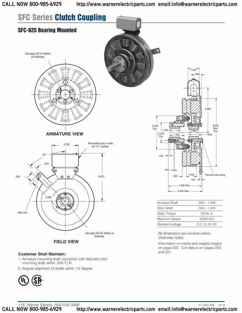
Customer Shall Maintain:1. Armature mounting shaft concentric with field and rotor
mounting shaft within .006 T.I.R.2. Angular alignment of shafts within 1/2 degree.
ARMATURE VIEW
See page 252 for details on Bushings.
FIELD VIEW
Armature Shaft .500 – 1.500Rotor Shaft .500 – 1.500Static Torque 150 lb. ft.Maximum Speed 3,600 rpmStandard Voltage D.C. 6, 24, 90
5.656
.9841.546
.156
.562 1.296
1.6561.250
Reverse Mounting
.187
4.250 Dia.
2.500 Dia.
1.250
1.765
8.656 Max. Dia.
.062
4.468 Max.
4.562 Max.
Removable plug in ends for 1/2” conduit.
45°
6.812.343
.350/.342
See page 252 for details on Bushings.
3.750
.875
5.000
All dimensions are nominal unless otherwise noted.Information on inertia and weights begins on page 239. Coil data is on pages 250 and 251.
SFC Series Clutch CouplingSFC-825 Bearing Mounted
CALL NOW 800-985-6929 http://www.warnerelectricparts.com email:[email protected]
CALL NOW 800-985-6929 http://www.warnerelectricparts.com email:[email protected]

117.P-1264-WE 3/14..... Warner Electric 800-234-3369
1 3
2
4-1
4-2
4-3
4(Shipped Assembled)
4-44-6
4-5
1
5-1 5-2
5-3
6
5-45-5
5(Shipped Assembled)
Drawing I-25574
How to Order:1. Specify Bore Size for Item 1 (both shafts).2. Specify Voltage for Item 5.3. See Controls Section.Example:SFC-825 Clutch Coupling per I-25574 - 90 Volt, 1” BoreThese units, when used in conjunction with the correct Warner Electric conduit box, meet the standards of UL508 and are listed under guide card #NMTR, file #59164. These units are CSA certified under file #LR11543.
Item Description Part Number Qty.
1 Bushing* 2 1/2” to 1-1/2” Bore 180-0002 to 180-0018 2 Retainer Ring 748-0006 13 Splined Hub 540-0057 14 Armature & Splined Adapter 5201-111-001 14-1 Capscrew 797-0341 34-2 Splined Adapter 104-0008 14-3 Autogap Accessory 5321-101-006 14-4 Spacer 748-0333 34-5 Armature 5321-111-022 14-6 Locknut 661-0004 35 Field & Rotor Assembly 1 6 Volt 5201-452-002 24 Volt 5201-452-004 90 Volt 5201-452-0065-1 Rotor 1 Standard Friction Material 5201-751-0085-2 Mounting Accessory 5201-101-005 15-3 Field 1 6 Volt 5201-451-054 24 Volt 5201-451-056 90 Volt 5201-451-057
Item Description Part Number Qty.
5-4 Retainer Ring 748-0111 15-5 Retainer Ring 748-0016 16 Conduit Box 5200-101-012 1
* See page 252 for specific part numbers. Refer to Service Manual P-207.
SFC Series Clutch CouplingSFC-825 Bearing Mounted
CALL NOW 800-985-6929 http://www.warnerelectricparts.com email:[email protected]
CALL NOW 800-985-6929 http://www.warnerelectricparts.com email:[email protected]
118 Warner Electric 800-234-3369 ......P-1264-WE 3/14
Customer Shall Maintain:1. Concentricity of field mounting pilot diameter with rotor
mounting shaft within .006 T.I.R.2. Squareness of field mounting face with rotor shaft within .006
T.I.R. mea sured at field mounting bolt circle.3. Rotor mounting shaft concentric with ar ma ture mounting
shaft within .006 T.I.R.4. Angular alignment of shafts wtihin 1/2 degree.
Armature Shaft .750 – 2.687Rotor Shaft .500 – 2.000Static Torque 240 lb. ft.Maximum Speed 3,600 rpmStandard Voltage D.C. 6, 24, 90
* Mounting holes are within .010 of true po si tion relative to pilot diameter.
** Mounting holes are within .008 of true po si tion relative to pilot diameter.
See page 252 for details on Bushings.
ARMATURE VIEW
FIELD VIEW(Inside & Outside Mounted)
Removable plug in ends for 1/2” conduit.
5.378/5.376 Pilot Dia.
3.750 Max.
7.687
.358/.338 dia. (6) holes equally spaced on 6.125
dia. *
.358/.338 dia. (8) holes
equally spaced on 10.625
dia. *11.500/11.498
Pilot Dia..350/.341 dia. (6) holes equally spaced on 4.875
dia. **
.093
2.500
.570/.554
.562 Max.
6.531
.250
.234
.062
.5001.375
.921
1.546
5/16-18 UNC-3A
10.328 Max. Dia. 6.000
Dia.4.093 Dia. 1.250
4.1284.126 Pilot Dia.
5.359 Max.
2.687
All dimensions are nominal unless otherwise noted.Information on inertia and weights begins on page 239. Coil data is on pages 250 and 251.
Note: The two mating shafts on which the clutch is mounted must be mounted rigidly to prevent flexing during engagement. Any flexing will cause vibration and rapid clutchwear. The drive motor should not be mounted on the reducer “scoop” mount or other flexible mounts.
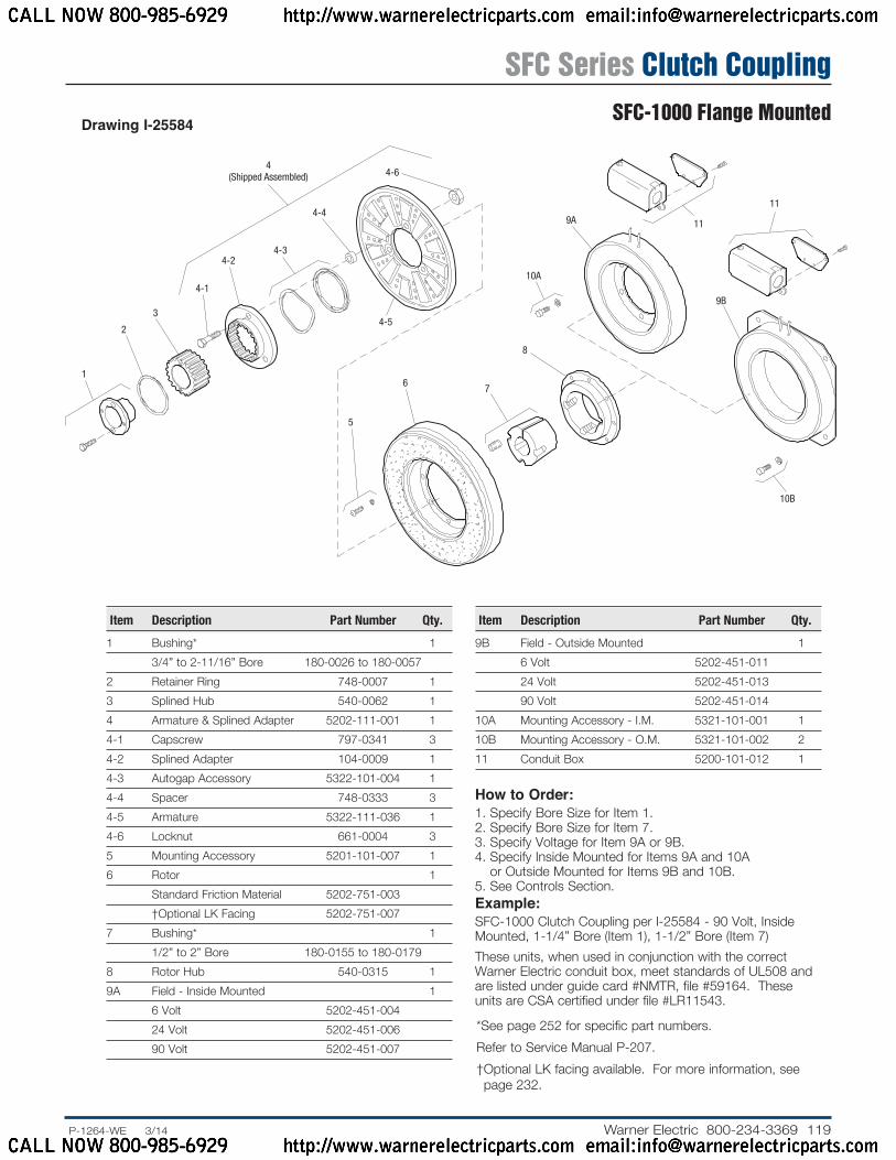
SFC Series Clutch CouplingSFC-1000 Flange Mounted
CALL NOW 800-985-6929 http://www.warnerelectricparts.com email:[email protected]
CALL NOW 800-985-6929 http://www.warnerelectricparts.com email:[email protected]
119.P-1264-WE 3/14..... Warner Electric 800-234-3369
1
2
3
4-1
4-24-3
4(Shipped Assembled)
4-4
4-6
4-5
9A
10A
11
9B
8
76
5
10B
11
Drawing I-25584
Item Description Part Number Qty.
1 Bushing* 1 3/4” to 2-11/16” Bore 180-0026 to 180-0057 2 Retainer Ring 748-0007 13 Splined Hub 540-0062 14 Armature & Splined Adapter 5202-111-001 14-1 Capscrew 797-0341 34-2 Splined Adapter 104-0009 14-3 Autogap Accessory 5322-101-004 14-4 Spacer 748-0333 34-5 Armature 5322-111-036 14-6 Locknut 661-0004 35 Mounting Accessory 5201-101-007 16 Rotor 1 Standard Friction Material 5202-751-003 †Optional LK Facing 5202-751-0077 Bushing* 1 1/2” to 2” Bore 180-0155 to 180-0179 8 Rotor Hub 540-0315 19A Field - Inside Mounted 1 6 Volt 5202-451-004 24 Volt 5202-451-006 90 Volt 5202-451-007
Item Description Part Number Qty.
9B Field - Outside Mounted 1 6 Volt 5202-451-011 24 Volt 5202-451-013 90 Volt 5202-451-01410A Mounting Accessory - I.M. 5321-101-001 110B Mounting Accessory - O.M. 5321-101-002 211 Conduit Box 5200-101-012 1
How to Order:1. Specify Bore Size for Item 1.2. Specify Bore Size for Item 7.3. Specify Voltage for Item 9A or 9B.4. Specify Inside Mounted for Items 9A and 10A
or Outside Mounted for Items 9B and 10B.5. See Con trols Section.Example:SFC-1000 Clutch Coupling per I-25584 - 90 Volt, Inside Mount ed, 1-1/4” Bore (Item 1), 1-1/2” Bore (Item 7)These units, when used in conjunction with the correct Warner Electric conduit box, meet standards of UL508 and are listed under guide card #NMTR, file #59164. These units are CSA certified under file #LR11543.
* See page 252 for specific part numbers. Refer to Service Manual P-207.† Optional LK facing available. For more information, see page 232.
SFC Series Clutch CouplingSFC-1000 Flange Mounted
CALL NOW 800-985-6929 http://www.warnerelectricparts.com email:[email protected]
CALL NOW 800-985-6929 http://www.warnerelectricparts.com email:[email protected]
120 Warner Electric 800-234-3369 ......P-1264-WE 3/14
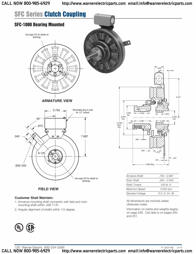
Customer Shall Maintain:1. Armature mounting shaft concentric with field and rotor
mounting shaft within .006 T.I.R.2. Angular alignment of shafts within 1/2 degree.
ARMATURE VIEW
See page 252 for details on Bushings.
FIELD VIEW
Armature Shaft .750 – 2.687Rotor Shaft .500 – 2.000Static Torque 240 lb. ft.Maximum Speed 2,500 rpmStandard Voltage D.C. 6, 24, 90
Removable plug in ends for 1/2” conduit.
45°
7.687.343
.350/.342
See page 252 for details on Bushings.
3.750
.875
6.125
6.531
1.4211.546
.234
.062
.5621.375
.187.437
1.2502.562 Dia.
2.0622.687
2.500
10.328 Max. Dia.
6.000 Dia.
4.093 Dia.
5.890 Max.
All dimensions are nominal unless otherwise noted.Information on inertia and weights begins on page 239. Coil data is on pages 250 and 251.
SFC Series Clutch CouplingSFC-1000 Bearing Mounted
CALL NOW 800-985-6929 http://www.warnerelectricparts.com email:[email protected]
CALL NOW 800-985-6929 http://www.warnerelectricparts.com email:[email protected]
121.P-1264-WE 3/14..... Warner Electric 800-234-3369
1
2
3 4-1
4-24-3
4-4
4-5
4(Shipped Assembled)
4-6
6
7 5-5
5-4
5-3
5-10
5-9
5-2
5(Shipped Assembled)
5-7
5-8
5-1
5-6
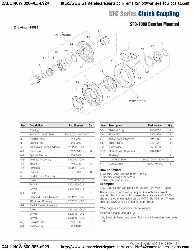
Drawing I-25598
Item Description Part Number Qty.
1 Bushing* 1 3/4” to 2-11/16” Bore 180-0026 to 180-0057 2 Retainer Ring 748-0007 13 Splined Hub 540-0062 14 Armature & Splined Adapter 5202-111-001 14-1 Capscrew 797-0341 34-2 Splined Adapter 104-0009 14-3 Autogap Accessory 5322-101-004 14-4 Spacer 748-0333 34-5 Armature 5322-111-036 14-6 Locknut 661-0004 35 Field & Rotor Assembly 1 6 Volt 5202-452-012 24 Volt 5202-452-014 90 Volt 5202-452-0155-1 Rotor 1 Standard Friction Material 5202-751-003 †Optional LK Facing 5202-751-0075-2 Field & Bearing Assembly 1 6 Volt 5202-451-040 24 Volt 5202-451-042 90 Volt 5202-451-0435-3 Retainer Ring 748-0116 15-4 Ball Bearing 166-1046 1
Item Description Part Number Qty.
5-5 Retainer Ring 748-0582 15-6 Rotor Hub 540-1300 15-7 Buttonhead Capscrew 797-1261 65-8 Ring Adapter 748-1047 15-9 Lockwasher 950-0359 65-10 Socket Head Capscrew 797-0422 66 Bushing* 1 1/2” to 2” Bore 180-0155 to 180-0179 7 Conduit Box 5200-101-012 1
How to Order:1. Specify Bore Size for Items 1 and 6.2. Specify Voltage for Item 5.3. See Controls Section.Example:SFC-1000 Clutch Coupling per I-25598 - 90 Volt, 1” BoreThese units, when used in conjunction with the correct Warner Electric conduit box, meet the standards of UL508 and are listed under guide card #NMTR, file #59164. These units are CSA certified under file #LR11543.
* See page 252 for specific part numbers. Refer to Service Manual P-207.† Optional LK facing available. For more information, see page 232.
SFC Series Clutch CouplingSFC-1000 Bearing Mounted
CALL NOW 800-985-6929 http://www.warnerelectricparts.com email:[email protected]
CALL NOW 800-985-6929 http://www.warnerelectricparts.com email:[email protected]

122 Warner Electric 800-234-3369 ......P-1264-WE 3/14
ARMATURE VIEW
When Hub is Furnished by Customer:Rotor mounting pilot diameter must be concentric with rotor mounting shaft within .006 T.I.R.
Customer Shall Maintain:1. Concentricity of field mounting pilot diameter with rotor
mounting shaft within .006 T.I.R.2. Squareness of field mounting face with rotor mounting shaft
within .006 T.I.R. measured at field mounting bolt circle.3. Rotor mounting shaft concentric with armature mounting
shaft within .006 T.I.R.4. Angular alignment of shafts within 1/2 degree.
Armature Shaft .750 – 2.687Rotor Shaft .500 – 2.500Static Torque 465 lb. ft.Maximum Speed 3,000 rpmStandard Voltage D.C. 6, 24, 90
See page 252 for de tails on
bush ings.
* Mounting holes are within .010 of true position relative to pilot diameter.
** Mounting holes are within .008 of true position relative to pilot diameter.
FIELD VIEW(Inside & Outside Mounted)
.234
.562
.281
.758
.7421.562
.062
.562
1.750 .312
5/16-18 UNC-3A
7.531
.921
1.546
12.703 Max. Dia. 12.625
Dia.7.062 Dia.
4.093 Dia.
2.500
2.6875.4385.436 Pilot Dia.
5.890 Max.
Removable plug in ends for 1/2” conduit.
.350/.341 dia. (8) holes equally spaced on 6.062
dia.**
.358/.338 dia. (8) holes equally spaced on 13.000 dia.*
6.378/6.376 Pilot Dia.
13.875/13.871 Pilot Dia.
3.750
8.687 Max.
.358/.338 dia. (6) holes equally spaced on 7.250 dia.*
All dimensions are nominal unless otherwise noted.Information on inertia and weights begins on page 239. Coil data is on pages 250 and 251.
SFC Series Clutch CouplingSFC-1225 Flange Mounted
CALL NOW 800-985-6929 http://www.warnerelectricparts.com email:[email protected]
CALL NOW 800-985-6929 http://www.warnerelectricparts.com email:[email protected]
123.P-1264-WE 3/14..... Warner Electric 800-234-3369
1
2
3
4-2
4-3
4(Shipped Assembled)
4-4
4-1
4-5
4-6
9A
10A
76
5
810B
9B
11
11
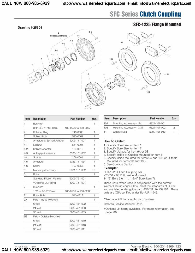
Drawing I-25604
Item Description Part Number Qty.
1 Bushing* 1 3/4” to 2-11/16” Bore 180-0026 to 180-0057 2 Retainer Ring 748-0005 13 Splined Hub 540-0064 14 Armature & Splined Adapter 5203-111-001 14-1 Locknut 661-0004 44-2 Splined Adapter 104-0010 14-3 Autogap Accessory 5323-101-002 14-4 Spacer 266-0004 44-5 Armature 5323-111-034 14-6 Screw 797-0356 45 Mounting Accessory 5321-101-002 26 Rotor 1 Standard Friction Material 5203-751-001 †Optional LK Facing 5203-751-0047 Bushing* 1 1/2” to 2-1/2” Bore 180-0185 to 180-0217 8 Rotor Hub 540-0318 19A Field - Inside Mounted 1 6 Volt 5203-451-002 24 Volt 5203-451-006 90 Volt 5203-451-0059B Field - Outside Mounted 1 6 Volt 5203-451-010 24 Volt 5203-451-013 90 Volt 5203-451-011
Item Description Part Number Qty.
10A Mounting Accessory - I.M. 5321-101-001 110B Mounting Accessory - O.M. 5321-101-002 211 Conduit Box 5200-101-012 1
How to Order:1. Specify Bore Size for Item 1.2. Specify Bore Size for Item 7.3. Specify Voltage for Item 9A or 9B.4. Specify Inside or Outside Mounted for Item 5.5. Specify Inside Mounted for Items 9A and 10A or Outside
Mounted for Items 9B and 10B.6. See Con trols Section.Example:SFC-1225 Clutch Coupling per I-25604 - 90 Volt, Inside Mounted, 1-1/2” Bore (Item 1), 1-3/4” Bore (Item 7).These units, when used in conjunction with the correct Warner Electric conduit box, meet the standards of UL508 and are listed under guide card #NMTR, file #59164. These units are CSA certified under file #LR11543.
* See page 252 for specific part numbers. Refer to Service Manual P-207.† Optional LK facing available. For more information, see
page 232.
SFC Series Clutch CouplingSFC-1225 Flange Mounted
CALL NOW 800-985-6929 http://www.warnerelectricparts.com email:[email protected]
CALL NOW 800-985-6929 http://www.warnerelectricparts.com email:[email protected]
124 Warner Electric 800-234-3369 ......P-1264-WE 3/14
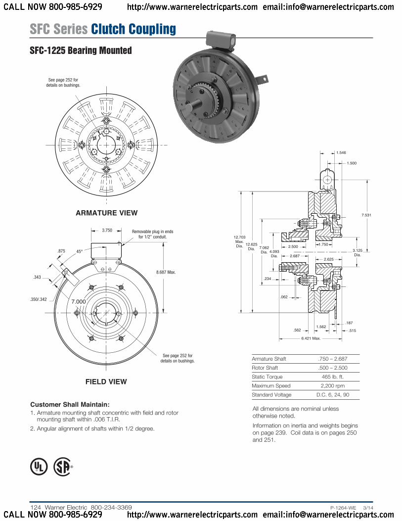
Armature Shaft .750 – 2.687Rotor Shaft .500 – 2.500Static Torque 465 lb. ft.Maximum Speed 2,200 rpmStandard Voltage D.C. 6, 24, 90
Customer Shall Maintain:1. Armature mounting shaft concentric with field and rotor
mounting shaft within .006 T.I.R.2. Angular alignment of shafts within 1/2 degree.
ARMATURE VIEW
FIELD VIEW
7.531
1.500
1.546
.234
.062
.5621.562
.515
.187
12.625 Dia.
12.703 Max. Dia. 7.062
Dia. 4.093 Dia.
2.500 1.7503.125 Dia.
2.6252.687
6.421 Max.
Removable plug in ends for 1/2” con duit.
8.687 Max..343
.875
.350/.342
45°
7.000
3.750
See page 252 for de tails on bush ings.
See page 252 for de tails on bush ings.
All dimensions are nominal unless otherwise noted.Information on inertia and weights begins on page 239. Coil data is on pages 250 and 251.
SFC Series Clutch CouplingSFC-1225 Bearing Mounted
CALL NOW 800-985-6929 http://www.warnerelectricparts.com email:[email protected]
CALL NOW 800-985-6929 http://www.warnerelectricparts.com email:[email protected]
125.P-1264-WE 3/14..... Warner Electric 800-234-3369
1
2
3
4-6
4-2
4-3
4-4
4(Shipped Assembled)
4-1
7
4-5
5-2
5-35-4
5-5
5-10
5-9
5-7
5-8
5-1
5-6
6
5(Shipped Assembled)
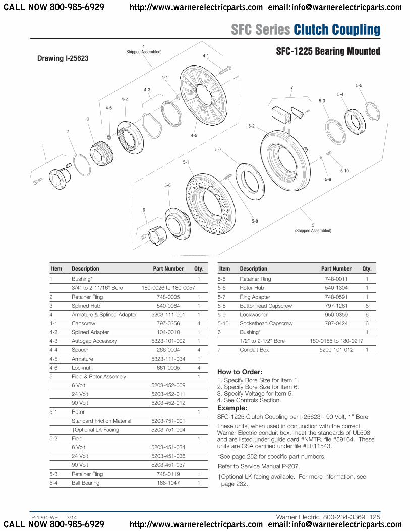
Drawing I-25623
How to Order:1. Specify Bore Size for Item 1.2. Specify Bore Size for Item 6.3. Specify Voltage for Item 5.4. See Controls Section.Example:SFC-1225 Clutch Coupling per I-25623 - 90 Volt, 1” BoreThese units, when used in conjunction with the correct Warner Electric conduit box, meet the standards of UL508 and are listed under guide card #NMTR, file #59164. These units are CSA certified under file #LR11543.
Item Description Part Number Qty.
1 Bushing* 1 3/4” to 2-11/16” Bore 180-0026 to 180-0057 2 Retainer Ring 748-0005 13 Splined Hub 540-0064 14 Armature & Splined Adapter 5203-111-001 14-1 Capscrew 797-0356 44-2 Splined Adapter 104-0010 14-3 Autogap Accessory 5323-101-002 14-4 Spacer 266-0004 44-5 Armature 5323-111-034 14-6 Locknut 661-0005 45 Field & Rotor Assembly 1 6 Volt 5203-452-009 24 Volt 5203-452-011 90 Volt 5203-452-0125-1 Rotor 1 Standard Friction Material 5203-751-001 †Optional LK Facing 5203-751-0045-2 Field 1 6 Volt 5203-451-034 24 Volt 5203-451-036 90 Volt 5203-451-0375-3 Retainer Ring 748-0119 15-4 Ball Bearing 166-1047 1
Item Description Part Number Qty.
5-5 Retainer Ring 748-0011 15-6 Rotor Hub 540-1304 15-7 Ring Adapter 748-0591 15-8 Buttonhead Capscrew 797-1261 65-9 Lockwasher 950-0359 65-10 Sockethead Capscrew 797-0424 66 Bushing* 1 1/2” to 2-1/2” Bore 180-0185 to 180-0217 7 Conduit Box 5200-101-012 1
* See page 252 for specific part numbers. Refer to Service Manual P-207.† Optional LK facing available. For more information, see page 232.
SFC Series Clutch CouplingSFC-1225 Bearing Mounted
CALL NOW 800-985-6929 http://www.warnerelectricparts.com email:[email protected]
CALL NOW 800-985-6929 http://www.warnerelectricparts.com email:[email protected]
126 Warner Electric 800-234-3369 ......P-1264-WE 3/14
ARMATURE VIEW
When Hub is Furnished by Customer:Rotor mounting pilot diameter must be concentric with rotor mounting shaft within .006 T.I.R.
Customer Shall Maintain:1. Concentricity of field mounting pilot diameter with rotor
mounting shaft within .006 T.I.R.2. Squareness of field mounting face with rotor mounting shaft
within .006 T.I.R. measured at field mounting bolt circle.3. Rotor mounting shaft concentric with armature mounting
shaft within .006 T.I.R.4. Angular alignment of shafts within 1/2 degree.
Armature Shaft .750 – 2.687Rotor Shaft .937 – 3.000Static Torque 700 lb. ft.Maximum Speed 2,000 rpmStandard Voltage D.C. 6, 24, 90
See page 252 for de tails on bush ings.
* Mounting holes are within .010 of true position relative to pilot diameter.
** Mounting holes are within .008 of true position relative to pilot diameter.FIELD VIEW
(Inside & Outside Mounted)
.234
.562
.437
.758
.7421.562
.062
.562
2 .218
5/16-18 UNC-3A
9.187
.921
1.546
15.671 Max. Dia. 15.578
Dia.8.750 Dia.
4.093 Dia.
2.500
2.6877.8787.876 Pilot Dia.
6.031 Max.
Removable plug in ends for 1/2” conduit.
.350/.341 dia. (8) holes equally spaced on 8.500 dia.**
.358/.338 dia. (12) holes equally spaced on 16.000 dia.*
9.002/9.000 Pilot Dia.
16.875/16.871 Pilot Dia.
3.750
10.343 Max.
.358/.338 dia. (12) holes equally spaced on 9.750 dia.*
All dimensions are nominal unless otherwise noted.Information on inertia and weights begins on page 239. Coil data is on pages 250 and 251.
SFC Series Clutch CouplingSFC-1525 Flange Mounted
CALL NOW 800-985-6929 http://www.warnerelectricparts.com email:[email protected]
CALL NOW 800-985-6929 http://www.warnerelectricparts.com email:[email protected]
127.P-1264-WE 3/14..... Warner Electric 800-234-3369
1
2
34-1
4-2
4-3
4-4
4-5
4(Shipped Assembled) 4-6
4-7
9A 11
11
9B
10B8
10A
76
5
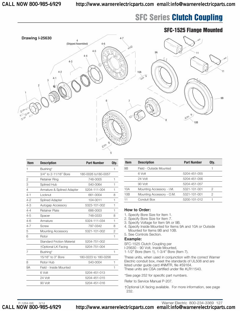
Item Description Part Number Qty.
1 Bushing* 1 3/4” to 2-11/16” Bore 180-0026 to180-0057 2 Retainer Ring 748-0005 13 Splined Hub 540-0064 14 Armature & Splined Adapter 5204-111-004 14-1 Locknut 661-0004 84-2 Splined Adapter 104-0011 14-3 Autogap Accessory 5323-101-002 14-4 Retainer Plate 686-0003 14-5 Spacer 748-0333 84-6 Armature 5324-111-034 14-7 Screw 797-0342 85 Mounting Accessory 5321-101-002 26 Rotor 1 Standard Friction Material 5204-751-002 †Optional LK Facing 5204-751-0047 Bushing* 1 15/16” to 3” Bore 180-0223 to 180-0256 8 Rotor Hub 540-0004 19A Field - Inside Mounted 1 6 Volt 5204-451-013 24 Volt 5204-451-015 90 Volt 5204-451-016
How to Order:1. Specify Bore Size for Item 1.2. Specify Bore Size for Item 7.3. Specify Voltage for Item 9A or 9B.4. Specify Inside Mounted for Items 9A and 10A or Outside
Mounted for Items 9B and 10B.5. See Con trols Section.Example:SFC-1525 Clutch Coupling per I-25630 - 90 Volt, Inside Mounted, 1-1/2” Bore (Item 1), 1-3/4” Bore (Item 7).These units, when used in conjunction with the correct Warner Electric conduit box, meet the standards of UL508 and are listed under guide card #NMTR, file #59164. These units are CSA certified under file #LR11543.
Item Description Part Number Qty.
9B Field - Outside Mounted 1 6 Volt 5204-451-055 24 Volt 5204-451-056 90 Volt 5204-451-05710A Mounting Accessory - I.M. 5321-101-001 210B Mounting Accessory - O.M. 5321-101-001 211 Conduit Box 5200-101-012 1
Drawing I-25630
* See page 252 for specific part numbers. Refer to Service Manual P-207.† Optional LK facing available. For more information, see page 232.
SFC Series Clutch CouplingSFC-1525 Flange Mounted
CALL NOW 800-985-6929 http://www.warnerelectricparts.com email:[email protected]
CALL NOW 800-985-6929 http://www.warnerelectricparts.com email:[email protected]

128 Warner Electric 800-234-3369 ......P-1264-WE 3/14
Armature Shaft .750 – 2.687Rotor Shaft .937 – 3.000Static Torque 700 lb. ft.Maximum Speed 1,800 rpmStandard Voltage D.C. 6, 24, 90
Customer Shall Maintain:1. Armature mounting shaft concentric with field and rotor
mounting shaft within .006 T.I.R.2. Angular alignment of shafts within 1/2 degree.
ARMATURE VIEW
FIELD VIEW
9.187
2.093
1.546
.234
.062
.5621.562
1.125
.187
15.578 Dia.
15.671 Max. Dia. 8.750
Dia. 4.093 Dia.
2.500 2.000 3.968 Dia.
2.9372.687
7.187 Max.
Removable plug in ends for 1/2” con duit.
10.343 Max..343
.875
.350/.342
45°
8.531
3.750
See page 252 for de tails on bush ings.
See page 252 for de tails on bush ings.
All dimensions are nominal unless otherwise noted.Information on inertia and weights begins on page 239. Coil data is on pages 250 and 251.
SFC Series Clutch CouplingSFC-1525 Bearing Mounted
CALL NOW 800-985-6929 http://www.warnerelectricparts.com email:[email protected]
CALL NOW 800-985-6929 http://www.warnerelectricparts.com email:[email protected]
129.P-1264-WE 3/14..... Warner Electric 800-234-3369
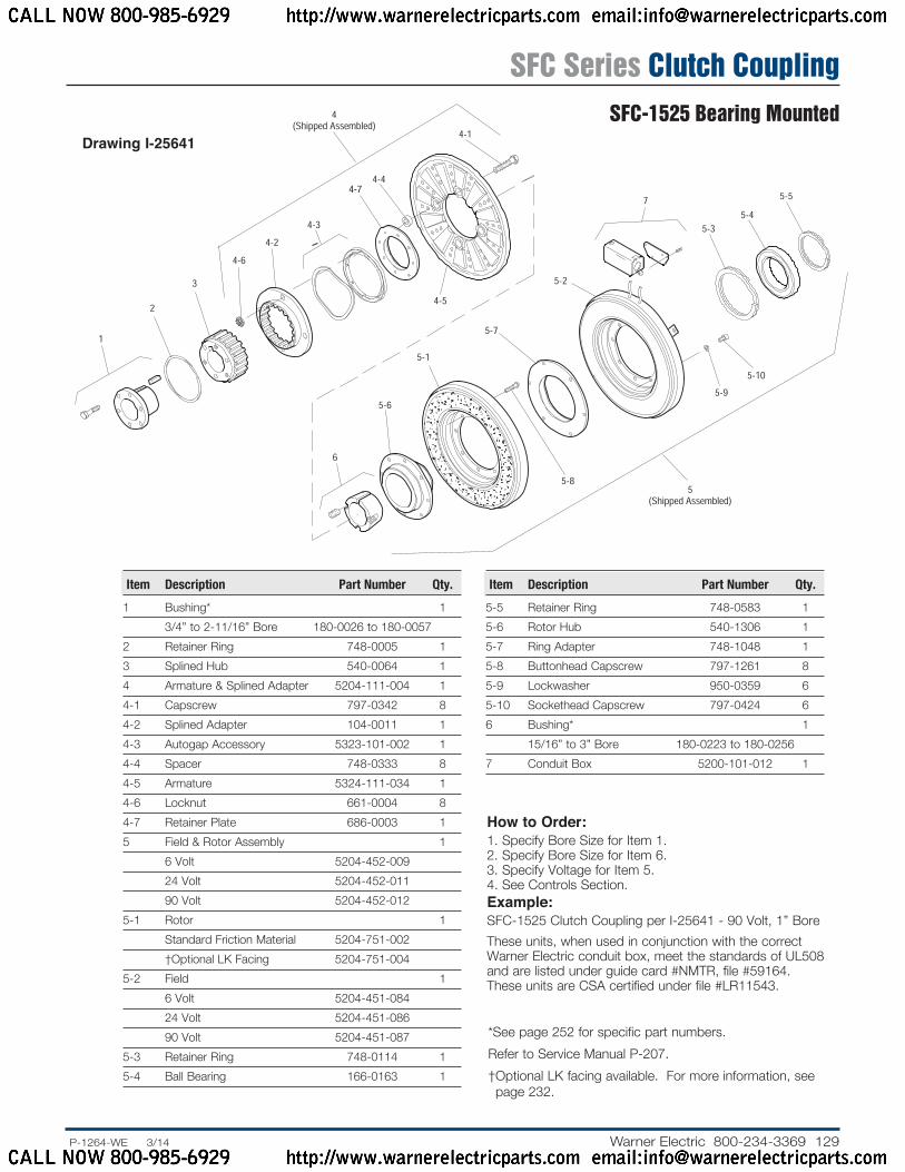
Drawing I-25641
Item Description Part Number Qty.
1 Bushing* 1 3/4” to 2-11/16” Bore 180-0026 to 180-0057 2 Retainer Ring 748-0005 13 Splined Hub 540-0064 14 Armature & Splined Adapter 5204-111-004 14-1 Capscrew 797-0342 84-2 Splined Adapter 104-0011 14-3 Autogap Accessory 5323-101-002 14-4 Spacer 748-0333 84-5 Armature 5324-111-034 14-6 Locknut 661-0004 84-7 Retainer Plate 686-0003 15 Field & Rotor Assembly 1 6 Volt 5204-452-009 24 Volt 5204-452-011 90 Volt 5204-452-0125-1 Rotor 1 Standard Friction Material 5204-751-002 †Optional LK Facing 5204-751-0045-2 Field 1 6 Volt 5204-451-084 24 Volt 5204-451-086 90 Volt 5204-451-0875-3 Retainer Ring 748-0114 15-4 Ball Bearing 166-0163 1
Item Description Part Number Qty.
5-5 Retainer Ring 748-0583 15-6 Rotor Hub 540-1306 15-7 Ring Adapter 748-1048 15-8 Buttonhead Capscrew 797-1261 85-9 Lockwasher 950-0359 65-10 Sockethead Capscrew 797-0424 66 Bushing* 1 15/16” to 3” Bore 180-0223 to 180-0256 7 Conduit Box 5200-101-012 1
How to Order:1. Specify Bore Size for Item 1.2. Specify Bore Size for Item 6.3. Specify Voltage for Item 5.4. See Controls Section.Example:SFC-1525 Clutch Coupling per I-25641 - 90 Volt, 1” BoreThese units, when used in conjunction with the correct Warner Electric conduit box, meet the standards of UL508 and are listed under guide card #NMTR, file #59164. These units are CSA certified under file #LR11543.
* See page 252 for specific part numbers. Refer to Service Manual P-207.† Optional LK facing available. For more information, see page 232.
SFC Series Clutch CouplingSFC-1525 Bearing Mounted
CALL NOW 800-985-6929 http://www.warnerelectricparts.com email:[email protected]
CALL NOW 800-985-6929 http://www.warnerelectricparts.com email:[email protected]
130 Warner Electric 800-234-3369 ......P-1264-WE 3/14
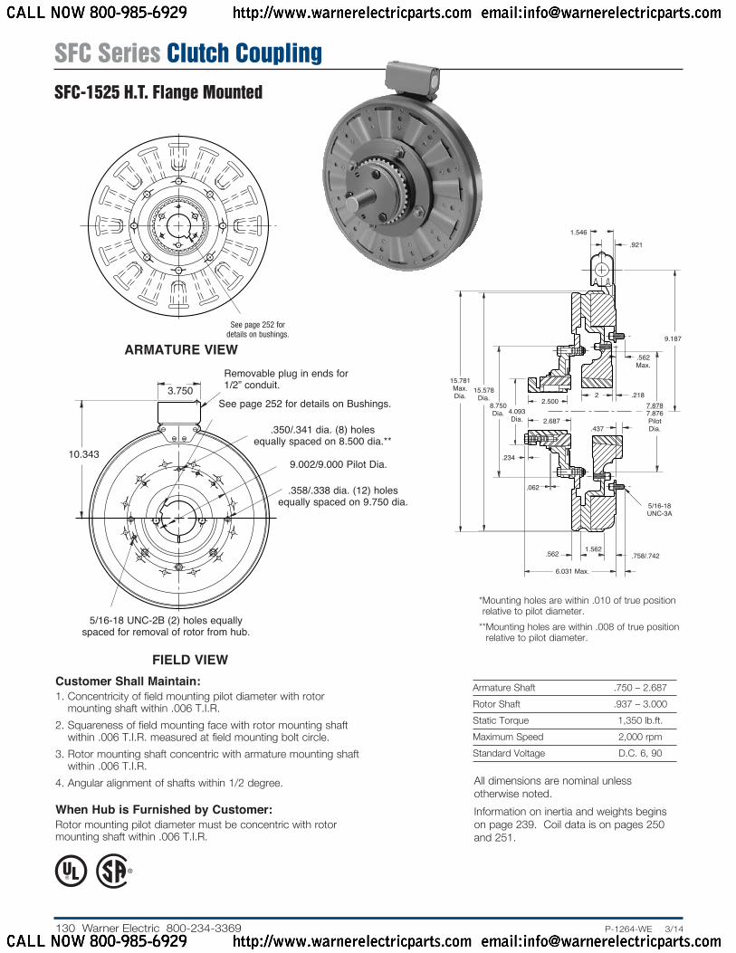
Armature Shaft .750 – 2.687Rotor Shaft .937 – 3.000Static Torque 1,350 lb.ft.Maximum Speed 2,000 rpmStandard Voltage D.C. 6, 90
Customer Shall Maintain:1. Concentricity of field mounting pilot diameter with rotor
mounting shaft within .006 T.I.R.2. Squareness of field mounting face with rotor mounting shaft
within .006 T.I.R. measured at field mounting bolt circle.3. Rotor mounting shaft concentric with armature mounting shaft
within .006 T.I.R.4. Angular alignment of shafts within 1/2 degree.
When Hub is Furnished by Customer:Rotor mounting pilot diameter must be concentric with rotor mounting shaft within .006 T.I.R.
ARMATURE VIEW
See page 252 for de tails on bush ings.
* Mounting holes are within .010 of true position relative to pilot diameter.
** Mounting holes are within .008 of true position relative to pilot diameter.
FIELD VIEW
2 .218
.062
.562 1.562
.437
.758/.742
.562 Max.
5/16-18 UNC-3A
9.187
.921
1.546
2.500
15.781 Max. Dia.
15.578 Dia.
8.750 Dia. 4.093
Dia. 2.687
7.8787.876 Pilot Dia.
.234
6.031 Max.
.350/.341 dia. (8) holesequally spaced on 8.500 dia.**
Removable plug in ends for 1/2” conduit.
9.002/9.000 Pilot Dia.10.343
3.750
.358/.338 dia. (12) holes equally spaced on 9.750 dia.
5/16-18 UNC-2B (2) holes equally spaced for removal of rotor from hub.
See page 252 for details on Bushings.
All dimensions are nominal unless otherwise noted.Information on inertia and weights begins on page 239. Coil data is on pages 250 and 251.
SFC Series Clutch CouplingSFC-1525 H.T. Flange Mounted
CALL NOW 800-985-6929 http://www.warnerelectricparts.com email:[email protected]
CALL NOW 800-985-6929 http://www.warnerelectricparts.com email:[email protected]

131.P-1264-WE 3/14..... Warner Electric 800-234-3369
Drawing I-25631
1
2
3 4-1
4-2
4-3
4(Shipped Assembled)
4-4
4-5
4-64-7
1110
9
8
76
5
Item Description Part Number Qty.
1 Bushing* 1 3/4” to 2-11/16” Bore 180-0026 to 180-0057 2 Retainer Ring 748-0005 13 Splined Hub 540-0064 14 Armature & Splined Adapter 5204-111-004 14-1 Locknut 661-0004 84-2 Splined Adapter 104-0011 14-3 Autogap Accessory 5323-101-002 14-4 Retainer Plate 686-0003 14-5 Spacer 748-0333 84-6 Armature 5324-111-034 14-7 Screw 797-0342 85 Mounting Accessory 5321-101-002 26 Rotor 5204-751-001 17 Bushing* 1 15/16” to 3” Bore 180-0223 to 180-0256 8 Rotor Hub 540-0004 19 Field - Inside Mounted 1 90 Volt 5204-451-006
Item Description Part Number Qty.
10 Mounting Accessory - I.M. 5321-101-001 211 Conduit Box 5200-101-012 1
* See page 252 for specific part numbers. Refer to Service Manual P-207.
How to Order:1. Specify Bore Size for Item 1.2. Specify Bore Size for Item 7.3. See Controls Section.Example:SFC-1525 Clutch Coupling, Hi-Torque, per I-25631 - 90 Volt2” Bore (Item 1), 2-1/2” Bore (Item 7)These units, when used in conjunction with the correct Warner Electric conduit box, meet the standards of UL508 and are listed under guide card #NMTR, file #59164. These units are CSA certified under file #LR11543.
SFC Series Clutch CouplingSFC-1525 H.T. Flange Mounted
CALL NOW 800-985-6929 http://www.warnerelectricparts.com email:[email protected]
CALL NOW 800-985-6929 http://www.warnerelectricparts.com email:[email protected]

132 Warner Electric 800-234-3369 ......P-1264-WE 3/14
Armature Shaft .750 – 2.687Rotor Shaft .937 – 3.000Static Torque 1,350 lb.ft.Maximum Speed 1,800 rpmStandard Voltage D.C. 90
ARMATURE VIEW
Customer Shall Maintain:1. Armature mounting shaft concentric with field
and rotor mount ing shaft within .006 T.I.R.2. Angular alignment of shafts within 1/2 degree.
FIELD VIEW
9.187
2.0931.546
.062
.5621.562
.187
2.000
.234
1.125
7.187 Max.
15.671 Max. Dia.
15.578 Dia. 8.750
Dia. 4.093 Dia.
2.500
2.6872.937
3.968 Dia.
See page 252 for details on Bushings.
Removable plug in ends for 1/2” conduit.
45°
3.750
10.343 Max..343
.875
.350/.342
See page 252 for details on Bushings.
8.531
All dimensions are nominal unless otherwise noted.Information on inertia and weights begins on page 239. Coil data is on pages 250 and 251.
SFC Series Clutch CouplingSFC-1525 H.T. Bearing Mounted
CALL NOW 800-985-6929 http://www.warnerelectricparts.com email:[email protected]
CALL NOW 800-985-6929 http://www.warnerelectricparts.com email:[email protected]

133.P-1264-WE 3/14..... Warner Electric 800-234-3369
Drawing I-25644
How to Order:1. Specify Bore Size for Item 1.2. Specify Bore Size for Item 6.3. Specify Voltage for Item 5.4. See Controls Section.Example:SFC-1525 Clutch Coupling Hi-Torque per I-25644 - 90 Volt, 1” BoreThese units, when used in conjunction with the correct Warner Electric conduit box, meet the standards of UL508 and are listed under guide card #NMTR, file #59164. These units are CSA certified under file #LR11543.
8
9
1-7
1-2
1-3
1-4
1-5
1-6
1-11
2
3
4
5
7
6
10
Item Description Part Number Qty.
1 Bushing* 1 3/4” to 2-11/16” Bore 180-0026 to 180-0057 2 Retainer Ring 748-0005 13 Splined Hub 540-0064 14 Armature & Splined Adapter 5204-111-004 14-1 Capscrew 797-0342 84-2 Splined Adapter 104-0011 14-3 Autogap Accessory 5323-101-002 14-4 Spacer 748-0333 84-5 Armature 5324-111-034 14-6 Locknut 661-0004 84-7 Retainer Plate 686-0003 15 Field & Rotor Assembly 1 90 Volt 5204-452-0155-1 Rotor 5204-751-001 15-2 Field 1 90 Volt 5204-451-0905-3 Retainer Ring 748-0114 15-4 Ball Bearing 166-0163 15-5 Retainer Ring 748-0583 15-6 Rotor Hub 540-1306 15-7 Ring Adapter 748-1048 1
Item Description Part Number Qty.
5-8 Buttonhead Capscrew 797-1261 85-9 Lockwasher 950-0359 65-10 Sockethead Capscrew 797-0424 66 Bushing* 1 5/16” to 3” Bore 180-0223 to 180-0256 7 Conduit Box 5200-101-012 1
* See page 252 for specific part numbers. Refer to Service Manual P-207.
SFC Series Clutch CouplingSFC-1525 H.T. Bearing Mounted
CALL NOW 800-985-6929 http://www.warnerelectricparts.com email:[email protected]
CALL NOW 800-985-6929 http://www.warnerelectricparts.com email:[email protected]