sff-8083 specification - 10gtek · published sff-8083 rev 2.5 ... eia 364-21 insulation resistance...
TRANSCRIPT
Published SFF-8083 Rev 2.5
0.8mm Card Edge Connector for 8 Gbs Applications Page 1
SFF Committee documentation may be purchased in hard copy or electronic form. SFF specifications are available at ftp://ftp.seagate.com/sff
SFF Committee
SFF-8083 Specification
for
0.8mm Card Edge Connector for 8/10 Gbs Applications
Rev 2.5 January 19 2010
Secretariat: SFF Committee Abstract: This specification defines the physical interface and general performance requirements of the mating interface for an improved 0.8mm card edge connector for use in applications up to approximately 10 Gbit/s using the upper row of contacts. One such use is as the receptacle connector for the SFF-8432 Improved Pluggable Formfactor when used with SFF-8431 Enhanced 8.5 and 10 Gigabit SFF Pluggable Module aka SFP+. This specification provides a common reference for systems manufacturers, system integrators, and suppliers. This is an internal working specification of the SFF Committee, an industry ad hoc group. This specification is made available for public review, and written comments are solicited from readers. Comments received by the members will be considered for inclusion in future revisions of this document. The description of a connector in this specification does not assure that the specific component is actually available from connector suppliers. If such a connector is supplied it must comply with this specification to achieve interoperability between suppliers. Support: This specification is supported by the identified member companies of the SFF Committee. Points of Contact: Jay Neer I. Dal Allan Molex Chairman SFF Committee 2222 Wellington Court 14426 Black Walnut Court Lisle, Il 60532 Saratoga, CA 95070 561-447-2907x3889 408-867-6630 jay.neer_at_molex_dot_com endlcom_at_acm_dot_org
Published SFF-8083 Rev 2.5
0.8mm Card Edge Connector for 8 Gbs Applications Page 2
EXPRESSION OF SUPPORT BY MANUFACTURERS The following member companies of the SFF Committee voted in favor of this industry specification. Cinch EMC Emulex ETRI FCI Finisar Hewlett Packard Hitachi GST JDS Uniphase Luxtera Panduit Sun Microsystems Toshiba Tyco Vitesse Semiconductor The following SFF member companies voted no on the technical content of this industry specification. AMCC Amphenol Molex The following member companies of the SFF Committee voted to abstain on this industry specification. Arista Networks Avago Cortina Systems Dell Computer Foxconn Fujitsu CPA ICT Solutions LSI Meritec NetApp OpNext Sandisk Sandisk/RAD Seagate Toshiba America Volex The user's attention is called to the possibility that implementation to this Specification may require use of an invention covered by patent rights. By distribution of this Specification, no position is taken with respect to the validity of this claim or of any patent rights in connection therewith. Members of the SFF Committee, which advise that a patent exists, are required to provide a statement of willingness to grant a license under these rights on reasonable and non-discriminatory terms and conditions to applicants desiring to obtain such a license.
Published SFF-8083 Rev 2.5
0.8mm Card Edge Connector for 8 Gbs Applications Page 3
Foreword: The development work on this specification was done by the SFF Committee, an industry group. The membership of the committee since its formation in August 1990 has included a mix of companies which are leaders across the industry. When 2 1/2” diameter disk drives were introduced, there was no commonality on external dimensions e.g. physical size, mounting locations, connector type, connector location, between vendors. The first use of these disk drives was in specific applications such as laptop portable computers and system integrators worked individually with vendors to develop the packaging. The result was wide diversity, and incompatibility. The problems faced by integrators, device suppliers, and component suppliers led to the formation of the SFF Committee as an industry ad hoc group to address the marketing and engineering considerations of the emerging new technology. During the development of the form factor definitions, other activities were suggested because participants in the SFF Committee faced more problems than the physical form factors of disk drives. In November 1992, the charter was expanded to address any issues of general interest and concern to the storage industry. The SFF Committee became a forum for resolving industry issues that are either not addressed by the standards process or need an immediate solution. Those companies which have agreed to support a specification are identified in the first pages of each SFF Specification. Industry consensus is not an essential requirement to publish an SFF Specification because it is recognized that in an emerging product area, there is room for more than one approach. By making the documentation on competing proposals available, an integrator can examine the alternatives available and select the product that is felt to be most suitable. SFF Committee meetings are held during T10 weeks (see www.t10.org), and Specific Subject Working Groups are held at the convenience of the participants. Material presented at SFF Committee meetings becomes public domain, and there are no restrictions on the open mailing of material presented at committee meetings. Most of the specifications developed by the SFF Committee have either been incorporated into standards or adopted as standards by EIA (Electronic Industries Association), ANSI (American National Standards Institute) and IEC (International Electrotechnical Commission). If you are interested in participating or wish to follow the activities of the SFF Committee, the signup for membership and/or documentation can be found at: www.sffcommittee.com/ie/join.html The complete list of SFF Specifications which have been completed or are currently being worked on by the SFF Committee can be found at: ftp://ftp.seagate.com/sff/SFF-8000.TXT If you wish to know more about the SFF Committee, the principles which guide the activities can be found at ftp://ftp.seagate.com/sff/SFF-8032.TXT Suggestions for improvement of this specification will be welcome. They should be sent to the SFF Committee, 14426 Black Walnut Ct, Saratoga, CA 95070.
Published SFF-8083 Rev 2.5
0.8mm Card Edge Connector for 8 Gbs Applications Page 4
Contents
1 Scope......................................................................... 5
1.1 Description of Clauses................................................... 5
2 References.................................................................... 6
2.1 Industry Documents....................................................... 6 2.2 SFF Specifications....................................................... 6 2.3 Sources.................................................................. 6 2.4 Conventions.............................................................. 6
3 General Description........................................................... 7
4 Definitions and Abbreviations................................................. 8
4.1 Definitions.............................................................. 8 4.2 Abbreviations............................................................ 9
5 Electrical Specifications.................................................... 10
5.1 Electrical Requirements................................................. 10 5.2 High Frequency Performance Requirements................................. 10
6 Mechanical Specifications.................................................... 12
6.1 Connector Configurations................................................ 12 6.2 Mechanical Requirements................................................. 13 6.3 Contact Sequencing...................................................... 13 6.4 Contact Numbering....................................................... 15
7 Connector Dimensions......................................................... 15
7.1 Paddle Card............................................................. 16 7.2 Board Side Connector.................................................... 18 7.3 Board Side Connector Footprint.......................................... 20
Figures: Figure 5-1 De-Embedding Reference Plane ......................................... 11 Figure 6-1 General view of right-angled body receptacle ......................... 12 Figure 6-2 Contact sequencing ................................................... 14 Figure 7-1 Paddle Card .......................................................... 16 Figure 7-2 Board Side Connector ................................................. 18 Figure 7-3 Board Side Connector Footprint ....................................... 20 Tables: Table 5-1 Electrical Specifications and Test Conditions ......................... 10 Table 5-2 Connector HIGH-Frequency PERFORMANCE REQUIREMENTS ..................... 11 Table 6-1 Mechanical Requirements ............................................... 13 Table 6-2 Contact Numbering ..................................................... 15 Table 7-1 Paddle Card ........................................................... 16 Table 7-2 Board Side Connector .................................................. 19 Table 7-3 Board Side Connector Footprint ........................................ 20

Published SFF-8083 Rev 2.5
0.8mm Card Edge Connector for 8 Gbs Applications Page 5
1 Scope This specification defines the terminology and physical requirements for the mating interface and physical characteristics of the improved 0.8 mm card edge connector. The dimensions specified apply to a family of connectors with 20, 30, 50 or 70 contacts. It also defines electrical attributes that distinguish it from the SFF-8084 0.8 mm card edge connector that defines a lower speed connector interface. Fibre Channel, 10G Ethernet, InfiniBand, other standards, and specifications such as SFP+, define requirements on the characteristic impedance and ability to transmit multi-gigabit signals to and from optical pluggable modules, and in some cases via cable assemblies. When this connector is used in such an application, it is subject to the requirements of those documents. 1.1 Description of Clauses Clause 1 contains the scope and purpose Clause 2 contains referenced and related standards and SFF specifications Clause 3 contains the general description Clause 4 contains the definitions, abbreviations and conventions Clause 5 defines the electrical conditions Clause 6 defines the mechanical conditions Clause 7 defines the connector dimensions
Published SFF-8083 Rev 2.5
0.8mm Card Edge Connector for 8 Gbs Applications Page 6
2 References The following interface standards and specifications are relevant to this Specification. 2.1 Industry Documents The following standards and specifications are relevant to this Specification. ANSI/ASME Y14.5M Geometric Dimensioning and Tolerancing (GD&T) EIA 364-06 Contact Resistance Test Procedure For Electrical Connectors EIA 364-09 Durability Test Procedure For Electrical Connectors And Contacts EIA 364-13 Mating And Unmating Forces Test Procedures For Electrical Connectors EIA 364-21 Insulation Resistance Test Procedure For Electrical Connectors Sockets And Coaxial Contacts INCITS 352:2002 FC-PI (Fibre Channel Physical Interface) INCITS 404:200x FC-PI-2 (Fibre Channel Physical Interface - 2 T11/1625D FC-PI-3 (Fibre Channel Physical Interface - 3 T11/ FC-PI-4 (Fibre Channel Physical Interface - 4 IEEE 802.3 10 Gigabit Ethernet clause 5210GBASE-LRM clause 68 InfiniBand Architecture Specification Volume 2 T10/1601D SAS 1-1 (Serial Attached SCSI - 1.1) INF-8074i SFP (Small Formfactor Pluggable) Transceiver SFF-8075 PCI Card Version of SFP Cage SFF-8084 0.8mm Card Edge Connector SFF-8410 High Speed Serial Testing for Copper Links SFF-8431 Enhanced 10 Gigabit Small Formfactor Pluggable Module (SFP+) SFF-8432 Improved Pluggable Formfactor (IPF) SFF-8433 IPF (Improved Pluggable Formfactor) Cage SFF-8434 SFP+ Gerber Files 2.2 SFF Specifications There are several projects active within the SFF Committee. The complete list of specifications which have been completed or are still being worked on are listed in the specification at ftp://ftp.seagate.com/sff/SFF-8000.TXT 2.3 Sources Those who join the SFF Committee as an Observer or Member receive electronic copies of the minutes and SFF specifications (http://www.sffcommittee.com/ie/join.html). Copies of ANSI standards may be purchased from the InterNational Committee for Information Technology Standards (http://tinyurl.com/c4psg). EIA documents are available at http://global.ihs.com 802.3 Ethernet is available from http://standards.ieee.org/getieee802/802.3.html The InfiniBand Architecture Specification Volume 2 is available from http://www.infinibandta.org/specs 2.4 Conventions The ISO convention of numbering is used i.e., the thousands and higher multiples are separated by a space and a period is used as the decimal point. This is equivalent to the English/American convention of a comma and a period.
Published SFF-8083 Rev 2.5
0.8mm Card Edge Connector for 8 Gbs Applications Page 7
English French ISO 0.6 0,6 0.6 1,000 1 000 1 000 1,323,462.9 1 323 462,9 1 323 462.9 3 General Description The improved 0.8 mm connection system is based on industry-proven card edge style contacts, which mate with a single wipe, and are very difficult to damage. 0.8 mm Card Edge connectors find their most important application where signals have rise times typically in the range of 35 ps and where positive retention is needed but ease of insertion and removal is also desired. This covers virtually all of the external inter-enclosure applications for gigabit serial applications that use balanced copper media for transmission. Design goals were minimization of crosstalk and minimum transmission line impedance discontinuity across the connector interface at signaling rates up to 11.1 GBd on the upper row of contacts. The lower row of contacts is rated at signaling rates up to 2.5 Gigabits/second. The shield (cage) contact (not shown or part of this specification) is required to make contact before any of the signal contacts upon insertion and to break contact only after all contacts are separated upon removal. This ensures that any ground potential differences between enclosures are first exposed to the shield and thereby minimizes the risk of damaging the sensitive input and output stages of the transceivers when the signal contacts are mated. A cage or latching device (not shown or part of this specification) is required to guide the mating interface (typically a paddle cad) into the connector, provide sufficient wipe on the contact interface, provide a hard stop which prevents the transceiver side from bottoming in the connector, and keeps the paddle card contacts on the connector contacts during use. This connector is primarily used as a pluggable module connector but can also be used with direct attach cable assemblies. This specification includes the minimum lengths, widths and positional tolerances of the contacts. The connector is of a straightforward construction that does not rely on advanced materials or processes, and is physically robust. Connectors compliant to SFF-8083 are also compliant to SFF-8084, but the reverse is not necessarily true.

Published SFF-8083 Rev 2.5
0.8mm Card Edge Connector for 8 Gbs Applications Page 8
4 Definitions and Abbreviations 4.1 Definitions For the purpose of this specification, the following definitions apply: Advanced grounding contacts: Connector contacts that make first and break last and are capable of carrying power ground return currents and performing electrostatic discharge. Other terms sometimes used to describe these features are: grounding pins, ESD contacts, grounding contacts, static drain, and pre-grounding contacts. Alignment guides: Connector features that preposition insulators prior to electrical contact. Other terms sometimes used to describe these features are: guide pins, guide posts, blind mating features, mating features, alignment features, paddle card chamfers and mating guides. Centerline or CL: A real or imaginary line that is equidistant from the surface or sides of something Contact mating sequence: Order of electrical contact during mating/unmating process. Other terms sometimes used to describe this feature are: contact sequencing, contact positioning, make first/break last, EMLB (early make late break) staggered contacts, and long pin / short pin. Frontshell: That metallic part of a connector body that directly contacts the backshell or other shielding material that provides mechanical and shielding continuity between the connector and the cable. Other terms sometimes used to describe this part of a cable assembly are: housing, nosepiece, cowling, and metal shroud. Maximum component height: Distance from board surface to farthest overall module/connector feature. Mating side: The side of the connector that joins and separates from the mating side of a connector of opposite gender. Other terms commonly used in the industry are mating interface, separable interface and mating face. Offset: An alignment shift from the centerline of the connector. Connector contacts may be offset from the CL Optional: This term describes features that are not required by this specification. However, if any feature defined by this specification is implemented, it shall be done in the same way as defined by the specification. Describing a feature as optional in the text is done to assist the reader. If there is a conflict between text and tables on a feature described as optional, the table shall be accepted as being correct. Right Angle: A connector design for use with printed circuit board assembly technology where the mating direction is parallel to the plane of the printed circuit board. Surface mount: A connector design and a printed circuit board design style where the connector termination points do not penetrate the printed circuit board and are subsequently soldered to the surface of the printed circuit board. Termination side: The side of the connector opposite the mating side that is used for permanently attaching conductors to the connector. Due to pin numbering differences between mating side genders the termination side shall always be
Published SFF-8083 Rev 2.5
0.8mm Card Edge Connector for 8 Gbs Applications Page 9
specified in conjunction with a mating side of a specific gender. Other terms commonly used in the industry are: back end, non-mating side, footprint, pc board side, and post side. Through-hole: A connector design and a printed circuit board design style where the connector termination points penetrates the printed circuit board and are subsequently soldered to the printed circuit board. 4.2 Abbreviations CL: Centerline MSA: Multiple source agreement PCB: Printed circuit board SFP: Small Formfactor Pluggable SFP+: Enhanced 8.5 and 10 Gigabit Small Form Factor Pluggable Module SMT: Surface-mount technology

Published SFF-8083 Rev 2.5
0.8mm Card Edge Connector for 8 Gbs Applications Page 10
5 Electrical Specifications 5.1 Electrical Requirements The electrical and low frequency performance requirements are defined in
TABLE 5-1 ELECTRICAL SPECIFICATIONS AND TEST CONDITIONS
Parameter Specifications Test Conditions Temperature -20ºC to +85ºC Humidity 80% RH Maximum Current 0.5 A/contact Voltage 30 V AC/contact Low level contact resistance with conductor resistance - Initial
20 milliOhm max change from initial
EIA 364-6: 320 mV DC, 10 mA
Insulation Resistance 1e3 MegaOhm Minimum between adjacent contacts
EIA 364-21: 100 V DC
Dielectric withstanding voltage
No defect between adjacent contacts
300 V DC for 1 minute hold
5.2 High Frequency Performance Requirements The requirements for the high-speed performance are enabled by reference to SFF-8410 High Speed Serial Testing for Copper Links which defines testing methodology. The high-speed performance test methods of SFF-8410 constitute an essential part of this specification. The signal contacts in the upper row shall meet the requirements of Table 5-2 when adjacent contacts are used in a "ground-signal-signal-ground" configuration. All electrical data is for a connector in its nominal mated configuration with grounds removed under signal pads. Fixturing effects (test points, traces and other non-required points) are to be de-embedded using industry approved techniques such as Thru-Reflect-Line (TRL), Line-Reflect-Match (LRM), Line-Reflect-Line (LRL), Short-Open-Load-Thru (SOLT) etc. Specific methods are not recommended in this document. For surface mount connectors, the reference plane for de-embedding is to the end of the recommended solder pads on the host board side, and to the end of the mating pads on the paddle card side. See Figure 5-1 for specific requirements. For through-hole versions, the reference plane on the host board side is either to the edges of the required through-hole vias, or to a plane a short distance further away from the module specified by the connector implementer. The de-embedding plane on the module side is the same as for surface mount connectors.

Published SFF-8083 Rev 2.5
0.8mm Card Edge Connector for 8 Gbs Applications Page 11
FIGURE 5-1 DE-EMBEDDING REFERENCE PLANE
For better performance it is recommended that grounds are cleared from underneath signal pads
TABLE 5-2 CONNECTOR HIGH-FREQUENCY PERFORMANCE REQUIREMENTS
Parameter Symbol Type Value Units Conditions Reference differential impedance
ZD 100 Ohm
Reference common mode impedance
ZC 25 Ohm
Min -0.5 dB 0.25 to 5 GHz Differential insertion loss
SDDxy Max -0.5-5.77*log(f/5GHz) dB 5.0 to 15 GHz Min -15 dB 0.25 to 5 GHz Differential
return loss SDDxx
Max -15+30*log(f/5GHz) dB 5.0 to 11.1 GHz -12+2.8f dB 0.01 to 2.5 GHz Common mode
return loss SCCxx
-5 dB 2.5 to 11.1 GHz Differential near-end crosstalk
SDDxbxa TBD mVRMS See note 1
-35 dB < 3.0 GHz -30 dB < 5.5 GHz
Through mode conversion
SCDxy SDCxy
-26 dB < 11.1 GHz
Note 1: Measured at with the connector mounted on a SFF–8431 host compliance board and measured to a SFF–8431 module compliance board. The crosstalk source shall have a differential amplitude of 700[1000]mVp-p, a max rise/fall time of 34ps (20% to 80%) and transmitting a PRBS 31 pattern. The bandwidth of the measuring and oscilloscope’s shall be set to a maximum of 12GHz.
Host Side FootprintDe-embed Pont B', C'End of MSA or VendorSpecified Footprint
Module Side ContactDe-embed Point B, CEnd of MSA Specified Contact Region
Host board side footprint. De-embedding reference plane at end of solder pads as defined in Figure 7-3
Paddle card side contacts. De-embedding reference plane at end of contact pads as defined in Figure 7-1

Published SFF-8083 Rev 2.5
0.8mm Card Edge Connector for 8 Gbs Applications Page 12
6 Mechanical Specifications 6.1 Connector Configurations The improved 0.8mm card edge connector relies on a receiving body and paddle card, which are the primary elements of a connector used for e.g. the SFP+ application. The primary elements provide a flexible means to implement solutions for diverse applications e.g., direct board-to-board implementations can incorporate the plug into the side of one board and mate directly to a receiving body on the other. Figure 6-1 is an example, which illustrates one style of receiving body and how they become receptacles to receive the plug when encapsulated by the shell that is designed for an unshielded connector application.
FIGURE 6-1 GENERAL VIEW OF RIGHT-ANGLED BODY RECEPTACLE SFF-8432 is an example of the definition of a pluggable module or cable plug that incorporates the paddle card. It also defines the interface to a separate cage (front shell) which is used to encapsulate the receiving body to form a complete receptacle for use in shielded applications. The cage provides guidance and retention for the cable plug or pluggable module, and absorbs the stress imposed by insertion and removal of the plug or module. This protects the quality of the solder joints between the body and host board. SFF-8433 and SFF-8443 define various cage configurations that could apply to an SFP+ application.

Published SFF-8083 Rev 2.5
0.8mm Card Edge Connector for 8 Gbs Applications Page 13
6.2 Mechanical Requirements The mechanical requirements are listed in Table 6-1.
TABLE 6-1 MECHANICAL REQUIREMENTS
Acceptance Limits Items Conditions 20
Ckt 30 Ckt
50 Ckt
70 Ckt
Unit
Durability for Connector
EIA 364-09
100 100 100 100 Cycles
Durability for Mating Paddle Card
EIA 364-09
50 50 50 50 Cycles
Mating Force EIA 364-13: Measurement speed: 12.7 mm per minute maximum
30 Max
35 Max
45 Max
55 Max
N
Un-mating Force
EIA 364-13: Measurement speed: 12.7 mm per minute maximum with retention latch disengaged
20 Max
25 Max
35 Max
45 Max
N
6.3 Contact Sequencing To combat electrostatic discharge, static drain, protect signal pins, or for other purposes, it may be desirable that during module/cable insertion some contacts make contact first and that during extraction these contacts break last. This function can be achieved with contact sequencing. Figure 6-2 shows an example where first the advanced grounding contacts make contact with the board side contacts and then the power contacts make contact and that the signal pins make contact after ground and power has been established. During extraction the reverse process happens. For details on the sequencing dimensions see Figure 7-1

Published SFF-8083 Rev 2.5
0.8mm Card Edge Connector for 8 Gbs Applications Page 14
FIGURE 6-2 CONTACT SEQUENCING
Signal contacts
Advanced grounding contacts Power contacts
Board side contacts
Module/Cable side contacts

Published SFF-8083 Rev 2.5
0.8mm Card Edge Connector for 8 Gbs Applications Page 15
6.4 Contact Numbering The contact numbering is shown in Table 6-2 for the various sizes of connector. For location of contacts A1 and B1, see Figure 7-1 and Figure 7-2
TABLE 6-2 CONTACT NUMBERING
20 Contacts 30 Contacts 50 Contacts 70 Contacts 1 20 1 30 1 50 1 70 2 19 2 29 2 49 2 69 3 18 3 28 3 48 3 68 4 17 4 27 4 47 4 67 5 16 5 26 5 46 5 66 6 15 6 25 6 45 6 65 7 14 7 24 7 44 7 64 8 13 8 23 8 43 8 63 9 12 9 22 9 42 9 62 10 11 10 21 10 41 10 61
11 20 11 40 11 60 12 19 12 39 12 59 13 18 13 38 13 58 14 17 14 37 14 57 15 16 15 36 15 56
16 35 16 55 17 34 17 54 18 33 18 53 19 32 19 52 20 31 20 51 21 30 21 50 22 29 22 49 23 28 23 48 24 27 24 47 25 26 25 46
26 45 27 44 28 43 29 42 30 41 31 40 32 39 33 38 34 37
35 36 7 Connector Dimensions The dimensioning conventions are described in ANSI-Y14.5M, Geometric Dimensioning and Tolerancing. All dimensions are in millimeters. Dimension related requirements for the connector system addressed in this document are specified in the tables and figures in this clause.
Published SFF-8083 Rev 2.5
0.8mm Card Edge Connector for 8 Gbs Applications Page 16
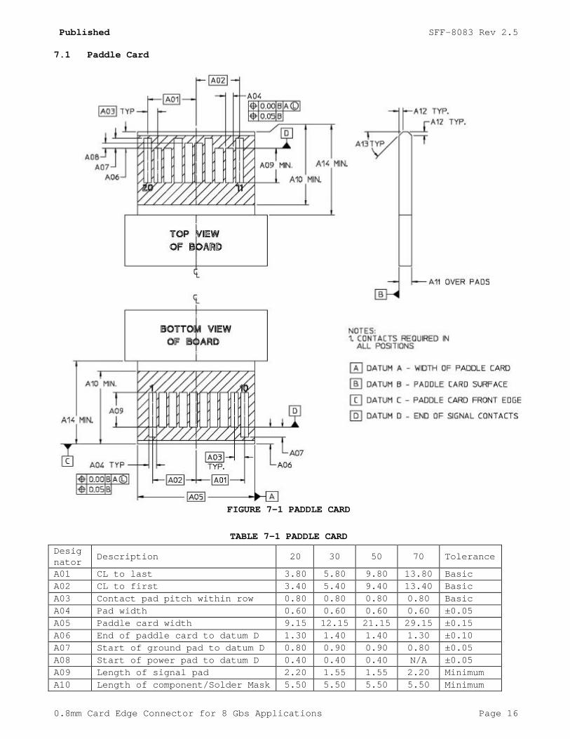
7.1 Paddle Card
FIGURE 7-1 PADDLE CARD
TABLE 7-1 PADDLE CARD
Desig nator
Description 20 30 50 70 Tolerance
A01 CL to last 3.80 5.80 9.80 13.80 Basic A02 CL to first 3.40 5.40 9.40 13.40 Basic A03 Contact pad pitch within row 0.80 0.80 0.80 0.80 Basic A04 Pad width 0.60 0.60 0.60 0.60 ±0.05 A05 Paddle card width 9.15 12.15 21.15 29.15 ±0.15 A06 End of paddle card to datum D 1.30 1.40 1.40 1.30 ±0.10 A07 Start of ground pad to datum D 0.80 0.90 0.90 0.80 ±0.05 A08 Start of power pad to datum D 0.40 0.40 0.40 N/A ±0.05 A09 Length of signal pad 2.20 1.55 1.55 2.20 Minimum A10 Length of component/Solder Mask
keep-out area 5.50 5.50 5.50 5.50 Minimum

Published SFF-8083 Rev 2.5
0.8mm Card Edge Connector for 8 Gbs Applications Page 17
keep-out area A11 Paddle card thickness 1.00 1.00 1.00 1.00 ±0.10
A12 Paddle card end chamfer 0.30 0.30 0.30 0.30 +0.10/ -0.20
A13 Paddle card end chamfer angle 45° 45° 45° 45° Reference
A14 Length from front edge to shoulder
6.00 6.00 6.00 6.00 Minimum

Published SFF-8083 Rev 2.5
0.8mm Card Edge Connector for 8 Gbs Applications Page 18
7.2 Board Side Connector
FIGURE 7-2 BOARD SIDE CONNECTOR

Published SFF-8083 Rev 2.5
0.8mm Card Edge Connector for 8 Gbs Applications Page 19
TABLE 7-2 BOARD SIDE CONNECTOR
Desig nator
Description 20 30 50 70 Tolerance
A01 CL to last 3.80 5.80 9.80 13.80 Basic A02 CL to first 3.40 5.40 9.40 13.40 Basic A03 Contact pitch within row 0.80 0.80 0.80 0.80 Basic B01 Overall width 11.20 15.20 23.20 31.20 Maximum B02 Overall depth 9.20 9.20 9.20 9.20 Maximum B03 Paddle card slot width 9.40 13.40 21.40 29.40 ±0.05 B04 Contact tolerance zone 0.33 0.33 0.33 0.33 Maximum B05 Paddle card slot height 1.35 1.35 1.35 1.35 Maximum B06 Paddle card slot to datum F 2.75 2.75 2.75 2.75 ±0.15 B07 Contact pitch row to row 0.40 0.40 0.40 0.40 Basic B08 Peg to peg 9.60 13.60 21.60 29.60 Basic B09 Peg height 1.40 1.40 1.40 1.40 ±0.05 B10 Peg width 0.90 0.90 0.90 0.90 Reference B11 Peg diameter 1.40 1.40 1.40 1.40 ±0.05 B12 Housing to solder foot 0.41 0.41 0.41 0.41 Reference B13 Overall height 5.40 5.90 5.90 5.90 Maximum B14 Peg CL to solder foot 4.65 4.65 4.65 4.65 Reference B15 Peg CL to card slot 2.43 2.43 2.43 2.43 Minimum B16 Peg CL to contact CL 0.70 0.70 0.70 0.70 ±0.15 B17 Housing Front to contact CL 2.30 2.30 2.30 2.30 ±0.15
Note: Solder footprint configuration shall conform to the footprint defined in 7.3

Published SFF-8083 Rev 2.5
0.8mm Card Edge Connector for 8 Gbs Applications Page 20
7.3 Board Side Connector Footprint
FIGURE 7-3 BOARD SIDE CONNECTOR FOOTPRINT
TABLE 7-3 BOARD SIDE CONNECTOR FOOTPRINT
Desig nator
Description 20 30 50 70 Tolerance
A03 Contact pitch within row 0.80 0.80 0.80 0.80 Basic B07 Contact pitch row to row 0.40 0.40 0.40 0.40 Basic B08 Peg to peg 9.60 13.60 21.60 29.60 Basic C01 Locator peg hole diameter 1.55 1.55 1.55 1.55 ±0.05 C02 Pad width 0.50 0.50 0.50 0.50 ±0.03 C03 Pad length 2.00 2.00 2.00 2.00 ±0.05 C04 Peg hole CL to pad CL 4.10 4.10 4.10 4.10 Basic C05 Locator peg hole CL to pad CL 1.40 1.40 1.40 1.40 Reference C06 Locator peg hole CL to pad CL 1.00 1.00 1.00 1.00 Reference C07 Pad CL to pad CL within row 7.20 11.20 19.20 27.20 Basic C08 Datum H to locator peg hole CL See Note 2 Basic C09 Datum J to locator Peg Hole CL See Note 2 Basic C10 Row CL to row CL 8.20 8.20 8.20 8.20 Basic