sfr core design performance & safety - vasile · pdf fileoutline gen iv specifications...
TRANSCRIPT

SFR CORE DESIGN PERFORMANCE
AND SAFETY
19 SEPTEMBER 201213 SEPTEMBRE 2012 | PAGE 1CEA | 10 AVRIL 2012
A. VASILE
European Nuclear Education Network Association – Gen IV - INSTN | Alfredo Vasile
OUTLINE
GEN IV specifications
Overview of the Design Methodology
SFR core design: example of results, key issues
Application to ASTRID
Conclusions
13 SEPTEMBRE 2012 | PAGE 2CEA | 19 SEPTEMBER 2012

GEN IV CRITERIA
13 SEPTEMBRE 2012 | PAGE 3CEA | 19 SEPTEMBER 2012

GOALS FOR GEN IV FUEL CYCLES
13 SEPTEMBRE 2012 | PAGE 4CEA | 19 SEPTEMBER 2012
Optimization of the use of natural resources
Waste minimization
Proliferation resistance
Recycling options:All paths should be kept available, they could be used in a sequence.
R T
DepU
FP
U Pu MA
R T
DepU
MA
U Pu
FPR T
DepU
FP MA
U Pu
Homogeneous MAsrecycling (GenIV)
Heterogeneous
MAs recyclingU & Pu
recycling

SFR CORE LAYOUT
13 SEPTEMBRE 2012 | PAGE 5CEA | 19 SEPTEMBER 2012
SFR CORE SUBASSEMBLIES
13 SEPTEMBRE 2012 | PAGE 6CEA | 19 SEPTEMBER 2012
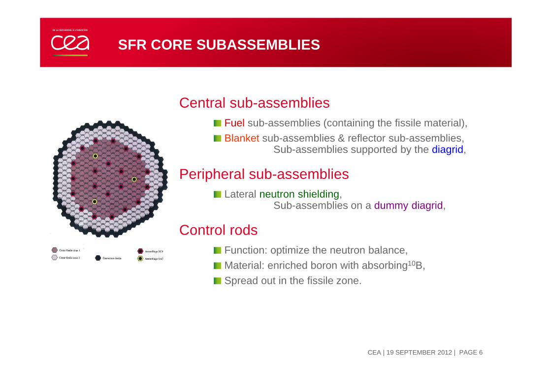
Central sub-assembliesFuel sub-assemblies (containing the fissile material),
Blanket sub-assemblies & reflector sub-assemblies, Sub-assemblies supported by the diagrid,
Peripheral sub-assemblies Lateral neutron shielding,
Sub-assemblies on a dummy diagrid,
Control rodsFunction: optimize the neutron balance,
Material: enriched boron with absorbing10B,
Spread out in the fissile zone.

SFR CORE DESIGN REQUIREMENTS
13 SEPTEMBRE 2012 | PAGE 7CEA | 19 SEPTEMBER 2012
Main core functions:Producing & controlling the power level,Ensuring the fissile material filling density, Guaranteeing & controlling the temperature level, Stabilising and maintaining overall core consistency.
Design issues related to these functions: Neutronics
Power density, safety parameters
Thermal-hydraulicsCooling and monitoring,
Thermomechanics (& materials)Stability and consistency,
Fuel physicochemistryTemperature stability,
InstrumentationMonitoring.
SFR CORE DESIGN PROCESS
13 SEPTEMBRE 2012 | PAGE 8CEA | 19 SEPTEMBER 2012
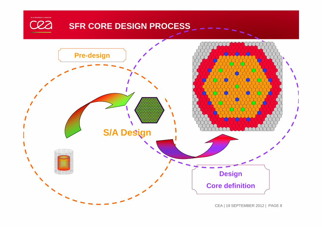
Pre-design
Design
Core definition
S/A Design

SFR CORE DESIGN PROCESS
13 SEPTEMBRE 2012 | PAGE 9CEA | 19 SEPTEMBER 2012
Neutronics
Pre-design
Neutronics Neutronics
Thermo Hydraulic
Mechanic
Fuel Behavior
Materials
Simplified modeling
Preliminary physical studies
Pre design studies Design studies
Feasibility domain
Severe accidents
Detailed modeling
Way of interest
S/A Pre design
Physical behavior
assessmentsCore detailed
image

SFR CORE DESIGN PROCESS
13 SEPTEMBRE 2012 | PAGE 10CEA | 19 SEPTEMBER 2012
1st phase: parametric study
Neutronic assessment
Study of the physical phenomena
Most important parameters to improveSafety (Doppler, Void,…)
Performances (BU,..)
2nd phase: images
Compilation of most promising options from the 1st phase
Core images focusing on:
safety, looking for cores with limited void effect
self sustainability (BG, Pu Inventory)
Economic performances (Cycle length, BU,..)
Neutronic
Elementary physical studies
Neutronic
Pre-design
Pre design studies
SUBASSEMBLY DESIGN PROCESS
13 SEPTEMBRE 2012 | PAGE 11CEA | 19 SEPTEMBER 2012
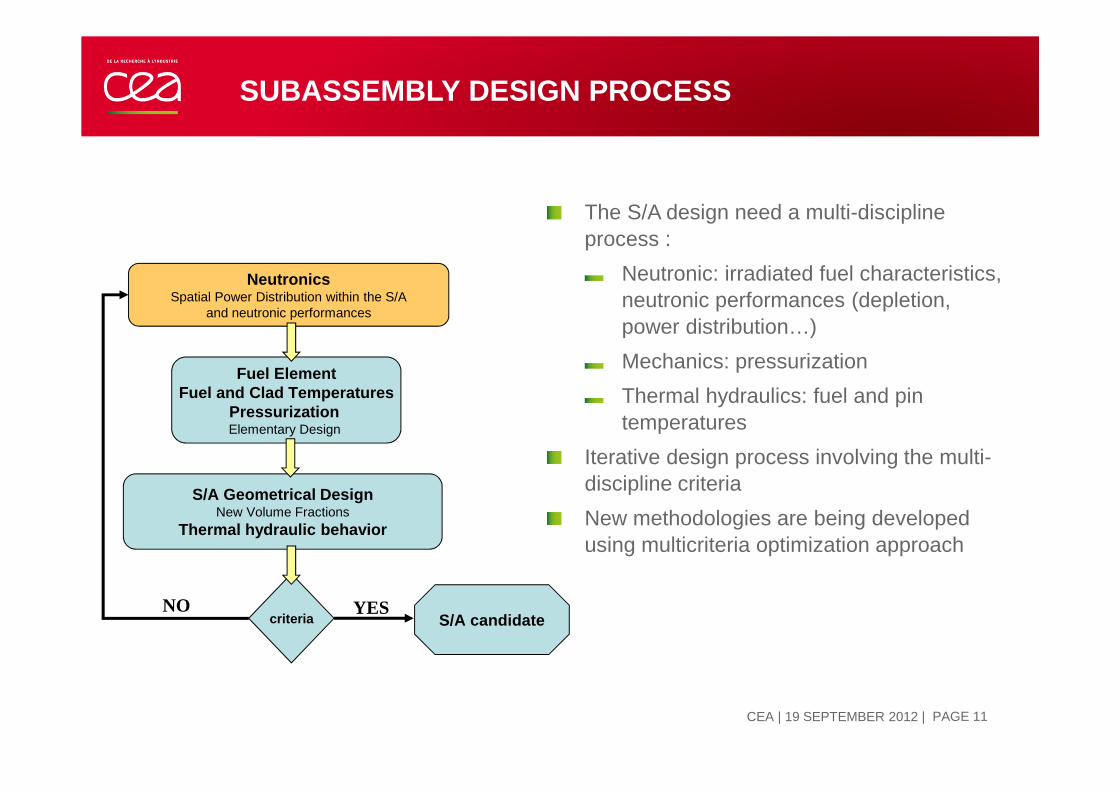
NeutronicsSpatial Power Distribution within the S/A
and neutronic performances
Fuel ElementFuel and Clad Temperatures
Pressurization Elementary Design
S/A Geometrical DesignNew Volume Fractions
Thermal hydraulic behavior
criteria S/A candidateYESNO
The S/A design need a multi-discipline process :
Neutronic: irradiated fuel characteristics, neutronic performances (depletion, power distribution…)
Mechanics: pressurization
Thermal hydraulics: fuel and pin temperatures
Iterative design process involving the multi-discipline criteria
New methodologies are being developed using multicriteria optimization approach

NEUTRONIC PRE DESIGN STUDIES
13 SEPTEMBRE 2012 | PAGE 12CEA | 19 SEPTEMBER 2012
Homogeneous cells calculations without self
shielding
2D RZ core geometry, homogeneous compositions
33 group for flux calculation in diffusion approximation
• Pu content, BG , mass of HN
• Cycle length, BU calculations
• DPA, Max and average power …
• Core safety parameters :
Void effect,
Doppler,
Delayed Neutrons fraction.
Fast implementation and reduced time calculations
Assessment of global parameters
Calculations are performed without uncertainties at this stage

CONCEPTUAL DESIGN
13 SEPTEMBRE 2012 | PAGE 13CEA | 19 SEPTEMBER 2012
Detailed core study (from a pre-design core definition)
Detailed core description
Implementation of control rods and backup systems
Overall optimization
Transfer data to other codes
Neutronics
Thermal hydraulics
mechanicsFuel behavior
Transients & Severe AccidentsSystem
Neutronics Reference Code (MC)

SFR CORE DESIGN STUDIES
13 SEPTEMBRE 2012 | PAGE 14CEA | 19 SEPTEMBER 2012
Heterogeneous cells calculations Pin and S/A description with fine self
shielding treatment
Detailed core description (3D Hex Z)
Loading Batch Management
33 group for flux calculation in transport theory
Global performances
Reaction rates distribution per S/A and meshes
Feedback coefficients per S/A and meshes
Individual control rod worth and detailed monitoring of safety criteria (10$,cold and hot shutdown, handling error, ,..)
Most accurate calculations and time ratio
Specific calculation scheme
Detailed characterization
Uncertainties depends on the qualification domain

DESIGN METHODOLOGY APPLIED TO SFR SYSTEMS
| PAGE 15
ICAPP'12, Chicago, USA | 24,28 june 2012

EXEMPLE OF PARAMETRIC STUDIES
13 SEPTEMBRE 2012 | PAGE 16CEA | 19 SEPTEMBER 2012
Ways to improve the breeding gain Ways to improve the Void/Doppler ratio Geometry modifications
Increase of the fuel volume fraction Decrease of the sodium volume fraction Increase of the height / diameter ratio (0<H/D<1) Decrease of the core volume
Increase of the core volume Decrease of the height / diameter ratio (0<H/D<1)
Increase of the sodium volume fraction Increase of the fuel volume fraction
Increase of the core radius Modification of the core radius
« options » addition Minor actinides addition Sodium plenum addition Sodium plenum addition Addition of CaH2 moderator Annular core Addition of B4C moderator Addition of B4C moderator Addition of an internal fertile axial blanket Addition of an internal fertile axial blanket Annular core
Addition of CaH2 moderator Minor actinides addition
Fuel type Nitride Carbide Carbide Oxide Metallic Nitride
Oxide Metallic
Large improvement Large deterioration
No Effect
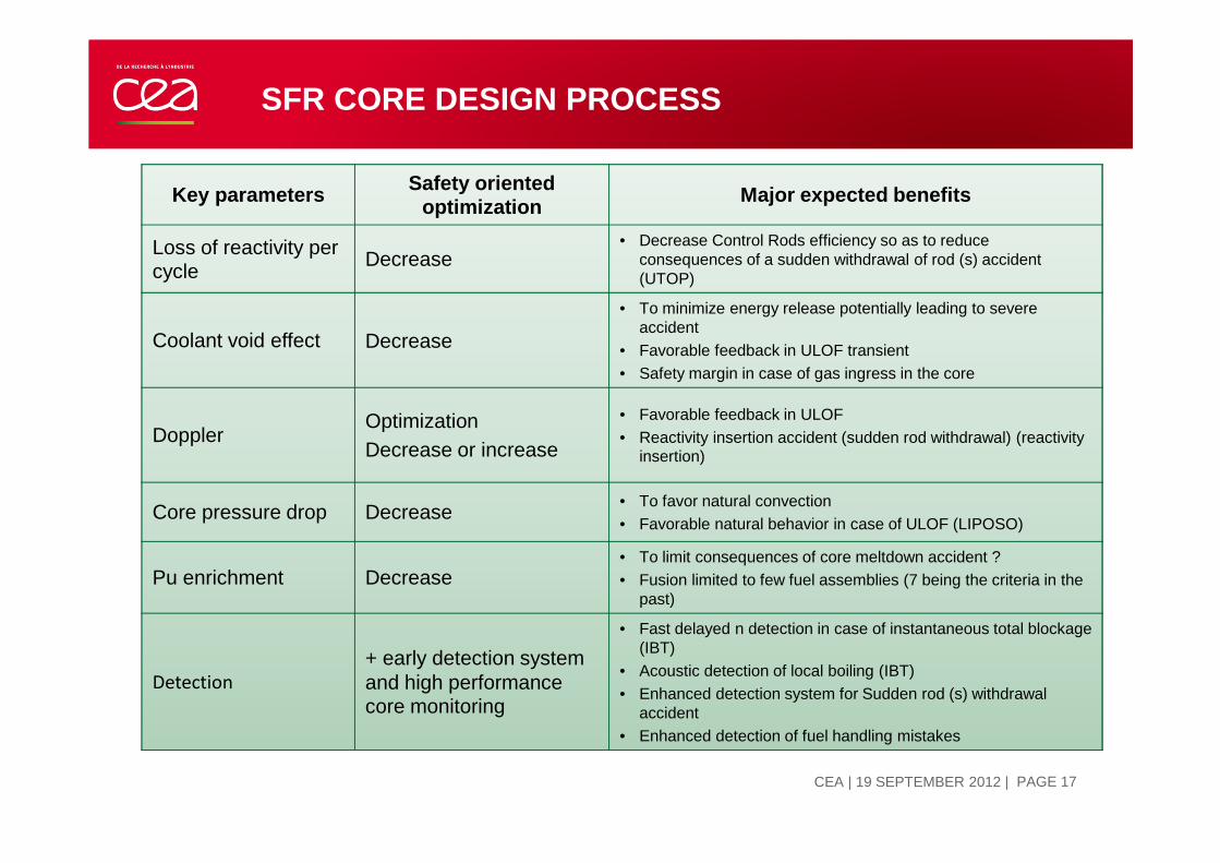
SFR CORE DESIGN PROCESS
13 SEPTEMBRE 2012 | PAGE 17CEA | 19 SEPTEMBER 2012
Key parameters Safety oriented optimization
Major expected benefits
Loss of reactivity per cycle
Decrease• Decrease Control Rods efficiency so as to reduce
consequences of a sudden withdrawal of rod (s) accident (UTOP)
Coolant void effect Decrease
• To minimize energy release potentially leading to severe accident
• Favorable feedback in ULOF transient• Safety margin in case of gas ingress in the core
DopplerOptimizationDecrease or increase
• Favorable feedback in ULOF• Reactivity insertion accident (sudden rod withdrawal) (reactivity
insertion)
Core pressure drop Decrease• To favor natural convection• Favorable natural behavior in case of ULOF (LIPOSO)
Pu enrichment Decrease• To limit consequences of core meltdown accident ?• Fusion limited to few fuel assemblies (7 being the criteria in the
past)
Detection
+ early detection system and high performance core monitoring
• Fast delayed n detection in case of instantaneous total blockage (IBT)
• Acoustic detection of local boiling (IBT)• Enhanced detection system for Sudden rod (s) withdrawal
accident• Enhanced detection of fuel handling mistakes

SFR / PWR
13 SEPTEMBRE 2012 | PAGE 18CEA | 19 SEPTEMBER 2012
Reactor PWR SFR
Thermal power (MW) 4250 3600
Electrical power (MW) 1450 1450
Fuel UOX (~4%), MOX (~8%) MOX (~20%)
Coolant water sodium
Primary pressure (b) 155 1
Cladding diameter (mm) 9.4 8.2
Bundle geometry square hexagonal
Pins per S/A 264 331
Fissile hight (cm) 420 100
Number of S/A in the core 241 387
Core volume (m3) 46 12
Uranium, Plutonium mass (t) 130 42
Core inlet temperature (°C) 300 400
Core ∆T (°C) 40 150
Power density (W/cm3) 90 300
Reactivity control Control rods (~80), Soluble Boron Control rods (~30)
SFR S/A
PWR S/A

SFR SUBASSEMBLY
13 SEPTEMBRE 2012 | PAGE 19CEA | 19 SEPTEMBER 2012
Wrapper tube
Fuel bundle Sodium inlet
Axial blanket bundle

PHENIX, SUPER PHENIX AND EFR
13 SEPTEMBRE 2012 | PAGE 20CEA | 19 SEPTEMBER 2012
Reactor PHENIX SUPER PHENIX EFR
Thermal power (MW) 563 2990 3600
Pellet diameter (mm) 5.507.14
(central hole 2 mm)6.94
(central hole 2 mm)
Cladding diameter (mm) 5.65 8.5 8.20
Pins per S/A 217 271 331
Fissile hight (cm) 85 100 100
Blanket zone hight (radial/upper/lower) (cm) 52/22/30 60/30/30 40/15/25
S/A width across flats (cm) 12.37 17.3 18.3
S/A pitch (cm) 12.72 17.9 18.8
Equivalent core fissile radius (cm) 68 179 194
Core fissile volume (m3) 1.2 10 12
Number of fuel S/AsZone Enrichment 1 Zone Enrichment 2 Zone Enrichment 3
1045054-
364193191
-
38720710872
Number of control rods 6 21 24
Number of safety control rods 1 6 9
Number of blanket S/As78
(2 rings)237
(3 rings)78
(1 rings)

13 SEPTEMBRE 2012 | PAGE 21CEA | 19 SEPTEMBER 2012
REACTIVITY EFFECTS - INTRINSIC
.comb
.combDOPDOP T
dTKd α=ρ

13 SEPTEMBRE 2012 | PAGE 22CEA | 19 SEPTEMBER 2012
REACTIVITY EFFECTS - LOCAL
2) LOCAL EXPANSION
Sodium densityCladding and wrapper tube radialCladding and wrapper tube axialFuel axial (free or linked to the cladding)
Remarks:
No radial fuel expansion effect because fuel radial expansion is limitedby the cladding
When the fuel is linked to the cladding the axial expansion is driven by the cladding axial expansion.
iii dT.kd =ρ

13 SEPTEMBRE 2012 | PAGE 23CEA | 19 SEPTEMBER 2012
REACTIVITY EFFECTS - GLOBAL

13 SEPTEMBRE 2012 | PAGE 24CEA | 19 SEPTEMBER 2012
Type of effect Effect Related to FormulationValue (SPX)
pcm / °C
Intrinsec Doppler T fuel (��) �ρ ���
��
. ��� -0.08
Local
Sodium density T sodium ��) �ρ � �. �� +0.33
Cladding radial T cladding ���) �ρ � �� . ��� +0.08
Cladding axial T cladding ���) �ρ � ���. ��� +0.07
Wrapper tube radial T wrapper tube (��� �ρ � �� . ��� +0.01
Wrapper tube axial T wrapper tube (��� �ρ � ���. ��� +0.04
Fuel axial (linked fuel) T cladding ���) �ρ � �����. ��� -0.31
Fuel axial (free fuel) T fuel (��) �ρ � �����. ��� -0.22
Global
Diagrid radial T diagrid (����)�ρ
� ����. �����-1.01
Relative expansion core/vessel/control rods
T core, T control rods,T vessel
�ρ � ����. �� �� � 12mm/°C
REACTIVITY EFFECTS
13 SEPTEMBRE 2012 | PAGE 25CEA | 19 SEPTEMBER 2012
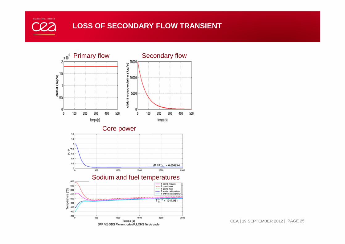
LOSS OF SECONDARY FLOW TRANSIENT
Primary flow Secondary flow
Core power
Sodium and fuel temperatures

13 SEPTEMBRE 2012 | PAGE 26CEA | 19 SEPTEMBER 2012
LOSS OF SECONDARY FLOW TRANSIENT
Core inlet temp. ����, ρDiagrid < 0, P ����, ρDOPPLER > 0,ρSodium > 0,ρFuel < 0,ρCore/Vessel/Control rods> 0
Core power could be stabilised but isothermal sodium temperature >1000°C)
Reactivity
Doppler
Sodium
Diagrid
Core/Vessel/CR
13 SEPTEMBRE 2012 | PAGE 27CEA | 19 SEPTEMBER 2012
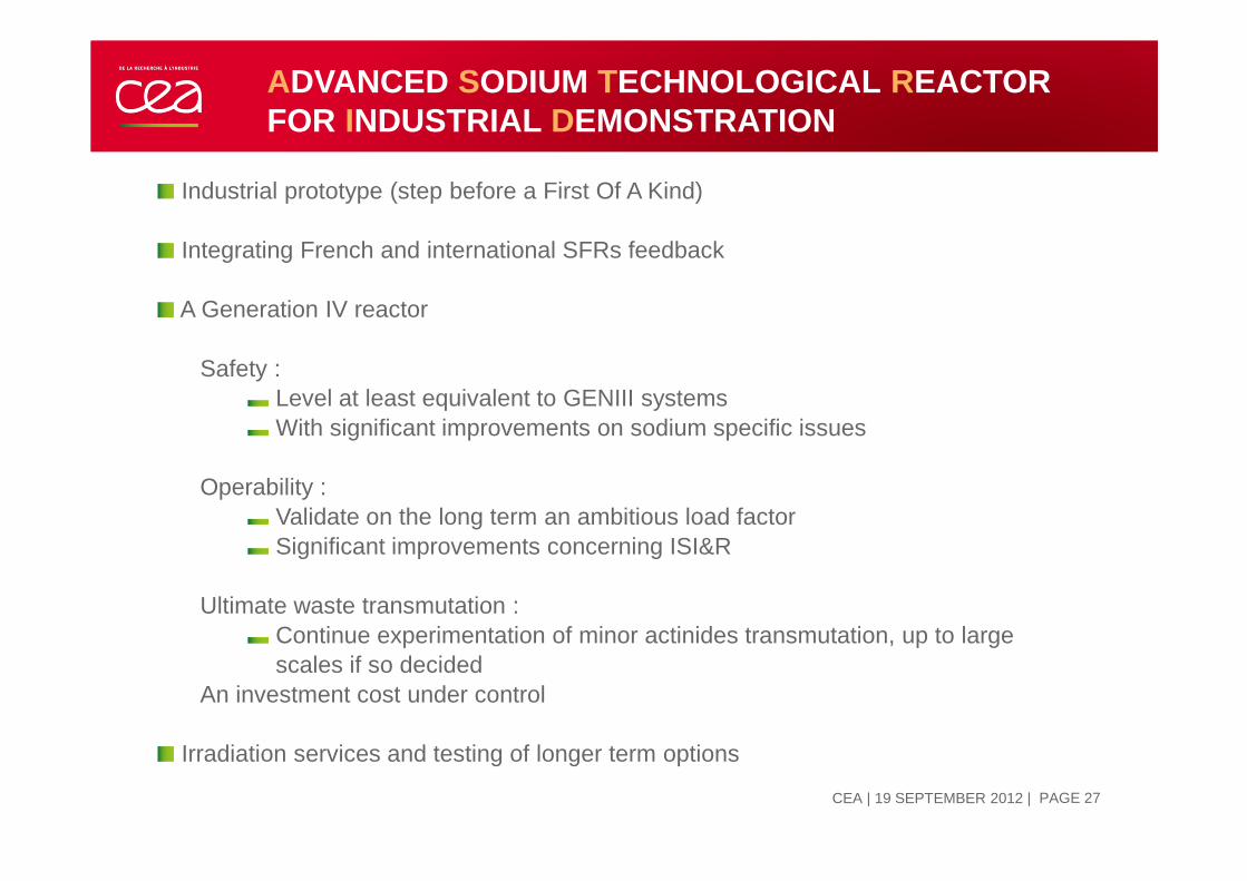
ADVANCED SODIUM TECHNOLOGICAL REACTOR FOR INDUSTRIAL DEMONSTRATION
Industrial prototype (step before a First Of A Kind)
Integrating French and international SFRs feedback
A Generation IV reactor
Safety :Level at least equivalent to GENIII systemsWith significant improvements on sodium specific issues
Operability :Validate on the long term an ambitious load factorSignificant improvements concerning ISI&R
Ultimate waste transmutation :Continue experimentation of minor actinides transmutation, up to large scales if so decided
An investment cost under control
Irradiation services and testing of longer term options

13 SEPTEMBRE 2012 | PAGE 28CEA | 19 SEPTEMBER 2012
MAIN FEATURES
S/A : UPuO2 fuel (annular pellets)Fuel pins with spacerHexagonal wrapper tube
General performances objectives for the coreAverage burn-up > 100 GWd/tBreak-even core : breeding gain ≈ 0 (without fertile radial blanketFuel cycle length : 400- 490 efpdTransmutation capabilities for MA transmutationSafety improvement
PP
DHX
IHX PP
REDAN
CORE
Pool type reactor : 1500 MWthSodium cooled3 Primary pumps, 4 IHX

13 SEPTEMBRE 2012 | PAGE 29CEA | 19 SEPTEMBER 2012
SAFETY PERFORMANCE TARGET
Favorable natural behavior during loss of Flow transients
Target criteria : no sodium boiling for a ULOSSP transient(Unprotected Loss Of Station Supply Power)
Sodium void effect minimizedTarget criteria : Na void effect < 0
Natural behavior favorable for a complete control rod withdrawal (without detection) Target criteria : no fuel fusion
Improvement of behavior in case of sub-assembly Total Instantaneous BlockageEnsure sub -criticality of 7 melted adjacent sub-assemblies
Elimination of Transient of PowerCompaction or gas flow are " practically eliminated" by design.

CFV CONCEPT
| PAGE 30
ICAPP'12, Chicago, USA | 24,28 june 2012

13 SEPTEMBRE 2012 | PAGE 31CEA | 19 SEPTEMBER 2012
CFV CORE LAYOUT

13 SEPTEMBRE 2012 | PAGE 32CEA | 19 SEPTEMBER 2012
CFV CORE LAYOUT
Fissile zone
Blanket zone
Plenum zone
Absorber zone
Theses Features give a
negative Sodium void worth

13 SEPTEMBRE 2012 | PAGE 33CEA | 19 SEPTEMBER 2012
CORE DESIGN OPTIONS: SFRV2 AND CFV LAYOUTS
SFRv2 – AIM1 – 1500 MWth CFV – V1 - AIM1 – 1500 MWth
Neutronic and thermal-hydraulic core calculations were performed with CEA’s reference system codes ERANOS and CATHARE.

CORE PERFORMANCES
| PAGE 34
ICAPP'12, Chicago, USA | 24,28 june 2012

13 SEPTEMBRE 2012 | PAGE 35CEA | 19 SEPTEMBER 2012
CFV AND V2B PERFORMANCES 1/2
Core design CFV V2B 1500
Thermal Power 1500 MW
Elect. Power 600 MW
Fuel Residence Time 1440 EFPD 1560 EFPD
Fuel Cycle Length 360 EFPD 390 EFPD
∆ρ∆ρ∆ρ∆ρ (cycle) - 1550 pcm - 875 pcm
∆ρ∆ρ∆ρ∆ρ (efpd) - 4,3 pcm - 2,2 pcm
Batch 4
Fissile zone diameter 340 cm 312 cm
S/A Pitch 17,5 cm 16,8 cm
Nb fuel elements C1/C2 177 / 114 144 / 144
Pin diameter 9,7 mm 10,73 mm
Pins/Assembly 217 169
CSD/DSD Nb 12 / 6 18 / 6
High Cycle length, positive
to competitiveness
Weak reactivity loss, favorable to limit CR withdrawal

13 SEPTEMBRE 2012 | PAGE 36CEA | 19 SEPTEMBER 2012
CFV AND V2B PERFORMANCES 2/2
Core design CFV V2B 1500
Pvol (Fiss.+ int. fertile) 226 W/cm3 194 W/cm3
Pvol (Fissile)) 258 W/cm3 194 W/cm3
Fuel burnup C1/C2 105/ 69 GWd/t 76 / 67 GWd/t
Pu enrichment C1/C2 23,5 / 20 % 13,9 / 17,6 %
DPA max 113 108
Void effect EOC -0,5 $ +5,1 $
ββββeff 364 pcm 373 pcm
Breeding Gain -0,02 -0,05
Pu inventory (HN) 4,9 t 5,3 t
Max linear power rate 483 W/cm 407 W/cm
Core pressure drop 2,6 b >3b
Total core flow rate 7990 ks/s
Inlet core temperature 400°C
Outlet core temperature 550°C
Criteria reached for CFV, good for safetyand public acceptance
Break Even Core, durability
Favorable for natural convection

13 SEPTEMBRE 2012 | PAGE 37CEA | 19 SEPTEMBER 2012
CFV AND V2B FEEDBACK COEFFICIENTS
CFV SFRV2 V0
Axial clad expansion 0,061 0,064 pcm /°C
Radial clad expansion 0,089 0,147 pcm /°C
Sodium expansion 0,09 0,492 pcm /°C
Fuel expansion -0,23 -0,254 pcm /°C
Doppler Constant Fissile zone (KD) -664 -526 pcm
Doppler constant Fertile slab (KD) -355 - pcm
Plate expansion -0,88 -0,797 pcm /°C
Favorable Sodium worth
feedback coefficient for TH
transient
Favorable Doppler
constant, upgrade TOP
behavior

TRANSIENT BEHAVIOR
Thermal hydraulic transients
Control rod withdrawal
| PAGE 38
ICAPP'12, Chicago, USA | 24,28 june 2012

13 SEPTEMBRE 2012 | PAGE 39CEA | 19 SEPTEMBER 2012
THERMAL HYDRAULIC TRANSIENTS
To investigate the core capabilities, 3 mains unprotected transients were assessed, in comparison to classical SFR core design.
ULOSSP (Unprotected Loss Of Station Supply Power) : blackout transient without scram and without starting up of ultimate emergency systems or decay heat removal
ULOF (Unprotected Loss of Flow): loss of primary pumps without scram, secondary pumps remaining at nominal flow.
ULOHS (Unprotected Lost Of Heat Sink): Secondary pumps tripped in 100s without scram, the primary pumps still remaining in normal operation
Hypothesis for comparison:Halving time for the Primary Pumps is 20sNo optimization of flow rate between S/A
All results presented are given for the hot S/A

13 SEPTEMBRE 2012 | PAGE 40CEA | 19 SEPTEMBER 2012
CFV ULOSSP
Power
Na density
Inlet Temp
Outlet Temp
Boiling Temp
Doppler
13 SEPTEMBRE 2012 | PAGE 41CEA | 19 SEPTEMBER 2012
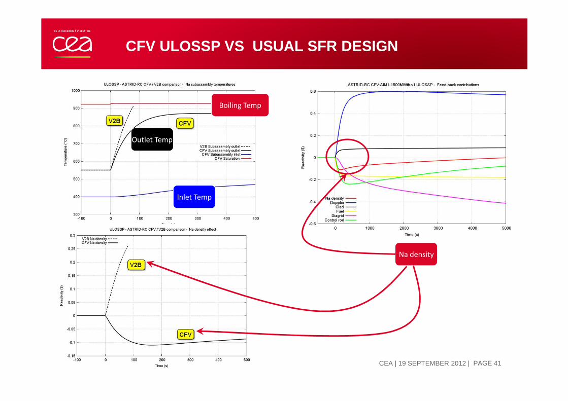
CFV ULOSSP VS USUAL SFR DESIGN
Inlet Temp
Outlet Temp
Boiling Temp
Na density

13 SEPTEMBRE 2012 | PAGE 42CEA | 19 SEPTEMBER 2012
CFV VS CLASSICAL SFR DESIGN (ULOHS)
13 SEPTEMBRE 2012 | PAGE 43CEA | 19 SEPTEMBER 2012
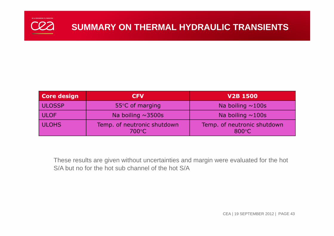
SUMMARY ON THERMAL HYDRAULIC TRANSIENTS
Core design CFV V2B 1500
ULOSSP 55°C of marging Na boiling ~100s
ULOF Na boiling ~3500s Na boiling ~100s
ULOHS Temp. of neutronic shutdown700°C
Temp. of neutronic shutdown800°C
These results are given without uncertainties and margin were evaluated for the hot S/A but no for the hot sub channel of the hot S/A

13 SEPTEMBRE 2012 | PAGE 44CEA | 19 SEPTEMBER 2012
CONTROL ROD WITHDRAWAL
All the CRW that can occur on the CFV core can be detected by two devoted independent systems of core detection which stop the reactor by scram.The first system prompted is the core temperature monitoring; the second is the neutron detectionIn case of a total control rod withdrawal (corresponding to the failure of two strong lines of defense) the outer rods do not comply with the criterion of no melting
( ) [ ][ ])(.1.)(.'1 0 tbtkPtP ilinlin oρρ ∆+∆+=
Plin0, initial linear power of the considered fuel sub-assembly, k’i , relative variation of linear power density per unit of inserted reactivity,∆ρ total reactivity worth of the control rod between its initial position in the core and the parking position at the end of the withdrawal.b0 is the relative variation of the total power of the core per unit of reactivity inserted

13 SEPTEMBRE 2012 | PAGE 45CEA | 19 SEPTEMBER 2012
CONCLUSION
Sodium cooled Fast Reactors core design is an iterative and integrated process.
It must accommodate different requirements mainly related to safety, fissile materials balance and economic aspects.
It includes neutronics, thermal-hydraulics, mecanics, fuel behaviourfor the core itself but also whole plant behavior under normal and accidental conditions.
Pre-conceptual design studies of ASTRID prototype core shows significant improvements related to previous SFRs designs (SPX, EFR).

Nuclear Energy DirectorateReactor Studies Department
Commissariat à l’énergie atomique et aux énergies alternatives
Centre de Cadarache | 13108 Saint Paul Lez Durance
T. +33 (0)442257000
Etablissement public à caractère industriel et commercial | RCS Paris B 775 685 01913 SEPTEMBRE 2012
| PAGE 46
CEA | 10 AVRIL 2012
Thank you for your attention